RANGE
COOKERS
MAJESTIC - PANORAMAGIC - NOSTALGIE - PRO LINE
PROFESSIONAL PLUS 06 - 07 - 09 - 30 - 10 - 12 - 15
EN User manual


3
Appliances’ data
The label with the technical characteristics, in addition to being
printed on the cover, is applied to the door frame of the oven and
is visible when the door is open.
WARNING! These warnings apply to dierent types of
appliances. Be sure to correctly identify the type you own (see
the technical label). These warnings are valid for the countries
listed on the label.
1. Before using the appliance, carefully read the instruction
manual, which contains, among other things, very important
information regarding safety during installation, use, and
maintenance. Keep the instruction manual safe for future
reference and for identifying the serial number.
2. The electrical safety of this appliance is guaranteed only if the
correct grounding connection is made as required by current
regulations. It is essential to ensure that these regulations
have been followed; if in doubt, contact a qualied person
to thoroughly check the electrical system. The manufacturer
assumes no responsibility for damage caused by a faulty
grounding system.
3. Before connecting the appliance, ensure that the technical
characteristics on the label match those of the electrical
system. Installation/adjustment must be carried out by
qualied personnel.
4. Ensure that there is enough air circulation around the
appliance. This appliance is not connected to a combustion
product evacuation system, so special attention must be
paid to the ventilation of the room, in accordance with the
applicable installation standards.
5. Using a gas cooking appliance generates heat and humidity
in the room where it is installed. Ensure proper ventilation
in the kitchen: keep natural ventilation openings open or
install a mechanical ventilation device (such as an extractor
hood). Intense and prolonged use of the appliance may
require additional ventilation, such as opening a window or
increasing the power of the mechanical extractor if available.
6. The power cord does not come with a plug. For connections,
see the “Electrical Connection” section. It is recommended
not to use adapters, multiple outlets, or extensions.
7. For direct connection to the network, a device must be
provided that ensures disconnection from the network, with
contact opening distances allowing complete disconnection
under overvoltage category III conditions, in compliance with
installation rules.
8. The appliance should not be installed on a pedestal.
9. When the appliance is unused for an extended period,
disconnect the power supply, turn o the main switch, and
close the gas supply.
10. Do not obstruct the air vents or heat dissipation openings.
11. If the power cord is damaged, it must be replaced by the
manufacturer, its authorized service center, or by a qualied
person with similar qualications, in order to prevent any
risks.
IMPORTANT SAFETY WARNINGS
12. The damaged power cable of the appliance must only
be replaced by an authorized service provider from the
manufacturer.
13. The appliance should only be used for its intended purpose
(cooking). Any other use (e.g., heating a room) is improper
and thus dangerous. The manufacturer disclaims any
responsibility for damages caused by such improper uses.
14. The appliance is not intended to be operated via an external
timer or a separate remote control system.
15. Using any electrical appliance requires adherence to some
basic rules:
- Never touch the appliance with wet or damp hands or feet.
- Never use the appliance barefoot.
- Avoid using extension cords and, if necessary, take all
possible precautions.
- Never pull the power cord to unplug it.
- Do not expose the appliance to weather conditions (rain,
sun, etc.).
- Attention: Accessible parts may become very hot during
use. Keep children under 8 years old away from the
appliance unless constantly supervised. This appliance
can be used by children aged 8 and older and by people
with reduced physical, sensory, or mental capabilities or
lack of experience and knowledge, provided they are under
adequate supervision or have been instructed on the
safe use of the appliance and understand the associated
dangers. Children must not play with the appliance.
Cleaning and maintenance must not be carried out by
children without supervision.
16. Warning: Some accessible parts of the facade, grill, and
griddle may become very hot during use: keep children away.
17. During use, the appliance heats up considerably. Never touch
the internal elements of the oven.
18. Before cleaning the appliance or performing maintenance,
disconnect the appliance by unplugging it or turning o the
electricity via the appropriate switch.
19. In case of malfunction or poor performance, turn o the
appliance, close the gas valve, and do not attempt any repairs.
Repairs must be carried out exclusively by an authorized
service center. Always insist on using original replacement
parts. Failure to follow these instructions may compromise
the appliance’s safety.
20. Do not place unstable or deformed pots on the burners or
electric plates as they may accidentally tip over.
21. Ensure that when the appliance is not in use, the knobs are
exactly in the “
”/“ ” position.
22. Do not leave the cooking plate on without pots, as it will quickly
reach the maximum temperature, potentially damaging the
appliance or surrounding furniture.
23. Some parts of the appliance, particularly electric plates,
remain hot for a long time aer use. Be careful not to touch
them.
24. Do not use ammable liquids (alcohol, gasoline, etc.) near the
appliance when it is in operation.

4
IMPORTANT SAFETY WARNINGS
25. If small appliances are used near the cooking surface, be
careful to avoid the electrical cord touching the hot parts of
the appliance.
26. Gas appliances must be installed in well-ventilated rooms.
Therefore, ensure that the installation complies with the
instructions in the “Installation” section.
27. The materials used to construct this appliance
are environmentally friendly and recyclable.
Packaging waste should not be le within
reach of children but should be disposed of
using appropriate recycling channels. For the
disposal of your appliance, use the disposal
options provided by your retailer and/or local
municipality; remember to make the appliance
unusable before disposal.
28. In case the rotation of the gas taps is sti or faulty, do not
attempt any operation on the tap. Close the gas supply and
contact the authorized service center.
29. Do not use steam cleaners for the internal cleaning of the
oven.
30. Do not use abrasive cleaners or sharp metal tools to clean the
oven door glass, as they may damage the surface and cause
it to break.
31. Do not modify or alter the appliance.
32. To prevent overheating, do not install the appliance behind
decorative doors.
33. Use only the recommended meat thermometer for this oven.
34. Warning: Leaving the appliance unattended with objects,
fats, and oils can be dangerous and may cause a re.
35. The appliance must be used by responsible personnel.
36. Warning: The use of inappropriate or non-compliant
protections may cause res and/or damage.
37. Warning: Automatic cooking with fats or oils may be
dangerous and can cause res.
38. Warning: Fire hazard: Do not store objects on the cooking
surfaces.
39. Warning: In case of re, never attempt to extinguish a ame/
re with water. Instead, turn o the appliance and cover the
ame with a lid or a reproof blanket.
40. Warning: Metal objects such as knives, forks, spoons, or lids
should not be placed on top of the appliance as they may
heat up.
41. Warning: Do not use the gas burners if the ame is unstable.
42. Ensure that the ame spreader crowns are correctly
positioned in their seats with their respective caps.
43. Do not leave the appliance unattended during cooking
processes that may release fats or oils.
44. Do not touch the heating elements of the appliance when in
operation. Allow them to cool before attempting any cleaning.
45. Cooking food in plastic or aluminum containers on hot
cooking zones is prohibited, as is placing plastic or aluminum
foil objects on the cooking surface.
46. Do not apply aluminum foil sheets to cover the burners or
cooking surface.
47. Do not use the appliance surface as a worktop; sharp objects
may scratch it.
48. Cookware or grills must be placed within the perimeter of the
cooking zone.
49. Warning: Do not use frying pans, pots, grills, or grilling
stones that exceed the maximum size indicated for each
individual burner; they should not cover multiple burners
simultaneously. Heat accumulation could damage the
appliance.
50. In the case of spillage or overow, remove the excess liquid
from the cooking surface.
51. Do not place empty pots on the cooking zones.
52. The cooking zones must not operate without cookware.
53. The oven door hinges can be damaged if too much weight
is placed on them. Do not put heavy items on the open oven
door, and avoid leaning on it while cleaning the inside of the
oven. Never stand on the open oven door, and do not let
children sit on it.
54. Do not place racks, baking trays, or any other accessories
directly on the bottom of the oven. Improper use may
compromise heat distribution, adversely aect cooking
performance, and damage the appliance. Use accessories
only in their designated positions and in accordance with
the manufacturer’s instructions.
ATTENTION: Do not use the pyrolysis function before remo-
ving excess stimated residues during previous cooking.
DO NOT USE OR STORE FLAMMABLE MATERIALS IN THE
APPLIANCE STORAGE DRAWER OR NEAR THIS APPLIAN-
CE.
DO NOT SPRAY AEROSOLS IN THE VICINITY OF THIS
APPLIANCE WHILE IT IS IN OPERATION.
DO NOT USE THIS APPLIANCE AS A SPACE HEATER.
DO NOT PLACE ARTICLES ON OR AGAINST THIS AP-
PLIANCE.
DO NOT MODIFY THIS APPLIANCE.
THESE APPLIANCES ARE NOT SUITABLE FOR
AFTERMARKET LIDS OR COVERS.
First use of the oven
- Warning: The surfaces of the heated drawer may become
hot during operation. When using the oven for the rst
time, operate it empty for approximately 1 hour at 230°C,
preferably keeping the kitchen windows open.

5
IMPORTANT SAFETY WARNINGS
- When using the oven for the rst time, operate it empty
for approximately 1 hour at 230°C, leaving the kitchen
windows open if possible. The oven may emit unpleasant
odors due to production residues such as fats, oils, or
resins. Once the oven has cooled, clean it following the
instructions in the “Cleaning and Care of the Oven”
section.
- Aer the indicated time has passed, the oven is ready for
the rst cooking use.
- Do not cover the inside of the oven with aluminum foil to
ease cleaning. This will aect the appliance’s performance
and may damage the enamel.
- All accessories that come into direct contact with
food should be thoroughly cleaned before use using
appropriate cleaning products.
- The appliance must be installed by authorized personnel.
The installer is not responsible for any damage caused by
errors in electrical connection.
Models with induction hob
Precautions before use
- The appliance must only be used for cooking food and not
for any other domestic or industrial purposes.
- Remove any stickers from the glass of the hob.
- Do not modify or alter the appliance.
- Do not use the hob as a work surface.
- The appliance must be connected and installed in
accordance with local regulations.
- Do not use extension cords for the connection.
- The appliance cannot be used with cookware that is not
suitable for induction cooking.
- This appliance can be used by children aged 8 and above,
and by persons with reduced physical, sensory, or mental
capabilities, or by those without experience or knowledge,
provided they are under adequate supervision or have
been instructed in the safe use of the appliance and are
aware of the associated dangers.
- Warning: This appliance and its accessible parts become
very hot during use. Keep children under 8 years old away
unless they are continuously supervised.
Use of the appliance
- Aer use, turn o the cooking zone using its control device
and do not rely on the pan detection system.
- Warning: Leaving the appliance unattended with objects,
fats, and oils can be dangerous and may cause a re.
- Warning: In case of re, never attempt to extinguish a
ame/re with water. Instead, turn o the appliance and
cover the ame, for example, with a lid or a reproof
blanket.
- Cleaning and maintenance operations should not be
carried out by children without supervision.
- Ensure that the power cable does not come into contact
with the glass or the pot.
- Magnetic objects such as credit cards, oppy disks,
calculators should not be placed near the appliance while
in use.
- Do not use any metallic objects except cookware suitable
for induction.
- Do not cover the cooking zone with ammable materials.
- The appliance must be used by responsible personnel.
- Metal objects such as knives, spoons, forks, or lids should
not be placed on the hob surface as they may heat up.
- If the surface is cracked, turn o the appliance to prevent
the risk of electric shock.
- Warning: The appliance is not designed to operate with an
external timer or remote control system.
- Warning: Do not use steam cleaners to clean the hob.
Precautions to avoid damaging the appliance
- Inappropriate cookware may damage the surface of the
hob.
- Do not use abrasive materials for cleaning.
- Avoid dropping heavy objects on the hob surface.
- Place pots gently on the hob.
- Ensure that the ventilation of the appliance complies with
the instruction manual.
- Do not place empty pots on the hob.
- Sugar, synthetic materials, or aluminum materials should
not come into contact with the cooking zones.
- Avoid placing hot containers on the display.
In case of malfunction
- In the event of a malfunction, turn o and disconnect the
appliance.
- If the glass has cracks or breaks, disconnect the appliance
and contact the authorized service center.
- Any repairs should be performed by authorized personnel.
Precautions
- Ensure that the pot is placed in the center of the cooking
zone. Ideally, the bottom of the pot should cover the entire
cooking zone.
- The magnetic eld generated by the induction hob
may aect the proper functioning of pacemakers. It
is recommended to seek detailed information from a
healthcare professional.
- Avoid contact with the cooking zones of synthetic
materials or aluminum.
To keep the appliance ecient and safe, maintenance should
be entrusted to specialized technicians or authorized service
personnel. Choose cookware with lids based on the amount of
food to be cooked.
6
INSTRUCTIONS FOR USE
Gas hob
Correct use of burners
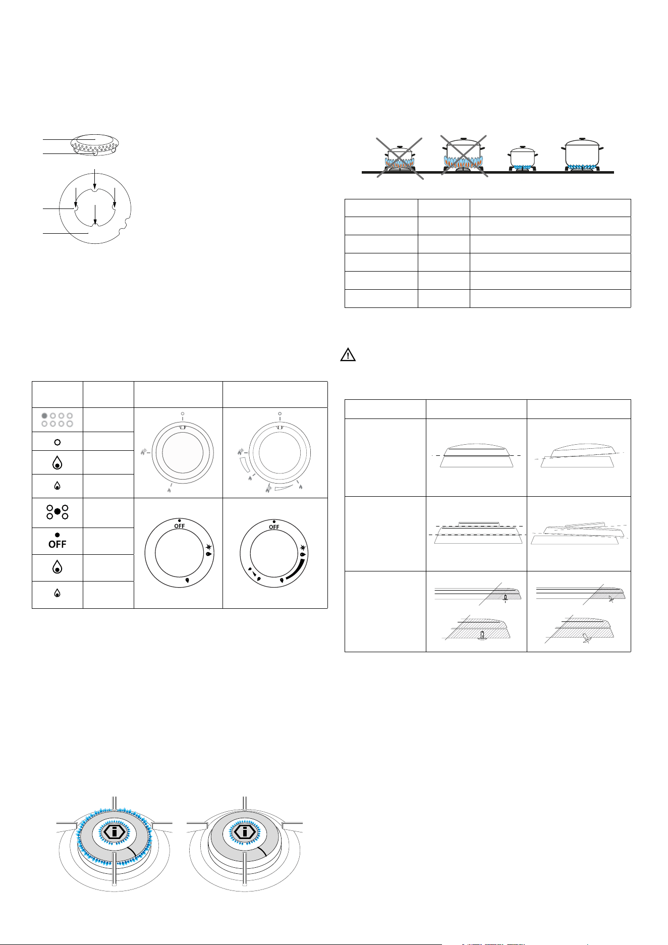
Correctly position the
flame spreader “B”. To
do so, align the 4 teeth
“C” of the flame spreader
with the recess “D” of the
aluminum cup “A”
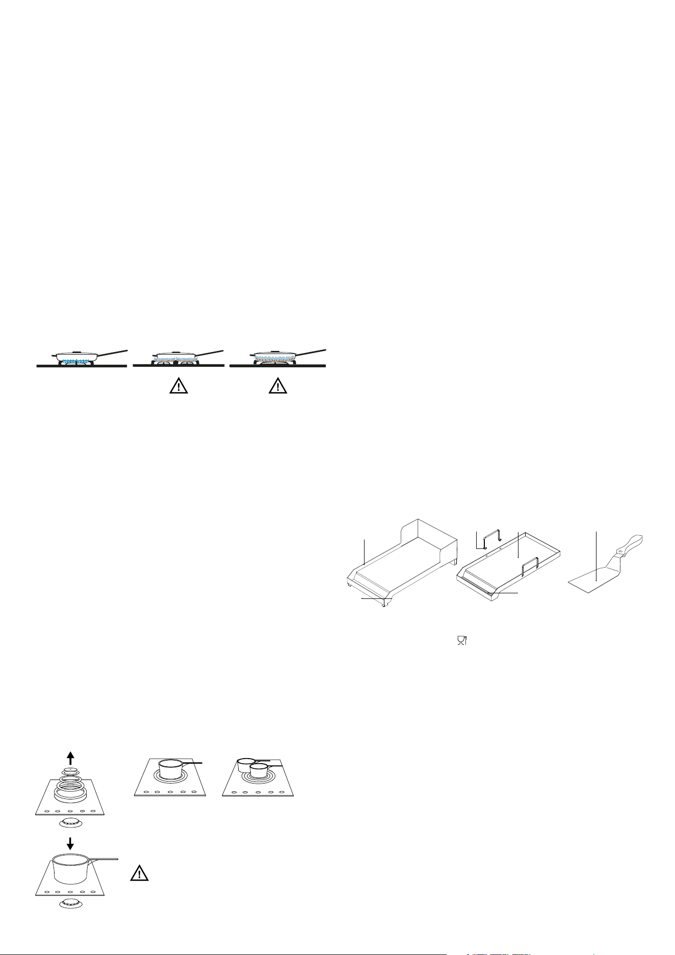
Cookware to use according to burner size
Burners ID Diametro fondo pentola Ø (cm)
Medium SR 10 ÷ 20
Large R 20 ÷ 24
Fish burner P Oval pans (380 x 185)
Ring TC/DCC 22 ÷ 28
Dual ring DUAL 24 ÷ 30
Burner Placement
Always check that the burners are correctly positioned,
ensuring a uniform and quiet flame.
B
C
D
A
Ignition of the burners
The index above the knobs will help you locate the corresponding
burner. Press the knob while rotating it counterclockwise,
preferably to the ignition position. At this point, the spark will
ignite the burner; keep the knob pressed for about 5 seconds
to ensure that the flame stays lit when released (if ignition fails,
repeat the procedure).
Ignition of the DUAL Burner
(Only for certain models)
Identify the knob using the index near the knobs themselves. Press
and rotate the knob to the (maximum) symbol for 5 seconds. Once
the burner is lit, continue rotating the knob counterclockwise until
you reach the first stop, which corresponds to the medium setting. By
applying slight force, you can surpass the first stop, causing the outer
flame ring to turn off, leaving only the small central burner, called the
AUXILIARY burner, lit. To adjust the auxiliary burner to its minimum,
rotate the knob counterclockwise until it reaches the end of its travel.
At this point, to reignite the entire burner, rotate the knob clockwise to
the desired setting.
Burner Right Wrong
Semi-Rapid
(Medium)
Rapid (Large)
Dual ring
Fish burner
Check that the
screws under
the burner are
always properly
tightened.
Symbols Function
Knob
DUAL
(Only for certain models)
Index
O
Maximum
Minimum
Index
O
Maximum
Minimum
7
INSTRUCTIONS FOR USE
Gas hob
Use of the griddle
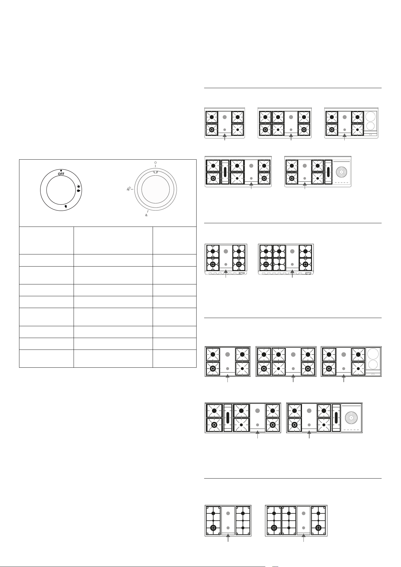
If you wish to use a griddle, please keep the following
precautions in mind:
- The griddle can be preheated at the maximum burner
power for no more than 10 minutes.
- It is recommended to set the cooking power to a lower
setting for food preparation.
- Ensure that the ames from the burner do not extend
beyond the edge of the griddle.
- Maintain a minimum distance of 150 mm from the side
wall to the edge of the griddle.
- Do not place the griddle on multiple burners
simultaneously.
Correct position Incorrect position Incorrect position
Use of the “coup de feu”
Functioning of the appliance
The large “Coup de Feu” cast iron plate with concentric rings
allows you to place the container (or multiple containers)
directly on the surface (fig. B, C). The heating is provided by a
gas burner (fig. A). The plate is designed to provide heat that
is not too intense and is evenly distributed across the surface.
This allows for slow cooking, particularly suitable for sauces
and gravies, browning and grilling, or for heating and keeping
food warm. Switch on the burner 15/20 minutes before use to
allow the cast iron plate to accumulate heat. The plate can then
be used for another 10/15 minutes even with the burner turned
off. The center of the plate is where the highest temperatures
are reached, while the peripheral areas are cooler. By simply
moving the container from the center to the outer areas, you
can achieve varying cooking intensities without adjusting the
flame. If the size of the containers allows, you can cook several
dishes simultaneously (fig. C). When needed, it can also be
used as a practical and spacious countertop.
Cleaning and maintenance
Cleaning should be done when the plate is warm, using common
kitchen products for metal surfaces. Scrub with a steel wool
pad, following the grain of the satin finish. Dry thoroughly and
immediately. If you wish to improve the aesthetic appearance
of the plate, after cleaning, apply a layer of Supercromo paste.
If the plate will not be used for long periods, after the usual
cleaning, apply a thin layer of liquid paraffin (vaseline oil)
with a cotton ball. This treatment is necessary to prevent the
formation of surface oxidation. Upon the next use of the plate,
you may notice a slight evaporation of the paraffin oil, which
will disappear within a few seconds. The plate may sometimes
show signs of surface oxidation due to moisture or, more likely,
because it has not been used for some time. It is recommended
to use the plate regularly to prevent any oxidation. Never leave
the plate wet. If surface oxidation occurs, use a slightly abrasive
paper to remove it, being careful to scrub gently and always
following the grain of the plate’s satin finish.
Do not cook food directly on the surface of the plate.
Always use appropriate cookware.
Use of the gas fry-top
A = cooking zone
B = cooking fat collector
C = fry-top handles
D = spatula
A
A
DC
B
B
The fry-top consists of a stainless steel plate, suitable for
contact with foodi [ ] providing uniform temperature
across the cooking surface with minimal heat loss. To use the
appliance, ignite the flame underneath the plate by turning the
corresponding knobs (see “Ignition of Burners”) and ensure
the flame is present. Set the knob to the maximum position
for about 10 minutes and wait for the plate to heat up. After
this period, the plate is ready to begin cooking. By adjusting
the flame, you will have no limits to your culinary creativity. The
lowest knob setting allows for slow or dietetic cooking, while
faster cooking is ideal for meats, fish, and vegetables. The fry-
top plate is also suitable for oriental dishes when used with an
optional lid, which is necessary for this type of cooking. In some
models, a spatula (D) is provided, which will help you both with
cooking and cleaning the plate.
To achieve maximum efficiency, you
should use a pot with a diameter of at least
26 cm, centered over the opening created
by removing the 5 rings (Fig. A).
Be careful not to spill the contents of
the pot onto the exposed burner.
Fig. C
Fig. B
Fig. A
8
INSTRUCTIONS FOR USE
Gas hob
Cleaning and maintenance
It is recommended to perform a thorough cleaning at the
end of each cooking session. With the plate still warm and
the flame set to low, remove the cooking residues using the
included spatula (D). Pour a small amount of water onto the
plate and continue cleaning with the spatula. Once the water
has completely evaporated, repeat the process several times
until the desired result is achieved. It is extremely important to
carry out the cleaning with the plate still hot.
Knob
A
C
B
A
B
C
Plate
Knob position
( A max - B med - C min )
Time min.
Egg
B 2
Eggplant sliced
(thickness 0.5 cm)
B 5 - 9
Potatoes sliced
B 5 -7
Zucchini sliced
B 5 - 9
Fish (sea bream,
approx. 200 g)
B 15
Hamburger
B 9
Beef steak
B 2-3
Florentine steak
(thickness 2 cm)
A 5
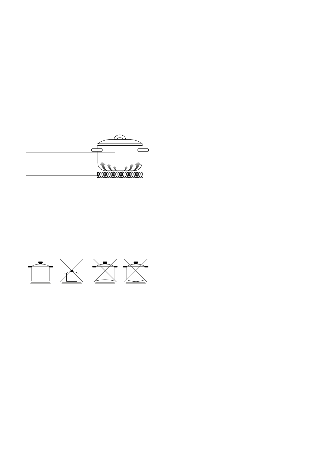
Correct positioning of the fry-top
Majestic
M09F-MD10F M12F
PM09F
P09F-PD09F-PD10F
P36F
L09F-LD09F
LD10F
L12F
P12F P12FI P15FI P15FS
PM12F
M12FI M15FS M15F
M15FS M15F
M09F-MD10F M12F
PM09F
P09F-PD09F-PD10F
P36F
L09F-LD09F
LD10F
L12F
P12F P12FI P15FI P15FS
PM12F
M12FI M15FS M15F
M09F-MD10F M12F M12FI
M09F-MD10F M12F
PM09F
P09F-PD09F-PD10F
P36F
L09F-LD09F
LD10F
L12F
P12F P12FI P15FI P15FS
PM12F
M12FI M15FS M15F
Panoramagic
PM09F PM12F
M09F-MD10F M12F
PM09F
P09F-PD09F-PD10F
P36F
L09F-LD09F
LD10F
L12F
P12F P12FI P15FI P15FS
PM12F
M12FI M15FS M15F
Pro Line
L09F-LD09F
LD10F L12F
M09F-MD10F M12F
PM09F
P09F-PD09F-PD10F
P36F
L09F-LD09F
LD10F
L12F
P12F P12FI P15FI P15FS
PM12F
M12FI M15FS M15F
M09F-MD10F M12F
PM09F
P09F-PD09F-PD10F
P36F
L09F-LD09F
LD10F
L12F
P12F P12FI P15FI P15FS
PM12F
M12FI M15FS M15F
Professional Plus \ Nostalgie
P12F P12FI
P15FS
P09F-PD09F
PD10F-P36F
P15FI
9
INSTRUCTIONS FOR USE
Induction hob
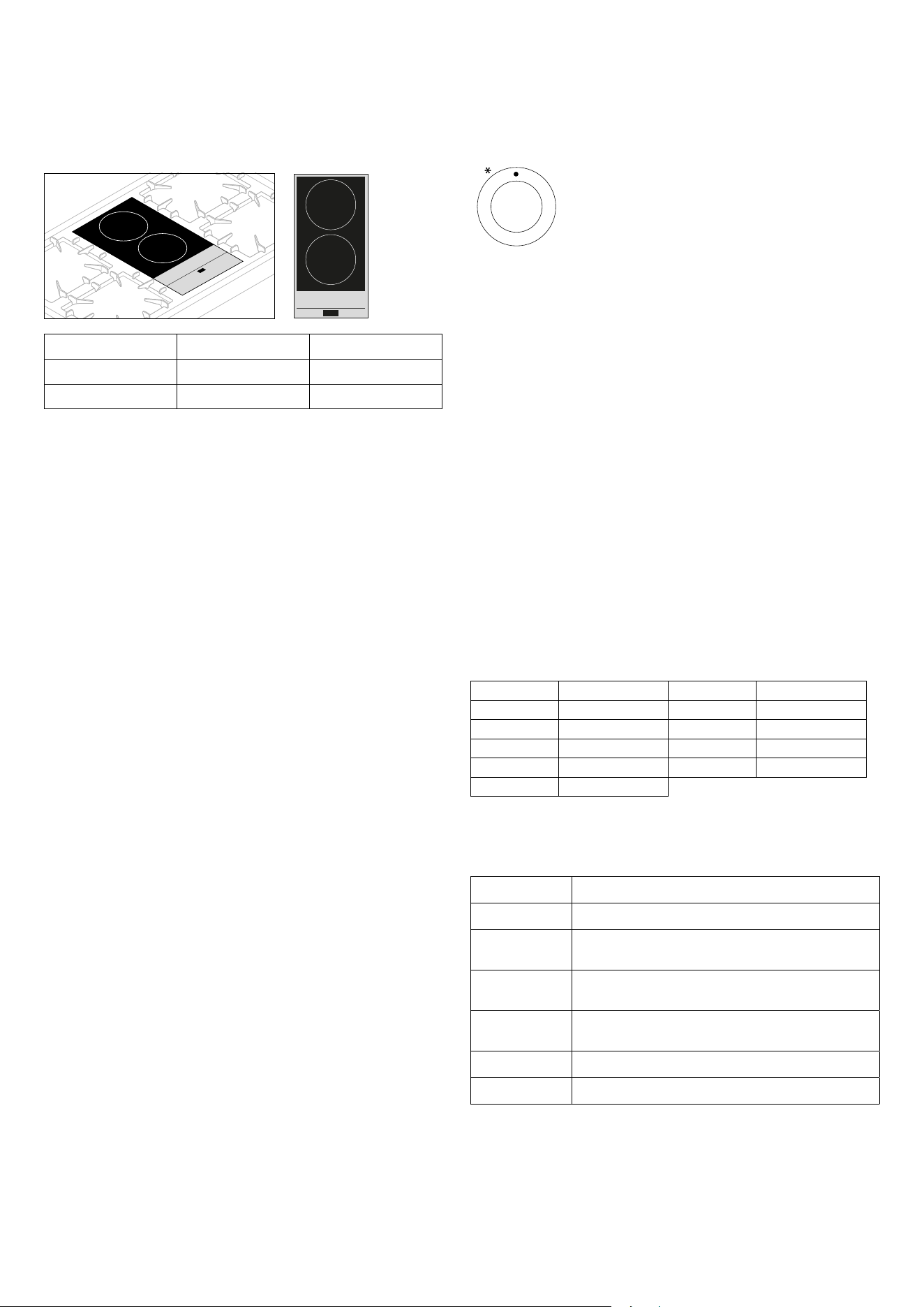
Induction cooking
Under each cooking zone, there is a coil that generates a variable
electromagnetic eld when a pot is placed on it, producing
inductive power on a ferromagnetic material located at the
bottom of the pot. The result is that the bottom of the pot heats
up. The material that makes up the pot is crucial:
- Suitable pots are those with a ferromagnetic base (this
can be checked with a magnet).
- The following types of pots should not be used: copper,
stainless steel, aluminum, glass, wood, ceramic.
Ferromagnetic material
pot
Inductive currents
Electromagnetic coil
Recommended pots and zones
The heat zones are clearly indicated by the circular areas.
When one or more cooking zones are used, the remaining
surface stays cool. Each cooking zone is designed to work with
induction-compatible pots, with a diameter slightly smaller
than the diameter of the selected cooking zone. The bottom
of the pot should be thick and at. Its diameter should closely
match the cooking ring’s diameter. Both the cooking surface
and the bottom of the pot should be kept clean.
- Do not wet or overheat the plates.
- Avoid thermal shocks to the glass-ceramic top. For
example, do not pour cold water onto the hot surface.
- Avoid extending the handles of pots as they may be
accidentally knocked over.
- It is preferable not to cook on the glass-ceramic surface
with pots that have been used on gas burners. The ame
deforms the bottom of the pot.
Pots
Suitable Materials: Stainless steel, enameled steel, cast iron,
ferromagnetic steel, aluminum with a ferromagnetic base.
Unsuitable Materials: Aluminum and steel without a
ferromagnetic base, copper, ceramic, porcelain, glass, brass.
To check the compatibility of the pot, place it with a small amount
of water on the cooking zone. Set the zone to level “9”, and the
water should boil in a few seconds.
Try using a magnet on the bottom of the pot.
Certain pots may generate “noise” during cooking. This
phenomenon does not come from the induction hob and does
not aect cooking performance.
Pot dimensions
The cooking zones automatically adjust to the diameter of the
pots. However, the bottom of these pots must meet a certain
minimum diameter for proper operation. To achieve maximum
eciency, place the pot at the center of the cooking zone.
Ventilation
La ventilazione del piano è completamente automatica. La
vThe ventilation of the hob is fully automatic. The cooling fan
for the electronics under the hob runs at low speed until the
temperature of the electronics increases. When the hob is used
for a longer time, the fan speed increases. Once the electronics
are cool, the cooling fan will stop automatically.
Aer use, the glass-ceramic hob retains heat for an extended
period. Do not leave children near the hob, and do not touch the
surface with your hands. The residual heat indicator will remain
on until the hob cools down.
In case the glass-ceramic hob develops cracks, immediately
disconnect the appliance from the power supply and contact an
authorized technical service center.
10
INSTRUCTIONS FOR USE
Induction hob
Use of the induction plate
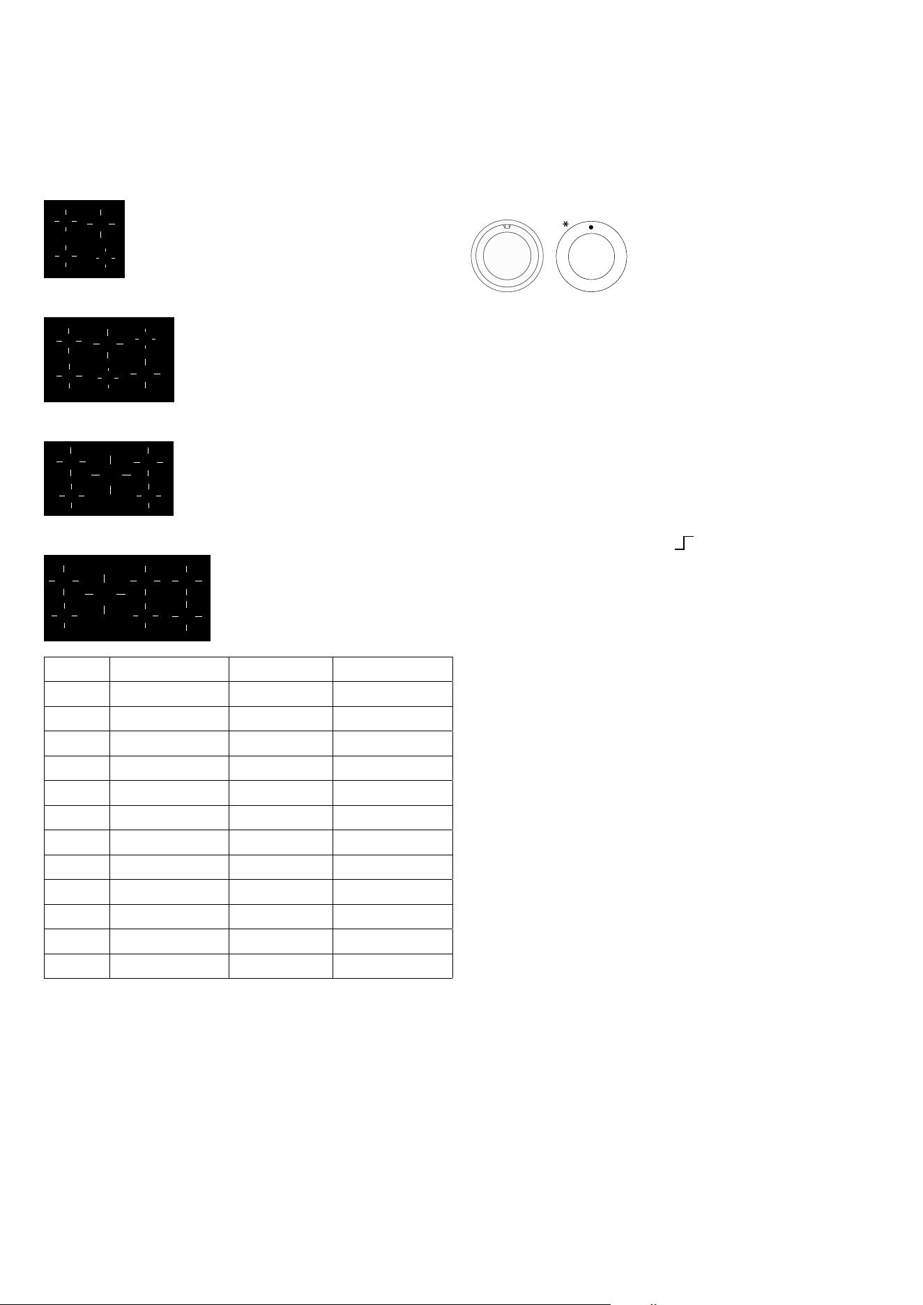
P2
P1
Zone Diameter (mm) Power (watt)
P1 ø 220 1850 W
P2 ø 180 1850 W
Display
- Power level set: (1-9)
- Heat-up: (A)
- Residual heat: (H)
- Pot missing or unsuitable (U)
- Error (E)
First power-on
Clean the surfaces of the hob with a damp cloth.
Turning on a cooking zone
Turn the corresponding knob clockwise. The set power level
(from 1 to 9) will appear on the hob display.
Turning off a cooking zone
A cooking zone is turned o by rotating the corresponding knob
counterclockwise. The display will show [0] for 15 seconds,
aer which it will disappear from the display or switch to the [H]
symbol if the cooking zone is still hot.
Automatic shutoff
The appliance automatically turns o when there are overheating
issues or power error conditions.
Pan detection
Each cooking zone is designed to work with specic induction-
compatible cookware with a diameter smaller than that of the
selected cooking zone. If the pan is unsuitable, the display will
show the pan absence symbol “U,” and the appliance will not
function. It prevents the hob from turning on until a suitable
pot is placed on the cooking zone or an induction-compatible
pan is used. The pan detection lasts for 9 minutes. If no suitable
cookware is placed on the cooking zone during this time, the
zone will turn o.
The zone display changes from the symbol U to [-].
Residual heat indication
If the cooking zone, when turned o, is still very hot, the display
will show the symbol “H.”
HEAT-UP Function
The Heat-up function is available on each cooking
zone. This means that for a dened period of time,
the cooking zone operates at maximum power,
and once this time expires, the power is
automatically reduced to the set level. The
duration of this function depends on the set power level. The
Heat-up function is activated by rotating the knob
counterclockwise from the 0 position to the end stop, as shown
in the gure. As soon as the knob is turned to the le, the display
of the corresponding zone will show [A]. Aer activation, a power
level must be set within 3 seconds for continued cooking; if this
doesn’t happen, the Heat-up function will be interrupted.
KEY-LOCK Function
The Key-lock function is useful in the presence of children.
However, the presence of an adult is still recommended when
the appliance is in use. Activating the Key-lock function turns
o all cooking zones and prevents them from being accidentally
turned on. The Key-lock function is activated, with the knobs
in the 0 position, by rotating one of the induction zone controls
counterclockwise. The display will show [L][L]. Repeating the
same action will deactivate the Key-lock function.
Operation time limitation
Each cooking zone has its own maximum continuous operating
time, which depends on the set power level. If the operation time
limit is reached, the corresponding zone will turn o.
Level Duration (hours) Level Duration (hours)
1 8.5 6 2.5
2 6.5 7 2
3 5 8 1.5
4 4 9 1.5
5 3.5
Approximate power operation time limitation level.
Cooking tips (purely indicative values)
Knob position Type of cooking
1 -2 Melt butter, chocolate, etc.
2 - 3 Heat small amounts of liquids, keep food warm,
prepare sauces.
4 -5 Heat solid foods, defrost frozen foods, omelets
with 2-3 eggs, fruits, and vegetables.
5-6 Cook meat and sh, legumes in sauce, dishes with
water, prepare jams.
6-7 Roast meat or sh, steaks, liver, eggs.
8-9 Boil large quantities of water, fry potatoes, etc.
11
INSTRUCTIONS FOR USE
Induction hob
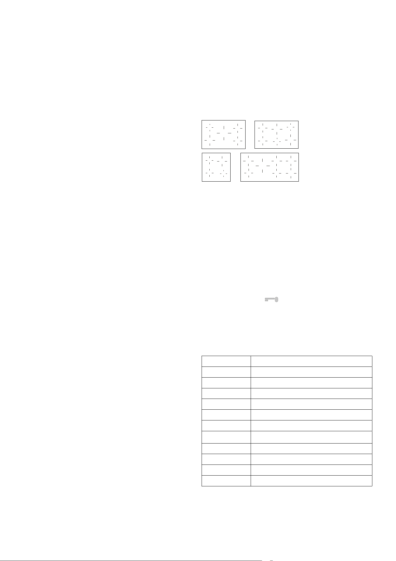
Use of induction hob
Mod. PI06
A
B
B
C
Mod. PDI10 - MDI10 - PI096 - MI096 - PDI096 - PMI09
A
A
B
B
C
C
Mod. LBI095 - LDBI09
E
E
F
E1
G
Mod. PI127 - MI127 - PMI12
I
L
H
I
H
M
M
Zone Diameter (mm) Power (watt) Booster (watt)
A ø 145 1400W 2200W
B ø 180 1850W 3000W
C ø 210 2300W 3700W
D ø 260 2600W 3700W
E ø 160 1100W 1400W
E1 ø 160 1400W 2000W
F ø 200 2300W 3000W
G ø 250 2300W 3000W
H ø 145 1400W 1850W
I ø 200 2300W 3000W
L ø 250 2300W 3000W
M 210X190 2100W 3000W
First power-on
Clean the surface of the hob with a damp cloth.
Knob
The knob has no markings, and the
power level will be visible on the
display.
Display
Each cooking zone is associated with its own display
- Set power level: (1-9)
- Food heating (42°-65°): (U)
- Booster: (P)
- Heat-up: (A)
- Residual heat: (H)
- Pot missing or unsuitable: (U)
- External error: (E)
- Fault: (F)
- Permanent knob rotation: (
)
Turning on a cooking zone
Turn the corresponding knob clockwise. The set power level
(from 1 to 9) will appear on the hob display.
Turning o a cooking zone
A cooking zone is turned o by rotating the corresponding knob
counterclockwise. The display will show [0] for 15 seconds,
aer which it will disappear from the display or change to the
[H] symbol if the cooking zone is still hot.
Automatic shuto
The appliance automatically turns o when overheating
conditions or power errors occur.
Pan detection
Each cooking zone is designed to work with specic induction-
compatible cookware with a diameter just smaller than that of
the selected cooking zone. If the pan is unsuitable, the display
for that zone will show the “pot missing” symbol [U], and the
appliance will not operate. This prevents the hob from turning
on until a suitable pot is placed on the cooking zone or until an
induction-compatible pan is used. If the pot is removed during
operation, the zone will turn o. The pan detection lasts for 10
minutes; if no suitable pot is used on the cooking zone during
this time, the zone will turn o. The zone display changes from
the [U] symbol to the [ - ] symbol.
12
BOOSTER Function
The Booster function is used to provide additional power to
a specic cooking zone in order to reduce the cooking time.
This function is activated by rotating the knob clockwise from
the 0 position (o) to the end stop . Aer a brief audible signal,
the display will show [P], indicating that the Booster function is
activated. The Booster function lasts a maximum of 10 minutes.
Aer this time, the zone will automatically return to power level
[9]. The Booster function ends before the time limit when:
- A lower power level is set.
- The pan is removed.
- An overheating condition occurs in the appliance or the
cooking zone.
The Booster function takes priority over the Heat-up function.
HEAT-UP Function
The Heat-up function, or fast heating, is available on every
cooking zone. This means that for a dened period, the cooking
zone operates at maximum power, and once the time expires,
the power is automatically reduced to the set level. The duration
of this function depends on the set power level. The Heat-up
function is activated by rotating the knob counterclockwise for
2 seconds, from the 0 position, to the end stop. Aer a brief
audible signal, the display for the corresponding zone will
show [A]. Aer activation, a power level must be set within 10
seconds to continue cooking; if this does not happen, the Heat-
up function will be interrupted.
BRIDGE Function
Place the pot in the center of the B+B or M+M zones (see page
26). Rotate both knobs of the two involved zones clockwise
beyond the end stop for 3 seconds, and the Bridge function will
be activated.
Aer activation, the power for both zones can be adjusted
using only the le knob.
Note: The pot used must have a size that covers both centers
of the two zones.
KEEP WARM 42° and 65° Functions
Rotate knob clockwise. Between the o position (0) and the
power position (1), there is the position (u), which activates the
function to keep food warm inside the pot at 42°C.
For 5 and 6-zone models only: Rotate knob further clockwise.
Between position “u” and the power position (1), there is
position “U”, which activates the function to keep food warm
inside the pot at 65°C. The maximum time for both functions
is limited to 120 minutes. Both functions take priority over the
Heat-up function.
INSTRUCTIONS FOR USE
Induction hob
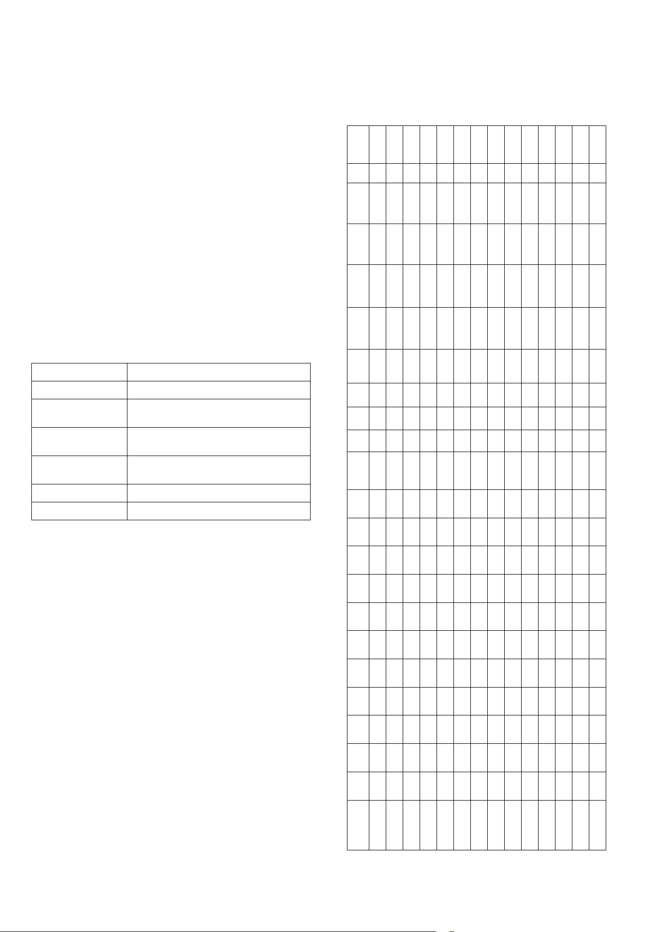
KEY-LOCK Function
The Key-lock function is useful when there are children present.
However, the presence of an adult is still recommended
when the appliance is in operation. Activating the Key-lock
function turns o all cooking zones and prevents them from
being accidentally turned on. Repeating the same action will
deactivate the Key-lock function.
4
6
2
1
3
5
2
3
4
1
5
3
2
1
4
2
3
1
5
4
6
7
- 4-zone models: The Key-lock function is activated, with
the knobs in the 0 position, by rotating the controls for
zones 2 and 3 counterclockwise. Repeating the same
action will deactivate the Key-lock function. The display
will show [O][F]. If a control is rotated with the Key-lock
function active, the display will show [L][L][L][L].
- 5 or 6-zone models: The Key-lock function is activated,
with the knobs in the 0 position, by simultaneously
rotating the controls for zones 1 and 2 counterclockwise.
The display will show [L][L][L][L].
- 7-zone models: The Key-lock function is activated, with
the knobs in the 0 position, by simultaneously rotating the
controls for zones 1, 2, 6, and 7 counterclockwise. The two
displays will show
.
Operation time limitation
Each cooking zone has a maximum continuous operating time.
This depends on the set power level. If the operation time limit is
reached, the corresponding zone will turn o.
Level Duration (ore)
U 2
1 6
2 6
3 5
4 5
5 4
6 1,5
7 1,5
8 1,5
9 1,5
P (10 min. [P], aerwards 80 min. [9])
13
INSTRUCTIONS FOR USE
Induction hob
Power management
Power management, when the Booster function is used, is
carried out as follows: the most recent set cooking level takes
priority over the other zones. The activation of a cooking zone
will not be displayed if a power level that is too high is requested.
In this case, the regular operation will only begin aer reducing
the power level by rotating the knob of the cooking zone
counterclockwise, and the corresponding power level will then
be shown on the display.
Overheating of the cooking zone
If a cooking zone overheats excessively during operation, the
power will be automatically reduced, and the display will show
the newly adjusted power level. At this point, only the power
level can be decreased. Once the temperature of the cooking
zone drops below the critical value, normal cooking can be
resumed.
Recommended cooking programs (purely indicative values)
knob position Type of cooking
1 - 2 Melt butter, chocolate, etc.
2 - 3
Heat small amounts of liquids, keep food warm,
prepare sauces.
4 - 5
Heat solid foods, defrost frozen foods, omelets
with 2-3 eggs, fruits, and vegetables.
5 - 6
Cook meat and sh, legumes in sauce, dishes
with water, prepare jams.
6 - 7 Roast meat or sh, steaks, liver, eggs.
8 - 9 Boil large quantities of water, fry potatoes, etc.
MODELS
A
ø145
B
ø180
C
ø210
D
ø260
E
ø160
E1
ø160
F
ø200
G
ø250
H
ø145
I
ø200
L
ø250
M
210x190
E03E E03 E04E 06E3 06MP 09E3 09MP PM09 WD
kW
QuickSart
PI06 1 2 1 - - - - - - - - - - - - 1 - - - - - 10,60
LBI095... - - - - 2 1 1 1 - - - - - - - - - - 1 - - 10,8
MI096E3 ... 2 2 2 - - - - - - - - - - - - - - 1 - - - 14,5
MI096S3 ... 2 2 2 - - - - - - - - - - - - - - 1 - - 1 15,1
PI096E3 ... 2 2 2 - - - - - - - - - - - - - - 1 - - - 14,5
LDBI09... - - - - 2 1 1 1 - - - - - 1 - - 1 - - - - 12
PDI096E3 ... 2 2 2 - - - - - - - - - 1 - - 1 - - - - - 16,6
MDI10S3 ... 2 2 2 - - - - - - - - - 1 - - 1 - - - - 1 17,2
PI127 ... - - - - - - - - - 2 1 2 1 - - - - 1 - - - 19,85
MI127E3 ... - - - - - - - - - 2 1 2 1 - - - - 1 - - - -
MI127S3 ... - - - - - - - - - 2 1 2 1 - - - - 1 - - - -
PMI09...E3 2 2 1 - - - - - - - - - - - - - - - - 1 - 14,50
PMI09...S3. 2 2 1 - - - - - - - - - - - - - - - - 1 1 15,1
PMI127 ... - - - - - - - - 2 2 1 2 1 - - - - 1 - - 1 20,45
14
INSTRUCTIONS FOR USE
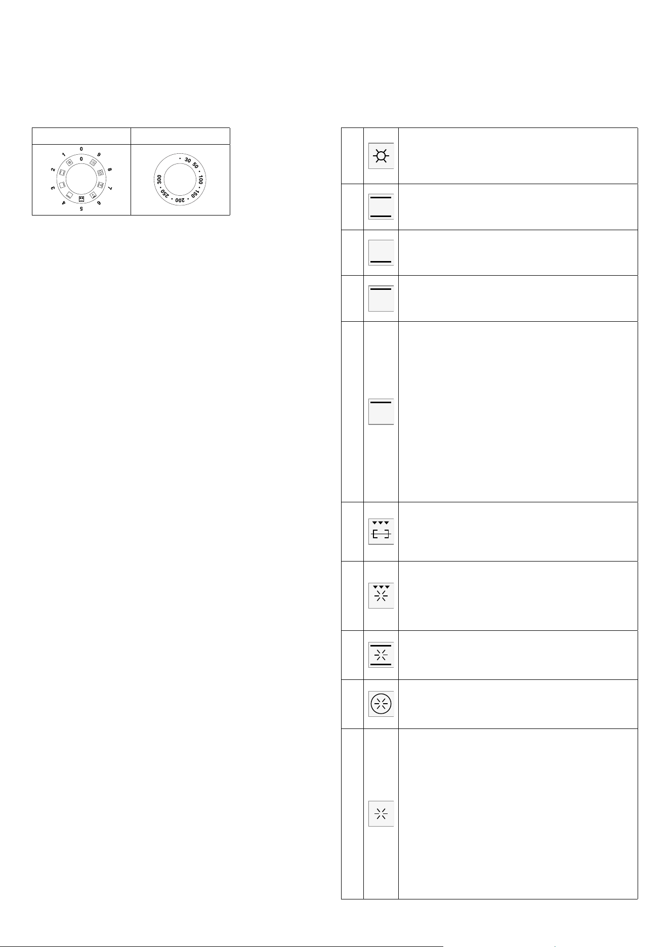
M3 models with 5-button programmer
Description of standard oven controls
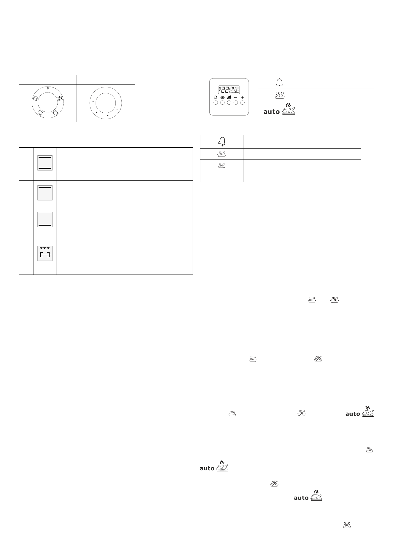
S. Selector T. Thermostat (M3)
S - Electric Multifunction Oven Selector
P - Programmer - Clock - Timer
T - Thermostat
Use of thermostat (T)
This knob allows you to select temperatures from 50°C to
250°C (MP) and from 30°C to 300°C (M3).
Turning on and o
Select one of the cooking functions by rotating the selector (S)
and adjust the temperature with the thermostat (T).
It is recommended to preheat the oven before baking.
Safety thermostat
The oven is equipped with a safety thermostat that
disconnects the electrical supply. The thermostat resets
automatically when the oven temperature drops. To reuse
the oven, simply wait for it to cool down. If the thermostat
is triggered due to a component malfunction, technical
assistance should be contacted.
How to use the multifunction oven
Choose one of the 9 cooking functions by rotating the selector
(S) and adjust the temperature with the thermostat (T). If your
model has a programmer, set it for cooking.
Functions
1
Pizza cooking
This function is particularly suitable for cooking pizza,
focaccia and bread. The main source of heat is from the
bottom heating element that works in combination with the
oven’s other resistances.
2
Normal static cooking
Is the oven’s classic function particularly suited to cooking
the following foods: pork chops, sausages, cod, braised beef,
game, roast veal, meringues and biscuits, baked fruit, etc.
3
Cooking from underneath
This is the most suitable form to nish food cooking, in
particular confectionery (biscuits, meringues, leavened
cakes, fruit desserts, etc.) and other foods.
4
Cooking from above
Especially suitable for browning and to give the nal touch
of colour to many foods; it is recommended for hamburgers,
pork chops, veal steaks, sole, cuttlesh, etc.
4a
Eco cooking (M3)
It is the function that allows you to cook with a considerable
saving on electricity consumption. To make the most of
this feature it is useful, before inserting the ECO function,
to introduce the dish inside the oven, positioning it in the
center of the cavity. With the Eco function, cooking times
adapt to slow cooking such as: braised meats, white meats,
baked pasta, delicate pastries. This cooking cycle is not
recommended for frozen foods. To select Eco cooking turn
the selector knob “S” to position 8 and then, when the word
“ON” appears on the display, hold down the “+” key of the
programmer for about 2 seconds until the display shows
the message “ECHO”. With Eco cooking the programmable
temperature ranges from a minimum of 30 ° C up to a
maximum of 300 ° C.
Note: Eco cooking cannot be selected with the meat probe
inserted.
5
Closed door grill cooking
The suitable function for fast and deep grilling, to brown and
roast meats in general, llet steaks, Florentine steaks, grilled
sh and also grilled vegetables. Cooking with the electric grill
must be made with the thermostat at 180 °C closed door.
6
Fan grill cooking
Particularly fast and deep with signicant energy savings,
this function is suitable for many foods such as pork chops,
sausages, pork or mixed spits, game, gnocchi alla romana,
etc. Cooking with the electric grill must be made with the
thermostat at 180 °C closed door.
7
Intensive cooking
Is the quick and intense cooking function for various dishes;
best for: baked sh, braised vegetables, spits, duck, chicken,
etc.
8
Multiple fan cooking
Is the function that allows simultaneous cooking of dierent
dishes without the smells blending; you can cook lasagne,
pizza, croissants and brioches, tarts, cakes, etc.
9
•
•
•
•
•
•
•
•
•
•
•
•
Quick Start
This function is used to speed up the preheating of your
oven. We suggest you use this function when setting a
cooking temperature between 200 and 250° C. Using the
QuickStart function for temperatures below 200° C does not
oer particular advantages. To use the Quick Start function,
turn the selector knob (S) until it is positioned on the symbol
(9), then set the desired temperature with the thermostat
knob (T). Once the oven has reached the temperature, the
orange thermostat light goes o and the oven is ready to
receive the food to be cooked. At this point, set the desired
cooking function.
CAUTION: the Quick Start function is not suited to cooking
food, it only serves to preheat the oven more quickly.
DO NOT USE THE QUICK START FUNCTION FOR MORE
THAN 20 MINUTES.
15
INSTRUCTIONS FOR USE
M3 models with 5-button programmer
Static electric oven
S. Selector T. Thermostat
OFF
0
250
200
150
100
50
Functions
1
Normal static cooking
Is the oven’s classic function particularly suited to cooking
the following foods: pork chops, sausages, cod, braised
beef, game, roast veal, meringues and biscuits, baked fruit,
etc.
2
Cooking from above
Especially suitable for browning and to give the nal touch
of colour to many foods; it is recommended for hamburgers,
pork chops, veal steaks, sole, cuttlesh, etc.
3
Cooking from underneath
This is the most suitable form to nish food cooking, in
particular confectionery (biscuits, meringues, leavened
cakes, fruit desserts, etc.) and other foods.
4
Closed door grill cooking
The suitable function for fast and deep grilling, to brown
and roast meats in general, llet steaks, Florentine steaks,
grilled sh and also grilled vegetables. Cooking with the
electric grill must be made with the thermostat at 180 °C
closed door.
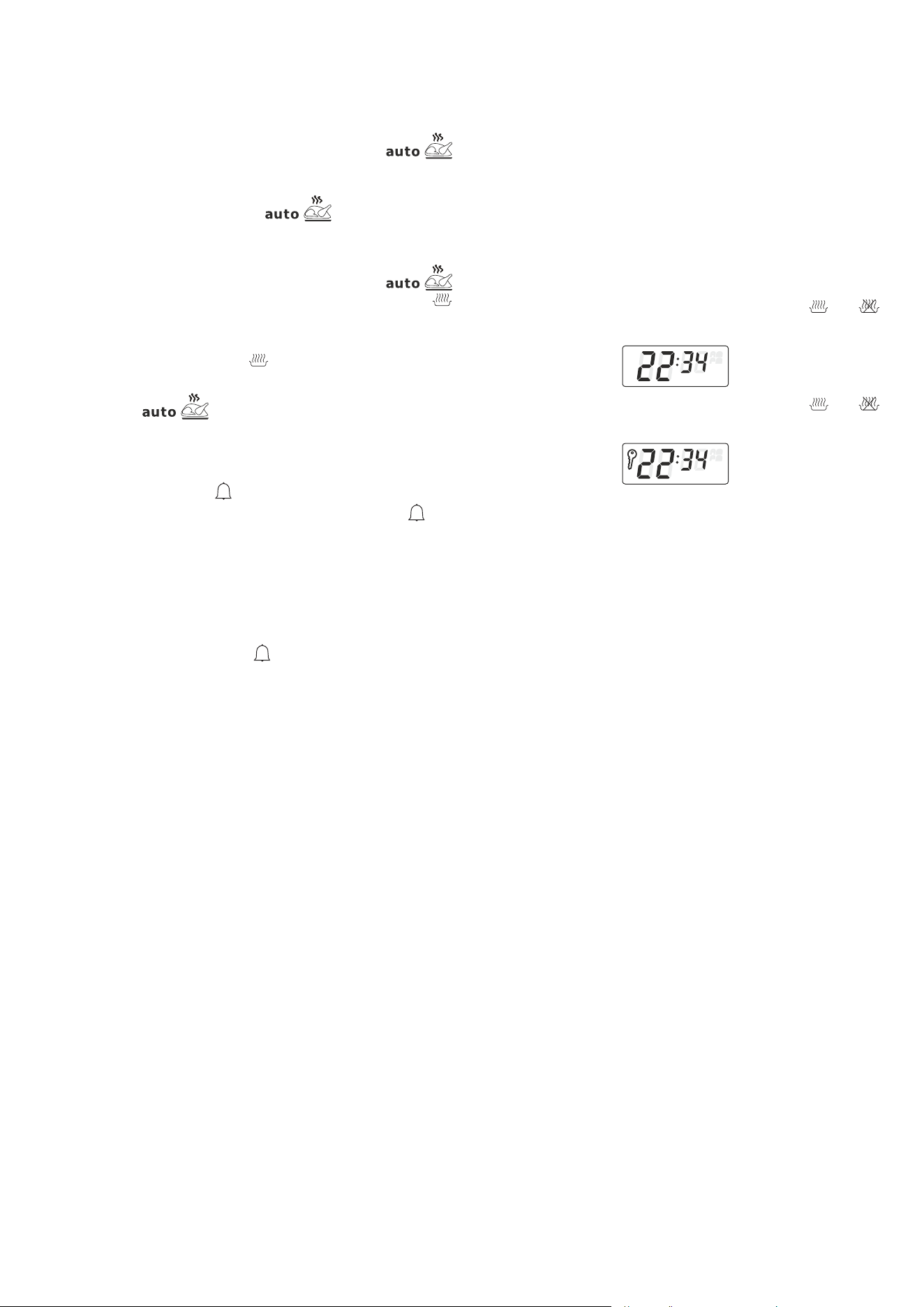
5-Button programmer
A
[–]/[+]
Timer
A
[–]/[+]
Duration and manual function
Automatic program
Display
Timer
A
[–]/[+]
Automatic cooking duration
A
[–]/[+]
Setting cooking end time
A
[–]/[+]
Decrease / Increase the selected parameter
Standby mode
Time to reach stand-by mode: 1 minute.
Power consumption in stand-by with information: 0.8W.
Function setting
Select the desired function by pressing the corresponding
button and set the time using the +/- keys.
Appliance operation
When the control is powered on for the rst time, the display
shows a ashing clock that increments by one unit every minute.
Follow the procedure described in the “Clock Setting” section
below. By simultaneously pressing the
A
[–]/[+]
and
A
[–]/[+]
buttons, the
appliance enters the “Manual Mode”. The temperature can be
set using the thermostat knob (T), and the desired function can
be selected using the selector switch (S).
Clock setting
The clock function is activated by simultaneously pressing the
cooking duration
A
[–]/[+]
and end of cooking
A
[–]/[+]
. buttons.
The time can then be set using the +/- keys. Any previously set
programs will be automatically cancelled.
Manual mode
This mode is activated by simultaneously pressing the cooking
duration
A
[–]/[+]
and end of cooking
A
[–]/[+]
buttons. The
symbol will turn o. Any previously set programs will be deleted.
Semi-automatic function with cooking duration
Turn on the oven, select the cooking duration function (
A
[–]/[+]
button) and set the desired time using the +/- keys. The
symbols will appear on the display. When the current
time matches the calculated end time (which can be checked
using the end of cooking
A
[–]/[+]
button), the oven will switch o. An
acoustic signal will sound, and the
symbol will ash.
Semi-automatic function with end of cooking time
Turn on the oven, select the end of cooking function (
A
[–]/[+]
button),
16
INSTRUCTIONS FOR USE
M3 models with 5-button programmer
and set the desired end time using the +/- keys. The
symbols will appear on the display. When the current time
reaches the programmed end time, the oven will switch o. An
acoustic signal will sound, and the
symbol will ash.
Semi-automatic function with cooking duration and end time
Turn on the oven, select the cooking duration function (
button), and set the desired time using the +/- keys. The
A
[–]/[+]
symbol will appear on the display. Wait a few seconds until the
current time is displayed. Then set the end of cooking time by
pressing the end of cooking (
A
[–]/[+]
) button and adjusting with
the +/- keys. The oven will switch o at the end of the automatic
program. The
symbol will ash, and the acoustic
signal will sound.
Timer
Select the timer function (
A
[–]/[+]
button), and set the desired time
using the +/- keys. During countdown, the bell symbol
A
[–]/[+]
will
remain lit. When the countdown reaches zero, the acoustic
signal will sound.
Acoustic signal
The acoustic signal activates at the end of the cooking duration
or minute minder functions and remains active for 7 minutes. It
can be silenced by pressing the
A
[–]/[+]
button. The signal’s volume
can be adjusted by pressing the “-” key without selecting any
function beforehand. Three sound levels are available, and the
selected volume depends on how long the “-” button is held.
Starting a program and monitoring
Once a program has been selected, it starts aer the time has
been set. The remaining time can be viewed at any moment by
re-selecting the corresponding function.
Cancelling a program
A program can be cancelled by selecting the manual mode
function. At the end of an automatic program, it will be cleared
automatically.
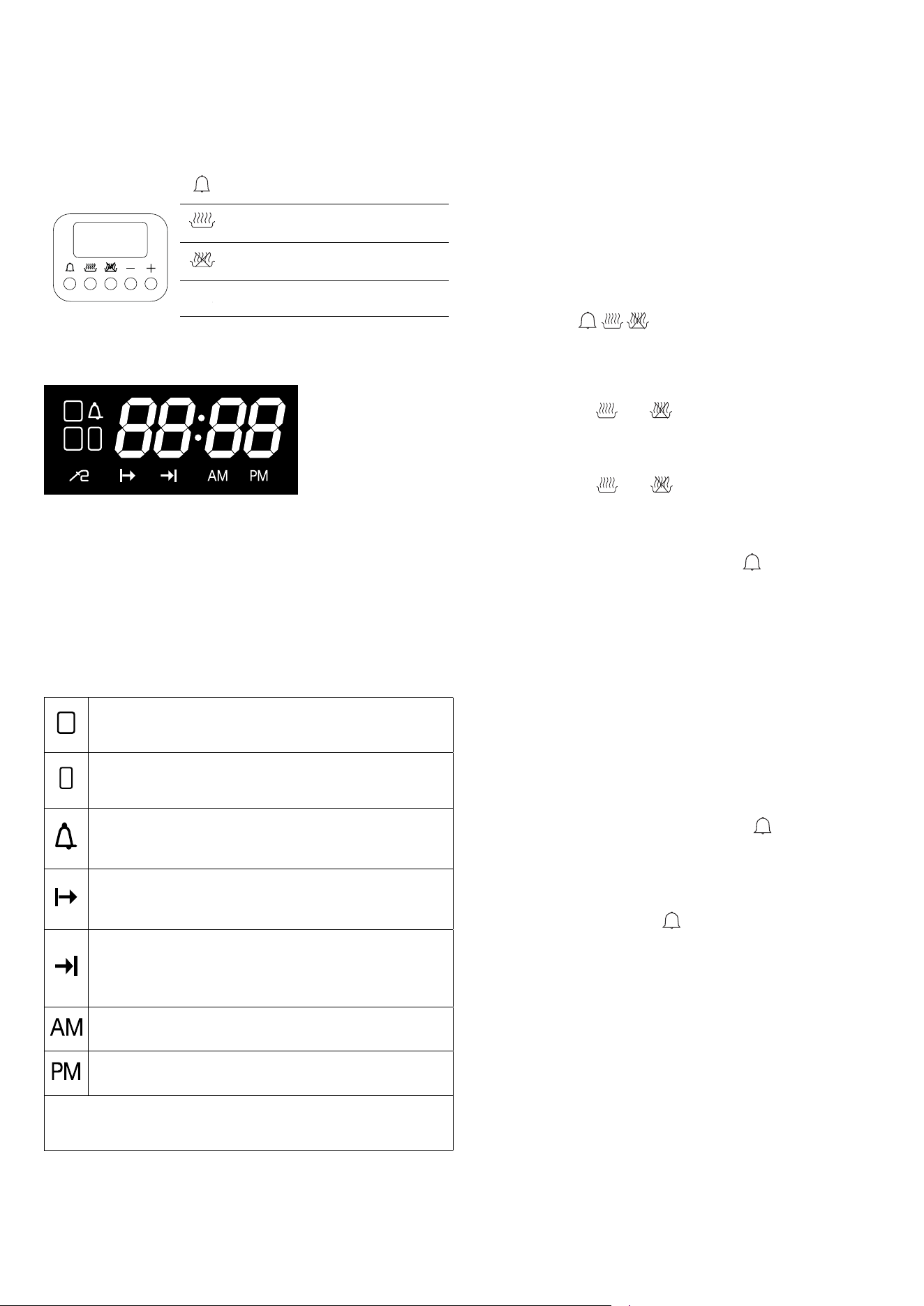
Child lock
All buttons are locked and the oven becomes inactive. This
prevents children from accidentally operating the appliance.
Note: To deactivate the child lock, press and hold the
A
[–]/[+]
and
A
[–]/[+]
buttons for 3 seconds until the key symbol disappears.
To activate the child lock function, press and hold the
A
[–]/[+]
and
A
[–]/[+]
buttons for 3 seconds.
The key symbol will appear on the display (child lock active).
Clock mode (12/24-hour format)
You can switch between 24-hour and 12-hour (AM/PM) clock
display by pressing and holding the
+ button for 3 seconds.
17
INSTRUCTIONS FOR USE
E3 models with 5-button programmer
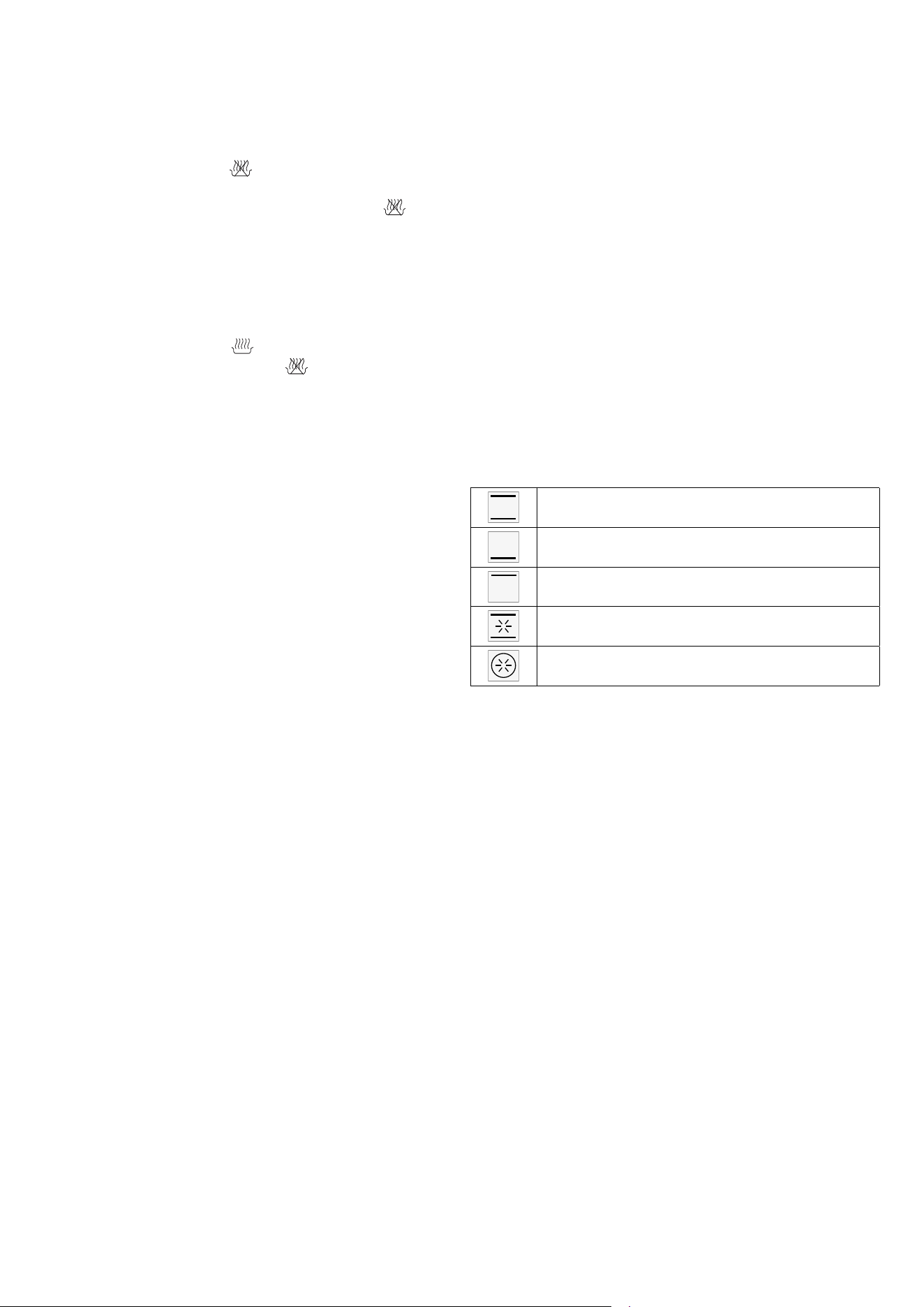
5-Button programmer
A
[–]/[+]
Timer setting
A
[–]/[+]
Set cooking start time
A
[–]/[+]
Set cooking end time
A
[–]/[+]
Decreases the selected parameter
A
[–]/[+]
Increases the selected parameter
Display
It consists of 4 digits and indicates:
- In stand-by: the current time.
- During manual cooking: the set temperature.
- During time-based automatic cooking: the set temperature.
- During cooking with meat probe: the probe temperature.
- With the timer function active and the oven in stand-by: the
current time.
Icons
1
Main Oven Icon [1]. If ashing, the display shows the
temperature and cooking duration settings for the main
oven (only for double oven models).*
2
Secondary Oven Icon [2]. If ashing, the display shows
the temperature and cooking duration settings for the
secondary oven (only for double oven models).*
If illuminated, it indicates that the minute minder is active.
If ashing, it indicates that the minute minder has ended.
During minute minder setting, the icon ashes.
If illuminated, it indicates that the oven is operating in
delayed start mode. The icon remains lit throughout the
delay period.
If illuminated, it indicates that the oven is operating in
automatic end-of-cooking mode. During the delayed start
period, the icon ashes and becomes steadily lit once
cooking begins.
If illuminated, it indicates that the clock is in 12-hour AM
mode.
If illuminated, it indicates that the clock is in 12-hour PM
mode.
(*) When both ovens are in use, press the corresponding thermo-
stat knob to view the temperature and cooking duration settings for
the main or secondary oven.
Standby mode
Timing for reaching low power mode: 1 min.
Power consumption in stand by with information: O,8
Appliance operation
At first power-up, the display shows a flashing clock that
increases by one unit every minute. The oven remains locked,
and can be unlocked in one of the following ways: Set the time
using the [+] and [-] buttons (see “Clock Setting” procedure).
Alternatively, turning on the oven directly accepts the current
clock value as-is. Detailed procedures for setting the clock,
minute minder, cooking duration, and end of cooking time
are provided in the following sections. By pressing one of the
setting buttons (
A
[–]/[+]
,
A
[–]/[+]
,
A
[–]/[+]
), the appliance enters edit mode
(indicated by a flashing display), where the [+] and [-] buttons
can be used to adjust the value. If no button is pressed for 4
seconds, the value is automatically confirmed, and the display
returns to a steady (non-flashing) state. To cancel all settings,
press and hold the
A
[–]/[+]
and
A
[–]/[+]
buttons simultaneously.
Clock setting
Press and hold the
A
[–]/[+]
and
A
[–]/[+]
buttons simultaneously for
5 seconds — the display will begin flashing. Adjust the time
using the [+] and [-] buttons. Clock adjustment is only allowed
when the oven is in standby mode. To change the time format
(12h/24h), during clock setting press the
A
[–]/[+]
button for 4
seconds. Use the [+] button to choose between 24-hour
format or 12-hour format (AM/PM).
Turning the oven on and off
Turn the function selector [S]. The display will show “On”. After 2
seconds, the internal oven light turns on, and the display shows
the default temperature for the selected cooking function. To turn
the oven off during cooking, return the selector to position [0]. The
display will show “OFF”.
Timer
This function operates independently of the oven’s heating
elements and is always available. Press the
A
[–]/[+]
button. The bell
symbol lights up, and the display shows “0’ 00”. Set the desired
time (up to 180 minutes) using the [+] and [-] buttons. If no
changes are made within 4 seconds, the time is saved and the bell
symbol remains steadily lit. To return to clock mode after setting
the minute minder, press the
A
[–]/[+]
button again — the new value
will be confirmed. When the countdown reaches zero, an acoustic
signal is emitted, and the bell symbol flashes. To stop the signal
and flashing, press any button.
Manual operation with unlimited time
Turn on the oven. Select a desired cooking function. Use the
thermostat knob [T] to set the desired temperature. After 4
seconds without further adjustment, the oven starts cooking with
no time limit, and the selected temperature remains displayed.
18
INSTRUCTIONS FOR USE
E3 models with 5-button programmer
Semi-automatic end of cooking operation
Turn on the oven. Press the
A
[–]/[+]
button, and the display shows
“End.” Set the end of cooking time using the [+] and [-] buttons
(the maximum cooking time is 10 hours). Press the
A
[–]/[+]
button
after adjusting the time to return to clock mode, accepting the
newly set value. After 4 seconds of inactivity, the oven starts
cooking for the set time. Once the programmed time is reached,
the oven enters end of cooking mode.
Automatic operation
Turn on the oven. Press the
A
[–]/[+]
button, and set the start time
using the [+] and [-] buttons. Press the
A
[–]/[+]
button, and the display
shows “End.” Set the end of cooking time using the [+] and [-]
buttons. If no cooking time is selected, the oven remains in manual
operation with unlimited time. After 4 seconds of inactivity, the
oven starts cooking until the specified time is reached. You can
always select a cooking function from the available options, and
the temperature can be adjusted. Once the programmed time is
reached, the oven enters end of cooking mode. This function is
not available with the grill and fan grill cooking programs.
End of cooking mode
At the end of time-based cooking, the oven switches off all
heating elements, a triple intermittent acoustic signal of medium
intensity is activated, and the display shows the time. The cavity
symbol flashes. To unlock the oven, simply press any button on
the programmer: the acoustic signal stops, and the oven is ready
to receive new commands.
Cooking temperature selection
The maximum temperature varies depending on the t ype of function.
Upon turning on the oven, a default temperature is proposed for
each function: the cooking temperature can be modified. By
slightly rotating the [T] knob clockwise, the temperature increases
(in increments of 5°C), and counterclockwise, it decreases (in
increments of 5°C). During temperature adjustment (flashing
display), the unit of measurement can be changed from °C to °F
and vice versa by holding the [T] knob for 8 seconds.
Oven light control
After the oven is turned on, the light remains on for 1 minute, and
at the end of preheating, it turns on again for 1 minute. During the
waiting phase of a delayed start, the oven light remains off. The
oven light can always be turned on by pressing the [T] knob, and it
will turn off automatically after 1 minute. During cooking, the light
can be left on continuously by pressing the [T] knob for 3 seconds.
Child safety lock
The oven is equipped with a safety device that prevents unintended
or accidental starting. To activate the safety lock with the oven off,
press and hold the [T] knob for 5 seconds. A short acoustic signal
will sound, and the display will show the symbol “n—0”. In this
state, it is impossible to start the oven. To deactivate the previously
set safety lock, press and hold the [T] knob for 5 seconds.
Cooking inspection
If it is necessary to inspect the food during cooking, the oven door
can be opened. In this case, the lights turn on, and the cooking
process is paused. When the door is closed again, the previously
set function is reactivated.
Dry/Wet cooking *
The oven is equipped with an automatic device that allows
cooking condensation vapors to be expelled from the oven
during certain functions, resulting in dry cooking. If the cooking
process requires moisture to remain inside the oven, moisture
cooking, the automatic device can be disabled by performing the
following operation: after selecting the desired cooking function,
when the display shows [ON], press and hold the “-” button on
the programmer for about 2 seconds until the display shows
[HUM]. This choice allows you to switch between dry cooking and
moisture cooking at your preference. The functions affected are:
Normal Static Cooking *
Bottom Heat Cooking *
Top Heat Cooking *
Intensive Cooking *
Multiple Fan Cooking *
Cooking with Probe (available only on certain models)
Note: Cooking with the probe cannot be used in the “DEFROST,”
“QUICK START,” “PIZZA,” and “ECO” functions.
With the oven in stand-by, insert the meat probe into the
appropriate connection socket, which is usually located on the
left wall of the oven. The display will show “MEAt” for 2 seconds,
and the probe symbol will start flashing. Then, the default probe
temperature value (75°C) will appear on the display. Turn and
then press the control knob to select the desired end cooking
temperature between the two limits of 40°C and 100°C (internal
temperature of the food). After 4 seconds from the last setting,
the chosen temperature will be stored, and the probe symbol
will remain lit. Turn on the oven, select the cooking function, and
set the desired temperature using the appropriate knobs. The
temperature read by the probe will then appear on the display.
When the programmed probe temperature is reached, the oven
will turn off, an audible signal will sound, “End” will flash on the
display, and the oven will switch to “cooking finished” mode.
During cooking, it is always possible to modify the probe
temperature by pressing the knob 3 times and then turning the
control knob.
Note: If the probe is inserted into the connection socket during
cooking, the oven will turn off, and “Off” will appear on the display.
If the probe is removed from the socket during cooking, the oven
will turn off, and “Off” will appear on the display.
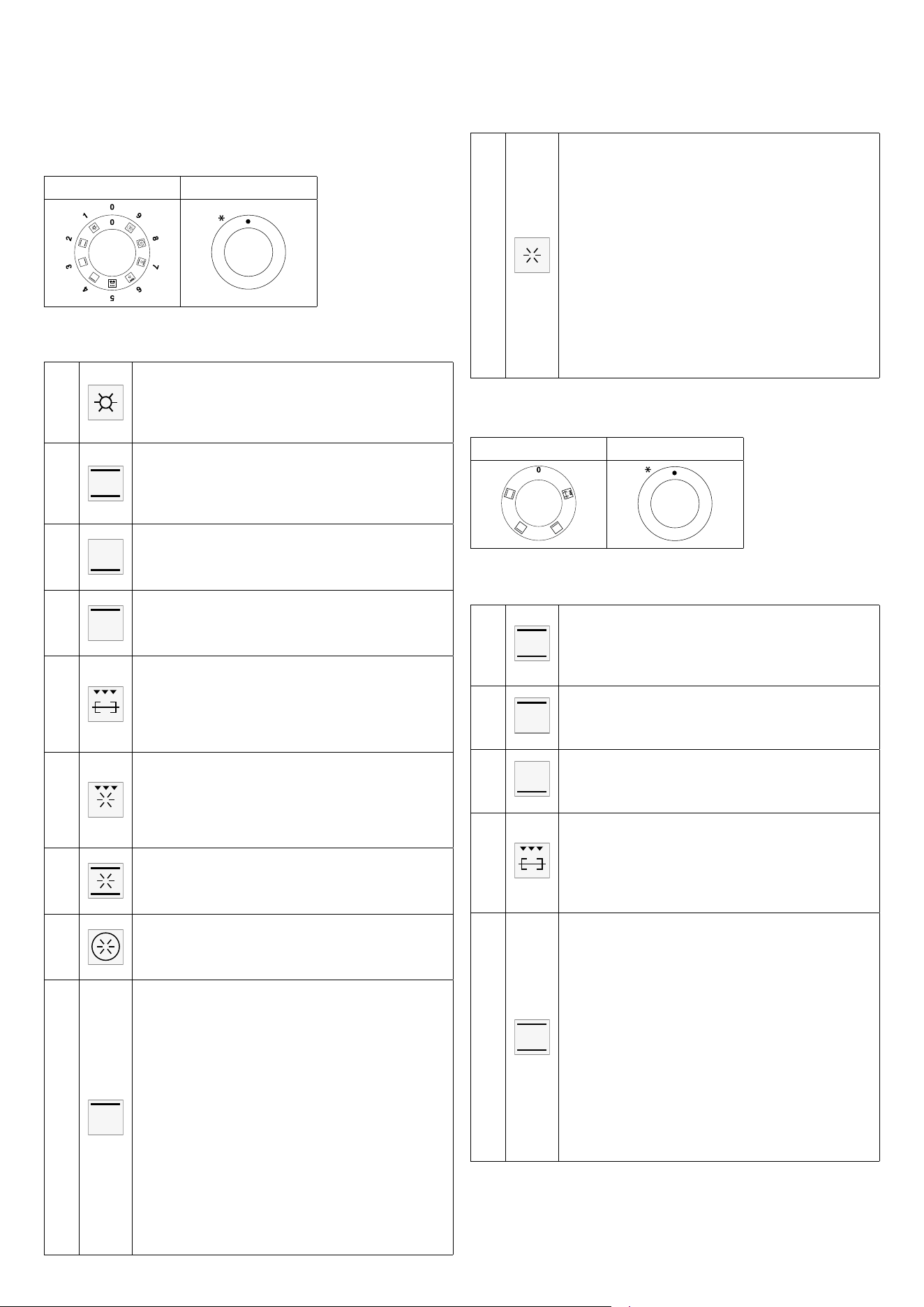
19
INSTRUCTIONS FOR USE
E3 models with 5-button programmer
Multifunction electric oven
S. Selector T. Thermostat
Functions
1
Pizza cooking
This function is particularly suitable for cooking pizza,
focaccia and bread. The main source of heat is from the
bottom heating element that works in combination with the
oven’s other resistances.
2
Normal static cooking * (dry/Wet)
Is the oven’s classic function particularly suited to cooking
the following foods: pork chops, sausages, cod, braised
beef, game, roast veal, meringues and biscuits, baked fruit,
etc.
3
Cooking from underneath * (dry/Wet)
This is the most suitable form to nish food cooking, in
particular confectionery (biscuits, meringues, leavened
cakes, fruit desserts, etc.) and other foods.
4
Cooking from above * (dry/Wet)
Especially suitable for browning and to give the nal touch
of colour to many foods; it is recommended for hamburgers,
pork chops, veal steaks, sole, cuttle sh, etc.
5
Closed door grill cooking
The suitable function for fast and deep grilling, to brown
and roast meats in general, llet steaks, Florentine steaks,
grilled sh and also grilled vegetables. Cooking with the
electric grill must be made with the thermostat at 180 °C
closed door.
6
Fan grill cooking
Particularly fast and deep with signicant energy savings,
this function is suitable for many foods such as pork chops,
sausages, pork or mixed spits, game, gnocchi alla romana,
etc. Cooking with the electric grill must be made with the
thermostat at 180 °C closed door.
7
Intensive cooking * (dry/Wet)
Is the quick and intense cooking function for various
dishes; best for: baked sh, braised vegetables, spits, duck,
chicken, etc.
8
Multiple fan cooking * (dry/Wet)
Is the function that allows simultaneous cooking of dierent
dishes without the smells blending; you can cook lasagne,
pizza, croissants and brioches, tarts, cakes, etc.
8a
Eco cooking
It is the function that allows you to cook with a considerable
saving on electricity consumption. To make the most of
this feature it is useful, before inserting the ECO function,
to introduce the dish inside the oven, positioning it in the
center of the cavity.
With the Eco function, cooking times adapt to slow cooking
such as: braised meats, white meats, baked pasta, delicate
pastries. This cooking cycle is not recommended for frozen
foods.
To select Eco cooking turn the selector knob “S” to position
8 and then, when the word “ON” appears on the display,
hold down the “+” key of the programmer for about 2
seconds until the display shows the message “ECHO”. With
Eco cooking the programmable temperature ranges from a
minimum of 30 ° C up to a maximum of 300 ° C.
Note: Eco cooking cannot be selected with the meat probe
inserted.
9
•
•
•
•
•
•
•
•
•
•
•
•
Quick Start
This function is used to speed up the preheating of your
oven. We suggest you use this function when setting a
cooking temperature between 200 and 250° C. Using the
QuickStart function for temperatures below 200° C does
not oer particular advantages. To use the Quick Start
function, turn the selector knob (S) until it is positioned
on the symbol (9), then set the desired temperature with
the thermostat knob (T). Once the oven has reached the
temperature, the orange thermostat light goes o and the
oven is ready to receive the food to be cooked. At this point,
set the desired cooking function.
CAUTION: the Quick Start function is not suited to cooking
food, it only serves to preheat the oven more quickly.
DO NOT USE THE QUICK START FUNCTION FOR MORE
THAN 20 MINUTES.
Static oven
S. Selector T. Thermostat
OFF
Functions
1
Normal static cooking
Is the oven’s classic function particularly suited to cooking
the following foods: pork chops, sausages, cod, braised
beef, game, roast veal, meringues and biscuits, baked fruit,
etc.
2
Cooking from above
Especially suitable for browning and to give the nal touch
of colour to many foods; it is recommended for hamburgers,
pork chops, veal steaks, sole, cuttlesh, etc.
3
Cooking from underneath
This is the most suitable form to nish food cooking, in
particular confectionery (biscuits, meringues, leavened
cakes, fruit desserts, etc.) and other foods.
4
Closed door grill cooking
The suitable function for fast and deep grilling, to brown
and roast meats in general, llet steaks, Florentine steaks,
grilled sh and also grilled vegetables. Cooking with the
electric grill must be made with the thermostat at 180 °C
closed door.
5
Eco cooking
It is the function that allows you to cook with a considerable
saving on electricity consumption. To make the most of it
this feature is useful, before inserting the ECO function,
introduce the dish inside the oven placing it in the center
of the cavity. With the Eco function, cooking times adapt
to slow cooking such as: braised meat, white meat, baked
pasta, delicate pastry. This cooking cycle is not recommen-
ded for frozen foods.
To select Eco cooking turn the selector knob “S” to posi-
tion 1 and then, when the display shows “ON”, hold down
the “+” key of the programmer for about 2 seconds until
the appearance on the display of the word “ECO”. With Eco
cooking the programmable temperature goes from a mini-
mum of 30 ° C up to a maximum of 250 ° C.
20
IMPORTANT: Introduce the food when the oven is preheated.
Grill cooking
For appliances with an electric grill, cooking is done with the door closed at 180°C. The food to be grilled should be placed on
the corresponding grill, preferably on the fourth rack.
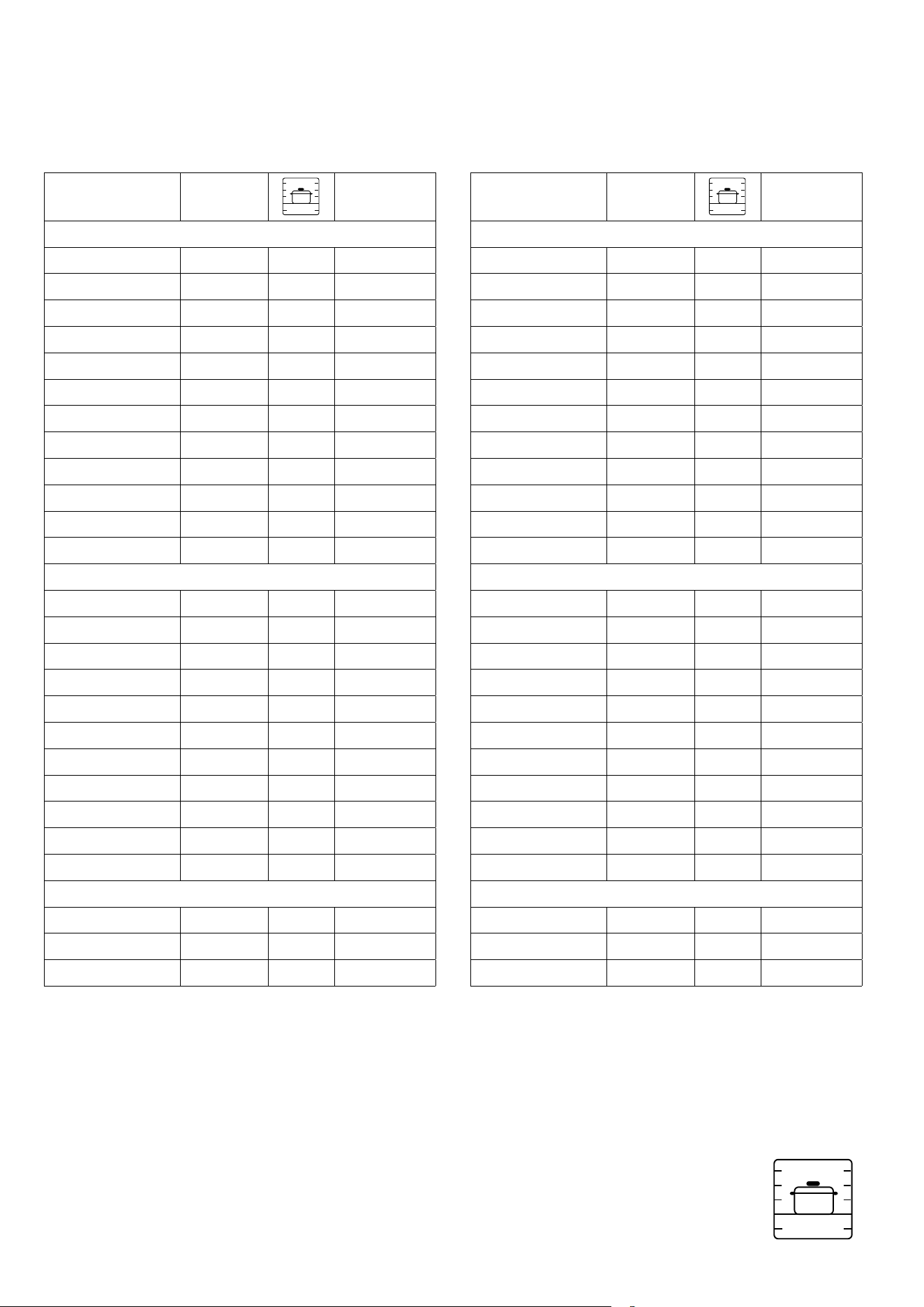
Rack positions
There are 5 rack positions – position 1 is the lowest, and position 5 is the highest, close to the grill. If
cooking a single dish, use rack position 3. If cooking multiple trays, depending on the height of the tray or
the food, it is recommended to cook on rack positions 2 and 4. Use rack positions 4 and 5 for grilling and
the grill pan on the bottom rack position 1 to catch any drips. The bottom rack position 1 can be used to
slow down cooking or to reduce the temperature.
Convection oven (indicative values)
DISH TEMP (°C)
4
3
2
1
5
TIME (MIN)
MEATS
Roast beef 170/180 2/3 40/50
Roast ox 170/190 2/3 40/60
Roast veal 160/180 2/3 65/90
Roast lamb 140/160 2 100/130
Rare roast beef 180/190 2/3 40/45
Roast hare 170/180 2/3 80/100
Roast rabbit 160/170 2 80/100
Roast turkey 160/170 2 160/240
Roast goose 160/180 2/3 120/160
Roast duck 170/180 2/3 100/160
Roast chicken 180 2/3 90/120
FISH 160/180 2/3 15/25
PATISSERIE
Fruit cake 180/200 2 40/50
Margherita cake 180/190 2 40/45
Brioches 170/180 2 40/60
Sponge cake 190/200 2 25/35
Donuts 160/180 2 35/45
Sweet pu pastry 180/200 2 20/30
Grape atbread 190/200 2 30/40
Strudel 160 2 25/35
Savoiardi biscuits 150/180 2 50/60
Apple fritters 180/200 2 18/25
Savoiardi pudding 170/180 2 30/40
BAKERY
Bread 180/200 3 45
Pizza 250 3 10/20
Toast 185/195 2 7
Static oven (indicative values)
DISH TEMP (°C)
4
3
2
1
5
TIME (MIN)
MEATS
Roast beef 225 2/3 60/80
Roast ox 250 2/3 50/60
Roast veal 225 2/3 60/80
Roast lamb 225 2 40/50
Rare roast beef 230 2/3 50/60
Roast hare 250 2/3 40/50
Roast rabbit 250 2 40/50
Roast turkey 250 2 50/60
Roast goose 225 2/3 60/70
Roast duck 250 2/3 45/60
Roast chicken 250 2/3 40/45
FISH 200/225 1/2 15/25
PATISSERIE
Fruit cake 225 2 35/40
Margherita cake 175/200 2 50/60
Brioches 175/200 2 25/30
Sponge cake 220/250 2 20/30
Donuts 180/200 2 30/40
Sweet pu pastry 200/220 2 15/20
Grape atbread 250 2 25/35
Strudel 180 2 20/30
Savoiardi biscuits 180/200 2 40/50
Apple fritters 200/220 2 15/20
Savoiardi pudding 200/220 2 20/30
BAKERY
Bread 220 3 30
Pizza 250 3 10/20
Toast 250 3 5
4
3
2
1
5
INSTRUCTIONS FOR USE
Cooking charts

21
IMPORTANT: Always insert the thermometer up to the handle so that the tip is in the center of the roast, not near the bone or in
the fatty part.
DISH TEMP (°C)
Beef
Roast beef - Rare beef tenderloin
40-45
Roast beef - Well-done beef tenderloin
50-55
Roastbeef - Filetto di manzo ben cotto 60-65
Roast beef
80-85
Pork
Pork loin
65-70
Roast pork
80-85
Pork shoulder, pork shank
80-85
Pork chop
75-80
Boneless cutlet
70
Cured pork chop (Kassler)
65-70
Meatloaf
70-75
Veal
Roast veal
70-75
Roast veal with kidneys
75-80
Veal foot
80-85
Game meat
Game meat
75-80
Loin
60-70
Rare tenderloin
40-45
Medium tenderloin
50-55
Well-done tenderloin
60-65
Lamb
80-85
Roast
70-75
Poultry
85-90
Fish
85-90
INSTRUCTIONS FOR USE
Cooking charts
22
INSTRUCTIONS FOR USE
Accessories
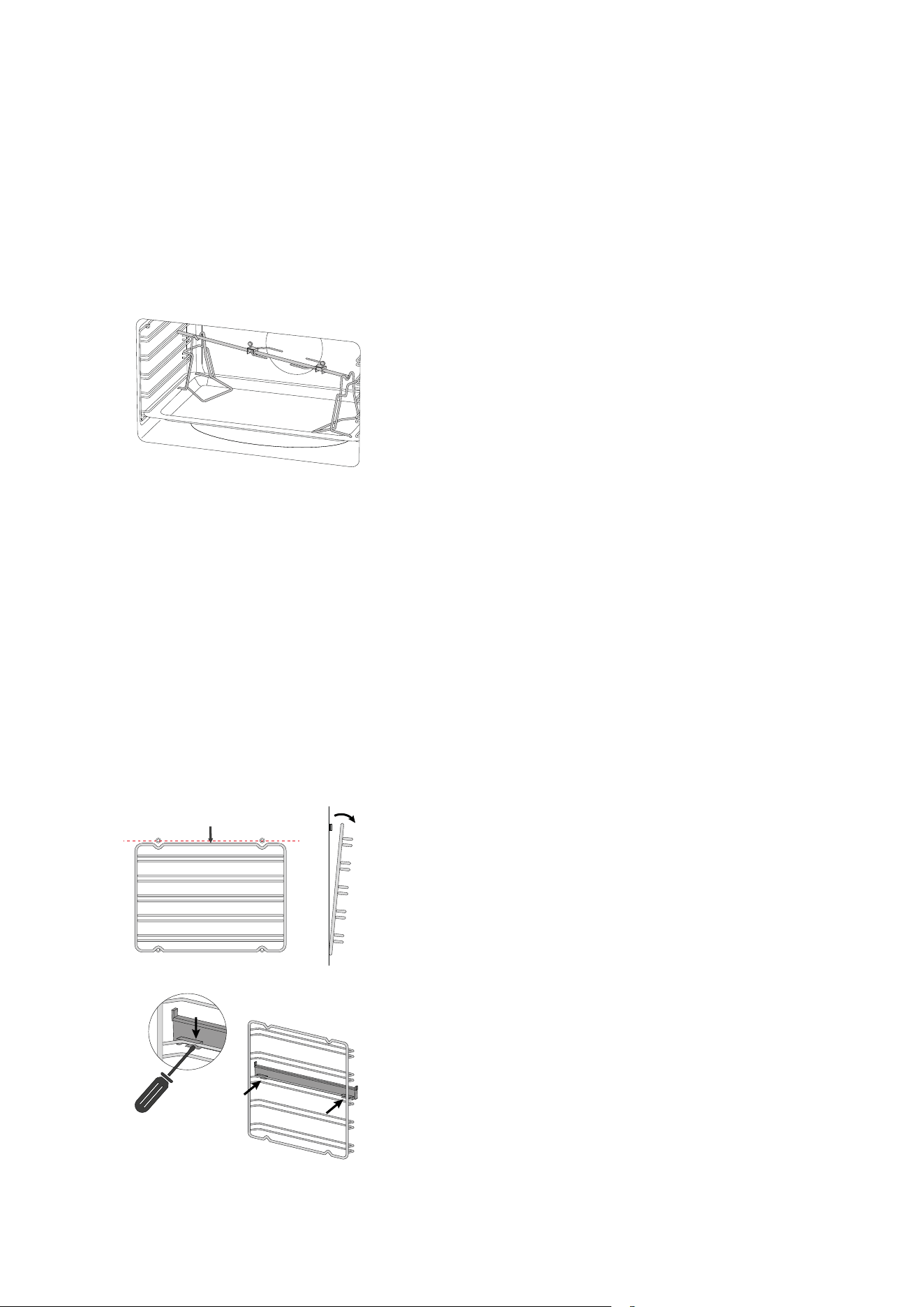
Use of the rotisserie spit
(available only in some models)
Slide the meat onto the spit rod, securing it with the appropriate
forks. Place the rod onto the rotisserie supports previously
inserted into the drip tray, and insert it into the rotisserie motor
sha. Turn on the static grill function with the door closed. To
remove the spit along with the drip tray, pull it out just enough to
allow for complete extraction.
Telescopic guides
(available only in some models)
This solution is designed to enhance ergonomics, practicality,
and safety when handling trays and pans in the oven. The kit
consists of fully extendable side rails that slide on ball bearings
to facilitate the removal and placement of trays. The rails are
anti-tip for added safety. They can be removed for cleaning or
repositioned, as shown in the photos below.
1. Pull down the part highlighted in red to remove it from the
oven wall.
2. Turn them over and place them on a at surface with the
sliding guide side facing down..
3. To release the clip, loosen it with a athead screwdriver..
4. Repeat the steps in reverse to reposition the guide..
Warm drawer
(available only in some models)
WARNING: Do not leave plastic/synthetic or easily inflammable
objects inside the drawer. When the appliance is turned on,
these objects or materials could melt and catch fire (fire hazard).
Do not sit or step on the drawer: this will help prevent injury or
damage to the appliance.
Setting
After selecting the heated drawer icon on the display, the
corresponding screen for setting the operating parameters
will appear. Here, you can select the temperature to heat the
dishes between 30°C and 80°C. Additionally, you can select
the heating duration.
First use
Before using the appliance, clean the drawer following the
instructions in the “Cleaning and Maintenance” section. Then,
turn on the heated drawer for at least 2 hours, selecting the
maximum temperature. The resulting unpleasant odor is
inevitable. Both the odor and any smoke that may form will
dissipate shortly.
Optimal temperature for dish groups
40°C - For cups and glasses
With this setting, the contents of cups and glasses do not cool
quickly, and they can still be removed from the drawer without
burning yourself.
60°C - Ideal for plates and serving dishes.
Food served on heated plates will stay warm longer. In any
case, the plates can still be touched safely.
Heating times
Several factors influence the heating times:
- Material and thickness of the dishes
- Position of the dishes
- Ambient temperature
Therefore, precise heating times cannot be provided. However,
as a reference, here are some useful times:
Quantity: Dishes for 6 people / Time (minutes) 30-35
With frequent use of the drawer, it will be easier to identify the
appropriate times and temperatures for heating dishes.
WARNING! The surfaces of the drawer can become hot during
operation..
23
CLEANING AND MAINTENANCE
Removing the door
To facilitate intensive cleaning of the oven, it is practical to
remove the door by following these instructions:
1. Open the door
2. Move the latch C to the hinge section D following the
steps:
3. Unscrew the screw (only for some models)
4. Remove the door
1
3
C
D
2
4
Lamp Replacement
If the oven light is not working, disconnect the appliance from
the power supply, remove the protective glass of the lamp, and
replace the bulb. It is important to ensure that the replacement
bulb is suitable for high-temperature use and has the necessary
specications for such an application.
1. Loosen with a athead screwdriver
2. Remove the lamp cover glass
3. Remove the lamp:
4. Replace and close it:
1
3
2
4
Disassembly and cleaning of the glass
The oven door is made up of three glass panels. The cleaning
of the glass parts is done using non-abrasive kitchen paper
and a common detergent. Do not use rough abrasive materials
or sharp metal scrapers to clean the oven glass doors as they
may scratch the surface and cause the glass to break. The
inner glass panels are removable (the middle glass should
be correctly repositioned with the THERMOSTOP writing
readable, as shown in gure 3) to make cleaning easier. To do
this, it is necessary to disassemble the oven door.
ATTENTION: Any operation should always be carried out with
the door removed from the oven and placed on a suitable
surface to avoid damaging the front of the door. The middle
glass must be correctly inserted with the THERMOSTOP label
readable, as shown in the following images:
1. Unscrew the 2 screws on the right/left side of the top strip
2. Li the top glass and slide it out
3. Slide out the middle glass
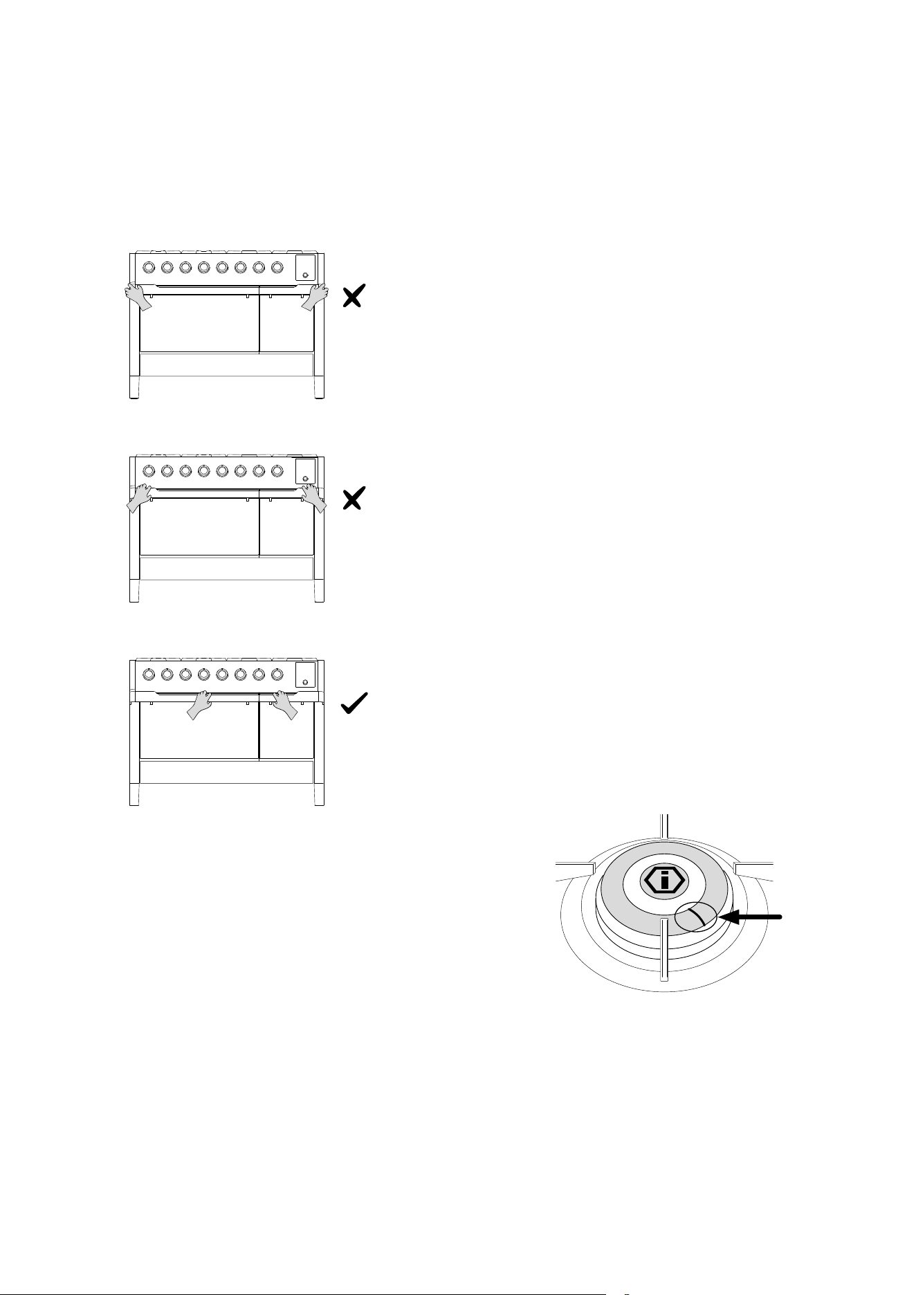
24
CLEANING AND MAINTENANCE
Opening and closing the door (Panoramagic)
WARNING! To avoid physical injury, it is recommended to grasp
the handle when opening and closing the door, as shown in the
following images.
Total black burners
WARNING! The burners are coated with a nanotechnology
treatment.
To preserve the quality of the coating, specic cleaning and
washing methods are recommended.
- Allow the product to cool to room temperature before
cleaning. It is advised not to immerse it in cold water when
still hot.
- Clean with warm water and a minimal amount of neutral
detergent. Wipe with a cloth, preferably made of natural
cellulose, or a non-abrasive sponge.
- Do not use powders, steel wool, abrasive cloths, or
sponges.
- Do not allow food to burn on the burner. In such cases,
stains or discoloration may appear on the surface. These
marks do not aect the functionality of the product, and
in some cases, they can be removed using the following
procedure: immerse the product in warm water with
detergent, gently scrub with a cloth, preferably made
of natural cellulose, and avoid using abrasive cloths or
sponges. For more stubborn stains, it is advisable to heat
white vinegar and scrub as described above.
- Avoid leaving burners in contact with food for long
periods, especially if acidic, such as tomato sauce.
- Avoid contact with metal objects. If necessary, use
wooden or plastic items.
- Avoid dishwasher washing, as part of the product is not
coated and would be irreparably damaged.
- In case of malfunction, ensure that the holes of the outer
crown are always perfectly clean.
- For the correct operation of the DUAL burner, keep the
ignition channel clean as highlighted in the image below.

25
Before performing any cleaning operation, disconnect the appliance from the power supply and close the main gas valve to the
appliance. The worktop should only be cleaned once it has cooled down.
OVEN
COMPONENT CLEANING METHOD WARNINGS
Oven interior
It is recommended to clean the oven aer each use.
Dirt is easier to clean if it is prevented from burning at
high temperatures repeatedly. Remove all removable
parts and wash them separately with warm water and
non-abrasive detergent. Clean the cooking cavity with
a so cloth soaked in a solution of warm water and
ammonia, then rinse and dry.
Do not use steam cleaners for cleaning the oven interior. Do
not use abrasive/corrosive detergents or sharp metal tools to
clean the oven’s glass door, as they may damage the surface
and cause it to break.
Tray
Soak in a solution of warm water and mild soap. Dry
aer washing.
Remove food residues immediately aer use.
Racks
Clean with hot water and non-abrasive detergents or
with a suitable degreaser.
In case of baked-on and hardened dirt, it is recommended to
soak the racks for a few hours before cleaning.
FRONT PANEL
COMPONENT CLEANING METHOD WARNINGS
Stainless steel/
glass surface
Clean the details with lukewarm water and non-
corrosive liquid detergent, then dry them with a so
cloth or microber cloth.
Shine is maintained through periodic cleaning with
specic products typically available on the market. Never
use abrasive powders.
Painted surfaces
To maintain the characteristics of the painted parts,
it is necessary to clean them frequently with soapy
water.
Avoid leaving acidic or alkaline substances (vinegar, lemon
juice, salt, tomato juice, etc.) on the painted parts, and do
not wash the painted surfaces while they are still hot.
HOB
COMPONENT CLEANING METHOD WARNINGS
Stainless steel
surface
Clean the components with lukewarm water and a
non-corrosive liquid detergent, then dry them with a
so or microber cloth.
Shine is maintained through regular cleaning with
appropriate commercial products. Never use abrasive
powders.
Enamelled surface
To maintain the characteristics of the enamelled
parts, they should be cleaned frequently with soapy
water.
Avoid leaving acidic or alkaline substances (vinegar, lemon
juice, salt, tomato juice, etc.) on the enamelled parts and do
not clean when the enamelled parts are still hot.
Hob grids
Remove the grids and clean them with lukewarm
water and a non-abrasive detergent. Carefully remove
any encrustations. Dry them before placing them
back on the hob.
Acidic substances such as lemon juice or other acidic
detergents can irreparably damage the enamel on the grids.
Dry the grids carefully with a cloth immediately aer washing.
Dishwasher cleaning is not recommended.
Glow plugs and
thermocouples
Clean them with a damp cloth. Any dry residue
should be removed with a wooden stick or a pin.
Ignition candles and thermocouples should always be
checked and cleaned periodically.
Crowns, ame
spreader, and caps
The ame spreaders and caps are removable for
easier cleaning. Wash them in hot water with a non-
abrasive detergent.
Carefully remove any encrustations and wait for them to be
completely dry. In case of malfunction, ensure that the holes
in the outer crown are always perfectly clean.
Induction hob
Remove light stains with a damp cloth and then dry
with a dry cloth.
Do not clean with corrosive or abrasive products. Do not use
any items that could damage the ceramic glass hob. Ensure
that the bottom of the pot is dry and clean, and that the glass
surface is free of powders. Moving the pot could scratch the
glass. Immediately remove any sugar, jelly, or jam residues to
prevent damage to the glass.
CLEANING AND MAINTENANCE
Cleaning tips for the oven and front panel
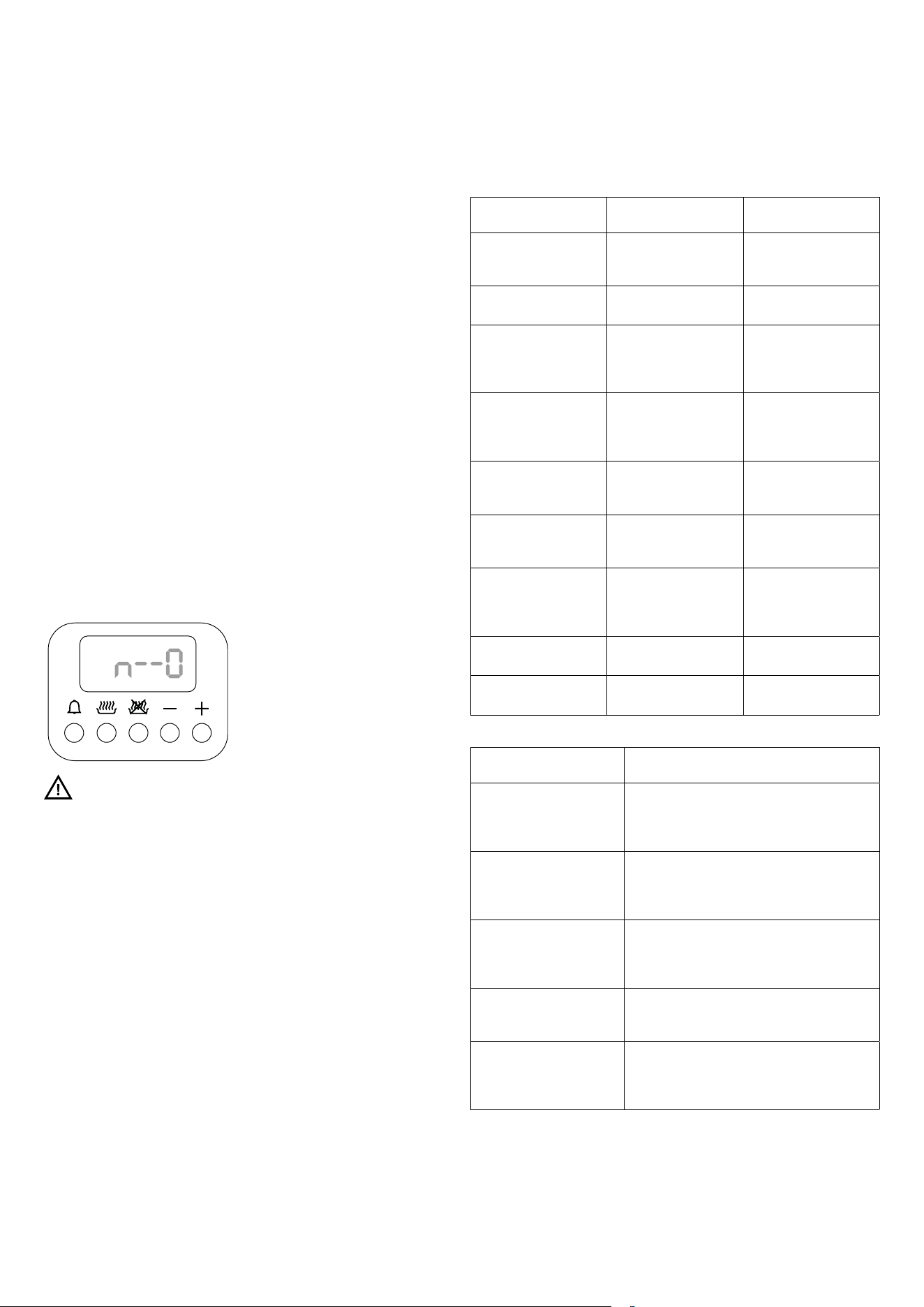
26
TROUBLESHOOTING
Generic problems
Attention
- During the warranty period, repairs can only be carried
out by an authorized Service Center or by using the
appropriate switch.
- Before performing any repairs, disconnect the appliance
from the electrical network, meaning unplug the power
cord or use the appropriate switch.
- Unauthorized interventions and repairs can cause electric
shock or short circuits, so do not attempt them. Leave
such work to authorized technicians.
- In the case of minor issues, you may try to resolve the
problem by following the instructions provided.
- Service assistance during the warranty period is not free if
the appliance malfunction is due to incorrect usage.
- Faults or complaints caused by improper use or
installation will not be repaired under warranty. Warranty
costs will be borne by the user.
Child lock
Symbol representing the child lock
ATTENTION: If this symbol appears on your oven, do not
worry. It may have been accidentally activated. The oven is
equipped with a safety device that prevents accidental or
unwanted operation by children.
How to deactivate
To deactivate the previously activated safety, press and hold
the temperature control thermostat knob for 5 seconds. The
display will show “n—o” followed by “OFF.”
How to activate
How to activate: To activate the safety feature, press and hold
the temperature control thermostat knob (T) for 5 seconds
with the oven turned off.
A short beep will sound, and the display will show “n—o”
followed by “ON.”
The oven will then be locked and cannot be started.
Small issues solvable without the help of a
specialized technician
PROBLEM POSSIBLE CAUSE RESOLUTION
The ame is not
uniform.
Improper gas
adjustment.
The gas adjustment
must be checked by an
expert.
The ame suddenly
changes.
Burner parts are not
positioned correctly.
Correctly position the
burner parts.
To ignite the burners,
the ignition knob must
be held down for a
longer time.
Burner parts are not
positioned correctly.
Correctly position the
burner parts.
Aer ignition, the ame
goes out.
The knob was not
pressed long enough
or was pressed too
gently.
Hold the knob for a
longer period before
releasing it, press rmly.
The grate in the burner
area has changed color.
A natural phenomenon
due to high
temperature.
Clean the grill with
metal cleaner.
Electrical operation,
in general, appears
disturbed.
Igniter or terminal
block damaged.
Check the igniter and/
or terminal block and
replace it if damaged.
The electric ignition no
longer works.
Food or detergent
residue between the
ignition electrode and
the burner.
Carefully clean between
the ignition electrode
and the burner.
The burner caps are
dirty.
Normal dirt.
Clean the burner caps
with metal cleaner.
The display does not
respond to commands.
Touchscreen display
locked.
Open and close the
oven door.
ANOMALIES CAUSES
The appliance and cooking
zone do not turn on.
- The hob has not been correctly connected
to the power supply.
- The protection fuse is blown.
- The KEY-LOCK function is activated.
The symbol “U” appears on
the display.
- The pot has not been placed on the cooking
zone.
- The pot is not compatible with induction.
- The diameter of the pot’s base is too small.
The symbol “E” appears on
the display.
- The electronic system is defective.
- Disconnect the hob from the electrical
network.
- Contact the authorized service center.
The cooking zones do not
function.
- The safety system is activated.
- The pot is empty, and the bottom has
overheated.
If the ventilation remains
active when the hob is o.
- This is not a fault. The fan continues to
operate to protect the electronics.
- The automatic ventilation will stop
automatically.
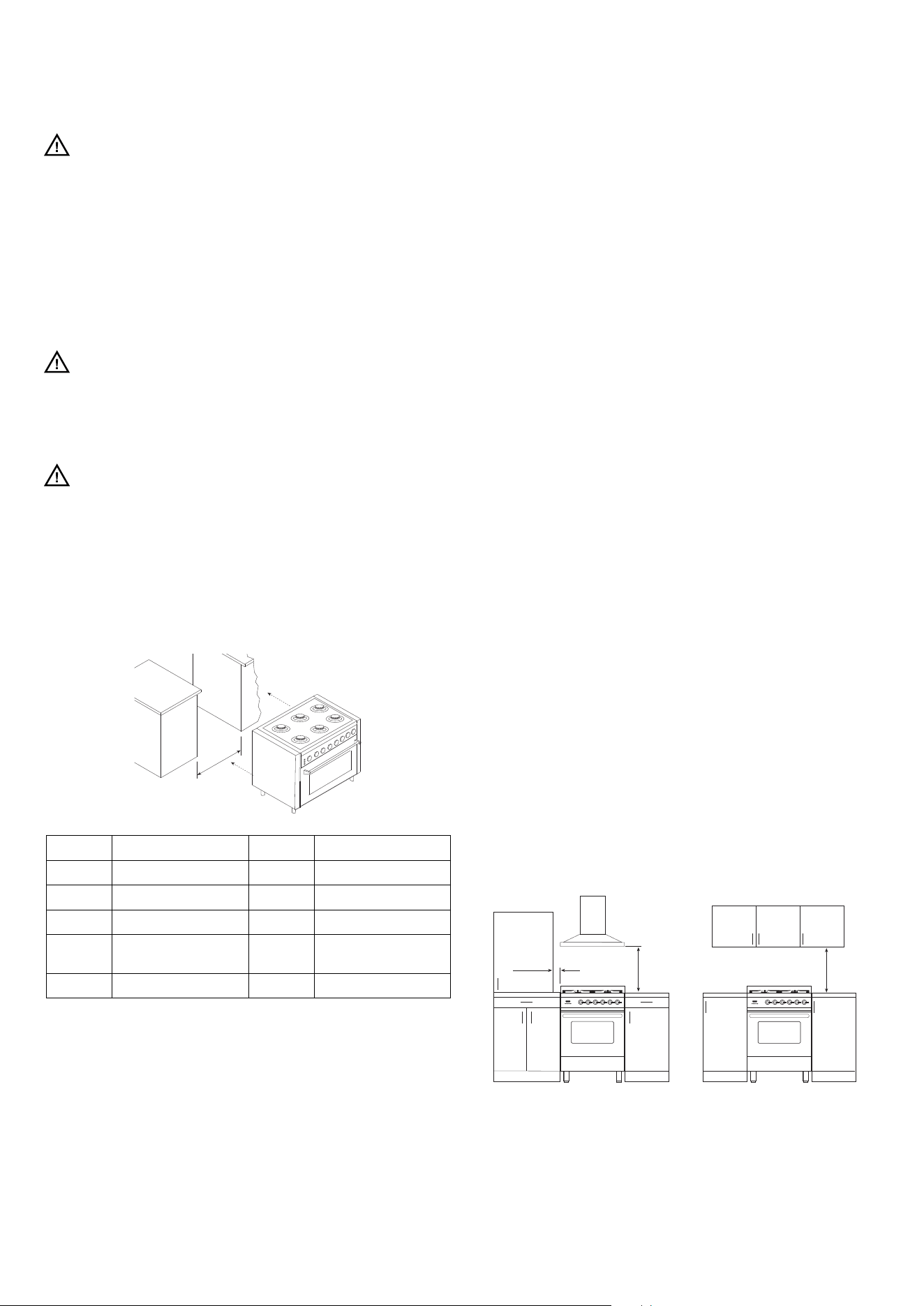
27
INSTALLATION
Instructions for installation
The installer is required to provide the user with the
following information:
-
Check the integrity of the appliance and ensure all
documentation regarding the product is present.
- Verify that the appliance has all the included accessories.
- Verify the proper use of the appliance (oven use,
thermostat use, ignition and re-ignition of burners).
- Suggest completing the warranty registration form.
- Recommend applying a periodic maintenance service at
least every two years.
Gas leak
In case of a gas leak, close the gas supply and disconnect the
appliance from the electrical network. Contact the authorized
service center. All operations and maintenance must be
carried out exclusively by authorized and qualied personnel.
Attention
The appliance weighs more than 60 kg, so handling must be
done with appropriate equipment.
Measures to be followed
To avoid bending the support feet, never drag the appliance.
The correct procedure for positioning the appliance involves
liing it using proper equipment. DO NOT LIFT BY HANDLE
a
a (mm) models a (mm) models
600 P06 - L06 1000 PD10 - M10 - LD10
700 P07 - M07 1200 P12 - L12
800 P08 1216 M12 - PM12
900
P09 - L09 - K09 -
PD09 - LD09
1500 P15
911 M09 - PM09 1511 M15
Directives / regulations
This appliance is in compliance with the applicable standards.
Installation must only be carried out by qualied persons in com-
pliance with the regulations and standards in force.
Room ventilation
This is a type “A” appliance which does not need to be joined to
an exhaust system for combustion waste but must be installed
under a hood or other smoke extraction system in compliance
with the standards in force. The knowledge and consultation
of the standards are a key factor for a qualied technician. In-
dicatively the amount of air necessary for burner combustion
is 2 m3/h for each KW of nominal power installed (see plate).
Should the appliance be subjected to intensive and prolonged
use, supplementary ventilation may be necessary; in such ca-
ses open a window or increase the extractor fan’s power.
Positioning of the appliance between
furniture
The cooker is protected against excessive overheating, so it may
be installed next to furniture with a height no higher than that of
the worktop. The wall in contact with the back of the cooker must
be made of re-resistant material. To install the cooker correctly,
take the following precautions.
*A. The clearance between the highest point of the highest burner
of the gas cooking appliance and a range hood should be no less
than 700mm for all models. For an overhead exhaust fan the mi-
nimum clearance is 750 mm.
This should be measured as 700mm from the highest point of
the highest burner to the overhead units.
**B. Where the distance from the periphery of the nearest burner
to any vertical combustible surface, or vertical combustible surface
covered with toughened glass or sheet metal, is less than 200 mm,
the surface shall be protected to a height C of not less than 150 mm
above the hob for the full dimension (width or depth) of the cooking
surface area. Where the gas cooking appliance is tted with a ‘spla-
sh back’, protection of the rear wall is not required.
C. If the cooker is installed under a wall unit, the minimum distance
between the highest point of the highest burner and the overhead
units must be 700 mm.
D. Zero clearance to bench surfaces at the same height as the
top edge of the cooker is permitted.
Majestic / Professional Plus / Nostalgie / Pro Line/ Panoramagic
Min.
650 mm
Min.
700 mm
Min.
50 mm
*
**
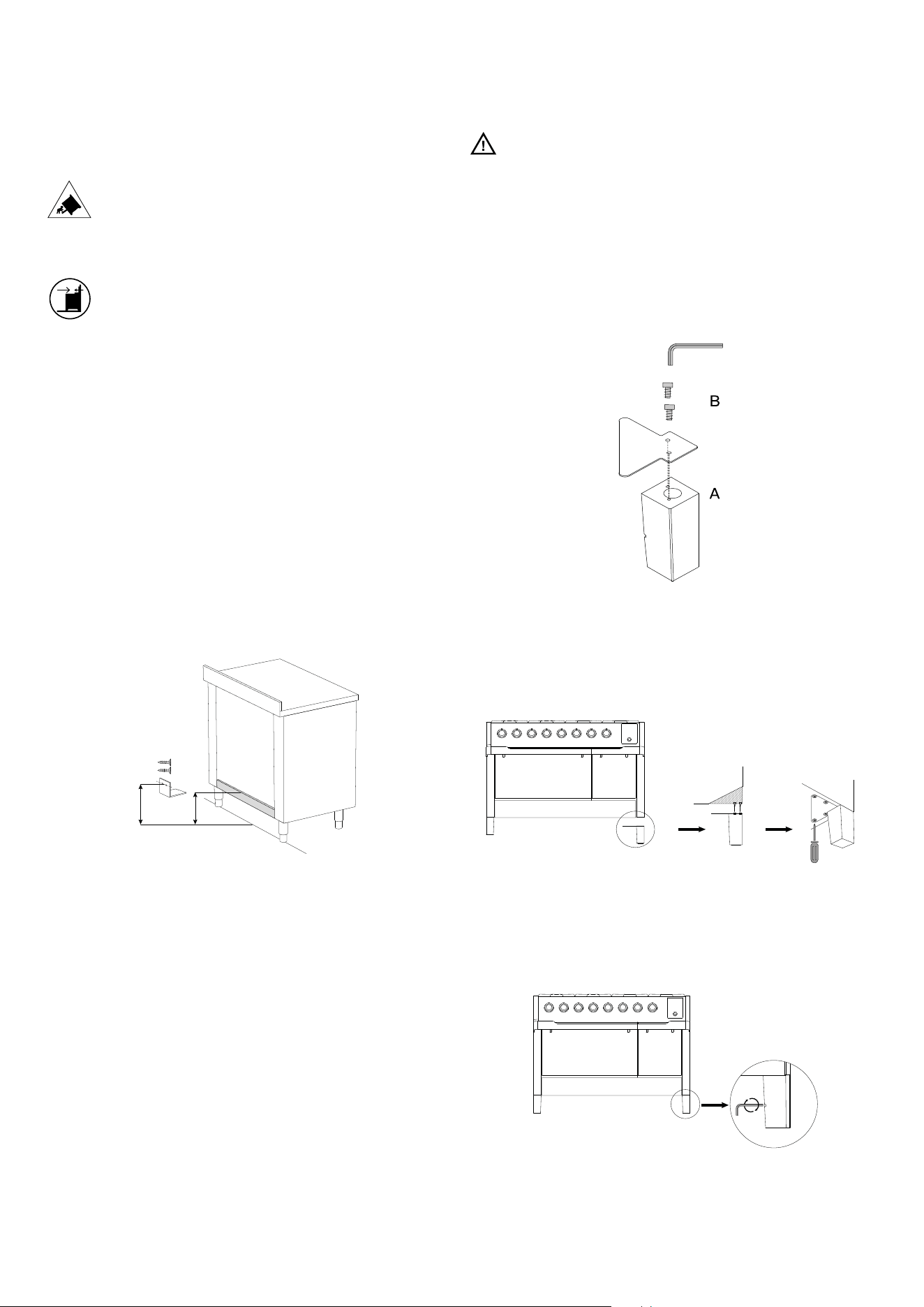
28
INSTALLATION
Instructions for installation
How to install the fixing bracket
WARNING: possibility of
overturning
WARNING: to prevent the device
from overturning, this stabilizing me-
ans must be installed. Refer to
the installation instructions.
.Modelli: 60, 70, 80 (30’), 90, 100, 120 cm.
1. Unbox the kitchen and install the feet, adjusting to the
desired height.
2. Measure the height between the oor and the top edge of
the rear crossbar and add 15 mm.
3. Mark the total measurement on the back wall of the
appliance, approximately at the center of the width of the
kitchen. Drill a hole with an appropriate drill bit of 6 mm
diameter and secure the bracket in place.
4. Ensure that the kitchen can rest against the back wall
and, when in place, it does not allow tipping.
ATTENZIONE! Il sistema anti ribaltamento è garantito
solo se la cucina è installata con la schiena appoggiata alla
parete posteriore.
Foot mounting (Panoramagic)
1. Fixing the bracket to the foot:
- Place the bracket on top of the foot base and ensure that
the holes align (a).
- Secure the 2 screws using an Allen key (b).
2. Flip the kitchen and place it on its rear side, then:
- Position the foot and ensure that the screws align with the
holes on the kitchen (a)
- Secure the screws using a screwdriver (4 screws with 4
washers) (b).
3. Adjusting the height of the feet:
- Insert the Allen key into the hole of the foot to engage the
adjustment screw (a).
- By turning the adjustment screw, the foot height can be
adjusted to eliminate any irregularities in the floor.
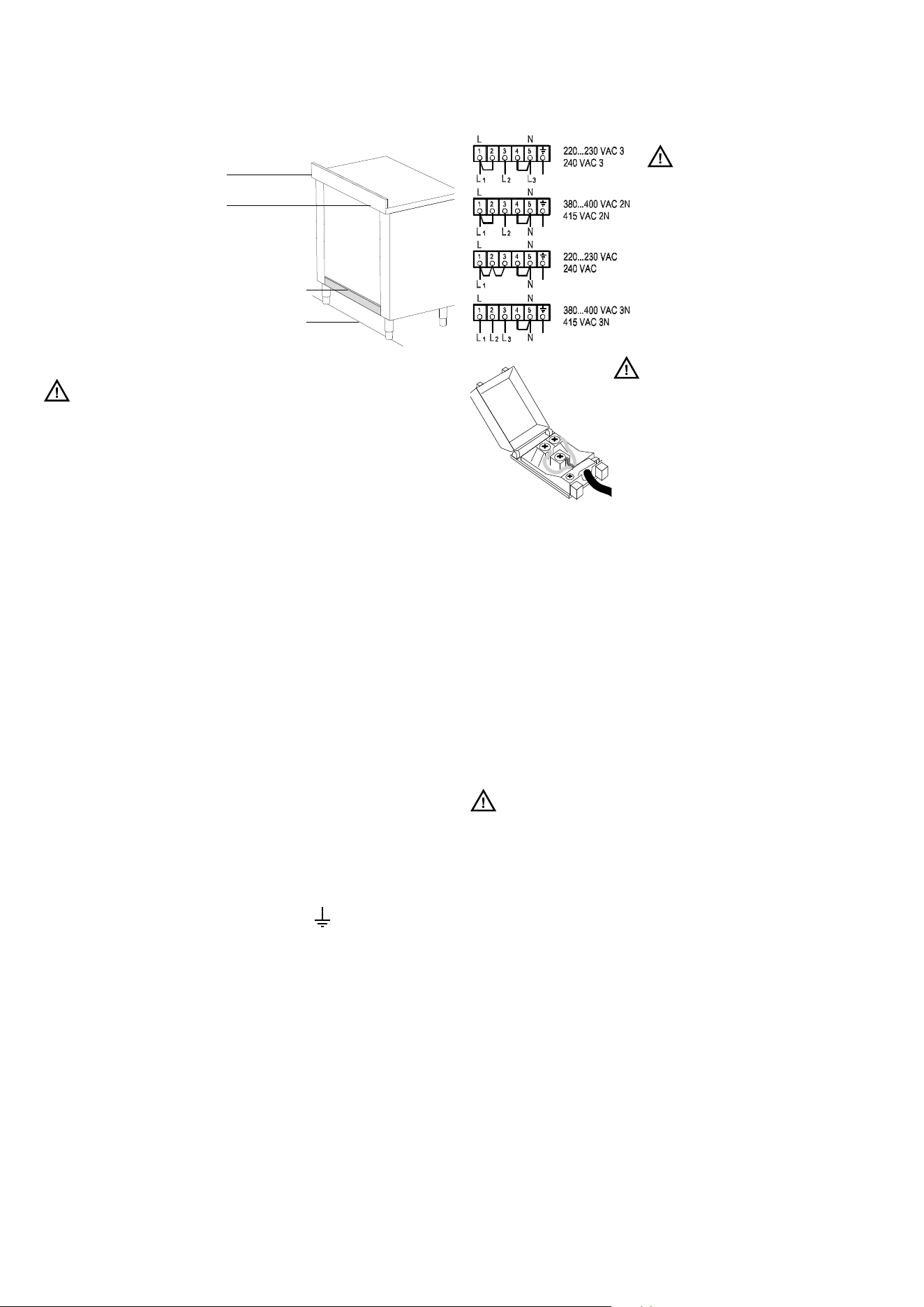
29
INSTALLATION
Electrical connection
Fix backguard
using two screws
Backguard installation
Please follow the following installation in-
structions in sequence:
- Place the backguard and fasten it with
the two screws as shown in gure.
- Please refer to a qualied installer in
case the enclosed hardware cannot
be utilized.
Range cookers
ATTENTION! The instructions below are intended for
the skilled technician who will install the cooker, regulate it and
perform technical maintenance and who will ensure that these
operations are carried out in the most correct way possible, in
compliance with the regulations in force.
Important: the cooker must be disconnected from the
electric socket before performing all regulating or mainte-
nance operations.
Rules for installation
Installation must be carried out in a workmanlike manner, ful-
ly complying with the legislation in force regarding electrical
installations. Otherwise, the manufacturer disclaims any re-
sponsibility. You will nd your appliance’s wiring diagram in this
booklet.
The appliances are prepared for connection to the voltage
shown on the data plate.
Before connecting the appliance to the mains check that:
-the electromagnetic switch or the socket are able to support
the appliance’s load (see dataplate);
-the power supply system must have an ecient grounding sy-
stem.
The appliance is supplied with a cable but without a plug: the
connection must be made taking into account that the gre-
en-yellow cable is the ground conductor
and it must never
be interrupted.
The socket must be visible and easily reachable so that the ap-
pliance can easily be disconnected. For direct connection to
the mains, it is necessary that:
-the relief valve and domestic system can support the equip-
ment’s load (see data plate)
-the power supply system must have an ecient grounding system
- a device must be provided to ensure disconnection from the
network, with a contact opening distance that allows full di-
sconnection under the conditions of overvoltage category III, in
accordance with the installation rules.
-the socket or omnipolar switch, with a minimum 3 mm con-
tact opening, must be easily reachable once the appliance has
been installed.
- means for disconnection must be incorporated in the xed
wiring in accordance with the wiring rules
ATTENTION
The range cooker can be supplied
with single-phase, two-phase or
three-phase voltage. For correct
connection to the mains, follow
the diagram below which shows
the terminal box, in particular the
connection terminals (1-2-3-4-
5) and the various power supply
lines (L1-L2-L3-N).
ATTENTION
The yellow-green ground wire must ne-
ver be interrupted even by the switch.
The power cable should be positioned
so that it does not come into contact
with surfaces that have a temperature
of 50 °C higher than the environment. In
case replacement of the power cable is
necessary, contact the support service.
If this cooking range is to be connected to a new or upgraded
electrical installation, then it must be connected to the supply
by a supply cord tted with:
– an appropriately rated plug that is compatible with the
socket-outlet tted to the nal sub-circuit in the xed wiring
that supplies this cooking range; or
– an appropriately rated installation male connector that is com-
patible with the installation female connector tted to the nal
sub-circuit in the xed wiring that supplies this cooking range.
Disconnection incorporated in the xed wiring shall be in ac-
cordance with AS/NZS 3000.
ATTENTION
The appliance is supplied without outlet: you need a normal
one proper for the electric load. The power supply cable should
not reach a 50°C temperature above the one of the surroun-
ding.
In range cookers with induction hobs, the 220...230...240 VAC3
connection must not be made.
(*) calculated by applying the coincidence factor EN60335-2-6
On kitchens whit induction hobs, the 220... 230... 240... VAC3
connection must not be made.
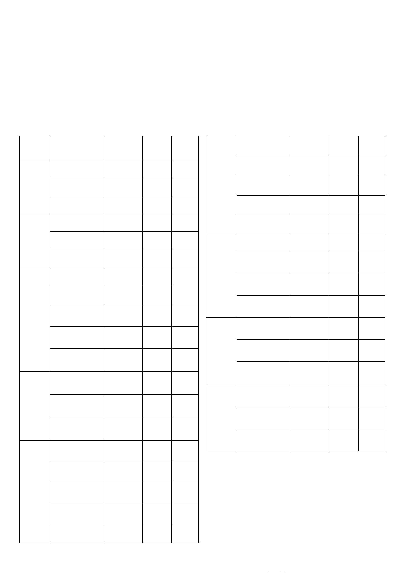
30
INSTALLATION
Electrical connection
Cooking units with induction hob
WARNING! The appliance is supplied without a cable and plug; therefore, a standardized cable and plug must be installed,
capable of handling the load (see table). The power supply cable must be positioned in such a way that at no point it reaches a
temperature higher than 50°C above the ambient temperature.
For cookers with an induction hob, the 220/230/240 VAC3 connection should not be made
Power supply cable specications (with induction top)
Mod. Power supply Connections
Cable
cross-
section
Cable
type
P..I06
LBI095
220-240V a.c. 1P+N
50/60 Hz
1 fase + N 3 x 10 H05RR
380-415V a.c. 2P+N
50/60Hz
2 fase + N 4 x 4 H05RR
380-415V a.c. 3P+N
50/60Hz
3 fase + N 5 x 1,5 H05RR
P..I09..
M..I09..
220-240V a.c. 1P+N
50/60 Hz
1 fase + N 3 x 10 H07RN
380-415V a.c. 2P+N
50/60Hz
2 fase + N
4 x 4 H05RR
380-415V a.c. 3P+N
50/60Hz
3 fase + N 5 x 4 H05RR
PDI09..
220-240V a.c. 1P+N
50/60 Hz
1 fase + N 3 x 10 H07RN
380-400V a.c. 2P+N
50/60 Hz
2 fase + N 4 x 6 H05RR
415V a.c. 2P+N
50/60 Hz
2 fase + N 4 x 10 H05RR
380-400V a.c. 3P+N
50/60 Hz
3 fase + N
5 x 6 H05RR
415V a.c. 3P+N
50/60 Hz
3 fase + N
5 x 10 H05RR
LDBI09..
220-240V a.c. 1P+N
50/60 Hz
1 fase + N 3 x 6 H05RR
380-415V a.c. 2P+N
50/60 Hz
2 fase + N 4 x 4 H05RR
380-415V a.c. 3P+N
50/60 Hz
3 fase + N
5 x 2,5 H05RR
MDI10..
E3
220-240V a.c. 1P+N
50/60 Hz
1 fase + N 3 x 10 H07RN
380-400V a.c. 2P+N
50/60 Hz
2 fase + N 4 x 6 H05RR
415V a.c. 2P+N
50/60 Hz
2 fase + N 4 x 10 H05RR
380-400V a.c. 3P+N
50/60 Hz
3 fase + N 5 x 6 H05RR
415V a.c. 3P+N
50/60 Hz
3 fase + N 5 x 10 H05RR
PDI10..
220-240V a.c. 1P+N
50/60 Hz
1 fase + N 3 x 10 H07RN
380V a.c. 2P+N
50/60 Hz
2 fase + N 4 x 6 H05RR
400-415V a.c. 2P+N
50/60 Hz
2 fase + N 4 x 10 H05RR
380V a.c. 3P+N
50/60 Hz
3 fase + N
5 x 6 H05RR
400-415V a.c. 3P+N
50/60 Hz
3 fase + N
5 x 10 H05RR
PI127..
MI127..
220-240V a.c. 1P+N
50/60 Hz
1 fase + N 3 x 10 H07RN
380-415V a.c. 2P+N
50/60 Hz
2 fase + N 4 x 10 H05RR
380V a.c. 3P+N
50/60 Hz
3 fase + N
5 x 6 H05RR
400-415V a.c. 3P+N
50/60 Hz
3 fase + N
5 x 10 H05RR
PMI09S3
220-240V a.c. 1P+N
50/60 Hz
1 fase + N 3 x 10 H07RN
380-415V a.c. 2P+N
50/60 Hz
2 fase + N 4 x 6 H05RR
380-415V a.c. 3P+N
50/60 Hz
3 fase + N
5 x 4 H05RR
PMI127S3
220-240V a.c. 1P+N
50/60 Hz
1 fase + N 3 x 10 H07RN
380-415V a.c. 2P+N
50/60 Hz
2 fase + N 4 x 10 H05RR
380-415V a.c. 3P+N
50/60 Hz
3 fase + N
5 x 4 H05RR
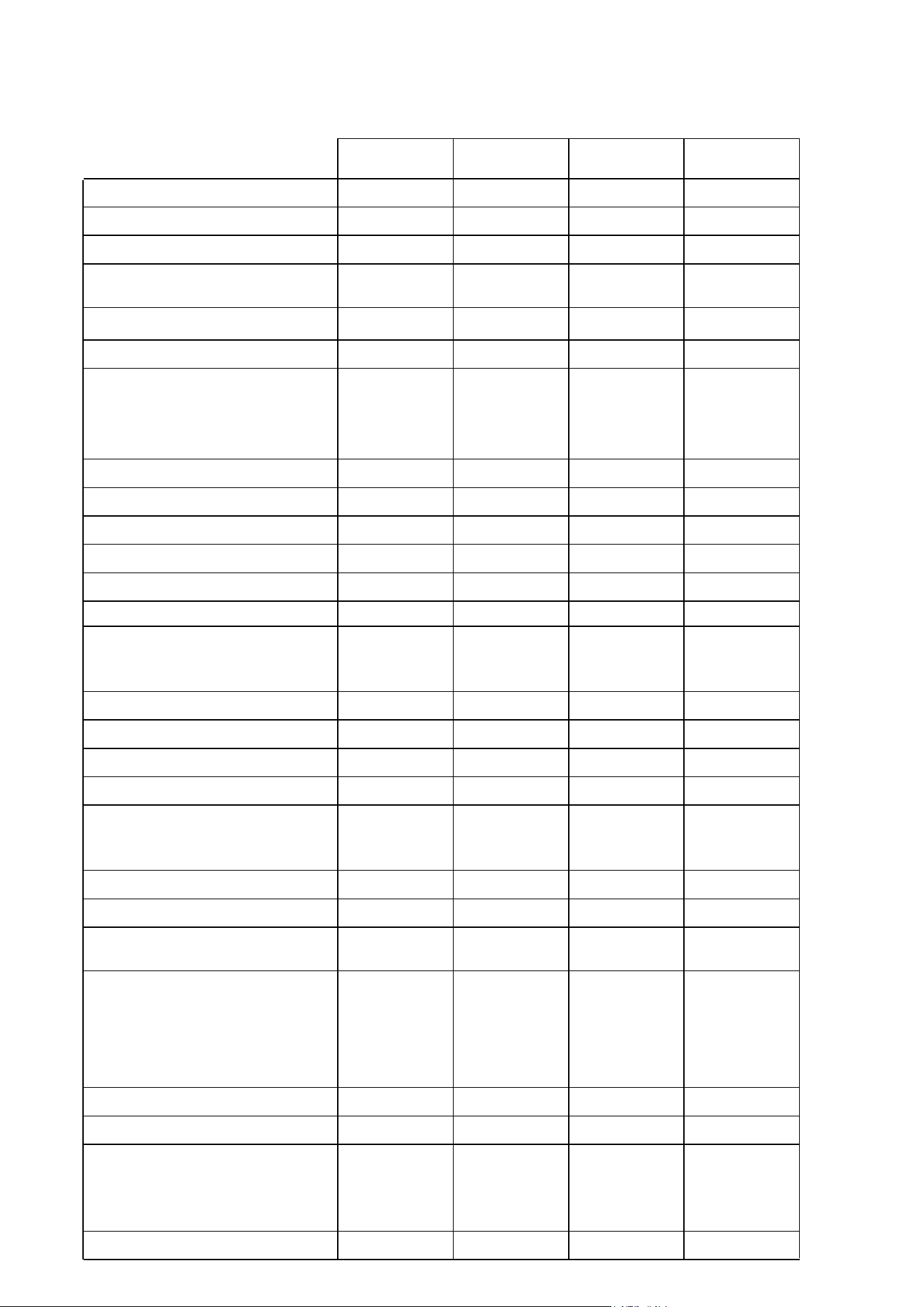
31
INSTALLATION
Electrical connection (with gas top)
240 a.c.
1P+N+T
50Hz
240 a.c.
3P+T
50Hz
415 a.c.
2P+N+T
50Hz
415 a.c.
3P+N+T
50Hz
L06(W/F/L/N/S)(MP/M3)
3 x 1,5 mm
2
H05RR-F
P06(F/L/W/N/S)E3 - N06(W/Q/N/QN)E3
P06(F/L/W/N/S)DE3 - N06(W/Q/N/QN)DE3
3 x 1,5 mm
2
H05RR-F
P07(F/L/W/N/S)E3 - N07(W/Q/N/QN)E3
P07(F/L/W/N/S)DE3 - N07(W/Q/N/QN)DE3
3 x 1,5 mm
2
H05RR-F
P08(P)(F/L/W/N/S)E3 - N08(P)(W/Q/N/QN)E3
P08(C)(F/L/W/N/S)E3 - N08(C)(W/Q/N/QN)E3
P08(PD)(F/L/W/N/S)E3 - N08(PD)(W/Q/N/QN)E3
P08(D)(F/L/W/N/S)E3 - N08(D)(W/Q/N/QN)E3
3 x 1,5 mm
2
H05RR-F
V09(6/C)SV - V09(6/C)V
V09(6/C)SVP - V09(6/C)VP
V09(6/C)SMP - V09(6/C)MP
3 x 1,5 mm
2
H05RR-F
L09(6)(W/F/L/N/S)(MP/M3) - L09(F)(W/F/L/N/S)(MP/M3)
L09(C)(W/F/L/N/S)(MP/M3)
3 x 1,5 mm
2
H05RR-F
P09(P)(F/L/W/N/S)E3 - N09(P)(W/Q/N/QN)E3
P09(6)(F/L/W/N/S)E3 - N09(6)(W/Q/N/QN)E3
P09(F)(F/L/W/N/S)E3 - N09(F)(W/Q/N/QN)E3
P09(PD)(F/L/W/N/S)E3 - N09(PD)(W/Q/N/QN)E3
P09(6D)(F/L/W/N/S)E3 - N09(6D)(W/Q/N/QN)E3
P09(FD)(F/L/W/N/S)E3 - N09(FD)(W/Q/N/QN)E3
P09(6DD/FDD)(L/W)MP - P09(6DD/FDD)(L/W)M3
3 x 1,5 mm
2
H05RR-F
P09(I)(F/L/W/N/S)E3 - N09(I)(W/Q/N/QN)E3
P09(ID)(F/L/W/N/S)E3 - N09(ID)(W/Q/N/QN)E3
3 x 4 mm
2
H05RR-F
4 x 1,5 mm
2
H05RR-F
4 x 1,5 mm
2
H05RR-F
M07D(N/W/Q/QN)E3
3 x 1,5 mm
2
H05RR-F
M30D(N/W/Q/QN)E3
3 x 1,5 mm
2
H05RR-F
M09(PD)(N/W/Q/QN)E3 - M09(6D)(N/W/Q/QN)E3
M09(FD)(N/W/Q/QN)E3
3 x 1,5 mm
2
H05RR-F
M09(ID)(N/W/Q/QN)E3
3 x 4 mm
2
H05RR-F
4 x 1,5 mm
2
H05RR-F
4 x 1,5 mm
2
H05RR-F
LD09(6)(W/F/L/N/S)(MP/M3) - LD09(C)(W/F/L/N/S)(MP/M3)
LD09(F)(W/F/L/N/S)(MP/M3)
3 x 2,5 mm
2
H05RR-F
4 x 1,5 mm
2
H05RR-F
4 x 1,5 mm
2
H05RR-F
PD09(P)(F/L/W/N/S)(E3) - ND09(P)(W/Q/N/QN)(E3)
PD09(6)(F/L/W/N/S)(E3) - ND09(6)(W/Q/N/QN)(E3)
PD09(F)(F/L/W/N/S)(E3) - ND09(F)(W/Q/N/QN)(E3)
PD09(PD)(F/L/W/N/S)(E3) - ND09(PD)(W/Q/N/QN)(E3)
PD09(6D)(F/L/W/N/S)(E3) - ND09(6D)(W/Q/N/QN)(E3)
PD09(FD)(F/L/W/N/S)(E3) - ND09(FD)(W/Q/N/QN)(E3)
3 x 2,5 mm
2
H05RR-F
4 x 1,5 mm
2
H05RR-F
4 x 1,5 mm
2
H05RR-F
PD09(I)(F/L/W/N/S)(E3) - ND09(I)(W/Q/N/QN)(E3)
PD09(ID)(F/L/W/N/S)(E3) - ND09(ID)(W/Q/N/QN)(E3)
3 x 10 mm
2
H07RN-F
4 x 2,5 mm
2
H05RR-F
4 x 2,5 mm
2
H05RR-F
5 x 1,5 mm
2
H05RR-F
LD10(6)(W/F/L/N/S)(MP/M3) - LD10(C)(W/F/L/N/S)(MP/M3)
LD10(F)(W/F/L/N/S)(MP/M3)
3 x 2,5 mm
2
H05RR-F
4 x 1,5 mm
2
H05RR-F
4 x 1,5 mm
2
H05RR-F
MD10(6D)(N/W/Q/QN)(E3) - MD10(FD)(N/W/Q/QN)(E3)
MD10(SD)(N/W/Q/QN)(E3)
3 x 2,5 mm
2
H05RR-F
4 x 1,5 mm
2
H05RR-F
4 x 1,5 mm
2
H05RR-F
MD10(ID)(N/W/Q/QN)(E3)
3 x 10 mm
2
H07RN-F
4 x 2,5 mm
2
H05RR-F
4 x 2,5 mm
2
H05RR-F
5 x 1,5 mm
2
H05RR-F
PD10(6)(F/L/W/N/S)(E3) - ND10(6)(W/Q/N/QN)(E3)
PD10(F)(F/L/W/N/S)(E3) - ND10(F)(W/Q/N/QN)(E3)
PD10(S)(F/L/W/N/S)(E3) - ND10(S)(W/Q/N/QN)(E3)
PD10(6D)(F/L/W/N/S)(E3) - ND10(6D)(W/Q/N/QN)(E3)
PD10(FD)(F/L/W/N/S)(E3) - ND10(FD)(W/Q/N/QN)(E3)
PD10(SD)(F/L/W/N/S)(E3) - ND10(SD)(W/Q/N/QN)(E3)
3 x 4 mm
2
H05RR-F
4 x 1,5 mm
2
H05RR-F
4 x 1,5 mm
2
H05RR-F
PD10(I)(F/L/W/N/S)(E3) - ND10(I)(W/Q/N/QN)(E3)
PD10(ID)(F/L/W/N/S)(E3) - ND10(ID)(W/Q/N/QN)(E3)
3 x 10 mm
2
H07RN-F
4 x 4 mm
2
H05RR-F
4 x 4 mm
2
H05RR-F
5 x 1,5 mm
2
H05RR-F
L12(F)(W/F/L/N/S)(MP/M3) - L12(8)(W/F/L/N/S)(MP/M3)
3 x 2,5 mm
2
H05RR-F
4 x 1,5 mm
2
H05RR-F
4 x 1,5 mm
2
H05RR-F
P12(FI)(F/L/W/N/S)(E3) - N12(FI)(W/Q/N/QN)(E3)
P12(I)(F/L/W/N/S)(E3) - N12(I)(W/Q/N/QN)(E3)
P12(FID)(F/L/W/N/S)(E3) - N12(FID)(W/Q/N/QN)(E3)
P12(ID)(F/L/W/N/S)(E3) - N12(ID)(W/Q/N/QN)(E3)
3 x 10 mm
2
H07RN-F
4 x 4 mm
2
H05RR-F
4 x 4 mm
2
H05RR-F
5 x 1,5 mm
2
H05RR-F
P12(7)(F/L/W/N/S)(E3) - N12(7)(W/Q/N/QN)(E3)
P12(F)(F/L/W/N/S)(E3) - N12(F)(W/Q/N/QN)(E3)
P12(8)(F/L/W/N/S)(E3) - N12(8)(W/Q/N/QN)(E3)
P12(S)(F/L/W/N/S)(E3) - N12(S)(W/Q/N/QN)(E3)
P12(7D)(F/L/W/N/S)(E3) - N12(7D)(W/Q/N/QN)(E3)
P12(FD)(F/L/W/N/S)(E3) - N12(FD)(W/Q/N/QN)(E3)
P12(8D)(F/L/W/N/S)(E3) - N12(8D)(W/Q/N/QN)(E3)
P12(SD)(F/L/W/N/S)(E3) - N12(SD)(W/Q/N/QN)(E3)
P12(8DD/FDD)(L/W)MP - P12(8DD/FDD)(L/W)M3
3 x 4 mm
2
H05RR-F
4 x 1,5 mm
2
H05RR-F
4 x 1,5 mm
2
H05RR-F
M12(7D)(N/W/Q/QN)(E3) - M12(FD)(N/W/Q/QN)(E3)
M12(8D)(N/W/Q/QN)(E3) - M12(SD)(N/W/Q/QN)(E3)
3 x 4 mm
2
H05RR-F
4 x 1,5 mm
2
H05RR-F
4 x 1,5 mm
2
H05RR-F
M12(FID)(N/W/Q/QN)(E3) - M12(ID)(N/W/Q/QN)(E3)
3 x 10 mm
2
H07RN-F
4 x 4 mm
2
H05RR-F
4 x 4 mm
2
H05RR-F
5 x 1,5 mm
2
H05RR-F
P15(F)(F/L/W/N/S)(E3) - N15(F)(W/Q/N/QN)(E3)
P15(FS)(F/L/W/N/S)(E3) - N15(FS)(W/Q/N/QN)(E3)
P15(S)(F/L/W/N/S)(E3) - N15(S)(W/Q/N/QN)(E3)
P15(9)(F/L/W/N/S)(E3) - N15(9D)(W/Q/N/QN)(E3)
P15(FD)(F/L/W/N/S)(E3) - N15(FD)(W/Q/N/QN)(E3)
P15(FSD)(F/L/W/N/S)(E3) - N15(FSD)(W/Q/N/QN)(E3)
P15(SD)(F/L/W/N/S)(E3) - N15(SD)(W/Q/N/QN)(E3)
P15(9D)(F/L/W/N/S)(E3) - N15(9D)(W/Q/N/QN)(E3)
3 x 4 mm
2
H05RR-F
4 x 1,5 mm
2
H05RR-F
4 x 1,5 mm
2
H05RR-F
M15(FD)(N/W/Q/QN)(E3) - M15(FSD)(N/W/Q/QN)(E3)
M15(SD)(N/W/Q/QN)(E3) - M15(9D)(N/W/Q/QN)(E3)
3 x 4 mm
2
H05RR-F
4 x 1,5 mm
2
H05RR-F
4 x 1,5 mm
2
H05RR-F
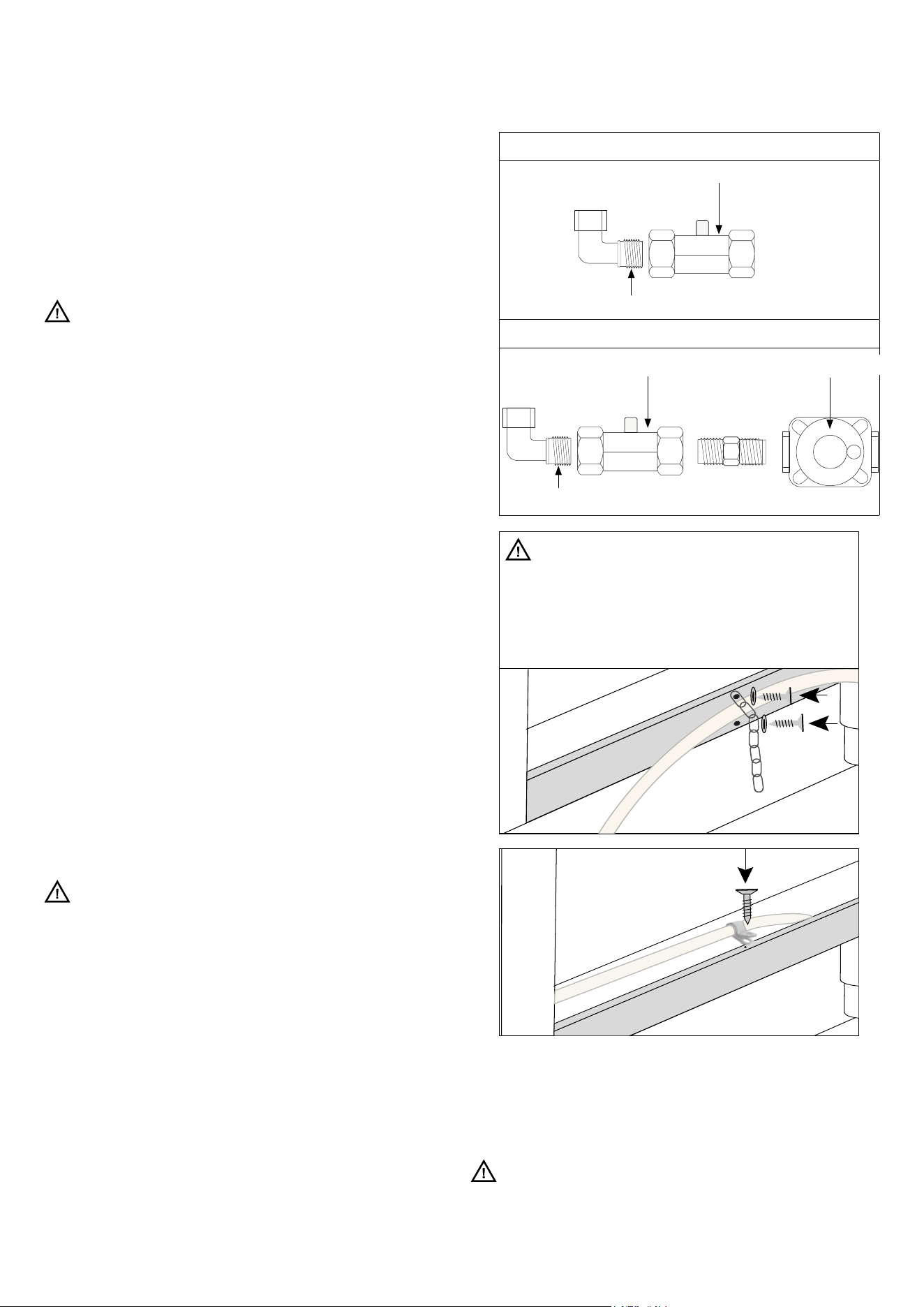
32
INSTALLATION
Gas connection
This appliance must be installed by an authorised person in
accordance with this instruction manual, AS/NZS 5601 Gas
installations (installation and pipe sizing), local gas tting
regulations, local electrical regulations, local water regulations,
local health regulations, Building Code of Australia and any other
government authority.
This appliance is suitable for connection with rigid pipe. The isolating
manual shut-o valve connection point must be accessible when
the appliance is installed.
ATTENTION! THIS APPLIANCE IS NOT SUITABLE FOR
CONNECTION WITH A HOSE ASSEMBLY
Natural Gas: the supplied regulator must be tted to the appliance
inlet connection. Gas pressure must be adjusted to 1.0 kPa when
approximately 50% of the burners are on high ame.
ULPG: the supplied test point adaptor must be tted to the
appliance inlet connection. Gas pressure must be adjusted to 2.75
kPa.
Gas leakage and operation of the appliance must be tested by the
installer before leaving. Check burner ames are blue in colour,
stable and completely ignite at both high and low ame settings with
no appreciable yellow tipping, carbon deposition, liing, oating,
lighting back or objectionable odour. Test burners individually and
in combination, When satised with the operation of the cooker,
please instruct the user on the correct method of operation.
Where the data plate is obscured by cabinetry when the cooker is
in the installed position, place the supplied duplicate data plate to a
suitable adjacent surface or within the instruction manual for future
reference.
Removing Legs and placing oven on a plinth
If the legs are removed and the oven is placed on a plinth,
then suitable ventilation from the plinth area is required. It is
recommended that an air vent 20 mm wide and a length of 100mm
less than the width of the oven it is be located at the rear in the
base of the plinth. If the area under the plinth is sealed it is also
recommended that an additional vent be included at the top of kick
panel under the plinth to provide adequate circulation. The vent
size should be 10mm high and 100mm less than the width of the
oven.
ATTENTION! Any maintenance operation, etc. It must be
carried out by an authorized technician aer disconnecting the
appliance from the mains and closing the gas supply.
Location of inlet connection point for hose assemblies
- 450 mm to 550 mm from the oor and 200 mm to 300 mm
from the le-hand side of the appliance as viewed from the
front;
- the hose connection on the appliance shall face downwards;
- an anchor point shall be provided on the appliance so that a
restraining device can be tted to restrict the appliance
movement to no more than 80 % of the hose length; )
Lpg gas connection
1/2” BSP (male)
Test point pressure
Natural gas connection
Test point pressure
Gas regulator
1/2” BSP (male)
ATTENTION! THIS APPLIANCE IS NOT SUITABLE
FOR CONNECTION WITH A HOSE ASSEMBLY
Fitting the restraining chain for gas connection
The restraining chain MUST be tted like these
pictures.
It is recommended to connect the tightness
of the connections with special foaming (NO FLAME).
Transformation for Other Gases
The appliance is delivered to operate as indicated on the label
on the appliance. If a transformation with other gases is
necessary, proceed as described in the paragraph “adjustment
and/or adaptation to dierent types of gases”
ATTENTION
Any maintenance operation, etc. It must be carried out by an
authorized technician aer disconnecting the appliance from
the mains and closing the gas supply.
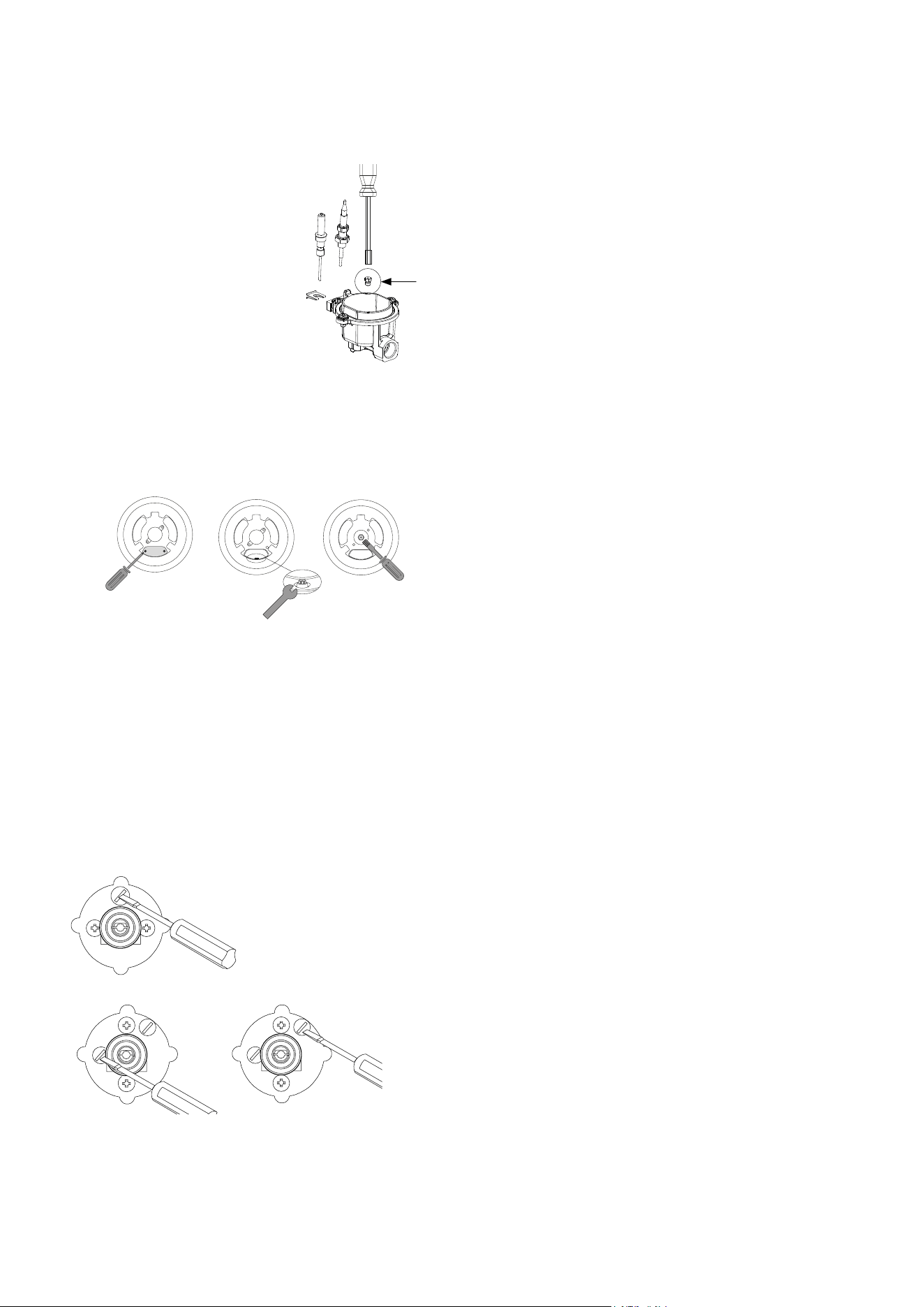
33
INSTALLATION
Adjustment
Adjustment and/or adaptation to dierent types
of gas
U
SR - R - P
1. Remove the grid and burners
from the hob.
2. SR – R – P Burners: Unscrew
the “U” injectors using a 7 mm
wrench and replace them with
those intended for the new gas,
according to the table below.
DCC/DUAL
1. DCC/DUAL Burners: Unscrew the two screws and remove the
cover.
2. Unscrew the “U” injectors using a 7 mm wrench and replace
them with those intended for the new gas according to tables
No. 1 and No. 2.
Minimum Adjustment
Control adjustment
When installing the appliance, it is necessary to check that the
minimum setting of the burners on the hob and in the oven is
correctly adjusted. If the type of gas is changed, the minimum
adjustment is essential. The adjustment is carried out as follows.
Hob burners
1. Turn on one burner at a time and set the ame to maximum.
2. Remove the corresponding gas valve knob and insert a
screwdriver either into the valve’s nal part or into the screw.
DUAL
3. Set the valve to the minimum position.
4. Unscrew by turning le to increase the ame, or screw in to
the right to decrease it.
5. If using liqueed gas (Butane - Propane), the adjustment
screw should be fully screwed in.
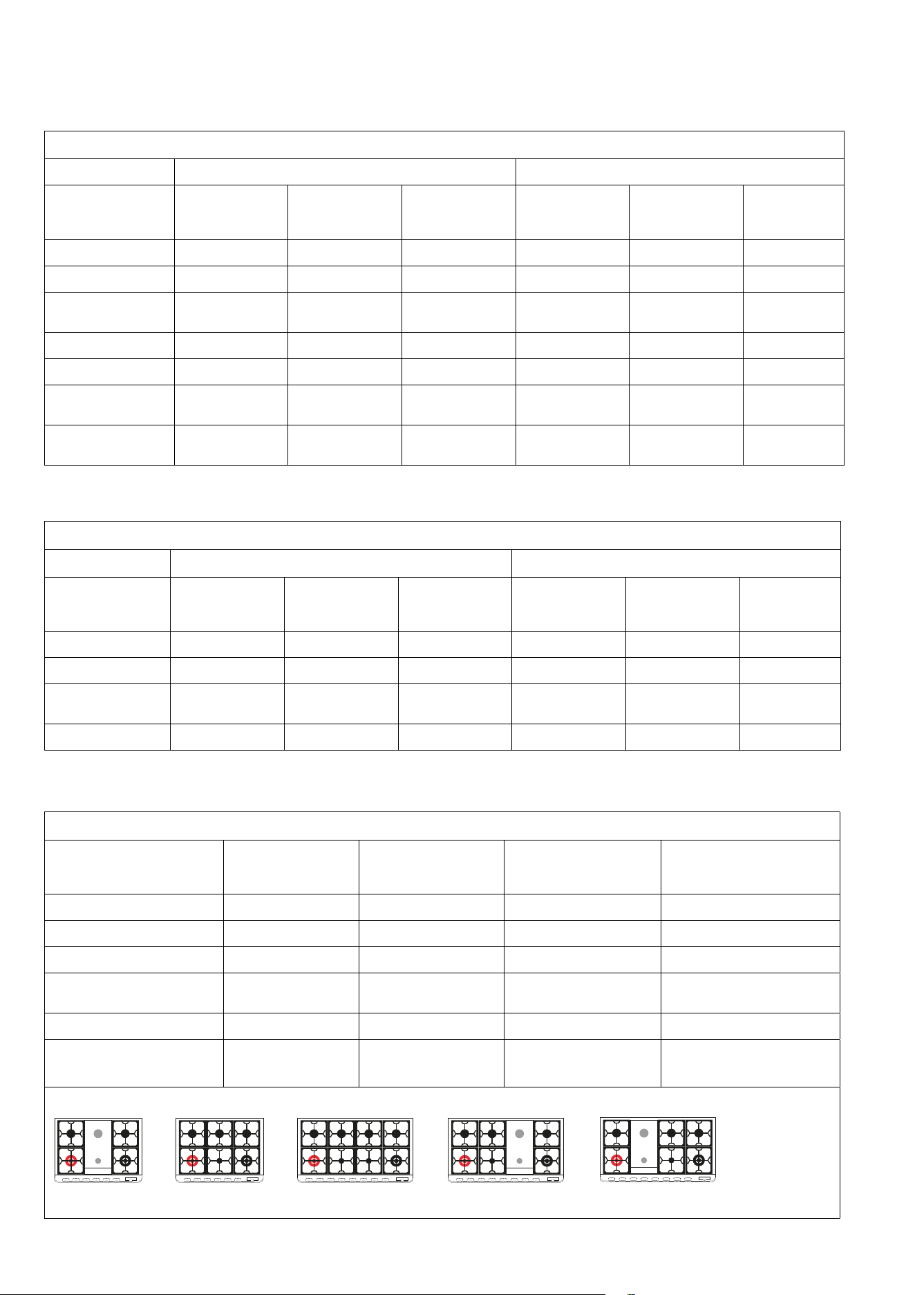
34
ADJUSTMENT
Burner chart
PROLINE
NATURAL GAS ULPG
Burner Injector Size
(mm)
Nominal Gas
Consumption
(MJ/h)
Pressure
(kPa)
Injector Size
(mm)
Nominal Gas
Consumption
(MJ/h)
Pressure
(kPa)
DCC wok 2.00 18.0 1.00 1.15 18.0 2.75
LARGE - R 1.55 12.0 1.00 0.95 12.0 2.75
LARGE - R
under fry-top
1.40 10.0 1.0 0.85 10.0 2.75
MEDIUM - SR 1.25 7.5 1.00 0.74 7.0 2.75
PANORAMAGIC
Burner Injector Size (mm) NG consumption
@ 1kPa (MJ/h)
Injector Size (mm) NG consumption
@ 2.75kPa (MJ/h))
DUAL wok 1.75 / 0.80 17.0 1.10 /0.50 20.0
Wok DCC 1.95 17.0 1.15 18.0
LARGE - R 1.55 12.0 0.95 12.0
LARGE - R1
under fry-top
1.40 10.0 0.85 10.0
MEDIUM - SR 1.25 7.5 0.74 7.0
Tepanyaki Plate
(medium and large burner)
1.25, 1.40 7.5 + 10 0.85, 0.74 7.0 + 10
R RR1
DUAL DCCSR SRSR
R RR
DUAL DCCSR
R R R R
DUAL DCCSR SR
R R R1 R
DUAL DCCSR
R R1 R R
DUAL DCCSR
PROFESSIONAL / MAJESTIC
NATURAL GAS ULPG
Burner Injector Size
(mm)
Nominal Gas
Consumption
(MJ/h)
Pressure
(kPa)
Injector Size
(mm)
Nominal Gas
Consumption
(MJ/h)
Pressure
(kPa)
DCC wok 2.00 18.00 1.00 1.15 18.0 2.75
LARGE - R 1.55 12.00 1.00 0.95 12.0 2.75
LARGE - R
under fry-top
1.40 10.00 1.0 0.85 10.0 2.75
MEDIUM - SR 1.25 7.5 1.00 0.74 7.0 2.75
FISH - P 1.55 12.5 1.00 0.95 13 2.75
SIMMER PLATE -
C.d.F.
1.40 10.0 1.00 0.83 9.0 2.75
DUAL WOK 0.80
1.75
Inner: 3.3
Total: 17.0
1.00 0.50
1.10
Inner: 3.3
Total: 20.0
2.75
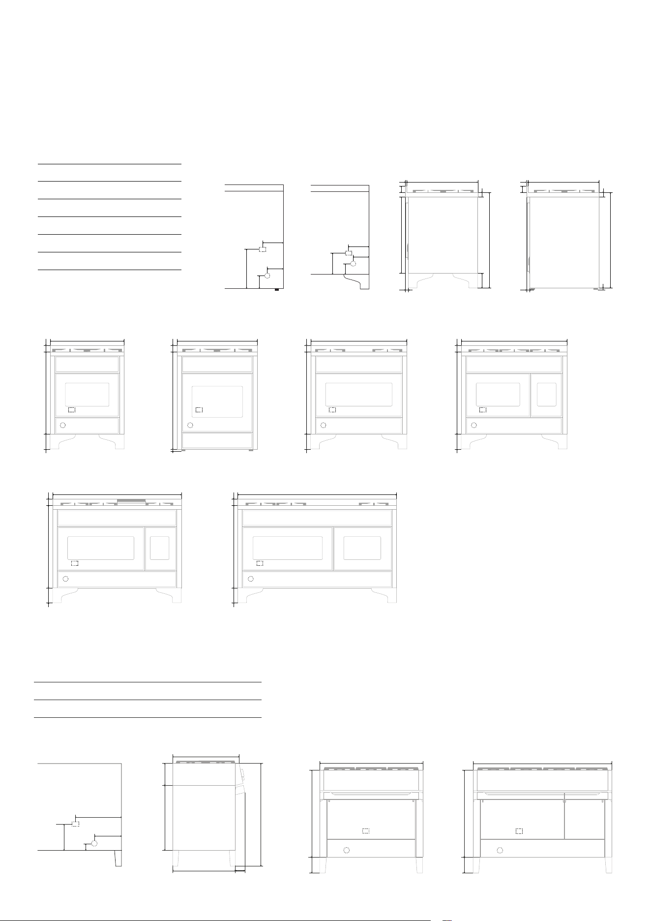
35
E = Electrical connection
G = Gas connection
INSTALLATION
Electrical connections and installation diagrams
365
115
A
B
E
G
245
110
A
B
E
G
60743
40 144
927
30
15
685
60
40
890
30
37
15
685
783 60
144
1216
E
G
783 60144
1511
E
G
Majestic
Mod. /mm A B
M07 185 155
M30 120 90
M09 190 165
MD10 140 120
M12 150 120
M15 195 170
M07
M12 M15
M09M30 MD10
Rear view
Rear view
– M30
Side view M30
Panoramagic
E
G
205
14
A
B
Mod. /mm A B
PM09 455 183
PM12 457 192
PM09 PM12
Rear view
Side view
97
910
198
571
687
650 97
E
G
911
769141
1216
769141
E
G
Side view
890 60
760
37
E
G
783 60144
700
E
G
783 60
144
911
E
G
783 60
144
1000
E
G
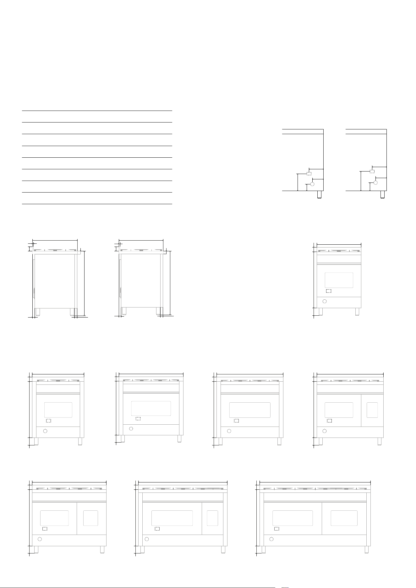
36
INSTALLATION
Electrical connections and installation diagrams
E
G
760 60
1200
100
÷160
15
60
35 55
600
40
860÷920
60
860÷920
87
60
40
650
15
E
G
760 60
1500
100
÷160
E
G
700
760 60
100
÷160
E
G
760 60
600
100
÷160
E
G
760 60
900
100
÷160
E
G
760 60
911
100
÷160
E
G
760 60
900
100
÷160
E
G
100
÷160 760 60
1000
E
G
230
90
A
B
E
G
260
110
A
B
Nostalgie, Professional Plus, Pro Line
P06N / P06W / L06
P12N / P12W / L12 P15N / P15W
P09N / P09W / L09 P36N / P36W PD09N / PD09W / LD09P07N / P07W
PD10N / PD10W / LD10
Mod. /mm A B
P06N / P06W / L06 130 80
P07N / P07W 190 150
P09N / P09W / L09 240 150
PD09N / PD09W / LD09 140 80
PD10N / PD10W / LD10 140 80
P12N / P12W / L12 225 90
P15N / P15W 200 135
P36N / P36W 200 150
Rear view Rear view
P36N / P36W
Side view
P36N / P36W
Side view
E = Electrical connection
G = Gas connection
37
INSTALLATION
Key
00 Black
11 Brown
22 Red
33 White
44 Yellow
45 Yellow-green
55 Grey
66 Blue
AA Electrical ignition transformer
C Commutator
CA Capacitor 1,05 µF
CCDF Fry-Top switch
CP Cooking probe
DM Dumper microonde
DV Dumper vapore
DS1 Burner control
DU Wax thermal actuator discharging steam
DY Display
EL Solenoid valve
EN Encoder
F Phase
F1 Phase 1
FLC LC Filter
FUSE Fuse 10A
HVD High voltage diode
K1 Earth wire terminal block
K2 Earth wire lower resistance
K3 Earth wire oven fan
K4 Earth wire circulating resistance
K5 Earth wire upper resistance
K6 Earth wire oven light 1
K7 Earth wire oven light 2
K8 Earth wire roaster
K9 Earth wire cooling fan.
K10 Earth wire commutator
K11 Earth wire oven thermostat
K12 Earth wire programmer/timer
K13 Earth wire grill resistance
K14 Earth wire piastra elettrica
K15 Earth wire frame
K16 Earth wire barbecue resistance
K17 Earth wire resistenza friggitrice
L1
Oven light
L2 Oven light
M Terminal block
MA Electrical ignition microswitch
MD Grill microswitch
MG Rotisserie
MGT Magnetron
MP Door microswitch
MMO Monitor microswitch for microwave
MPR Primary microswitch for microwave
MSEC Secondary microswitch for microwave
MT Micro cooling fan
MTK Water loading tank microswitch
MVT Cooling fan microswitch
N Neutral
NTC Temperature probe
P Timer\Clock - Timer\Programmer
PB Power board
PD Pump
PE Electric hotplate
PT1000 Temperature probe
R1 Upper resistance
R2 Lower resistance
R3 Grill resistance
R4 Circulating resistance
R5 Barbecue resistance
R6 Fryer resistance
RC Boiler heating element
RE Energy controller
RL Limit resistance
S1 Oven warning light
S2 Mains power warning light
S3 Grill warning light
S4 Cooling fan warning
S5 Barbecue warning light
S6 Electric hotplate warning light
S7 Rotisserie warning light
S8 Residual heat warning light
S9 Fryer warning light
SA Power supply board
SD Display board
SE Auxiliary power board
SI Interface board
SL Water level detector
SP Power board
SPI Candela di accensione
SR Safety Relay
SWD Warming drawer control board
T Grill thermostat
TCO\TC1 Safety thermostat 318 °C (TCO)
TSPO Safety thermostat 90 °C
TF Oven thermostat
TR Fryer thermostat\ High voltage transformer
TS\TS1\
TS2
Safety thermostat
TST Tangential motor safety thermostat
TT Tangential thermostat
V\VR Oven fan
VT Cooler fan
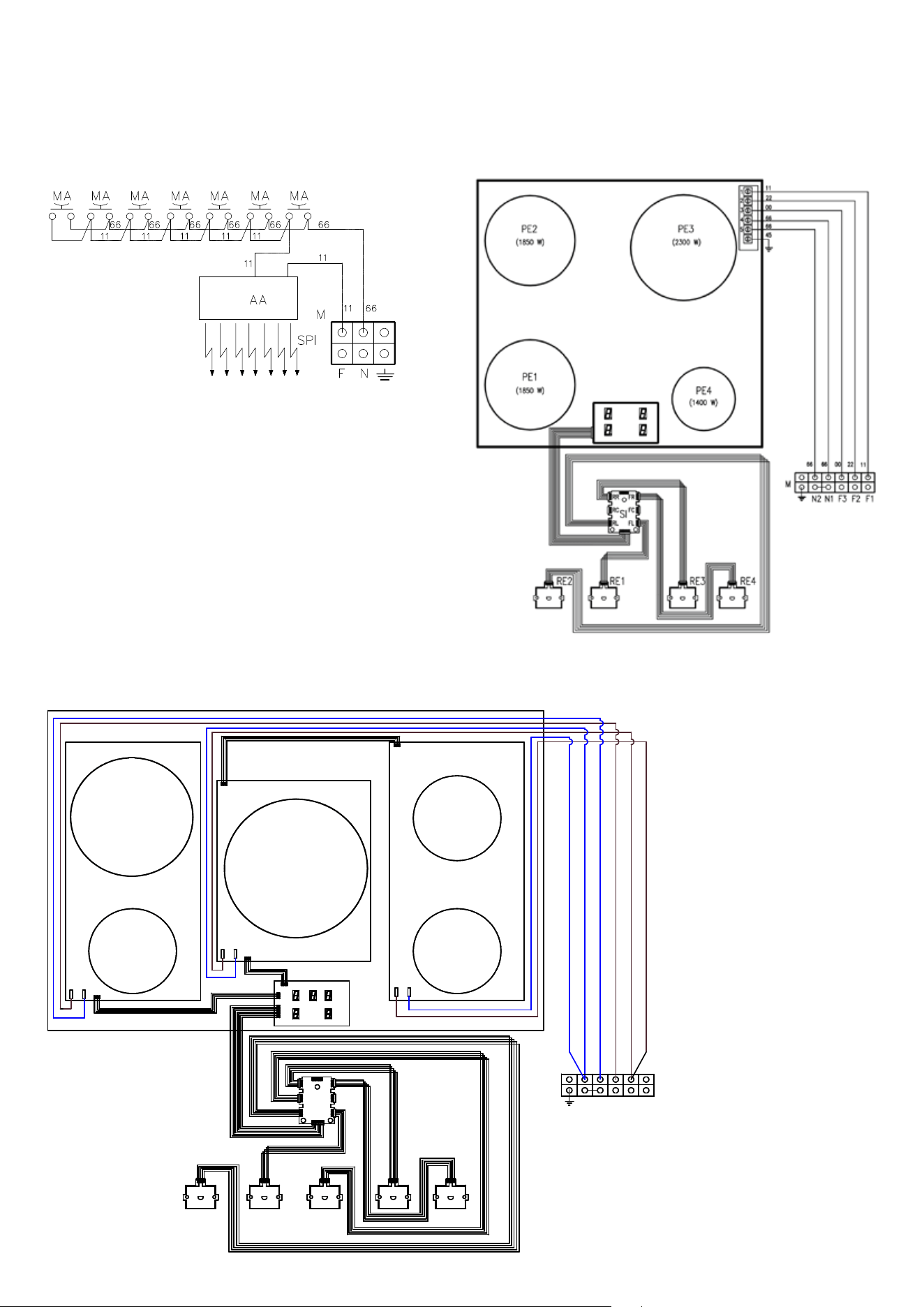
38
INSTALLATION
Wiring diagrams
GAS HOB 4 INDUCTION ZONES
N2 N1 F3 F2 F1
M
6666
11
11
11
SI
4ER1ER 3ER2ER
P1 d.160 mm
(1100/1400 W)
RE5
RR
RC
RL
FR
FC
FL
X1/L
X2/N
X1
X2
X1/L
X2/N
X1/L
X2/N
X6
X6
X18
X18
X8
11
11
66
66
11
66
66
11
11
66
66
11
66
66 66 66 11 11 11
45
SD
75.08014.710
75.08014.860
75.08014.110
P2 d.200 mm
(2300/3000 W)
75.471.160
75.471.096
P5 d.250 mm
(2300/3000 W)
75.471.097
P3 d.160 mm
(1400/2000 W)
75.471.173
P4 d.160 mm
(1100/1400 W)
75.471.160
5 INDUCTION ZONES BASIC
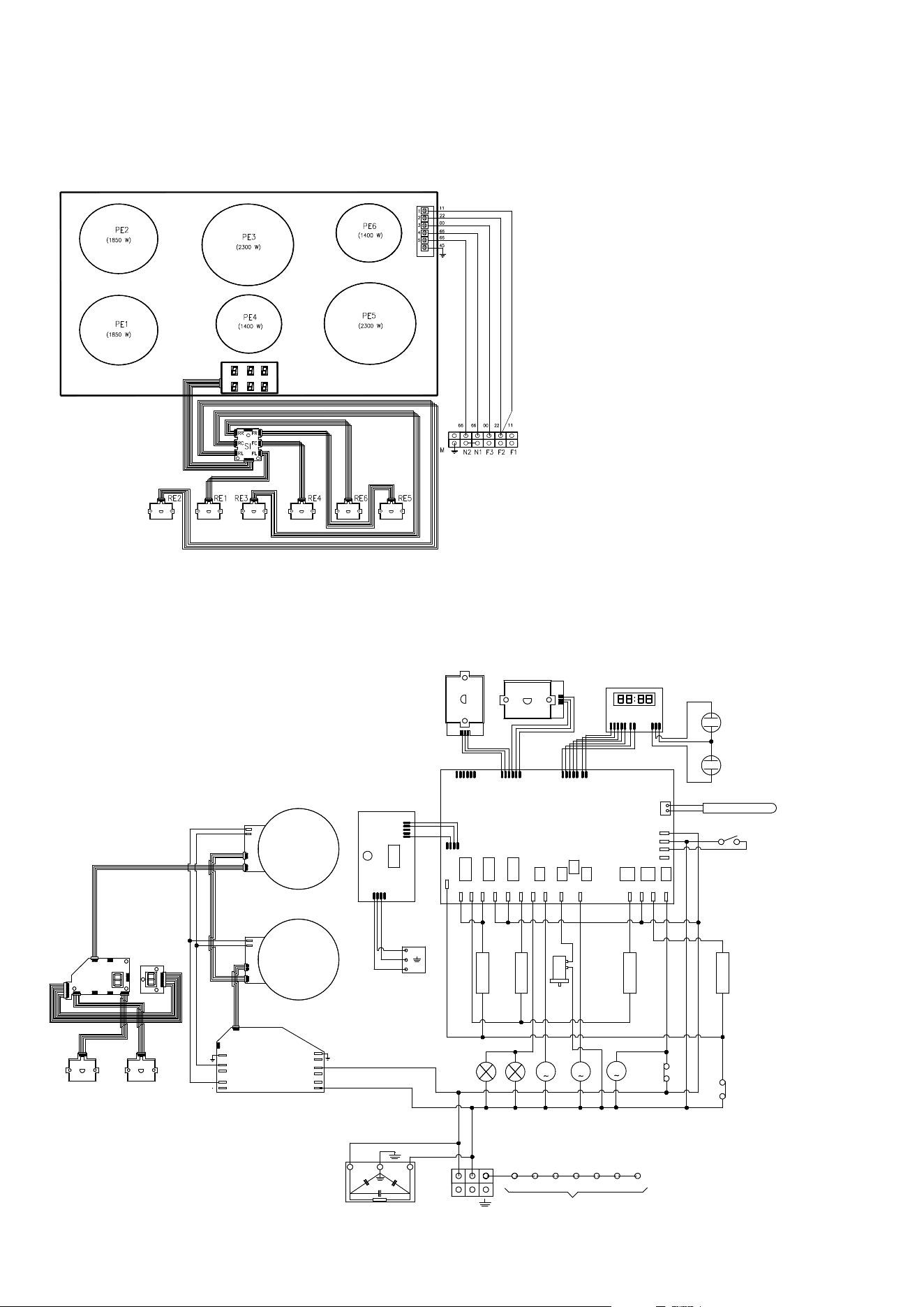
39
P09I...E3
P38
P9
P8 P19 P14 P28 P27 P7 P34 P33 P13 P5 P10 P26
P18
P12
P15
P16
P_DISPPOT_1_2POT_3_4
P17
N F
M
66
11
K2K1 K4K3 K6
45
K5
K15
M
V
66
66
66
66
66
11
11
M
L1
VT
R4 R3 R2
TS
R1
1111111111
66
33
33
44
44
11
11
00
00
22
55
22
55
55
00
00
00
00
00
00
11
11
11
11
11
33
33
66
11 11
11
11
SP
NTC
SW1
L2
33
M
MG
22
22
ET
EF
S2
S1
P1 P2
66
33
00
SD
B
C
A
66
45
11
CP
SS
FLC
MP
P23
DU
11
11
11
33
X13
X14
X10
X9
X15
X3
X4
X2
X1
X5
X6
P1
P2
X1
X2
X200
X201
X1
X2
X200
X201
RE1RE2
X6 X7
X8
X4 X3 X2
X5
X1.4
X8
X7
11
SP
SI
SD
66
66
66
66
66
1111
11
11
11
66
11
45
45
11
11
66
TT
INSTALLATION
Wiring diagrams
6 INDUCTION ZONES
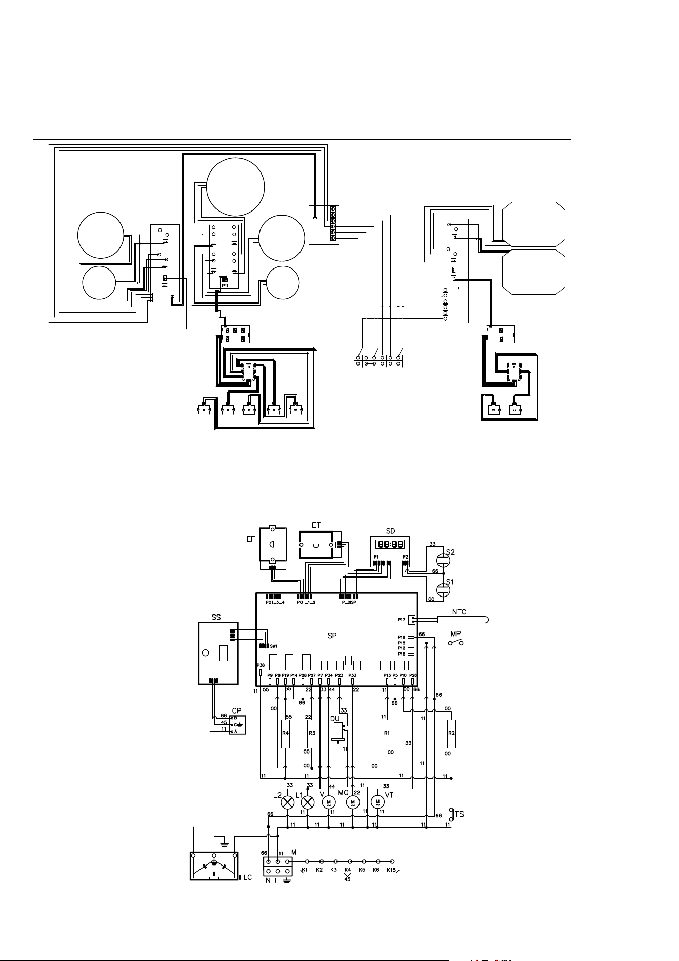
40
INSTALLATION
Wiring diagrams
7 INDUCTION ZONES
PE5
PE4
SI
5ER2ER 4ER1ER
RR
RC
RL
FR
FC
FL
1
2
3
4
5
M
11
11
66
66
45
N N F3
F2
F1
11
11
11
11
66
66
45
45
66
11 11
66
66
66
X1110
X1100
X2100
X2110
66
00
66
00
66
00
X401
X402
DY
11
11
11
11
PE3
(2300/3000 W)
(2300/3000 W)
(1400/1850 W)
X1100
X1200
66
00
X401
X402
X1110
X1210
PE2
PE1
(2300/3000 W)
(1400/1850 W)
66
X201
X1400
X1410
X1100
X2100
X201
PE
N1
L3
45
66
11
45
66
11
RE3
X1110
X1100
X2210
X2200
X1100
X2210
00
66
00
66
0000
6666
00
66
X17
X13
X7
00
45
45
66
11
45
66
11
66
11
X1100
X1200
X401
X402
X1110
X1210
X1400
X1410
1
2
3
4
5
PE
N1
L3
66
00
66
00
66
00
66
00
SI
RE6
RR
RC
RL
FR
FC
FL
DY
RE3
11
66
45
PE6
(2300/3000 W)
PE7
(2300/3000 W)
P (06-07-30”-08-09)...E3
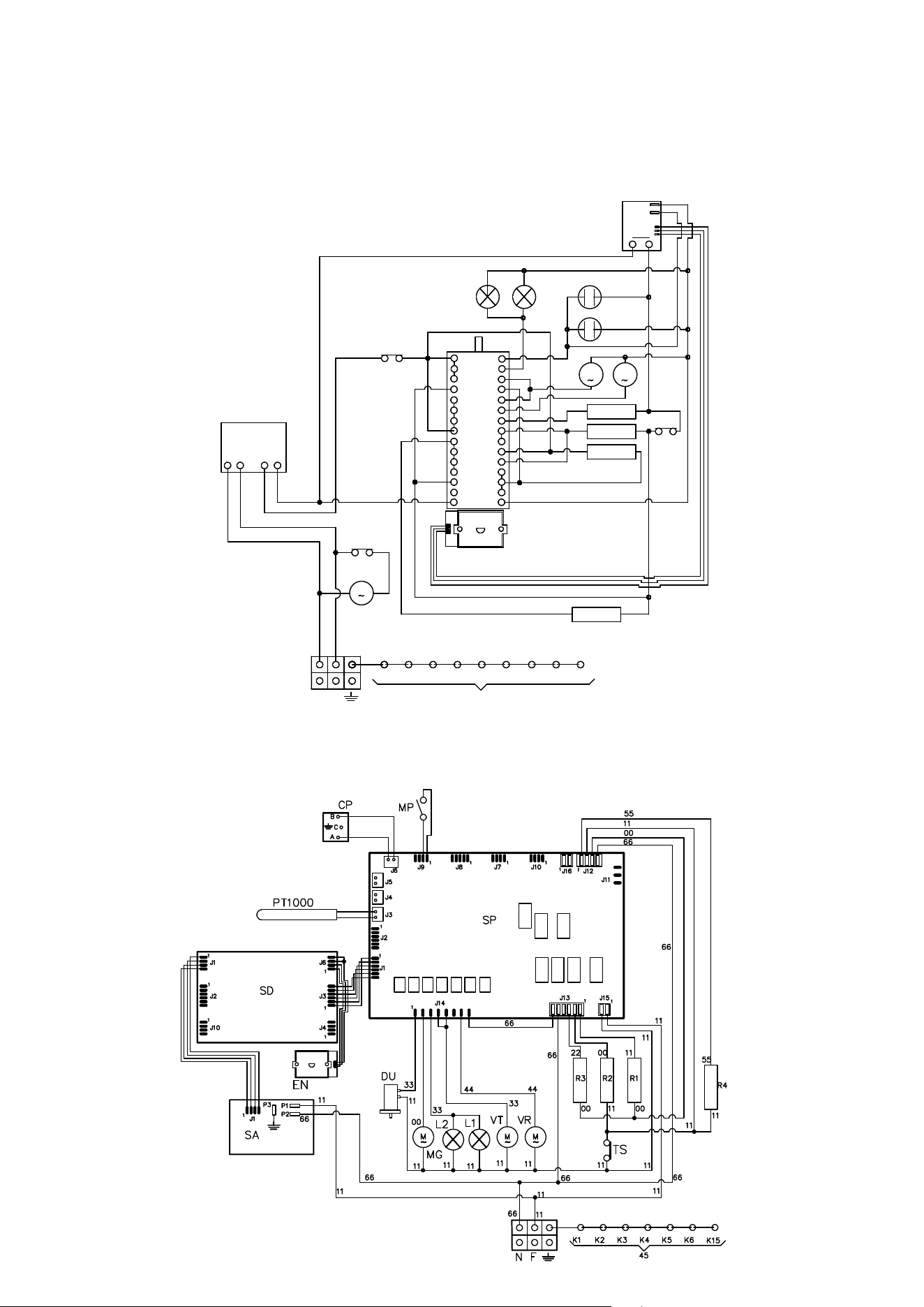
41
INSTALLATION
Wiring diagrams
L7P (06-09)...M3
C mf
5
4
8
6
7
11
9
10
C
E
G
M
I
L
3
12
N
D
F
H
O
13
EF
2
A 1
B
P
14
K1
45
K3 K5 K6
N F
M
K7 K9 K13 K15K8
TS
66
11
11
11
M
VT
11
TT
66
P
IN
OUT
66
66
11
11
11
66
66
R4 mf
11
55
R1 mf
R2 mf
11
00
00
00
R3 mf
22
T
33
S1
S2
00
66
M
M
MG
VR
L1
L2
00
00
00
22
22
66
66
66
66
66
33
33
33
66
44
66
33
33
66
66
66
66
66
11
Q
15
MP
11
11
00
00
11
M (07-30”-09)...E3
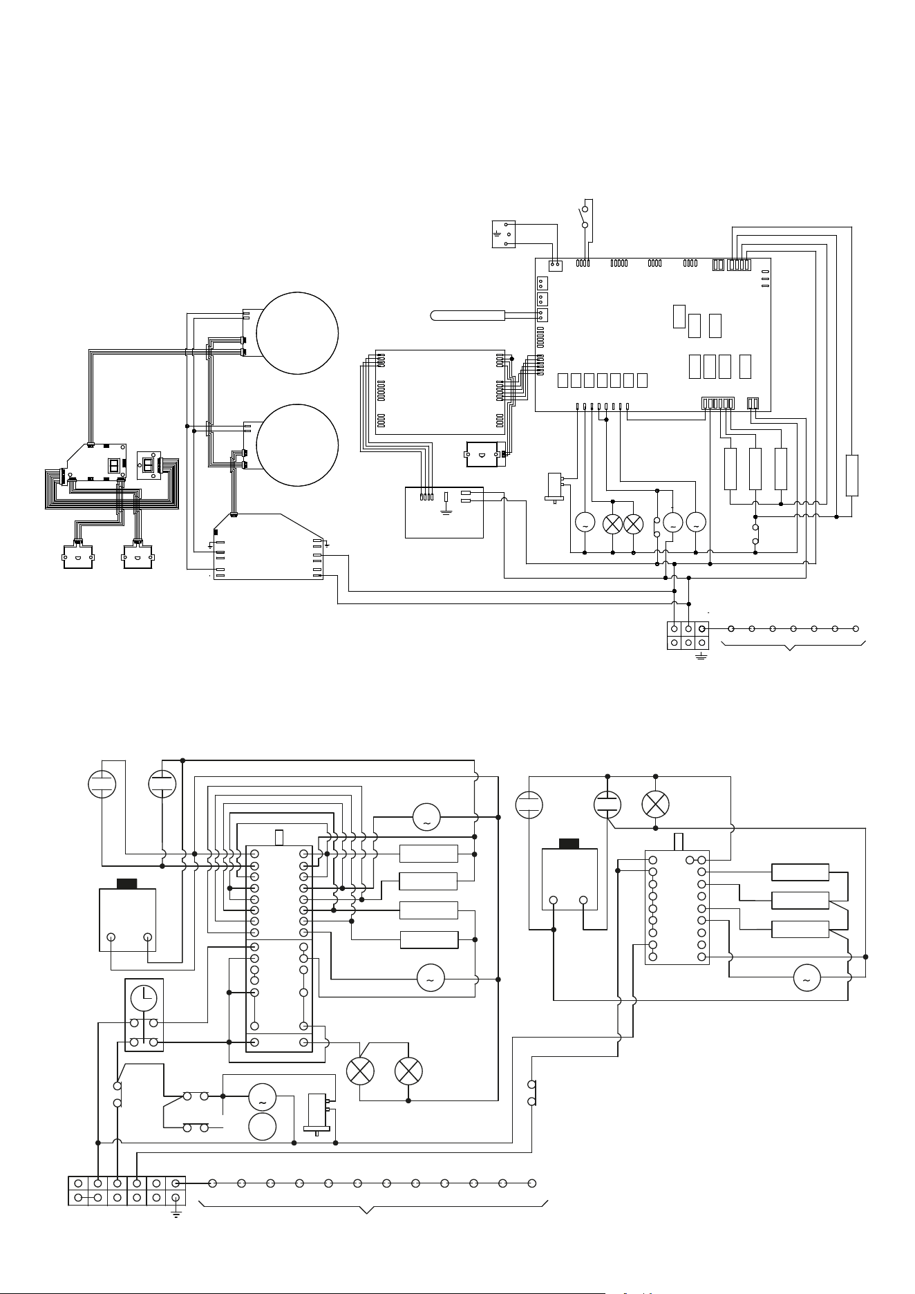
42
INSTALLATION
Wiring diagrams
M09I..E3
J11
SP
J12J16
J10J7J8J9
J6
J5
J4
J3
J2
J1
J14
J13 J15
1111
1
1
1
1
1
DU
M
MG
L1
L2
M
VT
M
VR
R3
22
00
R2
00
11
R1
11
00
66
33
44
44
R4
55
11
TS
N F
66
11
K2K1 K4K3 K6
45
K5
K15
PT1000
B
C
A
CP
MP
J3
J6
J4
1
1
1
1
1
J2
J1
J10
1
1
1
P1
P2
P3
J1
1
11
11
11
11
11
11
33
00
33
00
66
66
66
66
66
11
11
11
66
66
55
11
11
11
11
11
11
SD
SA
X13
X14
X10
X9
X15
X3
X4
X2
X1
X5
X6
P1
P2
X1
X2
X200
X201
X1
X2
X200
X201
RE1RE2
X6 X7
X8
X4 X3 X2
X5
X1.4
X8
X7
11
SP
SI
SD
66
66
66
66
66
1111
11
11
11
66
11
45
45
EN
TT
66
L/P 12...M3
C
K
I
10
16
14
12
9
11
13
15
J
M
P
2
8
6
4
1
3
5
7
C
A
B
E
H
D
2
1
P
M
VT
TS
M
11
11
TT
66
66
66
11
11
11
11
11
66
L1
L2
33
11
R1
22
R3
00
R2
55
R4
44
M
V
S2
S1
2
1
TF
66
66 66
11
11
00
00
00
00
00
00
33
66
66
66
66
66
66
66
66
66
66
00
00
00
33
33
33
00
00
0000
22
22
00
11
11
11 00
44
44
55
00
00
22
44
11
55
33
TS
K12
K1
45
K4
K2 K3 K5
K6
K7 K8 K11
K9 K15
11
66
11
TT
M
MG*
66
22
66
22
33
M
MG
L1
33
S1
2
1
C
S2
66
3
2
R3
R1
44
TF
00
66
66
00
00
00
6
4
5
9
7
8
A
B
F
D
I
G
H
1
R2
33
66
00
22
55
00
66
66
00
33
33
66
11
11
11
66
66
11
N2 N1 F3 F2 F1
M
DUst
33
M
VT
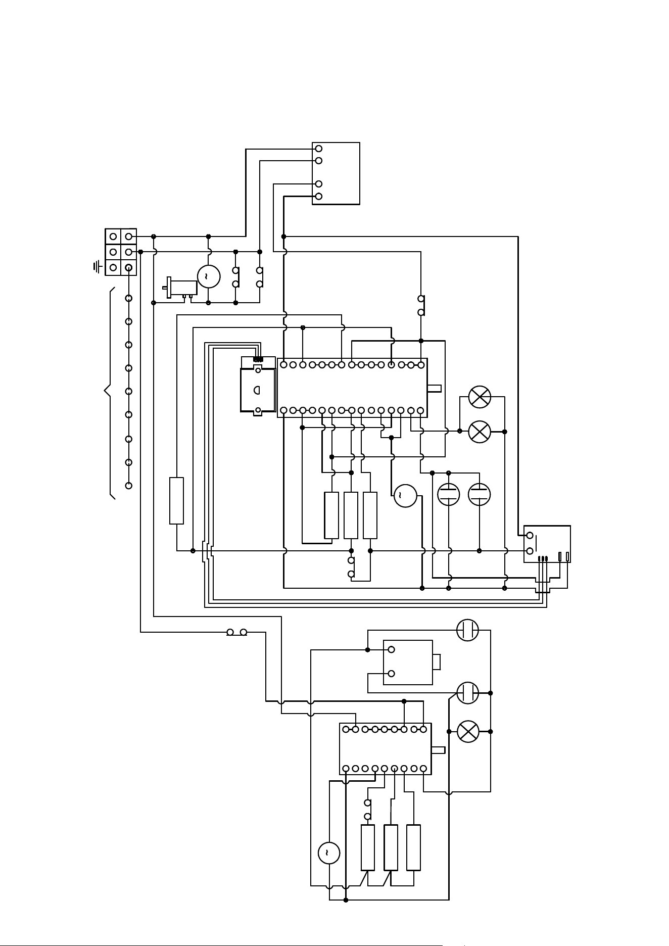
43
INSTALLATION
Wiring diagrams
LD (09-10)...M3
C mf
5
4
8
6
7
11
9
10
C
E
G
M
I
L
3
12
N
D
F
H
O
13
EF
2
A 1
B
P
14
K1
45
K3 K5 K6
N F
M
K7 K9 K13 K15K8
TS
66
11
11
11
M
VT
11
TT
66
P
IN
OUT
66
66
11
11
11
66
66
R4 mf
11
55
R1 mf
R2 mf
11
00
00
00
R3 mf
22
T
33
S1
S2
00
66
M
VR
L1
L2
00
00
00
22
22
66
66
66
66
66
33
33
33
66
44
66
33
33
66
66
66
66
66
11
Q
15
MP
33
M
33
2
1
66
3
2
R1
R2
55
TF
00
66
66
00
00
00
6
4
5
9
7
8
A
B
F
D
I
G
H
1
R3
33
66
00
44
22
00
66
66
00
33
33
66
11
11
11
66
66
11
11
66
66
S1
S2
L1
C st
MG
TS
MP
TT
DUst
66
1111
00
00
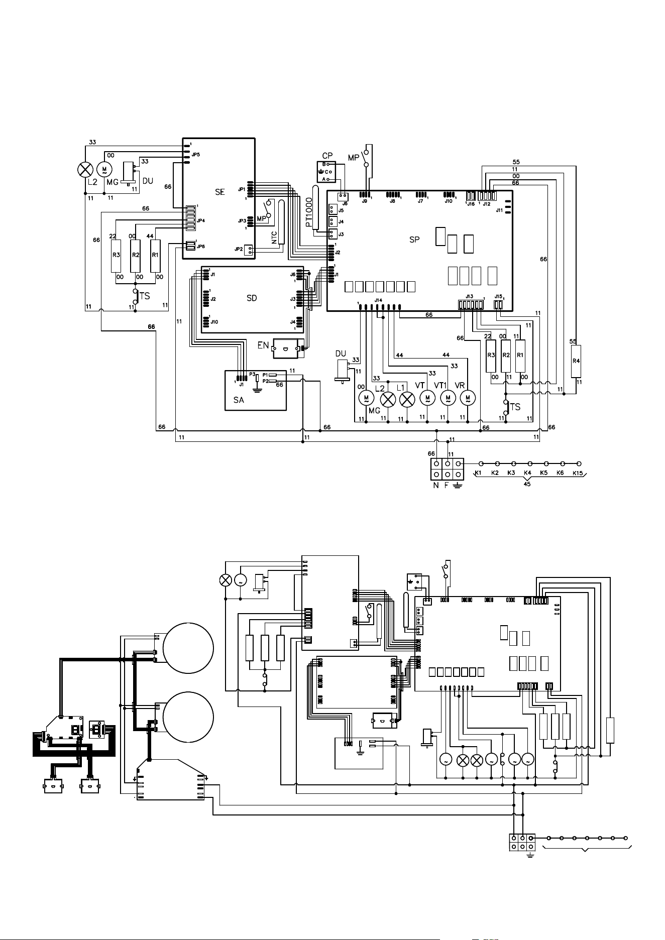
44
INSTALLATION
Wiring diagrams
M12...E3
M12I...E3
J11
SP
J12J16
J10J7J8J9
J6
J5
J4
J3
J2
J1
J14
J13 J15
1111
1
1
1
1
1
DU
M
MG
L1
L2
M
VT
M
VT1
R3
22
00
R2
00
11
R1
11
00
66
33
44
44
R4
55
11
TS
N F
66
11
K2K1 K4K3 K6
45
K5
K15
B
C
A
CP
MP
J3
J6
J4
1
1
1
1
1
J2
J1
J10
1
1
1
P1
P2
P3
J1
1
11
11
11
11
11
11
11
33
00
33
00
66
66
66
66
66
11
11
11
66
66
55
11
11
11
11
11
11
JP2
JP1
1
1
JP3
1
JP5
JP6
JP4
1
1
PT1000
DU
M
MG
L2
11
SD
SE
11
11
11
11
66
66
33
00
33
M
VR
11
33
SA
X13
X14
X10
X9
X15
X3
X4
X2
X1
X5
X6
P1
P2
X1
X2
X200
X201
X1
X2
X200
X201
RE1RE2
X6 X7
X8
X4 X3 X2
X5
X1.4
X8
X7
11
SP
SI
SD
66
66
66
66
66
1111
11
11
11
66
11
45
45
11
66
66
EN
NTC
MP
R3
22
00
R2
00
00
R1
44
00
TS
11
11
11
66
66
66
TT
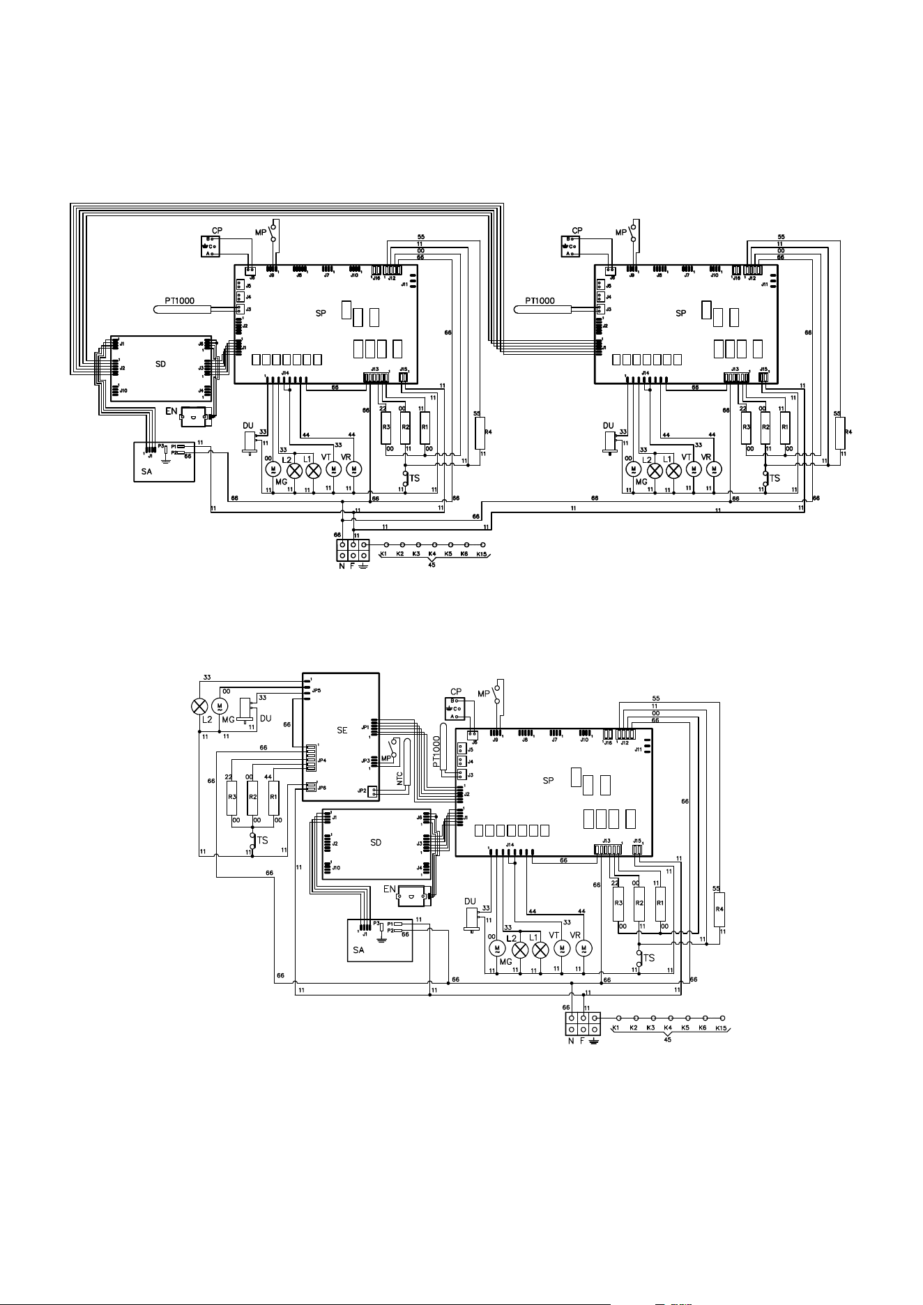
45
INSTALLAZIONE
Wiring diagrams
M15...E3
MD10...E3
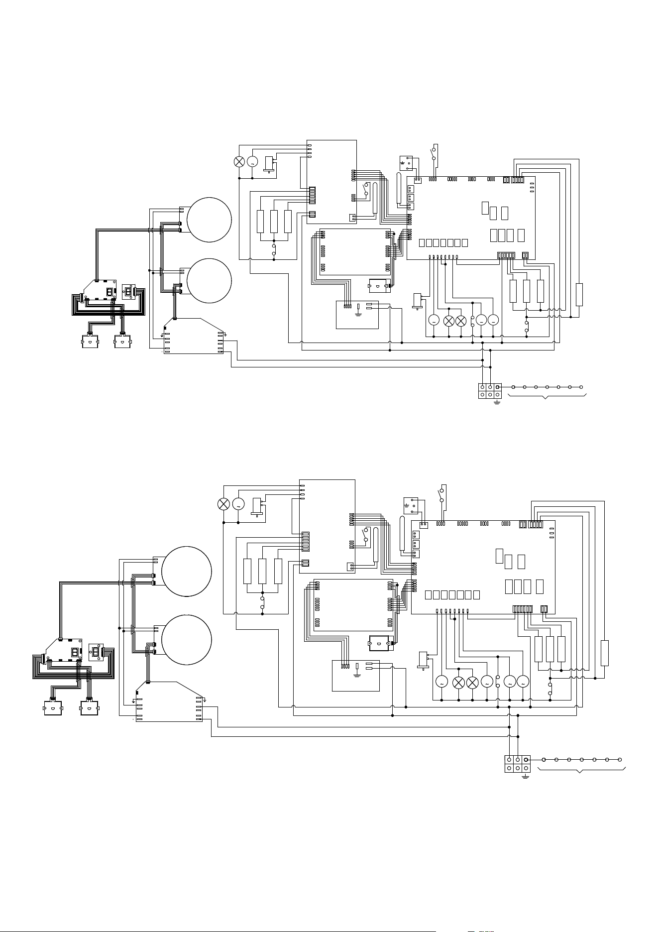
46
INSTALLAZIONE
Wiring diagrams
MD10I...E3
J11
SP
J12J16
J10J7J8J9
J6
J5
J4
J3
J2
J1
J14
J13 J15
1111
1
1
1
1
1
DU
M
MG
L1
L2
M
VT
M
VR
R3
22
00
R2
00
11
R1
11
00
66
33
44
44
R4
55
11
TS
N F
66
11
K2K1 K4K3 K6
45
K5
K15
B
C
A
CP
MP
J3
J6
J4
1
1
1
1
1
J2
J1
J10
1
1
1
P1
P2
P3
J1
1
11
11
11
11
11
11
11
33
00
33
00
66
66
66
66
66
11
11
11
66
66
55
11
11
11
11
11
11
JP2
JP1
1
1
JP3
1
JP5
JP6
JP4
1
1
PT1000
DU
M
MG
L2
11
SD
SE
11
11
11
11
66
66
33
00
33
SA
X13
X14
X10
X9
X15
X3
X4
X2
X1
X5
X6
P1
P2
X1
X2
X200
X201
X1
X2
X200
X201
RE1RE2
X6 X7
X8
X4 X3 X2
X5
X1.4
X8
X7
11
SP
SI
SD
66
66
66
66
66
1111
11
11
11
66
11
45
45
11
11
11
66
66
66
EN
NTC
MP
R3
22
00
R2
00
00
R1
44
00
TS
11
11
11
66
66
66
TT
P12...IE3
J11
SP
J12J16
J10J7J8J9
J6
J5
J4
J3
J2
J1
J14
J13 J15
1111
1
1
1
1
1
DU
M
MG
L1
L2
M
VT
M
VT1
R3
22
00
R2
00
11
R1
11
00
66
33
44
44
R4
55
11
TS
N F
66
11
K2K1 K4K3 K6
45
K5
K15
B
C
A
CP
MP
J3
J6
J4
1
1
1
1
1
J2
J1
J10
1
1
1
P1
P2
P3
J1
1
11
11
11
11
11
11
11
33
00
33
00
66
66
66
66
66
11
11
11
66
66
55
11
11
11
11
11
11
JP2
JP1
1
1
JP3
1
JP5
JP6
JP4
1
1
PT1000
DU
M
MG
L2
11
SD
SE
11
11
11
11
66
66
33
00
33
M
VR
11
33
SA
X13
X14
X10
X9
X15
X3
X4
X2
X1
X5
X6
P1
P2
X1
X2
X200
X201
X1
X2
X200
X201
RE1RE2
X6 X7
X8
X4 X3 X2
X5
X1.4
X8
X7
11
SP
SI
SD
66
66
66
66
66
1111
11
11
11
66
11
45
45
11
66
66
EN
NTC
MP
R3
22
00
R2
00
00
R1
44
00
TS
11
11
11
66
66
66
TT
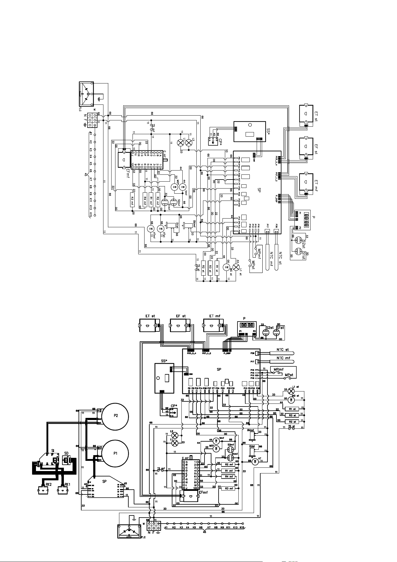
47
INSTALLATION
Wiring diagrams
P12...E3
PD(09/10)I...E3
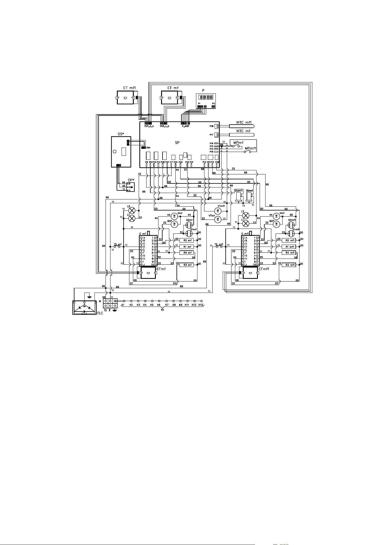
48
INSTALLATION
Wiring diagrams
P15...E3
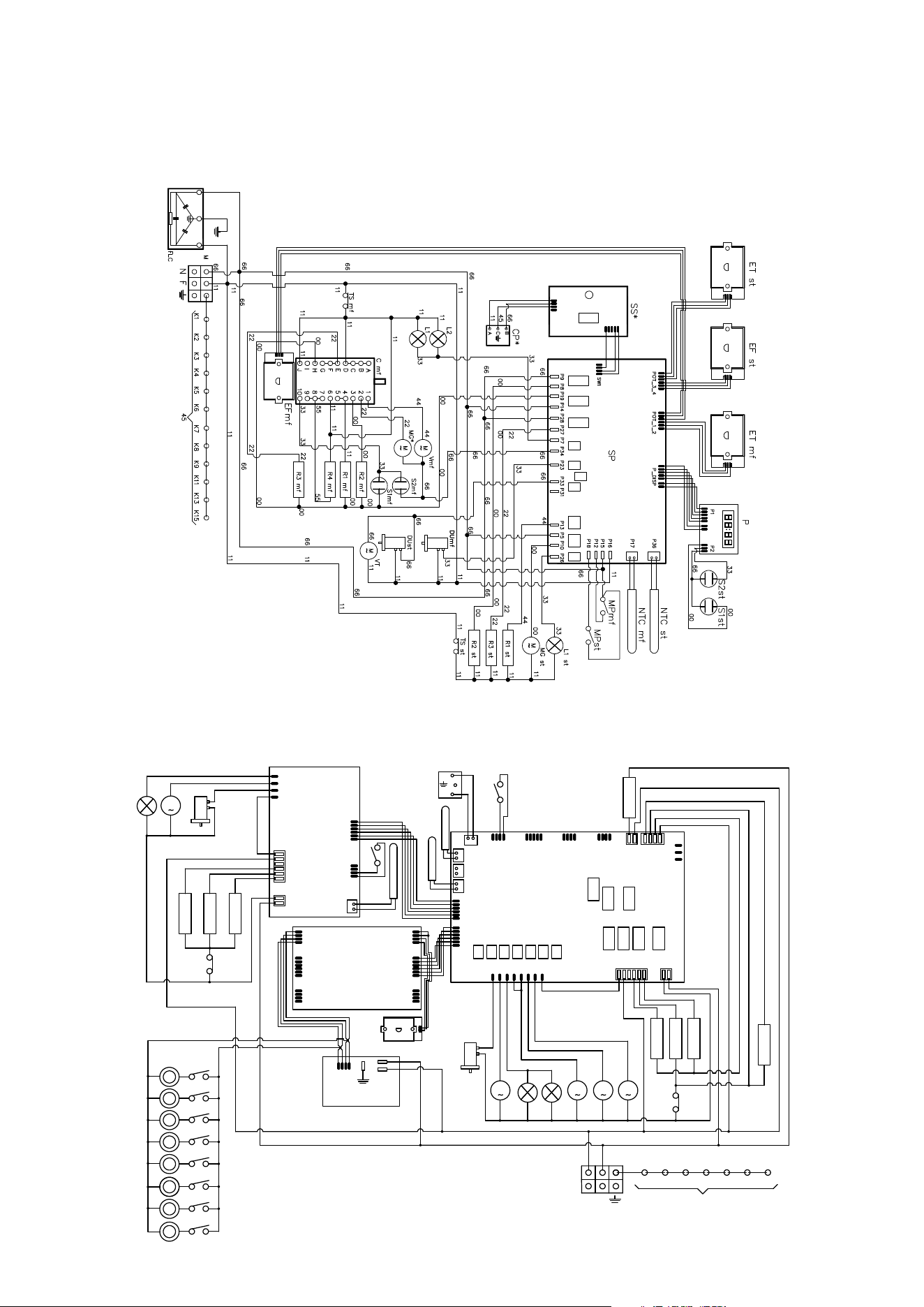
49
INSTALLATION
Wiring diagrams
PD(09/10)...E3
PM12S3
Schema elettrico forno cucine
N.F.
/
/
01/07/2019
/
Sost. il N°
DISEGNO N°
Trattamento
Quantità
pezzi
Il presente disegno non può essere riprodotto, utilizzato o comunicato a terzi.
Dimensione grezzo
Denominazione
Scala
MODIFICHE
N°
MATERIALE
Peso grezzo
Denominazione
Data
Dis.
Q.tà
Dimensione finita
Peso finito
N° Attrezzatura
Classifica
Materiale
Tolleranza
Gruppo
Disegno
Prodotto
CAMPODARSEGO PD
S.P.A.
UFFICIO TECNICO
Classifica
LEGENDA
_ VT
_ TS
_ L1
_ VR
_ M
_ 00
_ 11
_ 22
_ 33
_ 44
_ 45
_ 55
_ 66
_ K1
_ K2
_ K3
_ K4
_ K5
_ K6
_ R1
_ R2
_ R3
_ R4
= Ventilatore tangenziale
= Termostato di sicurezza
= Luce forno
= Ventilatore radiale
= Morsettiera
= Nero
= Marrone
= Rosso
= Bianco
= Giallo
= Giallo-Verde
= Grigio
= Blu
= Filo terra morsettiera
= " " res. suola
= " " motovent. radiale
= " " res. circolare
= " " res. cielo
= " " luce forno 1
= Resist. cielo
= Resist. suola
= Resist. grill
= Resist. circolare
_ F
_ N
= Fase
= Neutro
_ K15
= " " telaio
_ SP
= Scheda potenza
_ SD
= Scheda display
_ CP
= Collegamento sonda cottura
_ L2
= Luce forno
_ MP
= Micro porta
_ DU
= Termoattuatore a cera scarico vapore
_ MG
= Motore girarrosto
J11
SP
J12J16
J10J7J8J9
J6
J5
J4
J3
J2
J1
J14
J13 J15
1111
1
1
1
1
1
DU
M
MG
L1
L2
M
VT
M
VT1
R3
22
00
R2
00
11
R1
11
00
66
33
44
44
R4
55
11
TS
N
F
66
11
K2K1 K4K3
K6
45
K5
K15
B
C
A
CP
MP
J3
J6
J4
1
1
1
1
1
J2
J1
J10
1
1
1
P1
P2
P3
J1
1
PM12S3
11
11
11
11
11
11
11
33
00
33
00
66
66
66
66
66
11
11
11
66
66
55
11
11
11
11
11
11
JP2
JP1
1
1
JP3
1
JP5
JP6
JP4
1
1
PT1000
DU
M
MG
L2
11
SD
SE
11
11
11
11
11
66
66
33
00
33
_ SE
= Scheda estensione
M
VR
11
33
_ VT1
= Ventilatore tangenzialeforno statico
SA
_ SA
= Scheda alimentatore
EN
_ EN
= Encoder
NTC
MP
66
R3
22
00
R2
00
00
R1
44
00
TS
11
11
11
66
66
66
GL
GL
GL
GL
GL
GL
MGL
MGL
MGL
MGL
MGL
MGL
GL
GL
MGL
MGL
_ MGL
= Micro ghiera led
_ GL
= Ghiera led
R5
11
66
6666
11
11
_ R5
= Resist. cassetto
NTC
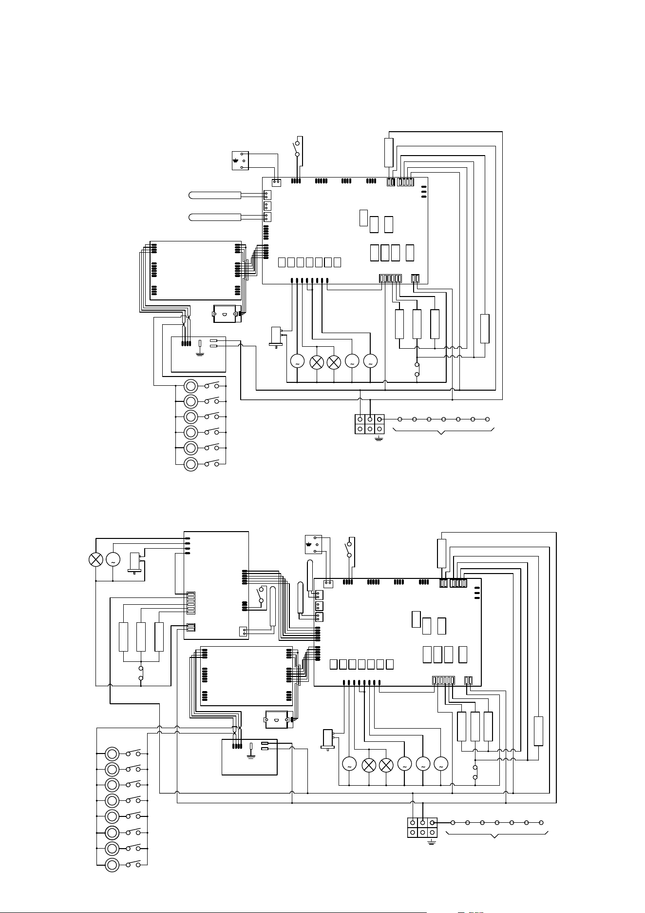
50
INSTALLATION
Wiring diagrams
PM096S3
J11
SP
J12J16
J10J7J8J9
J6
J5
J4
J3
J2
J1
J14
J13 J15
1111
1
1
1
1
1
DU
M
MG
L1
L2
M
VT
M
VR
R3
22
00
R2
00
11
R1
11
00
66
33
44
44
R4
55
11
TS
N F
66
11
K2K1 K4K3 K6
45
K5
K15
PT1000
B
C
A
CP
MP
J3
J6
J4
1
1
1
1
1
J2
J1
J10
1
1
1
P1
P2
P3
J1
1
11
11
11
11
11
11
11
33
00
33
00
66
66
66
66
66
11
11
11
66
66
55
11
11
11
11
11
11
SD
SA
EN
GL
GL
GL
GL
GL
GL
MGL
MGL
MGL
MGL
MGL
MGL
R5
11
1111
66
66
NTC
PM12S3
Schema elettrico forno cucine
N.F.
/
/
01/07/2019
/
Sost. il N°
DISEGNO N°
Trattamento
Quantità
pezzi
Il presente disegno non può essere riprodotto, utilizzato o comunicato a terzi.
Dimensione grezzo
Denominazione
Scala
MODIFICHE
N°
MATERIALE
Peso grezzo
Denominazione
Data
Dis.
Q.tà
Dimensione finita
Peso finito
N° Attrezzatura
Classifica
Materiale
Tolleranza
Gruppo
Disegno
Prodotto
CAMPODARSEGO PD
S.P.A.
UFFICIO TECNICO
Classifica
LEGENDA
_ VT
_ TS
_ L1
_ VR
_ M
_ 00
_ 11
_ 22
_ 33
_ 44
_ 45
_ 55
_ 66
_ K1
_ K2
_ K3
_ K4
_ K5
_ K6
_ R1
_ R2
_ R3
_ R4
= Ventilatore tangenziale
= Termostato di sicurezza
= Luce forno
= Ventilatore radiale
= Morsettiera
= Nero
= Marrone
= Rosso
= Bianco
= Giallo
= Giallo-Verde
= Grigio
= Blu
= Filo terra morsettiera
= " " res. suola
= " " motovent. radiale
= " " res. circolare
= " " res. cielo
= " " luce forno 1
= Resist. cielo
= Resist. suola
= Resist. grill
= Resist. circolare
_ F
_ N
= Fase
= Neutro
_ K15
= " " telaio
_ SP
= Scheda potenza
_ SD
= Scheda display
_ CP
= Collegamento sonda cottura
_ L2
= Luce forno
_ MP
= Micro porta
_ DU
= Termoattuatore a cera scarico vapore
_ MG
= Motore girarrosto
J11
SP
J12J16
J10J7J8J9
J6
J5
J4
J3
J2
J1
J14
J13 J15
1111
1
1
1
1
1
DU
M
MG
L1
L2
M
VT
M
VT1
R3
22
00
R2
00
11
R1
11
00
66
33
44
44
R4
55
11
TS
N
F
66
11
K2K1 K4K3
K6
45
K5
K15
B
C
A
CP
MP
J3
J6
J4
1
1
1
1
1
J2
J1
J10
1
1
1
P1
P2
P3
J1
1
PM12S3
11
11
11
11
11
11
11
33
00
33
00
66
66
66
66
66
11
11
11
66
66
55
11
11
11
11
11
11
JP2
JP1
1
1
JP3
1
JP5
JP6
JP4
1
1
PT1000
DU
M
MG
L2
11
SD
SE
11
11
11
11
11
66
66
33
00
33
_ SE
= Scheda estensione
M
VR
11
33
_ VT1
= Ventilatore tangenzialeforno statico
SA
_ SA
= Scheda alimentatore
EN
_ EN
= Encoder
NTC
MP
66
R3
22
00
R2
00
00
R1
44
00
TS
11
11
11
66
66
66
GL
GL
GL
GL
GL
GL
MGL
MGL
MGL
MGL
MGL
MGL
GL
GL
MGL
MGL
_ MGL
= Micro ghiera led
_ GL
= Ghiera led
R5
11
66
6666
11
11
_ R5
= Resist. cassetto
NTC
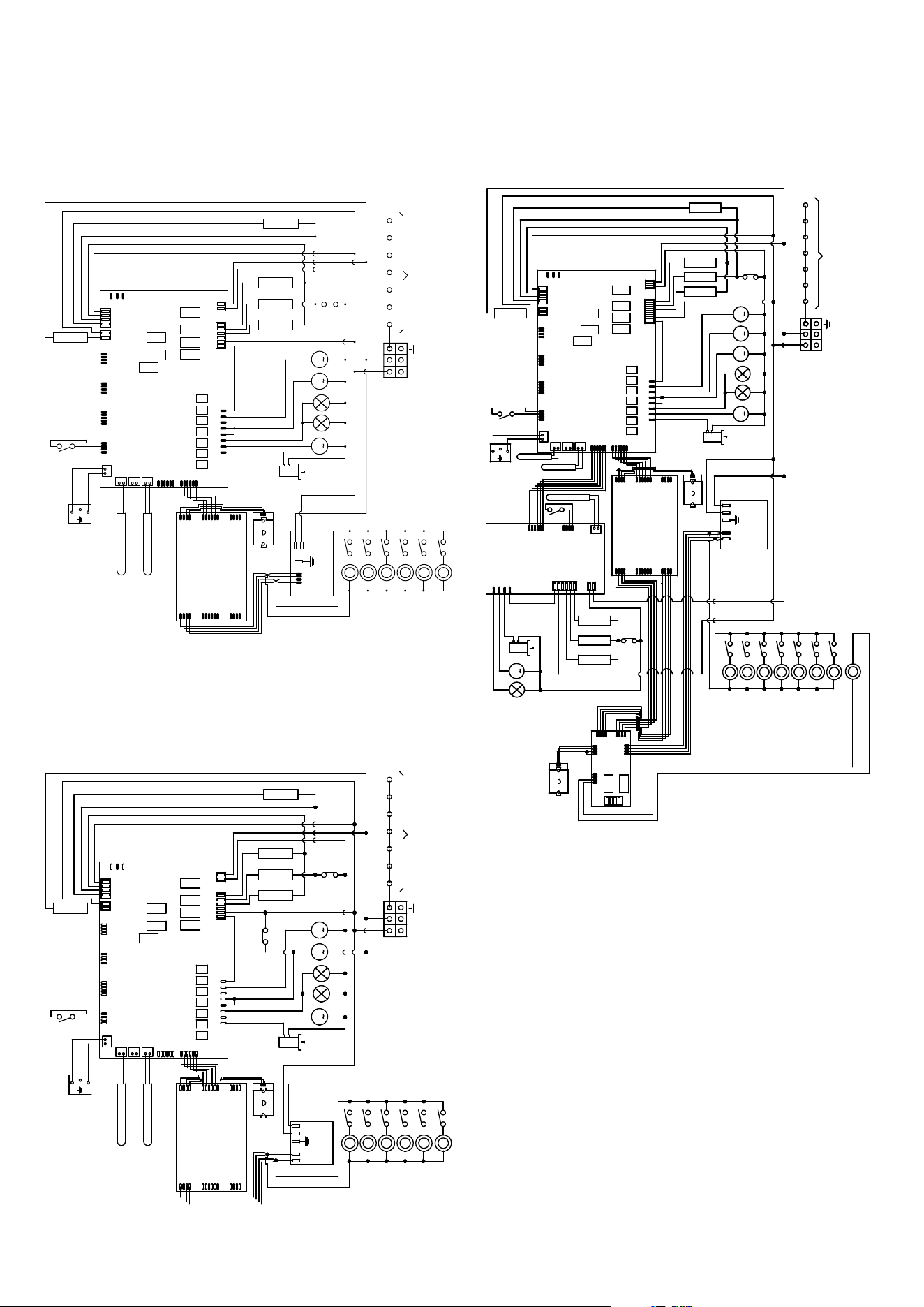
51
INSTALLATION
Wiring diagrams
PMI12S3
J11
SP
J12J16
J10J7J8J9
J6
J5
J4
J3
J2
J1
J14
J13 J15
1111
1
1
1
1
1
DU
M
MG
L1
L2
M
VT
M
VT1
R3
22
00
R2
00
11
R1
11
00
66
33
44
44
R4
55
11
TS
N F
66
11
K2K1 K4K3 K6
45
K5
K15
B
C
A
CP
MP
J3
J6
J4
1
1
1
1
1
J2
J1
J10
1
1
1
11
11
11
11
11
11
11
33
00
33
00
66
66
66
66
11
11
66
66
55
11
11
11
11
11
11
JP2
JP1
1
1
JP3
1
JP5
JP6
JP4
1
1
PT1000
DU
M
MG
L2
11
SD
SE
11
11
11
11
11
66
66
33
00
33
M
VR
11
33
EN
NTC
MP
R3
22
00
R2
00
00
R1
44
00
TS
11
11
11
66
66
66
GL
GL
GL
GL
GL
GL
MGL
MGL
MGL
MGL
MGL
MGL
GL
MGL
R5
11
66
6666
11
11
NTC
L
SA
NV-V+
66
11
J6
1
J4
1
J3
1
J1
J5
1
1
J7
EN
SWD
GL
PMI09S3
J11
SP
J12J16
J10J7J8J9
J6
J5
J4
J3
J2
J1
J14
J13 J15
1111
1
1
1
1
1
DU
M
MG
L1
L2
M
VT
M
VR
R3
22
00
R2
00
11
R1
11
00
66
33
44
44
R4
55
11
TS
N F
66
11
K2K1 K4K3 K6
45
K5
K15
PT1000
B
C
A
CP
MP
J3
J6
J4
1
1
1
1
1
J2
J1
J10
1
1
1
11
11
11
11
11
11
11
33
00
33
00
66
66
66
66
11
11
11
66
66
55
11
11
11
11
11
11
SD
SA
EN
GL
GL
GL
GL
GL
GL
MGL
MGL
MGL
MGL
MGL
MGL
R5
11
1111
66
66
NTC
L
N
V-
V+
TT
11
66
PM096S3
J11
SP
J12J16
J10J7J8J9
J6
J5
J4
J3
J2
J1
J14
J13 J15
1111
1
1
1
1
1
DU
M
MG
L1
L2
M
VT
M
VR
R3
22
00
R2
00
11
R1
11
00
66
33
44
44
R4
55
11
TS
N F
66
11
K2K1 K4K3 K6
45
K5
K15
PT1000
B
C
A
CP
MP
J3
J6
J4
1
1
1
1
1
J2
J1
J10
1
1
1
P1
P2
P3
J1
1
11
11
11
11
11
11
11
33
00
33
00
66
66
66
66
66
11
11
11
66
66
55
11
11
11
11
11
11
SD
SA
EN
GL
GL
GL
GL
GL
GL
MGL
MGL
MGL
MGL
MGL
MGL
R5
11
1111
66
66
NTC

52
ILVE AUS & NZ PTY LTD
10/60 York Street
Sydney NSW 2000
tel. 02 92209600
WARRANTY REGISTRATION
Your ongoing satisfaction with your ILVE product is important to us.
We ask that you complete the enclosed Warranty Registration Card
and return it to us so that we have a record of the ILVE product pur-
chased by you.
PRIVACY
ILVE respects your privacy and is committed to handling your per-
sonal information in accordance with the National Privacy Principles
and the Privacy Act 1988 (Cth). ILVE will not disclose any personal
information set out in the Warranty Registration Card (“Personal In-
formation”) without your consent unless required by:
1. law;
2. any ILVE related company;
3. any service provider which provide services to ILVE or assist ILVE
in providing services (including repair and warranty services) to
customers. Our purpose in collecting the Personal Information is to
keep a record of the ILVE product purchased by you, in order to pro-
vide a better warranty service to you in the unlikely event that there is
a problem with your ILVE product. ILVE may contact you at any one
or more of the addresses, email addresses or telephone numbers
set out in the Warranty Registration Card.
WARRANTY
1. Warranty
ILVE warrants that each ILVE product will remain, for a period of
twenty four (24) months computed from the date of purchase of the
ILVE product, free from defects arising in the
manufacture of the ILVE product (“Warranty”). Except for consum-
er guarantees set out in the Competition and Consumer Act 2010
(Cth) (“Act”), ILVE does not make any further
warranties or representations in relation to ILVE products.
2. What is not Covered by the Warranty.
The Warranty does not apply if an ILVE product is defective by a fac-
tor other than a defect arising in the manufacture of the ILVE prod-
uct, including but not limited to:
(a) damage through misuse (including failure to maintain, service or
use with proper care), neglect, accident or ordinary wear and tear
(including deterioration of parts and accessories and glass break-
age);
(b) use for purpose for which the ILVE product was not sold or de-
signed;
(c) use or installation which is not in accordance with any specied
instructions for use or installation;
(d) use or operation aer a defect has occurred or
been discovered;
(e) damage through freight, transportation or handling in transit
(other than when ILVE is responsible);
(f) damage through exposure to chemicals, dusts, residues, exces-
sive voltage, heat, atmospheric conditions or other forces or envi-
ronmental factors outside the control or ILVE;
(g) repair, modication or tampering by the purchaser or any person
other than ILVE, an employee of ILVE or an authorised ILVE service
contractor;
(h) use of parts, components or accessories which have not been
supplied or specically approved by ILVE.
(i) damage to surface coatings caused by cleaning or maintenance
using products not recommended in the ILVE product handbook
provided to the purchaser upon purchase of the ILVE product;
(j) damage to the base of an electric oven due to items having been
placed on the base of the oven cavity or covering the base, such as
aluminium foil (this impedes the transfer of heat from the element to
the oven cavity and can result in
irreparable damage); or
(k) damages, dents or other cosmetic imperfections not aecting
the performance of the ILVE in respect of an ILVE product pur-
chased as a “factory second” or from display The Warranty does not
extend to light globes used in ILVE products.
3. Domestic Use
Each ILVE product is made for domestic use. This Warranty may not
extend to ILVE products used for commercial purposes.
4. Time for Claim under the Warranty
You must make any claim under this Warranty within twenty eight
(28) days aer the occurrence of an event which gives rise to a claim
pursuant to the Warranty.
5. Proof of Purchase
Customers must retain proof of purchase in order to be eligible to
make a warranty claim in respect
of an ILVE product.
6. Claiming under the Warranty
Customers will bear the cost of claiming under this Warranty unless
ILVE determines the expenses are reasonable, in which case the
customer must claim those expenses by providing written evidence
of each expense to ILVE at the address
on the Warranty Registration Card.
7. Statutory Rights
(a) These terms and conditions do not aect your statutory rights.
(b) The limitations on the Warranty set out in this document do not
exclude or limit the application of the consumer guarantees set out
in the Act or any other equivalent or corresponding legislation in the
relevant jurisdiction where to do so would:
(i) contravene the law of the relevant jurisdiction;
or
(ii) cause any part of the Warranty to be void.
(c) ILVE excludes indirect or consequential loss
of any kind (including, without limitation, loss of use of the ILVE
product) and (other than expressly provided for in these terms and
conditions) subject to all terms, conditions and warranties implied
by custom, the general law, the Act or other statute.
(d) The liability of ILVE to you for a breach of any express or non-ex-
cludable implied term, con
(i) replacing or repairing the defective part of the ILVE product;
(ii) paying the cost of replacing or repairing the defective part of the
ILVE product;
(iii) replacing the ILVE product; or
(iv) paying the cost of replacing the ILVE product.
(e) Our goods come with guarantees that cannot be excluded under
the Australian Consumer Law. You are entitled to a replacement or
refund for a major failure and for compensation for any other rea-
sonably foreseeable loss or damage.
You are also entitled to have the goods repaired or replaced if
the goods fail to be of acceptable quality and the failure does not
amount to a major failure.
8. Defects
Any part of an ILVE product deemed to be defective and replaced by
ILVE is the property of ILVE. ILVE reserves the right to inspect and
test ILVE products in order to determine the extent of any defect and
the validity of a claim under the Warranty.
WARRANTY
53
ONLY FOR AUTORIZED CUSTOMER SERVICE
Aer sales service and any neccessary replacement parts contact information:
ILVE AUS & NZ PTY LTD
10/60 York Street
Sydney NSW 2000
tel. 02 92209600
www.ilve.com
34
34ILVE Operating Manual
:ta EVLI ot dnes dna etelpmoc esaelP
Last Name: First Name:
Address:
State: Postcode: Email:
Home Phone: Mobile:
// Purchase Date:
MODEL NUMBER
(Please attach proof of purchase to validate warranty)
1
2
SERIAL NUMBER
3
4
01012020
WARRANTY REGISTRATION CARD
01072019
Warranty Card tear off
Via Antoniana, 100 35011
Campodarsego PD, Italy
WARRANTY



ilve.com
ILVE S.p.A Via Antoniana, 100 — 35011 — Campodarsego (PD) Italy
T. +39 049 9200990 / Email: [email protected]
cod. EI33960710000AU 07/2026