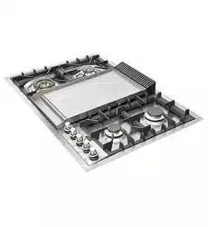
COOKING
HOBS
USER – Use and Maintenance
INSTALLER – Installation and maintenance
cod. EI33960080000EN
14/2022
ZONA PER TARGHETTA


INDEX
4 IMPORTANT SAFETY WARNINGS
11 INSTRUCTIONS FOR USE
11 Use of the cooking hob
13 Correct use of the fry-top
15 Correct use of the grills
18 Use of the gas fry-top
20 Use of the gas barbeque (optional)
21 CLEANING AND MAINTENANCE
21 Cleaning the appliance
22 Total black burners
23 INSTALLATION
23 Instructions
24 Built-in installation
25 Built-in tops’ hole size
28 Electric connection
29 Gas connection and transformation
31 Adjustment and/or adapting to different types of gas
32 Gas regulation
33 Gas jets adjustment table
34 Replacement of the injectors
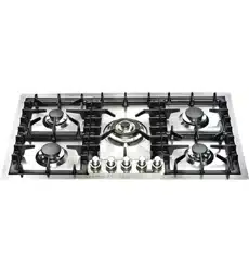
35 Cooking hob table
39 Adjustment of minimum
40 WIRING DIAGRAMS
40 Keys
42 TROUBLESHOOTING
39 Troubleshooting Guide
43 NOTES
4
The data plate, as well as being on the cover, is also on
the a pliance.
These warnings refer to different appliance models.
Be sure that you have correctly identified the model that
you possess (see the data plate).
These warnings are valid for the countries listed on the
plate.
Read the instructions booklet carefully, before using the
appliance. This contains very important
informations concerning safety during installation, use
and maintenance. The instructions booklet must be kept
with care for later consultation and for the identification
of the serial number.
The electrical safety of this appliance is only
guaranteed if it is properly earthed as required by the
regulations in force. It is fundamental to ensure that the-
se regulations have been respected; if you are in doubt,
call a skilled technician to have the electrical system
checked in detail. The
manufacturer does not accept any responsibility for da-
mage caused by a bad earthing system.
Before connecting the cooker, check that the
technical features on the data plate correspond per-
fectly with those of the electric system and of the gas
mains. The installation / regulation must be made by
qualified staff.
IMPORTANT
SAFETY WARNINGS
Appliances’ data
CAUTION
1
2
3
5
USER
IMPORTANT
SAFETY WARNINGS
Check that air circulates freely around the
appliance. This appliance is not connected to a com-
bustion products evacuation device therefore the pre-
mises’ ventilation system must be considered carefully
and according to the rules in force.
When using gas appliances, heat and dampness are
generated inside the premises.
Good ventilation of the kitchen is required by:
keeping the natural vents open or installing a
mechanical ventilator (hood). Intensive and
prolonged use of the appliance can make
supplementary ventilation necessary: opening a window
or increasing the power of the hood.
The power cable is supplied without a plug.
To connect please refer to the “electric connection” pa-
ragraph. We advise not using adapters, multiple sockets
or extensions.
Disconnect the power supply when the appliance is not
used for some time, switch off the mains and turn off the
gas.
When the electric cable is damaged, it must be
replaced by calling an after saves service approved by
the manufacturer.
The appliance must only be used for the purposes for
which it was intended (cooking). Any other use (for exam-
ple, heating a room) is incorrect and
therefore dangerous. The manufacturer declines all re-
sponsibility for damage caused by similar
incorrect uses.
4
5
6
7
8
9

6
The unit is not intended to be operated by an
external timer or a separate remote control system.
The use of any electrical appliance requires that the fol-
lowing rules are respected:
A. never touch the appliance when you have wet or damp
hands or feet;
B. never use the appliance in your bare feet;
C. avoid using extensions or, if this is inevitable, take all pos-
sible precautions;
D. Never pull on the electric cable to remove it from the
power socket;
E. do not expose the appliance to weathering (rain, sun,
etc.);
F. Be careful: the accessible parts may become very
hot during use. Keep children less than 8 years old
away from the cooker, if not continuously
supervised. This appliance can be used by
children from 8 years old and by persons with
reduced physical, sensory or mental abilities otherwi-
se with lack of experience and knowledge if they are
adequately supervised or if they have been instructed
on the safe use of the cooker and if they realise the
relevant dangers. Children
must not play with the cooker. Cleaning and
maintenance must not be done by unsupervised chil-
dren.
BE CAREFUL: some accessible parts may have high tem-
peratures during use: keep children at a
distance.
Before cleaning the appliance or carrying out
maintenance, disconnect the power supply by
removing the plug from the socket or switching the cur-
rent off through the switch provided.
10
11
12
13
IMPORTANT
SAFETY WARNINGS
7
USER
In the event of faults or malfunctions, switch off the ap-
pliance, turn off the gas tap and do not attempt to make
any repairs; these must be carried out
exclusively by an approved service centre. Always insist
on original spare parts. Failure to follow these indications
may endanger the safety of the cooker.
Never place unsteady or deformed pans on the
burners or on the electric hotplates as they could over-
turn accidentally.
When the appliance is not in use, ensure that all the
knobs are in the “●”/“○”/OFF position.
Never leave the hotplate switched on without a pan on
it, otherwise it will reach a very high
temperature quickly and the cooker or furniture in the
vicinity could be damaged.
Some parts of the cooker, especially the electric hotpla-
tes, stay warm for a long time after use. Be
careful not to touch them.
Do not keep below the cooker and do not use
inflammable liquids (detergents, sprays, alcohol,
petrol ...) near the cooker when it is switched on.
If using small electric appliances near the hob, be sure
to prevent the electric cable from touching the applian-
ce’s hot parts.
In order to work properly, gas cookers must be
installed in well ventilated premises. Ensure that
installation is carried out according to the
indications given in the “Installation” chapter.
14
15
16
17
18
19
20
21
IMPORTANT
SAFETY WARNINGS
8
The materials used in the construction of our
electrical appliance are compatible with the
environment and therefore recyclable. Packaging
remains should not be left within the reach of
children, but disposed of using specific recycling chan-
nels. The possibility of disposing of your
equipment through your local retailer and/or town coun-
cil should be investigated; remember to make your ap-
pliance unusable before scrapping it.
In case the tap is hard or precarious to turn, do not in-
tervene on the tap but shut off the gas and have the
authorised service centre intervene.
Do not modify or change the cooker.
Be careful: leaving the unguarded cooker with objects,
fats and oils can be dangerous and can cause a fire.
The cooker must be used by responsible people. Be ca-
reful: the use of inappropriate or unsuitable
protections can cause fires and / or damage.
Be careful: cooking with fat or oil can be dangerous or
cause fires.
Be careful: fire danger: do not keep objects on
cooking surfaces.
Be careful: in the case of fire never attempt to
extinguish a flame / fire with water, but turn the
appliance off and cover the flame with a lid or with a
fireproof cover.
22
23
24
25
26
27
28
29
IMPORTANT
SAFETY WARNINGS
9
USER
Be careful: metal objects such as knives, forks,
spoons or lids should not be placed on the cooker be-
cause they can get hot.
Be careful: do not use gas burners if the flame is
unstable.
Ensure that the flame diffusers are properly
positioned in their seats with their respective caps.
Do not leave the cooker unguarded during any
cooking that can spit fats or oils.
Do not touch the appliance’s heating elements when
on. Let them cool before proceeding with any cleaning.
Food preparation in plastic or aluminium containers on
hot cooking zones is forbidden just like the
positioning on the cooking surfaces of plastic or
aluminium foil objects.
Do not cover the burners or the hob with tinfoil.
Do not use the appliance’s surface as a work top, sharp
objects might scratch it.
Containers or grills must be positioned within the hob’s
perimeter.
Be careful: do not use frying pans, saucepans, grills or
stones for grilling of a greater size than the maximum
ones indicated for each single burner; above all they
must not cover more than one burner at the same time.
The heat accumulation might damage the cooker.
30
31
32
33
34
35
36
37
38
39
IMPORTANT
SAFETY WARNINGS

10
In case of liquid spilling over, remove it from the hob.
Do not place empty saucepans on the cooking areas.
40
41
IMPORTANT
SAFETY WARNINGS
11
USER
Keep children and the disabled away during operation. Do not use the
appliance as a heating source.
To keep the appliance efficient and safe, maintenance must be entrusted to s
pecialised technicians or to the after-sales service staff. Choose covered pans based on
the quantity of food to cook.
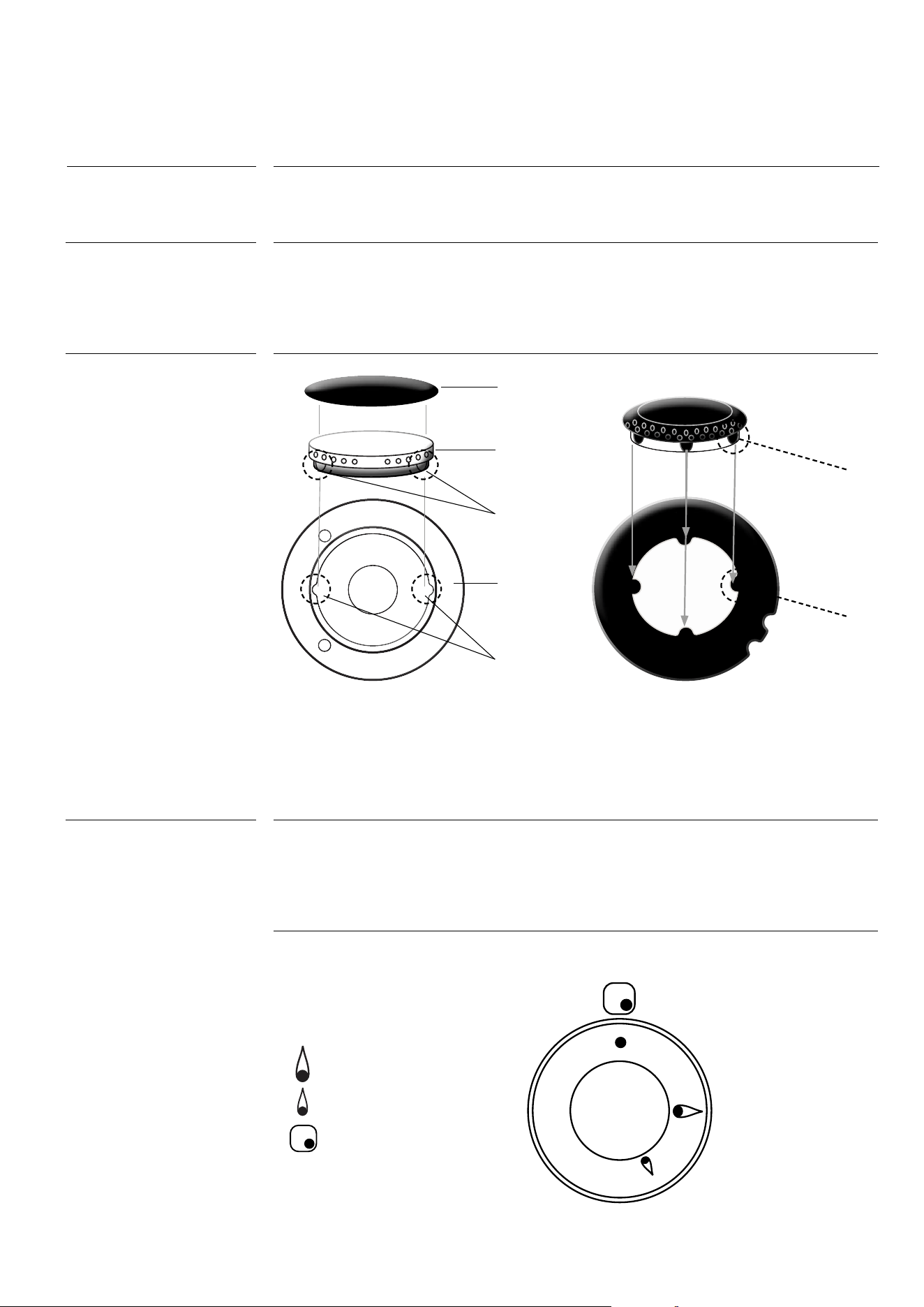
The index above the knobs fig.12a will help you to find the corresponding burner. Press
the knob by turning it anticlockwise and bring it to the ignition position; keep the knob
pressed for about 5 seconds so that upon its release the flame remains alight (in case of
unsuccessful ignition repeat the operation).
Symbols Function
Off
Maximum
Minimum
Index
INSTRUCTIONS FOR USE
Use of the cooking hob
WARNING
General notes
IMPORTANT
Lighting the burners
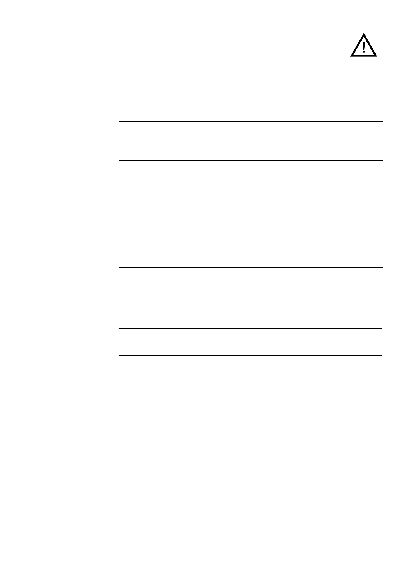
Position the brass flame distributor “d” (fig.
C) properly.
For this, line up the tooth “e” on the flame
distributor with thw hollow “b” of the alumi-
nium cup “a”.
Position the brass flamee distributor “b”
properly.
For this, line up the tooth “c” on the
flame distributor with the hollow “d” of
the aluminium cup “a”.
●
●
●
a
c
d
e
b
b
a
b
c
d
12
INSTRUCTIONS FOR USE
Use of the cooking hob
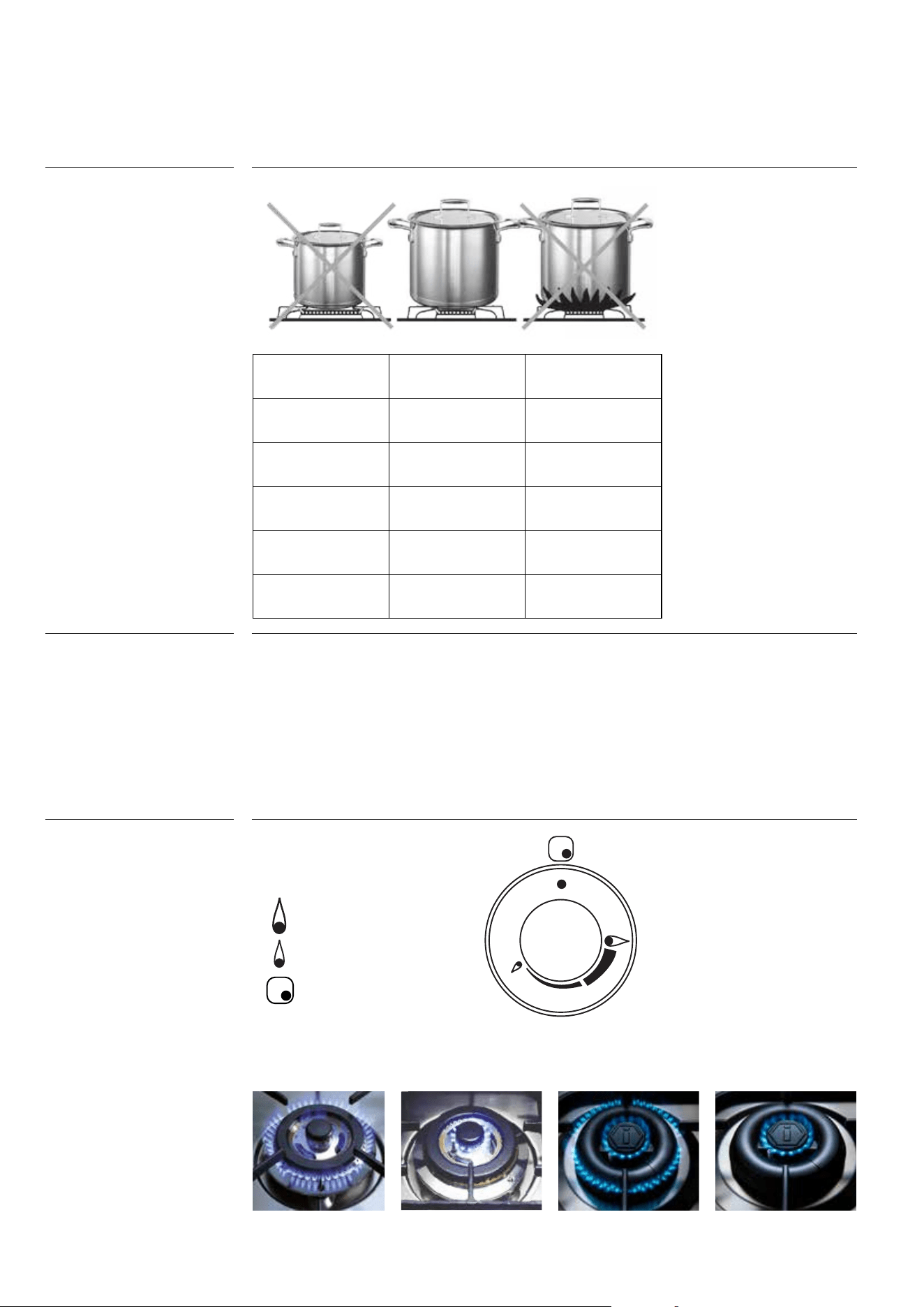
Pots to be used
according to the
size of the burners
Igniting the Triple ring
burner “DUAL”
Dual knob
Identify the knob with the help of the index placed at the knobs themselves. Press and
turn the knob to the (maximum) symbol for 5 seconds. Once the burner is on, continuing
to turn the knob anticlockwise leads to a first block of the knob that corresponds to the
medium. Applying a slight force the first block is
exceeded and the outer crown turns off leaving only the small central burner
called AUXILIARY. To adjust the auxiliary burner to minimum, turn the knob
anticlockwise until it stops. At this point, to turn the burner back on, turn the knob clockwi-
se to the desired value.
Symbols Function
Off
Maximum
Minimum
Index
Burners ID
Diameter Ø
(cm)
Medium SR 10/20
Large R 20/24
Fish burner P oven pans
Ring TC/DCC 22/28
Dual ring DUAL 24/30
●
●
●
●
●
13
USER
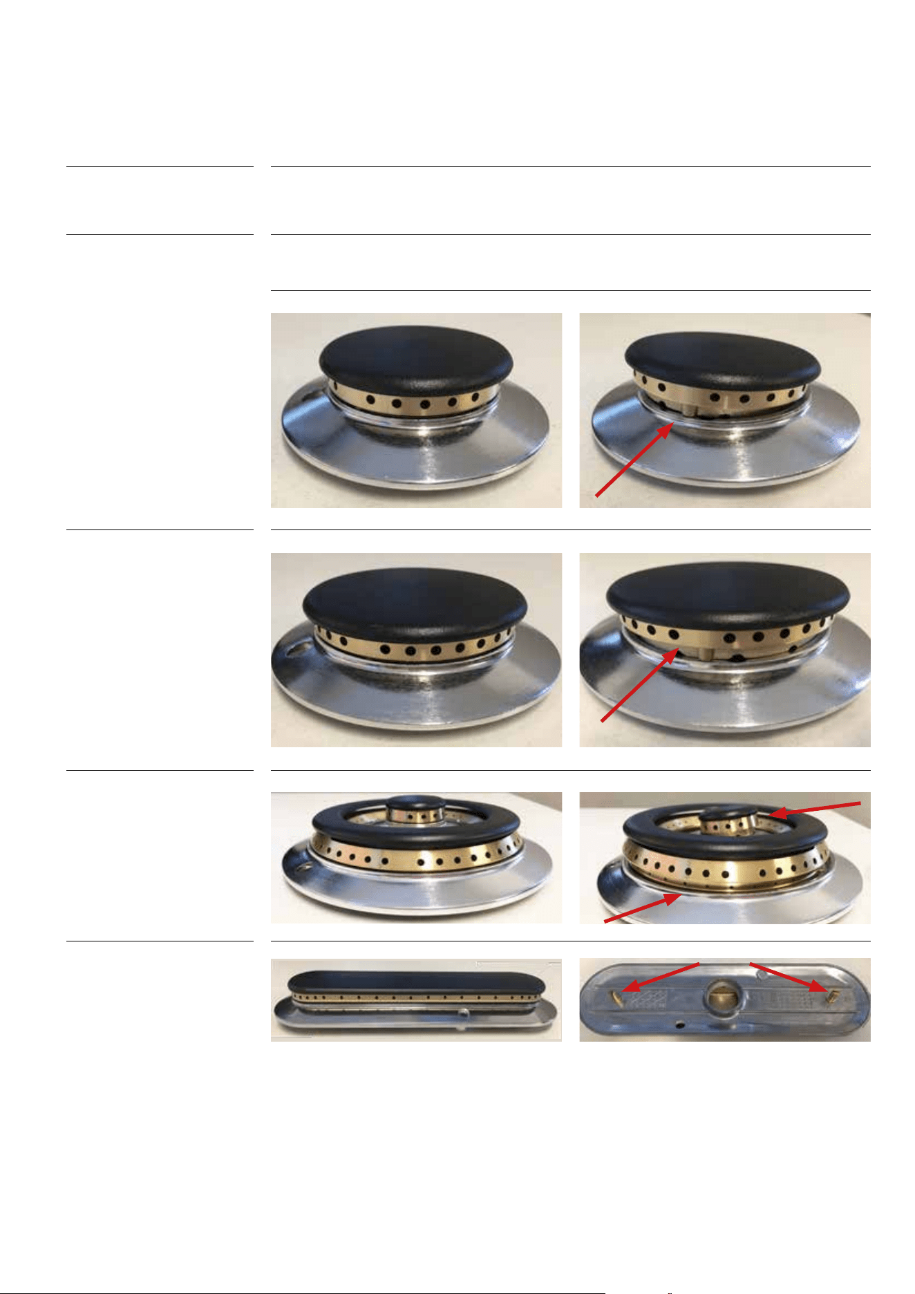
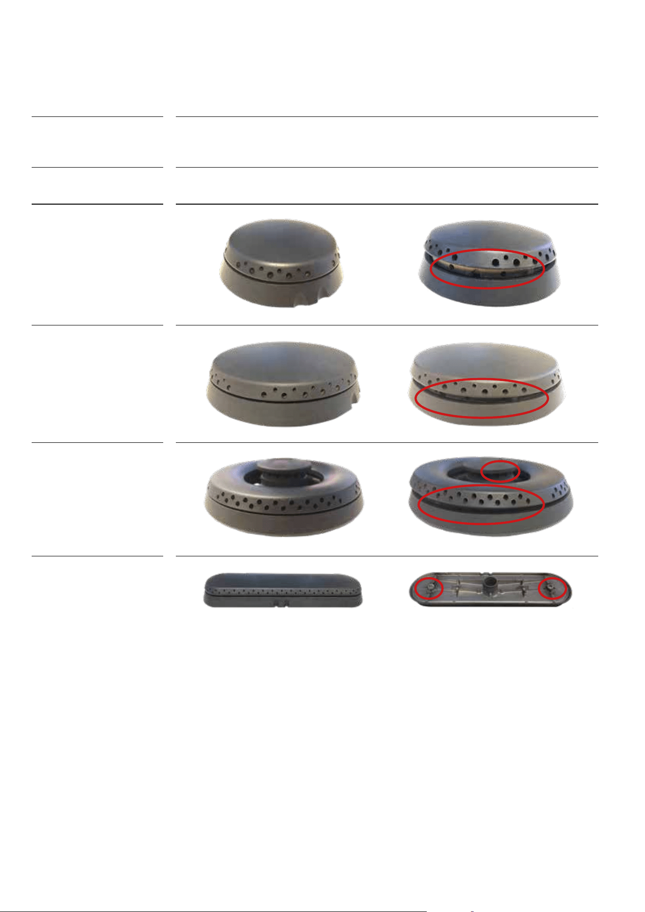
BE CAREFUL: always check that the burners are correctly positioned, thus having a homo-
geneous and not noisy flame.
Always check that the screws below the burner are fixed.
INSTRUCTIONS FOR USE
Correct use of burners
Placement of the
burners
Burners
Medium
Large
Dual ring
Fish burner
Right Wrong
14
BE CAREFUL: always check that the burners are correctly positioned, thus having a homo-
geneous and not noisy flame.
Always check that the screws below the burner are fixed.
INSTRUCTIONS FOR USE
Correct use of burners
Positioning of the
burners
Burners
Medium
Large
Dual ring
Fish burner
Right Wrong
15
USER
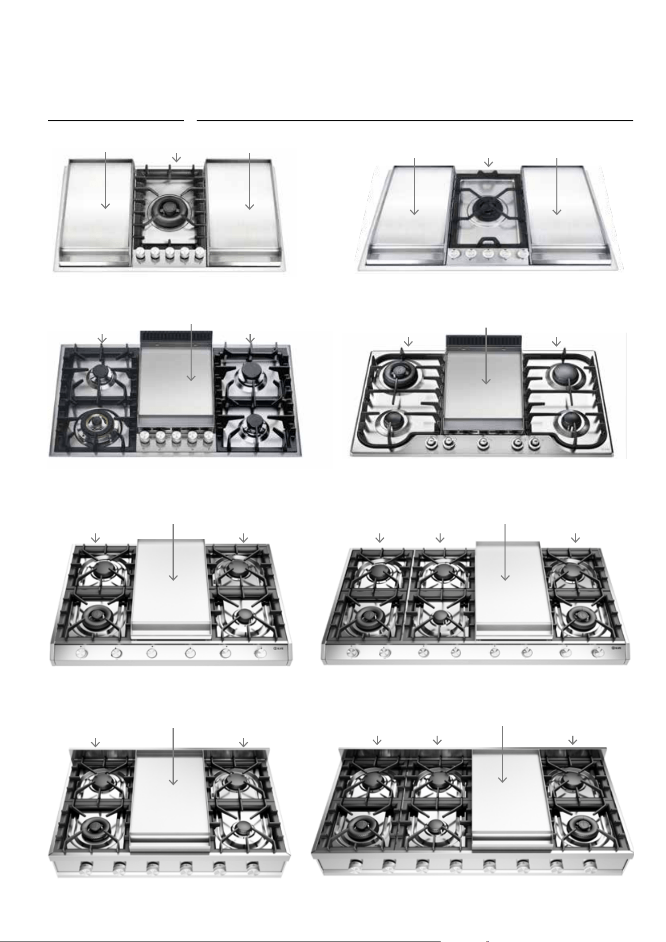
INSTRUCTIONS FOR USE
Correct use of the fry-top
HCB90F
HCPM95F
HCP1265F
HCP120F
OK OK
NO
OKOK
NO
HCP95F
HP95F
OK
NO NO
HCP9656F
HCP906F
OK
NO NO
OK
OK
OK
NO
NO
NO NONO
NO
NO
OK
NO NO NO
16
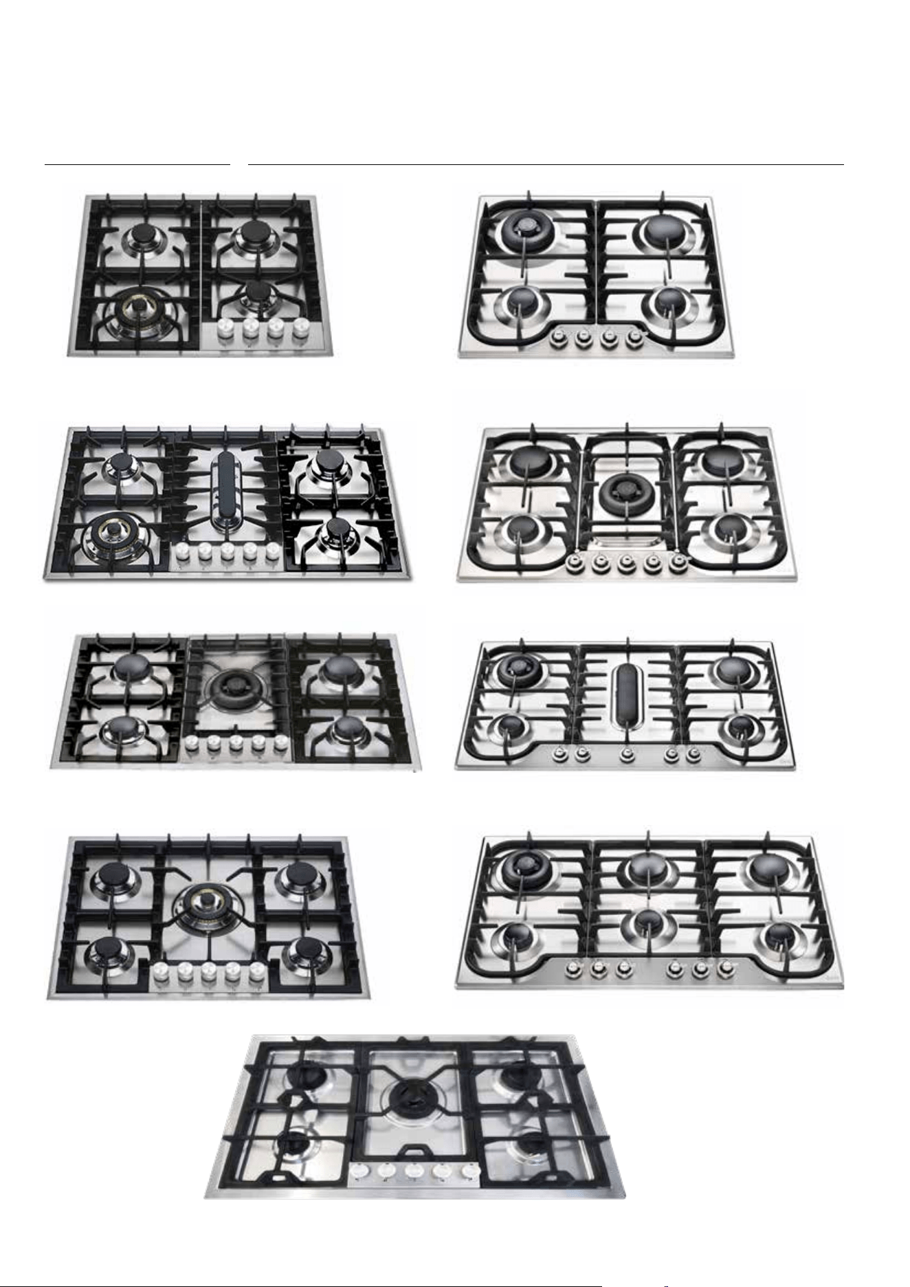
INSTRUCTIONS FOR USE
Correct use of the grills
HCPM95
HP65
HCP95
HCB906
HP75
HCB90P
HP95P
HCB60
HCB70
17
USER
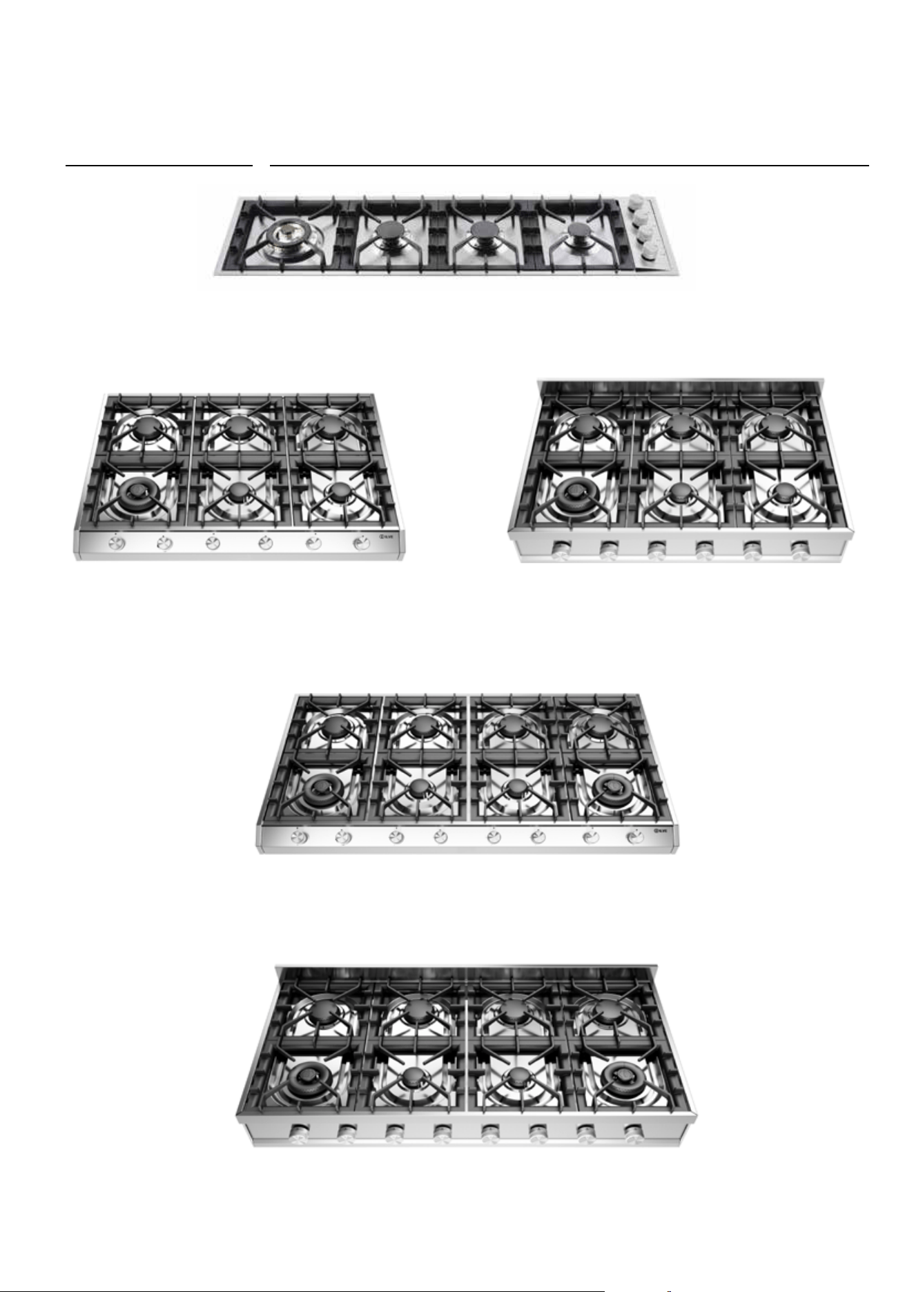
INSTRUCTIONS FOR USE
Correct use of the grills
HP1230
HCP1265
HCP120
HCP965
HCP906
18
INSTRUCTIONS FOR USE
Use of the gas fry-top
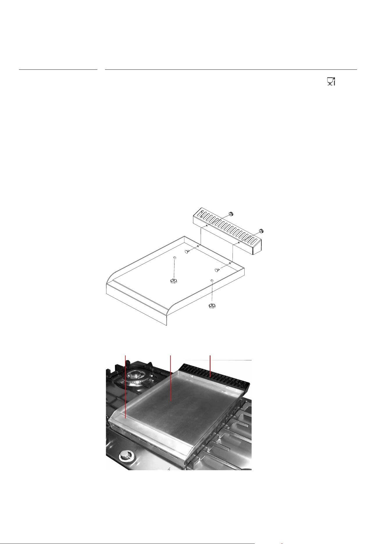
Instructions
The fry top consists of a stainless steel plate, suitable for contact with food [
] with a
uniform temperature of the cooking surface and with a very low heat dispersion.
To use the appliance, light the flame underneath the plate by turning the
corresponding knob (see “Burner ignition”) and make sure the flame is present.
Position the knob at the maximum for about 10 minutes and wait for the plate to heat up.
After this period of time, the plate is ready to start cooking.
By adjusting the flame, you will have no limit to your culinary imagination.
The position of the knob on the minimum allows slow or dietetic cooking while, for cooking
meat, fish and vegetables, faster cooking is indicated. The fry top plate is also suitable for
oriental dishes with an optional (lid) necessary for this type of cooking.
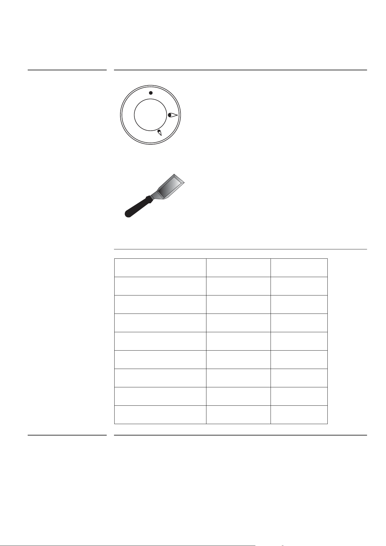
Some models are supplied with a spatula that will help you cooking and cleaning the
plate.
AB C
A = cooking area
B = drip tray
C = exhaust flue for
combustion flame
19
USER
Cleaning and care of the
Fry-Top
Pic. 2
INSTRUCTIONS FOR USE
Use of the gas fry-top
It is recommended to clean the plate thoroughly at the end of each coking
session. With the plate hot and the flame at minimum, remove the cooking
residue using the scraper provided (pic. 2). Pour a little water onto the plate and, still using
the scraper, continue cleaning the plate. Once the water has
completely evaporated, repeat the same operation even several times until the desired
result is obtained. It is extremely important to clean the plate when it is quite hot.
The black enamel flue may be cleaned with a soft cloth soaked with a solution of
lukewarm water and ammonia. Rinse and dry after cleaning.
Pic. 1
A
B
C
A = Max
B = Med
C = Min
Dish Knob posit. (pic.1) Time min.
Eggs B 2
Sliced aubergines
(0.5 cm thick)
B 9/13
Sliced potatoes B 5/7
Sliced courgettes B 3/5
Fish (sea bream weighing
about 200 g)
B 15
Hamburgher B 10
Beefsteak B 3
Porterhouse (2 cm thick) A 5
20
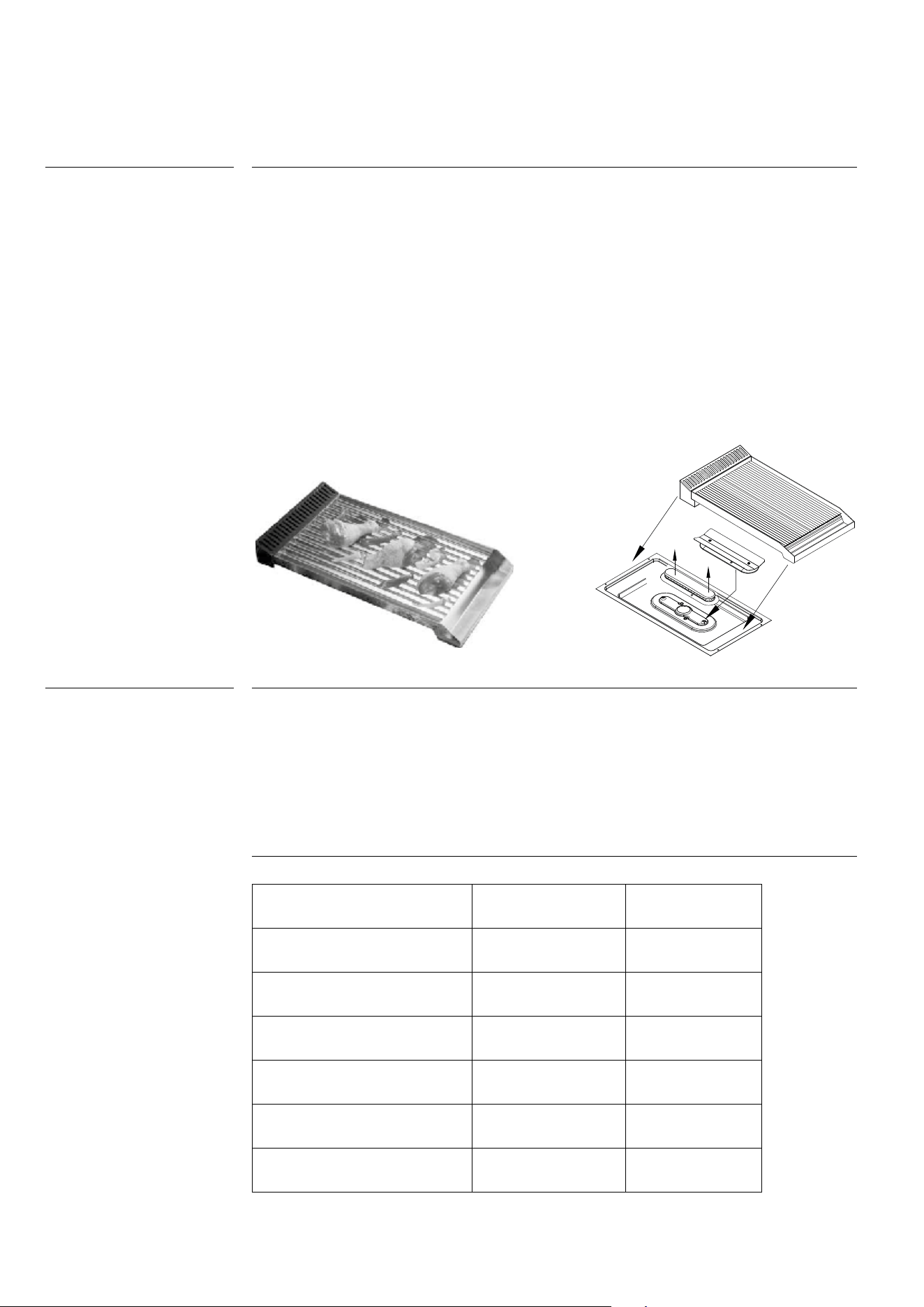
Replace the flame spreader A with the flame spreader protected for barbecue B. Before
refitting the barbecue plate, make sure you have positioned the flame spreader correct-
ly and carry out an ignition test.
To use the appliance, light the flame underneath the plate by turning the
corresponding knob (see “Burner ignition”) and make sure the flame is present. Position
the knob at the maximum for about 10 minutes and wait for the plate to heat up. After
this period of time, the plate is ready to start cooking. Place the burner at minimum and
place the dishes on the plate. Consult the cooking table for general information on
timing. You may find cooking times different from those shown in the table. This is com-
pletely normal, as times change according to the quantity and temperature of the food,
the type of gas and, of course, your
personal taste.
Allow the barbecue to cool before cleaning. Use a slightly abrasive sponge or a brush
with brass bristles following the satin finish of the plate. It is important to remove the incru-
stations that form between one lamella and the other. It is
advisable to clean the plate after each cooking. Like all barbecues, the plate with use
loses its brilliance and can create dark halos. Once cooled, the fireplace is cleaned with
a soft cloth soaked in a solution of warm water and ammonia.
Instructions
Barbeque cleaning
B
A
INSTRUCTIONS FOR USE
Use of the gas barbeque (optional)
Dish Knob posit. (pic.1) Time min.
Sliced aubergines
(0.5 cm thick)
B 3/15
Sliced potatoes B 5/7
Sliced courgettes B 4/6
Fish (sea bream weighing
about 200 g.)
A 10
Hamburgher A 10
Beefsteak B 3
21
USER
Before carrying out any cleaning operation, disconnect the appliance from the power
supply and close the general gas cock to the appliance.Cleaning the worktop: clean
the hob only after cooling. Periodically the burner cups, the
enamelled grills, the enameled lids, and the flame spreader must be cleaned with
lukewarm soapy water, rinsed and dried well. Any liquid overflowing from the pans must
always be removed with a rag. Cleaning the enamelled parts:
To maintain the characteristics of the enamelled parts, it is necessary to clean them fre-
quently with soapy water. Never use abrasive powders or metal pads. Avoid leaving acid
or alkaline substances (vinegar, lemon juice, salt, tomato juice, etc.) on the enamelled
parts and wash when the enamelled parts are still hot.
Clean the parts with warm water and non-corrosive liquid detergent and then dry them
with a soft cloth or microfibre. The brilliance is maintained by periodic
cleaning with special products normally available on the market. Never use
abrasive powders.
Absolutely avoid using steel sponges and sharp scrapers to avoid damaging the surfa-
ces.
Use normal, non-abrasive products, possibly with the aid of wooden or plastic
tools. Rinse thoroughly and dry with a soft cloth or a microfibre cloth. Avoid leaving resi-
dues of sugary food (such as jam) inside the appliance as they could
damage the enamel in the appliance.
Remove the grids and clean them in warm water and a non-abrasive detergent. Care-
fully remove any encrustations. Dry them and place them on the hob.
The continuous contact of the grids with the flame can cause an alteration of the ena-
mel in the vicinity of the areas exposed to heat. This is a completely natural phenome-
non that does not affect the functionality of this component at all.
For good operation, the ignition plugs and thermocouples must always be well cleaned.
Check them frequently and if necessary clean them with a damp cloth. Any dry residues
must be removed with a wooden toothpick or a needle.
The flame-spreader crowns and the lids are removable for easy cleaning. Wash them in
hot water and non-abrasive detergent.
Carefully remove any encrustations and wait until they are perfectly dry.
In the event of a malfunction, make sure that the holes in the outer crown are always
perfectly clean.
The use of the dishwasher for cleaning grills, flame spreaders and lids is not
recommended
Warning
Cleaning of stainless steel
parts
Food stains or residues
Cooking hob grills
Igniters and
thermocouples
Flame distributor rings
and covers
CLEANING AND MAINTENANCE
Cleaning the appliance
22
In order to preserve the quality of the coating, some cleaning and washing methods are
recommended:
• Allow the product to cool to room temperature before cleaning. It is advisable not
to immerse it in cold water when it is still hot.
• Wash with warm water, and with a minimum of neutral detergent. Rub with a cloth,
preferably in natural cellulose, or a non-abrasive sponge.
• Do not use powders, iron wool, abrasive cloths or sponges.
• Do not let food burn on the burner. In the event of surface stains / stains may ap-
pear. These traces do not alter the functionality of the product, and in some cases
they can be eliminated with this procedure: immerse the product in hot water, with
detergent, rub gently with a cloth, preferably in natural cellulose, in any case do not
use cloths or abrasive sponges. For more resistant stains it is advisable to heat white
vinegar and rub as indicated above.
• Avoid leaving the burners in contact with food for a long time, especially if acids,
such as tomato sauce.
• Avoid contact with metal objects, if it is the case to use wooden or plastic objects.
• Avoid washing in the dishwasher, a part of the product is not coated and would be
irreparably damaged.
• In the event of a malfunction, make sure that the holes in the outer crown are always
perfectly clean.
Total black burners
coated with treatment
nanotechnology
CLEANING AND MAINTENANCE
Total black burners
23
INSTALLER
1
20 mm
2
Fig. A
This appliance complies with the following directives
DIRECTIVE EU2002/96/EEC
LOW TENSION DIRECTIVE EEC 2014/35/EU
GAS DIRECTIVE 2009/142/EC
ELECTROMAGNETIC COMPATIBILITY DIRECTIVE 2014/30/EU
REGULATION No. 1935/2004 (contact with foods)
Installation must only be made by qualified personnel in the respect of
regulations for permanently ventilated premises according to UNI 7129 01/02/04 – 7131.
This appliance is type “A” and not to be joined to a combustion products’
expelling device but must be installed under a hood or another smoke extraction system
in compliance with the rules in force. The knowledge and consultation of the rules is cri-
tical for a qualified installer. As an indication, remember that the air necessary for burner
combustion is 2m3/h for each kW of nominal power
installed (see plate). If the appliance is used intensively and for a prolonged time, sup-
plementary ventilation may be necessary; in this case open a window or increase the
power of the mechanical extractor hood.
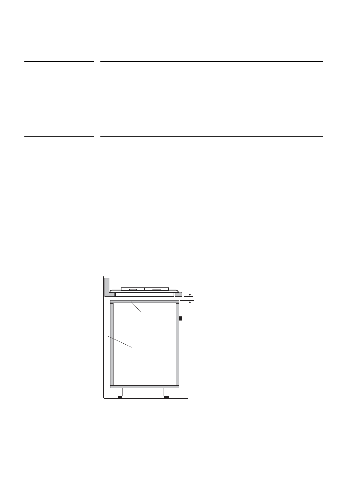
The unit must be made in such a way that the flames are not blown out if the doors are
opened or closed rapidly. The bottom of the cooking hob must not be subject to depres-
sion or pressure when the doors are opened or closed.
We advise working as shown in the figure (A). The panel under the hob must be easy to
remove for maintenance purposes.
Installation instructions
Ventilation of the
premises
Fitting the cooking hob
onto the base unit with
door
INSTALLATION
Instructions
24
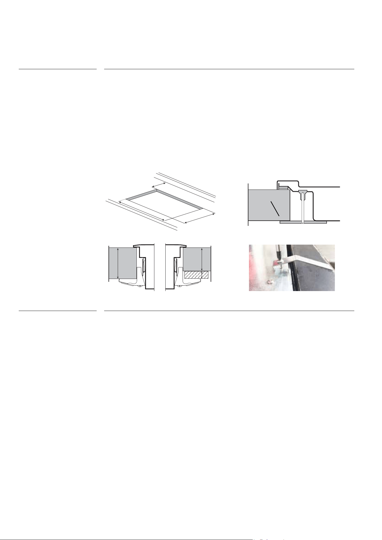
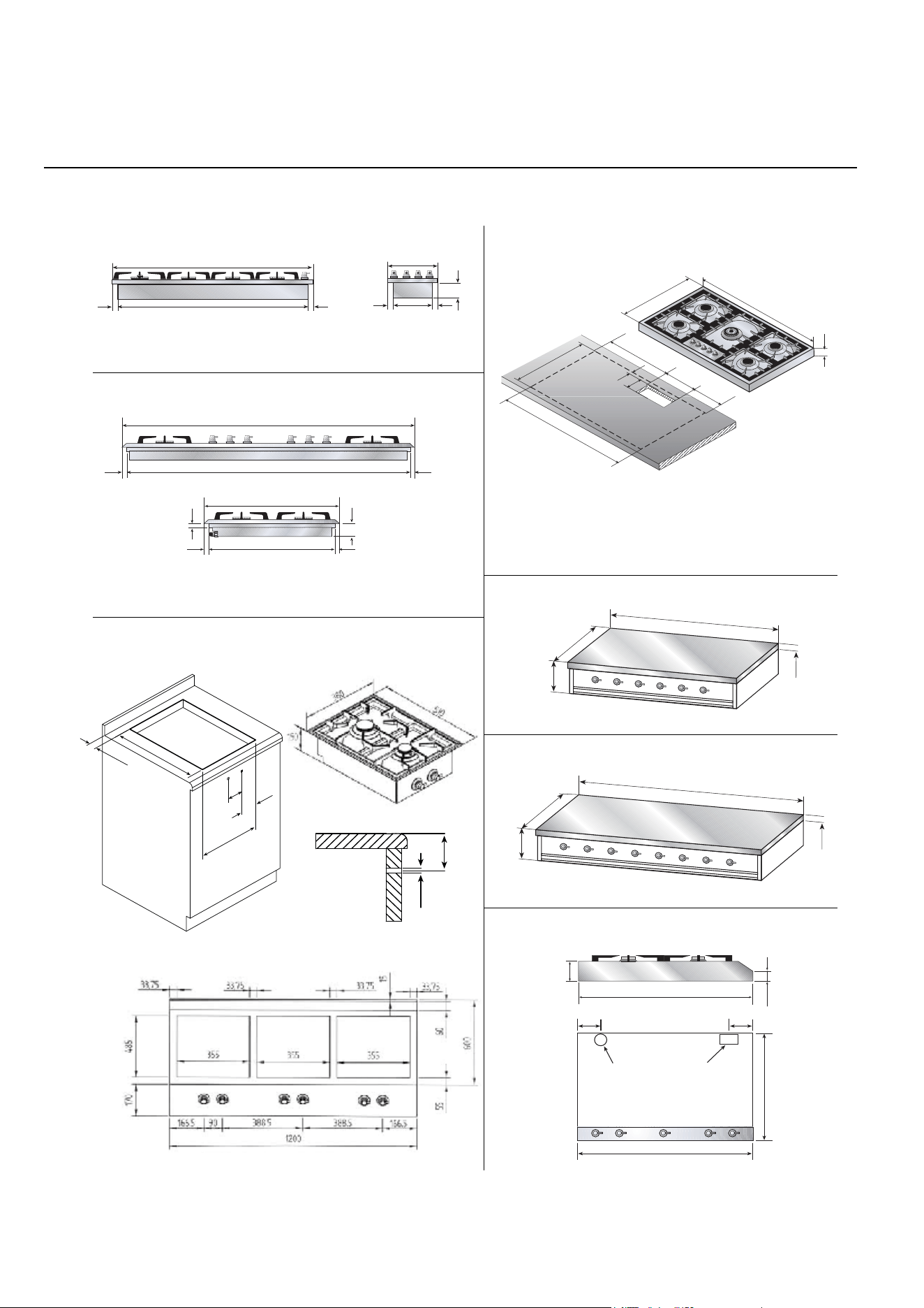
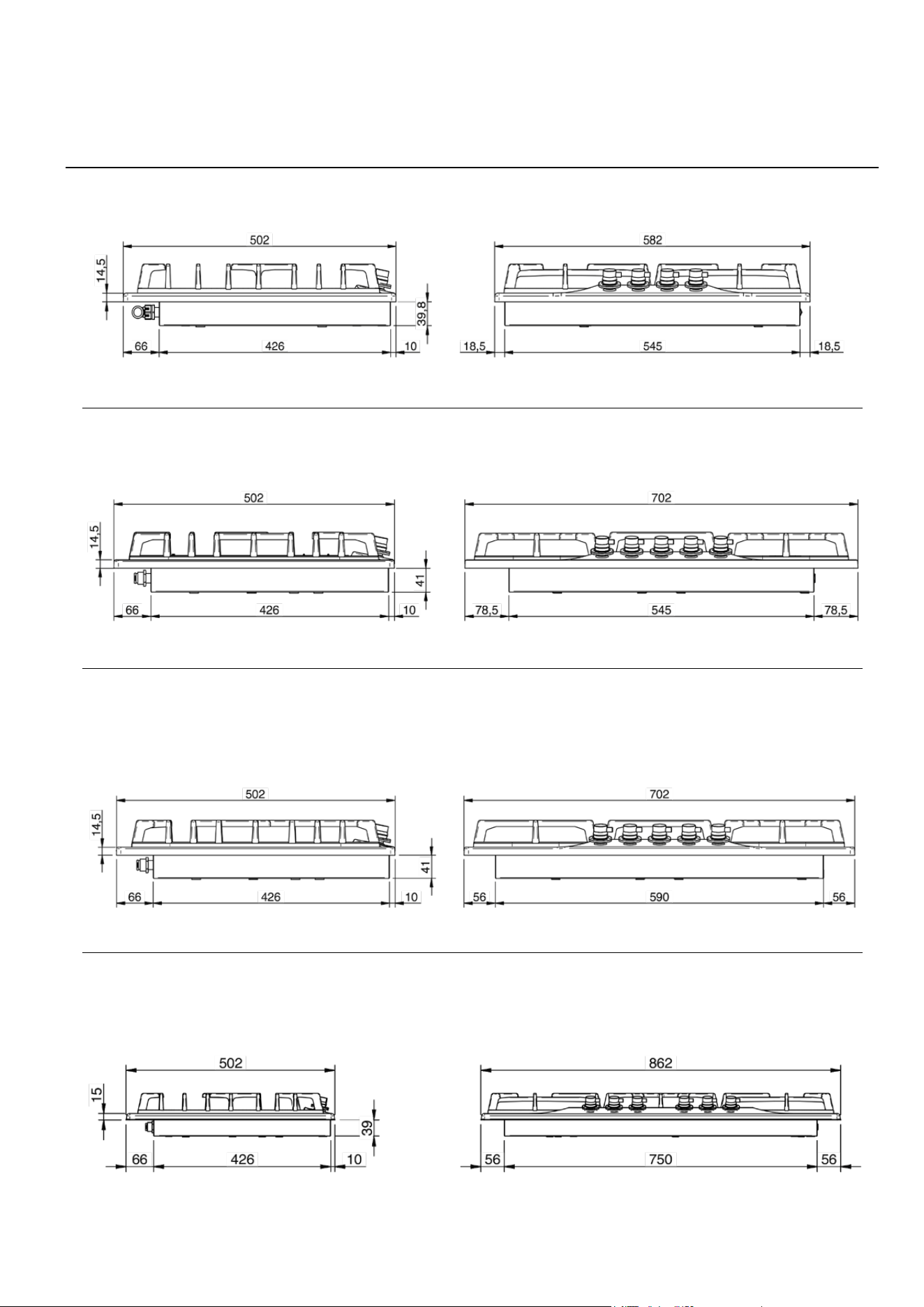
All the built-in tops are designed to be mounted on furniture with surfaces of any material
and with a thickness varying from 3 to 4 cm. To avoid excessive
overheating of the side and rear walls, it is recommended to drill the hole for the surface
recessed, at a minimum distance of 45-50 mm, respecting the
measurements shown in the table (pic. 1). To avoid infiltration of liquids under the wor-
ktops, it is essential to apply the appropriate healing (C), which is supplied with the top.
Fixing to the cabinet is done with the brackets that are supplied with the
appliance (pic 2a, 2b, 2c).
For counter tops (HP665, HP965, HP1265, HAP95, HAP125, HP90, HP120 ...), the s
upport surface must have the surface base equal to the appliance and a
strength such as to support a weight of at least 100 kg.
Our appliances can be fitted as:
• freestanding, Class 1
• fitted between units, Class 2/1
• built-in into units, Class 3
The minimum distances from the furniture must be:
• between top and overhead hood 650 mm
• between top and overhead cabinet 700 mm
• between top and back wall 50 mm
• between top and overhead side wall 50 mm
• between top and lower wall 20 mm
• the built-in top fitted onto a base unit with door must be installed according to pi-
cture A
• the cooking hobs for supported appliances must support a weight of at least 100 kg
• the furniture must resist at least up to 120°C
• the thickness of the top must be at least 3 cm
The built-in appliances must be inserted (see pic. 1), fixed (see pic. 2a, 2b) with the
brackets, applying the appropriate seal (C) between the furniture and the appliance.
The application of the hob in the furniture can also be done with an oven below paying
attention to the path of the power cable that must not come into contact with hot surfa-
ces (50 ° C beyond the environment).
Built-in installation
Built in the cooking top
INSTALLATION
Built-in installation
40 mm
30 mm
10
50
B
A
Fig. 1
Fig. 2b
(mod. HP65, HP75, HP95,HP125)
40 mm
30 mm
10
50
B
A
40 mm
30 mm
10
50
B
A
Fig. 2a
C
Fig. 2c
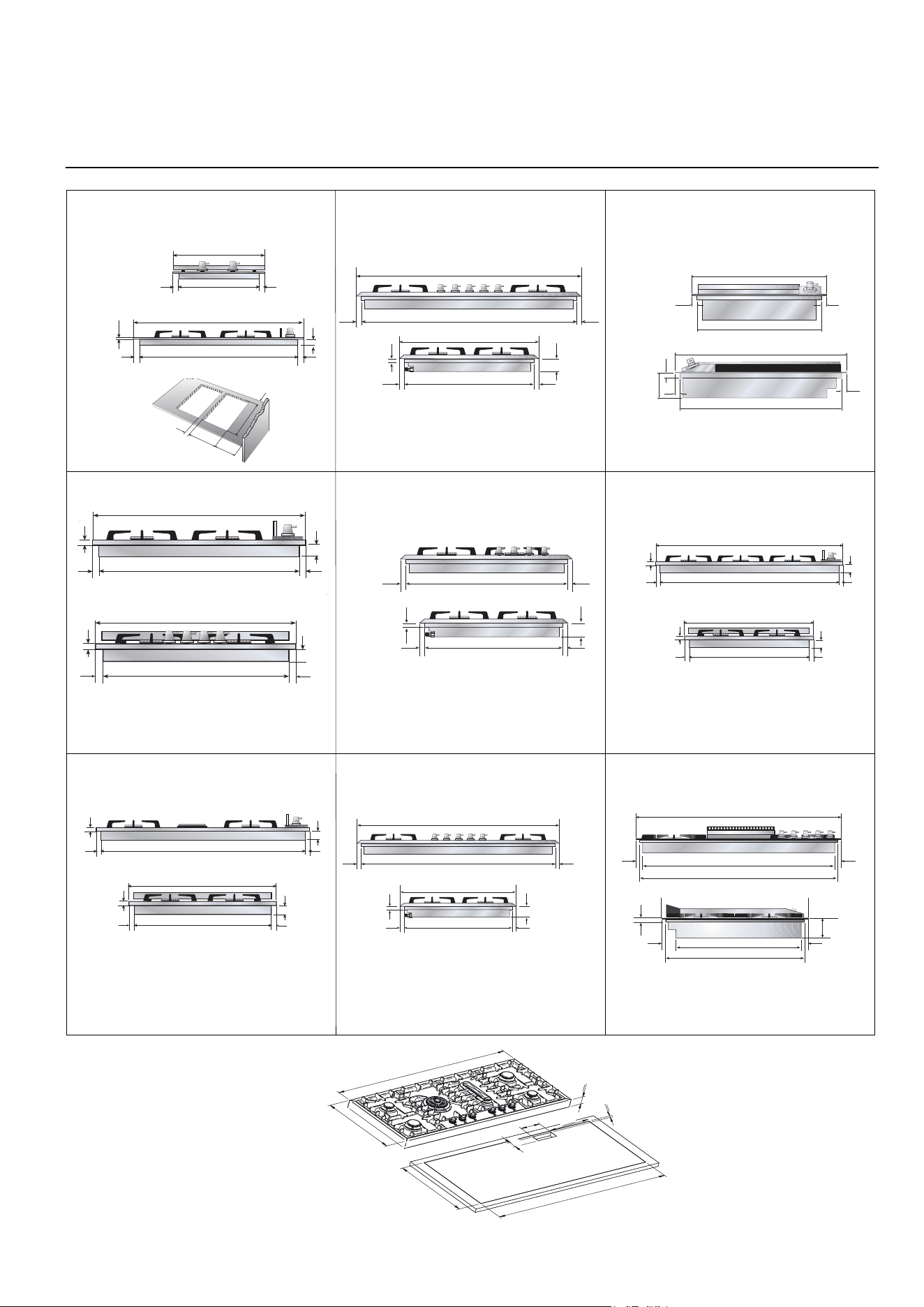
25
INSTALLER
INSTALLATION
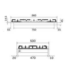
Built-in tops’ hole size
40
270
160
475
50
15
15
15
15
8
470
500
260
45
290
MOD. H30 - H30P - H30C
45
15
750
15
8
15
470
15
45
8
500
MOD. H38
MOD. HP45F
15
371
511
15
481
15
85
15
15
401
MOD. HP75
700
17 17
15
65
47617 17
666
510
556
15
65
476
17 17
17 17
MOD. HP65
15
470
15
45*
8
500
MOD. H36
15
830
15
45*
8
860
15
470
15
45*
8
500
MOD. H39
846
17 17
15
65
476
17 17
880
510
MOD. HP95 MOD. XLP90
568
16 16
16
85
514
870
15 15
900
841
65
1
3
0
5
0
5
2
0
1
1
7
1
1
1
7
1
5
2
0
1
5
2
8
0
15
550
15
45*
8
580
672x490 380x490
570x490 835x475 - *H90=50555x475 - *H60=50
860x490 875x580755x475
HCP95
HCPM95
MOD.HAP125
26
INSTALLATION
Built-in tops’ hole size
MOD. HP1230
1115 x 295
17 17
1110
1144
15 15
95
288
318
MOD. HP125
16
65
476
17 17
510
1128
17 17
1160
1140 x 490
06
520
890
130 x 50
520
890
20
50
550
130
210
MOD. HAP95
MOD. HF40
100
ø22
min. 40 mm
485
132,5
355
90
70
650
600 (P665) / 900 (P965) / 1200 (P1265)
65
Electrical
connection
Gas connection
G
E
MOD. HP665 - HP965 - HP1265
MOD. HP90 - HCP90
MOD. HP120 - HCP120
650
42,5
85
900
600
185
04
1200
600
581
04
HACP95
HACPM95
HCP665 - HCP965 - HCP1265
27
INSTALLER
MOD. HC60
MOD. HC70
MOD. HC70SD
MOD. HC90
Built-in tops’ hole size: 555 x 475
Built-in tops’ hole size: 555 x 475
Built-in tops’ hole size: 640 x 475
Built-in tops’ hole size: 835 x 475
INSTALLATION
Built-in tops’ hole size
28
The appliances are prepared for connection to the voltage shown on the data plate.
Before connecting the appliance to the mains check that:
• the electromagnetic switch or the socket are able to support the ap-
pliance’s load (see data plate);
• the power supply system must have an efficient earth.
The appliance is supplied with a cable but without a plug: the connection must be
made taking into account that the green-yellow cable is the earth conductor
and
it must never be interrupted.
For direct connection to the mains, it is necessary that:
• the relief valve and domestic system can support the equipment’s load (see data
plate)
• the power supply system must have an efficient earth
• the socket or omnipolar switch, with a minimum 3 mm contact opening, must be
easily reached once the appliance has been installed a mains shut-off must be
incorporated in accordance with installation rules.
The green-yellow earth cable must never be interrupted even by the switch. The
power cable must be routed in such a way that it does not come into contact with
surfaces that have a temperature greater than 50°C above room
temperature. If cable replacement is necessary contact the after-sales service.
* HP965B, HP1265B, HP90B, HP120B
INSTALLATION
Electric connection
Power (230V) (240V)
Hotplate (Ø 115) 550 W 600 W
Hotplate (Ø 115) 920W 1000 W
Hotplate (Ø 115) 1380 W 1500 W
Barbeque 1900 W 2070 W
Barbeque* 2650 W 2880 W
29
INSTALLER
(UNI CIG 7129/7131)
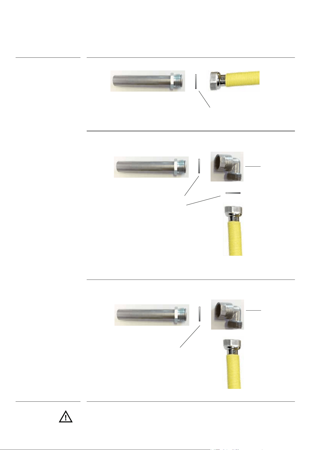
The appliances must be connected to the gas network with rigid or flexible metal pipes
(maximum length 2 meters) suitable for gas appliances. The connecting pipes and their
maximum lengths must meet current standards (UNI CIG 9891), be replaced before the
deadline (if specified on the pipe) and be connected to the appliance by means of
fittings:
A) Directly on the ISO R228 connection (seal with ISO R228 gasket), if the pipes allow it,
see figure 3
B.1) If the connection must be direct (right-left-down), the accessory must be inserted
(fig. 4a - fig. 4b).
B.2) Use the gasket (ISO R228) to seal between the tube and the ramp. 4a
B.3) The tapered fittings with the seal on the thread must be used for sealing on the thre-
ad (ISO R7) (fig. 4b)
B.4) To improve the seal, it is possible to use a mastic suitable for GAS.
When the gas is taken from a cylinder, the appliance must be powered with a pressure
regulator compliant with the UNI-CIG 7432 standard:
- with continuous flexible stainless steel wall pipes according to UNI-CIG 9891, with a ma-
ximum extension of 2 meters and sealing gaskets according to UNI 9264.
The gas taps fitted in your kitchen must work with liquid gas of controlled quality, supplied
at the proper nominal pressure. This pressure must be guaranteed by a special certified
pressure regulator. The use of gas coming from uncertified
sources and/or the improper use of the GPL cylinder as well as the relative
regulator, can invalidate the product’s guarantee. It is especially necessary to avoid all
the situations that could pollute the gas with residues and impurities that, when introdu-
ced into the gas circuit, can irreparably damage the control components such as taps
and thermostats. It is recommended to:
• use only GPL cylinders coming from official retailers and authorised by the various
manufacturers;
• use the cylinders until empty without inclining or overturning them;
• carry out regular cleaning of the filter at the pressure regulator inlet;
When the connection is made, it is recommended to check the connections’ seal
with special foams (NO FLAMES).
Periodically check the gas connection pipe’s good condition and replace it when there
are signs of anomalies.
Gas connection
Precautions for using the
product with gpl gas
WARNING
IMPORTANT
INSTALLATION
Gas connection and transformation
30
Pic. 3
Sealing ring
Any adjustment, maintenance, etc... must be made by an authorised
technician after having disconnected the appliance from the mains and shut off the
gas supply.
Sealing ring
Pic. 4a
Junction
Sealing ring
Pic. 4b
Junction
INSTALLATION
Gas connection and transformation
31
INSTALLER
The hobs are delivered to operate as indicated on the data plate. If a t
ransformation should be necessary, proceed as described in the next
paragraph.
Injector replacement and air adjustment for models:
H30 - H360 - H380 - H39 - HF40 - HP45F - HP65 - HP75 - HP95 - HAP95 - XLP90F- HP1230
HP125 - HAP125 - HP665 - HP965 - HP1265 - HP90 - HP120
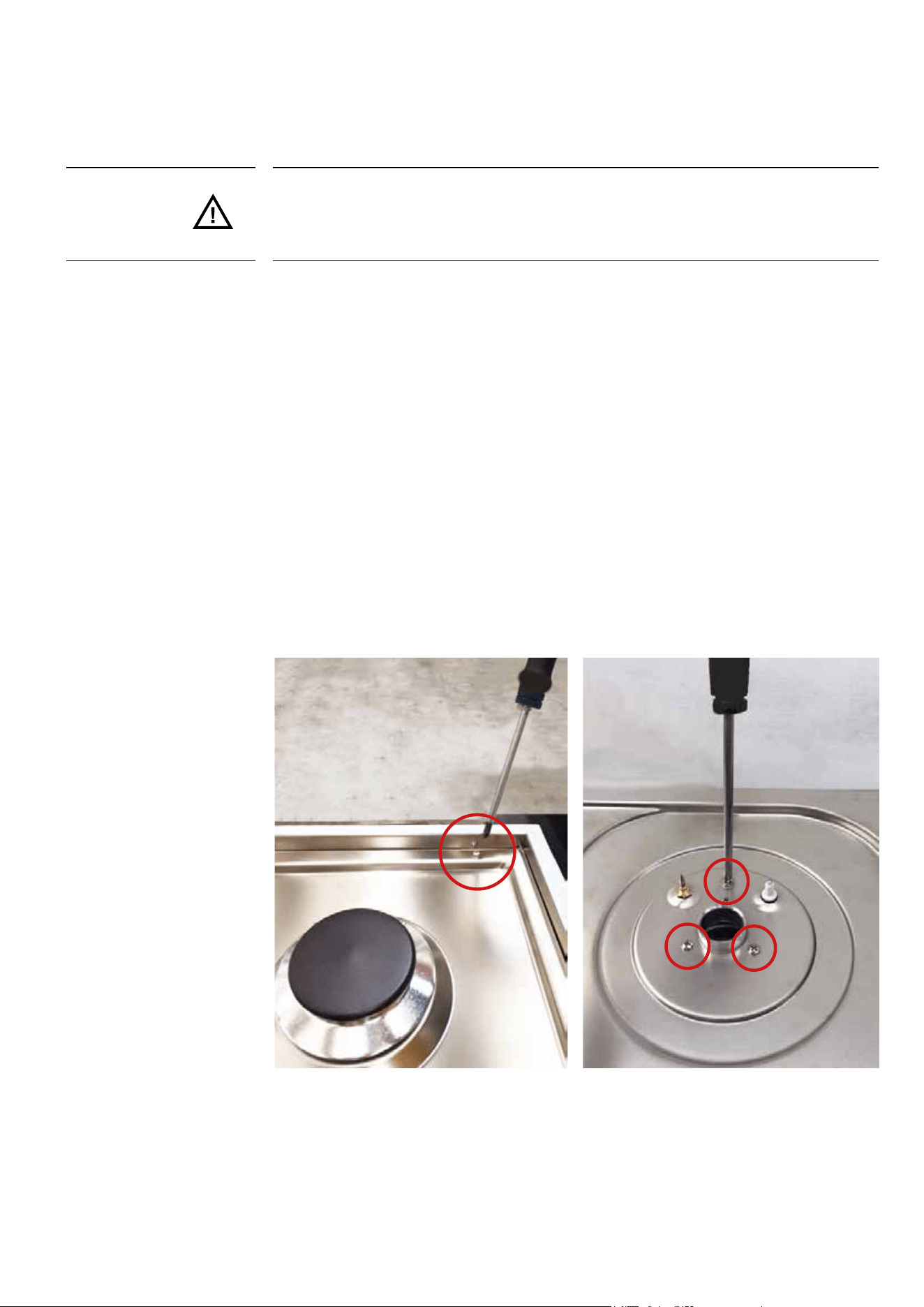
1. Remove the grill and the burners from the worktop.
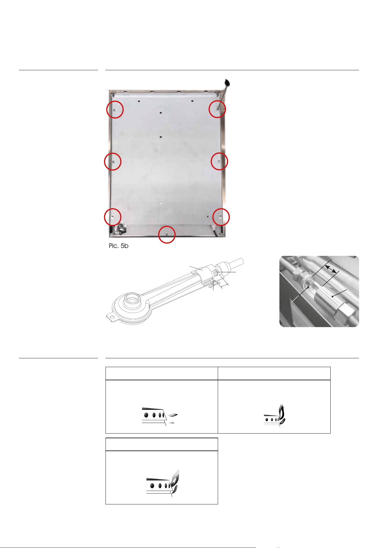
2. Unscrew the screws marked with the arrows that fix the worktop to allow it to be raised,
pic. 5, pic. 5a, pic. 5b.
3. Unscrew venture pipe screw “F” (pic. 6, pic. 7) and open completely the air regulator “R”.
4. Unscrew the injectors (U) and replace them with those suitable for the gas in use and
supplied with the appliance. Refer to table on page 33.
5. Air adjustment is made by the special regulator “R” based on the “X” values shown in
table on page 33, opening of primary air. When adjustment is over block the regu-
lator “R” with screw “F”.
Adjustment and/or adap-
ting to different types of
gas
Pic. 5
Pic. 5a
INSTALLATION
Adjustment and/or adapting to different types of gas
32
INSTALLATION
Gas regulation
A B
Flame with too much air:
small and drawn.
Decrease the“X” amount
UU
Flame with scant air:
Irregular with yellow points.
Increase the “X” amount.
UU
C
Correct flame:
Blue
UU
F
X
R
U
X
R
U
C
Pic. 6
Examples of air regulation
(for information)
Pic. 7
F
X
R
U
X
R
U
C
Pic. 5b
33
INSTALLER
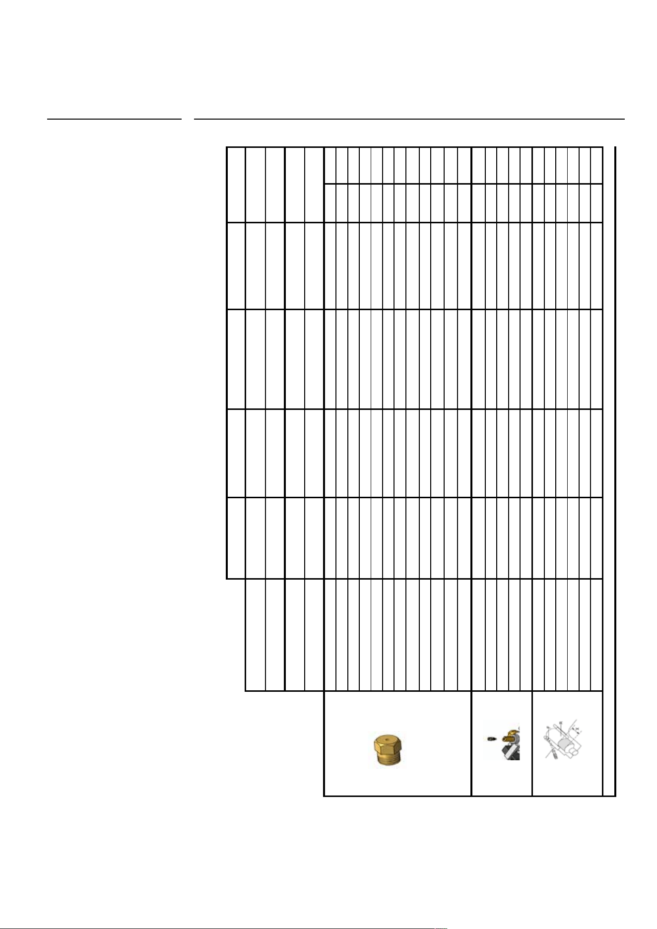
Gas jets adjustment table
INSTALLATION
Gas jets adjustment table
TABELLA UGELLI PIANO
SR R P C
Qmax kW 1,80 2,60 3,10
4,30 / 3,40
(3)
Qmax g/h 131 189 225 313
Qmin kW
0,40 / 0,51
(1)
/ 0,45
(2)
0,60 / 0,76
(1)
/ 0,66
(2)
1,20 / 1,57
(1)
/ 1,35
(2)
1,70 / 2,20
(1)
/ 1,90
(2)
Qmin g/h
29 / 37
(1)
/ 33
(2)
44 / 55
(1)
/ 48
(2)
87 / 114
(1)
/ 98
(2)
124 / 160
(1)
/ 138
(2)
G30/G31 28..30/37 mbar 0,62 0,78 0,82 1,00 0,35 0,92
G30/G31 50 mbar 0,55 0,68 0,75 0,90 0,33 0,82
G30 37 mbar 0,62 0,74 0,82 0,92 0,35 0,92
G20 20 mbar 0,97 1,17 1,30 1,50 0,55 1,40
G20 25 mbar 0,87 1,10 1,17 1,35 0,55 1,35
G25 20 mbar 1,05 1,30 1,45 1,65 0,62 1,60
G25 25 mbar 0,97 1,23 1,35 1,55 0,62 1,50
G2.350 13 mbar 1,35 1,65
1,85 / 1,80
(4)
2,20 0,78 2,20
G25.1 25 mbar 1,05 1,25 1,35 1,60 0,62 1,55
G110 8 mbar 1,90
2,45 / 2,30
(4)
3,00 / 2,60
(4)
3,30 1,10 3,20
G120 8 mbar 1,75
2,30 / 2,20
(4)
2,60 / 2,40
(4)
3,20 1,05 3,00
G150.1 8 mbar 1,85 2,40
3,20 / 2,80
(4)
3,30 / 3,20
(4)
1,10 3,30
G30/G31
0,30 / 0,32
(4)
0,38 / 0,40
(4)
0,50 / 0,52
(4)
0,61 / 0,64
(4)
0,27 0,60
G20 REG REG REG REG REG REG
G25 REG REG REG REG REG REG
G2.350 13 mbar REG REG REG REG REG REG
G110/G120 REG REG REG REG REG REG
G30/G31 2,00 6,00 20,00 20,00 20,00 20,00
G20 2,00 3,00 3,00 6,00 20,00 4,00
G25 2,00 3,00 3,00 4,00 20,00 4,00
G2.350 13 mbar 0,00 3,00 5,00 5,00 20,00 4,00
G110/G120 0,00 0,00 0,00 3,00 1,00 0,00
G150.1 8 mbar 0,00 0,00 0,00 3,00 1,00 10,00
(1)=DE AT (2)=PL (3)=G110/G120/G150.1
X= mm
0,37
27
Ø mm
by-pass Ø mm
DUAL
4,50 / 3,60
(3)
327
34
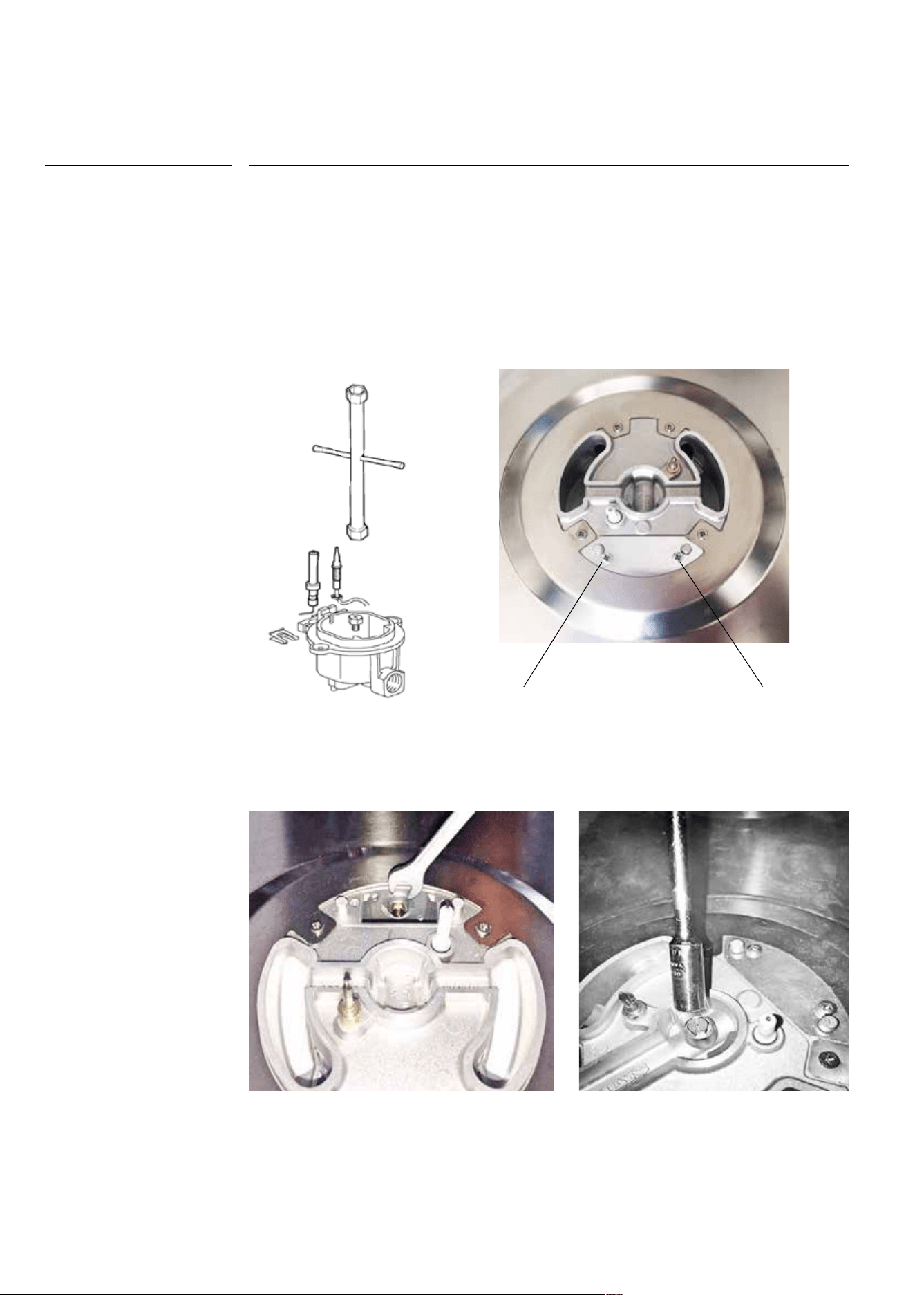
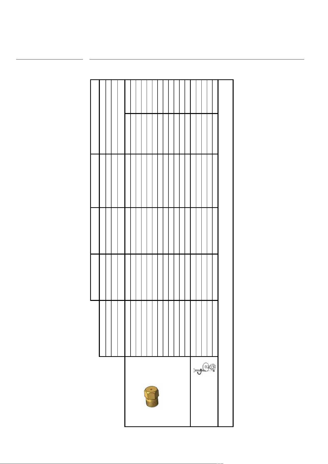
1. Remove the grill and the burners from the hob.
2. SR – R – P burners: unscrew injectors “U” using a 7-mm spanner (fig. 8) and replace them
with those for the new gas according to table on page 35.
3. DCC – Dual burners: unscrew the 2 screws “P” and remove cover “C” fig. 9. unscrew
injectors “U” using a 7-mm spanner (fig. 10, fig.11) and replace them with those for
the new gas according to table on page 35.
HC60 – HC70 – HC90
Pic. 8
Pic 10
Pic. 9
C
P
P
Pic. 11
INSTALLATION
Replacement of the injectors
35
INSTALLER
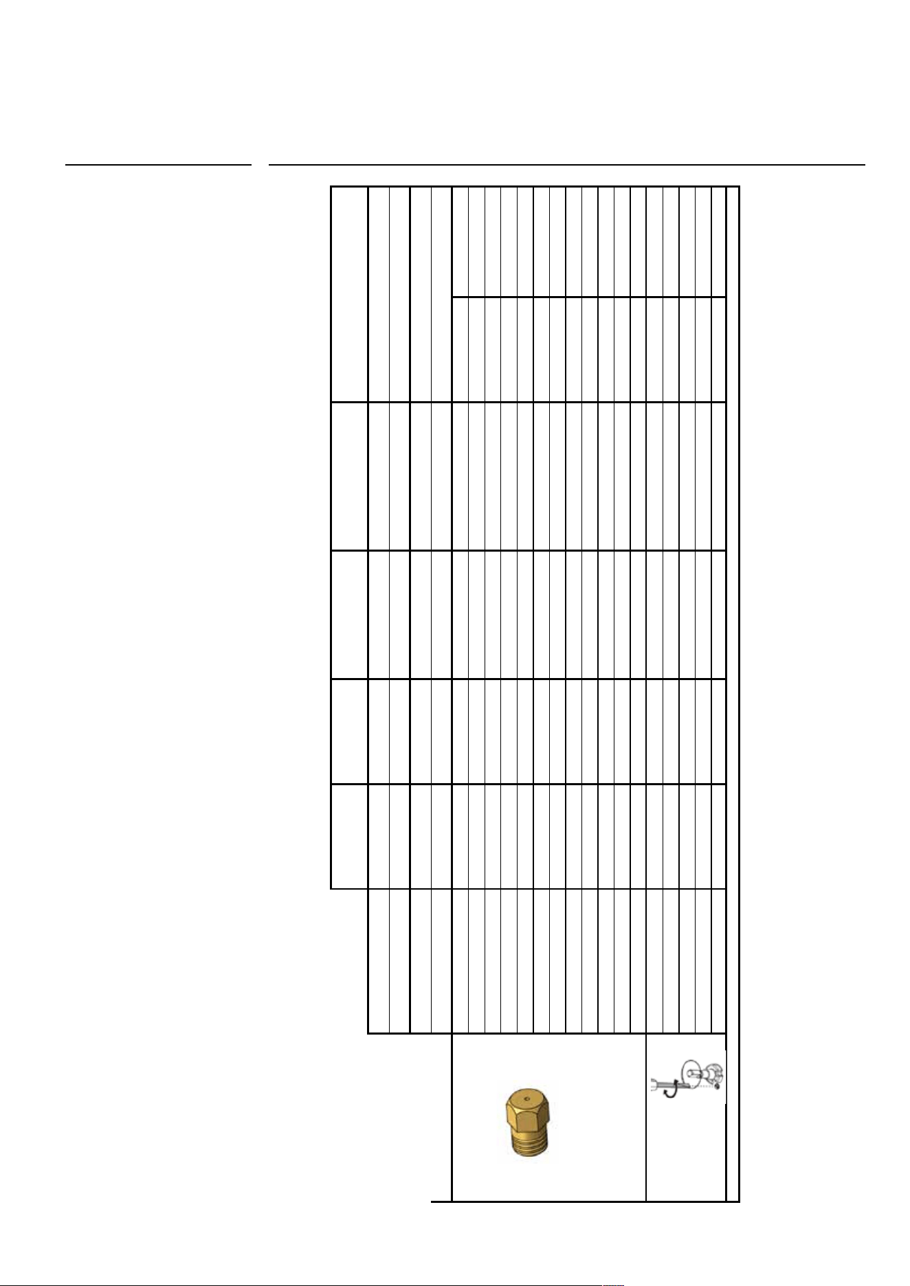
INSTALLATION
Cooking hob table HC60, HC70, HC90
Cooking hob table
PIANI COTTURA
TABELLA PIANI COTTURA ALLEGATO A INFORMATIONS TECHINIQUE DESTINEES AUX ORGANISMES NOTIFIES RIF. TYPE H60CV
SR R P DCC
Qmax kW 1,80 3,00
3,10 / 2,9
(5)
4,20
(4)
/ 4,30 / 3,40
(3)(5)
Qmax g/h 131 218 225
305
(4)
/ 313
Qmin kW
0,40 / 0,51
(1)
/ 0,45
(2)
0,60 / 0,76
(1)
/ 0,66
(2)
1,20 / 1,57
(1)
/ 1,35
(2)
1,70 / 2,20
(1)
/ 1,90
(2)
Qmin g/h
29 / 37
(1)
/ 33
(2)
44 / 55
(1)
/ 48
(2)
87 / 114
(1)
/ 98
(2)
124 / 160
(1)
/ 138
(2)
G30/G31 28..30/37 mbar 0,68 / 0222 0,85 / 0222 0,86 / 0222 1,05 / 0222 0,44 / 0222 0,97 / 0222
G30/G31 50 mbar 0,58 / 0264 0,75 / 0265 0,75 / 0222 0,83 / 0315 0,43 / 0102 0,75 / 0315
G30 37 mbar 0,62 / 0222 0,80 / 0222 0,82 / 0222 1,00 / 0222 0,41 / 0222 0,95 / 0222
G20 20 mbar 0,97 / 0211 1,30 / 0103 1,30 / 0222 1,50 / 1048 0,70 / 0101 1,42 / 1048
G20 25 mbar 0,91 / 0211 1,10 / 0210 1,23 / 0222 1,50 / 0103 0,65 / 0101 1,40 / 0103
G25 20 mbar 1,00 / 0210 1,34 / 0332 1,42 / 0222 1,64 / 0332 0,72 / 0306 1,50 / 0332
G25 25 mbar 0,98 / 0210 1,26 / 0332 1,28 / 0332 1,48 / 0332 0,75 / 0306 1,40 / 0332
G25.3 25 mbar 0,94 / 0210 1,26 / 0332 1,26 / 0332 1,48 / 0332 0,75 / 0306 1,40 / 0332
G2.350 13 mbar 1,26 / 0210 1,64 / 0332 1,70 / 0332 2,10 / 1048 0,91 / 0210 2,10 / 1048
G25.1 25 mbar 0,98 / 0210 1,25 / 0309 1,28 / 0332 1,52 / 0332 0,71 / 0306 1,50 / 0332
G150.1 8 mbar 1,90 / 0224-2 2,75 / 0224-3 2,70 / 0224-6 3,50 / 00003 1,45 / 00004 3,50 / 00003
G110 8 mbar 1,90 / 0224-2 2,75 / 0224-3 2,70 / 0224-6 3,50 / 00003 1,45 / 00004 3,50 / 00003
G30/G31 0,30 0,38 0,56 0,66 0,24 0,65
G20 REG REG REG REG REG REG
G25 REG REG REG REG REG REG
G2.350 13 mbar REG REG REG REG REG REG
G110/G120 REG REG REG REG REG REG
(1)=DE AT (2)=PL (3)=G110 (4)=HC70, HC90C (5)=G150.1
by-pass Ø mm
DUAL
4,50 / 3,80
(3)(5)
327
0,30
22
Ø mm
36
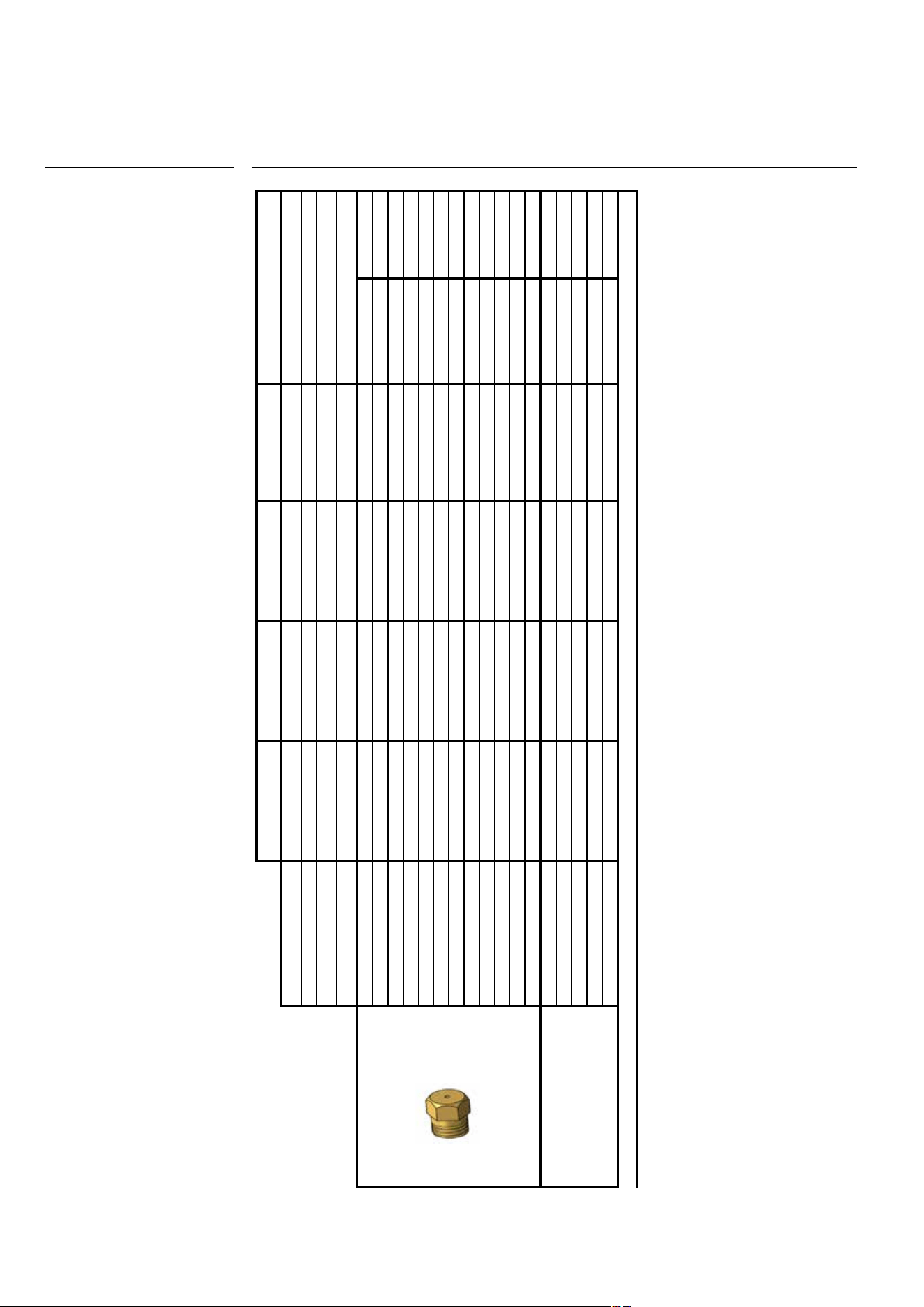
INSTALLATION
Cooking hob table HCP90, HCP120
ILVE S.p.A.
TABELLA INIETTORI/GAS PIANI HCP90 - HCP120 PIN. 1312DL6442
SR R P DCC
Qmax kW 1,80 3,00
3,10 / 3,00
(6)
4,30 / 4,20
(3)
/ 3,8
(4)
Qmax g/h 131 218 225 313
Qmin kW
0,40 / 0,53
(1)
/ 0,45
(2)
0,60 / 0,75
(1)
/ 0,65
(2)
1,10 / 1,20
(1)
1,80 / 2,32
(1)
/ 2,00
(2)
Qmin g/h
29 / 39
(1)
/ 33
(2)
44 / 55
(1)
/ 47
(2)
80 / 87
(1)
131 / 169
(1)
/ 145
(2)
G30/G31 28..30/37 mbar 0,68/0222 0,85/0222 0,87/0222 1,05/0222 0,44/0222 1,04/0222
G30/G31 50 mbar 0,58/0264 0,75/0265 0,75/0265 0,80/0315 0,43/0102 0,83/0315
G30 37 mbar 0,62/0222 0,82/0222 0,82/0222 0,95/0222 0,41/0222 1,00/0222
G20 20 mbar 0,97/0211 1,30/0103 1,30/0222 1,50/1048 0,70/0101 1,52/1048
G20 25 mbar 0,91/0211 1,10/0210 1,23/0222 1,50/0103 0,65/0101 1,50/0103
G25 20 mbar 1,05/0210 1,37/0332 1,42/0222 1,57/0332 0,72/0306 1,57/0332
G25 25 mbar 0,98/0210 1,26/0332 1,35/0222 1,50/0332 0,75/0306 1,50/0332
G2.350 13 mbar 1,26/0210 1,64/0332 1,64/0332 2,10/1048 0,91/210 2,10/1048
G25.1 25 mbar 0,98/0210 1,25/0309 1,28/0332 1,52/0332 0,71/0306 1,52/0332
G25.3 25 mbar 0,94/0210 1,26/0332 1,28/0332 1,48/0332 0,75/0306 1,48/0332
G110 8 mbar 1,90/0224-2 2,60/0224-3 2,70/0224-6 3,50/00003 1,45/00004 3,50/00003
G150.1 8 mbar 1,90/0224-2 2,60/0224-3 2,60/0224-6 3,50/00003 1,45/00004 3,50/00003
G30/G31 0,32 0,40 0,52 0,75 0,27 0,60
G20 REG REG REG REG REG REG
G25 REG REG REG REG REG REG
G2.350 13 mbar REG REG REG REG REG REG
G110/G120 REG REG REG REG REG REG
(1)=G30/G31 50 mbar (2)=G30 37 mbar (3)=G110/G120 8 mbar (4)=G150.1 8 mbar (6)= G2.350 13 mbar
by-pass Ø mm
DUAL
5,00 / 4,20
(3)(4)
364
0,30 / 0,36
(1)
/ 0,31
(2)
22 / 26
(1)
/ 23
(2)
Ø mm
37
INSTALLER
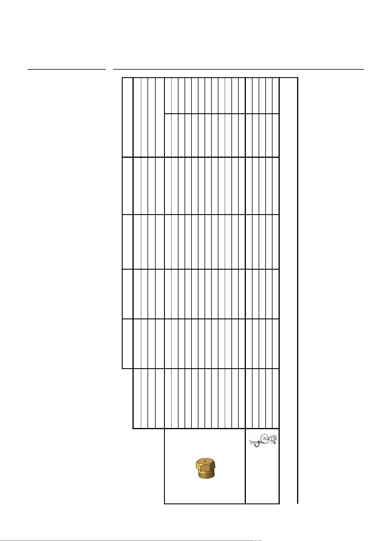
INSTALLATION
Cooking hob table HCP965, HCP1265
ILVE S.p.A.
TABELLA INIETTORI/GAS PIANI HCP965- HCP1265 PIN. 1312DL6442
SR R P DCC
Qmax kW 1,80 3,00
3,10 / 2,90
(4)
4,20
(5)
/ 4,30 / 3,40
(3)(4)
Qmax g/h 131 218 225 313
Qmin kW
0,40 / 0,51
(1)
/ 0,45
(2)
0,60 / 0,76
(1)
/ 0,66
(2)
1,20 / 1,57
(1)
/ 1,35
(2)
1,80 / 2,20
(1)
/ 1,90
(2)
Qmin g/h
29 / 37
(1)
/ 33
(2)
44 / 55
(1)
/ 48
(2)
87 / 114
(1)
/ 98
(2)
124 / 160
(1)
/ 138
(2)
G30/G31 28..30/37 mbar 0,68 / 0222 0,85 / 0222 0,86 / 0222 1,05 / 0222 0,44 / 0222 1,04 / 0222
G30/G31 50 mbar 0,58 / 0264 0,75 / 0265 0,75 / 0222 0,83 / 0315 0,43 / 0102 0,83 / 0315
G30 37 mbar 0,62 / 0222 0,80 / 0222 0,82 / 0222 1,00 / 0222 0,41 / 0222 1,00 / 0222
G20 20 mbar 0,97 / 0211 1,30 / 0103 1,30 / 0222 1,50 / 1048 0,70 / 0101 1,52 / 1048
G20 25 mbar 0,91 / 0211 1,10 / 0210 1,23 / 0222 1,50 / 0103 0,65 / 0101 1,50 / 0103
G25 20 mbar 1,00 / 0210 1,34 / 0332 1,42 / 0222 1,64 / 0332 0,72 / 0306 1,57 / 0332
G25 25 mbar 0,98 / 0210 1,26 / 0332 1,28 / 0332 1,48 / 0332 0,75 / 0306 1,50 / 0332
G2.350 13 mbar 1,26 / 0210 1,64 / 0332 1,70 / 0332 2,10 / 1048 0,91 / 0210 2,10 / 1048
G25.1 25 mbar 0,98 / 0210 1,25 / 0309 1,28 / 0332 1,52 / 0332 0,71 / 0306 1,52 / 0332
G25.3 25 mbar 0,94 / 0210 1,26 / 0332 1,26 / 0332 1,48 / 0332 0,75 / 0306 1,45 / 0332
G110 8 mbar 1,90 / 0224-2 2,75 / 0224-3 2,70 / 0224-6 3,50 / 00003 1,45 / 00004 3,50 / 00003
G150.1 8 mbar 1,90 / 0224-2 2,75 / 0224-3 2,70 / 0224-6 3,50 / 00003 1,45 / 00004 3,50 / 00003
G30/G31 0,30 0,38 0,56 0,66 0,24 0,65
G20 REG REG REG REG REG REG
G25 REG REG REG REG REG REG
G2.350 13 mbar REG REG REG REG REG REG
G110/G120 REG REG REG REG REG REG
(1)=G30/G31 50 mbar (2)=G30 37 mbar (3)=G110/G120 8 mbar
(4)=G150.1 8 mbar (5)=G25 20 mbar (6)=G2.350 13 mbar
by-pass Ø mm
DUAL
5,0 / 3,80
(3)(4)
327
0,30
22
Ø mm
38
INSTALLATION
Cooking hob table HCP95C_D / HCPM95C_D
ILVE S.p.A.
TABELLA INIETTORI/GAS PIANI HCP95C/D
SR R DCC
Qmax kW 1,80 3,00
4,20
(5)
/ 4,30 / 3,40
(3)(4)
Qmax g/h 131 218 313
Qmin kW
0,40 / 0,51
(1)
/ 0,45
(2)
0,60 / 0,76
(1)
/ 0,66
(2)
1,80 / 2,20
(1)
/ 1,90
(2)
Qmin g/h
29 / 37
(1)
/ 33
(2)
44 / 55
(1)
/ 48
(2)
124 / 160
(1)
/ 138
(2)
G30/G31 28..30/37 mbar 0,68 / 0222 0,85 / 0222 1,05 / 0222 0,44 / 0222 0,97 / 0222
G30/G31 50 mbar 0,58 / 0264 0,75 / 0265 0,83 / 0315 0,43 / 0102 0,75 / 0315
G30 37 mbar 0,62 / 0222 0,80 / 0222 1,00 / 0222 0,41 / 0222 0,95 / 0222
G20 20 mbar 0,97 / 0211 1,30 / 0103 1,50 / 1048 0,70 / 0101 1,42 / 1048
G20 25 mbar 0,91 / 0211 1,10 / 0210 1,50 / 0103 0,65 / 0101 1,40 / 0103
G25 20 mbar 1,00 / 0210 1,34 / 0332 1,57 / 0332 0,72 / 0306 1,50 / 0332
G25 25 mbar 0,98 / 0210 1,26 / 0332 1,48 / 0332 0,75 / 0306 1,40 / 0332
G2.350 13 mbar 1,26 / 0210 1,64 / 0332 2,10 / 1048 0,91 / 0210 1,98 / 1048
G25.1 25 mbar 0,98 / 0210 1,25 / 0309 1,52 / 0332 0,71 / 0306 1,50 / 0332
G25.3 25 mbar 0,94 / 0210 1,26 / 0332 1,48 / 0332 0,75 / 0306 1,40 / 0332
G110 8 mbar 1,90 / 0224-2 2,75 / 0224-3 3,50 / 00003 1,45 / 00004 3,50 / 00003
G150.1 8 mbar 1,90 / 0224-2 2,75 / 0224-3 3,50 / 00003 1,45 / 00004 3,50 / 00003
G30/G31 0,30 0,38 0,66 0,24 0,65
G20 REG REG REG REG REG
G25 REG REG REG REG REG
G2.350 13 mbar REG REG REG REG REG
G110/G120 REG REG REG REG REG
(1)=G30/G31 50 mbar (2)=G30 37 mbar (3)=G110 8 mbar (4)=G150.1 8 mbar (5)=G2.350 13 mbar
by-pass Ø mm
DUAL
4,20
(5)
/ 4,50 / 3,80
(3)(4)
327
0,30
22
Ømm
39
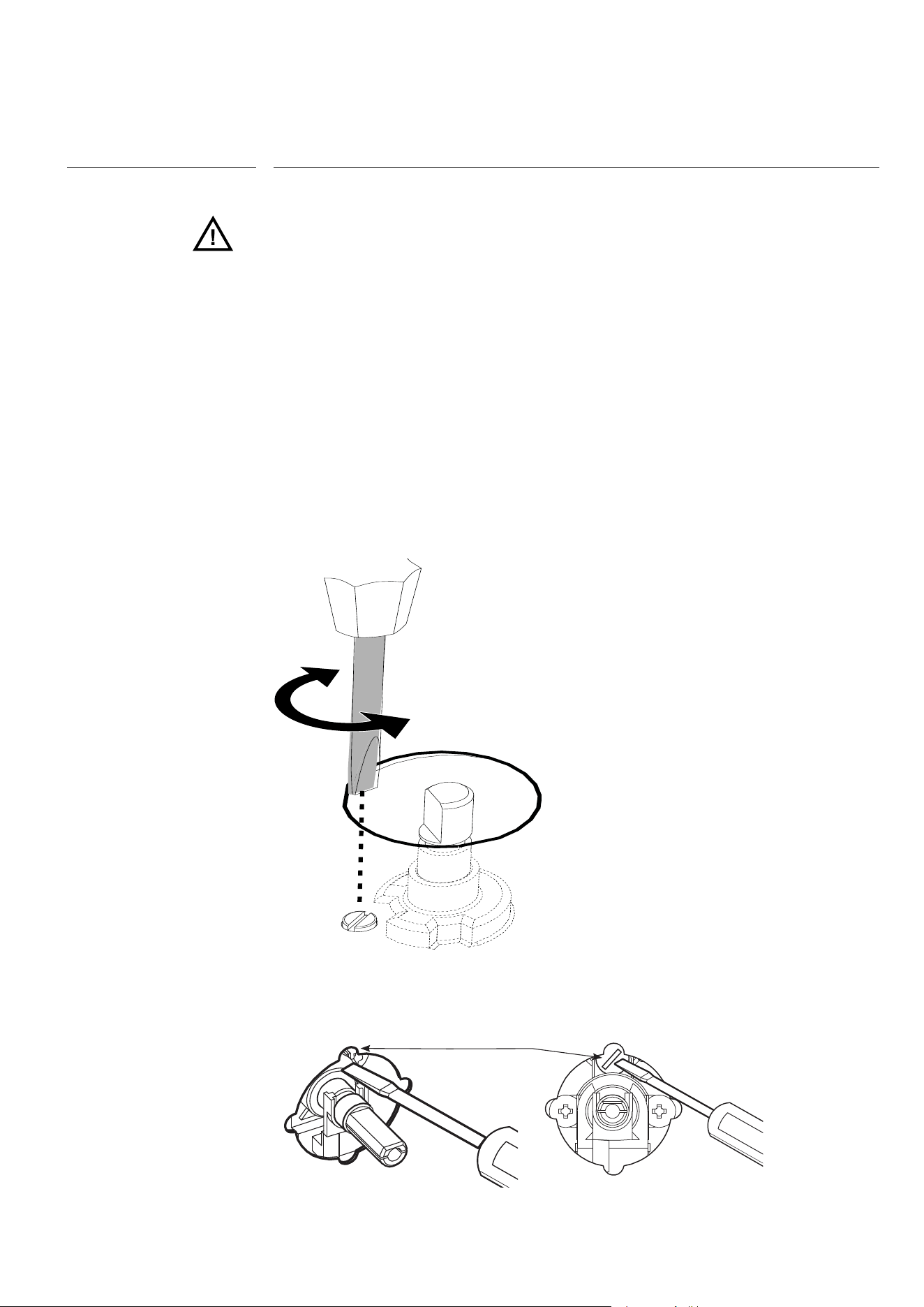
USER
When installing the appliance, we recommend checking that the hob’s burner minimum
has been properly adjusted: a proper adjustment is that when passing from the maxi-
mum position to the minimum position, the flame is reduced, stable and homogeneous.
If the flame on minimum is incorrect or if the gas has been changed, adjustment must
be carried out as follows:
1. Light one burner at a time and turn the flame up to maximum.
2. Remove the knob of the corresponding gas tap.
3. Turn the tap to minimum position.
4. Using a small flathead screwdriver, unscrew, turning to the left, to increase the flame, or
screw to the right to decrease it: the by-pass to be adjusted is indicated by
the figure B1 and B2.
5. If a liquid gas is used (Butane-Propane), the screw (by-pass) must be fully screwed in.
by-pass
Pic. B1
INSTALLATION
Adjustment of minimum
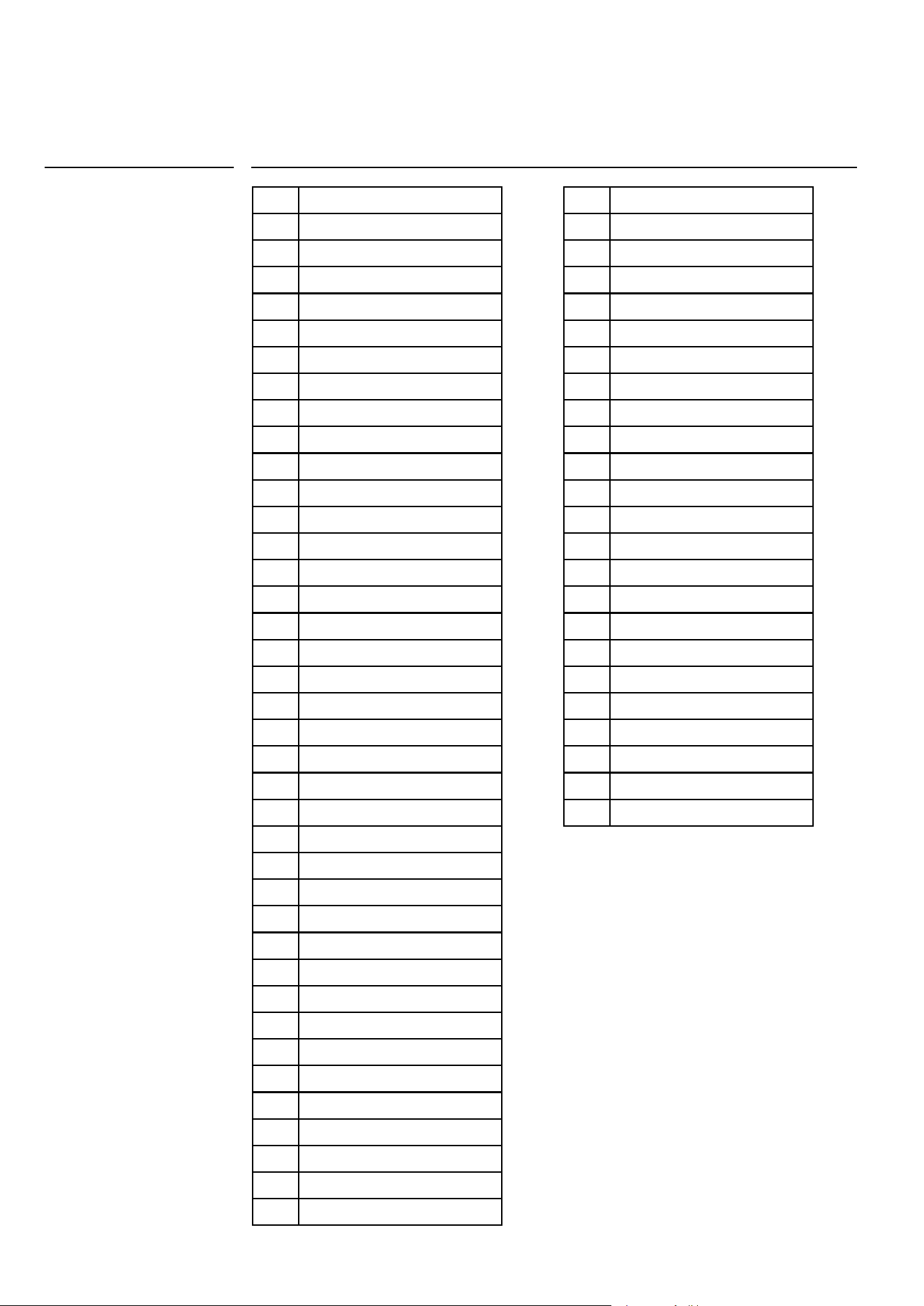
40
00 Black
11 Brown
22 Red
33 White
44 Yellow
45 Yellow-Green
55 Grey
66 Blue
AA Electrical ignition transformer
C Switch
F Phase
K1
Earth wire for terminal board
K2
” ” lower resistance
K3
” ” for oven fan
K4
” ” circular resistance
K5
” ” upper resistance
K6
” ” oven lamp 1
K7
” ” oven lamp 2
K8
” ” rotisserie
K9
” ” cooling fan
K10
” ” selector
K11
” ” oven thermostat
K12
” ” programmer/timer
K13
” ” grill
K14
” ” el. hotplate
K15
” ” frame
K16
” ” barbecue
K17
” ” fryer
L1
Oven lamp
L2
Oven lamp
M
Terminal board
MA
Electrical ignition microswitch
MD
Grill microswitch
MG
Rotisserie
MP
Door microswitch
N
Neutral
P
Timer/Programmer
P
Timer/Clock
PE
Electric hotplate
WIRING DIAGRAMS
Keys
R1
Upper heating element
R2
Lower heating element
R3
Grill heating element
R4
Circular heating element
R5
Barbecue heating element
R6
Fryer heating element
RE
Energy regulator
S1
Oven warning light
S2
Mains power warning light
S3
Grill warning light
S4
Cooling fun warning
S5
Barbecue warning light
S6
El. hotplate warning light
S7
Turnsplit warning light
S8
Residual heat warning light
S9
Fryer warning light
SP
Sparking plug
T
Grill thermostat
TF
Oven thermostat
TR
Fryer thermostat
TS
Safety thermostat
TT
Cooling fan thermostat
V
Oven fan
VT
Cooling fan
Keys
41
USER
K1
M
66
11
P2
22
P3 5
C
33
S6
PE
N F
2
1
3
4
P1
66
11
P2
P3 5
C
2
1
3
4
P1
1
2
4
3
55
44
33
22
33
PE
1
2
4
3
55
44
33
K14 K15
45
AA
SP
66
MA
MA
MA
MA MA
11
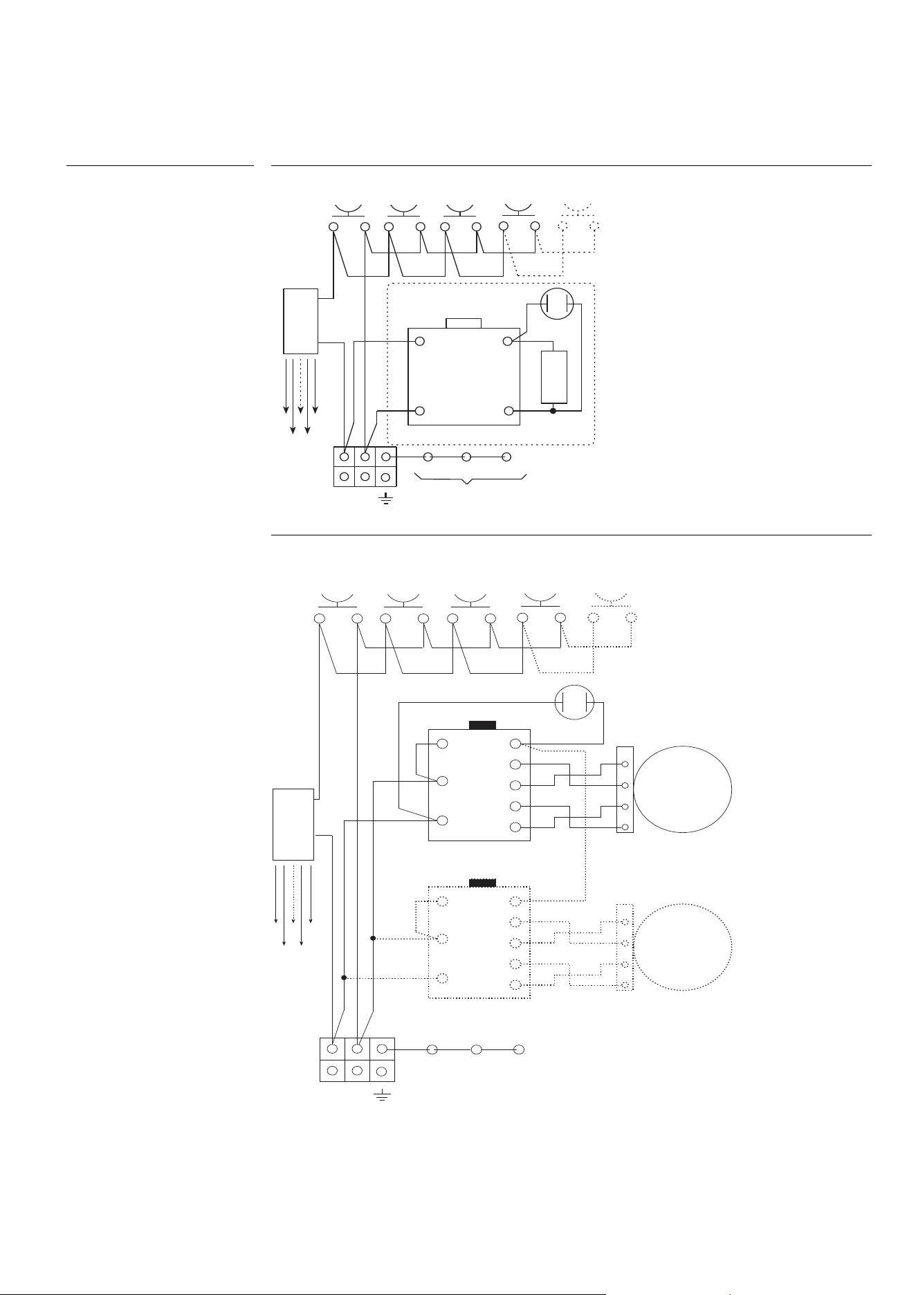
Models H392…, H391…
SP
AA
66
11
11
MA
MA
MA
RE
00
S5
MA MA
N F
M
11
66
P2 4
00
P1 2
00
R5
K1 K15 K16
45
§
WIRING DIAGRAMS
§ = only models with
electric barbecue

42
• During the warranty period repairs can only be carried out by the authorized After-Sa-
les Service.
• Before repairing, disconnect the appliance from the mains, ie, disconnect the power
cord or unscrew the fuse.
• Unauthorized interventions and repairs may cause electrocution or short circuit,
so do not perform them. Leave this work to authorized technicians.
• In the case of minor disturbances you can try to solve the problem by fol-
lowing the instructions.
• The assistance service during the warranty is not free, if the device does not work for
incorrect use.
• The elimination of faults or complaints, which were caused by use or incorrect instal-
lation, will not be repaired under warranty. Warranty costs will be charged
to the user.
Below you will find some advice on rectifying some common problems.
If the problem persists despite observing the instructions above, call the authorised
after-sales service.
TROUBLESHOOTING
Troubleshooting Guide
PROBLEM
The flame is not uniform.
The flame changes suddenly.
To light the burners, keep
the ignition knob pressed for
longer.
After ignition the flame goes
out.
The grill in the burner area has
changed color.
Electrical operation is general-
ly disturbed.
The electric ignition no longer
works.
The burner lids are dirty.
POSSIBLE CAUSE
Gas regulation not suitable.
The burner parts are not posi-
tioned correctly.
The burner parts are not posi-
tioned correctly.
The knob was not pressed
long enough or was pressed
too gently.
A natural phenomenon due
to the high temperature.
Igniter or terminal block da-
maged.
Food or detergent residues
between the ignition electro-
de and the burner.
Normal dirt.
ELIMINATION
The gas regulation must be
controlled by an expert
Position the burner parts
correctly.
Position the burner parts
correctly.
Keep the knob pressed lon-
ger, before releasing it, press
strongly.
Clean the grill with metal
cleaning detergent.
Check the ignition and / or the
terminal block and replace it
if it is damaged.
Clean carefully between the
ignition electrode and the
burner.
Clean the lids with metal clea-
ning detergent.

NOTES