
Contents
目录
Contents .......................................................................................................................................................... 2
1.
Package Contents ............................................................................................................................. 1
2.1. Parameters .................................................................................................................................. 2
2.2. Receiver module Interfaces ........................................................................................................ 3
2.3. Transmitter module Interfaces .................................................................................................... 4
3.
System setup ..................................................................................................................................... 6
3.1. Receiver module Installation ...................................................................................................... 6
3.1.1. Antenna installation ........................................................................................................ 6
3.1.2. Power supply .................................................................................................................. 6
3.1.3. Connect camera .............................................................................................................. 7
3.2. Transmitter module installation .................................................................................................. 7
3.2.1. Antenna installation ........................................................................................................ 7
3.2.2. Power supply .................................................................................................................. 8
3.2.3. Telemetry connection ..................................................................................................... 9
3.2.4. Setup video output .......................................................................................................... 9
3.2.5. Use Taisync system ........................................................................................................ 9
4.
Device Management ....................................................................................................................... 12
4.1. Webpage Configuration ........................................................................................................... 12
4.2. Link performance ..................................................................................................................... 14
4.3. Firmware update ....................................................................................................................... 15
4.4. Bind operation .......................................................................................................................... 16
4.5. PC Windows firewall ............................................................................................................... 17
4.6. Set PC IP address ..................................................................................................................... 18
5.
FAQ ................................................................................................................................................ 19
FCC Warning ....................................................................................................................................... 24
1
1.
Package Contents
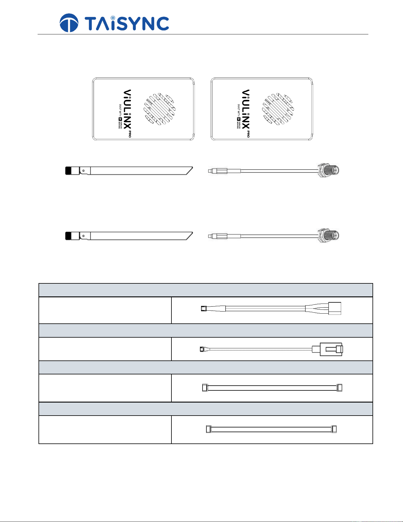
Receiver module & Transmitter module
Receiver module antenna & adaptation cable × 2
(antenna for Receiver module) (adaptation cable for Receiver module)
Transmitter module antenna & adaptation cable × 2
(antenna for Transmitter module) (adaptation cable for Transmitter module)
Receiver module Cables
Power cable x1
This is used to connect the output of a battery to the
power input of the Receiver module.
RJ45 cable x1
This is used to connect the ETH output of a camera
to the ETH input of the Receiver module.
cable x1
This is used to connect the Control bus port of
Transmitter module to the port of the Receiver
module.
Serial cable x1
This is used to connect the telemetry port of
Transmitter module to the serial port of the
Receiver module.
2
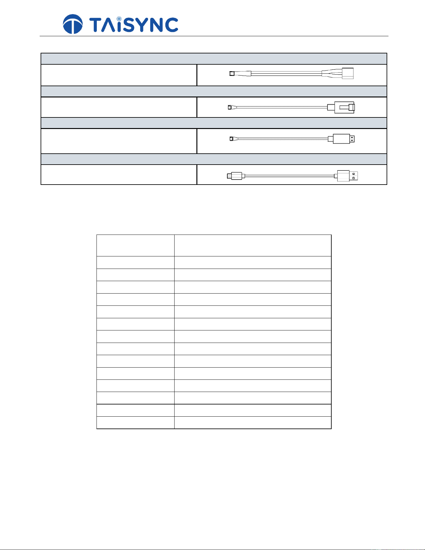
Transmitter module Cables
Power cable x1
This is used to connect the output of a battery to the
power input of the Transmitter module.
RJ45 cable x1
This is used to connect the ETH output of Transmitter
module to the ETH input of a pc.
Serial cable(UART) x1
This is used to connect the telemetry port of
Transmitter module to the serial port of the
Transmitter module.
USB cable (Micro to Type-A)×1
This is used to connect the USB port of a PC to the
Micro USB port of the Transmitter module.
2.
Product Description
2.1. Parameters
Frequency
2.4GHz
Band width
10MHz (uplink), 10MHz(downlink)
Modulation
OFDM
Constellation
BPSK, QPSK, 16QAM
FEC
LDPC (1/2, 2/3, 3/4, 5/6)
Duplex
TDD
Downlink throughput
2.3Mbps ~ 8Mbps
Uplink throughput
600kbps
Encryption
AES 256
Interface
Ethernet, Serial, CONTROL BUS
Dimension
77.8X47.3X23.5mm
Weight
97g
Rated voltage/current
DC 9~26V/1.2A (or 3S lithium battery)
Working temperature
-40°C ~60°C
3
①
② ③ ④ ⑤
① ②③
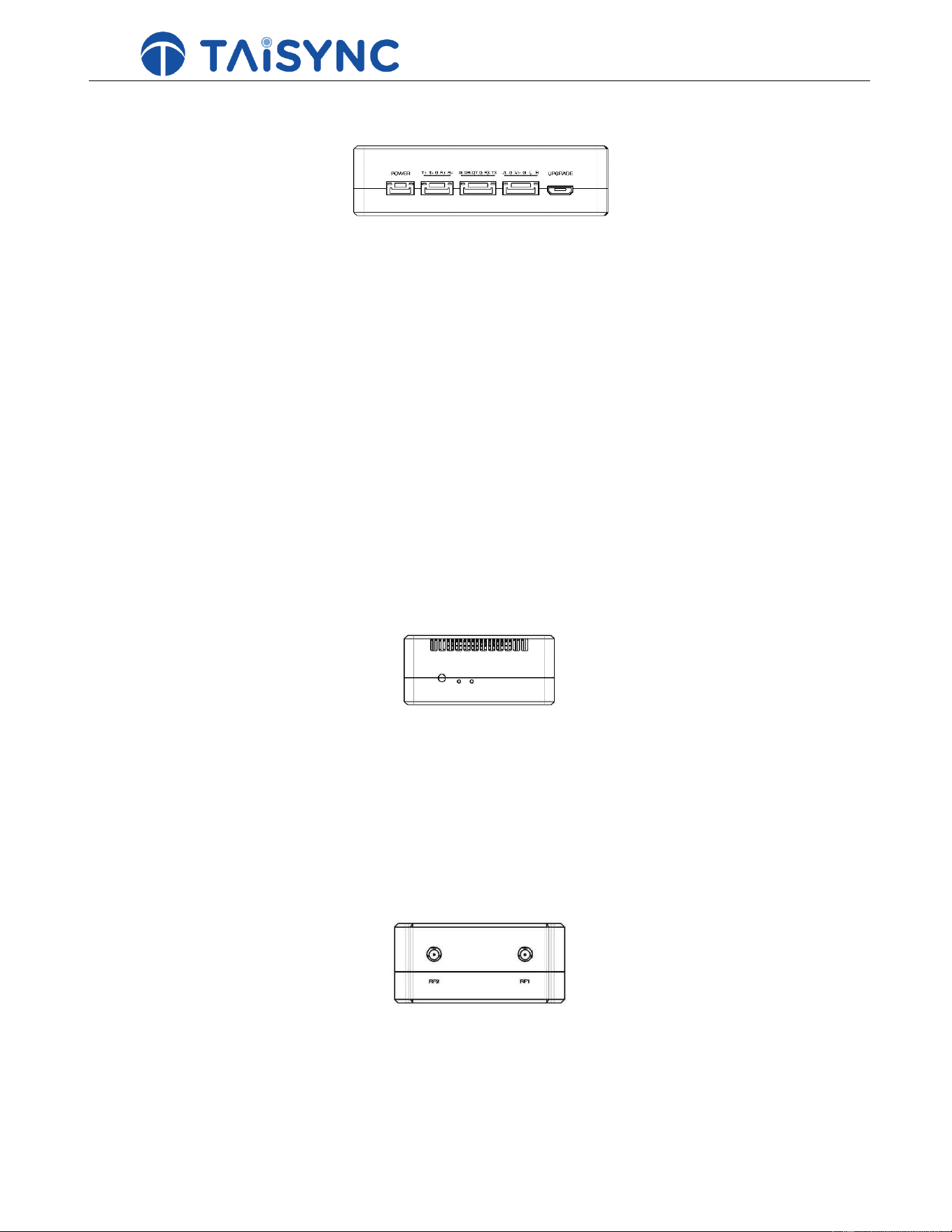
2.2. Receiver module Interfaces
① Power Input Port
Connect a 24V power soue to this port. Recommended power supply is 6S battery.
② RJ45 Port
Connect the Ethernet output of camera to the Ethernet input of the Receiver module.
③ Serial Port (UART)
Connect this port to the telemetry port of a Transmitter module for telemetry communication
with the Transmitter module. UART signal: LVCMOS-3.3V.
④ Control Port
Connect this port to the Control BUS port of a Transmitter module for Control communication
with the Transmitter module. Pin V + can provide 5V power supply.
⑤ Micro USB Port
Used for debugging.
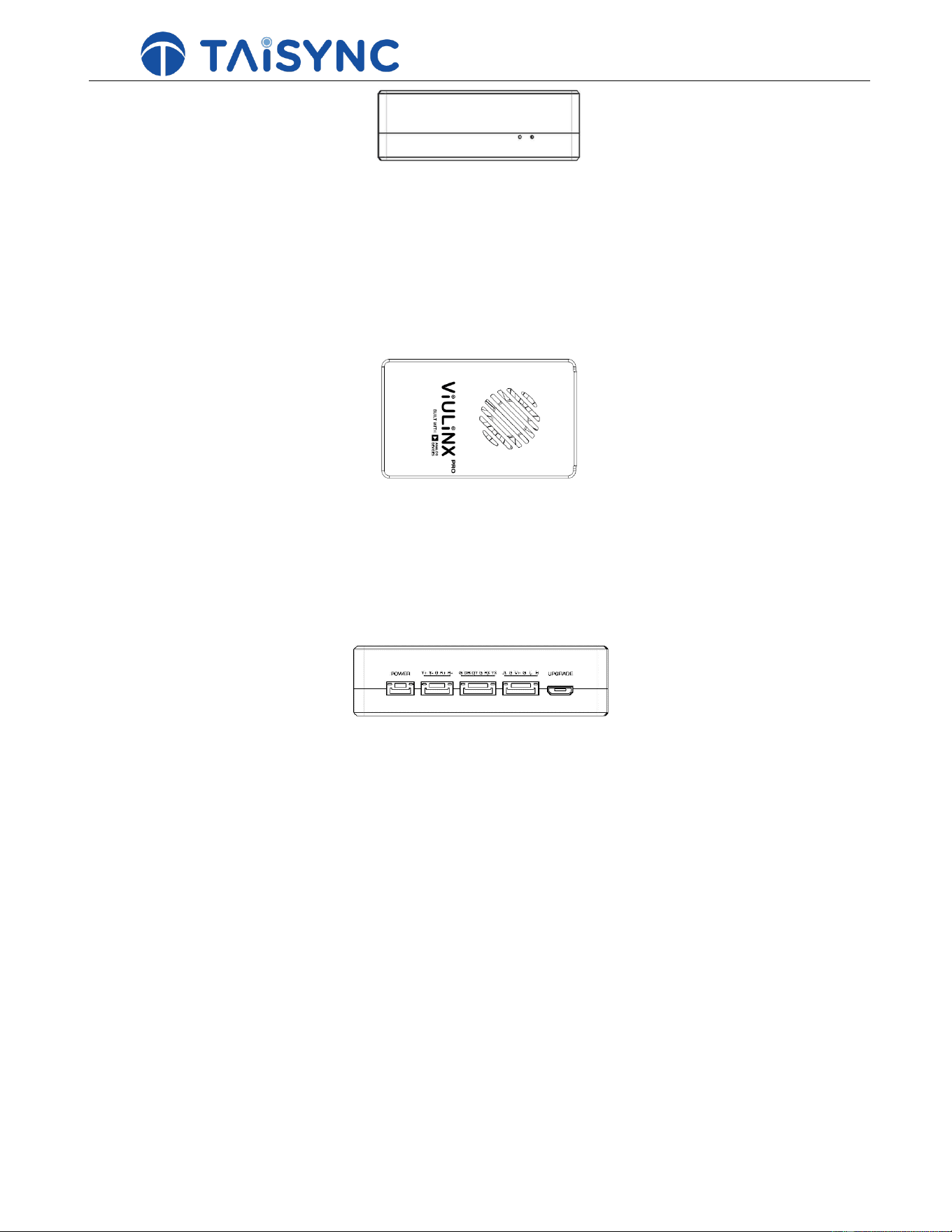
① Bind Button
Press-and-hold this button to perform the binding operation.
② LED 1
③ LED 2
It’s off during radio connection.
LED2 will be flashing in green when Receiver module is under binding mode. It’s off during radio
connection.
① RF2 Port
Connect the 2nd Receiver module antenna to this port.
② RF1 Port
Connect the 1st Receiver module antenna to this port.
①
②
4
② ② ③ ④ ⑤
① LED3
② LED4
When this LED is flashing, it means the Ethernet data link is connected; otherwise, it means the data
link of the Ethernet network is disconnected.
When this LED is on, it means the physical link of the Ethernet port is connected; when this LED is off,
it means the physical link of the Ethernet port is disconnected.
① Fan Ventilation Outlet
Don’t block this fan ventilation outlet to ensure effective cooling.
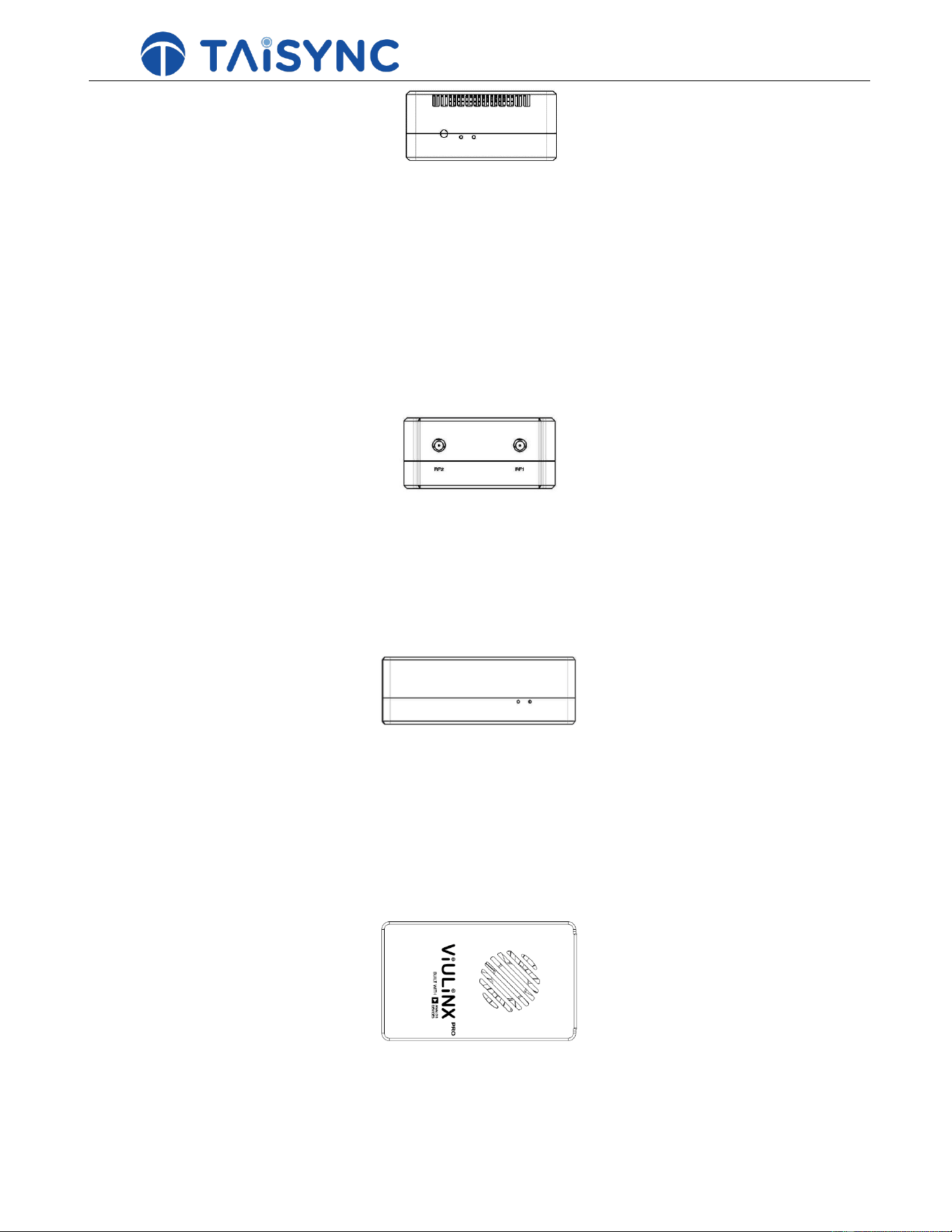
2.3. Transmitter module Interfaces
① Power Input Port
Connect a 24V power soue to this port. Recommended power supply is DC 24V.
② RJ45 Port
Connect this Ethernet output port to the Ethernet input port of a PC using the supplied RJ45 cable.
③ Serial Port (UART)
Connect this port to the telemetry port of a Transmitter module, or the serial port of a Transmitter
module station to setup a telemetry link between the Receiver module and the Transmitter module
station. UART signal: LVCMOS-3.3V.
④ Control Port
Connect this port to the Control BUS port of a Transmitter module. Pin V + can provide 5V power
supply.
⑤ Micro USB Port
Used for debugging.
①
①
②
5
①
②
①
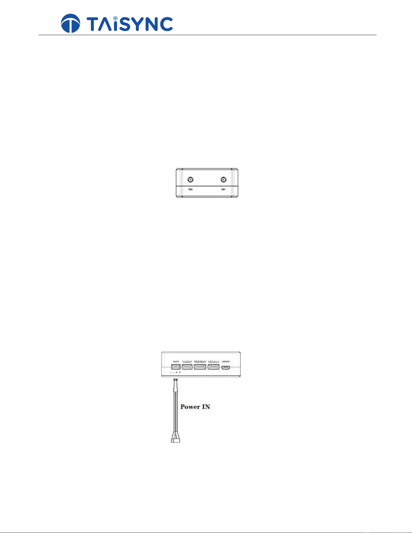
① Bind Button
Press-and-hold this button to perform the binding operation.
② LED 1
③ LED 2
When this LED is on, it means the The Receiver And Transmitter module link is connected; when
this LED is off, it means the Receiver module And Transmitter module link is disconnected.
When this LED is on, it means the Receiver module And Transmitter module link is connected; when
this LED is off, it means the Receiver module And Transmitter module link is disconnected.
① RF2 Port
Connect the 2nd Receiver module antenna to this port.
② RF1 Port
Connect the 1st Receiver module antenna to this port.
① LED3
When this LED is flashing, it means the Ethernet data link is connected; when this LED is off, it means
the data link of the Ethernet network is disconnected.
② LED4
When this LED is on, it means the physical link of the Ethernet port is connected; when this LED is off,
it means the physical link of the Ethernet port is disconnected.
① Fan Ventilation Outlet
Don’t block this fan ventilation outlet to ensure effective cooling.
①
②
③ ②③
6
3.
System setup
3.1. Receiver module Installation
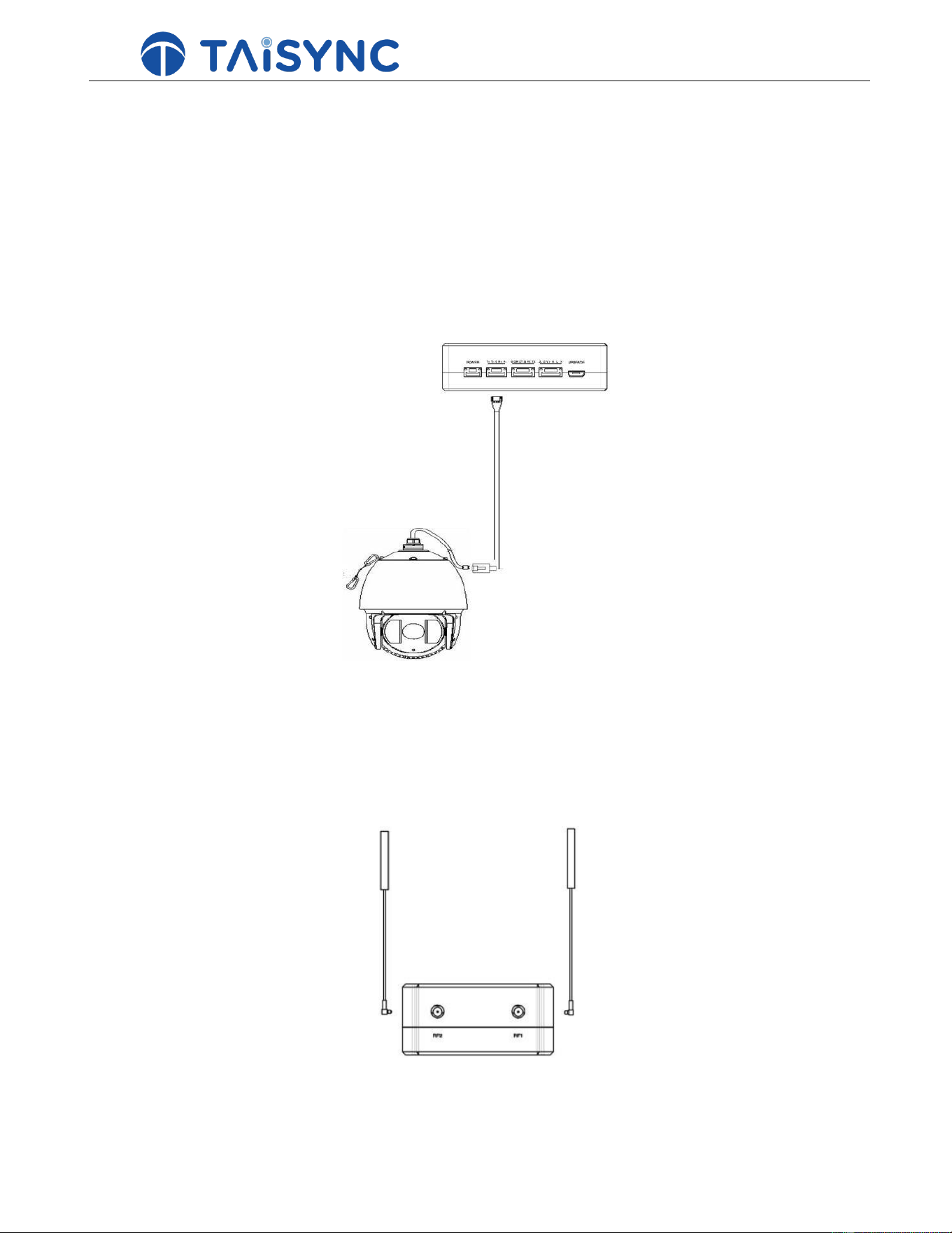
3.1.1. Antenna installation
Insert the Receiver module antennas into the RF ports. Antenna connector clicks in when properly installed.
Note:
1. To avoid equipment damage, install antennas before powering on the module
2. Both antennas need to be installed.
3. Ensure the antenna connector is vertical to the module when it is pushed into the RF port.
4. Do not pull the cable to uninstall the antenna. Hold the connector and pull it vertically out of the RF port to
uninstall antennas properly.
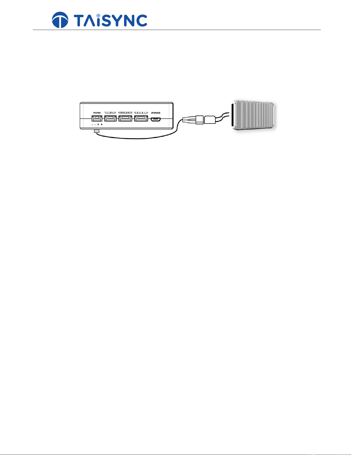
3.1.2. Power supply
7
Pin-out: - - + +. Insert the four-pin connector of supplied power cable to the power port of the Receiver
module and connect the orange power connector of supplied power cable to a battery output, or the power
supply port of a Receiver module. Recommended voltage is 24V.
Note:
1. To avoid equipment damage, install antennas before powering on the units.
2. Recommended rated voltage/current is DC 24V/1.2A
3.1.3. Connect camera
Connect the Ethernet video output port of a camera to the Ethernet video input port of the Receiver module.
3.2. Transmitter module installation
3.2.1. Antenna installation
Insert the Transmitter module antennas into the RF ports. Antenna connector clicks in when properly installed.
Note:
1. To avoid equipment damage, install antennas before powering on the units.
8
2. Both antennas need to be installed.
3. Ensure the antenna connector is vertical to the module when it is pushed into the RF port.
4. Do not pull the cable to uninstall the antenna. Hold the connector and pull it vertically out of the RF port to
uninstall antennas properly.
3.2.2. Power supply
Insert the power connector of a power soue into the power port of the Transmitter module.
Note:
1. Recommended rated voltage/current is DC 24V/1.2A
2. To avoid equipment damage, install antennas before powering on the units.
9
3.2.3. Telemetry connection
Insert the six-pin connector of supplied serial cable to the serial port of the Transmitter module and connect the
other end of supplied serial cable to the telemetry port of the Transmitter module station.
Note:
1. Ensure the baud rate of Transmitter module's serial port and the baud rate of Taisync module's serial port are
configured to be the same.
2. Ensure the pin-out of serial cable matches the pin-out of Taisync module's serial port.
3.2.4. Setup video output
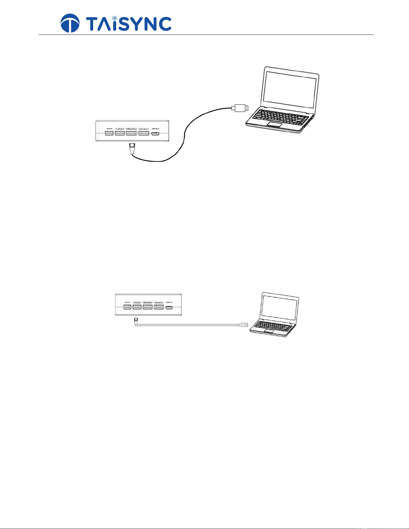
Transmitter module can output video over Ethernet cable to a PC
Note:
To get the video on PC, connect the Ethernet port of the Transmitter module to the Ethernet port of a PC, the IP
address of the PC is configured in the same subnet with camera.
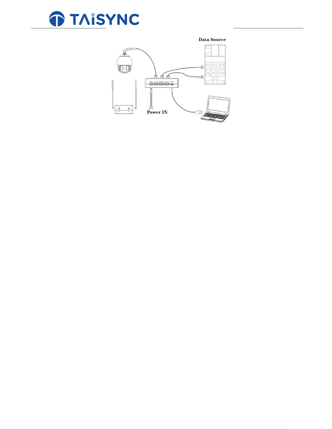
3.2.5. Use Taisync system
10
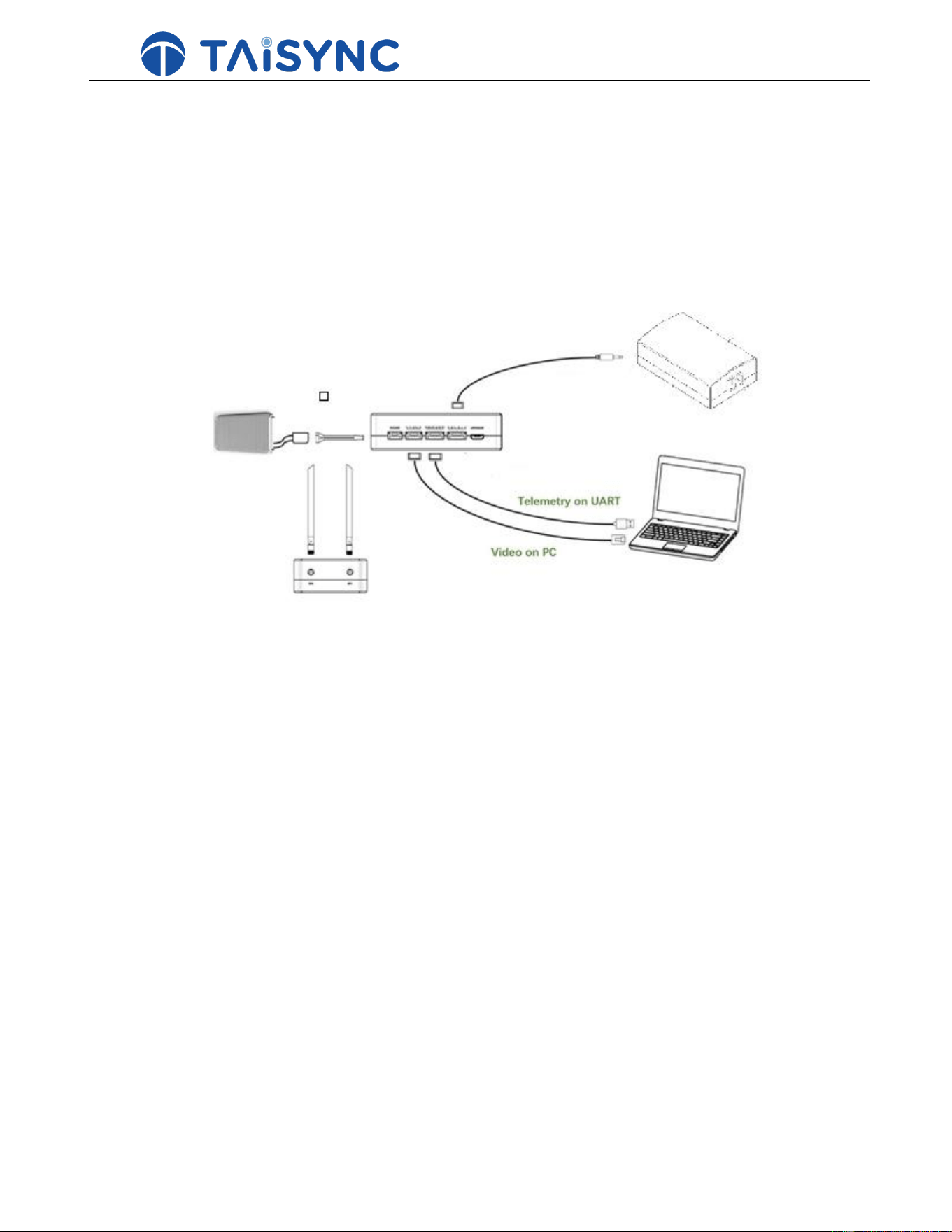
1. Install antennas to the Receiver module.
2. Connect camera’s Ethernet video output to Ethernet port of the Receiver module.
11
3. Connect the DATA port of the Transmitter module to the port of the Receiver module.
4. Connect the telemetry port of the Transmitter module to the serial port of the Receiver module.
5. Turn on the camera and set the PC IP address in the same subnet of camera.
6. Connect a 24V DC power source to the power port of the Receiver module and turn it on.
7. If the latest firmware is needed, can upgrade through Web UI. For further details go through the next topic
Device management.
1. Install antennas to the Transmitter module.
2. Connect the USB port of a Transmitter module station to the serial port of the Transmitter module through a
TTL-2-USB adaptor if you want to use telemetry link.
3. Connect a PC to the Ethernet port of the Transmitter module.
4. Connect a 24V DC power to the power port of the Transmitter module and turn on the power.
5. If the latest firmware is needed, can upgrade through Web UI. For further details go through the next topic
Device management.
6. After downlink and uplink are established, both LEDs of the Transmitter module will be on.
12
4.
Device Management
4.1. Webpage Configuration
Equipment management can be done via webpage. Management IP address of Transmitter module is 192.168.199.16 by
default, and 192.168.199.18 for Receiver module.
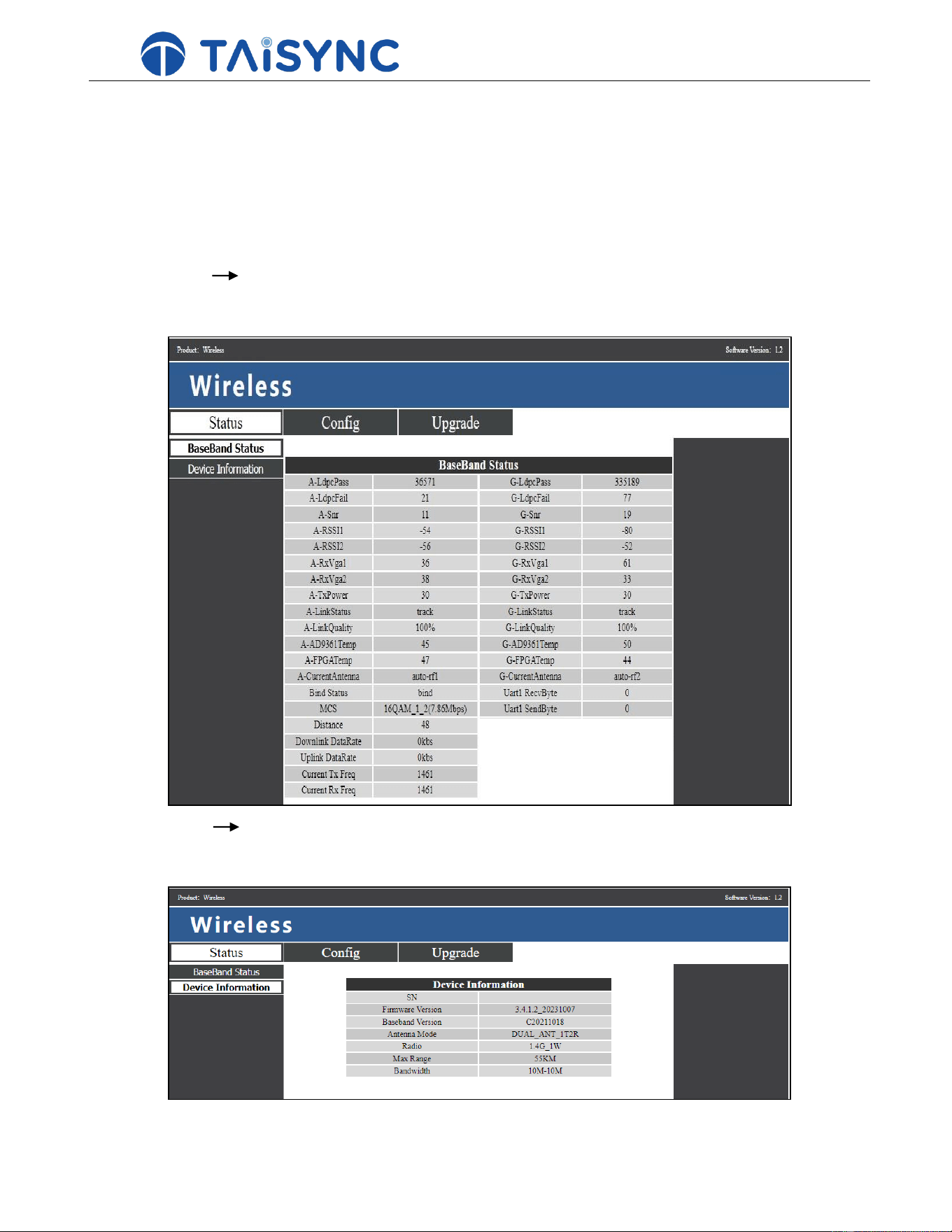
At page of StatusBaseband Status, there’re detailed real-time information displayed, like LDPC, RSSI, SNR, link
status, etc.
At page of StatusDevice Information, there’re SN, software version, Antenna mode, Radio, Bandwidth and
Maximum communication range.
13
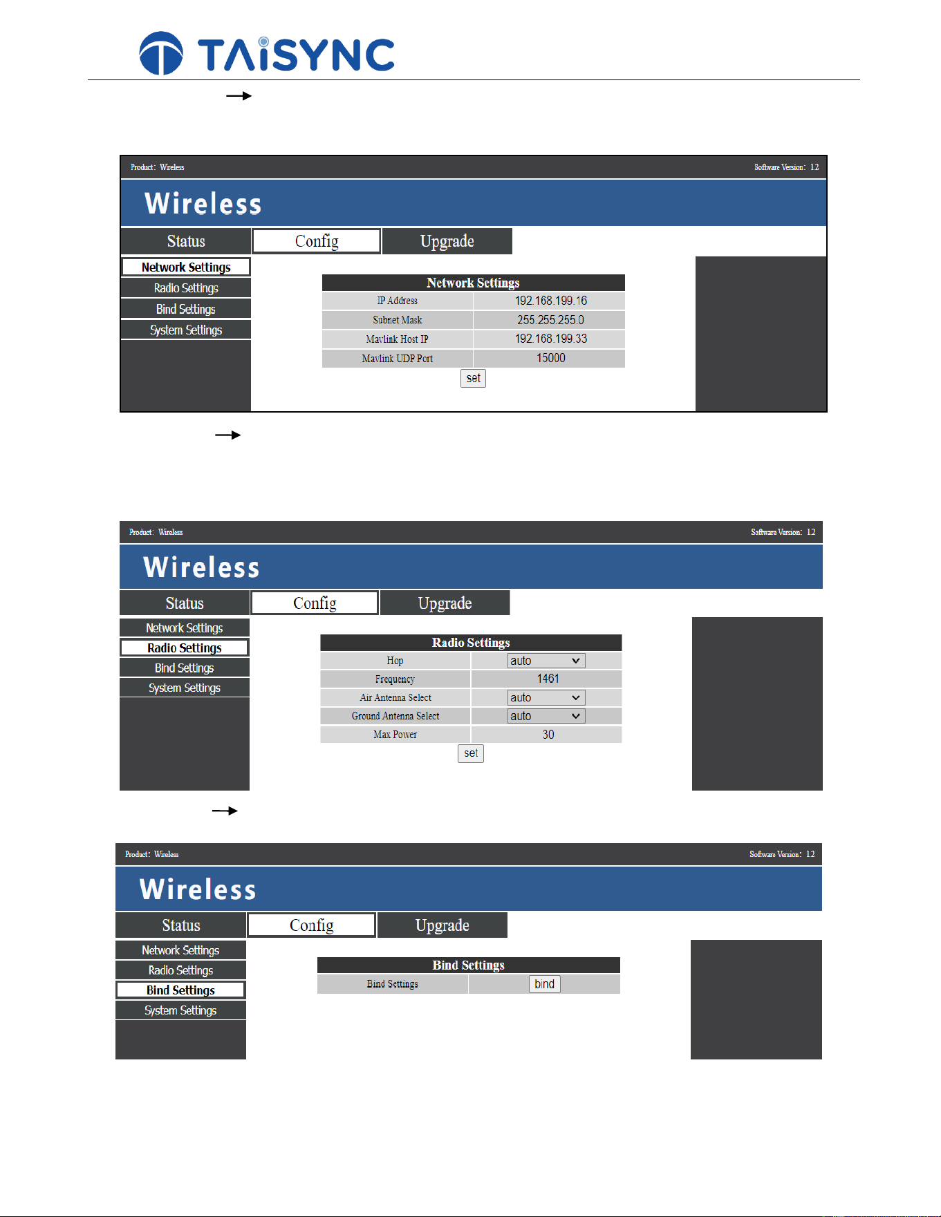
At page of Config Network Settings, user can configure equipment IP address of Transmitter module and
telemetry destination IP address/UDP port.
At page of ConfigRadio Settings, frequency hopping can be enabled/disabled by selecting auto/manual; frequency
can be manually input when hop is manual; options of auto/antenna1/antenna2 are available for antenna select of both
Receiver module and Transmitter module.
At page of ConfigBind Settings, bind can be done by clicking bind button.
14
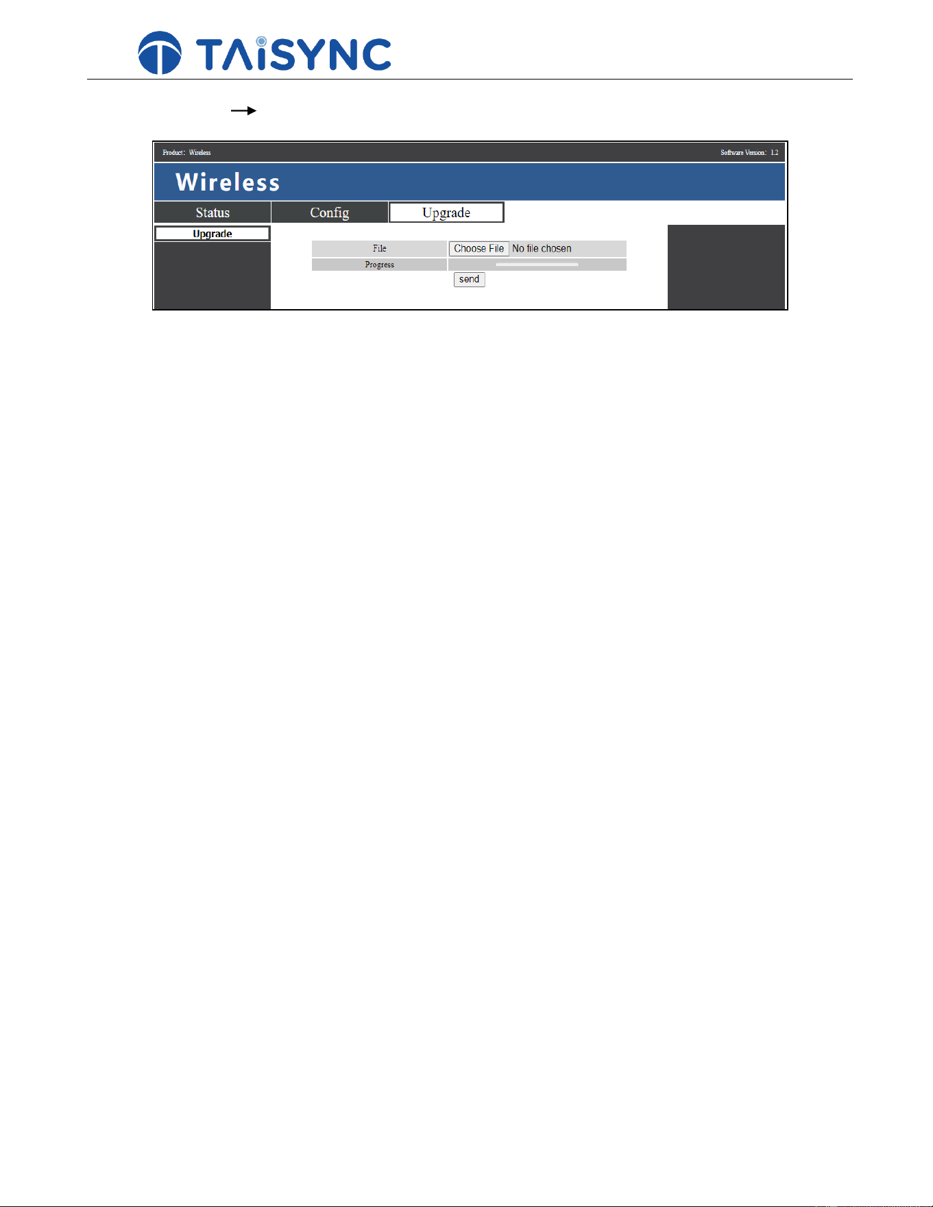
At page of
Upgrade
Upgrade
, firmware replacement can be done.
4.2. Link performance
Interference from 2.4GHz WiFi
WiFi operates at 2.4GHz band with bandwidths of 20MHz and 40MHz. WiFI can generate both co-channel
interference and adjacent channel interference to the 2.4GHz wireless link of a Receiver module. Even if there is
not a WiFi router is available for a WiFi device (for example, WiFi of a phone) to connect with, a WiFi device
periodically transmits beacon/probe signals. So, when you operate a Receiver module in the field with 2.4GHz
wireless link, it is important to turn off WiFi modem/hotspot of a phone, or a laptop.
Interference from Bluetooth device
Bluetooth operates on 2.4GHz in frequency hopping mode. So a Bluetooth mouse, Bluetooth joystick, car key or
any Bluetooth device that is actively working and next to Transmitter module will interfere the reception of
downlink video. Please avoid using Bluetooth device when operate a Receiver module with 2.4GHz wireless link.

15
Interference from wireless device in co-existence
Another wireless device that operates on bands close to 2.4GHz and the device is placed close to the Receiver
module’s 2.4GHz wireless module can interfere the Receiver module’s wireless link. For example, some
Receiver modules have both LTE link and point-2-point wireless link. Particularly, the LTE operating on 2.3GHz
band can be a problem. If the antenna of the LTE module is placed close to the antenna of the 2.4GHz point-2-
point wireless module, the receiver of 2.4GHz module can be saturated by the LTE signal when it is transmitting.
Thus, the range/performance of the 2.4GHz module will be significantly degraded.
Interference from HDMI
When HDMI source/cable is close the antenna of 2.4GHz wireless modem, the HDMI source/video will interfere
the 2.4GHz wireless signal (including WiFi).
https://h30434.www3.hp.com/t5/Notebooks-Ahive-Read-Only/HDMI-interfering-with-WiFi-connectivity/td-
p/4535026
http://www.dslreports.com/forum/r27141612-HDMI-connect-interferes-with-wifi
Interference from USB3.0 divider/hub
USB3.0 dividers or hubs may cause EMI to wireless device. When using USB3.0 dividers or hubs, please check if
EMI is existing.
RF cable connector/Antenna connector check
Before , check if the antennas are connected to the modules. Running module without antenna connected results
in very short range and potentially can damage the module. It is recommended to check the connection of all RF
connectors. Loose connection can degrade the range significantly.
4.3. Firmware update
Upgrade files: FPGA upgrade file for Receiver module, FPGA upgrade file for Transmitter module, MCU1
upgrade file for Receiver module, MCU1 upgrade file for Transmitter module, MCU2 upgrade file for Receiver
module, MCU2 upgrade file for Transmitter module.
Upgrade files are upgraded using web UI. During the upgrade, the power can not be powered off and the normal
connection of ETH cable should be ensured at the same time. If the upgrade fails, the power can not be powered
off, please try to upgrade again directly. Otherwise, it will be necessary to return to us to use special burning tools

16
for firmware burning.
4.4. Bind operation
“Bind” is used to Receiver module with Transmitter module.
To Receiver module and a Transmitter module:
1. Both Receiver module and Transmitter module are powered on.
2. Connect the Receiver module and Transmitter module.

17
3. Press the physical bind button of the Receiver module, last 5s+. The LED light next to the bind button flashes
green, indicating that it is in the binding state.
4. Press the physical bind button of the Transmitter module, last 5s+. The LED light next to the bind button
flashes green, indicating that it is in the binding state.
5. When the link indicator LEDs of Transmitter module are always on, it indicates that the Receiver module and
Transmitter module is binded.
Note:
1. If modules binding with different firmware version, the binding operation may fail.
2. If the program of the Receiver module or the Transmitter module is burned incorrectly, such as burning the
Receiver module to the Transmitter module, and performing the binding operation between the wrong Receiver
module and the Transmitter module, the binding operation will fail.
3. Units are bound already before factory delivery, customer do not need to bind again after unboxing.
4. If unit is restored to factory setting, bind again is needed.
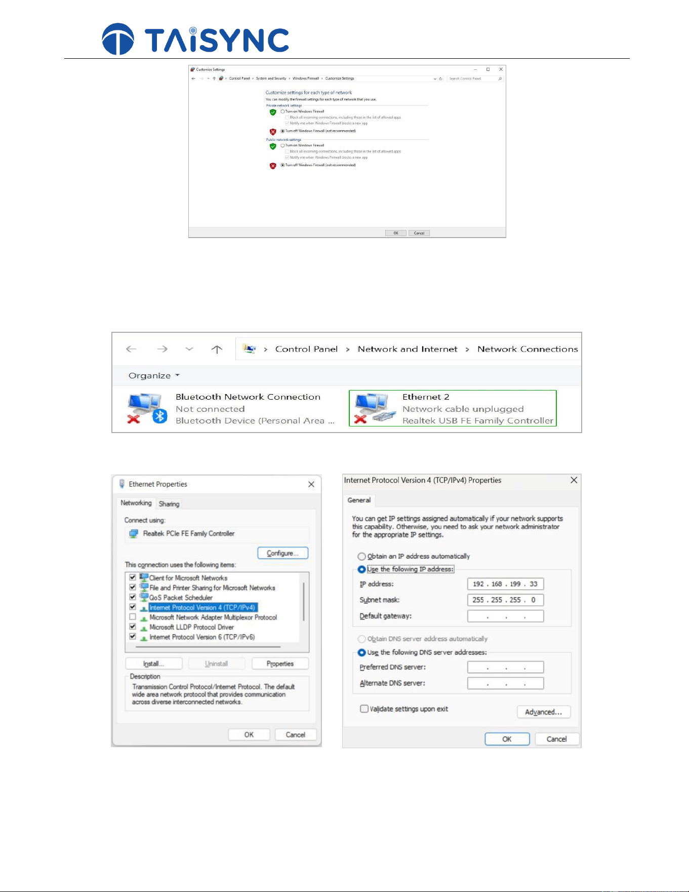
4.5. PC Windows firewall
Make sure PC firewall is disabled in case video and/or telemetry is blocked. Here take Windows10 operation
system for reference. Path: Control Panel\System and Security\Windows Firewall\Customize Settings.
Set Private/Public network settings as 'Turn off Windows Firewall' as below, click 'OK'.
18
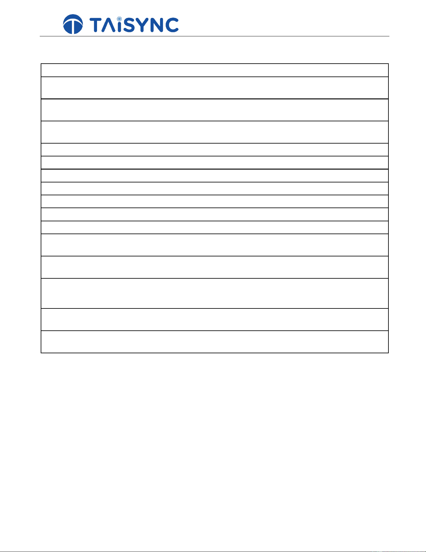
4.6. Set PC IP address
PC IP address should be set in the same subnet with camera, IP address can be set following below steps:
Double click ‘Ethernet’ at Control Panel\Network and Internet\Network Connections.
Double click ‘Internet protocol version 4(TCP/IPv4)’, set PC IP address like below, click 'OK' to finish.
19
5.
FAQ
Q1: How does the Taisync module supply power?
New hardware version Ethernet port unit: DC, power supply range: 24V, recommended to use 24V,
Taiysnc provides power supply cables.
HDMI port Transmitter module: DC, power supply range: 9-26V, recommended to use 24V, Taiysnc
provides power supply cables.
HDMI+AV/SDI+AV Receiver module: DC, power supply range: 9-26V, recommended to use
24V, Taiysnc provides power supply cables.
Q2: Can the Taisync module be powered on before antennas installation?
The antennas must be installed before power on.
Q3: How many antennas do Taisync's Receiver module need to be installed?
Two antennas need to be installed.
Q4: How many antennas do Taisync's Transmitter module need to be installed?
Two antennas need to be installed.
Q5: Can two Transmitter modules be installed at the receiving end?
The ptp system can only install one Transmitter module; the ptmp system supports more than one
Transmitter modules.
Q6: There are some devices nearby, such as WIFI, Bluetooth and so on. Can they be opened when
flying?
If 2.4GHz Taisync modules used, make sure to turn off WIFI, Bluetooth and other functions of other
devices like mobile phone, car key, because these devices are working in 2.4 GHz band, it can cause
interference.
Q7: There are USB3.0 hub and/or HDMI cable used, will they affect the Taisync wireless system?
If 2.4GHz Taisync modules used, make sure to keep USB3.0 hub and/or HDMI cable away from
antenna.
20
Q8: What do the four LED lights of the Transmitter module stand for?
LED 1 (downlink Indicator): The LED is on indicates that the The Receiver And Transmitter module
link is connected; the LED is not on indicates that the The Receiver And Transmitter module link is
disconnected. LED1 locates at the same side of bind
button and next to bind button.
LED 2(uplink Indicator): The LED is on indicates that the Receiver And Transmitter module link is
connected; LED is not on indicates that the Receiver And Transmitter module link is disconnected.
LED2 locates at the same side of bind
button and next to LED1.
LED 3 (Network Data Link Indicator): The LED is flickering indicates that the data link is connected;
not flickering indicates that the data link is disconnected. Seen from fan up-ward view, LED3 locates
at the left side of LED4.
LED 4 (Network Physical Link Indicator): The LED is on indicates that the data link is connected;
otherwise it indicates that the data link is disconnected. Seen from fan up-ward view, LED4 locates
at the right side of LED3.
Q9: What do the two LED lights of the HDMI Transmitter module stand for?
LED 1 (downlink Indicator): The LED is on indicates that the The Receiver And Transmitter module
link is connected; the LED
is not on indicates that the The Receiver And Transmitter module link is disconnected.
LED 2(uplink Indicator): The LED is on indicates that the Receiver And Transmitter module link is
connected; the LED is
not on indicates that the Receiver And Transmitter module link is disconnected.
Q10: What if the uplink LED indicator of Transmitter module is not on?
Please follow the following steps:
1) Please check the power supply of the Receiver module and Transmitter module is normal.
2) Please check if Receiver module and Transmitter module is bound successfully.
3) Please check the antennas installation of the Receiver module and Transmitter modules is normal:
whether the antennas
is blocked; whether the antennas connection is loose; whether the rf cable and port is not tightened;
4) Check whether the TX frequency of the Transmitter module is consistent with the RX frequency of
the Receiver module t with Taiysnc PC management software.
5) If the above steps can not solve the problem, please contact Taisync technical support staff.
Q11: What if the downlink LED indicator of Transmitter module is not on?
Please follow the following steps:
1) Please check the power supply of the Receiver module and Transmitter module is normal.
2) Please check if Receiver module and Transmitter module is bound successfully.
3) Please check the antennas installation of the Receiver module and Transmitter modules is normal:
whether the antennas
is blocked; whether the antennas connection is loose; whether the RF cable and port is not tightened;
4) Check whether the TX frequency of the Transmitter module is consistent with the RX frequency of
the Receiver module with Taiysnc PC management software.
5) If the above steps can not solve the problem, please contact Taisync technical support staff.
Q12: What if the Ethernet physical link LED indicator of ETH Transmitter module is not on?
21
Please follow the following steps:
1) Please check whether the power supply of the Receiver module and Transmitter module is
normal.
2) Please check whether the RJ45 cable is normal.
3) Please check power supply of camera.
22
4) If the above steps can not solve the problem, please contact Taisync technical support staff.
Q13: What if the Ethernet datel link LED indicator of ETH Transmitter module is not flashing?
Please follow the following steps:
1) Please check whether the Ethernet physical link LED indicator is on.
2) Please check whether there’s stream coming out from camera.
3) If the above steps can not solve the problem, please contact Taisync technical support staff.
Q14: After connecting Taisync module, telemetry can not be connected properly?
Please follow the following steps:
1) Please check whether the link state is normal, please refer to Question 13 and Question 14 if it is
abnormal.
2) Please check whether the port both the Receiver module and the Transmitter modules is correct.
3) Please check whether the connecting between Transmitter module and Receiver module is
correct and that between Transmitter module and Transmitter module is correct.
4) Please check whether the connection of the Receiver module and Transmitter module is correct.
We provides standard cables. If you make it by yourself, please check the pin.
5) Please check whether the mode is configured correctly with Taiysnc PC management software.
6) If above steps cannot solve the problem, please contact Taisync technical support staff.
23
Q15: After connecting Taisync module, video can not be output properly?
Please follow the following steps:
1) Please check whether the link state is normal, please refer to Question 13 and Question 14 if it is
abnormal.
2) Please confirm whether the Ethernet physical link and the Ethernet data link indicators are normal,
if not, please refer to Question 15 and Question 16(only applicable for ETH Transmitter module).
3) Please confirm the IP address, login username and password of the used IP camera.
4) Please check whether the IP address configuration of the Transmitter module and the network
camera is in the same network segment (only applicable for ETH-ETH scenario).
5) Please confirm PC IP address set as 192.168.0.X, 192.168.0.2 excluded (only applicable for
ETH/HDMI-ETH scenario).
6) Please check whether the RTSP video stream configuration for playing RTSP is correct (only
applicable for HDMI-ETH scenario).
7) Please check HDMI cable connection or USB to ETH cable connection of Transmitter module (only
applicable for ETH/HDMI-HDMI scenario).
8) If watch video on PC through USB to ETH convertor, make sure PC IP address set as 192.168.199.33
(only applicable for ETH/HDMI-HDMI scenario).
9) If watch video on PC through USB to ETH convertor, make sure video soue choose UDP H.264
(only applicable for ETH/HDMI-HDMI scenario).
10) Please check HDMI cable connection of Receiver module and HDMI camera working properly
(only applicable for HDMI-ETH/HDMI scenario).
11) Please try to power on Taisync system first, after Taisync system startup, connecting HDMI camera
(only applicable for HDMI-ETH/HDMI scenario).
12) Make sure PC windows firewall is disabled.
13) If above steps cannot solve the problem, please contact Taisync technical support staff.
Q16: After connecting Taisync module, what if the video carton or mosaic?
Please follow the following steps:
1) Please confirm whether the downlink mode configuration is reasonable.
2) Please check whether the connection of HDMI cable/Ethernet cable is normal.
3) Please check if there is interference exists, we can consider changing the working frequency.
4) If there is no interference, whether the limit distance of communication link has been reached.
5) Please check if peak rate of camera is approaching or exceeding the downlink mode setting.
6) Please check real-time downlink rate via Taisync app if there’re bi-stream coming out from camera.
7) If above steps cannot solve the problem, please contact Taisync technical support staff.
24
Q17: After connecting Taisync module, what if the transmission distance of the module is short, which
is not up to expectation?
Please follow the following steps:
1) Please verify whether the antenna and RF cable are installed correctly, check whether they are
Taisync standard materials.
2) Please launch antenna test function through Taisync PC app. If Receiver module is about 5 meters
away from Transmitter module, RSSI should be -35dBm above.
3) Please ensure that the antennas installation of Receiver module is not blocked by the payload, and
there is no obvious blocking at the Transmitter module near the antennas, and no contacting with
electrical material like carbon fiber and the antennas of the Receiver module and Transmitter
modules are perpendicular to the Transmitter module
4) Please do sanity check of Taisync units to confirm if hardware like PA is damaged.
5) Please check whether the downlink mode configuration is reasonable or not, the high-speed
downlink mode will significantly reduce the transmission distance.
6) Please check whether the working frequency is obviously interfered or not, select working frequency
properly.
7) Please check whether there is serious obstruction between the Receiver module and the Transmitter
module during , and the complex geographical environment will affect the transmission distance.
8) If above steps cannot solve the problem, please contact Taisync technical support staff.
FCC Warning
This device complies with Part 15 of the FCC Rules. Operation is subject to the following two conditions:
(1) This device may not cause harmful interference, and (2) this device must accept any interference received,
including interference that may cause undesired operation.
NOTE 1: This equipment has been tested and found to comply with the limits for a Class B digital device, pursuant to
part 15 of the FCC Rules. These limits are designed to provide reasonable protection against harmful interference in
a residential installation. This equipment generates, uses and can radiate radio frequency energy and, if not
installed and used in accordance with the instructions, may cause harmful interference to radio communications.
However, there is no guarantee that interference will not occur in a particular installation. If this equipment does
cause harmful interference to radio or television reception, which can be determined by turning the equipment off
and on, the user is encouraged to try to correct the interference by one or more of the following measures:
- Reorient or relocate the receiving antenna.
- Increase the separation between the equipment and receiver.
-Connect the equipment into an outlet on a ciuit different from that to which the receiver is connected.
-Consult the dealer or an experienced radio/TV technician for help.
NOTE 2: Any changes or modifications to this unit not expressly approved by the party responsible for compliance
could void the user's authority to operate the equipment.
RF Exposure Statement
To maintain compliance with FCC'S RF Exposure guidelines, This equipment should be installed and operated with
minimum 20cm between the radiator and your body. This device and its antenna(s) must not be co-located or
operation in conjunction with any other antenna or transmitter.