
MANUAL 10272-SB REV 0 (04/22)
$21.00
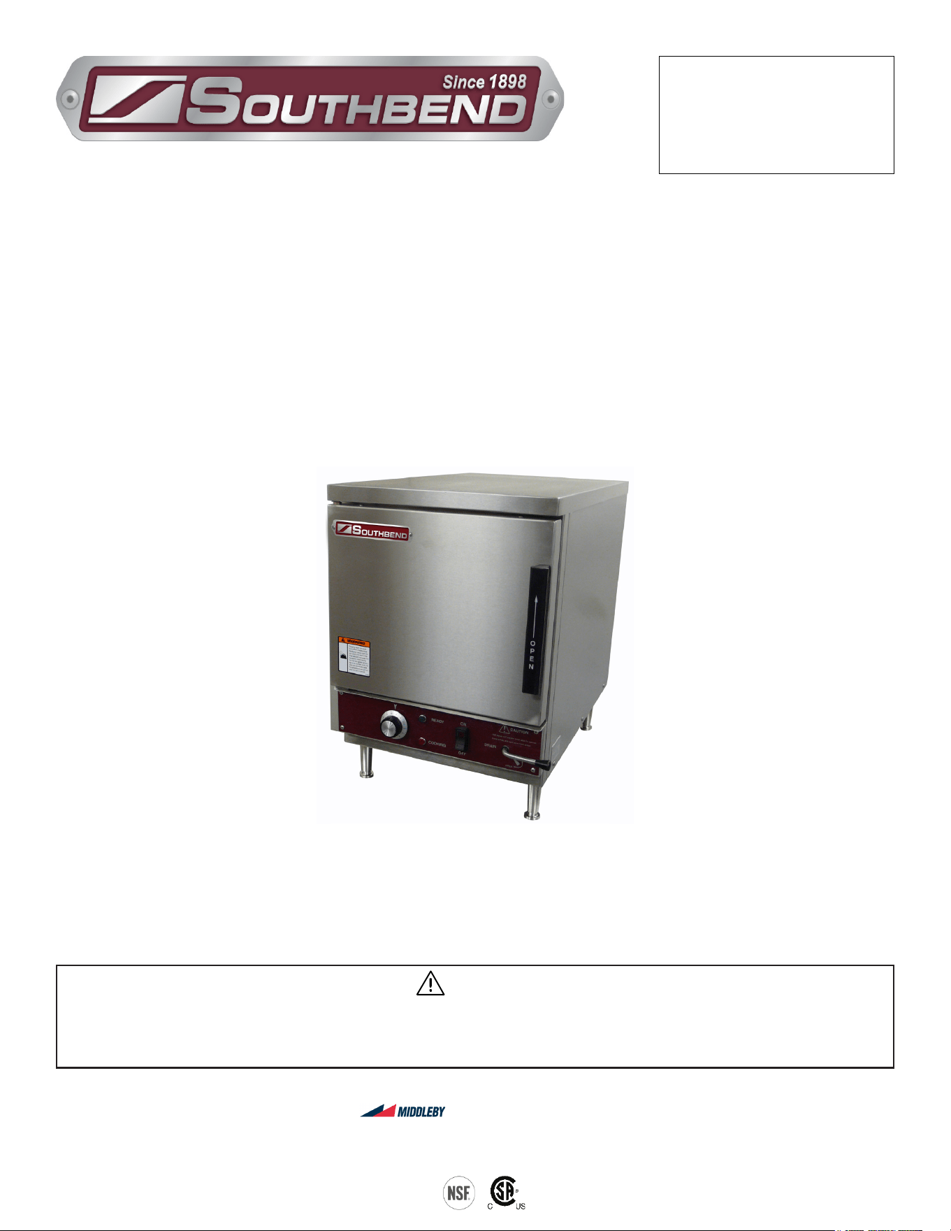
ELECTRIC COUNTER CONVECTION STEAMER
MANUAL SECTION CO
IMPORTANT FOR FUTURE REFERENCE
Please complete this information and retain this
manual for the life of the equipment:
Model #:
___________________________
Serial #:
___________________________
Date Purchased:
_____________________
WARNING
Improper installation, adjustment, alteration, service or maintenance can cause property damage, injury
or death. Read the installation, operating and maintenance instructions thoroughly before installing or
servicing this equipment.
Model R18A-4M
Electric
Counter Convection Steamer
R18A-4M
Installation & Operation Manual
SOUTHBEND STEAM
A Middleby Company
1100 Old Honeycutt Road Fuquay-Varina, North Carolina 27526 USA
www.southbendnc.com
INSTALLATION & OPERATION MANUAL 10272-SB REV 0 (04/22)
PAGE
2
OF 20
Electric Counter Convection Steamer
SAFETY PRECAUTIONS
Before installing and operating this equipment, be sure everyone involved in its operation is fully trained and aware of
precautions. Accidents and problems can be caused by failure to follow fundamental rules and precautions.
The following symbols, found throughout this manual, alert you to potentially dangerous conditions to the operator,
service personnel, or to the equipment.
CAUTION
WARNING
NOTICE
This symbol warns of immediate hazards that will result in severe injury or death.
This symbol refers to a potential hazard or unsafe practice that could result in injury or death.
This symbol refers to a potential hazard or unsafe practice that could result in injury, product
damage, or property damage.
This symbol refers to information that needs special attention or must be fully
understood, even though not dangerous.
DANGER
WARNING
Improper installation, operation, adjustment, alteration, service or maintenance can cause property damage, injury
or death. Read the installation, operating and maintenance instructions thoroughly before installing, operating or
servicing this equipment.
NOTICE
This manual should be retained for future reference.
NOTICE
This product is intended for commercial use only. NOT FOR HOUSEHOLD USE.
Copyright © 2022 by Southbend Steam. All rights reserved. Published in the United States of America.
IMPORTANT NOTES FOR INSTALLATION AND OPERATION
WARNING
This is the safety alert symbol. It is used to alert you to potential personal injury hazards. Obey all safety messages
that follow this symbol to avoid possible injury or death.
Safety Precautions

INSTALLATION & OPERATION MANUAL 10272-SB REV 0 (04/22)
PAGE
3
OF20
Electric Counter Convection Steamer
RETAIN THIS MANUAL FOR FUTURE REFERENCE.
Table of Contents
Important Notes For Installation and Operation .................................................................... 2
Service Connections ............................................................................................................. 4
Installation Instructions ......................................................................................................... 5
Testing Procedures ............................................................................................................... 10
Operation .............................................................................................................................. 11
Cleaning ................................................................................................................................ 15
Cooking Guidelines ............................................................................................................... 13
Maintenance ......................................................................................................................... 20
Adjustment for High Altitude Locations ................................................................................. 22
Troubleshooting .................................................................................................................... 23
Table of Contents
INSTALLATION & OPERATION MANUAL 10272-SB REV 0 (04/22)
PAGE
4
OF 20
Electric Counter Convection Steamer
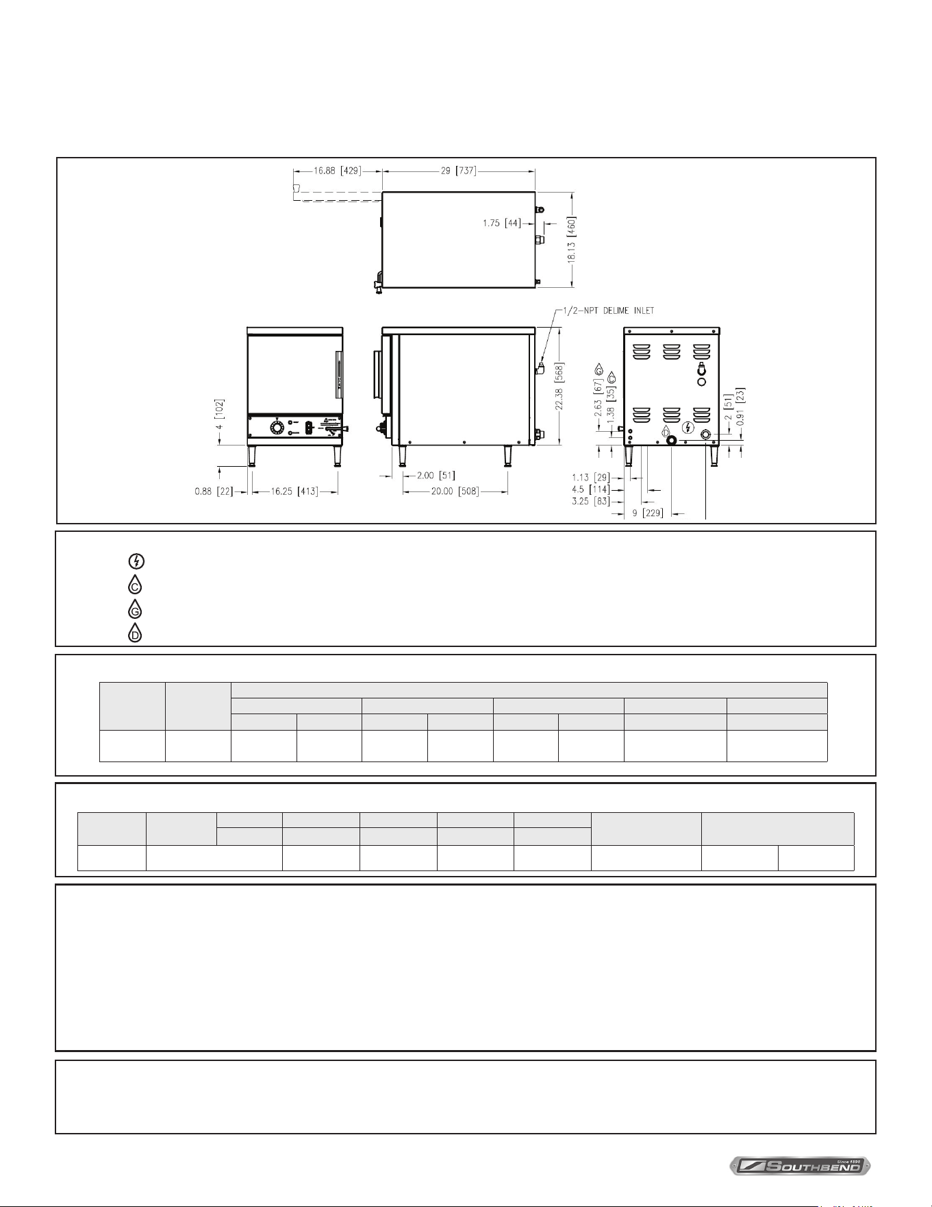
Service Connections
ELECTRICAL CHARACTERISTICS
COMPARTMENT PAN CAPACITY, WEIGHT AND CLEARANCE
SERVICE CONNECTIONS
– ELECTRICAL CONNECTION: ø 1 1/8” hole for electrical connection. Rating to be as specied on data plate.
– COLD WATER: 3/8” (10 mm) O.D. tubing at 25-50 psi (170-345 kPa).
– GENERATOR WATER: 3/8” (10 mm) O.D. tubing at 25-50 psi (170-345 kPa).
– DRAIN: 1” (13 mm) NPT
Model Pan Depth
Inches 1” 2.5” 4” 6”
Shipping Weight Minimum Clearance
MM 25 64 102 152
R18A-4M Total Quantity of Pans 8 4 2 2 155 lbs. [70 kg]
SIDES
BACK
0
0
Terry System Cartridge Changes / Installation – “2-3 gallons of water MUST be purged at each cartridge change or new installation prior to
water supply being fed to the steamer. Failure to do so can result in component damage within the steamer which is not covered under warranty.
For additional guidance on proper installation, refer to install documentation provided with each Terry System and Replacement Cartridge Set.”
DISCLAIMER
WATER QUALITY STATEMENT
Water is the essential ingredient in steam equipment, water quality is the major factor aecting the performance of your appliance. Crown Steam Group oers a
Comprehensive Water Treatment System which exceeds our minimum water requirements. Proof of installation and proper cartridges replacement is required for
warranty coverage. Water supply to Crown Steam Group steamers must be within these guidelines.
Total dissolved solids.......................Less than 60 PPM Chlorine ............................Less than 1.5 PPM
Total alkalinity ........................................ Less than 20 PPM pH Factor .........................6.8 - 7.3
Silica ....................................................... Less than 13 PPM
Water which does not meet these standards should be treated with the installation of Middleby’s Water Treatment System. Call 919-762-1000 if you have questions
concerning your water meeting these parameters.
*Failure or malfunction of this appliance due to poor water quality is not covered under warranty.
Reference www.crownsteamgroup.com for complete warranty details and instructions.
As continued product improvement is a policy of Southbend Steam, specications are subject to change without notice.
Service Connections
Model kW
AMPS/PHASE
208V 220V 240V 380V 8.4kW 415V
1 PH 3 PH 1 PH 3 PH 1 PH 3 PH 3 PH 3 PH
R18A-4M 9 48.1 27.8 38.2 22.1 41.7 24.1 12.8 13.9
INSTALLATION & OPERATION MANUAL 10272-SB REV 0 (04/22)
PAGE
5
OF20
Electric Counter Convection Steamer
The R18A-4M steamer is a single compartment electric pressureless steam cookers with an internal electric steam
generator that maintains water temperature at approximately 205 °F. For voltages 208, 240 and 480 it is rated at 10 kW.
For voltages 220 and 380 it is rated at 8.4 kW.
At high altitude locations a lower temperature is required to achieve atmospheric steaming.
Contact your authorized service oce to have the thermostat adjusted if the steamer will be operated at high altitudes.
Installation
Unpacking
IMMEDIATELY INSPECT FOR SHIPPING DAMAGE
Immediately after unpacking the steamer, check for possible shipping damage. If the steamer is found to be damaged,
save the packaging material and contact the carrier within 15 days of delivery.
Prior to installation, verify that the electrical service agrees with the specications on the machine data plate which is
located on the left side panel.
Installation Instructions
General
Location
Allow space for plumbing and electrical connections. Allow adequate access for operating and servicing the steamer
(36” at the front of the steamer and 15” above the steamer).
4” Adjustable Legs
Thread the four 4” adjustable legs shipped in a box inside the steamer cabinet into the threaded holes on the bottom
corners of the steamer.
Leveling
Using a spirit level, adjust the feet on the adjustable legs to level the steamer front-to-back and side-to-side. After the
drain is connected, check for level by pouring water onto the oor of the compartment. All water should drain through the
opening at the back of the compartment cavity.
Installation
INSTALLATION & OPERATION MANUAL 10272-SB REV 0 (04/22)
PAGE
6
OF 20
Electric Counter Convection Steamer
Anchoring Steamer (Without Legs)
1. Ensure that there is adequate clearance to open the manual drain handle.
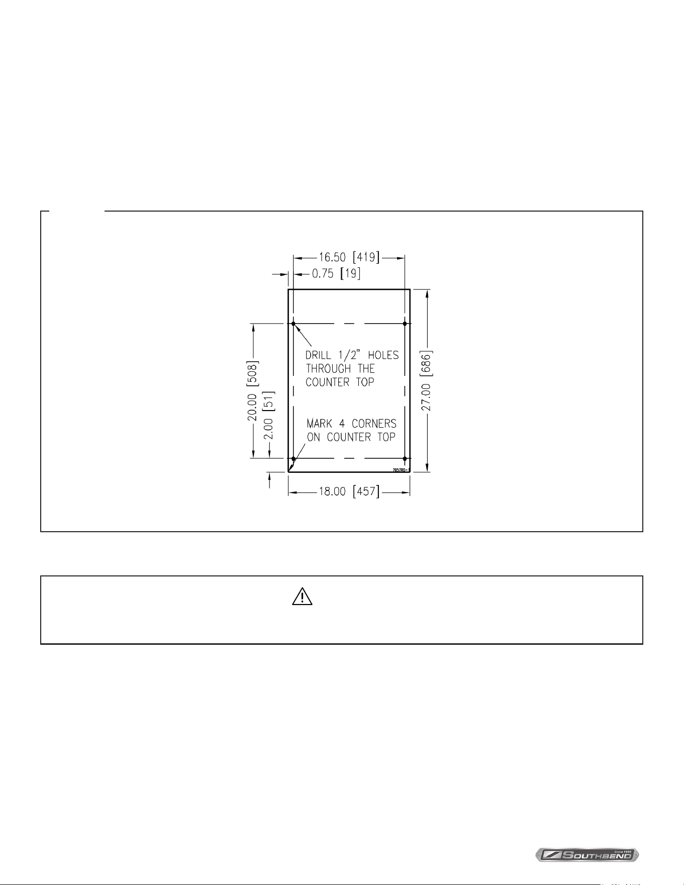
2. Place steamer in the desired location on the levelled counter top and mark four corners. Remove the steamer and drill
1/2” holes as indicated in Figure 1.
3. Apply a bead of RTV or other equivalent sealant around bottom perimeter edge of the steamer. If anchoring the
steamer, this bottom seal is necessary to meet NSF requirements.
4. Set steamer on counter and bolt down securely with 3/8 - 16 bolts (not supplied).
Figure 1
Installation
Connect the water supply lines to the brass compression ttings for 3/8” copper tube. The water lines supply water to the
generator tank and the cooling system where steam is condensed before entering the drain line. Each will be marked to
indicate condensate or generator feed. The condensate feed must be cold water and the boiler feed may be either cold or
hot water. Providing hot water feed to the generator will reduce recovery time during cooking. A manual shuto valve must
be provided convenient to the steamer.
Plumbing Connections
WARNING
Plumbing connections must comply with applicable sanitary, safety and plumbing codes.
INSTALLATION & OPERATION MANUAL 10272-SB REV 0 (04/22)
PAGE
7
OF20
Electric Counter Convection Steamer
CAUTION
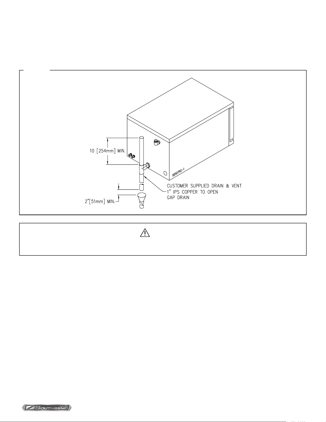
In order to avoid any back pressure in the steamer, do not connect solidly to any drain connection.
Drain Connections (figure 2)
The drain connection (Figure 2) must be 1” IPS down, preferably with one elbow only, maximum length of 2 feet before
open air gap and piped to an open air gap type drain. Drain pipe should be copper. DO NOT use PVC pipe - PVC pipe
may lose its rigidity or glue may fail.
Figure 2
Installation
INSTALLATION & OPERATION MANUAL 10272-SB REV 0 (04/22)
PAGE
8
OF 20
Electric Counter Convection SteamerInstallation
Water Quality
The water supply connected to this steamer should contain no more than 2.0 grains of hardness per gallon with pH from
7.0 to 8.5. This degree of hardness and pH can easily be obtained with the use of a properly maintained water softener.
Water supplies vary from one location to another. A local water treatment specialist should be consulted before installing
any steam generating equipment.
Untreated water contains scale producing minerals which can precipitate onto the surfaces in the boiler. Due to the
temperatures in the boiler, the minerals can bake onto the surfaces and components. This can result in early component
failure and reduced product life.
Mineral scale on components causes several problems:
1. The surfaces of the heating devices become coated with scale, reducing the heat transfer eciency. This can produce
hot spots on the heating elements and result in premature failure.
2. The water level probes become coated with scale. Scale will bridge across the probe insulator from the metal
extension which senses the water level in the boiler cell. Once this scale becomes wet, the water level control is
unable to maintain the proper water level in the boiler. This situation may cause an electric heating element to fail if
the element is not adequately covered by water.
Strainers and lters will NOT remove minerals from the water.
Refer to REMOVAL OF LIME SCALE DEPOSITS, page 20.
Generator Water In
This connection supplies water to the generator that produces steam to cook with. Connect to a potable source of water
with 25 to 50 psi pressure. It is also recommended that a lter assembly designed to prevent scale buildup in the generator
be used and sized appropriately. The generator has a capacity of 1.3 gallons and will consume on average approximately
3.8 gallons per hour during cooking. The rate of ll for the generator is approximately 24 to 34 gallons per hour.
Condenser Water In
This connection supplies water to condense any residual steam from cooking and tempering the drain. This must be
a cold water supply and is not required to be ltered. This water will be consumed at a rate of approximately 24 to 34
gallons per hour during cooking.
Vent Hood
Some local codes may require the steamer to be located under an exhaust hood. Information on the construction and installation
of ventilating hoods may be obtained from Vapor Removal from Cooking Equipment, NFPA standard No. 96 (latest edition).
Electrical Connections
WARNING
Disconnect electrical power supply and place a tag at the disconnect switch to indicate that you are working on the circuit.
Electrical grounding must be provided in accordance with local codes or in the absence of local codes, with the National
Electrical Code, ANSI/NFPA70, or the Canadian Electrical Code, CSA C22-2, as applicable.
Use copper wire suitable for at least 90 degrees Celsius. The steamer must be grounded. The wiring diagram is located
on the right side panel as you face the steamer.
INSTALLATION & OPERATION MANUAL 10272-SB REV 0 (04/22)
PAGE
9
OF20
Electric Counter Convection Steamer Testing Procedures
Testing Procedures
Once the steamer is installed and all mechanical connections have been made, thoroughly test the steamer before
operation.
1. Check that proper water, drain and electrical connections have been made.
2. Ensure the manual drain valve is in the closed position.
3. Turn main power switch ON. After approximately 5 minutes, the READY light should come on, indicating that
the water temperature is 205 degrees Fahrenheit.
4. When the READY light comes on, set timer to the “5 minute” position. With door open, observe that no
steam is entering the compartment and that the COOKING light is OFF.
5. Close compartment door. The COOKING light should now be illuminated and steam should be heard
entering the compartment after about 45 seconds.
6. Check drain line to ensure that water from cold water condenser is flowing through the drain line.
7. Open compartment door and observe that steam supply to chamber is cut off. (READY light should again
come on as COOKING light goes off.)
8. Close compartment door and let cooking cycle finish. When the timer returns to “0” position, a buzzer will
sound signalling the end of the cooking cycle. Buzzer must be manually turned off by setting the timer to its
OFF position.
9. To shut down steamer, turn main power switch OFF, open the manual drain valve and leave compartment
door slightly open.
CAUTION
Live steam and accumulated hot water in the compartment may be released when the door is opened.
INSTALLATION & OPERATION MANUAL 10272-SB REV 0 (04/22)
PAGE
10
OF 20
Electric Counter Convection Steamer
Operation
When set to ON, your steamer has been factory set to maintain the generator standby temperature just below the boiling
point, approximately 205 degrees Fahrenheit, in READY mode.
CONTROLS
Main Power Switch - Standard controls
ON .......................Boiler will automatically ll with water and begin heating to STANDBY temperature.
OFF .....................Unit will be powered o. Always open the manual drain valve to prevent sediment buildup in the boiler.
Ready Light ........When lit, indicates steam generator has reached standby temperature of approximately 205 degrees
Fahrenheit and is ready for the cooking cycle.
Cooking Light ....When lit, indicates that a cooking cycle is in progress.
Timer ..................Set the cooking time (0 to 60 minutes) - steam cooking will begin when the door is closed. The cooking
cycle will be interrupted if the door is opened during the cooking cycle; resume cooking by closing the
door. When done, a buzzer sounds and steam stops being supplied to the cooking chamber. Turn timer
OFF to stop the buzzer.
Preheat
Turn the main power switch ON. When the ready light comes on, set the timer to 1 minute to preheat the compartment.
This should be done when the steamer is rst used for the day or whenever the chamber is cold. The door should be
closed during the preheat cycle.
COOKING light is lit.
When the buzzer sounds, turn the timer to OFF. The steamer is now ready to cook.
Cook
After the preheat cycle, the READY light should be ON.
Place pans of food in the cooking chamber. Close the door. Set the timer. Steam ows into the compartment and the
COOKING light is lit. Opening the door will interrupt cooking; resume by closing the door.
At the end of the cooking cycle, the COOKING light goes o, the buzzer sounds and steam stops being supplied to the
cooking chamber. To stop the buzzer, turn the timer to OFF.
Shutdown
Turn the main power switch OFF – power to the unit will be shut o. Open the manual drain valve to allow sediment in the
generator to be ushed out and prevent scale build up. Leave the compartment door open to allow the inside to dry out.
For an extended shutdown, turn the main power switch OFF, turn power and water supply OFF.
Operation
IMPORTANT
Each compartment is equipped with a removable drain screen. Frequently check the drain screen for
accumulation of food particles. Should food particles accumulate against, or clog the drain screen,
remove it, clean it thoroughly and then replace it in its original position
Frequently check that the compartment drain and plumbing is free of all obstructions. Never place food containers, food or
food portion bags in the cooking compartment in such a way that the compartment drain becomes obstructed.
INSTALLATION & OPERATION MANUAL 10272-SB REV 0 (04/22)
PAGE
11
OF20
Electric Counter Convection Steamer Operation
Constant Steam Feature - optional feature
Operation with this Feature
Operation for Timed Cooking
Use the switch to select “TIMED COOKING”. The operator then must select the time required for the cooking by setting
the timer dial to the desired time from “0 to “60” minutes. At the end of the cook time an audible buzzer will sound.
Operation for Constant Steam
Use the switch to select “CONTINUOUS COOKING”. This mode will provide continuous steam to the cooking chamber
until the operator either turns the selector switch to the “TIMED COOKING” position, or turns the power switch to the
“OFF” position. The steamer will heat to enter into a continuous cooking cycle. Both indicator lights on the selector switch
will be illuminated as well as the COOKING pilot light.
Steam Cooking
Your steamer eciently cooks vegetables or other foods for immediate serving. Steam cooking should be carefully time
controlled. Keep hot-food-holding-time to a minimum to produce the most appetizing results. Prepare small batches, cook
only enough to start serving, then cook additional amounts to meet demand. Separate frozen foods into smaller pieces to
allow more ecient cooking.
Use a pan cover for precooked frozen dishes that cannot be cooked in the covered containers in which they are packed if
they require more than 15 minutes of cooking time. When a cover is used, approximately one-third additional cooking time
is necessary.
Cooking time for frozen foods depends on amount of defrosting required. If time permits, allow frozen foods to partially
thaw overnight in a refrigerator. This will reduce their cooking time.
Preparation
Prepare vegetables, fruits, meats, seafood and poultry normally by cleaning, separating, cutting, removing stems, etc.
Cook root vegetables in a perforated pan unless juices are being saved. Liquids may be collected in a solid 12 inch by 20
inch pan placed under a perforated pan. Perforated pans are used for frankfurters, wieners and similar items when juices
do not need to be preserved. Solid pans are good for cooking puddings, rice and hot breakfast cereals. Vegetables and
fruits are cooked in solid pans to preserve their own juices. Meats and poultry are cooked in solid pans to preserve their
own juices or to retain broth. Canned foods may be heated in their opened cans (cans placed in 12 inch by 20 inch solid
pans) or the contents may be poured into solid pans.
Acceptable Pan Sizes
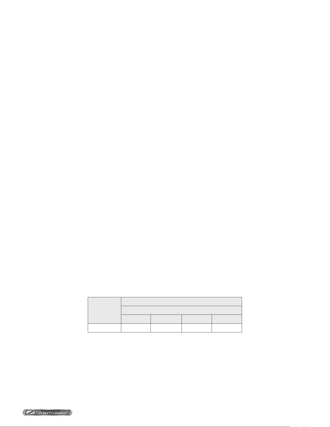
The steamer accommodates combinations of 12” x 20” pans, solid or perforated.
Model
Number of Pans Accommodated
Depth of Pan
1" 2.5” 4” 6”
R18A-4M 8 4 2 2
Draining the Generator
Open the manual valve to drain after each day’s use to ush out minerals and minimize scale build-up in the generator.
INSTALLATION & OPERATION MANUAL 10272-SB REV 0 (04/22)
PAGE
12
OF 20
Electric Counter Convection SteamerCleaning
Cleaning
WARNING
Disconnect the power supply to the appliance before cleaning or servicing.
CAUTION
Do not use cleaning agents that are corrosive.
CAUTION
The appliance and its parts are hot. Use care when operating, cleaning and servicing the appliance.
CAUTION
Live steam and accumulated hot water in the compartment may be released when the door is opened.
CAUTION
An obstructed drain can cause personal injury or property damage.
At the end of each day, or between cooking cycles if necessary:
1. Turn main power switch OFF.
2. Open the manual drain for the generator
3. Remove pans and racks from compartment and wash in sink.
4. Wash compartment interior with clean water.
5. Use warm soapy water with a cloth or sponge to clean exposed bead of door gasket, rinse with warm clear water and
wipe with a dry cloth.
6. Wipe surfaces which touch door gasket with a cloth or sponge and warm soapy water, rinse with warm clear water
and wipe with a dry cloth. Do not apply food oils or petroleum solvents or lubricants directly to door gasket or surfaces
which touch door gasket.
7. Wipe all solids away from drain opening in compartments to prevent clogging.
8. Keep cooking compartment drain working freely. After cooking grease producing foods, operate steam with
compartment empty for 30 minutes at end of the day, or pour 1/2 gallon of warm soapy water down the drain, followed
by 1/2 gallon of warm clear water.
9. Leave door slightly open when steamer is not in use.
Weekly, or more often if necessary:
Clean exterior with a damp cloth and polish with a soft dry cloth. Use a non-abrasive cleaner to remove discolourations.
INSTALLATION & OPERATION MANUAL 10272-SB REV 0 (04/22)
PAGE
13
OF20
Electric Counter Convection Steamer Cooking Guidelines
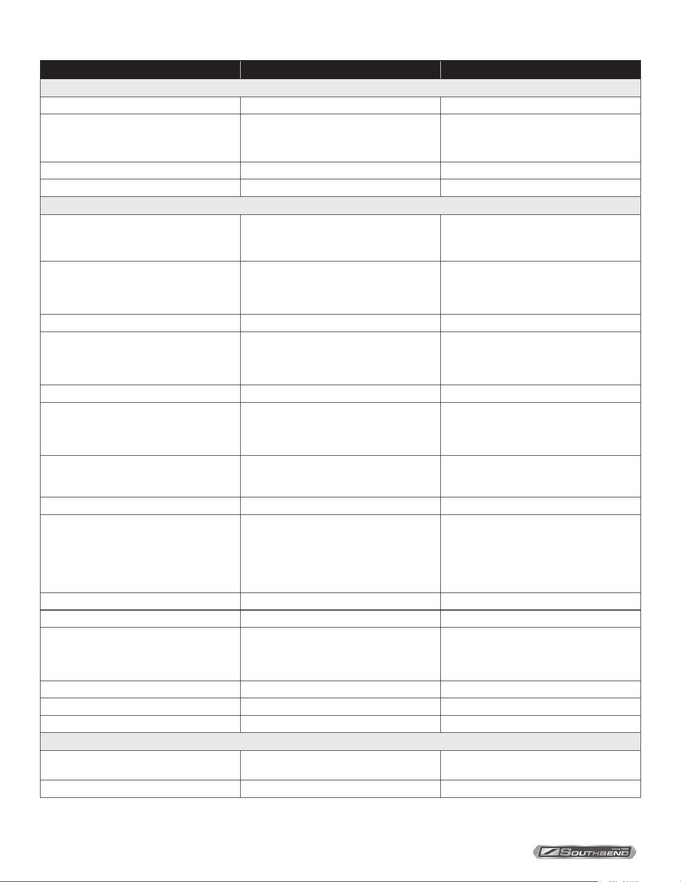
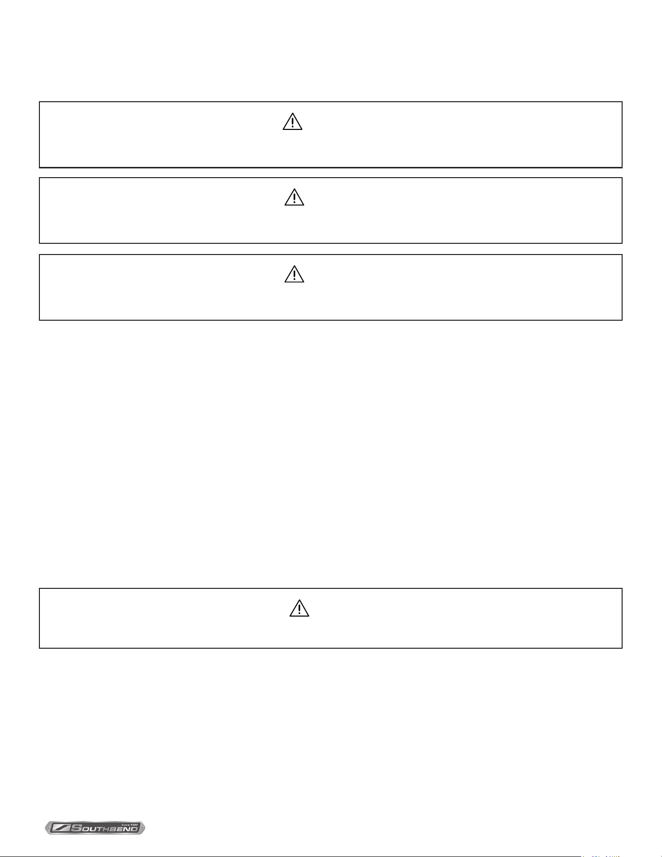
Cooking Guidelines
The steamer steam cooks vegetables, frankfurters, eggs in their shells, and certain other meats or food items at
atmospheric pressure.
These cooking guidelines are suggestions only. You should experiment with your food products to determine the cooking
times that will give you the best results. Variables which aect cooking time include size, weight, thickness of foods,
temperature, density, previous condition of the foods (fresh, pre-blanched or frozen) and degree of doneness desired.
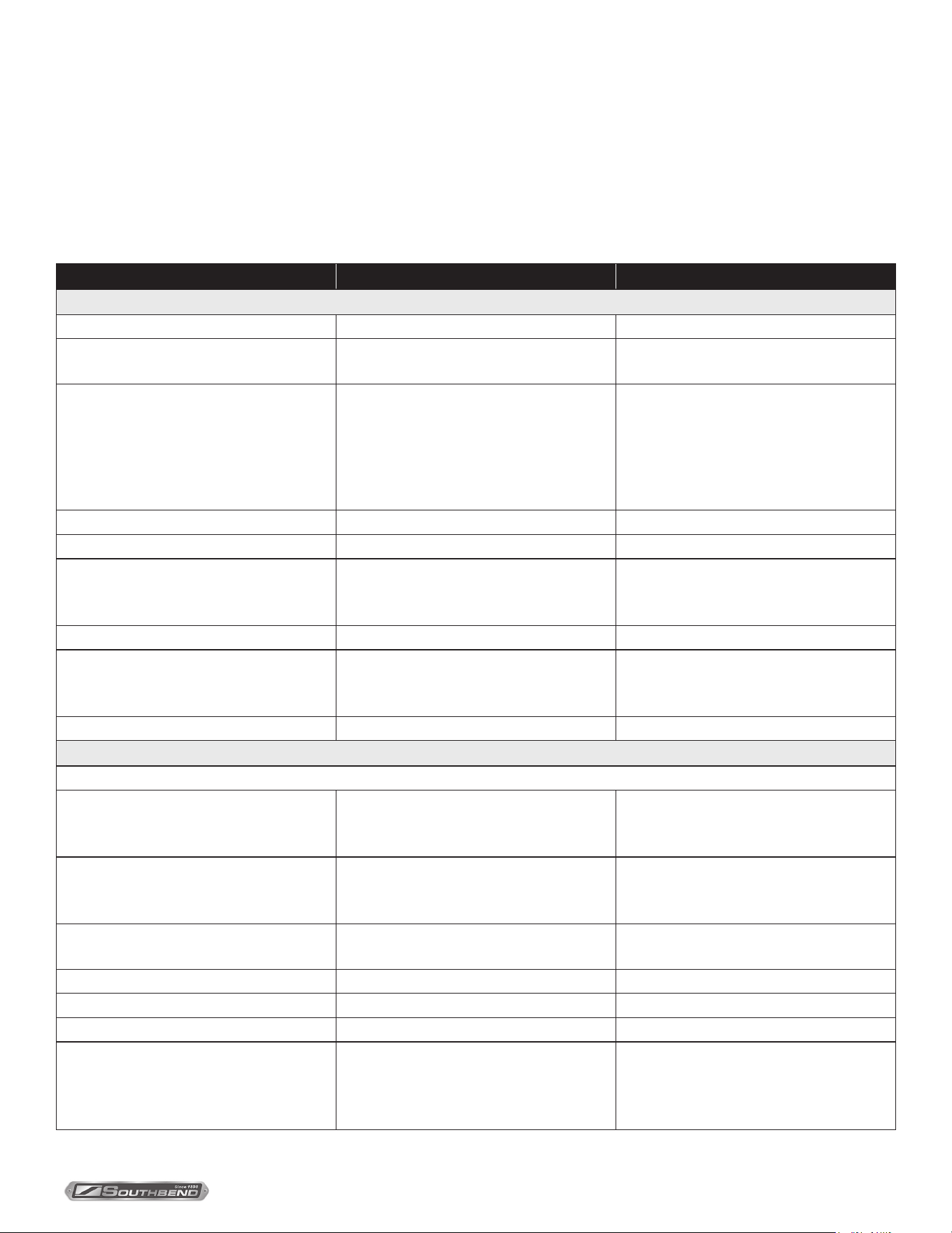
PRODUCT TIME (MINUTES) WEIGHT PER PAN
COOK IN SOLID PANS
Eggs, Scrambled 10 - 12 8 Dozen
Rice, Long Grain
(Cover with 4 cups water per pound.)
25 2 lb.
Pasta (Place perforated pan inside solid
pan,cover pasta with cold water.)
Spaghetti, Regular/Vermicelli
Macaroni, Shells/Elbows
Noodles, 1/2” Wide
Lasagna Noodles
12 - 15
15 - 18
12 - 15
15 - 18
Frozen Casseroles, Lasagna 35 Full Pan
Meat Loaf, 3 - 5 pounds each 40 15 lb.
Beef
Ground Chuck
Sliced as Purchased
20 - 25
35 - 40
10 lb.
10 lb.
Shrimp, Frozen, 10 per pound 5 4 lb.
Beans
Baked
Refried
9
9
10 lb. Can
10 lb. Can
Prunes, Dried 12 to 15
COOK IN PERFORATED PANS
SEAFOOD
Clams
Frozen
Fresh, Cherrystone
10 - 12
5 - 6
3 Doz.
3 Doz.
King Crab, Frozen
Claws
Legs
4
4 - 6
2-1/2 lb.
4-1/2 lb.
Lobster Tail, Frozen
Lobster, Live, 10 - 12”
6
5
10 lb.
4 Per Pan
Salmon Fillets, Frozen, 8 ounces each 5 7-1/2 lb.
Scallops, Fresh 4 3 lb.
Scrod Fillets, Fresh 3 - 5 4 lb.
Eggs
Hard Cooked
Soft Cooked
Soft Yolk for Caesar Salad
15
9 - 10
6 - 8
4 Doz.
4 Doz.
4 Doz.
INSTALLATION & OPERATION MANUAL 10272-SB REV 0 (04/22)
PAGE
14
OF 20
Electric Counter Convection Steamer
PRODUCT TIME (MINUTES) WEIGHT PER PAN
COOK IN PERFORATED PANS (Continued)
Chicken - Breasts, Legs, Thighs 20 15 lb.
Turkey, Frozen
Breasts (2)
Cut Lengthwise
90
55
6 - 7 lb. Each
20 - 25 lb.
Corned Beef 40 - 75 6 - 8 lb.
Hot Dogs or Wieners 3 80 - 100 Count
VEGETABLES
Asparagus Spears
Frozen
Fresh
10 - 12
5
3 Doz.
5 lb.
Beans
Green, 2” Cut, Frozen/Fresh
Lima, Frozen
Baby Lima, Frozen
6
8
5
5 lb.
5 lb.
5 lb.
Brussel Sprouts, Frozen 6 5 lb.
Broccoli
Spears, Frozen
Spears, Fresh
Florets, Frozen
8
6
6
4 lb.
5 lb.
5 lb.
Cabbage, Fresh, 1/6 Cut 8 5 lb.
Carrots
Baby Whole, Frozen
Crinkle Cut, Frozen
Sliced, Fresh
8
7 - 8
11
7 lb.
4 lb.
9 lb.
Cauliower, Florets
Frozen
Fresh
6
7 - 8
4 lb.
5 lb.
Celery, 1” Diagonal Cut 7 5 lb.
Corn
Yellow Whole Kernel, Frozen
Cobbettes, Frozen
Corn-On-Cob, Fresh
5
8
16 - 18
10 - 12
16 - 18
5 lb.
27 Ears
80 Ears
18 Ears
54 Ears
Peas, Green 6 5 lb.
Potatoes, Whole Russet 55 40 lb.
Spinach
Chopped, Frozen
Defrosted
Fresh Cut
17
5
3
6 lb.
6 lb.
2 lb.
Squash, Acorn Halves 25 10 Halves
Zucchini, Slices 8 10 lb.
Frozen Mixed Vegetables 6 - 7 5 lb.
FRUIT
Fruit, Blanch for Peeling,
Grapefruit, Oranges
3
Pineapple, Whole for Cutting 4
Cooking Guidelines
INSTALLATION & OPERATION MANUAL 10272-SB REV 0 (04/22)
PAGE
15
OF20
Electric Counter Convection Steamer
Maintenance
COLD WATER CONDENSER
The steamer is equipped with a cold water condenser in the rear of the cooking chamber which helps to condense the
steam prior to discharge into the drain. The steamer freely vents itself by the negative pressure created by the condensate
water drainage. This negative pressure prevents steam leakage around the door gasket and helps draw the steam
through the cooking compartment. Steam leakage at the door may indicate a plugged or improperly installed drain.
Removal of Scale Deposits
It is recommended that your steamer be delimed once a month, or more often if necessary.
Should your steamer develop a heavy buildup of lime scale deposits, use CLR.
Before beginning deliming procedures, ensure that water is not overowing into the cooking compartment.
The generator tank has a removable sealed tank cover. The main purpose of the removable cover is for inspection of
the interior of the tank for lime build up and easy removal of large pieces of lime that will not ush out drain. Should the
tank cover have to be removed, check condition of sealing gasket before replacing cover. The hold down bolts are to be
tightened to 160 inch pound torque each.
WARNING
Disconnect the power supply to the appliance before cleaning or servicing.
CAUTION
Live steam and accumulated hot water in the compartment may be released when the door is opened.
CAUTION
The appliance and its parts are hot. Use care when operating, cleaning and servicing the appliance.
NOTICE
Contact the factory, the factory representative or local service company to perform maintenance and repairs.
Maintenance
INSTALLATION & OPERATION MANUAL 10272-SB REV 0 (04/22)
PAGE
16
OF 20
Electric Counter Convection Steamer
Removal of Scale Deposits (continued)
Maintenance
WARNING
Read and follow instructions on the CLR bottle. Use plastic or rubber gloves to avoid skin contact. If CLR comes in
contact with skin, rinse with clean water.
1. Set the power switch to OFF and drain steam generator by opening the manual drain valve.
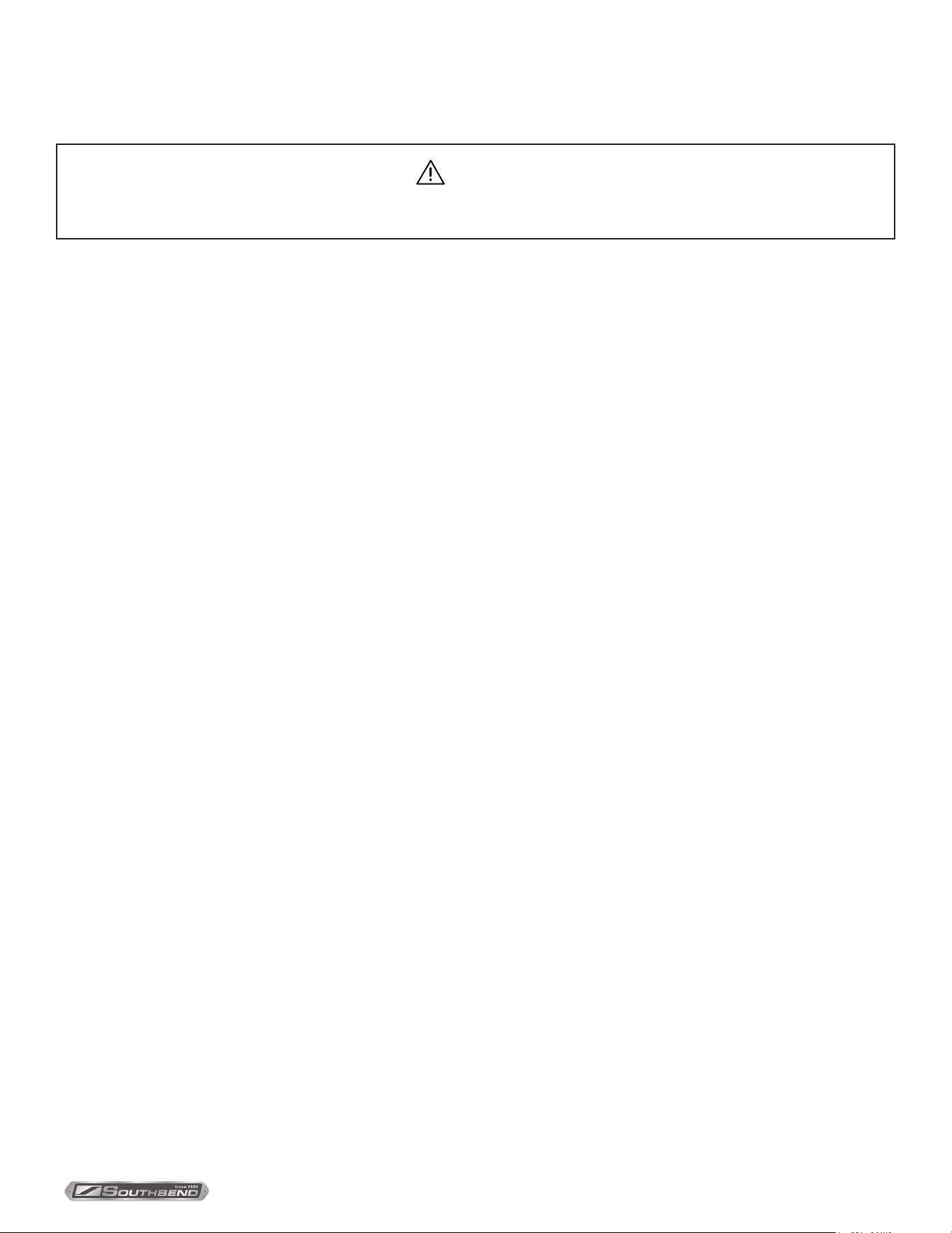
2. Delime port (A) is located on left side at the rear of the unit. Close the manual drain valve and unscrew hex plug from
elbow to allow CLR solution to be poured in using a tube and funnel. Pour in 28 ounces of solution into the generator
(pour slowly to avoid spillage). Remove tube and funnel.
3. Screw the hex plug back into the elbow so that it is sealed.
4. Turn power switch to ON and set the timer to OFF.
5. Allow steamer to remain in READY cycle for 1-1/2 hours, then turn power switch OFF and open the manual drain
valve to allow generator to completely empty.
6. FLUSH CYCLE: Close the manual drain valve and turn the power switch ON. When the READY light comes on, turn
power switch to OFF and open the manual drain valve to allow generator to completely empty. Repeat these steps
three times to completely ush generator.
7. Clean exterior and interior. Use a mild solution of soap and water. Rinse with clean cloth. Dry with soft cloth. Leave
compartment door open when not in use.
The steamer is now ready for use. Turn o for overnight shutdown.
INSTALLATION & OPERATION MANUAL 10272-SB REV 0 (04/22)
PAGE
17
OF20
Electric Counter Convection Steamer Adjustment for High Altitude Locations
Adjustment for High Altitude Locations
NOTICE
Contact the factory, the factory representative or local service company to perform maintenance and repairs.
The steamer has been factory set so that when it is ON and in the READY mode, it will maintain water temperature in the
steam generator tank at approximately 205 degrees Fahrenheit (just below water boiling point). However, for high altitude
locations, an authorized servicer must adjust the steamer temperature lower. To adjust:
1. Close the manual drain valve and remove side panel and turn control panel power switch to ON.
2. Open compartment door, and after about 5 minutes, steam will be seen, entering the cooking compartment.
3. Turn thermostat shaft counterclockwise to lower temperature until steam just ceases to enter cooking compartment
and READY light goes on.
4. Replace side panel.
5. Follow TESTING PROCEDURES in this manual.

INSTALLATION & OPERATION MANUAL 10272-SB REV 0 (04/22)
PAGE
18
OF 20
Electric Counter Convection SteamerTroubleshooting
Troubleshooting
Water Flows into Drain during Shutdown
When steamer is shut down and cold water is running continuously into the open drain, either or both solenoid valves did
not close when steamer was turned o.
1. Disassemble solenoid valve(s) and examine for scale or foreign particles lodged in diaphragm or core tube.
2. Clean valve(s) thoroughly and reassemble, or replace valve(s).
Water Overflows into Cooking Compartment
When steamer is rst turned on for the day, and the following conditions occur:
- READY light does not come on after about 5 minutes,
- Water begins to overow into cooking compartment,
- Water ll solenoid valve is open,
Any or all of these symptoms may indicate a problem with the operating probe due to either:
1. A short between the operating probe terminal and body of the steamer. Call your authorized servicer.
2. Excessive scale build-up on the operating probe. This acts as an “insulation” and prevents the probe from sensing the
water level. It is therefore unable to close the water ll (solenoid) valve to shut o the water.
As a temporary solution, with power OFF, unscrew probes, check visually, and clean or chip o scalant. Replace
probe.
This problem is an indication of severe harmful water conditions which should be corrected immediately to avoid
damage to the components and ultimate malfunction of the steamer. (See WATER QUALITY in this manual).
Heater Elements Do Not Come On
When the steamer is turned ON and heater elements do not activate, and the READY light does not come on, then the
contactor may be burned out. If a considerable amount of “chattering” of contactor has been previously experienced,
then the thermostat bulb may be coated with scalant and unable to sense water temperature in the boiler accurately, and
therefore unable to control the contactors.
1. Replace contactor.
2. Unscrew thermostat bulb, clean o scalants and screw thermostat bulb back in.
This problem may be an indication of inadequate water quality and is not covered under warranty. Have water quality
analyzed and corrected immediately to avoid complete malfunction of the steamer.
Unit Shuts Down while in Operation
1. Pressure switch has been activated due to 5 psi (34 kPa) pressure in the generator tank.
2. Pressure in the generator tank is caused by plugged steam jet tubes or steam diverters due to scale or poor water
conditions.
3. Steam jet tubes/steam diverter will have to be cleaned or replaced.

INSTALLATION & OPERATION MANUAL 10272-SB REV 0 (04/22)
PAGE
19
OF20
Electric Counter Convection Steamer
Notes
INSTALLATION & OPERATION MANUAL 10272-SB REV 0 (04/22)
PAGE
20
OF 20
Electric Counter Convection Steamer
R18A-4M
Electric
Counter Convection Steamer
A product with the Southbend Steam name incorporates the best in durability and low maintenance. We all recognize,
however, that replacement parts and occasional professional service may be necessary to extend the useful life of this
appliance. When service is needed, contact a Southbend Steam Authorized Service Agency, or your dealer. To avoid
confusion, always refer to the model number, serial number, and type of your appliance.
SOUTHBEND STEAM
A Middleby Company
1100 Old Honeycutt Road Fuquay-Varina, North Carolina 27526 USA
www.southbendnc.com