User Manual
Bedienungsanleitung
de
en
2-channel amplied subwoofer module with DSP
2-Kanal Subwoofer-Verstärkermodul mit DSP
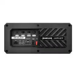
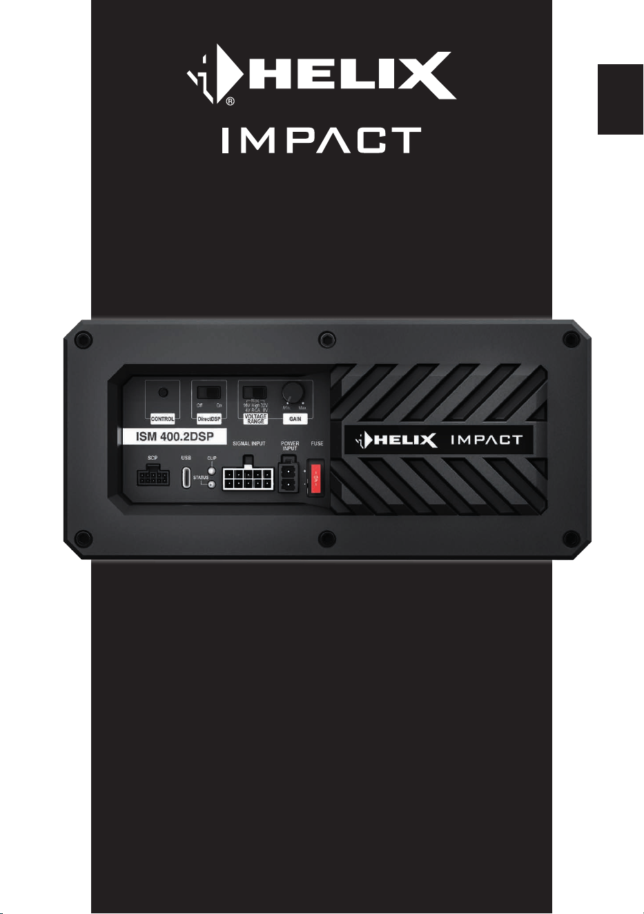
ISM 400.2DSP

2
Sehr geehrter Kunde,
wir gratulieren Ihnen zum Kauf des HELIX IMPACT
ISM 400.2DSP, einem hochwertigen Subwoofer-
Verstärkermodul mit integriertem DSP.
Das ISM 400.2DSP basiert auf unserer mehr
als 35-jährigen Erfahrung in der Forschung und
Entwicklung von Audiokomponenten.
Es wurde nach den neuesten technischen
Erkenntnissen entwickelt und zeichnet sich durch
eine hochwertige Verarbeitung sowie den Einsatz
ausgereifter Technologien aus.
Viel Freude an diesem Produkt wünscht Ihnen das
Team von
AUDIOTEC FISCHER
Allgemeines zum Einbau von HELIX-
Komponenten
Um alle Funktionen des IMPACT Subwoofer
Moduls (ISM) optimal nutzen zu können, lesen
Sie diese Bedienungsanleitung sorgfältig durch,
bevor Sie mit der Installation und Inbetriebnahme
beginnen.
Jedes Verstärkermodul wurde vor dem Versand
auf einwandfreie Funktion geprüft, um höchste
Qualität und Zuverlässigkeit sicherzustellen.
Wir empfehlen Ihnen, die Installation von einem
Einbauspezialisten durchführen zu lassen, da
der Nachweis eines fachgerechten Einbaus und
Anschlusses des Gerätes Voraussetzung für die
Garantieleistungen sind.
• Achten Sie bei der Befestigung darauf, dass
Schrauben oder Werkzeuge keine Gehäuse-
bauteile oder den Subwoofer selbst beschädi-
gen
• Stellen Sie sicher, dass das ISM plan auf der
Montageäche auiegt und vibrationsfrei befe-
stigt wird
• Verlegen Sie alle Kabel so, dass sie nicht einge-
klemmt oder übermäßig gebogen werden
• Setzen Sie das Gerät keiner Feuchtigkeit oder
Nässe aus
Wichtiger Hinweis: Unsachgemäßer Einbau
oder fehlerhafte Verkabelung können zu Schäden
am Verstärkermodul oder am Subwoofer führen.
Eine fachgerechte Installation ist daher zwingend
erforderlich.
Allgemeines zum Anschluss des HELIX
IMPACT ISM 400.2DSP Verstärkermoduls
Das Modul darf nur in Kraftfahrzeuge eingebaut
werden, die den 12 V-Minuspol an Masse haben.
Bei anderen Systemen können das Modul und die
elektrische Anlage des Kfz beschädigt werden.
Die Plusleitung für die gesamte Anlage sollte in
einem Abstand von max. 30 cm von der Batterie
mit einer Hauptsicherung abgesichert werden.
Der Wert der Sicherung errechnet sich aus der
maximalen Stromaufnahme der Car-Hi Anlage
und dem verwendeten Leitungsquerschnitt.
Verwenden Sie zum Anschluss des Verstär-
kermoduls an die Stromversorgung des Fahr-
zeugs ausschließlich geeignete Kabel mit aus-
reichendem Kabelquerschnitt. Die Sicherung
des ISM 400.2DSP darf nur mit dem gleichen
Wert (40 A) ersetzt werden, um eine Beschädi-
gung des Gerätes zu verhindern. Höhere Werte
können zu gefährlichen Folgeschäden führen!
Die Kabelverbindungen müssen so verlegt sein,
dass keine Klemm-, Quetsch- oder Bruchgefahr
besteht. Bei scharfen Kanten (Blechdurchfüh-
rungen) müssen alle Kabel gegen Durchscheuern
gepolstert sein. Ferner darf das Versorgungskabel
niemals mit Zuleitungen zu Vorrichtungen des Kfz
(Lüftermotoren, Brandkontrollmodulen, Benzinlei-
tungen etc.) verlegt werden.
Herzlichen Glückwunsch!
Allgemeine Hinweise
3
de
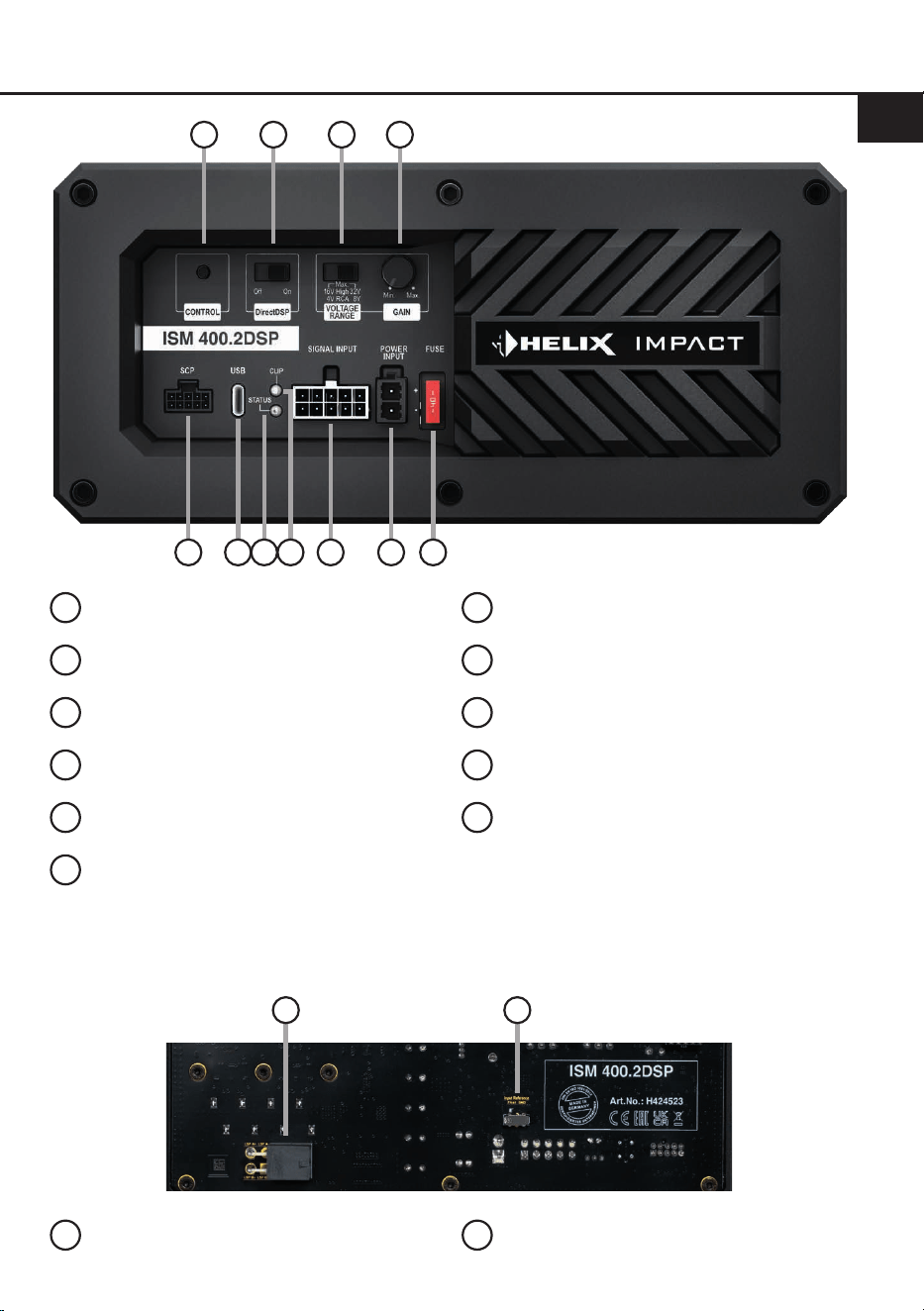
Anschluss- und Bedienelemente
1
Control Taster
Seite 12, Punkt 4
2
DirectDSP-Schalter
Seite 7, Punkt 2
3
Eingangsspannungsbereichs-Schalter
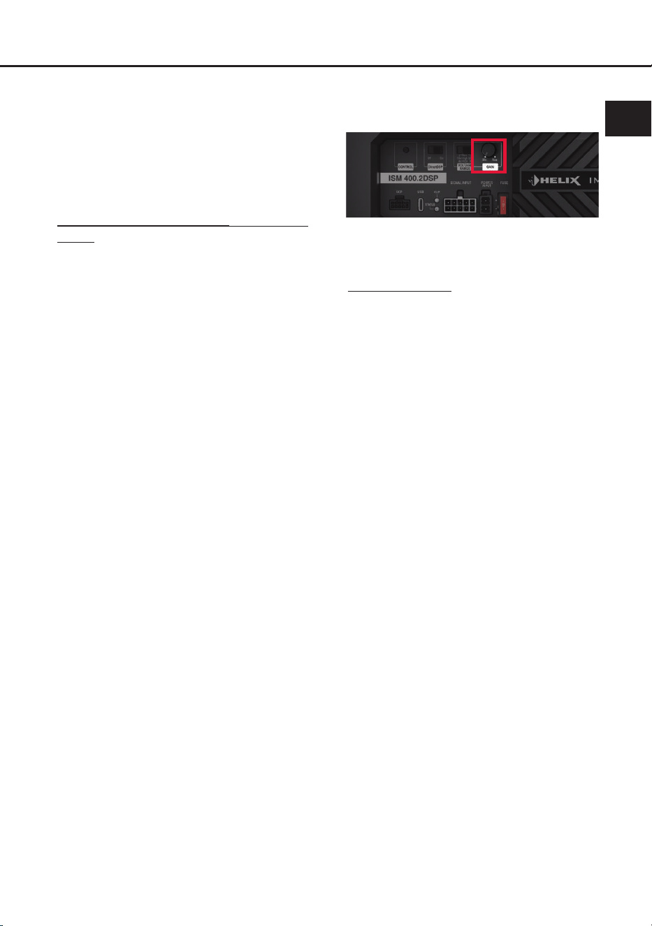
Seite 7, Punkt 1
4
Gain-Regler
Seite 9, Punkt 8
5
SCP (Smart Control Port)
Seite 12, Punkt 2
6
USB-Eingang
Seite 9, Punkt 7
7
Status LED
Seite 12, Punkt 1
8
Clipping LED
Seite 12, Punkt 3
9
Signaleingänge
Seite 8, Punkt 3 - 5
10
Anschluss Stromversorgung
Seite 9, Punkt 6
11
Sicherung
Seite 14
1
3
2 4
5 76 109 118
12 13
Rückseite ISM 400.2DSP
12
Lautsprecherausgänge
Seite 5 unten
13
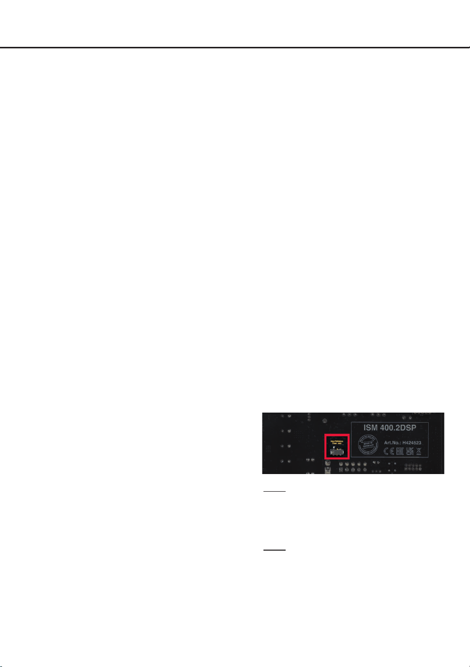
Masseschalter
Seite 11, Punkt 12
4
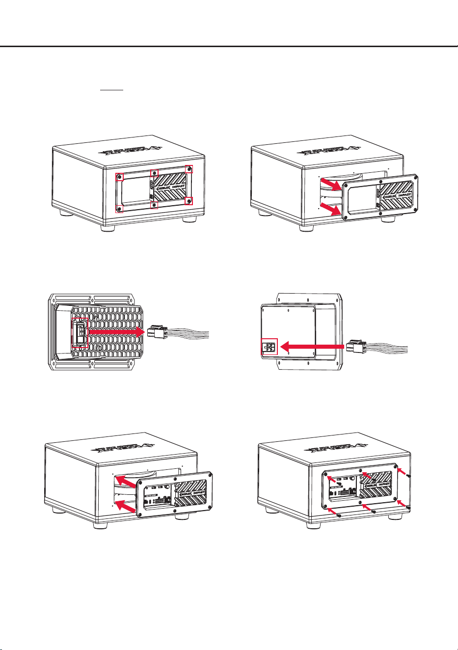
Einbau & Installation
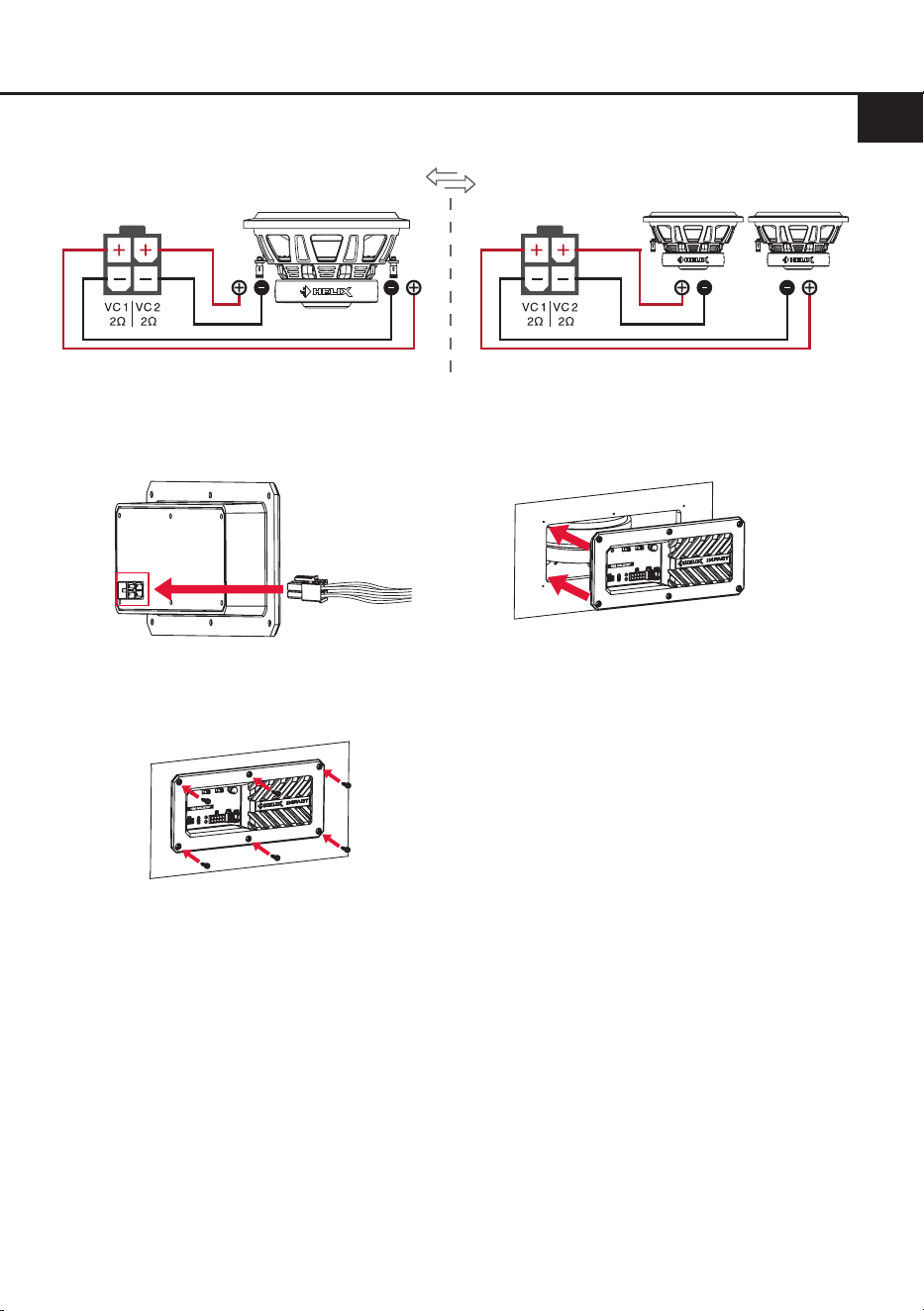
Das HELIX IMPACT ISM 400.2DSP ist ein kompaktes Verstärkermodul, das einen passiven 2 x 2 Ohm
Subwoofer in einen aktiven verwandelt. Es kann als Upgrade für das passive Anschluss-Terminal in
HELIX IMPACT DVC2 Gehäusesubwoofern eingesetzt oder als Grundlage für den Aufbau eines eige-
nen aktiven Subwoofers verwendet werden.
1. Upgrade für das passive Anschluss-Terminal eines HELIX IMPACT DVC2 Gehäusesubwoofers
i. Verschraubungen des passiven Anschluss-
terminals lösen
ii. Terminal vorsichtig nach vorne herausziehen
v. ISM 400.2DSP in das Gehäuse einsetzen vi. ISM 400.2DSP mit den zuvor demontierten Schrauben
des passiven Anschlussterminals befestigen
iii. Kabelverbindung auf der Rückseite des passiven
Anschlussterminals lösen
iv. Anschlusskabel des Subwooferchassis mit
ISM 400.2DSP Modul verbinden
Vom
Subwooferchassis
Rückansicht
Vom
Subwooferchassis
Rückansicht
5
de
2. Universeller Einbau für den Aufbau eines aktiven Subwoofers
i. Lautsprecher-Anschlusskabel des ISM 400.2DSP (Seite 6, Abb. 2) mit Lautsprecherchassis verbinden.
Minimale Gesamtimpedanz 2 x 2 Ohm.
iii. ISM 400.2DSP in Montageönung setzen
iv. ISM 400.2DSP mit den mitgelieferten Schrauben
im Gehäuse verschrauben
Molex Lautsprecher
Anschlusskabel
Frontansicht
VC2 VC1
ii. Lautsprecher-Anschlusskabel mit ISM 400.2DSP
Modul verbinden
Vom
Subwooferchassis
Rückansicht
Hinweis zum Anschluss der Lautsprecherausgänge
Schließen Sie die Lautsprecherausgänge (Seite 3, Punkt 12) ausschließlich über das mitgelieferte An-
schlusskabel mit dem 4-poligen Stecker und den oenen Kabel enden (Seite 6, Abb. 2) an. Das bei-
liegende Anschlusskabel muss für den Anschluss der Lautsprecher fachgerecht verlängert werden.
Verwenden Sie hierfür geeignete Lautsprecherkabel und stellen Sie eine dauerhaft sichere elektrische
Verbindung her.
Achten Sie darauf, dass alle Verbindungen phasenrichtig angeschlossen sind, d.h. Plus zu Plus und
Minus zu Minus. Vertauschen von Plus und Minus hat einen Totalverlust der Basswiedergabe zur Folge.
Der Pluspol ist bei den meisten Lautsprechern gekennzeichnet.
Die Impedanz pro Kanal darf 2 Ohm nicht unterschreiten, da sonst die Schutzschaltung des Verstärker-
moduls aktiviert wird.
Molex Lautsprecher
Anschlusskabel
Frontansicht
Lautsprecherimpedanz
2 x 2 Ω 1 x 2 Ω 1 x 2 Ω
Lautsprecherimpedanz
ODER

6
Hardware-Konguration
Abb. 1: Pinbelegung des Signaleingangs (Signal Input)
Signal Input
1. Highlevel-Lautsprechereingang links (+)
2. Highlevel-Lautsprechereingang rechts (+)
3. Vorverstärker-Eingang links (RCA)
4. Vorverstärker-Eingang rechts (RCA)
5. Remote-Eingang
6. Highlevel-Lautsprechereingang links (-)
7. Highlevel-Lautsprechereingang rechts (-)
8. Vorverstärker-Masse (RCA)
9. AISA-Masse
10. AISA-Signalausgang
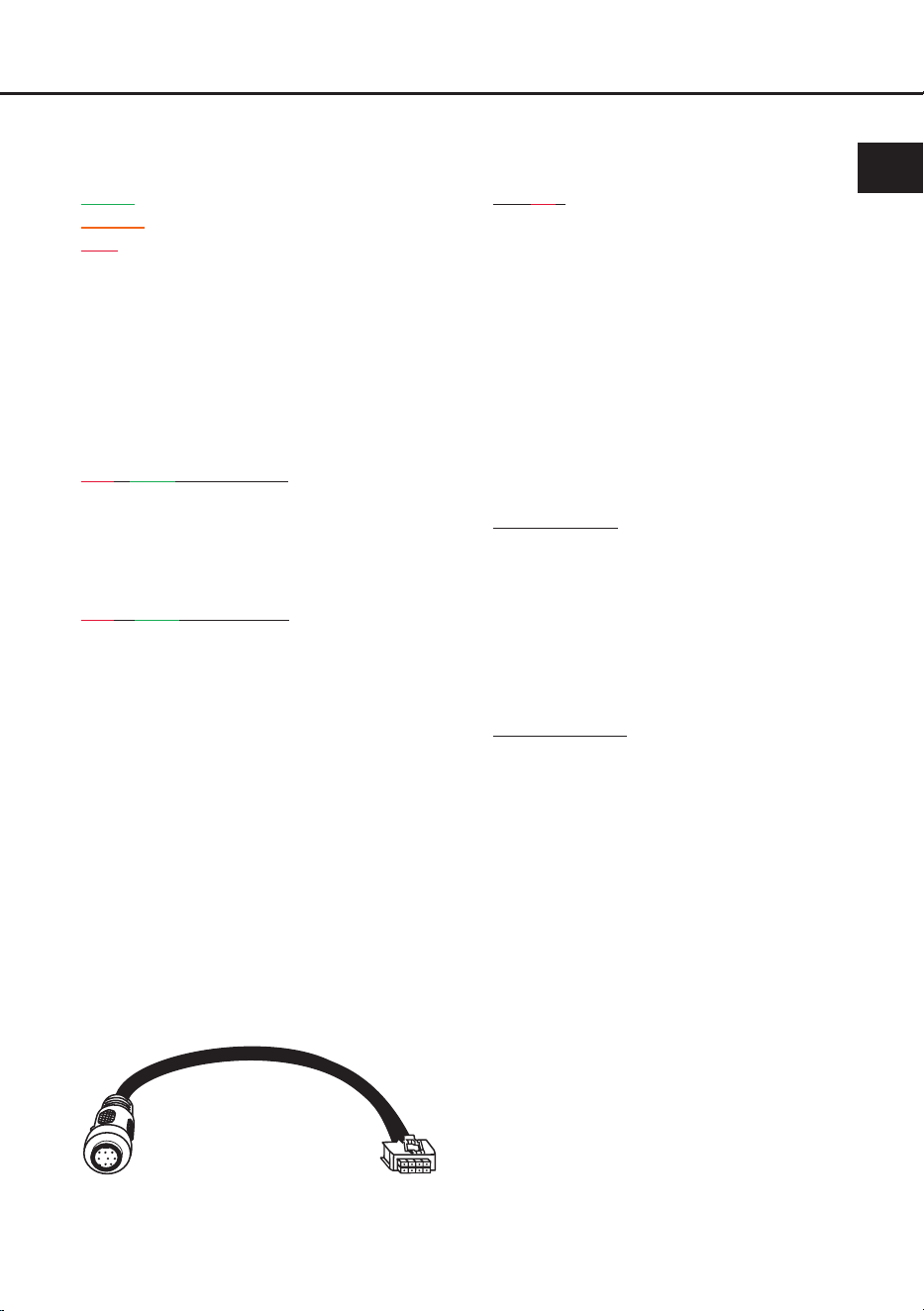
Abb. 2: Übersicht Anschlusskabel
1
2
Anschlusskabel Stromversorgung (Power Input)
Anschlusskabel Signaleingang (Signal Input
)
Lautsprecher-Anschlusskabel
1
2
109876
54321
3
3

7
de
Nachdem Sie das Verstärkermodul eingebaut
und mit dem / den Subwoofer(n) verbunden
haben, kongurieren Sie das HELIX IMPACT
ISM 400.2DSP in der nachfolgenden
Reihenfolge
Achtung: Für die Durchführung der nachfol-
genden Schritte werden Spezialwerkzeuge und
Fachwissen benötigt. Um Anschlussfehler und
Beschädigungen zu vermeiden, fragen Sie im
Zweifelsfall Ihren Einbauspezialisten und beach-
ten Sie zwingend die allgemeinen Anschluss- und
Einbauhinweise (siehe Seite 2).
1. Einstellung des Eingangsspannungs-
bereichs und der Eingangsimpedanz
(ADEP.3) der analogen Signaleingänge
WICHTIG: Diese Einstellung muss zwingend
vor der ersten Inbetriebnahme vorgenommen
werden, um Schäden am Verstärkermodul
oder dem angeschlossenen Soundsystem zu
vermeiden.
Die analogen Eingangskanäle des Ver-
stärkermoduls können entweder mit Low-
level- (Cinch / RCA) oder Highlevel- Signalen
(Lautsprecherleitungen) des Steuergeräts
angesteuert werden. Um eine optimale
Signal qualität sicherzustellen, muss der Ein-
gangsspannungsbereich und die Impedanz
(ADEP.3) des Eingangs mit dem Eingangs-
spannungsbereichs-Schalter (Voltage Ran-
ge / Seite 3, Punkt 3) entsprechend des ver-
wendeten Signaltyps eingestellt werden.
Wir empfehlen, die maximale Ausgangsspan-
nung der Signalquelle mithilfe eines geeig-
neten Messgeräts zu ermitteln oder sich an
Ihren autorisierten HELIX Fachhändler zu
wenden. Wenn Sie unsicher sind, empfehlen
wir, die rechte Schalterposition (RCA 8 V /
High 32 V) einzustellen, um mögliche Schä-
den am Gerät zu vermeiden.
Schalterstellung links (16 V / 4 V):
Wählen Sie diese Einstellung für Standardan-
wendungen wie den Anschluss von:
- Audiotec Fischer DSP-Verstärkern über
Cinch-Kabel
- Original-Radios
- Aftermarket-Radios mit maximal 4 V RMS
Ausgangsspannung
Der Eingangsspannungsbereich liegt hier zwi-
schen 0,4 und 4 Volt für den Lowlevel-Vorver-
stärkereingang sowie 1,6 und 16 Volt für den
Highlevel-Lautsprechereingang.
Schalterstellung rechts (32 V / 8 V):
Wählen Sie diese Einstellung, wenn Sie Ge-
räte aus den folgenden Kategorien anschlie-
ßen:
- Aftermarket-Radios mit mehr als 4 V RMS
Ausgangsspannung
- Premium Soundsystem-Verstärker mit
mehr als 50 W RMS Ausgangsleistung
- Stand-Alone DSPs mit mehr als 4 V RMS
Ausgangsspannung
Der Eingangsspannungsbereich liegt hier zwi-
schen 0,8 und 8 Volt für den Lowlevel-Vorver-
stärkereingang sowie 3,2 und 32 Volt für den
Highlevel-Lautsprechereingang.
2. Einstellen des DirectDSP-Schalters
Das ISM 400.2DSP verfügt über einen
DirectDSP-Schalter, mit dem festgelegt wird,
wie das Eingangssignal verarbeitet wird.
Werkseitig steht der Schalter auf „O“, sodass
der integrierte DSP aktiv ist und das Verstär-
kermodul wie vorgesehen mit dem DSP PC-
Tool konguriert werden kann.
O (werkseitig): Das Eingangssignal wird
durch den internen DSP verarbeitet. Für Stan-
dardanwendungen – etwa den Anschluss
direkt an ein Radio oder eine andere Signal-
quelle ohne DSP – muss diese Einstellung
gewählt werden. Die Filtereinstellungen wie
Hochpass, Subsonic oder Tiefpass müssen in
diesem Fall vollständig über das DSP PC-Tool
vorgenommen werden.
On: Der interne DSP ist deaktiviert. Das Ein-
gangssignal wird ungeltert an den Lautspre-
cherausgang weitergeleitet.
Wichtig: Diese Einstellung sollte nur gewählt
werden, wenn in einem vorgeschalteten DSP
oder DSP-Verstärker alle notwendigen Über-
nahmefrequenzen für Hochpass, Subsonic
bzw. Tiefpass eingestellt sind.

8
Hardware-Konguration
3. Anschluss der Lowlevel-Vorverstärkerein-
gänge
Die Lowlevel-Vorverstärkereingänge des
Signaleingangs (Signal Input) können über
das beiliegende Anschlusskabel (Seite 6,
Abb.2) und entsprechenden Kabeln an den
RCA / Cinch-Ausgang der Signalquelle (bspw.
Radio / DSP / DSP-Verstärker) angeschlos-
sen werden. Dabei müssen nicht beide Ein-
gänge belegt werden. Wird nur ein Kanal be-
legt, empfehlen wir den linken Eingangskanal
zu verwenden.
Die Eingangsempndlichkeit kann mit Hilfe
des Gain-Reglers und der Clipping LED op-
timal an die Signalquelle angepasst werden
(Seite 3, Punkt 4 & 8).
Die Einschaltautomatik (Auto Remote) des
Verstärkers funktioniert bei Verwendung der
Vorverstärkereingänge nicht, sodass der
Remote-Eingang (Remote IN) des Signalein-
gangs (Signal Input) zwingend belegt werden
muss.
Achtung: Die Vorverstärkereingänge und die
Highlevel-Lautsprechereingänge dürfen nicht
gleichzeitig genutzt werden, da dies zu Schä-
den am Soundsystem führen kann.
4. Anschluss der Highlevel-Lautsprecherein-
gänge
Die Highlevel-Lautsprechereingänge des
Signal eingangs (Signal Input) können über
das beiliegende Anschlusskabel (Seite 6,
Abb. 2) direkt mit den Lautsprecherausgän-
gen der Signalquelle (z. B. Radio oder DSP-
Verstärker) verbunden werden.
Dabei empfehlen wir folgende Kanalbelegung:
Stereo-Signalquelle
Bei einer Stereo-Signalquelle sind beide High-
level-Lautsprechereingänge (links und rechts)
des ISM 400.2DSP zu verwenden.
Mono-Signalquelle
Bei einer Mono-Signalquelle ist das Signal
ausschließlich am linken Highlevel-Lautspre-
chereingang anzuschließen.
Achten Sie bitte auf eine korrekte Polung!
Wenn Sie einen Anschluss verpolen, kann
dadurch die Funktion des Verstärkermoduls
beeinträchtigt werden.
Die Eingangsempndlichkeit kann mit Hilfe
des Gain-Reglers und der Clipping LED op-
timal an die Signalquelle angepasst werden
(Seite 3, Punkt 4 & 8).
Der Highlevel-Lautsprechereingang verfügt
über den ADEP.3-Schaltkreis (Advanced Dia-
gnostics Error Protection der 3. Generation).
Dieser sorgt dafür, dass das Verstärkermodul
vom OEM-Radio als Lautsprecher erkannt
wird. Dadurch werden keine Funktionen im
Werksradio deaktiviert und es erfolgt kein Ein-
trag im Fehlerspeicher des Fahrzeugs.
Der linke Highlevel-Lautsprechereingang ist
zusätzlich mit einer Signalerkennung aus-
gestattet. Bei Verwendung dieses Eingangs
schaltet das Verstärkermodul bei allen han-
delsüblichen Radios und Verstärkersignalen
automatisch ein. Ein Einschalten über den
Remote-Eingang des Signaleingangs (Remo-
te IN) ist somit nicht erforderlich.
Achtung: Verwenden Sie zum Anschluss
ausschließlich das mitgelieferte Anschlusska-
bel ( Seite 6, Abb. 2).
Achtung: Die Highlevel-Lautsprecherein-
gänge und die Vorverstärkereingänge dürfen
nicht gleichzeitig genutzt werden, da dies zu
Schäden am Soundsystem führen kann.
5. Anschluss des Remote-Eingangs
Der Remote-Eingang dient zum Ein- und
Ausschalten des ISM 400.2DSP, wenn die
Vorverstärker-Eingänge des Signaleingangs
(Signal Input) genutzt werden.
Dazu muss
der Remote-Eingang des Verstärkermoduls
mit dem Remote-Ausgang der unmittelbar
vorgeschalteten Komponente (Nachrüstra-
dio, DSP oder DSP-Verstärker), welche das
Eingangssignal für das ISM 400.2DSP liefert,
verbunden werden. Es wird dringend davon
abgeraten, den Remote-Eingang des Verstär-
kermoduls über das Zündungsplus des Fahr-
zeugs zu steuern, um Störgeräusche beim
Ein- und Ausschalten zu vermeiden.
Hinweis: Dieser Eingang muss nicht belegt
werden, wenn der linke Highlevel-Lautspre-
chereingang des Signaleingangs benutzt wird.
Hinweis: Schließen Sie den Remote-Eingang
(Remote IN) ausschließlich über das mitge-
lieferte Anschlusskabel des Signaleingangs
(Seite 6, Abb.2) an.
9
de
6. Anschluss der Stromversorgung
ACHTUNG: Vor dem Anschluss des +12 V
Versorgungskabels an das Bordnetz muss die
Autobatterie abgeklemmt werden.
Schließen Sie die Stromversorgung aus-
schließlich über das mitgelieferte Power Input
Anschlusskabel (Seite 6, Abb. 2) an. Achten
Sie unbedingt auf eine korrekte Polarität.
+12 V (gelbes Kabel): Das +12 V Stromkabel
ist am Pluspol der Batterie anzuschließen.
Die Plusleitung sollte in einem Abstand von
max. 30 cm von der Batterie mit einer Haupt-
sicherung abgesichert werden. Der Wert der
Sicherung errechnet sich aus der maximalen
Stromaufnahme der gesamten Car-Hi Anla-
ge (ISM 400.2DSP = max. 45 A bei 12 V Bord-
netz). Verwenden Sie bei kurzen Leitungen
(< 1 m) einen Querschnitt von mindestens
6 mm². Bei längeren Leitungen empfehlen wir
einen Querschnitt von 10 mm² bis 16 mm².
GND (schwarzes Kabel): Anschluss für die
Masseleitung. Das Massekabel muss an einer
nicht isolierten Stelle mit dem Kfz-Chassis ver-
bunden werden. Der Kabelquerschnitt sollte
den gleichen Durchmesser wie die Plusleitung
haben. Ein nicht ausreichender Massekontakt
führt zu unerwünschten Störgeräuschen und
Fehlfunktionen.
7. Anschluss an den Computer & Einschalten
Das Verstärkermodul kann über den USB-C-
Eingang (Seite 3, Punkt 6) mit dem Computer
verbunden und anschließend mit dem DSP
PC-Tool konguriert werden. Verwenden Sie
dazu das beiliegende USB-Kabel.
Bevor Sie das ISM 400.2DSP das erste Mal mit
einem Computer verbinden, laden Sie die ak
-
tuellste DSP PC-Tool Software (mindestens
Version 6) von unserer Homepage herunter.
Es
ist ratsam, regelmäßig nach Updates der Soft-
ware zu schauen, damit das Gerät immer auf
dem aktuellsten Stand ist. Die Software sowie
eine umfangreiche Knowledge Base nden
Sie auf www.audiotec-scher.com.
Es wird dringend empfohlen, die DSP PC-Tool
Knowledge Base vor der ersten Benutzung
durchzulesen, um Komplikationen und Fehler
zu vermeiden.
Wichtig: Stellen Sie sicher, dass das
ISM 400.2DSP bei der ersten Installation der
Software noch nicht am PC angeschlossen
ist. Verbinden Sie diesen erst, wenn die Soft-
ware samt der USB-Treiber vollständig instal-
liert ist.
Im folgenden Abschnitt lesen Sie die wich-
tigsten Schritte zum Anschluss und der ersten
Inbetriebnahme:
1. Laden Sie die DSP PC-Tool Software unter
www.audiotec-scher.com herunter und
installieren Sie diese auf ihrem Computer.
2. Schließen Sie danach das Verstärkermodul
mit dem beiliegenden USB-Kabel an den
Computer an. Wenn Sie längere Distanzen
zu überbrücken haben, verwenden Sie bitte
eine aktive USB-Verlängerung mit integrier-
tem Repeater.
3. Schalten Sie erst das ISM 400.2DSP ein
und starten Sie anschließend die Software.
Sofern die Betriebssoftware des Verstär-
kermoduls nicht mehr aktuell ist, wird diese
automatisch aktualisiert.
8. Einstellung der Eingangsempndlichkeit
der analogen Signaleingänge
ACHTUNG: Es ist zwingend notwendig, die
Eingangsempndlichkeit des ISM 400.2DSP
an die Signalquelle anzupassen, um eine
bestmögliche Signalqualität zu garantie-
ren und Schäden am Verstärkermodul zu
vermeiden.
Außerdem ist es zuvor zwingend erforderlich
den Eingangsspannungsbereich und die Ein
-
gangsimpedanz (ADEP.3) des Signaleingangs
an die Ausgangsspannung Ihrer Signalquelle
anzupassen (Seite 7, Punkt 1).
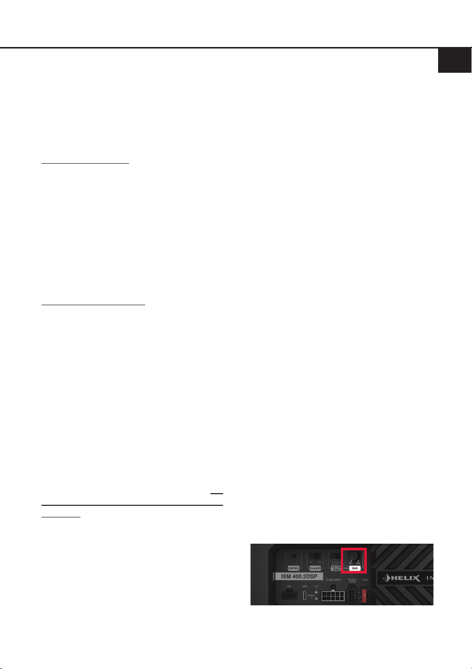
Mit dem Gain-Regler (Seite 3, Punkt 4) kann
die Eingangsempndlichkeit optimal ange-
passt werden. Dieser Regler beeinusst so-
wohl die Highlevel- als auch die Vorverstär-
ker-Eingänge.
Der Regler ist kein Lautstärkeregler, sondern
dient nur der Anpassung.

10
Hardware-Konguration
Regelbereiche:
Schalterstellung links:
Highlevel: 1,6 - 16 Volt
RCA (Cinch): 0,4 - 4 Volt
Schalterstellung rechts:
Highlevel: 3,2 - 32 Volt
RCA (Cinch): 0,8 - 8 Volt
Werkseitig ist die Eingangsempndlichkeit auf
max. 16 Volt (Highlevel) bzw. 4 Volt (RCA)
voreingestellt. In den meisten Fällen ist dies
die optimale Einstellung.
Sollte die Signalquelle eine niedrigere Aus-
gangsspannung liefern, kann die Eingangs-
empndlichkeit angehoben werden.
Liefert die Signalquelle eine höhere Aus-
gangsspannung, beispielsweise im Falle
eines vorgeschalteten OEM / Werksverstär-
kers, muss die Eingangsempndlichkeit zwin-
gend abgesenkt und die korrekte Stellung des
Eingangsspannungsbereichs-Schalters über-
prüft werden (Seite 7, Punkt 1).
Wenn Sie sich hinsichtlich der Ausgangsspan-
nung nicht sicher sind, wenden Sie sich bitte
an Ihren HELIX Fachhändler.
Die Clipping LED (Seite 3, Punkt 8) dient da-
bei als Kontrollinstrument.
Achtung: Es wird dringend empfohlen, die
Signalausgänge des ISM 400.2DSP in der
DSP PC-Tool Software zu muten, da andern-
falls Zerstörungsgefahr für die Lautsprecher
besteht.
Vorgehensweise zur Einstellung der Ein-
gangsempndlichkeit:
1. Stellen Sie sicher, dass der Eingangsspan-
nungsbereich und die Eingangsimpedanz
(ADEP.3) der analogen Signaleingänge
korrekt an die Signalquelle angepasst wur-
den (Seite 7, Punkt 1). Diese Einstellung
muss vor der Anpassung der Eingangs-
empndlichkeit abgeschlossen sein.
2. Verbinden Sie das Verstärkermodul mit
einem Computer und starten Sie die DSP
PC-Tool Software (Seite 9, Punkt 7). Muten
Sie anschließend die Lautsprecheraus-
gänge des Moduls in der Software.
3. Drehen Sie die Lautstärke Ihres Radios auf
90 % der Gesamtlautstärke und spielen Sie
ein geeignetes Testsignal, idealerweise un-
ser speziell dafür entwickeltes „IGS - Input
Gain Setup“ Signal, welches Sie unter den
„Audio Test Tracks“ des DSP PC-Tools n-
den oder auch auf www.audiotec-scher.de
downloaden können.
4. In der Regel ist die Clipping LED aus und
leuchtet nur auf, wenn einer der analogen
Signaleingänge übersteuert wird.
Erhöhen Sie die Eingangsempndlichkeit
durch Rechtsdrehung bis die Clipping LED
aueuchtet.
5. Drehen Sie nun den Gain-Regler gegen
den Uhrzeigersinn bis die Clipping LED
wieder erlischt.
9. Konguration des internen DSPs
WICHTIG: Die Konguration des internen
DSPs ist nur erforderlich, wenn der Direct-
DSP-Schalter auf „O“ steht und kein vorge-
schalteter DSP oder DSP-Verstärker verwen-
det wird. In diesem Fall übernimmt der interne
DSP des ISM 400.2DSP die vollständige
Signalverarbeitung.
Vor der ersten Inbetriebnahme wird dringend
empfohlen, die grundlegenden Einstellungen
des Verstärkermoduls mit der DSP PC-Tool
Software vorzunehmen, um Beschädigungen
an den angeschlossenen Lautsprechern zu
vermeiden.
Nach dem Anschluss an einen PC können Sie
das Verstärkermodul frei in der DSP PC-Tool
Software kongurieren. Nützliche Hinweise
zur korrekten Einstellung entnehmen Sie un-
serer Knowledge Base, welche auf unserer
Webseite bereit steht.
Achtung: Es wird dringend empfohlen, zu
Beginn die Lautstärke am Radio auf Mini-
mum zu drehen und die Signalausgänge des
ISM 400.2DSP in der Software zu muten, da
sonst Zerstörungsgefahr für die Lautsprecher
besteht.
11
10. Optional: Eingangssignal analysieren
Bei Verwendung des Highlevel-Eingangs
empfehlen wir, das Eingangssignal mit Hilfe
des Advanced Input Signal Analyzers (AISA)
der DSP PC-Tool Software auf werkseitig ein-
gestelltes Equalizing, Laufzeitkorrektur und
Allpass-Filter zu überprüfen und ggf. zu kor-
rigieren.
Das ISM 400.2DSP verfügt hierfür über einen
AISA- Signalausgang (Seite 6, Abb. 1) am
10-poligen Anschlussstecker des Signalein-
gangs (Signal Input). Über diesen Ausgang
kann das Eingangssignal für Analysezwecke
an geeignetes Messequipment, wie zum Bei-
spiel das Audiotec Fischer AMI, ausgegeben
werden.
Weitere Informationen zum AISA nden Sie in
der umfangreichen Knowledge Base unserer
Webseite www.audiotec-scher.com.
11. Sound Tuning
Nun können Sie Ihr Sound Setup erstellen.
Informationen rund um das Sound Tuning n-
den Sie in unserer umfangreichen Knowledge
Base auf www.audiotec-scher.com oder
kontaktieren Sie Ihren HELIX Fachhändler vor
Ort.
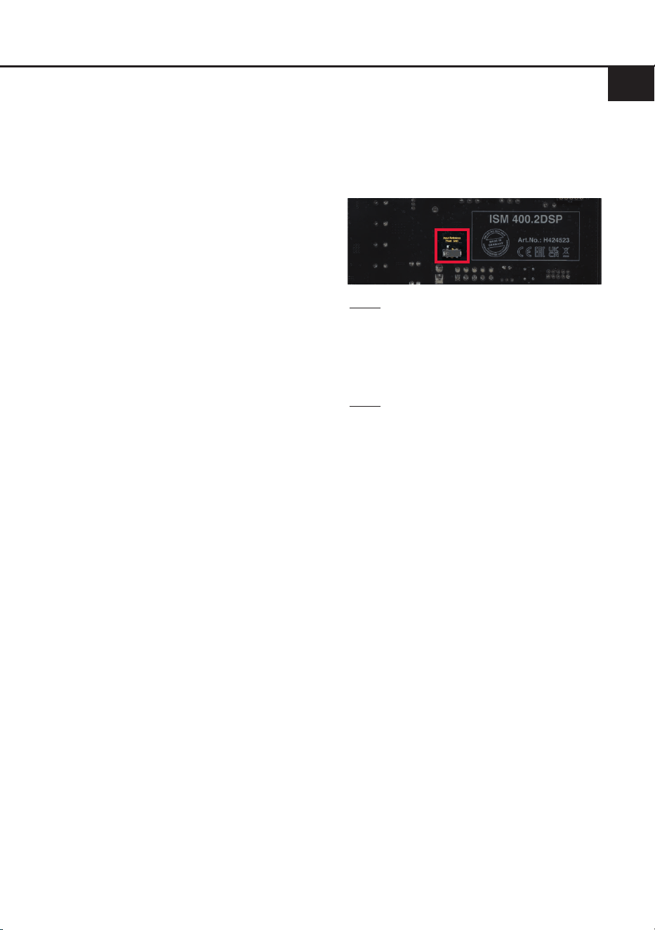
12. Optional: Konguration der Masseanbin-
dung
In bestimmten Fällen kann es zu Störge-
räuschen kommen und notwendig sein, die
Signalmasse der Signaleingänge anzupas-
sen. Dies geschieht über den Masseschalter
auf der Rückseite des Moduls.
Float: In dieser Schalterstellung wird die
Signalmasse durch einen Dierenzverstärker
von der Bordnetzmasse getrennt.
Dies ist in den meisten Fahrzeugen die opti-
male Einstellung, um Störgeräusche, wie z. B.
von der Lichtmaschine, zu vermeiden.
GND: Die Signalmasse des Eingangs wird di-
rekt mit der Bordnetzmasse verbunden. Diese
Einstellung sollte gewählt werden, wenn bei
der Schalterstellung „Float“ Störgeräusche
auftreten.
de

12
1. Status LED
Die Status LED zeigt den Betriebszustand des
Verstärkermoduls und dessen Speichers an.
Grün: Verstärkermodul eingeschaltet und be
-
triebsbereit.
Orange: Power Save Modus aktiv.
Rot: Protection Mode aktiv. Dieser kann un
-
terschiedliche Ursachen haben. Das Verstär-
kermodul ist mit Schutzschaltungen gegen
Über- und Unterspannung sowie Überhitzung
ausgestattet. Prüfen Sie in diesem Fall alle
Anschlüsse auf Fehler, wie z.B. Kurzschlüsse
oder fehlerhafte Verbindungen. Ist die Sicher
-
heitsschaltung der Temperaturüberwachung
aktiv, wird der Remote-Ausgang sowie die
Signalausgabe abgeschaltet, bis ein sicherer
Betrieb wieder gewährleistet werden kann.
Rot / grün langsam blinkend: Keine Betriebs
-
software auf dem DSP installiert. Verbinden
Sie das Verstärkermodul mit der DSP PC-Tool
Software und bestätigen Sie das automatische
Update der Betriebssoftware. Die aktuellste
Version des DSP PC-Tools nden Sie auf
www.audiotec-scher.com.
Rot / grün schnell blinkend: Aktuell ausgewähl
-
ter Sound Setup-Speicherplatz ist leer. Ein
neues DSP Setup muss über die DSP PC-Tool
Software eingespielt werden oder schalten
Sie auf einen Speicherplatz mit vorhandenem
Sound Setup um.
2. SCP (Smart Control Port)
Dieser Multifunktionseingang (Seite 3, Punkt 5)
dient zum Anschluss von HELIX Zubehörpro
-
dukten, wie beispielsweise einer Fernbedie-
nung, mit deren Hilfe diverse Funktionen des
Verstärkermoduls gesteuert werden können.
Die Funktionalität muss je nach Typ der Fern
-
bedienung zuerst im „Remote Control“-Menü
der DSP PC-Tool Software oder an der Fern
-
bedienung selbst konguriert werden.
Achtung: Sofern das Zubehörprodukt keinen
NanoFit Stecker besitzt, ist ein SCP-to-Control
Input Adapter (Art-Nr. M141313) optional bei
Ihrem Fachhändler erhältlich.
3. Clipping LED
In der Regel ist die LED aus und leuchtet nur
auf, wenn einer der analogen Signaleingänge
übersteuert wird.
An (rot): Einer der analogen Signaleingänge
wird übersteuert. Senken Sie die Eingangs
-
empndlichkeit mit Hilfe des Gain-Reglers ab,
bis die LED erlischt. Wie Sie die Eingangs
-
empndlichkeit absenken, ist auf Seite 9 unter
Punkt 8 nachzulesen.
4. Control Taster
Das ISM 400.2DSP bietet 10 interne Speicher
-
plätze für Sound Setups. Mit Hilfe des Control
Tasters lässt sich zwischen zwei Speicherplät
-
zen umschalten. Diese können im DSP PC-
Tool festgelegt werden. Zudem kann durch
langes Drücken des Tasters ein Geräte-Reset
durchgeführt werden.
1. Setup-Wechsel: Taster 1 Sek. drücken.
Werkseitig sind die Speicherbereiche eins und
zwei eingestellt. Der Umschaltvorgang wird
durch einmaliges rotes Blinken der Status LED
angezeigt. Alternativ kann zur Umschaltung
die optionale Fernbedienung URC.3 verwen
-
det werden. Um zwischen allen internen Spei-
cherplätzen umschalten zu können, ist optio-
nales Zubehör, wie z.B. die Fernbedienungen
DIRECTOR und CONDUCTOR notwendig.
2. Geräte-Reset: Taster länger als 5 Sek. ge
-
drückt halten. Durch ein Geräte-Reset wird
der interne Speicher auf die Werkseinstellung
zurückgesetzt! Dies wird durch ein durchge
-
hendes rotes Leuchten und grünes schnelles
Dauerblinken der Status LED angezeigt.
Achtung: Nach dem Resetten des Gerätes
kann das ISM 400.2DSP keine Audio signale
mehr wiedergeben, bis das Gerät mit Hilfe des
DSP PC-Tools geupdated wurde.
SCP-to-Control Input Adapter
Weitere Funktionen
13
de
An das ISM 400.2DSP kann über den SCP (Smart
Control Port / Seite 3, Punkt 5) eine optionale
Fernbedienung, wie die HELIX URC.1 oder
URC.3, angeschlossen werden. Damit lassen
sich Funktionen wie die Subwoofer-Lautstärke
oder ein Setup-Wechsel bequem vom Fahrersitz
aus steuern. Damit eine Fernbedienung genutzt
werden kann, müssen folgende Voraussetzungen
erfüllt sein:
- Der DirectDSP-Schalter (Seite 3, Punkt 2) muss
auf „O“ stehen, sodass der interne DSP akti-
viert ist.
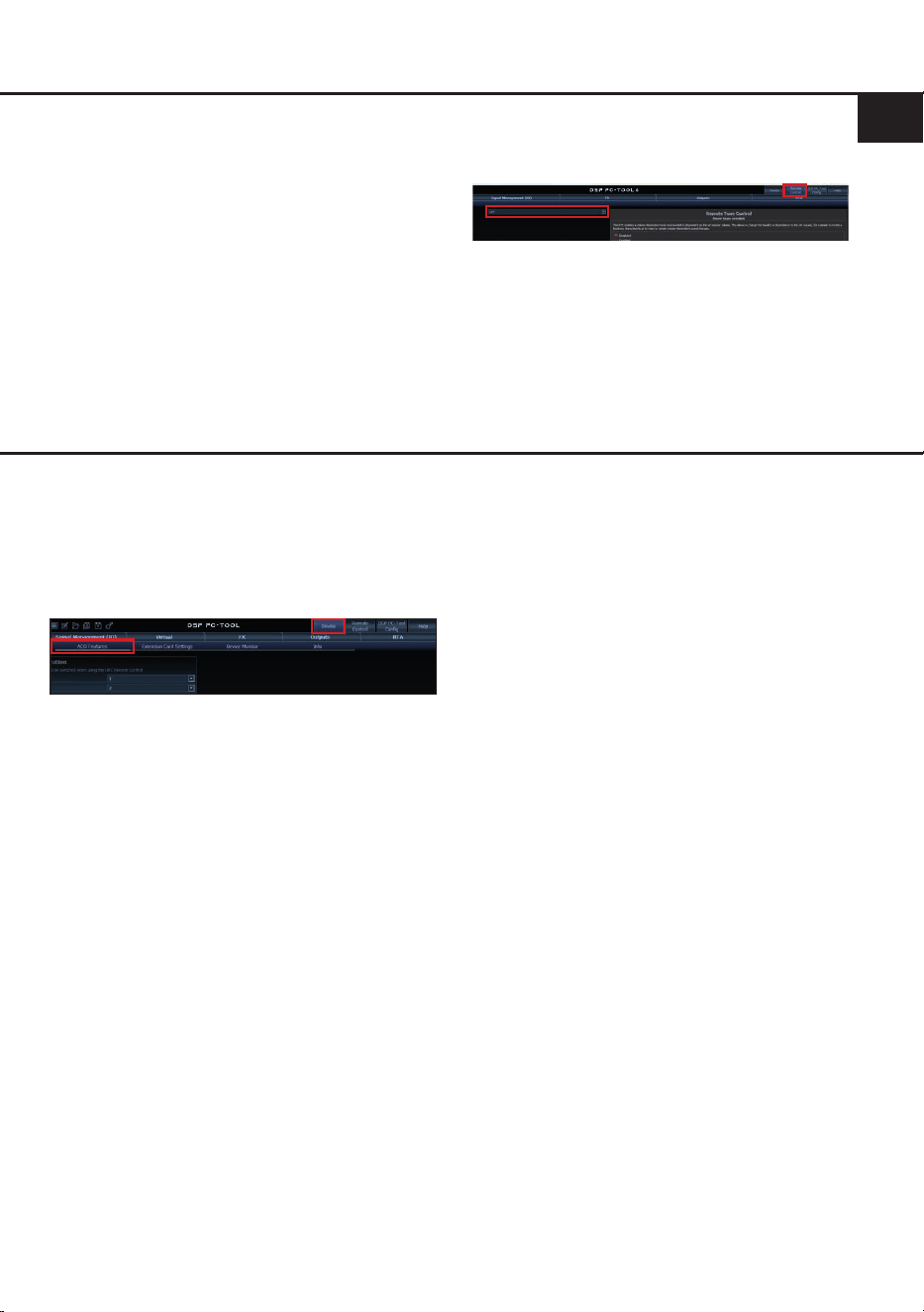
- Die Fernbedienung muss in der DSP PC-Tool
Software im Reiter „Remote Control“ aktiviert
werden.
Nach dem Anschluss erkennt das ISM 400.2DSP
die Fernbedienung automatisch. In der Remote-
Control-Konguration des DSP PC-Tools können
– abhängig vom verwendeten Fernbedienungs-
modell – weitere Einstellungen vorgenommen
werden.
Konguration einer Subwoofer-Fernbedienung
ACO Plattform-Features
Neben den einzigartigen DSP-Sound eekten bie-
tet die ACO-Plattform des ISM 400.2DSP zusätz-
lich eine Vielzahl an System-Features.
Im „Device“-Menü der DSP PC-Tool Software kön-
nen für einige dieser System-Features individuelle
Einstellungen vorgenommen werden.
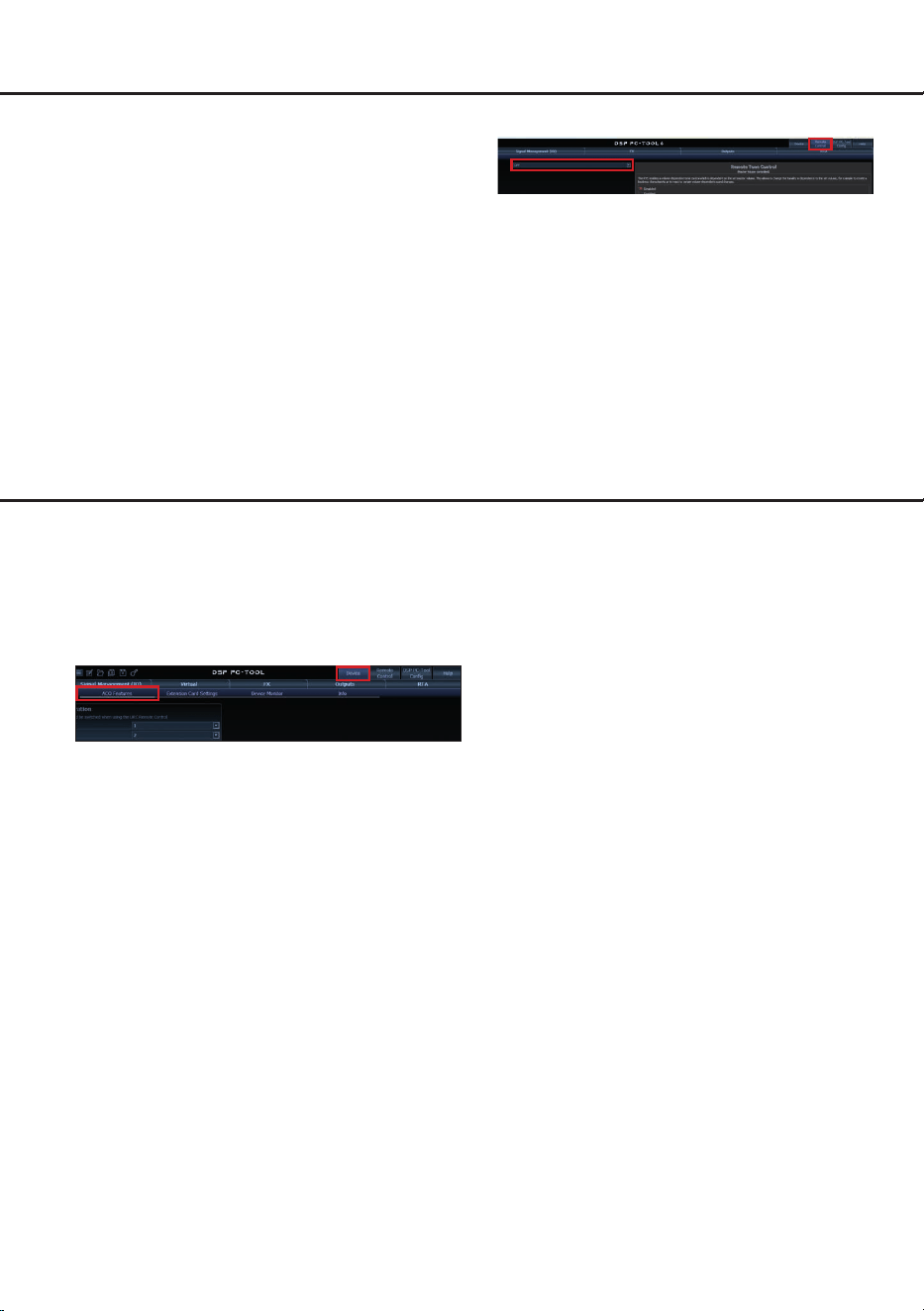
URC Setup Switch Conguration
Der ACO bietet Speicherplatz für zehn anstelle der
üblichen zwei Sound Setups.
Mit Hilfe einer optional erhältlichen URC Fernbe
-
dienung oder des Control Tasters (Seite 3, Punkt 1)
lässt sich zwischen zwei der zehn Sound-Setup
Speicherplätze umschalten. Diese zwei Speicher
-
plätze können in der „URC Setup Switch Con-
guration“ festgelegt werden. Werkseitig sind die
Speicherbereiche eins und zwei ausgewählt.
Um
zwischen allen internen Speicherplätzen umschal
-
ten zu können, werden die optional erhältlichen
Fernbedienungen DIRECTOR und CONDUCTOR
empfohlen.
Turn On & O Delay
Hier kann die Verzögerungzeit, mit welcher der in-
tegrierte DSP ein- und ausgeschaltet werden soll,
festgelegt werden. Werkseitig sind 0,2 Sekunden
eingestellt. Eine Änderung der Verzögerungszeit
sollte nur vorgenommen werden, wenn es bei-
spielsweise zu Störgeräuschen beim Ein- und
Ausschalten des Verstärkermoduls kommt.
Power Save Mode
Diese Funktion ist standardmäßig aktiviert und
dient der Reduzierung der Leistungsaufnahme
des Verstärkermoduls, wenn über einen bestimm-
ten Zeitraum kein Musiksignal erkannt wird.
Wird der Power Save Mode aktiv, schalten sich
die internen Verstärkerstufen automatisch ab.
Liegt anschließend wieder ein Musiksignal an,
kehrt das Gerät innerhalb von ca. 2 Sekunden in
den Normalbetrieb zurück.
Über die DSP PC-Tool Software kann die Funktion
ein- oder ausgeschaltet werden. Ist sie aktiviert,
lässt sich die Abschaltverzögerung im Bereich von
10 bis 600 Sekunden frei einstellen. Werkseitig
beträgt die Verzögerungszeit 60 Sekunden.

14
Leistung RMS (≤ 1% THD+N @ 50 Hz)
- @ 4 Ohm ................................................................ 2 x 130 Watt
- @ 2 Ohm ................................................................ 2 x 200 Watt
Max. Leistung (≤ 10% THD+N)................................. Bis zu 460 Watt RMS @ 2 x 2 Ohm
Verstärkertechnologie ............................................... Class HD
Eingänge .................................................................. 2 x Cinch
2 x Hochpegel-Lautsprechereingang
Eingangsempndlichkeit ........................................... Cinch: 0,4 - 8 Volt
Hochpegel: 1,6 - 32 Volt
Eingangsimpedanz ................................................... Cinch: 47 kOhm
Hochpegel: 9 - 33
Ohm mit ADEP.3
Ausgänge ................................................................. 2 x Lautsprecherausgang
1 x AISA-Signalausgang
Frequenzbereich....................................................... 10 Hz - 20.000 Hz
DSP Auösung ......................................................... 64 Bit
DSP Rechenleistung ................................................ 295 MHz (1,2 Mrd. MAC Operationen/Sek.)
Abtastrate ................................................................. 48 kHz
DSP Typ ................................................................... Audio Signalprozessor
Signalwandler ........................................................... A/D: BurrBrown 32 Bit
D/A: AKM 32 Bit
Signal- / Rauschabstand (A-bewertet)...................... 102 dB @ Maximalleistung
Klirrfaktor (THD @ 50 Hz, 1 W an 4 Ohm) ............... < 0,005 %
Klirrfaktor (THD+N @ 50 Hz, 1 W an 4 Ohm) .......... < 0,015 %
Dämpfungsfaktor ...................................................... 85
Betriebsspannung..................................................... 10,5 - 18 Volt (max. 5 Sek. bis hinab zu 6 Volt)
Leistungsaufnahme .................................................. DC 12 V
45 A max.
Leerlaufstromaufnahme............................................ 260 mA
Betriebstemperaturbereich ....................................... -40° C bis +70° C
Sicherung ................................................................. 1 x 40 A LP-Mini-Stecksicherung
Zusätzliche Features ................................................ Start-Stopfähigkeit, Clipping LED, DirectDSP-
Schalter, Smart Control Port, 32 Bit CoProcessor,
Masseschalter, Highlevel-Eingang mit automa-
tischer Einschaltung
Abmessungen (H x B x T) ........................................ 54 x 231 x 105 mm
Technische Daten
15
de
Die Garantieleistung entspricht der gesetzlichen Regelung. Von der Garantieleistung ausgeschlossen
sind Defekte und Schäden, die durch Überlastung oder unsachgemäße Behandlung entstanden sind.
Eine Rücksendung kann nur nach vorheriger Absprache in der Originalverpackung, einer detaillierten
Fehlerbeschreibung und einem gültigen Kaufbeleg erfolgen. Technische Änderungen, Druckfehler und
Irrtümer vorbehalten!
Für Schäden am Fahrzeug oder Gerätedefekte, hervorgerufen durch Bedienungsfehler des Gerätes,
können wir keine Haftung übernehmen.
Garantiehinweis
Dieses Produkt ist mit einer CE-Kennzeichnung versehen. Damit ist das Gerät für den Be-
trieb in Fahrzeugen innerhalb der Europäischen Union (EU) zertiziert.
Dieses Symbol bedeutet, dass das Produkt nicht über den Hausmüll entsorgt werden darf,
sondern bei einer entsprechenden Sammelstelle zum Recycling abgegeben werden muss.
Befolgen Sie die örtlichen Vorschriften und entsorgen Sie das Produkt niemals mit dem nor-
malen Hausmüll. Die ordnungsgemäße Entsorgung von Altgeräten trägt zur Vermeidung
von Umwelt- und Gesundheitsschäden bei.
Dieses Produkt ist mit einer UKCA-Kennzeichnung versehen. Damit ist das Gerät für den
Betrieb in Fahrzeugen innerhalb des Vereinigten Königreichs zertiziert.
Dieses Produkt ist mit einer EAC-Kennzeichnung versehen. Damit ist das Gerät für den
Betrieb in Fahrzeugen innerhalb der Eurasian Customs Union zertiziert.
Hinweise zur Entsorgung
Regulatorische Hinweise

16
General installation instructions for HELIX
components
To prevent damage to the unit and possible injury,
read this manual carefully and follow all installa-
tion instructions. This product has been checked
for proper function prior to shipping and is guaran-
teed against manufacturing defects.
For a proper performance and to ensure full war-
ranty coverage, we strongly recommend to get this
product installed by an authorized HELIX dealer.
• When mounting the module, make sure that
screws or tools do not damage any parts of the
enclosure or the subwoofer itself
• Ensure that the ISM sits ush on the mounting
surface and is securely fastened without vibra-
tion
• Make sure that all cables are routed to avoid
pinching, crushing, or excessive bending
• Do not expose the device to moisture or water
Important note:
Improper installation or incorrect wiring may re-
sult in damage to the amplier module or the
subwoofer. Professional installation is therefore
mandatory.
General instructions for connecting the HELIX
IMPACT ISM 400.2DSP amplier module
The ISM 400.2DSP may only be installed in vehi-
cles which have a 12 Volts negative terminal con-
nected to the chassis ground. Any other system
could cause damage to the amplier module and
the electrical system of the vehicle.
The positive cable from the battery for the com-
plete system should be provided with a main fuse
at a distance of max. 30 cm from the battery. The
value of the fuse is calculated from the maximum
total current input of the car audio system and the
cable cross section used.
Use only suitable cables with sucient ca-
ble cross-section when connecting the
ISM 400.2DSP. The fuse must only be replaced
with the same rating (40 A) to prevent damage
to the device. Using higher-rated fuses may re-
sult in serious secondary damage.
Prior to installation, plan the cable routing to
avoid any possible damage to the wiring harness.
All cabling should be protected against pinching
or crushing hazards. Also avoid routing cables
close to potential noise sources such as electric
motors, high-power accessories and other vehicle
harnesses.
Congratulations!
General instructions
Dear Customer,
Congratulations on your purchase of the HELIX
IMPACT ISM 400.2DSP, a high-quality subwoofer
amplier module with integrated DSP.
The ISM 400.2DSP is based on more than 35 years
of experience in the research and development of
audio components. It was developed using state-
of-the-art engineering, which is reected in its
excellent build quality and the use of sophisticated
technologies.
We wish you many hours of enjoyment with your
new HELIX IMPACT ISM 400.2DSP.
Yours,
AUDIOTEC FISCHER
17
1
Control pushbutton
Page 25, point 4
2
DirectDSP switch
Page 21, point 2
3
Voltage range switch
Page 21, point 1
4
Gain control
Page 23, point 8
5
SCP (Smart Control Port)
Page 25, point 2
6
USB input
Page 23, point 7
7
Status LED
Page 25, point 1
8
Clipping LED
Page 25, point 3
9
Signal inputs
Page 21 - 22, point 3 - 5
10
Power connector
Page 22, point 6
11
Fuse
Page 27
1
3
2 4
5 76 109 118
12 13
Rear side ISM 400.2DSP
12
Speaker outputs
Page 19 bottom
13
Input reference switch
Page 24, point 12
en
Connectors and control units

18
The HELIX IMPACT ISM 400.2DSP is a compact amplier module that converts a passive 2 × 2 Ohms
subwoofer into an active one. It can be used as an upgrade for the passive terminal of HELIX IMPACT
DVC2 enclosure subwoofers or as the basis for building a custom active subwoofer.
1. Upgrade for the passive terminal of a HELIX IMPACT DVC2 enclosure subwoofer
i. Loosen the mounting screws of the passive
terminal
ii. Carefully pull the terminal toward the front
v. Insert the ISM 400.2DSP into the cut-out vi. Secure the ISM 400.2DSP using the screws previously
removed from the passive terminal
iii. Disconnect the cable connection on the rear of the
passive terminal
iv. Connect the subwoofer chassis connection cable to
the ISM 400.2DSP module
from
subwoofer chassis
Rear view
from
subwoofer chassis
Rear view
Installation & setup
19
en
2. Universal installation for building an active subwoofer
i. Connect the ISM 400.2DSP speaker connection cable (page 20, g. 2) to the speaker chassis.
Minimum total impedance 2 x 2 Ohms.
iii. Insert the ISM 400.2DSP into the cut-out
iv. Secure the ISM 400.2DSP using the supplied
mounting screws
Molex speaker
connection cable -
front view
VC2 VC1
ii. Connect the speaker connection cable to the
ISM 400.2DSP module
from
subwoofer chassis
Rear view
Note on connecting the speaker outputs
Connect the speaker outputs (page 17, point 12) exclusively using the supplied connection cable with
the 4-pin connector and ying leads (page 20, g. 2). The supplied connection cable must be profes-
sionally extended to connect the loudspeakers. Use suitable speaker cables and ensure a permanently
secure electrical connection.
Ensure that the loudspeakers are correctly connected (in phase), i.e., plus to plus and minus to minus.
Exchanging plus and minus will result in a complete loss of bass response. The positive terminal is
marked on most speakers.
The impedance of each channel must not be less than 2 Ohms, otherwise the protection circuit of the
amplier module will be activated.
Molex speaker
connection cable -
front view
Speaker impedance
2 x 2 Ω 1 x 2 Ω 1 x 2 Ω
Speaker impedance
OR
20
Hardware conguration
Fig. 1: Pin conguration of the Signal Input
Signal Input
1. Highlevel speaker input left (+)
2. Highlevel speaker input right (+)
3. Lowlevel line input left (RCA)
4. Lowlevel line input right (RCA)
5. Remote input
6. Highlevel speaker input left (-)
7. Highlevel speaker input right (-)
8. Lowlevel ground (RCA)
9. AISA ground
10. AISA signal output
Fig. 2: Overview connection cables
1
2
Connection cable power connection (Power Input)
Connection cable Signal Input
Loudspeaker connection cable
1
2
109876
54321
3
3

21
en
After installing the amplier module and con-
necting it to the subwoofer(s), congure the
HELIX IMPACT ISM 400.2DSP as follows
Caution: Carrying out the following steps will
require special tools and technical knowledge. In
order to avoid connection mistakes and / or dam-
age, ask your dealer for assistance if you have any
questions and follow all instructions in this manual
(see page 16). It is recommended that this unit will
be installed by an authorized HELIX dealer.
1. Adjusting the input voltage range and in-
put impedance (ADEP.3) of the analog in-
puts
ATTENTION: This setting must be made
before initial operation to prevent damage to
the amplier module or the connected sound
system.
The analog input channels of the ampli-
er module can be driven by either lowlevel
(RCA / Cinch) or highlevel (speaker wires)
signals. To ensure optimal signal quality, the
input voltage range and impedance (ADEP.3)
of the signal input must be set using the volt-
age range switch (page 17, point 3) according
to the signal type used.
We recommend measuring the maximum out-
put voltage of the signal source using an ap-
propriate measuring device or contacting your
authorized HELIX dealer. If you are unsure,
we recommend setting the switch to the right
switch position (RCA 8 V / High 32 V) to avoid
potential damage to the device.
Left switch position (16 V / 4 V):
Select this setting for standard applications
such as connecting:
- Audiotec Fischer DSP ampliers via RCA
cables
- Factory head units
- Aftermarket head units with maximum 4 V
RMS output voltage
In this position, the input voltage range is 0.4 –
4 V for the lowlevel line input and 1.6 – 16 V
for the highlevel input.
Right switch position (32 V / 8 V):
Select this setting when connecting devices
from the following categories:
- Aftermarket head units with more than 4 V
RMS output voltage
- Premium sound system ampliers with
more than 50 W RMS output power
- Stand-alone DSPs with more than 4 V
RMS output voltage
In this position, the input voltage range is 0.8 –
8 V for the lowlevel line input and 3.2 – 32 V
for the highlevel input.
2. Setting the DirectDSP switch
The ISM 400.2DSP is equipped with a
DirectDSP switch that determines how the in-
put signal is processed.
By default, the switch is set to “O”, which ac-
tivates the internal DSP and allows the ampli-
er module to be congured using the DSP
PC-Tool.
O (factory default): The input signal is pro-
cessed by the internal DSP. For standard
applications, such as a direct connection to
a head unit or another signal source without
DSP, this setting must be selected. In this
case, all lter settings, including highpass,
subsonic, and lowpass lters, must be cong-
ured via the DSP PC-Tool.
On: The internal DSP is disabled. The input
signal is directly passed to the speaker out-
puts unprocessed.
Important: This setting should only be se-
lected if all required crossover frequencies for
highpass, subsonic, and lowpass are already
congured in a preceding DSP or DSP ampli-
er.
3. Connecting the line inputs
The two lowlevel line inputs of the signal input
can be connected to the RCA / Cinch outputs
of the signal source (e.g. head unit, DSP, or
DSP amplier) using the supplied connection
cable (page 20, g. 2) and appropriate cables.
It is not mandatory to connect both inputs. If
only one channel is connected, we recom-
mend using the left input channel.
The input sensitivity can be optimally adjusted
to the signal source using the Gain control and
Clipping LED (page 17, point 4 & 8).

22
Hardware conguration
The automatic turn-on function (Auto Remote)
does not work when using the line inputs. In
this case the Remote IN of the signal input has
to be connected.
Important: The highlevel speaker inputs and
the lowlevel line inputs must not be used si-
multaneously, as this may damage the sound
system.
4. Connecting the highlevel speaker inputs
The two highlevel speaker inputs of the Signal
Input can be connected directly to the speaker
outputs of the signal source (e.g. head unit or
DSP amplier) using the supplied connection
cable (page 20, g. 2).
Recommended channel assignment:
Stereo signal source:
When using a stereo signal source, both
highlevel speaker inputs (left and right) of the
ISM 400.2DSP must be connected.
Mono signal source:
When using a mono signal source, connect
the signal exclusively to the left highlevel
speaker input.
Make sure that the polarity is correct. If one
connection has reversed polarity it may aect
the performance of the amplier module.
The input sensitivity can be optimally adjusted
to the signal source using the Gain control and
Clipping LED (page 17, point 4 & 8).
The amplier module is equipped with our pro-
prietary ADEP.3 circuit (Advanced Diagnos-
tics Error Protection, 3rd generation) which
ensures that the OEM head unit detects the
amplier module as a speaker. As a result, no
functions are disabled, and no error logs are
stored in the vehicle’s diagnostic memory.
The left highlevel speaker input is additionally
equipped with an automatic turn-on function
activated by a music signal. When this input
is used, the amplier module automatically
switches on with all common head units and
amplier signals. In this case, the remote input
of the signal input (Remote IN) does not need
to be connected.
Attention: Use only the supplied connection
cable for the connection (page 20, g. 2)!
Important: The highlevel speaker inputs and
the lowlevel line inputs must not be used
simultaneously, as this may damage the
sound system.
5. Connecting the remote input
The remote input is used to switch the
ISM 400.2DSP on and o when the lowlevel
line inputs of the Signal Input are used. Con-
nect the remote input of the amplier module
to the remote output of the preceding device
(aftermarket head unit, DSP, or DSP amplier)
that provides the input signal.
We do not recommend controlling the remote
input via the ignition switch to avoid pop noise
during turn on / o.
Note: This input does not need to be connect-
ed if the left highlevel speaker input is used.
Note: Connect the Remote IN input only us-
ing the supplied signal input connection cable
(page 20, g. 2).
6. Connecting the power supply
ATTENTION: Make sure to disconnect the
battery before installing the ISM 400.2DSP!
Connect the power supply only using the sup-
plied Power Input cable (page 20, g. 2).
Make sure of correct polarity.
+12 V (yellow wire): Connect the +12 V pow-
er cable to the positive terminal of the bat-
tery. The positive wire from the battery to the
ampliers power terminal needs to have an
inline fuse at a distance of no more than 12
inches (30 cm) from the battery. The value of
the fuse is calculated from the maximum total
current input of the whole car audio system
(ISM 400.2DSP = max. 45 A at 12 V power
supply). If your power wires are short (less
than 1 m / 40”) then a wire gauge of 6 mm² /
AWG 10 will be sucient. In all other cases we
strongly recommend gauges of 10 - 16 mm² /
AWG 8 – 6!
GND (black wire): The ground wire should
be connected to a common ground reference
point (this is located where the negative ter-
minal of the battery is grounded to the metal
body of the vehicle) or to a prepared metal
location on the vehicle chassis, i.e., an area
cleaned of all paint residues. The cable should
have the same gauge as the +12 V wire. Inad-
equate grounding causes audible interference
and malfunctions.
23
en
7. Connecting the PC & rst start-up
The USB-C input (page 17, point 6) enables
the connection of the amplier to a personal
computer and its free conguration with our
DSP PC-Tool software using the provided
USB cable.
Before you connect the ISM 400.2DSP to
a computer for the rst time, download the
latest DSP PC-Tool software (at least ver-
sion 6) from our homepage. The software
and a comprehensive knowledge base can be
found at www.audiotec-scher.com.
It is advisable to check regularly for software
updates so that the device is always up to
date. We strongly recommend to carefully
read the DSP PC-Tool knowledge base before
using the software for the rst time in order to
avoid any complications and failures.
Important: Make sure that the amplier mod-
ule is not connected to your computer before
the software and USB driver are installed!
In the following the most important steps how
to connect and the rst start-up are described:
1. Download the latest version of the DSP
PC-Tool software (available on our web-
site www.audiotec-scher.com) and in-
stall it on your computer.
2. Connect the amplier module to your com-
puter using the USB cable that is included
in delivery. If you have to bridge longer dis-
tances please use an active USB exten-
sion cable with integrated repeater.
3. First turn on the ISM 400.2DSP and then
start the software. The operating software
will be updated automatically to the latest
version if it is not up-to-date.
8. Adjustment of the input sensitivity of the
analog signal inputs
ATTENTION: It is mandatory to properly adapt
the input sensitivity of the ISM 400.2DSP to
the signal source to achieve the best possible
signal quality and avoid damage to the am-
plier module. It is also mandatory to adjust
the input voltage range and the input imped-
ance (ADEP.3) of the signal inputs to the out-
put voltage of your signal source (page 21,
point 1).
The input sensitivity can be optimally adapt-
ed to the signal source using the gain control
(page 17, point 4). This control aects both
highlevel and lowlevel line inputs.
Note that the gain control is not a volume con-
trol. It is used to adjust the amplier’s gain.
Adjustment ranges
Left switch position:
Highlevel: 1.6 - 16 Volts
RCA / Cinch: 0.4 - 4 Volts
Right switch position:
Highlevel: 3.2 - 32 Volts
RCA / Cinch: 0.8 - 8 Volts
Input sensitivity is factory set to max. 16 Volts
highlevel / 4 Volts RCA. In most cases, this is
the optimal setting.
If the signal source provides a lower output
voltage, the input sensitivity can be increased.
Conversely, if the signal source provides a
higher output voltage, such as when a fac-
tory installed amplier is used as the signal
source, the input sensitivity must be reduced,
and the correct position of the voltage range
switch must be checked (page 21, point 1).
If you are unsure about the output voltage of
your signal source, please contact your autho-
rized HELIX dealer.
The Clipping LED (page 17, point 8) serves as
monitoring tool.
Attention: It is strongly recommended to
mute the signal outputs of the ISM 400.2DSP
in the DSP PC-Tool before adjusting the input
sensitivity, as otherwise there is a risk of dam-
age to the speakers.
Procedure for setting the input sensitivity:
1. Ensure that the input voltage range and
the input impedance (ADEP.3) of the an-
24
Hardware conguration
alog signal inputs are correctly adjusted to
the signal source (page 21, point 1). This
setting must be done before adjusting the
input sensitivity.
2. Connect the amplier module to a com-
puter and start the DSP PC-Tool software
(page 23, point 7). Then mute the speaker
outputs of the module in the software.
3. Adjust the volume of your radio to approx.
90 % of the maximum volume and play
back a suitable test signal – ideally our spe-
cially developed “IGS – Input Gain Setup”
signal, which can be found under “Audio
Test Tracks” in the DSP PC-Tool or down-
loaded from www.audiotec-scher.com.
4. Normally, the Clipping LED is o and only
lights up if one of the analog inputs is over-
driven.
Now increase the input sensitivity by turn-
ing the Gain control clockwise and, if nec-
essary, by setting the Voltage Range switch
to the left 16 V position until the Clipping
LED lights up.
5. Now turn the control counterclockwise until
the Clipping LED turns o again.
9. Conguration of the internal DSP
IMPORTANT: Conguration of the internal
DSP is required only when the DirectDSP
switch is set to “O” and no preceding DSP
or DSP amplier is used. In this case, the in-
ternal DSP of the ISM 400.2DSP performs all
signal processing.
Before initial operation, we strongly recom-
mend conguring the basic settings in the
DSP PC-Tool to prevent damage to connected
speakers.
After connecting the device to a PC, the am-
plier module can be congured in the DSP
PC-Tool. Useful hints for the correct set-
ting can be found in our knowledge base at
www.audiotec-scher.com.
Caution: At the start of conguration, set the
head unit volume to minimum and mute the
outputs in the software to prevent speaker
damage.
10. Optional: Analyzing the input signal
When using the highlevel inputs, we recom-
mend analyzing the input signal with the Ad-
vanced Input Signal Analyzer (AISA) in the
DSP PC-Tool. This helps detect and correct
factory-set equalization, time alignment, or all-
pass lters if present.
The ISM 400.2DSP provides an AISA signal
output (page 20, g. 1) on the 10-pin connec-
tor of the Signal Input. The input signal can be
routed from this output to suitable measure-
ment equipment, such as the Audiotec Fischer
AMI, for analysis.
Information on the AISA can be found in the
extensive Knowledge Base on our website
www.audiotec-scher.com.
11. Sound tuning
Now you can create your sound setup.
Information about sound tuning can be
found in our extensive knowledge base at
www.audiotec-scher.com or contact your
local HELIX dealer.
12. Optional: Conguration of the input refer-
ence
In some cases, noise may occur and it may be
necessary to adjust the signal ground of the
signal inputs. Use the ground switch on the
rear of the module.
Float: In this switch position, the signal ground
is separated from the vehicle’s ground by a
dierential amplier. This is usually the best
setting in most vehicles to prevent interfer-
ence noise, e.g. from the alternator.
GND: The signal ground is tied together with
the vehicle’s ground. This setting should be
selected if noise occurs in the “Float” position.
25
en
1. Status LED
The Status LED indicates the operating mode
of the amplier module and of its memory.
Green: Amplier module is ready for operation.
Orange: Power Save Mode is active.
Red: Protection Mode is active. This may have
dierent root causes. The ISM 400.2DSP
is equipped with protection circuits against
over- and undervoltage as well as overheat-
ing. Please check for connecting failures such
as short-circuits or other wrong connections.
If the amplier module is overheated the inter-
nal temperature protection switches o the re-
mote and signal output until it reaches a safe
temperature level again.
Red / green slow ashing: No operating soft-
ware installed. Connect the amplier module
to the DSP PC-Tool software and conrm the
automatic update of the operating system.
You will nd the latest version of the DSP PC-
Tool software at www.audiotec-scher.com.
Red / green fast ashing: The currently se-
lected sound setup memory is empty. A new
setup has to be loaded via the DSP PC-Tool
software or switch to a memory position with
existing sound setup.
2. SCP (Smart Control Port)
This multi-functional input (page 17, point 5)
is used to connect HELIX accessory products,
such as a remote control, which allows the
user to adjust several features of the ampli-
er module. Depending on the type of remote
control, at rst its functionality has to be de-
ned in the “ Remote Control” menu of the
DSP PC-Tool software.
Attention: If the accessory product does not
have a NanoFit connector, a SCP-to-Control
Input adaptor (Art-Nr. M141313) is optionally
available from your specialist dealer.
3. Clipping LED
Normally, the Clipping LED is o and only lights
up if one of the analog inputs is overdriven.
On (red): One of the analog signal inputs is
overdriven. Reduce the input sensitivity using
the Gain control until the LED goes out. In
-
structions on how to reduce the input sensitivity
are described on page 23, point 8.
4. Control pushbutton
The ISM 400.2DSP provides 10 internal mem-
ory locations for sound setups. The Control
pushbutton allows the user to switch between
two memory positions. These can be dened
in the DSP PC-Tool. In addition a device reset
can be made by pressing the button for a lon-
ger period.
1. Setup switch: Press Control pushbutton for
1 second. The memory locations one and two
are dened by default. Switching is indicated
by a single red ash of the Status LED. Al-
ternatively, the optional URC.3 remote control
can be used for switching. To switch between
all internal memory locations, optional acces-
sories like the DIRECTOR display remote
control or CONDUCTOR are required.
2. Device reset: Press pushbutton for ve
seconds. This completely erases the internal
memory and is indicated by a continuous red
glowing and constant green ashing of the
Status LED.
Attention: After erasing the setups from
memory the ISM 400.2DSP will not reproduce
any audio output until the device is updated
via the DSP PC-Tool software.
SCP-to-Control Input adaptor
Additional functions
26
An optional remote control, such as the HELIX
URC.1 or URC.3, can be connected to the
ISM 400.2DSP via the SCP (Smart Control Port /
page 17, point 5). This allows functions such as
subwoofer level control or switching between
sound setups to be conveniently adjusted from
the driver’s seat.
To use a remote control, the following require-
ments must be met:
- The DirectDSP switch (page 17, point 2) must
be set to “O” so that the internal DSP is active.
- The remote control must be enabled in the DSP
PC-Tool software under the Remote Control tab.
After connection, the ISM 400.2DSP automatically
detects the remote control. Depending on the re-
mote control model used, additional settings can
be congured in the Remote Control section of the
DSP PC-Tool.
Conguration of a subwoofer remote control
ACO platform features
Beside the unique DSP sound eects the
ISM 400.2DSP provides a bunch of system and
DSP features.
In the “Device” menu of the DSP PC-Tool soft-
ware individual settings can be made for several
of these system features.
URC Setup Switch Conguration
The ACO provides ten internal memory locations
for sound setups instead of the common two.
By using an optional URC remote control or the
Control pushbutton (page 17, point 1) it is pos
-
sible to toggle between two of the ten memory
locations. These two memory locations can be
determined in the “URC Setup Switch Congu
-
ration”. The memory locations one and two are
preassigned by default. To switch between all in
-
ternal memory locations, the optionally available
remote controls DIRECTOR and CONDUCTOR
are recommended.
Turn On & O Delay
This function allows to determine the delay time
with which the integrated DSP is switched on and
o. The factory setting is 0.2 seconds. The delay
time should only be modied if there are e.g. nois-
es while switching on / o the amplier module.
Power Save Mode
This function is activated by default and is used
to reduce the power consumption of the amplier
module if no music signal is detected for a certain
period of time.
When power save mode is active, the internal am-
plier stages are automatically switched o. Once
a music signal is detected again, the device re-
turns to normal operation within approximately 2
seconds.
The function can be switched on or o using
the DSP PC-Tool software. If it is activated, the
switch-o delay can be freely set in the range from
10 to 600 seconds. The default delay time is 60
seconds.

27
en
Technical data
Power RMS (≤ 1% THD+N @ 50 Hz)
- @ 4 Ohms .............................................................2 x 130 Watts
- @ 2 Ohms .............................................................2 x 200 Watts
Max. output power (≤ 10% THD+N) ........................ Up to 460 Watts RMS @ 2 x 2 Ohms
Amplier technology ................................................Class HD
Inputs ....................................................................... 2 x RCA / Cinch
2 x Highlevel speaker input
Input sensitivity ........................................................ RCA / Cinch: 0.4 - 8 Volts
Highlevel: 1.6 - 16 Volts
Input impedance ...................................................... RCA / Cinch: 47 kOhms
Highlevel: 9 - 33
Ohms with ADEP.3
Outputs .................................................................... 2 x Speaker output
1 x AISA signal output
Frequency range .....................................................10 Hz - 20,000 Hz
DSP resolution .........................................................64 Bit
DSP power ..............................................................295 MHz (1.2 billion MAC operations/sec.)
Sampling rate ..........................................................48 kHz
DSP type .................................................................Audio signal processor
Signal converters ..................................................... A/D: BurrBrown 32 Bit
D/A: AKM 32 Bit
Signal-to-noise ratio (A-weighted) ........................... 102 dB @ full power
Distortion (THD @ 50 Hz, 1 W into 4 Ohms) ...........< 0.005 %
Distortion (THD+N @ 50 Hz, 1 W into 4 Ohms) ...... < 0.015 %
Damping factor ........................................................85
Operating voltage ....................................................10.5 - 18 Volts (max. 5 sec. down to 6 Volts)
Power rating ............................................................DC 12 V
45 A max.
Idle current...............................................................260 mA
Operating temperature range ..................................-40° C to +70° C
Fuse.........................................................................1 x 40 A LP-Mini-fuse (APS)
Additional features ................................................... Start-Stop capability, Clipping LED, DirectDSP
switch, Smart Control Port, 32 Bit CoProcessor,
ground lift switch, highlevel input with automatic
turn-on function
Dimensions (H x W x D) ..........................................54 x 231 x 105 mm / 2.13 x 9.09 x 4.13”
Audiotec Fischer GmbH
Hünegräben 26 - 28 · 57392 Schmallenberg · Germany
Tel.: +49 2972 9788 0 · Fax: +49 2972 9788 88
E-mail: helix@audiotec-scher.com · Internet: www.audiotec-scher.com
Made in Germany
The warranty service is based on the statutory regulations. Defects and damage caused by overload
or improper handling are excluded from the warranty service. Any return can only take place following
prior consultation, in the original packaging together with a detailed description of the error and a valid
proof of purchase.
Technical modications, misprints and errors excepted! For damages on the vehicle and the device,
caused by handling errors of the device, we can’t assume liability.
Warranty disclaimer
This product has been issued a CE marking. This means that the device is certied for use
in vehicles within the European Union (EU).
This symbol means the product must not be discarded as household waste, and should
be delivered to an appropriate collection facility for recycling. Follow local rules and never
dispose of the product with normal household waste. Correct disposal of old products helps
prevent negative consequences for the environment and human health.
This product has been issued an UKCA marking. This means that the device is certied for
use in vehicles within the United Kingdom.
This product has been issued an EAC marking. This means that the device is certied for
use in vehicles within the Eurasian Customs Union.
Correct disposal of this product
Regular notes