de
en
User Manual
Bedienungsanleitung
16-channel high-end digital signal processor
Digitaler 16-Kanal High-End Signalprozessor
DSP ULTRA XT

2
Sehr geehrter Kunde,
wir gratulieren Ihnen zum Kauf dieses hochwertigen
HELIX-Signalprozessors.
Audiotec Fischer setzt mit dem HELIX NEXT
DSP ULTRA XT neue Maßstäbe im Bereich der
Signalprozessortechnik. Dabei protieren Sie als
Kunde direkt von unserer mehr als 35-jährigen
Erfahrung in der Forschung und Entwicklung von
Audiokomponenten.
Dieser Signalprozessor wurde von uns nach
neuesten technischen Erkenntnissen entwickelt
und zeichnet sich durch hervorragende
Verarbeitung und eine überzeugende Anwendung
ausgereifter Technologien aus.
Viel Freude an diesem Produkt wünscht Ihnen das
Team von
AUDIOTEC FISCHER
Allgemeines zum Einbau von HELIX-Kompo-
nenten
Um alle Möglichkeiten des Produktes optimal aus-
schöpfen zu können, lesen Sie bitte sorgfältig die
nachfolgenden Installationshinweise. Wir garan
-
tieren, dass jedes Gerät vor Versand auf seinen
einwandfreien Zustand überprüft wurde.
Vor Beginn der Installation unterbrechen Sie
den Minusanschluss der Autobatterie.
Wir empfehlen Ihnen, die Installation von einem
Einbauspezialisten vornehmen zu lassen, da der
Nachweis eines fachgerechten Einbaus und An
-
schlusses des Gerätes Voraussetzung für die Ga-
rantieleistungen ist.
Installieren Sie Ihren Signalprozessor an einer
trockenen Stelle im Fahrzeug und vergewissern
Sie sich, dass der Signalprozessor am Montage
-
ort genügend Kühlung erhält. Montieren Sie das
Gerät nicht in zu kleine, abgeschlossene Gehäuse
ohne Luftzirkulation oder in der Nähe von wärme
-
abstrahlenden Teilen oder elektronischen Steu-
erungen des Fahrzeuges. Im Sinne der Unfallsi-
cherheit muss der Signalprozessor professionell
befestigt werden. Dies geschieht über Schrauben,
die in eine Montageäche eingeschraubt werden,
die wiederum genügend Halt bieten muss.
Bevor Sie die Schrauben im Montagefeld befes
-
tigen, vergewissern Sie sich, dass keine elekt-
rischen Kabel und Komponenten, hydraulische
Bremsleitungen, der Benzintank etc. dahinter ver
-
borgen sind. Diese könnten sonst beschädigt wer-
den. Achten Sie bitte darauf, dass sich solche Teile
auch in der doppelten Wandverkleidung verbergen
können.
Allgemeines zum Anschluss des HELIX NEXT
DSP ULTRA XT Signalprozessors
Der Signalprozessor darf nur in Kraftfahrzeu
-
ge eingebaut werden, die den 12 V-Minuspol an
Masse haben. Bei anderen Systemen können der
HELIX Signalprozessor und die elektrische Anlage
des Kfz beschädigt werden. Die Plusleitung für die
gesamte Anlage sollte in einem Abstand von max.
30 cm von der Batterie mit einer Hauptsicherung
abgesichert werden. Der Wert der Sicherung er
-
rechnet sich aus der maximalen Stromaufnahme
der Car-Hi Anlage und dem verwendeten Lei
-
tungsquerschnitt.
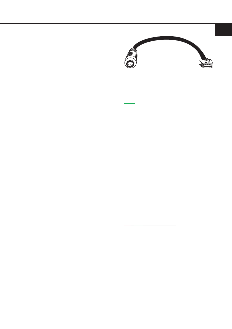
Verwenden Sie zum Anschluss des Signalpro-
zessors an die Stromversorgung des Fahr-
zeugs ausschließlich den beiliegenden An-
schlussstecker.
Die Kabelverbindungen müssen so verlegt sein,
dass keine Klemm-, Quetsch- oder Bruchgefahr
besteht. Bei scharfen Kanten, z. B. Blechdurchfüh
-
rungen, müssen alle Kabel gegen Durchscheuern
geschützt sein. Ferner darf das Versorgungskabel
niemals gemeinsam mit Zuleitungen zu Vorrichtun
-
gen des Kfz wie Lüftermotoren, Brandkontrollmo-
dulen, Benzinleitungen etc. verlegt werden.
Herzlichen Glückwunsch!
Allgemeine Hinweise
3
de
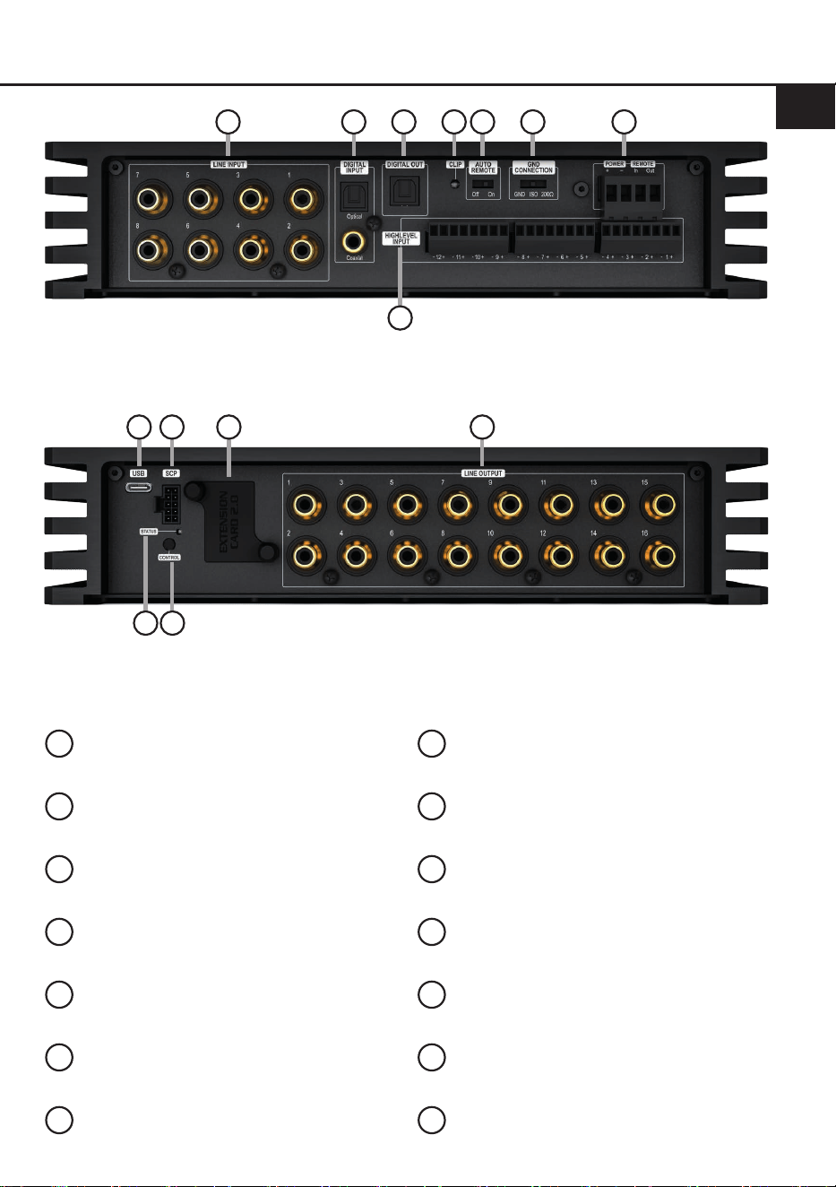
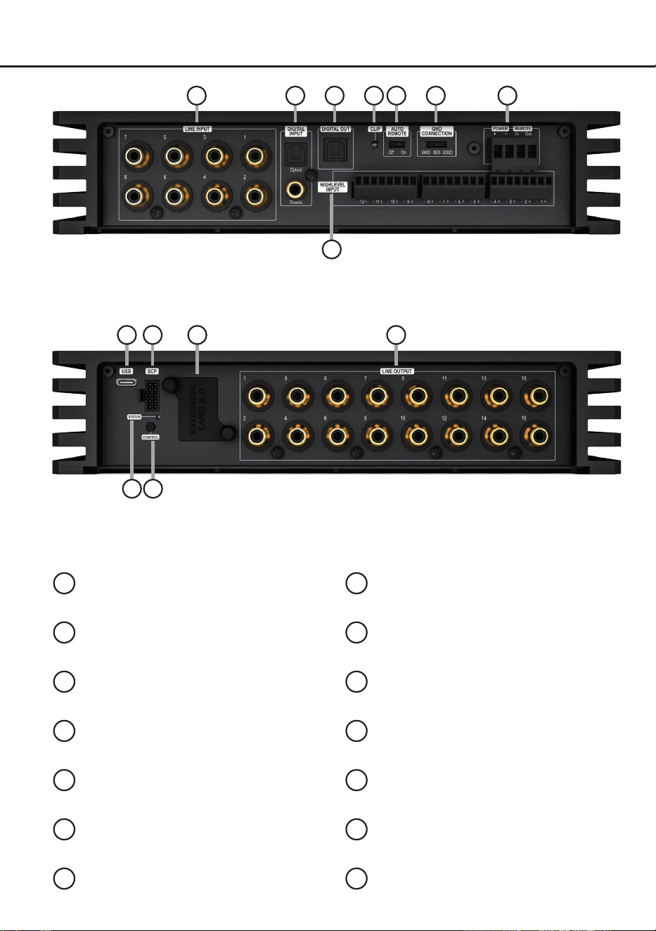
Anschluss- und Bedienelemente
1
Lowlevel-Vorverstärkereingänge
Seite 5, Punkt 2
2
Digitaleingänge (Coaxial & Optical)
Seite 5, Punkt 4
3
Optischer Digitalausgang
Seite 9, Punkt 14
4
Clipping LED
Seite 12, Punkt 5
5
Auto Remote-Schalter
Seite 6, Punkt 5
6
Masseschalter
Seite 12, Punkt 6
7
Anschluss Stromversorgung & Remote
Seite 6, Punkt 6
8
Highlevel-Lautsprechereingänge
Seite 5, Punkt 3
9
USB-C Eingang
Seite 7, Punkt 7 & Seite 11, Punkt 1
10
SCP (Smart Control Port)
Seite 11, Punkt 2
11
Extension Card 2.0 Slot
Seite 16
12
Vorverstärkerausgänge
Seite 9, Punkt 11
13
Status LED
Seite 11, Punkt 3
14
Control-Taster
Seite 11, Punkt 4
9 1110 12
13 14
1 32 4
8
5 6 7
4
Hardware-Konguration
Kongurieren Sie den HELIX NEXT
DSP ULTRA XT in der nachfolgenden
Reihenfolge
Achtung: Für die Durchführung der nachfol-
genden Schritte werden Spezialwerkzeuge und
Fachwissen benötigt. Um Anschlussfehler und
Beschädigungen zu vermeiden, fragen Sie im
Zweifelsfall Ihren Einbauspezialisten und beach-
ten Sie zwingend die allgemeinen Anschluss- und
Einbauhinweise (siehe Seite 2).
1. Einstellung des Eingangsspannungsbe-
reichs der analogen Signaleingänge
Bevor Sie beginnen, den Eingangsspan-
nungsbereich („Voltage Range“) der analogen
Signal eingänge anzupassen, beachten Sie
bitte die folgenden Hinweise.
Diese Einstellung ist nur erforderlich, wenn
Sie Geräte aus den folgenden Kategorien an-
schließen:
- Aftermarket-Radios mit mehr als 4 V RMS
Line (Cinch) Ausgangsspannung
- Werks-Soundsystem-Verstärker mit mehr
als 16 Volt Ausgangsspannung (siehe
Kongurationsbeispiele auf Seite 10)
Für Standardanwendungen wie den An-
schluss von:
- Original-Radios
- Aftermarket-Radios mit maximal 4 V RMS
Line (Cinch) Ausgangsspannung
ist diese Einstellung nicht erforderlich. In die-
sem Fall können Sie direkt auf Seite 5 mit
Punkt 2 fortfahren.
So stellen Sie den Eingangsspannungsbe-
reich ein:
a. Signalprozessor önen
Lösen Sie die zwölf Inbusschrauben des
Bodenblechs und nehmen Sie dieses ab.
b. Ausgangsspannung der Signalquelle
ermitteln
Wir empfehlen, die maximale Ausgangs-
spannung mithilfe eines geeigneten Mess-
geräts, z. B. mit dem Audiotec Fischer AMI,
zu ermitteln oder sich an Ihren autorisierten
HELIX Fachhändler zu wenden. Wenn Sie
unsicher sind, empfehlen wir, alle 6 Jumper
(J1 bis J6) auf den „High Voltage Range“
einzustellen (Line 2 - 8 V / Highlevel 8 -
32 V), um mögliche Schäden am Gerät zu
vermeiden. Stecken Sie dazu alle Jumper
(J1 - J6) auf die werkseitig unbenutzten
Stiftleisten, wie in Abbildung 2 gezeigt.
c. Jumper auf den entsprechenden Span-
nungsbereich setzen
Um die Position eines Jumpers zu ändern,
ziehen Sie ihn einfach nach oben ab und
stecken ihn in die gewünschte Position.
Achten Sie darauf, dass der Jumper voll-
ständig und ohne Versatz eingesteckt ist.
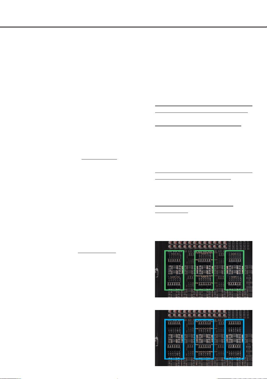
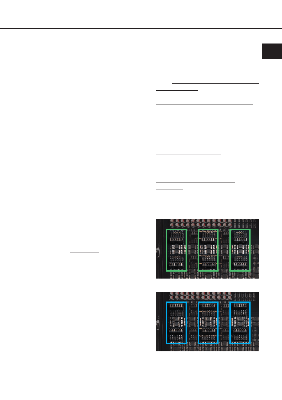
Übersicht Jumper-Steckpositionen:
Der DSP ULTRA XT verfügt über sechs
12-polige Jumper (J1 bis J6) zur Einstellung
der Voltage Range. Jeder Jumper stellt den
Wertebereich für jeweils ein analoges Ein
-
gangskanalpaar ein.
Low Voltage Range Konguration
(Werkseinstellung / siehe Abb. 1):
Wertebereich: Highlevel 4 - 16 Volt
Line (Cinch) 1 - 4 Volt
High Voltage Range Konguration
(siehe Abb. 2):
Wertebereich: Highlevel 8 - 32 Volt
Line (Cinch) 2 - 8 Volt
Abbildung 1:
J 1
J 2
J 3
J 4
J 5
J 6
Abbildung 2:
J 1
J 2
J 3
J 4
J 5
J 6

5
de
d.
Signalprozessor wieder zusammenbauen
Bauen Sie den Signalprozessor nach Ab-
schluss der Einstellung wieder vollständig
zusammen.
2. Anschluss der Vorverstärkereingänge
Die acht Vorverstärkereingänge (Line Input)
können mit entsprechenden Kabeln an die
RCA / Cinch-Ausgänge der Signalquelle, z. B.
Werksradio, Nachrüstradio oder Werksver-
stärker, angeschlossen werden. Mit Hilfe der
DSP PC-Tool Software können die Eingangs-
signale individuell auf die Ausgangskanäle
des Signalprozessors aufgeteilt werden. Die
Eingangsempndlichkeit ist für alle Kanäle ab
Werk auf 2,8 Volt eingestellt. Der verfügbare
Einstellbereich ist abhängig von der zuvor ge-
wählten „Voltage Range“ (siehe Punkt 1 „Ein-
stellung des Eingangsspannungsbereichs“)
und beträgt insgesamt 1 bis 8 Volt. Die Anpas-
sung erfolgt mit Hilfe der DSP PC-Tool Soft-
ware (siehe Seite 7, Punkt 8).
Die Einschaltautomatik des Signalprozessors
funktioniert bei den Vorverstärkereingängen
nicht, so dass der Remote-Eingang zwingend
belegt werden muss.
Achtung: Der Highlevel- und der Vorverstär-
kersignaleingang eines einzelnen Kanals darf
nicht gleichzeitig genutzt werden, da dies zu
Schäden an der Signalquelle führen kann. Es
ist jedoch zulässig, an einem Kanal den High-
level- und an einem anderen Kanal den Vor-
verstärkersignaleingang zu verwenden.
3. Anschluss der Highlevel-Lautsprecherein-
gänge
Die 12 Highlevel-Lautsprechereingänge
(Highlevel Input) können direkt mit den Laut-
sprecherausgängen des Werks- bzw. Nach-
rüstradios oder Werksverstärkers mit Hilfe
entsprechender Kabel (Lautsprecherkabel mit
max. 1 mm² Querschnitt) verbunden werden.
Sollten Sie ein normales Werksradio anschlie-
ßen, empfehlen wir folgende Kanalbelegung:
Kanal A = Vorne links
Kanal B = Vorne rechts
Kanal C = Hinten links
Kanal D = Hinten rechts
Dabei müssen nicht zwingend alle Eingän-
ge belegt werden. Werden nur zwei Kanäle
belegt, empfehlen wir die Kanäle A und B zu
verwenden. Achten Sie bitte auf eine korrekte
Polung. Wenn Sie einen oder mehrere An-
schlüsse verpolen, kann dadurch die Funktion
des Signalprozessors beeinträchtigt werden.
Bei Verwendung dieses Eingangs muss der
Remote-Eingang (REM) nicht belegt werden,
da sich der Signalprozessor automatisch ein-
schaltet, sobald ein Lautsprechersignal an-
liegt.
Die Eingangsempndlichkeit ist für alle Kanä-
le ab Werk auf 11,3 Volt voreingestellt.
Der verfügbare Einstellbereich ist abhängig
von der zuvor gewählten „Voltage Range“
( siehe Punkt 1 „Einstellung des Eingangs-
spannungsbereichs“) und beträgt insgesamt
4 bis 32 Volt. Die Anpassung erfolgt mit Hil-
fe der DSP PC-Tool Software (siehe Seite 7,
Punkt 8).
Achtung: Verwenden Sie zum Anschluss der
Highlevel-Lautsprechereingänge (Highlevel
Input) ausschließlich die mitgelieferten An-
schlussstecker.
Achtung: Der Highlevel- und der Vorverstär-
kersignaleingang eines einzelnen Kanals darf
nicht gleichzeitig genutzt werden, da dies zu
Schäden an der Signalquelle führen kann. Es
ist jedoch zulässig, an einem Kanal den High-
level- und an einem anderen Kanal den Vor-
verstärkersignaleingang zu verwenden.
4. Anschluss einer digitalen Signalquelle im
SPDIF-Format
Sofern Sie über eine Signalquelle mit koa-
xialem oder optischem Digitalausgang ver-
fügen, kann diese an den Signalprozessor
angeschlossen werden. Die Abtastrate (Sam-
pling Rate) muss zwischen 24 und 96 kHz für
den optischen Eingang und zwischen 24 und
192 kHz für den Koaxialeingang liegen. Das
Eingangssignal wird automatisch an die inter-
ne Abtastrate angepasst.
Werkseitig ist die manuelle Einschaltung des
optischen Eingangs über eine optionale Fern-
bedienung konguriert. Alternativ kann die
Einschaltung der Digitaleingänge in der DSP
PC-Tool Software unter dem Tab „Signal Ma-
nagement (IO)“ im Unterpunkt „Source Con-
guration“ konguriert werden.
Die Einschaltautomatik des Prozessors funk-

6
Hardware-Konguration
tioniert bei Verwendung eines Digitaleingangs
nicht, so dass der Remote-Eingang zwingend
belegt werden muss.
Wichtig: Das digitale Audiosignal einer
Quelle ist häug nicht lautstärkegeregelt.
Das bedeutet, dass an den Ausgängen des
DSP ULTRA XT der volle Pegel anliegt. Dies
kann im Extremfall die angeschlossenen Ver-
stärker voll aussteuern und die Lautsprecher
zerstören. Wir raten deshalb dringend dazu,
eine optionale Fernbedienung zur Einstellung
der Lautstärke der digitalen Signaleingänge
zu verwenden.
Hinweis: Der Signalprozessor kann nur un-
komprimierte, digitale Stereo-PCM-Signale
mit einer Abtastrate zwischen 24 kHz und
96 kHz für den optischen Eingang bzw. zwi-
schen 24 kHz und 192 kHz für den Koaxialein-
gang verarbeiten.
5. Konguration des Remote-Eingangs
Die Einschaltung des HELIX NEXT
DSP ULTRA XT erfolgt automatisch bei An-
steuerung über die Highlevel-Lautspreche-
reingänge oder sobald ein Remote-Signal
am Remote-Eingang (siehe Seite 3, Punkt 7)
anliegt. Mit Hilfe des „Auto Remote“-Schalters
(siehe Seite 3, Punkt 5) kann die automa-
tische Einschaltung deaktiviert werden. Dies
sollte vorgenommen werden, wenn es bei-
spielsweise zu Störgeräuschen beim Ein- und
Ausschalten des Signalprozessors kommt.
On: Einschaltung über Highlevel-Laut-
sprechereingang aktiviert
(Werkseinstellung).
O: Einschaltung über Highlevel-Laut-
sprechereingang deaktiviert.
Hinweis: Wird die automatische Einschaltung
des Signalprozessors deaktiviert, muss der
Remote-Eingang belegt werden. Eine auto-
matische Einschaltung über den Highlevel-
Lautsprechereingang ist dann nicht mehr
möglich.
6. Anschluss der Stromversorgung & Remote
ACHTUNG: Vor dem Anschluss des +12 V
Versorgungskabels an das Bordnetz muss die
Autobatterie abgeklemmt werden. Schließen
Sie die Stromversorgung ausschließlich über
den mitgelieferten Stecker an. Achten Sie un-
bedingt auf eine korrekte Polarität.
+: Anschluss für die Plusleitung.
Das +12 V Stromkabel ist am Pluspol der
Batterie oder an einem Stromverteiler, der mit
dem Pluspol der Batterie verbunden ist, an-
zuschließen. Die Stromaufnahme des DSP
ULTRA XT ist mit ca. 800 mA zwar sehr ge-
ring, trotzdem sollten Kabel mit mindestens
1 mm² Querschnitt für die Spannungsversor-
gung verwendet werden.
–: Anschluss für die Masseleitung. Das Mas-
sekabel muss an einer nicht isolierten Stel-
le mit dem Kfz-Chassis oder direkt mit dem
Minuspol der Autobatterie verbunden wer-
den. Der Kabelquerschnitt sollte den glei-
chen Durchmesser wie die Plusleitung ha-
ben. Ein nicht ausreichender Massekontakt
führt zu unerwünschten Störgeräuschen und
Fehlfunktionen.
Remote In: Der Remote-Eingang
(siehe Sei-
te 3, Punkt 7)
dient zum Einschalten des
DSP ULTRA XT, wenn die Vorverstärker-Ein
-
gänge oder die Digitaleingänge genutzt wer-
den.
Sofern die am Highlevel-Eingang angeschlos
-
sene Signalquelle die automatische Einschal-
tung nicht aktiviert oder der Signalprozessor
bewusst nur über ein Remote-Signal ein- und
ausgeschaltet werden soll, muss dieser Ein
-
gang belegt werden.
Dazu muss der Remo-
te-Eingang des Signalprozessors mit dem
Remote-Ausgang des Radios / der Head Unit
verbunden werden. Somit wird der Signalpro-
zessor über das Radio ein- und ausgeschal-
tet. Es wird dringend davon abgeraten, den
Remote-Eingang des Signalprozessors über
das Zündungsplus des Fahrzeugs zu steuern,
um Störgeräusche beim Ein- und Ausschalten
zu vermeiden.
Hinweis: Dieser Eingang muss nicht belegt
werden, wenn der Highlevel-Lautsprecher-
eingang (Highlevel Input) benutzt wird. Wie
Sie die automatische Einschaltung über den
Highlevel-Lautsprechereingang deaktivieren
können, ist auf Seite 6 unter Punkt 5 „Kon-
guration des Remote-Eingangs“ nachzulesen.
Remote Out: Der Remote-Ausgang
(siehe Sei-
te 3, Punkt 7)
dient zum prozessorgesteuerten
Einschalten der am Line Output angeschlos
-
senen Verstärker. Verbinden Sie dazu den

7
de
Remote-Ausgang des DSPs mit den Remote-
Eingängen Ihrer Verstärker, um diese über den
DSP störungsfrei ein- und auszuschalten.
Dieser Ausgang aktiviert sich automatisch,
sobald der Bootvorgang des DSPs abge
-
schlossen ist. Zudem wird dieser Ausgang
bei aktiviertem „Power Save Mode“ und bei
Betriebssoftware-Updates abgeschaltet.
WICHTIG: Verwenden Sie niemals ein an
-
deres Signal als den Remote-Ausgang, um
angeschlossene Verstärker einzuschalten!
7. Anschluss an den Computer & Einschalten
Der DSP ULTRA XT kann über den USB-C-
Eingang mit dem Computer verbunden und
anschließend mit dem DSP PC-Tool kongu-
riert werden. Verwenden Sie dazu das bei-
liegende USB-C-Kabel. Sollte Ihr Computer
nur über einen USB-A-Anschluss verfügen,
nutzen Sie den ebenfalls mitgelieferten USB-
C-auf-USB-A-Adapter.
Hinweis: Es können keine USB-
Speichermedien an den Signalprozessor an
-
geschlossen werden. Bevor Sie den Signal-
prozessor das erste Mal mit einem Computer
verbinden, laden Sie die aktuellste DSP PC-
Tool Software (mindestens Version 6) von
unserer Homepage herunter.
Es ist ratsam,
regelmäßig nach Updates der Software zu
schauen, damit das Gerät immer auf dem ak-
tuellsten Stand ist. Die Software sowie eine
umfangreiche Knowledge Base nden Sie auf
www.audiotec-scher.com. Es wird drin-
gend empfohlen, die DSP PC-Tool Knowledge
Base vor der ersten Benutzung durchzulesen,
um Komplikationen und Fehler zu vermeiden.
Wichtig: Stellen Sie sicher, dass der Signal-
prozessor bei der ersten Installation der Soft-
ware noch nicht am PC angeschlossen ist.
Verbinden Sie diesen erst, wenn die Software
samt der USB-Treiber vollständig installiert ist.
Im folgenden Abschnitt lesen Sie die wich-
tigsten Schritte zum Anschluss und der ersten
Inbetriebnahme:
1. Laden Sie die DSP PC-Tool Software unter
www.audiotec-scher.com herunter und
installieren Sie diese auf Ihrem Computer.
2. Schließen Sie danach den Signalprozessor
mit dem beiliegenden USB-Kabel an den
Computer an. Wenn Sie längere Distanzen
zu überbrücken haben, verwenden Sie bitte
eine aktive USB-Verlängerung mit integrier-
tem Repeater.
3. Schalten Sie erst den DSP ULTRA XT ein
und starten Sie anschließend die Software.
Sofern die Betriebssoftware des Signalpro-
zessors nicht mehr aktuell ist, wird diese
automatisch aktualisiert.
8. Einstellung der Eingangsempndlichkeit
der analogen Signaleingänge
ACHTUNG: Es ist zwingend notwendig, die
Eingangsempndlichkeit des DSP ULTRA XT
an die Signalquelle anzupassen, um eine
bestmögliche Signalqualität zu garantieren
und Schäden am Signalprozessor zu vermei-
den. Außerdem ist es zuvor zwingend erfor-
derlich, den Wertebereich (Voltage Range)
an die Ausgangsspannung Ihrer Signalquelle
anzupassen (siehe Seite 4, Punkt 1).
Mit Hilfe der DSP PC-Tool Software kann die
Eingangsempndlichkeit je Kanalpaar opti-
mal an die Signalquelle angepasst werden.
Die Einstellung beeinusst die Highlevel- und
Vorverstärker-Signaleingänge.
Die Regelbereiche sind:
Low Voltage Range Konguration:
Highlevel: 4 - 16 Volt
Line (Cinch): 1 - 4 Volt
High Voltage Range Konguration:
Highlevel: 8 - 32 Volt
Line (Cinch): 2 - 8 Volt
Werkseitig ist die Eingangsempndlichkeit
auf 11,3 Volt (Highlevel) bzw. 2,8 Volt (Line /
Cinch) voreingestellt. Dieser Wert dient als
optimale Grundeinstellung und muss wie
nachfolgend beschrieben eingestellt werden.
Sollte die Signalquelle eine niedrigere Aus-
gangsspannung liefern, kann die Eingangs-
empndlichkeit angehoben werden.
Sofern Ihre Signalquelle eine höhere Aus-
gangsspannung liefert, beispielsweise im Fal-
le eines vorgeschalteten Werksverstärkers,
muss die Eingangsempndlichkeit zwingend
abgesenkt werden und die korrekte Kongu-
ration der „Voltage Range“-Jumper überprüft
8
Hardware-Konguration
werden (siehe Seite 4, Punkt 1).
Sollten Sie sich bezüglich der Ausgangsspan-
nung Ihrer Signalquelle nicht sicher sein, kon-
taktieren Sie Ihren HELIX Fachhändler.
Hinweis: Schließen Sie während dieser Pro-
zedur keine Verstärker an die Ausgänge des
Signalprozessors an.
Zur Anpassung der Eingangsempndlichkeit
führen Sie bitte die folgenden Schritte durch:
1. Verbinden Sie den Signalprozessor mit
einem Computer und starten Sie die DSP
PC-Tool Software (siehe Seite 7, Punkt 7).
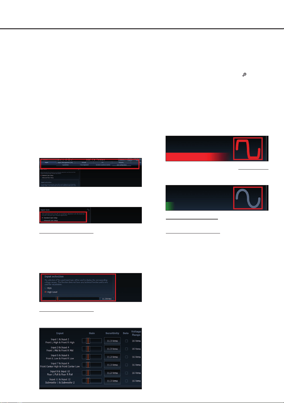
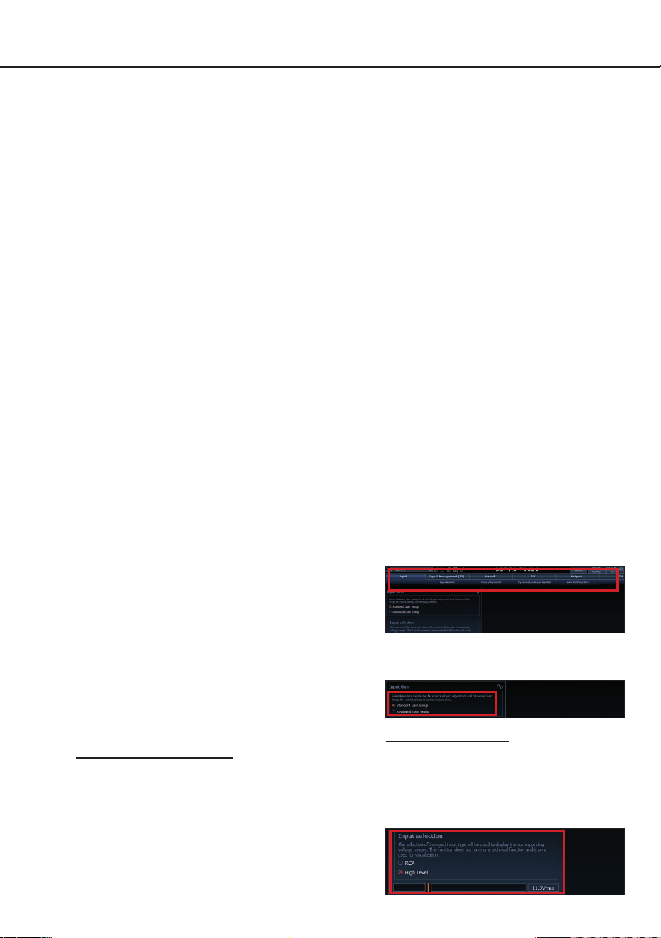
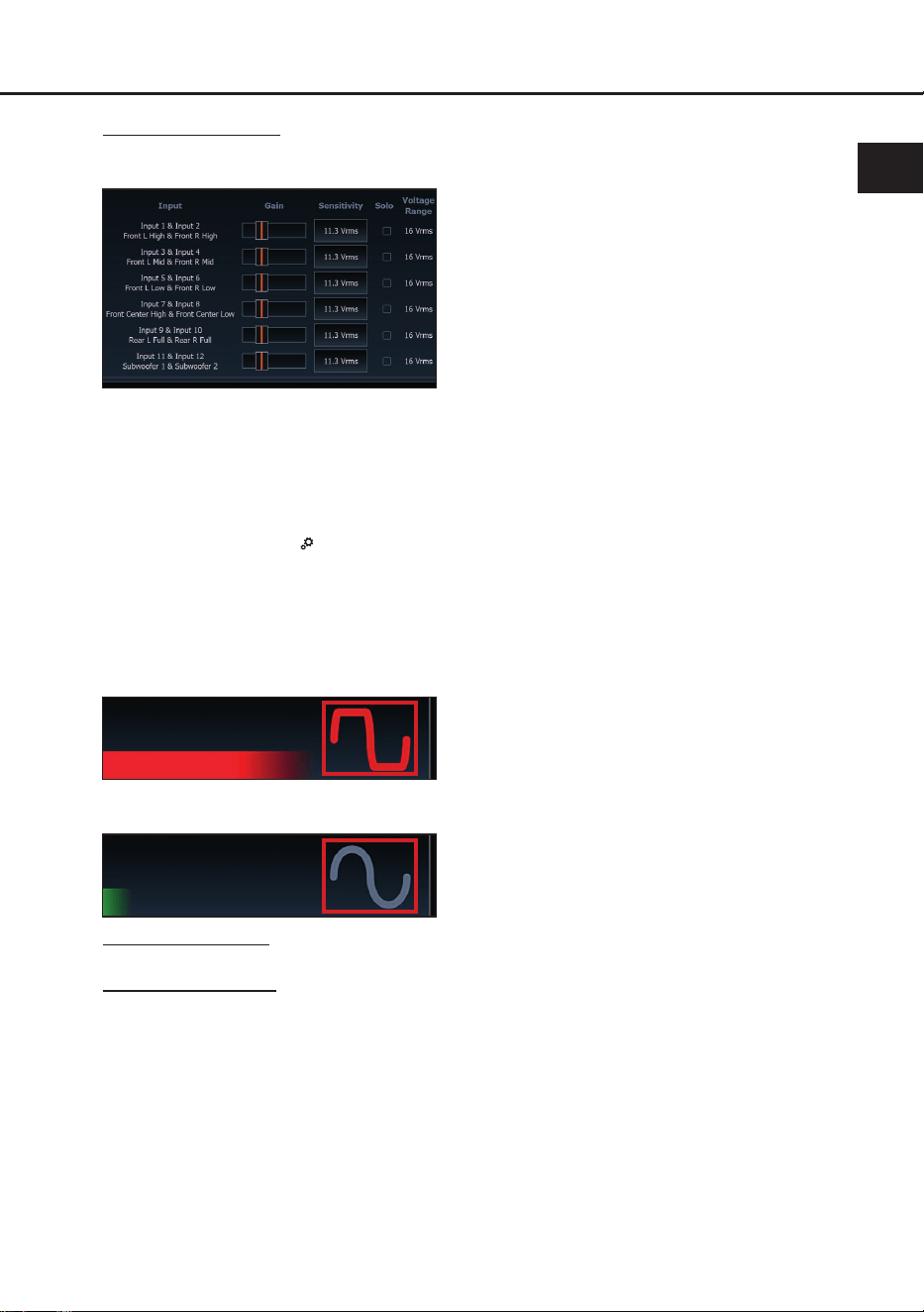
Muten Sie anschließend alle Signalaus-
gänge in der Software. Die Funktion nden
Sie im Tab „ Input“ im Unterpunkt „Gain
Conguration“.
2. Wählen Sie das Setupverfahren zur Ein-
stellung der Eingangsempndlichkeit aus.
Standard Gain Setup: Hier kann die Ein-
gangsempndlichkeit global für alle Kanäle
eingestellt werden (nur wählbar, wenn sich
alle Jumper in der Steckposition „Low Vol-
tage Range“ oder „High Voltage Range“
benden – siehe Seite 4, Punkt 1).
Advanced Gain Setup: Bei diesem Verfah-
ren ist eine individuelle Einstellung für die
einzelnen Kanalpaare möglich.
3. Stellen Sie die Lautstärke Ihres Radios auf
ca. 90 % der Gesamtlautstärke ein und
spielen Sie das dafür speziell entwickelte
„IGS - Input Gain Setup“ Signal ab. Dieses
nden Sie im DSP PC-Tool unter „Audio
Test Tracks“ (Startbildschirm →
).
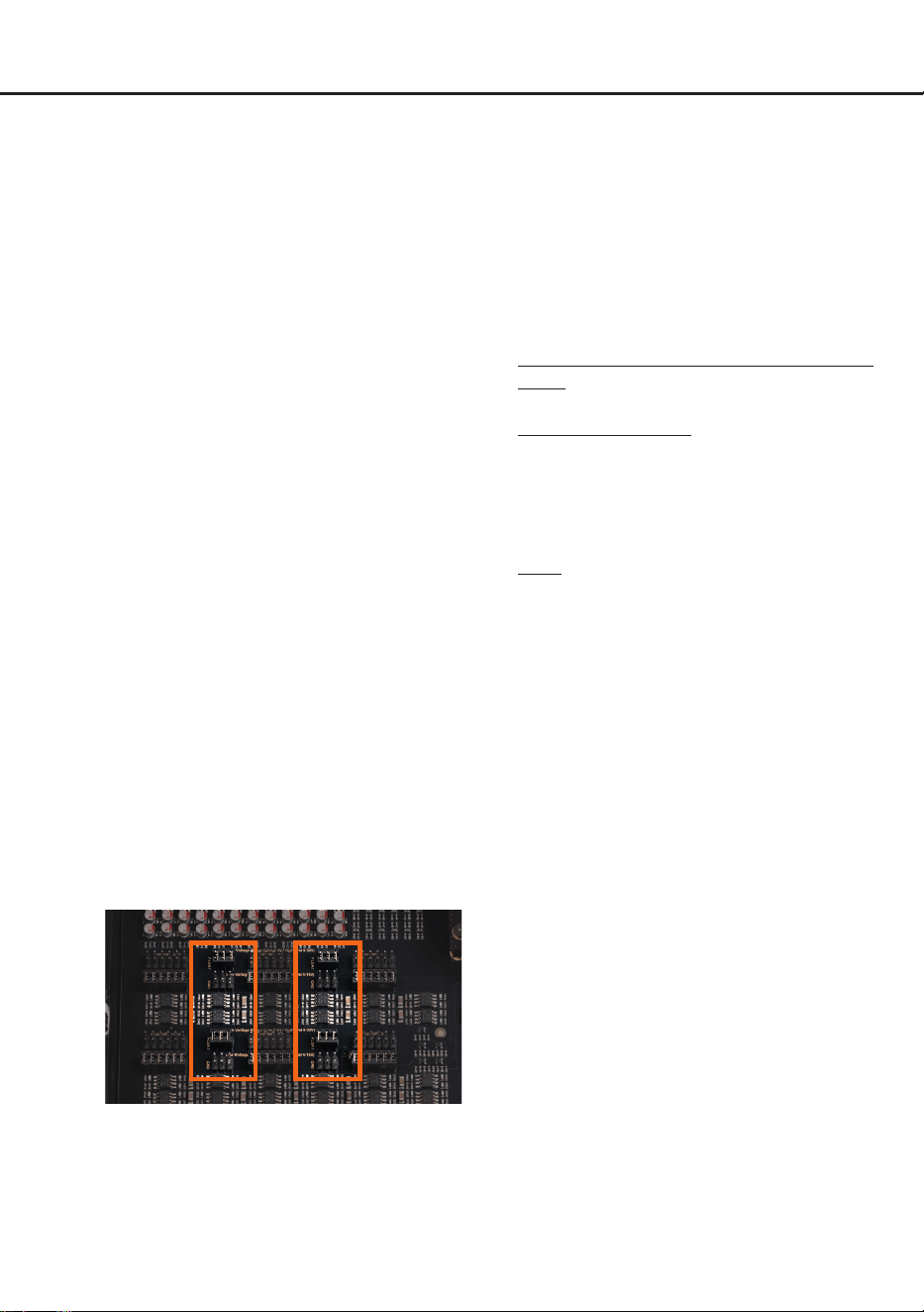
4. In der Regel ist die Clipping-Anzeige im
DSP PC-Tool aus (grau) und leuchtet nur
auf, wenn einer der analogen Signalein-
gänge übersteuert wird.
Erhöhen Sie nun die Eingangsempnd-
lichkeit mit Hilfe des Schiebereglers, bis
die Clipping-Anzeige rot aueuchtet (siehe
Markierung im folgenden Bild).
5. Schieben Sie nun den Regler einen Schritt
zurück, bis die Clipping-Anzeige wieder er-
lischt.
6. Standard Gain Setup: Der Vorgang ist
hiermit abgeschlossen.
Advanced Gain Setup: Wiederholen
Sie diesen Vorgang für jedes genutzte
Signaleingangspaar.
Verschiedene Einstellungsbeispiele für die
Eingangsempndlichkeit sind in der Tabelle
auf Seite 10 aufgeführt. Für weitere Anwen-
dungsfälle kontaktieren Sie bitte Ihren HELIX
Fachhändler.
9. Konguration des internen DSPs
WICHTIG: Vor der ersten Inbetriebnahme
wird dringend empfohlen, die grundlegenden
Einstellungen des Signalprozessors mit der
DSP PC-Tool Software vorzunehmen, um
Beschädigungen am Soundsystem zu ver-
meiden.
Nach dem Anschluss an einen PC können Sie
den Signalprozessor frei in der DSP PC-Tool
Software kongurieren. Nützliche Hinweise
zur korrekten Einstellung entnehmen Sie un-
serer Knowledge Base, welche auf unserer
Webseite bereitsteht.
Achtung: Es wird dringend empfohlen, zu
9
de
Beginn die Lautstärke am Radio auf Minimum
zu drehen und sämtliche Signalausgänge des
DSP ULTRA XT in der Software zu muten.
Speziell bei Verwendung in vollaktiven Syste-
men besteht sonst Zerstörungsgefahr für die
Lautsprecher.
10. Optional: Eingangssignal analysieren
Bei Verwendung des Highlevel-Eingangs
empfehlen wir, das Eingangssignal mit Hilfe
des Advanced Input Signal Analyzers (AISA)
der DSP PC-Tool Software auf werkseitig ein-
gestelltes Equalizing, Laufzeitkorrektur und
Allpass-Filter zu überprüfen und ggf. zu kor-
rigieren.
Dank der neuen PerfectStream-Funktion der
aktuellen ACO Plattform ist hierfür kein zu-
sätzliches Messequipment mehr erforderlich.
Die Messsignale werden direkt über die USB-
C Schnittstelle (Seite 3, Punkt 9) des Signal-
prozessors verlustfrei zum Computer über-
tragen. Informationen zum AISA nden Sie in
der umfangreichen Knowledge Base unserer
Webseite www.audiotec-scher.com.
11. Anschluss der Vorverstärkerausgänge
Die 16 Vorverstärkerausgänge (Line Output)
können Sie nun mit entsprechenden Kabeln
(RCA / Cinch-Kabel) mit den RCA / Cinch-
Eingängen der nachgeschalteten Verstärker
verbinden. Die Ausgänge liefern eine maxi-
male Ausgangsspannung von 8 Volt RMS.
Bei Verwendung einer dieser Ausgänge, ist es
zwingend erforderlich, den Remote-Ausgang
(Remote Out) zum Einschalten eines zusätz-
lich angeschlossenen Verstärkers zu verwen-
den, da ansonsten Störgeräusche auftreten
können.
12. Anschluss des Remote-Ausgangs
Der Remote-Ausgang dient zum prozessorge-
steuerten Einschalten der am Line Output an-
geschlossenen Verstärker. Verbinden Sie dazu
den Remote-Ausgang des DSP ULTRA XT mit
dem Remote-Eingang der Verstärker, um die
-
se über den DSP störungsfrei ein- und auszu-
schalten.
Der Ausgang aktiviert sich automatisch, sobald
der Bootvorgang des DSP abgeschlossen ist.
Zudem wird dieser Ausgang bei aktiviertem
„Power Save Mode“ und bei Betriebssoftware-
Updates abgeschaltet.
Wichtig: Verwenden Sie niemals ein anderes
Signal als den Remote-Ausgang, um einen an
-
geschlossenen Verstärker einzuschalten!
13. Sound Tuning
Nun können Sie Ihr Sound Setup erstellen.
Informationen rund um das Sound Tuning n-
den Sie in unserer umfangreichen Knowledge
Base auf www.audiotec-scher.de oder
kontaktieren Sie Ihren HELIX Fachhändler vor
Ort.
14. Optional: Anschluss des optischen Digital-
ausgangs im SPDIF-Format
Optischer, digitaler Stereo-Signalausgang im
SPDIF-Format (siehe Seite 3, Punkt 3) für den
Anschluss eines Verstärkers mit optischem
Digitaleingang. Der Ausgang hat eine „Sam-
pling Rate“ von 96 kHz / 24 Bit und liefert ein
lautstärkegeregeltes Signal.
Hinweis: Dieser Ausgang liefert ausschließ-
lich ein Stereosignal. Fader-Informationen
und Mehrkanal-Surround-Sound-Formate wie
Dolby oder DTS werden nicht unterstützt.
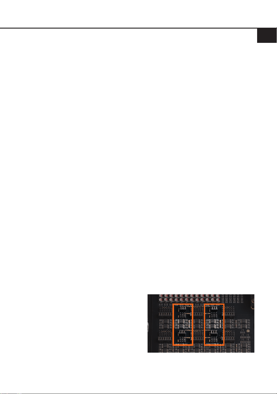
15. Optional: Konguration der Masseanbin-
dung der analogen RCA-Eingänge
In bestimmten Fällen kann es notwendig sein,
die Signalmasse der Signaleingänge anzu-
passen. Dies geschieht über die vier internen
Jumper (J7 bis J10).
Dazu muss der Signalprozessor geönet wer-
den. Lösen Sie die zwölf Inbusschrauben des
Bodenblechs und nehmen Sie dieses ab. Sie
haben nun Zugang zu den Jumpern.
J 7
J 8
J 9
J 10
Jeder Jumper stellt den Wertebereich für je-
weils zwei RCA-Eingangskanäle (Line Input)
ein.
10
Hardware-Konguration
Jumper 7 (J 7): Line Input 1 - 2
Jumper 8 (J 8): Line Input 3 - 4
Jumper 9 (J 9): Line Input 5 - 6
Jumper 10 (J 10): Line Input 7 - 8
Um die Position eines Jumpers zu ändern,
ziehen Sie ihn einfach nach oben ab und ste-
cken ihn in die gewünschte Position.
Achten Sie darauf, dass der Jumper vollstän-
dig und ohne Versatz eingesteckt ist.
Float (Werkseinstellung): In dieser Schalter-
stellung wird die Signalmasse durch einen
Dierenzverstärker von der Bordnetzmasse
getrennt.
Dies ist in den meisten Fahrzeugen die opti-
male Einstellung, um Störgeräusche, wie z. B.
von der Lichtmaschine, zu vermeiden.
GND: Die Signalmasse des Eingangs wird
direkt mit der Bordnetzmasse verbunden. Die-
se Einstellung sollte gewählt werden, wenn
bei der Schalterstellung „Float“ Störgeräusche
auftreten.
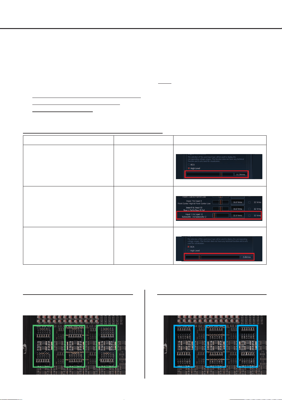
Abb. 1 – Low Voltage Range Konguration: Abb. 2 – High Voltage Range Konguration:
Für weitere Anwendungsfälle kontaktieren Sie bitte Ihren HELIX Fachhändler.
Wertebereich: Highlevel 4 - 16 Volt
Line (Cinch) 1 - 4 Volt
Wertebereich: Highlevel 8 - 32 Volt
Line (Cinch) 2 - 8 Volt
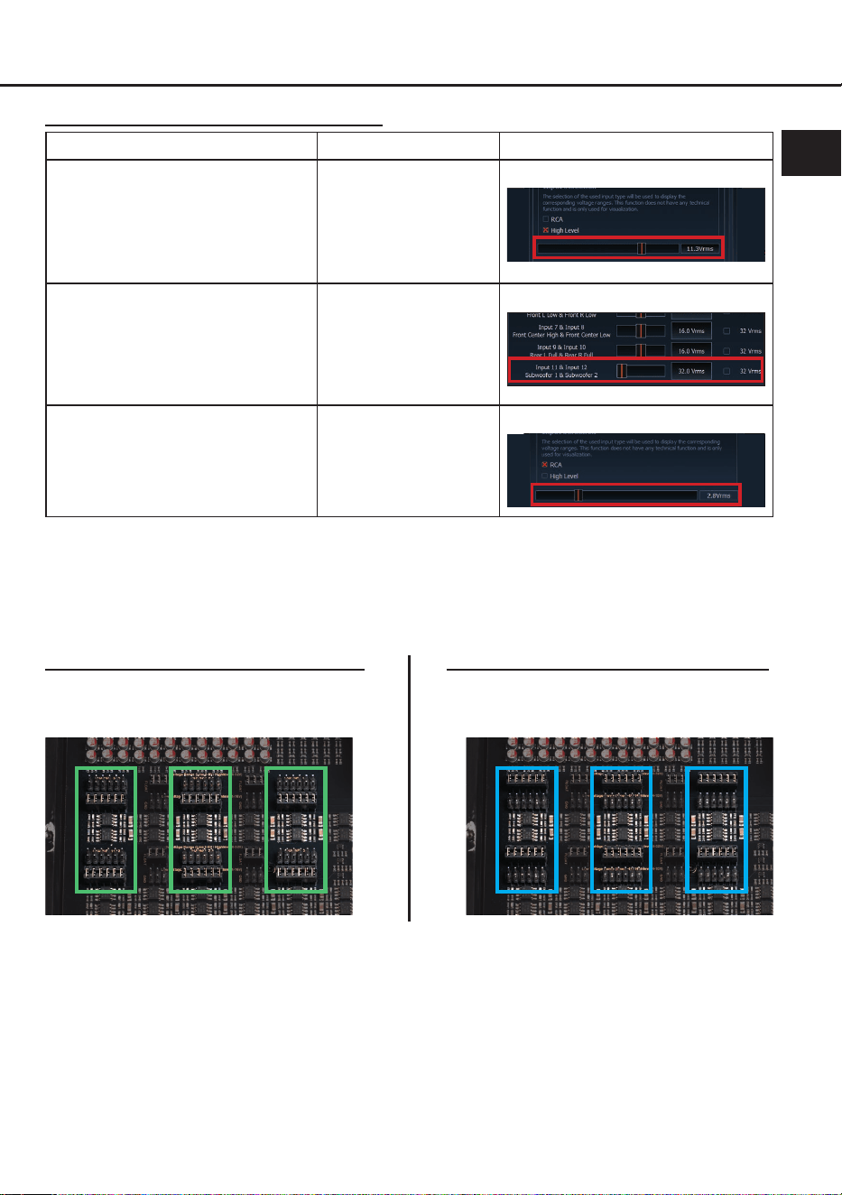
Einstellungsbeispiele für die Eingangsempndlichkeit:
Quelle Jumper positionen
Input Gain im DSP PC-Tool
Original-Radio 4- bis 6-kanalig
Bis 25 Watt Sinusleistung pro Kanal an
4 Ohm bzw. bis 50 Watt Sinusleistung
pro Kanal an 2 Ohm
Low Voltage Range –
Werkseitige Jumper-
positionen
(siehe Abb. 1)
Standard Gain Setup
Original-Radio mit Zusatzverstärker
4- bis 12-kanalig
Mehr als 25 Watt bis 200 Watt
Sinusleistung pro Kanal an 4 Ohm bzw.
bis zu 400 Watt an 2 Ohm oder 100 Watt
an 8 Ohm
High Voltage
Range oder
Mischkonguration
(siehe Abb. 2)
Advanced Gain Setup
Nachrüstradio 4- bis 6-kanalig mit
Vorverstärkerausgang
Bis zu einer maximalen RCA / Cinch
Ausgangsspannung von 4 Volt RMS
Low Voltage Range –
Werkseitige Jumper-
positionen
(siehe Abb. 1)
Standard Gain Setup
Hinweis: Idealerweise werden die Maximalspannungen der Signalquelle vor der Konguration der
Jumper gemessen und anschließend präzise pro Kanalpaar konguriert.
J 1
J 2
J 3
J 4
J 5
J 6
J 1
J 2
J 3
J 4
J 5
J 6
11
de
1. USB PerfectStream
Der HELIX NEXT DSP ULTRA XT verfügt über
die neue Generation der ACO Plattform mit
USB PerfectStream-Technologie. Diese erwei
-
tert den Signalprozessor um eine verlustfreie,
bidirektionale USB-Audio-Schnittstelle und er
-
möglicht die gleichzeitige Nutzung von Audio-
Streaming, AISA-Messung und DSP PC-Tool
Konguration über den integrierten USB-C
Eingang (Seite 3, Punkt 9).
Funktionen im Überblick:
- Verlustfreies High Resolution Audio-Strea
-
ming mit bis zu 192 kHz / 32 Bit
- Wiedergabe von Testtönen und Messsignalen
direkt vom Computer
- AISA-Messung ohne Zusatzhardware
(
Advanced Input Signal Analyzer – ermög-
licht die Analyse des Eingangssignals auf
werkseitig eingestelltes Equalizing, Hoch-
und Tiefpass- sowie Allpass-Filter)
Hinweis: Verbinden Sie das Gerät über das
mitgelieferte USB-C Kabel mit Ihrem PC oder
Smartphone. Die Erkennung erfolgt auto
-
matisch. Alle Smartphones oder Tablets mit
USB-C Anschluss werden ohne zusätzliche
Hardware unterstützt. Bei älteren Geräten
kann ggf. ein OTG-Kabel (Android) oder das
Apple Camera Connection Kit (iOS) erforder
-
lich sein. Die USB PerfectStream-Technologie
unterstützt alle gängigen Betriebssysteme wie
Windows 10 & 11, macOS, Android und iOS.
Hinweis: Der Musik-Streaming-Eingang des
USB PerfectStreams kann im „Signal Manage
-
ment (IO)“-Menü des DSP PC-Tools als eigene
Quelle konguriert werden.
2. SCP (Smart Control Port)
Dieser Multifunktionseingang (siehe Seite 3,
Punkt 10) dient zum Anschluss von HELIX
Zubehörprodukten, wie beispielsweise einer
Fernbedienung, mit deren Hilfe diverse Funk
-
tionen des Signalprozessors gesteuert werden
können.
Die Funktionalität muss je nach Typ der Fern
-
bedienung zuerst im „Remote Control“-Menü
der DSP PC-Tool Software oder an der Fern
-
bedienung selbst konguriert werden.
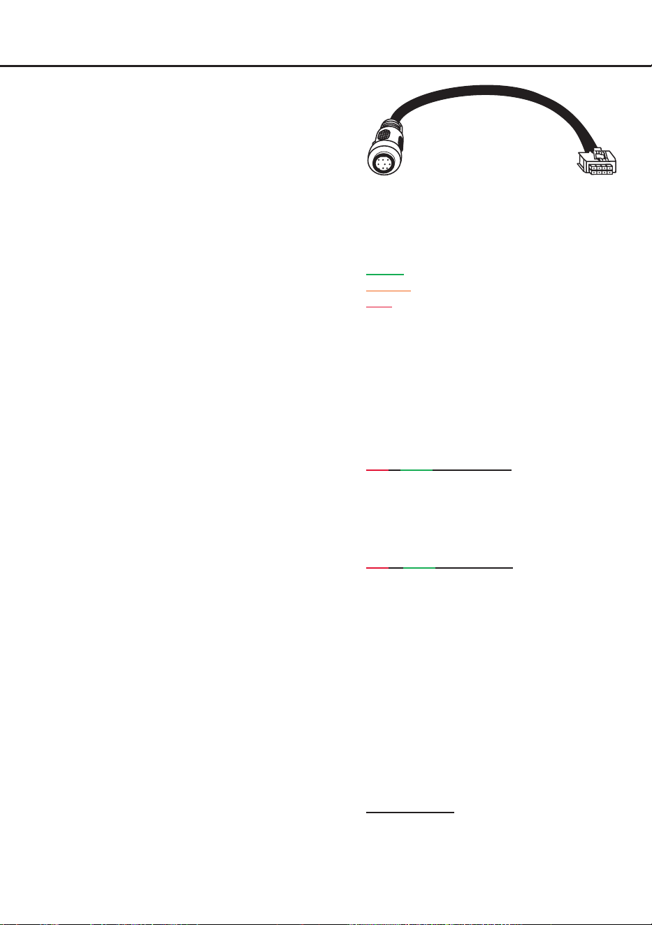
Achtung: Sofern das Zubehörprodukt keinen
SCP-Stecker besitzt, ist ein SCP-to-Control
Input Adapter (Art-Nr. M141313) optional bei
Ihrem Fachhändler erhältlich.
3. Status LED
Die Status LED (siehe Seite 3, Punkt 13) zeigt
den Betriebszustand des Signalprozessors
und dessen Speichers an.
Grün: Signalprozessor eingeschaltet und be
-
triebsbereit.
Orange: Power Save Modus aktiv.
Rot: Protection Mode aktiv. Dieser kann un
-
terschiedliche Ursachen haben. Der Signal-
prozessor ist mit Schutzschaltungen gegen
Über- und Unterspannung sowie Überhitzung
ausgestattet. Prüfen Sie in diesem Fall alle
Anschlüsse auf Fehler, wie z. B. Kurzschlüsse
oder fehlerhafte Verbindungen. Ist die Sicher
-
heitsschaltung der Temperaturüberwachung
aktiv, wird der Remote-Ausgang sowie die
Signalausgabe abgeschaltet, bis ein sicherer
Betrieb wieder gewährleistet werden kann.
Rot / grün langsam blinkend: Keine Betriebs
-
software auf dem DSP installiert. Verbinden
Sie den Signalprozessor mit der DSP PC-Tool
Software und bestätigen Sie das automatische
Update der Betriebssoftware. Die aktuellste
Version des DSP PC-Tools nden Sie auf
www.audiotec-scher.com.
Rot / grün schnell blinkend: Aktuell ausgewähl
-
ter Sound Setup-Speicherplatz ist leer. Ein
neues DSP Setup muss über die DSP PC-Tool
Software eingespielt werden oder schalten
Sie auf einen Speicherplatz mit vorhandenem
Sound Setup um.
4. Control-Taster
Der HELIX NEXT DSP ULTRA XT bietet 10
interne Speicherplätze für Sound Setups.
Mit Hilfe des Control-Tasters (siehe Seite 3,
Punkt 14) lässt sich zwischen zwei Speicher
-
plätzen umschalten. Diese können im DSP
PC-Tool festgelegt werden. Zudem kann durch
langes Drücken des Tasters ein Geräte-Reset
durchgeführt werden.
1. Setup-Wechsel: Taster 1 Sek. drücken.
SCP-to-Control Input Adapter
Weitere Funktionen

12
Werkseitig sind die Speicherbereiche eins und
zwei eingestellt. Der Umschaltvorgang wird
durch einmaliges rotes Blinken der Status LED
angezeigt. Alternativ kann zur Umschaltung
die optionale Fernbedienung URC.3 verwen
-
det werden. Um zwischen allen internen Spei-
cherplätzen umschalten zu können, ist optio-
nales Zubehör, wie z. B. die Fernbedienungen
DIRECTOR und CONDUCTOR notwendig.
2. Geräte-Reset: Taster länger als 5 Sek. ge
-
drückt halten. Durch ein Geräte-Reset wird
der interne Speicher auf die Werkseinstellung
zurückgesetzt! Dies wird durch ein durchge
-
hendes rotes Leuchten und grünes schnelles
Dauerblinken der Status LED angezeigt.
Achtung: Nach dem Zurücksetzen des Ge
-
rätes kann der DSP ULTRA XT keine Audio-
signale mehr wiedergeben, bis das Gerät mit
Hilfe des DSP PC-Tools aktualisiert wurde.
5. Clipping LED
In der Regel ist die LED aus und leuchtet nur
auf, wenn einer der analogen Signaleingänge
übersteuert wird.
An (rot): Einer der analogen Signaleingänge
wird übersteuert. Senken Sie die Eingangs
-
empndlichkeit ab, bis die LED erlischt. Wie
Sie die Eingangsempndlichkeit absenken, ist
auf Seite 7 unter Punkt 8 nachzulesen.
6. Masseschalter (GND Connection)
Beim HELIX NEXT DSP ULTRA XT ist die
Signalmasse galvanisch von der Bordnetz-
masse getrennt. Dies ist in den meisten
Fahrzeugen die beste Option, um Störge-
räusche wie z. B. von der Lichtmaschine zu
unterbinden. Allerdings gibt es auch Fälle, wo
die Massen der Eingänge mit den Ausgängen
direkt „hart“ oder über einen 200 Ohm Wider-
stand „weich“ verbunden werden müssen.
Der Masseschalter hat drei Positionen:
ISO:
Massen galvanisch getrennt
(Werkseinstellung).
GND: Massen „hart“ zusammengeschaltet.
200Ω: Massen „weich“ gekoppelt.
Weitere Funktionen
13
de
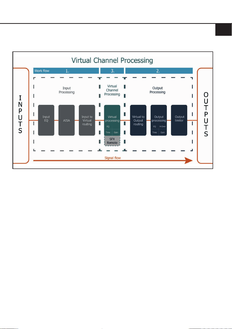
Virtual Channel Processing (VCP)
Das VCP erweitert den Umfang des Gerätes um eine Ebene an prozessierten Kanälen, welche sich zwischen
den Ein- und Ausgängen bendet. Insgesamt stehen acht zusätzliche prozessierte virtuelle Kanäle und
16 prozessierte Ausgangskanäle zur Verfügung.
Diese virtuelle Kanalebene bietet diverse Vorteile, gerade in komplexen Systemkongurationen.
Die Hauptvorteile dieses Konzeptes sind:
- Ausgangskanalübergreifender Gruppen-Equalizer
- Mehrwege-Konguration der DSP-Soundeekte (SFX)
- Zusätzliche Funktionen wie Rear Attenuation
Weiterführende Informationen zum VCP und dessen Konguration nden Sie in unserer Knowledge
Base auf www.audiotec-scher.de.
Der HELIX NEXT DSP ULTRA XT bietet das Virtual Channel Processing (VCP), ein mehrstuges
Signalverarbeitungskonzept, welches die perfekte Konguration komplexer Soundsysteme ermöglicht und
somit einzigartige Möglichkeiten des Klangtunings erönet.
14
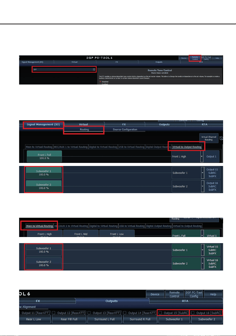
Zur Konguration einer Subwoofer-Fernbedienung müssen im DSP PC-Tool bestimmte Einstellungen
vorgenommen werden.
Zunächst muss die entsprechende Fernbedienung im Tab „Remote Control“ aktiviert und je nach Modell
konguriert werden.
Konguration einer Subwoofer-Fernbedienung
Die Subwoofer-Fernbedienung wirkt auf alle Ausgangskanäle, die im „Virtual to Output Routing“ mit
einem der beiden virtuellen Subwoofer-Signale versorgt werden („Subwoofer 1“ oder „Subwoofer 2“).
Dies kann jede beliebige Kombination an Ausgangskanälen sein.
Im nachfolgenden Beispiel sind es die Vorverstärkerausgänge / Line Outputs 15 und 16:
Hinweis: Bitte beachten Sie, dass den beiden virtuellen Subwoofer-Signalen „Subwoofer 1“ und / oder
„Subwoofer 2“ zuvor in den anderen Routing-Matrizen, z. B. „Main to Virtual“, ein Eingangssignal zuge-
wiesen werden muss.
Anschließend wird die Subwoofer-Regelung auch im „Outputs“ Menü hinter der Kanalbezeichnung als
[SubRC] angezeigt:

15
de
ACO Plattform-Features
Neben den einzigartigen DSP-Sound-
eekten bietet die ACO-Plattform des HELIX
NEXT DSP ULTRA XT zusätzlich eine Vielzahl an
System-Features.
Im „Device“-Menü der DSP PC-Tool Software kön-
nen für einige dieser System-Features individuelle
Einstellungen vorgenommen werden.
URC Setup Switch Conguration
Der ACO bietet Speicherplatz für zehn anstelle der
üblichen zwei Sound Setups.
Mit Hilfe einer optional erhältlichen URC Fernbe
-
dienung oder des Control-Tasters (siehe Seite 3,
Punkt 14) lässt sich zwischen zwei der zehn
Sound-Setup Speicherplätze umschalten. Diese
zwei Speicherplätze können in der „URC Setup
Switch Conguration“ festgelegt werden. Werk
-
seitig sind die Speicherbereiche eins und zwei
ausgewählt.
Um zwischen allen internen Speicher-
plätzen umschalten zu können, werden die optio-
nal erhältlichen Fernbedienungen DIRECTOR und
CONDUCTOR empfohlen.
Remote Output Conguration
An dieser Stelle kann festgelegt werden, ob der
Remote-Ausgang, der die angeschlossenen
Verstärker ein- bzw. ausschaltet, während eines
Sound-Setup-Wechselvorgangs kurzzeitig deakti-
viert werden soll. Standardmäßig ist dieses Fea-
ture aktiviert (ON).
Turn On & O Delay
Hier kann die Verzögerungszeit, mit welcher der
DSP ein- und ausgeschaltet werden soll, festge-
legt werden. Werkseitig sind 0,2 Sekunden einge-
stellt. Eine Änderung der Verzögerungszeit sollte
nur vorgenommen werden, wenn es beispielswei-
se zu Störgeräuschen beim Ein- und Ausschalten
des Signalprozessors kommt.
Power Save Mode
Diese Funktion ist standardmäßig aktiviert und
dient der Reduzierung der Leistungsaufnahme
des Soundsystems, wenn über einen bestimmten
Zeitraum kein Musiksignal erkannt wird.
Wird der Power Save Mode aktiv, schaltet sich
der Remote-Ausgang (Remote Out) automatisch
ab. Liegt anschließend wieder ein Musiksignal an,
kehrt das Gerät innerhalb von ca. 2 Sekunden in
den Normalbetrieb zurück.
Über die DSP PC-Tool Software kann die Funktion
ein- oder ausgeschaltet werden. Ist sie aktiviert,
lässt sich die Abschaltverzögerung im Bereich von
10 bis 600 Sekunden frei einstellen. Werkseitig
beträgt die Verzögerungszeit 60 Sekunden.
16
Einbau einer Extension Card 2.0
Durch die Installation einer Extension Card 2.0
(EC 2.0) lässt sich der Signalprozessor um zu-
sätzliche Schnittstellen erweitern – z. B. für High-
Denition Bluetooth
®
Audio-Streaming, zusätz-
liche analoge Eingänge und weitere Funktionen.
Zur Montage muss das Gerät geönet und die
Abdeckblende des EC 2.0-Slots ausgetauscht
werden.
Wichtig: Verwenden Sie ausschließlich für
dieses Gerät freigegebene EC 2.0 Module und
montieren Sie diese nur an der dafür vorgese-
henen Position. Falsche Module oder Einbau-
orte können zu Schäden am Signalprozessor,
der Extension Card, dem Radio oder weiteren
Komponenten führen.
Im folgenden Abschnitt nden Sie nun die wich-
tigsten Schritte zum Einbau und der ersten Inbe-
triebnahme einer Extension Card 2.0 (EC 2.0):
1. Verbindungen trennen
Trennen Sie alle Kabelverbindungen vom Gerät
.
2. Signalprozessor önen
Zum Önen des Gerätes lösen Sie zunächst
die zwölf Inbusschrauben des Bodenblechs
und nehmen dieses ab. Anschließend entfer-
nen Sie das Seitenblech mit dem EC 2.0-Slot,
nachdem Sie die sechs Schrauben (zwei In-
bus- und vier Kreuzschlitzschrauben) gelöst
haben.
3. Seitenblech vorbereiten
Entfernen Sie die Abdeckblende der EC 2.0
vom zuvor demontierten Seitenblech, indem
Sie die zwei Inbusschrauben auf der Rücksei-
te lösen.
Montieren Sie nun die neue, der EC 2.0 beilie-
gende Abdeckblende. Achten Sie auf korrekte
Ausrichtung und ziehen Sie die Schrauben
nur handfest an.
4. EC 2.0 vorbereiten
Bereiten Sie das Modul gemäß dessen Bedie-
nungsanleitung für den Einbau vor.
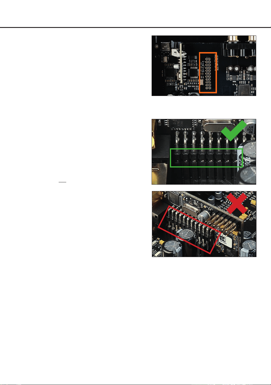
5. EC 2.0 in Signalprozessor einsetzen
Stecken Sie das Modul in den im Gerät vorge-
sehenen Sockel (siehe Markierung im nach-
folgenden Bild).
Achten Sie auf korrekten Sitz und vollstän-
digen Kontakt der Pins.
6. Signalprozessor wieder zusammensetzen
Montieren Sie das Seitenblech mit den sechs
Schrauben und danach das Bodenblech mit
den zwölf Schrauben.
7. EC 2.0 xieren
Verschrauben Sie das Modul mit dem Seiten-
blech. Details nden Sie in der Anleitung der
jeweiligen EC 2.0.
8. Inbetriebnahme
Schließen Sie alle Kabel wieder an und schal-
ten Sie das Gerät ein. Die EC 2.0 wird auto-
matisch erkannt, die grüne Info-LED leuchtet
auf.
9. Konguration im DSP PC-Tool
Die EC 2.0 kann nun über die DSP PC-Tool
Software konguriert werden.

17
de
Technische Daten
Eingänge ................................................................ 8 x Cinch
12 x Highlevel-Lautsprechereingang
1 x Optisch SPDIF (24 - 96 kHz)
1 x Koaxial SPDIF (24 - 192 kHz)
1 x Extension Card 2.0
1 x USB PerfectStream (44,1 - 192 kHz)
Eingangsempndlichkeit ......................................... Cinch: 1 - 8 Volt
Hochpegel: 4 - 32 Volt
Ausgänge ............................................................... 16 x Cinch
1 x Optisch SPDIF (96 kHz)
1 x Remote Out
Ausgangsspannung ................................................ 8 Volt
Frequenzbereich..................................................... 10 Hz - 44.000 Hz
DSP Auösung ....................................................... 64 Bit
DSP Rechenleistung ..............................................2 x 295 MHz (2,4 Mrd. MAC Operationen/Sek.)
Abtastrate ............................................................... 96 kHz
DSP Typ ................................................................. 2 x Audio Signalprozessor
Signalwandler ......................................................... ADC: ESS Technology ES9841Q mit HyperStream
®
IV Architektur und SABRE Technologie
DAC: ESS Technology ES9081Q mit HyperStream
®
IV Architektur und SABRE HIFI
®
Technologie
Signal- / Rauschabstand (A-bewertet @ 1 kHz) ..... Digitaleingang: 128 dB
Analogeingang: 116 dB
Klirrfaktor (THD+N @ 1 kHz) .................................. Digitaleingang: <= -110 dB / 0,0003 %
Analogeingang: <= -108 dB / 0,0004 %
Intermodulationsverzerrungen @ 1 kHz ................. Digitaleingang: <= -102 dB / 0,0008 %
Analogeingang: <= -102 dB / 0,0008 %
Übersprechen @ 10 kHz ........................................ > 100 dB
Betriebsspannung................................................... 9,6 - 18 Volt (max. 5 Sek. bis hinab zu 6 Volt)
Leistungsaufnahme ................................................ DC 12 V
1.2 A max.
Stromaufnahme ...................................................... 800 mA
Max. Remote-Ausgangsstrom ................................ 500 mA
Betriebstemperaturbereich ..................................... -40 °C bis +70 °C
Zusätzliche Features .............................................. Extension Card 2.0 Slot, Masseschalter, Smart
Control Port, 32 Bit CoProcessor, ADEP.3-
Schaltkreis, Auto Remote-Schalter, USB-C, USB
PerfectStream
Abmessungen (H x B x T) ......................................55 x 255.6 x 170 mm
18
Die gesetzlichen Mängelrechte des Käufers gegenüber dem Verkäufer bleiben durch diese Hinweise
unberührt. Schäden durch unsachgemäßen Einbau, fehlerhaften elektrischen Anschluss, Überlastung,
Spannungsspitzen im Fahrzeugbordnetz, nicht bestimmungsgemäße Verwendung, nicht vom Herstel-
ler freigegebene Veränderungen oder Nichtbeachtung dieser Bedienungsanleitung sind von über die
gesetzliche Mängelhaftung hinausgehenden Leistungen nicht umfasst. Für Serviceanfragen wenden
Sie sich bitte mit Kaufbeleg und Fehlerbeschreibung an Ihren Händler oder unseren Support. Zur Ver-
meidung von Transportschäden verwenden Sie bitte nach Möglichkeit die Originalverpackung oder eine
geeignete, transportsichere Verpackung. Technische Änderungen, Druckfehler und Irrtümer vorbehal-
ten. Zwingende gesetzliche Haftung bleibt unberührt.
Die Bluetooth
®
Wortmarke und die Logos sind eingetragene Warenzeichen der Bluetooth SIG, Inc. und
jegliche Nutzung dieser Marken durch die Audiotec Fischer GmbH geschieht unter Lizenz.
Andere Handelsmarken und Handelsnamen gehören den jeweiligen Inhabern.
Servicehinweis
Dieses Produkt ist mit einer CE-Kennzeichnung versehen. Damit erklärt die Audiotec
Fischer GmbH die Konformität mit den anwendbaren Harmonisierungsrechtsvorschriften
der Europäischen Union.
Dieses Symbol bedeutet, dass das Produkt nicht mit dem unsortierten Hausmüll entsorgt
werden darf. Geben Sie es am Ende seiner Lebensdauer bei einer dafür vorgesehenen
Sammel- oder Rücknahmestelle für Elektro- und Elektronikaltgeräte ab. Die ordnungsge-
mäße Entsorgung von Altgeräten trägt zur Vermeidung von Umwelt- und Gesundheitsschä-
den bei.
Dieses Produkt ist mit einer UKCA-Kennzeichnung versehen. Damit erklärt die Audiotec
Fischer GmbH die Konformität mit den anwendbaren Anforderungen des Vereinigten
Königreichs.
Dieses Produkt ist mit einer EAC-Kennzeichnung versehen. Damit erklärt die Audiotec
Fischer GmbH die Konformität mit den anwendbaren technischen Reglementen der Eura-
sischen Wirtschaftsunion (EAWU).
Markenzeichen
Entsorgungshinweis
Regulatorische Hinweise

19
en
General installation instructions for HELIX
components
To prevent damage to the unit and possible injury,
read this manual carefully and follow all installa-
tion instructions. This product has been checked
for proper function prior to shipping and is guaran-
teed against manufacturing defects.
Before starting your installation, disconnect
the battery’s negative terminal to prevent
damage to the unit, re and / or risk of injury.
For proper performance and to ensure full warran-
ty coverage, we strongly recommend having this
product installed by an authorized HELIX dealer.
Install your HELIX NEXT DSP ULTRA XT in a dry
location with sucient air circulation for proper
cooling of the equipment. The signal processor
should be secured to a solid mounting surface us-
ing proper mounting hardware. Before mounting,
carefully examine the area around and behind the
proposed installation location to ensure that there
are no electrical cables or components, hydraulic
brake lines or any part of the fuel tank located be-
hind the mounting surface. Failure to do so may
result in unpredictable damage to these compo-
nents and possible costly repairs to the vehicle.
General instructions for connecting the HELIX
NEXT DSP ULTRA XT
The signal processor may only be installed in vehi-
cles which have a 12 Volts negative terminal con-
nected to the chassis ground. Any other system
could cause damage to the signal processor and
the electrical system of the vehicle.
The positive cable from the battery for the entire
system should be provided with a main fuse at a
distance of max. 30 cm from the battery. The value
of the fuse is calculated from the maximum total
current draw of the car audio system and the cable
cross-section used.
Use only the provided connectors for connec-
tion of the DSP ULTRA XT. The use of other
connectors or cables can result in damage to
the signal processor, the head unit / radio or
the connected ampliers / loudspeakers!
Prior to installation, plan the cable routing to
avoid any possible damage to the wiring harness.
All cabling should be protected against pinching
or crushing hazards. Also avoid routing cables
close to potential noise sources such as electric
motors, high-power accessories and other vehicle
harnesses.
Congratulations!
General instructions
Dear Customer,
Congratulations on your purchase of this
innovative and high-qual ity HELIX product.
Thanks to more than 35 years of experience in
research and development of audio products, the
HELIX NEXT DSP ULTRA XT sets new standards
in the range of digital signal processors.
We wish you many hours of enjoyment with your
new HELIX NEXT DSP ULTRA XT.
Yours,
AUDIOTEC FISCHER
20
Connectors and control units
1
Lowlevel line inputs
Page 22, point 2
2
Digital inputs (Coaxial & Optical)
Page 22, point 4
3
Optical digital output
Page 26, point 14
.
4
Clipping LED
Page 29, point 5
5
Auto Remote switch
Page 23, point 5
6
Ground connection switch
Page 29, point 6
7
Power & Remote connector
Page 23, point 6
8
Highlevel speaker inputs
Page 22, point 3
9
USB-C input
Page 23, point 7 & Page 28, point 1
10
SCP (Smart Control Port)
Page 28, point 2
11
Extension Card 2.0 Slot
Page 33
12
Line outputs
Page 25, point 11
13
Status LED
Page 28, point 3
14
Control pushbutton
Page 28, point 4
9 1110 12
13 14
1 32 4
8
5 6 7
21
en
Hardware conguration
Congure the HELIX NEXT DSP ULTRA XT as
follows
Caution: Carrying out the following steps will re-
quire special tools and technical knowledge. In or-
der to avoid connection mistakes and / or damage,
ask your dealer for assistance if you have any
questions and follow all instructions in this manual
(see page 20). It is recommended that this unit be
installed by an authorized HELIX dealer.
1. Adjusting input voltage range of the analog
signal inputs
Before proceeding to adjust the input volt-
age range, please take note of the following
guidelines. This adjustment is only necessary
when connecting devices from the following
categories:
- Aftermarket radios with a Line (RCA) out-
put voltage exceeding 4 V RMS
- Factory sound system ampliers with an
output voltage exceeding 16 V (see the
conguration examples on page 27)
For standard applications, such as connect-
ing:
- Factory radios
- Aftermarket radios with a maximum Line
(RCA) output voltage of 4 V RMS
this adjustment is not required. In such cas-
es, you can proceed directly to point 2 on
page 22.
To set the input voltage range, follow these
steps:
a. Open the signal processor
Loosen the twelve Allen screws of the bot-
tom plate and remove it.
b. Determine the output voltage of the
signal source
We recommend measuring the maximum
output voltage using an appropriate mea-
suring device, such as the Audiotec Fischer
AMI, or contacting your authorized HELIX
dealer. If you are unsure, we recommend
setting all 6 jumpers (J1 to J6) to the “High
Voltage Range” (Line 2 - 8 V / Highlevel
8 - 32 V) to avoid potential damage to the
device. To do this, all jumpers (J1 - J6) must
be moved to the factory-unused multi-pin
connectors, as shown in gure 2.
c. Place the jumpers in the corresponding
voltage range
To change the jumper’s position, simply lift
it upwards and insert it into the desired po-
sition. Ensure that the jumper is fully insert-
ed and not oset.
Overview of jumper plug-in positions:
The DSP ULTRA XT has six 12-pin jumpers
(J1 to J6) for adjusting the Voltage Range.
Each jumper sets the range for one analog
input channel pair.
Low voltage range conguration
( factory setting / see g. 1):
Value range: Highlevel 4 - 16 Volts
Line (RCA) 1 - 4 Volts
High voltage range conguration
(see g. 2):
Value range: Highlevel 8 - 32 Volts
Line (RCA) 2 - 8 Volts
Figure 1:
J 1
J 2
J 3
J 4
J 5
J 6
Figure 2:
J 1
J 2
J 3
J 4
J 5
J 6
d. Reassemble the signal processor
After completing the adjustment, fully reas-
semble the signal processor.

22
Hardware conguration
2. Connecting the line inputs
These eight lowlevel line inputs (Line Input)
can be connected to signal sources such as
head units / car radios or factory-installed am-
pliers using appropriate cables. Each input
can be assigned to any output using the DSP
PC-Tool software. Input sensitivity is facto-
ry-set to 2.8 Volts for all channels.
The available adjustment range depends on
the previously selected “Voltage Range” (see
page 21, point 1 “Adjusting the input voltage
range”) and is 1 to 8 Volts in total.
The adjustment is carried out using the DSP
PC-Tool software (see page 24, point 8).
The automatic turn-on circuit does not work
when using the line inputs. In this case the re-
mote input (Remote In) has to be connected to
activate the DSP ULTRA XT.
Important: It is strictly forbidden to use the
highlevel speaker input and lowlevel line input
of an individual channel at the same time as
this may cause severe damage to the con-
nected signal source. Nevertheless, it is pos-
sible to use the highlevel input of one channel
and the lowlevel line input of another channel
simultaneously.
3. Connecting the highlevel speaker inputs
The 12 highlevel speaker inputs (Highlevel
Input) can be connected directly to the loud-
speaker outputs of a factory radio, aftermar-
ket radio or factory-installed amplier using
appropriate cables (loudspeaker cables with
1 mm² / AWG 18 max.).
We recommend the following channel assign-
ment if a common car radio will be connected
to the signal processor:
Channel A = Front left
Channel B = Front right
Channel C = Rear left
Channel D = Rear right
It is not mandatory to use all high level speak-
er inputs. If only two channels are connected,
we recommend using channels A and B. Make
sure that the polarity is correct. If one or more
connections have reversed polarity it may af-
fect the performance of the signal processor.
If this input is used the remote input (Remote
In) does not need to be connected as the sig-
nal processor will automatically turn on once a
loudspeaker signal is received.
Input sensitivity is factory-set to 11.3 Volts for
all channels.
The available adjustment range
depends on the previously selected “Voltage
Range” (see page 21, point 1 “Adjusting the
input voltage range”) and is 4 to 32 Volts in
total
.
The adjustment is carried out using the
DSP PC-Tool software (see page 24, point 8).
Attention: Only use the supplied connectors
to connect the highlevel speaker inputs.
Important: It is strictly forbidden to use the
high level speaker input and lowlevel line input
of an individual channel at the same time as
this may cause severe damage to the con-
nected signal source.
Nevertheless, it is possible to use the highlevel
speaker input of one channel and the lowlevel
line input of another channel simultaneously.
4. Connecting a digital signal source in
SPDIF format
If you have a signal source with coaxial or op-
tical digital output, it can be connected to the
signal processor. The sampling rate must be
between 24 and 96 kHz for the optical input
and between 24 and 192 kHz for the coaxial
input. The input signal is automatically adapt-
ed to the internal sampling rate.
In the standard conguration the manual acti-
vation of the optical digital input via an option-
al remote control is congured. Alternatively
the activation of the digital inputs can be con-
gured in the DSP PC-Tool software under the
“Signal Management (IO)” tab in the “Source
Conguration” section.
The automatic turn-on circuit does not work
when the digital input is used. Therefore it
is mandatory to connect the remote input
( Remote In).
Important: Digital audio signals typically do
not contain volume level information. Keep
in mind that this will lead to full level on the
outputs of the DSP ULTRA XT and your con-
nected ampliers.
This may cause severe damage to your
speakers. We strongly recommend using an
optional remote control for adjusting the vol-
ume level of the digital signal inputs!

23
en
Note: The DSP ULTRA XT can only handle
uncompressed digital stereo signals in PCM
format with a sample rate between 24 kHz and
96 kHz for the optical input or between 24 kHz
and 192 kHz for the coaxial input.
5. Conguration of the remote input
The DSP ULTRA XT will be turned on auto-
matically if the highlevel speaker input (High-
level Input) is used or if a signal is applied to
the remote input terminal (Remote In, see
page 20, point 7). The Auto Remote switch
(see page 20, point 5) allows you to deactivate
the automatic turn-on feature of the highlevel
speaker inputs. The feature should be deacti-
vated if there are e.g. noises while switching
on / o the signal processor.
On: Activation via highlevel speaker input is
enabled (factory setting).
O: Activation via highlevel speaker input is
disabled.
Note: If the automatic turn-on function is de-
activated it is mandatory to use the remote
input terminal to power up the signal proces-
sor! The highlevel signal will be ignored in this
case.
6. Connection to power supply & remote
ATTENTION: Make sure to disconnect the
battery before installing the DSP ULTRA XT!
Use only the included screw-type terminal to
connect the signal processor to a power sup-
ply. Make sure of correct polarity.
+: Connector for the +12 V power cable. The
positive wire has to be connected to the bat-
tery’s positive terminal or a power distribution
block. Though the current draw of the signal
processor is rather low (approx. 800 mA) we
recommend a minimum wire gauge of 1 mm² /
AWG18.
–: Connector for the ground cable. The ground
wire must be connected to the vehicle chassis
at a non-insulated point or directly to the neg-
ative terminal of the vehicle battery. The cable
should have the same gauge as the +12 V
wire. Inadequate grounding causes audible
interference and malfunctions.
Remote In: The remote input (see page 20,
point 7) is used to switch the signal processor
on and o if the signal source connected to
the Highlevel Input does not activate the auto-
matic turn-on function, if the digital inputs are
used, or if the signal processor should deliber-
ately be controlled only via a remote signal. To
do this, connect the signal processor’s remote
input to the remote output / automatic antenna
(aerial positive) output of the head unit / car
radio. Thus the signal processor is switched
on and o together with the head unit.
We do not recommend controlling the remote
input via the ignition switch to avoid popping
noises during turn-on / turn-o.
Note: This input does not need to be connect-
ed if one of the highlevel inputs is used. To de-
activate the “automatic turn-on” function read
the description in point 5 “Conguration of the
remote input”.
Remote Out: The remote output (see page 20,
point 7) is used for turning on / o ampliers
that are connected to the Line Outputs of the
DSP ULTRA XT. Therefore connect the re-
mote output of the DSP to the remote inputs
of your ampliers to switch them on and o via
the DSP without interfering signals. The re-
mote output is activated automatically as soon
as the booting process of the DSP is complet-
ed. Additionally this output will be turned o
during the “Power Save Mode” or a software
update process.
IMPORTANT: Never use a dierent signal
than the remote output of the DSP to activate
connected ampliers!
7. Connecting the PC & rst start-up
The USB-C input enables the DSP ULTRA XT
to be connected to a personal computer and
congured with our DSP PC-Tool software us-
ing the provided USB-C cable. If your comput-
er only has a USB-A port, use the USB-C to
USB-A adaptor also supplied.
Please note: It is not possible to connect any
USB storage devices.
Before you connect the signal processor to
a computer for the rst time, download the
latest DSP PC-Tool software (at least ver-
sion 6) from our homepage. The software
and a comprehensive knowledge base can be
found at www.audiotec-scher.com.
It is advisable to check regularly for software
updates so that the device is always up to
24
Hardware conguration
date. We strongly recommend carefully read-
ing the DSP PC-Tool knowledge base before
using the software for the rst time in order to
avoid any complications and failures.
Important: Make sure that the DSP is not
connected to your computer before the soft-
ware and USB driver are installed!
The most important steps for connection and
initial start-up are described below:
1. Download the latest version of the DSP
PC-Tool software (available on our web-
site www.audiotec-scher.com) and in-
stall it on your computer.
2. Connect the signal processor to your com-
puter using the USB cable that is included
in the delivery. If you have to bridge longer
distances please use an active USB exten-
sion cable with integrated repeater.
3. First turn on the signal processor and then
start the software. The operating software
will be updated automatically to the latest
version if it is not up-to-date.
8. Adjustment of the input sensitivity of the
analog signal inputs
ATTENTION: It is mandatory to properly adapt
the input sensitivity of the DSP ULTRA XT to
the signal source in order to achieve the best
possible signal quality and to avoid damage
to the signal processor. It is also mandatory
to adjust the “Voltage Range” to the output
voltage of your signal source (see page 21,
point 1).
The input sensitivity of each channel pair can
be optimally adjusted to the signal source us-
ing the DSP PC-Tool software.
The setting aects both the lowlevel and the
highlevel inputs!
The gain control ranges are:
Low Voltage Range conguration:
Highlevel: 4 - 16 Volts
Line (RCA / Cinch): 1 - 4 Volts
High Voltage Range conguration:
Highlevel: 8 - 32 Volts
Line (RCA / Cinch): 2 - 8 Volts
Input sensitivity is factory-set to 11.3 Volts
(highlevel) and 2.8 Volts (Line / RCA / Cinch).
This value serves as the optimal basic setting
and must be adjusted as described below.
If the signal source provides a lower output
voltage, the input sensitivity can be increased
via the DSP PC-Tool.
If your signal source delivers a higher output
voltage – for example, if a factory-installed
amplier serves as signal source – the input
sensitivity must be lowered and the correct
conguration of the “Voltage Range” jumpers
must be checked (see page 21, point 1).
If you are not sure regarding the signal
source’s output voltage, please contact your
HELIX specialist dealer.
Note: Do not connect any ampliers to the
outputs of the signal processor during this
setup.
To adjust the input sensitivity, please follow
the steps below:
1. Connect the DSP to a computer and start
the DSP PC-Tool software (see page 23,
point 7). Then mute all signal outputs of the
signal processor in the software. The func-
tion can be found in the “Input” tab in the
sub-menu “Gain Conguration”.
2. Select the setup method to adjust the input
sensitivity.
Standard Gain Setup: This method allows
for global adjustment of input sensitivity for
all input channels (can only be selected
if all jumpers are set to the “Low Voltage
Range” or “High Voltage Range” position –
see page 21, point 1).
25
en
Advanced Gain Setup: This method allows
individual conguration of each channel
pair.
3. Set the volume of your head unit to approx-
imately 90 % of the maximum volume and
play the specially developed “IGS - Input
Gain Setup” signal. You can nd this sig-
nal in the DSP PC-Tool under “Audio Test
Tracks” (home screen →
).
4. Normally, the clipping indicator in the DSP
PC-Tool is o (gray) and only lights up if
one of the analog inputs is overdriven.
Now increase the input sensitivity using the
slider until the clipping indicator lights up
red (see the following picture).
5. Then move the slider back one step until
the clipping indicator turns o again.
6. Standard Gain setup: The process is now
complete.
Advanced Gain setup: Repeat this process
for each input channel pair used.
Various adjustment examples of the input
sensitivity can be found on page 27. For
further applications, please contact your
HELIX specialist dealer.
9. Conguration of the internal DSP
IMPORTANT: The general signal proces-
sor settings should be congured with the
DSP PC-Tool software before initial start-up
to prevent damage to the sound system. Af-
ter connecting the device to a PC, the signal
processor can be congured in the DSP PC-
Tool. Useful information for proper congura-
tion can be found in our knowledge base at
www.audiotec-scher.com.
Caution: We highly recommend setting the
volume of your car radio to the minimum posi-
tion and muting all signal outputs. Especially if
the DSP ULTRA XT is used in fully active ap-
plications, an incorrect setup can immediately
destroy your speakers.
10. Optional: Analyzing the input signal
When using highlevel signals, we recommend
analyzing the input signal with the Advanced
Input Signal Analyzer (AISA) in the DSP PC-
Tool. This helps detect and correct factory-set
equalization, time alignment, or allpass lters
if present.
Thanks to the new PerfectStream function
of the current ACO platform, no additional
measuring equipment is required for this. The
measurement signals are transmitted directly
to the computer without loss via the USB-C
interface (see page 20, point 9) of the signal
processor. Information on the AISA can be
found in the extensive Knowledge Base on
our website www.audiotec-scher.com.
11. Optional
: Connecting the line outputs
The 16 line outputs (see page 20, point 12)
can be connected to the RCA / Cinch inputs of
the external ampliers using appropriate ca-
bles (RCA / Cinch cables).
The outputs provide a maximum output volt-
age of 8 Volts RMS. When using one of these
outputs, it is essential to use the remote output
to switch on an additionally connected ampli-
er, as otherwise interference noise may occur.
12. Optional: Connecting the remote output
The remote output is used for turning on / o
ampliers that are connected to the line out-
puts of the DSP ULTRA XT. Therefore connect
the remote output of the DSP ULTRA XT to the
remote input of your ampliers to switch them
on and o via the DSP without interfering sig-
nals. The remote output is activated automat-
ically as soon as the booting process of the
DSP is completed. Additionally this output will
be turned o during the “Power Save Mode” or
26
Hardware conguration
a software update process.
Important: Never use a dierent signal than
the remote output of the DSP ULTRA XT to
activate a connected amplier!
13. Sound tuning
Now you can create your sound setup.
Information about sound tuning can be
found in our extensive knowledge base at
www.audiotec-scher.com or contact your
local HELIX dealer.
14. Optional: Connecting the optical digital
output in SPDIF format
Optical digital stereo signal output in SPDIF
format for connecting an amplier with optical
digital input. The output has a sampling rate
of 96 kHz / 24 Bit and provides a volume-con-
trolled signal.
Note: This output provides a stereo signal
only. Fader information and multi-channel sur-
round sound formats such as Dolby or DTS
are not supported.
15. Optional: Conguring the ground connec-
tion of the analog RCA inputs
In some cases, it may be necessary to adjust
the signal ground of the signal inputs. This is
done using the four internal jumpers (J7 to
J10).
To do this, the signal processor must be
opened. Loosen the twelve Allen screws of
the bottom plate and remove it. You now have
access to the jumpers.
J 7
J 8
J 9
J 10
Each jumper sets the range for two RCA input
channels (Line Input).
Jumper 7 (J 7): Line Inputs 1 - 2
Jumper 8 (J 8): Line Inputs 3 - 4
Jumper 9 (J 9): Line Inputs 5 - 6
Jumper 10 (J 10): Line Inputs 7 - 8
To change the jumper’s position, simply lift it
upwards and insert it into the desired position.
Ensure that the jumper is fully inserted and not
oset.
Float (factory setting): In this switch position,
the signal ground is separated from the ve-
hicle’s ground by a dierential amplier. This
is usually the best setting in most vehicles to
prevent interference noise, e.g. from the alter-
nator.
GND: The signal ground is tied together with
the vehicle’s ground. This setting should be
selected if noise occurs in the “Float” position.
27
en
Examples for adjusting the input sensitivity:
Source Jumper positions
Input Gain in DSP PC-Tool
4- to 6-channel factory radio
Up to 25 Watts RMS power per channel
at 4 Ohms or up to 50 Watts RMS power
at 2 Ohms
Low Voltage Range –
default jumper positions
(see g. 1)
Standard Gain Setup
Factory radio with additional 4- to
12-channel amplier
>25 Watts and up to 200 Watts RMS
power per channel at 4 Ohms or up to
400 Watts RMS at 2 Ohms or 100 Watts
RMS at 8 Ohms
High Voltage Range or
mixed conguration
(see g. 2)
Advanced Gain Setup
4- to 6-channel aftermarket radio
with pre-amplier outputs
Up to a maximum RCA / Cinch output
voltage of 4 Volts RMS
Low Voltage Range –
default jumper positions
(see g. 1)
Standard Gain Setup
Fig. 1 – Low Voltage Range conguration: Fig. 2 – High Voltage Range conguration:
For further applications, please contact your HELIX specialist dealer.
Value range: Highlevel 4 - 16 Volts
Line (RCA) 1 - 4 Volts
Value range: Highlevel 8 - 32 Volts
Line (RCA) 2 - 8 Volts
Note: Ideally, the maximum voltages of the signal source should be measured before conguring the
jumpers and then congured precisely for each channel pair.
J 1
J 2
J 3
J 4
J 5
J 6
J 1
J 2
J 3
J 4
J 5
J 6
28
1. USB PerfectStream
The HELIX NEXT DSP ULTRA XT features
the new generation of the ACO platform with
USB PerfectStream technology. This extends
the signal processor with a lossless, bidirec-
tional USB audio interface and enables the
simultaneous use of audio streaming, AISA
measurement and DSP PC-Tool conguration
via the integrated USB-C input (see page 20,
point 9).
Functions at a glance:
- Lossless high-resolution audio streaming
with up to 192 kHz / 32 Bit
- Playback of test tones and measurement
signals directly from the computer
- AISA measurement without additional mea-
suring equipment (Advanced Input Signal
Analyzer – enables analysis of the input sig-
nal for factory-set equalizing, highpass, low-
pass and all-pass lters).
Note: Connect the device to your PC or smart-
phone using the USB-C cable supplied. The
device is automatically detected. All smart-
phones or tablets with USB-C connection are
supported without additional hardware. An
OTG cable (Android) or the Apple Camera
Connection Kit (iOS) may be required for old-
er devices. The USB PerfectStream technol-
ogy supports all common operating systems
such as Windows 10 & 11, macOS, Android
and iOS.
Note: The music streaming input of the USB
PerfectStream can be congured as a sepa-
rate source in the “Signal Management (IO)”
menu of the DSP PC-Tool.
2. SCP (Smart Control Port)
This multi-functional input (see page 20,
point 10) is used to connect HELIX accesso-
ry products, such as a remote control, which
allows the user to adjust several features of
the signal processor. Depending on the type
of remote control, its functionality must rst be
dened in the “ Remote Control” menu of the
DSP PC-Tool software.
Attention: If the accessory product does not
have an SCP connector, a SCP-to-Control
Input adaptor (Art-no. M141313) is optionally
available from your specialist dealer.
3. Status LED
The Status LED (see page 20, point 13) indi-
cates the operating mode of the signal pro-
cessor and of its memory.
Green: DSP is ready for operation.
Orange: Power Save Mode is active.
Red: Protection Mode is active. This may have
dierent root causes. The DSP ULTRA XT is
equipped with protection circuits against over-
and undervoltage as well as overheating.
Please check for connection errors such as
short-circuits or other incorrect connections. If
the signal processor is overheated the inter-
nal temperature protection switches o the re-
mote and signal output until it reaches a safe
temperature level again.
Red / green slow ashing: No operating soft-
ware installed. Connect the signal processor
to the DSP PC-Tool software and conrm the
automatic update of the operating software.
You will nd the latest version of the DSP PC-
Tool software at www.audiotec-scher.com.
Red / green fast ashing: The currently se-
lected sound setup memory is empty. A new
setup has to be loaded via the DSP PC-Tool
software or switch to a memory position with
existing sound setup.
4. Control pushbutton
The HELIX NEXT DSP ULTRA XT provides
10 internal memory locations for sound set-
ups. The Control pushbutton (see page 20,
point 14) allows the user to switch between
two memory positions. These can be dened
in the DSP PC-Tool. In addition a device reset
can be performed by pressing the button for a
longer period.
1. Setup switch: Press Control pushbutton for
1 second. The memory locations one and two
are dened by default. Switching is indicated
by a single red ash of the Status LED. Al-
ternatively, the optional URC.3 remote control
can be used for switching. To switch between
SCP-to-Control Input adaptor
Additional functions

29
en
all internal memory locations, optional acces-
sories like the DIRECTOR display remote
control or CONDUCTOR are required.
2. Device reset: Press pushbutton for ve
seconds. This completely erases the internal
memory and is indicated by a continuous red
light and constant green ashing of the Status
LED.
Attention: After erasing the setups from
memory the DSP ULTRA XT will not output
any audio signal until the device is updated
via the DSP PC-Tool software.
5. Clipping LED
Normally, the Clipping LED is o and only lights
up if one of the analog inputs is overdriven.
On (red): One of the analog signal inputs is
overdriven. Reduce the input sensitivity until
the LED goes out. Instructions on how to re
-
duce the input sensitivity are described on
page 24, point 8.
6. GND Connection switch
The signal ground of the HELIX NEXT
DSP ULTRA XT is galvanically decoupled
from the power ground. In many cars this set-
up is the best way to avoid alternator noise.
Nevertheless, there are use cases where it
will be necessary to directly connect input and
output ground or to tie both grounds together
via a resistor. Therefore the GND Connection
switch (see page 20, point 6) has three po-
sitions:
ISO: Input and output ground separated
(factory setting).
GND: Input and output ground tied together.
200Ω: Input and output ground connected via
200 Ohms resistor.
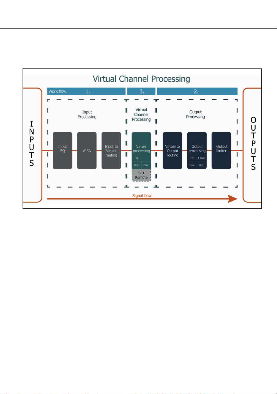
30
Virtual Channel Processing (VCP)
The VCP extends the scope of the device by an additional layer of processed channels, which is located
between the inputs and outputs. A total of eight additional processed virtual channels and 16 processed
output channels are available.
This virtual channel layer oers several advantages, especially in complex system congurations.
The main advantages of this concept are:
- Cross-channel group equalizers that aect several output channels simultaneously
- Multi-way speaker conguration of DSP sound eects (SFX)
- Additional features such as Rear Attenuation
For further information on the VCP and its conguration, please refer to our Knowledge Base at
www.audiotec-scher.com.
The HELIX NEXT DSP ULTRA XT oers Virtual Channel Processing (VCP), a multi-stage signal
processing concept that enables the perfect conguration of complex sound systems, opening up
completely new possibilities for sound tuning.
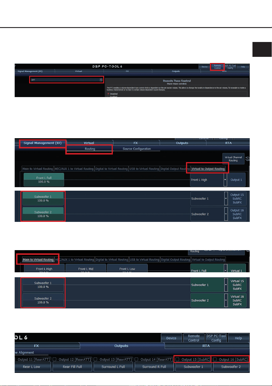
31
en
Conguration of a subwoofer remote control
In order to congure a subwoofer remote control, specic settings have to be made in the DSP PC-Tool.
First, the appropriate remote control must be activated in the “Remote Control” tab and then congured,
depending on the model.
The subwoofer remote control is tied to the output channels that are supplied with one of the two virtual
subwoofer signals (“Subwoofer 1” or “Subwoofer 2”) in the “Virtual to Output Routing” matrix. This can
be any combination of output channels.
In the following example these are the pre-amplier outputs / Line Outputs 15 and 16:
Note: Please note that an input signal must be assigned to “Subwoofer 1” and / or “Subwoofer 2” in the
other routing matrices, such as the “Main to Virtual” matrix.
The subwoofer control is then also displayed in the “Outputs” menu next to the channel name as
[SubRC]:

32
ACO platform features
In addition to its unique DSP sound eects, the
HELIX NEXT DSP ULTRA XT provides a bunch of
system and DSP features.
In the “Device” menu of the DSP PC-Tool soft-
ware, individual settings can be made for several
of these system features.
URC Setup Switch Conguration
The ACO provides ten internal memory locations
for sound setups instead of the common two.
By using an optional URC remote control or the
Control pushbutton (see page 20, point 14) it is
possible to toggle between two of the ten mem
-
ory locations. These two memory locations can
be determined in the “URC Setup Switch Cong
-
uration”. The memory locations one and two are
preassigned by default. To switch between all in
-
ternal memory locations, the optionally available
remote controls DIRECTOR and CONDUCTOR
are recommended.
Remote Output Conguration
This function controls if the remote output (which
switches on and o the connected ampliers) will
be temporarily deactivated during a sound setup
switch. This function is activated (ON) by default.
Turn On & O Delay
This function allows the delay time to be deter-
mined with which the DSP is switched on and o.
The factory setting is 0.2 seconds. The delay time
should only be modied if there are e.g. noises
while switching the signal processor on / o.
Power Save Mode
This function is activated by default and is used
to reduce the power consumption of the sound
system if no music signal is detected for a certain
period of time.
When Power Save Mode is active, the remote
output (Remote Out) is automatically switched o.
Once a music signal is detected again, the device
returns to normal operation within approximately
2 seconds.
The function can be switched on or o using
the DSP PC-Tool software. If it is activated, the
switch-o delay can be freely set in the range from
10 to 600 seconds. The default delay time is 60
seconds.
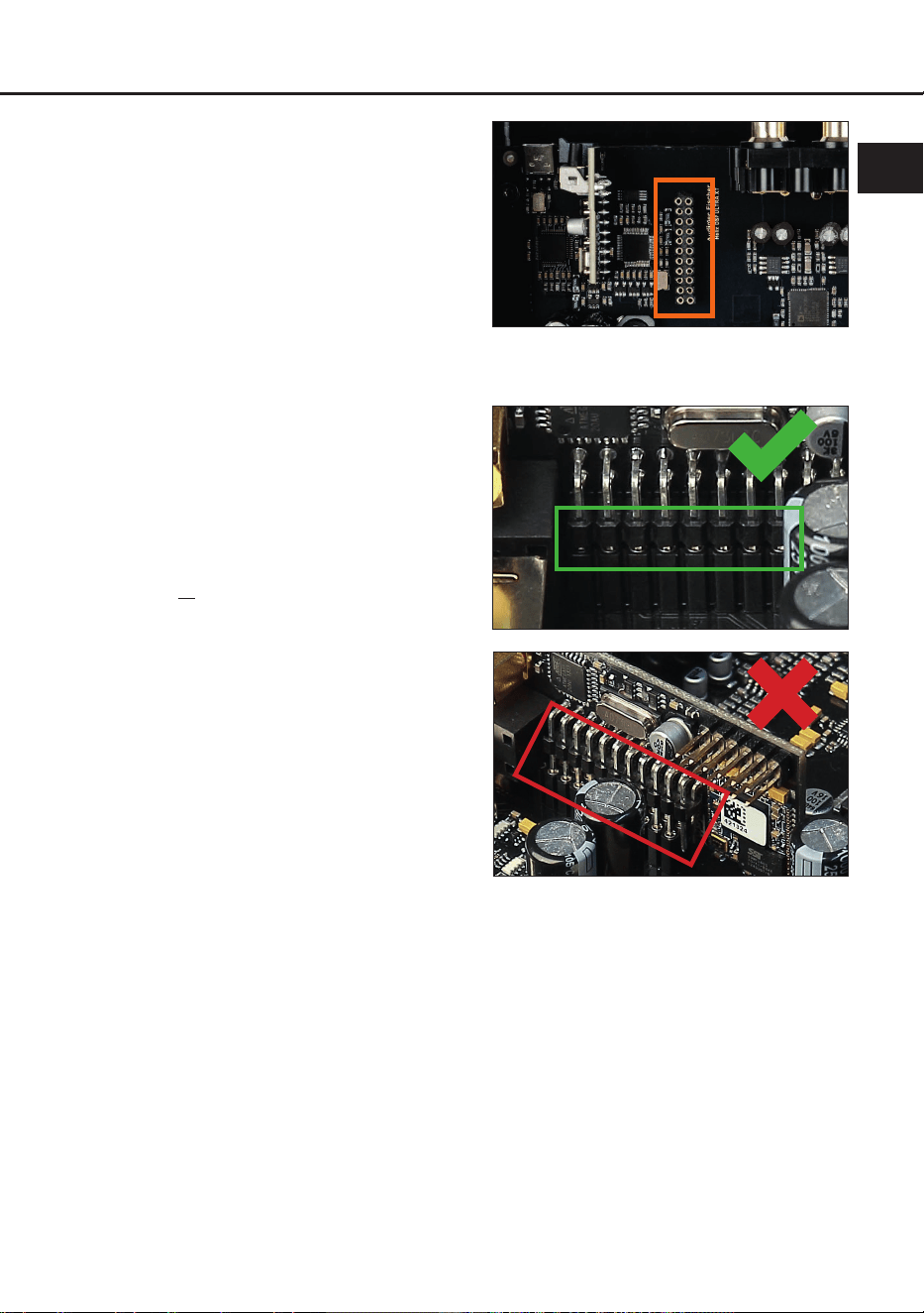
33
Installing Extension Card 2.0
en
By installing an Extension Card 2.0 (EC 2.0), the
signal processor can be upgraded with additional
interfaces – such as high-denition Bluetooth
®
au-
dio streaming, additional analog inputs, and other
features.
For installation, the device must be opened and
the cover panel of the EC 2.0 slot must be re-
placed.
Important: Only use EC 2.0 modules approved
for this device and install them exclusively in
the designated slot. Using incorrect modules
or installing them in the wrong location may
cause damage to the signal processor, the
Extension Card, the vehicle’s radio system, or
other components.
This section explains how to install and commis-
sion an Extension Card 2.0 (EC 2.0) for initial use:
1. Disconnect connections
Disconnect all cable connections from the
device.
2. Open signal processor
To open the device, rst loosen the twelve
Allen screws of the bottom plate and remove
it. Then remove the side panel with the EC 2.0
slot after loosening the six screws (two Allen
screws and four Phillips screws).
3. Prepare the side panel
Remove the cover panel of the EC 2.0 from
the previously removed side panel by loosen-
ing the two Allen screws on the back.
Now install the new cover panel supplied with
the EC 2.0. Ensure correct alignment and only
tighten the screws hand-tight.
4. Prepare EC 2.0
Prepare the module for installation according
to its instruction manual.
5. Insert EC 2.0 into the signal processor
Insert the module into the designated socket
inside the device (see marking in the following
image).
Make sure that the module is installed proper-
ly and all pins are fully inserted into the socket.
6. Reassemble the signal processor
Install the side panel with the six screws, then
install the bottom plate with the twelve screws.
7. Secure EC 2.0
Bolt the module to the side panel. Precise
mounting information can be found in the in-
struction manual of the respective EC 2.0.
8. Commissioning
Reconnect all cables and switch the device
on. The EC 2.0 is automatically detected by
the device and the module’s Info LED lights up
green.
9. Conguration in the DSP PC-Tool
The EC 2.0 can now be congured via the
DSP PC-Tool software.

34
Technical data
Inputs ..................................................................... 8 x RCA / Cinch
12 x Highlevel speaker input
1 x Optical SPDIF (24 - 96 kHz)
1 x Coaxial SPDIF (24 - 192 kHz)
1 x Extension Card 2.0
1 x USB PerfectStream (44.1 - 192 kHz)
Input sensitivity ...................................................... RCA / Cinch: 1 - 8 Volts
Highlevel: 4 - 32 Volts
Outputs .................................................................. 16 x RCA / Cinch
1 x Optical SPDIF (96 kHz)
1 x Remote Out
Output voltage ....................................................... 8 Volts
Frequency response .............................................. 10 Hz - 44,000 Hz
DSP resolution ....................................................... 64 Bit
DSP power ............................................................ 2 x 295 MHz (2.4 billion MAC operations/sec.)
Sampling rate ........................................................ 96 kHz
DSP type ............................................................... 2 x Audio signal processor
Signal converters ................................................... ADC: ESS Technology ES9841Q with HyperStream
®
IV architecture and SABRE technology
DAC: ESS Technology ES9081Q with HyperStream
®
IV architecture and SABRE HIFI
®
technology
Signal-to-noise ratio (A-weighted @ 1 kHz) .......... Digital input: 128 dB
Analog input: 116 dB
Total harmonic distortion (THD+N @ 1 kHz) ......... Digital input: <= -110 dB / 0.0003 %
Analog input: <= -108 dB / 0.0004 %
IM distortion (IMD) @ 1 kHz .................................. Digital input: <= -102 dB / 0.0008 %
Analog input: <= -102 dB / 0.0008 %
Crosstalk @ 10 kHz ............................................... > 100 dB
Operating voltage .................................................. 9.6 - 18 Volts (max. 5 sec. down to 6 Volts)
Power rating .......................................................... DC 12 V
1.2 A max.
Current draw .......................................................... 800 mA
Max. remote output current ................................... 500 mA
Operating temperature range ................................ -40 °C to +70 °C
Additional features ................................................. Extension Card 2.0 slot, GND Connection
switch, Smart Control Port, 32 Bit CoProcessor,
ADEP.3 circuit, Auto Remote switch, USB-C, USB
PerfectStream
Dimensions (H x W x D) ........................................ 55 x 255.6 x 170 mm / 2.17 x 10.06 x 6.69”
35
en
These notices do not aect the buyer’s statutory rights in case of defects against the seller. Damage
caused by improper installation, incorrect electrical connection, overload, voltage spikes in the vehicle
electrical system, improper use, modications not approved by the manufacturer or resulting from failure
to observe this user manual is not covered by any services exceeding the statutory liability for defects.
For service inquiries, please contact your dealer or our support and provide proof of purchase and a
description of the fault. To help prevent transport damage, please use the original packaging if possible
or other packaging suitable for safe transport. Subject to technical changes, misprints, and errors. Man-
datory statutory liability remains unaected.
The Bluetooth
®
word mark and logos are registered trademarks owned by Bluetooth SIG, Inc. and any
use of such marks by Audiotec Fischer GmbH is under license.
Other trademarks and trade names are those of their respective owners.
Service information
This product bears the CE marking. With it, Audiotec Fischer GmbH declares conformity
with the applicable harmonization legislation of the European Union.
This symbol means that the product must not be disposed of with unsorted household
waste. At the end of its service life, take it to a designated collection or return point for waste
electrical and electronic equipment. Proper disposal of waste equipment helps to prevent
environmental and health damage.
This product bears the UKCA marking. With it, Audiotec Fischer GmbH declares conformity
with the applicable requirements of Great Britain.
This product bears the EAC marking. With it, Audiotec Fischer GmbH declares conformity
with the applicable technical regulations of the Eurasian Economic Union (EAEU).
Trademarks
Disposal information
Regulatory notes

Audiotec Fischer GmbH
Hünegräben 26 - 28 · 57392 Schmallenberg · Germany
Tel.: +49 2972 9788 0 · Fax: +49 2972 9788 88
E-mail: helix@audiotec-scher.com · Internet: www.audiotec-scher.com
Made in Germany