SPECIFICATIONS
CATEGORY OF CABLE
• Shielded/unshielded communication cable with RJ-11 and RJ-45
connectors.
• Ethernet 10 Base-T, Token Ring, EIA/TIA-568A/B, AT&T 258A, and
USOC.
Maximum testing length for all cable types is 300m / 1,000 feet.
MULTIPLE FUNCTIONS
• Testing cables before or after their installation.
• Mapping Function (to test individual wire pairs or coaxial cables).
• Cable identification (straight or cross-pinning).
• Pair identification (straight or cross-pinning).
• Open/short wiring test.
• Shield opens
• Automatic two speeds
ENVIRONMENTAL CONDITIONS
• Operating Conditions: 0
O
C - 45
O
C / 32
O
F - 113
O
F
70% RH max.
• Storage Conditions: –10
O
C - 50
O
C / 14
O
F - 122
O
F
80% RH max.
POWER
• Standard or alkaline 9V battery NB. Not supplied
INTRODUCTION
The Network Cable Tester is a convenient instrument for testing different
shielded/unshielded wiring schemed communication cable with RJ-11
and RJ-45 connectors. This tester can be used for testing cables before
and/or after they are installed. Testing status is indicated by multiple
LEDs.
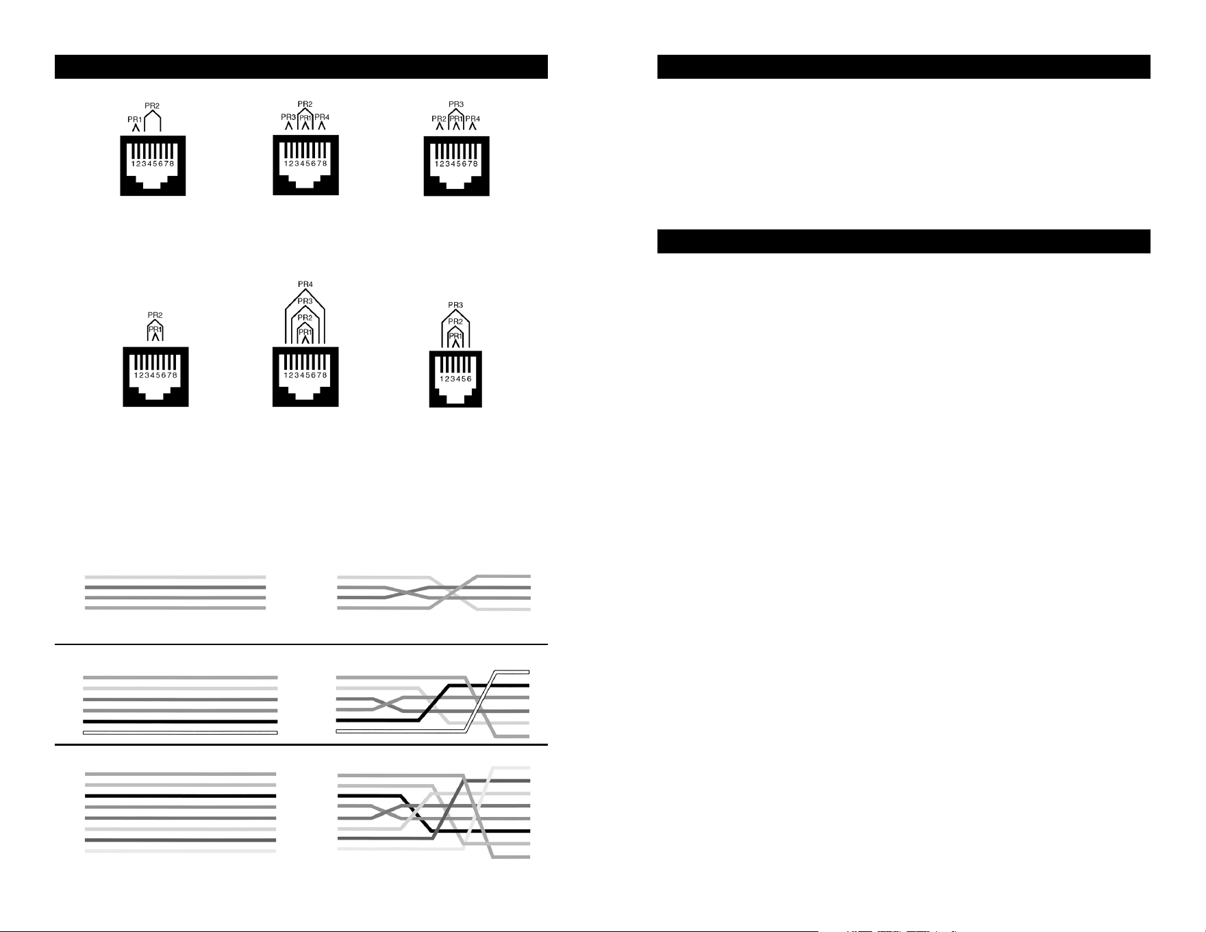
Ethernet
10Base-T
EIA/TIA-568A EIA/TIA-568B
AT&T 258A
8-Position
Token Ring
USOC 8 USOC 4
(Prs. 1&2)
USOC 6
(Prs. 1,2 & 3)
WIRING SCHEMES
(Y) 1
(G) 2
(R) 3
(BL) 4
(Y) 1
(G) 2
(R) 3
(BL) 4
1
2
3
4
1
2
3
4
(BL) 1
(Y) 2
(G) 3
(R) 4
(BK) 5
(W) 6
1
2
3
4
5
6
(BL) 1
(Y) 2
(G) 3
(R) 4
(BK) 5
(W) 6
1
2
3
4
5
6
(BL) 1
(OR)2
(BK) 3
(R) 4
(G) 5
(Y) 6
(BN) 7
(S) 8
1
2
3
4
5
6
7
8
(BL) 1
(OR)2
(BK) 3
(R) 4
(G) 5
(Y) 6
(BN) 7
(S) 8
1
2
3
4
5
6
7
8
RJ-11 (4-Wire) Straight-Pinning RJ-11 (4-Wire) Cross-Pinning
RJ-11 (6-Wire) Straight-Pinning RJ-11 (6-Wire) Cross-Pinning
RJ-45 (8-Wire) Straight-Pinning RJ-45 (8-Wire) Cross-Pinning
NOTE: Cross-pinning is for typical telephone use.
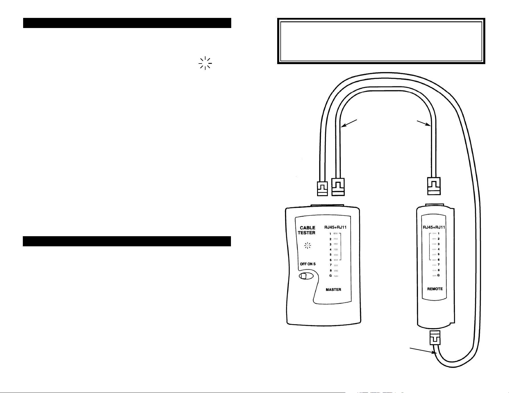
Operation:
1. Slide the power switch to on, the power light will flash (“S” for slow
speed test).
2. To test a communication cable, connect an end of the cable to the
Master tester and the other end of the cable to the Remote tester.
3. The LED’s will light in sequence 1 - G (G is GND/Shield) on the
tester. Check that the correct corresponding LED lights on the
remote unit per your wiring configuration.
- A short is indicated by no LEDs lighting on the remote.
- An open wire/shield by no LEDs lighting on the tester and remote.
- LEDs lighting up in a wrong order eg. Pin 1, Pin 2, Pin 4, Pin 3, Pin 5,
Pin 6, Pin 7, Pin 8, indicates a crossed connection at Pins 3 and 4.
Configuration
for Testing RJ45
Communication
Cable
Configuration
for Testing RJ11
Communication
Cable
CAUTION
DO NOT test cables connected to electric power or active devices. To
avoid electric shock, disconnect the power to the cable under test.
Connection to an active power cable can result in injury or even death.
GENERAL MAINTENANCE
To clean, wipe the case with a damp cloth and detergent (do not use
abrasives or solvents).
When the power LED does not light when the unit is switched on, you need to replace
the battery. The terminator does not use a battery.
BATTERY REPLACEMENT
The tester is powered by a single standard or alkaline 9V battery. Use the
following procedure to replace the battery.
1. Disconnect the cables from the tester.
2. Open the battery cover, carefully remove the old battery, and replace
with a new battery.
3. Reinsert the battery into the case, dressing the battery leads so that
they will not be pinched between the case and the battery cover.
4. Reinstall the battery cover.
MAINTENANCE
OPERATION INSTRUCTIONS
Warning:
1. Caution: Do not connect the cable tester to live circuits or devices
as it may be damaged by over voltage.
2. Turn on the Master Cable Tester Box. If the power light ( O ) does
not light, replace the 9V battery NB. Not supplied.
3. When testing communication cable with RJ11 connectors, use only
the RJ11 jacks on the tester and remote.