DOCUMENTATION
MAINTENANCE MANUAL
Ed: 10/2025
3-E490099EM / F49615


CHEF’SCOMBI
Page 3 / 76
3VE490099EM – 10/25
Table of contents
1. THE ESSENTIALS ....................................................................................................................................................... 5
1.1 REPLACING ELECTRONIC BOARDS .................................................................................................................................. 5
1.2 REPLACING THE HUMIDITY SENSOR................................................................................................................................ 6
1.3 REPLACING THE FOOD CORE TEMPERATURE PROBE .................................................................................................. 7
1.4 REPLACING THE TEMPERATURE PROBE OF ELECTRIC STEAM GENERATOR ........................................................... 7
1.5 REPLACING THE TEMPERATURE PROBE OF GAS STEAM GENERATOR ..................................................................... 8
1.6 REPLACING THE AMBIANT TEMPERATURE PROBE ........................................................................................................ 8
2. SPECIFIC TOOLS ........................................................................................................................................................ 9
3. SETTINGS .................................................................................................................................................................. 10
3.1 PIN CODES ......................................................................................................................................................................... 10
3.2 SOFTWARE INITIALIZATION ............................................................................................................................................. 10
3.3 SETTING THE SOFTWARE LANGUAGE ........................................................................................................................... 10
3.4 WATER TREATMENT CAPACITY ...................................................................................................................................... 11
3.5 CHECKING SOFTWARE VERSION.................................................................................................................................... 11
3.6 UPDATING THE SOFTWARE ............................................................................................................................................. 11
3.7 PROBES CALIBRATION ..................................................................................................................................................... 13
3.8 PARAMETERS SCREEN .................................................................................................................................................... 14
4. PREVENTIVE MAINTENANCE.................................................................................................................................. 16
4.1 LIST OF ACTIONS .............................................................................................................................................................. 16
4.2 SETTING MAINTENANCE INTERVENTION FREQUENCY, DAILY USAGE RATE ........................................................... 18
5. TROUBLESHOOTING ............................................................................................................................................... 20
5.1 TROUBLESHOOTING METHOD ........................................................................................................................................ 20
5.2 ERRORS MESSAGES ........................................................................................................................................................ 20
5.3 MAINTENANCE SCREENS ................................................................................................................................................ 29
5.4 COMMUNICATIONS LEDS ................................................................................................................................................. 32
5.5 OTHER SYMPTOMS ........................................................................................................................................................... 36
5.6 FLOWCHART ...................................................................................................................................................................... 38
5.7 RESET ................................................................................................................................................................................. 42
6. ELECTRIC DIAGRAMS ............................................................................................................................................. 44
6.1 DIAGRAMS .......................................................................................................................................................................... 44
6.2 6 AND 10 LEVEL CAVITY VENTILATION ........................................................................................................................... 50
6.3 GREASE COLLECTION OPTION ....................................................................................................................................... 51
6.4 PARTS LIST ........................................................................................................................................................................ 52
7. HYDRAULIC DIAGRAM ............................................................................................................................................. 54
7.1 6 AND 10 LEVEL OVENS .................................................................................................................................................... 54
8. GAS DIAGRAM .......................................................................................................................................................... 56
8.1 6 AND 10 LEVEL OVENS .................................................................................................................................................... 56
9. ACCESS TO COMPONENTS .................................................................................................................................... 57
9.1 LOCATION OF TECHNICAL COMPONENTS ..................................................................................................................... 57
9.2 ACCESS TO COMPONENTS ............................................................................................................................................. 57
10. COMPONENTS ...................................................................................................................................................... 60
10.1 ELECTRONIC BOARDS ...................................................................................................................................................... 60
10.2 ELECTRIC BOARDS ........................................................................................................................................................... 64
10.3 OTHER COMPONENTS ...................................................................................................................................................... 65
11. RECOMMENDED AND EMERGENCY SPARE PARTS ....................................................................................... 67
12. COMBUSTION GAS ANALYSIS PROCEDURE ................................................................................................... 69
13. CONTROL OF THE ELECTRODES (GAS BURNER)........................................................................................... 71
14. CHANGING THE EQUIPMENT FROM ONE GAS TO ANOTHER ....................................................................... 72
14.1 GAS FLOW RATES AND POWERS.................................................................................................................................... 72

CHEF’SCOMBI
Page 4 / 76
3VE490099EM – 10/25
14.2 CHART OF GAS INJECTORS ............................................................................................................................................. 72
14.3 CHANGEOVER FROM ONE GAS TO ANOTHER: ............................................................................................................. 72
14.4 CHANGING/ADJUSTING GAS VALVE ............................................................................................................................... 74
15. CONVERSION TABLES ........................................................................................................................................ 75
15.1 PT100 PROBE ..................................................................................................................................................................... 75
15.2 CELSIUS / FAHRENHEIT TEMPERATURE ........................................................................................................................ 76
15.3 WATER HARDNESS ........................................................................................................................................................... 76
15.4 PRESSURE ......................................................................................................................................................................... 76
1 - THE ESSENTIALS
CHEF’SCOMBI
Page 5 / 76
3VE490099EM – 10/25
1. THE ESSENTIALS
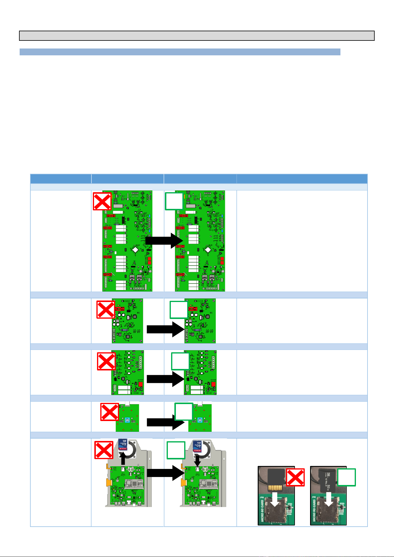
1.1 REPLACING ELECTRONIC BOARDS
When replacing the electronic boards (Aag gas board, Ahu humidity board, Ar Main board or Ac encoder board), no additional updates or settings are
required. Simply follow these steps:
» Remove the faulty board.
» Install new board in its place.
» Make necessary connections.
On start-up, the system will automatically set up the new board
However, to replace the Ai interface board, it is essential to recover the SD card from the faulty board. This makes it easier to set parameters and
recover customer settings and data. Follow these steps:
» Remove faulty interface board.
» Remove SD card from the interface board.
» Insert this SD card into interface board.
» Install new interface board.
» Make necessary connections.
When it starts up, the system will ask you to confirm that the parameters have been copied and will
automatically configure the board.
Boards
Faulty board
New board
Application
Main board - Ar
No settings - Automatic recognition between boards
Humidity board - Ahu
No settings - Automatic recognition between boards
Gas board - Aag
No settings - Automatic recognition between boards
Encoder board - Ac
No settings - Automatic recognition between boards
Interface board - Ai
Recover the SD card and insert it on the new
Interface board.
Copy settings and customer data if the SD card
present on the faulty board is recovered.
✓
✓
✓
✓
✓
✓
1 - THE ESSENTIALS
CHEF’SCOMBI
Page 6 / 76
3VE490099EM – 10/25
1.1.1 INTERFACE BOARD SETTING
This step is crucial if the interface board on your Chef'sCombi oven is to be replaced. There are two methods available for carrying out this operation:
you can either copy the existing configuration using the SD card from the faulty interface board, or you can configure the oven manually. Be sure to
follow the instructions carefully to ensure correct configuration.
It is in your interest to recover the SD card, as all customer data, history, logs, settings and oven
configuration will be preserved.
SD card: Mini 4GB / FAT32 formatted
Replace the SD card on the faulty interface board.
» When replacing interface board, make sure you recover the SD card present on it.
» Insert this SD card into the new interface board.
» Start oven.
Important, When the oven starts up, the system will detect that there is no configuration and will offer to copy the
configuration.
» If you accept to copy the configuration, the oven will be configured with the previously saved settings.
» If you refuse, or if the SD card is corrupted, you will have to configure the oven manually by following the instructions
(►Troubleshooting - Reset).
Insert a blank SD card into the Interface board
» If you do not have the original SD card or if it is damaged, you can use the blank SD card present on the new Interface
(check that it is present).
» Start oven.
When it starts up, the system will detect that there is no configuration and will ask you to configure the oven.
» Configure the oven manually by following the instructions (►Troubleshooting - Reset).
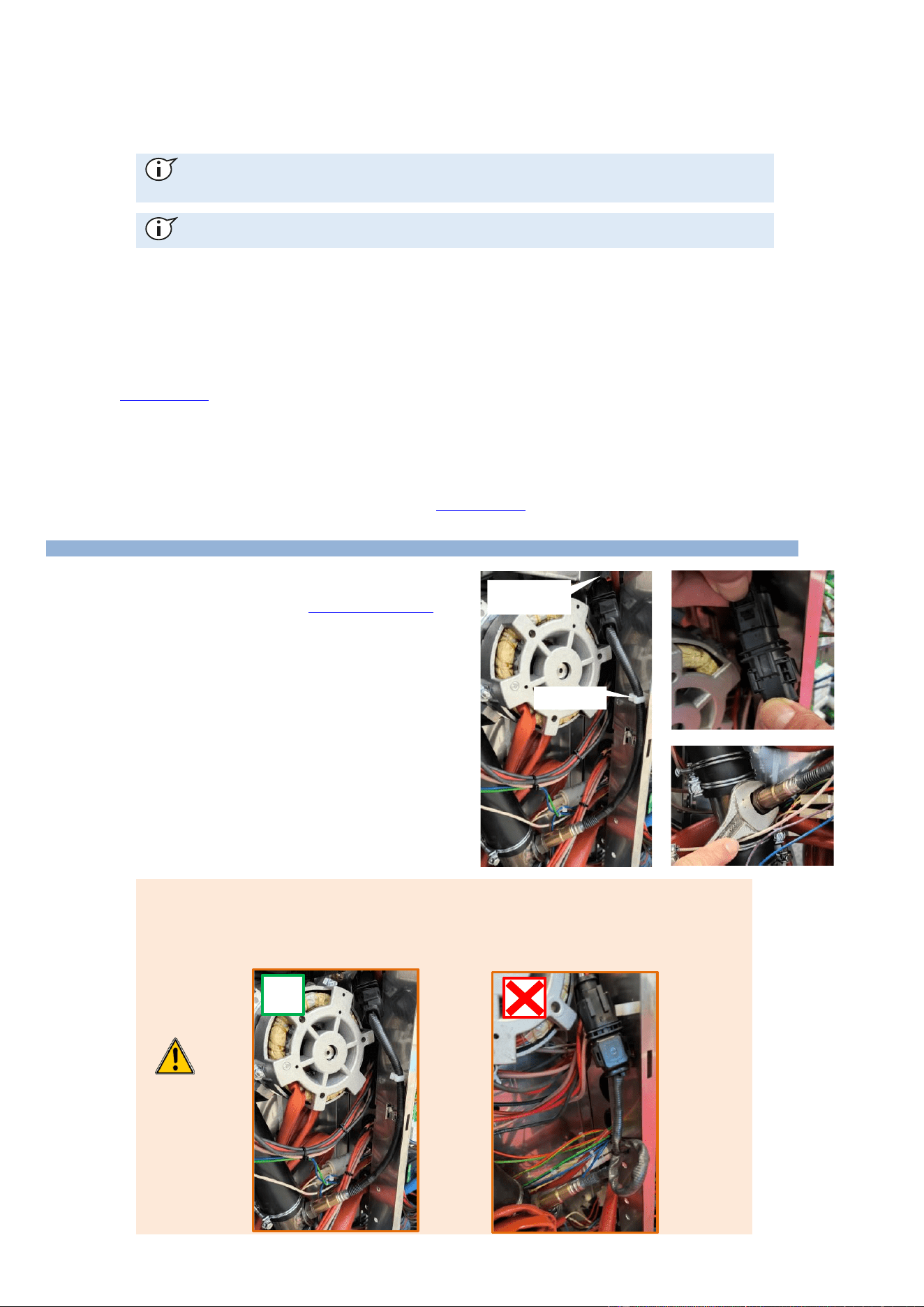
1.2 REPLACING THE HUMIDITY SENSOR
Prepare your intervention:
✓ Remove the left-hand oven cover (►Access to components)
✓ Tools: 22" spanner
Disconnecting the probe
» Disconnect the probe at the Black terminal block by pressing on
the terminal block tab
Removing the probe
» Unscrew the probe using the spanner
» Remove the probe
Fitting the new probe
» Reposition and screw the probe fully into its housing, taking care
not to twist or damage the cable
» Connect the probe to the black terminal block, taking care to
follow the instructions below.
When connecting the new probe to the humidity board, make sure that :
» The cable is as straight as possible (no loops)
» The cable is not twisted
» The cable has passed through the cable clip provided.
» The cable is routed through the highest grommet on the board to avoid twisting the cable
✓
Cable clip
Sheet metal
pass-through
1 - THE ESSENTIALS
CHEF’SCOMBI
Page 7 / 76
3VE490099EM – 10/25
1.3 REPLACING THE FOOD CORE TEMPERATURE PROBE
Prepare your intervention:
✓ Remove the right-hand ladder from the cooking chamber
(►Access to components)
✓ Tools: Wrenches, screwdriver
Disconnecting the probe
» Unscrew the 2 fixing screws (8 wrench) from the core probe
pass-through and remove the 2 screws.
» Gently pull on the lead wire to access and release the
connector.
» Disconnect the 2 wires from the connector.
» Remove the probe and its gasket.
Mounting the new probe
» Connect the probe to the connector and insert the connector
into its housing.
» Position the gasket and attach the probe pass-through to the
cooking cavity.
Check / Test
» Perform the probe calibration procedure.
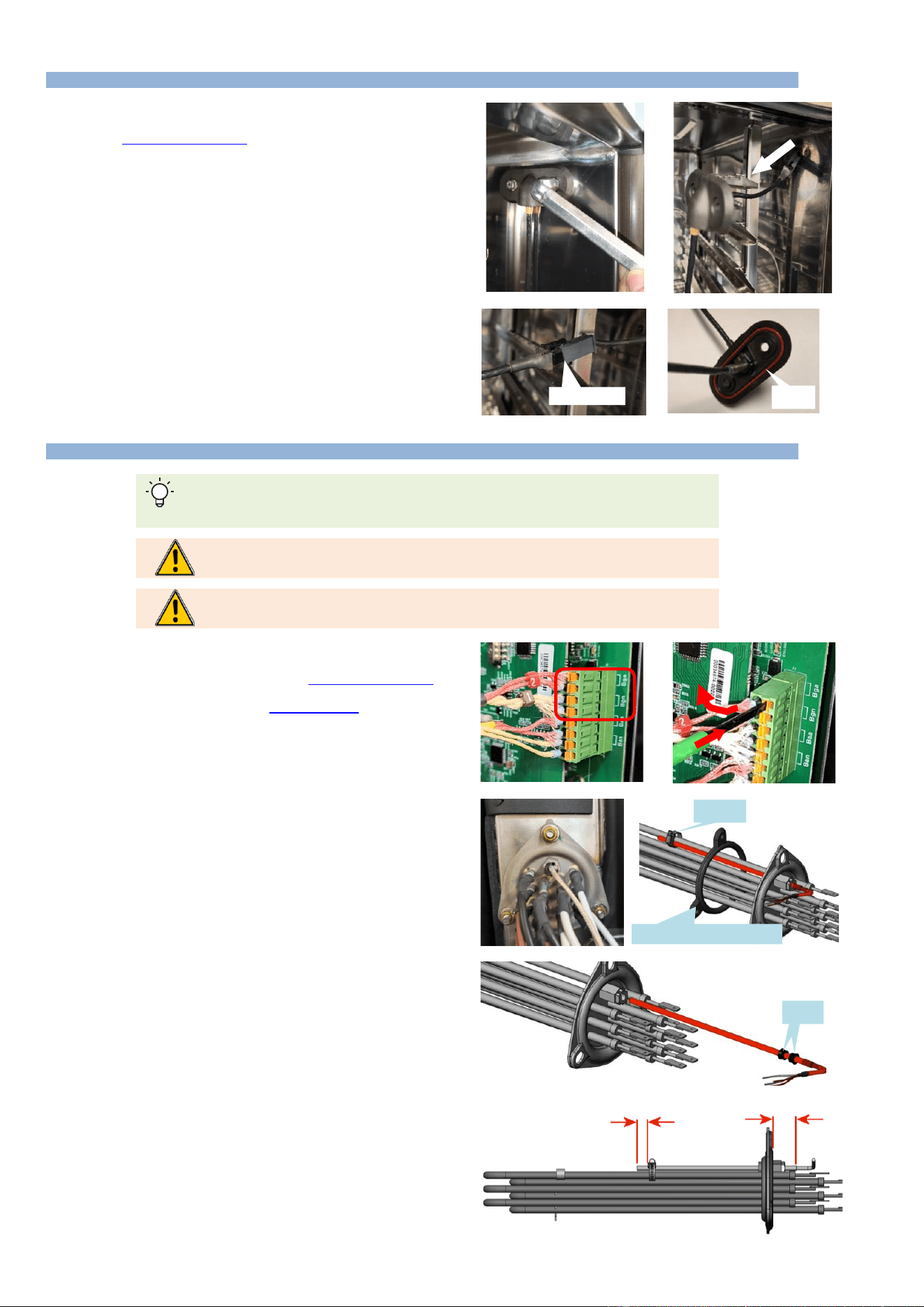
1.4 REPLACING THE TEMPERATURE PROBE OF ELECTRIC STEAM GENERATOR
Locate the probe wires on the terminal block according to color. Red wire: analog, White wire:
numeric.
It is imperative to systematically change the probe seals each time the probe is serviced
(replacement or inspection).
It is imperative to systematically change the immersion element seal when servicing the
immersion element.
Prepare your intervention:
✓ Remove the left-hand oven panel (►Access to components -
Left-hand side panel)
✓ Drain the steam generator (►Troubleshooting - Maintenance
screens - Hydraulics diagram)
✓ Tools: Wrenches, screwdriver
Probe disconnection
» Disconnect the wires from the terminal block on the Main board.
Removing the immersion element
» Unscrew the 3 flange nuts on the immersion heater fitted with
the temperature probe.
» Remove the immersion element.
Removing the probe
» Unscrew and remove the clamp holding the probe to the
immersion element.
» Unscrew the probe and remove it.
Mounting the new probe
» Position the new probe on the immersion element according to
the instructions.
• Insert the cable gland and the two seals on the
temperature probe.
• Insert the temperature probe into the immersion element
housing, leaving it protruding by 0.4 inch, then tighten
the cable gland.
• Secure the probe to the top bar with a metal Serflex
clamp at 0.2 inch from the end of the probe.
Mounting the immersion element
» Insert the immersion element into the steam generator not
forgetting to change the gasket.
Check / Test
» Perform the probe calibration procedure.
Connector
gasket
Joints
Seals
0.2"
0.4"
Seal immersion element
Collar
1 - THE ESSENTIALS
CHEF’SCOMBI
Page 8 / 76
3VE490099EM – 10/25
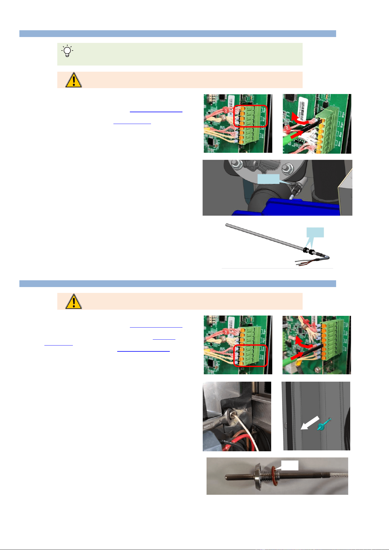
1.5 REPLACING THE TEMPERATURE PROBE OF GAS STEAM GENERATOR
Locate the probe wires on the terminal block according to color. Red wire: analog, White wire:
numeric.
It is imperative to systematically change the probe seals each time the probe is serviced
(replacement or inspection).
Prepare your intervention:
✓ Remove the left-hand oven panel (►Access to components -
Left-hand side panel)
✓ Drain the steam generator (►Troubleshooting - Maintenance
screens - Hydraulics diagram)
✓ Tools: Wrenches, screwdriver
Probe disconnection
» Disconnect the wires from the terminal block on the Main board.
Removing the probe
» Unscrew the collar holding the probe to the gas steam generator.
» Remove the probe and the two seals and replace them.
Mounting the new probe
» Position the new probe in the steam generator according to the
instructions
• Insert the 2 seals on the temperature probe as far as
they will go.
• Insert the probe into the steam generator and tighten
with a screw clamp.
Check / Test
» Perform the probe calibration procedure.
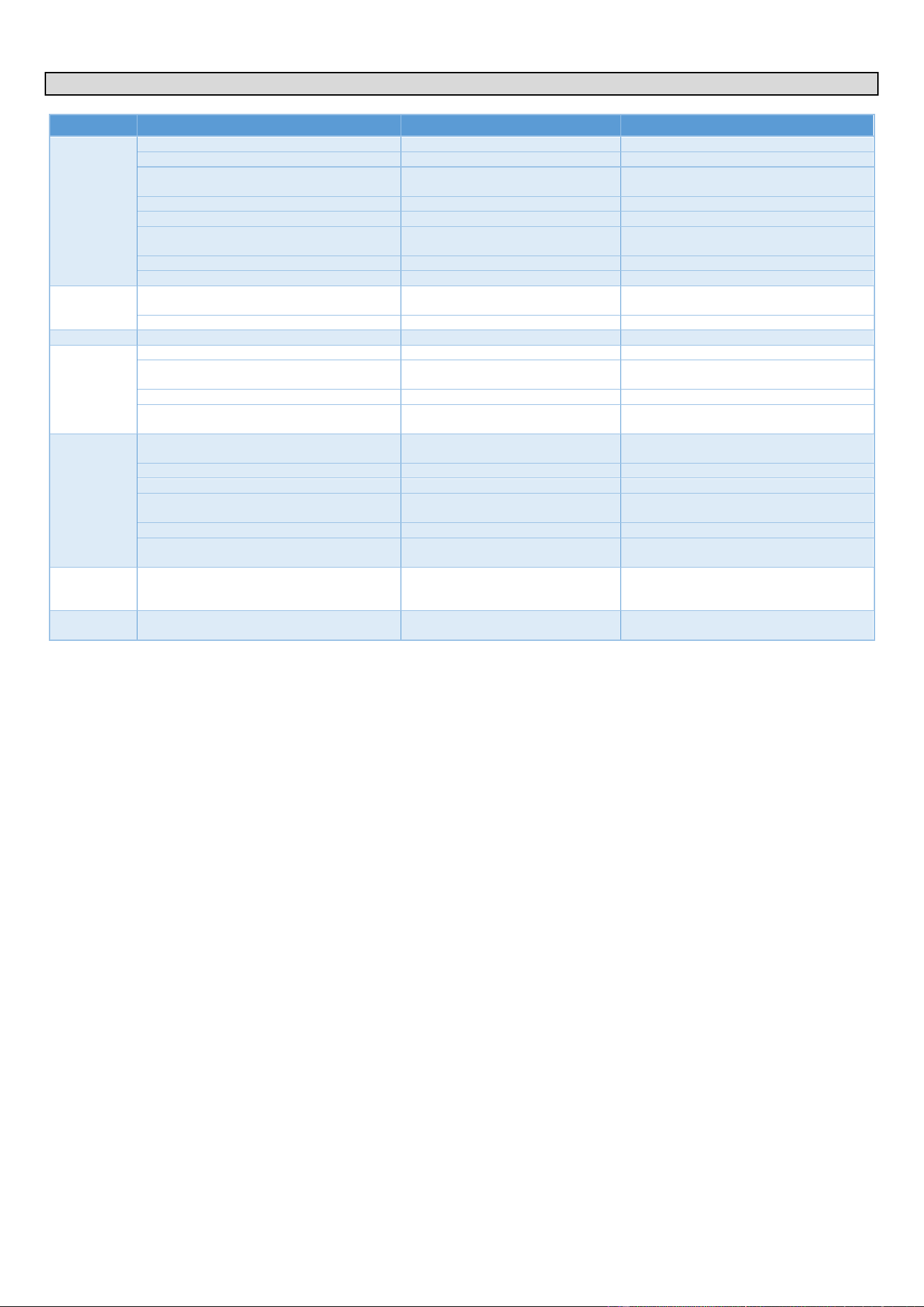
1.6 REPLACING THE AMBIANT TEMPERATURE PROBE
It is imperative to systematically change the probe seal each time the probe is serviced
(replacement or inspection).
Prepare your intervention:
✓ Remove the left-hand oven panel (►Access to components -
Left-hand side panel)
✓ Remove the left-hand runner from the oven (►Access to
components - Runners)
✓ Remove the ventilation duct (►Access to components -
Ventilation duct)
✓ Tools: Wrenches, screwdriver
Probe disconnection
» Disconnect the wires from the terminal block on the Main board.
Removing the probe
» In the technical compartment, unscrew the threaded hexagonal
spacer (14 mm spanner) used to secure the probe.
» Remove the probe and its seal from the inside of the oven.
Mounting the new probe
» Lubricate and assemble the O-ring with the ambient probe
» Pass the wires of the new probe through form the inside of the
oven.
» Position and secure the new probe.
» Insert and press the probe against the inside of the cooking
cavity and secure it with the threaded hexagonal spacer.
» Reconnect the probe wires to the terminal block on the Main
board
Check / Test
» Perform the probe calibration procedure.
Collar
Joints
seals
Seal
2 - SPECIFIC TOOLS
CHEF’SCOMBI
Page 9 / 76
3VE490099EM – 10/25
2. SPECIFIC TOOLS
Chapter
Tools
Characteristics
Application
Common
Standard hand tool kit
Cutting tools
Retractable blade knife
Set of metric wrenches (flat, pipe, ratchet
with sockets, Allen Hex Key)
From 5.5 to 22 mm
Set of screwdrivers (flat, Phillips)
Philips.
Pliers (multi-socket, flat, cutting, stripping)
Measuring tools (tape measure, calliper,
level)
Classic tubular level 40cm
Wrench
PPE
Standard
Personal protection for technicians.
Water
Water control kit
Allows control of Hardness, Cl-, PH,
Conductivity and Cl2
Check the characteristics of the water.
Water pressure gauge
Measuring range 0-10 bar
Check water supply pressure.
Drain
Container
3 litres minimum
Fill the drain box.
Electric
Verification of absence of voltage (VAT)
Max 690V a.c.
Check that there is no voltage.
Multimeter-Voltmeter
Max 690V a.c.
Various checks on electrical and electronic
components.
Draw knife
Typ : "JOKARI" No 50 and No 28
Pull out the power cable.
Torque spanner
Type: J208-50 + 13mm 3/8" square
socket
Motor mounting: Torque 14N/m.
Gas
Flue gas analyser
Type: "Testo 300 professionnel or
equivalent
Check the level of CO emitted when the
oven is operating.
Water column or electronic pressure gauge
Type:Testo 510 or equivalent
Check the gas pressure.
Spray or Electronic Gas Leak Detector
Type: 1000 Bubbles spray
Check gas connection for leaks.
Thickness gauges
Dimensions: 6mm and 3.5mm
Position the ignition and detection
electrodes.
Ratchet spanner
Size 8mm M5 screw
Remove the gas exchanger.
Claw key
Opening 1/2-3/4
Dismantle the gas hoses and connections if
the grease collection option is chosen.
Software
USB flash drive
USB2 type: Maximum capacity = 32
GB - FAT32 formatted
Updating software version, copying oven
configuration data and customer data
(protocols, images, etc.).
Mechanical
Hub puller
Type: "Facom U35.L or similar pulling
tool.
Remove the convection fan to service the
motor.
3 - SETTINGS
CHEF’SCOMBI
Page 10 / 76
3VE490099EM – 10/25
3. SETTINGS
3.1 PIN CODES
The access PIN codes are essential for entering the settings menu reserved for the installer, user (after setting by the Chef) and maintenance. They
ensure the security and protection of the sensitive settings of your Chef'sCombi oven. Please keep these codes in a safe place and only share them
with authorised personnel.
Code No
Description
Level
Remark
0000
Default user code
1
Accessible in the settings / Can be changed by
the user.
CHEF
Emergency code for Chef
1
If the password set by the Chef (user) is forgotten
(after changing 0000).
INST
Installers
5
Access to installer parameters
SERV
Network Service Technicians
7
Access to 1st level maintenance parameters
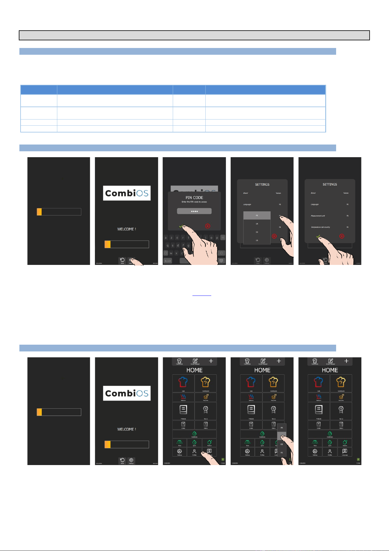
3.2 SOFTWARE INITIALIZATION
» Switch on the display by holding down the encoder button.
» Before the power-on bar graph is displayed, press the « Settings » button.
The PIN code identification pop-up appears.
» Enter PIN code (level 5 or 7) to access “Installer” parameters (►Settings - Codes PIN).
» Confirm by pressing the « ✓ » icon. If the code is correct, access to the screen is authorized; otherwise, return to
entering the PIN code
» Press on the parameter values to modify if necessary.
The selection drop-down menu appears.
- Select the desired value.
» Confirm by pressing the « ✓ » icon.
3.3 SETTING THE SOFTWARE LANGUAGE
» Switch on the display by holding down the encoder button until the power-on bar graph is displayed.
» Wait for the "Home" menu to appear.
» Press the "Languages" button.
The language selection drop-down menu appears.
» Select the desired language (En: by example).
3 - SETTINGS
CHEF’SCOMBI
Page 11 / 76
3VE490099EM – 10/25
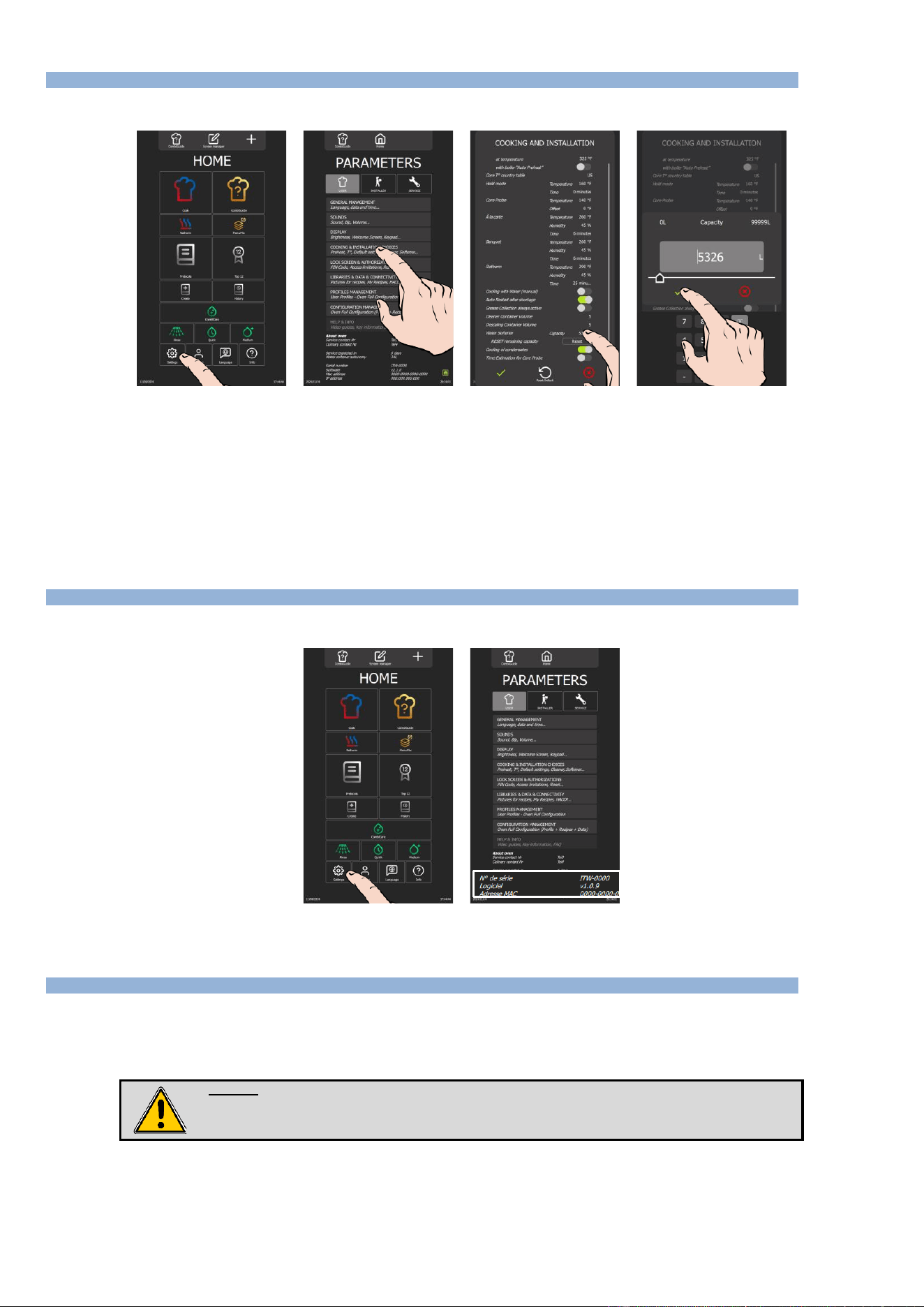
3.4 WATER TREATMENT CAPACITY
This counter is only applicable when the oven is supplied by two separate water networks.
» From the "Home" menu screen, select the "Settings" button.
The screen displays the "Parameters" menu with the "User" tab selected.
» Select "Cooking and Installation choices" button.
The screen displays the "Cooking and Installation" settings.
» Enter the capacity of the water treatment system in litres. Adjustable from 0 to 99999L. The value defaults to 0 if
there is no dedicated water treatment for the oven.
- Select the area of the value to be modified.
- Set the value using the encoder knob or the keypad.
» Confirm by pressing "✓ " icon.
» Reset the counter if necessary, by pressing the "Reset" button.
» Confirm by pressing "✓ " icon.
3.5 CHECKING SOFTWARE VERSION
The software version is visible in the "User" tab of the "Settings" screen, below the device serial number.
» From the "Home" menu screen, select the "Parameters" button.
The screen displays the "Parameters" menu with the "User" tab selected.
3.6 UPDATING THE SOFTWARE
A regular software update ensures that the oven interface has the latest developments and improvements for use by the customer and/or the
technician. The technician is alerted as soon as a new update is available via the “Vulcanequipment.com/resource-center” website software and/or the
"software info" distribution.
Before starting the update, check that the software is in the local language and change if necessary.
Warning:
Do not disconnect the power supply to the device while the software is being loaded.
Do not remove the UBS key while the software is being loaded.
The oven will be unavailable for the duration of this operation.
USB key
For this configuration operation, you will need a blank FastPad USB key or a blank USB key with the following specifications:
- Maximum capacity = 32 Gb
- Formatted in FAT32 (default allocation unit size = 4096 bytes) or formatted in FAT (default allocation unit size = 32 Kilobytes).
3 - SETTINGS
CHEF’SCOMBI
Page 12 / 76
3VE490099EM – 10/25
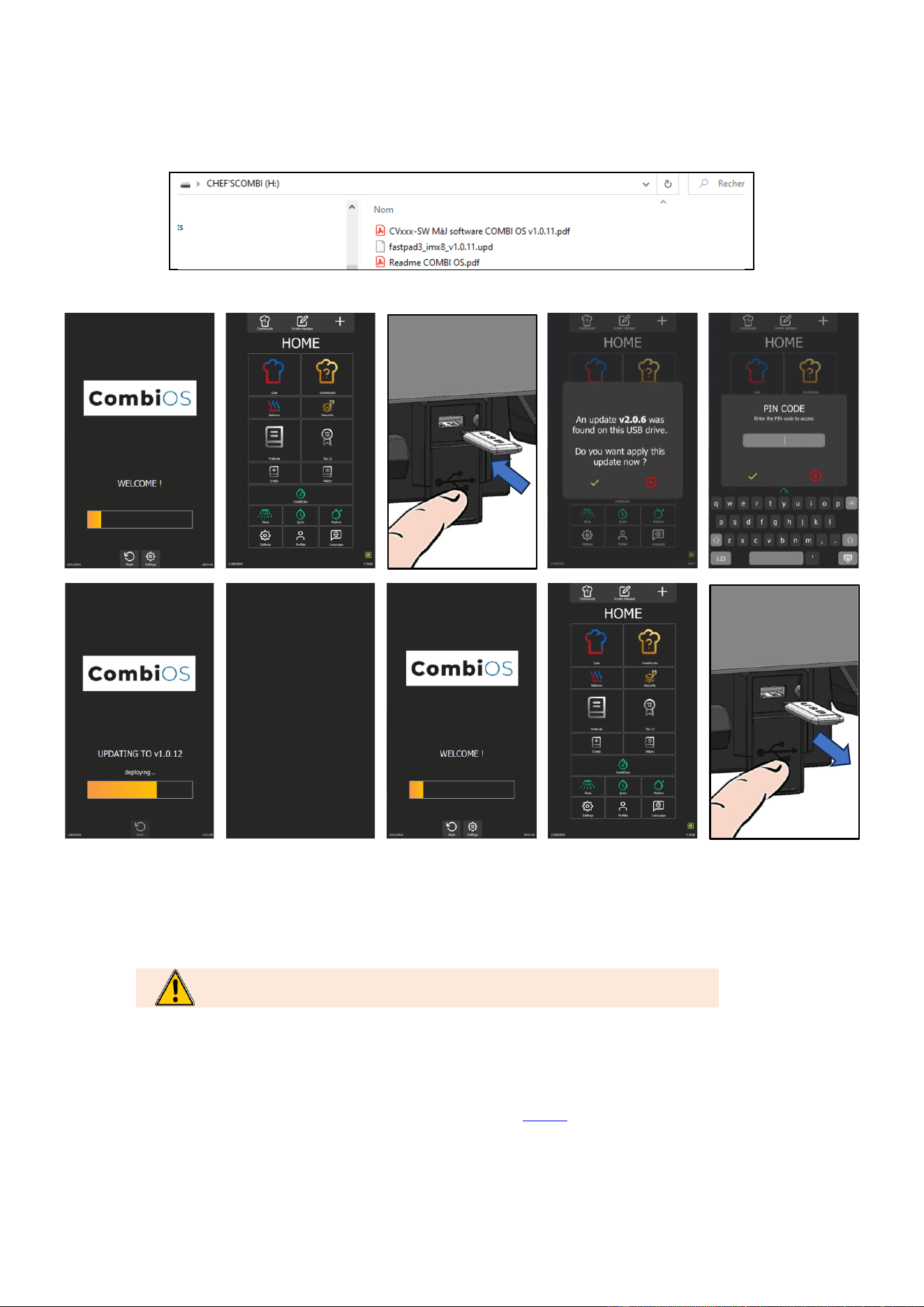
Software update file
Download the software update file "CVxxx-SW.zip" from our Vulcan website maintenance site.
Unzip the downloaded file.
Copy the executable file to the blank USB key and run it: fastpad3_imxX_VX.X.XX.upd
The files will be automatically created on the USB key. The USB key must contain only :
Procedure
Step 1
Switch on the device.
Wait for welcome menu to appear. If necessary, skip the pre-heating.
Step 2
Insert USB key with the new version of Software into the USB socket (next to the spray
hose location).
The USB socket has a protective cover.
Lift the cover upwards to insert the USB key.
Caution !
Verify flap has closed as soon as USB socket is no longer in use.
Step 3
When the USB key is connected, the "UPDATE" request window will appear.
If no window appears, this means software version is identical between the USB
key and the device.
Step 4
Confirm the update by pressing the « ✓ » icon.
Step 5
Confirm the update by entering your PIN code (level 5 or 7) (►Settings - PIN Codes).
Software will start loading.
The device may restart once during the update.
Step 5
Do not remove the USB key until the welcome screen appears.
3 - SETTINGS
CHEF’SCOMBI
Page 13 / 76
3VE490099EM – 10/25
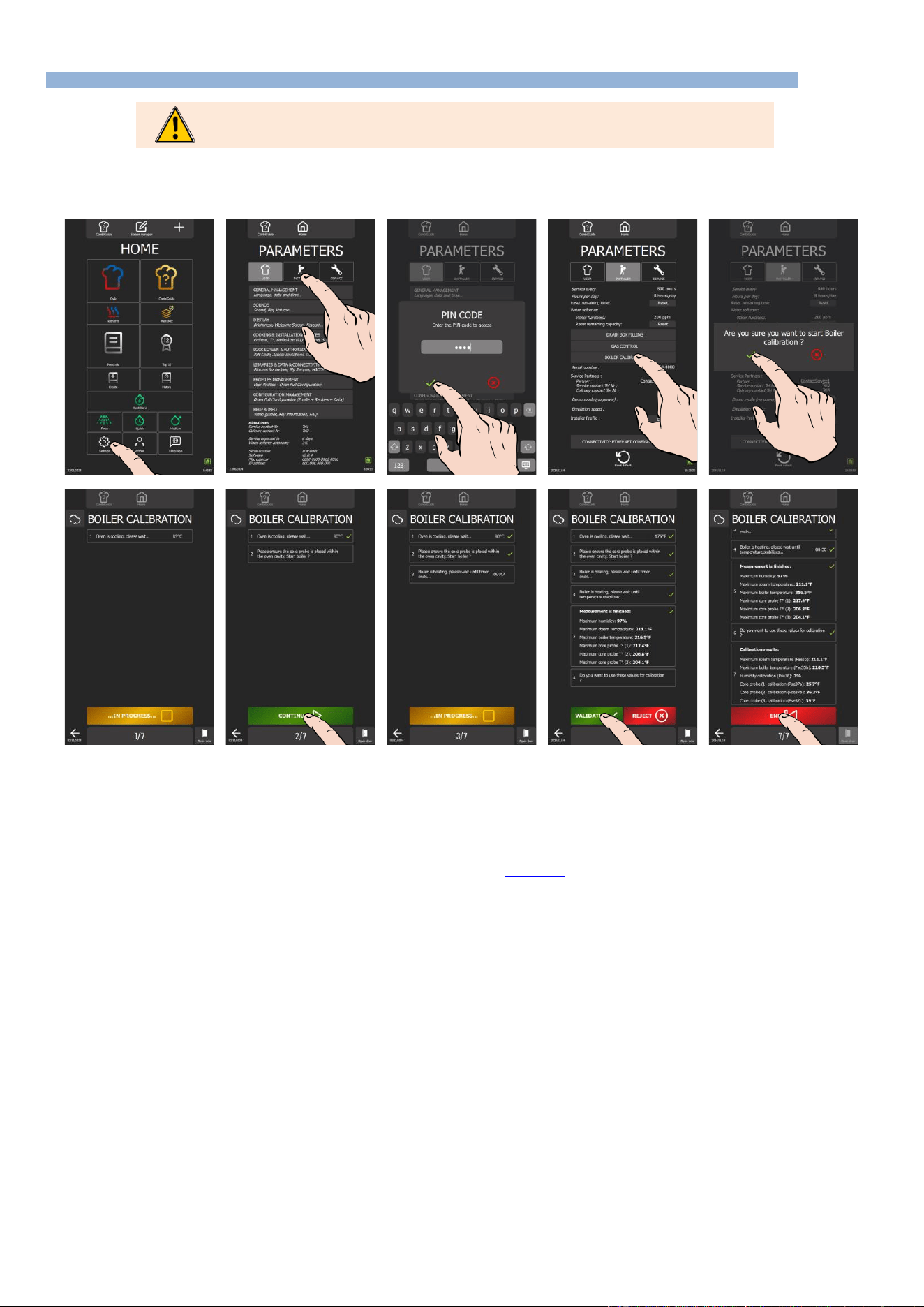
3.7 PROBES CALIBRATION
Calibration of the probes (core probe, steam generator probe and cavity probe) must be carried out
systematically each time these components are replaced.
The cavity probe, core probe and humidity sensor are calibrated during the ‘Steam generator calibration’ procedure, which takes approximately 12
minutes. If a measured value is inconsistent during the process, interrupt the check immediately by pressing the ‘Reject’ button. Then switch off the
oven and check the probe(s) concerned. Replace faulty components if necessary.
Prepare for your test:
✓ The oven door is closed.
✓ The left-hand trim panel is in place.
» From the "Home" menu screen, select the "Settings" button.
The screen displays the "Parameters" menu with the "User" tab selected.
» Select the "Installer" tab.
The PIN code identification pop-up appears.
» Enter the PIN code (level 5 ou 7) to access the "Installer" parameters. (►PIN Codes).
» Confirm by pressing the "✓ " icon. If the code is correct, access to the screen is authorised; if not, return to
entering the PIN code.
» Press the "Steam generator calibration" button
» Confirm by pressing the "✓ " icon.
The " Steam generator calibration" screen appears.
» Start the test by pressing the "Start" button.
» Follow the actions shown on the oven display "step by step".
» When point 6 "Do you want to use these values for calibration?" is displayed, press "✓ " to confirm.
» When the calibration result is displayed, press the "End" icon to return to the previous screen.
3 - SETTINGS
CHEF’SCOMBI
Page 14 / 76
3VE490099EM – 10/25
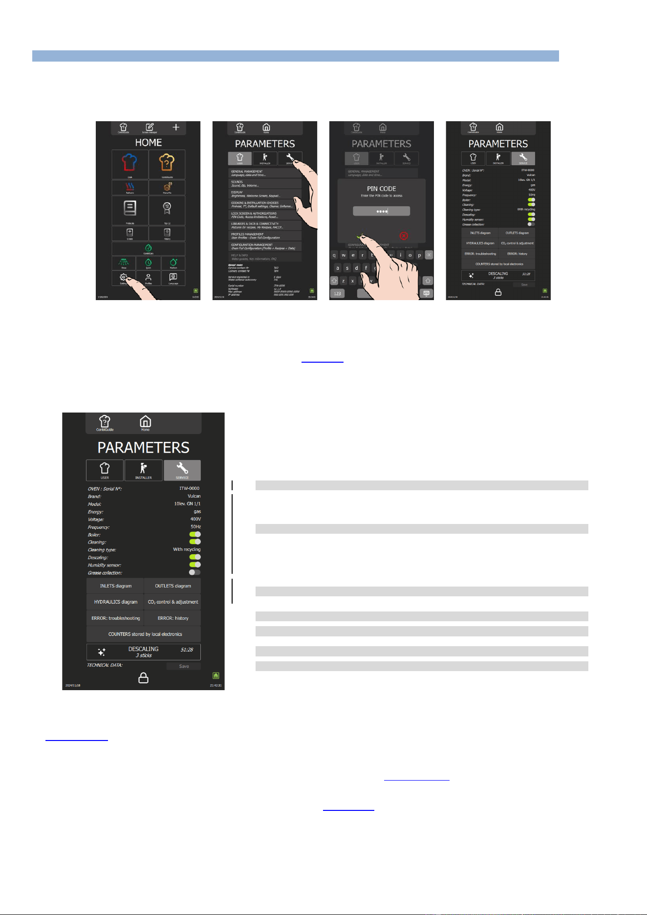
3.8 PARAMETERS SCREEN
For security reasons, the "Installer" and "Service" tabs are password-protected. You can permanently adjust your device's factory settings by pressing
the value of the parameter you want to change or activate. Once settings have been made, the parameters are adjusted immediately.
3.8.1 ACCESSING THE SERVICE SETTINGS MENU
» On the "Home" menu screen, select the "Parameters" button.
The screen displays "Parameters" menu with "User" tab selected.
» Select "Service" tab.
The PIN code identification pop-up appears.
» Enter PIN code (level 7) to access "Service" parameters (►PIN Codes).
» Validate by pressing « ✓ ». icon. If the code is correct, access to the screen is authorised; otherwise, return to
entering the PIN code.
3.8.2 LIST OF PARAMETERS
➔
Oven serial number
➔
Oven settings
➔
Maintenance diagrams
➔
Errors
➔
Counters
➔
Descaling the steam generator
➔
Save maintenance history: Button active if a USB key is connected to the oven
3.8.3 TROUBLESHOOTING ACCESS
Service screens: Input status screen, Output status screens and Hydraulics screen.
(►Troubleshooting - Maintenance screens)
Error: Troubleshooting
The screen displays the error table, starting with the first number listed in the error table (►Errors messages). To scroll through the numbers, use the
encoder to scroll to the desired number.
Alternatively, you can click on the number field to bring up the keypad and enter the desired target number directly.
You can access this screen by selecting an error line in the error history (►Error: History). When browsing the history, click on the specific error to be
automatically redirected to this screen. This feature enables efficient incident management, providing quick access to specific error details.
Error : History
The Error History screen provides a detailed view of incidents that have occurred, presented in chronological order from most recent to oldest. This
feature enables users to follow and understand the evolution of problems encountered by the Chef'sCombi.

3 - SETTINGS
CHEF’SCOMBI
Page 15 / 76
3VE490099EM – 10/25
Error messages are recorded in the history for a set period of 6 months; ensuring reliable tracking of incidents over an extended period.
Counters
The counter screen lists all the counters, with a history for the main counters. Following values for main counters, you will find the following values:
- The total value since the oven was switched on.
- Values for the last 7 days (D, D-1, D-2, D-3... D-7).
- Values for the last 12 months (M, M-1, M-2, M-3... M-12).
Note: Some counters can only display the current day's value, with no history of previous days.
List of counters
Designation
Units
Total operating time
Seconds
Cooking time convection mode
Seconds
Cooking time steam mode
Seconds
Cooking time combi mode
Seconds
Total time in cooking cycle
Seconds
Total time in cleaning cycle
Seconds
Hard water consumption
Millilitre
Softened water consumption
Millilitre
Elec. energy consumption
0.1Wmin
Gas energy consumption
0.1Wmin
Water consumption since last reset
Litre
Remaining water capacity
Litre
Hours elapsed since last service
Hours
Remaining hours before service
Hours
Cooking seconds elapsed since last cleaning
Seconds
Cleaning status
-
Number of completed cooking cycles
-
Number of completed cleaning cycles
-
Number of completed descaling cycles
-
Total operating time
Seconds
Cooking time convection mode
Seconds
Cooking time steam mode
Seconds
Cooking time combi mode
Seconds
Total time in cooking cycle
Seconds
Total time in cleaning cycle
Seconds
Hard water consumption
Litre
Softened water consumption
Litre
Elec. energy consumption
KWh
Gas energy consumption
KWh
Elec. energy consumption last cycle
KWh
Gas energy consumption last cycle
KWh
Water consumption last cycle
Litre
Duration last cycle
Seconds
Elec. energy consumption per cycle
KWh
Gas energy consumption per cycle
KWh
Water consumption per cycle
Litre
Average duration per cycle
Seconds
Elec. energy consumption last hour
KWh
Gas energy consumption last hour
KWh
Water consumption last hour
Litre
Average duration last hour
Seconds
Elec. energy consumption per hour
KWh
Gas energy consumption per hour
KWh
Water consumption per hour
Litre
Average duration per hour
Seconds
Total cleaning tabs consumption
-
Total descaling sticks consumption
-
Designation
Units
S01 CAVITY LIGHT (MOS)
-
S02 DAMPER (MOS)
-
S03 GREASE PUMP (MOS)
-
S04 DESCALING PUMP (RELAY)
-
S05 CAVITY DRAIN PUMP (RELAY)
-
S06 STEAM GENERATOR DRAIN PUMP (RELAY)
-
S08 TECH FAN (RELAY)
-
S09 KP (RELAY)
-
S10 POWER HEAT 1 (RELAY)
-
S11 POWER HEAT 2 (RELAY)
-
S12 POWER HEAT G (RELAY)
-
S13 CLEAN PUMP (RELAY)
-
S15 SPRAY VALVE (RELAY)
-
S16 DESCALER DISSOLUTION VALVE (RELAY)
-
S18 CONDENSER VALVE (OPTO)
-
S19 COOLING VALVE (OPTO)
-
S20 STEAM GENERATOR FILLING VALVE (OPTO)
-
S22 FAN OPERATION (TRIAC)
-
S23 FAN DIRECTION (RELAY)
-
SR1 COOKING STATE (RELAY)
-
S01 CAVITY LIGHT (MOS)
Seconds
S02 DAMPER (MOS)
Seconds
S03 GREASE PUMP (MOS)
Seconds
S04 DESCALING PUMP (RELAY)
Seconds
S05 CAVITY DRAIN PUMP (RELAY)
Seconds
S06 STEAM GENERATOR DRAIN PUMP (RELAY)
Seconds
S08 TECH FAN (RELAY)
Seconds
S09 KP (RELAY)
Seconds
S10 POWER HEAT 1 (RELAY)
Seconds
S11 POWER HEAT 2 (RELAY)
Seconds
S12 POWER HEAT G (RELAY)
Seconds
S13 CLEAN PUMP (RELAY)
Seconds
S15 SPRAY VALVE (RELAY)
Seconds
S16 DESCALER DISSOLUTION VALVE (RELAY)
Seconds
S18 CONDENSER VALVE (OPTO)
Seconds
S19 COOLING VALVE (OPTO)
Seconds
S20 STEAM GENERATOR FILLING VALVE (OPTO)
Seconds
S22 FAN OPERATION (TRIAC)
Seconds
S23 FAN DIRECTION (RELAY)
Seconds
SR1 COOKING STATE (RELAY)
Seconds
Descaling
Descaling enables the oven and steam generator to be descaled by force. Pressing the button starts a descaling process at the maximum level for the
oven without the cleaning program. The number of sticks required is clearly indicated and varies according to the oven model. The descaling process
is similar to that used for a wash with descaling and is carried out automatically.
Save
The save function automatically exports all the oven's essential parameters and data to a USB stick, organising them in different files for more efficient
management. Each type of data is saved in a separate file, including connectivity logs, errors, counters, cooking parameters and appliance
configuration. These files are automatically filed in a specific folder, created on the USB key, guaranteeing a complete and organised backup of
maintenance data.
The function is accessible if a USB stick is plugged into the USB socket.
4 - PREVENTIVE MAINTENANCE
CHEF’SCOMBI
Page 16 / 76
3VE490099EM – 10/25
4. PREVENTIVE MAINTENANCE
To ensure that your equipment operates safely and reliably over the long term, we recommend that you have it checked and serviced by our qualified
personnel.
The customer is automatically notified of the need for preventive maintenance. The overhaul counter is determined according to the frequency of use
of the oven and the number of hours between each intervention. These values must be entered by the technician at the time of installation and
checked at each service.
4.1 LIST OF ACTIONS
WARNING : The appliance must be disconnected from its power supply during cleaning or
maintenance, and when replacing parts.
Subject
Recommendations (Every year or every 3000h)
General
Earthing
Check the continuity of the earthing system
Oven position
Levelling, loading sill height, adjust if necessary.
Fixing the oven
If the appliance is fixed, check that it is correctly fixed.
Facia / Screen
Control panel sealing
Check that the control panel is watertight.If there are any leaks, make it watertight
Screen electronics / Interface board
No traces of dirt or dust deposits on the components - Clean and seal the compartment. - Check
that the screen is securely fastened to the bracket, as this ensures that it is watertight.
Screen connections
No traces of oxidation on the USB / RJ45 plug connectors - Replace if necessary.
Encoder board
No signs of dripping or oxidation - Check that it is working properly.
Encoder button
Check that it is in good condition and securely fixed, with no excessive play or wear, etc. - Replace
if necessary.
USB compartment / Spray hose
USB compartment
Check the condition of the USB socket: no deformation, no oxidation, check the closing flap, good
general condition, closing spring working, compartment completely sealed - Replace if
necessary.
Spray hose
Check the condition of the spray hose: no blockages, no leaks - dismantle and clean - Check the
supply pipe: no leaks, no cracks in the pipe - Check the reel: secure and return spring in good
working order - Replace if necessary.
Technical compartment
Air vents / technical fan
Clean the inlets - Clean the fan blades
Power supply terminals
Check that there are no signs of overheating - Tighten the connections
Fuse holders (if any)
Check that there are no signs of overheating - Tighten the connections
Contactors
Check that there are no signs of overheating - Tighten the connections
Main board
Remove dust - Check that there is no oxidation on the output contacts - Check the condition of
the fuses (visual check of the status LEDs) - Check that the connector screws are tight and that
they are correctly connected.
Valve In
Check the general tightness - Check the seal - Clean - Using the maintenance table, operate and
check that there is no noise, depending on the model, check the operation of the associated
motor, noise, etc. - Replace if necessary.
Heater
Ventilation motor
Using the maintenance table, operate the motor and check that there are no abnormal noises -
Systematically replace the motor shaft seal - Check that the mechanical fasteners are tight -
Lubricate the motor shaft (high-temperature lubricant).
Resistors
Check the condition of the supply wiring, cables in good condition, no cracks in the insulation.
Heat-shrink tubing present and in good condition. - Repair or replace if necessary.
Intensity measurement (convection heat
180°C)
Measure the current on each phase of each heating element and check that there is no imbalance
between phases and no drift from one test to the next. - Replace the element if necessary.
Gas or electric steam generator
Steam generator body
Descale if necessary (remove at least one immersion heater for visual inspection) - Replace the
seal - Check that there are no traces of dripping at the hydraulic connections.
Immersion heaters
Dismantle only if leaking - Replace seal - Check condition of wiring and heat-shrink tubing -
Repair or replace if necessary.
Intensity measurement (100°C steam heater)
Measure the current on each phase of each heating element and check that there is no imbalance
between phases and no drift from one test to the next. - Replace the element if necessary.
Level probe
Dismantle and clean - Check that the connections (probe and earth) are tight and that the thread
is watertight.
Hydraulic
General waterproofing
Carry out a visual check.
Water inlet
Cleaning the filter.
Solenoid valves
Check that there is no indication of overheating in the coils (change of colour if necessary) -
Check operation using the maintenance menu, leave the solenoid valves operating and check
the various circuits, seals, tightness of connections, etc. - Re-seal or replace the hoses if
necessary, and the solenoid valves if necessary.
Cleaning / descaling circuit
Check the condition of the descaling box: that the descaling flap is working properly, and that the
grille is clean and in good condition - clean if necessary.
Check the condition of the pipework: connections, hoses, no leaks.
Check the pump: using the maintenance menu, turn it over and check that there are no abnormal
noises, no leaks, and that the electrical connections are free from gap or oxidation. Replace if
necessary.
Check that there are no foreign bodies in the tank.
4 - PREVENTIVE MAINTENANCE
CHEF’SCOMBI
Page 17 / 76
3VE490099EM – 10/25
Subject
Recommendations (Every year or every 3000h)
Hydraulic
Steam generator drain circuit
Check the condition of the pipework: connections, hoses, no leaks.
Check the pump: using the maintenance menu, turn it over and check that there are no abnormal
noises, no leaks, and that the electrical connections are free from gap or oxidation. Check for
leaks or replace the pump if necessary.
Clean box drain circuit
Check the condition of the pipework: connections, hoses, no leaks.
Check the pump: using the maintenance menu, turn it over and check that there are no abnormal
noises, no leaks, and that the electrical connections are free from gap or oxidation. Check for
leaks or replace the pump if necessary.
Cleaning pump
Lubricate the bottom bearing of the pump with WD40 type lubricant product.
Cavity
General condition
Check that there are no rust stains and that cleaning and descaling are effective.
Joint
Clean - Check general condition - Replace if necessary.
Core probe
Check the general condition (tip, cable) - Check that the bulkhead feed-through is tight and
watertight - Check that it is working properly by starting a firing and checking the temperature
change.
20-level oven ventilation duct
Check that the lower axle ring is present and that it functions correctly (pivoting; hooking in).
Sprinkler
From the maintenance menu, activate the wash pump and visually check the water flow - Clean
the nozzles and retighten if necessary.
Water injection tube
Internal cleaning - Descaling if necessary - Changing the seal if necessary - Mechanical
fastening.
Drain
Check that the grille is clean, tight and watertight. Change the seal if necessary.
Under-door trunking
Check the drain and flue for leaks and cleanliness - Re-seal if necessary.
Ladders
Check that there is no corrosion and that the fixings and rails are in good condition. - Repair if
necessary.
Door
Top and bottom hinges
Check general condition (wear, etc.); Lubricate and tighten if necessary.
Internal door
Condition and presence of the door stops (complete if necessary); Check that the springs are
correctly pivoted and effective (adjust if necessary).
Lighting
General operation - Condition of label (must be watertight) - Clean - Replace if necessary
Door closing mechanism
Check clearances and general tightness - Check the state of wear of friction parts - Readjust if
necessary.
Bottom door seal (20 levels only)
Clean and check general condition - Replace if necessary.
Gas ovens only
Gas connection
If the connection is made with a flexible hose, check its suitability for use (date, condition, etc.) -
Replace if necessary
Gas pressure
Check the "static" and "dynamic" pressures at the appliance inlet - Adjust if necessary.
Combustion
Refer to the installation manual to carry out this check.
Exchangers
Visually check the general condition and tightness of the flanges in relation to the technical
compartment - Check the fixing points.
Ignition control / Flame safety / Burner motor
speed
Carry out the checks suggested by the technical screen in the maintenance menu before any
dismantling - Observe the results and, if necessary, follow the appropriate procedure.
Tightness of the gas circuit
Using a product such as "Mille Bulles", check the tightness of the connections upstream of the
gas valves and downstream of each connection when the burner is operating.
Safety checks
Switch off the gas supply while the burner is operating - The burner must go into safety mode
Plastic fireplaces
Check their presence and condition and clean if necessary.
Gas valves
Check: tightening of electrical control retaining screws, condition of metal hoses, tightness of
connections, etc. - Readjust in accordance with the instructions in this manual - Replace if
necessary.
Burner motor
Check during operation that there are no abnormal noises - Replace if necessary.
Grease collection option
Grease pump
Check the general condition, in particular that there are no leaks or drips, and that the electrical
connections are in good condition: no overheating, no traces of oxidation, etc. Using the
maintenance menu, run the motor and check that there are no noises - Replace if necessary.
Circuit
Check the condition of the pipes: no leaks, no cracks, no brittleness, no deformation or
blockages. - Replace defective parts if necessary.
Valve
Check general condition: no excessive gap at the handle, tightness of connections. - Replace if
necessary.
Safety valve
Check that it is working: close the grease outlet valve and activate the pump, the valve will
discharge the liquid - If not, replace the valve.
Safety pressure switch
Check that it is working: close the grease outlet valve and activate the pump. The pump should
stop and an error message should appear on the display. If this is not the case, replace the
pressure switch.
4 - PREVENTIVE MAINTENANCE
CHEF’SCOMBI
Page 18 / 76
3VE490099EM – 10/25
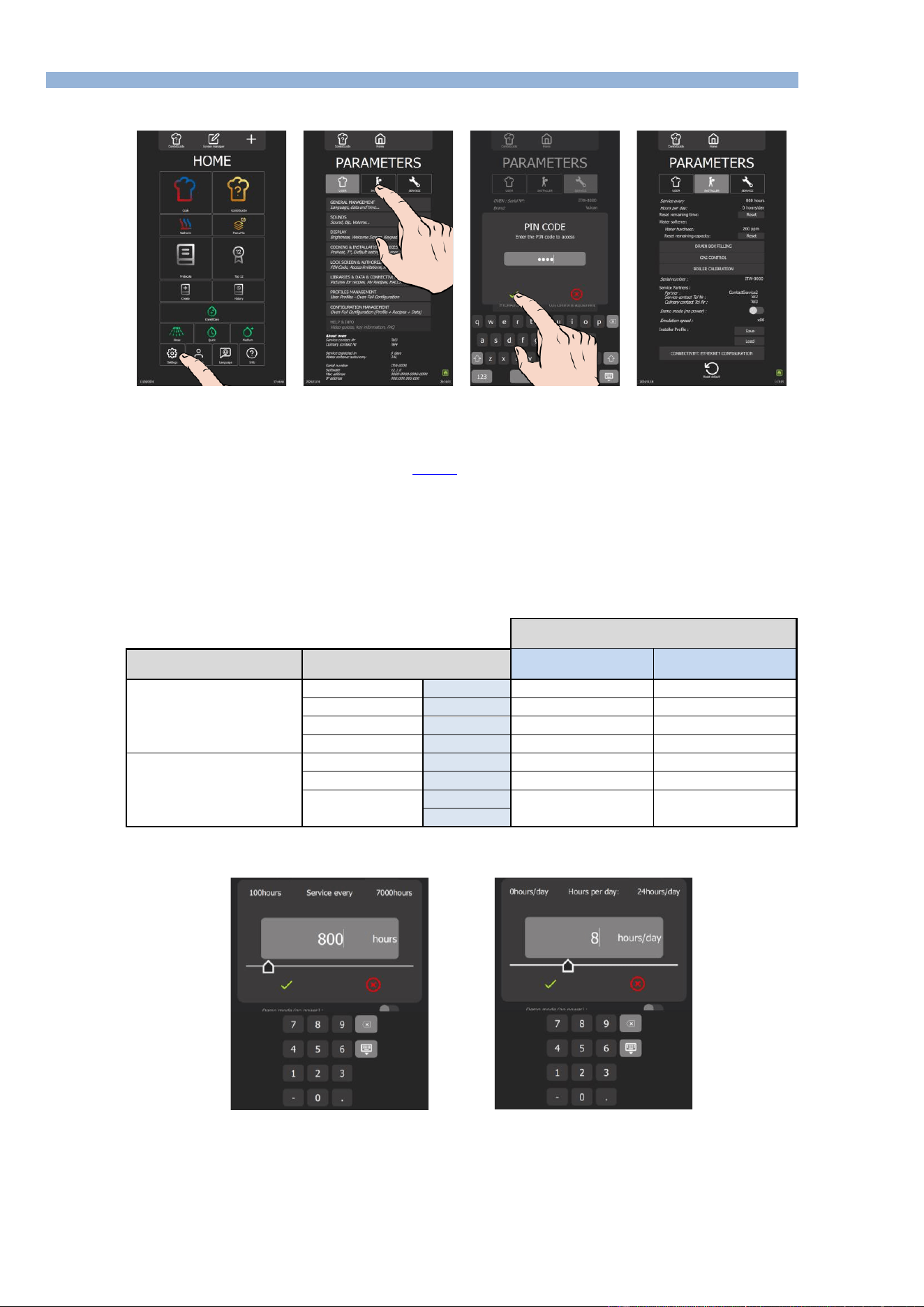
4.2 SETTING MAINTENANCE INTERVENTION FREQUENCY, DAILY USAGE RATE
Access to the Installer parameters menu
» From the "Home" menu screen, select the "Settings" button.
The screen displays the "Parameters" menu with the "User" tab selected.
» Select the "Installer" tab.
The PIN code identification pop-up appears.
» Enter PIN code (level 5 or 7) to access the "Installer" (►Settings - PIN Codes).
» Confirm by pressing "✓ " icon. If the code is correct, access to the screen is authorised; if not, return to entering
the PIN code.
Frequency of maintenance work and rate of use per day
The frequency of maintenance interventions and the rate of use per day are calculated in the table below according to the information supplied by the
customer at the time of installation, such as the number of hours the appliance is used per day and the type of cooking performed.
It is the responsibility of the technician to check that these settings correspond to the actual use of the oven, and to modify them if necessary
(according to the table below):
Setting the installation parameters
(to be entered in the Installation parameters)
Type of use
(Customer information)
Hours of use / day
(Customer information)
Maintenance every
(in hours)
Hours per day*
(in hours)
NORMAL USE
(Restaurants, etc.)
LIGHT
< 7 h
2000
6
STANDARD
7-12 h
3000
8
INTENSIVE
12-17 h
3000
16
VERY INTENSIVE
17-24 h
3000
24
COOKING >428°F
and/or
COOKING FATTY
PRODUCTS
(e.g. chicken rotisserie)
STANDARD
< 7 h
3000
8
INTENSIVE
7-12 h
3000
16
VERY INTENSIVE
12-17 h
3000
24
17-24 h
* hours of use
Frequency of maintenance
Number of hours / day
» Press number of hours input box.
The screen displays a keypad and the number entry field.
» Enter number of hours before the next maintenance (800h by default): Adjustable from 100 to 7000 hours. It's
essential that you plan to have your appliance serviced at least once a year.
- Select the area of the value to be modified.
- Set the value using the encoder knob or the keypad.
» Confirm by pressing "✓ " icon.
» Select box to enter number of hours of use per day.

4 - PREVENTIVE MAINTENANCE
CHEF’SCOMBI
Page 19 / 76
3VE490099EM – 10/25
The screen displays a keypad and the number entry field.
» Enter average hours appliance is in use each day. NOTE: This can be adjusted from 0 to 24 hours.
- Select area of the value to be modified.
- Set value using the encoder knob or the keypad.
» Confirm by pressing "✓ " icon.
Resetting the counter
» Reset the counter
- Press the "Reset" button.
» Confirm by pressing "✓ " icon.
5 - TROUBLESHOOTING
CHEF’SCOMBI
Page 20 / 76
3VE490099EM – 10/25
5. TROUBLESHOOTING
5.1 TROUBLESHOOTING METHOD
Before replacing components without being certain of the problem, it is important to use all the tools
supplied with the oven to target the real problem: error history, counters, error message and associated
solutions, test using the technical screens, check the status of the LEDS, etc…
1. Interview the customer:
o Collect as much information as possible from the user about the problems encountered (frequency, anomalies, blocking errors,
etc.).
2. Identify the problem:
o Check combi steamer is correctly supplied with electricity or gas, water and drain, depending on the type of model used.
o Visually inspect interior of the oven for signs of possible damage or obstructions.
o Check the indications potentially provided by the Chef'sCombi: the error history, counters, … may give indications of the type of
problem encountered, its frequency ….
o Write down the details of the problem encountered, for better understanding.
3. If an error message is displayed: Fault search with ERROR MESSAGE
o Follow instructions given in the error message.
o Refer to error table in this manual if necessary for further information on the specific error code encountered (►Troubleshooting -
Errors messages).
4. If no error message is displayed:
o Fault-finding via the maintenance screens
❖ Check different components via the maintenance screens of outlets, inlets and hydraulics in the maintenance
parameters of the oven interface (►Troubleshooting - Maintenance screens).
❖ Refer to this manual to understand their meaning.
❖ Write down any anomalies and proceed with troubleshooting.
o Fault-finding via communication LEDs
❖ Identify LEDs on the oven boards (►Troubleshooting - Communications LEDs).
❖ Refer to the LED guide to understand their meaning (►Troubleshooting - Communications LEDs).
❖ Proceed with troubleshooting.
o Fault-finding OTHER:
❖ Consult the manual to access available diagnostics (►Troubleshooting - Other symptoms).
❖ Follow the flow charts provided to diagnose the problem and identify the appropriate troubleshooting steps
(►Troubleshooting - Flow charts).
❖ Consult the electrical diagrams (►Electric diagrams).
5. Contact technical support if necessary:
o If the problem persists or if you are unable to solve the problem using the above steps, contact the manufacturer's technical
support. Please always direct service questions to combi.tech@vulcanequipment.com or (800) 814-2028, select prompt #2, then
#8.
o Give all the relevant information you have collected during diagnosis for effective assistance.
5.2 ERRORS MESSAGES
To facilitate the intervention, hang the Main board in the maintenance position (►Access to
components – Maintenance position of the Main board assembly).
Code
Title
Probable Causes
What to do?
E00
Cavity overheat greater than 626°F
Control contacts stuck.
POWER OFF: Using an ohmmeter, place the test probes on
the terminal clamping screws to check the resistance between
L and T for each pole of the Kr contactor(s). The value must be
equal to “OL”; if not, replace the faulty contactor(s).
Output S10 of the Main board permanently
activated.
POWER OFF: Using an ohmmeter, place the test probes on
the terminal clamping screws and check the continuity between
the “230Vac” terminal of connector J15 and the “S10” output of
connector J16 on the Main board.
If there is continuity, replace the Main board.
Output S11 of the Main board permanently
activated (gas ovens 20 levels only).
POWER OFF: Using an ohmmeter, place the test probes on
the terminal clamping screws and check the continuity between
the “230Vac” terminal of connector J15 and the “S11” output of
connector J16 on the Main board.
If there is continuity, replace the Main board.
To reset this fault, the power supply to the oven must be cut off by disconnecting the associated protection circuit breaker.
E01
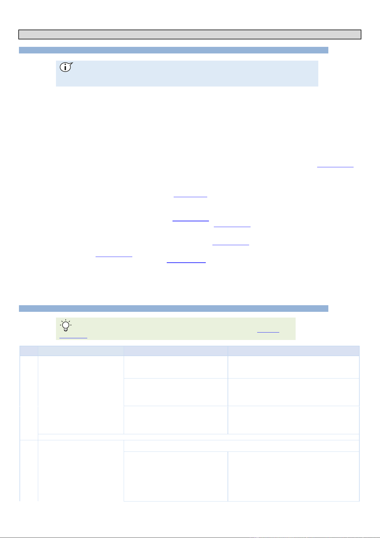
Ambient probe cavity fault.
Open “Inlets Diagram” in the “Service” screen and check the temperature indicated by the ‘Ban’ ambient probe. If
the value is “-°F,” the sensor circuit is faulty (short-circuited or open). Check the following points:
Wire broken in probe or input connection "Ban"
POWER OFF: check that the connector is properly inserted into
its socket and that each wire is connected to each terminal on
the connector. If the problem persists, disconnect the Pt100
“Ban” probe from connector J2 on the Main board and measure
between the two white wires using an ohmmeter. (By example,
the température of the cavity is between 70°F and 80°F, the
measured value will be between 108 Ω and 110 Ω). If the
measured value is “OL,” the circuit is open. Repair the
connection, or replace the sensor.

5 - TROUBLESHOOTING
CHEF’SCOMBI
Page 21 / 76
3VE490099EM – 10/25
Code
Title
Probable Causes
What to do?
Short circuit in the probe or probe input
connection "Ban"
POWER OFF: check that the connector is properly inserted into
its socket and that each wire is connected to each terminal on
the connector. If the problem persists, disconnect the Pt100
“Ban” probe from connector J2 on the Main board and measure
between the two white wires using an ohmmeter. (By example,
the temperature of the cavity is between 70°F and 80°F, the
measured value will be between 108 Ω and 110 Ω). If the value
measured is less than 100 Ω, there is a short circuit. Repair the
connection, or replace the probe.
Main board electrical fault
POWER OFF: if the probe and its connection are working,
replace the Main board.
To reset this fault, the power supply to the oven must be cut off by disconnecting the associated protection circuit breaker.
E02
Ambient probe cavity fault.
Wire broken in probe or input connection "Baa"
POWER OFF: check that the connector is properly inserted into
its socket and that each wire is connected to each terminal on
the connector. If the problem persists, disconnect the Pt100
“Baa” probe from connector J2 on the Main board and measure
between the two white wires using an ohmmeter. (By example,
the température of the cavity is between 70°F and 80°F, the
measured value will be between 108 Ω and 110 Ω). If the
measured value is “OL,” the circuit is open. Repair the
connection, or replace the probe.
Short circuit in the probe or probe input
connection "Baa"
POWER OFF: check that the connector is properly inserted into
its socket and that each wire is connected to each terminal on
the connector. If the problem persists, disconnect the Pt100
“Baa” probe from connector J2 on the Main board and measure
between the two white wires using an ohmmeter. (By example,
the temperature of the cavity is between 70°F and 80°F, the
measured value will be between 108 Ω and 110 Ω). If the value
measured is less than 100 Ω, there is a short circuit. Repair the
connection, or replace the probe.
Main board electrical fault
POWER OFF: if the probe and its connection are working,
replace the Main board.
To reset this fault, the power supply to the oven must be cut off by disconnecting the associated protection circuit breaker.
E10
Steam generator scale.
Water hardness is incorrectly set in the installation
parameters
Measure the water hardness and adjust the hardness
parameter in the installation settings. Carry out descaling cycle
from the "Service" screen.
Defective water softener or water filter
Measure water hardness and check or have checked that the
water softener and the water filter are working properly. Carry
out descaling cycle from the "Service" screen.
Limescale has built up in the steam generator and
the recommended descaling cycles have not
been carried out.
Carry out descaling cycle from the "Service" screen.
E11
High level of steam generator scale.
Water hardness is incorrectly set in the installation
parameters
Measure the water hardness and adjust the hardness
parameter in the installation settings. Carry out descaling cycle
from the "Service" screen,
Defective water softener or water filter
Measure water hardness and check or have checked that the
water softener and the water filter are working properly. Carry
out descaling cycle from the "Service" screen,
Limescale has built up in the steam generator and
the recommended descaling cycles have not
been carried out.
Carry out descaling cycle from the "Service screen".
E12
Steam generator overheat greater than
266°F
The Steam generator is heating; however, the
water level is low: The water level controller is
faulty.
Check the functionality of the water level control "BnC" from
"Inlets diagram" in the "Service" screen:
=> If the control probe is immersed in water, BnC = 1
=> If the control probe is not in water, BnC = 0.
If not functioning, check the state (Presence of calcium; Mineral
fouling...).
Steam generator heats even though water level is
too low: Sensor connection short-circuited or
grounded.
Disconnect the connector J1 on the Main board and take a
reading between the terminals "BnC" and "EARTH" using an
ohmmeter; If there is a short circuit, the ohmmeter indicates a
value close to “0” Ω, then locate the fault and repair as required.
The Steam generator is heating; however the
water level is low: Input "BnC" at the Main board
is defective.
Replace the Main board
E13
Steam generator temperature probe fault
Open “Inlets diagram” in the “Maintenance” screen and check the temperature indicated by the "Bgn" steam
generator probe. If the value is “-°F”, the sensor circuit is faulty (short-circuited or open). Check the following points:
Wire broken in probe or input connection "Bgn"
POWER OFF: check that the connector is properly inserted into
its socket and that each wire is connected to each terminal on
the connector. If the problem persists, disconnect the Pt100
"Bgn" sensor from connector J2 on the Main board and
measure between the two white wires using an ohmmeter. (By
example, the température is between 70°F and 80°F, the
measured value will be between 108 Ω and 110 Ω). If the
measured value is “OL,” the circuit is open. Repair the
connection, or replace the probe.
Short circuit in the probe or probe input
connection "Bgn"
POWER OFF: check that the connector is properly inserted into
its socket and that each wire is connected to each terminal on
the connector. If the problem persists, disconnect the Pt100
“Bgn” probe from connector J2 on the Main board and measure
between the two white wires using an ohmmeter. (By example,
the température is between 70°F and 80°F, the measured
value will be between 108 Ω and 110 Ω). If the value read is
less than 100 Ω, there is a short circuit. Repair the connection,
or replace the probe.

5 - TROUBLESHOOTING
CHEF’SCOMBI
Page 22 / 76
3VE490099EM – 10/25
Code
Title
Probable Causes
What to do?
Main board electrical fault
POWER OFF: If the probe and the connections are functioning,
replace the Main board.
E14
Steam generator temperature probe
fault.
Wire broken in probe or input connection "Bga"
POWER OFF: check that the connector is properly inserted into
its socket and that each wire is connected to each terminal on
the connector. If the problem persists, disconnect the Pt100
“Bga” sensor from connector J2 on the Main board and
measure between the two red wires using an ohmmeter. (By
example, the température is between 70°F and 80°F, the
measured value will be between 108 Ω and 110 Ω). If the
measured value is “OL,” the circuit is open. Repair the
connection, or replace the probe.
Short circuit in the probe or probe input
connection "Bga"
POWER OFF: check that the connector is properly inserted into
its socket and that each wire is connected to each terminal on
the connector. If the problem persists, disconnect the Pt100
“Bga” probe from connector J2 on the Main board and measure
between the two red wires using an ohmmeter. (By example,
the température is between 70°F and 80°F, the measured
value will be between 108 Ω and 110 Ω). If the value read is
less than 100 Ω, there is a short circuit. Repair the connection,
or replace the probe.
Main board electrical fault
POWER OFF: If the probe and the connections are functioning,
replace the Main board.
To reset this fault, the power supply to the oven must be cut off by disconnecting the associated protection circuit breaker.
E15
The level of water in the steam generator
has not been reached after 117 seconds.
Water supply closed
Check that the water supply in-line valves are open
Water pressure too low
Mesure the water pressure at the oven connection. When the
water supply to the oven is maximum, the pressure must be
greater than 1.5 bar.
The Steam generator is not being fed water: The
fuse "F1" of the Main board has blown (LED "800"
off (►LEDs identification))
Check the cause of blowing, and the state of condenser's
solenoids (Ycond.) and cooling's solenoid (Ycool). Make the
repear and change the fuse by a fuse of the same models.
The Steam generator is not being supplied water:
The output "S20" of the Main board is faulty.
Press the "Yboiler" button from "Hydraulics diagram" in the
"Service" screen, and measure the voltage between the output
"S20" of the Automate and terminal "Xb". If the voltage is less
than 230V, change the Main board.
Steam generator is not being supplied water:
Then steam generator fill solenoid valve is
defective.
WARNING: The ouput is controlled by a triac: a voltage at the
output can be measured even if the triac is not open.
The Steam generator is not being supplied water:
Then Steam generator fill solenoid valve is
defective.
Disconnect the water supply pipe from the steam generator at
the elbow and place it in a container. Press the “Yboiler” button
from “Hydraulics Diagram” in the ‘Service’ screen, and check
that water is coming out of the pipe. If no water is flowing, the
“Yboiler” steam generator fill solenoid valve is defective and
must be replaced.
Water flow rate too low.
Disconnect the water supply hose from the steam generator at
the elbow and place it in a container. Press the “Yboiler” button
from “Hydraulics Diagram” in the “Service” screen and let the
water run into the container for as long as the solenoid valve is
open (1 minute). The amount of water collected should be
approximately 1,3 gallons. If it is less than this, check the
condition of the filters and flow limiter in the solenoid valve
(clogging, etc.). Clean them or replace the solenoid valve.
E16
Steam generator drainage pump fault.
24/230Vac supply voltage input fault
With a voltmeter, check the supply voltage between input
24/230Vac of the Main board and terminal "Xb". This voltage
should be 230V (120V on ovens version "UL"). If not, find the
cause of the fault and repair as required.
Fuse F4 blown (LED "702" off (►LEDs
identification))
Find the cause of the blowing, check the state of the descaling
pump (Mdg) and the cavity drain pump (Mvm). Make repairs
and replace the fuse with the same model.
Fault with the Main board switch S06
Connect a voltmeter between the terminal S06 of the Main
board and terminal Xb. Activate relay output S06 from "Outlets
diagram" in the "Service" screen. If the voltage reads zero
when the relay is operated, replace the Main board.
The drainage pump is not powered
Connect a voltmeter to the terminals of the Steam generator
drain pump (Mvg). Activate relay output S06 from "Outlets"
diagram in the "Service" screen. If the voltage reads zero when
the relay is operated, check the pump cabling and repair as
required.
Steam generator drainage pump defective or
blocked.
Activate relay output S06 from "Outlets" diagram in the
"Service" screen. If the pump does not function, visually check
its state: clean or swap out as required.
Steam generator water level control failure
Check the operation of the “BnC” water level control from the
“Inlets diagram” in the "Service" screen: if water is present, BnC
= 1; if the probe is out of the water, BnC = 0.
If this is not the case, check the condition of the probe
(limescale, dirt) and its electrical connection. If the probe is
working, replace the Main board.
E20
The level of water in the cleaning tank
has not been reached after 50 seconds.
Water supply closed
Open the water supply
Water pressure too low
Check the water pressure at the oven connection. During
maximum kitchen water use, the pressure must be greater than
1.5 bar.
Water flow rate too low.
Check the state of the filter and of the condenser flow limiting
solenoid valve (Fouling...). Clean if required. The water flow
rate should be approximately 5l/min.

5 - TROUBLESHOOTING
CHEF’SCOMBI
Page 23 / 76
3VE490099EM – 10/25
Code
Title
Probable Causes
What to do?
Fuse F1 blown ( LED "702" off (►LEDs
identification))
Find the cause of the blowing, check the state of the Ycond and
Yboiler solenoid valves. Carry out repairs and replace the fuse
with the same model.
Fault with the Main board output S18
Connect a voltmeter between the terminal S18 of the Main
board and terminal Xb. Activate relay output S18 from "Outlets
diagram" in the "Service" screen. If the voltage is zero when the
output is activated, replace the Main board. WARNING: The
output is controlled by a triac: a voltage can be read at the
output, even when the triac is not open.
The condenser solenoid valve (Yc) is not
powered.
Connect a voltmeter to the terminals of the condenser solenoid
valve (Ycond). Activate relay output S18 from "Outlets diagram"
in the "Service" screen. If the voltage reads zero when the
output is operated, check the solenoid valve cabling and repair
as required.
Condenser solenoid valve defective
Activate output S18 from "Outlets diagram" in the "Service
screen". If the solenoid valve does not function, then replace.
Cleaning box water level control failure
Check the operation of the “BnL” water level control from the
“Inlets diagram” in the "Service" screen: if water is present, BnL
= 1; if the probe is out of the water, BnL = 0.
If this is not the case, check the condition of the probe
(limescale, dirt) and its electrical connection. If the probe is
working, replace the Main board.
E21
Cleaning box drainage pump fault
24/230Vac supply voltage input fault
With a voltmeter, check the supply voltage between input
24/230Vac of the Main board and terminal "Xb". This voltage
should be 120V on ovens. If not, find the cause of the fault and
repair as required.
Fuse F4 blown (LED "702" off (►LEDs
identification))
Find the cause of blowing, check the state of the descaling
pump (Mdg) and the cavity drainage pump (Mvm). Repair by
replacing the fuse with the same model.
Fault with the Main board switch S05
Connect a voltmeter between the terminal S05 of the Main
board and terminal Xb. Activate relay output S05 from "Outlets
diagram" in the "Service" screen. If the voltage reads zero
when the relay is operated, replace the Main board.
The drainage pump is not powered
Connect a voltmeter to the terminals of the cavity drain pump
(Mvm). Activate relay output S05 from "Outlets diagram" in the
"Service" screen. If the voltage reads zero when the relay is
operated, check the pump cabling and repair as required.
Cleaning box drainage pump defective or blocked
Activate relay output S05 from "Outlets diagram" in the
"Service" screen. If the pump does not function, visually check
its state: clean or swap out as required.
Cleaning box water level control failure
Check the operation of the “BnL” water level control from the
“Inlets diagram” in the "Service" screen: if water is present, BnL
= 1; if the probe is out of the water, BnL = 0.
If this is not the case, check the condition of the probe
(limescale, dirt) and its electrical connection. If the probe is
working, replace the Main board.
E22
Descaling pump cartridge fault.
24/230Vac supply voltage input fault
With a voltmeter, check the supply voltage between input 24-
/230Vac of the Main board and terminal "Xb". This voltage should
be 120V. If not, find the cause of the fault and repair as required.
Fuse F4 blown (LED "702" off (►LEDs
identification))
Find the cause of blowing check the state of the Steam
generator drainage pump (Mvg) and the cavity drainage pump
(Mvm). Repair by replacing the fuse with the same model.
Fault with the Main board switch S04
Connect a voltmeter between the terminal S04 of the Main
board and terminal Xb. Activate relay output S05 from "Outlets
diagram" in the "Service" screen. If the voltage reads zero
when the relay is operated, replace the Main board.
The descale pump is not powered
Connect a voltmeter to the terminals of the descaling pump
(Mdg). Activate relay output S04 from "Outlets diagram" in the
"Service" screen. If the voltage reads zero when the relay is
operated, check the pump cabling and repair as required.
Descaling tank drainage pump defective or
blocked
Activate relay output S04 from "Outlets diagram" in the
"Service" screen. If the pump does not function, visually check
its state: clean or swap out as required.
Steam generator water level control failure
Check the operation of the “BnC” water level control from the
“Inlets diagram” in the "Service" screen: if water is present, BnC
= 1; if the probe is out of the water, BnC = 0.
If this is not the case, check the condition of the probe
(limescale, dirt) and its electrical connection. If the probe is
working, replace the Main board.
E23
Cleaning pump fault
230Vac supply voltage input fault
With a voltmeter, check the supply voltage between input 230Vac
of the Main board and terminal "Xb". This voltage should be
230V. If not, find the cause of the fault and repair as required.
Fuse F2 of the main board blown (LED "702" off
(►LEDs identification))
Find the cause of blowing, check the status of the cleaning
pump (Mpn) and the solenoid valves for the hand shower
(Yspray) and/or descaling box filling (Ydescal.). Carry out
repairs and replace the fuse with the same model.
Fault with the Main board switch S13
Connect a voltmeter between the terminal S13 of the Main
board and terminal Xb. Activate relay output S13 from "Outlets
diagram" in the "Service" screen. If the voltage reads zero
when the relay is operated, replace the Main board.
The cleaning pump is not powered
Connect a voltmeter to the terminals of the cleaning pump
(Mpn). Activate relay output S13 from "Outlets diagram" in the
"Service" screen. If the voltage reads zero when the relay is
operated, check the pump cabling and repair as required.

5 - TROUBLESHOOTING
CHEF’SCOMBI
Page 24 / 76
3VE490099EM – 10/25
Code
Title
Probable Causes
What to do?
Cleaning pump defective or blocked
Activate relay output S13 from "Outlets diagram" in the
"Service" screen. If the pump does not function, visually check
its state: clean or swap out as required.
Clean wash box water level control failure
Check the water level control function from "Inlets diagram" in
the "Service" screen: if the probe is in the water, the BnL = 1,
and if it is out of the water, the BnL = 0.
If this is not the case, check the condition of the probe (scale;
dirt) and its electrical connection. If the probe is functional,
replace the Main board.
Cleaning pump capacitor faulty or incorrectly
connected
Check cleaning pump capacitor connection (lugs well plugged
in and no traces of oxidation). Switch off the oven, disconnect
the capacitor and connect a multi-meter in its place to check
the capacity of the 6.3µf (+/-5%) capacitor. If the value is
incorrect, replace the capacitor.
E30
Unpricked Core probe or Failed Core
Probe.
Check fault on the "Inlets diagram"
Open "Inlets diagram" in the "Service" screen and check the
temperature being indicated by the food probe "Bsc". If the
value is "---" at all points, the common point of the probe (Bsc
com) is faulty (either short-circuited or open).
Wire broken in probe or input connection Bsc
Com
Disconnect the probe Pt100 from the Main board and take
readings using an ohmmeter between points Bsc com and
Bsc1, Bsc2 and Bsc3; If the circuit is broken, repair the
connection. If not, replace the probe.
Short circuit in the probe or probe input
connection Bsc Com
Disconnect the probe Pt100 from the Main board and take
readings using an ohmmeter between points Bsc com and
Bsc1, Bsc2 and Bsc3; If there is a short circuit, locate the fault
and repair as required. If not, replace the probe.
Main board electrical fault
If the probe and the connections are functioning, replace the
Main board.
The extension lead between the Main board and
the probe is faulty
Check the ohmic values of each PT100 probe: measure the
values between the common (yellow wire) and each of the
other wires, compare the values with the values ( sse chapter
PT100 Probe) . Carry out this operation on the probe side and
on the board side. If the values differ, replace the extension
lead between the probe and the Main board.
E31
Food probe degraded.
Check fault on the "Inlets diagram"
Open "Inlets diagram" in the "Service" screen and check the
temperature being indicated by the food probe "Bsc". If one of
the values is "---", this point of the probe (Bsc1 => Bsc3) is
faulty (either short-circuited or open).
Wire broken in probe or the input connections Bsc
1 to 3
Disconnect the probe Pt100 from the Main board and take
readings using an ohmmeter between points Bsc com and
Bsc1, Bsc2 and Bsc3; If one of the test points is broken, repair
the connection. If not, replace the probe.
Short circuit in the probe or one of the probe input
connections Bsc 1 to 3
Disconnect the probe Pt100 from the Main board and take
readings using an ohmmeter between points Bsc com and
Bsc1, Bsc2 and Bsc3; If one of the test points has short
circuited, repair the connection. If not, replace the probe.
Main board electrical fault
If the probe is functioning, replace the Main board.
The extension lead between the Main board and
the probe is faulty
Check the ohmic values of each PT100 probe: measure the
values between the common (yellow wire) and each of the
other wires, compare the values with the values (see chapter
PT100 Probe) . Carry out this operation on the probe side and
on the board side. If the values differ, replace the extension
lead between the probe and the Main board.
E32
Food probe not inserted.
Probe not inserted in food, incorrect
measurement values
Insert the food probe, taking care to follow the instructions of
pricking.
E34
USB Core Probe unpricked or out of
service.
The probe is detected at the USB port but
temperature is not being measured.
Open "Inlets diagram" in the "Service" screen and check the
temperature being indicated by the food probe "USB". If the
value is "---" at all points, the probe is defective. Replace the
probe.
E35
USB food probe degraded.
One or more of the measured temperatures are
out of range.
Open "Inlets diagram" in the "Service" screen and check the
temperature being indicated by the food probe "USB". If the
value is "---" at one of the measuring points, the probe is
defective. Replace the probe.
E40
Gas safety device active on "convection"
cavity burner.
Gas inlet valve closed, no gas or Incorrect gas
type
Make sure that the gas supply is on. Check that the type of gas
being supplied conforms with that shown on the appliance's
specification plate. Open the gas valve
No grounding on power supply
Check the grounding of the device using a megohmmeter.
Check or have someone check the continuity of the ground and
the grounding.
Gas pressure too low
Measure the gas pressure by measuring from input of the gas
valve "Pin" (►Changing/adjusting gas valve) at the appliance
connection when all appliances running off the same supply are
operating at maximum capacity. The gas pressure must be
within the allowed limits.
Gas board output AL12 defective
Connect a voltmeter between the terminal AL12 of the add-on
gas board (Aag) and terminal Xb. Activate relay output AL12
from "Outlets diagram" in the "Service" screen. If the voltage
reads zero when the relay is operated, replace the add-on gas
board.
The spark box Ear (►Electric boards) is not
powered.
Connect a voltmeter to the terminals of the "convection" burner
spark box Ear. Activate relay output AL12 from "Outlets
diagram" in the "Service" screen. If the voltage reads zero
when the relay is operated, check the lighter cabling and repair
as required.

5 - TROUBLESHOOTING
CHEF’SCOMBI
Page 25 / 76
3VE490099EM – 10/25
Code
Title
Probable Causes
What to do?
The spark box Ear (►Electric boards) is
defective.
Activate output relay AL12 from "Outlets diagram" in the
"Service" screen. If the spark box Ear does not function, then
replace.
The gas board (Aag) is received a signal from the
safety box "Avr1" on SECU12 input on the gas
board "Aag".
Check if flame sensor is properly connected to the safety box
"Avr1". If properly connected, replace the safety box "Avr1".
Incorrect spacing of the gas flame sensor
Check the spacing of ignition electrodes and flame sensor.
The input PF1 (or PF2 on oven 20N) of the gas
add-on board is defective
Changing the add-on gas board (Aag)
E41
Gas safety device active on steam
generator burner.
Gas inlet valve closed, no gas or incorrect gas
type
Make sure that the gas supply is on. Check that the type of gas
being supplied conforms with that shown on the appliance's
specification plate. Open the gas valve
No grounding on power supply
Check the grounding of the device using a megohmmeter.
Check or have someone check the continuity of the ground and
the grounding.
Gas pressure too low
Measure the gas pressure by measuring from input of the gas
valve "Pin" (►Changing/adjusting gas valve) at the appliance
connection when all appliances running off the same supply are
operating at maximum capacity. The gas pressure must be
within the allowed limits.
If not, adjust the gas pressure or increase the capacity of the
gas supply (Expansion valve, pipe diameter).
Gas board AL3 output defective
Connect a voltmeter between the terminal AL3 of the add-on
gas board (Aag) et une terminal Xb. Operate the output relay
AL3 from "Outlets diagram" in the "Service" screen. If the
voltage reads zero when the relay is operated, replace the add-
on gas board.
The spark box Eag (►Electric boards) is not
powered.
Connect a voltmeter to the terminals of the Steam generator
burner spark box Eag. Operate the output relay AL3 from
"Outlets diagram" in the "Service" screen. If the voltage reads
zero when the relay is operated, check the lighter cabling and
repair as required
The spark box Eag (►Electric boards) is
defective.
Activate relay output AL3 from "Outlets diagram" in the
"Service" screen. If the Steam generator burner spark box Eag
does not function, then replace.
The gas board (Aag) is received a signal from the
safety box "Avg" on SECU3 input on the gas
board "Aag".
Check if flame sensor is properly connected to the safety box
"Avg". If properly connected, replace the safety box "Avg".
Incorrect spacing of the gas flame sensor
Check the spacing of ignition electrodes and flame sensor.
The input "PF3" of the gas add-on board is
defective.
Changing the add-on gas board (Aag)
E50
Humidity sensor faulty (This error only
appears when the oven is cooking not
preheating).
Open “Inlets diagram” on the “Service" screen and check the humidity value delivered by the sensor. This must be
greater than 3%. If this is not the case, check the following points:
The F2 fuse on the “Ahu” humidity additional
board (►Humidity board) is blown, (LED 100 off
(►LEDs identification))
Find the cause of the blowing and replace the fuse by the same
model.
The "Humidity" add-on board (Ahu) is not
powered.
Check the flashing of the communication LED "green" and
"orange" on the board. If they do not flash, use a voltmeter to
check that the board is powered (Set to DC current). This must
be +24Vdc
The "Humidity" add-on board (Ahu) is not
communicating with the Main board.
Check the flashing of the communication LED "green" and
"orange" on the board. If they do not flash, change the add-on
board
The J2 connector on the Ahu “Humidity”
additional board is not properly inserted into its
socket, or the wires are not properly connected in
the connector.
Check the connections on connector J2 of the AHU “Humidity”
additional board, check that the connector screws are tight, and
check that the extension connector is properly connected to the
sensor connector.
The humidity probe is defective
Check the status of the LEDs: if the “200” LED is flashing red or
steady red, replace the humidity sensor (►Communication
LEDs)
E60
Internal oven fan not functioning
Before resolving error E60, please refer to the "error history" on the “Service” screen and check that no other error
codes are displayed. If any are displayed, correct these errors first.
The fuse "Ftmv" is blown
Find the cause of the blowing and replace by the fuse with the
same model
The fuse F3 of the Main board (►Main board)
has blown (LED "701" off (►LEDs identification))
Find the cause of the blowing and replace by the fuse with the
same model.
The fuse Fm (located in the black cylindrical fuse
holder near connector J22) of the Main board
(►Main board) has blown (LED "801" off
(►LEDs identification)) This LED lights only when
the contactor Kp is on
Find the cause of the blowing and replace by the fuse with the
same model.
The fan motor thermal protection is open
POWER OFF, check the continuity of the circuit between the
terminal A2 of the contactor Kp and terminal Xb. If the circuit is
broken, check the cabling or change the motor.
The main contactor Kp is not powered
Connect a voltmeter between the terminals A1 and A2 of the
main contactor Kp. Activate relay output Kp from "Outlets
diagram" in the "Service" screen. If the voltage reads zero
when the relay is operated, check the contactor Kp cabling or
replace the Main board.
The main contactor Kp is defective
Connect a voltmeter between the terminals A1 and A2 of the
main contactor Kp. Operate the output Kp from "Outlets
diagram" in the "Service" screen. If the main contactor Kp does
not close when powered, replace the contactor.

5 - TROUBLESHOOTING
CHEF’SCOMBI
Page 26 / 76
3VE490099EM – 10/25
Code
Title
Probable Causes
What to do?
The motor is not powered
POWER OFF: check the motor connector (it is properly
engaged in the socket, the connections are secure, etc.).
POWER ON: connect a voltmeter between the terminals Xm1
and Xm0. Operate the output switch Kp from "Outlets diagram"
in the "Service" screen. If the voltage is not between 208V et
240V, inspect the cabling.
Motor circuit cut
POWER OFF, check the continuity of the circuit between the
outputs S22 and S23 of the Main board and the terminal Xm0.
If the circuit is open (the measurement indicated is "OL"), check
the cabling or change the fan motor.
Short-circuited Triac motor
POWER OFF: measure the continuity between terminals E21
and S22 on the Main board. If they are short-circuited, the
ohmmeter will indicate a value close to “0” Ω. If this is the case,
replace the Main board.
To reset this fault, the power supply to the oven must be cut off by disconnecting the associated protection circuit breaker.
E70
Electronics overheat: temp. greater than
or equal to 149°F.
Ambient temperature around oven too high
The oven is not getting enough fresh air: clean the air intake
vents (►Location of technical components), check the
installation, and move any appliances that generate a lot of
heat, such as open burners or hot plates, away from the oven.
It may be necessary to install an optional heat shield.
Air inlets require cleaning
Clean the cool air intake vents
Technical fan(s) require(s) cleaning
Clean the technical fan(s)
The fuse F3 of the Main board (►Main board)
has blown (LED "701" off (►LEDs identification))
Find the cause of blowing and replace with fuse of the same
model.
The output S08 in J16 connector of the Main
board is defective.
Connect a voltmeter between the terminal S08 of Main board and
a Xb terminal. Activate relay output S08 from "Outlets diagram" in
the "Service" screen. If there is no voltage, replace the Main board.
In electrical oven only, the output S091 in J16
connector of the Main board is defective.
Connect a voltmeter between the terminal S091 of Main board et a
Xb terminal. Activate relay output S091 from "Outlets diagram" in
the "Service" screen. If there is no voltage, replace the Main board.
The technical fan(s) is (are) not powered
Connect a voltmeter between the terminals ventilator power
supply. Activate relay output S08 from "Outlets diagram" in the
"Service" screen. If the voltage reads zero, inspect the cabling.
On electric's ovens only, do the same operation with the S091
output. From "Outlets diagrams in the "Service" screen, activate
Kp, if the voltage between the terminal fan connexions is "0"V,
check the wiring.
The technical fan(s) is defective
Activate relay output S08 from "Oven diagram" in the "Service"
screen. If the fan does not turn, then replace. On electric ovens
only, activate output S091 by pressing on "Kp" from "Outlets
diagram" in "Service" screen then the second fan must run. If it
does not turn, replace it.
E71
Electronics overheat: temp. greater than
or equal to 158°F.
Ambient temperature around oven too high
The oven is not getting enough fresh air: clean the air intake
vents (►Location of technical components), check the
installation, and move any appliances that generate a lot of
heat, such as open burners or hot plates, away from the oven.
It may be necessary to install an optional heat shield.
Air inlets require cleaning
Clean the cool air intake vents.
Technical fan(s) require(s) cleaning
Clean the technical fan(s).
The fuse F3 of the Main board (►Main board)
has blown (LED "701" off (►LEDs identification))
Find the cause of blowing and replace with fuse of the same
model.
The output S08 in J16 connector of the Main
board is defective.
Connect a voltmeter between the terminal S08 of Main board and
a Xb terminal. Activate relay output S08 from "Outlets diagram" in
the "Service" screen. If there is no voltage, replace the Main board.
In electrical oven only, the output S091 in J16
connector of the Main board is defective.
Connect a voltmeter between the terminal S091 of Main board et a
Xb terminal. Activate relay output S091 from "Outlets diagram" in
the "Service" screen. If there is no voltage, replace the Main board.
The technical fan(s) is (are) not powered
Connect a voltmeter between the terminals ventilator power
supply. Activate relay output S08 from "Outlets diagram" in the
"Service" screen. If the voltage reads zero, inspect the cabling.
On electric's ovens only, do the same operation with the S091
output. From "Outlets diagrams in the "Service" screen, activate
Kp, if the voltage between the terminal fan connexions is "0"V,
check the wiring.
The technical fan(s) is defective
Activate relay output S08 from "Oven diagram" in the "Service"
screen. If the fan does not turn, then replace. On electric ovens
only, activate output S091 by pressing on "Kp" from "Outlets
diagram" in "Service" screen then the second fan must run. If it
does not turn, replace it.
E72
Electronics overheat: temp. greater than
or equal to 167°F.
Ambient temperature around oven too high
The oven is not getting enough fresh air: clean the air intake
vents (►Location of technical components), check the
installation, and move any appliances that generate a lot of
heat, such as open burners or hot plates, away from the oven.
It may be necessary to install an optional heat shield.
Air inlets require cleaning
Clean the cool air intake vents
Technical fan(s) require(s) cleaning
Clean the technical fan(s)
The fuse F3 of the Main board (►Main board)
has blown (LED "701" off (►LEDs identification))
Find the cause of blowing and replace with fuse of the same
model.
The output S08 in J16 connector of the Main
board is defective.
Connect a voltmeter between the terminal S08 of Main board and
a Xb terminal. Activate relay output S08 from "Outlets diagram" in
the "Service" screen. If there is no voltage, replace the Main board.
In electrical oven only, the output S091 in J16
connector of the Main board is defective.
Connect a voltmeter between the terminal S091 of Main board et a
Xb terminal. Activate relay output S091 from "Outlets diagram" in
the "Service" screen. If there is no voltage, replace the Main board.

5 - TROUBLESHOOTING
CHEF’SCOMBI
Page 27 / 76
3VE490099EM – 10/25
Code
Title
Probable Causes
What to do?
The technical fan(s) is (are) not powered
Connect a voltmeter between the terminals ventilator power
supply. Activate relay output S08 from "Outlets diagram" in the
"Service" screen. If the voltage reads zero, inspect the cabling.
On electric's ovens only, do the same operation with the S091
output. From "Outlets diagrams in the "Service" screen, activate
Kp, if the voltage between the terminal fan connexions is "0"V,
check the wiring.
The technical fan(s) is defective
Activate relay output S08 from "Oven diagram" in the
"Service"screen. If the fan does not turn, then replace. On
electric ovens only, activate output S091 by pressing on "Kp"
from "Outlets diagram" in "Service" screen then the second fan
must run . If it does not turn, replace it.
E75
Screen electronic (SoM) temperature
above 176°F. The temperature of the
electronics has exceeded its critical
operating threshold. The oven can no
longer operate.
Ambient temperature around oven too high
The oven is not getting enough fresh air: clean the air intake
vents (►Location of technical components), check the
installation, and move any appliances that generate a lot of
heat, such as open burners or hot plates, away from the oven.
It may be necessary to install an optional heat shield.
Air inlets require cleaning
Clean the cool air intake vents
Technical fan(s) require(s) cleaning
Clean the technical fan(s)
The fuse F3 of the Main board (►Main board)
has blown (LED "701" off (►LEDs identification))
Find the cause of blowing and replace with fuse of the same
model.
The output S08 in J16 connector of the Main
board is defective.
Connect a voltmeter between the terminal S08 of Main board and
a Xb terminal. Activate relay output S08 from "Outlets diagram" in
the "Service" screen. If there is no voltage, replace the Main board.
In electrical oven only, the output S091 in J16
connector of the Main board is defective.
Connect a voltmeter between the terminal S091 of Main board et a
Xb terminal. Activate relay output S091 from "Outlets diagram" in
the "Service" screen. If there is no voltage, replace the Main board.
The technical fan(s) is (are) not powered
Connect a voltmeter between the terminals ventilator power
supply. Activate relay output S08 from "Outlets diagram" in the
"Service" screen. If the voltage reads zero, inspect the cabling.
On electric's ovens only, do the same operation with the S091
output. From "Outlets diagrams in the "Service" screen, activate
Kp, if the voltage between the terminal fan connexions is "0"V,
check the wiring.
The technical fan(s) is defective
Activate relay output S08 from "Oven diagram" in the "Service"
screen. If the fan does not turn, then replace. On electric ovens
only, activate output S091 by pressing on "Kp" from "Outlets
diagram" in "Service" screen then the second fan must run. If it
does not turn, replace it.
E76
Screen electronic (SoM) temperature
above 194°F. The temperature of the
electronics has exceeded its critical
operating threshold. The oven can no
longer operate.
Ambient temperature around oven too high
The oven is not getting enough fresh air: clean the air intake
vents (►Location of technical components), check the
installation, and move any appliances that generate a lot of
heat, such as open burners or hot plates, away from the oven.
It may be necessary to install an optional heat shield.
Air inlets require cleaning
Clean the cool air intake vents
Technical fan(s) require(s) cleaning
Clean the technical fan(s)
The fuse F3 of the Main board (►Main board)
has blown (LED "701" off (►LEDs identification))
Find the cause of blowing and replace with fuse of the same
model.
The output S08 in J16 connector of the Main
board is defective.
Connect a voltmeter between the terminal S08 of Main board and
a Xb terminal. Activate relay output S08 from "Outlets diagram" in
the "Service" screen. If there is no voltage, replace the Main board.
In electrical oven only, the output S091 in J16
connector of the Main board is defective.
Connect a voltmeter between the terminal S091 of Main board et a
Xb terminal. Activate relay output S091 from "Outlets diagram" in
the "Service" screen. If there is no voltage, replace the Main board.
The technical fan(s) is (are) not powered
Connect a voltmeter between the terminals ventilator power
supply. Activate relay output S08 from "Outlets diagram" in the
"Service" screen. If the voltage reads zero, inspect the cabling.
On electric's ovens only, do the same operation with the S091
output. From "Outlets diagrams in the "Service" screen, activate
Kp, if the voltage between the terminal fan connexions is "0"V,
check the wiring.
The technical fan(s) is defective
Activate relay output S08 from "Oven diagram" in the
"Service"screen. If the fan does not turn, then replace. On
electric ovens only, activate output S091 by pressing on "Kp"
from "Outlets diagram" in "Service" screen then the second fan
must run. If it does not turn, replace it.
E80
Communication fault between boards.
Degraded communications cable
Replace the communication cable between Main board "Ar"
and Interface board "Ai". If the problem persists, check
electronics boards.
Defective electronic boards
Test and replace the faulty electronic board(s) following the
procedure (►Replacing electronic boards).
E81
Break in communication between circuit
boards.
Degraded communications cable
Replace the communication cable between Main board "Ar"
and Interface board "Ai". If the problem persists, check
electronics boards.
Defective Main boards
Test and replace the faulty electronic board(s) following the
procedure (►Replacing electronic boards).
To reset this fault, the power supply to the oven must be cut off by disconnecting the associated protection circuit breaker.
E82
SD Card fault.
SD card corrupted
Replace the SD card as described in the first chapter of this
document (►Replacing electronic boards).
E83
Cloud error.
The network is inaccessible
Restore access to the Ethernet or WiFi network
Is the network cable connected correctly?
Check the connection to the RJ45 socket on the screen board,
check or have checked the condition of the cable using a
network cable tester, replace the cable if necessary.

5 - TROUBLESHOOTING
CHEF’SCOMBI
Page 28 / 76
3VE490099EM – 10/25
Code
Title
Probable Causes
What to do?
The wifi dongle key is incorrectly connected or
faulty
Check that the Wifi dongle key is connected to the USB socket,
check that the Wifi dongle key is working properly and replace it
if necessary.
The screen board is faulty
Replace the screen board following the procedure (►Replacing
electronic boards).
E90
Steam generator fault (E11,12,13,14,15)
during cycle.
A fault E11,12,13,14,15 appeared and remained
for more 3 minutes, triggering the TWIN
CONTROL and automatically switching to
Convection mode.
Check the error history to identify the original error and potential
causes.
E91
Steam generator fault (E11,12,13,14,15)
during cleaning.
A fault E11,12,13,14,15 appeared and remained
for more than 3 minutes, triggering the TWIN
CONTROL and removing the steam phases.
Check the error history to identify the original error and potential
causes.
E92
Humidity sensor fault (E50).
A fault E11,12,13,14,15 appeared and remained
for more than 3 minutes, triggering the TWIN
CONTROL and removing the steam phases.
Check the error history to identify the original error and potential
causes.
E93
Core probe fault (E30, E34).
A fault E130, E34 appeared and remained for
more than 3 minutes, triggering the TWIN
CONTROL and removing the steam phases.
Check the error history to identify the original error and potential
causes.
E94
Fault preventing washing.
A fault E00, 02, 14, 60, 81 appeared and
remained for more than 3 minutes, triggering
TWIN CONTROL and cancelling the clean
sequence.
Check the error history to identify the original error and potential
causes.
I98
Started with Remaining Water Treatment
Capacity at 0.
The water treatment system has reached its
maximum treatment capacity
Carry out or arrange for maintenance of the water treatment
system
I99
Started with Number of days before
service < 0.
The maintenance frequency has been reached or
exceeded.
Contact the technical department to arrange preventive
maintenance
i100
Gas Control: Speed control of a gas fan
done successfully.
During preventive maintenance or any other
operation requiring this check, it has been carried
out successfully, the fan speed in ignition mode
does not exceed +/- 20% of the setpoint value on
average.
No intervention
E101
Gas Control: Speed control of a gas fan,
with speed drift/ speed issue.
During preventive maintenance or any other
operation requiring this control, the fan speed in
ignition mode exceeds +/- 20% of the setpoint
value on average.
Check rotating motor, no suspicious noises, replace gas board
E102
Gas Control: Speed control of a gas fan
made, with acquisition issue.
During preventive maintenance or any other
operation requiring this control, the Aag gas board
does not detect the return of the speed setpoint.
Check fan motor wiring, i.e. correct connection of speed
feedback connector, correct connection of connector on gas
board, wiring between these two elements, if correct, replace
motor.
i103
Gas Control: Control of a burner done,
with rapid ignition, OK.
If the average ignition time is less than or equal to
9 seconds.
No intervention
E104
Gas Control: Control of a burner done,
with average ignition but OK.
If the average ignition time is greater than 9
seconds and less than or equal to 19.5 seconds.
A word of caution: plan a thorough check during the next
preventive maintenance cycle.
E105
Gas Control: Control of a burner done,
with ignition OK but difficult.
If average ignition time is greater than 19.5
seconds and less than or equal to 30 seconds.
Check burner ignition line, gas pressure at time of sequence,
condition of valve and spark box if ok disassemble burner and
readjust ignition electrodes.
E106
Gas Control: Control of a burner done,
with ignition OK but very problematic.
If the average ignition time is greater than 30
seconds and less than or equal to 51 seconds.
Disassemble burner adjust or replace electrodes
E107
Gas Control: Ignition failed. Safety
activated.
If average ignition time is greater than 51
seconds.
See error E40 or E41
E108
The grease collection is stopped.
The grease collection valve is closed.
Open the valve.
The pressure switch is defective
From "Hydraulics diagram" in the "Service" screen, check the
state of the E1 input. If the button lights up in yellow, the contact
is open then check there is no overpressure, check the wiring,
and if the problem persists, replace the pressure switch. Be
careful, the pressure switch is setting by the builder, never
modify the set.
The circuit is blocked
Check the grease flows properly, if problem, clean the circuit
and/or replace the defective elements.
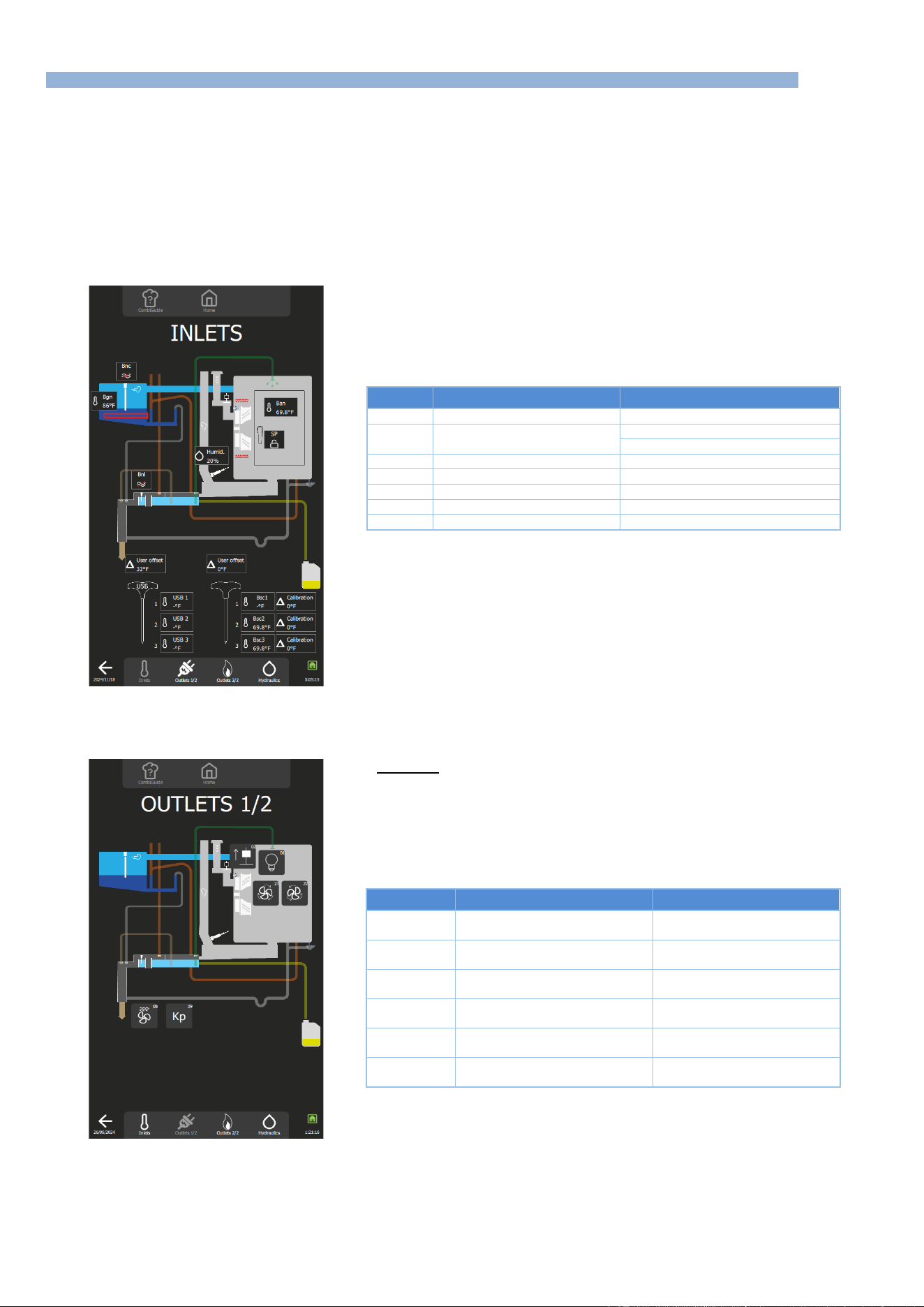
5 - TROUBLESHOOTING
CHEF’SCOMBI
Page 29 / 76
3VE490099EM – 10/25
5.3 MAINTENANCE SCREENS
After taking into account the information provided by the customer, and if no error message is displayed on the screen, activate the diagnostic help
module, which consists of 3 separate screens.
Help function checks the board's inputs and outputs, as well as the associated peripheral components:
- Screen 1 "Inlets Diagram" check inputs: temperatures, doors, water level, humidity, etc…
- Screen 2 "Outlets Diagram", comprising two screens, controls outputs: ventilation, heating, lighting, safety contactor, technical
ventilation, IN valve, etc.
- Screen 3 "Hydraulics diagram" controls hydraulics outputs: water solenoid valves, cleaning pump, drain pump, descaling pump...
You can navigate between the various diagrams using the display area at the bottom of the screen, accessible from any of the 4 screens of the
diagnostic assistance module.
5.3.1 INLETS STATUS SCREEN
Imputs
Normal status
Remarks
Ban
Cooking cavity temperature
-
Sp
Door position
Padlock closed = door closed
Padlock open = door open
Bnl
Cleaning box level
Red line through symbol = no water
Bnc
Steam generator water level
Red line through symbol = no water
Bgn
Steam generator temperature
-
Bsc1…3
Core probe temperature
-
Humid.
Humidity rate
-
5.3.2 OUTLETS STATUS SCREEN
This screen is divided into 2 screens: Outlets 1/2 and Outlets 2/2.
Screen 1/2
Pressing a button activates a timer, the duration of which may vary according to
the element being controlled. This time delay can be cancelled by pressing the
same button again.
No. Outlet
Components
Operating
01
Leds lighting
1 press on the button activates
the lighting for 60s
02
In flapper motor
1 press on the button activates
the flapper for 60s
08
Technical fan
1 press on the button activates
the fan for 5s
09
Safety contactor
1 press on the button activates
the contactor for 1s
22
Turbine (clockwise)
1 press on the button
activates the turbine for 5s
23
Turbine (counterclockwise)
1 press on the button
activates the turbine for 5s
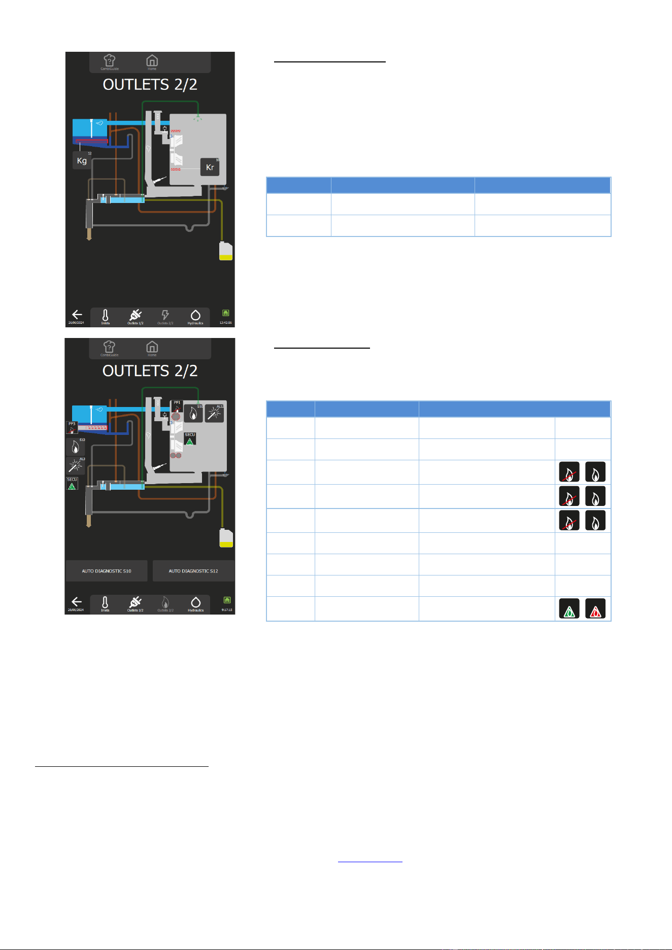
5 - TROUBLESHOOTING
CHEF’SCOMBI
Page 30 / 76
3VE490099EM – 10/25
Screen 2/2: Electric ovens
Pressing a button activates a timer, the duration of which may vary according to
the element being controlled. This time delay can be cancelled by pressing the
same button again.
No. Outlet
Components
Operating
10
Heating contactor
1 press on the button activates
the contactor for 1s
12
Steam generator contactor
1 press on the button
activates the contactor for 1s
Screen 2/2: Gas ovens
Pressing a button activates a timer, the duration of which may vary according to
the element being controlled. This time delay can be cancelled by pressing the
same button again.
No. Outlet
Components
Operating
AL12
Ignitor
1 press on the button, activates
the spark box for 5s
AL3
Steam generator spark
box
1 press on the key, activates
the spark box for 5s
PF1
Burner 1 flame present
Crossed out: flame absent
Not crossed out: flame present
PF2
Burner 2 flame present
Crossed out: flame absent
Not crossed out: flame present
PF3
Burner 3 flame present
Crossed out: flame absent
Not crossed out: flame present
S10
Outlet S10
1 press on the button activates
outlet for 10s
S11
Outlet S11
1 press on the button activates
outlet for 10s
S12
Outlet S12
1 press on the button activates
outlet for 10s
SECU
Safety
Green: not active Red: active
Procedure for checking the operation of the gas heater: presence of a flame in the burner (S10 - S11 or S12)
During the preventive maintenance visit, or in order to check the burners BEFORE removing them, you can use TWO TOOLS on this screen:
- The S10 / S11 / S12 burner buttons (number of burners depending on the model): Each button will attempt to ignite the burner, resulting in
correct ignition and flame detection (the corresponding PFx icon is no longer crossed out), or in a safety shutdown (the associated SECU
label changes to red).
- The « AUTO DIAGNOSTIC S10, S11 and S12 » buttons : These buttons are used to check that the gas burner fans are operating correctly
and then to make a real evaluation of the ignition quality. Even if ignition takes place, the quality will be assessed on 4 levels, from Fast
(perfect), to Problematic, to Medium and Difficult. Depending on the rating, it will not be necessary to remove the burner to check the
electrodes and burners.
Using the S10 / S11 / S12 burner buttons
» Press button S10 or S11 (depending on the model) or S12 (depending on the type of burner to be tested) to
activate the burner concerned.
For 10 seconds, outlets Ar-10 / Ar-11 or Ar-12 on the Main board closes, as well as outlets Ar-081 and Ar-09.
This causes the relay on the gas board to close, initiating an ignition cycle.
» If this fails, try again.
If the PF1 / PF2 or PF3 sticker is no longer crossed out, and the associated SECU sticker stays green, this
indicates that the system is operating correctly.
- Check the heating elements (spark box, gas board, etc.). (►Troubleshooting)
» If another failure occurs, make a third attempt.
If the PF1 / PF2 or PF3 sticker is crossed out, and the associated SECU sticker changes to red, this indicates
that the system isn’t operating correctly.
PF1
PF1
PF2
PF2
PF3
PF3
SECU
SECU
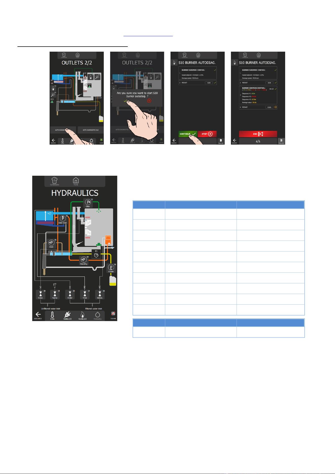
5 - TROUBLESHOOTING
CHEF’SCOMBI
Page 31 / 76
3VE490099EM – 10/25
- Dismantle the burner and clean and/or adjust the electrodes in accordance with the instructions in this
manual. (► Electrode inspection). (►Control of the electrodes)
Using the “S10 / S11 / S12 auto-diagnostic” buttons
In progress
» Pressing the AUTO DIAGNOSTIC button S10 or S11 (depending on the model) or S12 (depending on the type of
burner to be tested) activates the burner self-diagnosis module.
5.3.3 HYDRAULIC DIAGRAMS
Pressing a button activates a timer, the duration of which may vary according to
the element being controlled. This time delay can be cancelled by pressing the
same button again.
No. Outlet
Components
Operating
P - 13
Cleaning pump
1 press on the button activates
the pump for 5s
P - 06
Steam generator drain pump
1 press on the button activates
the pump for 5s
P - 05
Cleaning box drain pump
1 press on the button activates
the pump for 5s
P - 04
Descaling pump
1 press on the button activates
the pump for 5s
P - 03
Grease collection pump (optional)
1 press on the button
activates the pump for 5s
Ycond. - 18
Condenser solenoid valve
1 press on the button activates
the solenoid valve for 60s
Yspray - 15
Spray solenoid valve
1 press on the button activates
the solenoid valve for 60s
Ysteam
generator - 20
Steam steam generator solenoid
valve
1 press on the button activates
the solenoid valve for 60s
Ycool - 19
Cooling solenoid valve
1 press on the button activates
the solenoid valve for 60s
Ydescal. - 16
Descaling solenoid valve
1 press on the button activates
the solenoid valve for 60s
No. Inlet
Components
Operating
E1
Pressure switch Grease
collection (optional)
Normally closed, opens if there
is excess pressure in the circuit
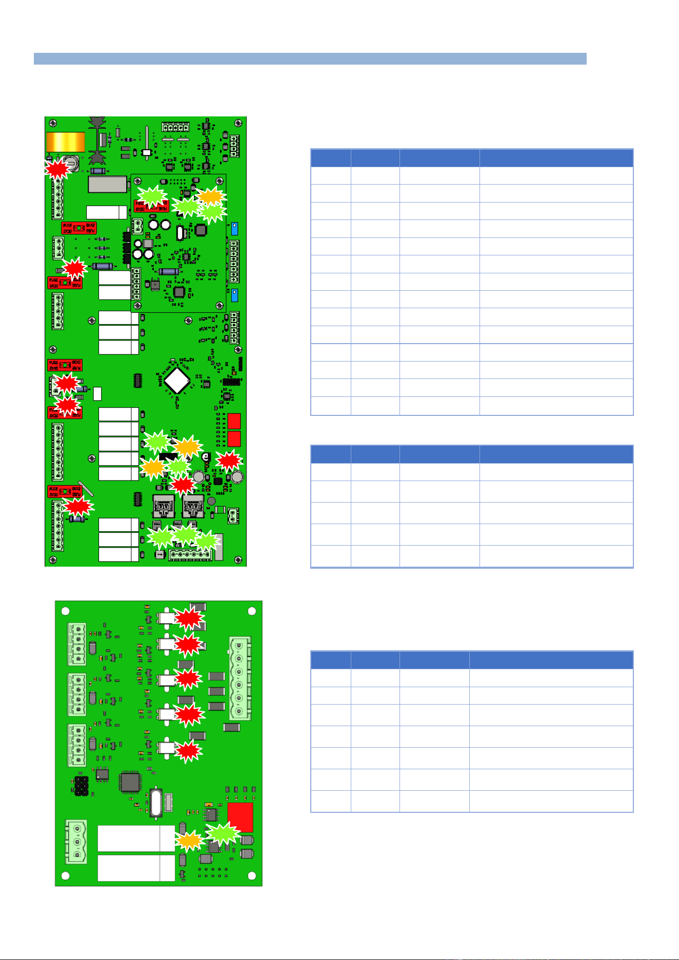
5 - TROUBLESHOOTING
CHEF’SCOMBI
Page 32 / 76
3VE490099EM – 10/25
5.4 COMMUNICATIONS LEDS
5.4.1 LEDS IDENTIFICATION
Main board, humidity board
Main board
LED
Colour
Status
Designation
100
Red
On - Permanent
3.3 Volt voltage present
101
Red
On - Permanent
5 Volt voltage present
400
Orange
Flashing
Tx signals RS485 communication
401
Green
Flashing
Tx signals RS485 communication
402
Orange
Flashing
Tx signals RS485 communication
403
Green
Flashing
Tx signals RS485 communication
600
Green
On - Permanent
Outlet S1 switched on
601
Green
On - Permanent
Outlet S2 switched on
602
Green
On - Permanent
Outlet S3 switched on
700
Red
On - Permanent
Fuse F2 OK
701
Red
On - Permanent
Fuse F3 OK
702
Red
On - Permanent
Fuse F4 OK
800
Red
On - Permanent
Fuse F1 OK
801
Red
On - Permanent
Lighting if actived Kp. Fuse Fm OK
*
Humidity board
LED
Colour
Status
Designation
100
Green
On - Permanent
Fuse F1 OK
200
Green
Flashing then Off
Indicates uncorrect operation of the
humidity sensor
201
Green
Flashing then
Permanent
Indicates correct operation of the
humidity sensor
400
Orange
Flashing
RS485 communication Tx signals -
Transmit
401
Green
Flashing
RS485 communication Rx signals -
Reception
Gas board
LED
Colour
Status
Designation
400
Orange
Flashing
Tx signals RS485 communication
401
Green
Flashing
Tx signals RS485 communication
500
Red
Permanent
Presence of gas in the gas steam
generator burner
501
Red
Permanent
Presence of gas in convection heater
burner 2 (on certain models only)
502
Red
Permanent
Presence of gas in convection heater
burner 1
503
Red
Permanent
Gas safety fault - steam generator
burner
504
Red
Permanent
Gas safety fault - convection heat
burner
403
801
800
100
700
701
401
400
100
101
702
602
600
601
201
401
400
504
503
500
501
502
402
400
401
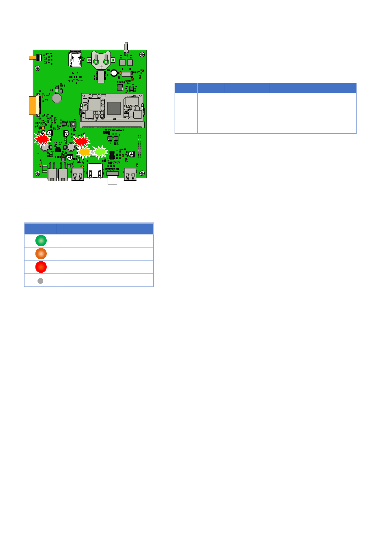
5 - TROUBLESHOOTING
CHEF’SCOMBI
Page 33 / 76
3VE490099EM – 10/25
Interface board
LED
Colour
Status
Designation
100
Red
On - Permanent
3.3 Volt voltage present
101
Red
On - Permanent
5 Volt voltage present
500
Orange
On - Permanent
Tx signals RS485 communication
501
Green
On - Permanent
Tx signals RS485 communication
5.4.2 OPERATION: COMMUNICATION
Legends
LED
Meaning
Green - Receiving
Orange - Transmitting
Red - Power on
LED off
501
500
100
101
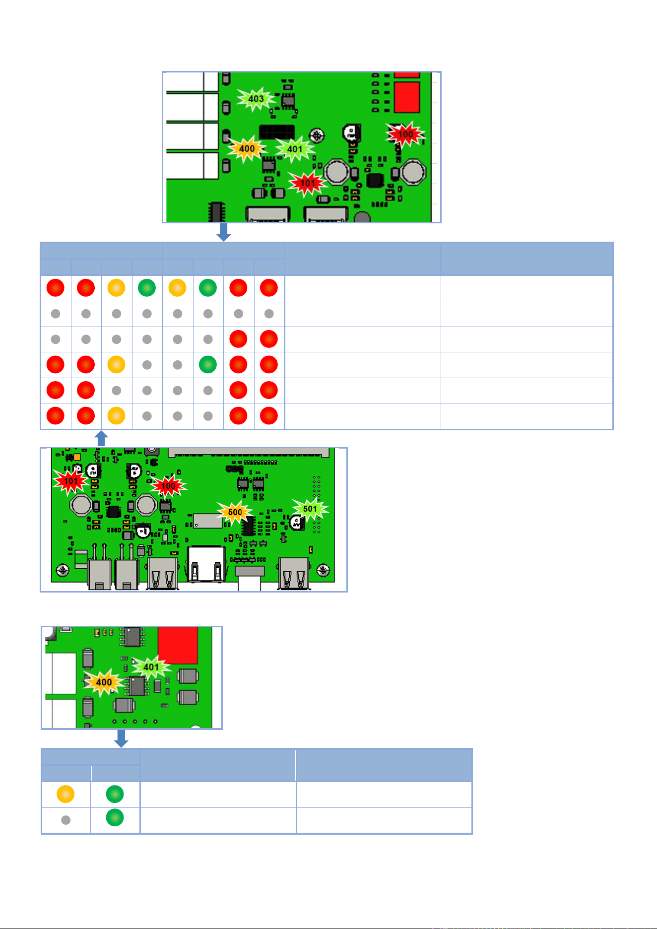
5 - TROUBLESHOOTING
CHEF’SCOMBI
Page 34 / 76
3VE490099EM – 10/25
Communication LEDs Main board and Interface board
Ai Interface Board
Aa Main board
Diagnostics
Solutions
101
100
500
501
400
401
101
100
Aa and Ai board - OK
Functioning normally
Power supply failure
Check for 24 Vd.c. at the terminals of J18
Connection problem with Ai board
Replace interconnecting cable between
Ar and Ai board, and/or Ai board
Aa board - Out of order
Replace the Aa board
Ai board - Out of order
Replace Ai board
Interconnecting Cable between Ai
board and Aa assembly faulty
Replace interconnecting cable
Communication LEDs Gas board
Gas board Aag
Diagnostics
Solutions
400
401
Aag board - OK
Functioning normally
Aag board - Out of order
Replace the board
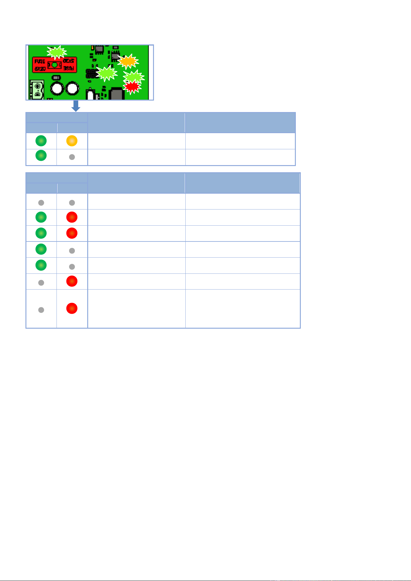
5 - TROUBLESHOOTING
CHEF’SCOMBI
Page 35 / 76
3VE490099EM – 10/25
Communication LEDs Humidity board
Humidity board Ahu
Diagnostics
Solutions
401
400
Ahu board - OK
Functioning normally
Ahu board - Out of order
Replace the board
Humidity board Ahu
Diagnostics
Comments
201
201
Standby
Initialization
Flashes - Start-up or wake-up from
standby.
Start-up calibration
Alternating flashes.
Initial heating ramp on heater
Blinking proportional to heating percentage.
Heater temperature within control
range
Normal functioning.
Heater overheating
Flashing.
Other errors
- Ar communication error
- CJ125 calibration error
- Supply voltage too low
- Humidity sensor missing or incorrectly
connected
- Heater probe current zero.
400
401
100
201
200

5 - TROUBLESHOOTING
CHEF’SCOMBI
Page 36 / 76
3VE490099EM – 10/25
5.5 OTHER SYMPTOMS
All electrical measurements must be carried out in compliance with local legislation (personnel authorization, use of PPE, etc.).
OFF-VOLTAGE tests must absolutely be carried out in this configuration. Make sure you carry out these tests safely (consignment, etc.).
SYMPTOM
CAUSE
WHAT TO DO?
The oven is not working the display is off.
- Supply voltage is not present at the device terminals.
Check condition of the power cable and all the connection points, and rectify any problems
encountered.
- Oven circuit breaker is not switched on.
Switch circuit breaker on or have it switched on. If it trips again, verify appliance is properly
insulated; leakage currents must be less than 30mA.
- System voltage is not present at the Ar Main board terminals.
Check voltage at terminals 1 and 2 of connector J18 (refer to the electronic diagram in this
manual). If there is no voltage, disconnect connector J18:
- If voltage is present again, replace the Main board,
- If voltage is still absent, check the Tc power supply. Verify Its correct operation is
indicated by a green LED; if necessary, replace power supply.
- Molex connector link cable between Main board and the screen is faulty.
Verify voltage is present. Check communication LEDs (see LED assignment section in this
document). If the problem persists, replace the cable.
- Screen is faulty.
If the problem persists, replace the screen.
- Short-circuit at switching power supply output.
LEDs (switching power supply, red LEDs on the Main board) are flashing. Disconnect cable
between the interface board and encoder board.
- Encoder inoperative, LED ring does not light up.
Verify it is correctly connected and operating correctly. If problem persists, replace encoder
board.
Screen inoperable, system won't start, random malfunctions, difficulty updating.
- Loss of communication.
Refer to the "screen inoperable or blocked" flowchart in this manual.
Display on, oven not working.
- An error code displayed (blocking message).
Refer to error code section of this manual.
- The oven door is not closed properly.
Make sure oven door is correctly locked.
- The switch does not detect when the oven is closed.
Check status of the door closing position switch in the technical panel, if the output remains at "0":
On the Aar Main board, verify J5 connector is correctly connected to its socket, verify contact
closes when the door is closed and that it is correctly fitted mechanically. If the problem
persists, adjust the door and replace the switch if necessary.
The screen is lit, the oven works but the lighting does not.
- LED banners are not powered.
Refer to "Enclosure lighting fault" flow chart in this document.
The screen is lit, the oven, lighting and ventilation are working, but it does not heat up or does not reach the set temperature.
Special case of electric ovens
- One or more heating elements do not work.
Refer to "electric heater fault" diagram in this document.
Special case of gas ovens
Burner does not ignite.
- Spark box does not work.
Refer to "gas spark box fault" diagram in this document.
- Gas fan not working.
Check fan power supply at terminal 2 of Kbg or Kbr and Xb.
- if 230Va.c. present, change the fan.
- if there is no 230Vac, verify Kbg or Kbr contactor is switched on, check the connections
and tighten the screws, etc.
- No gas or too low pressure.
Verify gas entering the appliance is of the correct type and pressure.
- The gas valve does not work.
Check the resistance of the 848 Sigma gas solenoid valve coils Ev1 (terminals 4-3) and Ev2
(terminals 1-3);
- If the resistance is greater than 0, check the gas pressure at the valve inlet and the
burner heating demand; if the burner does not ignite, replace the valve,
- If the resistance is equal to 0, replace the valve.
- The ionisation electrode does not detect the flame.
Check electrode (see electrode adjustment section of this manual).
- The flame control box does not work.
Turn off the gas supply and start cooking, if at the end of the ignition sequence:
- "gas error" fault appears, the flame control box is operational, proceed with the above
checks.
- if the error does not appear, replace the flame control box.
Noisy burner.
- The gas settings are incorrect or the wrong gas is being connected.
Check in the technician parameters that the gas selected corresponds to what is indicated on
the oven identification plate.
Check gas supplied to the oven is the same as that indicated on the oven identification plate.
5 - TROUBLESHOOTING
CHEF’SCOMBI
Page 37 / 76
3VE490099EM – 10/25
SYMPTOM
CAUSE
WHAT TO DO?
Noisy burner.
- Gas valve incorrectly set.
Check CO2 level by following the procedure indicated in the manual.
- Air supply problem.
Check that the air inlet tube is correctly connected and that it is not obstructed.
- The silicone venturi valve connection tube is disconnected or faulty.
Check that the tube is correctly connected. If the problem persists, replace it.
Explosion on starting gas burner.
- The ignition electrode is incorrectly adjusted.
Check the electrode settings: insulation of the wires in relation to ground (stray sparks), check
that the electrode soapstone is not broken See "Checking the electrodes" section.
Polluting burner.
- The gas settings are incorrect or the wrong gas is being connected.
Check in technician parameters that gas selected corresponds to what is indicated on the
oven identification plate.
Check gas supplied to the oven is the same as what is indicated on the oven identification
plate.
- Gas valve incorrectly set.
Check CO2 level by following the procedure indicated in the manual.
Burner fan running at full speed.
- Communication fault between the Main board and the gas valve.
Check status of LEDs on gas board.
- If they are off, verify the gas board is connected to the Main board (rear connector,
condition of connections) and the gas board mounting screws are secure to the Main
board.
- If they are lit, check the various connections (screwing and fixing the connectors to their
sockets) from gas board to the fan.
The burner emits a random whistling sound.
- When the oven is cold, a hissing sound may be heard.
This should disappear quickly as the burner heats up.
- If the problem persists.
Check air intakes (unobstructed vents).
The spark box works continuously.
The Presence Flame (PF) does not return.
Fault in the connection between gas box and the gas board, verify wires and connections are
secure.
Fault in the connection between the gas board and Main board, check state of the LEDs on
gas board, verify rear connection between the gas board and Main board, verify the gas board
screws and connections are secure to the Main board, if the problem persists, replace the gas
board.
The pump whistles.
- Air in the circuit.
Check the circuit for leaks (connections, hoses, etc.).
- Defective bearings.
Verify the flow rate is as specified in this manual.
5 - TROUBLESHOOTING
CHEF’SCOMBI
Page 38 / 76
3VE490099EM – 10/25
5.6 FLOWCHART
5.6.1 SCREEN INOPERATIVE OR BLOCKED
The appliance has these
malfunctions:
- The system does not start,
- Random malfunctions,
- Difficulties in updating,
- Interface board crash,
- Screen inoperative...
Stop the oven using the
encoder, then restart it. While
the data is being loaded, press
the RESET key and then the
RESTART key.
Using the LED chapter
document, check the status
of the communication LEDs
and, if necessary, replace
the faulty board.
Is the screen
usable?
Stop the oven using the
encoder, then restart it. While
the data is being loaded, press
the RESET key and then the
REBOOT key.
Stop the oven using the
encoder, then restart it. While
the data is being loaded, press
the RESET key and then the
RESET DEFAULT SETTING
key.
Has the problem
been solved?
Has the problem
been solved?
Has the problem
been solved?
YES
NO
NO
NO
NO
REBOOT: Stops the
appliance and saves the
user interface (►Reset).
RESET DEFAULT SETTING:
Overwrites current settings
and user profiles (►Reset
).
RESTART: Hot oven restart
with user interface
preserved (►Reset).
5 - TROUBLESHOOTING
CHEF’SCOMBI
Page 39 / 76
3VE490099EM – 10/25
5.6.2 LIGHTING FAULT OF COOKING CAVITY
The door LEDs do not light up.
After checking that the door is closed,
From the maintenance menu, press the
lighting icon.
Locate the Ta
switching power
supply using the
electrical circuit board
diagram and the
voltage presence LED.
Disconnect the
LED strip from the
lighting terminal
box
LED 600 on the
Ar board lights
up.
Press the lightning icon
+
Using a multimeter
placed between S110
and Ta(-), check for the
presence of voltage.
Using a multimeter,
check the voltage
between L and N.
Power supply
LED on.
The power
supply LED
lights up again.
A voltage of
230Va.c.
appears.
A voltage of
24Vd.c. appears.
Check the
230Vac supply
line (connections,
wiring, protection,
etc.).
YES
NO
YES
NO
NO
NO
Disconnect
connector
J12.
NO
Find the
causes of
the short
circuit.
YES
Power off,
replace power
supply.
YES
After checking
the
connections,
replace the
defective cover.
Check fuse F5 and, if
necessary, replace it
after eliminating the
cause of its failure.
YES
LED 600 on the
Ar board lights
up
Replace the
LED Strip
Replace
the Main
Board Ar
YES
NO
5 - TROUBLESHOOTING
CHEF’SCOMBI
Page 40 / 76
3VE490099EM – 10/25
5.6.3 ELECTRIC HEATER FAULT
The electric oven does not heat up.
From the maintenance menu, activate the
operation of the contactors: Kp, Kg steam
heater and Kr convection heater.
On the Ar board, verify
connector J16 is
correctly connected and
that the wires are
correctly connected to
the terminals.
Keep the contactor
engaged
+
Place a measuring
device between
terminals 2/4-2/6-4/6.
The contactor(s)
close(s) for 3 sec.
Oven off, replace the
heating element.
Oven off, replace the
contactor.
The connector is
in place and the
connections are
secure.
The device
indicates the
nameplate
voltage.
A voltage of
230Vac appears
on the multimeter
screen.
A voltage of
230Vac appears
on the multimeter
display.
Replace the Ar board.
NO
YES
YES
NO
NO
NO
Connect the measuring
device to terminals 1/3-
1/5-3/5 of the contactor.
NO
If check the fuses and/or
the oven power supply.
YES
Hold the contactor
control + Place the
multimeter on terminals
A1 and A2 of the
controlled contactor.
YES
Place a measuring device
between terminals S12/S11/S10
depending on the type of oven
and the cooking mode selected
in N230Va.c. and select Kr or Kg
from the maintenance menu.
Reconnect and/or
ensure that the
connector is correctly.
YES
The device
indicates the
nameplate
voltage.
Verify connections and
condition of the wiring
between the Ar board
and the controlled
contactor.
NO
YES
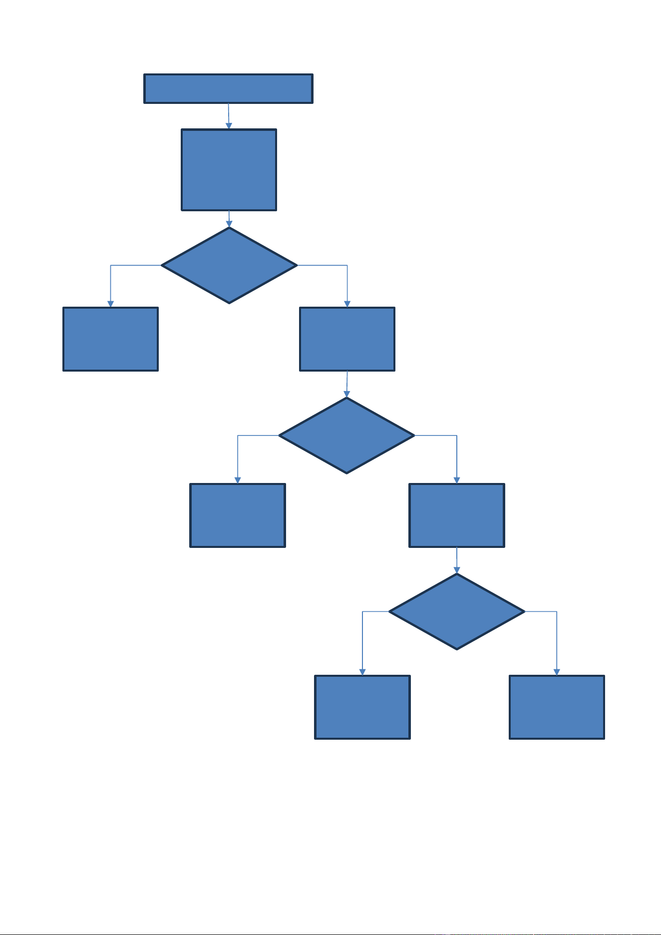
5 - TROUBLESHOOTING
CHEF’SCOMBI
Page 41 / 76
3VE490099EM – 10/25
5.6.4 GAS SPARK BOX FAULT
On the Aag board, place
a multimeter between
Xb and J7-2 (Al12) or
J7-3(Al3)
+ Activate output Al12 or
Al3 on the Aag board.
Spark box OK.
A spark occurs at
the spark box
outlet.
Replace defective
spark box.
Presence of
230Va.c. at the
output of Al12 or
Al3.
Presence of
230Va.c. at the
input of the Aag
board
On the Aag board, place
the multimeter between
Xb and J7-1.
NO
YES
YES
Find the cause of the
short circuit.
Replace the Aag board.
NO
YES
NO
Verify spark box working properly
Remove approx. 1 cm of
the ignition electrode
wire + From the
maintenance menu,
activate output Al12
(convection heat) or Al3
(steam generator
heating).
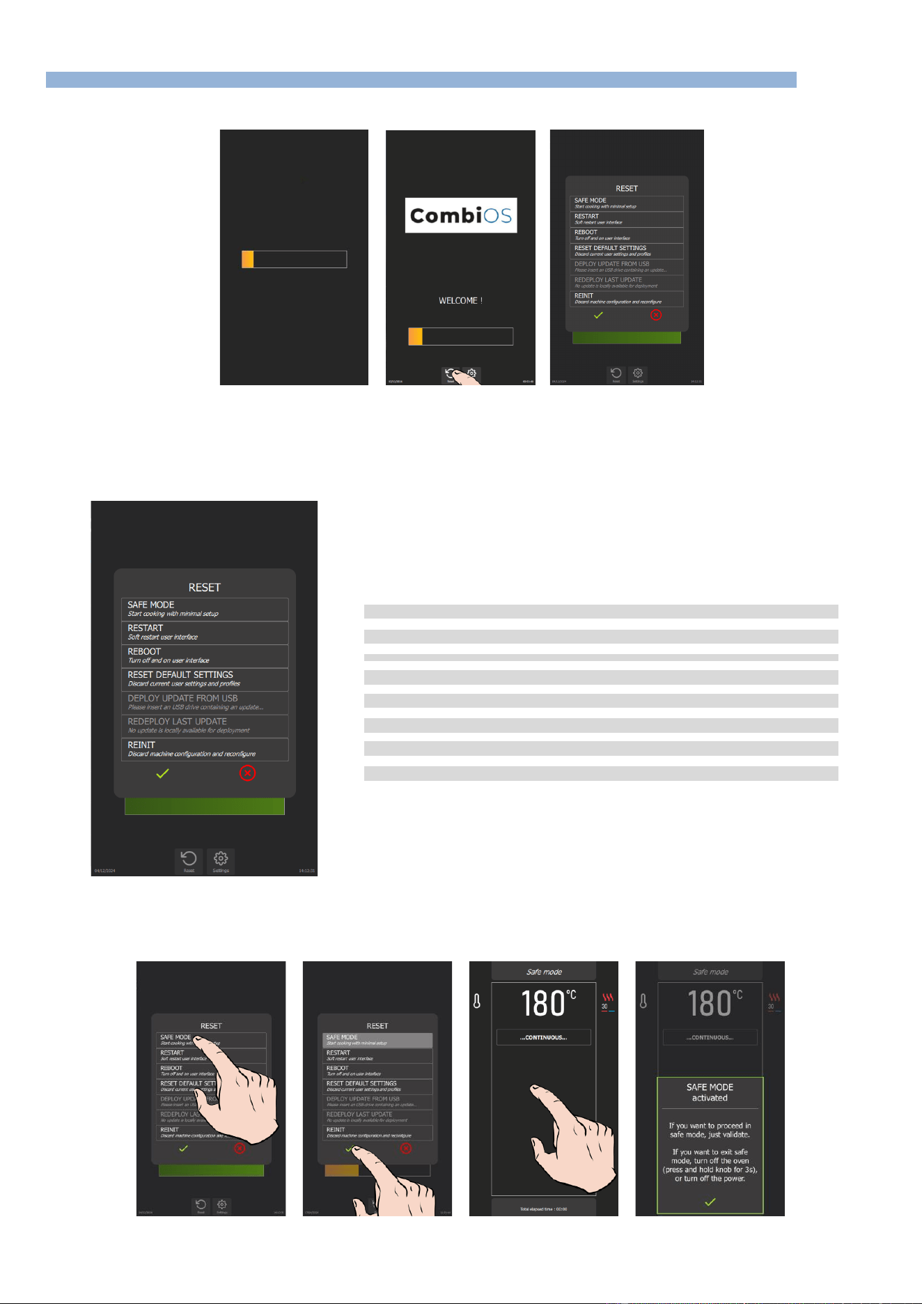
5 - TROUBLESHOOTING
CHEF’SCOMBI
Page 42 / 76
3VE490099EM – 10/25
5.7 RESET
5.7.1 ACCESS TO THE RESET SCREEN
» Switch on the display by holding down the encoder button until the power-on bar graph is displayed.
» Wait for the "Home" menu to appear.
» Press "Reset" button.
The display shows a pop-up of possible actions.
5.7.2 PARAMETERS LIST
➔
Switch Chef’sCombi to Safe Mode
➔
Restart Interface
➔
Restart interface and Main board
➔
Reset to default settings
➔
Reinstall an update from a USB key
➔
Reinstall last update
➔
Reset Chef’sCombi configuration (accessible with factory PIN code only)
➔
Validate or cancel selected "Reset" type
Safe mode
This action enables you to go into safe mode with minimal configuration. Only the ambient temperature: the default temperature is 356°F, and the
cooking mode: convection heat cooking mode are indicated.
5 - TROUBLESHOOTING
CHEF’SCOMBI
Page 43 / 76
3VE490099EM – 10/25
On confirmation, the continuous icon appears on the display, indicating cooking similar to the continuous cooking mode. When the screen is pressed,
an information message appears, indicating the following:
"SAFE MODE ACTIVATED
If you want to procees in safe
mode, just validate.
If you want to exit safe mode,
turn off the oven (press and
hold knob for 3 seconds), or
turn off the power.
✓
"
In the event of a problem with the screen, this mode can be obtained by successively opening the door 3 times within 5 seconds at power-up.
Restart: Restart the interface
This option performs a basic restart of the Chef'sCombi interface. No customer-configured parameters are affected.
Reboot: Restart with reset
This function restarts the unit and exits the current cycle. No customer-configured parameters are affected.
Reset default settings
This function resets current settings and user profiles. Access to this action is protected by a PIN code (level 5 or 7), guaranteeing the security of the
process (►Settings – PIN Codes).
In particular, it deletes parameters, profiles, customer protocols, manufacturer protocols and customer photos.
After a reset, it is necessary to redo the CO control and "Steam generator calibration".
WARNING! Please inform the customer!
All parameters configured and copied by the customer, such as settings, profiles, protocols
(recipes), photos, etc… will be deleted.
Deploy update from USB : Reinstall an update from a USB stick
This feature is active when a USB key is connected to the appliance. It allows you to reinstall (force) an update from a USB key.
When a manufacturer update is in progress, there is no need to activate this menu. If the update version
on the USB key is higher than the one already present in the chef’sCombi memory, the update starts
automatically (►Settings - Updating the software).
Redeploy last update : Reinstall the last update
This menu allows you to reinstall the latest update installed on the appliance. It is essential to select this option when corrupted parameters have been
installed or detected by the appliance. A clean backup is kept on the SD card.
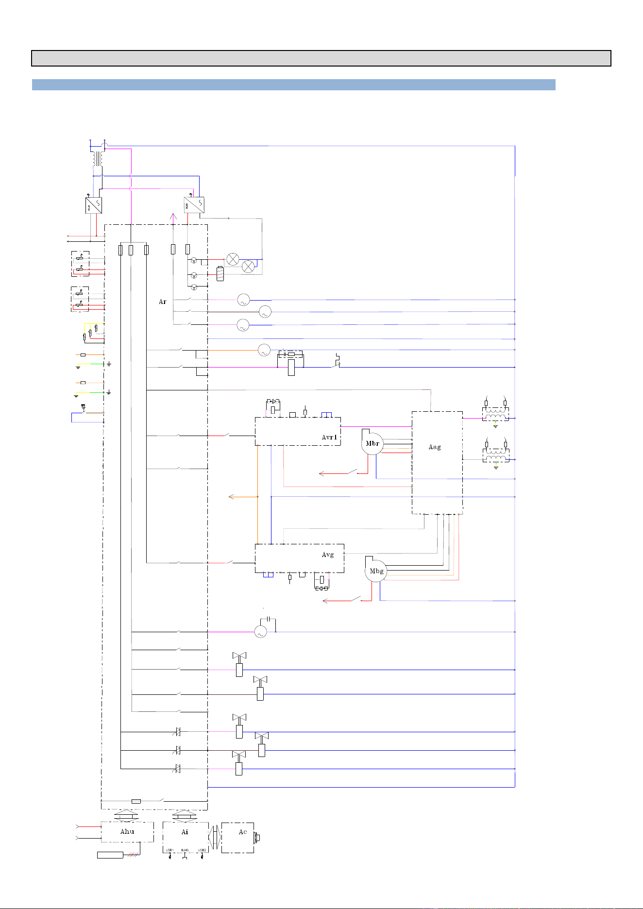
6 - ELECTRIC DIAGRAMS
CHEF’SCOMBI
Page 44 / 76
3VE490099EM – 10/25
6. ELECTRIC DIAGRAMS
6.1 DIAGRAMS
6.1.1 GAS OVENS
Wiring diagram
F1
0,2A
F2
3,15A
F3
3,15A
230 VAC
0 Vsys
+24 Vsys
Ban
Baa
Ba
Bgn
01
110
°C
°C
°C
Bg
°C
Bga
24V dc
LL
NN
PEPE
Tc
L
N
PE
+
-
03
02
Lo
X(-)
35 W
Kp
3 4
10
PF1
S1-
S1P
S1H
S1+
14
Black
White
Orange
Red
PF2
S2-
S2P
S2H
S2+
Xvb
Kbr
1 2
Secu 12
230Vac
11
10
12
Kp
5 6
10
3
7 6
5
11
12
14
Black
White
Orange
Red
Spark
Flame
8
9
Zbg
A1
A2
Kbg
Xvb
Kbg
1 2
7
6
5
12
Spark
Flame
8
9
Zvb
Kbr
A2
A1
N
3
4
11
07
4
Ar-081
13
Mpn
Cpn
15
Yspray
Bsc (3xPT100)
230 VAC
24 VAC
F4
3,15A
F5
4A
+24 VDC
24V dc
Ee1
Ee2
Xe-B
Xe-G
05
04
06
Mdg
Mvm
Mvg
09
091
Nbt
08
Mt1
081
17
16
Ydescal.
Ycool
18
Ycond.
N
Bsc 1
Bsc C
Bsc 2
Bsc 3
Bnl
Niveau d'eau boite de lavage
cleaning box water Level
Bnc
Niveau eau générateur vapeur
steam generator water Level
E1
Entrée libre / free Input
E2
Entrée libre / free Input
Sp
Sp
Sp
14
PF3
S3-
S3P
S3H
S3+
Secu 3
Al-3
Eag
Ebg
Ear
Ebr
AL-12
Fvb-S
Ta
75 W
M
M
M
M
Fm
Kp
Zp
M
Yboiler
19
20
Xa
Xb
La
0 Vsys
+24 Vsys
Ahu
Eclairage cavité / cavity Lighting
Electroaimant Clapet In / Air Inlet Valve Electromagnet
Pompe détartrage / descaling Pump
Pompe vidange mouffle / drain cavity Pump
Pompe vidange gén&érateur / drain generator Pump
Connexion neutre / neutral Connection
Ventilation technique / technical Fan
Contacteur de puissance / power Contactor
Allumeur Chauffe convection
Commande EV gaz Chauffe convection
Moteur brûleur Chauffe convection
Allumeur Chauffe génértateur vapeur
Commande EV gaz Chauffe générateur vapeur
gas SV for steam generator Heating Control box
Moteur brûleur Chauffe generateur vapeur
steam generator Heating burner Motor
gas SV for convection Heating Control box
steam generator Heating Spark box
convection Heating burner Motor
convection Heating Spark box
Pompe lavage / cleaning Pump
EV douchette / spray hose SV
EV dissolution poudre / descaling powder SV
EV condenseur / condenser SV
EV refroidissement / cooling SV
EV générateur vapeur / steam generator SV
Connexion neutre / neutral Connection
Shu
+24Vsys
+
-
0Vsys
G:\R&D\P roj ets NT N PD Dossi er s\P N PD FM 21 NXG GLO B AL CO MB I\ Readi ness Serv ic es\S chém as électriques_Electrical diagrams\Capture 1.PNG
Ar
Er1
Sr1
F6-6.3A
Contact porte / door contact
Sonde à coeur / core Probe
Sonde temperature generateur
generator temperature Probe
Sonde température ambiante
Ambient temperature Probe
électroniques
electronic boards
Alimentation servitudes
utilities Supply
Filtre CEM / EMC Filter
Etat de cuisson en cours / cooking in progress Statut
Contact libre de potentiel / free potential Contact
Alimentation cartes
Supply
Cavity lighting
Descaling pump
Drain cavity pump
Drain generator pump
Technical fan
Power contactor
Allumeur chauffe
convection
Commande EV gaz
chauffe convection
Moteur brûleur -
chauffe convection
Allumeur - générateur
vapeur
Commande EV gaz -
générateur vapeur
Moteur brûleur -
générateur vapeur
Cleaning pump
Spray hose SV
Descaling powder SV
Condenser SV
Cooling SV
Steam generator SV
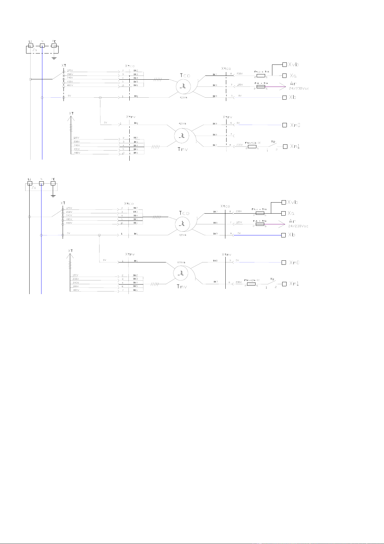
6 - ELECTRIC DIAGRAMS
CHEF’SCOMBI
Page 45 / 76
3VE490099EM – 10/25
Power diagram 6 & 10 GN 1/1
Control transformer
Cavity fan motor
transformer
Power diagram 6 & 10 GN 2/1
Control transformer
Cavity fan motor
transformer
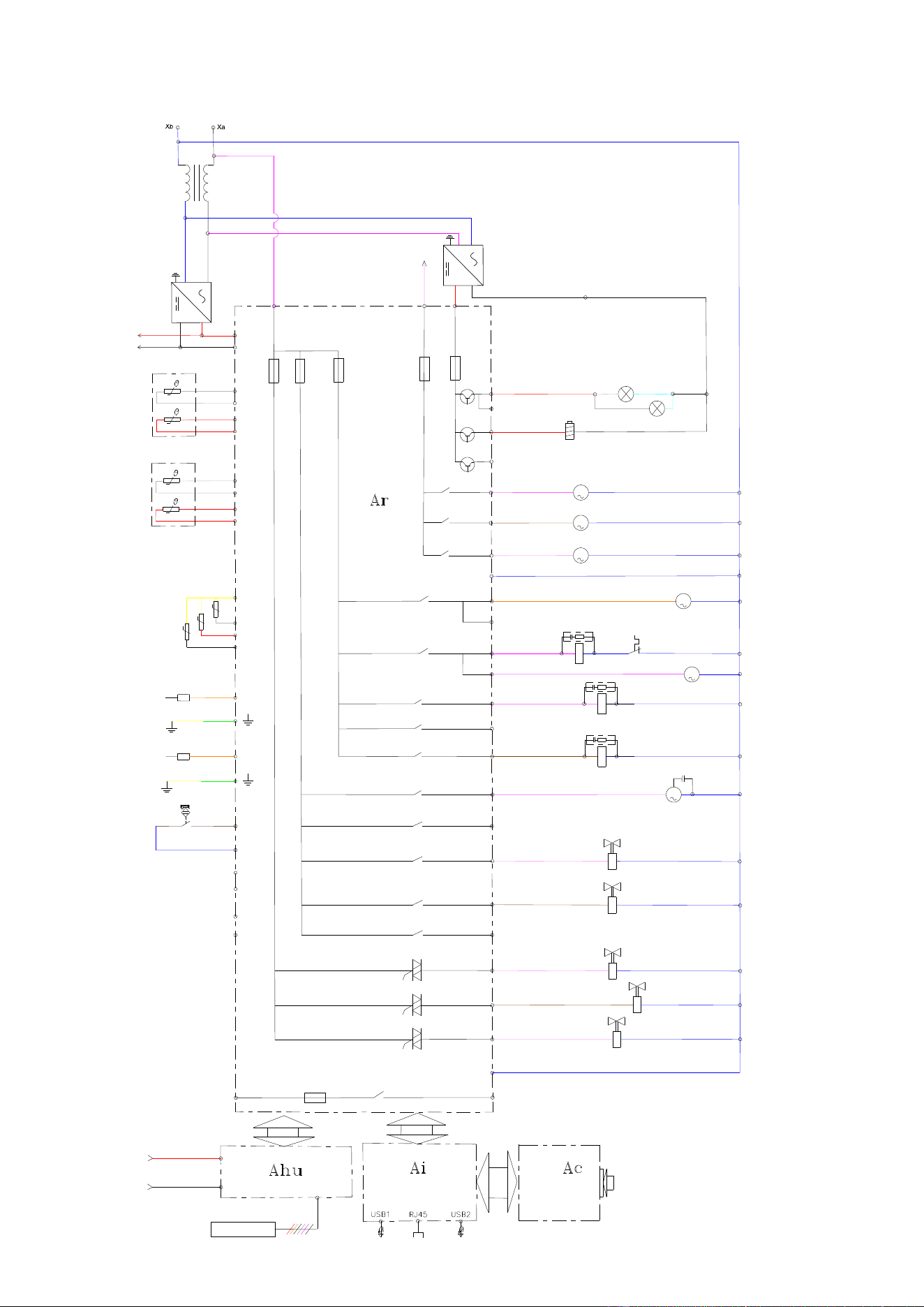
6 - ELECTRIC DIAGRAMS
CHEF’SCOMBI
Page 46 / 76
3VE490099EM – 10/25
6.1.2 ELECTRIC OVENS
Wiring diagram
F5
4A
F4
3.15A
F1
0,2A
F2
3,15A
F3
3.15A
Ban
Baa
Ba
Bgn
01
110
Bsc 1
Bsc (3xPT100)
Bsc Com
Bsc 2
Bsc 3
Bnl
Niveau d'eau boite lavage
°C
°C
°C
Bg
°C
Bga
03
02
Lo
water Level cleaning box
Ee1
Ee2
Xla-G
Xla-B
Bnc
Niveau d'eau générateur vapeur
water Level steam generator
Sp
Sp
Sp
E1
Entrée libre / free Input
E2
Entrée libre / free Input
05
04
06
Mdg
M
Mvm
M
Mvg
M
Nbt
08
081
M
Mt1
09
091
Fm
Kp
Zp
10
11
12
Zr
Kr
Zg
Kg
13
M
Mpn
Cpn
16
Ydescal.
17
15
Yspray
19
Ycool
18
Ycond.
20 Yboiler
N
14
M
Mt2
+24 VDC
230 VAC
230 VAC
0 Vsys
+24 Vsys
24 VAC
X(-)
24V dc
Ta
+
-
75 W
24V dc
Tc
L
N
PE
+
-
35 W
PE
N
L
La
Fvb-s
120 V
+24 Vsys
0 Vsys
Ahu
Eclairage cavité / cavity Lighting
Electroaimant Clapet In / Air inlet valve Electromagnet
Pompe détartrage / descaling Pump
Pompe vidange mouffle / drain cavity Pump
Pompe vidange générateur / drain generator Pump
Connexion neutre / neutral Connection
Ventilation technique / technical Fan
Contacteur de puissance / power Contactor
Ventilation technique / technical Fan
Chauffe convection / convection Heating
Chauffe générateur vapeur / steam generator Heating
Pompe de lavage / cleaning Pump
Réserve / Reserved
EV douchette / spray hose SV
EV dissolution poudre / descaling powder SV
Réserve / Reserved
EV condenseur / condenser SV
EV refroidissement / cooling SV
EV générateur vapeur / steam generator SV
Connexion neutre / neutral Connection
G:\R&D\Projets NT NPD D ossiers\P NPD FM21 NXG GLOBAL COMBI\Readi ness Servi ces\Schém as électriques_Electrical diagrams\Capture 1.PNG
Ar
Shu
+
-
+24Vsys
0Vsys
Etat de cuisson en cours / cooking in progress Statut
(Contact libre de potentiel / free potential Contact)
Er1
Sr1
F6-6.3A
Contact porte / door Contact
Sonde à coeur / core Probe
Sonde temp. générateur vapeur
steam generator temperat. Probe
Sonde température ambiante
Ambient temperature Probe
EMC Filter
électroniques
electronic boards
Alimentation servitudes
Utilities supply
Alimentation cartes
Supply
Filtre CEM
Cavity lighting
Air inlet valve
Electromagnet
Descaling pump
Drain cavity pump
Drain generator
pump
Technical fan
Power contactor
Technical fan
Convection heating
Steam generator
heating
Cleaningh pump
Spray hose SV
Descaling powder SV
Condenser SV
Cooling SV
Steam generator SV
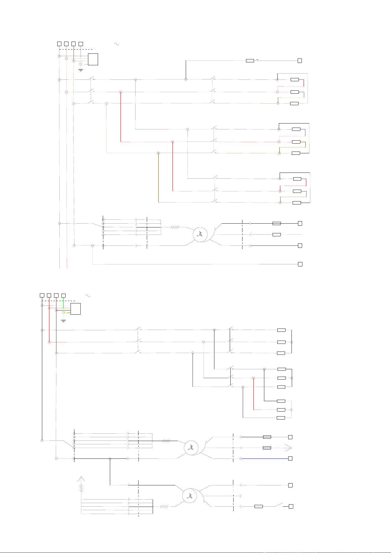
6 - ELECTRIC DIAGRAMS
CHEF’SCOMBI
Page 47 / 76
3VE490099EM – 10/25
Power diagram 6GN1/1 – 208V – 240V
Xa
Kr1
1
2
3
4
5
6
Za
Rc1
Kp
1
2
3
4
5
6
Xa
Xb
Ftco - T4A
e s
Xm0
Ar
Fvb - T4A
e s
24/230Vac
Tco
230V
415VA
0V
120V
Xtco
Xtco
240V
480V
0V
400V
XT
120V
208V
2
1
3
4
5
10
8
7
6
Xm1
Ftmv-10A CC
e s
208V/240V 3
Kg1
1
2
3
4
5
6
Rg1-1
Kg2
1
2
3
4
5
6
Rg1-2
BK2
BK3
BK4
BK5
BK6
BK1
BK7
BK8
BK9
Heating element
Immersion heaters
Control transfromer
Power diagram 6GN1/1 – 480V
Heating element
Immersion heater
Control transformer
Cavity fan motor
transformer
3
4
5
10
1
0V
Xtmv
240V
480V
0V
400V
XT
120V
208V
XT
415VA
0V
6
Xm0
Kp
13
14
Ftmv-10A CC
e
s
230V
8
Xtmv
7
Xa
L3
L1
L2
PE
480V 3
Za
Xa
Xb
Ftco - T4A
e s
Ar
Fvb - T4A
e s
24/230Vac
Tco
230V
415VA
0V
120V
Xtco
Xtco
2
1
3
4
5
10
8
7
6
Tmv
Xm1
240V
480V
400V
120V
208V
2
Kp
1
2
3
4
5
6
Kr1
1
2
3
4
5
6
Rc1
Kg1
1
2
3
4
5
6
Rg1-1
Rg1-2
BK2
BK3
BK4
BK5
BK6
BK1
BK1
BK2
BK3
BK4
BK5
BK6
BK7
BK8
BK9
BK8
BK7
BK9
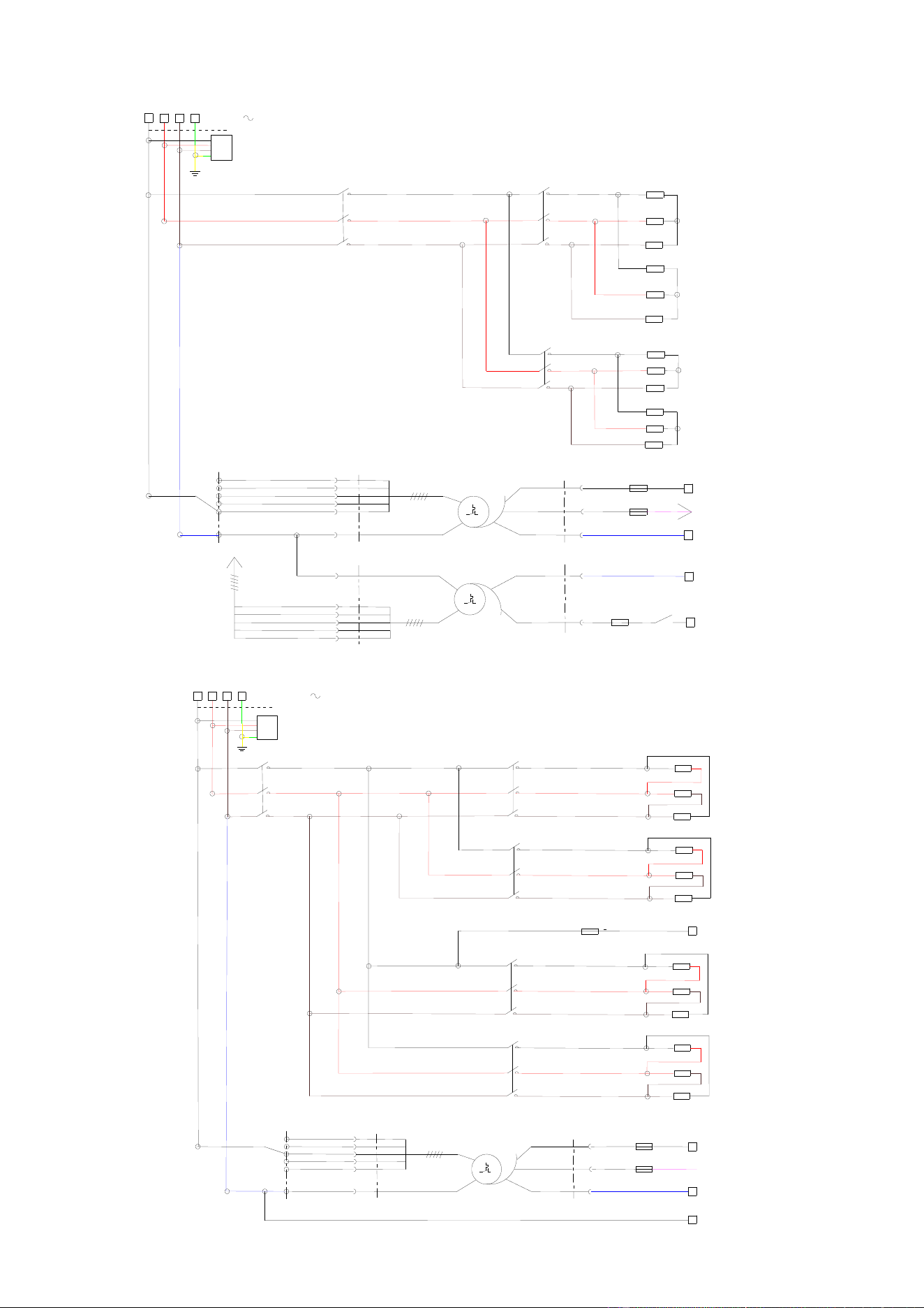
6 - ELECTRIC DIAGRAMS
CHEF’SCOMBI
Page 48 / 76
3VE490099EM – 10/25
Power diagram 6GN2/1 – 480V
240V
480V
400V
120V
208V
2
3
4
8
7
1
0V
Xtmv
240V
480V
0V
400V
XT
120V
208V
XT
828VA
0V
5
Xm0
Kp
13
14
Ftmv-10A CC
e s
230V
6
Xtmv
Xa
L3
L1
L2
PE
Za
480V 3
Kp
1
2
3
4
5
6
Kr1
1
2
3
4
5
6
Rc1-1
Rc1-2
Kg1
1
2
3
4
5
6
Rg1-1
Rg1-2
Xa
Xb
Ftco - T4A
e
s
Ar
Fvb - T4A
e
s
24/230Vac
Tco
230V
415VA
0V
120V
Xtco
Xtco
2
1
3
4
5
10
8
7
6
Tmv
Xm1
BK2
BK3
BK4
BK5
BK6
BK1
BK7
BK8
BK9
BK1
BK2
BK3
BK4
BK5
BK6
BK8
BK7
Heating elements
TImmersion heaters
Control transformer
Cavity fan motor
transformer
Power diagram 6GN2/1 and 10GN1/1 – 208V- 240V
Kg2
1
2
3
4
5
6
Rg1-2
Xm1
Ftmv-10A CC
e s
Xa
Xb
Ftco - T4A
e s
Xm0
Ar
Fvb - T4A
e s
24/230Vac
Tco
230V
415VA
0V
120V
Xtco
Xtco
240V
480V
0V
400V
XT
120V
208V
2
1
3
4
5
10
8
7
6
Xa
L3
L1
L2
208 / 240V 3
Kr1
1
2
3
4
5
6
PE
Za
Rc1-1
Kg1
1
2
3
4
5
6
Rg1-1
Kp
1
2
3
4
5
6
Kr2
1
2
3
4
5
6
Rc1-2
BK2
BK3
BK4
BK5
BK6
BK1
BK7
BK8
BK9
Heating element
Immersion heater
Heating element
Immersion heater
Control transformer
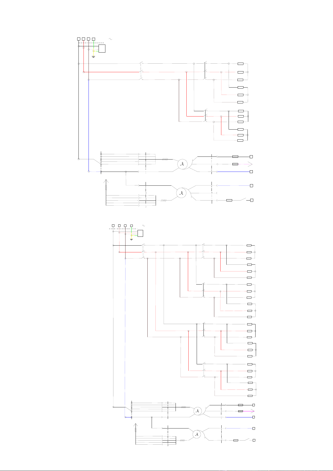
6 - ELECTRIC DIAGRAMS
CHEF’SCOMBI
Page 49 / 76
3VE490099EM – 10/25
Power diagram 10GN1/1 – 480V
Heating elements
Immersion heaters
Control transformer
Cavity fan motor
transformer
Power diagram 10GN2/1 – 480V
Heating elements
Immersion heaters
Heating elements
Immersion heaters
Control transformer
Cavity fan motor
transformer
BK7
BK8
BK9
BK9
BK8
BK7
Xa
L3
L1
L2
PE
Za
480V 3
Xa
Xb
Ftco - T4A
e s
Ar
Fvb - T4A
e s
24/230Vac
Tco
230V
415VA
0V
120V
Xtco
Xtco
2
1
3
4
5
10
8
7
6
Tmv
Xm1
240V
480V
400V
120V
208V
2
3
4
5
10
1
0V
Xtmv
240V
480V
0V
400V
XT
120V
208V
XT
415VA
0V
6
Xm0
Kp
13
14
Ftmv-10A CC
e
s
230V
8
Xtmv
7
Kp
1
2
3
4
5
6
Kr1
1
2
3
4
5
6
Rc1-1
Rc1-2
Kg1
1
2
3
4
5
6
Rg1-1
Rg1-2
BK2
BK3
BK4
BK5
BK6
BK1
BK1
BK2
BK3
BK4
BK5
BK6
BK1
BK2
BK3
BK4
BK5
BK6
BK8
BK7
Kg2
1
2
3
4
5
6
L3
L1
L2
Kr1
1
2
3
4
5
6
Kg1
1
2
3
4
5
6
Rc1-1
Rc1-2
Xa
Rg1-1
Rg1-2
Kr2
1
2
3
4
5
6
Rc2-1
Rc2-2
Rg2-1
Rg2-2
Kp
1
2
3
4
5
6
PE
480V 3
Za
Xa
Xb
Ftco - T4A
e
s
Ar
Fvb - T4A
e
s
24/230Vac
Tco
230V
415VA
0V
120V
Xtco
Xtco
2
1
3
4
5
10
W7
W8
W9
Tmv
Xm1
240V
480V
400V
120V
208V
2
3
4
8
7
1
0V
Xtmv
240V
480V
0V
400V
XT
120V
208V
XT
828VA
0V
5
Xm0
Kp
13
14
Ftmv-10A CC
e s
230V
6
Xtmv
BK2
BK3
BK4
BK5
BK6
BK1
BK7
BK8
BK9
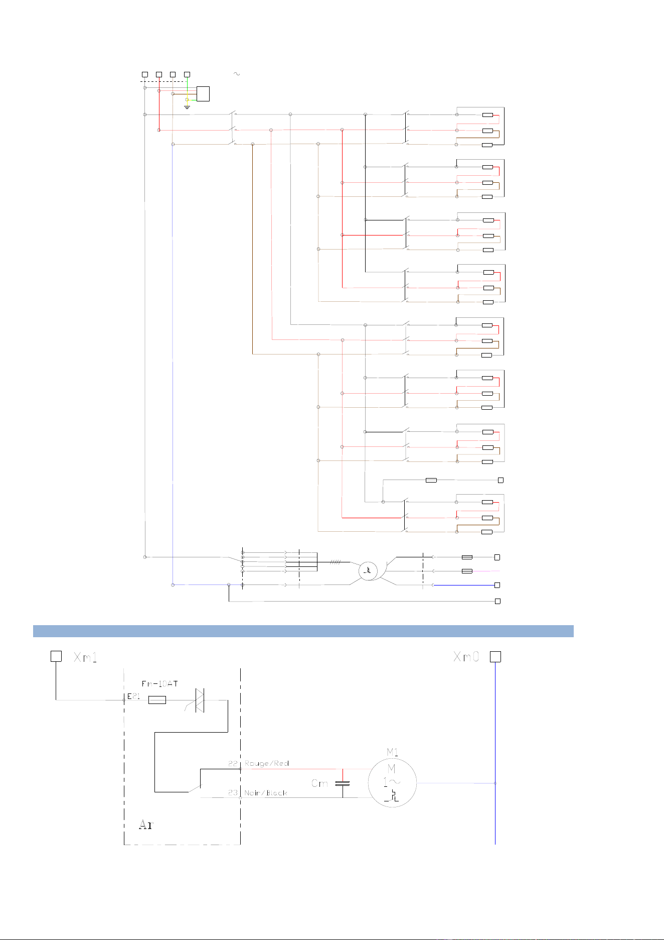
6 - ELECTRIC DIAGRAMS
CHEF’SCOMBI
Page 50 / 76
3VE490099EM – 10/25
Power diagram 10GN2/1 – 208V- 240V
Xa
PE
L3
L1
L2
Za
Rc2-2
Xa
Xb
Ftco - T4A
e s
Xm0
Ar
Fvb - T4A
e s
24/230Vac
Tco
230V
415VA
0V
120V
Xtco
Xtco
240V
480V
0V
400V
XT
120V
208V
2
1
3
4
5
10
8
7
6
Kp
1
2
3
4
5
6
208V/240V 3
Kr1
1
2
3
4
5
6
Kg1
1
2
3
4
5
6
Rc1-1
Rg1-1
Kg2
1
2
3
4
5
6
Kr2
1
2
3
4
5
6
Rg1-2
Rc1-2
Kr3
1
2
3
4
5
6
Rc2-1
Kg3
1
2
3
4
5
6
Rg2-1
Kg4
1
2
3
4
5
6
Rg2-2
Kr4
1
2
3
4
5
6
Ftmv-10A CC
e s
Xm1
BK2
BK3
BK4
BK5
BK6
BK1
BK7
BK8
BK9
Heating element
Immersion heater
Immersion heater
Heating element
Heating element
Immersion heater
Immersion heater
Heating element
Control transformer
6.2 6 AND 10 LEVEL CAVITY VENTILATION
Cavity fan motor
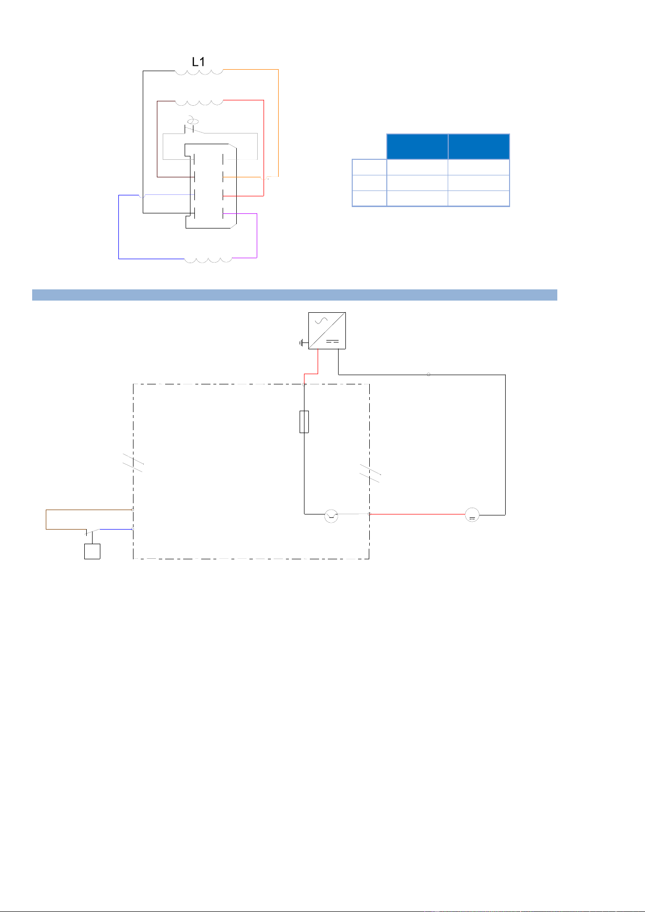
6 - ELECTRIC DIAGRAMS
CHEF’SCOMBI
Page 51 / 76
3VE490099EM – 10/25
4
8
3
2
1
5
6
7
Black
Purple
Red
Blue
Brown
Orange
White
White
L3
L2
L1
L2
L3
Half size
Motor
Full size
Motor
56 O
56 O
56 O
20.4 O
20.4 O
20.4 O
Values tolerence +/-15%
Half size
motor
Full size
motor
L1
56
20.4
L2
56
20.4
L3
56
20.4
Values tolerances +/-15%
6.3 GREASE COLLECTION OPTION
Switching power supply
Grease pump
Pressure SwitchControls
valve opening/ Blocked
Circuit
F5
4A
+24 Vdc
03
M
option
collection de
graisse
Collection
grease option
24V dc
PEPE
++
--
L
NN
MPG
Tc 75W
X(-)
E1
P
Pressostat Contrôle
ouverture Vanne / circuit
Ar
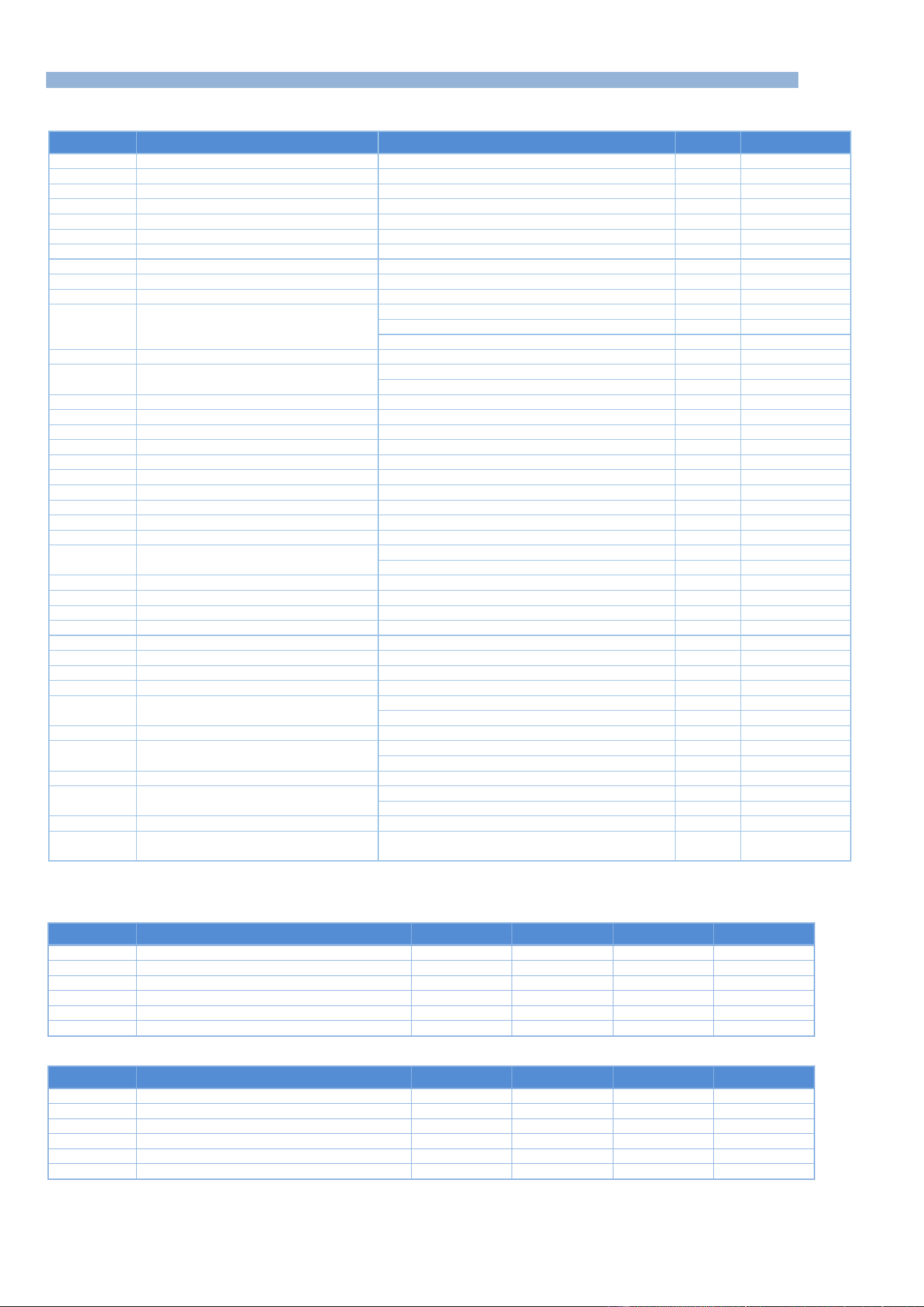
6 - ELECTRIC DIAGRAMS
CHEF’SCOMBI
Page 52 / 76
3VE490099EM – 10/25
6.4 PARTS LIST
Common components
Ref.
Designation
Characteristics
Quantity
Code
Ac
Encoder board
1
309716
Ahu
Additional humidity board
1
309718
Ai
Interface board
1
309714
Ar+Ahu
Main + humidity boards
Electric oven
1
309720
Connection cable for Main – interface boards
1
309723
Ar+Ahu+Aag
Main + humidity + gas boards
Gas oven
1
309721
Ba
Ambient probe
PT100
1
159030
Bg
Steam generator temperature probe
PT100
1
159028
Bnc
Steam generator level probe
1
301514
Bnl
Cleaning box level probe
1
301519
Bsc
Core probe
3-point probe - 6- level GN 1/1 ovens
1
301517
3-point probe - 10-level GN 2/1 ovens
1
301518
Probe 3 points - 6 levels GN2/1 & 10 levels GN1/1
1
301524
Cpn
Cleaning pump condensator
6.3µF
1
304311
Cm
Cavity motor condensator
12,5µF - GN1/1 oven
1
304296
25µF - GN2/1 oven
1
304326
Ee1 - Ee2
LED strips
24Vd.c. 5W
1
309719
F1
Fast fuse
5x20 - 0,2 A
1
300787
F2 - F3 - F4
Time-delay fuses
5x20 - 3,15A
3
309407
F5
Standard automotive fuse
ATC - 4A
1
300807
Fm
Motor fuse
5x20 - 10A
1
300788
Ftco
Fuse holder and fuse
4A T
1
300777 + 300801
Ftmv
Fuse holder and fuse
10A CC
1
300792 + 300793
Fvb
Fuse holder and fuse
4A T
1
300777 + 300801
La
EMC filter
1
309639
Lo
Electromagnet of In flapper
24Vd.c. 8,3W
1
468108
M1
Cavity fan motor
6 and 10 levels GN1/1
1
147147
6 and 10 levels GN2/1
1
159032
Mdg
Descaling pump motor
56W - Steam generator
1
304321
Mpg
Grease pump motor
24Vdc 31W
1
304314
Mpn
Cleaning pump motor
253W
1
314396
Mt1 – Mt2
Technical ventilation motor
1
304334
Mvg
Steam generator drain motor
56W
1
304323
Mvm
Cavity fan motor
56W
1
304322
P
Pressure switch
159064
Shu
Humidity sensor
1
301515
Sp
Closed door reed switch
Standard door
1
300806
Reversed door option (left-hand fitting)
1
300805
Ta
Switching power supply
230Va.c. / 24Vd.c.
1
300802
Tc
Switching power supply
230Va.c. / 24Vd.c.
1
308353
230Va.c. / 24Vd.c. if grease collection option
1
300802
Tco
Control transformer
415VA
1
408407
Tcm
Cavity fan motor transformer
6 and 10 levels GN1/1
1
408407
6 and 10 levels GN2/1
1
408406
Yspray - Ycond
Two-way solenoid valve
Spray / Condenser
1
468105
Ycool - Yboiler
- Ydescal.
Three-way solenoid valve
Descaling / Steam generator / Injection
1
468107
Contactors Electric ovens
208V/240V - 230V
Ref.
Designation
6 GN1/1
6 GN2/1
10 GN1/1
10 GN2/1
Kg
Steam generator contactor
300699 * 2
300699 * 2
300699 * 2
300699 * 4
Zg
Interference-suppression Blocks
300769 * 2
300769 * 2
300769 * 2
300769 * 4
Kp
Power contactor
300699
300702
300702
300798
Zp
Interference-suppression Blocks
300769
407002
407002
300799
Kr
Regulation contactor ( convection heater)
300699
300699 * 2
300699 * 2
300699 * 4
Zr
Interference-suppression Blocks
300769
300769 * 2
300769 * 2
300769 * 4
480V
Ref.
Designation
6 GN1/1
6 GN2/1
10 GN1/1
10 GN2/1
Kg
Steam generator contactor
300697
300698
300698
300698 * 2
Zg
Interference-suppression Blocks
300769
300769
300769
300769 * 2
Kp
Power contactor
300697
300699
300698
300702
Zp
Interference-suppression Blocks
300769
300769
300769
407002
Kr
Regulation contactor ( convection heater)
300697
300699
300698
300699 * 2
Zr
Interference-suppression Blocks
300769
300769
300769
300769 * 2
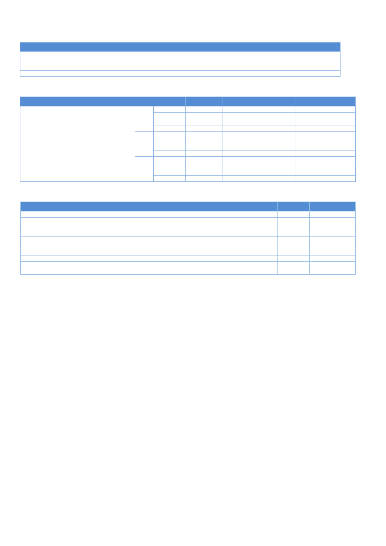
6 - ELECTRIC DIAGRAMS
CHEF’SCOMBI
Page 53 / 76
3VE490099EM – 10/25
Contactors Gas ovens
Ref.
Designation
6 GN1/1
6 GN2/1
10 GN1/1
10 GN2/1
Kbg
Steam generator burner contactor
300697
300697
300697
300697
Kbr
Burner regulation switch
300697
300697
300697
300697
Kp
Power contactor
300697
300697
300697
300697
Zp - Zvb - Zbg
Interference suppressor
300769
300769
300769
300769
Heating elements Electric oven
Ref.
Designation
6 GN1/1
6 GN2/1
10 GN1/1
10 GN2/1
Rc
Convection heating elements
208V
Codes
159010
159012
159013
159012+159014
Vulcan codes
00-978295
00-978296
00-978308
00-978296+00-978298
240V
Codes
159005
159007
159008
159007+159009
Vulcan codes
00-978291
00-978292
00-978293
00-978292+00-978294
480V
Codes
159015
159017
159018
159017+159019
Vulcan codes
00-978299
00-978300
00-978301
00-978300+00-978302
Rg
Steam generator immersion
208V
Codes
159024
159025
159025
159025 * 2
heaters
Vulcan codes
00-978305
00-978306
00-978306
00-978306 * 2
240V
Codes
159022
159023
159023
159023 * 2
Vulcan codes
00-978303
00-978304
00-978304
00-978304 * 2
480V
Codes
159026
159027
159027
159027 * 2
Vulcan codes
00-978305
00-978308
00-978308
00-978308 * 2
Specific components - Gas ovens
Ref.
Designation
Characteristics
Quantity
Code
Aag
Additional gas board
1
309721
Avg
Steam generator gas solenoid valves
1
310356
Avr1
Gas solenoid valves regulation 1
1
310356
Eag
Steam generator gas spark box
prim:230Va.c. 0,3A /sec 1x15kV
1
408402
Ear
Gas spark box for convection heaters 1/2
prim:230Va.c. 0,3A /sec 1x15kV
1 or 2
408402
Ebg - Ebr
Curved ignition electrode
2
148885
Straight ionisation electrode
2
148886
Flamme
Flame control electrode
2
148889
Mbg
Steam generator burner motor
207VA
1
159046
Mbr
Burner motor regulation
207VA
1
159046
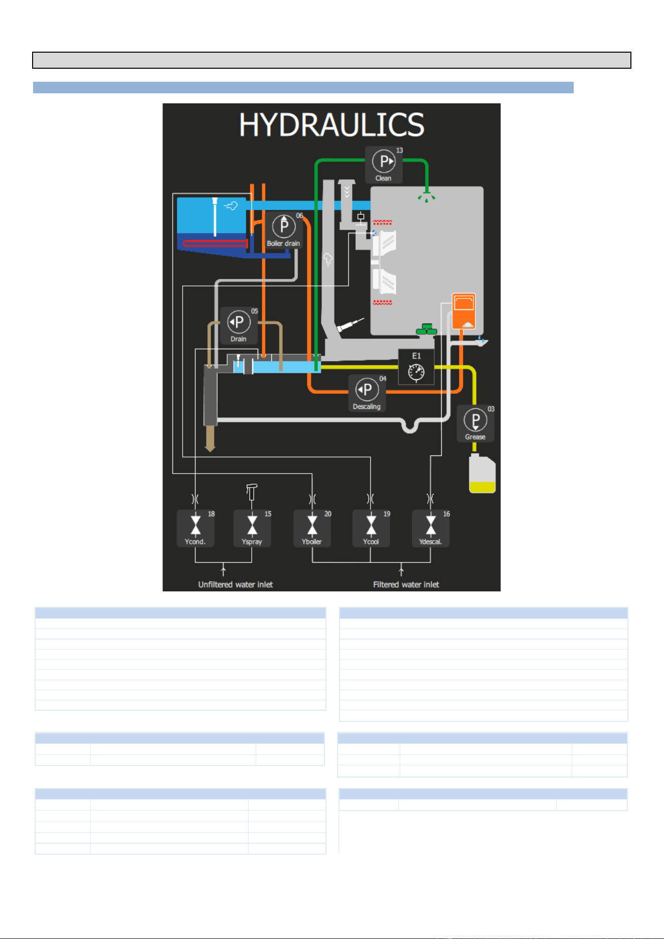
7 - HYDRAULIC DIAGRAM
CHEF’SCOMBI
Page 54 / 76
3VE490099EM – 10/25
7. HYDRAULIC DIAGRAM
7.1 6 AND 10 LEVEL OVENS
UNFILTERED WATER (hard water inlet)
FILTERED WATER (Soft water inlet)
Pressure (Min / Max)
14.5 psi / 87psi (1.5 bar / 6 bar)
Pressure (Min / Max)
14.5 psi / 87psi (1.5 bar / 6 bar)
Max cold water temperature
73°F
Max cold water temperature
73°F
Nature
Filtered at 114 mesh
Nature
Filtered at 114 mesh
Water quality
Chloride Cl-: ≤ 8.76 gr/gal (150 ppm)
Hardness
3.5 to 11.6 grains/gal (60 to 200 ppm)
Chlorine Cl2: ≤ 0.01 gr/gal (0.2 ppm)
Water quality
Chloride Cl-: ≤ 8.76 gr/gal (150 ppm)
6.5 ≤ PH ≤ 9
Chlorine Cl2: ≤ 0.01 gr/gal (0.2 ppm)
Conductivity
≥ 25 TDS
6.5 ≤ PH ≤ 9
Connection
Male G 3/4" + GHT 3/4" adapter
Conductivity
≥ 25 TDS
Max. instantaneous consumption
3.35 gpm
Connection
Male G 3/4" + GHT 3/4" adapter
Max. instantaneous consumption
2.03 gpm
TWO-WAY SOLENOID VALVE - COLD WATER
THREE-WAY SOLENOID VALVE - COLD WATER
Ycond
Condenser solenoid valve
42,8 gal/h
Yboiler
Solenoid valve for steam generator filling
87.1 gal/h
Yspray
Solenoid valve for spray hose
158,5 gal/h
Ycool
Cooling solenoid valve
14.4 gal/h
Ydescal.
Descaling solenoid valve
14.4 gal/h
PUMPS
PRESSURE SWITCH (GREASE COLLECTION OPTION)
P - 04
Clean
2061 gal/h
E1
Pressure switch
0.3 bars
P - 03
Descaling
317 gal/h
P - 13
Drain
317 gal/h
P - 05
Drain steam generator
317 gal/h
P - 06
Grease
52,31 gal/h
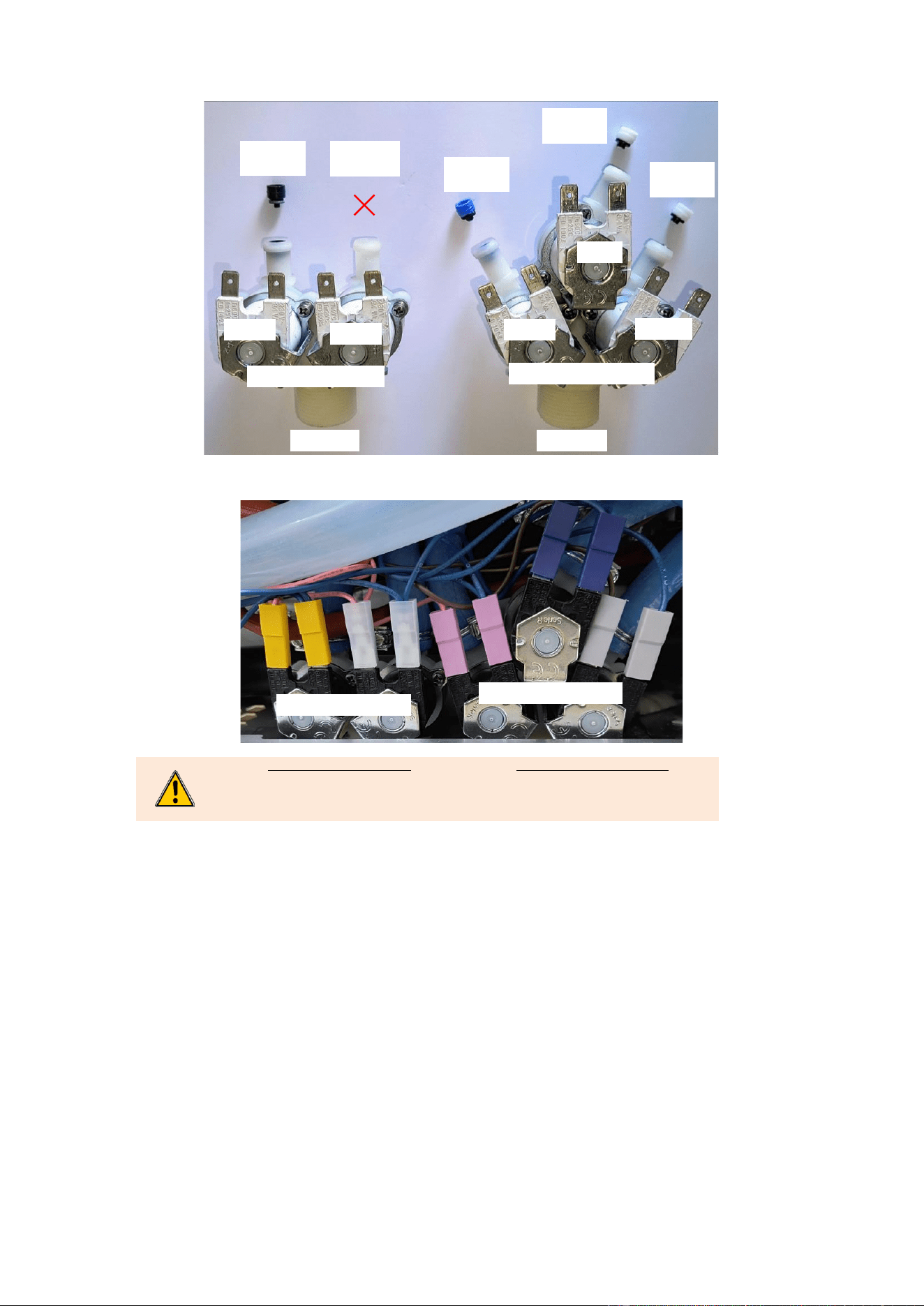
7 - HYDRAULIC DIAGRAM
CHEF’SCOMBI
Page 55 / 76
3VE490099EM – 10/25
7.1.1 FLOW LIMITER
7.1.2 IDENTIFICATION OF TERMINALS
Two-way Solenoid valve
Condenser → Yellow
Spray hose → Clear - Transparent
Three-way Solenoid valve
Cooling → Blue
Steam generator → Pink - purple
Descaling → Grey
Two-way Solenoid valve
Three-way Solenoid valve
Three-way Solenoid valve
Two-way Solenoid valve
Black
42,8 gal/h
Blue
87.1 gal/h
White
14.4 gal/h
White
14.4 gal/h
-
158,5 gal/h
158,5 gal/h
158,5 gal/h
Ycond.
Yspray
Yboiler
Ycool
Ydescal.
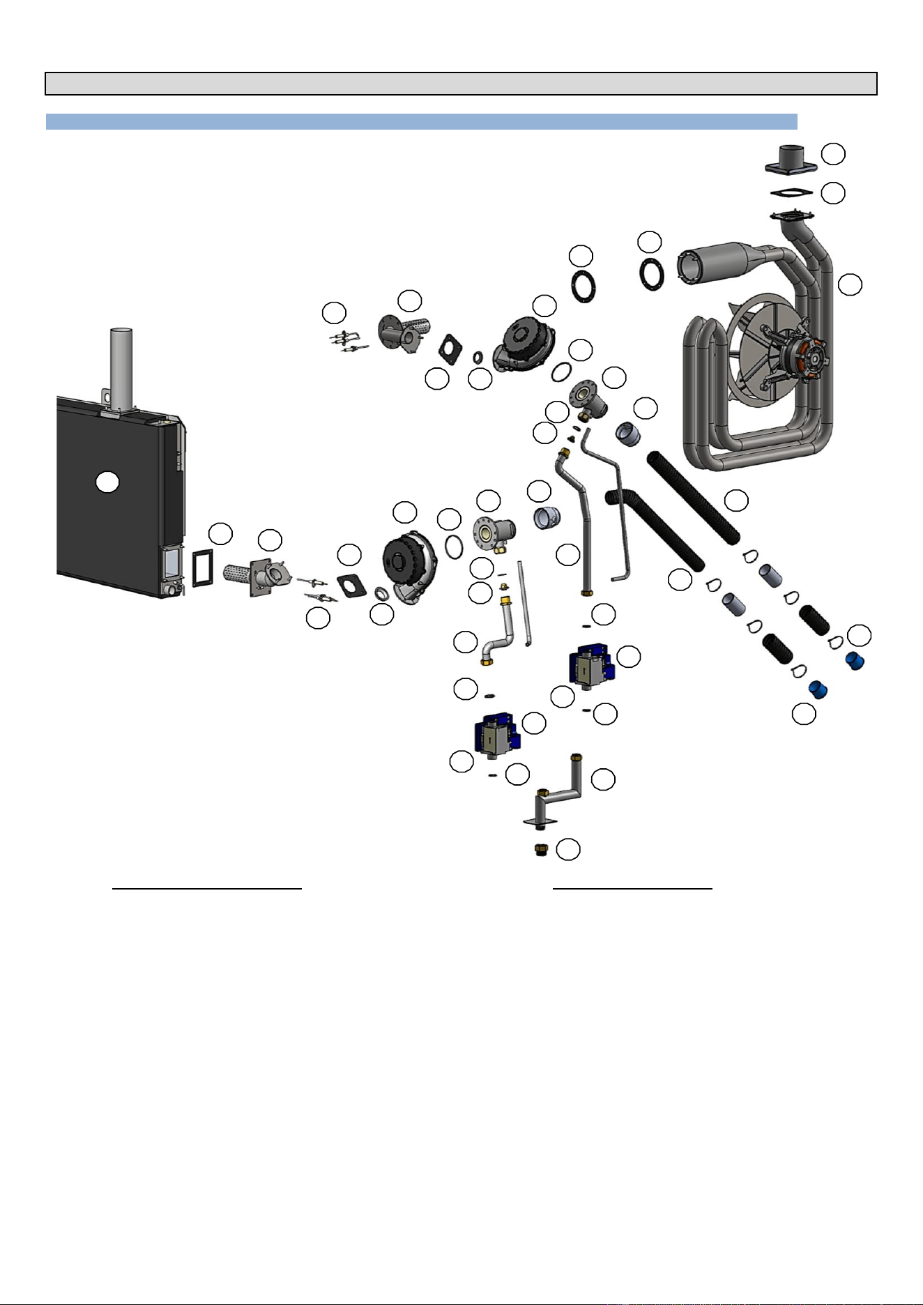
8 - GAS DIAGRAM
CHEF’SCOMBI
Page 56 / 76
3VE490099EM – 10/25
8. GAS DIAGRAM
8.1 6 AND 10 LEVEL OVENS
Gas circuit - Convection heating
1
Heat exchanger
2
Gas exchanger outlet gasket
3
Flue gas pipe
4
Gas exchanger inlet gasket
5
Gas burner
6
Ignition electrodes
7
Gas burner gasket
8
Gas burner reducer
9
Gas burner blower
10
Gas venturi seal
11
Venturi
12
Gasket 20/27
13
Injector (present depending on model)
14
Gas pipework
15
Gas valve
16
Safety box
17
Venturi adapter
18
Air inlet hose
19
Flexible air plug
20
Gas ramp
21
3/4" NPT gas inlet adaptor
Gas circuit - Steam heating
50
Gas steam generator
51
Steam generator inlet gasket
52
Gas burner
53
Ignition electrodes
54
Gas fan gasket
55
Gas burner reducer
56
Gas burner blower
57
Gas venturi seal
58
Venturi
59
Gasket 20/27
60
Injector (present depending on model)
61
Gas pipework
62
Gas valve
63
Safety box
64
Venturi adapter
65
Air inlet hose
66
Flexible air plug
2
3
4
7
10
59
9
15
1
20
14
13
21
5
8
16
50
11
6
12
60
2
51
52
53
54
55
56
18
57
59
59
62
61
58
4
12
12
17
19
63
66
65
64
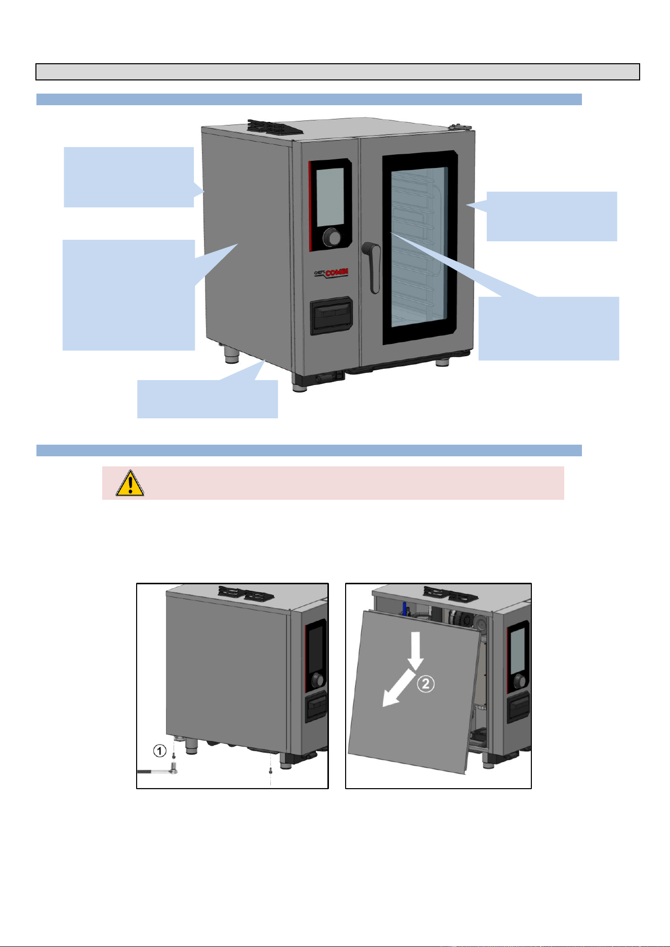
9 - ACCESS TO COMPONENTS
CHEF’SCOMBI
Page 57 / 76
3VE490099EM – 10/25
9. ACCESS TO COMPONENTS
9.1 LOCATION OF TECHNICAL COMPONENTS
9.2 ACCESS TO COMPONENTS
CAUTION: The appliance must be disconnected from its power supply during cleaning or
maintenance, and when replacing parts.
The various assembly procedures and component access below are designed to avoid any repetition which could lead to errors when improving the
procedures.
Actions already explained in a paragraph are not re-explained but are referred to in the paragraph originally concerned, using the symbol « ► »
followed by the title of the paragraph where the procedure can be found.
9.2.1 LEFT-HAND SIDE PANEL
» Prepare your intervention:
✓ Tools: Wrenches.
» Unscrew and remove the 2 x M5 screws securing the underside of the panel .
» Remove the panel: Unhook the bottom of the panel and lower it to remove .
On the side of the appliance
- Interface board
- Encoder
- Drain box
- Main board
- Humidity sensor
- Temperature probe
- Cooking cavity probe
- In damper motor
- Contactors …
At the rear of the appliance
- Solenoid valve
- Steam generator
- Gas burner, Exchanger
- Grease collection pump
Behind the ventilation duct
- Elements
- Turbines
- Motor shaft gasket
- Gas exchanger…
In the door
- LED strip
- Closing mechanism
- Inner glass
Under the oven
- Spray hose retractor
- Cleaning box
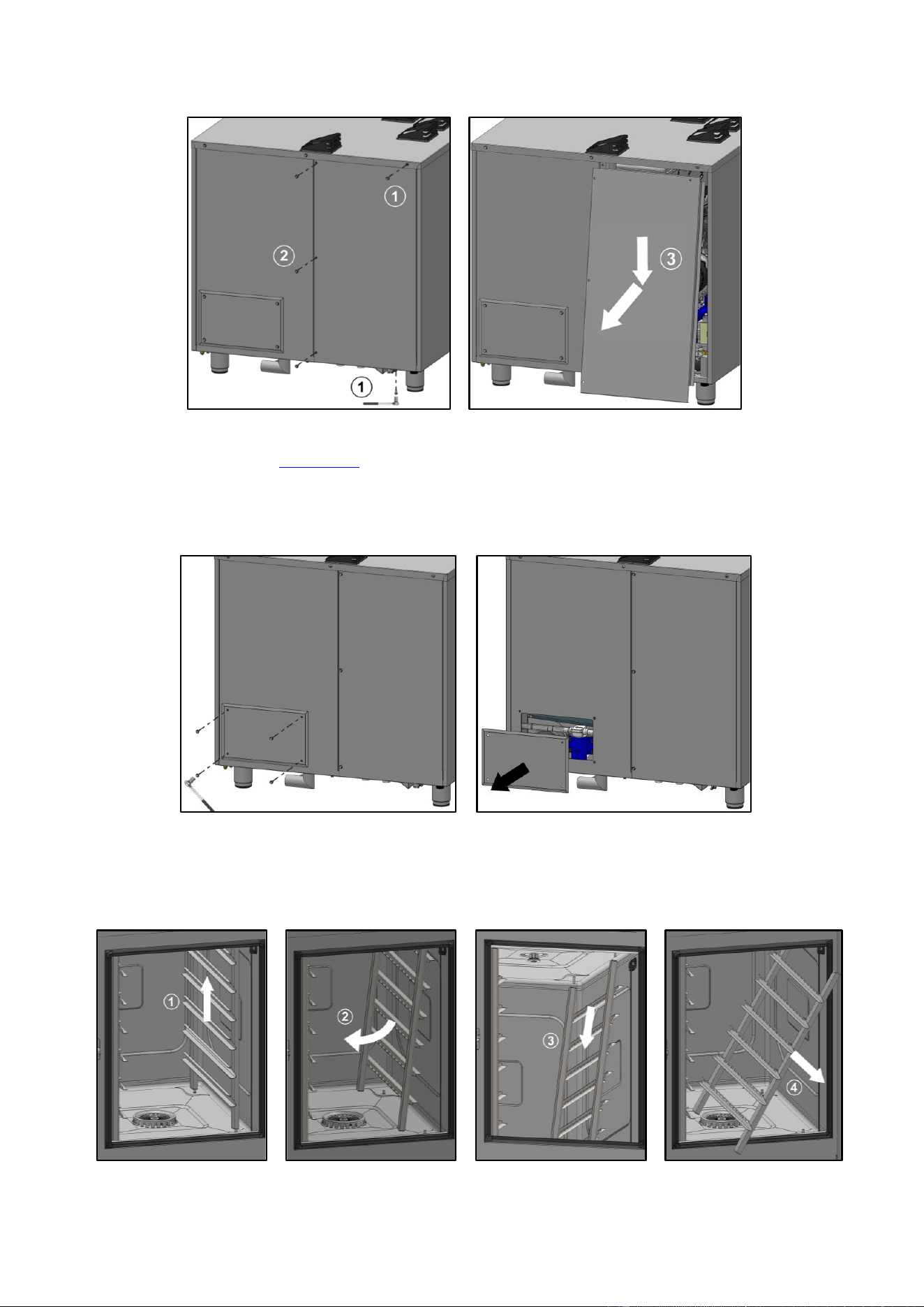
9 - ACCESS TO COMPONENTS
CHEF’SCOMBI
Page 58 / 76
3VE490099EM – 10/25
9.2.2 REAR PANEL (GAS APPLIANCE)
» Prepare your intervention:
✓ Tools: Wrenches.
» Remove the left oven panel (►Left side panel).
» Unscrew and remove the 2 x M5 screws securing the panel at the top and bottom and then the
3 x M5 screws securing the left-hand side of the half-panel.
» Remove the half-panel: Unhook bottom of the half-panel then lower it to remove .
9.2.3 REAR HATCH (GREASE COLLECTION OPTION)
» Prepare your intervention:
✓ Tools: Wrenches.
» Unscrew and remove the 4 x M5 screws securing the hatch cover to the rear panel.
» Remove the hatch cover.
9.2.4 RUNNERS
» Prepare the cooking cavity and check the following points:
✓ Remove all trays, plates and grids from the cooking cavity
✓ Verify the core probe has been removed from its housing
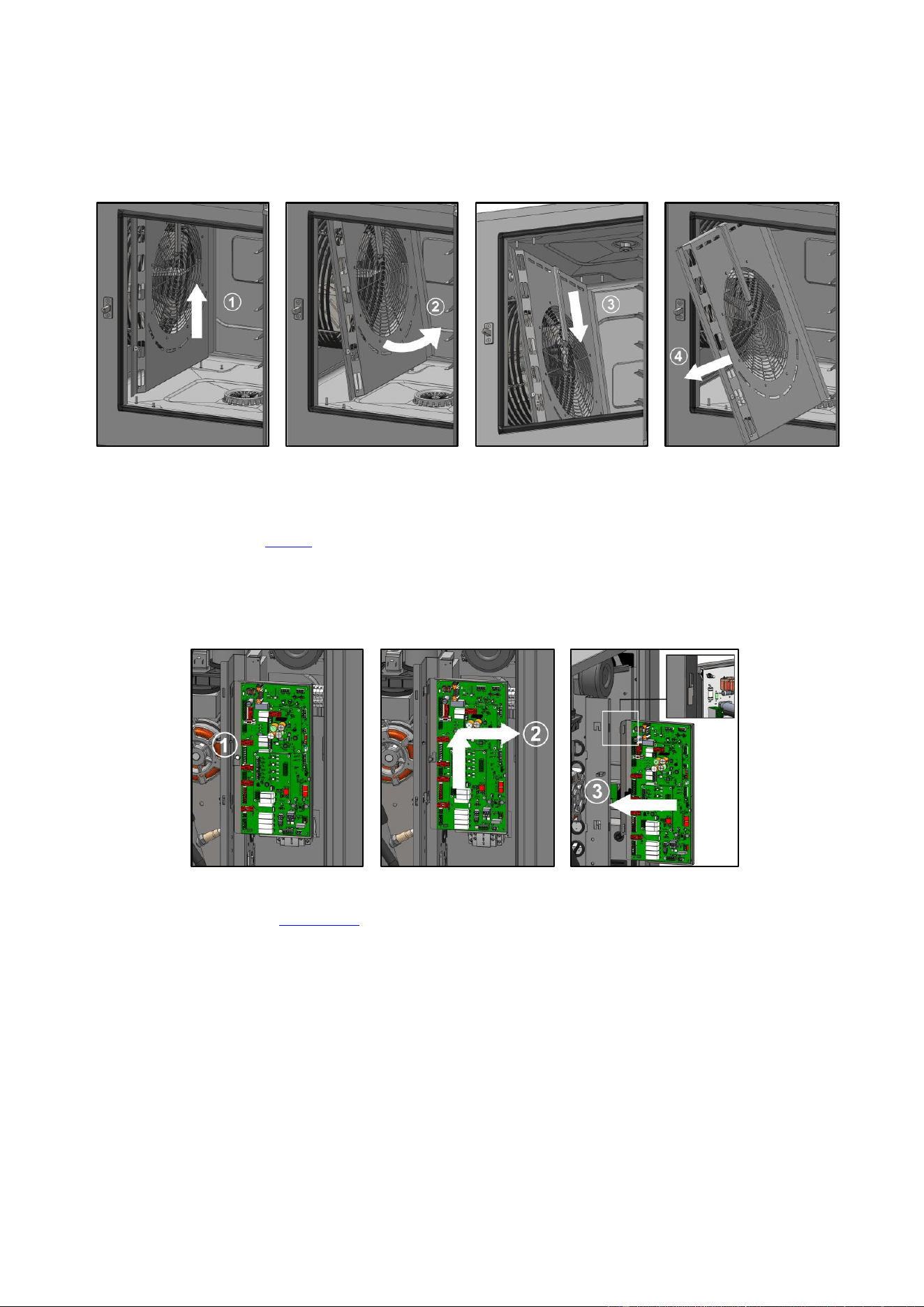
9 - ACCESS TO COMPONENTS
CHEF’SCOMBI
Page 59 / 76
3VE490099EM – 10/25
✓ Verify the USB core probe is not in the cooking cavity
» Lift the runner slightly by the middle of one of the upper levels .
» Tilt the runner towards the centre of the oven to release it from its lower supports (rear and front) .
» Release the runner from its upper supports (front and rear) .
» Remove the runner from cooking cavity .
9.2.5 VENTILATION DUCT
» Prepare the cooking cavity and check the following points:
✓ Remove all trays, plates and grids from the cooking cavity
✓ Verify the core probe has been removed from its housing
✓ Verify the USB core probe is not in the cooking cavity
✓ Protect bottom of the cavity with board
» Remove left-hand runner (►Runners).
» Lift the duct slightly .
» Tilt the duct to release it from its lower supports (rear and front) .
» Release the duct from its upper supports (front and rear) .
» Remove the duct from the cooking cavity.
9.2.6 MAINTENANCE POSITION OF THE MAIN BOARD
» Prepare your intervention:
✓ Tools: Wrenches
» Remove the left oven panel (►Left side panel).
» Slightly unscrew the screw securing the board to the electrical board .
» Lift up and remove the main board .
» Position the board in the 2 notches provided during maintenance operations .
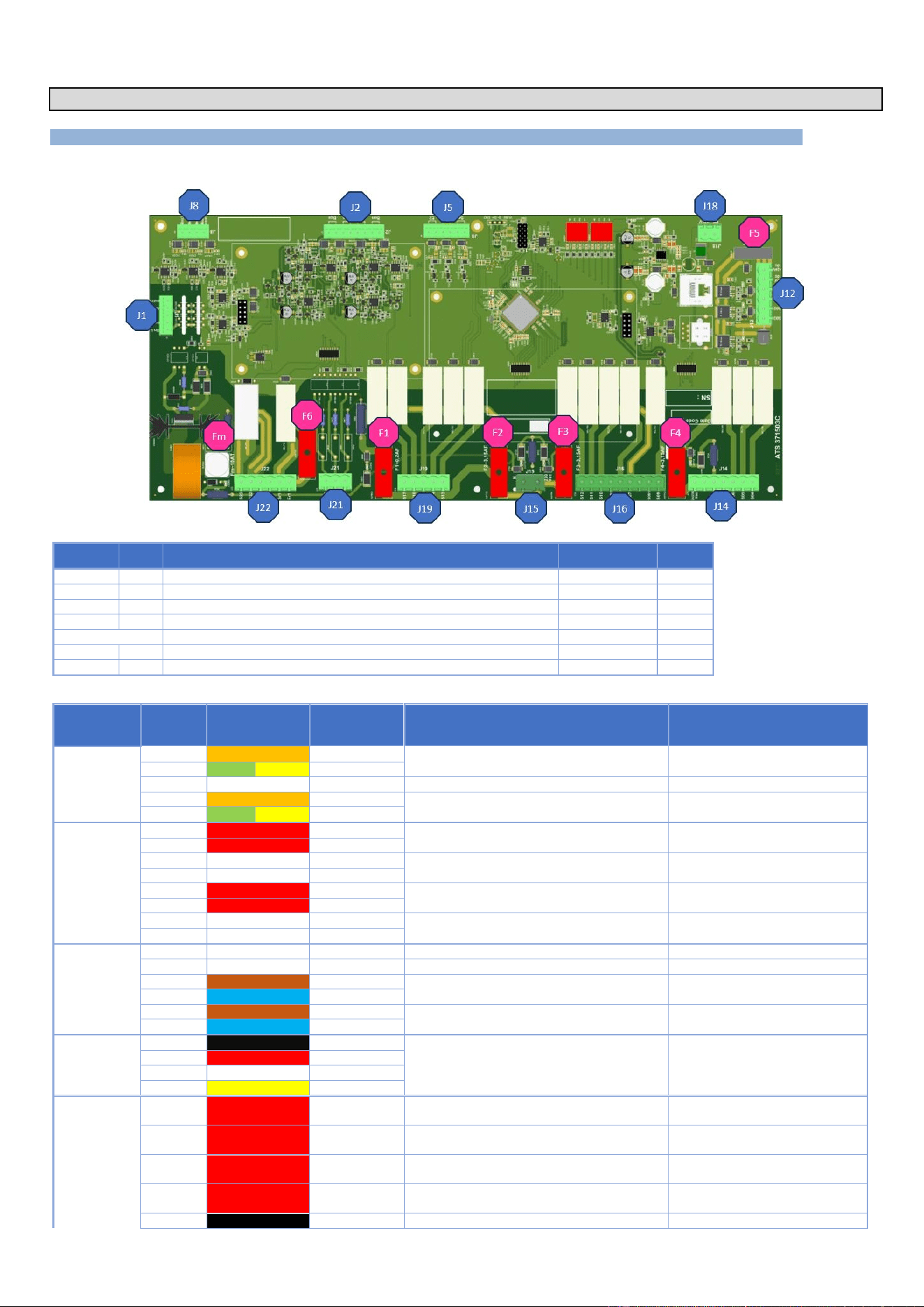
10 - COMPONENTS
CHEF’SCOMBI
Page 60 / 76
3VE490099EM – 10/25
10. COMPONENTS
10.1 ELECTRONIC BOARDS
10.1.1 MAIN BOARD - AR
Fuse
Ref.*
Function
Caliber
Size
Fm
Fm
Ventilation motor protection
10A Time-delay
5x20
F1
F1
Solenoid valve protection
0,2A Fast
5x20
F2
F2
Wash pump solenoid valve protection
3,15A Fast
5x20
F3
F3
Protection of Heating, technical ventilation and gas board power supply
3,15A Fast
5x20
F4
F4
Pump protection
3,15A Fast
5x20
F5
F5
24Vdc service protection
4A Fast
ATC
F6
F6
Potential-free contact protection (hood)
6,3A Fast
5x20
* References on electrical diagrams.
Connectors
Nber of
terminals
Color of wires
Destination
Function of the destination elements
Measurements
J1
2
Orange
BnL
Checks the water level in the cleaning box
5
G
Y
Earth
3
NC
4
Orange
BnC
Checks the water level in the steam generator
5
G
Y
Earth
J2
1
Red
Bga
Measures steam generator temperature
(safety input)
Value between 100 Ohms (35°F)
and 212 Ohms (572°F)
2
Red
Bga
3
White
Bgn
Measures steam generator temperature
(control input)
Value between 100 Ohms (35°F)
and 212 Ohms (572°F)
4
White
Bgn
5
Red
Baa
Measures cavity temperature (safety input)
Value between 100 Ohms (35°F)
and 212 Ohms (572°F)
6
Red
Baa
7
White
Ban
Measures the ambient temperature of the
cavity (control input)
Value between 100 Ohms (35°F)
and 212 Ohms (572°F)
8
White
Ban
J5
1
E2
2
E2
3
Brown
E1
Grease collection pressure switch option
Normally closed contact
4
Blue
E1
5
Brown
Sp
Control the closing of the door
6
Blue
Sp
J8
1
Black
PT100Bsc3
Value between 100 Ohms (35°F)
and 212 Ohms (572°F)
Take these mesures between
Yellow wire and each other wire
2
Red
PT100Bsc2
Food temperature control (3 levels)
3
White
PT100Bsc1
4
Yellow
Bsc com.
J12
1
Red
S03
Supplies the pump for the grease collection
option
24Vd.c. with Tc-
2
Red
S02
Supplies the In valve or the In valve contactor
(20-level ovens only)
24Vd.c. with Tc-
Red
S110
Supplies power to the LED lightning on the
oven door (20-level ovens only)
24Vd.c. with Tc-
4
Red
S01
Supplies power to the LED lightning on the
oven door
24Vd.c. with Tc-
5
Black
0Vd.c.
Not connected
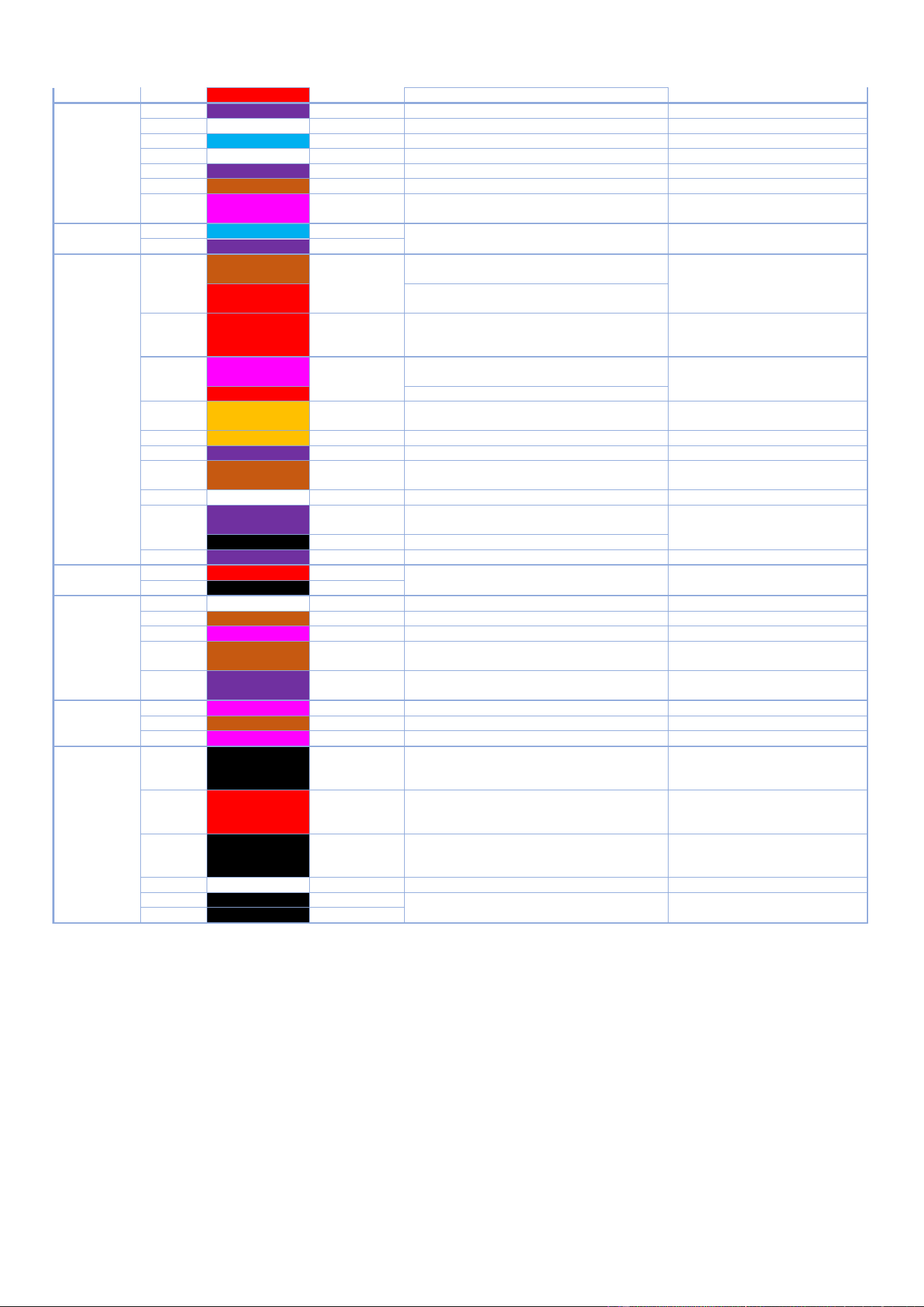
10 - COMPONENTS
CHEF’SCOMBI
Page 61 / 76
3VE490099EM – 10/25
6
Red
24Vd.c.
External power supply 24Vd.c. from Tc+
24Vd.c. with Tc-
J14
1
Purple
24/230Vac
supplies the 120Va.c pump.
120Vac with Nbt
2
-
3
Blue
Nbt
common pump supply 120Va.c.( neutral)
120Vac with 24/230Vac
4
-
5
Purple
Mdg - S06
activates the descaling pump 120Vac
120Vac with Nbt
6
Brown
Mvm - S05
activates the 120Vac cavity drain pump
120Vac with Nbt
7
Pink
Mvg - S04
activates the steam generator drain pump
120Vac
120Vac with Nbt
J15
1
Blue
Neutral
Supplies the 230Vac outputs
230Va.c. between these two
points
2
Purple
230Vac
J16
1
Brown
Chauf Vap-
S12
In an electric oven, activate the Kg steam
generator heating contactor(s)
230Va.c. with neutral
Red
In a gas oven, activates the steam generator
burner
2
Red
Chauf 2-S11
Not used in an electric oven
In a gas oven, activates the heating burner
(only 20 level oven)
230Va.c. with neutral
3
Pink
Chauf 1-S10
In an electric oven, activate the Kr (green)
control contactor(s)
230Va.c. with neutral
Red
In a gas oven, activate the heating burner
4
Orange
S081
In a gas oven, supplies the gas solenoid
valves
230Va.c. with neutral
5
Orange
Mtv1 - S08
Activates technical ventilation
230Va.c. with neutral
Purple
Mtv1 - S08
Activates technical ventilation
230Va.c. with neutral
6
Brown
Aag 230V - S07
Not used in electric ovens
Supplies the gas card of gas ovens
230Va.c. with neutral
7
-
-
-
8
Purple
XeA-S091
Controls the energy saver (electric oven)
Controls the second technical ventilation
230Va.c. with neutral
W1- 3
Controls the rotation speed of the hood
9
Purple
S09
Activates the power contactor(s) Kp
230Va.c. with neutral
J18
1
Red
+24VSyst
24Vd.c. power supply for Main board
24Vd.c. between 1 and 2
2
Black
0VSyst
J19
1
Reserve
S17
Reserved
2
Brown
Ydescal. - S16
Activates the powder dissolution solenoid valve
230Va.c. with neutral
3
Pink
Yspray - S15
Activates the spray hose solenoid valve
230Va.c. with neutral
4
Brown
S14
Activate the motor Air inlet contactor (20
levels ovens only)
230Va.c. with neutral
5
Purple
Cleaning pump
– S13
Activates the cleaning pump
230Va.c. with neutral
J21
1
Pink
Yboiler- S20
Activates the injection solenoid valve
230Va.c. with neutral
2
Brown
Ycool - S19
Activates the cooling solenoid valve
230Va.c. with neutral
3
Pink
Ycond. - S18
Activates the condenser solenoid valve
230Va.c. with neutral
J22
1
Black
S23
Activates clockwise motor rotation
208Va.c. with Xm0 for 208Va.c. oven
240Va.c. with Xm0 for 240Va.c. oven
230Va.c. with Xm0 for 480Va.c. oven
2
Red
S22
Activates anticlockwise motor rotation
208Va.c. with Xm0 for 208Va.c. oven
240Va.c. with Xm0 for 240Va.c. oven
230Va.c. with Xm0 for 480Va.c. oven
3
Black
E21
Supplies power to the motor
208Va.c. with Xm0 for 208Va.c. oven
240Va.c. with Xm0 for 240Va.c. oven
230Va.c. with Xm0 for 480Va.c. oven
4
-
-
-
5
W1-2
Sr1
Potential-free contact for hood motor control
Closed when the oven is operating
6
W1-1
Er1
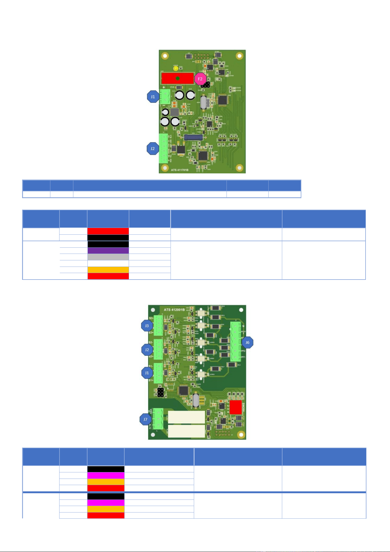
10 - COMPONENTS
CHEF’SCOMBI
Page 62 / 76
3VE490099EM – 10/25
10.1.2 HUMIDITY BOARD - AHU
Fuse
Ref.*
Function
Caliber
Size
F2
F2
Protect Humidity board
3.15A
5X20
* References on electrical diagrams.
Connectors
Nber of
terminals
Color of wires
Destination
Function of the destination elements
Measurements
J1
1
Red
Ahu/+
Humidity board power supply
24Vdc between these two points
2
Black
Ahu/-
J2
1
Black
Ah Blk
2
Violet
Ah Pure
3
Grey
Ah Gre
Supply humidity probe, heater unit and probe
4
White
AhWhi
feedback
5
Orange
Ah Yel
6
Red
Ah Red
10.1.3 GAS BOARD - AAG
Connectors
Nber of
terminals
Color of wires
Destination
Function of the destination elements
Measurements
J1
1
Black
GND/Alim- PWM
2
Pink
S1P/PWM input
Convection heat burner fan control
3
Orange
S1H/PWM Hall probe output
4
Red
+24Vdc/Alim+PWM
J2
1
Black
GND/Alim- PWM
2
Pink
S2P/PWM input
Convection heat burner fan control
only 20 levels
3
Orange
S2H/PWM Hall probe output
4
Red
+24Vdc/Alim+PWM
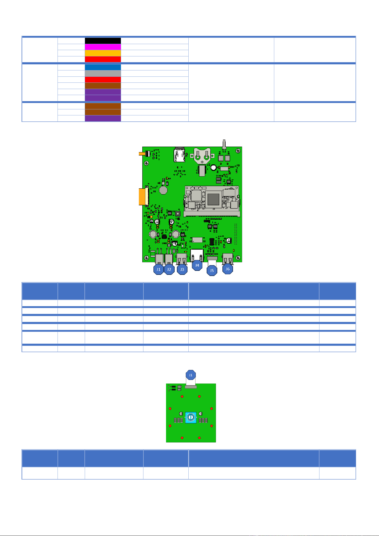
10 - COMPONENTS
CHEF’SCOMBI
Page 63 / 76
3VE490099EM – 10/25
J3
1
Black
GND/Alim- PWM
2
Pink
S1P/PWM input
Steam generator burner fan control
3
Orange
S1H/PWM Hall probe output
4
Red
+24Vdc/Alim+PWM
J6
1
Blue
Neutral
2
Grey
Secu3
3
Red
Secu 12
Flame and safety burner check
Flame control feedback at
230Va.c.
4
Brown
Pf3
5
Purple
Pf2
6
Purple
Pf1
J7
1
Brown
230Vac
230Va.c. between 230Va.c. and
Xb
3
Brown
AL3
Burner ignition control
2
Purple
AL12
10.1.4 INTERFACE BOARD - AI
Connectors
Nber of
terminals
Connectors type
Destination
Function of the destination elements
Measurements
J1
4-pin Molex connector
Not used
J2
4-pin Molex connector
Connects to the Main board
J3
USB connector
Connects the WIFI Dongle (Kit)
J4
RJ45
Ensures customer network connection for connectivity
J5
10-way ribbon connector
1.27mm pitch AWG28
Connects coder board to interface board
J6
USB connector
Connects front USB socket
10.1.5 CODER
Connectors
Nber of
terminals
Connectors type
Destination
Function of the destination elements
Measurements
J1
10-way ribbon cable
1.27mm pitch AWG 28
Connects coder board to the interface board
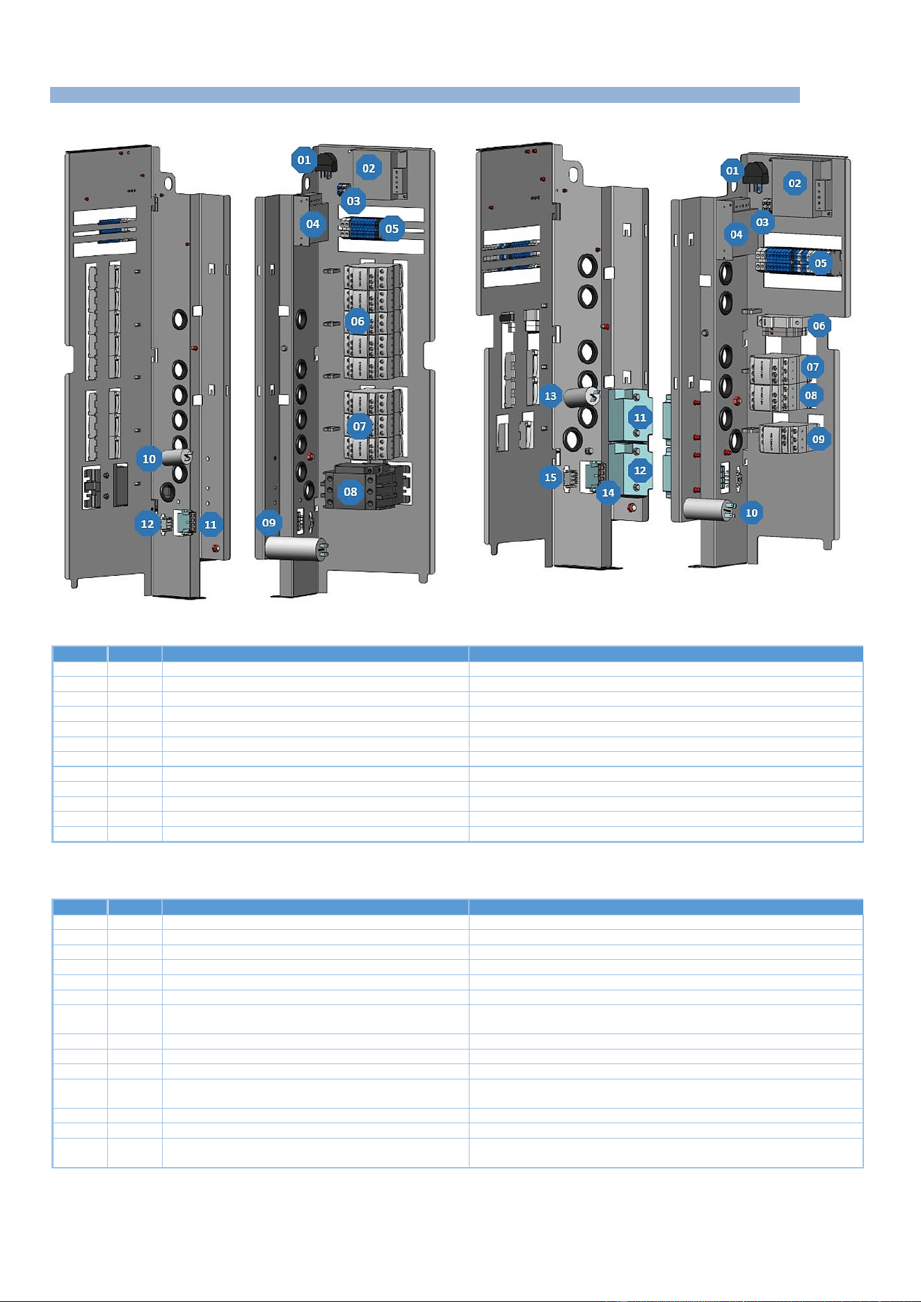
10 - COMPONENTS
CHEF’SCOMBI
Page 64 / 76
3VE490099EM – 10/25
10.2 ELECTRIC BOARDS
Electric ovens
Gas ovens
Electric ovens
Item
Ref.*
Description
Functions
1
La
EMC filter
Limits electromagnetic interference
2
Ta
Switching power supply
Supplies 24Vdc to services (lighting, In valve solenoid, grease gun)
3
Xe
Lighting terminal block
Connects LED strips for oven lighting
4
Tc
Switching power supply
Supplies 24Vdc to the Main board
5
X
Terminal block (Xa, Xb, X+, X-, Xm0, Xm1)
Connects the various power supplies
6
Kr
Convection heat control contactor
Supplies the heating elements with convection heat
7
Kg
Steam generator heating contactor
Supplies steam generator immersion heaters
8
Kp
Power contactor
Controls power to the oven
9
Cvm
Cooling fan
Starts the cooling fan
10
Cpl
Wash pump capacitor
Starts the wash pump
11
Xmv
Fan motor connector
Connects the fan motor to the board
12
Xpl
Wash pump connector
Connects the wash pump to the board
* References on electrical diagrams.
Gas ovens
Item
Ref.*
Description
Functions
1
La
EMC filter
Limits electromagnetic interference
2
Ta
Switching power supply
Supplies 24Vdc to services (lighting, In valve solenoid, grease gun)
3
Xth
Lighting terminal block
Connects LED strips for oven lighting
4
Tc
Switching power supply
Supplies 24Vdc to the Main board
5
X
Terminal block (Xa, Xb, X+, X-, Xm0, Xm1)
Connects the various power supplies
6
F
Protections (Ftco, Ftvb, Ftmv)
Protects the transformer and fan motor outputs (US model only)
7
Kr
Convection heating control switch
Controls the convection heater burner control board (1 or 2 depending
on the oven model)
8
Kg
Steam generator contactor
Controls the steam burner regulation board
9
Kp
Power contactor
Controls power to the oven
10
Cm
Cavity fan capacitor
Starts the cavity ventilation motor
11
Ear
Convection heating ignition transformer
Ignites the convection burner electrode (1 or 2 depending on the oven
model)
12
Eag
Steam generator ignition transformer
Ignites the steam generator burner electrode
13
Cpn
Wash pump capacitor
Starts the wash pump
14
Xm
Fan motor connector
Connects the fan motor to the board
15
Xpn
Wash pump connector
Connects the wash pump to the board
* References on electrical diagrams.
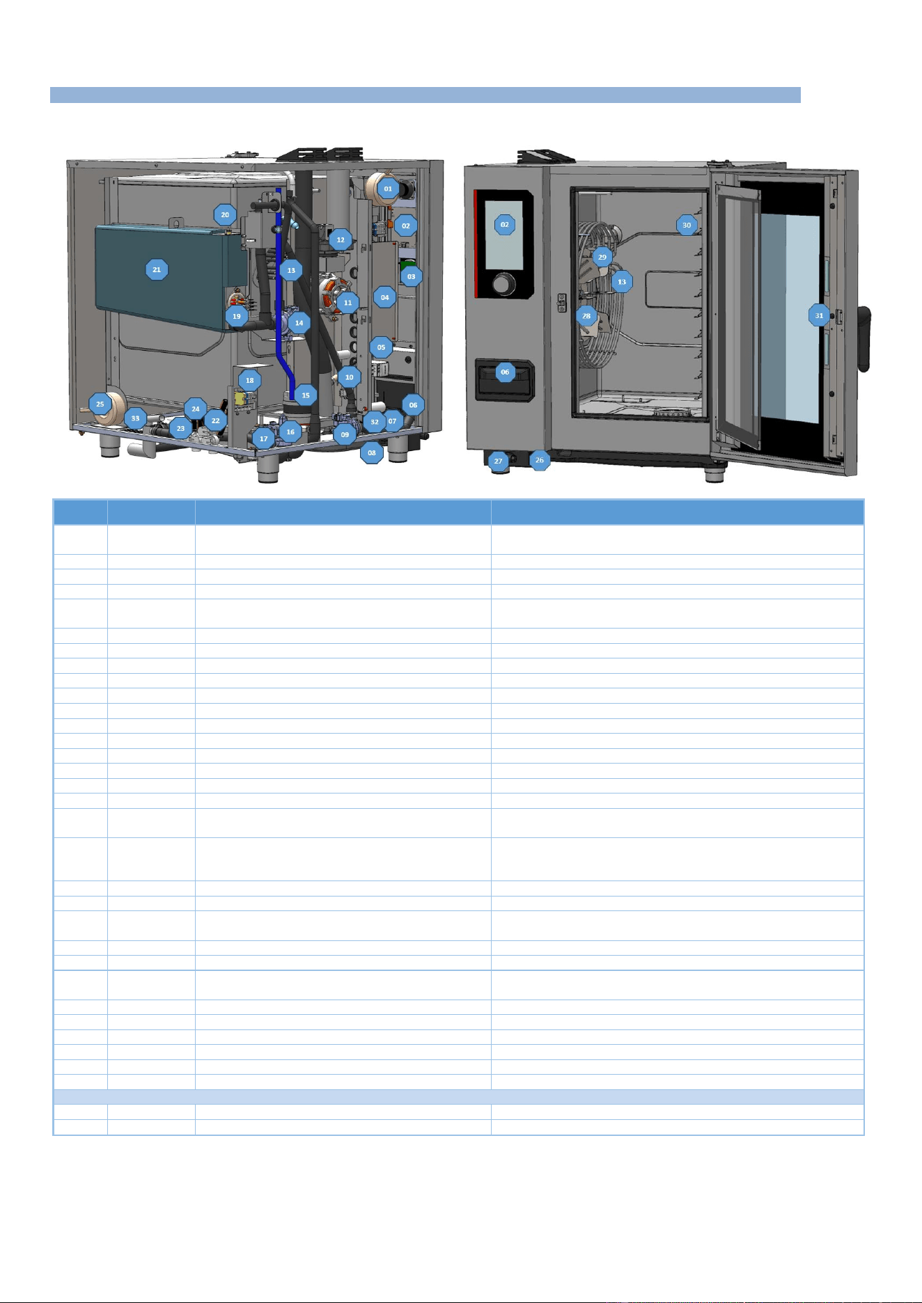
10 - COMPONENTS
CHEF’SCOMBI
Page 65 / 76
3VE490099EM – 10/25
10.3 OTHER COMPONENTS
10.3.1 ELECTRIC OVENS
Item
Ref.*
Description
Functions
1
Tco
Control auto transformer
(On certain models only) Ensures that customer voltage can be
matched to oven operating voltages
2
Ai
Interface board
Human-machine interface
3
Ac
Encoder board
Human-machine interface
4
Ar
Main board
Control all oven components
5
-
Electrical board
Provides the link between Main board commands and the
functions of external components
6
-
Descaling box
Contains descaling powder
7
Mt1-2
Technical fan
Ensure forced ventilation of the technical compartment
8
-
Spray hose reel
Contains spray hose reel
9
Mdg
Steam generator descaling pump
Ensures circulation of steam generator descaling agent
10
Shu
Humidity sensor
Humidity control
11
M1
Cavity fan motor
Ensures turbine rotation
12
Lo
Air inlet valve
Controls air inlet valve movements
13
Rc
Convection heating elements
Heats the inside of the cavity (several depending on model)
14
Mvg
Steam generator drain pump
Drain water from steam generator
15
Mpn
Cleaning pump
Ensures water circulation during cleaning phases
16
Mvm
Cavity drain pump
Ensures the draining of liquid elements contained in the cavity
17
Bnl
Clean box water level probe
Controls water level in clean box
18
Xp
Power terminal block
Allows the oven to be connected to the customer's electrical
network
19
Rg + Bg
Steam generator immersion heater + Temperature
probe
Heats the water contained in the steam generator, the sensor
controls the water temperature in the steam generator (safety and
regulation circuits).
20
Bnc
Steam generator water level probe
Controls water level in steam generator
21
-
Steam generator
Produce steam
22
Ycool - Yboiler
- Ydescal.
Triple solenoid valve
Controls filtered water supply cooling, steam generator filling and
descaling
23
Yspray - Ycond
Double solenoid valve
Controls unfiltered water inlet for spray hose and condenser
24
-
Clean box
Collects liquid elements contained in the cavity
25
Tmv
Cavity fan motor autotransformer
(On some models only) Adapts customer voltage to the voltage
used by the cavity fan motor
26
-
USB socket
Allows connection of a USB key for updates, backups, etc.
27
-
Spray hose
Cleans the oven
28
Ba
Cavity temperature probe
Controls oven cavity temperature (safety circuits and regulation)
29
M1
Fan
For even heat distribution
30
Bsc
3-point food core probe
Allows food temperature to be taken
31
Ee1 – Ee2
LED strips
Provide interior oven lighting (number depends on model)
Grease collection option
32
P
Pressure switch
Check no over pressure in the circuit.
33
Mpg
Grease pump
Drain grease from the cavity.
*References on electrical diagrams.
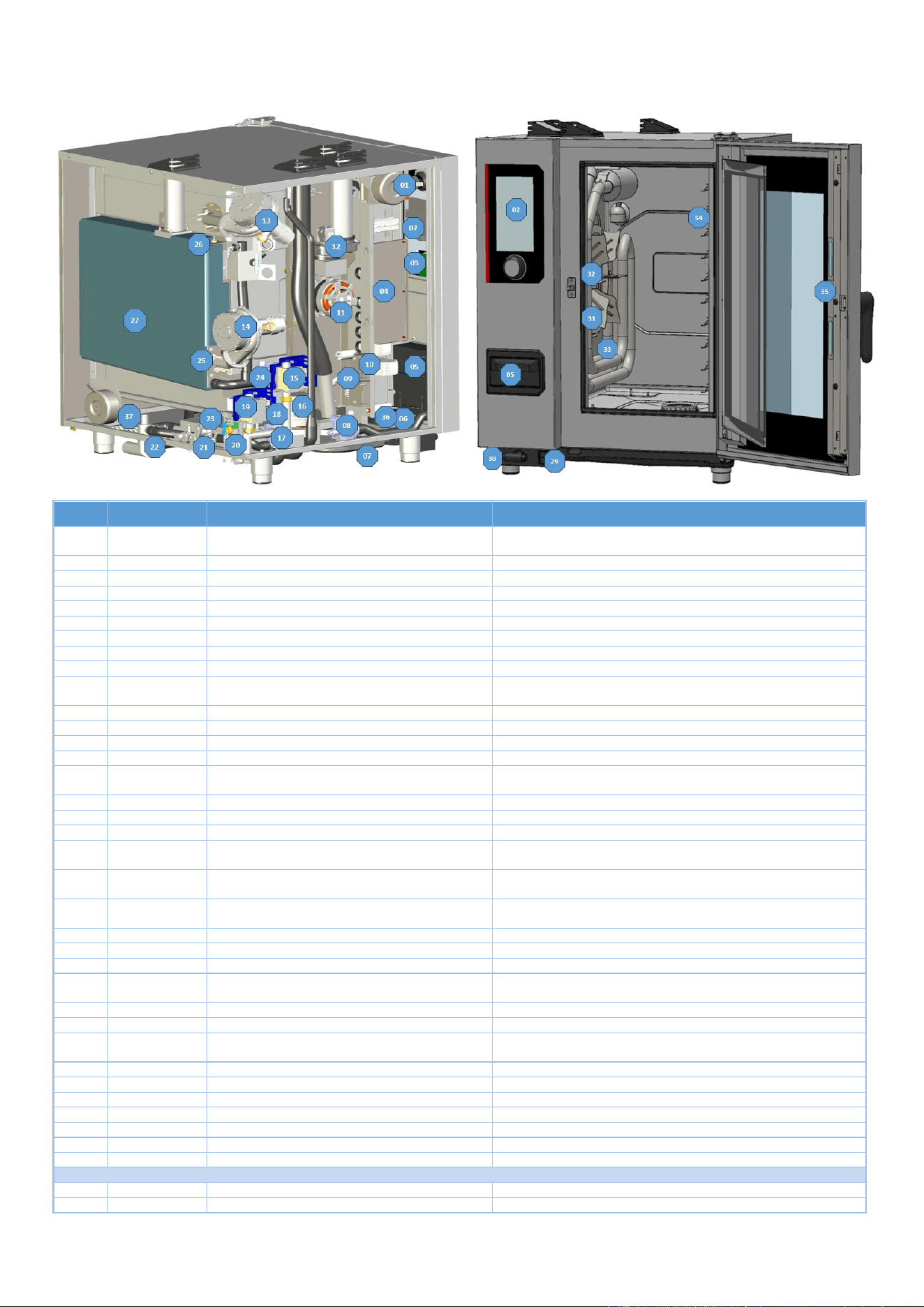
10 - COMPONENTS
CHEF’SCOMBI
Page 66 / 76
3VE490099EM – 10/25
10.3.2 GAS OVENS
Item
Ref.*
Description
Functions
1
Tco
Control auto transformer
(On certain models only) Ensures that customer voltage can be
matched to oven operating voltages
2
Ai
Interface board
Human-machine interface
3
Ac
Encoder board
Human-machine interface
4
Ar
Main board
Controls all oven components
5
-
Descaling box
Contains descaling powder
6
Mt1
Technical fan
Ensures forced ventilation of the technical compartment
7
-
Spray hose reel
Contains spray hose reel
8
Mdg
Steam generator descaling pump
Ensures circulation of steam generator descaling agent
9
Shu
Humidity sensor
Humidity control
10
-
Electrical board
Provides the link between Main board commands and the
functions of external components
11
M1
Cavity fan motor
Ensures turbine rotation
12
Lo
Air inlet valve
Controls air inlet valve movements
13
Mbr
Convection-heating burner motor
Supplies oxygen to the flame
14
Mbg
Steam generator burner motor
Supplies oxygen to the flame
15
Avr-1
Connection box of solenoid valve for convection
gas heating
Controls the solenoid valve for the gas supply to the convection-
heating burner
16
Mpn
Cleaning pump
Ensures water circulation during cleaning phases
17
Mvm
Cavity drain pump
Ensures the draining of liquid elements contained in the cavity
18
Bnl
Clean box water level probe
Controls water level in clean box
19
Avg
Connection box of solenoid valve for steam
generator gas control
Controls the solenoid valve of the gas supply to the steam
generator burner
20
Xp
Power terminal block
Allows the oven to be connected to the customer's electrical
network
21
Ycool - Yboiler -
Ydescal.
Triple solenoid valve
Controls filtered water supply cooling, steam generator filling and
descaling
22
Yspray - Ycond
Double solenoid valve
Controls infiltered water inlet for spray hose and condenser
23
-
Clean box
Collects liquid elements contained in the cavity
24
Mvg
Steam generator drain pump
Drain water from steam generator
25
Bg
Steam generator temperature probe
Controls temperature of the water in the steam generator (safety
circuit and regulation)
26
Bnc
Steam generator level probe
Controls water level in steam generator
27
-
Steam generator
Produce steam
28
Tmv
Cavity fan motor autotransformer
(On some models only) Adapts customer voltage to the voltage
used by the cavity fan motor
29
-
USB socket
Allows connection of a USB key for updates, backups, etc.
30
-
Spray hose
Cleans the oven
31
Ba
Cavity temperature probe
Controls oven cavity temperature (safety circuit and regulation)
32
M1
Fan
For even heat distribution
33
-
Gas exchanger
Heats the oven interior
34
Bsc
3-point food core probe
Allows food temperature to be taken
35
Ee1, Ee2
LED strips
Provide interior oven lighting (number depends on model)
Grease collection option
32
P
Pressure switch
Check no over pressure in the circuit.
33
Mpg
Grease pump
Drain grease from the cavity.
*References on electrical diagrams.
11 - RECOMMENDED AND EMERGENCY SPARE PARTS
CHEF’SCOMBI
Page 67 / 76
3VE490099EM – 10/25
11. RECOMMENDED AND EMERGENCY SPARE PARTS
Code
Vulcan Code
Description
Category
145587
00-977003
Drive shaft gasket + wear ring
Wearing Part
147147
00-978115
120W UL Motor service kit + ring + gasket
Recommended Part
148885
00-978275
Arched ignition electrode
Wearing Part
148886
00-978276
Straight Ionisation electrode
Wearing Part
148889
00-978277
Flame control electrode
Recommended Part
159005
00-978291
ICS24-61E - Service Kit Round heating element 11.2kW 230/240V
Recommended Part
159007
00-978292
ICS24-6~102E - Service Kit Round heating element 23.5kW 230/240V
Recommended Part
159008
00-978293
ICS24-101E - Service Kit Round heating element 19.6kW 230/240V
Recommended Part
159009
00-978294
ICS24-102E - Service Kit Round heating element 15,2kW 230/240V
Recommended Part
159010
00-978295
ICS24-61E - Service Kit Round heating element 10.3KW 208V
Recommended Part
159012
00-978296
ICS24-6~102E - Service Kit Round heating element 21,6kW 208V
Recommended Part
159013
00-978308
ICS24-101E - Service Kit Round heating element 18kW 208V
Recommended Part
159014
00-978298
ICS24-102E - Service Kit Round heating element 14kW 208V
Recommended Part
159015
00-978299
ICS24-61E - Service Kit Round heating element 10.3kW 277V
Recommended Part
159017
00-978300
ICS24-6~102E - Service Kit Round heating element 21.6kW 277V
Recommended Part
159018
00-978301
ICS24-101E - Service Kit Round heating element 18.0kW 277V
Recommended Part
159019
00-978302
ICS24-102E - Service Kit Round heating element 14kW 277V
Recommended Part
159022
00-978303
ICS24-61E - Service Kit Immersion heater 9,8kW 230/240V
Recommended Part
159023
00-978304
ICS24-6~10E - Service Kit Immersion heater 19.1kW 230/240V
Recommended Part
159024
00-978305
ICS24-61E - Service Kit Immersion heater 9kW 208V
Recommended Part
159025
00-978306
ICS24-6&10E Service Kit Immersion heater 17,5kW 208V
Recommended Part
159026
00-978307
ICS24-61E - Service Kit Immersion heater 9kW 277V
Recommended Part
159027
00-978308
ICS24-6~10E - Service Kit Immersion heater 17.5kW 277V
Recommended Part
159028
00-978309
ICS24-6&10E - Service Kit Temperature sensor
Recommended Part
159030
00-978311
ICS24 - Service Kit Ambient sensor
Recommended Part
159032
00-978313
ICS24 GN21 - Service Kit Motor
Recommended Part
159046
00-978325
ICS24-G- Service kit Gas fan NG40
Recommended Part
159048
00-978270
ICS24-61 - Service Kit Core temperature probe
Recommended Part
159049
00-978271
ICS24-102 - Service Kit Core temperature probe
Recommended Part
159050
00-978272
ICS24-62&101 - Service Kit Core temperature probe
Recommended Part
159053
01-556342
IC24-61&101 - Service kit for descaling pump
Recommended Part
159054
01-556343
IC24-62&102 - Service kit for descaling pump
Recommended Part
159060
01-556309
ICS24 - Service kit Fuses UL
Recommended Part
159064
01-556328
Kit after-sales service pressure switch
Recommended Part
159065
01-556370
ICS24-61&101 - Service Kit TPE-S AL Transparent pipe
Wearing Part
159066
01-556371
ICS24-62&102 - Service Kit TPE-S AL Transparent pipe
Wearing Part
300697
00-978061
Three-pole 25A 230V 50/60 Hz contactor
Recommended Part
300698
00-977007
Three-pole 32A 230V 50/60 Hz contactor
Recommended Part
300699
00-977375
Three-pole 40A 230V 50/60 Hz contactor
Recommended Part
300702
00-978065
Tree-pole 80A 230V 50/60 HZ contactor
Recommended Part
300769
00-977008
Anti-interference relay
Recommended Part
300787
00-977009
Ultra fast fuse 0.2A 250V 5 x 20
Recommended Part
300793
00-977014
600VAC fuse 10A 10.3 x 38.1
Recommended Part
300798
00-978062
Three-pole contactor 125A 230V 50/60 HZ
Recommended Part
300799
00-978064
Block RC LA4DA2U
Recommended Part
300801
00-978059
Glass fuse 4A
Recommended Part
300802
01-556134
Integrated switching power supply
Recommended Part
300805
00-978339
ICS24 - Door reed
Recommended Part
300806
00-978340
ICS24 - Door reed
Recommended Part
301514
00-978341
ICS24-6&10E - Boiler level sensor
Recommended Part
301515
00-978342
ICS24 - Humidity probe
Recommended Part
301519
00-978345
ICS24 - Wash box level probe
Recommended Part
301520
00-978346
ICS24-102E - Boiler level sensor
Recommended Part
304296
00-977018
Condenser 12.5µf
Recommended Part
304314
01-556135
Grease pump and fitting for hose diameter13
Recommended Part
304317
00-978350
ICS24 61E - Fan wheel
Recommended Part
304321
00-978351
ICS24 - Descaling pump 120V UL 60HZ 20L/min
Recommended Part
304322
00-978352
ICS24 - Drain pump wash box 120V UL 60HZ 20L/min
Recommended Part
304323
00-978353
ICS24 - Pump 120V UL 60HZ 20L/min
Recommended Part
304326
00-978354
ICS24 GN21 - Capacitor 25µ
Recommended Part
304328
00-978355
ICS24 61G 101E - Fan wheel 320
Recommended Part
304329
00-978356
ICS24 62E 101G - Fan wheel 340
Recommended Part
304330
00-978357
ICS24 62G 102E - Fan wheel 370
Recommended Part
304331
01-556310
ICS24 102G - Fan wheel 390
Recommended Part
304334
00-978358
ICS24 - Fan UL 230V 120 x 120 x 38 mm
Recommended Part
308353
00-978370
ICS24 - Switching power supply 24V 35W
Recommended Part
309407
00-977024
Fuse 3.15 Amps
Recommended Part
309608
00-978132
Filter with connection for gas oven
Recommended Part
309714
00-978375
FastPad 3 Interface Unit
Recommended Part
309716
00-978376
FastPad 3 Illuminated Optical Encoder
Recommended Part
309717
00-978377
FastPad 3 Gas board
Recommended Part

11 - RECOMMENDED AND EMERGENCY SPARE PARTS
CHEF’SCOMBI
Page 68 / 76
3VE490099EM – 10/25
Code
Vulcan Code
Description
Category
309718
00-978378
FastPad 3 Humidity board
Recommended Part
309719
00-978379
Led Strip 4000K 24V
Recommended Part
309720
00-978380
Automate board + Humidity board
Recommended Part
309725
00-978383
SELF common mode 2x10
Recommended Part
310356
00-978145
Security box
Recommended Part
310358
00-978386
Electromagnet GY030 24V
Recommended Part
311356
00-977221
LED strip label
Wearing Part
311361
00-977218
LED strip protective film
Recommended Part
314396
00-978083
UL Wash pump
Recommended Part
316192
01-556137
Transparent TPE-S AL Hose 12.7 x 20.1mm
Wearing Part
366068
00-978078 / 00-978096
Transparent silicone tube
Wearing Part
366572
00-977033
Door stop
Wearing Part
366683
00-978139
Outlet seal exchanger 6/10 levels
Wearing Part
366685
00-978152
Gas fan gasket
Wearing Part
366688
01-556144
FKM gasket 17,12x2,62mm
Wearing Part
366698
00-978432
ICS24-61 - Cooking cabinet gasket
Wearing Part
366699
00-978433
ICS24-62 - Cooking cabinet gasket
Wearing Part
366700
00-978434
ICS24-101 - Cooking cabinet gasket
Wearing Part
366701
00-978435
ICS24-102 - Cooking cabinet gasket
Wearing Part
366711
00-978441
ICS24 - Gasket In flap
Wearing Part
366712
00-978442
ICS24-GN11E - Immersion heater gasket
Wearing Part
384183
00-977034
Door closure mechanism
Recommended Part
384677
00-977035
Moulded door catch
Wearing Part
407002
00-978066
Anti-parasite module
Recommended Part
408402
00-978136
Gas ignition
Recommended Part
408407
00-978511
Auto Transformer 415 VA
Recommended Part
416003
00-978513
ICS24 - Hand shower kit
Wearing Part
468105
00-978545
ICS24 - Sub-assembly UL 2-way solenoid valve
Recommended Part
468107
00-978546
ICS24 - Sub-assembly UL 3-way solenoid valve
Recommended Part
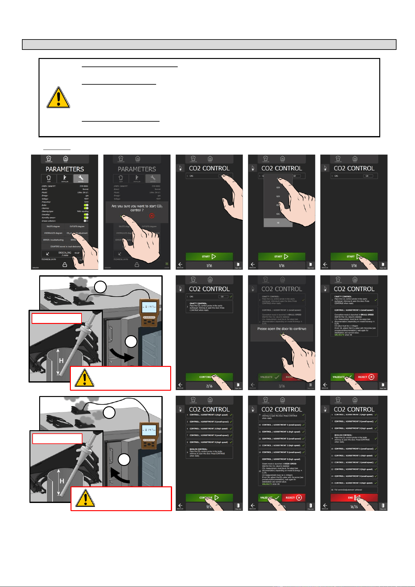
12 - COMBUSTION GAS ANALYSIS PROCEDURE
CHEF’SCOMBI
Page 69 / 76
3VE490099EM – 10/25
12. COMBUSTION GAS ANALYSIS PROCEDURE
WHO (can carry out this procedure):
Expert Technician (Trained on Combis – Trained for this Procedure)
EQUIPMENT (tool required):
Combustion Analyzer, complying with the local regulations, and:
- Analyzer technology should be with onboard CO2 probe (direct measure)
- If analyzer technology doesn’t have a CO2 probe (%CO2 = calculation), check that the correct gas has been
set in the analyzer, for the measure (mandatory for correct calculation)
WHEN (to do this procedure):
To switch from one gas to another
After changing Key Gas components as: Burner, Valve, Motor, Jet and exchanger
Procedure:
Prepare your check:
✓ Oven is connected to the water and wastewater systems, the electrical system and the gas supply line in
accordance with the recommendations and guidelines described in this manual.
✓ Measuring instrument for monitoring carbon dioxide CO
2
and carbon monoxide CO.
» Set the measuring instrument to "CO
2
" for a calculation result of "CO
2
rate in %".
1
2
H > 2" / 50mm
The probe must be inserted into
the gas chimney to measure
combustion values.
1
2
H > 2" / 50mm
The probe must be inserted into
the gas chimney to measure
combustion values.
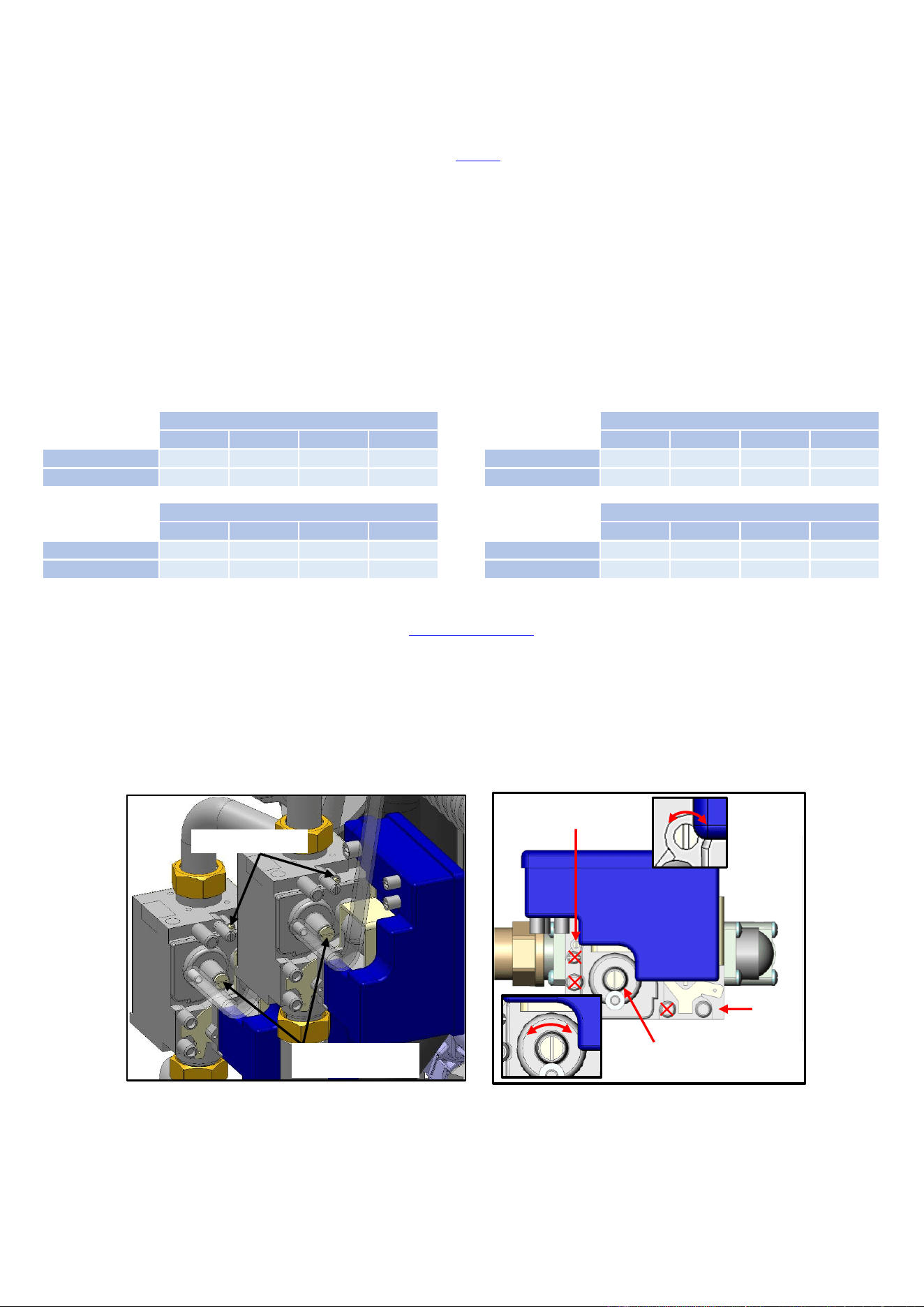
12 - COMBUSTION GAS ANALYSIS PROCEDURE
CHEF’SCOMBI
Page 70 / 76
3VE490099EM – 10/25
» From the "Home" menu screen, select "Settings" button.
The screen displays the "Parameters" menu with the "User" tab selected.
» Select "Service" tab.
The PIN code identification pop-up appears.
» Enter the PIN code (level 7) to access "Service" parameters (►Settings - PIN Codes).
» Confirm by pressing "✓ " icon. If the code is correct, access to the screen is authorised; if not, return to entering
the PIN code.
The screen displays the "Parameters" menu with the “Service” tab displayed.
» Press " CO
2
control & adjustment" button.
» Confirm by pressing « ✓ » icon.
The "CO
2
control" screen appears.
» Verify gas type matches the oven's supply gas.
» Start test by pressing the "Start" button.
» Place probe of the gas testing appliance in the cooking cavity flue gas chimney.
» Open the oven door.
» Press "Continue" button.
» Follow the information displayed on the oven screen and confirm by pressing « ✓ » icon if the measurement
values are correct.
The percentage of CO
2
measured must correspond within +/- 0.2% to the required value for the gas type in the
table below.
Each check is performed on 3 measurement readings.
Burner
Convection heat
CO2 (%) – Low speed
61
62
101
102
Gas A
10.4 ±0.2
10.7 ±0.2
10.1 ±0.2
10.0 ±0.2
Gas E
11.5 ±0.2
11.5 ±0.2
11.5 ±0.2
11.7 ±0.2
Burner (Generator)
Steam heat
CO2 (%) – Low speed
61
62
101
102
Gas A
10.6 ±0.2
10.4 ±0.2
9.5 ±0.2
9.5 ±0.2
Gas E
11.4 ±0.2
11.7 ±0.2
10.9 ±0.2
11.7 ±0.2
Burner
Convection heat
CO2 (%) – High speed
61
62
101
102
Gas A
10.3 ±0.2
10.4 ±0.2
9.9 ±0.2
10.1 ±0.2
Gas E
11.5 ±0.2
11.8 ±0.2
11.6 ±0.2
11.8 ±0.2
Burner (Generator)
Steam heat
CO2 (%) – High speed
61
62
101
102
Gas A
10.2 ±0.2
10.3 ±0.2
9.7 ±0.2
9.6 ±0.2
Gas E
11.6 ±0.2
11.4 ±0.2
11.1 ±0.2
11.7 ±0.2
» "If the percentage of CO
2
measured does not correspond to that requested for the gas used in the table above, adjust the
setting screws.
» Remove the left side panel to access the gas valves (►Access to components – Left-hand side panel).
» Adjust the CO
2
adjustment screw on the gas valve to set the CO
2
to « Low speed »:
- Remove the protective cap from the adjustment screw
- Adjust the setting by screwing/unscrewing the screw using a 4mm Allen key or Torx T25, a maximum of one turn at a
time (1% = 1 turn).
Turn clockwise to increase the
CO
2
level and anticlockwise to decrease the CO
2
level.
- After adjustment replace the protective cap.
» Adjust the RQ adjustment screw on the gas valve to set the CO
2
to « High speed »:
- Adjust the setting by screwing/unscrewing the screw using a 2.5mm Allen key or Torx T10, a maximum of a quarter
turn at a time.
Turn clockwise to decrease the
CO
2
level and anticlockwise to increase the CO
2
level.
» Follow "step by step" the actions displayed on the oven screen, validating if the measurement values are correct at each
step up to step 9.
» Place the probe of the gas testing appliance in the steam generator flue gas chimney.
» Close the oven door.
» Press the "Continue" button.
» Follow the information displayed on the oven screen and confirm by pressing the « ✓ » icon if the measurement values are
correct. If not, adjust the RQ or/and CO
2
adjustment screw on the corresponding gas valve, then confirm by pressing the
« ✓ » icon.
» When the display shows "Full control / adjustment achieved", press "End" to return to the previous screen.
Cap +
CO2 adjustment screw
RQ adjustment screw
CO
2
adjustment screw
P in
RQ adjustment screw
+ -
- +
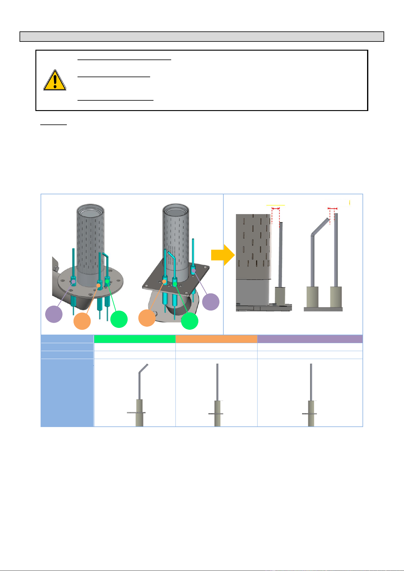
13 - CONTROL OF THE ELECTRODES (GAS BURNER)
CHEF’SCOMBI
Page 71 / 76
3VE490099EM – 10/25
13. CONTROL OF THE ELECTRODES (GAS BURNER)
WHO (can carry out this procedure):
Expert Technician (Trained on Combis – Trained for this Procedure)
EQUIPMENT (tool required):
- A rod / gauge by 0.24" diameter for the 3 electrodes (detection and flame detection).
- A rod / gauge by 0.12" (passes) and 0.16" (doesn’t pass) diameters for ignition electrodes.
WHEN (to do this procedure):
In case of unusual noise from burners (loud ignition, detonation, etc.),
Procedure:
» Record the noise,
» Note the Serial Number (see data plate),
» Remove the burner and control the position of ignition and flame detection electrodes (see drawing below):
- A wrong electrodes’ adjustment is the main reason to have abnormal noise.
- No need to check the combustion (except after changing some gas circuit components) or, worse, change the
combustion settings (screw …).
» Before changing anything in the Electrodes positions/ adjustments, take picture and measure the related positions (2
dimensions in the drawing bellow), and note any potential visible issue (deposits? …).
» Proceed to the setting / adjustment of the electrodes if out of the tolerances (see drawing). Change the electrodes if needed.
Convection heating burner
Steam generator burner
N°
1
2
3
Type
Ignition
Ignition
Flame detection
Code
148885
148886
148889
Visual
» Reassemble the burner / gas circuit and validate that the noise problem is resolved.
» Send all information to TECHNICAL SUPPORT: Serial Number, Gas & pressure, Noise record, setting before any change,
settings after change if needed … and global validation.
Check the 3 electrode
Check the ignition
electrodes
0.24" 0/+0.04
0.14" +/-0.02
1
3
2
3
1
2
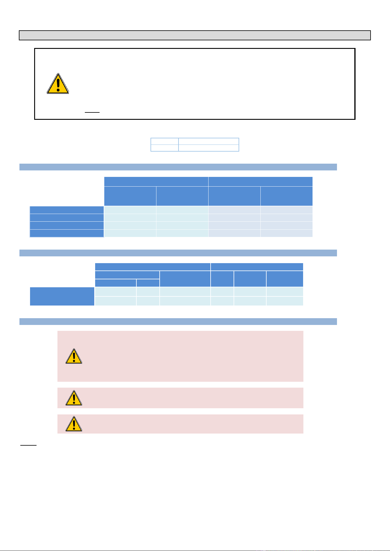
14 - CHANGING THE EQUIPMENT FROM ONE GAS TO ANOTHER
CHEF’SCOMBI
Page 72 / 76
3VE490099EM – 10/25
14. CHANGING THE EQUIPMENT FROM ONE GAS TO ANOTHER
The change of gas type can only be carried out by a technician authorised and trained by manufacturer, or by our
local representative.
Before any intervention, check with the owner which gas is currently in use in the kitchen.
Ensure that you are equipped with suitable measuring instruments (product analysis, gas water column pressure
gauge, gas leak detector etc.) and that they are in full working order. Without these instruments it is prohibited to
carry out any gas-related maintenance or adjustment!
Note : Connection/disconnection of the gas supply, as well as any maintenance or interventions are subject to the
local legislation in force.
In the following chapters, the different gases are designated by their international codification:
Gas A
NATURAL GAS
Gas E
PROPANE
14.1 GAS FLOW RATES AND POWERS
Gas power
Gas flow rates
Gas A
Gas E
Gas A
Gas E
6.5 - 10 inch w.c.
10 - 15 inch w.c.
Btu/h
Btu/h
ft3/h
lb/h
VICS61G / CHEF-61G
58006
54594
53.89
2.59
VICS62G / CHEF-62G
112601
102364
104.61
4.86
VICS101G / CHEF-101G
93834
88716
87.17
4.21
VICS102G / CHEF-102G
143310
136144
133.14
6.46
14.2 CHART OF GAS INJECTORS
GAS
INJECTORS
Designation
Pressure
Qty
Code
Family
Type
inch w.c. (mbar)
(1/100
e
)
Burners
Convection heat and
Steam heat
Natural gas
Gas A
6.5 – 10 (16 – 25)
-
-
-
Propane
Gas E
10 – 15 (25 – 38)
1
580
148 799
14.3 CHANGEOVER FROM ONE GAS TO ANOTHER:
Warning: Risk of poisoning!
When in use, connecting the wrong type of gas and/or setting the burners incorrectly can
lead to a serious risk of intoxication.
Connect the appliance only to the type of gas used.
Check that the appliance settings correspond to the type and pressure of the gas in the
installation.
Carry out a flue gas analysis when the appliance is commissioned for the first time.
We recommend installing a CO detector at the installation site.
The oven is equipped with 2 gas burners: one for convection heating and one for the
steam generator. It is essential to analyse the combustion gases at the outlet of the two
chimneys.
Caution: Gas leaks = danger for the user!
Check for leaks: This is a standard procedure and is your responsibility.
Notice
- The gas connection must be carried out by a qualified and certified gas fitter.
- Check that the appliance settings correspond to the type and pressure of the gas supplied to the installation.
- The gas connection pipe must be sized according to the nominal heat output and type of gas indicated on the nameplate. The cross-section
of the gas pipe must be at least 3/4".
- Connect the appliance to the gas supply pipe using a shut-off valve to isolate the appliance from the rest of the installation.
- Flue gas extraction must comply with local regulations.
- Flue gas analysis must be carried out before commissioning and only by a technician approved by the manufacturer.
- Check the gas supply for leaks using a suitable gas detector.
- All connecting parts on the installation site must be certified for gas use (e.g. NF gas; DVGW).
- A gas appliance with a mobile base must be installed using:

14 - CHANGING THE EQUIPMENT FROM ONE GAS TO ANOTHER
CHEF’SCOMBI
Page 73 / 76
3VE490099EM – 10/25
In EU: "Flexible gas approved in accordance with the regulations in force. (eg : NF TUBOGAZ length 0.75 m, Ø 15/21 (1/2")" without
flexible coupling, to be examined periodically and replaced if necessary.
In US: a connector that complies with the current standard (ANSI Z21.69 - CSA 6.16 US) (standard relating to connectors for mobile
gas appliances) and a quick disconnection device that complies with the current standard (ANSI Z21.41 - CSA 6.9 US) (standard
relating to quick disconnection devices for use with gaseous fuel)
Table of actions when switching from one gas to another:
According to the country of installation and the category of the appliance (indicated on the firm plate), the adaptation from one gas to another
may require 2 operations:
IN:
Addition or removal of injector
(Convection heat and steam burners (steam generator))
RV:
Gas valve adjustment (CO2 rate)
Research into the operations required to change gas:
» On the appliance firm plate, check:
- The category (ies) of the equipment.
- The gas and pressure for which it is adjusted.
» In the following chart, select
- The country concerned.
- The gas and the category of the appliance (previously identified)
- The gas and the pressure for which the appliance is going to be adjusted
- Identify the operations required when changing gas.
Countries concerned
Category and GAS OF ORIGIN (or new gas)
NEW GAS and Category (or gas of origin)
Required
operations
Gas
Gas
US - Canada
Gas A
Gas E
IN + RV
Procedure:
Prepare your connection and check the points below:
✓ A shut-off valve is fitted to isolate the appliance from the rest of the installation.
✓ The appliance is installed in the space provided.
✓ The appliance is securely positioned to avoid any risk of slipping.
✓ The appliance settings correspond to the type and pressure of the gas supplied to the installation (►Installation
manual).
✓ You will have the tools and measuring instruments you need for the connection (monitoring of carbon dioxide
CO2 and carbon monoxide CO), water column manometer, gas leak detector, etc…
» Connect the appliance tightly to the gas supply system (follow the standards in force) (►Installation manual).
» Remove the left-hand side panel of the oven (►Access to components).
» Check in the table above whether it is necessary to add or remove the gas injector depending on the new gas.
» Depending on the new gas, remove or insert the injector if necessary (►Chart of gas injectors) at the inlet of
the convection heating burner venturi and the steam burner venturi (steam generator) (►Gas diagram)
» Check for leaks (►Installation manual):
- Use leak detectors or spray to check the gas pipes and make sure there are no leaks.
- Check the pressure on the gas valve on the supply side:
▪ Unscrew the pressure screw by 2 to 3 turns and open the gas valve.
▪ Connect the water column hose to the pressure tap and close the gas valve.
▪ Monitor the water column level for 1 minute. An unchanged reading at -1 mbar is expected.
- Check the static pressure (appliance not in operation):
▪ Check the pressure using a water column.
▪ The reading must be the same as or higher than the pressure specified on the nameplate.
» Check the connection pressure/dynamic pressure (►Installation manual):
- Connect a water column pressure gauge to the pressure tap when the burner is in operation (all gas
appliances in operation, burners on).
- The gas pressure measured in this way must be within the pressure range indicated on the nameplate for
the gas used (►Installation manual).
» Set the measuring instrument to "CO
2
" for a calculation result of "CO
2
rate in %".
» From the "Home" menu screen, select the "Settings" button.
The screen displays the "Parameters" menu with the "User" tab selected.
» Select the "Service" tab.
The PIN code identification pop-up appears.
» Enter the PIN code (level 7) to access the "Service" parameters (►Settings - PIN Codes).
» Confirm by pressing the "✓ " icon. If the code is correct, access to the screen is authorised; if not, return to
entering the PIN code.
The screen displays the "Parameters" menu with the “Service” tab displayed.
» Press the " CO
2
control & adjustment" button.
» Confirm by pressing the « ✓ » icon.
The "CO
2
control" screen appears.
» Set up the oven with the new gas.
- Press the gas type field.
The pop-up with the list of gases appears.
- Select the desired gas type (Gas A = GA, Gas E = GE)
The gas type is changed in the field.
» Start the test by pressing the "Start" button (►Combustion gas analysis procedure).
» When the display shows "Full control / adjustment achieved", press "End" to return to the previous screen.
» On the new gas plate, fill in the gas corresponding to the gas for which the appliance has been set.
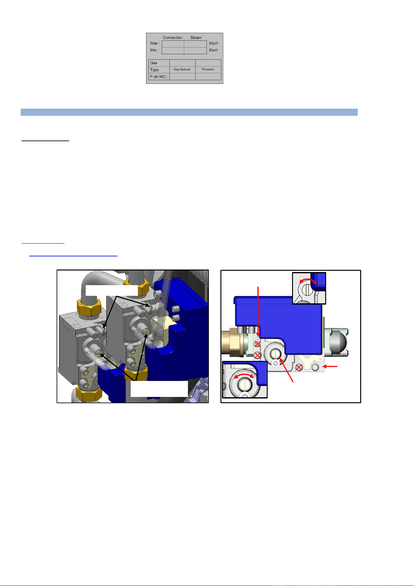
14 - CHANGING THE EQUIPMENT FROM ONE GAS TO ANOTHER
CHEF’SCOMBI
Page 74 / 76
3VE490099EM – 10/25
» Stick the new gas plate in place.
14.4 CHANGING/ADJUSTING GAS VALVE
When replacing a gas valve, it is imperative to carry out a leak check and adjust the gas valve by performing a flue gas analysis.
Checking for leaks (►Installation manual)
» Use leak detectors or spray to check the gas pipes and make sure there are no leaks.
» Check the pressure on the gas valve on the supply side:
- Unscrew the pressure screw by 2 to 3 turns and open the gas valve.
- Connect the water column hose to the pressure tap and close the gas valve.
- Monitor the water column level for 1 minute. An unchanged reading at -1 mbar is expected.
» Check the static pressure (appliance not in operation):
- Check the pressure using a water column.
- The reading must be the same as or higher than the pressure specified on the nameplate.
» Check the connection pressure/dynamic pressure:
- Connect a water column pressure gauge to the pressure tap when the burner is in operation (all gas
appliances in operation, burners on).
- The gas pressure measured in this way must be within the pressure range indicated on the nameplate for
the gas used (►Installation manual).
Valve adjustment
MANDATORY carry out a burnt gas analysis and adjust the RQ and CO2 screws of the gas valve if necessary, for a CO<150ppm
(►Combustion gas analysis procedure).
The evacuation of combustion gases must comply with local legislation.
Cap +
CO2 adjustment screw
RQ adjustment screw
CO
2
adjustment screw
P in
RQ adjustment screw
+ -
- +
15 - CONVERSION TABLES
CHEF’SCOMBI
Page 75 / 76
3VE490099EM – 10/25
15. CONVERSION TABLES
15.1 PT100 PROBE
PT100 probe components
Temperature probe comprises a resistance probe with the value of 100 ohms for a temperature of 0° and 138.5 ohms for a temperature of 100°C. The
variation of the resistance to temperature relationship is linear. The resistance reading is directly proportional to the measured temperature. The probe
is not polarised. The probe can be extended using copper wire.
Temperature in °F relative to Resistance in for PT100 probe
°F
0
1
2
3
4
5
6
7
8
9
30
100.00
100.22
100.43
100.65
100.87
101.09
101.30
101.52
40
101.74
101.95
102.17
102.39
102.60
102.82
103.04
103.25
103.47
103.69
50
103.90
104.12
104.34
104.55
104.77
104.98
105.20
105.42
105.63
105.85
60
106.07
106.28
106.50
106.71
106.93
107.15
107.36
107.58
107.79
108.01
70
108.23
108.44
108.66
108.87
109.09
109.30
109.52
109.73
109.95
110.17
80
110.38
110.60
110.81
111.03
111.24
111.46
111.67
111.89
112.10
112.32
90
112.53
112.75
112.96
113.18
113.39
113.61
113.82
114.04
114.25
114.47
100
114.68
114.90
115.11
115.33
115.54
115.76
115.97
116.18
116.40
116.61
110
116.83
117.04
117.26
117.47
117.68
117.90
118.11
118.33
118.54
118.76
120
118.97
119.18
119.40
119.61
119.82
120.04
120.25
120.47
120.68
120.89
130
121.11
121.32
121.53
121.75
121.96
122.18
122.39
122.60
122.82
123.03
140
123.24
123.46
123.67
123.88
124.09
124.31
124.52
124.73
124.95
125.16
150
125.37
125.59
125.80
126.01
126.22
126.44
126.65
126.86
127.08
127.29
160
127.50
127.71
127.93
128.14
128.35
128.56
128.78
128.99
129.20
129.41
170
129.62
129.84
130.05
130.26
130.47
130.68
130.90
131.11
131.32
131.53
180
131.74
131.96
132.17
132.38
132.59
132.80
113.01
133.23
133.44
133.65
190
133.86
134.07
134.28
134.50
134.71
134.92
135.13
135.34
135.55
135.76
200
135.97
136.19
136.40
136.61
136.82
137.03
137.24
137.45
137.66
137.87
210
138.08
138.29
138.51
138.72
138.93
139.14
139.35
139.56
139.77
139.98
220
140.19
140.40
140.61
140.82
141.03
141.24
141.45
141.66
141.87
142.08
230
142.29
142.50
142.71
142.92
143.13
143.34
143.55
143.76
143.97
114.18
240
144.39
144.60
144.81
145.02
145.23
145.44
145.65
145.86
146.07
146.28
250
146.49
146.70
146.91
147.11
147.32
147.53
147.74
147.95
148.16
148.37
260
148.58
148.79
149.00
149.21
149.41
149.62
149.83
150.04
150.25
150.46
270
150.67
150.88
151.08
151.29
151.50
151.71
151.92
152.13
152.33
152.54
280
152.75
152.96
153.17
153.38
153.58
153.79
154.00
154.21
154.42
154.62
290
154.83
155.04
155.25
155.46
155.66
155.87
156.08
156.29
156.49
156.70
300
156.91
157.12
157.33
157.53
157.74
157.95
158.15
158.36
158.57
158.78
310
158.98
159.19
159.40
159.61
159.81
160.02
160.23
160.43
160.64
160.85
320
161.05
161.26
161.47
161.67
161.88
162.09
162.29
162.50
162.71
162.91
330
163.12
163.33
163.53
163.74
163.95
164.15
164.36
164.57
164.77
164.98
340
165.18
165.39
165.60
165.80
166.01
166.21
166.42
166.63
166.83
167.04
350
167.24
167.45
167.66
167.86
168.07
168.27
168.48
168.68
168.89
169.09
360
169.30
169.51
169.71
169.92
170.12
170.33
170.53
170.74
170.94
171.15
370
171.35
171.56
171.76
171.97
172.17
172.38
172.58
172.79
172.99
173.20
380
173.40
173.61
173.81
174.02
147.22
174.43
174.63
174.83
175.04
175.24
390
175.45
175.65
175.86
176.06
176.26
176.47
176.67
176.88
177.08
177.29
400
177.49
177.69
177.90
178.10
178.30
178.51
178.71
178.92
179.12
179.32
410
179.53
179.73
179.93
180.14
180.34
180.55
180.75
180.95
181.16
181.36
420
181.56
181.77
181.97
182.17
182.38
182.58
182.78
182.98
183.19
183.39
430
183.59
183.80
184.00
184.20
184.40
184.61
184.81
185.01
185.22
185.42
440
185.62
185.82
186.03
186.23
186.43
186.63
186.84
187.04
187.24
187.44
450
187.65
187.85
188.05
188.25
188.45
188.66
188.86
189.06
189.26
189.46
460
189.67
189.87
190.07
190.27
190.47
190.67
190.88
191.08
191.28
191.48
470
191.68
191.88
192.09
192.29
192.49
192.69
192.89
193.09
193.29
193.49
480
193.70
193.90
194.10
194.30
194.50
194.70
194.90
195.10
195.30
195.50
490
195.71
195.91
196.11
196.31
196.51
196.71
196.91
197.11
197.31
197.51
500
197.71
197.91
198.11
198.31
198.51
198.71
198.91
199.11
199.31
199.51
510
199.71
199.91
200.11
200.31
200.51
200.71
200.91
201.11
201.31
201.51
520
201.71
201.91
202.11
202.31
202.51
202.71
202.91
203.11
203.31
203.51
530
203.71
203.91
204.11
204.31
204.51
204.71
204.90
205.10
205.30
205.50
540
205.70
205.90
206.10
206.30
206.50
206.70
206.89
207.09
207.29
207.49
550
207.69
207.89
208.09
208.29
208.48
208.68
208.88
209.08
209.28
209.48
560
209.67
209.87
210.07
210.27
210.47
210.67
210.86
211.06
211.26
211.46
570
211.66
211.85
-
-
-
-
-
-
-
-
How to read the chart:
To find the resistance corresponding to a temperature of 364°F.
- Find the intersection of the line 360°F and the column 4°F.
- The reading shows 169.92 Ohms.
Check
m
PT100
Check probe resistance with an ohmmeter set to 200 ohms (less than 107 ohms for 68°F).
Check the probe insulation between one of the leads and the metal part with the ohmmeter set at 20 mega
ohms (a value over 15 mega ohms).
Check the continuity between the feed and the metal part of the probe.
15 - CONVERSION TABLES
CHEF’SCOMBI
Page 76 / 76
3VE490099EM – 10/25
15.2 CELSIUS / FAHRENHEIT TEMPERATURE
Value in °C
Value in °F
Specific temperatures
23°C
73°F
Maximum cold water inlet temperature
(city or softened)
25°C
77°F
Minimum temperature in Convection
mode and Mixed mode
30°C
86°F
Minimum temperature in Steam mode
35°C
95°F
40°C
104°F
45°C
113°F
50°C
122°F
55°C
131°F
60°C
140°F
Maximum operating temperature for
cleaning products
65°C
149°F
70°C
158°F
75°C
167°F
Maximum electronic temperature
80°C
176°F
85°C
185°F
90°C
194°F
95°C
203°F
100°C
212°F
10°C
230°F
Value in °C
Value in °F
Specific temperatures
120°C
248°F
130°C
266°F
Maximum temperature in steam mode
140°C
284°F
150°C
302°F
160°C
320°F
170°C
338°F
180°C
356°F
No-Fail mode operating temperature
190°C
374°F
200°C
392°F
210°C
410°F
220°C
428°F
230°C
446°F
240°C
464°F
250°C
482°F
260°C
500°F
270°C
518°F
280°C
536°F
290°C
554°F
300°C
572°F
Maximum temperature in Convection
mode and Mixed mode
400°C
752°F
Safety temperature
15.3 WATER HARDNESS
°dH
°f
°e
ppm
mmol/l
gr/gal
mval/kg
CaO
[mg/l]
CaCO3
[mg/l]
Ca2+
[mg/l]
1 °f
(France)
0.56
1
0.70
10,0
0.1
0.584
0.2
5.60
10.0
4.00
1 °e
(GB)
0.8
1.43
1
14.25
0.14
0.83
0.284
7.98
14.25
5.71
1 °dH
(Germany)
1
1.78
1.25
17.9
0.1783
1.042
0.357
10
17.85
7.15
1 ppm
(USA)
0,056
0.1
0.07
1
0.01
0.0584
0.02
0.56
1.0
0.40
1 gr/gal
(USA)
0.96
1.71
1.20
17.1
0.171
1
0.342
9.60
17.11
6.85
1 mmol/l
5.60
10.01
7.02
100.1
1
5.84
2
56.07
100.1
40.08
1 mval/kg
2.8
5.0
3.51
50
0.5
2.92
1
28.04
50.0
20.04
15.4 PRESSURE
kPa
bar
mbar
psi
Inch / wc
0,1
0.001
1
0,0145
0,4019
0,2
0.002
2
0,0290
0,8037
0,3
0,003
3
0,0435
1,2056
0.4
0,004
4
0,0580
1,6075
0.5
0,005
5
0,0725
2,0093
0.6
0,006
6
0,0870
2,4112
0.7
0,007
7
0,1015
2,8131
0.8
0,008
8
0,1160
3,2149
0.9
0,009
9
0,1305
3,6168
1
0,01
10
0,1450
4,0187
2
0,02
20
0,2901
8,0373
3
0,03
30
0,4351
12,0560
4
0,04
40
0,5802
16,0746
5
0,05
50
0,7252
20,0933
6
0,06
60
0,8702
24,1119
7
0,07
70
1,0153
28,1306
8
0,08
80
1,1603
32,1492
9
0,09
90
1,3053
36,1679
10
0,1
100
1,4504
40,1865
20
0,2
200
2,9008
80,3730
30
0,3
300
4,3511
120,5595
kPa
bar
mbar
psi
Inch / wc
40
0,4
400
5,8015
160,7460
50
0,5
500
7,2519
200,9325
60
0,6
600
8,7023
241,1190
70
0,7
700
10,1527
281,3055
80
0,8
800
11,6030
321,4920
90
0,9
900
13,0534
361,6785
100
1
1000
14,5038
401,8650
150
1,5
1500
21,7557
602,7975
200
2
2000
29,0076
803,7300
250
2,5
2500
36,2595
1004,6625
300
3
3000
43,5114
1205,5950
350
3,5
3500
50,7633
1406,5275
400
4
4000
58,0152
1607,4600
450
4,5
4500
65,2671
1808,3925
500
5
5000
72,5190
2009,3250
550
5,5
5500
79,7709
2210,2575
600
6
6000
87,0228
2411,1900
700
7
7000
101,5266
2813,0550
800
8
8000
116,0304
3214,9200
900
9
9000
130,5342
3616,7850
1000
10
10000
145,0380
4018,6500