User Manual
"Prior to installation and use, read and follow all instructions
and warnings in this manual. Keep this manual for Owner’s
future reference. Do not discard or destroy.
CONNECTOR
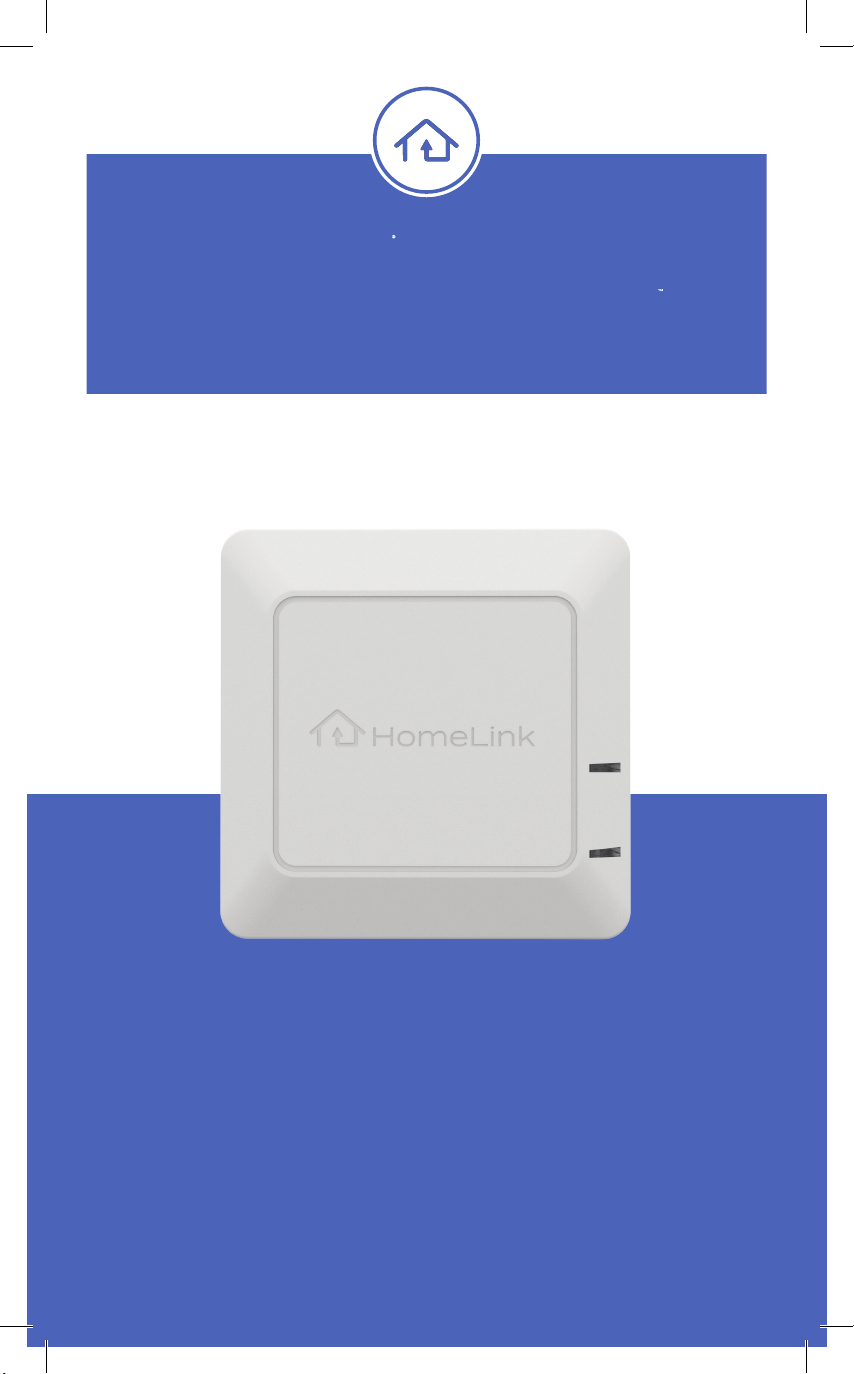
HomeLink Smart Home
550-0836-000-AAA_HL_Connector_Manual__UPDATE.indd 1550-0836-000-AAA_HL_Connector_Manual__UPDATE.indd 1 12/31/25 9:37 AM12/31/25 9:37 AM
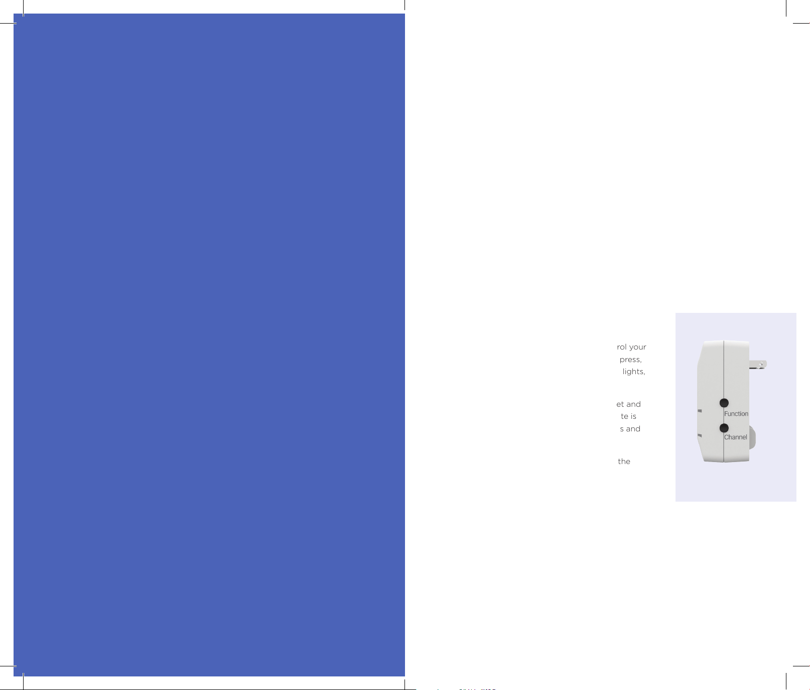
Table of Contents
Important Safety Information .............................................................................3
What’s in the box? .................................................................................................... 3
Device Overview ........................................................................................................3
Quick Start Guide......................................................................................................4
Alarm.com Dealers ..............................................................................................5
DIY (Do It Yourself) ............................................................................................. 6
Additional Instructions ...........................................................................................7
Inclusion of the Connector into your Z-Wave network .....................7
Removing the Connector from your Z-Wave network ...................... 7
Programming a channel in the Connector ...............................................8
Erasing a channel in the Connector ............................................................ 8
Factory reset ..........................................................................................................8
Programming HomeLink in Your Vehicle .......................................................9
Programming Instructions ............................................................................... 9
Erasing Programmed HomeLink Buttons ................................................9
Interpreting Status Lights ..................................................................................... 9
FUNCTION Light ..................................................................................................9
CHANNEL Light .................................................................................................... 9
Status Light Reference Table ........................................................................ 10
Supported Command Classes ............................................................................11
Configuration Parameters .................................................................................... 12
Channel Learning Process ................................................................................... 15
Association Command Classes ......................................................................... 17
Association Groups Documentation .......................................................... 17
Association Groups ................................................................................................. 17
Important Notes ....................................................................................................... 21
Quick Reference Table ........................................................................................... 21
Indicator Class ........................................................................................................... 22
Support ......................................................................................................................... 22
Federal Communications Commission (FCC) ............................................ 23
Important Safety Notes ........................................................................................ 23
Limited Warranty ..................................................................................................... Back Cover
Important Safety Information
This safety alert symbol " and the term WARNING in this manual alert you to potential
serious injury hazards.
Read and follow all instructions and warnings in this manual to help avoid injury or death.
" WARNING
• INGESTION HAZARD: Handheld remote includes two small coin batteries.
A swallowed coin battery can cause Internal Chemical Burns in as little as 2 hours.
• KEEP new and used batteries OUT OF REACH OF CHILDREN.
• Seek immediate medical attention if battery is suspected to be swallowed or inserted
in any part of body.
• Device intended for use in indoor locations only.
What’s in the box?
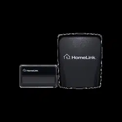
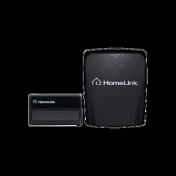
• The HomeLink® Smart Home Connector™
• Handheld remote (batteries included)
• User Manual
Device Overview
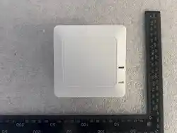
The HomeLink® Smart Home Connector™ allows you to
use the HomeLink® buttons in your vehicle to control your
Z-Wave® smart home system. With a single button press,
you can trigger customized scenes—like turning on lights,
adjusting the thermostat, or locking doors.
The Connector plugs into a standard U.S. wall outlet and
comes with a separate handheld remote. This remote is
used to program your in-vehicle HomeLink® buttons and
can also trigger Z-Wave scenes directly.
You can program up to six different scenes* using the
Connector.
This product can be operated in any Z-Wave network with
other Z-Wave certified devices from other manufacturers.
All mains-operated nodes within the network will act
as repeaters regardless of vendor to increase reliability
of the network.
2 33
* A scene is a group of smart home actions (like turning off lights, locking doors, adjusting thermostat)
that can be triggered by a single HomeLink button press. Each channel on the Connector can activate
a different scene.
550-0836-000-AAA_HL_Connector_Manual__UPDATE.indd 2-3550-0836-000-AAA_HL_Connector_Manual__UPDATE.indd 2-3 12/31/25 9:37 AM12/31/25 9:37 AM
Quick Start Guide
The HomeLink® Smart Home Connector™ can be installed in two different ways
depending on your smart home setup. Please review the descriptions below
to determine which set of instructions best fits your situation:
Alarm.com Dealers
Follow these instructions if your system is professionally installed and
managed by an Alarm.com dealer. These steps are tailored for technicians
using the Alarm.com MobileTech app and are designed to enable Z-Wave
Long Range through SmartStart setup.
DIY (Do It Yourself)
Use these steps if you’re setting up the device yourself, without the help
of an Alarm.com professional. This guide assumes you’re using a standard
Z-Wave controller (like a hub from SmartThings, Hubitat, or similar) and
may not support Z-Wave Long Range or SmartStart features, depending
on your system.
Alarm.com Dealers
1. Scan the Connector’s DSK QR code using MobileTech. This will allow the device
to learn in via SmartStart, which is required to enable Z-Wave Long Range.
2. Plug your Connector into a standard 120 VAC outlet. It is intended for interior use.
Ideally it should be placed between where you park your vehicle and your Alarm.com
panel. Suggested locations include an attached garage, a breezeway, inside entryway
or foyer—and best if visible from your vehicle. Once the Connector is plugged
in, a blue light should begin to blink. (If it does not, see the section titled
“Factory reset” below.)
3. Confirm that the Connector has been added to your Z-Wave network. This can take
several minutes. If after 10 minutes the Connector is still not added to the network,
or if the device is not properly recognized, remove it from the network following the
steps under “Removing the Connector from your Z-Wave network,” plug it in as close
as possible to the Z-Wave controller and try SmartStart again.
4. Train HomeLink in your vehicle with the handheld remote. Bring the new handheld
remote to your vehicle. (For more information see the “Vehicle HomeLink Programming”
below or visit the full instructions online at homelink.com/program).
a. Press and hold the vehicle-installed HomeLink® button you’d like to train AND
any one of your handheld remote buttons until the HomeLink® light changes
from a slow flash to a fast flash (typically 10 to 20 seconds).
b. Repeat for each button you’d like to program to an Alarm.com scene.
5. Program HomeLink in-vehicle buttons to Connector. Now that the HomeLink buttons
in your vehicle know how to communicate with the Connector (in the previous step),
the in-vehicle buttons presses can be assigned to any of the available Connector
channels, 1 through 6.
a. Press the FUNCTION button on the Connector. The FUNCTION light should
be flashing blue to indicate it is in programming mode.
b. Press the CHANNEL button on the Connector to select the channel you’d like
to program (1 through 6). The CHANNEL light flashes will indicate what channel
is selected. For example, if it flashes 3 times, channel 3 is selected.
c. In your vehicle, press the HomeLink button you’d like to assign to that channel
within 30 seconds. When successful the FUNCTION light will turn green
or 5 seconds.
d. After the FUNCTION light turns off, confirm the Connector is receiving signals
from your in-vehicle HomeLink module. Do this by pressing the assigned HomeLink
button, the FUNCTION light should quickly blink green.
e. Repeat steps a-c for each channel you’d like to assign to a button.
6. Set up your scenes with Alarm.com. Now that everything is set up and connected,
you can go to your Alarm.com mobile app and configure your Connector scenes.
Navigate to the Scenes, Configure Remotes page to create remote-triggered scenes
for your car buttons. The app will lead you through the final steps.
4 5
550-0836-000-AAA_HL_Connector_Manual__UPDATE.indd 4-5550-0836-000-AAA_HL_Connector_Manual__UPDATE.indd 4-5 12/31/25 9:37 AM12/31/25 9:37 AM

DIY (Do It Yourself)
1. If your Z-Wave system supports SmartStart, scan the device QR code. SmartStart
allows the product to be added into a Z-Wave network by scanning the Z-Wave QR
code with a controller providing SmartStart inclusion. If your system does not support
SmartStart, skip this step.
2. Plug your Connector into a standard 120 VAC outlet. It is intended for interior use.
Ideally it should be placed between where you park your vehicle and your Alarm.com
panel. Suggested locations include an attached garage, a breezeway, inside entryway
or foyerr—and best if visible from your vehicle. Once the Connector is plugged
in, a blue light should begin to blink. (If it does not, see the section titled
“Factory reset” below.)
3. Put your Z-Wave Controller into inclusion mode. If using SmartStart, no further
action is required, the HomeLink Connector will be added automatically within
10 minutes of it being switched on in the network vicinity. If not using SmartStart,
reference the instructions that came with your Z-Wave Controller as this step will
be unique for each system.
4. Confirm that the Connector has been added to your Z-Wave network. This can take
several minutes. If after 10 minutes the Connector is still not added to the network, or
if the device is not properly recognized, remove it from the network. Plug it in as close
as possible to the Z-Wave controller and try again.
5. Train HomeLink in your vehicle with the handheld remote. Bring the new
handheld remote to your vehicle. (For more information see the “Vehicle HomeLink
Programming” below or visit the full instructions online at homelink.com/program )
a. Press and hold the vehicle-installed HomeLink® button you’d like to train AND
any one of your handheld remote buttons until the HomeLink® light changes from
a slow flash to a fast flash (typically 10 to 20 seconds).
b. Repeat for each button you’d like to program to an Alarm.com scene.
6. Program HomeLink in-vehicle buttons to Connector. Now that the HomeLink buttons
in your vehicle know how to communicate with the Connector (in the previous step),
the in-vehicle buttons presses can be assigned to any of the available Connector
channels, 1 through 6.
a. Press the FUNCTION button on the Connector. The FUNCTION light should be
flashing blue to indicate it is in programming mode.
b. Press the CHANNEL button on the Connector to select the channel you’d like
to program (1 through 6). The CHANNEL light flashes will indicate what channel
is selected. For example, if it flashes 3 times, channel 3 is selected.
c. In your vehicle, press the HomeLink button you’d like to assign to that channel within
30 seconds. When successful the FUNCTION light will turn green for 5 seconds.
d. After the FUNCTION light turns off, confirm the Connector is receiving signals
from your in-vehicle HomeLink module. Do this by pressing the assigned HomeLink
button, the FUNCTION light should quickly blink green.
e. Repeat steps a-c for each channel you’d like to assign to a button.
7. Set up your Z-Wave scenes. Now that everything is set up and connected, you can go
to your Z-Wave controller and configure your Connector scenes. You can assign each
of the 6 channels to do a unique scene in your smart home automation system. Please
reference the instructions for your controller for more information.
Additional Instructions
Add the Connector into your Z-Wave network
This function is only available if the unit is not connected to a Z-Wave network, either
because it is new, or because it has been removed from the network or factory reset.
If your system supports SmartStart, scan the DSK QR Code on the back of the
product or this manual with your Z-Wave system controller and then plug in the device.
No further action is required, it will be added automatically within 10 minutes.
For systems that do not support SmartStart, the unit will automatically go into Z-Wave
inclusion mode when it is plugged in. If the unit has not been included via SmartStart
within 1 minute of power on, it will enter classic Z-Wave inclusion mode.
While in inclusion mode, FUNCTION will blink blue. It will flash solid green when the
Connector has been connected to the network.
Note: This device utilizes S2 for Z-Wave inclusion which provides a higher level of
security. However, it also increases the likelihood of inclusion errors in larger networks.
If you experience an error during this process, remove the connector from the Z-Wave
network (as described in the following section), temporarily move the device very
close to your Z-Wave panel or controller, and retry the inclusion process.
Remove the Connector from your Z-Wave network
First, set your Z-Wave controller to exclusion mode, sometimes this is found under
an option to “remove a device.”
If you are an Alarm.com installer, use MobileTech and follow these steps:
1. Go to Equipment, then Z-Wave Devices
2. Expand the Z-Wave Actions drop down at the top of the screen
3. Press Delete Z-Wave Devices
4. Wait for the bolded message: “Checking for new devices on the network.”
Alternatively, to set your Qolsys panel to clear a device, follow these steps:
5. Press Settings in the swipe-down settings tray
6. Press Advanced Settings and enter an installer code (default is 1111)
7. Press Installation, then Devices and then Z-Wave Devices
8. Press Add Device and then Include
9. Press Clear Device
Once your Z-Wave controller is set to exclusion mode, continue by pressing and holding
the FUNCTION button on the Connector until the light is yellow, then release.
The FUNCTION light will blink yellow when the Connector is waiting to be removed
from the network. It will blink green when it has successfully been removed. It will then
return to the inclusion mode, ready for adding to a Z-Wave network, indicated by the
FUNCTION light blinking blue.
If the remove fails, the FUNCTION light will flash red for five seconds then return to
normal state. Try the above steps again. If it is not successful after repeated attempts,
you may need to perform a factory reset on the Connector to return it to inclusion mode.
6 7
550-0836-000-AAA_HL_Connector_Manual__UPDATE.indd 6-7550-0836-000-AAA_HL_Connector_Manual__UPDATE.indd 6-7 12/31/25 9:37 AM12/31/25 9:37 AM

Programming a channel in the Connector
• Press and hold the FUNCTION button until the light is blue, then release
• Press the CHANNEL button a number of times to select the desired channel.
Channel number starts at 1 and goes to 6. The CHANNEL light will blink a number
of times to indicate what channel is currently selected.
• Press the desired HomeLink or handheld remote button
• The FUNCTION light will turn green for 5 seconds when the connection is made.
If the connection is not made within 30 seconds the FUNCTION light will flash red
for five seconds then return to normal state.
Note: If the same HomeLink or handheld remote button is associated with a second
channel the association with the first channel will automatically be deleted. A remote
button can only be associated with one channel.
Erasing a channel in the Connector
• Press and hold the FUNCTION button until the light is white, then release.
• Press the CHANNEL button a number of times to select the desired channel.
Channel number starts at 1 and goes to 6. The CHANNEL light will blink a number
of times to indicate what channel is currently selected.
• Press the FUNCTION and CHANNEL button simultaneously.
• The FUNCTION light will turn green when the deletion is complete.
Factory reset
Press and hold the FUNCTION button and CHANNEL button simultaneously until both
lights blink red (for about 5 seconds), then release.
All programmed channels and Z-Wave network information will be erased – the device
will restart in a factory state. A blinking blue FUNCTION light indicates it is ready to be
included in a new Z-Wave network.
Vehicle HomeLink Programming
Programming Instructions
In-vehicle HomeLink programming instructions vary by vehicle make, model and year.
Visit homelink.com/program for the most accurate instructions.
A summarized version:
1. Press and hold the HomeLink button you’d like to train AND any one of your handheld
remote buttons until the HomeLink® light changes from a slow flash
to a fast flash (typically 10 to 20 seconds).
Once programmed, see “Programming a channel in the Connector” to associate the button
to a Connector channel.
Erasing Programmed HomeLink Buttons
To clear all data from your HomeLink in-vehicle, press and hold the first and third
button for 10-seconds or until the light blinks rapidly. Please proceed with due caution
as this will completely reset your HomeLink buttons, erasing all trained buttons.
8 9
550-0836-000-AAA_HL_Connector_Manual__UPDATE.indd 8-9550-0836-000-AAA_HL_Connector_Manual__UPDATE.indd 8-9 12/31/25 9:37 AM12/31/25 9:37 AM
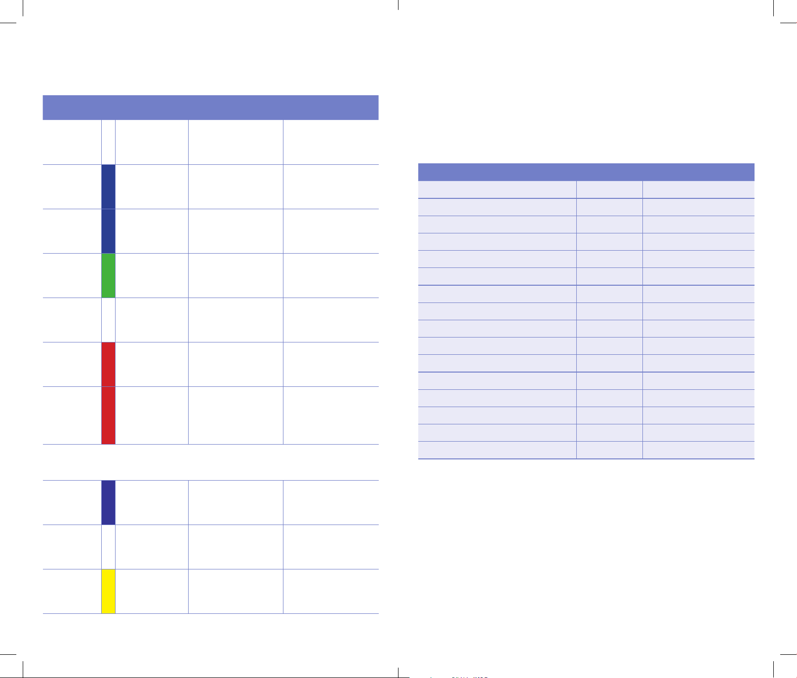
Status Light Reference Table
Light Color / Behavior Meaning What to Do
FUNCTION
White (solid,
fades out)
Power-on sequence
complete
No action needed
FUNCTION Blinking Blue
In Z-Wave inclusion
mode (ready to join
network)
Start inclusion process
on your Z-Wave
controller
FUNCTION
Blinking Blue
(5 seconds)
Z-Wave indicator set
command for locating
device
No action needed
FUNCTION
Blinking Green
(3 seconds)
Signal received
from HomeLink or
handheld remote
Confirms a command
was received
FUNCTION Pulsing White
Firmware update
in progress
Wait until update
completes
FUNCTION
Flashing Red
(5 seconds)
Operation failed
(e.g., programming
timeout)
Retry the action
CHANNEL
Blinking
(1–6 times)
Indicates selected
channel during
programming or erase
Count blinks to
determine which
channel is selected
(e.g., 3 blinks =
channel 3)
Status Light Table when holding the FUNCTION button
FUNCTION Solid Blue
Ready to program
a channel
Release button,
continue programming
steps
FUNCTION Solid White
Ready to erase
a channel
Release button, then
follow erase steps
FUNCTION Solid Yellow
Ready to remove
device from Z-Wave
network
Release button,
follow Z-Wave
exclusion steps
Supported Command Classes
Technical information for advanced users.
This device uses the Configuration Command Class (Version 4) to allow parameter
customization. Each parameter, including ID, size, and default value, is described
in the Configuration Parameters section of the product manual.
The following table lists all supported command classes, their versions, and their
required security levels.
Command Class Version Security Level
Z-Wave Plus Info V2 None
Security 0 V1 S0
Security 2 V1 S2 Authenticated
Transport Service V2 None
Supervision V1 S2 Authenticated
Association V2 S2 Authenticated
Association Group Info V3 S2 Authenticated
Multi Channel Association V3 S2 Authenticated
Central Scene V3 S2 Authenticated
Configuration V4 S2 Authenticated
Device Reset Locally V1 S2 Authenticated
Firmware Update Meta Data V5 S2 Authenticated
Indicator V3 S2 Authenticated
Manufacturer Specific V2 S2 Authenticated
Powerlevel V1 S2 Authenticated
Version V3 S2 Authenticated
Configuration Command Class Documentation
Command Class: Configuration (Version 4)
Security Level: S2 Authenticated
Overview
This device uses the Configuration Command Class (Version 4) to allow parameter
customization. Each parameter controls specific device behavior and can be modified
using a Z-Wave controller that supports the Configuration Command Class.
Important Notes:
• All configuration changes require S2 Authenticated security level
• Parameters are stored in non-volatile memory and persist through power cycles
• Invalid parameter values will be rejected and the previous value retained
• Parameters 1-6 control channel learning and association behavior
• Parameter 7 contains device serial number information (read-only)
10 11
Interpreting Status Lights
550-0836-000-AAA_HL_Connector_Manual__UPDATE.indd 10-11550-0836-000-AAA_HL_Connector_Manual__UPDATE.indd 10-11 12/31/25 9:37 AM12/31/25 9:37 AM
Configuration Parameters
Parameter 1 — Channel 1 Configuration
Property Value
Parameter Number 1
Size 1 byte
Default Value 0
Allowed Values 0-3
Description:
Controls the learning state and configuration of Channel 1 (Scene 1). This parameter
determines whether the channel is ready to learn associations, has learned associations,
or needs to clear associations.
Value Options:
• 0 = Channel Not Set (default) - Channel is not configured
• 1 = Start Learn Mode - Channel is ready to learn new associations
• 2 = Channel Learned - Channel has successfully learned associations
• 3 = Start Clear Mode - Channel will clear existing associations
Usage:
Manage the individual channel learning process.
Parameter 2 — Channel 2 Configuration
Property Value
Parameter Number 2
Size 1 byte
Default Value 0
Allowed Values 0-3
Description:
Controls the learning state and configuration of Channel 2 (Scene 2). This parameter
determines whether the channel is ready to learn associations, has learned associations,
or needs to clear associations.
Value Options:
• 0 = Channel Not Set (default) - Channel is not configured
• 1 = Start Learn Mode - Channel is ready to learn new associations
• 2 = Channel Learned - Channel has successfully learned associations
• 3 = Start Clear Mode - Channel will clear existing associations
Usage:
Manage the individual channel learning process.
Parameter 3 — Channel 3 Configuration
Property Value
Parameter Number 3
Size 1 byte
Default Value 0
Allowed Values 0-3
Description:
Controls the learning state and configuration of Channel 3 (Scene 3). This parameter
determines whether the channel is ready to learn associations, has learned associations,
or needs to clear associations.
Value Options:
• 0 = Channel Not Set (default) - Channel is not configured
• 1 = Start Learn Mode - Channel is ready to learn new associations
• 2 = Channel Learned - Channel has successfully learned associations
• 3 = Start Clear Mode - Channel will clear existing associations
Usage:
Manage the individual channel learning process.
Parameter 4 — Channel 4 Configuration
Property Value
Parameter Number 4
Size 1 byte
Default Value 0
Allowed Values 0-3
Description:
Controls the learning state and configuration of Channel 4 (Scene 4). This parameter
determines whether the channel is ready to learn associations, has learned associations,
or needs to clear associations.
Value Options:
• 0 = Channel Not Set (default) - Channel is not configured
• 1 = Start Learn Mode - Channel is ready to learn new associations
• 2 = Channel Learned - Channel has successfully learned associations
• 3 = Start Clear Mode - Channel will clear existing associations
Usage:
Manage the individual channel learning process.
12 13
550-0836-000-AAA_HL_Connector_Manual__UPDATE.indd 12-13550-0836-000-AAA_HL_Connector_Manual__UPDATE.indd 12-13 12/31/25 9:37 AM12/31/25 9:37 AM
Parameter 5 — Channel 5 Configuration
Property Value
Parameter Number 5
Size 1 byte
Default Value 0
Allowed Values 0-3
Description:
Controls the learning state and configuration of Channel 5 (Scene 5). This parameter
determines whether the channel is ready to learn associations, has learned associations,
or needs to clear associations.
Value Options:
• 0 = Channel Not Set (default) - Channel is not configured
• 1 = Start Learn Mode - Channel is ready to learn new associations
• 2 = Channel Learned - Channel has successfully learned associations
• 3 = Start Clear Mode - Channel will clear existing associations
Usage:
Manage the individual channel learning process.
Parameter 6 — Channel 6 Configuration
Property Value
Parameter Number 6
Size 1 byte
Default Value 0
Allowed Values 0-3
Description:
Controls the learning state and configuration of Channel 6 (Scene 6). This parameter
determines whether the channel is ready to learn associations, has learned associations,
or needs to clear associations.
Value Options:
• 0 = Channel Not Set (default) - Channel is not configured
• 1 = Start Learn Mode - Channel is ready to learn new associations
• 2 = Channel Learned - Channel has successfully learned associations
• 3 = Start Clear Mode - Channel will clear existing associations
Usage:
Manage the individual channel learning process.
Parameter 7 — Device Serial Number " (Read-Only)
Property Value
Parameter Number 7
Size 4 byte
Default Value Device-specific
Allowed Values Read-only
Description:
Contains the unique serial number of the PIC16 co-processor. This parameter is
automatically populated by the device and provides identification information for device
tracking and support purposes.
Value Format:
• Byte 1 = MSB (Most Significant Byte) of serial number
• Byte 2 = Second byte of serial number
• Byte 3 = Third byte of serial number
• Byte 4 = LSB (Least Significant Byte) of serial number
Usage:
Read-only parameter for device identification. Cannot be modified by user.
Channel Learning Process
How Channel Learning Works:
1. Set the channel configuration to value 1 (Start Learn Mode)
2. Channel enters learning mode and waits for associations
3. Press the HomeLink in-vehicle button or a button on the handheld remote.
4. The Connector automatically sets parameter to value 2 (Channel Learned)
5. Channel is now configured and ready for use
Clearing Channel Associations:
1. Set the channel configuration to value 3 (Start Clear Mode)
2. Channel clears all existing associations
3. The Connector automatically sets parameter to value 0 (Channel Not Set)
4. Channel is now ready for new configuration
14 15
550-0836-000-AAA_HL_Connector_Manual__UPDATE.indd 14-15550-0836-000-AAA_HL_Connector_Manual__UPDATE.indd 14-15 12/31/25 9:37 AM12/31/25 9:37 AM
Quick Reference Table
Parameter Description Size Default Values Access
1
Channel 1
Configuration
1 byte 0 0-3 Read/Write
2
Channel 2
Configuration
1 byte 0 0-3 Read/Write
3
Channel 3
Configuration
1 byte 0 0-3 Read/Write
4
Channel 4
Configuration
1 byte 0 0-3 Read/Write
5
Channel 5
Configuration
1 byte 0 0-3 Read/Write
6
Channel 6
Configuration
1 byte 0 0-3 Read/Write
7 PIC Serial Number 4 bytes
Device-
specific
Read-only Read Only
Association Command Classes
Association Groups Documentation
Device Summary
This device supports 7 association groups that enable direct control of other Z-Wave
devices and automatic status reporting to the Z-Wave controller. The device includes
one mandatory Lifeline group and six scene control groups.
Key Features:
• Direct device control without controller involvement
• Fast response times for scene activation
• Automatic status reporting to Z-Wave controller
• Support for up to 5 devices per scene group
Association Groups
Group 1 — Lifeline (Mandatory)
Property Value
Group ID 1
Maximum Devices 1 (Controller only)
Profile Type General Lifeline
Endpoint Mapping Root Device only
Description:
The Lifeline association group is automatically configured during device inclusion
and reports device status changes to the Z-Wave controller. This group is mandatory
for all Z-Wave Plus devices and should not be modified by end users.
Commands Sent:
• Device Reset Locally Notification
• Basic Report (device status)
• Notification Report (device events)
16 17
550-0836-000-AAA_HL_Connector_Manual__UPDATE.indd 16-17550-0836-000-AAA_HL_Connector_Manual__UPDATE.indd 16-17 12/31/25 9:37 AM12/31/25 9:37 AM
Group 2 — Scene 1
Property Value
Group ID 2
Maximum Devices 5
Profile Type Control Key 01
Endpoint Mapping Root Device only
Description:
Triggered when Scene 1 button is pressed. All associated devices receive
Basic Set commands to turn ON or OFF depending on button press configuration.
Commands Sent:
• Basic Set ON (0xFF)
• Basic Set OFF (0x00)
Usage:
Press Scene 1 button to control associated devices
Group 3 — Scene 2
Property Value
Group ID 3
Maximum Devices 5
Profile Type Control Key 02
Endpoint Mapping Root Device only
Description:
Triggered when Scene 2 button is pressed. All associated devices receive
Basic Set commands to turn ON or OFF depending on button press configuration.
Commands Sent:
• Basic Set ON (0xFF)
• Basic Set OFF (0x00)
Usage:
Press Scene 2 button to control associated devices
Group 4 — Scene 3
Property Value
Group ID 4
Maximum Devices 5
Profile Type Control Key 03
Endpoint Mapping Root Device only
Description:
Triggered when Scene 3 button is pressed. All associated devices receive
Basic Set commands to turn ON or OFF depending on button press configuration.
Commands Sent:
• Basic Set ON (0xFF)
• Basic Set OFF (0x00)
Usage:
Press Scene 3 button to control associated devices
Group 5 — Scene 4
Property Value
Group ID 5
Maximum Devices 5
Profile Type Control Key 04
Endpoint Mapping Root Device only
Description:
Triggered when Scene 4 button is pressed. All associated devices receive
Basic Set commands to turn ON or OFF depending on button press configuration.
Commands Sent:
• Basic Set ON (0xFF)
• Basic Set OFF (0x00)
Usage:
Press Scene 4 button to control associated devices
18 19
550-0836-000-AAA_HL_Connector_Manual__UPDATE.indd 18-19550-0836-000-AAA_HL_Connector_Manual__UPDATE.indd 18-19 12/31/25 9:37 AM12/31/25 9:37 AM
Group 6 — Scene 5
Property Value
Group ID 6
Maximum Devices 5
Profile Type Control Key 05
Endpoint Mapping Root Device only
Description:
Triggered when Scene 5 button is pressed. All associated devices receive
Basic Set commands to turn ON or OFF depending on button press configuration.
Commands Sent:
• Basic Set ON (0xFF)
• Basic Set OFF (0x00)
Usage:
Press Scene 5 button to control associated devices
Group 7 — Scene 6
Property Value
Group ID 7
Maximum Devices 5
Profile Type Control Key 06
Endpoint Mapping Root Device only
Description:
Triggered when Scene 6 button is pressed. All associated devices receive
Basic Set commands to turn ON or OFF depending on button press configuration.
Commands Sent:
• Basic Set ON (0xFF)
• Basic Set OFF (0x00)
Usage:
Press Scene 6 button to control associated devices
Important Notes
Lifeline Group (Group 1)
• Automatically configured during device inclusion
• Only associate with main Z-Wave controller
Scene Groups (Groups 2-7)
• Maximum 5 devices per group
• Direct control without controller involvement
• Faster response than controller-routed commands
• Works independently of main controller availability
Configuration Tips
• Adding too many devices: If you try to add more than 5 devices to a scene group,
the oldest association may be removed
• Button press patterns: Single press, double press, or hold patterns may be configurable
through device parameters
Quick Reference Table
Group Name Max Devices Trigger Command Sent
1 Lifeline 1 Automatic Status Reports
2 Scene 1 5 Scene 1 Button Basic Set ON/OFF
3 Scene 2 5 Scene 2 Button Basic Set ON/OFF
4 Scene 3 5 Scene 3 Button Basic Set ON/OFF
5 Scene 4 5 Scene 4 Button Basic Set ON/OFF
6 Scene 5 5 Scene 5 Button Basic Set ON/OFF
7 Scene 6 5 Scene 6 Button Basic Set ON/OFF
20 21
550-0836-000-AAA_HL_Connector_Manual__UPDATE.indd 20-21550-0836-000-AAA_HL_Connector_Manual__UPDATE.indd 20-21 12/31/25 9:37 AM12/31/25 9:37 AM
Indicator Class
Command Class: Indicator (Version 3)
Security Level: S2 Authenticated
Overview
This device supports device identification through the Z-Wave Indicator Command Class
using Indicator ID 0x50 (Identify). This feature allows users and installers to visually locate
and identify the device within a Z-Wave network, which is especially useful in installations
with multiple similar devices.
Identity Function Operation
How Device Identification Works
When the identify function is activated, the device will provide a visual indication to help
users locate the specific device. The identification behavior helps distinguish this device
from other devices in the installation.
Visual Identification Behavior
When the identify function is activated using Indicator ID 0x50, the FUNCTION light will
blink blue 5 times with a pattern of 600ms ON and 400ms OFF.
Command Class Support
This identify function is part of the Indicator Command Class V3 support:
Command Class Version Security Level Identify Support
Indicator V3 S2 Authenticated Indicator ID 0x50
Support
For more information or to contact support, go to HomeLink.com.
Federal Communications Commission (FCC)
This device complies with part 15 of FCC rules and is subject to the following conditions:
1. This device may not cause harmful interference.
2. This device must accept any interference received, including interference that may cause
undesired operation.
Changes or modifications not expressly approved by the party responsible for compliance
could void the user’s authority to operate the equipment.
Note: This equipment has been tested and found to comply with the limits for a Class B digital
device, pursuant to part 15 of the FCC Rules. These limits are designed to provide reasonable
protection against harmful interference in a residential installation. This equipment generates,
uses and can radiate radio frequency energy and, if not installed and used in accordance with
the instructions, may cause harmful interference to radio communications. However, there is
no guarantee that interference will not occur in a particular installation. If this equipment does
cause harmful interference to radio or television reception, which can be determined by
turning the equipment off and on, the user is encouraged to try to correct the interference by
one or more of the following measures:
—Reorient or relocate the receiving antenna.
—Increase the separation between the equipment and receiver.
—Connect the equipment into an outlet on a circuit different from that to which the receiver is
connected.
—Consult the dealer or an experienced radio/TV technician for help.
RF Exposure: This device complies with FCC radiation exposure limits set forth for an
uncontrolled environment. In order to avoid the possibility of exceeding the FCC radio
frequency exposure limits, human proximity to the antenna shall not be less than 20cm
during normal operation.
Important Safety Notes
The handheld remote includes two coin cell batteries.
" WARNING
• INGESTION HAZARD: DEATH or serious injury
can occur if ingested.
• A swallowed button cell or coin battery can cause
Internal Chemical Burns in as little as 2 hours.
• KEEP new and used batteries OUT OF REACH
OF CHILDREN.
• Seek immediate medical attention if a battery
is suspected to be swallowed or inserted inside
any part of the body.
22 23
550-0836-000-AAA_HL_Connector_Manual__UPDATE.indd 22-23550-0836-000-AAA_HL_Connector_Manual__UPDATE.indd 22-23 12/31/25 9:37 AM12/31/25 9:37 AM
LIMITED WARRANTY
For a period of 18 months from the date of manufacture (or as long as required by applicable law), Gentex warrants to you the original
purchaser that the appliance described in this product information booklet will be free from defects in workmanship and materials under
normal use and service.
This warranty does not apply and is void if damage or failure is caused by: accident, abuse, misuse, abnormal use, faulty installation, liquid contact,
fire, earthquake or other external cause; operating the appliance outside Gentex’s published guidelines; or service, alteration, maintenance or
repairs performed by anyone other than Gentex. This warranty does not transfer to subsequent owners or purchasers of this appliance. This
warranty also does not apply to: consumable parts, such as batteries; cosmetic damage, including but not limited to scratches or dents; defects
caused by normal wear and tear or otherwise due to the normal aging of the appliance, or if any serial number has been removed or defaced
from the appliance.
TO THE EXTENT PERMITTED BY LAW, THIS WARRANTY AND THE REMEDIES SET FORTH HEREIN ARE EXCLUSIVE AND IN LIEU OF ALL
OTHER WARRANTIES, REMEDIES AND CONDITIONS, WHETHER ORAL, WRITTEN, STATUTORY, EXPRESS OR IMPLIED. GENTEX DISCLAIMS
ALL STATUTORY AND IMPLIED WARRANTIES, INCLUDING WITHOUT LIMITATION, WARRANTIES OF MERCHANTABILITY AND FITNESS
FOR A PARTICULAR PURPOSE AND WARRANTIES AGAINST HIDDEN OR LATENT DEFECTS TO THE EXTENT PERMITTED BY LAW. TO
THE EXTENT SUCH WARRANTIES CANNOT BE DISCLAIMED, AND TO THE EXTENT PERMITTED BY APPLICABLE LAW SUCH IMPLIED
WARRANTIES SHALL APPLY ONLY FOR THE WARRANTY PERIOD SPECIFIED ABOVE. PLEASE NOTE THAT SOME STATES (COUNTRIES AND
PROVINCES/TERRITORIES) DO NOT ALLOW LIMITATION ON HOW LONG AN IMPLIED WARRANTY (OR CONDITION) LASTS. SO THE ABOVE
LIMITATION MAY NOT APPLY TO YOU. EXCEPT AS PROVIDED IN THIS WARRANTY AND TO THE EXTENT PERMITTED BY LAW, GENTEX
WILL NOT BE LIABLE FOR ANY DIRECT, SPECIAL, INCIDENTAL OR CONSEQUENTIAL DAMAGES RESULTING FROM ANY BREACH OF
WARRANTY OR CONDITION, OR ARISING IN CONNECTION WITH THE SALE, USE OR REPAIR OF THE APPLIANCE, OR UNDER ANY OTHER
LEGAL THEORY, INCLUDING BUT NOT LIMITED TO LOSS OF USE, LOSS OF REVENUE, LOSS OF ACTUAL OR ANTICIPATED PROFITS, LOSS
OF THE USE OF MONEY, LOSS OF BUSINESS, LOSS OF OPPORTUNITY, LOSS OF GOODWILL, AND LOSS OF REPUTATION. THE MAXIMUM
LIABILITY OF GENTEX SHALL NOT IN ANY CASE EXCEED THE PURCHASE PRICE PAID BY YOU FOR THE APPLIANCE. PLEASE NOTE THAT
SOME STATES (COUNTRIES AND PROVINCES/TERRITORIES) DO NOT ALLOW THE EXCLUSION OR LIMITATION OF DIRECT, INCIDENTAL OR
CONSEQUENTIAL DAMAGES, SO THE ABOVE LIMITATION OR EXCLUSION MAY NOT APPLY TO YOU.
If a defect in workmanship or materials causes your appliance to become inoperable within the warranty period, you must return the appliance to Gentex
postage prepaid to: Gentex Corporation, Attn: Customer Returns, 600 N. Centennial Street, East Docks 5-11, Zeeland, MI 49464-1318. You must enclose
a return address. Warranty service may only be performed by Gentex or Gentex-approved service providers. You must also pack the appliance to
minimize the risk of it being damaged in transit. If we receive an appliance in a damaged condition as the result of shipping, we will notify you and
you must seek a claim with the shipper.
If you submit a valid claim to Gentex during the warranty period, Gentex will, at its option, repair your appliance or furnish you with a new or
rebuilt appliance without charge to you except for postage required to return the appliance to us. Gentex will not reimburse you for repairs
or replacement parts provided by other parties. Your repaired or replacement appliance will be returned to you free of charge and it will be
covered under the warranty for the balance of the warranty period, if any. When a product or part is replaced, any replacement item becomes
your property and the replaced item becomes property of Gentex. For additional warranty and product information go to www.gentex.com.
This warranty gives you specific legal rights and you may also have other rights which vary from state to state (or by country or province). By
this warranty, Gentex does not limit or exclude your rights except as allowed by law. To fully understand your rights, you should consult the laws
of your country, province or state.
Gentex Corporation
600 North Centennial Street
Zeeland, MI 49464
Phone: 1-877-475-1777
gentex.com | homelink.com
550-0836-000-AAA
550-0836-000-AAA_HL_Connector_Manual__UPDATE.indd 24550-0836-000-AAA_HL_Connector_Manual__UPDATE.indd 24 12/31/25 9:37 AM12/31/25 9:37 AM