
Wireless Environmental Sensor
& Wireless USB Dongle
EMWS-U01/EMWD-U01
QUICK START GUIDE
Package Content
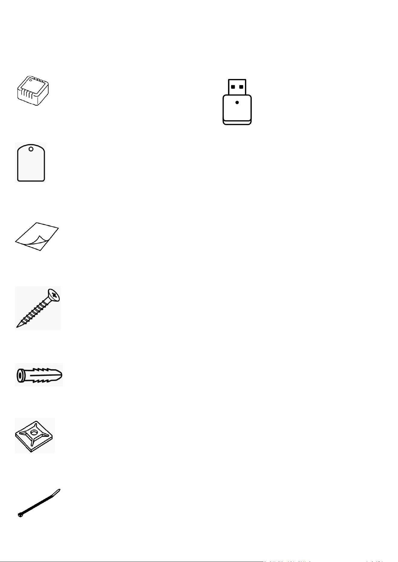
EMWS-U01
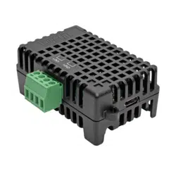
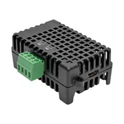
EMWS-U01(Wireless Environmental Sensor) ×1
Metal Plate ×1
Double-sided Adhesive × 2
Flat Head Screw × 2
Plastic Expansion Anchor × 2
Self-Adhesive Tie Mount x 2
Cable Tie × 2
Serial number sticker x1
EMWD-U01
EMWD-U01 (Wireless USB Dongle) x1
Serial number sticker x1

Specification
Overview
The wireless environmental sensor (EMWS-U01) along with the wireless USB dongle (EMWD-U01) provide most Switched
and Monitored PDUs to monitor the temperature and humidity of a server closet and/or data center in a wireless way.
Users can establish thresholds that will automatically notify users when an event has occurred via email, SMS, SNMP traps,
and Syslog.
This product is professional equipment intended for use in controlled environments.
EMWS-U01
Battery
CR2477
Battery Life
3–5 years Typical*
Measurement Range and Accuracy
Temperature
-4°F to 131°F with accuracy ± 0.9°F
-20°C to 55°C with accuracy ± 0.5°C
Humidity
10-90 RH with accuracy ± 2%
Communication
Wireless Radio
Frequency Radio Band
2.4 GHz
Physical
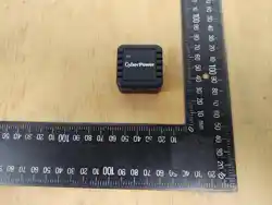
Dimensions (L x W x H)
1.46 x 1.46 x 0.79 inches/
37 x 37 x 20 mm
Weight
TBC.
Safety Approvals
FCC Class A, CE
*Under room temperature and normal use.
EMWD-U01
Power Consumption
120 mW
Communication
Connection Port
USB Type A (2.0)
Wireless Radio
Frequency Radio Band
2.4 GHz
Physical
Dimensions (L x W x H)
0.30 × 0.59 × 1.16 inches/
7.6 x 15 x 29.4 mm
Weight
TBC.
Safety Approvals
FCC Class A, CE

Installation Guide
EMWS-U01
Method 1: Cable Tie Mounting
Step 1. Position the sensor against the desired location on the rack or PDU.
Step 2. Pass a cable tie through the mounting holes on the sensor and secure it around the rack post or PDU frame.
Or, to further use self-adhesive tie mount and let cable tie pass through sensor’s mounting hole and the tie mount’s
hole.
Step 3. Tighten the cable tie to hold the sensor in place.
Method 2: Magnet Mounting
Step 1. Clean the metal surface on the rack or PDU where the sensor will be installed.
Or, to use doble-side adhesive to stick metal plate onto where the sensor will be installed.
Or, to use flat screw with plastic expansion anchor drilling and fix metal plate to where the sensor will be installed.
Step 2. Place the sensor back directly against the metal surface. The built-in magnets will hold it in place.
Step 3. Ensure the sensor is securely attached and oriented for accurate temperature measurement.
NOTE: Using flat screw with plastic expansion anchor drilling and fix metal plate have metal surfaces on a wall.
Method 3: Fixed Mounting
Step 1. Drill a hole on the rack or mounting surface compatible with the included anchor and insert the anchor.
Step 2. Insert and tighten the screw, leaving enough exposed to hang or attach the sensor.
Step 3. Mount the sensor vertically.
EMWD-U01
Step 1: Insert the EMWD-U01 into a USB port on the PDU.
Step 2: Ensure the dongle is securely connected and recognized by the PDU.
The EMWD-U01 is compatible only with supported devices and is not supported on Windows systems.
Manufacturer ensuring that the RF parameters of the device cannot be operated outside its authorization for operation.

Conformance Approvals
FCC Statement
This device complies with Part 15 of the FCC Rules. Operation is subject to the following two conditions:
1. This device may not cause harmful interference, and
2. This device must accept any interference received, including interference that may cause undesired operation.
NOTE: This equipment has been tested and found to comply with the limits for a Class A digital device, pursuant to part 15
of the FCC Rules. These limits are designed to provide reasonable protection against harmful interference when the
equipment is operated in a commercial environment. This equipment generates, uses, and can radiate radio frequency
energy and, if not installed and used in accordance with the instruction manual, may cause harmful interference to radio
communications. Operation of this equipment in a residential area is likely to cause harmful interference in which case the
user will be required to correct the interference at his own expense.
If this equipment does cause harmful interference to radio or television reception, which can be determined by turning the
equipment off and on, the user is encouraged to try to correct the interference by one or more of the following measures:
• Reorient or relocate the receiving antenna.
• Increase the separation between the equipment and receiver.
• Connect the equipment into an outlet on a circuit different from that to which the receiver is connected.
• Consult the dealer or an experienced radio/TV technician for help.
Note: This equipment has been tested and found to comply with the limits for a Class A digital device, pursuant to part 15 of
the FCC Rules. These limits are designed to provide reasonable protection against harmful interference when the equipment
is operated in a commercial environment. This equipment generates, uses, and can radiate radio frequency energy and, if
not installed and used in accordance with the instruction manual, may cause harmful interference to radio communications.
Operation of this equipment in a residential area is likely to cause harmful interference in which case the user will be
required to correct the interference at his own expense.
Warning: Changes or modifications not expressly approved by the party responsible for compliance could void the user’s
authority to operate the equipment.
FCC Radiation Exposure Statement
The available scientific evidence does not show that any health problems are associated with using low power wireless
devices. There is no proof, however, that these low power wireless devices are absolutely safe.
Low power Wireless devices emit low levels of radio frequency energy (RF) in the microwave range while being used.
Whereas high levels of RF can produce health effects (by heating tissue), exposure to low level RF that does not produce
heating effects causes no known adverse health effects.
Many studies of low level RF exposures have not found any biological effects. Some studies have suggested that some
biological effects might occur, but such findings have not been confirmed by additional research.
This device have been tested and found to comply with FCC/IC radiation exposure limits set forth for an uncontrolled
environment and meets the FCC radio frequency (RF) Exposure Guidelines in Supplement C to OET65 and RSS-102 of the IC
radio frequency (RF) Exposure rules.
Industry Canada Statement
This device complies with Industry Canada licence-exempt RSS 247 standard. Operation is subject to the following two
conditions:
1. This device may not cause interference, and
2. This device must accept any interference, including interference that may cause undesired operation of the device.
French Translation / Traduction française
Le présent appareil est conforme aux CNR d'Industrie Canada applicables aux appareils radio exempts de licence.
L'exploitation est autorisée aux deux conditions suivantes :
1. l'appareil ne doit pas produire de brouillage,
2. l'utilisateur de l'appareil doit accepter tout brouillage radioélectrique subi, même si le brouillage est susceptible d'en
compromettre le fonctionnement.
Canadian Compliance Statement
CAN ICES-3 (A)/NMB-3(A)
This equipment is not suitable for use in locations where children are likely to be present.
FCC/IC
Model: SNWEV001
FCC ID: 2AFG8SNWEV001
IC: 11470A-SNWEV001
Model: SNWDG001
FCC ID: 2AFG8SNWDG001
IC: 11470A-SNWDG001
NCC警語
取得審驗證明之低功率射頻器材,非經核准,公司、商號或使用者均不得擅自變更頻率、加大功率或變更原設計之
特性及功能。低功率射頻器材之使用不得影響飛航安全及干擾合法通信;經發現有干擾現象時,應立即停用,並改
善至無干擾時方得繼續使用。前述合法通信,指依電信管理法規定作業之無線電通信。低功率射頻器材須忍受合法
通信或工業、科學及醫療用電波輻射性電機設備之干擾。
本產品內含發射器模組
Troubleshooting
Problem
Solution
The PDU is not
able to acquire
Sensor/dongle ‘s
information
1. Check EMWD-U01 role.
Ensure at least one EMWD-U01 is set as Coordinator.
2. Verify installation via PDU web interface.
Confirm the EMWD-U01 is recognized and properly configured.
3. Check network joining settings.
Enable automatic joining, or manually add the EMWD-U01 or EMWS-U01
serial number to allow network access.
4. Check EMWS-U01 (wireless environmental sensor) LED.
Green LED blinking: normal operation
No green LED or red LED blinking: battery is low → replace the battery
5. Check other EMWD-U01 (wireless USB dongle) roles.
Ensure they are set as Router to join the Coordinator network