Manual 14-0302-SB Rev 0 (11/22)
$21.00
STEAM-IT ELECTRIC COUNTER
PRESSURE COOKER
MANUAL SECTION CO
IMPORTANT FOR FUTURE REFERENCE
Please complete this information and retain this
manual for the life of the equipment:
Model #:
___________________________
Serial #:
___________________________
Date Purchased:
_____________________
WARNING
Improper installation, adjustment, alteration, service or maintenance can cause property damage, injury
or death. Read the installation, operating and maintenance instructions thoroughly before installing or
servicing this equipment.
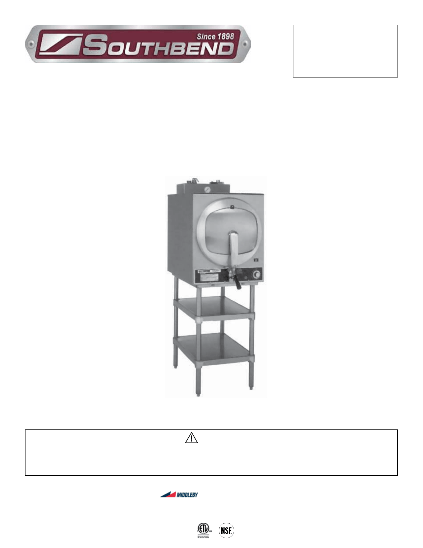
Steam-It Electric Counter
Pressure Cooker
ST-E-SB
Installation & Operation Manual
ST-E-SB
Shown on optional stand with extra shelf
SOUTHBEND STEAM
A Middleby Company
1100 Old Honeycutt Road Fuquay-Varina, North Carolina 27526 USA
www.southbendnc.com

INSTALLATION & OPERATION MANUAL 14-0302-SB REV 0 (11/22)
PAGE
2
OF 16
Steam-It Electric Counter Pressure Cooker
Your Service Agency’s Address:
Model
Serial number
Sterilizer installed by
Installation checked by
INSTALLATION & OPERATION MANUAL 14-0302-SB REV 0 (11/22)
PAGE
3
OF 16
Steam-It Electric Counter Pressure Cooker
SAFETY PRECAUTIONS
Copyright © 2022 by Southbend Steam. All rights reserved. Published in the United States of America.
Safety Precautions
WARNING
This is the safety alert symbol. It is used to alert you to potential personal injury hazards. Obey all safety messages
that follow this symbol to avoid possible injury or death.
Before installing and operating this equipment, be sure everyone involved in its operation is fully trained and aware of
precautions. Accidents and problems can be caused by failure to follow fundamental rules and precautions.
The following symbols, found throughout this manual, alert you to potentially dangerous conditions to the operator,
service personnel, or to the equipment.
CAUTION
WARNING
NOTICE
This symbol warns of immediate hazards that will result in severe injury or death.
This symbol refers to a potential hazard or unsafe practice that could result in injury or death.
This symbol refers to a potential hazard or unsafe practice that could result in injury, product
damage, or property damage.
This symbol refers to information that needs special attention or must be fully
understood, even though not dangerous.
DANGER
IMPORTANT NOTES FOR INSTALLATION AND OPERATION
WARNING
Improper installation, operation, adjustment, alteration, service or maintenance can cause property damage, injury
or death. Read the installation, operating and maintenance instructions thoroughly before installing, operating or
servicing this equipment.
NOTICE
This manual should be retained for future reference.
NOTICE
This product is intended for commercial use only. NOT FOR HOUSEHOLD USE.
WARNING
FOR YOUR SAFETY:
Do not store or use gasoline or other ammable vapors or liquids in the vicinity of this or any other appliance.
IMPORTANT
The information contained in this manual is important for the proper installation, use, and maintenance of this kettle.
Adherence to these procedures and instructions will result in satisfactory baking results and long, trouble free service.
Please read this manual carefully and retain it for future reference.
ERRORS: Descriptive, typographic or pictorial errors are subject to correction. Specications are subject to change
without notice.

INSTALLATION & OPERATION MANUAL 14-0302-SB REV 0 (11/22)
PAGE
4
OF 16
Steam-It Electric Counter Pressure Cooker
RETAIN THIS MANUAL FOR FUTURE REFERENCE.
Table of Contents
Important Notes For Installation and Operation .................................................................... 3
Service Connections ............................................................................................................. 5
Installation ............................................................................................................................. 6
Operation .............................................................................................................................. 9
Maintenance ......................................................................................................................... 14
Table of Contents
INSTALLATION & OPERATION MANUAL 14-0302-SB REV 0 (11/22)
PAGE
5
OF 16
Steam-It Electric Counter Pressure Cooker
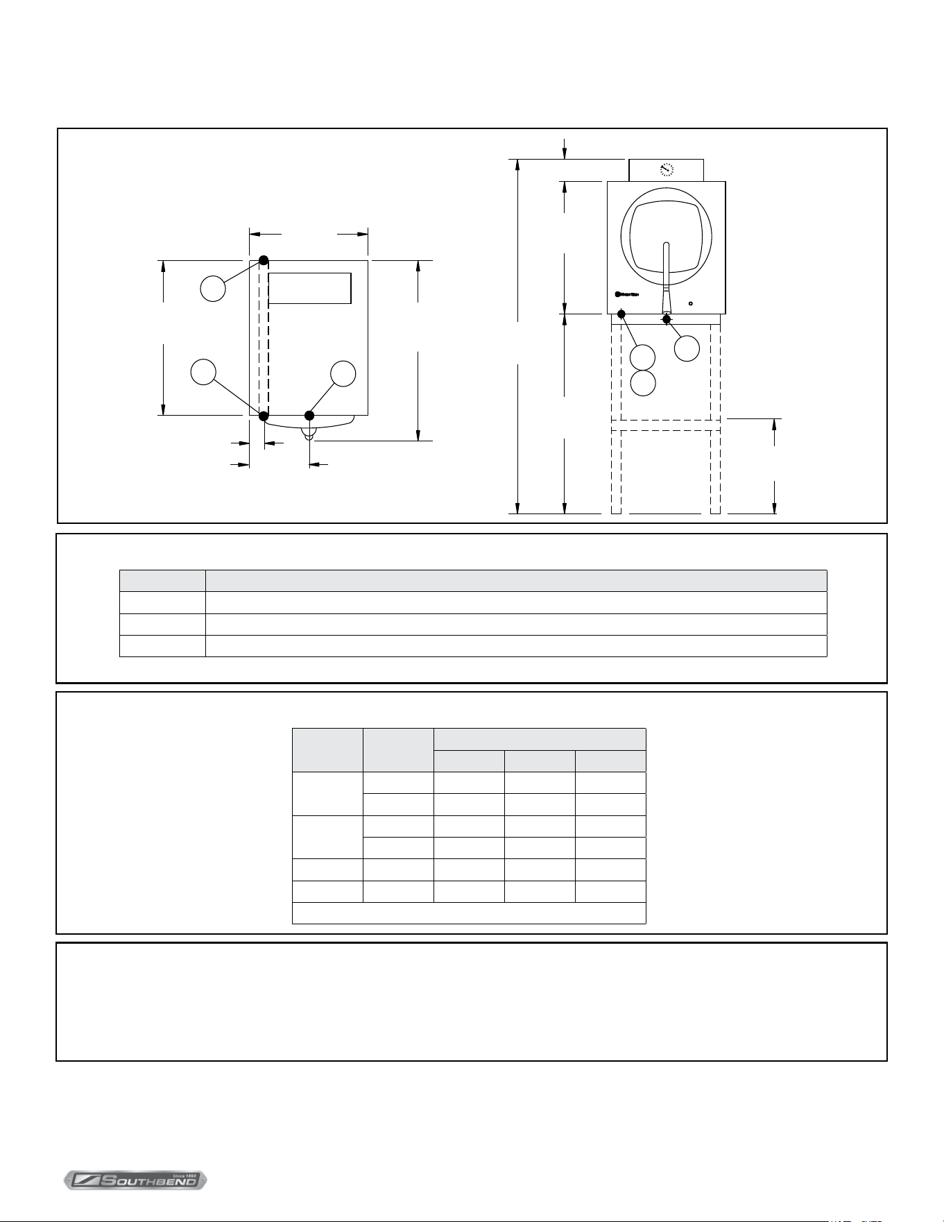
DIMENSIONS ARE IN INCHES [MM]
18.75 [476]
EC
25
[636]
3.25 [83]
D
31.5 [800]
door handle
to rear
9.38 [240]
Conduit
EP
STEAM-IT
EC
3.25 [83]
23
[584]
53.25
[1353]
27
[686]
D
12 [305]
Approx.
STAND
OPTIONAL
EP
DIMENSIONS ARE IN INCHES [MM]
18.75 [476]
EC
25
[636]
3.25 [83]
D
31.5 [800]
door handle
to rear
9.38 [240]
Conduit
EP
STEAM-IT
EC
3.25 [83]
23
[584]
53.25
[1353]
27
[686]
D
12 [305]
Approx.
STAND
OPTIONAL
EP
Service Connections
Service Connections
As continued product improvement is a policy of Southbend Steam, specications are subject to change without notice.
DIMENSIONS ARE IN INCHES [MM]
WATER SUPPLY AND DRAIN SPECIFICATIONS
Good quality water feed is the responsibility of the owner. Water quality must be within the following general guidelines.
TDS: 40-125 ppm Hardness: 35-100 ppm pH: 7.0 - 8.5 Silica: <13 ppm Chlorides: <25 ppm Chlorine: <0.2 ppm Chloramine: <0.2 ppm
The best defense against poor water quality is a water treatment system designed to meet your water quality conditions.
Appliance to be installed with backflow protection according to federal, state or local codes.
The manufacturer reserves the right to modify materials and specifications without notice.
ELECTRICAL CHARACTERISTICS
Volts Phase
AMPS
9kW 12kW 12.5kW
208
1 43 - -
3 25 - -
240
1 - 50 -
3 - 29 -
440 3 - 16 -
480 3 - - 16
Details of other electrical systems available upon request.
SERVICE CONNECTIONS
SYMBOL DESCRIPTION
EC Electrical Connection - Connection for incoming power supply wires on terminal block
EP Power Supply - 1-1/4” threaded access hole for power supply wires. Use wire suitable for at least 90°C. Nominal amps per line.
D Drain - 1/2” 13mm O.D. tubing. Air break required for drain connection supplied by others

INSTALLATION & OPERATION MANUAL 14-0302-SB REV 0 (11/22)
PAGE
6
OF 16
Steam-It Electric Counter Pressure CookerInstallation
Installation
The Southbend Steam Steam-it model ST-E-SB Electrically Operated Pressure Cooker.
Description
Steam-It shall have a 3/16” (5mm) aluminum welded seamless cooking compartment. Exterior nish shall be
stainless steel. Door shall be self-sealing inside type which can’t be opened under pressure. Door is 12 gauge
stainless steel, removable for cleaning without tools.
Door gasket is a one piece mold, replaceable without tools or cement.
Cooking compartment has a capacity of (3) 12” x 20” x 2 1/2” or (2) 12” x 20” 4” pans. Removable pan supports are
included. Cooking cycle is controlled by an automatic timer that will shut o and exhaust steam and condensate at
end of cooking cycle. Unit includes 0-60 minute timer, a safety valve, steam pressure gauge, and will be completely
serviceable from the front.
Installation
Set steam-it on counter, using 4” (102mm) legs provided with unit or an optional stainless steel stand with
under-shelf. If your steam-it includes a water-cooled exhaust condenser, we recommend the use of the steam-it
stand, part number 95-6060. First, level unit in place. Then adjust front legs to pitch the unit forward 1/4” (6mm)
to insure positive drainage of the cylinder.
Electrical
Connect to proper electrical supply box and disconnect switch as shown on one of the following schematic
diagrams 208 or 230 volts, single or three phase. Connection is located behind the terminal box cover at the lower
left side of unit. Whether the supply current is 208 volt or 240 volt, single or three phase, all control circuits are 120
volts. In order to accomplish this connection, a current-carrying grounded neutral must be provided. Thus, a three
phase system must be 4-wires and a single phase system must be 3-wires. If a current-carrying grounded neutral
is not available from the power source, a separate 120 volt circuit must be run. Most electrical codes require, and
we recommend, that a separate disconnect switch be located within sight of the sterilizer. When separate 120 volt
control circuit must be run, this must also be part of the disconnect box assembly.
Outside Venting
Connect 1/2” (13mm) nominal tubing exhaust to outside vent connection located on the top of the control housing.
IMPORTANT
Exhaust line must be vented to the outside to eliminate the exhausted steam and the accompanying noise from
entering the room. Use 1/2” (13mm) copper tubing or suitable alternate. Length of the line should not exceed 15 feet
(4.5 meters) and should have a minimum of bends. The line should slope downward after leaving the sterilizer in order
to insure condensate drainage.
Water-Cooled Exhaust Condenser
If outside venting is not possible, an optional water-cooled condenser is available for connection to an open drain. For
details of the installation on the ST-E-SB, see page 5.
Recording Thermometer
If a recording thermometer is provided, see installations with the thermometer for installation.
INSTALLATION & OPERATION MANUAL 14-0302-SB REV 0 (11/22)
PAGE
7
OF 16
Steam-It Electric Counter Pressure Cooker Installation
WARNING
Do not open drain valve while unit is operating. Premature opening may result in scalding of operator.
CAUTION
Before connecting water to this unit, have water supply analyzed to make sure hardness is no greater than 2.0
grains and pH level is within the range of 7.0-8.5. Water which fails to meet these standards should be treated by
installation of a water conditioner. EQUIPMENT FAILURE CAUSED BY INADEQUATE WATER QUALITY IS NOT
COVERED UNDER WARRANTY.
NOTICE
Details of other electrical systems available upon request. Consult Factory.
Tray Supports
Install side tray supports. Tray supports are attached by means of key-hole clearance slots which are slipped over studs
located on the sides of the chamber. Install so that open end of the channel sides faces the sides of the unit.
Baffle Installation
To insure maximum drying of packs, a bae is supplied with your ST-E-SB. Place perforated splash bae in bottom of the
sterilizing chamber. Install small bae with no perforation at the rear of the upper tray support channel.
Operation Check
To check for proper operation of unit:
1. Close drain valve by turning handle clockwise.
2. Fill chamber with 4 to 6 quarts (3.7 to 5.6 liters) of ordinary tap water. DO NOT USE DISTILLED WATER.
3. Close chamber door.
4. Set exhaust selector to INSTRUMENTS AND PACKS (fast exhaust) or LIQUIDS (slow exhaust).
5. Set timer to 15 minutes. Cycle will go to completion automatically.
NOTICE
Cycle timer will not start until sterilizing temperature is obtained.
Operation Shall Be By:
Direct steam at 15 PSI (1kg/cm2). Minimum BHP required: 1 BHP
INSTALLATION & OPERATION MANUAL 14-0302-SB REV 0 (11/22)
PAGE
8
OF 16
Steam-It Electric Counter Pressure Cooker
Assembly of Legs or Stand
Tools Required
• 1 3/16’ Allen Wrench • 1 One foot ruler • 1 Screw Driver
Remove all parts from box
Stand
Item Quantity
Legs (27”) 4
Leg Tops 4
Cap Brackets 4
Lock Washers 8
Flat Washers 8
Round Head Screws (1/4-20) 8
Shelf 1
Set Screw (In Shelf) 4
Stand
Item Quantity
Legs (4”) 4
Leg Tops 4
Cap Brackets 4
Lock Washers 8
Flat Washers 8
Round Head Screws (1/4-20) 8
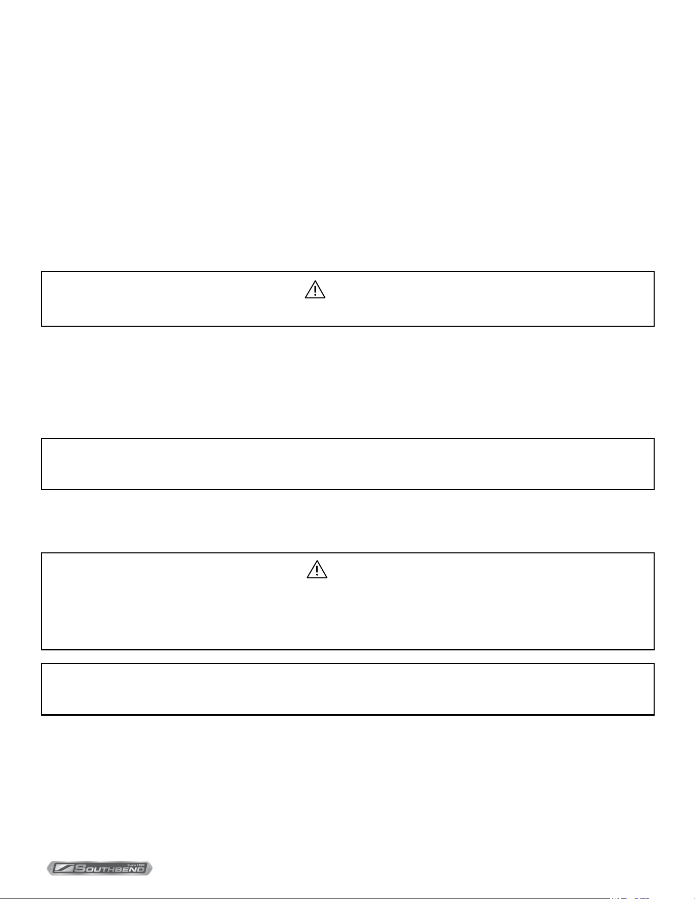
Assemble Unit As Follows
Installation
NOTICE
For assembly to stand follow steps 1 through 9.
For assembly on legs follow steps 4 through 9.
1. Insert four legs in shelf from top down (1).
2. Measure 12” from bottom of leg to top of shelf in all four positions (2).
3. Tighten set screw securely once shelf is level.
4. Screw four leg tops on four legs (with or without shelf) until they are all the way down.
5. Ascertain that tops on all leg tops are equidistant from the oor or counter.
6. Screw cap bracket (6) on to threaded tting in leg top.
IMPORTANT
Be sure threaded holes are all on the outside.
7. Tip steam-it on it’s back.
8. Place stand on legs in frame (7) of steam-it (8), making sure that slot (9) in frame matches holes in cap bracket (6).
9. Insert lock washer and then at washer (10) on round headed screw (11) and insert loosely in slot and threaded hole
(8 positions). Tighten all screws (11).
Figure 1
INSTALLATION & OPERATION MANUAL 14-0302-SB REV 0 (11/22)
PAGE
9
OF 16
Steam-It Electric Counter Pressure Cooker Operation
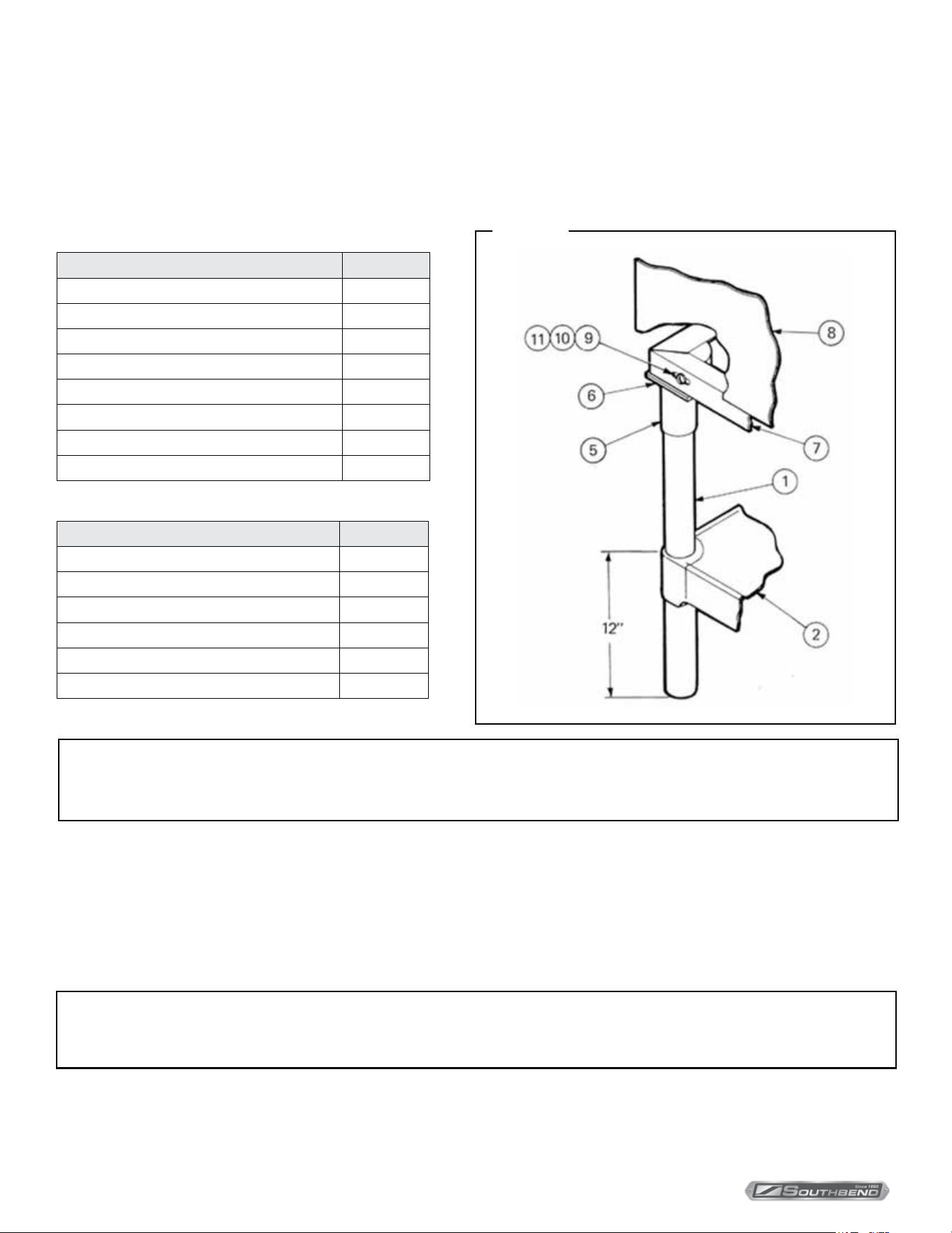
Operation
Steamer Control
Buzzer
The function of the buzzer is to signify to the operator that the cycle of cooking has been terminated. The buzzer is
mounted on a bracket which is positioned at the front of the unit just under the front removable panel. The buzzer
electrical circuit is controlled by the timer. When the timer reaches zero the circuit will be completed and the buzzer will
continue to sound until the timer knob is turned to the o position.
Pilot Light
The pilot light is located at the lower right front of the panel. This unit is wired to operate when the heating elements are
on. The circuit will be broken when the timer returns to the “0” position. Thus, when the pilot light is on and o it signals
that the heating elements are cycling on and o to maintain cooking pressure in the cooking chamber.
Timer
The timer, located at the lower right front of the Steam-It provides a means of manual control. The Steam-It put into
an automatic cycle of cooking with the setting of the timer to any of its calibrated periods of cooking. Its timing cycle
however, is automatically delayed by the timer control switch until free-venting has occurred and a cylinder pressure
build up to 10 PSI has been reached.
Steam Pressure Gauge
Located at the top rear of the Steam-It and mounted into the forward face of the ue for visibility, the steam pressure
gauge registers the pressure within the Steam-It cooking chamber. To replace this unit it is necessary to disconnect the
3/16” copper tube connector and remove the two nuts holding the gauge framework in place.
Figure 2
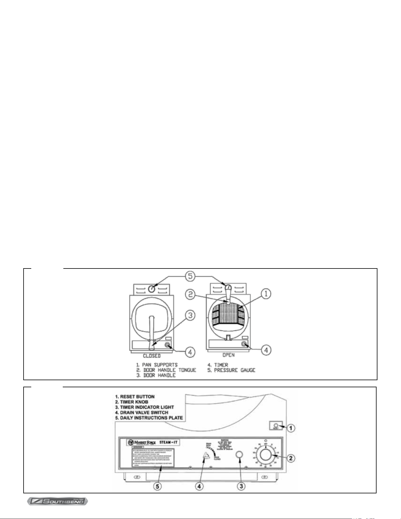
Figure 3
INSTALLATION & OPERATION MANUAL 14-0302-SB REV 0 (11/22)
PAGE
10
OF 16
Steam-It Electric Counter Pressure CookerOperation
Preliminary Procedures
1. Ensure that electric supply is connected and operating at unit.
2. Close drain valve by turning valve handle clockwise.
3. Hang pan supports on pan support studs (cylinder side walls). The horizontal key hole on the support be at rear of
compartment and vertical key hole near front.
4. Pour approximately 6 quarts of water directly into steam-it cylinder.
WARNING
Do not open drain valve while unit is operating. Premature opening may result in scalding of operator.
CAUTION
A high degree of mineral salts in water can cause pitting of cooking compartment unless above directions (see note
above) are followed; the cooking compartment thoroughly cleaned and drained each night; and the door left open.
Also, do not scour cylinder with abrasive cleanser.
NOTICE
In geographical locations where high amount of lime and alkaline (salt-lime substance) deposits are present in water
supply, add two tablespoons of vinegar directly into the 6 quarts of water prior to the start of cooking cycle. If more
water is added to maintain required level, an occasional tablespoon of vinegar may be added as well, in order to
compensate for new mineral deposits in fresh water.
Preheating
Before each initial operation of cooker and at any time when
compartment is cold, a 5 to 8 minute preheating period is
required. To preheat cooking compartment, proceed as
follows:
1. Close door and lock in position by placing the door
handle tongue under roller on drain casting. Press
downward on door handle until door is secured.
2. Set 60 minute timer to 5 minutes by turning past 10 and
back to 5 to ensure proper setting. Indicator light will
come on.
3. When preheating is ended and buzzer sounds, turn
timer to o and allow pressure to return to zero PSI on
pressure gauge.
4. Open compartment door slightly by pulling up on latch
handle to allow remaining vapors to escape before
raising door to full open position.
WARNING
Do not leave hand on handle while excess vapor is escaping. Scalding of hand may result.
Figure 4
Start-up and Preheating

INSTALLATION & OPERATION MANUAL 14-0302-SB REV 0 (11/22)
PAGE
11
OF 16
Steam-It Electric Counter Pressure Cooker Operation
After preheating cycle is completed, compartment may be loaded for cooking. Proceed as follows:
1. Carefully slide cooking pans onto pan supports.
2. Close door and lock in position (see step 1 under preheating).
3. Set timer to desired cooking time by turning timer past desired setting and then back.
NOTICE
Timer will not start until unit is at a minimum of 9 PSI (0.6kg/cm2) as indicated on pressure gauge.
4. At end of cooking cycle, steam will automatically exhaust. When pressure reaches 0 PSI on pressure gauge, door can
be released by pulling on door latch handle (see step 4 under preheating, including warning). Allow a few seconds for
remaining vapor to leave cylinder before completely opening the door. To stop buzzer, turn to OFF.
5. Remove cooked food, add desired seasoning, and transfer to serving area.
NOTICE
Perforated pans, if they are to be transferred to serving ares, should be underlined with solid pans.
6. Before starting another cycle, water should be at six quart level.
NOTICE
If unit is operated with an insucient amount of water, the low water cut-o will shut down the unit. With the replacement
of water into cooking cylinder, the unit will be operative again after the low water cut-o reset button is pressed. If unit
does not start after pressing reset button, more time will be needed before reset button starts unit. Should a cooking
cycle be interrupted by the low water cut-o, the food in the process of cooking will be aected. Proper compensation
will have to be made for cooking performed and with proper amount of water in cooking cylinder, a new cycle
determined and set to complete cooking process.
NOTICE
If strong avored foods such as seafood have been cooked, cylinder should be drained (by turning drain valve handle
counterclockwise), cleaned and ushed, and fresh supply of water added for the next cooking cycle.
NOTICE
If is normal on start-up or after prolonged idleness for small amounts of steam to leak between door and cylinder. This
leakage will often cease after the rst or second cycle. However, if steam continues to escapes around door edges
while pressure is building up on the third cycle, door seal adjustment can usually be made.
7. Clean unit thoroughly at end of each cooking day. Ensure that cylinder is left dry and door open (refer to cleaning and
preventive maintenance).
Cooking

INSTALLATION & OPERATION MANUAL 14-0302-SB REV 0 (11/22)
PAGE
12
OF 16
Steam-It Electric Counter Pressure CookerOperationOperation
Item
Approx. Wt.
Per Pan
Recommended
Pan Size, 12” × 20”
Perforated
Number
of Pans
Timer Settings
in Minutes
Approx. No.
Cooked 2 oz. (55g)
Servings Per Pan*
Lbs Kg Inche mm
VEGETABLES, FROZEN - DEFROSTED
Asparagus Spears 5 2.3 2 1/2 65
1
2-3
7-8
8-10
23-25
Beans, Green Regular 5 2.3 2 1/2 65
1
2-3
7-8
8-10
23-25
Beans, Green French Cut 5 2.3 2 1/2 65
1
2-3
7-9
9-10
23-25
Beans, Lima 5 2.3 2 1/2 65
1
2-3
6-7
7-8
23-25
Broccoli 5 2.3 2 1/2 65
1
2-3
5-6
6-7
23-25
Brussel,Sprouts 5 2.3 2 1/2 65
1
2-3
6-7
8-10
18-20
Carrots 5 2.3 2 1/2 65
1
2-3
5-6
7-9
23-25
Cauliower 5 2.3 2 1/2 65
1
2-3
7-8
8-10
23-25
Corn 5 2.3 2 1/2 65
1
2-3
5-6
7-8
23-25
Peas 5 2.3 2 1/2 65
1
2-3
2-3
4-5
23-25
VEGETABLES, FRESH
Beans, Wax Green 6 2.7 2 1/2 65
1
2-3
4-6
7-8
30-35
Broccoli, 1/2-3/4” Stalk 6 2.7 2 1/2 65
1
2-3
4-5
5-6
25-30
Cabbage, Cored - 1/4 1/6 of head 5 2.3 2 1/2 65
1
2-3
7-9
10-12
12-20
Carrots, Sliced 9 4.1 2 1/2 65
1
2-3
6-8
10-12
35-40
Cauliower 6 2.7 2 1/2 65
1
2-3
5-6
6-8
30-35
Corn on Cob, Husked 1 Dozen 2 1/2” 65
1
2-3
5-6
6-8
12
Potatoes, French Fry 10 4.5 2 1/2 65
1
2-3
7-9
10-12
50
Potatoes, Regular Cut 10 4.5 2 1/2 65
1
2-3
13-15
17-19
50
Spinach, Cut and Cleaned 3 1.4 4 100
1
2-3
1-2
2-3
4 oz (110g)
10-12
Squash, Summer, 1” Slices 7 3.2 2 1/2 65
1
2-3
5-7
8-10
30-35
Squash, Winter, diced 9 4.1 2 1/2 100
1
2-3
7-9
10-12
30-35
Turnip, diced 5 2.3 2 1/2 65
1
2-3
10-15
15-20
4 oz (110g)
20-25
* All portions are equivalent to approximately 1/2 cup cooked.
Suggested Cook Times

INSTALLATION & OPERATION MANUAL 14-0302-SB REV 0 (11/22)
PAGE
13
OF 16
Steam-It Electric Counter Pressure Cooker OperationOperation
Item
Approx.
Wt. Per Pan
Recommended
Pan Size, 12” × 20”
Perforated
Number
of Pans
Timer Settings
in Minutes
Approx. No.
Cooked 2 oz. (55g)
Servings Per Pan*
VEGETABLES, CANNED
Canned, Vegetables 5 2.3 2 1/2 65
1
2-3
4-5
5-7
26-30
MEAT - POULTRY - FISH
Chicken, cut-up, breaded 2 1/2 65
1
2-3
10-15
15-20
15-20 Protein
Chicken, Whole 4 100
1
2-3
35-40
45-50
25-30 Protein
Fish, Fillets 2 1/2 65
1
2-3
7-8
8-10
12-15 Protein
Fowl, Whole 4 100
1
2-3
40-45
45-60
20-25 Protein
Frankforts 2 1/2 65
1
2-3
1-2
2-3
35-40 Protein
Hamburgers, 3 oz (85g) 2 1/2 65
1
2-3
8-10
12-15
20-25 Protein
Lobster 1# size (450g) 2 1/2 65
1
2-3
3-6
5-8
10-1# (150mm)
Meatballs ** 1 oz. (28g) 2 1/2 65
1
2-3
15-17
18-20
20-25 Protein
Meatloaf ** 2 1/2 65
1
2-3
25-30
30-35
50-60 Protein
Pork Chops 4 oz. (114g) with bone 2 1/2 65
1
2-3
15-20
20-25
24 Protein
Sausages, 10 per lb. (45g) 2 1/2 65
1
2-3
14-16
17-19
18-20 Protein
Turkey, on Carcass 4 100 1 75-90 50-60 Protein
Turkey, o Carcass 2 1/2 65
1
2
40-45
45-50
55-65 Protein
MISCELLANEOUS
Eggs, out of shell 4 Dozen 2 1/2 65
1
2-3
3
3-4
48
48
Rice, 1 gal. water (3.78 liters) 4 1.8 4 100
1
2
17-20
21-25
60 3 oz. (85g)
Portions
Spaghetti, 1.5-2 gal. Water (5.7-7.6 liters) 3 1.4 4 100
1
2-3
17-20
21-25
40-45 4 oz. (110g)
Portions
* All portions are equivalent to approximately 1/2 cup cooked.
** Raw weight for meatballs and meatloaf includes hamburg and extenders and yields 2 oz. (55g) protein plus extenders for 3 oz. (85g) total portion.
INSTALLATION & OPERATION MANUAL 14-0302-SB REV 0 (11/22)
PAGE
14
OF 16
Steam-It Electric Counter Pressure Cooker
Maintenance
Cleaning and Preventive Maintenance
WARNING
Do not hose down unit as it contains electrical components.
The Southbend Steam Steam-it Must be cleaned every day as follows:
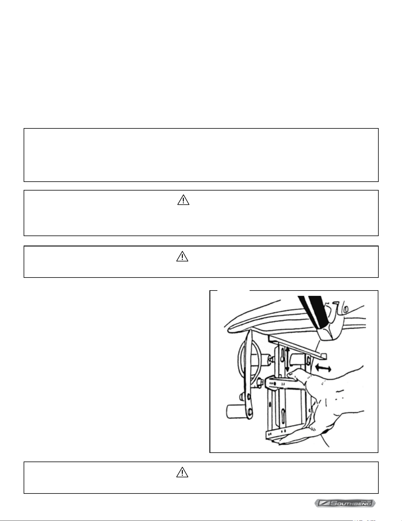
Daily
1. Remove pan supports by lifting front up and o stud. Pull back of pan
support forward and o stud. Wash with mild detergent and water. Rinse
and dry thoroughly.
2. Wash interior of Steam-It thoroughly with mild detergent and water (A).
Rinse and dry thoroughly. Cylinder is aluminum and can pit if not cleaned
properly. Be sure to wash drain plug area if you model is so equipped (B).
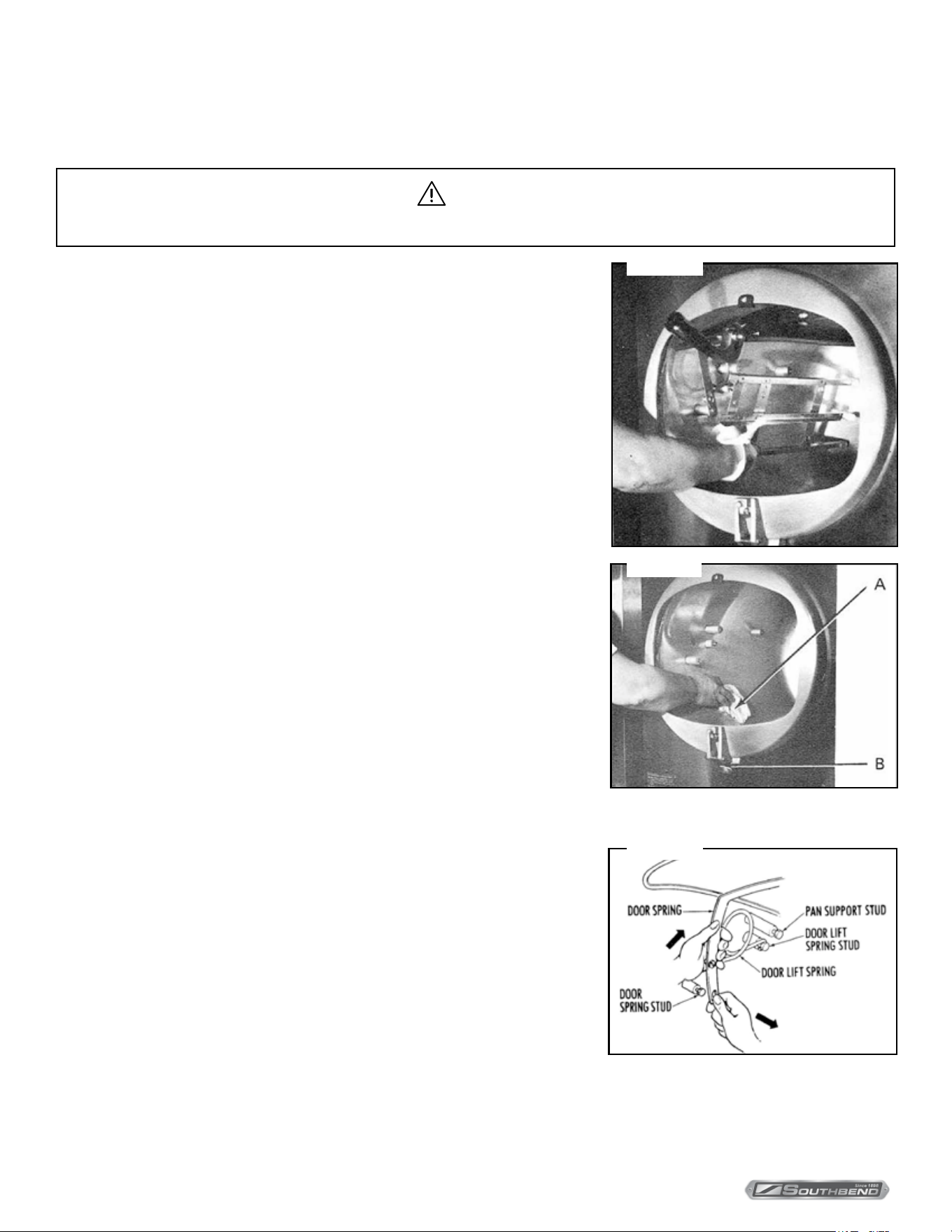
Weekly
1. Remove door. (Follow these instructions carefully as the clearances
through the portal are close and much confusion can result if not removed
in the sequence described below).
2. Raise the door to a fully open position and disengage the door spring from
each of the door spring studs. Do this by counter-acting the force of the
door lift spring with one hand while working the end of the door spring o
the door assembly with the free hand. Do this on both sides of the door
assembly.
3. When the ends of the door spring have been completely freed from their
respective door spring studs, the door lift springs on either side of the door
assembly can easily be slipped o their studs.
Figure 5
Figure 6
Figure 7
Maintenance
INSTALLATION & OPERATION MANUAL 14-0302-SB REV 0 (11/22)
PAGE
15
OF 16
Steam-It Electric Counter Pressure Cooker
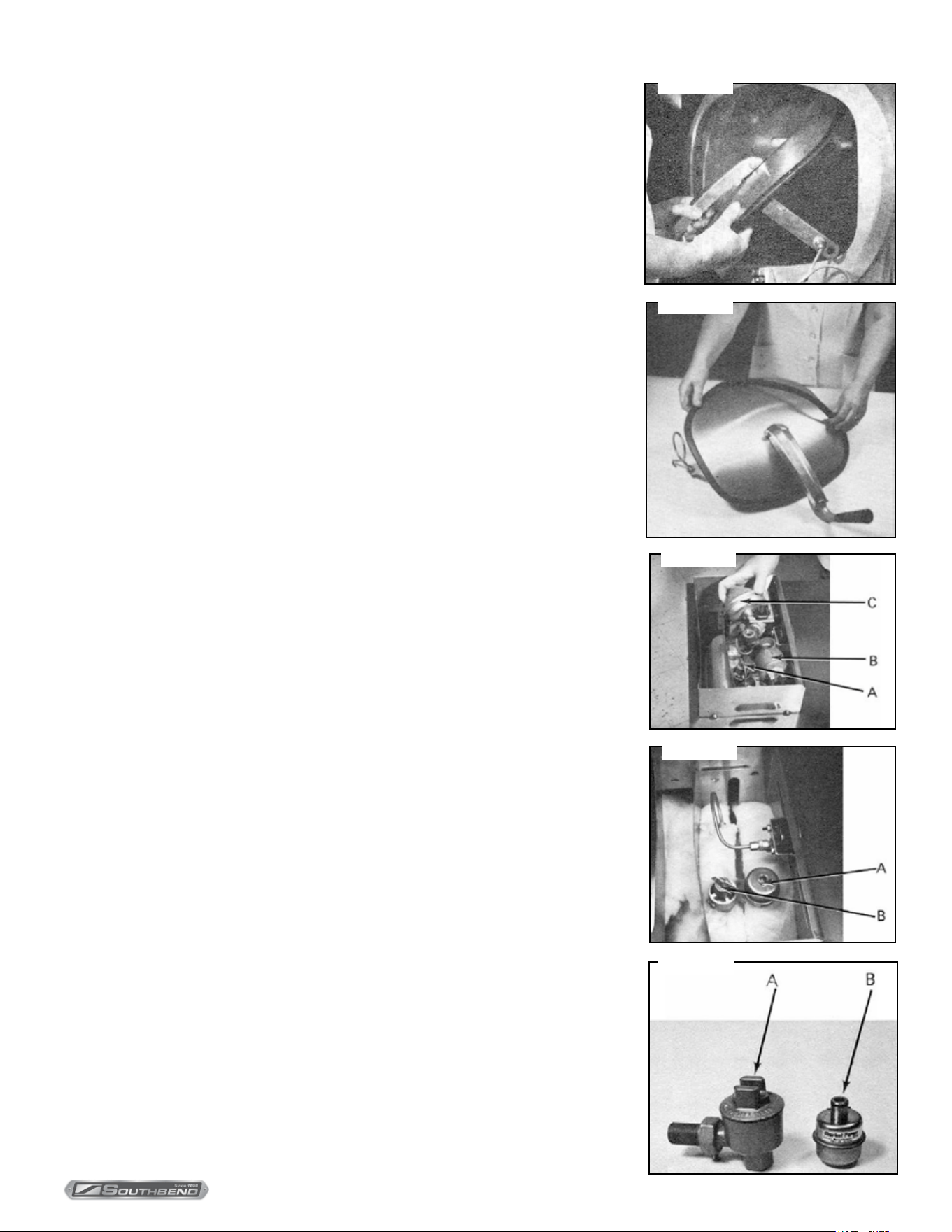
4. Rotate the entire door assembly out through the door opening. Pass the
door handle through the opening rst and then one end of the door spring as
shown. The remainder of the door assembly will then pass through the door
opening quite easily.
5. Gasket should be removed and washed when necessary. Replace gasket only
when door has been removed. Replace door and pan supports after unit has
been thoroughly cleaned.
6. Check safety valve (A). Lift handle on valve when Steam-It is under pressure.
Steam should escape. (Note: Dirty water may escape for a few seconds, but
then steam should ow freely).
7. Steam trap (B) should rst allow air to escape and then slowly close as all air
is forced out of the compartment. The sound of air escaping is quite noisy but
subsides once steam pressure is built up and cooking takes place. If steam
trap does not close it should be replaced.
8. Exhaust silencer (C) must be cleaned by rinsing in mild detergent and water or
change whenever it becomes clogged.
9. The steam trap is shown in (A) and the safety valve is shown in (B). Inspection
and maintenance procedures are the same.
Your particular unit may be equipped with a dierent trap. Old style: (A) or new
style (B). Replacement steam traps will be of the new style.
In addition to the daily cleaning it is necessary to clean the air intakes on a weekly
basis. Air intakes provide necessary cooling air to the internal components. They
are generally located on the rear and sides of the equipment.
Figure 8
Figure 9
Figure 10
Figure 11
Figure 12
Maintenance
INSTALLATION & OPERATION MANUAL 14-0302-SB REV 0 (11/22)
PAGE
16
OF 16
Steam-It Electric Counter Pressure Cooker
ST-E-SB
Steam-It Electric Counter
Pressure Cooker
A product with the Southbend Steam name incorporates the best in durability and low maintenance. We all recognize,
however, that replacement parts and occasional professional service may be necessary to extend the useful life of this
appliance. When service is needed, contact a Southbend Steam Authorized Service Agency, or your dealer. To avoid
confusion, always refer to the model number, serial number, and type of your appliance.
SOUTHBEND STEAM
A Middleby Company
1100 Old Honeycutt Road Fuquay-Varina, North Carolina 27526 USA
www.southbendnc.com