Instruction Manual
1500RPM Generator
WARNING: Read the instructions carefully before use.


SafetyandWarning
Beforeoperationandmaintenanceforthegeneratorsets,pleasereadcarefullyaboutthismanualandmakesurea
goodunderstandingofthisoperationmanualandotherdocumentswhichattachedwiththeengine.
Correctinstallationofthegeneratorsetisthepreconditionofnormaloperation.Qualifiedsparepartsshallbeused
formaintenancetoensuregoodrunni
ngconditionandlonglifeexpectancyofthegeneratorsets.
Thegeneratorsetshallbeoperatedonly bythestaffswhohavereceivedtrainingontheoperationandtherepair
shallbemadebytheauthorizedstaffs.Operatorandmaintenancestaffshallbeclearaboutsafetyandpreventive
actionsandoperationmai
ntenanceprocedure.
The generator sets can only be started under safetyconditions. Please do not start the generator sets when any
abnormalconditionhasbeenfoundsothattoavoidaccidents.
Whenclean,maintainandrepairthegeneratorsets,pleaseshutdownthegeneratorsetandcutofftheconnection
ofnegativepolarofthebatteryordismantlebatteryconnectingcable,andplacewarninglabelattherelativeplace
so
thattoavoidaccident.
The exhaust air discharged from engine is harmful for people’s health. All of the generator sets installed indoors
shalldischargetheexhaustgastooutsidedoors.
Duringtheperiodof
generatorsetrunning,theexhaustpipeandsilencerwillgeneratehightemperature.Therefore
whenthegeneratorsetisinstalled,thesepartsneedtobecoveredwithinsulationmaterialsandbekeptfaraway
frominflammablematerials.
Pleaseensuregoodventilationandorganizedenvironmentforthe
generatorset’sinstallationroom.
Pleasedonotplaceinflammablematerialsandexplosives(liquid)neartheengine.
Smoking,sparkover,andotherfirelightingbehaviorsarenotallowedintheareawhichisclosetothebatteryand
fuelbecausethemixtureofvolatilizationfromfuelandhydrogengeneratedbybatterychargingprocesswillcause
explosion
whenitmeetssparkleornakedflame.
The generator set installation room shall be facilitated with BC and ABC fire extinguisher, and operators shall be
familiarwiththeknowledgeonhowtouseit.
Whenfan protection coverorotherprotectioncoverhasbeendetached, please do not trytostart the generator
set;andwhenthegeneratorsethastobestarted,pleasedon’tputyourhandintheareawheretheprotection
cover
ismissingormakerepairaroundtheseareas.
Please keep your palm, arm, long hair, jewelry and loose clothes far away from belt pulley,
belt and other power
transmissionparts.
Whenworkinginthegeneratorsetinstallationroom,pleasewareworkingclothes,glovesandhat.
Afterthegeneratorsetbeingstarted,pleasedon’ttrytoopenthecoveroftheradiatorbeforetheantiǦfreezefully
cooleddown,sothattoavoidsteam(hotwater)burstfort
htohurtpeople.
Please don’t swallow or let your skin contact with the harmful materials such as fuel, antiǦfreeze, lubricant and
electrolyte.Whenyouskinisspatteredwiththesekindsofliquids,pleaseuseplentyofwatertorinse.
Long time stay in high noise level environment will cause harm to your hearing. If
you have to work around the
generatorsetfrequently,you’dbetterwarethedevicetoprotectyourear.
When the generator set need to make cable connections to output power, the operation shall conform to the
condition, specification, standard related to power
distribution. Qualified cable shall be used to make power
distribution.
Whentheinstallationofgeneratorsetinvolveswithwelding,pleasedonotconnecttothegroundcircuitormake
groundingthroughgeneratorset(engine)sothattoavoidthebigcurrentgeneratedfromweldingoperationhurt
theelectricappliance,bearingandbearingbushetc.
insideofthegeneratorset.
Pleaseensurethesafetyofgeneratorsetandreliablegrounding.
Safetylabelsinformation
TRANSPORTWARNING
! Never lift the generating set by attaching to the
engine or alternator lifting lugs, instead use the
liftingpointsonthebaseframeorcanopy.
! Ensure that the lifting rigging and supporting
structure is in good condition and has a capacity
suitablefortheload.
! Keep all personnel away from the generating set
whenitissuspended.
MECHANICALWARNING
!Donotattempttooperatethegeneratingsetwith
thesafetyguardsremoved.Whilethegeneratingset
isrunningdonotattempttoreachunderoraround
the guards to do maintenance or for any other
reason.
! Keep hands, arms, long hair, loose clothing and
jewelersawayfrompulleys,beltsandothermoving
parts.
SAFEGUARDWARNING
! Generating sets that are not equipped with sound
attenuating enclosures can produce noise levels in
excess of 105 dB (A). Prolonged exposure to noise
levelsabove85dB(A)ishazardoustohearing.
! Wear protective clothing including gloves and hat
whenworkingaroundthegeneratingset.
!Ifequippedkeepaccessdoorsonenclosuresclosed
andlockedwhennotrequi
redtobeopen.
!
Avoidcontactwithhotoil,hotcoolant,hotexhaust
gases,hotsurf acesandsharpedgesandcorners.
CHEMICALWARNING
!Ensure that the generating set room is properly
ventilated.
!Keep the room, the floor and the generating set
clean. When spills of fuel, oil, battery electrolyte or
coolant occur, they should be cleaned up
immediately.
!Neverstoreflammableliquidsneartheengine.
!Do not smoke or allow sparks, flames or other
sources of ignition around fue
l or batteries. Fuel
vapors are explosive. Hydrogen gas generated by
chargingbatteriesisalsoexplosive.
!Neverstoreflammableliquidsneartheengine.
!Do not smoke or allow sparks, flames or other
sources of ignition around fuel or batteries. Fuel
vapors are explosive. Hydrogen gas generated by
chargingbatteriesisalsoexplosive.
ELECTRICALWARNING
! The generating set should be shutdown with the
batterynegative (Ǧ) terminaldisconnected prior to
attempting to connect or disconnect load
connections.
! Do not attempt to connect or disconnect load
connections while standing in water or on wet or
soggyground.
!Makesureconnectgeneratorsettoearth.
! Replace the generating set terminal box cover as
soon as connection or disconnection of the load
cables is complete. Do not operate the generating
setwithoutthecover
securelyinplace.
! Connect the generating set only to loads and/ or
electrical systems that are compatible with its
electrical characteristics and that are wit
hin its
ratedcapacity
.
! Keep all electrical equipment clean and dry.
Replace any
wiring where the insulationis cracked,
cut, abraded or otherwise degraded. Replace
terminals that are worn, discolored or corroded.
Keepterminalscleanandtight.
! Do not touch electrically energized parts of the
generating set and/or interconnecting cables or
conductors wi
th any part of the body or with any
noninsulatedconductiveobject.

Table of Contents
1 General Introduction
1.1 Brief Introduction……………………………………1
1.2 Generator Set Main Parts Specifications…………1
1.4 Alternator ……………………………………………1
1.3 Diesel Engine ……………………………………… 1
1.4 Alternator …………………… …………………… 1
1.5 Cooling System ……………………………………2
1.6 Electrical System …………………………………2
1.7 Coupling ……………………………………………2
1.8 Fuel Tank and Base Frame ………………………2
1.9 Control Panel ………………………………………2
1.10 Optional for Canopy Generator Set ……………2
1.11 Others ……………………………………………3
2 Installation
2.1 General Outline ……………………………………4
2.2 Transportation ……………………………………4
2.3 Design for Foundation ……………………………4
2.4 Design for Generator Set Working Room ………4
2.5 Installation of Generator Set………………………5
2.6 Cooling system ……………………………………7
2.7 Lubricant system …………………………………8
2.8 Fuel system…………………………………………8
2.9 Battery ……………………………………………10
2.10 Electrical Connection……………………………11
2.11 Power distribution system………………………11
3 Operation
3.1 Inspect Before Operation ………………………12
3.2 Generator set’s running …………………………12
3.3 After Running ……………………………………13
3.4 Record for running ………………………………13
3.5 Matters need attention …………………………13
3.6 Operation for control system ………………..14-16
3.7 ATS control panel …………………………..17-18
4 Maintenance
4.1 General outline……………………………………19
4.2 Engine ……………………………………………19
4.3 Alternator …………………………………………20
4.4 Control panel ……………………………………20
4.5 Start battery ……………………………………...20
4.6 Maintenance record ……………………………20
5 Check for Malfunction
5.1 General outline……………………………………21
5.2 Malfunction checklist ……………………………21
APPENDIX
6 Declaration of Conformity
6.0 UKCA DoC……………………………………......22
User manual
1
1 General Introduction
1.1 Brief Introduction
HYUNDAI series diesel engine generator sets is the
core products of HYUNDAI Power Equipment
Manufacturing Co.,Ltd. Thanks to t heir good
performance, the generator sets are widely used in
the Ƥelds of construction, communication, banking
business, mining, leasing industry and other special
sites. As what you are expecting, HYUNDAI generator
sets endeavor to meet your needs for the concept of
individual design through the excellent features of
more safe, more reliable and more clean. The
generator sets provided by HYUNDAI Power is
reliable and professional. The advantage of low noise
level, energy conservation, and stable performance
has made a credible assurance for many enterprises.
Our generator sets supply the following power
service:
Continuous service
Used as main power supply to generate electricity for
several purposes: motion force, lighting, heating etc.
The generator sets can continue running and allow 10%
over load for 1 hour per 12 hours under variable load,
which is used for remote area.
Standby service
Used as standby power supply to provide continue
electric power for non
invariable loads. The generator
set is suitable for the area where must ensure
continue power supply, such as hospitals, industrial
facilities, airports etc.
Keep the generator set standby
state at any time and start to run when the mains
supply is abnormal.
Emergency service
Used as auxiliary power supply to solve energy
interruptions that may cause serious problems to
people, physical and /or Ƥnancial damage or to face
consumption peaks. The generator set can start in
short order to provide steady electric power for t he
loads when the mains supply happen abnormity, and
switch to stop after the mains supply becomes
normal. Generally the generator set continues
working for several hours.
1.2 Generator Set Main Parts Ƥ
NO NAME
1 CONTROL PANEL
2 BUSBAR PANEL
3 LIFTING LUG
4 BASEFRAME FUEL TANK
5 ENGINE
6 BATTERY
7 RADIATOR
8 ALTERNATOR
9 FUEL DRAIN OUTLET
10 FUEL LEVEL SENSOR\
11 ABSORBER
1.3 Diesel Engine
According to ơ output power of the generator
sets, and combine with the advantage of each model
of diesel engine in a Ƥ range of power output,
HYUNDAI Power chooses the engines with Ƥrst class
performance and high reliability. And furthermore,
HYUNDAI Power pay special attention to the
User manual
2
technical advantage of engines in the aspects of
reducing exhaust gas, decrease fuel consumption
rateandgoodnoiselevelcontrol.
1.4Alternator
AllofthealternatorschosenbyHYUNDAIPowerare
single bearing selfǦexcitation brushless alternators
with the attributes of international top brand. By
citing Stamford alternator as an example, we can
illustratethefeaturesofouralternatorsasfollows:
ƹFour polar brushless selfͲexcitation, single bearing,
insulationclassisHandpr
otectionlevelisIP22.
ƹSt
atorsarewoundto2/3pitch,whichcaneffectively
eliminatestripleandcurbswaveformdeformationof
output voltage. When in parallel with the mains or
other generator sets, this type of winding can
effectively avoid excessive neutral currents and
reducesinductiveheat.
ƹBeforebeingassembled,rotorsneedtopassdynamic
balance tes
ting. The improved damper reduces
voltagedeviationandheatunderunstableload.
ƹThe exciter rotor output is fed to the main rotor
through a three phase full wave bridge rectifier, the
rectifier is protected by a surge suppressor against
surges caused by short circuit or outͲofͲphase
paralleling.
ƹ Automatic v
oltage regulator has the feature of
automatic load curtailment which is used to protect
the engine, and make it possible to add full load to
the alternator at one time. Steady state voltage
adjusting rate can reach ±1% (under certain
requirements,steadystatevoltageadjus
tingrate can
meet ±0.5%).
If PMG system is chosen, the motor
will have high starting capacity and the ability of
interference rejection for the deformed voltage
waveform fed by the main stator generated by
nonͲlinear load(such as silicon control DC electric
motor,UPSetc).
ƹ Telephone influence fa
ct
or TIF<50, telephone
harmonic wave factor THF<2%
ˈ
the brushless style
and high quality AVR ensures low interference with
Radio.
1.5CoolingSystem
Theenginecoolingsystemiswatercooled.Thewater
cooledsystemiscomprisedofaradiatorapusherfan
and thermostat. The alternator has its own internal
fantocoolthealternatorcomponents.
1.6ElectricalSystem
Theengineelectricalsystemis12voltor24voltsDC,
negative ground/earth. This system includes an
electric engine starter, a battery and a battery
chargingalternator. For DC12voltselectricalsystem
onebatteryisgiven.For24voltsystemtwoleadǦacid
batteries are given. Other types of batteries may be
fittediftheywerespecified.
1.7Coupling
Engineandalternatorarefirmlyjoinedbyacoupling
conethatguaranteestheproperassemblycoaxiality
SingleǦsupport machines are also used a special
flexiblediskisusedinplaceofaflexiblecoupling.
1.8FuelTankandBaseFrame
The engine and alternatorare coupled together and
mountedonaheavydutysteelbaseframe.Thisbase
frame includes a fuel tank with capacity of
approximately8hoursoperationundervariableloads.
The tank is complete with filling cap and fuel level
gaugeandisconnectedbyflexiblejointstotheintake
piping and to
the overflow piping containing fuel
fromtheinjector drain. Bigcapacitygenerator'sfuel
tankisseparatefromgeneratorset.
1.9ControlPanel
All models of HYUNDAI Power generator sets use
highgradecontrolpanel.Thecoreofcontrolpanelis
an imported digital diesel engine control module,
which has been facilitated with more complex
functions such as further monitors, demonstration,
peopleǦmodule dialogue, distance communication
andprotectionetc.
HYUNDAI Power generator set control panel use
steel plate structure, which ensures security and
reliability,andthesurfaceofithasbeentreatedwith
static powder painting. The outside appearance is
beautiful. Special lock has been
used to fix it. It has
beendesignedforeasymaintenance.
1.10OptionalforCanopyGeneratorSet
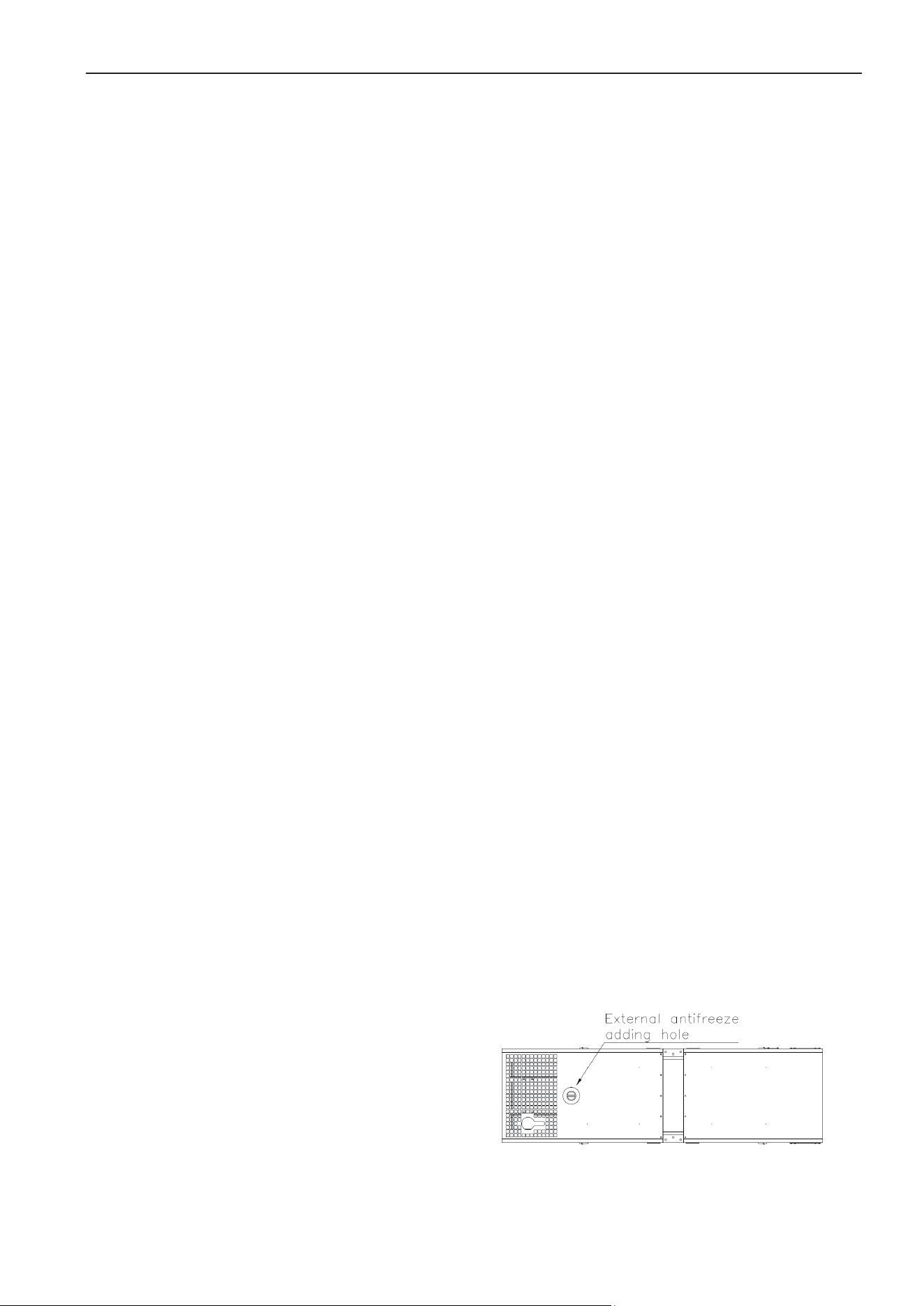
1.10.1Externalantifreezeaddinghole
Ourgeneratorsetshasbeenfacilitatedwithexternal
antifreeze filling hole. When user intends to add
antifreeze, He only needs to open the antifreeze
filling hole on the roof of canopy and the radiator’s
pressure valve cap to directly add antifreeze to the
hole,andeasilywatchtheantiǦfreezelevel.
1.10.2
Lubr
connectto
Our gene
r
lubricant d
i
outside. T
h
humanized
offers mo
r
When you
change it,
lubricantdi
s
1.10.3
Imp
r
Our canop
y
easy hoisti
n
generator
s
base frame
have desig
n
forklift op
e
serves the
power sup
p
frequently.
1.11
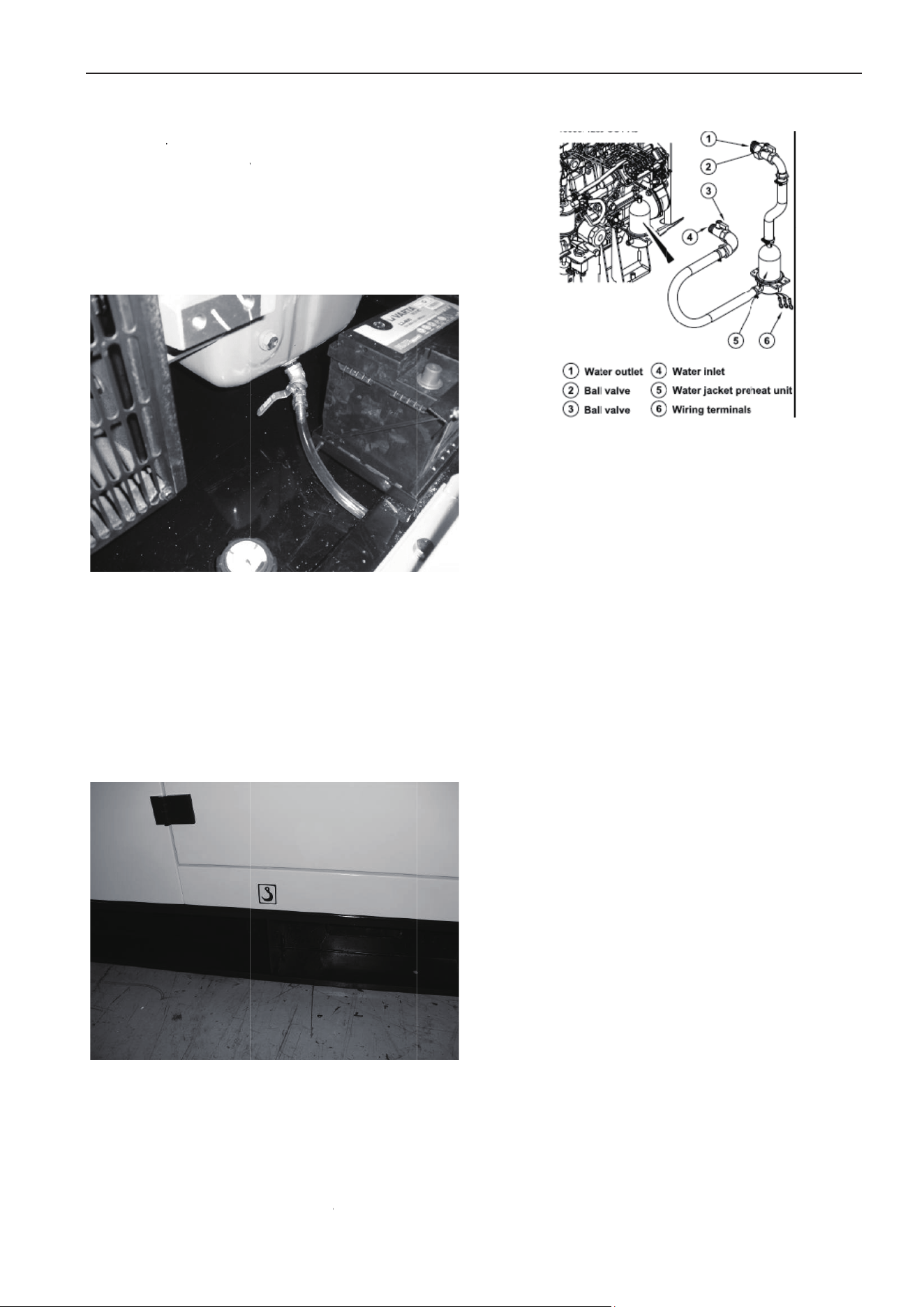
PreǦhe
a
Part)
Ourgenera
t
waterjack
e
toensuret
h
low tempe
icantdisch
a
outside
r
ator sets
i
scharge val
v
h
is lubrican
t
design fea
r
e convenie
n
want to d
i
you can ea
s
chargeball
r
oveddesig
n
y
generator
n
g and tra
n
s
et is facilit
a
. For thes
m
n
ed hoistin
g
e
ning in th
e
needs of cu
p
lier but ne
e
a
ter for ge
n
t
orsethas
b
e
t.Thepurp
o
h
atthegen
e
rature and
a
rgeholew
h
have been
v
e which c
o
t
discharge
ture of HY
U
n
t operatio
i
scharge su
r
sily make i
t
valve.
n
foreasyt
r
sets have
b
n
sportation.
a
ted with li
f
m
all power g
g
lug on the
e
base fra
m
stomers wh
e
d to move
n
erator set
b
eenfacilitat
e
o
setoinstal
e
ratorsetca
n
some emer
g
h
ichdirectl
y
facilitated
o
nnect dire
c
valve is a
n
U
NDAI Po
w
n for the
r
plus lubric
a
t
by openin
r
ansportati
o
b
een design
e
Standard c
a
f
ting hole
o
eneratorse
t
canopy ro
o
m
e, which
b
o have stat
i
the generat
o
(Optional
S
e
dwithhea
t
lthepreǦhe
a
n
bestarted
g
ency case
s
3
y
with
c
tly to
n
other
w
er. It
users.
a
nt or
g the
o
n
e
d for
a
nopy
o
n the
t
s, we
o
f and
b
etter
i
onary
o
r set
S
pare
t
erfor
a
teris
under
s
, and
a
l
d
a
1
.
E
x
g
e
b
a
c
o
v
i
s
u
c
a
a
n
c
u
p
c
o
l
so it can p
a
magedby
c
.
11
Others
x
ceptfora
b
e
nerator se
t
a
ttery for
o
rrugated
p
i
bration red
u
u
ch as base
a
nopy,thel
u
n
tiǦfreezea
n
u
stomer et
c
l
ease refer
o
ntract.
revent the
c
oldwinter
w
b
ovementio
n
t
has other
start moto
p
ipe, exha
u
u
ction unit,
a
frame typ
e
u
bricantuse
d
n
dotherpar
t
c
.For th
e
to gener
a
generator s
w
eather!
n
edcompo
n
main comp
o
r, battery
u
st elbow,
a
nd other a
l
e
fuel tank,
d
bytheeng
t
sspeciallyr
e
e
specific a
a
tor set p
a
User ma
n
ets from b
e
n
ents,the di
e
o
nents such
cable, silen
highǦeffici
e
l
ternativep
a
daily fuel t
a
ineatfirstti
e
questedby
ccessory p
a
a
cking list
n
ual
e
ing
e
sel
as:
cer,
e
ncy
a
rts,
a
nk,
me,
the
a
rts,
and

User manual
4
2 Installation
2.1
GeneralOutline
Correct installation of generator set is the
preconditionwhichensurethenormalworkingstatus
ofthegeneratorset.Theworkingroomforgenerator
set shall be designed specifically to meet the
expectedfunctionsandmaintenanceoperations,and
atthesametimethedesignofgeneratorsetworking
room shall conform to local government’s laws and
regulations on architecture, fire protection laws and
otherapplicableregulations.
2.2Transportation
During the period of shipment, protection shall be
made for the generator set. In addition, the
generator set shall be tightly secured in the loading
trucksothattoavoidany vibration duringshipment
which will cause the generator set’s components
loosen and even damaged. During the process of
shipment of generator set, no people or other
materialisallowedto place above
thegenerator set
sothatto avoid damage togeneratorset caused by
weight.
When loading or unloading the generator set to the
truck,forkliftorhoistingdeviceshallbeusedtoavoid
thegeneratorsetbecometiltedorfelltotheground,
whichcausesdamage.
Lifting holes have been designed on the common
base frame of our generator sets. Some of the
specifically designed generator sets has been
facilitated wi
th lifting holes on the roof and forklift
openingsonthebaseframeetc.Userscantransport
thegeneratorsetaccordingtotheguidancespecified
on the specif
ic labels sticked on the ge
ne
rator set.
Pleasedonotusetheliftinglugsontheengineoron
thealternatortohoistthewholegeneratorset.
2.3DesignforFoundation
Thefoundationwhichusedtoinstallandfixthediesel
generator set is very important, it must conform to
thefollowingrequirement:
ƹHaveenough hardnessand stability,sothattoavoid
deformation, which will affect the concentricity of
diesel engine and alternator and other accessory
parts.
ƹTosupporttheweightofthewholegener
atorsetand
toabsorbthedynamicimpactcausedbyunbalanced
forceandvibrationduringengine’srunningperiod.
ƹGeneratorset’s foundation is not allowedtoconnect
tootherarchitecture’sfoundation.
ƹ The width and depth of foundation shall meet
requirement.
ƹEnsurefoundation’slevelnessandsmoothness.
ƹIf possible, waste discharge sink canbe suedso that
the was
te oil can be discharged in a timely manner.
Cablechannelforgeneratorpoweroutputcableneed
tobereserved.
ƹNormally, concretefoundationisreliable,simple and
preferable. When pouring the concrete foundation,
please makesure the surfaceofconcrete is flat, and
no scrat
ch is allowed. Gradien
ter or similar
ins
truments need to be used during installation of
generatorsetanditsexhaustsystem.
The design of foundation can refer to following
calculationformula: (below is the diagram for diesel
generatorsetfoundation)
1.Generatordimensionlength×width:L1×W1
2.Foundationdimensionlength×width:L2×W2
L2=L1+400(mm)
W2=W1+400(mm)
3.B=2×M/(L2×W
2×D)
B:Thicknessoffoundation
M:Generatorsetweight
L2:Lengthoffoundation
W2:Widthoffoundation
D:DensityofConcrete(referto2322kg/m3)
(FoundationdrawingRefertoAPPENDIXA)
2.4DesignforGeneratorSetWorkingRoom
Theinstallationofgeneratorsetshallbedesigned,so
that to meet the demand of planned operation and
maintenance.Thecompleteinstallationshallconform
to local architecture laws, fire protection laws and
other applicable regulations. Except the above
matters, there are other matters needs your
attentionasfollows:
ƹEnsuredieselenginegeneratorsetworkingroomis
furnishedwithrainproof,su
nscreen,andwindproof.
ƹEnsuredieselenginegeneratorsetworkingroomhas
good ventilation and good exhaust system, and the
areaforventilationissufficient,andatthesametime
use pipes to let out the hot air generated from the
radiatorandpreventthehotairfromreturning.
ƹE
nsurethewastegasgeneratedduringgeneratorset
running period can be discharged to outside timely,
andtryyourbesttoreducetheadverseeffectcaused
to environment. The silencer and exhaust pipe shall
be supported by the roof, the supporter shall allow
the exhaust pipe to ex
pand. It is not permitted to
install the exhaust system directly on the generator
set.
ƹ Enough space shall be reserved for the diesel
generator set for convenience of cooling, operation
andmaintenanceetc.Generallyspeaking,noforeign
material is allowed to be placed within the area of
User manual
5
1~1.5 m of distance from the generator set and
1.5~2mabovethegeneratorset.
ƹThe generator set working room shall be furnished
with fire extinguish hydrant which conform to the
specifiedstandard.
ƹEmergency lighting facilities shall be installed in the
generator set working room for the convenience of
operationandmaintenance.
ƹ
No combustible and explosive materials are allowed
tobeplacedinthegeneratorsetworkingroom.
Belowisthelayoutfortheopensystemgeneratorset
workingroom.
(FoundationdrawingRefertoAPPENDIXB)
Note:
Our company can make drawings and design
installation dimensions for generator set working
roomaccordingtocustomer’sspecialrequirements.
Belowisthelayoutforthecanopysystemgenerator
setworkingroom.
(FoundationdrawingRefertoAPPENDIXC)
Note:
Canopied generator set can work outdoor directly. If
users wants to operate the generator set indoor,
above diagram can be taken as reference. we can
designthelayout of generatorset working room and
installationdimensionaccordingtocustomer’sspecial
requirements.
2.5InstallationofGeneratorSet
2.5.1
Locatethepositionofgeneratorset
Vibration reduction units have been installed on our
generator sets (except a few generator sets don’t
havethiskindoffacility).Userscantakereferenceon
the installation diagram, correctly install the
generatorsetonaflat andhardfoundation,usethe
expansionboltstotightlyfixthegeneratorsettothe
concretefoundationthroughtheinstallationholeson
the base frame. When no special requirement is
needed,
we don’t suggest customers to install
additionalvibrationreductionunits.
Softconnectionisneededtoconnectthepartsofthe
generator set to outside. For example: corrugated
vibration reduction pipe has been used to connect
exhaust pipes, air exhaust path, fuel inlet pipe, fuel
return pipe and busbar cable etc.,
all of these parts
needtousesoftconnections.Onlyinthiswaywecan
reducetheadverseeffectcausedbythevibrationof
generatorsettotheminimumextent.
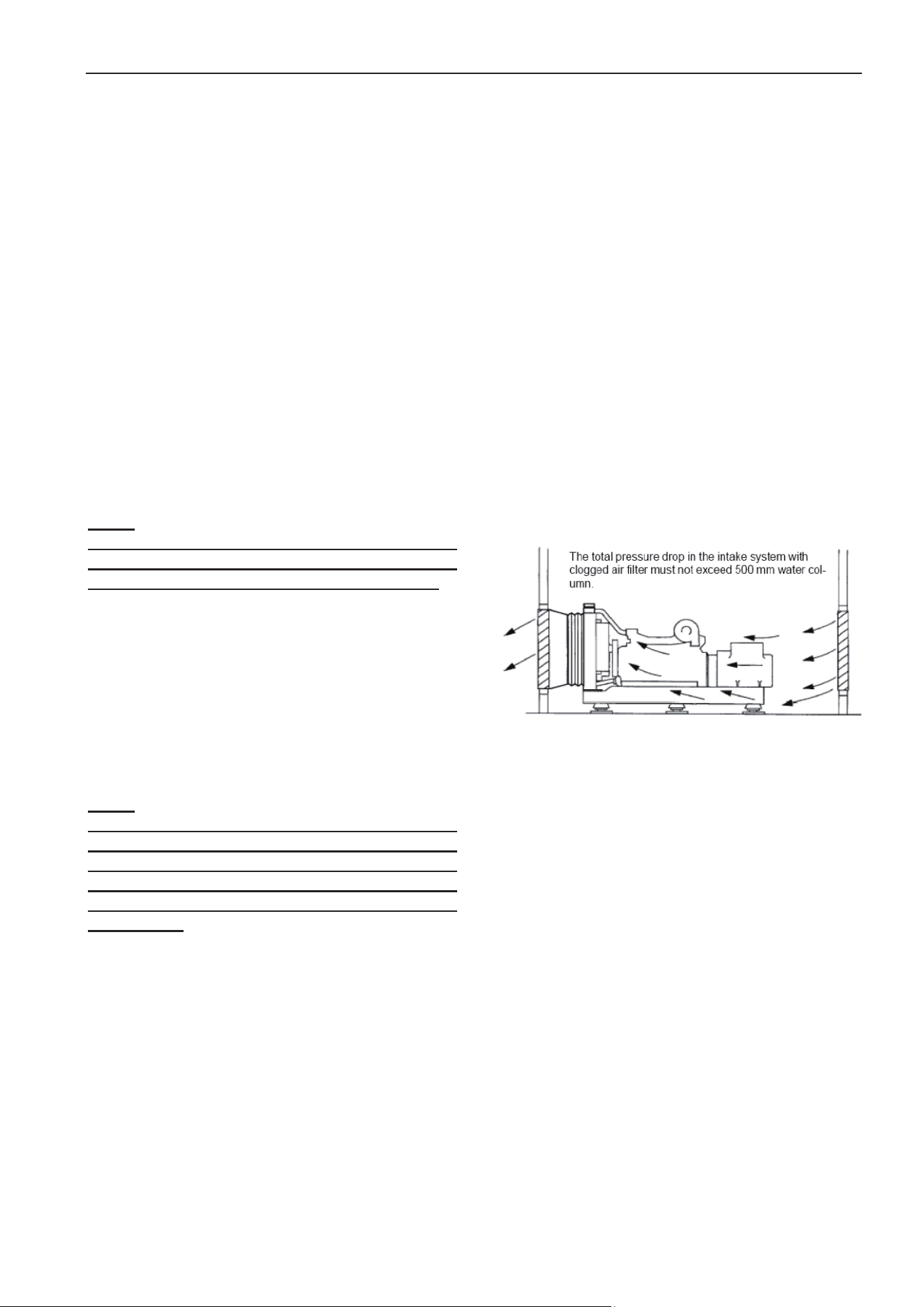
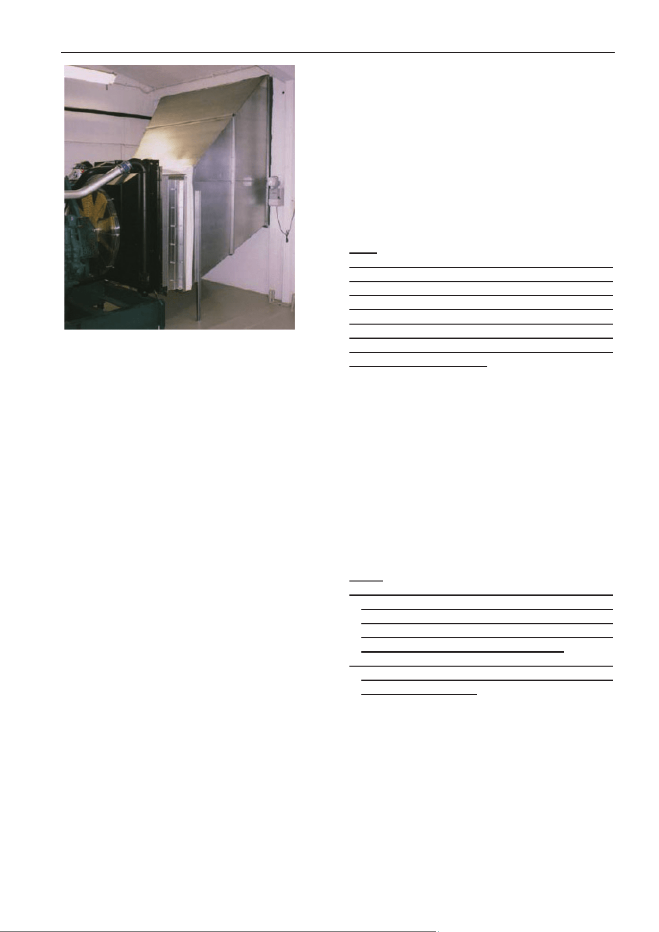
2.5.2Ventilation
Whenageneratorsetwithacompletesetofradiator
assemblyhasbeeninstalledintheworkingroom,the
basic principle is to discharge the hot air in the
working room to outside and let in the low
temperature air from outside, and try you best to
avoidthehotaircomeinfromoutside.
Thediagramintherightsidedemonstratestheideal
positionofageneratorsetintheworkingroom.
The purpose of this arrangement is to get cold air
fromthelowestpointasmuchaspossible,andforce
themto
passthroughtheradiatorcore,andthenlead
themout.
Userscanusemetalplate or canvastomakeawind
guide cover, the connection between wind guide
cover and th
e radiator shall be soft connection, so
thattocutoffthetransmissionofvibrationfromthe
generatorset,andalsoensurethehotairexhaustto
outsidethoroughly.
The effective circulation sectional area inside of the
wind guide
cover shall be bigger than 1.25 times of
thefrontfaceareaoftheradiatorcore.Andthewind
guide cover shall be smooth, no sharp angle and
cambersothattoreducetheresistancetothewind.
At the same time, the effective circulation sectional
areaintheairinletopeningshallalsobebiggerthan
1.25times
ofthefrontfaceareaoftheradiatorcore.
Whentheusershaveinstalledmeshcoverorshutters
in the air inlet /outlet opening or there is too many
cambersin th
eair inlet/outlet opening, theeffective
air circulation sectional area
will be reduced and
resistancewillincrease,andtherefore, it’s necessary
tofurtherincreaseaircirculationarea.
User manual
6
Under normal conditions, the air volume generated
from the radiator’s fan is enough to meet the
requirementoftheworkingroomventilation.
Theairinlettemperatureoftheengineshallbebelow
30 degree Celsius. If the air inlet temperature keep
rising above 30 degree Celsius, the engine’s output
power will be reduced, an
d therefore fresh air from
outside shall be introduced into the generator set’s
workingroominatimelymanner.
If the generator set is furnished with a remote
radiator, forced air circulation for the generator set
working room is a
must. The forced air circulation
need two fans, one fan is responsible for air intake,
another is air exhaust, which exhausts hot air to
outside.
Whentheengineisfurnishedwithpropelledfan,itis
recommended that a separate pipe is needed to
exhaustthegaswhichgeneratedfromthecrankcase
to
outside. Otherwise the exhaust gas from the
crankcasewillaccumulateontheradiator,whichwill
cause the radiator stuck by dirty material, and as a
result,theheatǦsinkingcapacitywill
bereduced.
2.5.3Exhaust
Our standard configuration diesel generator sets
provide accessories such as industry heavy silencer,
softcorrugatedpipeandelbowetc.Userscandesign
the exhaust system of generator set working room
by themselves. When design and install the exhaust
system,pleaseconsiderthefollowingaspects:
ƹEnsurethetotalexhaustbackpressurenohigherthan
the maximum allowed value specified by the
engine(usually generator set’
s maximum exhaust
backpressure is no more than 5Kpa) Fix the exhaust
system to make sure the exhaust manifold and
turboͲchargerarenotsubjecttotheverticalpressure
andsidestress.
ƹ Reserve some space for hot shrinkage and cold
expansion.
ƹRes
ervespaceforgeneratorsetvibration.
ƹReduceexhaustnoiselevel.
Overload of exhaust backpressure will cause
followingadverseeffect:
ƹOutputpowerloss
ƹFuelefficiencyreduce
ƹExhaustgastemperaturerise
Note:
When more than one generator set are installed, try
not to discharge all of the generator sets’ gas from
one exhaust path. If no separated exhaust pipe is
allowed, under the condition that the total
backpressurewillnotexceedthegeneratorsets’total
backpressure a moveable separate panel shall be
installed inside of the branch exhaust pipe so that to
preventthegasfromreturn.
In the exhaustsystem, softcorrugated pipeshall be
used to connect the exhaust pipe with the
turbocharger, this pipe has three functions as
follows:
ƹSeparate the diesel engine with vibration and the
weightofexhaustpipe.
ƹCompensatetheheatexpansionofexhaustpipe.
If the diesel generator set is inst
alled on the
antiǦvibration base frame, the corrugated pipe can
compensatesidewaymovement
whenenginestartor
stop.
Note:
1. Serious damage will occur when rain or condensed
water enter into engine’s exhaust system.
Therefore, one water discharge opening shall be
installed in the long exhaust pipe, the position of
whichshallbeclosetothegeneratorset.
2. When the top of the exhaust pipe is above the
architecture, lightening protection is needed
(connecttotheground)
2.5.4Noisereduction
Whendieselgeneratorsetisrunning,normallyitwill
generatenoiselevelof90110dB,andthemorethe
load,thehigherthenoiselevel.
Inordertomeetthenoiselevelstandardsestablished
bythelocalen vironmentalprotectionbureauandto
prevent the noise pollution caused to ambient
environment, which will affect people’s normal life,
to reduce no
ise level of diesel generator set is also

User manual
7
veryimportant.
Noisereduction engineering is a comprehensive and
professional engineering. During the process when
users try to design the scheme for noise reduction
project, at the same time please fully consider the
bottom limit of air inlet/outlet volume needed by
engine’s normal running and the maximum allowed
value for exhaust backpressure etc. Otherwise, the
noisereductionprojectwil
lseriouslyaffectgenerator
set’s output power, and make generator set’ s
temperature rise, cause frequent malfunction of the
generator set, and even it will sho rten the life
expectancyofgeneratorset.
Note:
HYUNDAI Power can provide customers with overall
soundproofgeneratorset.
2.6Coolingsystem
Ourstandardconfigurationdieselgeneratorsetsare
closed cycling water chilling units with fan and
radiator installed. Closed water chilling engine drive
the cooling pump to generate circulation power,
which keep the antiǦfreeze in the paths of cylinder
body and cover continuous circulation and heat
elimination.Engine’scoolingpump,radiator(orheat
exchanger) forms a closed, pressure cycling and
coolingsystem.
The most common cooling system is cooling fan
directly drivenby radiator and engine, which can be
replaced by heat exchanger, remote
radiator or
remotecoolingtower etc.Iftheinstallationposition
of the remote cooling fan is relatively higher,
transmission radiator is needed to prevent the
damageofheatexchangercausedbytoobiginternal
pressure.
Note:
The dirty material stay in the radiator’s core will
greatly affect radiator’s cooling capacity. And
thereforeitisnecessarytocleantheradiatoroften.
2.6.1
Coolant
Cooling system shall use the coolant which can
protecttheenginefromcontaminationandfreezing.
Coolant shall be a mixture of pure water and
antiǦfreeze or pure water and antiǦrust fluid. In this
mixture, water PH value shall be between 68,
usually suggest to use distilled water.The specific
mixingratioshallbeaccordingtolocalweather,and
that of the coolant recommended by the engine
supplier,andreferencetotheoperation(preparation)
manual of the coolant. Mix the liquids in a separate
container ev
enly and then add the mixture into the
radiator,ensuretheantiǦfreezewillnotfreezeunder
low temperature. In the area wh
en there is low
possibilityoffreezing,thecoolantcanbeamixtureof
waterandantiǦrust, according to the antiǦrust which
recommendedbytheenginesupplierandrefer toits
operation manual, mix the liquids in a separate
container evenly and then add the mixture into th
e
radiator.AtthefirsttimewhenantiǦrustisadded,the
generatorsetshallbekeptrunninguntilitgettohot
sothattoachievethebesteffectofantiǦcorrosion.
Engine’s coolant shall have three functions listed as
below:
ƹProvideenoughheattransmissioncapacity
ƹ Preven
t all meta
l material and sealing material
within the cooling system from corrosion(Cave
corrosion)
ƹProvidesufficientantiͲfreezecapacity
Warning:
!TochoosetheantiǦfreezewhichisrecommendedand
approved by the qualified engine supplier is the
criticalpointtoensureengine’snormalrunning.
!DonotmixtheantiǦfreezeandantiǦrustofanytypes,
this will generate a large amount of bubble and
reducethecoolant’sperformance.
! If the antiǦfreeze used in the generator set is of bad
quality and not approved by the engine supplier,
which cause the malfunction of the generator set
(water leakage, contamination and etc.), this
malfunction(s) does not belong to the scope of
warranty.
2.6.2Changeofcoolant
TheeffectofantiǦfreezeandantiǦrustwilldecreaseby
thetimeperiodofservice.Andthereforeperiodically
change of antiǦfreeze is a must. The mixture of
antiǦfreeze shall be changedin every two years. The
mixtureofantiǦrustshallbechangedatleastonetime
everyyear.Andif filter of thecoolantisinstalled,at
leastthisfiltershallbecha
ngedineveryhalfofyear
(pleaserefertotheengineoperationmanualforthe
specificintervalsofthechangesrequired).
When it is time to discharge the coolant, makesure
thegeneratorsethasbeenshutdownandtheengine
hasbeenfullycooleddown,thenopentheradiator’s
liquid adding hole. After that open the discharge
valve installed in the radiator and in the engine
respectivelytodischargethewater. Ifthegenerator
set is furnished with coolant filter, it shall be
detachedfromtheengineandbechanged.
2.6.3Cleaningofcoolingsystem

User manual
8
Whenchangethecoolant,cleaningisneededforthe
cooling system, the cleaning procedures are
suggestedasfollows:
ƹEmptythecoolingsystem
ƹUsewatertorinsecoolingsystem
ƹFeed 15%~20% condensed coolant to the cooling
system, timely run the generator set for one or two
timesthendischargethecoolant
ƹEm
pty the cooling sy
stem then use normal mixed
liquidtorinse
ƹIf contaminant still exists, then repeat the cleaning
procedureuntilnocontaminantexistsinthesystem
ƹAfter the system has been fully rinsed, feed new
coolantwhichhas beenmixed accordingto specified
proportion
Note:
Ifthecoolingsystemiscleanedperiodically,onlyrinse
it with small amount of additives or clean water is
enough.
2.6.4Feedingofcoolant
ƹBefore adding coolant to the coolant system, please
make sure the radiator ‘s discharge valve and the
engine’sdischargevalvearetightlyclosed.
ƹAdd the coolant to the system in a proper speed so
thattoavoidaircockbeingformedinthesystem.
ƹAir shall be discharged through the a
dding hole or
thedischargevalveintheenginebody.Ifthecooling
sy
stemis furnished with heater,thecontrolvalvefor
theheatershall be opened.Ensureventilation ofthe
unitwhenaddingthecoolant.
Note:
The air discharge valve in the engine body shall be
locatedinthetoppointofthewaterpathornearthe
thermostat or water temperature sensor, or you can
slightly loose the water temperature sensor and
reǦtighten it when you see coolant run out from it so
thattodischargetheair.
ƹWhen adding the coolant, the surface of liquid shall
reach to the level that is 5 centimeters below the
radiator’s welded surface (or shall reach the level
indicating Line). Be sure that the generator set has
stopped and become fully cooled before adding
Coolant. Before the system is capable of ven
tilation
and the liquid is added to the r
equired level, please
don’tstartthegeneratorset. Afterthecoolantbeing
fed,pleasestartandpreͲheatthegeneratorset,and
at the same time check the liquid level and add
coolant if needed. The coolant which needs to be
added to the radiator
shall be of the same
specificationasthatexistingintheradiator.
ƹFor some generator sets installed with coolant filter,
pleaseopenthefilter’svalvebeforeputintouse.
2.7Lubricantsystem
Lubricant system is composed of oil pan, oil pump,
strainer, oil pipe, oil cooling unit, oil filter unit, and
the oil path inside of the engine and all kinds of
lubricantpartswhichareinrelativemotionetc.The
main purpose of the lubricant system is to provide
sustainedtemperedoilfilmbetweenthepartswhich
areinmotionsothattoreducefrictionandwear,
and
draws off part of the heat absorbed by the parts,
bath mechanical part, improve sealing effect and
preventrustfromeachpart’ssurface.
Userscandeterminethemodeloflubricantaccording
to the specific working environment and conditions.
For the first time lubricant, normally users shall
change it within 100 hours upon and from the time
when
thegeneratorsetfirststarted.(details refer to
enginemaintenancemanual)
Note:
Thecriticalpointistousequalifiedlubricantoilwhich
is with proper viscosity and conform to the engine’s
requirement,andperiodicallychangethelubricantoil
and oil filter so that to ensure the generator set’s
normal working. The malfunctions caused by wrong
modeloflubricantoilwithlowquality orlongtimeno
change of lubricant oil, or oil filter do not belong to
thescopeofwarranty.
We recommend that high quality multi grade SAE
15W/40 high service engine oil in diesel engines are
used. At ambient temperatures aboveǦ15 degree
Celsius is 15W40. The minimum API oil quality levels
recommendedforuseisCH / CIǦ4, CH or CIǦ4 canbe
used in areas where CF4 oil is not yet available, but
the oil interval must be reduced API CA, CB, CC, CD,
CE,CG4categoriesnotrecommended,donotuse.
2.8Fuelsystem
Ourgenerator sets requires thefuelǦdieselshall be
clean, without air and water and with proper
pressure, of which all kinds of parameters such as
sulphur content etc. shall meet national standards,
and end use temperature grade meet the
requirement of customer’s working environment.
Generally generator set’s fuel system includes two
parts, that is,engine’s fuel system and external fuel
system. HYUNDAI is only responsible for installation
of the external fuel system which includes fuel tank
andconnectingfuel
pipesetc.
2.8.1FuelRecommendations

User manual
9
The following fuel oil specification is typical. For a
specific engine refer to manufacturers’ data sheets
forfueloildetails.
FuelRecommendedPhysicalPropertiesFeature
Viscosity
1.3to5.8centistrokes(1.3to5.8mmpersecond)at40°C(104°F)
(ASTMD445)
CetaneNumber
40 Minimum above 0°C (32°F) ~45 Minimum below 0°C (32°F)
(ASTMD613)
SulphurContent
Nottoexceed0.5massper cent*(ASTMD129or1552)
ActiveSulfurCopperStripCorrosion
NottoexceedNo.2ratingafterthreehoursat50°C(122°F)
(ASTMD130)
WaterandSediment
Nottoexceed.05volumepercent(ASTMD1796)
CarbonResidue
Not to exceed 0.35 mass percent on 10 volume percent
residuum(ASTMD524orD189)
Density
42to30°APIgravityat60°F(0.816to0.876g/ccat15°C).
(ASTMD287)
CloudPoint
6°C (10°F) below lowest ambient temperature at which the fuel
isexpectedtooperate(ASTMD97)
Ash
Not to exceed 0.02 mass percent (0.05 mass percent with
lubricatingoilblending)(ASTMD482)
Distillation
The distillation curve must be smooth and continuous (ASTM
D86)
AcidNumber
Nottoexceed0.1MgKOHper100ML(ASTMD664)
Lubricity
3100 grams or greater scuffing BOCLE test or Wear Scar
Diameter(WSD)lessthan.45mmat60°C(WSDlessthan.38mm
at25°C)asmeasuredwiththeHFRRmethod.
DieselFuelPropertyDefinition
AshǦMineralresidue in fuel. Highash content leads
to excessive oxide build up in the cylinder and/ or
injector.
Cetane NumberǦIgnitability of fuel. The lower the
cetan number, the harder it is to start and run the
engine.Lowcetanefuelsignitelaterandburnslower.
This could lead to explosive detonation by having
excessivefuelinthechamberatthetimeofignition.
Incoldweatherorwithprolongedlowloads,
ahigher
cetanenumberisdesirable.
SulphurǦAmountofsulphurresidueinthefuel.The
sulphur combines with the moisture formed during
combustiontoformsulphuricacid.
ViscosityǦ Influences the size of the atomized
dropletsduringinjection.Im
properviscositywilllead
todetonation,powerlossandexcessivesmoke.Fuels
that meet the requirements of ASTM or 2.0 diesel
fuelsaresatisfactorywithfuelsystems.
2.8.2
Fueltank
Ourgeneratorsetsprovidebaseframestylefueltank
for customer. The base frame style fuel tank is
installed with fuel tank, fuel pipes and fuel level
indicator. This fuel supply system does not need
customertomakeotherinstallations.Customersonly
needtoaddfueltothebaseframe.
Users who intend to self manufacture the fuel tank
shall use stainless steel or steel plate
to make the
backup tank, do not make painting or galvanization
inside of the fuel tank so that to avoid the possible
chemical reaction between these kind of materials
anddiesel,whichmaygeneratethematerialharmful
tothe generatorset and decrease the quality, Merit
Rating and combustion efficiency of diesel. In
addition,theconfigurationoffueltankassemblyshall
beas
follows:
ƹAirventilationpipeabovefueltanksurface
ƹManholeonthetopsurfaceoffueltank
ƹWatchwindowforfuellevel
ƹDischargeva
lveatthebottomoffueltank
ƹ
Groundcablebetweenfueladdingholeandfueltank
ƹSeparate panel with holes between fuel supply area
andfuelreturnarea,sothattoreduceheatexchange
ƹTheendoffuelsupplypipeshallbe50mmabovethe
bottom of base frame so that to avoid the deposit
and wat
er at the bottom of fuel tank being sucked
intofuelsupplypipe.
ƹPart of the generator sets’ fuel level shall be higher
thanthepositionoffuelinjector,sothattoavoidfuel
returnfromfuelinjector,whichcausestartdifficulty.
2.7.2Installationoffueltank
ƹ The position of the fuel tank shall ensure the
maximumsuction fuelheadisno lessthan2meters.
Suction fuel head of the fuel transfer pump shall be
calculatedfromthebottomofthefueltank.
ƹThe position of the fuel tank shall ensure maximum
returnfuel head no lessthan 1.5 mete
rs.Returnfuel
head shall be calculated from the top of the base
frame.
ƹThearrangementofthefuelpipeshallavoidthefuel
being affected from the heat elimination from
generatorsettoomuch.
ƹThe maximum temperature of the fuel before fuel
pumpshallbelowerthan60degreeCelsius.
ƹNol
eakage offuelandai
risallowedinthefuelinlet
andfuelreturnpipe.Thisisveryimportant.
ƹHose need to be used to connect generatorset with
fuel transfer pipe. If the generator set use soft
connection (through vibration reduction unit), hose
shallbeused.
ƹWhen engi
ne’s fuel inle
t pipe is above 6 meters and
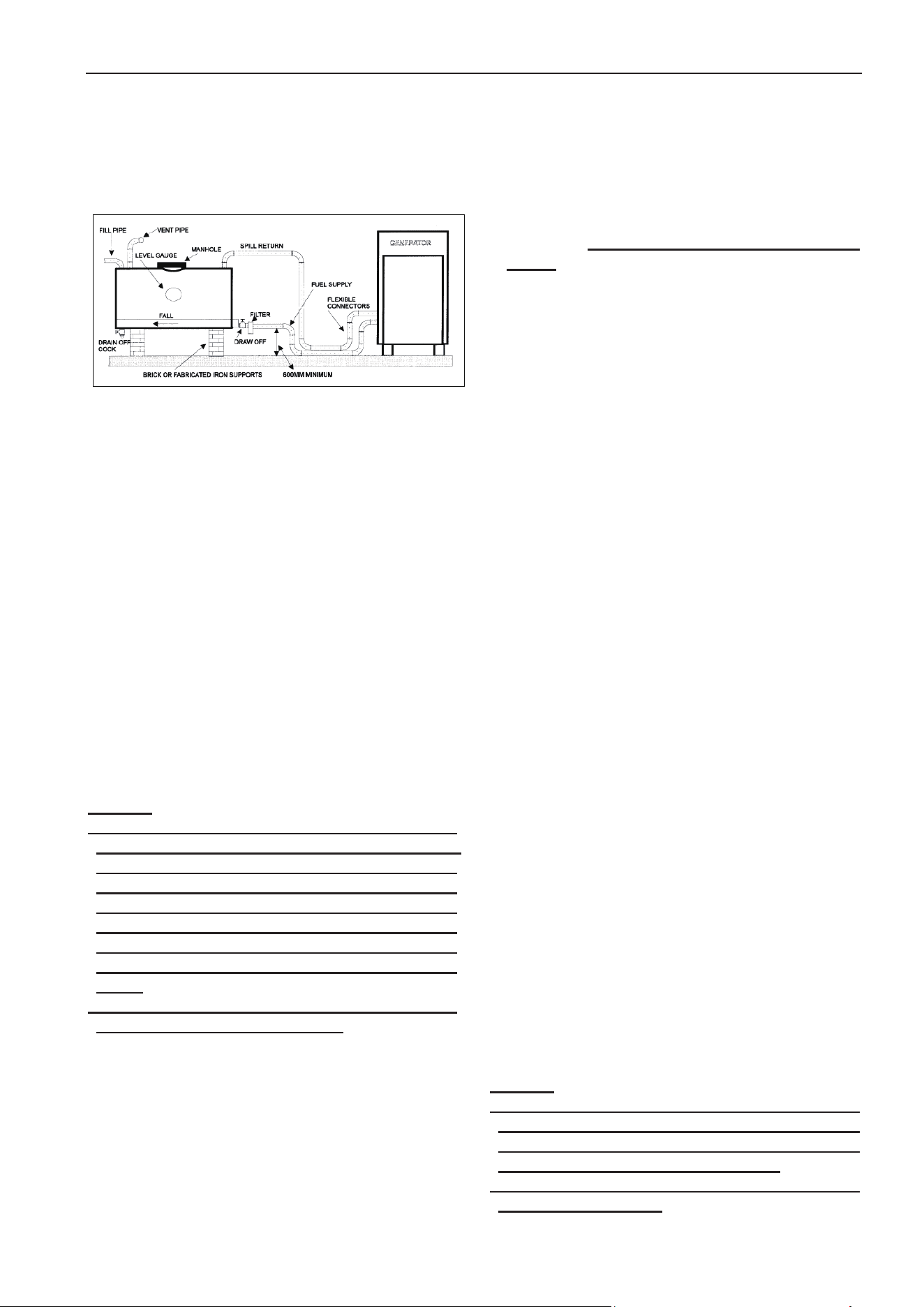
User manual
10
below10meters,thisfuelinletpipe’sinsidediameter
shall be at least 20% bigger than that of the hose
installed in this engine. Fuel return pipe shall be
connected to the top of fuel tank. Don’t directly
connectittofuelinletpipe.
2.7.3Fuelconsumption
Thecontentofdieselplaysaverycriticalroleindiesel
engine’s performance, life expectancy and the
content of discharged material. In order to achieve
the rated power, fuel economy and specified
emission standard, only the fuel which refer to
international standard or national standard can be
used.
The parameters of diesel fuel include low
temperaturefeature,sulphurcont
ent,specificgravit
y,
water content and foreign
material content shall be
thefirstprioritywhenuserneedtochoosethequality
ofthefuel.Differentqualityoffuelwilldirectlyaffect
dieselgeneratorset’sstart,lubricating,outputpower,
discharge,andfuelfilterchangecycleetc.
Specific requirement for fuel please refer to engine
operationmanualwhichattachedwiththegenerator
set.
Wa
rning:
! When you intend to add fuel into the fuel tank,
pleasemakesurethegeneratorsethasbeenstopped.
Only after the added fuel become static for some
time, this generator set can be started again. This
way to avoid the foreign material in the diesel fuel
being sucked to fuel supply hose, which will cause
fuel filter stuck and fail to supply engine with
sufficient fuel, and in turn decrease the output
power.
! The malfunction caused by bad quality of fuel does
notbelongtothescopeofwarranty.
2.8Controlsystem
Our diesel generator sets has been furnished with
control panel. All of the control panels choose
importeddigitalmeterasthecoreofcontrolsystem
forthegeneratorsets.
ƹ Digital control panel: the generator set can be
controlledlocallybymanual,andalsocanbestarted
or stopped by remotecontrol(controlled by ext
ernal
signalline)usersarerequiredtocorrectlyconnectthe
signal line to this control panel.(details see the
controlpaneloperationmanual)
ƹAutomatictransferpanel(optional):istheautomatic
transfer switch for transfer between generator set
and mains.(details refer to control panel operation
manual
)
2.9Battery
Our generator set standard configuration provides
start battery as accessory parts. According to user’s
different requirements, our company can provide
twotypesofbatteries,thatishighefficientplumbous
acidbatteryandmaintenancefreebattery.
If maintenance free battery is used, users only need
toconnectcablesforthebattery.
If plumbous acid battery is used, beforebeing used,
users need to use standard battery to electrolyze
primary liquid. Untighten the battery cover, slowly
pourelectrolyteintothebatteryuntiltheelec
trolyte
level reach the indicating line in the internal polar
plates(notallowtoexceedthisline),thentakeoffthe
lablefrom the battery cover’s air holeand close the
cover.Aftertheelectrolytebeingadded,pleasedon’t
use it immediately, keep the battery in static status
for thirty to sixty minutes. In low temperature
environment, this time period need to
be extended
(use battery charger to charge battery when
necessary)
Users can use the standard connecting cable
attached with the generator set, the red color shall
be connected to
positive polar, black (or blue) to
negative polar, correctly connect to the generator
set’sstartmotor.Mostofthedieselgeneratorsets’
cables have been connected to the engines before
shipment.
Theenergy storage capacityof the start battery will
determine if the diesel engine generator set can
smoothly start in a specified period. During the
process of generator sets running, the charging
alternator installed in the engine will continuously
chargebatteryto
startbattery.
Warning:
! Please ensure the connection for positive and
negative polar is correct. Wrong connection will
cause malfunction! (Wrong connection will surely
causedamagetothechargingalternator)
!Whengeneratorsetisrunning,batterycablesarenot
allowedtobecutdown!

User manual
11
2.10ElectricalConnection
Only full qualified and experienced electrical
technicians should carry out electrical installation,
serviceandrepairwork.
Warning:
! Make electrical connections in compliance with
relevant electrical codes, standards or other
requirements.
2.10.1Cabling
Due to movement of generating sets on their
vibrationmounts,theelectricalconnectiontotheset
should be made with flexible cable. The cable must
be suitable fortheoutput voltage ofthe generating
set and the rated current of the set. In determining
the size, allowances should be made for ambient
temperature. Method of installation, proximity of
othercables,etc.Allconnectionsshouldbecarefully
checkedfor
integrity.
Currentcarryingcapacityofpowercablesthatwillbe
given in APPENDIX A. On the other hand, there is a
onemoreimportantpointwhilecablecrosssections
arebeingselected.Ifthedistancebetweenloadand
generator is too length, voltage falling at the load
side can be too much at the transient current
duration. The voltage drop across a cable can be
determined
asfollows:
1000
)XsinRcosIL3
ȴU
MM
uuu
ȴUVoltagedrop(V)
LLengthofconductors(m)
IRatedcurrent(A)
RResistance(ɏ/kmtoVDE0102)
XReactance (ɏ/kmtoVDE0102)
RefertoAPPENDIXECableCurrentloadstandard.
2.10.2Grounding/EarthingRequirements
The frame of the generating set must be connected
to an earth ground. Since the set is mounted on
vibration isolators, the ground connection must be
flexible to avoid possible breakage dueto vibration.
Ground connection cables or straps should have at
least full load current carrying capacity and meet
applicableregulations.
2.10.3InsulationTest
Before starting the generating set after installation,
test the insulation resistance of the windings. The
Automatic Voltage Regulator (AVR) should be
disconnectedand the rotating diodes eithershorted
out with temporary links or disconnected. Any
controlwiringmustalsobedisconnected.
A500VMeggerorsimilarinstrumentshouldbeused.
Disconnect any earthin
g conductor connected
between neutral and earth and megg
er an output
terminaltoearth.
Theinsulationresistanceshouldbeinexcessof1Mȳ
toearth.Shouldtheinsulationresistancebelessthan
1Mȳwindingmustbedriedout.
2.11Powerdistributionsystem
Ourdieselenginegeneratorsetusethreephasefive
line system for power distribution. That is, three
phase live wires, one neutral line, one ground line.
The neutral line and the ground line are not
connected. Users can choose three phase four lines
forpowerdistributionaccordingtorequirementthat
is to connect the neutral line to the ground (base
frame),sothattosolvetheproblemoffeintthatthe
neutralline
sometimesiselectriferous.
Note:
HYUNDAI Power series diesel engine generator sets
require users to safely connect generator sets and
baseframestotheground,pleaserefertotheground
labelforconnectingpoint.

User manual
12
3Operation
3.1
InspectBeforeOperation
After finished installation, our diesel engine
generator set can be putinto use. Each time before
starting the generator set, following items shall be
checkedwithoutfail:
ƹIf there is foreign material exists in the surface of
generator set or in the ambient environment which
mayhamperthegeneratorset’soperation.
ƹIf the air inlet and ven
tilation path in the generator
setworkingroomisexpedite.
ƹIftheantiͲfreezelevelisnormal.
ƹIftheairfilterindicatorworkswell
ƹIfthelubricantleveliswithinthespecifiedrange
ƹIfthefuelvalveisopen,ifthefuelhasbeensupplied
totheenginenormally.
ƹIf the cable has been connect
ed to the battery in a
correctway.
ƹCheckiftheloadequipmenthasbeenwellprepared.
Whenthegeneratorsetdirectlyconnectstotheload,
theairswitchshallbecutoffbeforestart.
Warning:
Operators shall establish good operation
(maintenance) procedure, this is the precondition for
generatorset’ssmoothrunninginlongtimeperiod.
3.2Generatorset’srunning
3.2.1
PreǦheat
For the generator set which is installed with
preǦheater,operatorsneedtodecideifpreǦheatingis
needed before start the generator set according to
environmenttemperature.Thecontrolpanelwhichis
installedwithpreǦheatswitchcaninstructtheengine
tostart thepreǦheatersothattoachievethepurpose
ofpreǦheating.
3.2.2Connecttopower
Turntheairswitchinthecontrolpanelfrom“OFF”to
“ON”, watch the panel until the background light
turn on, that means the control panel has been
successfully connected to the power. At the same
time make sure the fuel pipes are open, and the
speed governor or the control unit in the electronic
fuelinjectiongeneratorsetisunderworkingstatus.
3.2.3Start
Part of the generator set control panel has been
furnishedwithidlespeed/fullspeedtransferswitch,
userscan choose iftheengineneedtobestartedin
idlespeedorinonetimefullspeed.Usuallythetime
period for idle speed shall not exceed five minutes.
Do not run the generator set in idle speed in a long
timeperiod.
Press on th
e start button, the duration shall not
exceed30seconds,enginewillbestartedbythestart
motor.Assoonastheenginebestartedsuccessfully,
you can release the start button and the generator
setwillenterintorunningstatus.
Suggestion:
Inordertoextendthelifeexpectancyofstartbattery
and start motor, the duration forone time start shall
becontrolled within5to10seconds.Ifonetime start
fails, stop for some time and begin the second time
startprocedure.
For the control panels which are installed with
selfǦstart(or communication) instrument, the
generator set preǦheating, startǦup period and
starting times have been controlled by the program
(this program can be set and modified by user).
Operation procedure please refers to operation
manual.
When the generator set control panel has
malfunction(s), timely overhauling is needed before
ReǦstart
thecontrolpanel.
Warning:
Forany startup which is made through force, not by
control panel, the malfunction caused by it do not
belongtothescopeofwarranty.
3.2.4Running
When the generator set begins full speed running,
andthealternator’svoltageandfrequencybecomes
normal and stable, operators can put the generator
setintonormalrunning.
Duringthegeneratorset’srunningperiod,operators
shalloftenwatchandchecktheparameterssuchasif
the generator set is running normally, if the control
panelinstrumentisindicatingtherightpo
sition,ifthe
controlpanelhaspreǦwarningindication,andthefuel
levelinthebaseframeetc,andmakerecordforthe
parameters.(seeattachfile)
3.2.5Emergencystop
In case the generator set was found to have severe

User manual
13
malfunction or power distribution malfunction.
Please press down the emergency stop on the
controlpanel, sothattoimmediatelyshutdownthe
generatorset.Undernormalcondition,pleasedonot
useemergencystoptostopthegeneratorset.
3.2.6Normalstopthegeneratorset
Before stop the generator set under normal
condition,firstseparatetheloadfromthisgenerator
set, then run the generator set with no load for a
certain period of time(3 to 5 minutes), so that to
make sure the generator set become fully cooled,
afterthatthegenerator setcan be stopped. (Please
donotmakecoolingrunningunderidlespeed)
For some generator sets which have been
installed
with stop solenoid, it is impossible to stop the
generator set by cutting off the key switch on the
controlpanel.Correctoperationis:topressthestop
button when the power of the control panel being
resumed,onl
yinthiswayyoucanstopthegenerator
set.(press the stop button until the generator set
fullystoprunning)
3.3AfterRunning
After the generator set stop running, it is necessary
tocarryonfollowingjobs:
ƹTo check if the generator set has “three leakage”
(lubricant,fuel,antiͲfreezeleakage)
ƹShutdownfuelvalve
ƹShut down air inlet and air exhaust facility in the
generatorset’sworkingroom(whennecessary)
ƹShutdowntheg
eneratorset
’soutputairswitch
ƹShutdownthepowerkeyswitchonthecontrolpanel,
takeoutthekeyandkeepitingoodcondition(when
necessary)
Whenthe generatorsetneedtobeshutdownfor a
longtimeorisundermaintenance,pleasedisǦconnect
the start battery’s negative polar cable, and fully
discharge the fuel and antiǦfreeze liquid whe
n
necessary.
For the selfǦstart generator set, some of the abov
e
terms are not applicable. After the selfǦstart
generatorsetstops,pleasekeepit inthesamestatus
asthatofpreǦstart(readytostart),sothatitcanstart
atanytimeunderemergencycases.
3.4Recordforrunning
For each running operation, user shall make record.
Runningrecordhasvariousforms.Thebasiccontent
shall cover: the time period for this running,
accumulated running time for this generator set,
value of engine’s oil pressure gauge, temperature
meter, output voltage, frequency, maximum
power(current)etc.andtherunningsituation,andif
thereisanymalfunctionwarning/generatorsetshut
downetc.
Only when the correct and complete record for
running (maintenance) has been kept very well, the
user can get correct and excellent after sales
(warranty)service.
3.5Mattersneedattention
Warning:
! When engine’s temperature is very low, the time
period for idle speed shall be properly extended.
However,whenthegeneratorsetbecomewarm,itis
notallowedto runthegeneratorsetwithidlespeed
fora longtime,itisnot allowedtocontinuouslyrun
the generator set under empty or small load. Such
kindofoperationwillcauseservercarbondeposition
and oil leakage in engine’s turboǦcharger and
exhaustsystem.
! It is not allowed to run the generator set with
overload in long time period, otherwise malfunction
willoccur,whichwilldecreasethegeneratorset’slife
expectancy.
! It is forbidden to detach or change the components
ofthegeneratorsetwhenitisrunning.
! The coolant which is going to be added need to be
thesamespecificationasthatoftheoriginalcooling
system. When open the cover of water adding hole,
please pay attention to the temperature and avoid
thesteamorhightemperaturecoolantburstforthto
hurtpeople.
! When discharge the high temperature lubricant oil,
pleaseavoidbeingburnt.
! The fuel being used shall be conform to national
standard, otherwise it will cause malfunction of the
engine’sfuelpumporfuelinjector.
! For the engines installed with turboǦcharger, it is
suggested not to add 50% or above instant load to
thegeneratorset.Otherwisethiswillcauserelatively
bigstalltothegeneratorset.
!Forthelargeelectricityconsumptionequipment,itis
suggested that the users need to use methods such
as voltage decrease and frequency change etc. to
controlthestart,sothattoreducebigimpactonthe
generatorsetwhenthefacilitystart.
! Backup generator sets or the generator sets which
haven’tbeenrunforalongtime,itissuggestedthat
thesekindsofgeneratorsetsshallberuntoworking
temperature at least one time a month. These kinds
of generator sets need to be continuously run with
fullloadfor4hoursatleastonetimeperyear.
! For the generator sets which are connected in
parallel and controlled by manual, operators must
make sure they are running synchronously(same
frequency, same phaseǦsequence, same phase, and
samevoltage)beforeswitchon,andmustswitchoff
before trying to stop the generator sets group.
User manual
14
Duringthegeneratorsetsgrouprunning,pleasekeep
watching to avoid the generator sets group stop
running because of individual generator set’s
malfunction.
3.6
Operationforcontrolsystem
3.6.1Generatorcontrolpaneloperation
Our generator set standard supply two different
controlmodule:one is single generatorwithremote
start function, the other is single generator with
AutomaticMainsFailture(withATSpanel).
StartǦupgenerator
1) Set every circuit breaker and switch of loads to
ĀOFFā position.
2) Turn the Generator set Main Circuit Breaker and
othercircuitbreakerstothe ĀOFFā position.
3)Connecttheenginebatterycablewithbattery.
4)Tu
rnonthepanelpowerswitch1S1(Ref.
Appendix
Dcircuitdiagram)tothestartposition.
5)Pressthemodulestartbutton.
6)IfgeneratorsetassemblepreǦheater(airintakeor
water preǦheater). The PreǦheat engine will
illuminate on module LCD. Preheating time varies
by coolant temperature. Usually water preǦheater
completes in about 60 seconds, air intake
preǦheatercompletes10seconds.Afterpreheating
theLCDputsoutandtheenginebeginstostart.It
will
attempttostart againabout5secondslaterif
theenginefailstostart.
7) After the engine starts successful ly, allow the
engine to warm up for about 5 minutes. If the
enginecouldnotfireduringthepreǦsetnumberof
attemptstostart(startattemptsnumber:3times),
theAlarmLCDwouldflash.Ifyoune
edtorestart,
waitatleast30secondsbeforetheretry.
8)CheckthereadingofVoltageMeterandFrequency
Meter by operating the Voltmeter ChangeǦOver
Switch. Once the generator set is running at the
correctvoltageandfrequency,TurntheGenerator
set
maincircuitbreakerto ĀONā.
9) Turn on every switch or circuit breaker of loads
(fromheavytolightloadinsequence),sendpower
totheloadside.
Controlpaneli
ntroduction
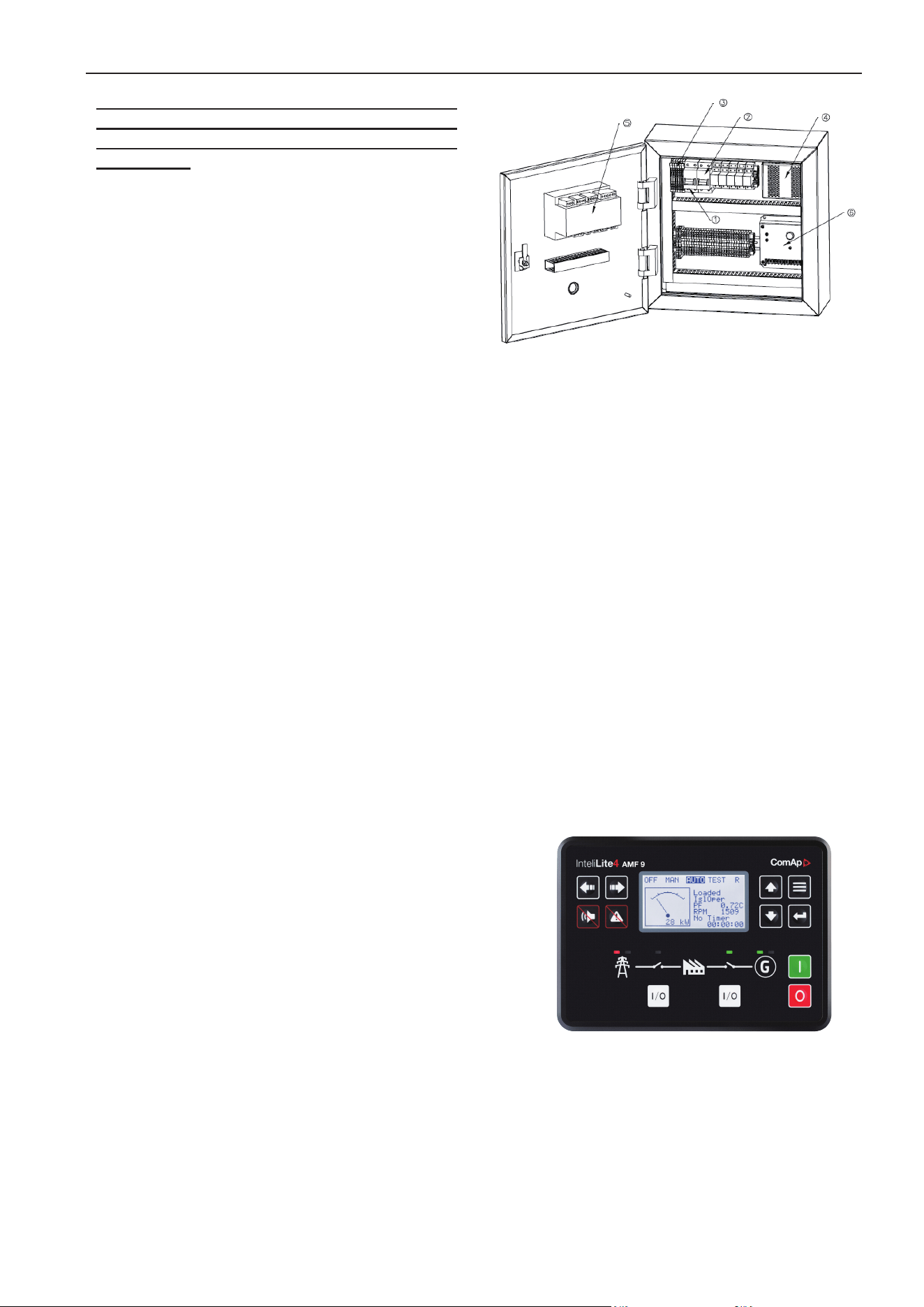
NOModel
1sta
rtpanelpowerswitch
2batterychargerswitch
3fuse
4batterycharger
5controlmodule
6electricgovernor
3.6.2Generatingsetcontrolsystem
To control and monitor the generating set, an
electronic control system has been used.InteliLite 4
AMF 9 model control system is fitted from 10 kVA to
2000 KVA single generator set running system. InteliLite
4 AMF 9 control system is fitted from 10 kVA to 2000
kVA transfer with mains power. Control panel provides a
means of starting and stopping the generating set,
monitoring its operation and output and
automatically shutting down the set in the event of critical
condition arising such as low oil pressure or
highenginetemperature.(ComAPControlsystemplease
readtheComApuser’smanual)
InteliLite 4 AMF 9 controlsystemmoduleintroduction
MainfunctionofInteliLite 4 AMF 9
Thecontrolsystemofdieselgeneratorsetisdeveloped
throughtheuseofmodelInteliLite 4 AMF 9 module, a
special dieselcontroller, made by Czech COMAP
Company. This module is mainly used for auto/
manualstartǦup,protectivestopand manual
auto
switchoverthegeneratorsetpowerand mains
power.
User manual
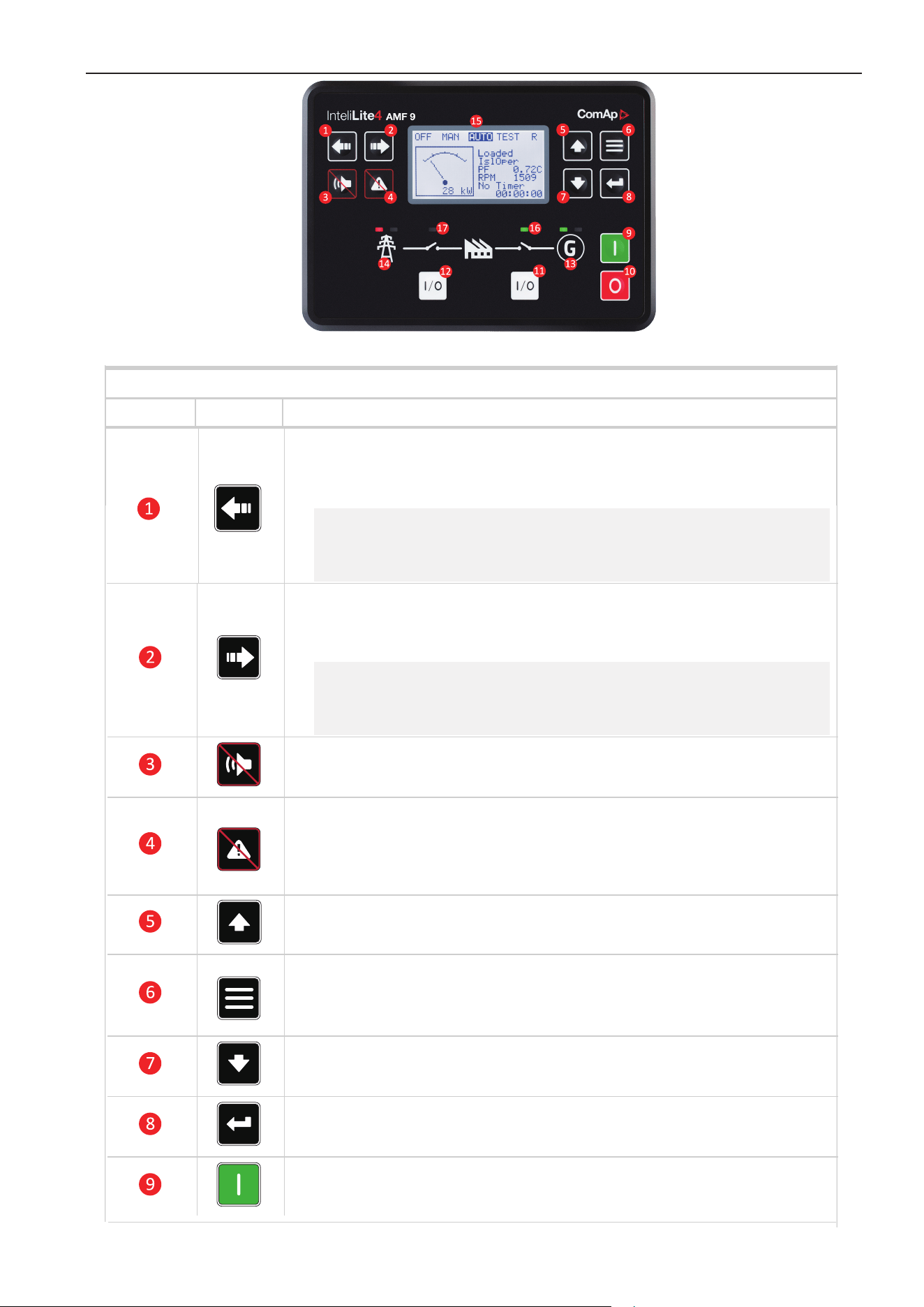
Operator interface of InteliLite 4 AMF 9
Control buttons
Position Picture Description
LEFT button. Use this button to move left or to change the mode. The button
can change the mode only if the main screen with the indicator of currently
selected mode is displayed.
Note: This button will not change the mode if the controller mode is forced
by one of binary inputs listed in the Reference Guide – "Operating modes"
chapter.
RIGHT button. Use this button to move right or to change the mode. The
button can change the mode only if the main screen with the indicator of
currently selected mode is displayed.
Note: This button will not change the mode if the controller mode is forced
by one of binary inputs listed in the Reference Guide – "Operating modes"
chapter.
HORN RESET button. Use this button to deactivate the horn output without
acknowledging the alarms.
FAULT RESET button. Use this button to acknowledge alarms and
deactivate the horn output. Inactive alarms will disappear immediately and
status of active alarms will be changed to "confirmed" so they will disappear
as soon as their reasons dismiss.
UP button. Use this button to move up or increase value.
PAGE button. Use this button to switch over display pages.
DOWN button. Use this button to move down or decrease value.
ENTER button. Use this button to finish editing a setpoint or moving right in
the history page.
START button. Works in MAN mode only. Press this button to initiate the
start sequence of the engine.
GCB button. Works in MAN mode only. Press this button to open or close
the GCB.
MCB button. Works in MAN mode only. Press this button to open or close
the MCB.
15

STOP button. Works in MAN mode only. Press this button to initiate the stop
sequence of the Gen-set. Repeated pressing of button will cancel current
phase of stop sequence (like cooling) and next phase will continue.
GCB button. Works in MAN mode only. Press this button to open or close
the GCB.
MCB button. Works in MAN mode only. Press this button to open or close
the MCB.
Indicators and others
Position Description
GENERATOR status indicator. There are two states – Gen-set OK (indicator is green)
and Gen-set failure (indicator is red). Green LED is on if the generator voltage and
frequency is present and within limits. Red LED starts flashing when Gen-set failure
occurs. After FAULT RESET button is pressed, Red LED goes to steady light (if an alarm
is still active) or is off (if no alarm is active).
MAINS status indicator. There are two states – Mains OK (indicator is green) and Mains
failure (indicator is red). Green LED is on, if mains is present and within limits. Red LED
starts blinking when the mains failure is detected and after the Gen-set has started and
connected to the load it lights permanently until the mains failure disappears.
Graphic B/W display, 132 × 64 px.
GCB Status. Green LED is on if GCB is closed. It is driven by GCB CLOSE/OPEN output
or by GCB feedback signal.
MCB Status. Green LED is on if MCB is closed. It is driven by MCB CLOSE/OPEN
output or by MCB feedback signal.
For more information, please read the included ComAp InteliLite 4 AMF 9 user manual
16

3.7ATScontrolpanel
3.7.1ATSpanelgeneralintroduction
Our customer will need this ATS if generator set is usedforselfǦstartstandbypower.Inordertoachieve full
automatic transfer between mains power and generator set power to guarantee all load present,
ourATSpanelselectthebestATSforallgeneratorset. And to the most possibility to serve our customers’
demand,wepreparetwotypesofATS:MRSandAMF. Besides MRS and AMF can be jointed to a double
standbyATSafteralittlechange,whichisusedfor2 generatorsetsworktogetherstandbymainspower.
Please reference relevant details of ATS for its function,application,operationandsoon.
SaftyAttention:
!Weareverypleasureforyoursupportofourproduct, before you use our ATS please read this instruction
carefully.
We mark three attention parts in accordance with differentsituation:
Danger:
!Ifyoudowrongaction,Personaldeathorotherbig disastermustbehappened.
MovingAttention
Danger:
! When you move ATS by crane or elevator, don’t standbeneaththeATS,toavoidpersonaldeath.
InstallationAttention
Attention:
!Alloperatorsmustbeprofessionalelectrician.
!Cutoffallpowerbeforeinstallation.
!FixscrewinaccordancewithTORPUEstandard.
!PlaceATSonplaneinverticaldirection.
!Don’tinstallATSintheenvironment,wherearehigh temperature,humidororfilledwithcorrosiongas.
!Connectneutral
polewith“N”polewhileyouinstall 4polesofATS.
OperationAttention
Danger:
! Don’t connect energized main circuit or control line withterminal.
Attention:
!IfATSistripping,cutoffpowersource,findproblem andsolveitatfirst.
Our company supply ATS panel should use for AMF series generator control module, from the diagram
youcanseeitisveryeasytoconnectcableandeasy install ATS panel. Our panel can use in AUTO or
17
User manual
18
MANUALstatus.
Manualstatusoperation:
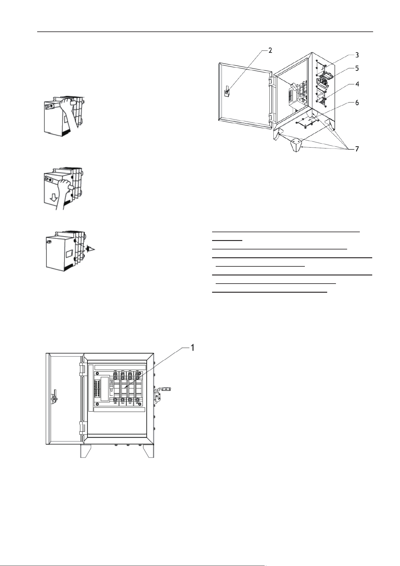
Step1
Youshouldcheckthegeneratorcontrolmodulesetin
MANUAL status, then use the operate handle insert
theswitchaxis.
Step2
Operatingdirectionofthearrow
Step3
Checkthepositionon‘A’or‘B’.
AUTOstatusoperation
You can connect th
e special cable connector with
generator set. Then set the generator module in
AUTO,that is OK!(detail operate step refer module
controlsystem)
ATSPANELintroduction
NoMODEL
1ATSswitch
2panellock
3mainspoweroutputhole
4generatorpoweroutputhole
5communicatewithgeneratormoduleport
6
loadpowercableoutput
7panelongroundleg
Maintenance,inspectorexchangepartsattention:
Attention:
!Alloperatormustbeprofessionalelectrician.
! Turn switch on “OFF” position, make sure main line
orcontrollineisn’tenergizing.
! When you want to inspect inside part, make sure
power“A”B”isoff,to avoidfingerinjury.
!Fixscrewofterminalinelectricalway.

User manual
19
4 Maintenance
4.1Generaloutline
For different types of generator sets, users need to
refer to the matched engine’s operation and
maintenance manual to implement correct
maintenanceoperation.
Inordertoobtainmaximumoperationsafetyandlife
expectancy of the generator sets, periodic
maintenanceisveryimportant.Strictlyobservanceof
thetermsongeneratorset’smaintenancecanensure
generator set’s performance and reduce its damage
toenvironment.
Correctly identify and strictly observe the labels
(drawings, words and warnings etc.) On diesel
generator sets can be of great help to correct
maintenanceandsafeoperations.
Maintenance of the generator sets shall be made
when it has been stopped and the cable which
connecttothenegativepolarofthebatteryshallbe
disǦconnectedsothattoensurethegeneratorsetwill
notmistakenlystart.
4.2Engine
Eachtimebeforestarttheengine
!Checklubricantoillevel
!Checkcoolantlevel
!Checkairfilterindicator
! Check the ventilation of radiator and ambient
environment
!Checkengine’stransmissionbelt
!Checkfuelsupplystatus
Generator sets which run frequently need to be
checked one time every 6 to 8 hours. Backup
generator sets need to be checked once more after
beingstopped.
Depends on the new generator set’s running status,
when it is necessary, within 100 to 300 Hours,
followingactionsshallbetaken:
!Checkthevalveclearance
!Checkthefuelinjector
Foreach0~50hoursofrunning
! Discharge the water remained in the oilǦwater
separator
! Check the battery’s electrolyte level (except
maintenancefreebattery)
For each 50~600 hours of running or at least each 12
months
!Changelubricantandlubricantfilter
!Becausethequalityoflubricantoil,sulfurcontentof
the fuel, and lubricant consumption rate of each
engine is different, the interval
for lubricant oil
changeforeachgeneratorsetwillbedifferent.When
change the lubricant oil, at the same time oil filter
needstobechanged,otherwisethechangeofoilwill
becomemeaningless.Onthecontrary,ifthelubricant
oilremainsingoodstatus,wecanfilterthelubricant
muchbetterbychangetheoilfilter.
! Change fuel filter, clean or change first stage fuel
filter core, oil water separator’s core (some of the
generator sets have), check and organize fuel pipes
arrangement.
! The change interval of above fuel filter (core)
depends on the quality of fuel (if it contains many
impurity), the fuel adding method is reasonable or
not, the fuel tank is cleanedperiodically or not
(contaminant discharge). Once the color of engine
exhaust air is found to be abnormal and the output
power decrease, first the fuel system needs to be
checked.
For
each400hoursofrunning
!Checkandadjustthetransmissionbeltandchangeit
whennecessary
!Checkandcleanradiatorcore
!Dischargedepositinthefueltank
Foreach800hoursofrunning
!Checkiftheturbochargerhasleakage
!Checkiftheairinletpipeshasleakage
Foreach1200hoursofrunning
!Adjustvalveclearance
Foreach2000
hoursofrunningoratleast24months
! Change air filter (depend on ambient air quality,
decideifthisneedtobechangedearlier)
! Change coolant and coolant filter (some generator
setshave)
!Thoroughlycleanradiatorcoreandwaterpath
Foreach2400
hoursofrunning
!Checkfuelinjector
!ThoroughlycheckandcleanturboǦcharger
!Comprehensivelycheckengineequipment

User manual
20
4.3Alternator
Insideandoutside of the alternatorshallbe cleaned
periodically. And the frequency of cleaning depends
on the generator set’s ambient environment. When
the cleaning becomes necessary, following
procedurescanbefollowed:cutoffallofthepowers,
wipeoffthedirt,contaminant,oilstain,waterorany
other liquid from the surface. The ventilation mesh
alsoneedstobecleaned.The adhesivenessofthese
materialstothecoilswillcausethecoilsoverheator
damagetheinsulation.
The dirt and contaminant need to be absorbed by
dust collector. Please don’t use air blow or high
pressurewaterspraytocleanthealternator.
The humidity of alternator will decrease insulation
resistance.Thealternatorshallbedried.Pleaserefer
to Alternator’s Operation and Maintenance Manual
forthemethodofdryinganddetailedmaintenance.
4.4Controlpanel
Dailymaintenance for thecontrol panel shallensure
thecleannessofitssurface,maketheindicatormore
clearandeasyforreading,andtheoperationbutton
flexibleandreliable.
During the generator set’s running period, vibration
willcause theshiftof“0”positionintheinstrument
of control panel and loose of tightened parts, and
therefore periodically check the instrument of the
control panel and parts and cable’s connections are
veryimportant.
Repair for the control panel can only be done after
thorough learning of the principle of this control
panel (please refer to Control Panel Operation
Manualfordetails)
4.5Startbattery
Batterieswhichhavebeenstoredinalongtimeshall
be properly charged before being used, so that to
ensure normal capacitance of the battery.
(Densimeter can be used to check the actual
capacitanceofthebattery)
Normal operation and battery charging will cause
some water inside of the battery being vaporized.
And therefore constant fluid infusion is needed.
Before fluid infusion, first the contaminant around
the adding hole shall be cleaned so that to avoid
them falling into the battery. Then open the adding
hole,add proper amount of distilled water or purified
water. Do not add too much (shall be according to
the indicating line in the battery polar plate),
Otherwise the inside electrolyte will overflow from
theaddingholewhenthebatteryisunderdischarge
or charging, which will cause contamination to the
ambientmaterialandenvironment.
Pleasedonotusethebatteryto start thegenerator
set under low temperature because the battery
capacitance can not output normally under low
temperature, and long time discharge may cause
batterymalfunction(crakeorexplode).
Warning:
! The battery of the back up generator set shall be
periodically maintained and charged. Itis suggested
thatuserscanbuyfloatingchargerforthebattery.
4.6Maintenancerecord
Each time after maintenance, users shall make
detailedrecordforthemaintenancejob.
Warning:
! Complete maintenance record provides evidence for
userstomaintainthegeneratorset,andatthesame
time is a precondition for lawful after sales service
(warranty).
For example: Maintenance record (Refer toAppendix
FandG)

User manual
21
5CheckforMalfunction
5.1Generaloutline
There are many factors which may cause the
generatorset’smalfunction,andthemalfunctionsare
usually closely related to each other. This section
mainly summarize and list the possible malfunctions
ofgeneraldieselgeneratorsets.Thisisjustforuser’s
reference when they try to eliminate the
malfunction(s). (Especially important for new
generatorset’scustomer)
One thing must to be emphasized: most of the
malfunctions are caused by user’s improper
installation, operation, and maintenance. Users are
entitledtodoubtthatthemalfunction(s)iscausedby
the generator set’s manufacture failure, but this
conclusion shall be based on correct installation,
operation and periodically maintenance. Otherwise,
we can not assure you the normal operation of the
generatorsetandthedeservedaftersalesservice.
5.2Malfunctionchecklist

We
Company name:
Postal address:
Postcode:
City:
Telephone number:
E-Mail address:
Declaration of Conformity
In accordance with EN ISO 17050-1 :2010
Genpower Ltd
Isaac Way, Pembroke Dock
SA72 4RW
Pembrokeshire
01646 687 880
declare that the DoC is issued under our sole responsibility and belongs to the following product:
Model/Product: DHY9KSEm, DHY11KSEm, DHY18KSEm, DHY22KSEm, DHY28KSEm,
DHY35KSEm, DHY53KSEm, DHY11KSE, DHY14KSE, DHY22KSE, DHY28KSE,
DHY34KSE,DHY45KSE,DHY65KSE,DHY85KSE,DHY125KSE
Description 1500rpm Diesel Generator
Object of the declaration (identification of apparatus allowing traceability; it may include a colour image of sufficient
clarity where necessary for the identification of the apparatus):
See Below
The object of the declaration described above is in conformity with the relevant Union harmonisation legislation:
2008 (S.I. 2008/1597) Machinery Directive
the Eletromagnetic Compatibility Regulations 2016 of
United Kingdom ( 2014/30/EU EMC Directive )
2000/14/EC Noise Emissions Directive
97/68/EC NRMM Emissions Directive
The following harmonised standards and technical specifications have been applied:
Title, Date of standard/specification:
EN ISO 8528-13:2016
EN 55012:2007+A1
EN 61000-6-1:2019
Additional information:
Signed for and on behalf of:
Genpower Ltd
Place of issue
09/11/2022
Date of issue
Roland Llewellin,
Managing Director
Name, function, signature
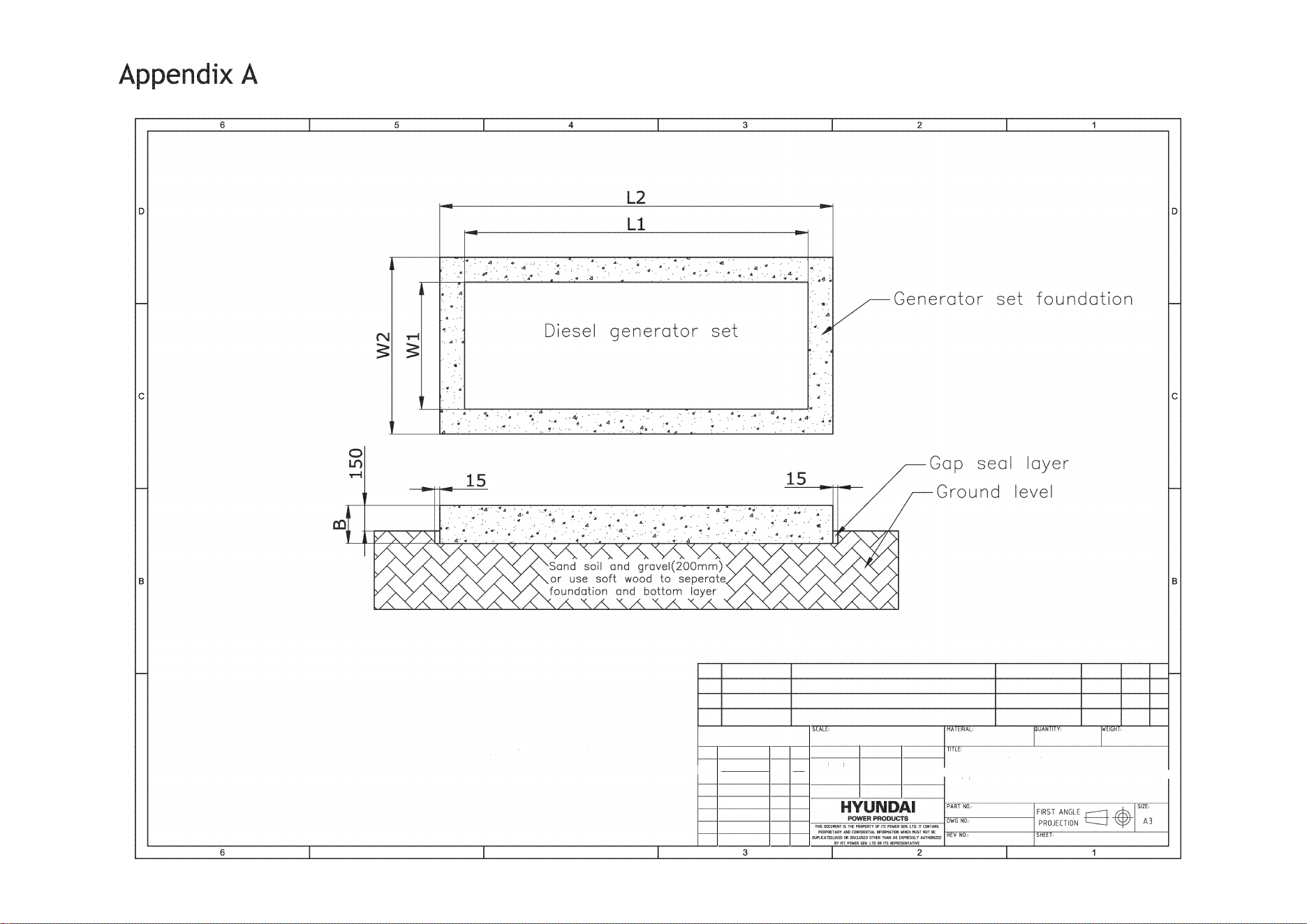
A
NOTE:
L2=L 1 +400mm
W2=W1 +400mm
B=2M
/
L2*W2*D
(D: 2
3
22kg/
m
3)
Generator foundation design
5 4
ORDER
PART NO.
DESCRIPTION
MATERIAL HASS
aTY REV
SCALE
2010
Generator foundation design
-----+
DR
A
W
N
--
---
i,u=se=□�o,�
-------
--------
A
CHECKED
APPROVED
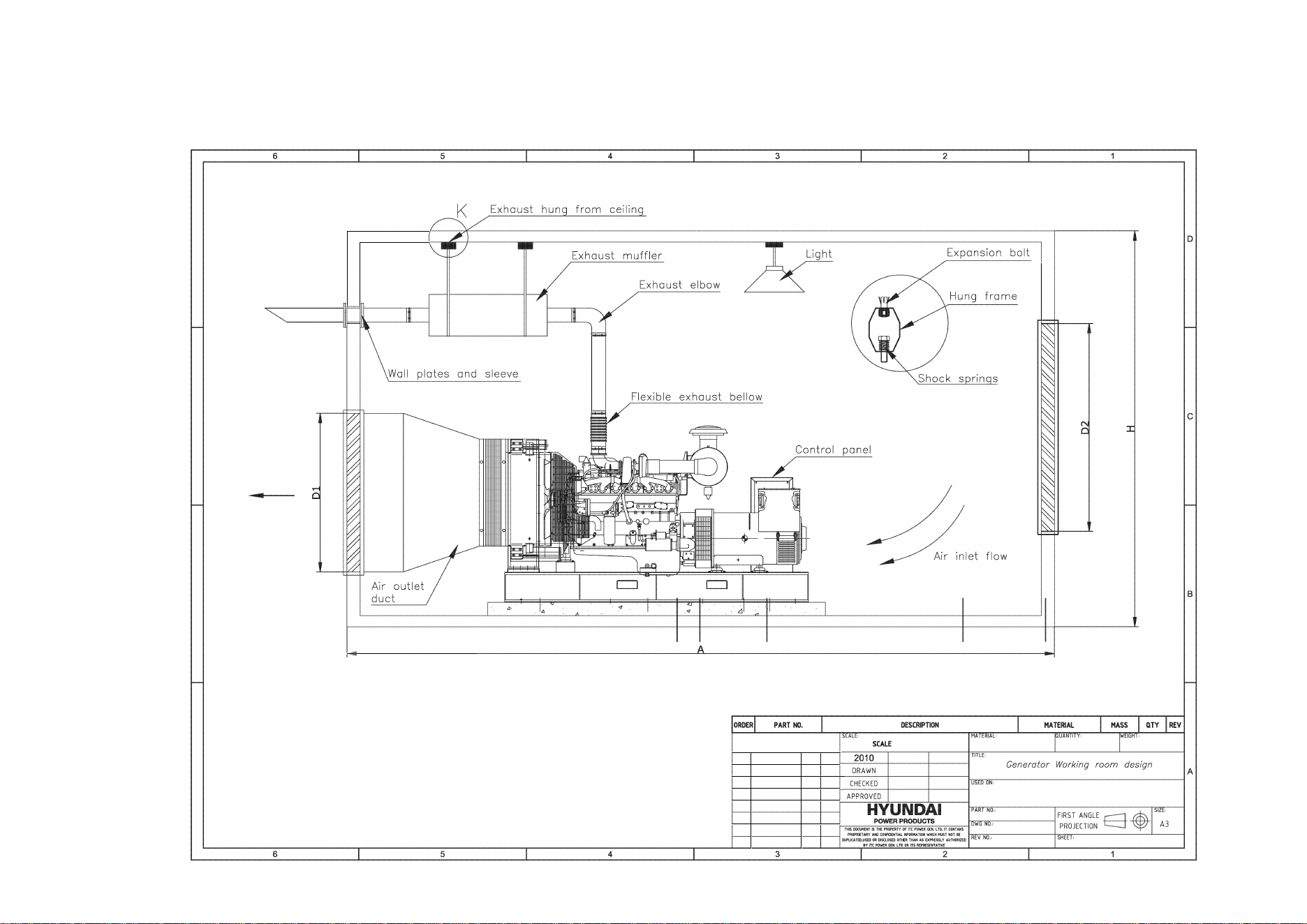
Appendix B
D
C
-
-
-
Air outlet flow
B
A
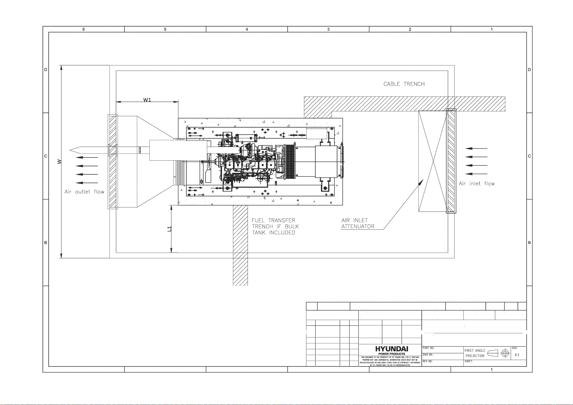
A
6 5 4
ORDER PART NO. DESCRIPTION
SCALE
SCALE
2010
MATERIAL
MATERIAL QUANTITY
TITLE:
MASS
WEIGHT
QTY REV
Generator rking room design
------
D
R
A
W
N
-----==-----------------
A
CHECKED
USED ON
A
PP
R
OVE
D
3 2
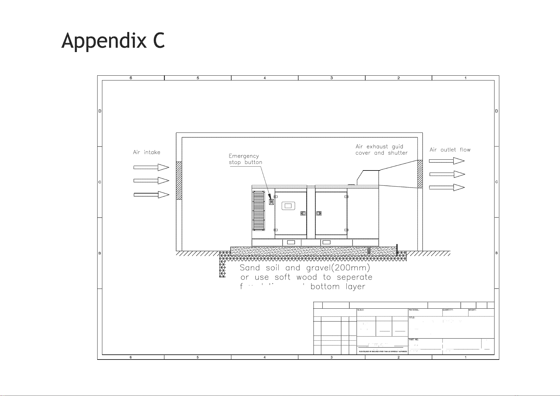
ounoo1on ono
A
ORDER PART NO.
SCALE
2010
DESCRIPTION MATERIA.L MASS TY REV
Generator Working room design
---
-
:H:�:EN:D
--
---
u
SED
�
O
m
N
---
---
---
-----
A
r-----�=�----
APP
RO
VED
Cano Generator
HYUNDAI
SIZE·
FIRST ANGLE
™"'""m����:.��'�?�,rrco,r
.. ,
'o~we~,-o
---
-
P
RO
J
E
CTION � A3
f-
---
-
,.
"FIETARYANDCOlffllElffW.lll'MATIOWlilCSTNOTDE
=,v�,o�-----,H=m�-----�
-
SYITtPERGELTDOlTSREFEIENTATl'IE
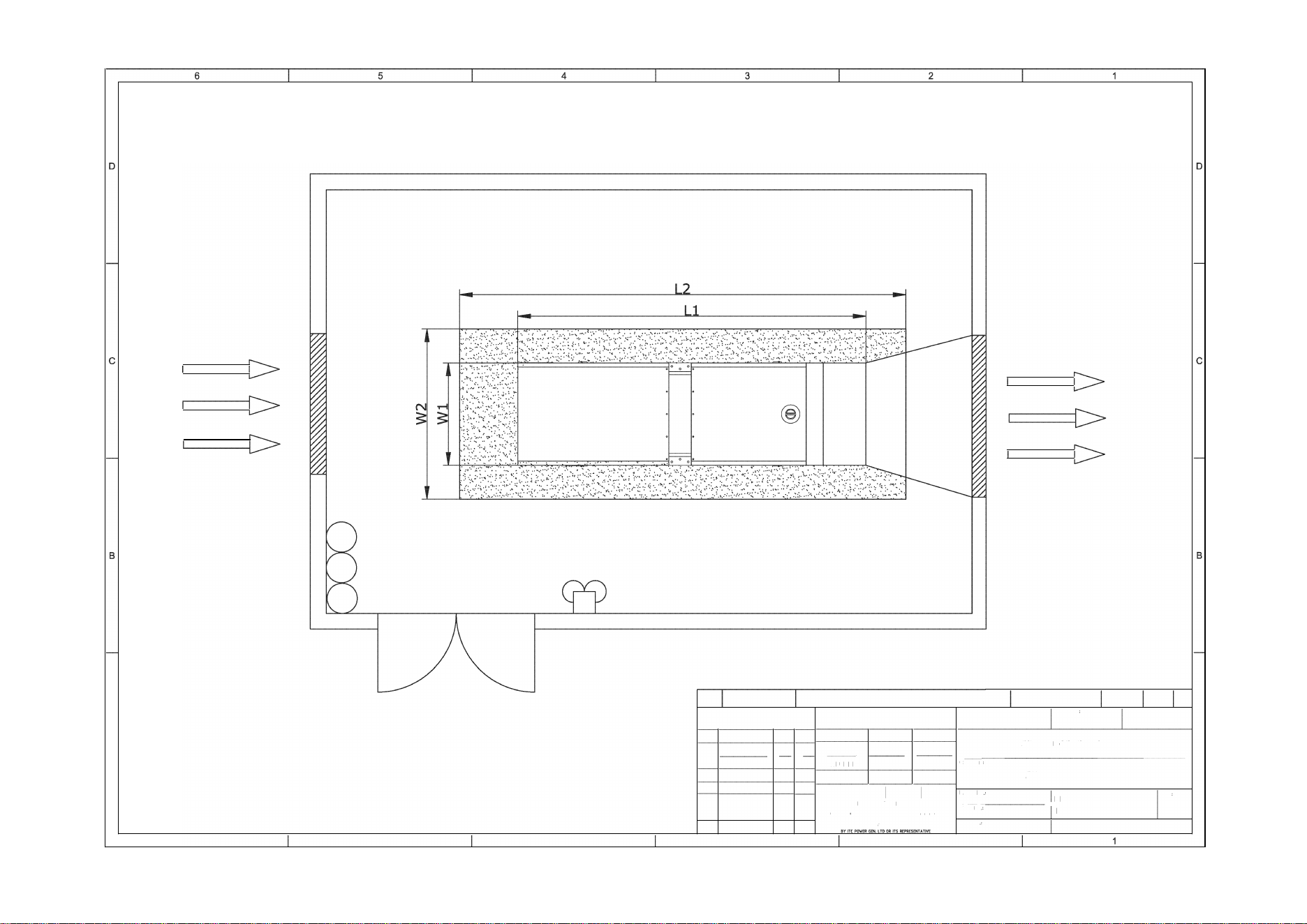
A
6 5
4
ORDER PART NO. DESCRIPTION
SCALE: MATERIAL:
SCALE
2010
TITLE:
MATERIAL
QUANTITY
MASS
WEIGHT:
OTY REV
DRAWN
Generator Working room design
A
,
----
-
-
C
H
E
CK
E
D
,
---
---
6
us~rn�o-N
-----------------
APPROVED
Canopy Generator
,,----,-,-,,�.,,�oo�co�, .. �,H�.,!p:��,,:��
,
?,r�,��G!,��,.�,,�,,_�,.� .. :�:'�,'�,:�'-----
F
�:��E��l��
E
S1:3
3
PROPRIETARY AND C°"FIDENTIALl�OR�ATIONWIICHMUST NOT BE
OUPLlcATEO,USEODR OIS(LOSEO OTHER THAN AS EXPRESSLYAIITHORIZ[O
2
REV NO SHEET:
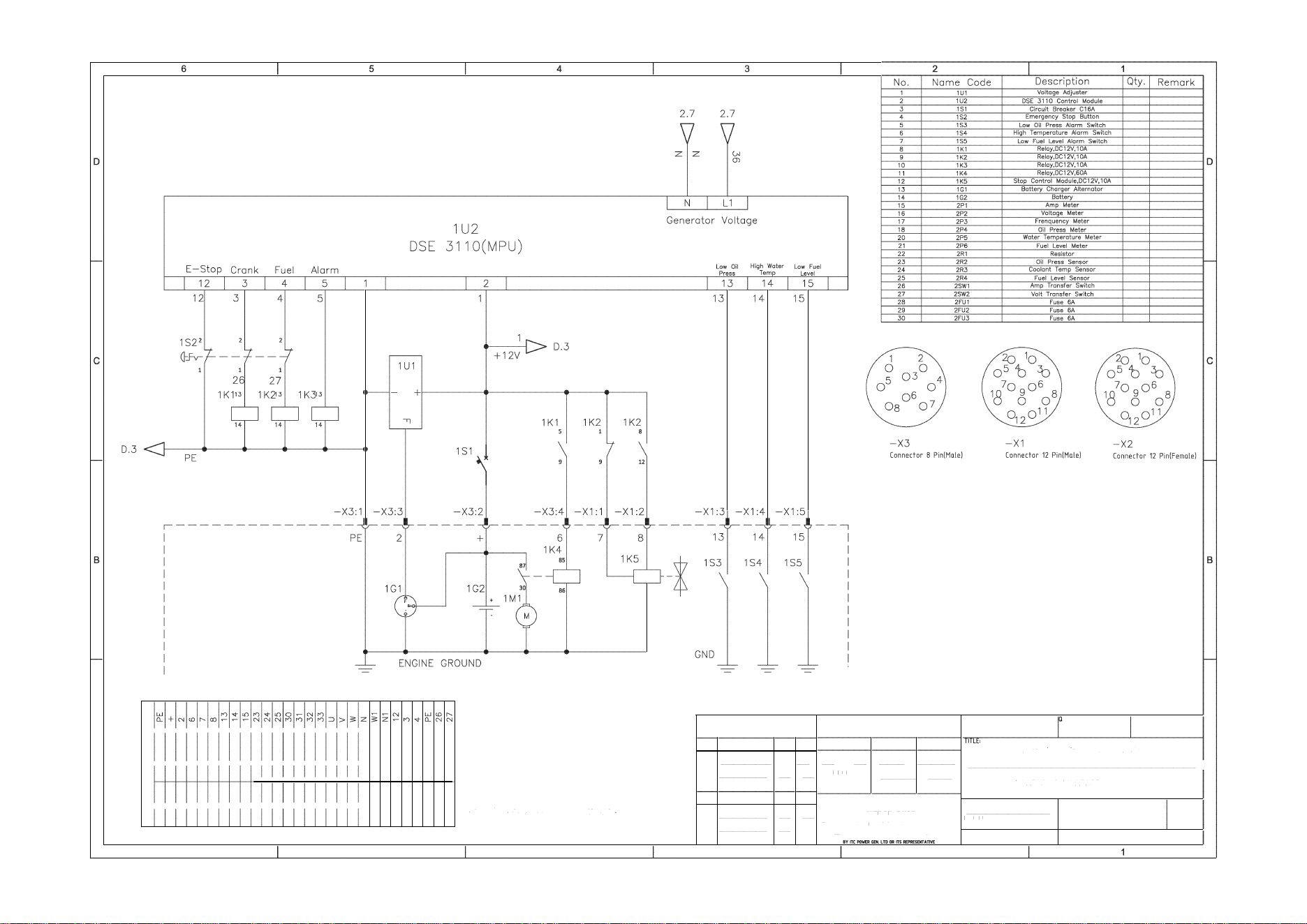
A
I
L-------------------------------------------------------�
HH
O
�Nn��Nn��w��Nn��w�
��
h
����������NNNNNNNN
Uxxxxxxxxxxxxxxxxxxxx
w
z
�
Z�Nn��w�
mo�Nn��m�mo�Nn��m�
Q
����������NNNNNNNNN
u
I
X
HHH�
6 5
Connector: No.23,24,25 use for canopy type
4
SCALE: MATERIAL, UANTITY, WEIGHT,
SCALE
2011
DATE
NAME
Electrical orcuif dmgram(DSE3710 Module/
-----t---+
D
:
R
A
W
N
-
+-----L __________________
_
J A
---
-
+
-
+
-
C
HE
C
K
ED
---
--
U
SE
D ON,
APPR
O
VED
DHYIOKKSE -DHY60K KSE
HYUNI
PART NO.:
F
IRST AN
GL
E
S
IZE
,
----
+
-
+
-
™--•-�•- ,-,.:.,.w:::,�:,:,�.��,�!:_,-,m-,-,.-�-
M
, ,-w-, -,,-., _____
_
,
PR
OJECTION V A3
----
-
- PRCPRIETARY AND CIDENTIAL ORMATION WIICHNUSTNOTBE
DlPUCATED,USED CDISD.OSEDQTRTH AN AS EXPRES.YAUTHDRI
3 2
REV NO.,
SHEET,
l- f
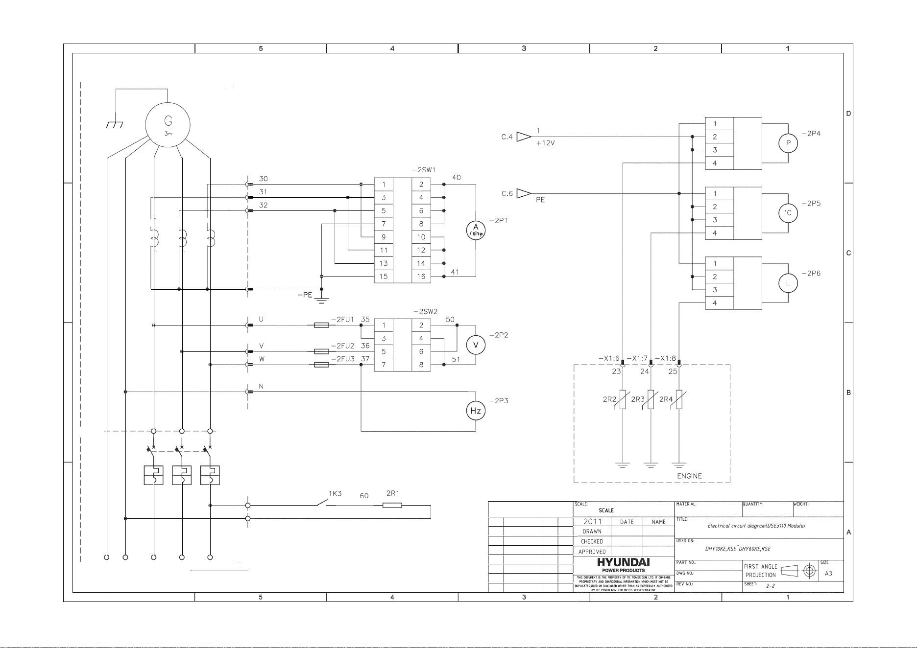
D
C
B
A
6
,------------------7
-GND
GND
N
--
GND
N
ALTERNATOR I
u
V
w
2CT1
I r
1
2CT2 I r
1
2CT3 Ip,
IP
2
IP
2
I
P
2
u
V w
-X2:1
-X2:2
-X2:3
-X2:4
I
I
I
I
I
I
I
I
I
I
I
I
-X2:5
I
-X2:6
-X2:7
I
-X2:8
I
I
---7
I
2K6
I
I
W1
N1
I
I
I
I
I
I
I
I
L
__
__
__
__
__
__
BUSB
AR
PA
�
E
6
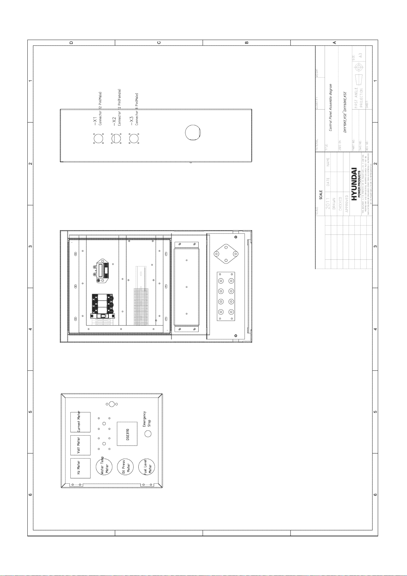
0
m
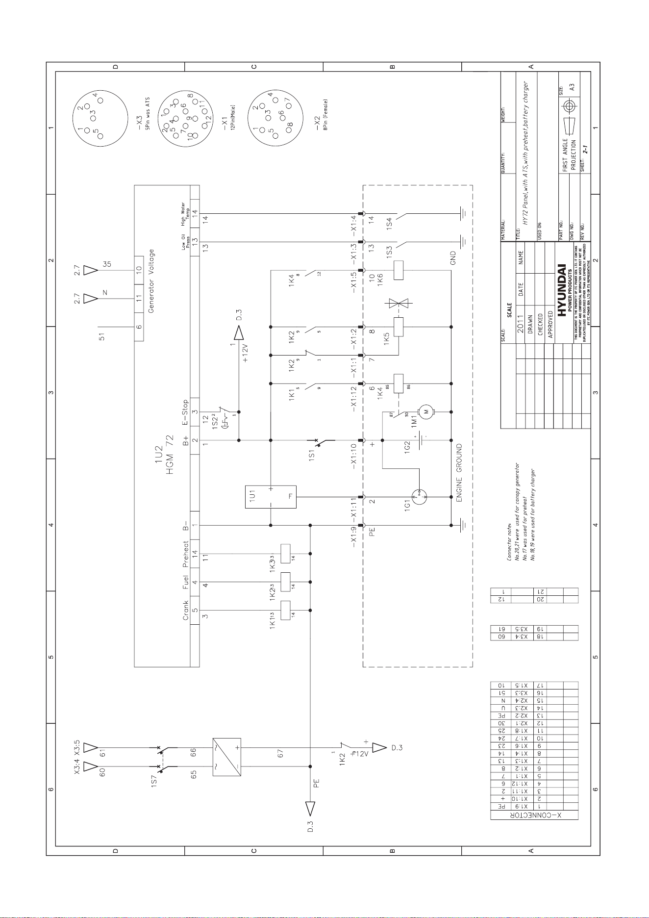
DHY10KE,KSE~DHY250KE,KSE
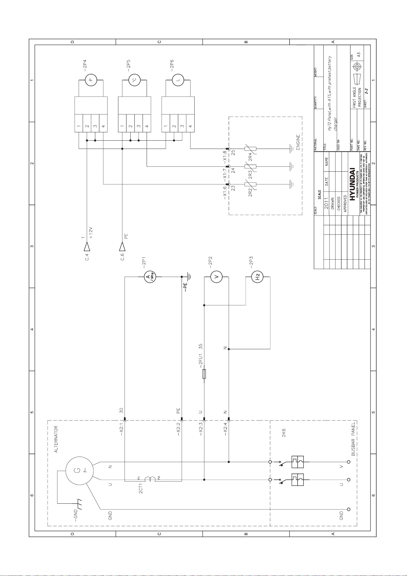
DHY10KE,KSE~DHY250KE,KSE
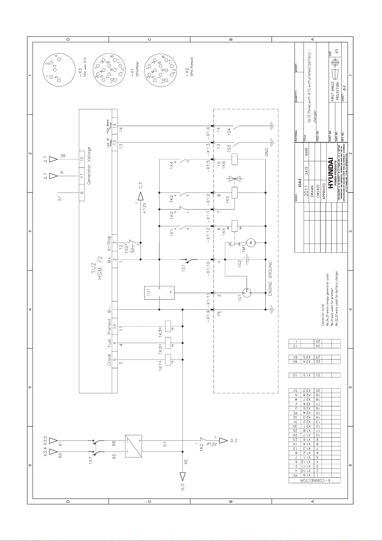
DHY10KE,KSE~DHY250KE,KSE
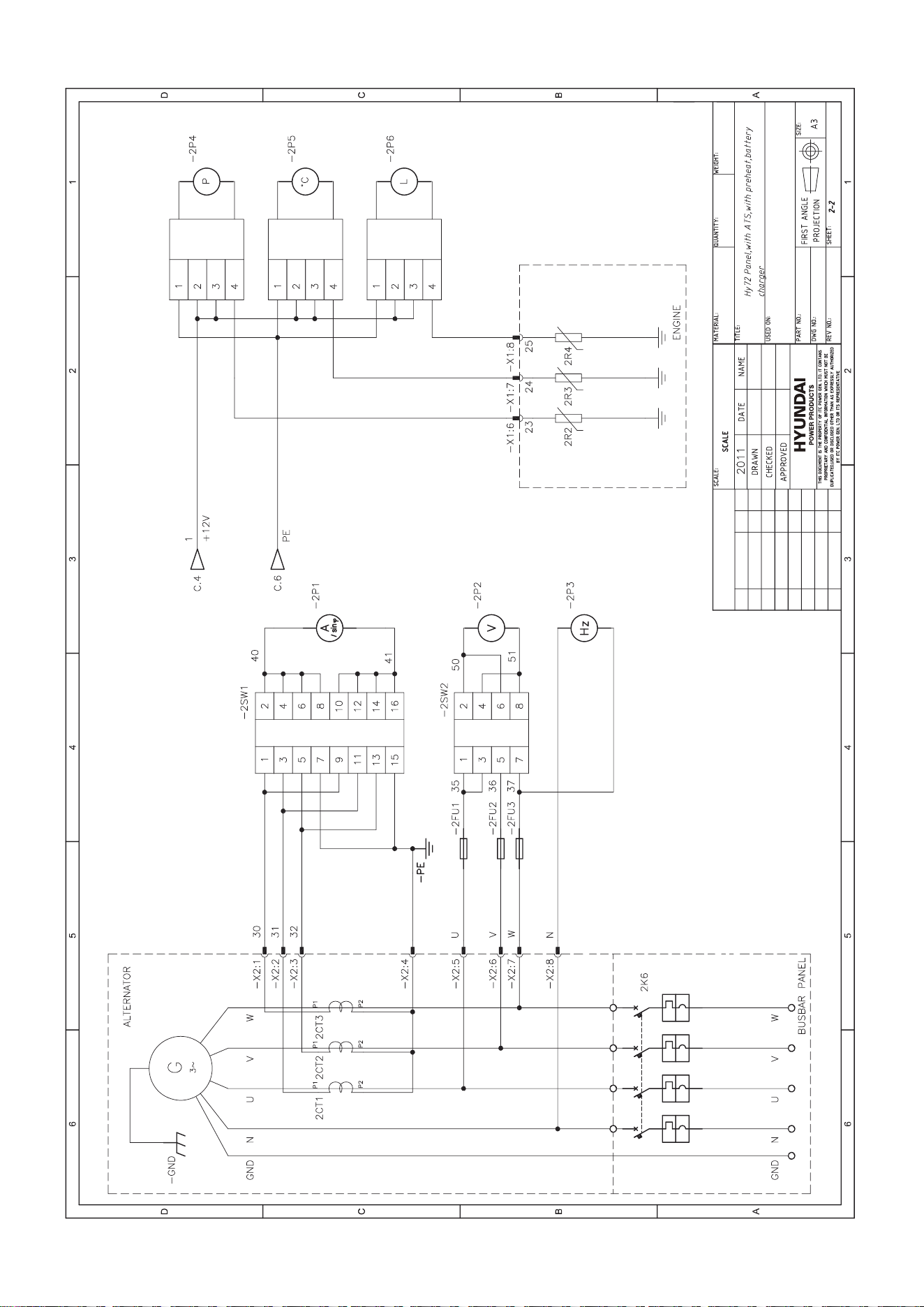
DHY10KE,KSE~DHY250KE,KSE
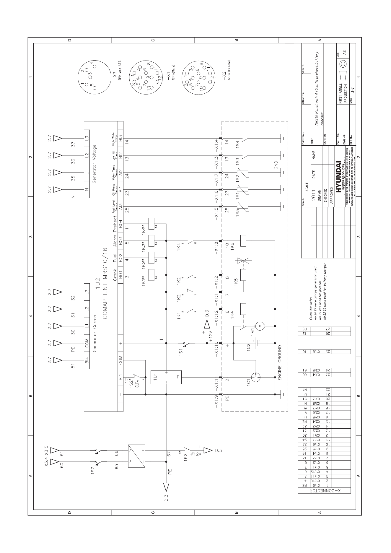
DHY10KE,KSE~DHY250KE,KSE
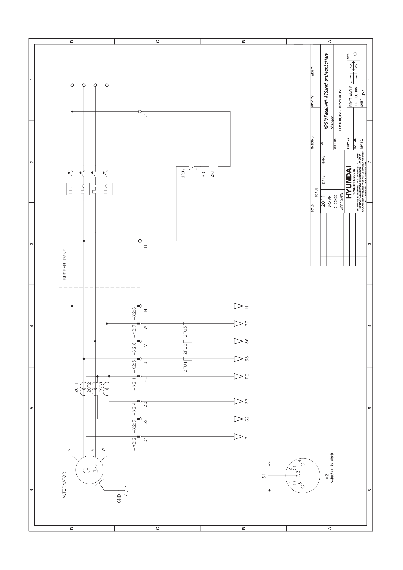
DHY10KE,KSE~DHY250KE,KSE
APPENDIX E
1
2
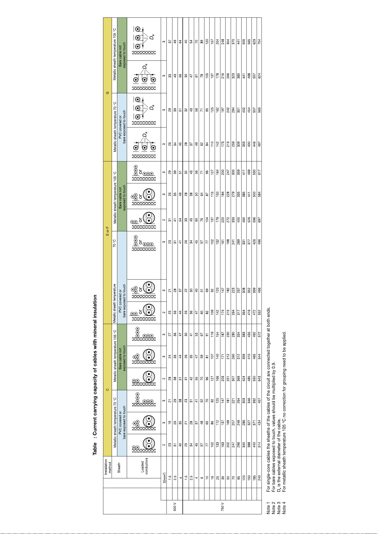
3

APPENDIX F
Generator set running record
TIME ENGINE PARAMETER GENERATOR PARAMETER
IF RECORD
FOR
MALFUNCTION
IS AVAILABLE
OPERATOR REMARK
Start/stop
generator
set time
Accumulated
running
time
Oil
pressure
Temperature Voltage Current Frequency Power
APPENDIX G
Maintenance Record
Maintenance Time: SN:
Generator set model: Engine model: Alternator Model:
Generator set serial No.: Engine serial No.: Alternator serial No.:
Accumulated running hours: Maintenance cycle:
Reasons for maintenance (periodic maintenance or malfunction maintenance)
Inspection and repair
Inspection and adjustment
Change of parts
Clean and maintenance
Others
Conclusion for maintenance:
Maintenance staff signature:
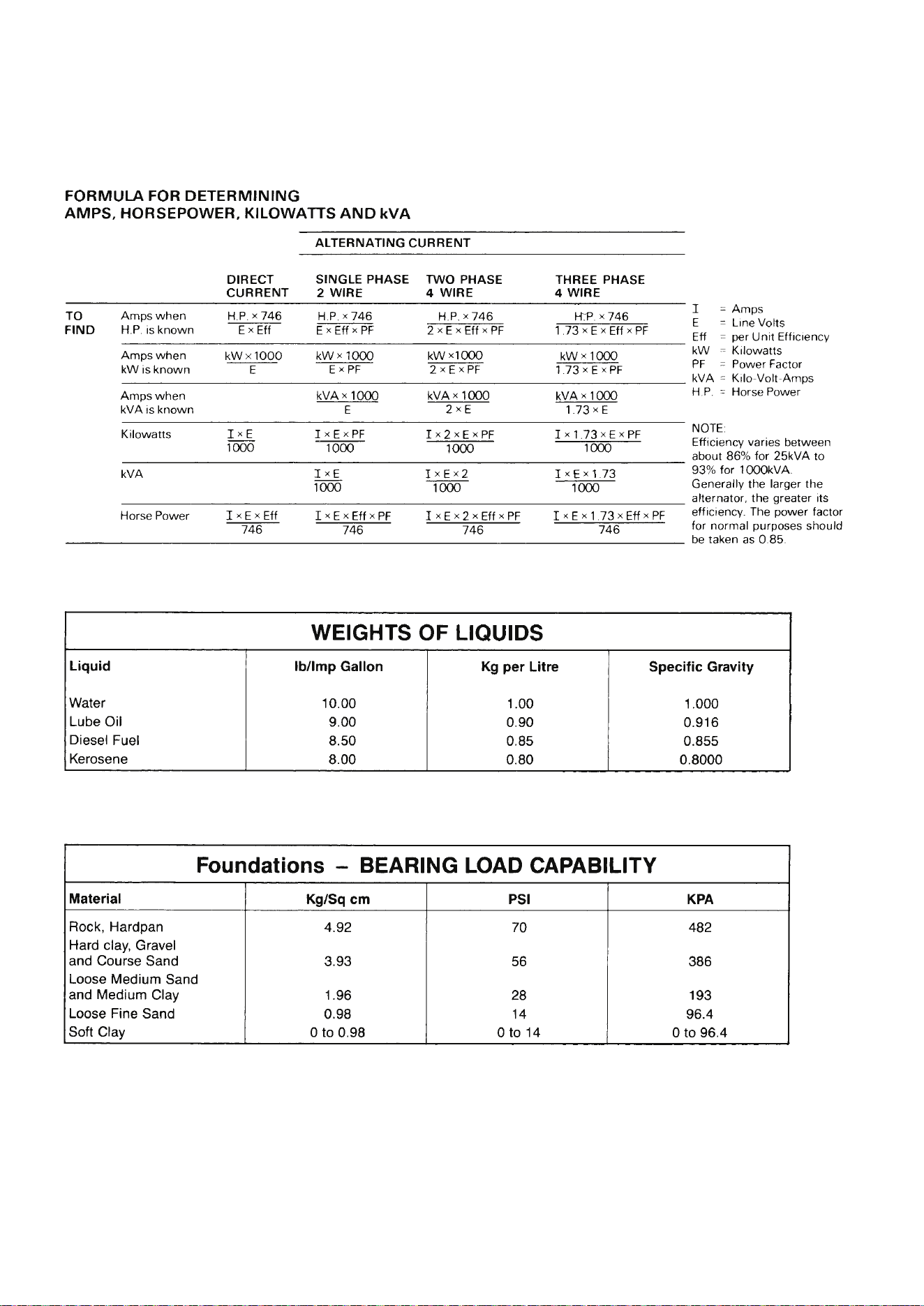
APPENDIX H

For Inquiries, Please Contact:
GENPOWER LTD
Isaac Way, London Road, Pembroke
Dock, UK, SA72 4RW.
T: +44 (0) 1646 687 880
www.hyundaipowerproducts.co.uk
Imported / Distributed by Genpower Ltd for
the United Kingdom & Ireland
Licensed by Hyundai Corporation Holdings, Korea