
DLC:GHB6CJ6A
;DGBD9:AHB6CJ;68IJG:96;I:G%)$&'
BD9:AL&-'+
&=EL6AA"BDJCI
9JHI8DAA:8IDG
E]dcZ/(+%,()"()-'Dca^cZIZX]c^XVaHjeedgi/iZX]"hjeedgi5h]de[dm#W^o
8DENG><=IB6N!'%&'7NLDD9HID8@>CI:GC6I>DC6A!>C8#
L6GC>C</CDEDGI>DCD;I=>HB6CJ6AB6N7:G:EGD9J8:9>C6CNH=6E:DG;DGBL>I=DJI
I=:LG>II:C6EEGDK6AD;LDD9HID8@>CI:GC6I>DC6A!>C8#
HI&)*%.Eg^ciZY^cIV^lVc
K_`jdXelXcgifm`[\jZi`k`ZXcjX]\kp`ejkilZk`fejfek_\gifg\ij\klg#
fg\iXk`fe#dX`ek\eXeZ\#Xe[j\im`Z\f]k_`jdXZ_`e\&kffc%JXm\k_`j
[fZld\ek#i\]\ikf`kf]k\e#Xe[lj\`kkf`ejkilZkfk_\ifg\iXkfij%
=X`cli\kfi\X[#le[\ijkXe[Xe[]fccfnk_\`ejkilZk`fej`ek_`jdXelXc
dXpi\jlck`e]`i\fij\i`fljg\ijfeXc`ealipÇ`eZcl[`e^XdglkXk`fe#
\c\ZkifZlk`fe#fi[\Xk_%
K_\fne\if]k_`jdXZ_`e\&kffc`jjfc\cpi\jgfej`Yc\]fi`kjjX]\lj\%
K_`ji\jgfej`Y`c`kp`eZcl[\jYlk`jefkc`d`k\[kfgifg\i`ejkXccXk`fe`e
XjX]\\em`ifed\ek#g\ijfee\ckiX`e`e^Xe[ljX^\Xlk_fi`qXk`fe#
gifg\i`ejg\Zk`feXe[dX`ek\eXeZ\#dXelXcXmX`cXY`c`kpXe[Zfdgi\$
_\ej`fe#Xggc`ZXk`fef]jX]\kp[\m`Z\j#Zlkk`e^&jXe[`e^&^i`e[`e^kffc
`ek\^i`kp#Xe[k_\ljX^\f]g\ijfeXcgifk\Zk`m\\hl`gd\ek%
K_\dXel]XZkli\in`ccefkY\_\c[c`XYc\]fi`ealipfigifg\ikp
[XdX^\]ifde\^c`^\eZ\#`dgifg\ikiX`e`e^#dXZ_`e\df[`]`ZXk`fejfi
d`jlj\%
Jfd\[ljkZi\Xk\[Ypgfn\ijXe[`e^#jXn`e^#^i`e[`e^#[i`cc`e^#Xe[
fk_\iZfejkilZk`feXZk`m`k`\jZfekX`ejZ_\d`ZXcjbefnekfk_\JkXk\f]
:Xc`]fie`XkfZXlj\ZXeZ\i#Y`ik_[\]\Zkjfifk_\ii\gif[lZk`m\_Xid%
Jfd\\oXdgc\jf]k_\j\Z_\d`ZXcjXi\1
C\X[]ifdc\X[$YXj\[gX`ekj%
:ipjkXcc`e\j`c`ZX]ifdYi`Zbj#Z\d\ekXe[fk_\idXjfeipgif[lZkj%
8ij\e`ZXe[Z_ifd`ld]ifdZ_\d`ZXccp$ki\Xk\[cldY\i%
Pflii`jb]ifdk_\j\\ogfjli\jmXi`\j#[\g\e[`e^fe_fnf]k\epfl
[fk_`jkpg\f]nfib%Kfi\[lZ\pfli\ogfjli\kfk_\j\Z_\d`ZXcj1
Nfib`eXn\ccm\ek`cXk\[Xi\X#Xe[nfibn`k_Xggifm\[jX]\kp\hl`g$
d\ek#jlZ_Xjk_fj\[ljkdXjbjk_XkXi\jg\Z`Xccp[\j`^e\[kf]`ck\i
flkd`ZifjZfg`ZgXik`Zc\j%

-1-
Df[\cN(/)-=fiDXZ_`e\jD]^%J`eZ\+&()
@EKIF;L:K@FE
@EKIF;L:K@FE%%%%%%%%%%%%%%%%%%%%%%%%%%%%%%%%%%%%%)
Woodstock Technical Support .................. 2
Controls & Features ............................. 5
J8=<KP%%%%%%%%%%%%%%%%%%%%%%%%%%%%%%%%%%%%%%%%%%%%%%%-
Standard Machinery Safety Instructions ...... 6
Additional Safety for Dust Collectors ......... 8
<C<:KI@:8C%%%%%%%%%%%%%%%%%%%%%%%%%%%%%%%%%%%%%%%%%0
Circuit Requirements ............................ 9
Grounding Requirements ...................... 10
Extension Cords ................................ 10
J<KLG%%%%%%%%%%%%%%%%%%%%%%%%%%%%%%%%%%%%%%%%%%%%%% ()
Unpacking ....................................... 12
Inventory ........................................ 12
Machine Placement ............................ 13
Assembly ......................................... 14
Collection System .............................. 15
Power Connection .............................. 17
Test Run .......................................... 18
FG<I8K@FEJ%%%%%%%%%%%%%%%%%%%%%%%%%%%%%%%%%%%%%%% (0
General .......................................... 19
Machine Storage ................................ 19
Accessories ...................................... 20
D8@EK<E8E:<%%%%%%%%%%%%%%%%%%%%%%%%%%%%%%%%%%%% ))
Schedule ......................................... 22
Lubrication ...................................... 22
Bag Cleaning .................................... 22
J<IM@:<%%%%%%%%%%%%%%%%%%%%%%%%%%%%%%%%%%%%%%%%%%%% )*
General .......................................... 23
Impeller Tightening ............................ 23
Electrical Safety Instructions ................. 24
Wiring Diagram ................................. 25
Troubleshooting ................................. 26
G8IKJ%%%%%%%%%%%%%%%%%%%%%%%%%%%%%%%%%%%%%%%%%%%%%% )/
System ........................................... 28
Label Placement ............................... 29
N8II8EKP%%%%%%%%%%%%%%%%%%%%%%%%%%%%%%%%%%%%%%%% **
:fek\ekj
-2-
Df[\cN(/)-=fiDXZ_`e\jD]^%J`eZ\+&()
@EKIF;L:K@FE
Nff[jkfZbK\Z_e`ZXcJlggfik
This machine has been specially designed to provide many years of trouble-free service. Close attention
to detail, ruggedly built parts and a rigid quality control program assure safe and reliable operation.
Woodstock International, Inc. is committed to customer satisfaction. Our intent with this manual is to
include the basic information for safety, setup, operation, maintenance, and service of this product.
We stand behind our machines! In the event that questions arise about your machine, please contact
Woodstock International Technical Support at (360) 734-3482 or send e-mail to: k\Z_$jlggfik7j_fg]fo%
Y`q. Our knowledgeable staff will help you troubleshoot problems and process warranty claims.
@EKIF;L:K@FE
If you need the latest edition of this manual, you can download it from _kkg1&&nnn%j_fg]fo%Y`q.
If you have comments about this manual, please contact us at:
Nff[jkfZb@ek\ieXk`feXc#@eZ%
8kke1K\Z_e`ZXc;fZld\ekXk`feDXeX^\i
G%F%9fo)*'0
9\cc`e^_Xd#N80/)).
<dX`c1dXelXcj7nff[jkfZb`ek%Zfd

-3-
Df[\cN(/)-=fiDXZ_`e\jD]^%J`eZ\+&()
@EKIF;L:K@FE
02'(/:
6+23)2;
:$//'867&2//(&725
"#$%"' *+""//
;$<" /"/
=> ?$$
?
<""' "*"
@$HJK$N QV$/QVQ'X
$@$V QV
NKN?$KX YQVY/QV
@ >@
@V QV
?$< +
?$ZK ZK
K[K \
[KK=> ]^Y$QV
HNNK+_K=> ]^Y$/QV
=> =^;??$$[K
'$@$ '
V QV+/QV
YN `YQVjY/QV
j/QH
?> Q'X
]KN$
@$=$$ #$#$z
{$ $N><K$

-4-
Df[\cN(/)-=fiDXZ_`e\jD]^%J`eZ\+&()
@EKIF;L:K@FE
;$=> ;${
Y$@?> j`?;
"NKN$K$ `
[X /
[K ]
??>Y_=N
"NKN$??> K
|${;$ $
]<@${
<@${?> K
<@${=Y$ K
<@${#N$ j+
<@${< /
[N$=> H;
[N$X Q
[N${=% j+j
|${ ;$
{ ;$@?$
;$N ;$N
[N$ Hz
@$?
[_*QQ;$> \
?K$>__$ =@
$$> \$
$]KN$< <$?$
{^>K
[|#K?$
-5-
Df[\cN(/)-=fiDXZ_`e\jD]^%J`eZ\+&()
@EKIF;L:K@FE
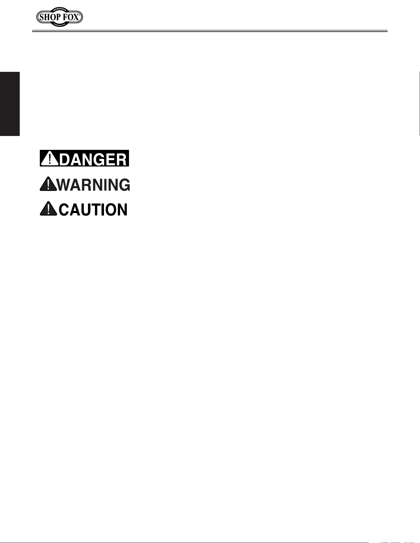
:fekifcj=\Xkli\j
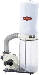
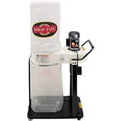
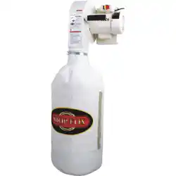
Figure (. Model W1826 identification.
Wall Mounting Bracket
Safety
Paddle
Switch
Dust Collection
Bag
I<8;Xe[le[\ijkXe[k_`j
\ek`i\dXelXcY\]fi\lj`e^
k_`jdXZ_`e\%J\i`fljg\i$
jfeXc `ealip dXp fZZli
`] jX]\kp Xe[ fg\iXk`feXc
`e]fidXk`fe `j efk le[\i$
jkff[ Xe[ ]fccfn\[% ;F
EFK i`jb pfli jX]\kp Yp
efki\X[`e^
-6-
Df[\cN(/)-=fiDXZ_`e\jD]^%J`eZ\+&()
J8=<KP
@e[`ZXk\jXgfk\ek`Xccp_XqXi[fljj`klXk`fen_`Z_#`]efkXmf`[\[#
D8Pi\jlck`ed`efifidf[\iXk\`ealip%
@e[`ZXk\jXe`dd`e\ekcp_XqXi[fljj`klXk`fen_`Z_#`]efkXmf`[\[#
N@CCi\jlck`e[\Xk_fij\i`flj`ealip%
@e[`ZXk\jXgfk\ek`Xccp_XqXi[fljj`klXk`fen_`Z_#`]efkXmf`[\[#
:FLC;i\jlck`e[\Xk_fij\i`flj`ealip%
K_`jjpdYfc`jlj\[kfXc\ikk_\lj\ikflj\]lc`e]fidXk`feXYflk
gifg\ifg\iXk`fef]k_\\hl`gd\ek#Xe[&fiXj`klXk`fek_XkdXp
ZXlj\[XdX^\kfk_\dXZ_`e\ip%
EFK@:<
J8=<KP
FNE<IËJD8EL8C% Read and understand this
owner’s manual BEFORE using machine.
Untrained users can be seriously hurt.
<P<GIFK<:K@FE% Always wear ANSI-approved
safety glasses or a face shield when operating
or observing machinery to reduce the risk of
eye injury or blindness from flying particles.
Everyday eyeglasses are not approved safety
glasses.
?8Q8I;FLJ;LJK% Dust created while using
machinery may cause cancer, birth defects,
or long-term respiratory damage. Be aware
of dust hazards associated with workpiece
materials, and always wear a NIOSH-approved
respirator to reduce your risk.
N<8I@E>GIFG<I8GG8I<C% Do not wear
clothing, apparel, or jewelry that can become
entangled in moving parts. Always tie back
or cover long hair. Wear non-slip footwear to
avoid accidental slips which could cause a loss
of work
p
iece control.
?<8I@E>GIFK<:K@FE% Always wear hearing
protection when operating or observing
loud machinery. Extended exposure to this
noise without hearing protection can cause
permanent hearing loss.
D<EK8C8C<IKE<JJ% Be mentally alert when
running machinery. Never operate under the
influence of drugs or alcohol, when tired, or
when distracted.
;@J:FEE<:K@E>GFN<IJLGGCP% Always
disconnect machine from power supply before
servicing, adjusting, or changing cutting tools
(bits, blades, cutters, etc.). Make sure switch
is in OFF position before reconnecting to avoid
an unexpected or unintentional start.
;8E><IFLJ<EM@IFED<EKJ% Do not use
machinery in wet or rainy locations, cluttered
areas, around flammables, or in poorly-lit
areas. Keep work area clean, dry, and well-
lighted to minimize risk of injury.
JkXe[Xi[DXZ_`e\ipJX]\kp@ejkilZk`fej
For Your Own Safety,
Read Manual Before Operating Machine
K_\ gligfj\ f] jX]\kp jpdYfcj `j kf XkkiXZk pfli Xkk\ek`fe kf gfjj`Yc\ _XqXi[flj Zfe[`k`fej% K_`j
dXelXclj\jXj\i`\jf]jpdYfcjXe[j`^eXcnfi[j`ek\e[\[kfZfem\pk_\c\m\cf]`dgfikXeZ\f]k_\
jX]\kpd\jjX^\j%K_\gif^i\jj`fef]jpdYfcj`j[\jZi`Y\[Y\cfn%I\d\dY\ik_XkjX]\kpd\jjX^\jYp
k_\dj\cm\j[fefk\c`d`eXk\[Xe^\iXe[Xi\efkXjlYjk`klk\]fi gifg\i XZZ`[\ek gi\m\ek`fed\X$
jli\jÇk_`ji\jgfej`Y`c`kp`jlck`dXk\cplgkfk_\fg\iXkfi
J8=<KP
JkXe[Xi[DXZ_`e\ipJX]\kp@ejkilZk`fej

-7-
Df[\cN(/)-=fiDXZ_`e\jD]^%J`eZ\+&()
J8=<KP
8GGIFM<;FG<I8K@FE% Untrained operators
can be seriously hurt by machinery. Only
allow trained or properly supervised people
to use machine. When machine is not being
used, disconnect power, remove switch keys,
or lock-out machine to prevent unauthorized
use—especially around children. Make
workshop kid proof!
FECPLJ<8J@EK<E;<;% Only use machine for
its intended purpose. Never modify or alter
machine for a purpose not intended by the
manufacturer or serious injury may result!
LJ<I<:FDD<E;<;8::<JJFI@<J% Consult
this owner’s manual or the manufacturer for
recommended accessories. Using improper
accessories will increase the risk of serious
injury.
:?@C;I<E9PJK8E;<IJ% Keep children and
bystanders a safe distance away from work
area. Stop using machine if children or
bystanders become a distraction.
I<DFM<8;ALJK@E>KFFCJ% Never leave
adjustment tools, chuck keys, wrenches, etc.
in or on machine—especially near moving
parts. Verify removal before starting!
J<:LI@E>NFIBG@<:<% When required, use
clamps or vises to secure workpiece. A secured
workpiece protects hands and frees both of
them to operate the machine.
=<<;;@I<:K@FE% Unless otherwise noted, feed
work against the rotation of blades or cutters.
Feeding in the same direction of rotation may
pull your hand into the cut.
>L8I;J:FM<IJ% Guards and covers can
protect you from accidental contact with
moving parts or flying debris. Make sure
they are properly installed, undamaged, and
working correctly before using machine.
E<M<IJK8E;FED8:?@E<% Serious injury or
accidental contact with cutting tool may
occur if machine is tipped. Machine may be
damaged.
JK89C<D8:?@E<% Unexpected movement during
operations greatly increases the risk of injury
and loss of control. Verify machines are
stable/secure and mobile bases (if used) are
locked before starting.
=FI:@E>D8:?@E<IP% Do not force machine. It
will do the job safer and better at the rate for
which it was designed.
8NBN8I;GFJ@K@FEJ% Keep proper footing and
balance at all times when operating machine.
Do not overreach! Avoid awkward hand
positions that make workpiece control difficult
or increase the risk of accidental injury.
LE8KK<E;<;FG<I8K@FE% Never leave machine
running while unattended. Turn machine off
and ensure all moving parts completely stop
before walking away.
D8@EK8@EN@K?:8I<% Follow all maintenance
instructions and lubrication schedules to
keep machine in good working condition. An
improperly maintained machine may increase
the risk of serious injury.
:?<:B;8D8><;G8IKJ% Regularly inspect
machine for damaged parts, loose bolts,
mis-adjusted or mis-aligned parts, binding,
or any other conditions that may affect safe
operation. Always repair or replace damaged
parts, wires, cords, or plugs before operating
machine.
D8@EK8@EGFN<I:FI;J%When disconnecting
cord-connected machines from power, grab
and pull the plug—NOT the cord. Pulling the
cord may damage the wires inside. Do not
handle the cord/plug with wet hands. Avoid
cord damage by keeping it away from heated
surfaces, high traffic areas, harsh chemicals,
and wet or damp locations.
<OG<I@<E:@E>;@==@:LCK@<J% If at any time you
are experiencing difficulties performing the
intended operation, stop using the machine!
Contact our Technical Support for help at
(360) 734-3482.
-8-
Df[\cN(/)-=fiDXZ_`e\jD]^%J`eZ\+&()
J8=<KP
8[[`k`feXcJX]\kp]fiDust Collectors
I<8;Xe[le[\ijkXe[k_`j
\ek`i\dXelXcY\]fi\lj`e^
k_`jdXZ_`e\%J\i`fljg\i$
jfeXc `ealip dXp fZZli
`] jX]\kp Xe[ fg\iXk`feXc
`e]fidXk`fe `j efk le[\i$
jkff[ Xe[ ]fccfn\[% ;F
EFK i`jb pfli jX]\kp Yp
efki\X[`e^
LJ<k_`jXe[fk_\idXZ_`e\ipn`k_ZXlk`fe
Xe[ i\jg\Zk% 8cnXpj Zfej`[\i jX]\kp ]`ijk#
Xj `k Xggc`\j kf pfli `e[`m`[lXc nfib`e^
Zfe[`k`fej%Efc`jkf]jX]\kp^l`[\c`e\jZXe
Y\ Zfdgc\k\Ç\m\ip j_fg \em`ifed\ek `j
[`]]\i\ek%=X`cli\kf]fccfn^l`[\c`e\jZflc[
i\jlck `e j\i`flj g\ijfeXc `ealip# [XdX^\
kf\hl`gd\ekfigffinfibi\jlckj%
MACHINE USE. This dust collector is designed for collecting wood dust and chips from woodworking
machines. DO NOT use it to collect metal, dirt, drywall, asbestos, lead paint, silica, liquids, aerosols,
biohazards, or explosive materials. Collecting the wrong materials can result in serious inhalation
hazards, fire, or machine damage.
WEAR RESPIRATOR. This machine may blow fine dust particles into the air during operation causing a
hazard to the lungs. Always wear an approved respirator during machine operation and for a short
time after.
SUSPENDED DUST PARTICLES AND IGNITION SOURCES. Do not operate the dust collector in areas where
explosion risks are high, such as near pilot lights or open flames.
EMPTYING DUST. When emptying dust from the collection bags or drum, wear a respirator and safety
glasses. Empty dust away from ignition sources and into an approved container, then dispose of
properly.
SAFE SERVICING. Disconnect the machine from power and allow the impeller to come to a complete
stop before servicing, maintenance, or adjustments.
AVOIDING FIRES. Do not allow steel particles to strike the impeller—this may produce a spark.
Sparks can smolder in the wood dust for a long time before the fire or flame is detected. If you
accidentally collect metal during operation, immediately turn off the dust collector, disconnect it
from power, and wait for all moving parts to stop. Remove the collection bags and empty the dust
into an approved air tight metal container. Prevent any chance of accidentally collecting metal
again before resuming operations.
KEEPING FINGERS SAFE. Do not allow hands, tools, hair or clothing near the open inlet during opera-
tion. The powerful suction could easily cause accidental contact with the impeller which will cause
serious personal injury or damage to the machine.
DUST HAZARD. Be aware that certain woods may cause an allergic reaction in people and animals,
especially when exposed to fine dust. Make sure you know what type of wood dust you will be
exposed to in case there is a possibility of an allergic reaction.
OPERATIONAL QUESTIONS. If, at any time, you are experiencing difficulties performing the intended
operation, stop using the machine! Then contact our Tech Support or ask a qualified expert how the
operation should be performed.
-9-
Df[\cN(/)-=fiDXZ_`e\jD]^%J`eZ\+&()
<C<:KI@:8C
<C<:KI@:8C
:`iZl`kI\hl`i\d\ekj
This machine must be connected to the correct size and
type of power supply circuit, or fire or electrical damage
may occur. Read through this section to determine if an
adequate power supply circuit is available. If a correct
circuit is not available, a qualified electrician MUST install
one before you can connect the machine to power.
A power supply circuit includes all electrical equipment
between the breaker box or fuse panel in the building
and the machine. The power supply circuit used for
this machine must be sized to safely handle the full-
load current drawn from the machine for an extended
period of time. (If this machine is connected to a circuit
protected by fuses, use a time delay fuse marked D.
)
:`iZl`kI\hl`i\d\ekj]fi)+'M
Nominal Voltage......................................... .........240V
Cycle ................................................................60 Hz
Phase .....................................................Single-Phase
Circuit Rating .................................................15 Amps
Plug/Receptacle .........................................NEMA 6-15
=lcc$CfX[:lii\ekIXk`e^
The full-load current rating is the amperage a machine
draws at 100% of the rated output power. On machines
with multiple motors, this is the amperage drawn by the
largest motor or sum of all motors and electrical devices
that might operate at one time during normal operations.
Full-Load Current Rating at 120V.......................7 Amps
Full-Load Current Rating at 240V................... 3.5 Amps
This machine is prewired to operate on a 120V power sup-
ply circuit that has a verified ground and meets the fol-
lowing requirements:
K_\ dXZ_`e\ dljk Y\ gifg\icp j\k lg
Y\]fi\ `k `j jX]\ kf fg\iXk\% ;F EFK
Zfee\Zk k_`j dXZ_`e\ kf k_\ gfn\i
jfliZ\ lek`c `ejkilZk\[ kf [f cXk\i `e
k_`jdXelXc%
@eZfii\Zkcp n`i`e^ fi ^ifle[`e^ k_`j
dXZ_`e\ZXeZXlj\\c\ZkifZlk`fe#]`i\#
fidXZ_`e\[XdX^\%Kfi\[lZ\k_`ji`jb#
fecpXe\c\Zki`Z`XefihlXc`]`\[j\im`Z\
g\ijfee\c j_flc[ [f Xep i\hl`i\[
\c\Zki`ZXcnfibfek_`jdXZ_`e\%
EFK@:<
K_\ Z`iZl`ki\hl`i\d\ekjc`jk\[ `e k_`j
dXelXc Xggcp kf X [\[`ZXk\[ Z`iZl`kÇ
n_\i\fecpfe\dXZ_`e\n`ccY\ilee`e^
XkXk`d\%@]k_`jdXZ_`e\n`ccY\
Zfee\Zk\[ kf X j_Xi\[ Z`iZl`k n_\i\
dlck`gc\ dXZ_`e\j n`cc Y\ ilee`e^ Xk
k_\jXd\k`d\#ZfejlckXhlXc`]`\[
\c\Zki`Z`Xekf\ejli\k_Xkk_\Z`iZl`k`j
gifg\icpj`q\[]fijX]\fg\iXk`fe%
Nominal Voltage ..................................................120V
Cycle ................................................................60 Hz
Phase .....................................................Single-Phase
Circuit Rating .................................................15 Amps
Plug/Receptacle.......................................... NEMA 5-15
:`iZl`kI\hl`i\d\ekj]fi()'M
This machine can be converted to operate on a 240V
power supply (details about voltage conversion can be
found later in this manual). The 240V power supply circuit
must have a verified ground and meet the requirements
that follow:
-10-
Df[\cN(/)-=fiDXZ_`e\jD]^%J`eZ\+&()
<C<:KI@:8C
>ifle[`e^I\hl`i\d\ekj
<ok\ej`fe:fi[j
This machine MUST be grounded. In the event of certain
types of malfunctions or breakdowns, grounding provides
a path of least resistance for electric current to travel—in
order to reduce the risk of electric shock.
Improper connection of the equipment-grounding wire will
increase the risk of electric shock. The wire with green
insulation (with/without yellow stripes) is the equipment-
grounding wire. If repair or replacement of the power
cord or plug is necessary, do not connect the equipment-
grounding wire to a live (current carrying) terminal.
Check with a qualified electrician or service personnel
if you do not understand these grounding requirements,
or if you are in doubt about whether the tool is
properly grounded. If you ever notice that a cord or
plug is damaged or worn, disconnect it from power, and
immediately replace it with a new one.
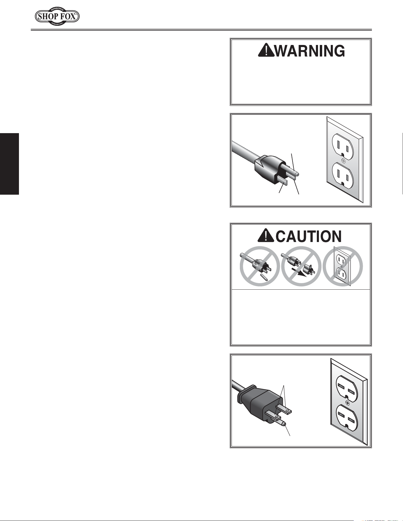
Grounding Prong
Current Carrying Prongs
6-15 PLUG
GROUNDED
6-15 RECEPTACLE
220V
=`^li\*% NEMA 6-15 plug & receptacle.
=fi()'M:fee\Zk`feGi\n`i\[
=fi)+'M:fee\Zk`feDljkY\I\n`i\[
We do not recommend using an extension cord with this
machine. Extension cords cause voltage drop, which may
damage electrical components and shorten motor life.
Voltage drop increases with longer extension cords and
the gauge smaller gauge sizes (higher gauge numbers
indicate smaller sizes).
Any extension cord used with this machine must contain a
ground wire, match the required plug and receptacle, and
meet the following requirements:
K_\ dXZ_`e\ dljk Y\ gifg\icp j\k lg
Y\]fi\ `k `j jX]\ kf fg\iXk\% ;F EFK
Zfee\Zk k_`j dXZ_`e\ kf k_\ gfn\i
jfliZ\ lek`c `ejkilZk\[ kf [f cXk\i `e
k_`jdXelXc%
;F EFK df[`]p k_\ gifm`[\[ gcl^ fi
lj\XeX[Xgk\i`]k_\gcl^n`ccefk
]`k k_\ i\Z\gkXZc\% @ejk\X[# _Xm\ Xe
\c\Zki`Z`Xe`ejkXcck_\gifg\ii\Z\gkXZc\
fe X gfn\i jlggcp Z`iZl`k k_Xk d\\kj
k_\i\hl`i\d\ekj]fik_`jdXZ_`e\%
Minimum Gauge Size (120V)...................................14 AWG
Minimum Gauge Size (240V)...................................16 AWG
Maximum Length (Shorter is Better).........................50 ft.
A NEMA 6-15 plug has a grounding prong that must be
attached to the equipment-grounding wire inside the
included power cord. The plug must only be inserted
into a matching receptacle (see Figure) that is properly
installed and grounded in accordance with all local codes
and ordinances.
This machine is equipped with a power cord that has
an equipment-grounding wire and NEMA 5-15 grounding
plug. The plug must only be inserted into a matching
receptacle (see Figure) that is properly installed and
grounded in accordance with local codes and ordinances.
Grounding Prong
Neutral Hot
5-15 PLUG
GROUNDED
5-15 RECEPTACLE
110V
=`^li\)% NEMA 5-15 plug & receptacle.
120V
240V
-11-
Df[\cN(/)-=fiDXZ_`e\jD]^%J`eZ\+&()
<C<:KI@:8C
Voltage Conversion to 240V
The voltage conversion MUST be performed by an
electrician or qualified service personnel. To perform the
voltage conversion, rewire the motor to the new voltage
and install the correct plug, according to the provided
wiring diagram.
Note: If the diagram included on the motor conflicts with
the one on GX^\),in this manual, the motor may have
changed since the manual was printed. Use the diagram
provided inside the motor wiring junction box.
Items Needed Qty
E]^aa^eh=ZVYHXgZlYg^kZg'#####################################&
:aZXig^XVaIVeZ############################################6hCZZYZY
L^gZCji&)6L<m(###############################################&
+"&*Eaj\####################################################################&
To convert the Model W1826 to 240V, do these steps:
1. DISCONNECT MACHINE FROM POWER!
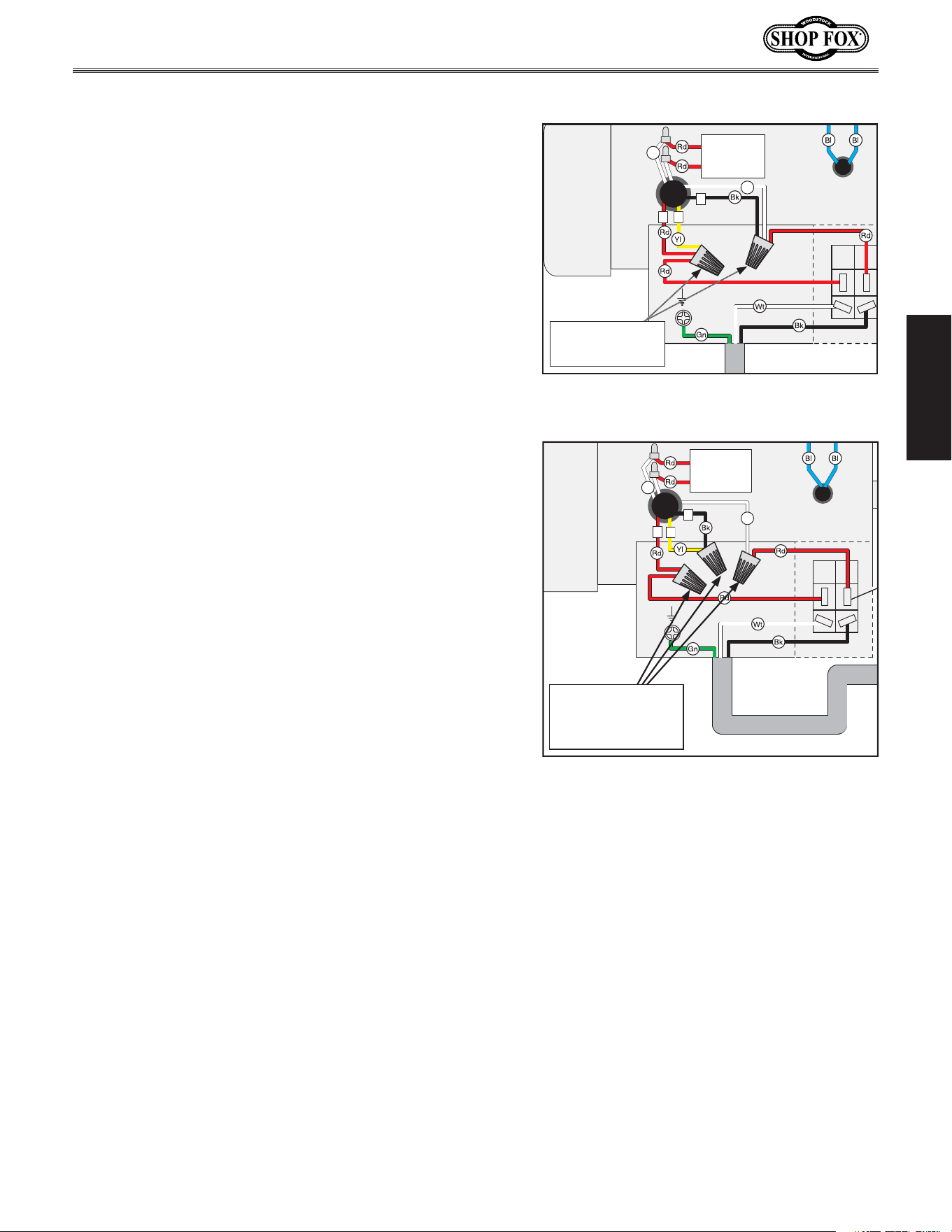
2. Open the motor junction box, then loosen the wire
nuts indicated in Figure +%
3. Use wire nuts to connect the wires as indicated
in Figure ,. Twist all three wire nuts onto their
respective wires and wrap them with electrical tape
so they will not come loose.
4. Close and secure the motor junction box.
5. Remove the 5-15 plug from the power cord and
install a 6-15 plug according to the manufacturer's
instructions.
Figure +. Location of wire nuts to be
loosened when converting voltage.
Figure ,. Model W1826 rewired to 240V.
Ground
Li
(
&
'
Run
Capacitor
30MFD
250VAC
Li
Connect
Wires with Nuts
Here
Ground
Li
Run
Capacitor
30MFD
250VAC
'
(
&
Li
Loosen these
wire nuts
-12-
Df[\cN(/)-=fiDXZ_`e\jD]^%J`eZ\+&()
J<KLG
B\\g dXZ_`e\ [`jZfee\Zk\[ ]ifd
gfn\ilek`c`ejkilZk\[fk_\in`j\%
This machine has been carefully packaged for safe
transportation. If you notice the machine has been
damaged during shipping, please contact your authorized
Shop Fox dealer immediately.
LegXZb`e^
J<KLG
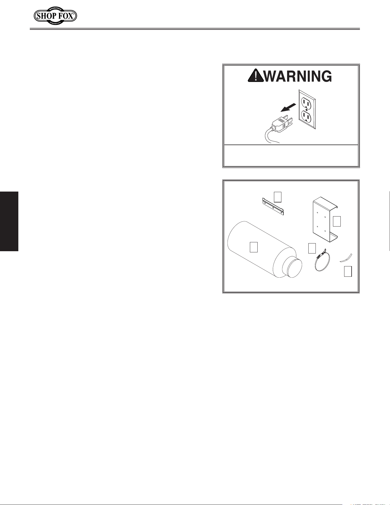
The following is a description of the main components
shipped with the Model W1826. Lay the components out
to inventory them.
Note: If you can't find an item on this list, check the
mounting location on the machine or examine the
packaging materials carefully. Occasionally we pre-install
certain components for safer shipping.
Inventory Qty
A. Collector Body and
Fan/Motor Assembly (Not Shown) .........................1
B. Wall Mounting Bracket ......................................1
C. Motor Bracket ................................................1
D. Dust Collection Bag..........................................1
E. Bag Clamp ....................................................1
F. Adhesive Foam Strip 4 x 20 x 430mm .....................1
Hardware (Not Shown)
• Flange Bolts
1
⁄4"-20 x
1
⁄2" (Fan Motor) ..................4
• Open End Wrench 10 x 12mm ............................1
@em\ekfip
If any nonproprietary parts are missing (e.g. a nut or a
washer), we will gladly replace them; or for the sake of
expediency, replacements can be obtained at your local
hardware store.
B
C
F
E
D
=`^li\-% Machine Inventory.
-13-
Df[\cN(/)-=fiDXZ_`e\jD]^%J`eZ\+&()
J<KLG
D8B<pflij_fgÈZ_`c[jX]\%É
<ejli\k_XkpflinfibgcXZ\
`j`eXZZ\jj`Yc\kfZ_`c[i\eYp
Zcfj`e^Xe[cfZb`e^Xcc\ekiXeZ$
\jn_\epflXi\XnXp%E<M<I
Xccfn lekiX`e\[ m`j`kfij `e
pfli j_fg n_\e Xjj\dYc`e^#
X[aljk`e^fi fg\iXk`e^\hl`g$
d\ek%
DXZ_`e\GcXZ\d\ek
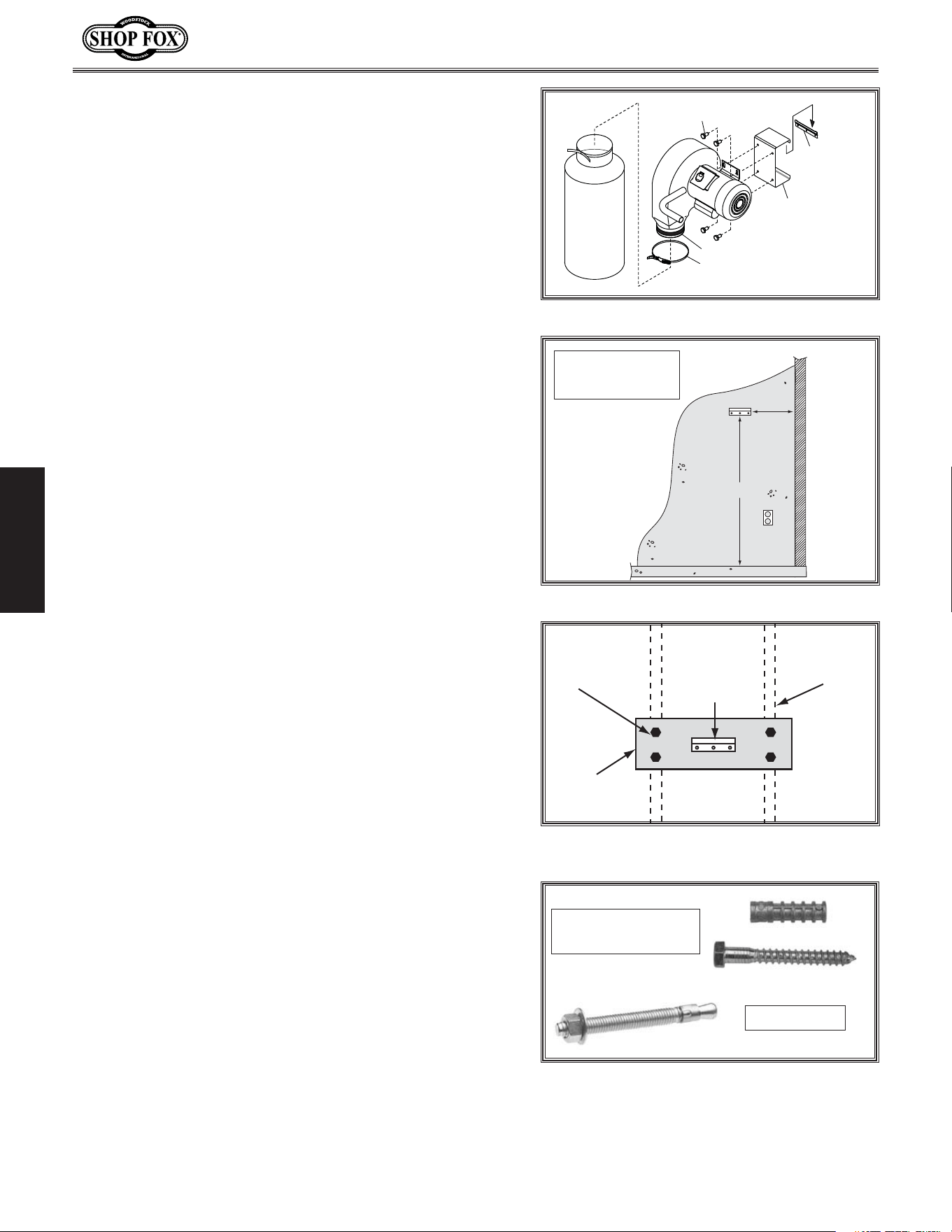
Figure .. Wall mounting bracket positioning.
Wall
Wall
Floor
23"
Minimum
Front View
Wall
Power
Floor
Wall
Keep
Area
Clear
Side View
Minimum
Motor
Cooling
Air Gap
3"
45"
Minimum
Weight Load: Refer to the Machine Data Sheet
for the weight of your machine. Make sure that
the surface upon which the machine is placed
will bear the weight of the machine and the dust
collection bag when full. Additionally, consider
the weight of any dynamic loading that may occur
when operating the machine.
Space Allocation: Provide enough space around
the machine for adequate motor ventilation and
the removal/ installation of the collection bag.
See below for required space allocation.
Lighting: Lighting around the machine must be
adequate enough that operations can be per-
formed safely. Shadows, glare, or strobe effects
that may distract or impede the operator must
be eliminated.
Physical Environment: The physical environment
where the machine is operated is important for
safe operation and longevity of machine compo-
nents. For best results, operate this machine in a
dry environment that is free from excessive mois-
ture, hazardous chemicals, airborne abrasives, or
extreme conditions. Extreme conditions for this
type of machinery are generally those where the
ambient temperature range exceeds 41°–104°F;
the relative humidity range exceeds 20–95% (non-
condensing); or the environment is subject to
vibration, shocks, or bumps.
Electrical Installation: Place this machine near
an existing power source. Make sure all power
cords are protected from traffic, material han-
dling, moisture, chemicals, or other hazards.
Make sure to leave access to a means of discon-
necting the power source or engaging a lockout/
tagout device, if required.
-14-
Df[\cN(/)-=fiDXZ_`e\jD]^%J`eZ\+&()
J<KLG
8jj\dYcp
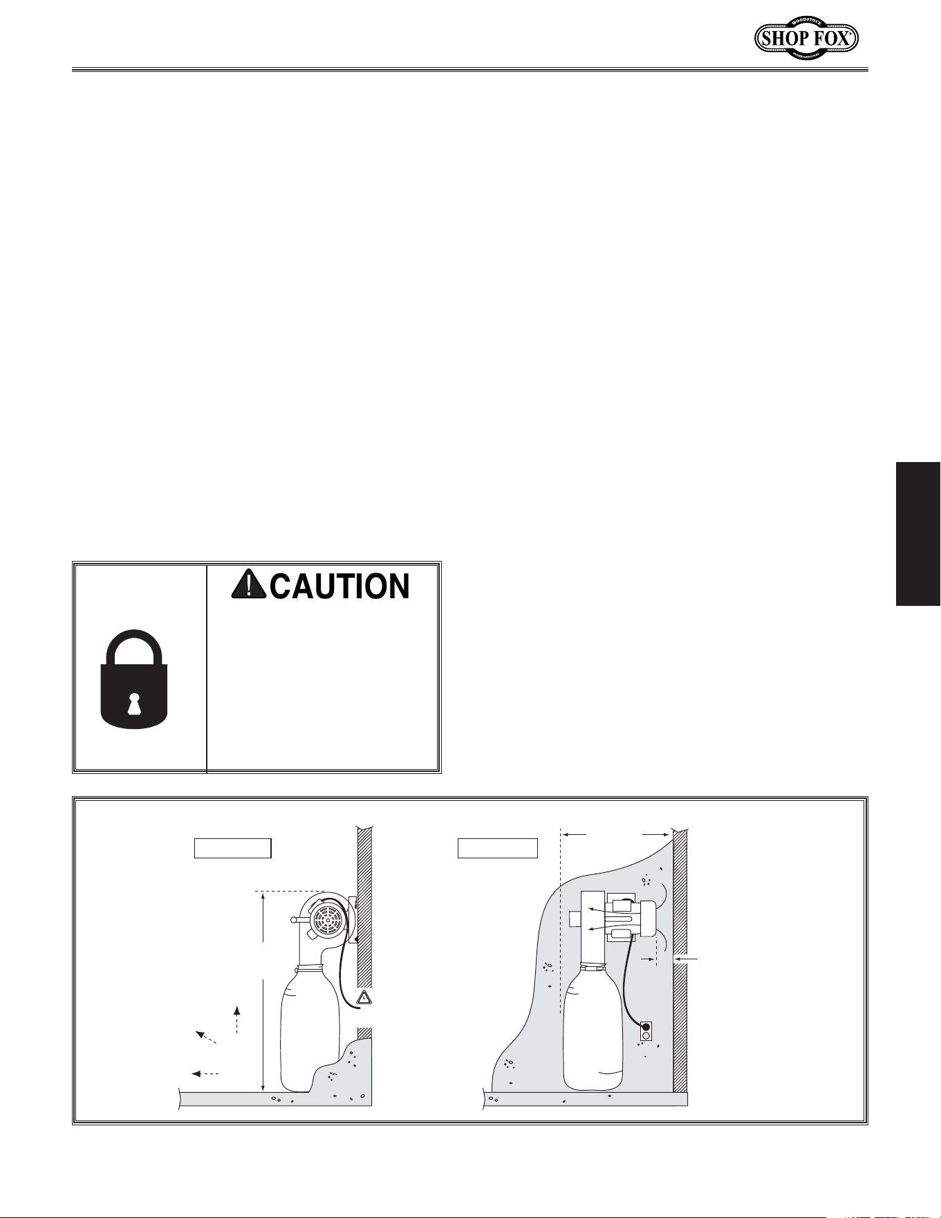
Wall
Motor
Flange Bolt
Adhesive Foam Strip
Quick Release Clamp
Mounting
Bracket
Bracket
Figure /. Dust collector assembly diagram.
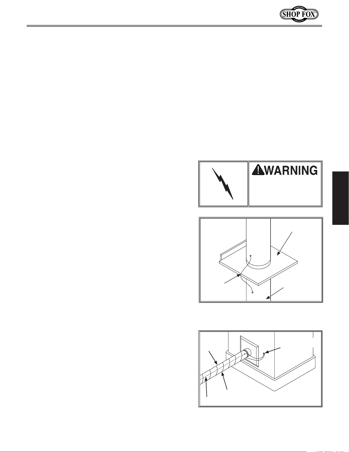
Wall
Wall
Floor
42"
4.5"
Minimum
Figure 0. Dust collector mounting.
Figure ((. Typical fasteners for mounting
dust collector bracket to masonry or
concrete walls.
Anchor Stud
Lag Shield Anchor
and Lag Screw
LVaaHijY
Hjeedgi
7dVgY
LVaa
Bdjci^c\
7gVX`Zi
AV\7dai
Figure ('. Mounting bracket secured to
support board on wall studs.
Note: Drawing
not to scale.
For adequate motor cooling, the motor fan intake must not
be restricted by a wall or cabinet.
To assemble and mount the dust collector:
1. Fasten the motor bracket to the motor base with the
four included flange bolts, and install the adhesive
foam strip on the dust collector outlet port at the
location shown in Figure 8.
2. Using the wall mounting bracket as a template, mark
the mounting hole location so the bottom of the
mounting bracket is a miniumum of 42" from the floor
and at least 4
1
⁄2" away from any wall, as shown in
Figure 9.
— If mounting to a wood framed wall (with or without
drywall), the bracket must be mounted directly to
a support board that is wide enough to span and
mount onto two wall studs. Mount the support to
the wall studs with lag screws, then mount the
bracket to the support with appropriate fasteners,
as shown in Figure 10.
— If mounting to a concrete or masonry wall, attach
the bracket using lag shield anchors with lag screws
or anchor studs (see Figure 11).
3. After the mounting bracket is installed on the wall,
have another person help you hang the dust collector
on the bracket.
4. Install the dust collection bag with the bag clamp
(see Figure 8), then connect the ducting. Refer to
Collection System on the next page for grounding
requirements.
-15-
Df[\cN(/)-=fiDXZ_`e\jD]^%J`eZ\+&()
J<KLG
Collection System
Always guard against
static electrical build
up by grounding all dust
collection lines.
Plastic flex-hose is an insulator, and dust particles moving
against the walls of the hose creates a static electrical
build up. This charge will build until it discharges to a
ground. If a grounding medium is not available to prevent
static electrical build up, the electrical charge will arc
to the nearest grounded source. This electrical discharge
may cause an explosion and subsequent fire inside the
system.
To protect against static electrical build up inside a non-
conducting duct, a bare copper wire should be placed
inside the duct along its length and grounded to the dust
collector. You must also confirm that the dust collector is
continuously grounded through the electrical circuit to the
electric service panel.
Be sure that you extend the bare copper wire down all
branches of the system. Do not forget to connect the wires
to each other with wire nuts when two branches meet at
a “Y” or “T” connection.
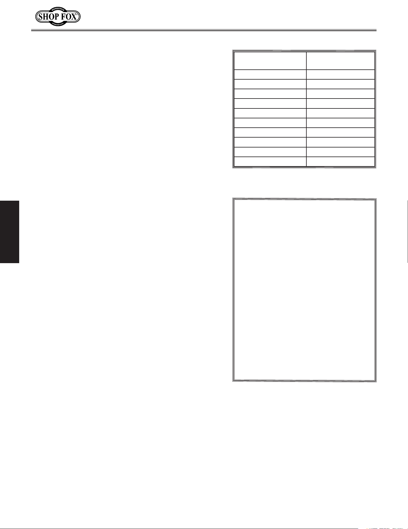
Ensure that the entire system is grounded. If using plastic
blast gates to direct air flow, the grounding wire must be
jumped (see Figure ()) around the blast gate without
interruption to the grounding system.
Figure (*. Flex-hose grounded to machine.
Ground Screw
Flex
Hose
Internal Ground Wire
External Ground Wire
We also recommend wrapping the outside
of all plastic ducts with bare copper wire
to ground the outside of the system against
static electrical build up. Wire connections
at Y’s and T’s should be made with wire
nuts.
Attach the bare ground wire to each sta-
tionary woodworking machine and attach
the dust collector frame with a ground
screw, as shown in Figure (*. Ensure that
each machine is continuously grounded to
the grounding terminal in your electric ser-
vice panel.
You have many choices regarding dust collection ducting,
but flexible hose is the most common for this size of
machine. However, be aware that there is a fire or
explosion hazard if plastic duct material is used for dust
collection without being grounded against static electrical
charge build-up.
Flexible rubber hose, polyethylene, plastic flex-hose and
other flexible ribbed hose is generally used for short runs.
There are many different types of flex hose on the market
today. These are manufactured from materials such as
polyethylene, PVC, cloth hose dipped in rubber and even
metal, including steel and aluminum.
If using flex-hose, you should choose one of the many
types that are designed specifically for the movement of
solid particles, i.e. dust, grains and plastics. However, the
cost of specifically designed flexible duct can vary greatly.
Shop Fox offers polyethylene and steel flex hose.
Figure (). Ground jumper wire when using
plastic blast gates or elbows and metal
duct.
Plastic Blast Gate
Copper
Ground Wire
Metal Duct
Material Selection
;lZk>ifle[`e^
-16-
Df[\cN(/)-=fiDXZ_`e\jD]^%J`eZ\+&()
J<KLG
Dust Collection
Since each machine produces a different amount of
sawdust, the requirements for the minimum amount of
CFM to move that sawdust is unique to the machine (for
example, a planer produces more sawdust than a table
saw). Knowing this required CFM is important to gauging
which size of duct to use.
Figure (+ provides a close estimation of the required CFM
based on dust port size. A machine that generates large
wood chips should be placed as close to the dust collector
as possible.
Figure (+. Approximate CFM reduction,
based on machine dust port size.
Figure (,. Typical ducting sizes and port
sizes for various machines.
Machine Average Dust Port Size
Table Saw .........................................4"
Miter/Radial-Arm Saw ...........................2"
Jointer (6" and smaller) .........................4"
Jointer (8"-12") ....................................5"
Thickness Planer (13" and smaller) ............4"
Thickness Planer (14"-20") ......................6"
Shaper .............................................4"
Router (mounted to table) ......................2"
Bandsaw ...........................................4"
Lathe ............................................... 4"
Disc Sander (12" and smaller) ..................2"
Disc Sander (13-18") ..............................4"
Belt Sander (6" and smaller) ....................2"
Belt Sander (7"-9") ...............................3"
Edge Sander (6" x 80" and smaller) ............4"
Edge Sander (6" x 80" and larger) .............5"
Drum Sander (24" and smaller) ........... 2 x 4"
Drum Sander (24" and larger) ............. 4 x 4"
Widebelt Sander (18" and smaller) ............5"
Widebelt Sander (24"-37" single head) ... 2 x 6"
Widebelt Sander (24"-51" double head) .. 5 x 4"
Machine
Dust Port Size
Approximate Required
CFM
2" 98
2.5" 150
3" 220
4" 395
5" 614
6" 884
7" 1203
8" 1570
9" 1990
10" 2456
If your machine doesn't have a built in dust port, use
Figure (, to verify which size of ducting to install on your
machine.
-17-
Df[\cN(/)-=fiDXZ_`e\jD]^%J`eZ\+&()
J<KLG
Gfn\i:fee\Zk`fe
Connecting Power
Disconnecting Power
After you have completed all previous setup instructions
and circuit requirements, the machine is ready to be
connected to the power supply.
To prevent accidental damage to the power cord, make
sure it is kept away from potential damage sources at
all times—whether connected or not. Potential damage
sources include high traffic areas, sharp objects, heat
sources, harsh chemicals, water, damp areas, etc.
To avoid unexpected startups or property damage, use
the following steps whenever connecting or disconnecting
the machine.
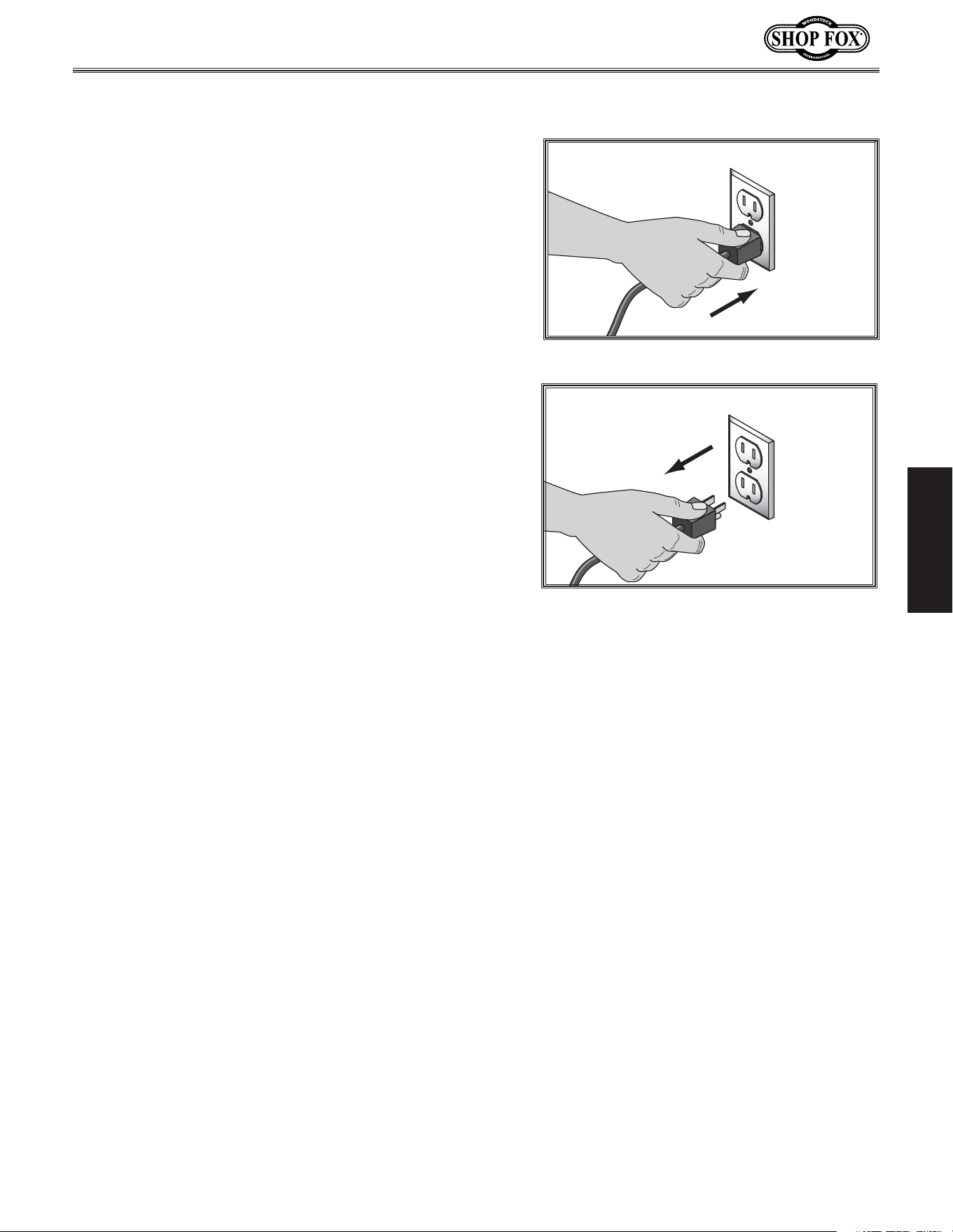
(% Turn the machine power switch F==%
)% @nsert the power cord plug into a matching
power supply receptacle. The machine is now
connected to the power source.
(% Turn the machine power switchF==%
)% Grasp the molded plug and pull it completely out of
the receptacle. Do not pull by the cord as this may
damage the wires inside.
Figure (-. Connecting power.
Figure (.. Disconnecting power.
-18-
Df[\cN(/)-=fiDXZ_`e\jD]^%J`eZ\+&()
J<KLG
Once the assembly is complete, test run your machine
to make sure it runs properly and is ready for regular
operation.
The test run consists of verifying the following: 1) The
motor powers up and runs correctly, and 2) the safety
disabling mechanism on the switch works correctly.
If, during the test run, you cannot easily locate the source
of an unusual noise or vibration, stop using the machine
immediately, then review KiflYc\j_ffk`e^ on GX^\)-.
If you still cannot remedy a problem, contact our Tech
Support at (360) 734-3482 for assistance.
Kfk\jkilek_\dXZ_`e\[fk_\j\jk\gj1
(% Make sure you understand the safety instructions
at the beginning of the manual, and verify that the
machine is setup properly.
)% Ensure all tools and objects used during setup are
cleared away from the machine.
*% Verify that the machine is operating correctly by
turning it FE.
— When operating correctly, the machine runs
smoothly with little or no vibration or rubbing
noises.
— Investigate and correct strange or unusual noises
or vibrations before operating the machine further.
Always disconnect the machine from power when
investigating or correcting potential problems.
+% Turn the machine F==.
,% Remove the switch disabling key (see =`^li\(/).
-% Try to start the machine.
— If the machine does not start, the switch disabling
feature is working as designed.
— If the machine does start, immediately disconnect
machine from power. The switch disabling feature
is not working correctly. Call Tech Support for
help.
K\jk Ile
=`^li\(/% Removing switch key from
paddle switch.
Gifa\Zk`c\j k_ifne ]ifd k_\ dXZ_`e\
Zflc[ ZXlj\ j\i`flj \p\ `ealip% N\Xi
jX]\kp ^cXjj\j kf i\[lZ\ k_\ i`jb f]
`ealip%
-19-
Df[\cN(/)-=fiDXZ_`e\jD]^%J`eZ\+&()
FG<I8K@FEJ
FG<I8K@FEJ
I<8; Xe[ le[\ijkXe[ k_`j \ek`i\ `ejkilZk`fe dXelXc
Y\]fi\ lj`e^ k_`j dXZ_`e\% J\i`flj g\ijfeXc `ealip
dXpfZZli`]jX]\kp Xe[ fg\iXk`feXc `e]fidXk`fe`jefk
le[\ijkff[ Xe[ ]fccfn\[% ;F EFK i`jb pfli jX]\kp Yp
efki\X[`e^
If you have never used this type of machine
or equipment before, WE STRONGLY REC-
OMMEND that you read books, trade maga-
zines, or get formal training before begin-
ning any projects. Regardless of the content
in this section, Woodstock will not be held
liable for accidents caused by lack of train-
ing.
>\e\iXc
DXZ_`e\JkfiX^\
Operating your Model W1826 is simple and straightfor-
ward. Position the machine near the dust collector where
it will not interfere with the workpiece being processed,
connect the ducting, connect the ducting ground, and you
are ready to begin.
Keep in mind that the dust collector is intended for single
machine use and is not designed to draw dust through long
runs and multiple ports simultaneously. We do not recom-
mend using ducting longer than 10 feet. Otherwise, dust
collection efficiency will be greatly reduced.
When the dust collector is not in use, unplug the
power cord from the power source. Place the cord away
from potential damage sources, such as high traffic areas,
sharp objects, heat sources, harsh chemicals, water, damp
areas, etc.
Damage to your eyes and lungs could
result from using this machine without
proper protective gear. Always wear
safety glasses and a respirator when
operating this machine.
Do NOT put hands or small objects
near inlet openings during operation.
Objects sucked into the inlet will hit
the impeller blade. Failure to heed
this warning could result in personal
injury or property damage.
-20-
Model W1826 (For Machines Mfg. Since 4/12)
OPERATIONS
Accessories
The following dust collector accessories may be available through your local Woodstock International
Inc. Dealer. If you do not have a dealer in your area, these products are also available through online
dealers. Please call or e-mail Woodstock International Inc. Customer Service to get a current listing of
dealers at: 1-800-840-8420 or at sales@woodstockint.com.
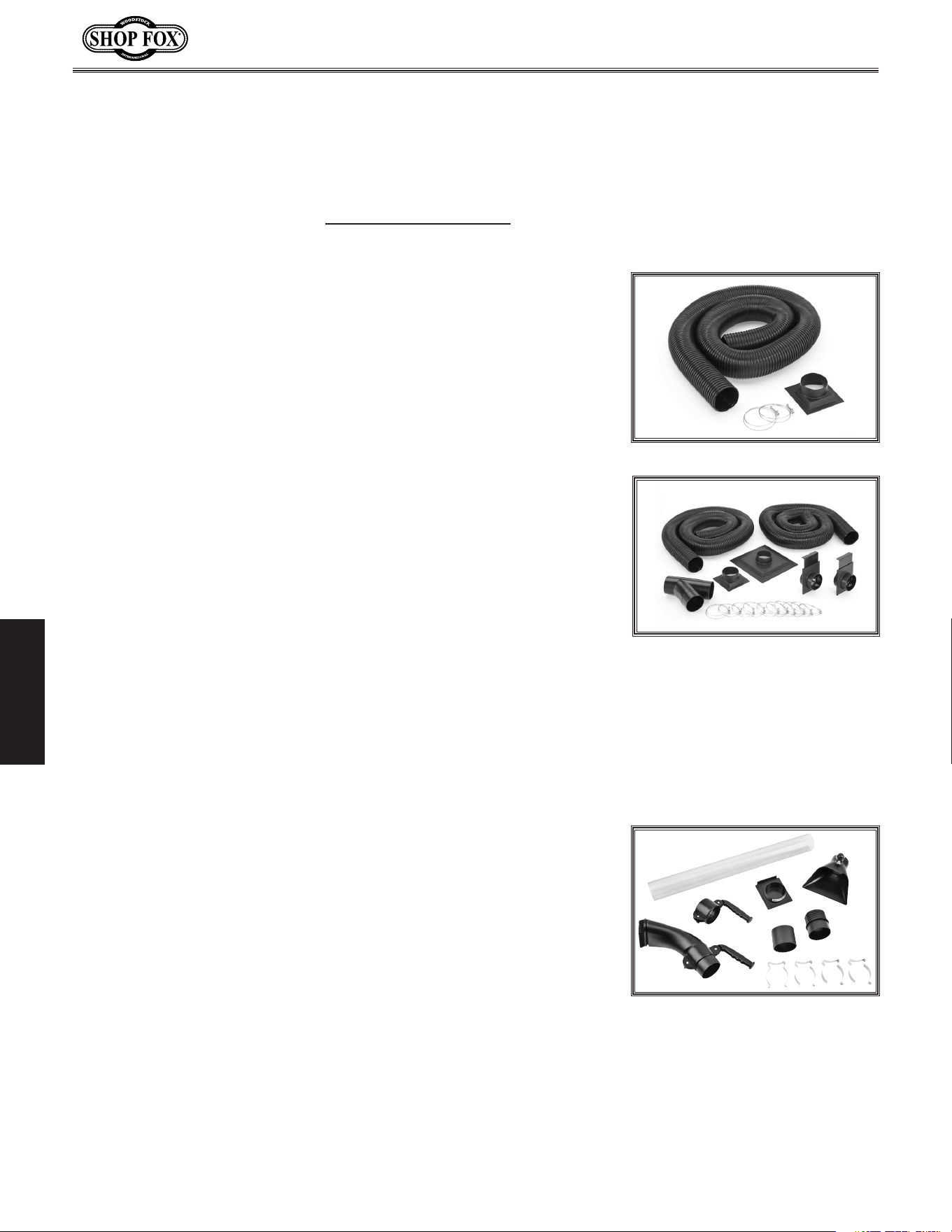
The Shop Fox W1054 Dust Collection Kit #1 contains everything
needed for a single machine hookup, including simple and concise
instructions.
Features:
(1) 4" x 10 ft. Black Plastic Hose
(1) Universal Dust Hood
(2) 4" Wire Hose Clamps
Pick up free dust in your shop with the Shop Fox D3756 Dust
Collection Accessories Kit. This kit features simple connection to
your dust collection system with versatile quick connect fittings that
make set-up easy. The fittings attach to your 4" flexible dust collec-
tion hose. 4" connection hose and hose clamp not included.
Set includes:
4" quick connect blast gate
Bench brush attachment
Floor sweep attachment with swivel caster
Quick connect coupler
Quick connect hose attachment
Two adjustable handles
Four mounting brackets
4" x 3' clear pipe
The Shop Fox W1055 Dust Collection Kit #2 takes our dust
collection kit concept a step further by providing the necessary
hoses, clamps, hoods and fittings to connect two woodworking
machines to a dust collector. Air flow to each machine is controlled
by a blast gate. Kit comes complete with comprehensive instructions
and can be expanded even further using our other dust collection
accessories (list enclosed in each box).
Features:
(2) 4" Blast Gates
(2) 4" x 10 ft. Black Plastic Hose
(1) Tablesaw Dust Hood
(1) Universal Dust Hood
(1) 4" Y-Fitting
(10) 4" Wire Hose Clamps
-21-
Model W1826 (For Machines Mfg. Since 4/12)
OPERATIONS
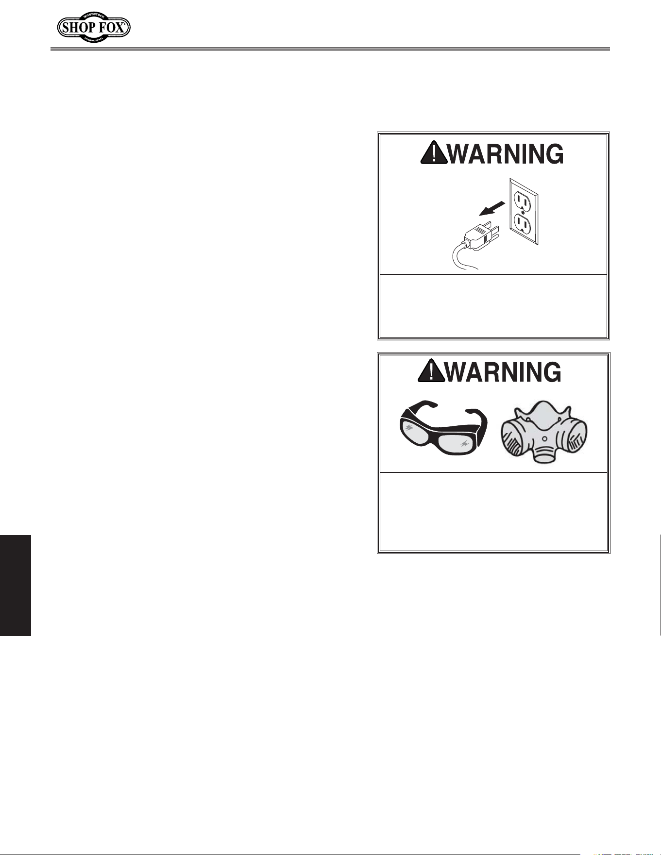
The Shop Fox W1746 is one machine that will sit in the shop and
gather dust. Fine dust that is. With its three speed fan, automatic
shut-off and 0.3 micron filter, this Fine Air Filter circulates shop air
and captures the finest dust that otherwise stays suspended. Even
with an efficient dust collector, if other machines are making dust,
you need the Fine Air Filter. Some of the typical particles that the
filter will remove are smoke, dust mites, pollen, mold spores, and
general airborne debris.
Features:
Motor: 120V, 60Hz
Filter size: 13
1
⁄4" x 14
1
⁄4" x 1
1
⁄4"
Standard filtration: 0.3 microns
Fan sound rating: 42 dB
Fan speeds: 3
Air movement: 100, 140 & 200 CFM
Automatic timed shut-off
Fan off delay: 4 settings
Approximate shipping weight: 18 lbs.
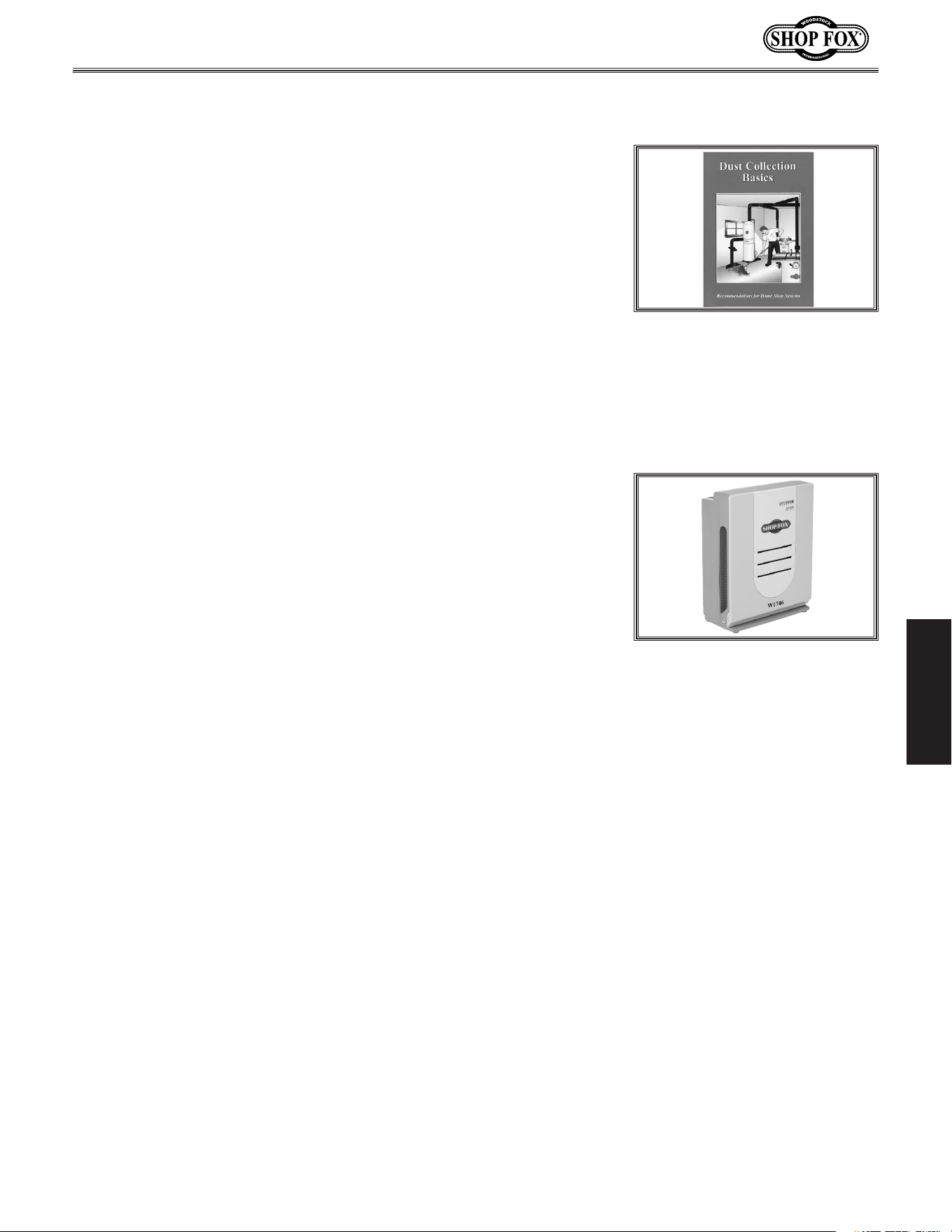
Many do-it-yourselfers trying to design and set up a central dust
collection system lack the information needed to build such a
system! This W1050 Dust Collection Basics book skillfully guides
the woodworker through all the steps necessary in the design
and construction of an efficient system and provides tips for easy
installation. With sixty pages of concise information, including
photographs and illustrations, this handbook is a "must."
Features:
Covers design and construction of an efficient system.
Provides tips for easy installation.
Concise Information
Photographs & Illustrations
-22-
Df[\cN(/)-=fiDXZ_`e\jD]^%J`eZ\+&()
D8@EK<E8E:<
Since all bearings are shielded and permanently lubri-
cated, simply leave them alone until they need to be
replaced. Do not lubricate them.
For optimum performance from your machine, follow this
maintenance schedule and refer to any specific instructions
given in this section.
Daily Check:
• Loose mounting bolts.
• Worn switch.
• Worn or damaged wires.
• Full collection bag.
• Any other unsafe condition.
D8@EK<E8E:<
JZ_\[lc\
ClYi`ZXk`fe
Always empty the collection bag on a regular basis.
Emptying the collection bag allows the machine to oper-
ate at a much higher level of efficiency. Always wear the
appropriate respirator or dust mask and safety glasses
when emptying the collection bag. Small dust particles
can escape the bag during emptying, causing them to
become airborne and easily inhaled. This microscopic
airborne dust is unsafe to breathe and can cause serious
health problems.
9X^:c\Xe`e^
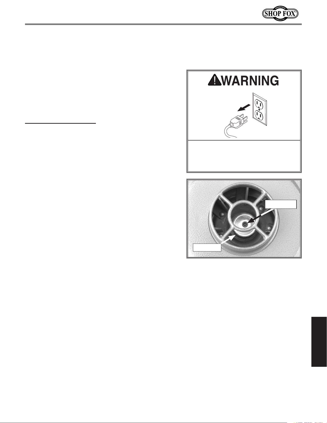
MAKE SURE that your machine is
unplugged during all maintenance pro-
cedures! If this warning is ignored, seri-
ous personal injury may occur.
Damage to your eyes and lungs could
result from using this machine without
proper protective gear. Always wear
safety glasses and a respirator when
operating this machine.
-23-
Df[\cN(/)-=fiDXZ_`e\jD]^%J`eZ\+&()
J<IM@:<
This section covers the most common service adjustments
or procedures that may need to be made during the life
of your machine.
If you require additional machine service not included
in this section, please contact Woodstock International
Technical Support at (360) 734-3482 or send e-mail to:
tech-support@shopfox.biz.
>\e\iXc
D8B< JLI< k_Xk pfli dXZ_`e\ `j
legcl^^\[ [li`e^ Xcc j\im`Z\ gifZ\$
[li\j @] k_`j nXie`e^ `j `^efi\[# j\i`$
fljg\ijfeXc`ealipdXpfZZli%
J<IM@:<
DISCONNECT DUST COLLECTOR FROM POWER BEFORE
ATTEMPTING THIS PROCEDURE!
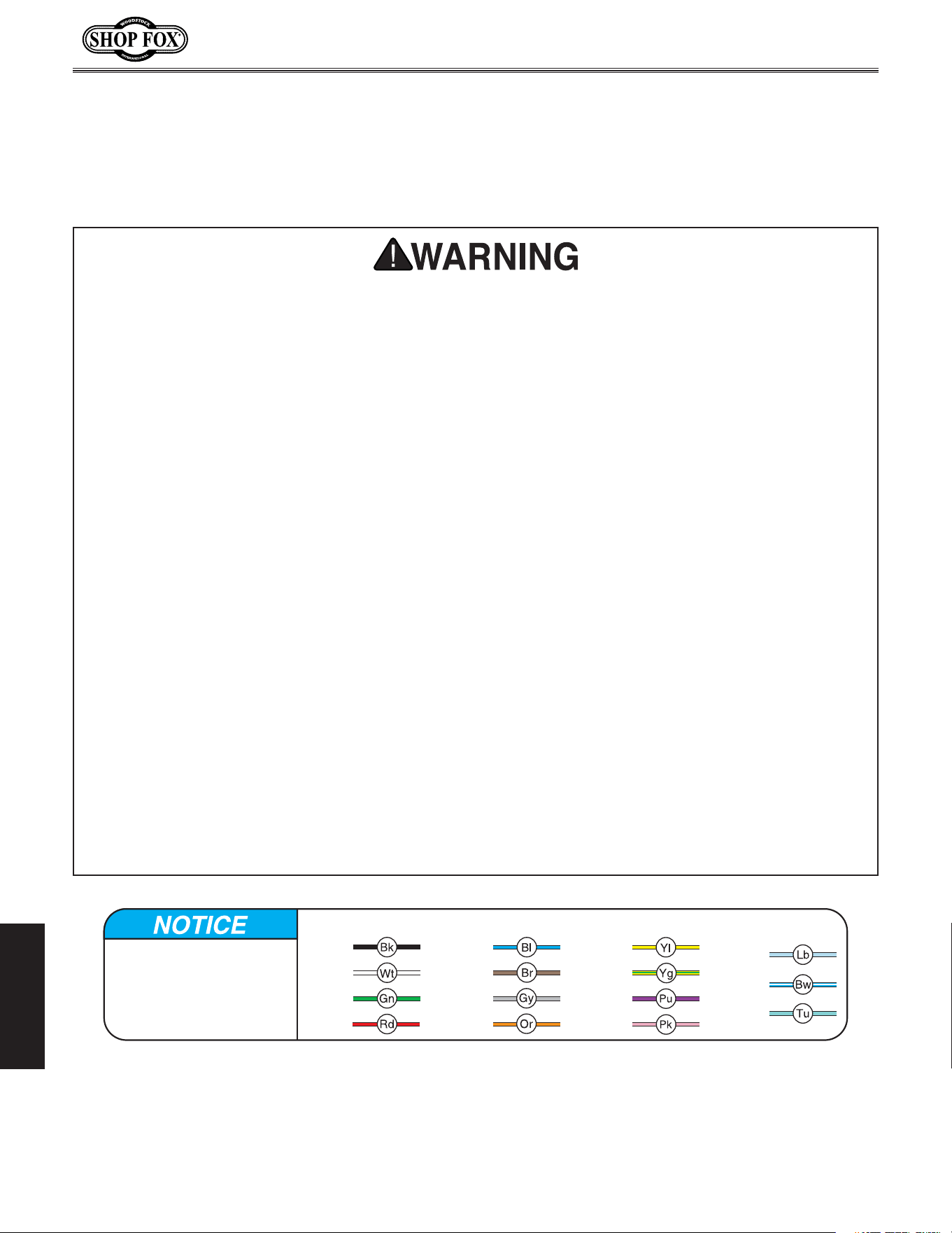
Periodically check the impeller to make sure it is tight on
the motor shaft. Any unusual vibration or noise may be
an indication the impeller has loosened. A set screw and
a left-hand cap screw secure the impeller to the shaft.
These can be accessed through the inlet cover, as shown
in Figure (0.
@dg\cc\iK`^_k\e`e^
Figure (0. Impeller screw locations.
Set Screw
Cap Screw
-24-
Df[\cN(/)-=fiDXZ_`e\jD]^%J`eZ\+&()
J<IM@:<
These pages are current at the time of printing. However, in the spirit of improvement, we may
make changes to the electrical systems of future machines. Study this diagram carefully. If you notice
differences between your machine and these wiring diagrams, call Woodstock International Technical
Support at (360) 734-3482.
(% J?F:B?8Q8I;% Working on wiring that is
connected to a power source is extremely
dangerous. Touching electrified parts will
result in personal injury including but not
limited to severe burns, electrocution,
or death. Disconnect the power from
the machine before servicing electrical
components!
)% HL8C@=@<;<C<:KI@:@8E% Due to the
inherent hazards of electricity, only a
qualified electrician should perform wiring
tasks on this machine. If you are not a
qualified electrician, get help from one
before attempting any kind of wiring job.
*% N@I<:FEE<:K@FEJ% All connections must
be tight to prevent wires from loosening
during machine operation. Double-check all
wires disconnected or connected during any
wiring task to ensure tight connections.
+% N@I<&:FDGFE<EK;8D8><% Damaged
wires or components increase the risk of
serious personal injury, fire, or machine
damage. If you notice that any wires or
components are damaged while performing
a wiring task, replace those wires or
components before completing the task.
,% DFKFIN@I@E>% The motor wiring shown
in these diagrams is current at the time
of printing, but it may not match your
machine. Always use the wiring diagram
inside the motor junction box.
-% DF;@=@:8K@FEJ% Using aftermarket parts or
modifying the wiring beyond what is shown
in the diagram may lead to unpredictable
results, including serious injury or fire.
.% :8G8:@KFIJ&@EM<IK<IJ% Some capacitors
and power inverters store an electrical
charge for up to five minutes after being
disconnected from the power source. To
avoid being shocked, wait at least this long
before working on these components.
/% <C<:KI@:8CI<HL@I<D<EKJ% You MUST
follow the electrical requirements at the
beginning of this manual when connecting
your machine to a power source.
0% <OG<I@<E:@E>;@==@:LCK@<J% If you are
experiencing difficulties understanding
the information included in this section,
contact our Technical Support at (360) 734-
3482.
<c\Zki`ZXcJX]\kp@ejkilZk`fej
The photos and diagrams
included in this section are
best viewed in color. You
can view these pages in
color at www.shopfox.biz.
BLACK
WHITE
GREEN
RED
BLUE
BROWN
GRAY
ORANGE
YELLOW
YELLOW
GREEN
PURPLE
PINK
LIGHT
BLUE
BLUE
WHITE
TUR-
QUOISE
WIRING DIAGRAM COLOR KEY
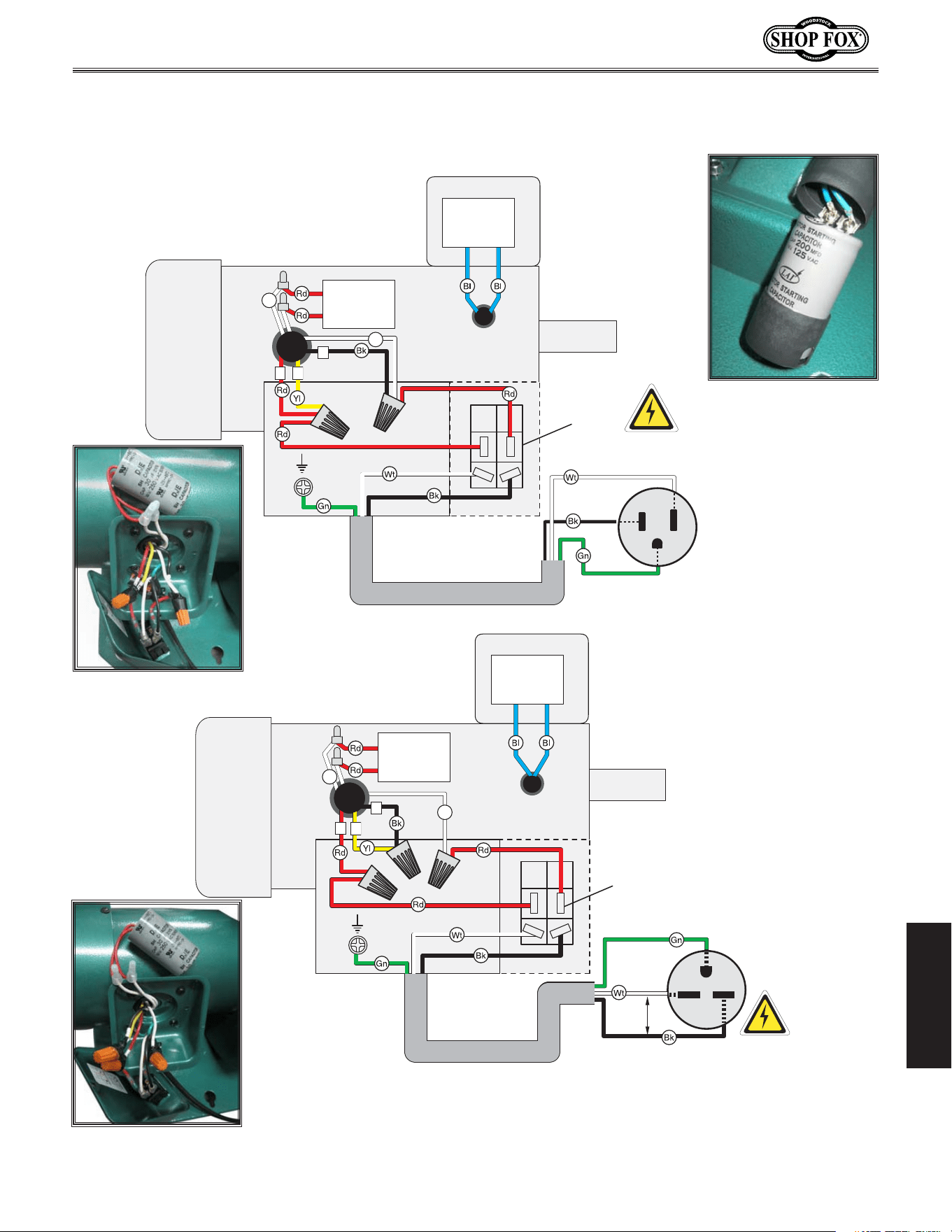
-25-
Df[\cN(/)-=fiDXZ_`e\jD]^%J`eZ\+&()
J<IM@:<
120 Volt Motor
(Prewired)
Ground
Paddle
Switch
Neutral
Hot
Ground
120 VAC
5-15 Plug
240 Volt Motor
(Rewired)
Paddle
Switch
Hot
Hot
Ground
6-15 Plug
(As Recommended)
240
VAC
<
Ground
Li
Li
Start
Capacitor
200MFD
125VAC
Run
Capacitor
30MFD
250VAC
Start
Capacitor
200MFD
125VAC
(
&
'
(
&
'
Run
Capacitor
30MFD
250VAC
Li
Li
Figure )). Start
capacitor.
Figure )(. 240V
junction box.
Figure )'. 120V
junction box.
N`i`e^;`X^iXd
-26-
Df[\cN(/)-=fiDXZ_`e\jD]^%J`eZ\+&()
J<IM@:<
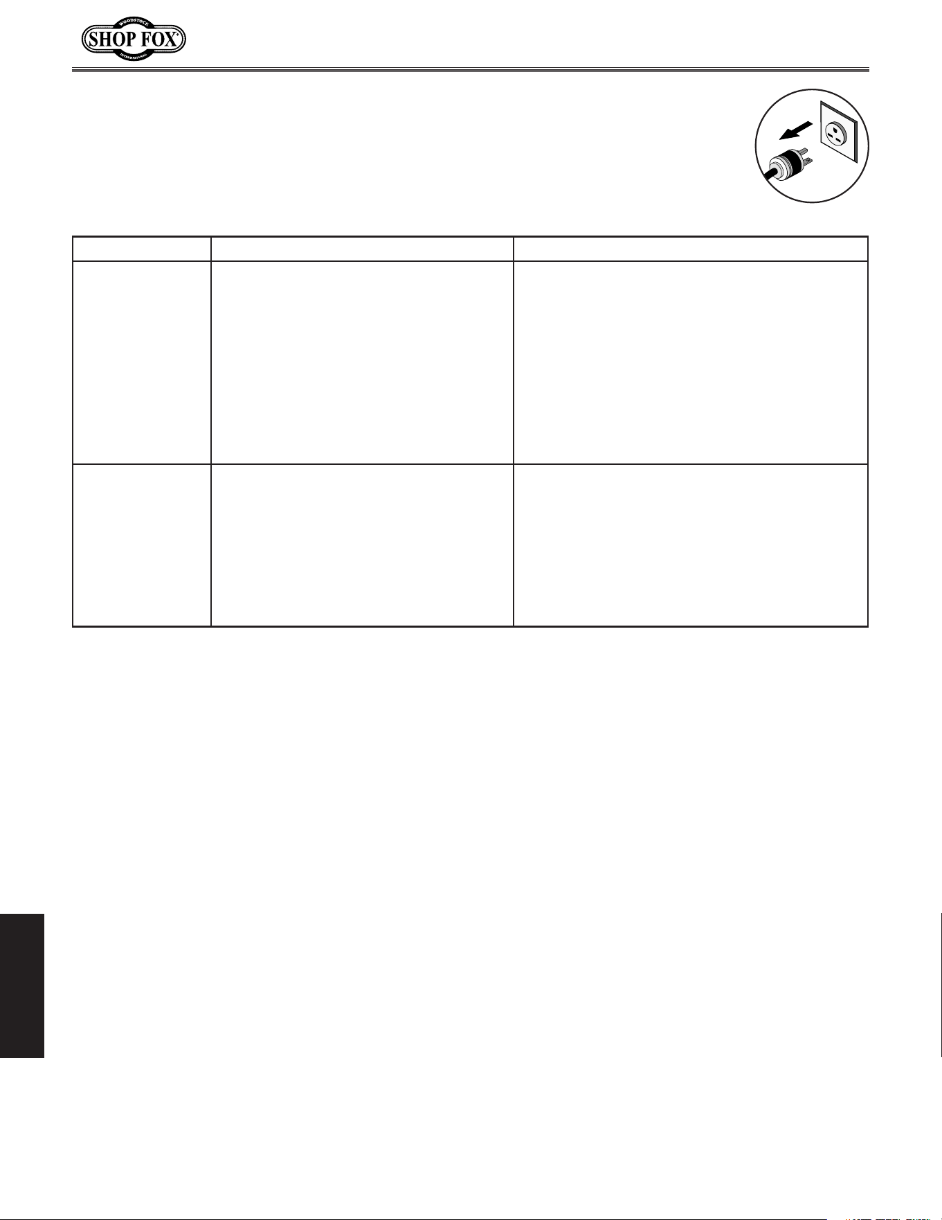
KiflYc\j_ffk`e^
This section covers the most common problems and corrections with this type of
machine. N8IE@E>;FEFKdXb\XepX[aljkd\ekjlek`cgfn\i`j[`jZfee\Zk\[Xe[
dfm`e^gXikj_Xm\Zfd\kfXZfdgc\k\jkfg
Dfkfi<c\Zki`ZXc
Symptom Possible Cause Possible Solution
Machine does not
start or a breaker
trips.
1. Switch disabling key removed.
2. Wall fuse/circuit breaker is blown/
tripped.
3. Power supply switched OFF or is at fault.
4. Wiring is open/has high resistance.
5. Motor ON/OFF switch is at fault.
6. Motor is at fault.
1. Install disabling key.
2. Verify that no short exists, and that the circuit size
is suitable for this machine; replace fuse/reset
breaker.
3. Ensure power supply is switched on; ensure power
supply has the correct voltage.
4. Check for broken wires or disconnected/corroded
connections, and repair/replace as necessary.
5. Replace faulty ON/OFF switch.
6. Test/repair/replace.
Machine has
vibration or noisy
operation.
1. Motor or component is loose.
2. Motor mount loose/broken.
3. Machine is incorrectly mounted to wall.
4. Motor fan is rubbing on fan cover.
5. Motor bearings are at fault.
1. Inspect/replace stripped or damaged bolts/nuts,
and re-tighten with thread locking fluid.
2. Tighten/replace.
3. Tighten/replace mounting hardware.
4. Replace dented fan cover; replace loose/damaged
fan.
5. Test by rotating shaft; rotational grinding/loose
shaft requires bearing replacement.
Troubleshooting
-27-
Df[\cN(/)-=fiDXZ_`e\jD]^%J`eZ\+&()
J<IM@:<
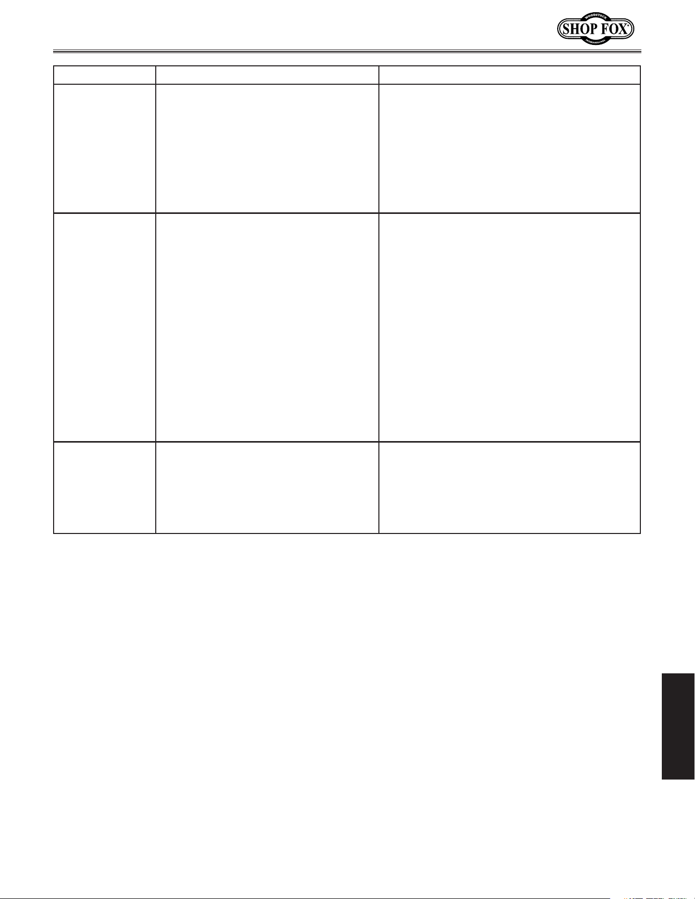
Symptom Possible Cause Possible Solution
Loud, repetitious
noise, or excessive
vibration coming
from dust collector.
1. Dust collector or component is loose.
2. Impeller is damaged and unbalanced.
3. The motor mounting or housing
connections are loose.
4. Impeller is loose on the motor shaft.
5. Motor fan cover is dented, causing the
motor fan to hit the cover while spinning.
1. Tighten/replace mounting hardware.
2. Disconnect dust collector from power, and inspect
the impeller for dents, bends, loose fins. Replace
impeller if any damage is found.
3. Make sure all fasteners on the dust collector are
tight.
4. Replace the motor and impeller as a set if the
motor shaft and the impeller hub are damaged.
5. Replace motor fan cover.
Dust collector does
not adequately
collect dust
or chips; poor
performance.
1. Dust collection bag is full.
2. There is a restriction in the duct line.
3. The dust collector is too far away from
the point of suction, or there are too
many sharp bends in the ducting.
4. The lumber is wet and dust is not flowing
through the ducting smoothly.
5. There is a leak in the ducting, or a series
of small leaks, or too many open ports.
6. The ducting and ports are incorrectly
sized.
7. The machine dust collection design is
inadequate.
8. The dust collector is too small for the dust
collection system.
1. Empty collection bag.
2. Remove dust line from dust collector inlet
and unblock the restriction in the duct line. A
plumbing snake may be necessary.
3. Relocate the dust collector closer to the point of
suction, and rework ducting without sharp bends.
Refer to Collection System, beginning on Page 16.
4. Process lumber with less than 20% moisture
content.
5. Rework the ducting to eliminate all leaks. Close
dust ports for lines not being used.
6. Reinstall correctly sized ducts and fittings. Refer
to Collection System beginning on Page 16 for
more solutions.
7. Use a dust collection nozzle on a stand, or
upgrade dust collection system.
8. Install a larger dust collector to power your dust
collection system.
Sawdust being
blown into the
air from the dust
collector.
1. Duct clamps or dust collection bag is not
properly clamped and secured.
2. Dust is extremely fine.
1. Re-secure ducts and dust collection bag, making
sure duct and bag clamps are tight and completely
over the ducts and bag.
2. Replace filter bag with Shop Fox Model D3632
0.3 micron type. Install one or more Shop Fox
Model W1690 Deluxe Ceiling Mounted 3 Speed Air
Cleaners.
-28-
Df[\cN(/)-=fiDXZ_`e\jD]^%J`eZ\+&()
G8IKJ
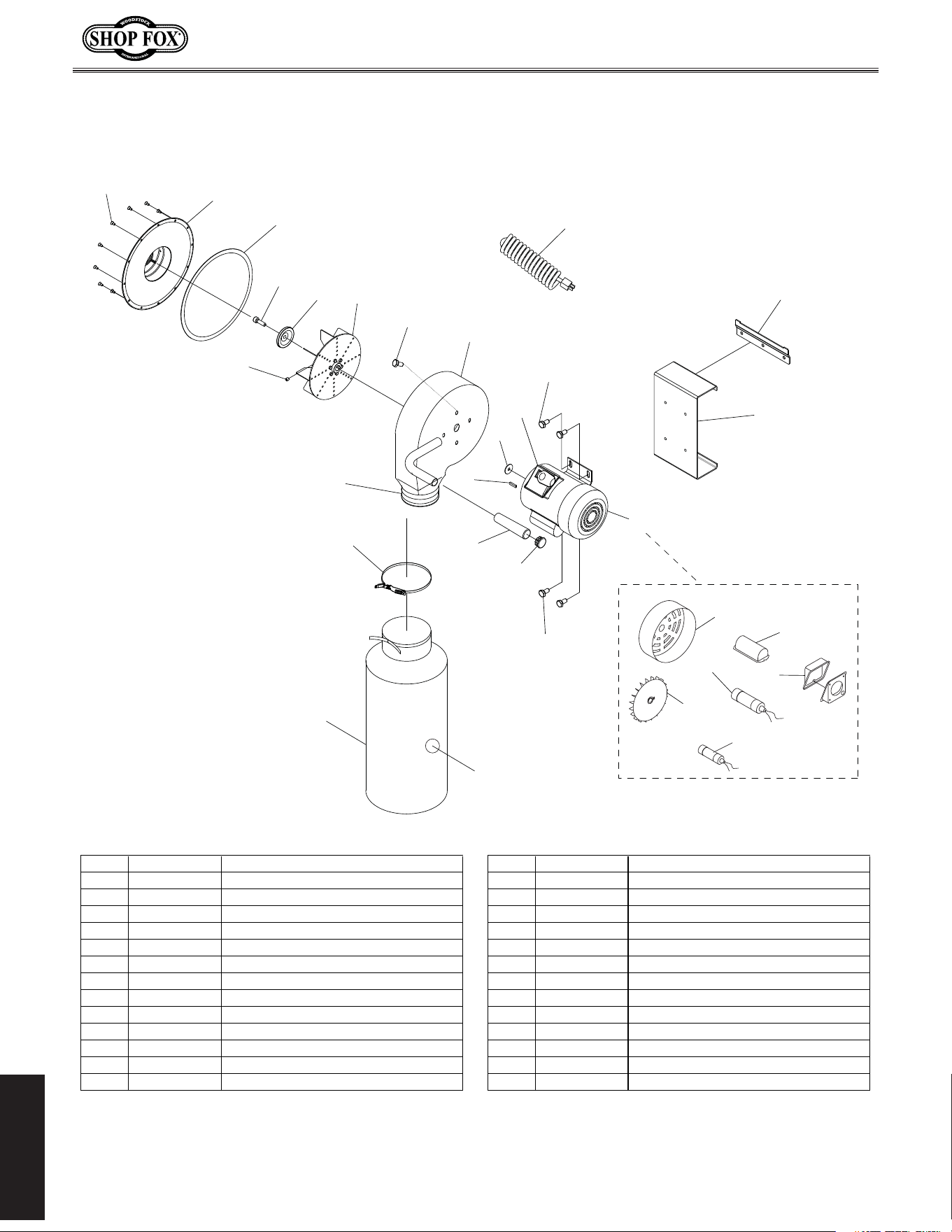
Jpjk\d
G8IKJ
&
'
(
)
*
+
,
-
.
&%
&&
&&"&
&&"'
&&"(
&&")
&&"*
&'
&(
&)
&*
''
&+
&,
&-
&.
&'
&'
'%
'&
&&"+
REF PART # DESCRIPTION REF PART # DESCRIPTION
1 X1826001 WALL BRACKET 11-4 XPC200 S CAPACITOR 200M 125V 1-1/4" X 3-3/8"
2 X1826002 MOTOR MOUNT BRACKET 11-5 X1826011-5 JUNCTION BOX
3 XPS09M PHLP HD SCR M5-.8 X 10 11-6 X1826011-6 R CAPACITOR 30M 250V 1-1/4" X 3-3/8"
4 X1826004 INLET COVER 11" 12 XPFB03 FLANGE BOLT 1/4-20 X 1/2
5 XPCAP121M CAP SCREW M6-1 X 20 LH 13 X1826013 PADDLE SWITCH W/KEY
6 X1826006 IMPELLER WASHER 6MM 14 X1826014 POWER CORD 16AWG 3C 5-15
7 X1826007 IMPELLER 10" 15 X1826015 COLLECTION BAG 13-1/2" X 24"
8 XPSS02 SET SCREW 5/16-18 X 3/8 16 XPK23M KEY 5 X 5 X 25
9 X1826009 COLLECTOR BODY W/HANDLE 17 X1826017 QUICK RELEASE BAG CLAMP
10 X1826010 MOTOR SHAFT SPACER 18 X1826018 HANDLE COVER
11 X1826011 MOTOR 1HP 110V/220V 1-PH 19 X1826019 HANDLE END CAP
11-1 X1826011-1 FAN COVER 20 X1826020 INLET COVER GASKET
11-2 X1826011-2 MOTOR FAN 21 X1826021 OUTLET GASKET
11-3 X1826011-3 CAPACITOR COVER 22 XPPAINT-1 SHOP FOX WHITE (M1006)
-29-
Df[\cN(/)-=fiDXZ_`e\jD]^%J`eZ\+&()
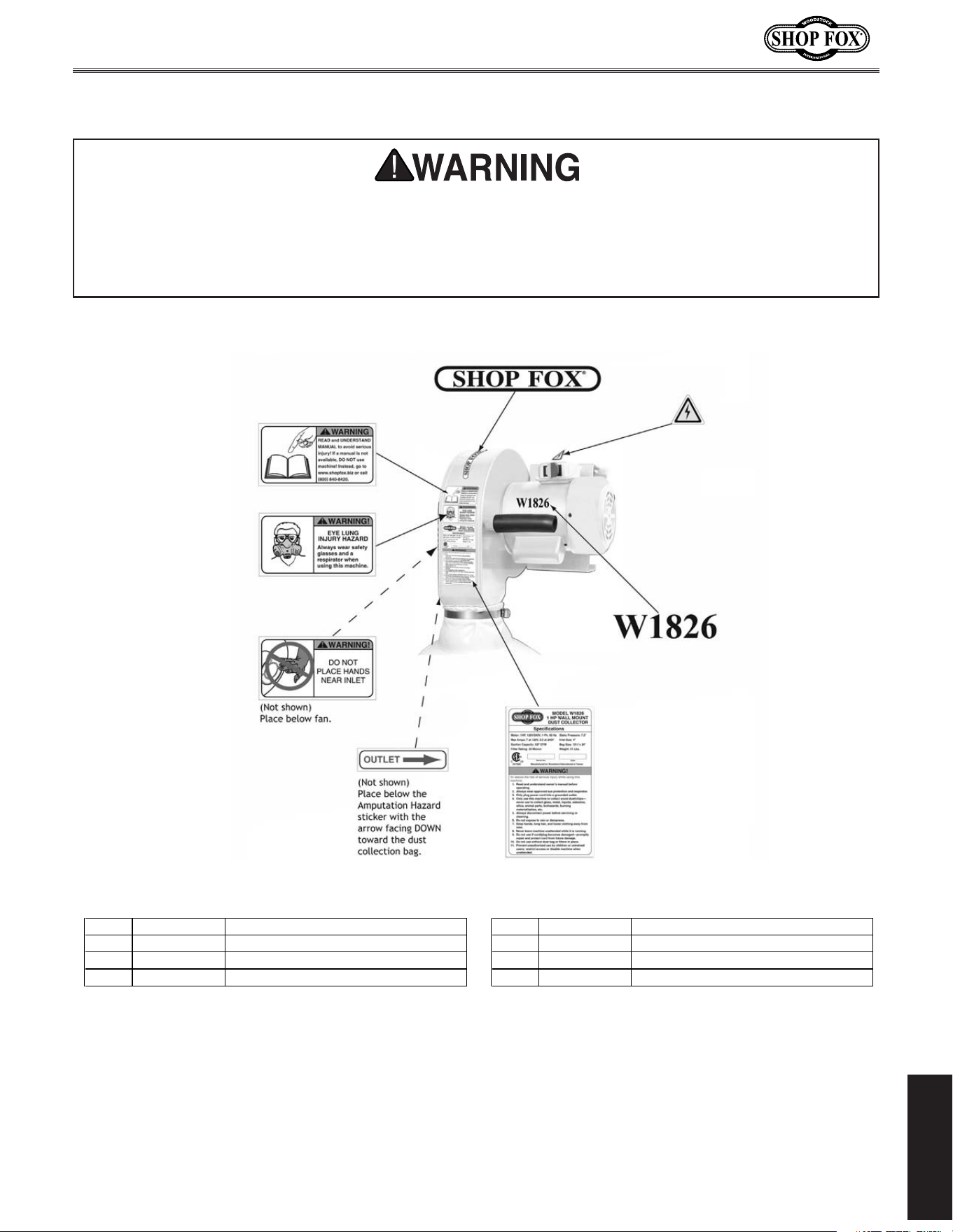
G8IKJ
CXY\cGcXZ\d\ek
JX]\kpcXY\cj nXie XYflk dXZ_`e\_XqXi[j Xe[ _fn kfgi\m\ek dXZ_`e\ [XdX^\fi `ealip% K_\
fne\i f] k_`j dXZ_`e\ DLJK dX`ekX`e k_\ fi`^`eXc cfZXk`fe Xe[ i\X[XY`c`kp f] Xcc cXY\cj fe k_`j
dXZ_`e\%@]XepcXY\c`ji\dfm\[fiY\Zfd\jlei\X[XYc\#I<GC8:<k_XkcXY\cY\]fi\Xccfn`e^k_\
dXZ_`e\kf\ek\ij\im`Z\X^X`e%:fekXZkNff[jkfZb@ek\ieXk`feXc#@eZ%Xk(*-').*+$*+/)fi
nnn%j_fg]fokffcj%Zfdkffi[\ie\ncXY\cj%
REF PART # DESCRIPTION REF PART # DESCRIPTION
23 XLABEL-08H READ MANUAL 3.8H X 2H 27 X1826027 MACHINE ID LABEL
24 XLABEL-06B RESPIRATOR/GLASSES 3.8W X 2H 28 X1826028 MODEL NUMBER LABEL
25 X1826025 HAND INLET WARNING LABEL 29 XLABEL-04 ELECTRICITY LABEL 1.4W X 1.2H
26 X1826026 OUTLET DIRECTION LABEL 30 X1826030 SHOP FOX LABEL
23
24
25
26
27
28
29
30


-31-

TAPE ALONG EDGES--PLEASE DO NOT STAPLE
FOLD ALONG DOTTED LINE
FOLD ALONG DOTTED LINE
NFF;JKF:B@EK<IE8K@FE8C@E:%
G%F%9FO)*'0
9<CC@E>?8D#N80/)).$)*'0
Place
Stamp
Here

N8II8EKP
Nff[jkfZb@ek\ieXk`feXc#@eZ%nXiiXekjXccJ_fg=fodXZ_`e\ipkfY\]i\\f][\]\Zkj]ifdnfibdXej_`g
Xe[dXk\i`Xcj]fiXg\i`f[f]knfp\Xij]ifdk_\[Xk\f]fi`^`eXcgliZ_Xj\Ypk_\fi`^`eXcfne\i%
K_`jnXiiXekp[f\jefkXggcpkf[\]\Zkj[l\[`i\Zkcpfi`e[`i\Zkcpkfd`jlj\#XYlj\#e\^c`^\eZ\fi
XZZ`[\ekj#cXZbf]dX`ek\eXeZ\#fii\`dYlij\d\ekf]k_`i[gXikp\og\ej\j`eZlii\[%
Nff[jkfZb@ek\ieXk`feXc#@eZ%n`cci\gX`ifii\gcXZ\#Xk`kj\og\ej\Xe[Xk`kjfgk`fe#k_\J_fg=fo
dXZ_`e\fidXZ_`e\gXik#n_`Z_`eefidXclj\_Xjgifm\ekfY\[\]\Zk`m\#gifm`[\[k_Xkk_\fi`^`eXc
fne\ii\kliejk_\gif[lZkgi\gX`[kfXJ_fg=fo]XZkfipj\im`Z\Z\ek\in`k_giff]f]k_\`igliZ_Xj\
f]k_\gif[lZkn`k_`eknfp\Xij#Xe[gifm`[\jNff[jkfZb@ek\ieXk`feXc#@eZ%i\XjfeXYc\fggfikle`kpkf
m\i`]pk_\Xcc\^\[[\]\Zkk_ifl^_`ejg\Zk`fe%@]`k`j[\k\id`e\[k_\i\`jef[\]\Zk#fik_Xkk_\[\]\Zk
i\jlck\[]ifdZXlj\jefkn`k_`ek_\jZfg\f]Nff[jkfZb@ek\ieXk`feXc@eZ%jnXiiXekp#k_\ek_\fi`^`eXc
fne\idljkY\Xik_\Zfjkf]jkfi`e^Xe[i\klie`e^k_\gif[lZk%
K_`j`jNff[jkfZb@ek\ieXk`feXc#@eZ%jjfc\ni`kk\enXiiXekpXe[XepXe[XccnXiiXek`\jk_XkdXp
Y\`dgc`\[YpcXn#`eZcl[`e^Xepd\iZ_XekXY`c`kpfi]`ke\jj#]fiXepgXik`ZlcXigligfj\#Xi\_\i\Yp
c`d`k\[kfk_\[liXk`fef]k_`jni`kk\enXiiXekp%N\[fefknXiiXekk_XkJ_fg=fodXZ_`e\ipZfdgc`\j
n`k_k_\gifm`j`fejf]XepcXnfiXZkj%@eef\m\ekj_XccNff[jkfZb@ek\ieXk`feXc#@eZ%jc`XY`c`kple[\i
k_`jnXiiXekp\oZ\\[k_\gliZ_Xj\gi`Z\gX`[]fik_\gif[lZk#Xe[Xepc\^XcXZk`fejYifl^_kX^X`ejk
Nff[jkfZb@ek\ieXk`feXc#@eZ%j_XccY\ki`\[`ek_\JkXk\f]NXj_`e^kfe#:flekpf]N_XkZfd%N\j_Xcc
`eef\m\ekY\c`XYc\]fi[\Xk_#`eali`\jkfg\ijfejfigifg\ikpfi]fi`eZ`[\ekXc#Zfek`e^\ek#jg\Z`Xcfi
Zfej\hl\ek`Xc[XdX^\jXi`j`e^]ifdk_\lj\f]fligif[lZkj%
<m\ip\]]fik_XjY\\edX[\kf\ejli\k_XkXccJ_fg=fodXZ_`e\ipd\\kj_`^_hlXc`kpXe[[liXY`c`kp
jkXe[Xi[j%N\i\j\im\k_\i`^_kkfZ_Xe^\jg\Z`]`ZXk`fejXkXepk`d\Y\ZXlj\f]fliZfdd`kd\ekkf
Zfek`elfljcp`dgifm\k_\hlXc`kpf]fligif[lZkj%
N8II8EKP

=^\]FjVa^inBVX]^cZhVcYIddah
LddYhidX`>ciZgcVi^dcVa!>cX#XVgg^Zhi]djhVcYhd[egdYjXihYZh^\cZY
idbZZii]ZcZZYhd[idYVnhlddYldg`ZghVcYbZiValdg`Zgh#
6h`ndjgYZVaZgVWdjii]ZhZ[^cZegdYjXih/