The user manual contains important safety information.
Please read and keep it for future reference.
We Are Here For You !
Support: [email protected]
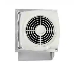
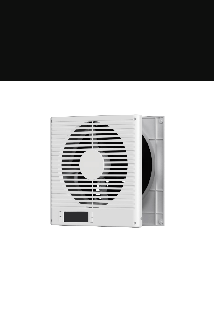
ROOM TO ROOM VENTILATION FAN
Windigaga
INSTRUCTION >>
Model: BT-RTR08-LCD

Important Safeguards
Specifications
Parts List
Product Overview
Installation Guide
Controller Operation
— Smart Controller
— Mode Programming
Remote Control
FAQ
Warranty
01
03
03
04
05
08
08
09
12
13
14
CONTENTS
IMPORTANT SAFEGUARDS
This symbol indicates important safety information. The accompanying illustration shows
a warning: "Be careful of electric shock."
Always unplug the fan before moving it to a different location.
Do not use the fan in or near a window. Exposure to rain may cause electrical hazards.
Do not damage, modify, excessively bend, pull, bind or place heavy objects on the power
cord. Doing so may cause electric leakage, fire, or electric shock.
If the fan will not be used for an extended period, unplug it from the power outlet.
If the power cord is damaged, do not attempt to repair it yourself.
Contact your local service center or a qualified electrician for replacement to avoid risk of
injury or damage.
Never insert fingers, pencils, or any other objects through the safety guard while the fan
is operating.
Do not attempt to disassemble, repair, or modify the unit while it is in operation. This can
lead to electric shock, fire, or personal injury.
Failure to follow these instructions may result in electric shock, fire, personal injury, or
damage to the unit.
When unplugging the fan, always hold the plug—do not pull the cord. Pulling the cord
may damage it and cause electric shock or fire.
Always disconnect the power before cleaning the fan.
WARNING
Use only with a power supply that matches the rated voltage. Using an incompatible
power source may cause fire or electric shock.
Stop using the fan immediately if you notice smoke, unusual odors, abnormal motor
sounds, or any other malfunction. Continued use may result in fire or electric shock.
CAUTION
- 01 -
Changes or modifications not expressly approved by the party responsible for compliance could
void the user's authority to operate the equipment. This equipment has been tested and found
to comply with the limits for a Class B digital device, pursuant to Part 15 of the FCC Rules. These
limits are designed to provide reasonable protection against harmful interference in a residential
installation. This equipment generates, uses, and can radiate radio frequency energy and, if not
installed and used in accordance with the instructions, may cause harmful interference to radio
communications. However, there is no guarantee that interference will not occur in a particular
installation. If this equipment does cause harmful interference to radio or television reception,
which can be determined by turning the equipment off and on, the user is encouraged to try to
correct the interference by one or more of the following measures:
- Reorient or relocate the receiving antenna.
- Increase the separation between the equipment and receiver.
- Connect the equipment into an outlet on a circuit different from that to which the receiver is
connected.
- Consult the dealer or an experienced radio/TV technician for help.
This device complies with part 15 of the FCC Rules. Operation is subject to the following two
conditions:
(1) This device may not cause harmful interference, and
(2) this device must accept any interference received, including interference that may cause
undesired operation.
FCC-ID: 2BCGA-BT-RTRO8-LCD
FCC Warning Statement:
- 02 -
SPECIFICATIONS
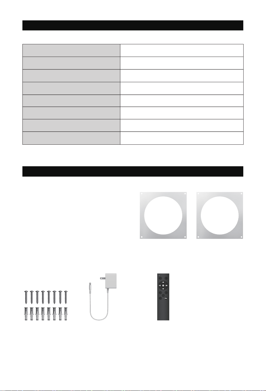
PARTS LIST
35%-85% RH
BT-RTR08-LCD
3.5 to 6.2 inches
14°F-120°F
320 CFM
Operating Humidity
Model No.
Compatible Wall Thickness
Operating Temperature
Product Dimensions 10.12 x 10.12 x 4.5 inches
10WPower
120V~ 60HzPower Supply
Maximum Airflow
Front Faceplate x1 Rear Faceplate x1
Front Faceplate
Stencil x1
Rear Faceplate
Stencil x1
Screws and
Anchors x8
Adapter x1 Remote Control x1
(Batteries not included)
User Manual x1
ON OFF
AUTO TIMER
F
/
R
CYCLE
- 03 -
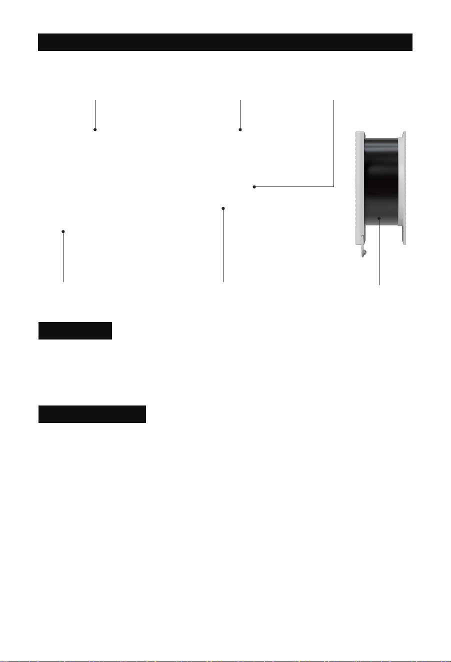
PRODUCT OVERVIEW
Heavy-Duty Build Next-Gen DC Motor Dual-Ball Bearings
Telescopic Wall-Fit Design
Two-Way AirflowSmart Controller
This model improves ventilation between rooms through wall fans, making it ideal for offices,
workshops, recreation rooms, laundry rooms, bedrooms, guest rooms, and other areas that
might not otherwise have access to proper airflow.
Application
Pwm Control Fans
The system utilizes high-performance DC motors controlled by PWM (Pulse Width Modulation).
This technology allows the dual fans to operate smoothly at extremely low RPM speeds without
generating motor or electromagnetic noise. Additionally, the fans feature blades designed with
a high static pressure rating, making them perfect for applications where airflow is restricted,
such as through ductwork. The motor housing allows the fan system to be mounted either
horizontally or vertically.
- 04 -
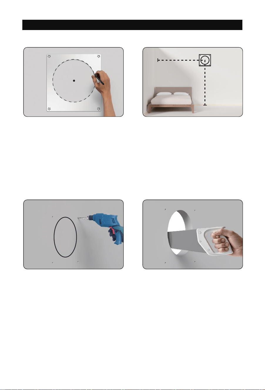
INSTALLATION GUIDE
From the center point, measure the distance
to the end of the wall (X) and the height to
the floor (Y).
Keep these measurements for Step 7.
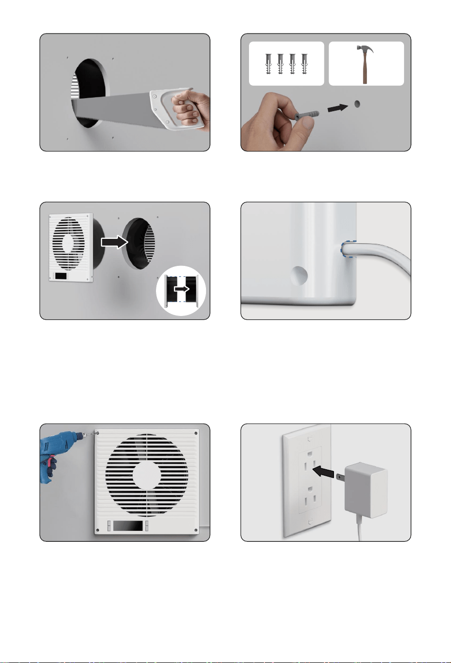
Step 2
Drill the mounting holes into the wall.
Cut the circular outline to create the opening using a saw for best results.
Step 3
Step 1
Choose a mounting location free of
obstructions (e.g., studs, waterlines,
electrical cords, etc.). Ensure the wall is
3.5 to 6.2 inches thick.
Use the rear faceplate stencil to mark
the center point, mounting points, and
the circular outline.
- 05 -
X
Y
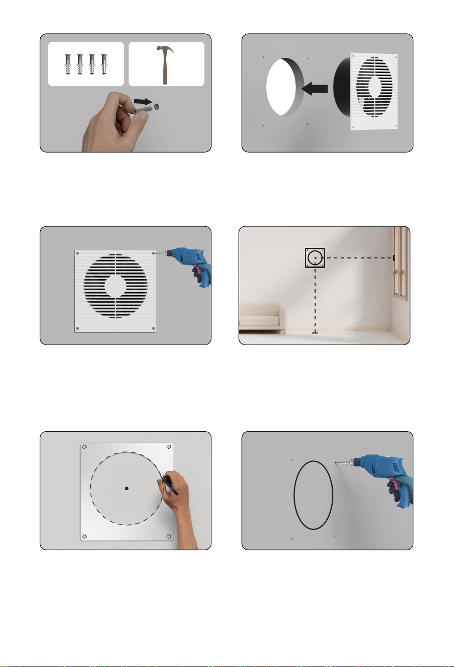
Step 8
Place the front faceplate stencil over
the center point, then mark the mounting
points and circular outline.
Step 9
Drill the mounting holes into the wall.
Cut the circular outline to create the opening.
Again, using a saw is recommended.
Step 4
Insert the included anchors into the
mounting holes.
Step 5
Position the rear faceplate into the circular
cutout, ensuring the mounting holes align.
Step 6
Secure the rear faceplate by drilling the
screws into the anchors.
Step 7
On the opposite side of the wall, mark the
center point using the length (X) and height
(Y) from Step 2.
- 06 -
X
Y
Step 10
Insert the included anchors into the mounting holes.
Step 11
Insert the front faceplate into the circular
cutout, ensuring the mounting holes align.
The cylinder should easily slide into the rear
faceplate's cylinder.
Step 12
Route the power cord through the opening
at the lower right corner to ensure the front
faceplate is flush against the wall.
Step 13
Secure the front faceplate by drilling the
screws into the anchors.
Step 14
Insert the power adapter cable into the unit's
power socket. Then, plug the AC power cord
into a wall outlet to power the fan.
- 07 -
CONTROLLER OPERATION
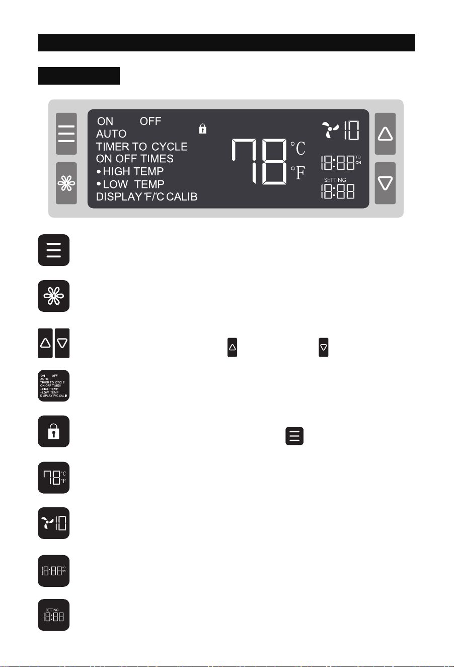
MODE Button
Cycles through the controller’s modes: ON, OFF, AUTO (HIGH / LOW TEMP), TIMER
(TIMER TO ON / OFF), and CYCLE (ON / OFF / CYCLE TIMES).
SETTING Button
Cycles through the controller’s settings: DISPLAY, °F/°C, CALIB, and F/R (airflow
direction).
UP / DOWN Buttons
Adjusts values in the selected mode. increases the value, decreases it.
Controller Mode / Setting
Displays the current operating mode or setting.
Child Lock
Indicates when Child Lock is enabled. Press and hold for 3 seconds to toggle.
Smart Controller
Sensor Temperature
Displays the current room temperature.
Fan Speed Level
Displays the current fan speed level.
Countdown
Shows remaining time in TIMER mode (TIMER TO ON / OFF) or remaining cycles in
CYCLE TIMES mode.
User Settings
Displays the current value for the selected mode.
- 08 -
Mode Programming
NOTE 1: Each mode functions independently. Only one mode can be active at a time.
NOTE 2: Mode settings are automatically saved, so there is no need to reconfigure after restart-
ing the device.
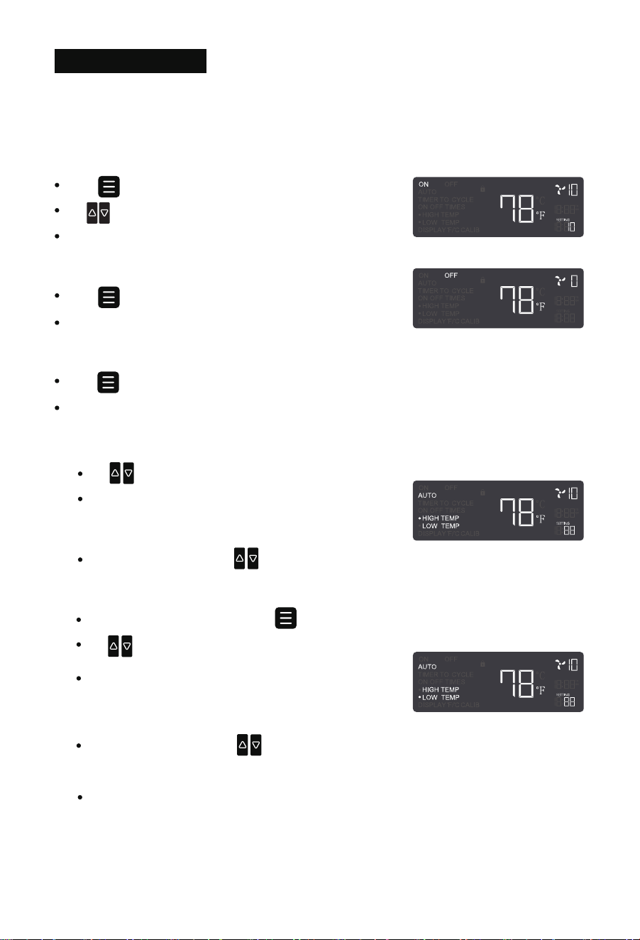
ON Mode
Press to select ON mode.
Use to adjust the fan speed level (0-10).
The speed set in this mode also applies to other modes.
OFF Mode
Press to select OFF mode.
The fan will stop, and the speed will display as “0”.
3. Auto Range Setting ( Factory setting )
NOTE:
To operate the fan within a specific temperature range, set the HIGH TEMP trigger lower
than the LOW TEMP trigger. The fan will only work if the sensor temperature stays
within this range.
1. Both HIGH TEMP and LOW TEMP must be enabled for this function.
2. Factory setting is Auto range setting
AUTO Mode
Press to enter AUTO mode.
When either HIGH TEMP or LOW TEMP is enabled, the correspondingindicator will flash.
1. AUTO HIGH TEMP
Use to set the HIGH TEMP trigger.
The fan will activate when the room temperature rises
above the set value and gradually increase to the speed
set in ON mode.
While in HIGH TEMP mode, press again to enter LOW TEMP.
Use to set the LOW TEMP trigger.
2. AUTO LOW TEMP
The fan will activate when the room temperature
falls below the set value and gradually increase to
the speed set in ON mode.
To disable, press and hold simultaneously for 3 seconds.
To disable, press and hold simultaneously for 3 seconds.
- 09 -
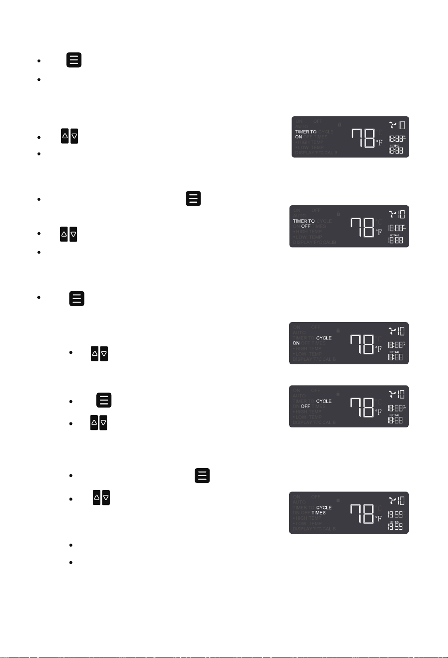
TIMER Mode
Press to enter TIMER mode.
This is a standalone mode used to set fan turn-on or turn-off timers. It cannot be used
together with other modes.
TIMER TO ON
Use to set a startup countdown (max: 19h59min).
After the countdown, the fan runs at the ON mode speed.
Use to set a shutdown countdown (max: 19h59min).
The fan stops when the countdown ends.
While in TIMER TO ON mode, press again to enter
TIMER TO OFF.
TIMER TO OFF
— Step 1 CYCLE ON
Use to set the ON duration (max: 19h59min).
CYCLE Mode
Press to enter CYCLE mode. Set alternating ON and OFF durations for automatic
cycling.
— Step 3 CYCLE TIMES
After setting CYCLE OFF, press again to enter CYCLE TIMES.
The fan will stop when the countdown reaches “0”.
“---” means unlimited continuous cycling based on ON/OFF durations.
Use to adjust the number of cycles (max:
1999). The setting will confirm automatically
after 3 seconds of inactivity.
— Step 2 CYCLE OFF
Press again to enter CYCLE OFF.
Use to set the OFF duration (max: 19h59min).
- 10 -
— F (Forward Airflow)–Fan icon spins clockwise
— R (Reverse Airflow)–Fan icon spins counterclockwise
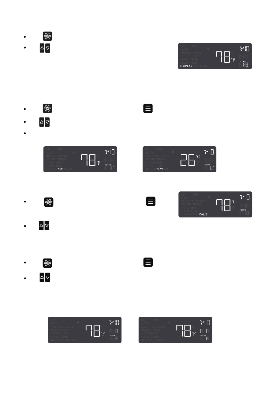
Press to enter DISPLAY settings, then press to select °F / °C.
Use to switch between Fahrenheit ( °F ) and Celsius ( °C ).
All temperature readings will update accordingly.
Press to enter DISPLAY settings.
Use to switch brightness: Level 1, 2, 3, or “A3”.
— Level 3 = Maximum brightness
— Level 1 = Minimum brightness
— “A3” turns off the screen after 30 seconds of inactivity, while the fan keeps running.
°F / °C Settings
DISPLAY Settings
Press to enter DISPLAY settings, then press to
select CALIB.
Use to manually calibrate the sensor temperature in 1-unit increments (range: -9 to 9) to
match the actual temperature.
CALIB Settings
F/R Settings
Press to enter DISPLAY settings, then press to select F/R.
Use to adjust airflow direction:
- 11 -
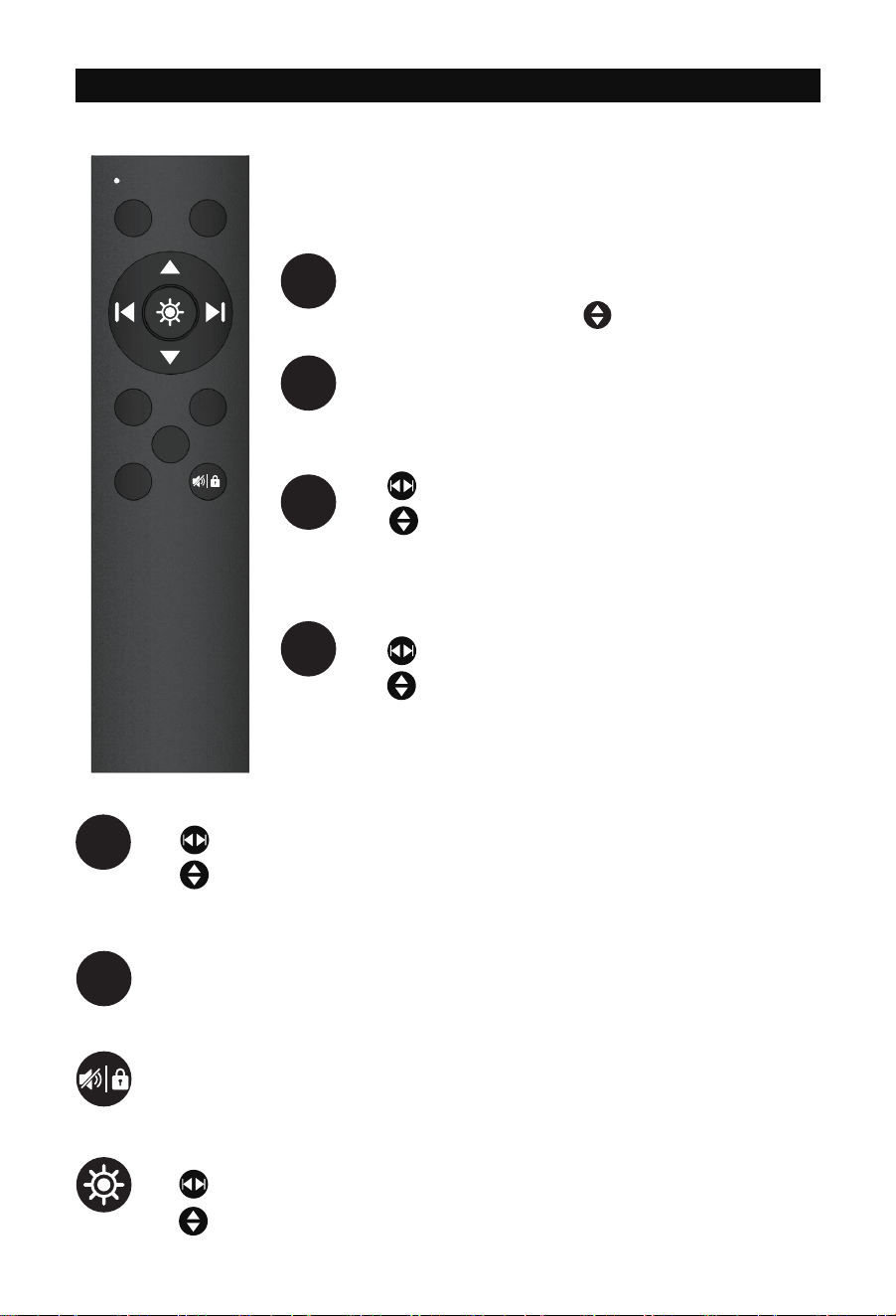
REMOTE CONTROL
Press and hold for 5 seconds to pair the remote (beep
confirms).
Press to enter ON mode. Use to adjust the fan speed.
Press to enter OFF mode. The fan will stop running.
Press to enter AUTO mode.
Use to select HIGH TEMP or LOW TEMP.
Use to set the trigger temperature. To disable HIGH
TEMP or LOW TEMP, set the value to OFF (between 0 and -1).
NOTE: Batteries are not included. Install 2 AAA batteries before
using the remote.
ON OFF
AUTO TIMER
F
/
R
CYCLE
AUTO
ON
OFF
Press to enter TIMER mode.
Use to select TIMER TO ON or TIMER TO OFF.
Use to set the countdown.
Press to enter CYCLE mode.
Use to select ON, OFF, or CYCLE TIMES.
Use to set duration or cycle count.
Press to adjust airflow direction:
F (Forward Airflow)–Fan icon spins clockwise
R (Reverse Airflow)–Fan icon spins counterclockwise
Press to toggle buzzer sound.
Press and hold for 3 seconds to enable/disable child lock.
Press to enter DISPLAY settings.
Use to adjust brightness.
Use to switch between °F/ °C , CALIB, or F/R settings.
F/R
TIMER
CYCLE
- 12 -

FAQS
The remote requires 2 AAA batteries (not included in the package). Please do not use
rechargeable batteries.
Ensure that the plug is securely connected to the outlet. If the issue persists, try using a
different power outlet. If the fan still does not turn on, please contact our customer
support team for assistance.
Q1 Why isn’t the remote control working?
b.
The remote may not have been paired successfully. Press and hold ON button on the
remote for 5 seconds until you hear a beep, indicating successful pairing.
a.
c.
If the problem persists, please contact our customer support team for assistance.
Q4 Why doesn't the fan work in AUTO mode when the set high or low temperature is
reached?
b.
Check if the LOW TEMP trigger is set higher than the HIGH TEMP trigger. If so, the fan will
only work within that specific temperature range. Disabling either the HIGH TEMP or LOW
TEMP will restore normal operation.
a.
Disconnect the power supply before cleaning or servicing the fan.
Q5 How do I perform maintenance on this fan?
Step 1
Unscrew the bolts and remove the front grilles and fan blades.Step 2
Wipe the exterior with a dry cloth or use a light vacuum to remove dust.Step 4
Clean the grilles and blades with warm, soapy water and a soft cloth. Do not use
abrasive cleaners, wire brushes, or steel wool.
Step 3
We recommend the following tools for installation: pencil, ruler, tape measure, screw-
driver, drill, drywall saw, and stud finder.
Q2 What tools do I need to install this fan?
a.
You can install the fan in any desired location, except for windows, fire-rated walls, or
exterior walls, as exposure to rain could cause product damage.
Q3 Where can I install this fan?
a.
- 13 -

FCC-ID: 2BCGA-BT-RTRO8-LCD
WARRANTY
Windigaga warrants this product to be free of defects in material and workmanship for the
applications specified in the Owner's Manual for a period of 24 months from date of
purchase.This warranty only applies to the original purchaser of this product.
Support: [email protected]
※ Please have your order ID ready before contacting Customer Support
If you have any questions, you are welcome to contact us via email! We will get back to you
within 24 hours.
- 14 -