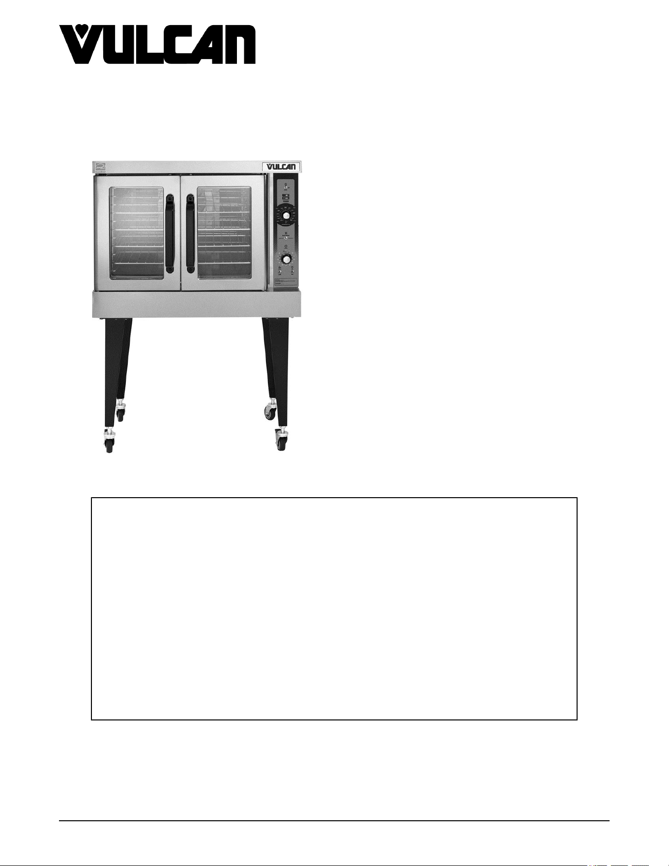
VC4G & VC6G SERIES FULL SIZE
CONVECTION OVENS
VC4GS ML-126610
VC4GD ML-126611
VC4GC ML-136494
VC6GS ML-126612
VC6GD ML-126613
VC6GC ML-136495
- NOTICE -
This Manual is prepared for the use of trained Hobart Service Technicians and should not
be used by those not properly qualified.
This manual is not intended to be all encompassing. If you have not attended a Hobart Service
School for this product, you should read, in its entirety, the repair procedure you wish to
perform to determine if you have the necessary tools, instruments and skills required to
perform the procedure. Procedures for which you do not have the necessary tools,
instruments and skills should be performed by a trained Hobart Service Technician.
The reproduction, transfer, sale or other use of this manual, without the express written
consent of Hobart, is prohibited.
This manual has been provided to you by ITW Food Equipment Group LLC ("ITW FEG")
without charge and remains the property of ITW FEG, and by accepting this manual you agree
that you will return it to ITW FEG promptly upon its request for such return at any time in the
future.
SERVICE MANUAL
A product of Vulcan-Hart 3600 North Point Blvd Baltimore, MD 21222
F24682 Rev. J (0825)

TABLE OF CONTENTS
SERVICE UPDATES ....................................................................................... 4
SERVICE UPDATES - VC4G / VC6G ................................................................... 4
TIS DOCUMENT LIST - VC4G AND VC6G .............................................................. 4
GENERAL .................................................................................................. 6
INTRODUCTION ....................................................................................... 6
INSTALLATION, OPERATION AND CLEANING ......................................................... 6
OPERATION ........................................................................................... 6
CLEANING ............................................................................................. 6
REFERENCE INFORMATION .......................................................................... 6
LUBRICATION ......................................................................................... 6
SPECIFICATIONS ...................................................................................... 6
TOOLS ................................................................................................. 6
REMOVAL AND REPLACEMENT OF PARTS ............................................................... 7
COVERS AND PANELS ................................................................................ 7
TOP FRONT COVER ............................................................................... 7
BOTTOM FRONT COVER
.......................................................................... 7
CONTROL PANEL ................................................................................. 7
RIGHT SIDE PANEL ................................................................................ 7
CONTROL PANEL COMPONENTS ..................................................................... 8
COMPONENT PANEL COMPONENTS ................................................................. 8
TEMPERATURE PROBE ............................................................................... 9
GAS BURNER ......................................................................................... 9
GAS ORIFICE ......................................................................................... 10
GAS SOLENOID VALVE .............................................................................. 11
IGNITION CONTROL MODULE ....................................................................... 12
SPARK IGNITER AND FLAME SENSE ................................................................ 12
BLOWER AND MOTOR ENDING AT SERIAL NUMBER 481913935 .................................... 13
BLOWER AND MOTOR ............................................................................... 14
OVEN DOORS (SIMULTANEOUS DOORS) ENDING AT SERIAL NUMBER 481907145 ................ 16
ASSEMBLY REMOVAL ........................................................................... 16
DISASSEMBLY ................................................................................... 17
OVEN DOORS (SIMULTANEOUS DOORS) ........................................................... 17
OVEN DOORS AND BEARINGS (INDEPENDENT DOORS) ENDING AT SERIAL
NUMBER 481907145 .............................................................................. 18
DOOR CATCH BALL ASSEMBLY (INDEPENDENT DOORS) ........................................... 19
OVEN DOORS (INDEPENDENT DOORS) STARTING AT SERIAL NUMBER 481907146 ............... 19
ROLLER LATCH ASSEMBLY (INDEPENDENT DOORS) ............................................... 20
DOOR WINDOW ...................................................................................... 20
DOOR SWITCH ....................................................................................... 21
MECHANICAL KX THERMOSTAT (VC4GS/6GS) ...................................................... 21
HIGH LIMIT THERMOSTAT ........................................................................... 22
INTERIOR LIGHTS (REAR MOUNTED, ROUND) ...................................................... 22
INTERIOR LIGHTS (SIDE MOUNTED, SQUARE) ...................................................... 23
COOLING FAN ........................................................................................ 25
SERVICE PROCEDURES AND ADJUSTMENTS ........................................................... 26
SOLID STATE TEMPERATURE CONTROL CALIBRATION ............................................ 26
MECHANICAL THERMOSTAT CALIBRATION (VC4GS/6GS) .......................................... 27
SOLID STATE TEMPERATURE CONTROL TEST ..................................................... 28
TEMPERATURE PROBE TEST ....................................................................... 29
GAS PRESSURE ADJUSTMENT (UNITS UP TO FEBRUARY 2015) ................................... 29
GAS VALVE PRESSURE CHECK ..................................................................... 31
VERIFICATION OF SPARK AT IGNITOR .............................................................. 32
DOOR SWITCH ADJUSTMENT ....................................................................... 32
BLOWER ADJUSTMENT .............................................................................. 33
VC4G & VC6G SERIES FULL SIZE CONVECTION OVENS
F24682 Rev. J (0825) Page 2 of 86

DOOR ADJUSTMENT ................................................................................. 33
DOOR STRIKE ADJUSTMENT (INDEPENDENT DOORS) ............................................. 34
DOOR CATCH BALL ADJUSTMENT (INDEPENDENT DOORS) ........................................ 35
DOOR CHAIN ADJUSTMENT (SIMULTANEOUS DOORS) ............................................. 36
INTRODUCTION .................................................................................. 36
PROCEDURE ..................................................................................... 36
COMPUTER CONTROL (VC4GC/VC6GC) ............................................................. 37
OPERATION ...................................................................................... 37
SETUP MODE .................................................................................... 37
PROBE TEST ..................................................................................... 38
SOLID STATE RELAY TEST
...................................................................... 38
COMPUTER CONTROL CALIBRATION FOR WATLOW CONTROLLER (VC4GC/VC6GC) .............. 38
FLAME SENSE CURRENT TEST ...................................................................... 39
SERVICE PROGRAMMING AND TESTING FOR 3700 COMPUTER CONTROL ........................ 42
CONVECTION MOTOR CENTRIFUGAL SWITCH (TEST) .............................................. 45
ELECTRICAL OPERATION ................................................................................ 46
COMPONENT LAYOUT AND FUNCTION .............................................................. 46
COMPONENT LAYOUT AND FUNCTION - STARTING SN 482080151 ................................. 48
COMPONENT LOCATION ............................................................................. 50
SEQUENCE OF OPERATION ......................................................................... 51
WKGD WITH ROAST & HOLD OPTION (SOLID STATE TEMPERATURE CONTROL) .............. 51
SCHEMATICS ............................................................................................ 54
VC4GS, VC6GS MECHANICAL (KX) CONTROLS ..................................................... 54
VC4GS, VC6GS MECHANICAL (KX) CONTROLS, ROAST & HOLD OPTION ........................... 55
VC4GD, VC6GD SOLID STATE TEMPERATURE CONTROL .......................................... 56
VC4GD, VC6GD SOLID STATE TEMPERATURE CONTROL, ROAST & HOLD OPTION ................ 62
VC4GC, VC6GC COMPUTER CONTROL (ROAST & HOLD STANDARD) .............................. 63
VC4GD & VC6GD, VC WITH STANDING PILOT 120 & 200 VOLT ...................................... 65
WIRING DIAGRAMS ...................................................................................... 67
VC4GS, VC6GS MECHANICAL (KX) CONTROLS ..................................................... 67
VC4GS, VC6GS MECHANICAL (KX) CONTROLS, ROAST & HOLD OPTION ........................... 69
VC4GD, VC6GD SOLID STATE TEMPERATURE CONTROL .......................................... 71
VC4GD, VC6GD SOLID STATE TEMPERATURE CONTROL, ROAST & HOLD OPTION ................ 75
VC4GC, VC6GC COMPUTER CONTROL (ROAST & HOLD STANDARD) .............................. 77
VC4GD & VC6GD, VC WITH STANDING PILOT 120 & 200 VOLT ...................................... 79
TROUBLESHOOTING ..................................................................................... 82
ALL MODELS ......................................................................................... 82
IGNITION MODULE DIAGNOSTICS ................................................................... 83
COMPUTER CONTROL MODELS ONLY .............................................................. 84
ERROR CODES .................................................................................. 85
MECHANICAL CONTROLS TROUBLESHOOTING .................................................... 86
VC4G & VC6G SERIES FULL SIZE CONVECTION OVENS
© VULCAN 2025
Page 3 of 86 F24682 Rev. J (0825)
SERVICE UPDATES
SERVICE UPDATES - VC4G / VC6G
August 2025
•
Added
MECHANICAL CONTROLS
TROUBLESHOOTING.
•
Added
CONVECTION MOTOR CENTRIFUGAL
SWITCH (TEST).
March 2025
•
Added
COMPONENT LAYOUT AND
FUNCTION - STARTING SN 482080151.
•
Updated
VC4GD, VC6GD Solid State
Temperature Control in SCHEMATICS.
•
Updated
VC4GD, VC6GD Solid State
Temperature Control in WIRING DIAGRAMS.
•
Updated
VC4GD & VC6GD, VC With Standing
Pilot 120 & 200 VOLT.
September 2024
•
Updated
SPECIFICATIONS.
June 2021
•
Added
Fig. 106.
March 2020
•
Added
VC4GD & VC6GD, VC With Standing
Pilot 120 & 200 VOLT.
June 2019
•
Added
SERVICE PROGRAMMING AND
TESTING FOR 3700 COMPUTER CONTROL.
October 2018
Updated and Added Data Modules
• BLOWER AND MOTOR
• OVEN DOORS (SIMULTANEOUS DOORS)
• OVEN DOORS (INDEPENDENT DOORS)
Starting at Serial Number 481907146
• INTERIOR LIGHTS (Side Mounted, Square)
• INTERIOR LIGHTS (Rear Mounted, Round)
• DOOR ADJUSTMENT
• COMPONENT LOCATION
• FLAME SENSE CURRENT TEST
• VC4GS, VC6GS Mechanical (KX) Controls,
Roast & Hold Option
• VC4GD, VC6GD Solid State Temperature
Control
• VC4GC, VC6GC Computer Control (Roast &
Hold Standard)
• IGNITION MODULE DIAGNOSTICS
TIS DOCUMENT LIST - VC4G AND VC6G
SERVICE TAB
Document Title Document Type
VC4G and VC6G Service Manual Service Manual
Watlow Controller Replaced By NCC Controller Technical Service Bulletin (TSB)
SERVICE TAB (Multimedia)
Document Title Document Type
DID You Know - VC4GD Misc.
3700 Oven Quick Start Guide Operator
Repair Flood-Damaged Food Equipment Misc
Convection Oven Computer Control Guide Operator
VC4GD, VC4GC, VC6GD, VC6GC, HGC5, HGC5X,
HGC5D, HGC5DX, & WKGD Installation and Operation
I &O Manual
Fundamentals of Gas Service Instructions
TSB 1037A Hobart to Vulcan "Common" Model Cross
Reference List
Technical Service Bulletin (TSB)
VC4G & VC6G SERIES FULL SIZE CONVECTION OVENS - SERVICE UPDATES
F24682 Rev. J (0825) Page 4 of 86
SERVICE TAB (Multimedia)
Technical Service Bulletin (TSB)
Rating Plate Locations on Current Vulcan-Hart/Wolf
Range Equipment
Service Bulletin
PARTS TAB
Document Title Document Type
Part Catalog for VC4G and VC6G Parts Catalog
DIAGRAMS TAB
Document Title Document Type
HGC5, DGC5, VC4G, WKGD Series Wiring Diagram
VC4G & VC6G SERIES FULL SIZE CONVECTION OVENS - SERVICE UPDATES
Page 5 of 86 F24682 Rev. J (0825)
GENERAL
INTRODUCTION
Procedures in this manual will apply to all models unless specified. Pictures and illustrations can be of any model
unless the picture or illustration needs to be model specific.
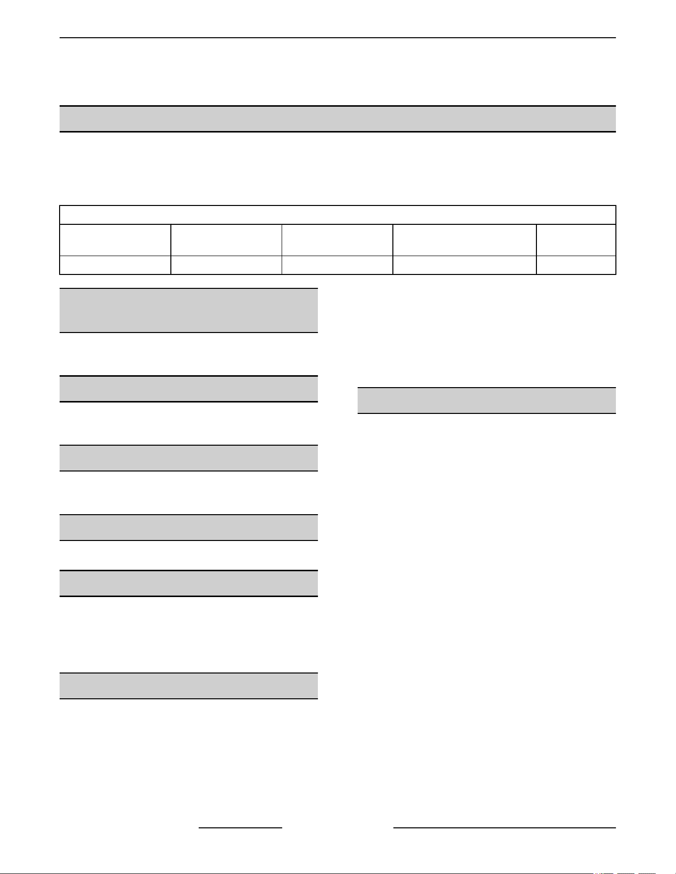
FEATURES
MODEL CAVITY DEPTH
TEMPERATURE
CONTROL
DOORS (50/50) COOK TIMER
WCGD 26.5" Solid State Simultaneus 1-Hour Dial
INSTALLATION, OPERATION AND
CLEANING
Refer to the Instruction Manual for detailed installation
instructions on single or stacked ovens.
OPERATION
Refer to the Instructions Manual for specific operating
instructions.
CLEANING
Refer to the Instructions Manual for specific cleaning
instructions.
REFERENCE INFORMATION
Refer to the Parts Catalog for parts information.
LUBRICATION
• Cavity blower motor has sealed bearings and
requires no additional lubrication.
•
Huskey™ TF-1000 grease or equivalent high
temperature Teflon grease.
SPECIFICATIONS
Electrical
Voltage - 120/60/1
Amps - 8.0 Amps
Input BTU Rating
Natural Gas - 50,000 BTU input at 5 in. W.C.
Propane Gas - 50,000 BTU input at 10 in. W.C.
Gas Line Pressures
Natural - Recommend (in W.C.) 8.0, Min 6.0
Propane - Recommend (in. W.C.) 11.0, Min 11
Maximum 14.0 in. W.C. (Nat. or Prop.)
TOOLS
Standard
•
Standard set of hand tools
• VOM with ability to measure micro amp current
VOM with minimum of NFPA-70E CAT III 600V,
UL/CSA/TUV listed. Sensitivity of at least 20,000
ohms per volt. Meter leads must also be rated at
CAT III 600V.
• Gear Puller to remove blower
Special
• Temperature tester (thermocouple type)
• Manometer
VC4G & VC6G SERIES FULL SIZE CONVECTION OVENS - GENERAL
F24682 Rev. J (0825) Page 6 of 86
REMOVAL AND REPLACEMENT OF PARTS
COVERS AND PANELS
Disconnect the electrical power to
the machine and follow lockout /
tagout procedures.
SHUT OFF THE GAS BEFORE SERVICING THE
UNIT.
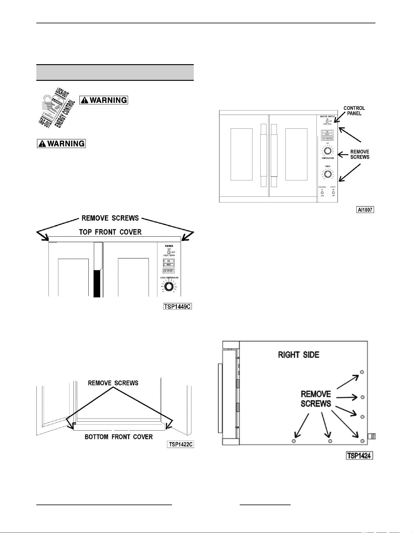
Top Front Cover
1.
The top front cover is secured with four (4)
screws, two on each side of cover. Remove these
screws then remove the cover from the oven.
Fig. 1
2. Reverse the procedure to install.
Bottom Front Cover
1. The bottom front cover is secured with four (4)
screws, two on each side of cover. Remove these
screws then remove the cover from the oven.
Fig. 2
2.
Reverse the procedure to install.
Control Panel
1. Remove
three (3) screws on the right side which
secure the control panel then pull the panel away
from the oven.
Fig. 3
2. Disconnect
the temperature probe leads from the
solid state temperature control.
3. Unplug the wire harness connector to the control
panel components.
4. Reverse the procedure to install.
Right Side Panel
1. Remove the screws which secure the right side
of the top front cover, bottom front cover and
control panel.
2. Remove the remaining six screws securing the
right side panel.
Fig. 4
3.
Pull the right side panel out at the bottom then
down to remove.
VC4G & VC6G SERIES FULL SIZE CONVECTION OVENS - REMOVAL AND REPLACEMENT OF PARTS
Page 7 of 86 F24682 Rev. J (0825)
4. Reverse the procedure to install.
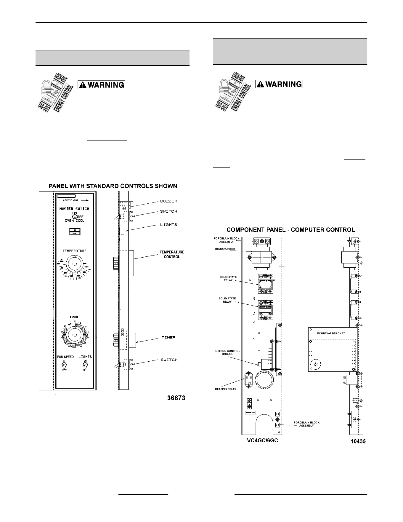
CONTROL PANEL COMPONENTS
Disconnect the electrical power to
the machine and follow lockout /
tagout procedures.
Removable Components Procedure
1.
Remove the
Control Panel.
2.
Remove the component being replaced.
3. Reverse the procedure to install the replacement
component, then check oven for proper
operation.
Fig. 5
COMPONENT PANEL
COMPONENTS
Disconnect the electrical power to
the machine and follow lockout /
tagout procedures.
Removable Components Procedure
1.
Remove the
Right Side Panel.
NOTE: If right side panel is not accessible, this
component can be serviced by removing the Control
Panel.
2.
Disconnect the wire leads to the component
being replaced.
3. Remove the component.
4. Reverse the procedure to install the replacement
component and check oven for proper operation.
Fig. 6
VC4G & VC6G SERIES FULL SIZE CONVECTION OVENS - REMOVAL AND REPLACEMENT OF PARTS
F24682 Rev. J (0825) Page 8 of 86
TEMPERATURE PROBE
Disconnect the electrical power to
the machine and follow lockout /
tagout procedures.
1.
Remove the
Right Side Panel.
NOTE: If right side panel is not accessible, this
component can be serviced by removing the Control
Panel.
2.
Disconnect the probe leads from the solid state
temperature control.
3. Remove the racks and right rack support.
4. Remove the probe guard.
Fig. 7
5. Remove probe by pushing it through the oven
wall and into the control panel area.
Fig. 8
NOTE: The
hole in the oven cavity wall does not line
up straight with the oven cavity outer shell, therefore
the probe must be removed at an angle.
6. Reverse the procedure to install the replacement
probe.
The end with the wire attached should be protected by
the
guard. It is possible to damage the probe/wire with
force from a tray if probe is not protected properly.
Fig. 9
7. Adjust the temperature control as outlined under
SOLID STATE TEMPERATURE CONTROL
CALIBRATION.
GAS BURNER
Disconnect the electrical power to
the machine and follow lockout /
tagout procedures.
SHUT OFF THE GAS BEFORE SERVICING THE
UNIT.
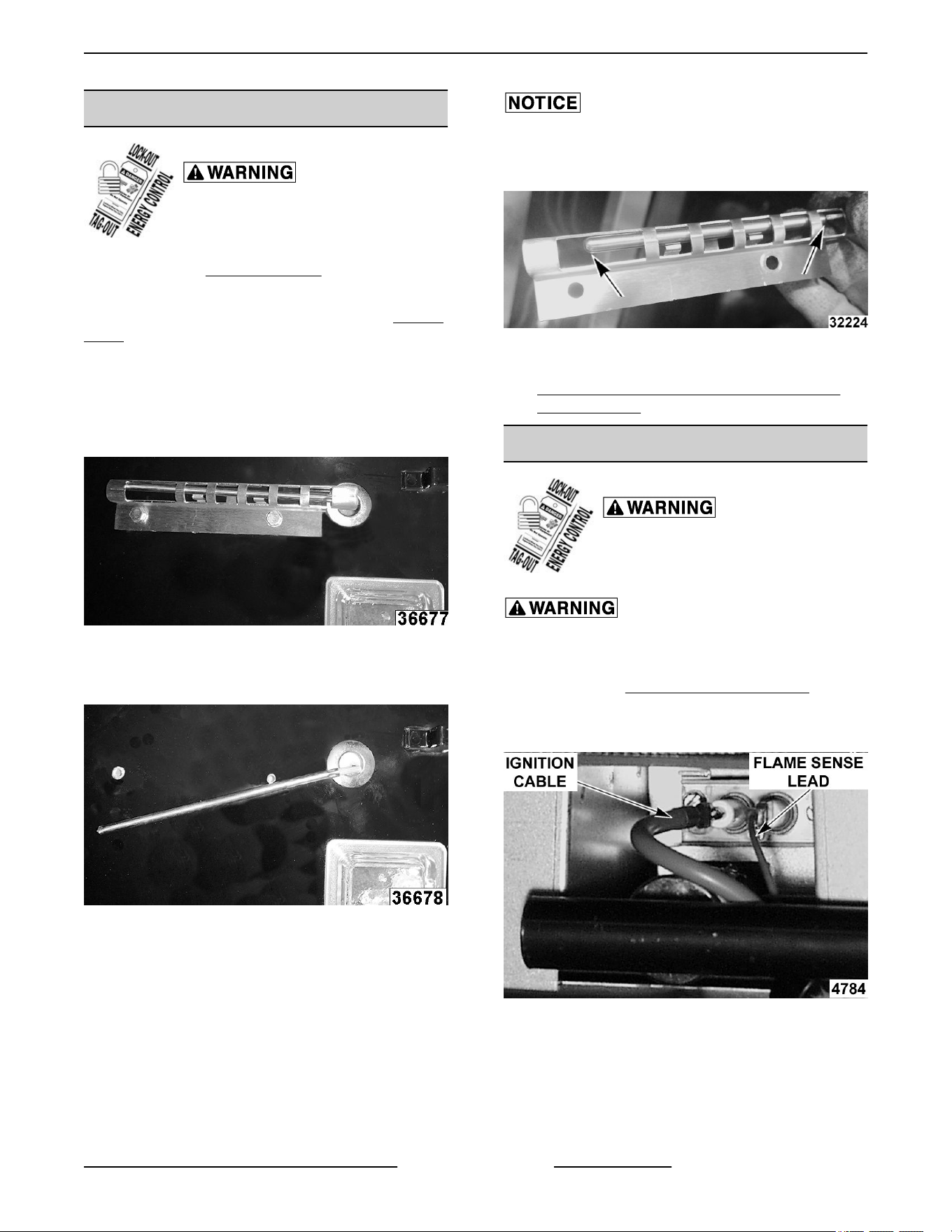
1. Remove the BOTTOM FRONT COVER.
2. Disconnect the ignition cable and the flame
sense lead wire.
Fig. 10
3.
Remove the bolts securing the gas manifold to
the oven and place the manifold to the side.
VC4G & VC6G SERIES FULL SIZE CONVECTION OVENS - REMOVAL AND REPLACEMENT OF PARTS
Page 9 of 86 F24682 Rev. J (0825)
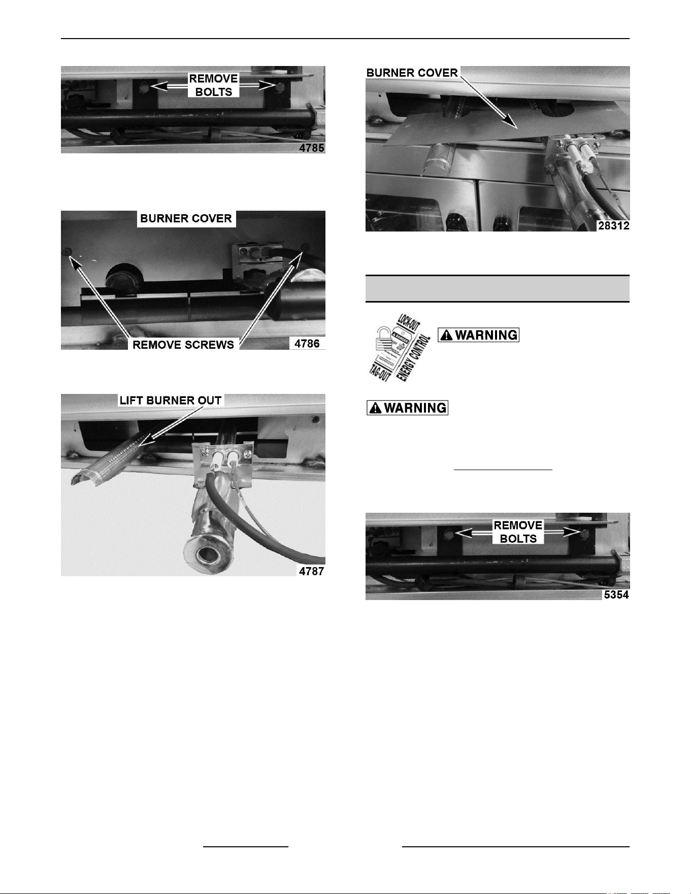
Fig. 11
4. Remove the screws securing the burner cover
then lift out.
Fig. 12
5.
Grasp the burner and lift out.
Fig. 13
6.
Reverse procedure to install the replacement
burner.
NOTE: Ensure that burner positioning bracket (U
shaped end) is inserted into slot at the rear of the
burner chamber.
NOTE: When installing current production burner
covers:
• Lay cover flat over burner with openings
aligned behind ignitor.
• Push burner into unit and flip cover 90° up
and align mounting holes.
Fig. 14
7. Check for proper operation.
GAS ORIFICE
Disconnect the electrical power to
the machine and follow lockout /
tagout procedures.
SHUT OFF THE GAS BEFORE SERVICING THE
UNIT.
1.
Remove the
Bottom Front Cover.
2.
Remove the bolts securing the gas manifold to
the oven and place the manifold to the side.
Fig. 15
3.
Remove the gas orifice from the spud on the
manifold and replace with the correct orifice for
the given altitude.
VC4G & VC6G SERIES FULL SIZE CONVECTION OVENS - REMOVAL AND REPLACEMENT OF PARTS
F24682 Rev. J (0825) Page 10 of 86
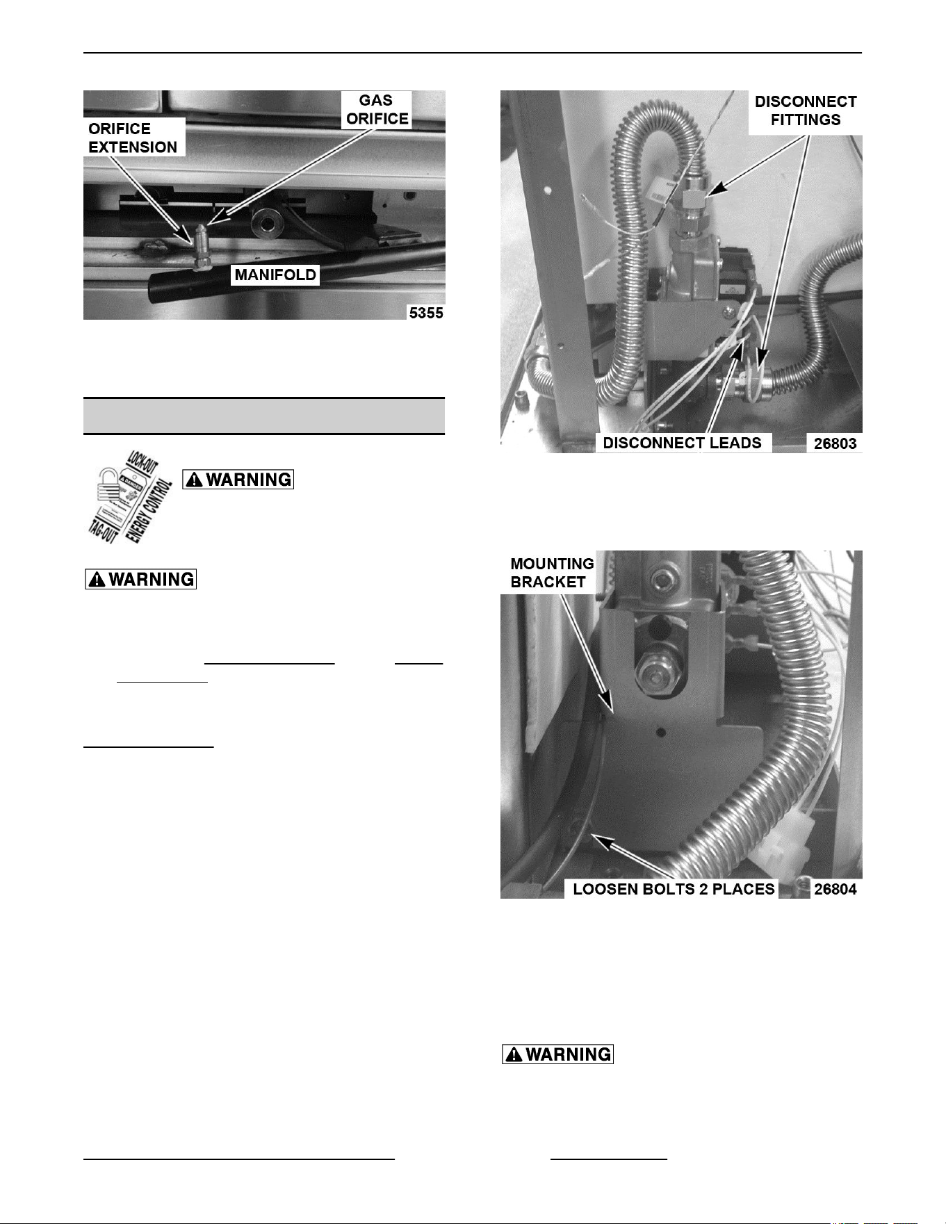
Fig. 16
4. Reverse procedure to install and check for proper
operation.
GAS SOLENOID VALVE
Disconnect the electrical power to
the machine and follow lockout /
tagout procedures.
SHUT OFF THE GAS BEFORE SERVICING THE
UNIT.
1. Remove the CONTROL PANEL and the RIGHT
SIDE PANEL.
NOTE: if right side panel is not accessible, this
component can be serviced by removing the
CONTROL PANEL.
2. Disconnect the lead wires.
3. Disconnect the compression fittings to the valve.
Fig. 17
4. Loosen the bolts securing the valve and bracket
assembly then remove the screws securing the
valve to the bracket.
Fig. 18
5. Reverse
the procedure to install the replacement
gas valve.
NOTE: Clean the pipe threads and apply pipe joint
compound to threads. Any pipe joint compound used,
must be resistant to the action of propane gases.
All gas joints disturbed during servicing must be
checked for leaks. Check with a soap and water
solution (bubbles). Do not use an open flame.
VC4G & VC6G SERIES FULL SIZE CONVECTION OVENS - REMOVAL AND REPLACEMENT OF PARTS
Page 11 of 86 F24682 Rev. J (0825)
6. Verify gas pressure as outlined under GAS
VALVE PRESSURE CHECK (for units after
February 2015) and check for proper operation.
IGNITION CONTROL MODULE
Disconnect the electrical power to
the machine and follow lockout /
tagout procedures.
SHUT OFF THE GAS BEFORE SERVICING THE
UNIT.
1.
Remove the
Right Side Panel.
NOTE: If right side panel is not accessible, this
component can be serviced by removing the Control
Panel.
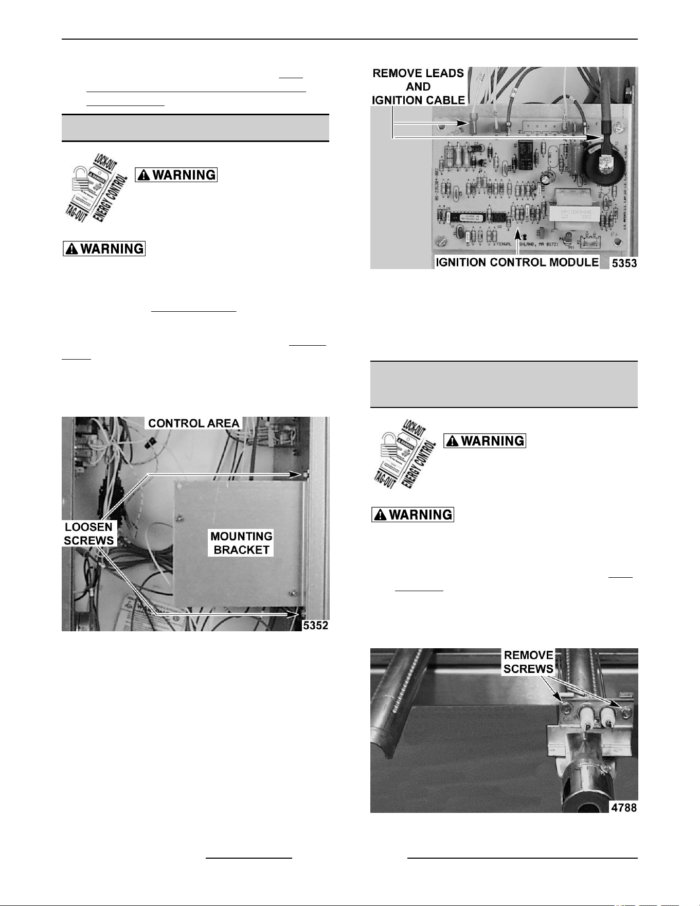
2.
Loosen the screws securing the mounting
bracket to the component panel and remove the
bracket.
Fig. 19
NOTE: When replacing ignition cable, order service
kit which includes ignition cable and insulation cap for
the coil.
3. Disconnect the lead wires and igniter cable from
the ignition module board.
Fig. 20
4. Remove the ignition module board from the
mounting bracket.
5. Reverse the procedure to install the replacement
ignition module board.
SPARK IGNITER AND FLAME
SENSE
Disconnect the electrical power to
the machine and follow lockout /
tagout procedures.
SHUT OFF THE GAS BEFORE SERVICING THE
UNIT.
1. Remove the gas burner as outlined under GAS
BURNER.
2. Remove the screws securing the ignitor and
flame sense to burner then remove the
assembly.
Fig. 21
VC4G & VC6G SERIES FULL SIZE CONVECTION OVENS - REMOVAL AND REPLACEMENT OF PARTS
F24682 Rev. J (0825) Page 12 of 86
3. Reverse the procedure to install the assembly
and check for proper operation.
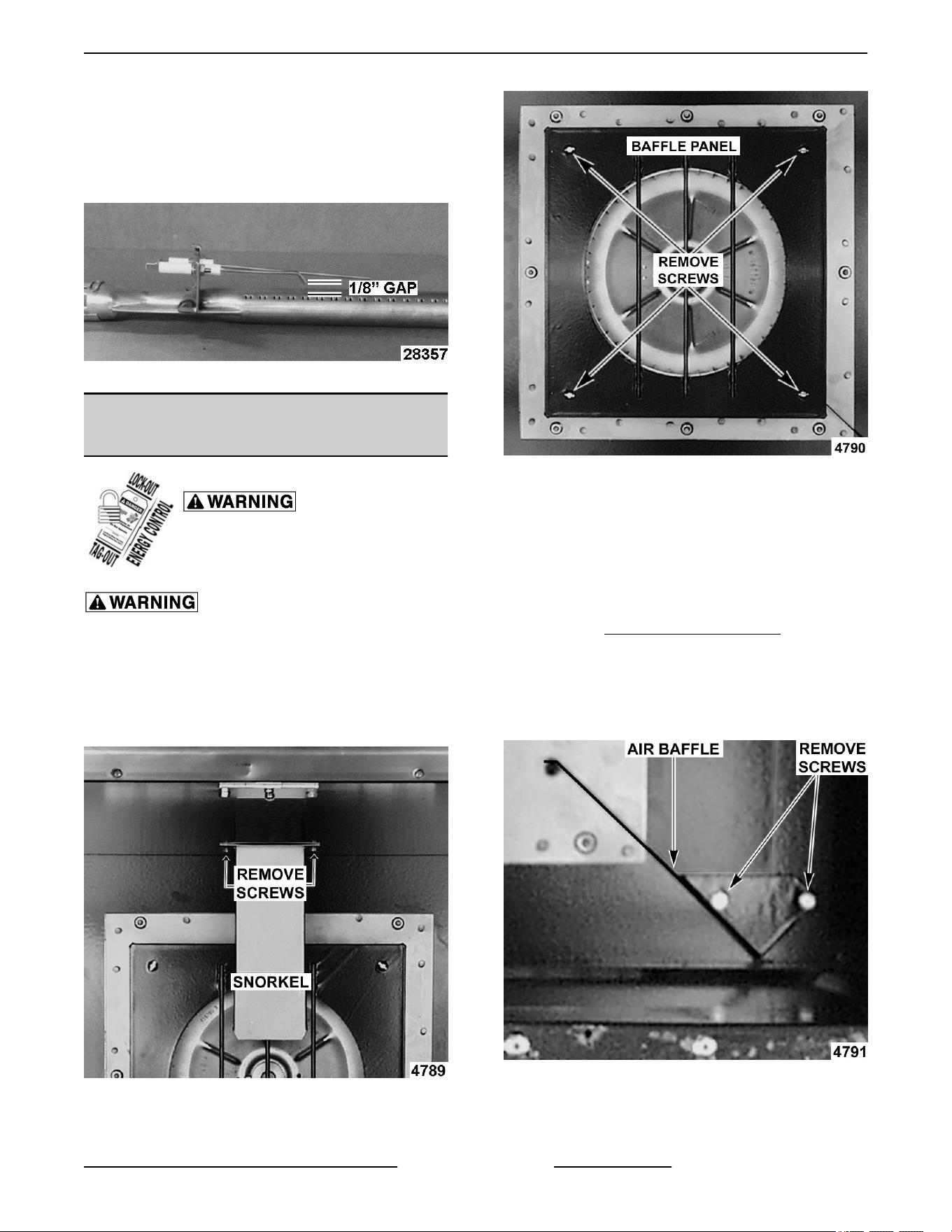
NOTE: Check to ensure the spark gap distance is
approximately
1/8". If the gap appears to be excessive
or poor sparking is occurring then adjust.
Fig. 22
BLOWER AND MOTOR Ending at
Serial Number 481913935
Disconnect the electrical power to
the machine and follow lockout /
tagout procedures.
SHUT OFF THE GAS BEFORE SERVICING THE
UNIT.
1.
Take out the racks and rack supports.
2. Remove screws securing the “snorkel” and
remove the snorkel.
Fig. 23
3.
Remove screws securing baffle panel and
remove the panel.
Fig. 24
4. If replacing:
A. Blower Only - Loosen set screws on blower
hub and using a bearing puller, remove
blower from motor shaft.
1) Reverse procedure to install and adjust
blower position as outlined under
BLOWER ADJUSTMENT.
B. Motor - perform step 4A and continue
procedure.
5. Remove the screws securing the air baffle to the
rear wall at the lower right hand corner.
Fig. 25
6. Remove
the nuts that secure the motor mounting
plate to the rear wall.
VC4G & VC6G SERIES FULL SIZE CONVECTION OVENS - REMOVAL AND REPLACEMENT OF PARTS
Page 13 of 86 F24682 Rev. J (0825)
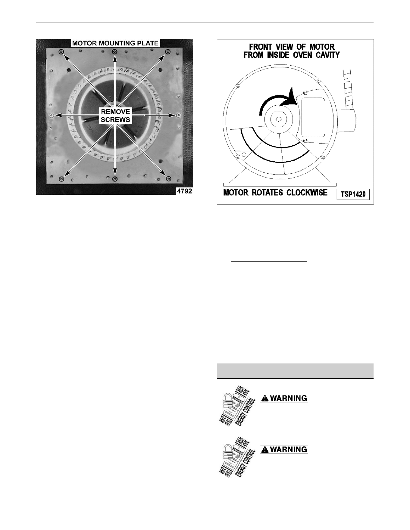
Fig. 26
7. Place a piece of cardboard on the bottom of the
oven cavity to protect its surface from any
damage during motor assembly removal.
8. Pull the motor assembly into the oven cavity and
place it on the cardboard.
9. Remove the junction box cover from the motor,
disconnect lead wires and remove the conduit.
10. Remove motor mounting bolts and flat washers
then lift the motor from the mounting plate.
11. Position the replacement motor on the motor
mounting plate and install mounting bolts and
washers. Hand tighten mounting bolts only.
12. Reconnect lead wires at the motor, replace
conduit and junction box cover.
NOTE: Check data plate on motor for wiring
schematic. The motor must rotate clockwise when
viewed from the shaft end.
Fig. 27
13. Slide blower onto motor shaft until hub is flush
with end of shaft then tighten set screws.
14. Adjust motor position until blower is parallel to
motor mounting plate as outlined under
BLOWER ADJUSTMENT.
15. Position motor mounting plate on the rear wall
and secure with nuts and washers.
16. Replace the baffle panel and “snorkel”.
17. Replace the air baffle on the rear wall at the lower
right hand corner.
18. Remove cardboard from the bottom of the oven
cavity.
19. Install rack guides and racks.
20. Check oven for proper operation.
BLOWER AND MOTOR
Disconnect the electrical power to
the machine and follow lockout /
tagout procedures.
Shut off the gas before servicing the
unit and follow lockout / tagout
procedures.
1. Remove RIGHT SIDE PANEL(S).
VC4G & VC6G SERIES FULL SIZE CONVECTION OVENS - REMOVAL AND REPLACEMENT OF PARTS
F24682 Rev. J (0825) Page 14 of 86
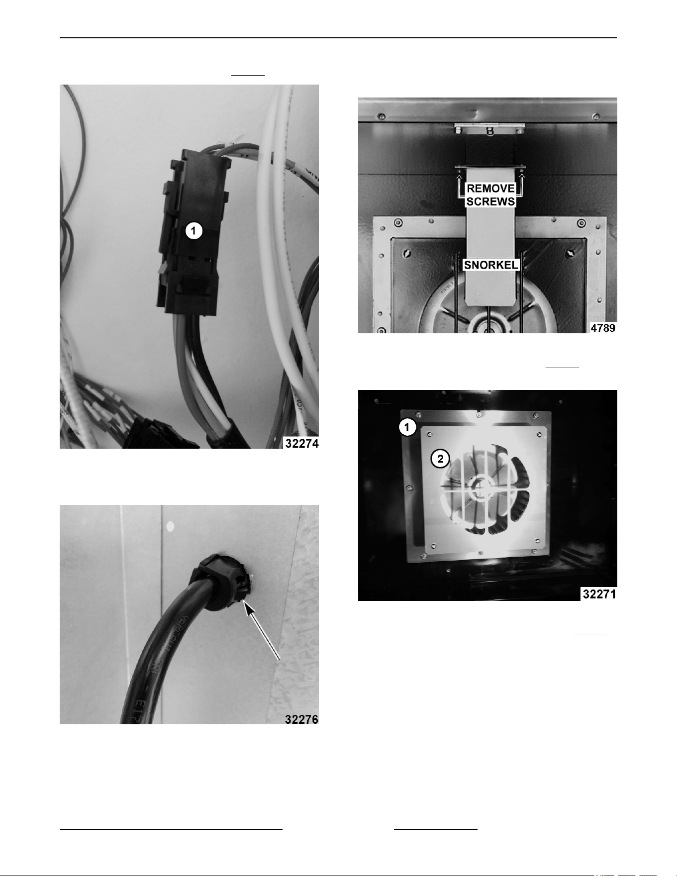
2. Disconnect motor harness (1, Fig. 28).
Fig. 28
3. Pinch cord grip together to remove from rear
panel.
Fig. 29
4.
Push motor wiring harness/cord out hole in rear
panel.
5. Remove racks.
6. Remove screws securing "snorkel" and remove
snorkel.
Fig. 30
7. Remove blower baffle screws (2, Fig. 31) if
applicable.
Fig. 31
8.
Remove motor mounting plate nuts (1,
Fig. 31).
9.
Place a piece of cardboard on bottom of oven
cavity to protect its surface from any damage
during motor assembly removal.
10. Pull motor assembly into oven cavity and place
on cardboard.
11. Remove blower wheel from motor shaft.
12. Remove motor mounting bolts and washers and
lift motor off mounting plate.
VC4G & VC6G SERIES FULL SIZE CONVECTION OVENS - REMOVAL AND REPLACEMENT OF PARTS
Page 15 of 86 F24682 Rev. J (0825)
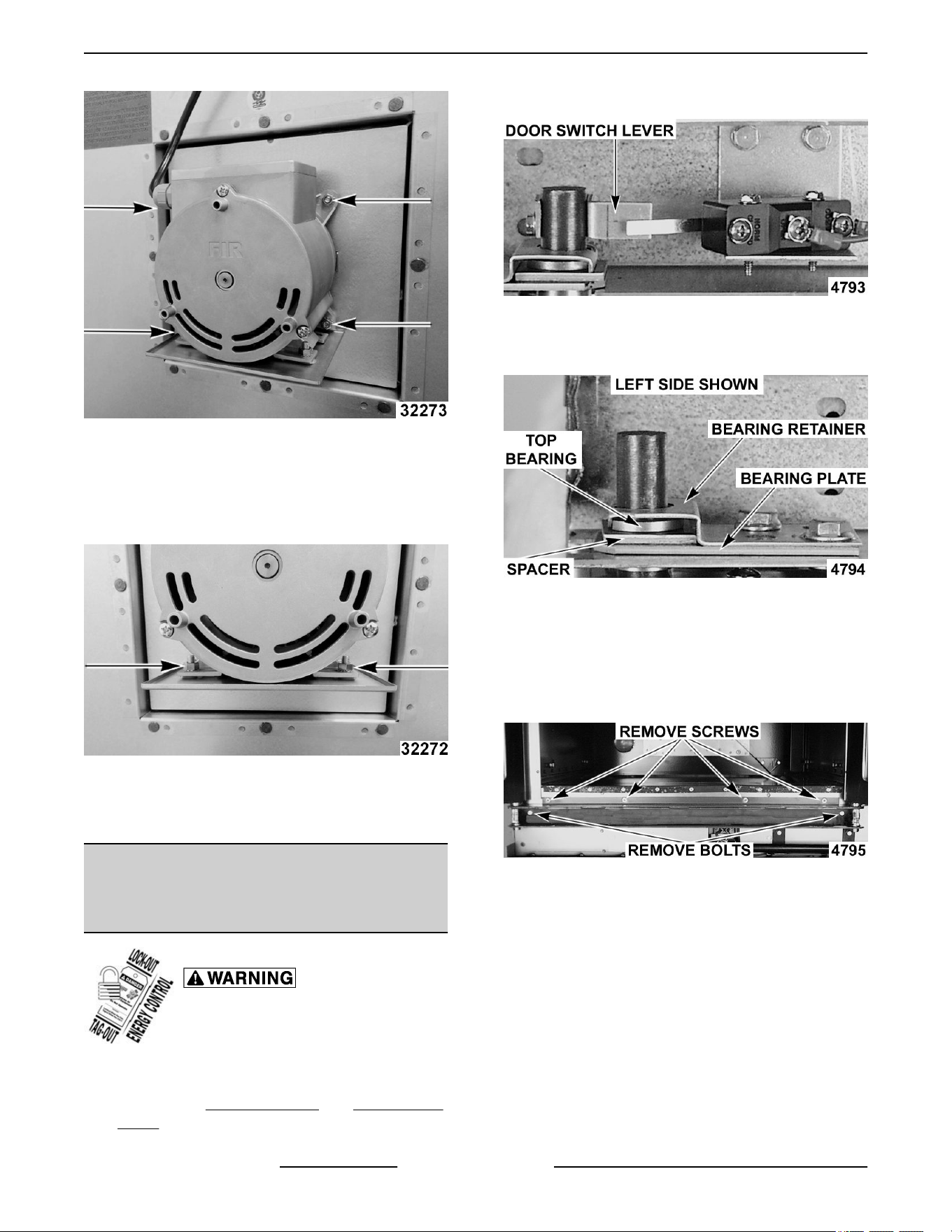
Fig. 32
NOTE: Motor graphics are shown with motor
installed.
13. Remove drip pan from motor and install onto
replacement motor.
Fig. 33
14.
Reverse procedure to install.
15. Verify operation.
OVEN DOORS (SIMULTANEOUS
DOORS) Ending at Serial Number
481907145
Disconnect the electrical power to
the machine and follow lockout /
tagout procedures.
Assembly Removal
1.
Remove the
Top Front Cover and Bottom Front
Cover.
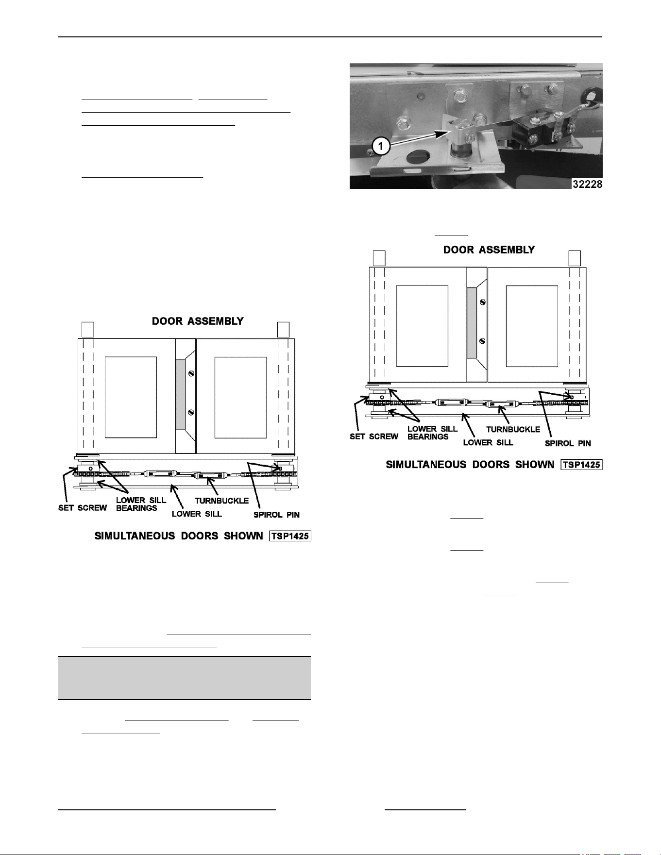
2. Remove the door switch lever.
Fig. 34
3. Remove the top bearing retainers and top
bearings.
Fig. 35
4.
Remove the lower door seal strip to expose the
mounting screws of the door assembly.
A. Remove the two (2) lower sill bolts by the
lower door shaft and the four (4) counter-
sunk screws from the lower sill.
Fig. 36
NOTE: The door assembly is heavy and will drop
down
once the last screw is removed. If removing door
assembly with-out assistance, use caution.
5. Lift up on the door assembly and swing the right
side out then move the assembly to the left to
clear the slots in the upper door sill.
6. Lay the door assembly on a flat cushioned
surface for disassembly.
VC4G & VC6G SERIES FULL SIZE CONVECTION OVENS - REMOVAL AND REPLACEMENT OF PARTS
F24682 Rev. J (0825) Page 16 of 86
7. Reverse procedure to install door assembly and
check for proper adjustment as outlined under
DOOR ADJUSTMENT , DOOR CHAIN
ADJUSTMENT (SIMULTANEOUS DOORS) and
DOOR SWITCH ADJUSTMENT.
Disassembly
1.
Remove the door assembly as outlined in
"ASSEMBLY REMOVAL".
2.
Remove the door chain by loosening one of the
turnbuckles.
3. Loosen the set screw on the sprocket of door
being replaced.
4. Drive out the Spirol pin from the sprocket of door
being replaced.
5. Remove the door from lower sill bearings and
sprocket.
Fig. 37
A. Door assembly parts are now accessible for
inspection and/or replacement if necessary.
6. Reverse procedure to re-assemble the door
assembly parts and check for proper adjustment
as outlined under DOOR CHAIN ADJUSTMENT
(SIMULTANEOUS DOORS).
OVEN DOORS (SIMULTANEOUS
DOORS)
1. Remove TOP FRONT COVER and BOTTOM
FRONT COVER.
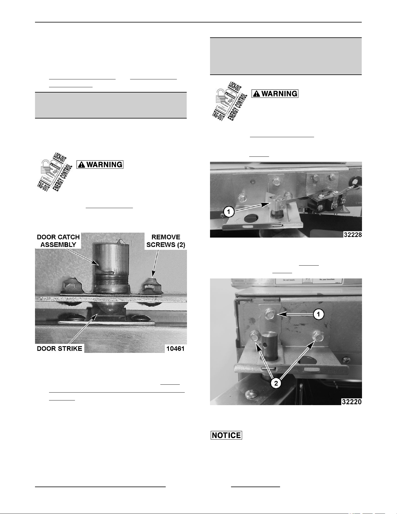
2.
Remove door switch lever.
Fig. 38
3. Remove door chain by loosening one of the
turnbuckles (Fig. 39).
Fig. 39
4.
Loosen the set screw on the sprocket of door
being replaced (
Fig. 39).
5. Drive
out the spiral pin from the sprocket of door
being replaced (
Fig. 39).
6.
While supporting door, remove hex head bolts
holding upper bearing retainer (1,
Fig. 40) and
upper shaft bracket (2, Fig. 40).
VC4G & VC6G SERIES FULL SIZE CONVECTION OVENS - REMOVAL AND REPLACEMENT OF PARTS
Page 17 of 86 F24682 Rev. J (0825)
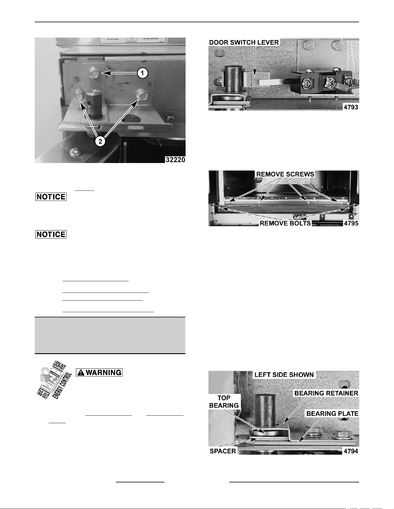
Fig. 40
7. Remove door(s) from lower sill bearings and
sprocket Fig. 39.
Lay door on flat protective surface to service.
8. Reverse procedure to install.
Verify spacers are reassembled as found when
removed.
9. Perform door adjustments.
A. DOOR ADJUSTMENT .
B. DOOR CHAIN ADJUSTMENT
(SIMULTANEOUS DOORS) .
C. DOOR SWITCH ADJUSTMENT .
OVEN DOORS AND BEARINGS
(INDEPENDENT DOORS) Ending at
Serial Number 481907145
Disconnect the electrical power to
the machine and follow lockout /
tagout procedures.
1. Remove the Top Front Cover and Bottom Front
Cover.
2. Remove the door switch lever.
Fig. 41
3. Remove the lower door seal strip to expose the
mounting screws of the door assembly.
4. Remove the two (2) lower sill bolts by the lower
door shaft and the four (4) counter-sunk screws
from the lower sill.
Fig. 42
NOTE: The door assembly is heavy and will drop
down
once the last screw is removed. If removing door
assembly with-out assistance, the ignition cable,
flame sense lead and gas manifold should also be
removed to avoid damage to these components.
5. Tilt the top of the door slightly forward and lift the
door up until the bottom of the door shaft clears
the opening in the sill.
6. Lay the door flat to prevent damage.
7. The top and bottom bearings are now accessible
for inspection and/or replacement if needed.
A. If bearings are OK, proceed to step 8.
B. If replacing the top bearing, remove the top
bearing retainer and top bearing.
Fig. 43
VC4G & VC6G SERIES FULL SIZE CONVECTION OVENS - REMOVAL AND REPLACEMENT OF PARTS
F24682 Rev. J (0825) Page 18 of 86
C. If replacing the bottom bearing, remove it
from
the door shaft or the lower sill opening.
8. Reverse procedure to install door assembly and
check for proper adjustment as outlined under
DOOR ADJUSTMENT and DOOR SWITCH
ADJUSTMENT.
DOOR CATCH BALL ASSEMBLY
(INDEPENDENT DOORS)
NOTE: For units with serial number starting with 48
made before 8/13/07 and serial number starting with
54 made before 8/27/07.
Disconnect the electrical power to
the machine and follow lockout /
tagout procedures.
1.
Remove the
FRONT COVER.
2.
Remove the screws that secure the door catch
assembly.
Fig. 44
3. Reverse procedure to install.
4. Adjust the ball catch as outlined under DOOR
CATCH BALL ADJUSTMENT (INDEPENDENT
DOORS).
OVEN DOORS (INDEPENDENT
DOORS) Starting at Serial Number
481907146
Disconnect the electrical power to
the machine and follow lockout /
tagout procedures.
1.
Remove
TOP FRONT COVER.
2.
If servicing right side door, remove door switch
lever (1,
Fig. 45).
Fig. 45
3. While supporting door, remove hex bolts holding
upper bearing retainer (1, Fig. 46 ) and upper
shaft bracket (2, Fig. 46).
Fig. 46
4.
Lift door off lower shaft bracket.
Lay door on flat protective surface to service.
5.
Reverse procedure to install.
VC4G & VC6G SERIES FULL SIZE CONVECTION OVENS - REMOVAL AND REPLACEMENT OF PARTS
Page 19 of 86 F24682 Rev. J (0825)
6. Perform
door switch adjustment if servicing right
side door.
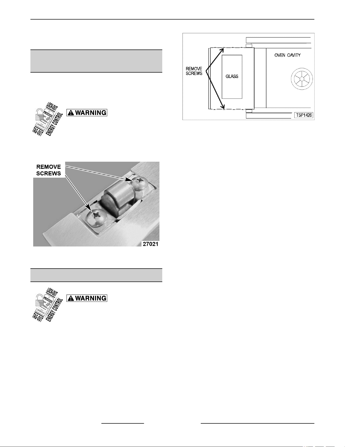
ROLLER LATCH ASSEMBLY
(INDEPENDENT DOORS)
NOTE: For units with serial number starting with 48
made
after 8/12/07 and serial number starting with 54
made after 8/26/07.
Disconnect the electrical power to
the machine and follow lockout /
tagout procedures.
1.
Remove the screws that attach roller latch
assembly to door.
Fig. 47
2. Reverse procedure to install.
DOOR WINDOW
Disconnect the electrical power to
the machine and follow lockout /
tagout procedures.
1. Remove the screws at the top and bottom of
door.
Fig. 48
2. Independent doors:
A. Remove the door handle then remove the
outer door panel.
B. Lift out the inner door panel and window
assembly.
NOTE: Left door only - remove door seal from the
inside edge of the door.
3. Simultaneous doors:
A. If replacing window on the left door, remove
the handle from the front of the door then
remove door seal from the inside edge of the
door.
1) Lift out the inner door panel and
window assembly.
2) If replacing window on the right door,
remove the screws along the inside
edge (if applicable) of the door then
remove the inner door panel and
window assembly.
4. Remove the screws securing the window “tabs”
to the door bracket and lift the window assembly
out from the door frame.
VC4G & VC6G SERIES FULL SIZE CONVECTION OVENS - REMOVAL AND REPLACEMENT OF PARTS
F24682 Rev. J (0825) Page 20 of 86
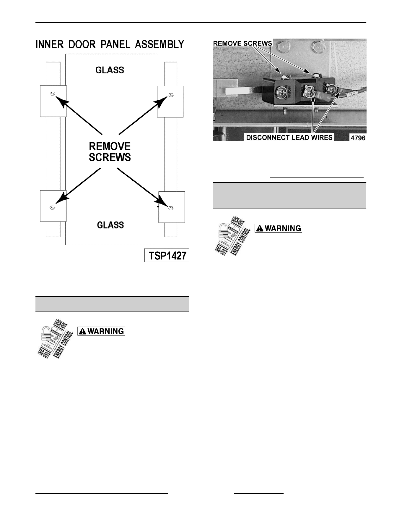
Fig. 49
5. Reverse procedure to install the replacement
window.
DOOR SWITCH
Disconnect the electrical power to
the machine and follow lockout /
tagout procedures.
1.
Remove the
Top Front Cover.
2.
Disconnect the lead wires to the door switch.
3. Remove the switch.
Fig. 50
4. Reverse procedure to install the replacement
switch and check for proper adjustment as
outlined under DOOR SWITCH ADJUSTMENT.
MECHANICAL KX THERMOSTAT
(VC4GS/6GS)
Disconnect the electrical power to
the machine and follow lockout /
tagout procedures.
1. Remove the racks and right rack support.
2. Remove the thermostat knob and mounting
screws from the control panel and then remove
the control panel.
3. Remove the probe guard from the oven cavity
wall.
NOTE: When installing, the probe should not extend
beyond the probe guard.
4. Remove the thermostat bulb from the oven cavity
by pushing it through the oven wall and into the
control panel area.
NOTE: The hole in the oven cavity wall does not line
up straight with the oven cavity outer shell, therefore
the probe must be removed at an angle.
5. Reverse the procedure to install.
6. Adjust the thermostat as outlined under
MECHANICAL THERMOSTAT CALIBRATION
(VC4GS/6GS).
VC4G & VC6G SERIES FULL SIZE CONVECTION OVENS - REMOVAL AND REPLACEMENT OF PARTS
Page 21 of 86 F24682 Rev. J (0825)
HIGH LIMIT THERMOSTAT
Disconnect the electrical power to
the machine and follow lockout /
tagout procedures.
1.
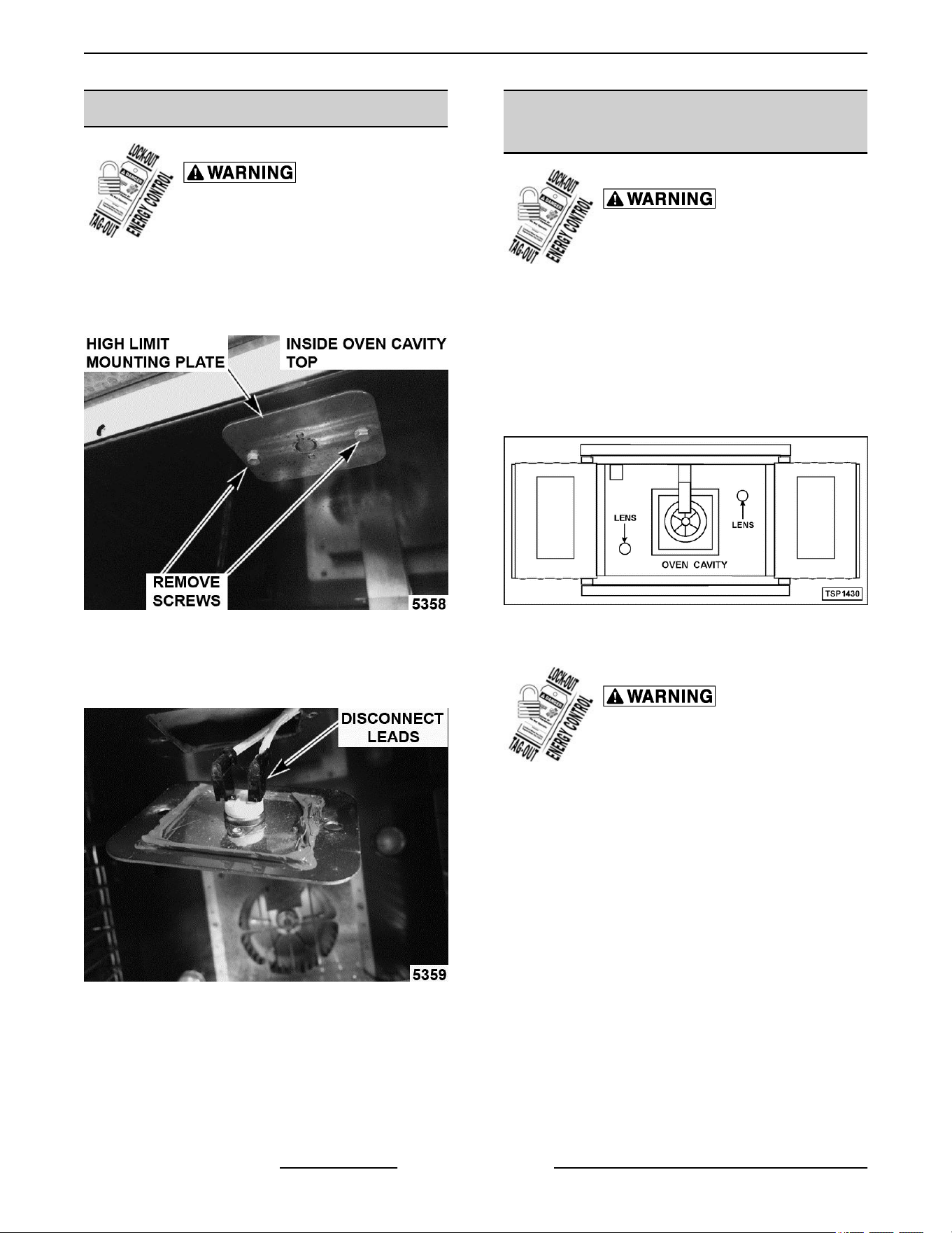
Take out racks from the oven.
2. Remove the high limit thermostat cover/mounting
plate from inside the oven cavity at the top.
Fig. 51
3. Disconnect lead wires from high limit thermostat
then remove high limit thermostat from cover/
mounting plate.
Fig. 52
NOTE: Remove the old RTV from the cover and
mating
surfaces inside the oven cavity and apply new
RTV before installing.
4. Reverse procedure to install.
INTERIOR LIGHTS (Rear Mounted,
Round)
Disconnect the electrical power to
the machine and follow lockout /
tagout procedures.
Lamp
1.
Remove racks.
2. Unscrew glass lens for the light being replaced
then unscrew bulb.
NOTE: Use a cloth when handling bulb so you do not
leave fingerprints on bulb.
Fig. 53
3. Replace bulb then reverse procedure to install.
Disconnect the electrical power to
the machine and follow lockout /
tagout procedures.
Lamp Assembly
1. Remove lens and bulb.
2. Remove springs from retaining tabs (2 places) on
the socket.
VC4G & VC6G SERIES FULL SIZE CONVECTION OVENS - REMOVAL AND REPLACEMENT OF PARTS
F24682 Rev. J (0825) Page 22 of 86
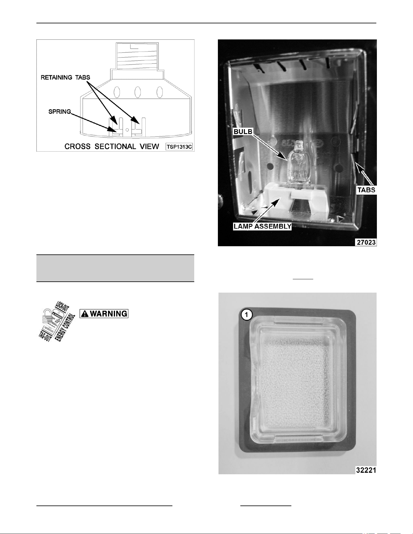
Fig. 54
3. Depress retaining tabs and pull socket out from
the oven, far enough to disconnect lead wires.
4. Remove socket from the oven.
5. Attach lead wires to the replacement socket.
6. Insert socket into the hole in oven and push until
socket is held in place by retaining tabs.
7. Install light bulb and lens.
8. Check for proper operation.
INTERIOR LIGHTS (Side Mounted,
Square)
Bulb Replacement
Disconnect the electrical power to
the machine and follow lockout /
tagout procedures.
1. Remove racks and right-side hand rack guide.
2. Pull lamp cover off.
3. Grasp lamp using a clean cloth and remove from
lamp assembly.
Fig. 55
4.
Reverse procedure to install new bulb.
NOTE: Verify gasket (1,
Fig. 56)
is flat on lamp cover
and not damaged.
Fig. 56
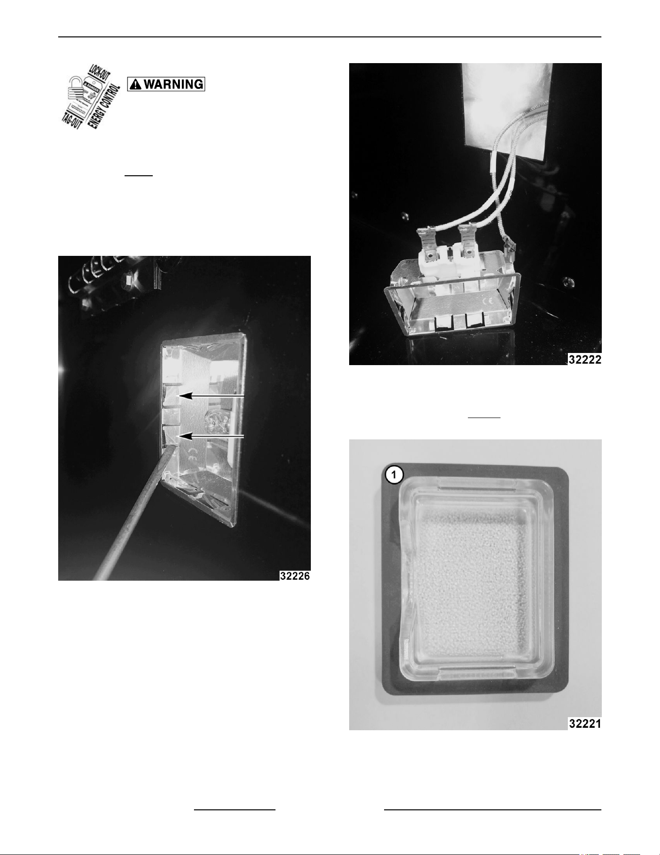
Lamp Assembly Replacement
VC4G & VC6G SERIES FULL SIZE CONVECTION OVENS - REMOVAL AND REPLACEMENT OF PARTS
Page 23 of 86 F24682 Rev. J (0825)
Disconnect the electrical power to
the machine and follow lockout /
tagout procedures.
1.
Remove racks.
2. Remove
BULB if reusing.
3.
Lift right side rack guide off oven cavity.
4. Pull lamp cover off from the top or bottom.
5. Insert narrow blade screwdriver into tab and
bend out to release. Repeat with second tab.
Fig. 57
6. Pull lamp housing out of oven cavity.
7. Disconnect wires.
Fig. 58
8. Reverse procedure to install.
NOTE: Verify gasket (1, Fig. 59) is flat on lamp cover
and not damaged.
Fig. 59
VC4G & VC6G SERIES FULL SIZE CONVECTION OVENS - REMOVAL AND REPLACEMENT OF PARTS
F24682 Rev. J (0825) Page 24 of 86
COOLING FAN
Disconnect the electrical power to
the machine and follow lockout /
tagout procedures.
1.
Remove the
Right Side Panel.
NOTE: If right side panel is not accessible, this
component can be serviced by removing the Control
Panel.
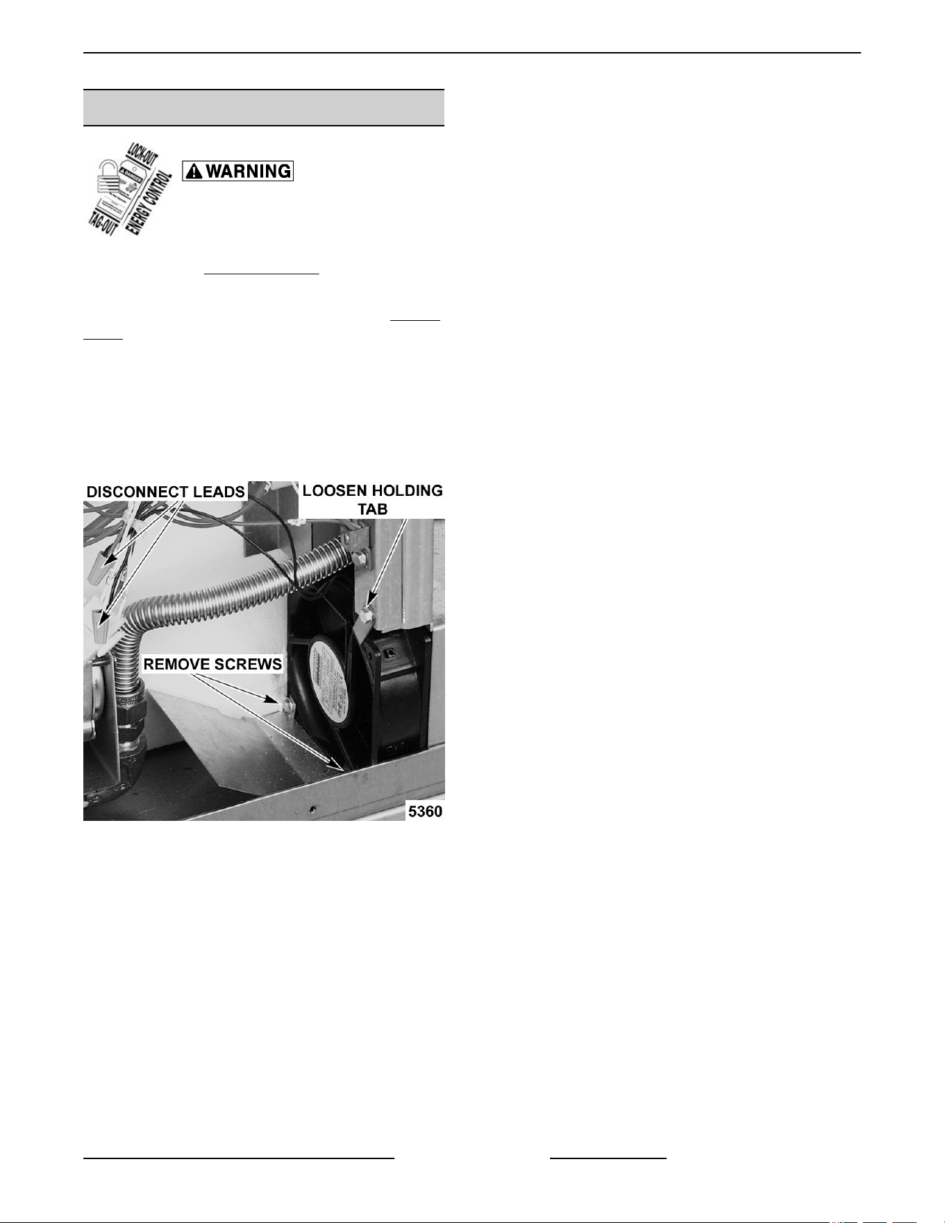
Disconnect the lead wires to the fan motor by
removing wire nuts.
2.
Remove the screws securing the air deflector to
the fan then loosen the tab screw holding the fan
to the component panel. Rotate the tab so that
the fan will clear and remove the fan.
Fig. 60
3. Reverse the procedure to install the replacement
fan and check for proper operation.
NOTE: The fan must be installed so air is pulled from
the rear of the oven and blown into the control area.
The arrow on the fan body indicates “air flow” direction
and should be pointing toward the controls.
NOTE: Ensure fan is seated “squarely” against the air
tube and the oven bottom.
NOTE: The air deflector should be angled upwards
at approximately 30 degrees to properly direct the air
flow.
VC4G & VC6G SERIES FULL SIZE CONVECTION OVENS - REMOVAL AND REPLACEMENT OF PARTS
Page 25 of 86 F24682 Rev. J (0825)
SERVICE PROCEDURES AND ADJUSTMENTS
Certain procedures in this section require electrical test or measurements while power is
applied
to the machine. Exercise extreme caution at all times and follow Arc Flash procedures.
If test points are not easily accessible, disconnect power and follow Lockout/Tagout
procedures, attach test equipment and reapply power to test.
SOLID STATE TEMPERATURE
CONTROL CALIBRATION
1. Place a thermocouple in geometric center of
oven cavity.
2.
Set ON-OFF-COOL DOWN switch to ON.
3. Set temperature control dial to 350°F.
4. Allow oven temperature to stabilize (normally 3
cycles).
5. Record temperature at which Heat lamp goes
OFF and comes ON for at least two complete
heating cycles.
6. Calculate differential by subtracting temperature
indicated when lamp goes out from temperature
indicated when lamp comes on.
Differential = Heat lamp OFF - Heat lamp ON
Example: 360° (lamp off) - 340° (lamp on) =
20°
A. Calculated differential should be less than
20°F.
1) If differential is less than 20°F,
temperature control circuit is
functioning properly.
a. Proceed to
Step 7.
2)
If the differential is more than 20°F:
a. Check the temperature probe as
outlined under
TEMPERATURE
PROBE TEST.
b.
If probe is functioning properly
then temperature control is
malfunctioning.
a) Install a replacement
temperature control and
check calibration.
7. Calculate average temperature by adding
temperature indicated when lamp goes out to
temperature indicated when lamp comes on and
dividing this answer by 2.
[Temp. (lamp off) + Temp. (lamp on)] ÷ 2 =
Average Temp. Example: (360° + 340°) ÷ 2 =
350°
A. If average temperature is less than 10°F
from dial setting, thermostat is properly
calibrated.
B. If average temperature is more than 10°F
from dial setting, thermostat calibration
must be adjusted.
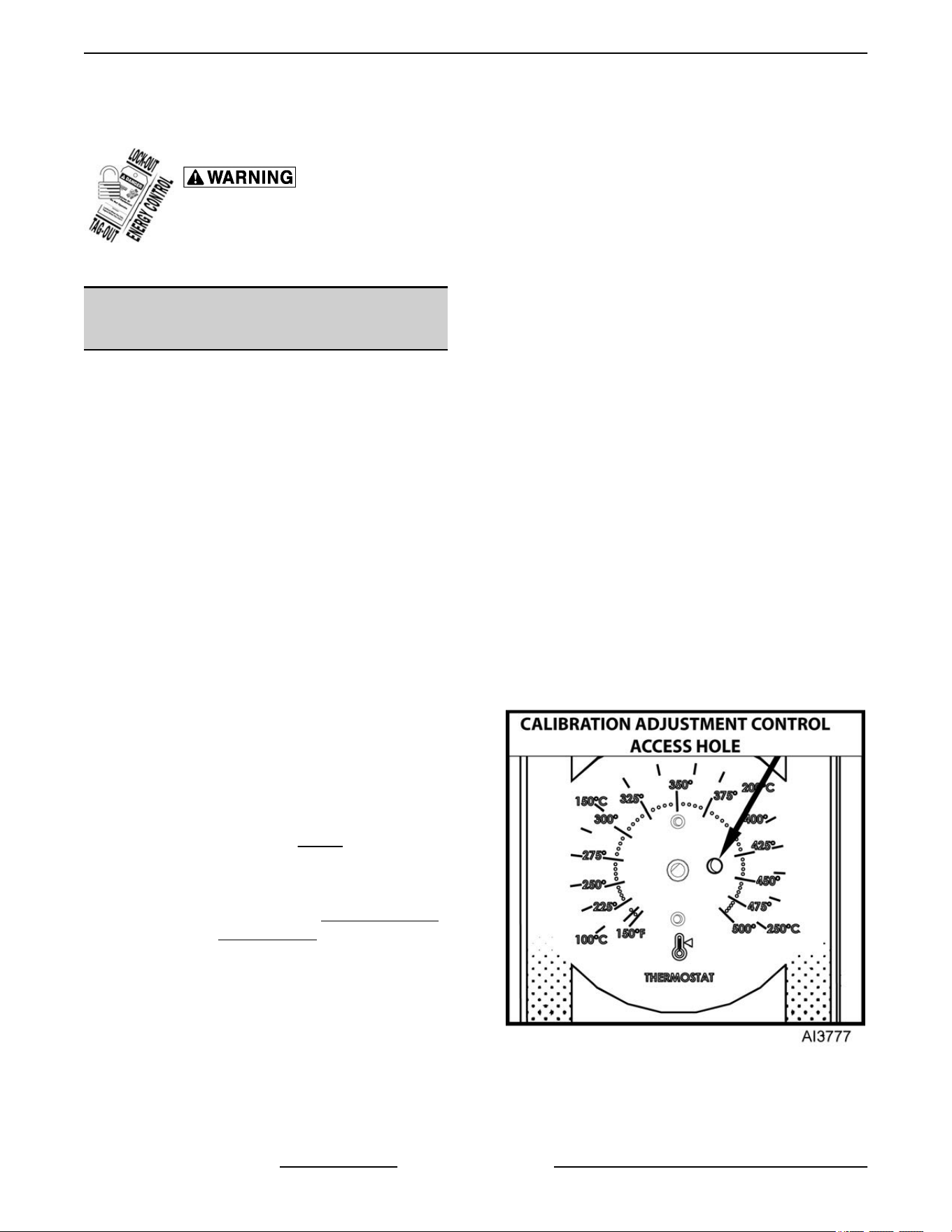
1) Loosen temperature control knob set
screw and remove knob from stem.
2) Access adjustment potentiometer
located at 3 o'clock position.
NOTE: If no access hole exists in overlay, you may
carefully create one.
Fig. 61
a.
Turn clockwise to increase,
counterclockwise to decrease
temperature
VC4G & VC6G SERIES FULL SIZE CONVECTION OVENS - SERVICE PROCEDURES AND ADJUSTMENTS
F24682 Rev. J (0825) Page 26 of 86
b. Repeat average temperature
calculation in Step 7.
NOTE:
Allow oven to cycle at least two times between
adjustments before performing calculation.
a) If average temperature still
differs more than 10°F from
dial setting, adjust
thermostat calibration until
average temperature is
within tolerance.
C. If above adjustment cannot be obtained,
replace temperature control and check
calibration.
MECHANICAL THERMOSTAT
CALIBRATION (VC4GS/6GS)
1. Place a thermocouple in the geometric center of
the oven cavity.
2.
Set the ON-OFF-COOL DOWN switch to ON.
3. Set the thermostat dial to 350°F.
4. Allow the oven temperature to stabilize (normally
3 cycles).
5. Record the temperature when the thermostat
cycles OFF and ON for at least three complete
cycles.
6. Calculate the differential by subtracting the
temperature indicated when heat lamp goes out
from temperature indicated when heat lamp
comes on.
Differential = Heat lamp OFF - Heat lamp ON
Example: 360° (lamp off) - 340° (lamp on) 20°
A. The differential calculated should be less
than 30°F.
1) If the differential is less than 30°F, the
thermostat is functioning properly.
a. Proceed to
Step 7.
2) If
the differential is more than 30°F, the
thermostat is malfunctioning.
a. Install a replacement thermostat
and check calibration.
7. Calculate the average temperature by adding the
temperature indicated when the heat lamp goes
out to the temperature indicated when the heat
lamp comes on and dividing this answer by 2.
[Temp. (lamp off) +Temp. (lamp on)] ÷ 2 =
Average Temp.
Example: 360° 340° ÷ 2 350°
A. If the average temperature is less than 15°F
from the dial setting, the thermostat is
properly calibrated.
B. If the average temperature is more than
15°F of the dial setting, the thermostat
calibration must be adjusted.
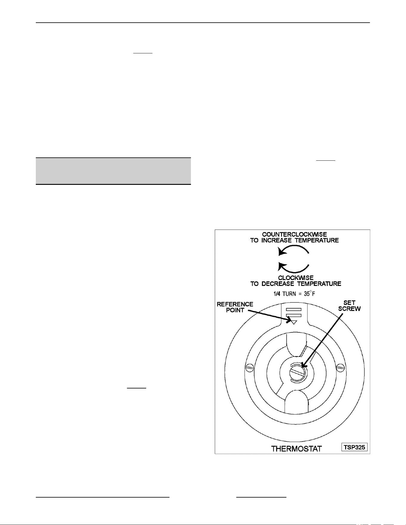
1) Remove the thermostat knob.
2) Hold the thermostat shaft and turn the
inner set screw clockwise to decrease
temperature or counterclockwise to
increase temperature (¼ turn = 35°(F).
8. Replace the knob and repeat
Step 7 until the
average temperature is within tolerance.
NOTE: Allow the oven to cycle at least two times
between adjustments before performing the
calculation.
9.
If the above adjustment can not be obtained,
install a replacement thermostat and check
calibration.
Fig. 62
VC4G & VC6G SERIES FULL SIZE CONVECTION OVENS - SERVICE PROCEDURES AND ADJUSTMENTS
Page 27 of 86 F24682 Rev. J (0825)
SOLID STATE TEMPERATURE
CONTROL TEST
Certain procedures in this section
require electrical test or
measurements while power is
applied to the machine. Exercise
extreme caution at all times and
follow Arc Flash procedures. If test
points are not easily accessible,
disconnect power and follow
Lockout/Tagout procedures, attach
test
equipment and reapply power to
test.
1. Remove the
RIGHT SIDE PANEL.
NOTE: If right side panel is not accessible, this
component can be serviced by removing CONTROL
PANEL.
2.
Place a thermocouple in the geometric center of
the oven cavity.
NOTE: Oven temperature must be below 450°F.
NOTE: If oven is equipped with "Cook and Hold"
option, set to Cook (normal cooking) before
continuing.
3. Set the temperature control to the maximum
setting.
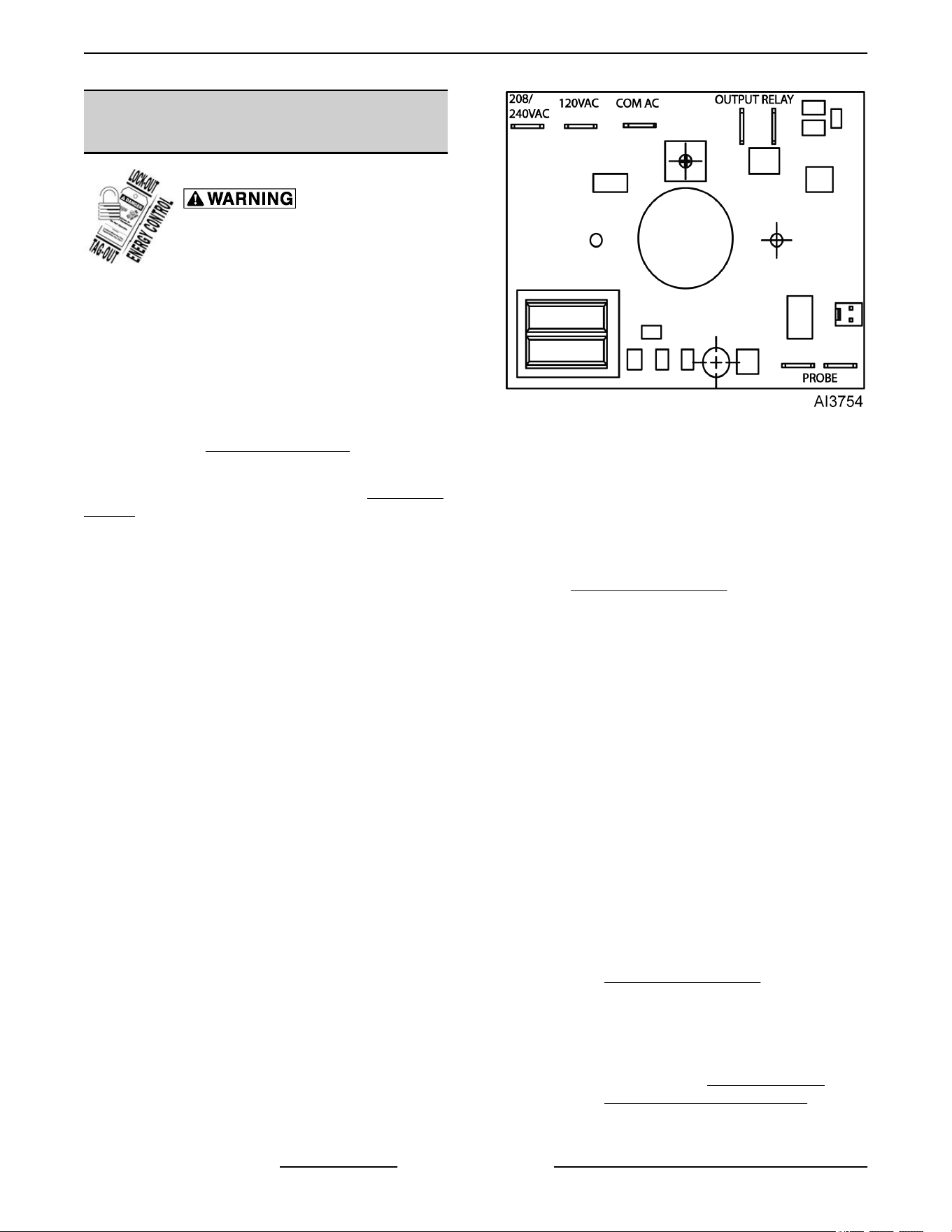
4. Check machine data plate for correct voltage to
oven. Refer to diagram below for proper terminal
locations and voltages before checking the
control. Use the correct terminals for the
corresponding voltage.
5. Turn the power switch to ON.
Fig. 63
6.
Check for proper voltage across terminals COM
AC to 120VAC or COM AC to 208-240VAC for
power to the control.
A. If correct, proceed to step 7.
B. If incorrect, problem is not with the
temperature control. See
TROUBLESHOOTING.
7.
Check relay voltages on the board:
A. For 120VAC controls - check across
OUTPUT RELAY terminal (left side) to
120VAC terminal for input to the internal
relay. Check across OUTPUT RELAY
terminal (right side) to 120 VAC for output
from the internal relay.
B. For 208-240VAC controls - check across
OUTPUT RELAY terminal (left side) to
208-240VAC terminal for input to the
internal relay. Check across OUTPUT
RELAY terminal (right side) to 208-240VAC
for output from the internal relay.
1) If input voltage to the internal relay is
correct, proceed to step 8. If input
voltage to the internal relay is not
present, problem is not with the
temperature control. See
TROUBLESHOOTING.
2) If
output voltage from the internal relay
is correct proceed to step 8. If output
voltage from the internal relay is not
correct, check temperature probe as
outlined under
TEMPERATURE
PROBE TEST (VC4GD/6GD).
8.
Set the temperature control to the minimum
setting.
VC4G & VC6G SERIES FULL SIZE CONVECTION OVENS - SERVICE PROCEDURES AND ADJUSTMENTS
F24682 Rev. J (0825) Page 28 of 86
NOTE: Oven temperature must be above 300°F.
9.
Check for zero (0) volts AC across terminals
OUTPUT RELAY terminal (right side) to 120VAC
or OUTPUT RELAY terminal (right side) to
208-240VAC for no output from the internal relay.
A. If correct, temperature control is functioning
properly.
B. If incorrect, check temperature probe as
outlined under
TEMPERATURE PROBE
TEST (VC4GD/6GD).
1)
If temperature probe is OK:
a. Turn the power switch OFF.
Disconnect the electrical power to
the machine and follow lockout /
tagout procedures.
b.
Replace the temperature control
and check calibration as outlined
under
SOLID STATE
TEMPERATURE CONTROL
CALIBRATION (VC4GD/6GD).
TEMPERATURE PROBE TEST
Disconnect the electrical power to
the machine and follow lockout /
tagout procedures.
NOTE: The temperature probe used in conjunction
with the Solid State Temperature control is an RTD
(resistance temperature detector) of the Thermistor
type. As temperature increases the resistance value
decreases.
1.
Remove the
Right Side Panel.
NOTE: If right side panel is not accessible, this
component can be serviced by removing the Control
Panel.
2.
Place a shielded thermocouple in the geometric
center of the oven cavity and determine the
temperature in the oven cavity.
3. Remove the probe lead wires from the solid state
temperature control.
4. Test the probe with an ohmmeter.
A. If the measured resistance values are inside
the given tolerance then the probe is
functioning properly.
B. If the measured resistance values are
outside the given tolerance then replace the
probe and retest.
1) Check oven for proper operation.
5. Reverse procedure to install.
TEMP (°F)
OHMS* TEMP (°F) OHMS*
77 90,000 360 822
240 4,077 380 656
260 3,016 400 529
280 2,266 425 424
300 1,726 450 334
320 1,332 475 266
340 1,041
(*) Resistance in ohms ± 10%
GAS PRESSURE ADJUSTMENT
(units up to February 2015)
Disconnect the electrical power to
the machine and follow lockout /
tagout procedures.
1.
Turn gas supply off at manual shutoff valve.
2. Remove the
Right Side Panel.
NOTE: If right side panel is not accessible, this
component can be serviced by removing the Control
Panel.
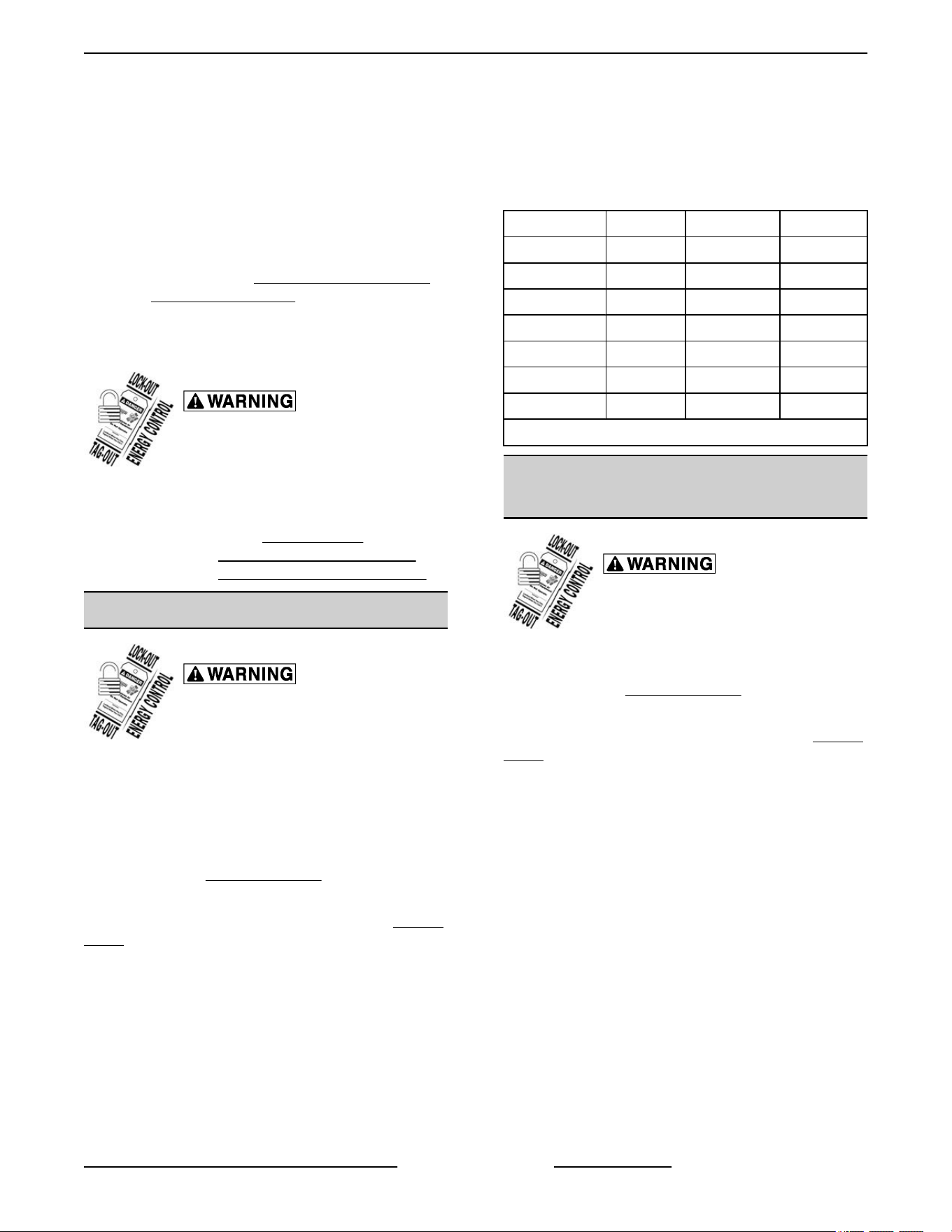
3.
Remove the plug from the manifold pressure
port.
VC4G & VC6G SERIES FULL SIZE CONVECTION OVENS - SERVICE PROCEDURES AND ADJUSTMENTS
Page 29 of 86 F24682 Rev. J (0825)
FIRST GENERATION UNIT SHOWN (Before April
2005)
SECOND GENERATION UNIT SHOWN (After April
2005 thru February 2015)
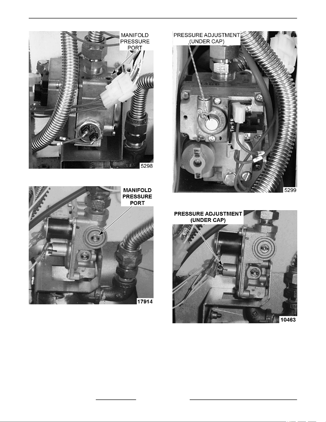
4. Install
hose barb adapter and attach manometer
tube.
FIRST GENERATION UNIT SHOWN (Before April
2005)
SECOND GENERATION UNIT SHOWN (After April
2005 thru February 2015)
5.
Remove adjustment screw cap from the gas
valve and turn gas supply to the oven back on.
6. Plug the unit in and turn the power switch ON.
7. Set the temperature control to its highest setting
and allow burner to ignite.
NOTE: The burner must be lit during test and
adjustment.
VC4G & VC6G SERIES FULL SIZE CONVECTION OVENS - SERVICE PROCEDURES AND ADJUSTMENTS
F24682 Rev. J (0825) Page 30 of 86
8. Turn the set screw to obtain the proper gas
pressure (clockwise = pressure increase;
counterclockwise = pressure decrease).
NOTE: Accurate gas pressure adjustments can only
be made with the gas on and the burner lit.
GAS
TYPE
PRESSURE READING (IN W.C.)
MANIFOLD
LINE
RECOMMEND MIN MAX
Natural 3.5 7.0 5 14
Propane 10 11.0 11 14
NOTE: If the incoming line pressure to the valve is
less than the minimum stated, then the manifold
pressure can not be set correctly.
GAS VALVE PRESSURE CHECK
Disconnect the electrical power to
the machine and follow lockout /
tagout procedures.
1.
Turn gas supply off at manual shutoff valve.
2. Remove the
RIGHT SIDE PANEL.
NOTE: If right side panel is not accessible, this
component can be serviced by removing the
CONTROL PANEL.
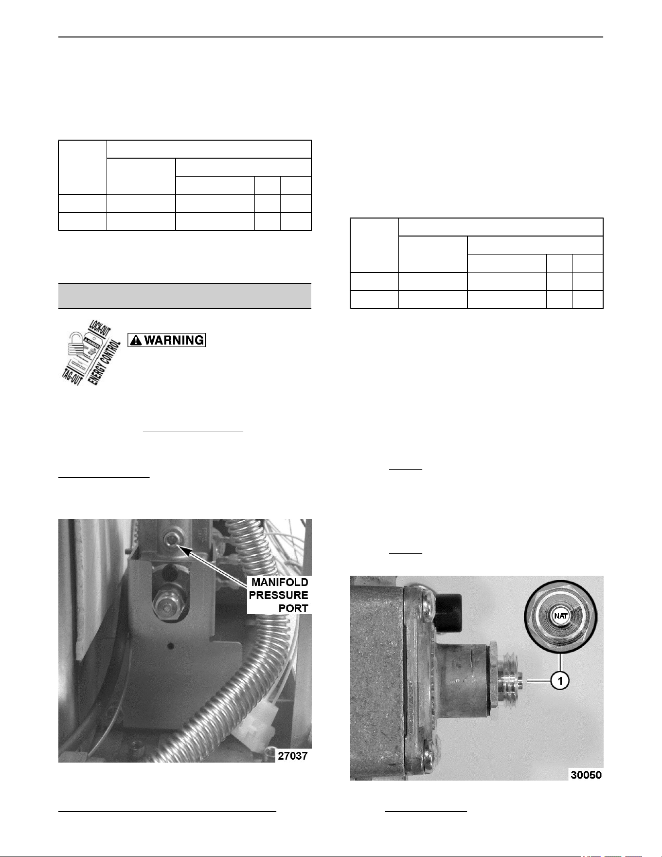
3.
Remove the plug from the manifold pressure
port.
Fig. 68
4. Install
hose barb adapter and attach manometer
tube.
5. Turn gas supply to the oven back on.
6. Plug the unit in and turn the power switch ON.
7. Set the temperature control to its highest setting
and allow burner to ignite.
NOTE: The burner must be lit during test.
NOTE: Accurate gas pressure readings can only be
made with the gas on and the burner lit.
GAS
TYPE
PRESSURE READING (IN W.C.)
MANIFOLD
LINE
RECOMMEND MIN MAX
Natural 5.0 8.0 6 14
Propane 10 11.0 11 14
NOTE: If the incoming line pressure to the valve is
less than the minimum stated, then the manifold
pressure will not be maintained.
NOTE: If gas valve cap is removed, or reversed for
gas type, ensure sealing washer is installed between
the gas valve and cap.
NATURAL GAS
•
If the incoming pressure to the valve is between
6” WC and 14” for Natural gas and the manifold
pressure is not maintaining 5” WC, and the cap
(1,
Fig. 69) is correctly positioned, replace the
valve.
PROPANE
•
If the incoming pressure to the valve is between
11” WC and 14” for Propane gas and the manifold
pressure is not maintaining 10” WC, and the cap
(1,
Fig. 70) is correctly positioned, replace the
valve.
Fig. 69
VC4G & VC6G SERIES FULL SIZE CONVECTION OVENS - SERVICE PROCEDURES AND ADJUSTMENTS
Page 31 of 86 F24682 Rev. J (0825)
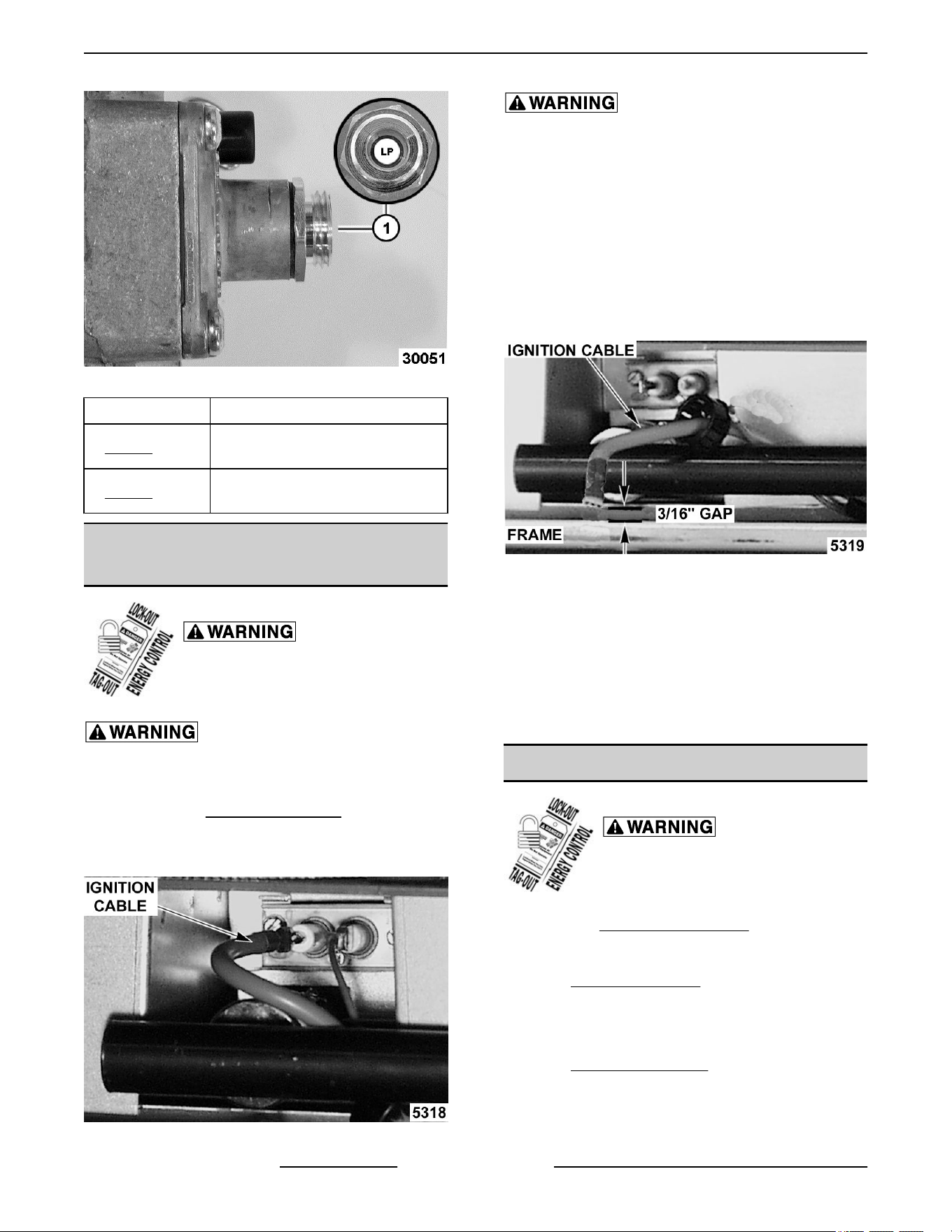
Fig. 70
ITEM DESCRIPTION
1, Fig. 69
Cap position for natural gas
(stamped NAT).
1, Fig. 70
Cap position for propane gas
(stamped LP).
VERIFICATION OF SPARK AT
IGNITOR
Disconnect the electrical power to
the machine and follow lockout /
tagout procedures.
SHUT OFF THE GAS BEFORE SERVICING THE
UNIT.
1. Remove the Bottom Front Cover.
2. Disconnect the high voltage "ignition cable" from
the spark ignitor.
Fig. 71
DO NOT HOLD THE WIRE WITH YOUR HANDS
FOR
THIS TEST. THE MANUAL GAS VALVE MUST
BE CLOSED.
3. Clamp the ignition cable in a manner that will
position the end of the cable 3/16" from the oven
frame (bare metal surface).
NOTE: It is critical that the cable be held 3/16" away
from the surface of the oven frame or sparking may
not occur even though the sparking circuit is
functioning properly.
Fig. 72
4. Plug the oven in and set the temperature control
to the maximum setting.
5. Turn the power switch ON.
6. Sparking should occur after a 4 second delay, for
a duration of 7 seconds then repeat twice after a
15 second purge time. Arching from the ignition
cable to the oven frame should be observed.
DOOR SWITCH ADJUSTMENT
Disconnect the electrical power to
the machine and follow lockout /
tagout procedures.
1. Remove TOP FRONT COVER
2. Door operation:
A. Independent doors - The switch actuator
should be operated by the switch lever when
the right door is between 1" and 1 ½ " from
being closed.
B. Simultaneous doors - The switch actuator
should be operated by the switch lever when
the right door is ½ " from being closed.
VC4G & VC6G SERIES FULL SIZE CONVECTION OVENS - SERVICE PROCEDURES AND ADJUSTMENTS
F24682 Rev. J (0825) Page 32 of 86
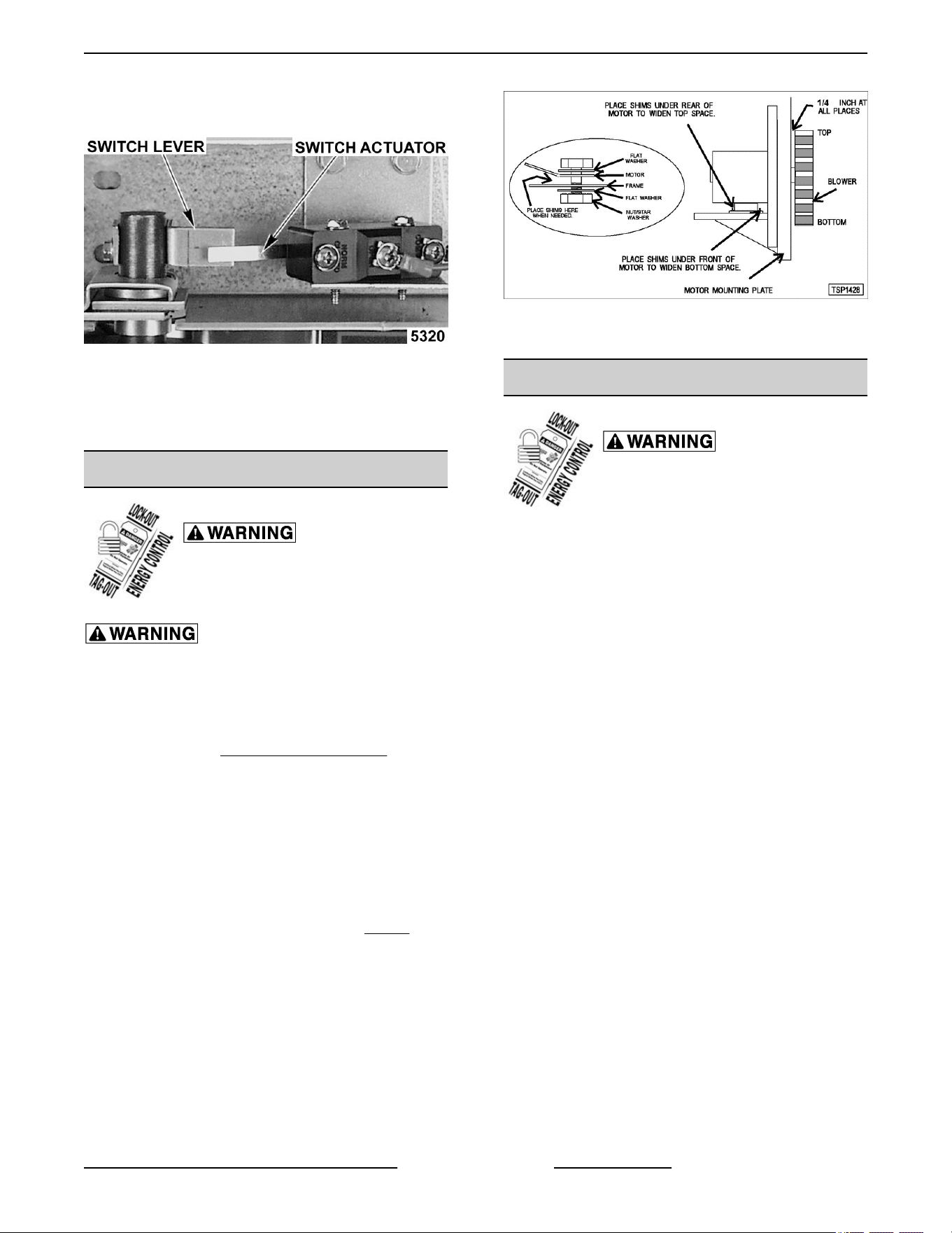
3. If adjustment is necessary, bend the switch
actuator to obtain the proper setting.
Fig. 73
4. Install the top front cover.
5. Apply power to the oven and check for proper
operation.
BLOWER ADJUSTMENT
Disconnect the electrical power to
the machine and follow lockout /
tagout procedures.
SHUT OFF THE GAS BEFORE SERVICING THE
UNIT.
1. Remove the blower motor and mounting
assembly by following steps 1 through 8 as
outlined under BLOWER AND MOTOR.
2. Loosen the motor mounting bolts.
3. Adjust the motor position until the blower is
parallel to and 1/4 inch away from the motor
mounting plate. Check for squareness of the
blower to the motor mounting plate at the top,
bottom, left and right of the blower.
A. If the blower is square then tighten motor
mounting bolts and proceed to Step 4.
B. If the blower is not square continue
adjusting until proper spacing is achieved
then tighten motor mounting bolts.
NOTE: If necessary, place shims between motor and
frame.
Fig. 74
4. Reverse the procedure to install.
DOOR ADJUSTMENT
Disconnect the electrical power to
the machine and follow lockout /
tagout procedures.
1. Check the doors to make sure they have a .125
(1/8") gap between them and that the vertical
edge of the door is parallel to the vertical door
seal. If the doors are not positioned in this
manner, adjust the doors as described.
VC4G & VC6G SERIES FULL SIZE CONVECTION OVENS - SERVICE PROCEDURES AND ADJUSTMENTS
Page 33 of 86 F24682 Rev. J (0825)
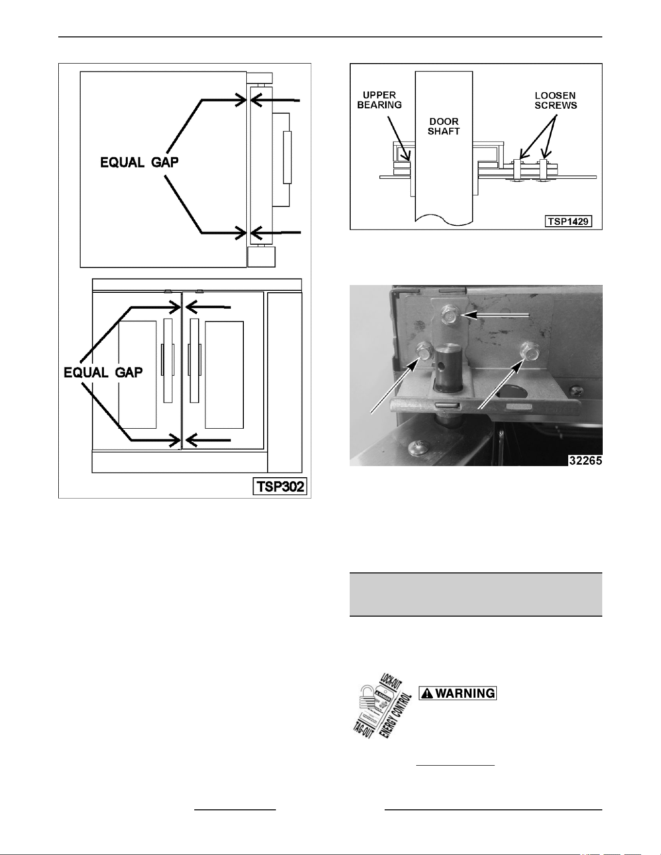
Fig. 75
2. Remove the .
3. Loosen the screws/bolts that secure the upper
door brackets just enough to allow door
movement.
Figure Shown below (Left Side) is ending at
Serial Number 481907145.
Fig. 76
Figure shown below (Left Side) is starting at
Serial Number 481907146.
Fig. 77
4. Move
the door until proper alignment is achieved
then tighten the screws/bolts on the upper door
bearing hardware.
5. Repeat and on the opposite door, if necessary.
6. Install
DOOR STRIKE ADJUSTMENT
(INDEPENDENT DOORS)
NOTE: For units with serial number starting with 48
made
after 8/12/07 and serial number starting with 54
made after 8/26/07.
Disconnect the electrical power to
the machine and follow lockout /
tagout procedures.
1.
Remove
Top Front Cover.
2. Open
the doors and inspect door strike for proper
shape.
VC4G & VC6G SERIES FULL SIZE CONVECTION OVENS - SERVICE PROCEDURES AND ADJUSTMENTS
F24682 Rev. J (0825) Page 34 of 86
A. Replace if bent. Do not bend strike plate.
B.
If adjustment is necessary, loosen
fasteners, close doors and insure contact
between door inner surface and upper
horizontal seal. Slide door strike plate until
contact with roller latch is made. Tighten
strike plate fasteners.
Fig. 78
3.
Open and close the doors several times while
observing the roller latch and strike plate
operation.
A. Replace roller latch if malfunctioning as
outlined under
ROLLER LATCH
ASSEMBLY (INDEPENDENT DOORS)
and adjust as outlined in this procedure.
4.
Each oven door should open with a force of 8 to
25 pounds when pulled at the handle. The
adjustments must allow the doors to remain
closed during normal operation and allow
opening without exertion by the user.
DOOR CATCH BALL ADJUSTMENT
(INDEPENDENT DOORS)
NOTE: For units with serial number starting with 48
made before 8/13/07 and serial number starting with
54 made before 8/27/07.
Disconnect the electrical power to
the machine and follow lockout /
tagout procedures.
1.
Remove
Top Front Cover.
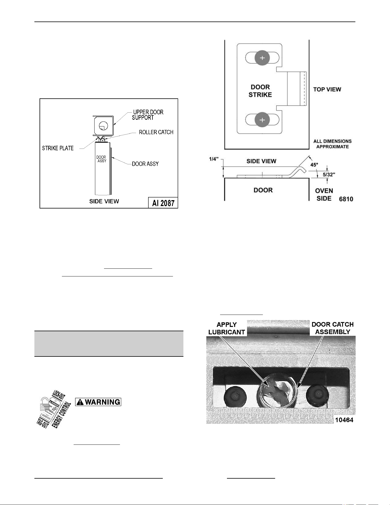
2. Open
the doors and inspect door strike for proper
shape.
Fig. 79
A. Replace
if bent and adjust as outlined in this
procedure.
3. Open and close the doors several times while
observing the catch ball operation.
A. Replace if malfunctioning and adjust as
outlined in this procedure.
NOTE: Shims may be required under the door strike,
before the proper door tension adjustment can be set.
4. Apply lubricant at the top of the door catch
assembly to lubricate the internal spring. See
LUBRICATION.
Fig. 80
5.
Close the doors and check them for proper
alignment.
VC4G & VC6G SERIES FULL SIZE CONVECTION OVENS - SERVICE PROCEDURES AND ADJUSTMENTS
Page 35 of 86 F24682 Rev. J (0825)
A. Doors
should be centered and parallel at the
top and bottom in the oven cavity opening
as outlined under
DOOR ADJUSTMENT.
6. Open
right side door and view the left side catch
ball and door strike position. Ensure catch ball is
resting upon the angular surface of door strike.
Repeat on opposite door.
NOTE: If catch ball is striking the flat surface on door
strike, shims will be required under the door catch
assembly.
NOTE: The catch ball should make contact near the
center of door strike.
A. If adjustment is necessary, loosen mounting
screws then slide door strike from front to
back until roller ball rests upon the angular
surface of the door strike. Tighten screws
and check operation.
B. If proper adjustment cannot be achieved,
add shims beneath the door strike. Repeat
step 6.
NOTE: DO NOT BEND THE DOOR STRIKE.
7. Each oven door should open with a force of 8 to
25 pounds when pulled at the handle. The
adjustment must allow the doors to remain
closed during normal operation and allow
opening without exertion by the user.
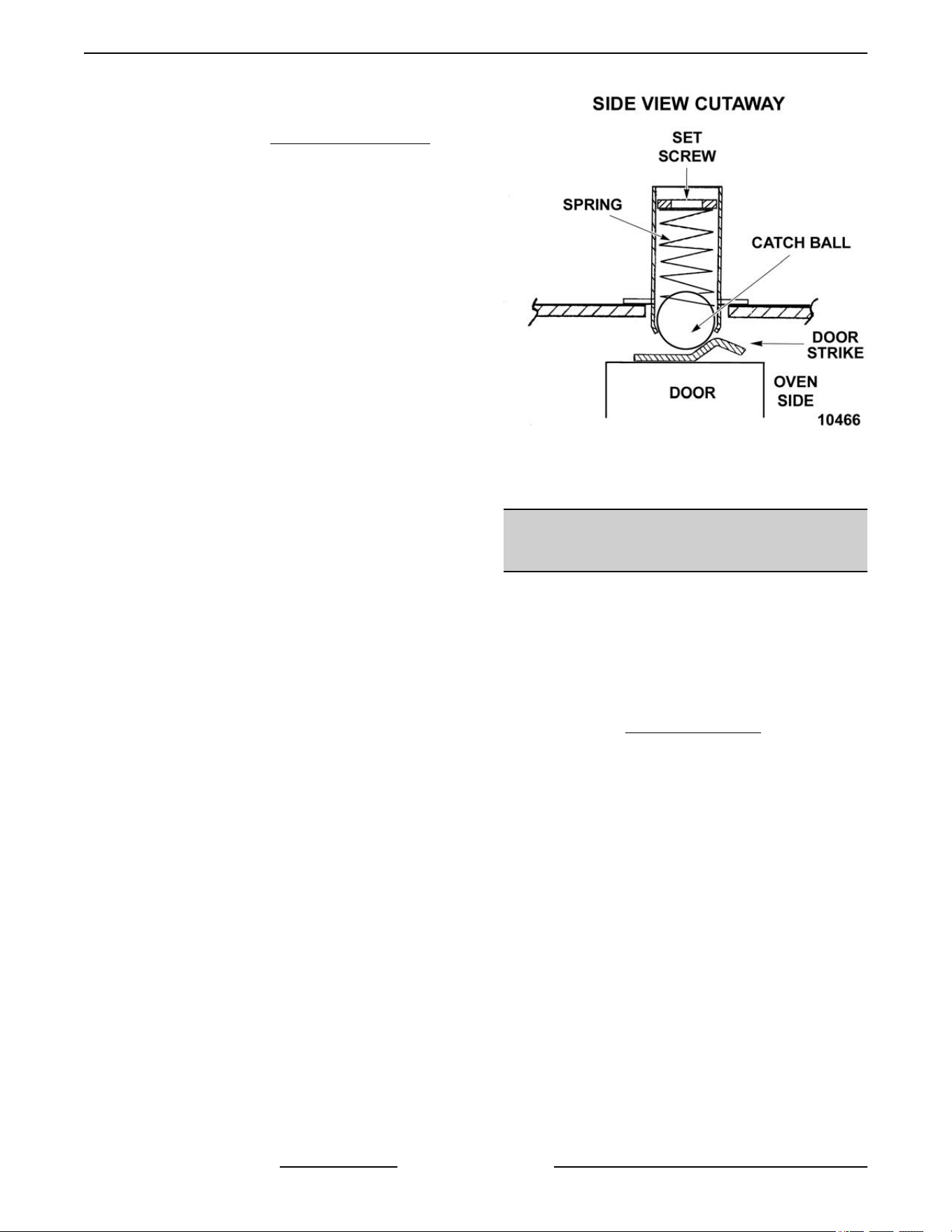
NOTE: The amount of tension on catch ball
determines the opening force of door.
A. Adjust catch ball tension as follows:
1) Turn set screw inside the catch
assembly housing clockwise to
increase tension on catch ball and
counterclockwise to decrease tension
on catch ball.
Fig. 81
2)
Continue adjustment until proper door
operation is achieved.
DOOR CHAIN ADJUSTMENT
(SIMULTANEOUS DOORS)
Introduction
When
the oven doors are in proper adjustment, as the
doors come together, the right door will lead the left
door in closing by about 1/4 inch. The doors will feel
like they are self closing the last ½ inch of travel.
Procedure
1. Remove the
Bottom Front Cover .
2.
Close doors and check door chain for factory
setting.
A. Turnbuckles should be 5 to 5 ½ inches
apart.
B. Short eye bolt should be connected to the
end of the chain that goes to the front of the
sprocket.
C. 2 links of the chain should not be engaged
at the rear of the sprocket.
D. Chain must be tight enough that the doors
move simultaneously when opened or
closed.
E. When the doors are opened, the
turnbuckles will move away from each other.
F. The stop cable must be positioned where it
moves freely and does not get pinched.
3. Position door chain assembly to factory setting if
the conditions in step 2 are not met.
VC4G & VC6G SERIES FULL SIZE CONVECTION OVENS - SERVICE PROCEDURES AND ADJUSTMENTS
F24682 Rev. J (0825) Page 36 of 86
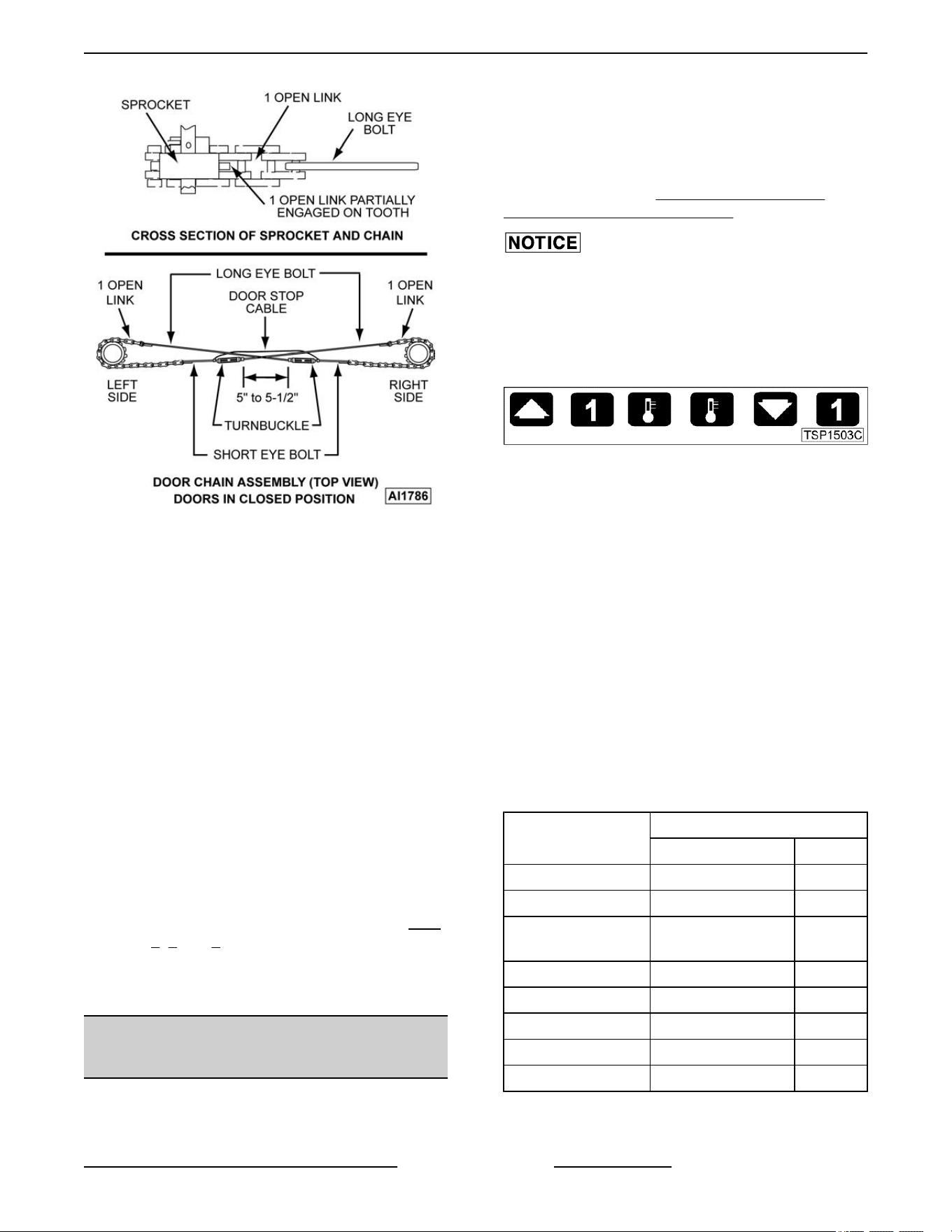
Fig. 82
4. If
right door does not lead the left door in closing:
A. Loosen locknuts on both turnbuckles.
B. Loosen left turnbuckle.
C. Tighten right turnbuckle.
D. Tighten locknuts on both turnbuckles.
5. If the right door leads the left door by more than
3/8 inch:
A. Loosen locknuts on both turnbuckles.
B. Loosen right turnbuckle.
C. Tighten left turnbuckle.
D. Tighten locknuts on both turnbuckles.
6. Check door for proper operation.
NOTE: The locknuts must be tight during testing or
the adjustment will not hold.
A. If doors do not close properly, repeat
Step
4, 5 and 6.
B. If
doors operate properly, continue to step 7.
7. Install the lower front cover.
COMPUTER CONTROL (VC4GC/
VC6GC)
Operation
Refer
to the Instructions Manual for specific operating
instructions.
Setup Mode
NOTE: Use
the setup mode to verify that the control
is configured to the factory settings which result in the
proper operation of the oven. If the CAL1 parameter
is other than zero, determine if it is still needed before
resetting to zero. See
COMPUTER CONTROL
CALIBRATION (VC4GC/VC6GC).
Changing the C_F, InP1, rL1 & rH1 parameters will
default all menus.
1. Use
this key sequence to access the setup mode.
Up arrow; Rack 1; Temperature; Temperature;
Down arrow; Rack 1
Fig. 83
2. Once in the setup mode the display will alternate
between the parameter and programmed data.
• To change data to the factory setting, use
the arrow keys.
• To select the next parameter, press the
Rack 1 key.
• After the last Parameter and Data is viewed,
press the Rack 1 key a final time to exit the
setup mode and return to operations mode.
The current set point temperature will be
displayed.
• After 1 minute of no key activations, the
control will return to operation mode.
3. Listed are the parameters and data you should
find.
MENU
ALTERNATING ON DISPLAY
PARAMETER DATA
Celsius_Fahrenheit C_F F
Guard Band gb 4000
Temperature
Compensation
tcnP OFF
Input Type 1 InP1 J
Range Low 1 rL1 75
Range High 1 rH1 500
Hysteresis HYS1 3
Calibration Offset CAL1 0
VC4G & VC6G SERIES FULL SIZE CONVECTION OVENS - SERVICE PROCEDURES AND ADJUSTMENTS
Page 37 of 86 F24682 Rev. J (0825)
MENU
ALTERNATING ON DISPLAY
PARAMETER DATA
Exit Setup Mode
and return to
Operation Mode.
set point temperature is
displayed or if call for heat,
dashes (----) displayed.
Probe Test
1.
Set the control to 350°F.
2. Access the back of the control panel to
disconnect the probe lead wires.
3. Install a jumper wire across the probe terminals.
This will simulate room temperature.
A. If the heat light comes on and the actual
temperature is room temperature, replace
the probe.
B. If the heat light does not come on or the
actual temperature is not room temperature,
replace the control.
Solid State Relay Test
1. Remove the
Right Side Panel.
2.
Set the temperature to 350°F or high enough to
keep the heat ON for several minutes.
3. Check for +5 VDC on input side of SSR
(terminals 3 & 4).
A. If +5 VDC is present, continue to step 4.
B. If no voltage is present, computer control is
not functioning properly.
4. Check for 120 VAC at load side of SSR (terminals
1 & 2).
A. If no voltage is present, solid state relay is
not functioning properly.
1) Replace the SSR and check for proper
operation.
B. If 120 VAC is present, component is
functioning properly.
5. Re-assemble oven and check for proper
operation.
COMPUTER CONTROL
CALIBRATION FOR WATLOW
CONTROLLER (VC4GC/VC6GC)
1. Place a thermocouple in the geometric center of
the oven cavity.
2.
Press the set key then temperature key to enter
the temperature set mode.
A. The display will alternate between the term
"StPt" (set point) and the current oven
temperature setting.
B.
Press the up or down arrow keys to make
the proper selection.
C. Press the set key again to save the change
and exit the temperature set mode.
3. Allow the oven temperature to stabilize (normally
3 cycles).
4. Set the ON-OFF-COOL DOWN switch to ON.
A. If the set point temperature is 350°F,
proceed to step 4.
B. If the set point temperature is other than
350°F, proceed to step 3 to change the
temperature.
5. Compare the controls set point temperature to
the thermocouple meter reading when the heat
light goes out.
A. A temperature variance more than 5°F
indicates an adjustment is needed.
1) To make the adjustment, proceed to
step 6.
2) If temperature variance is less than
5°F, computer control is functioning
properly.
6. Enter the .
A. Advance through the menu until CAL1
(Calibration Offset) appears.
1) If the thermocouple reading is higher
than set point temperature, press the
down arrow key and enter a negative
offset value that is equal to the number
of degrees above the 5°F tolerance.
2) If the thermocouple reading is lower
than set point temperature, press the
up arrow key and enter a positive offset
value that is equal to the number of
degrees below the 5°F tolerance.
3) Exit the setup mode.
7. Allow the oven to cycle at least two times
between adjustments.
A. If the temperature variance still differs
more than 5°F from the set point, verify the
correct calibration offset value was entered
and retained.
1) Adjust the calibration offset value as
outlined in step 6, until the cycling
temperature is within tolerance.
VC4G & VC6G SERIES FULL SIZE CONVECTION OVENS - SERVICE PROCEDURES AND ADJUSTMENTS
F24682 Rev. J (0825) Page 38 of 86

B. If
the above adjustment cannot be obtained,
replace the computer control and check for
proper operation.
FLAME SENSE CURRENT TEST
VC4G & VC6G SERIES FULL SIZE CONVECTION OVENS - SERVICE PROCEDURES AND ADJUSTMENTS
Page 39 of 86 F24682 Rev. J (0825)
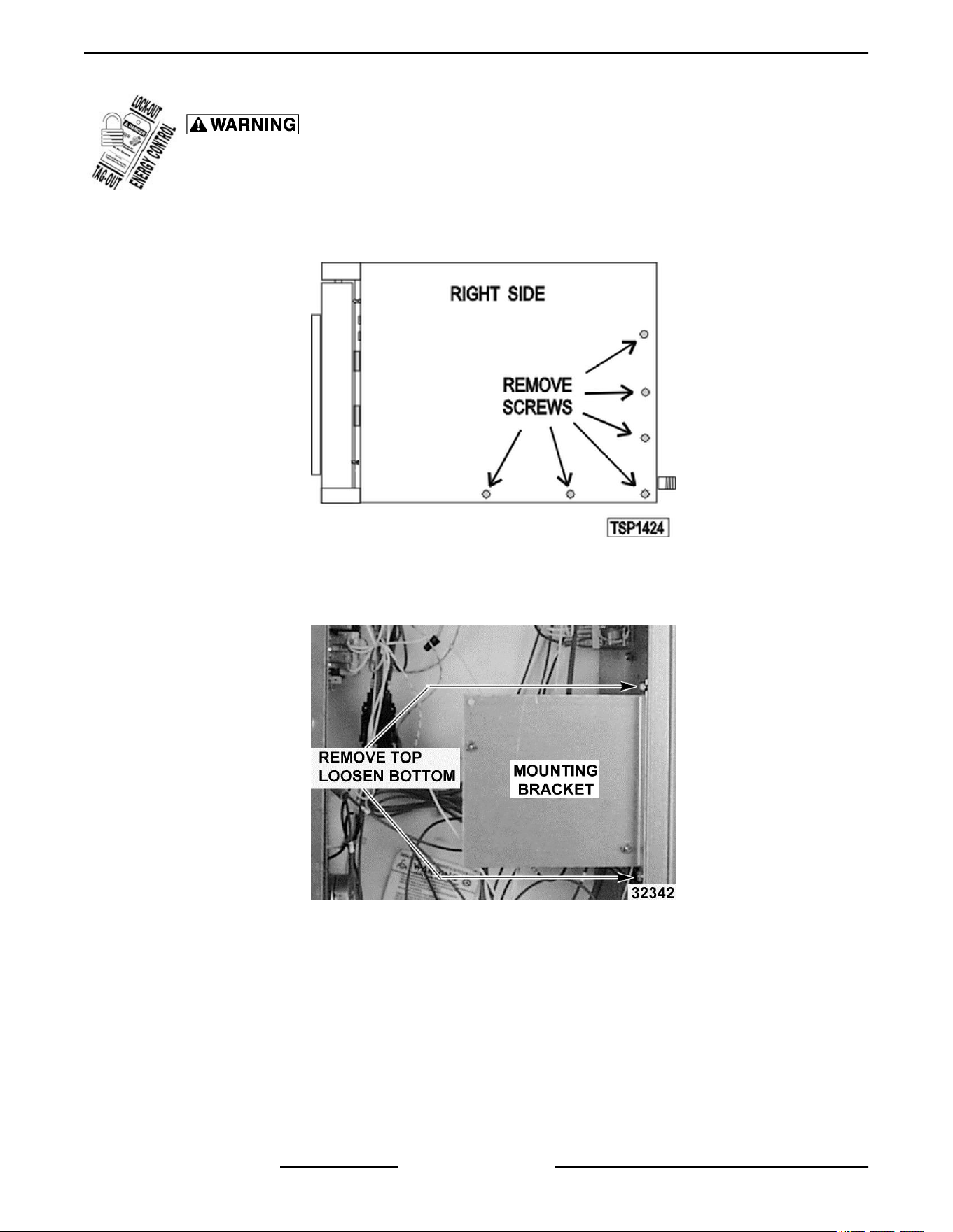
Disconnect the electrical power to the machine and follow lockout / tagout procedures.
1.
Remove screws securing right side of the top front cover, bottom front cover and control panel.
2. Remove right side panel mounting screws.
Fig. 84
3.
Pull right side panel out from the bottom then down to remove.
4. Remove top screw and loosen bottom screw securing the ignition control module mounting bracket.
Fig. 85
5.
Position bracket horizontally by pulling forward 90 degrees, with ignition module facing up for accessibility.
6. Re-apply power to unit.
7. Set VOM meter to read Micro Amps.
8. Place red (Positive) lead on FC+ and black (Negative) lead on FC- terminals on ignition module to test.
VC4G & VC6G SERIES FULL SIZE CONVECTION OVENS - SERVICE PROCEDURES AND ADJUSTMENTS
F24682 Rev. J (0825) Page 40 of 86
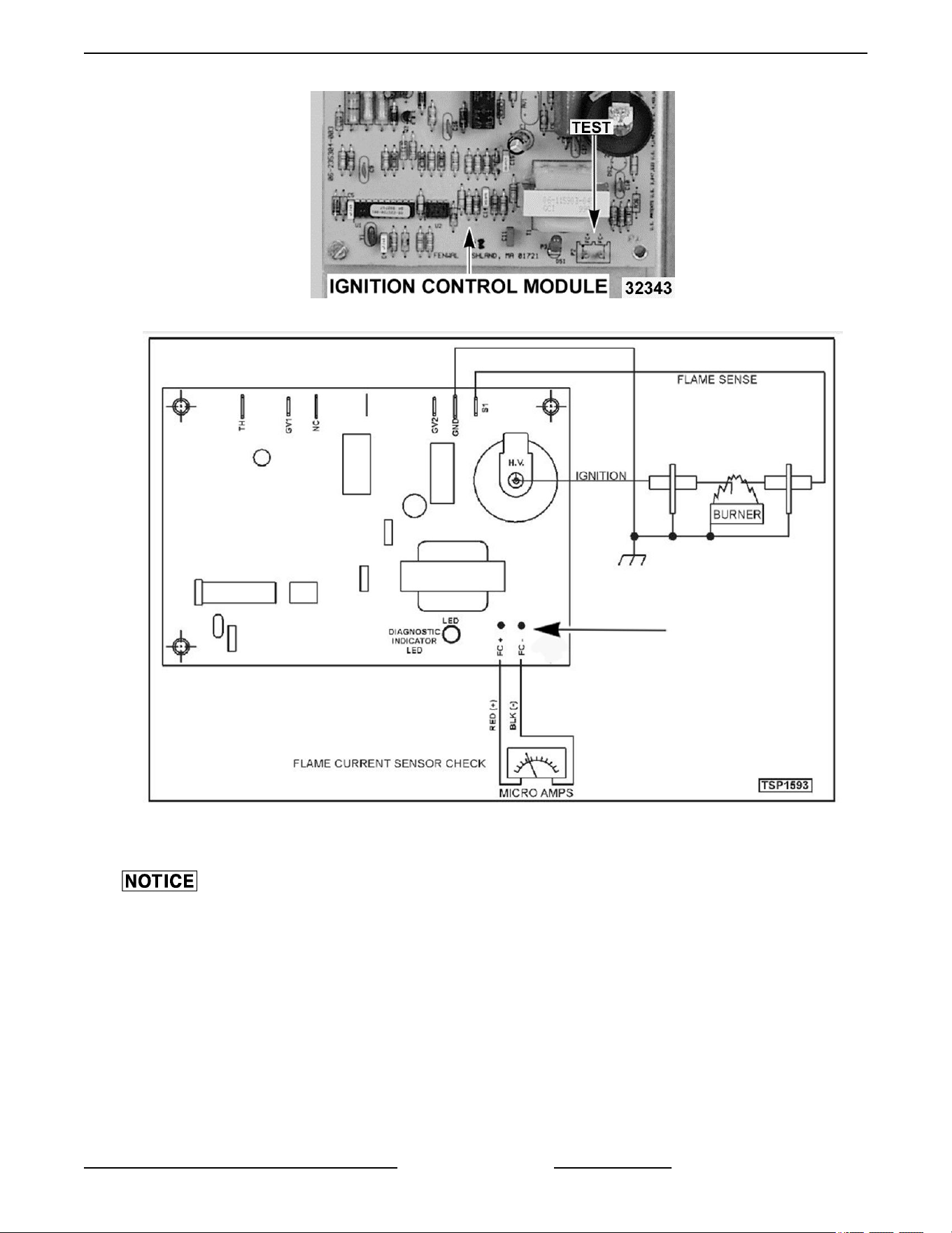
Fig. 86
Fig. 87
9.
Set the oven to call for heat and measure the Micro Amps reading.
Micro Amp reading from the flame sensor should measure a minimum of 0.7 Micro Amps to maintain burner
ignition.
• If
Micro amp reading is correct and the burner lights but does not maintain flame, replace ignition module.
• If Micro Amp reading is NOT correct, check wiring from flame sensor/igniter to the ignition module. If wiring
is OK, adjust, clean or replace flame sensor/igniter.
10. Install ignition control module mounting bracket and right panel.
11. Verify operation.
VC4G & VC6G SERIES FULL SIZE CONVECTION OVENS - SERVICE PROCEDURES AND ADJUSTMENTS
Page 41 of 86 F24682 Rev. J (0825)
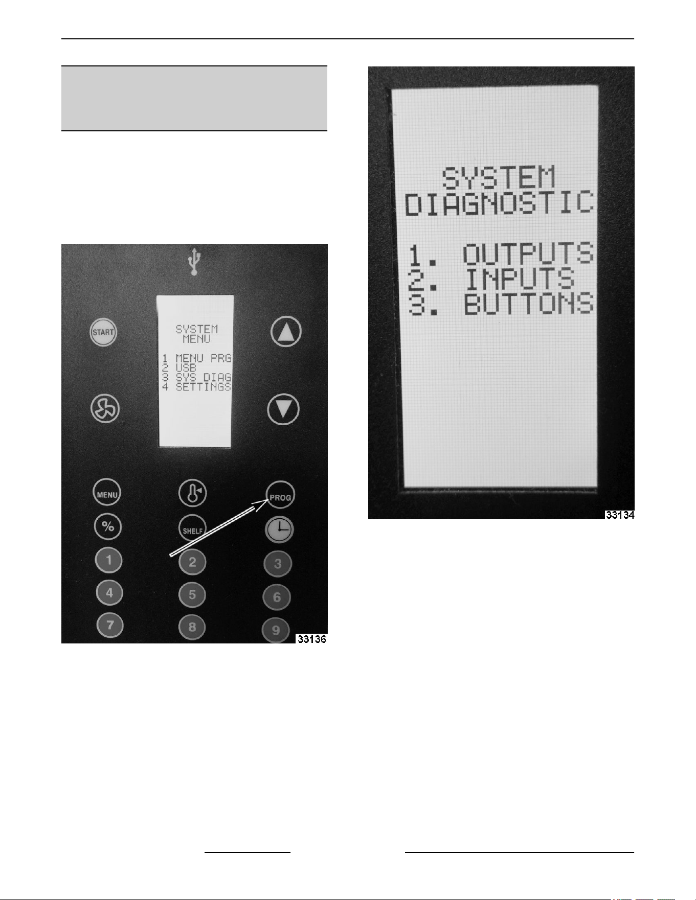
SERVICE PROGRAMMING AND
TESTING FOR 3700 COMPUTER
CONTROL
NOTE: Press X to go back to previous screen. User
interface system menu program instructions for
MENU PRG and USB are located in COMPUTER
CONTROLS GUIDE.
SYSTEM DIAGNOSTIC
1.
Press Program.
Fig. 88
2. Press number 3 for SYS DIAG.
• System Diagnostic menu will appear.
Fig. 89
• 1. OUTPUTS
VC4G & VC6G SERIES FULL SIZE CONVECTION OVENS - SERVICE PROCEDURES AND ADJUSTMENTS
F24682 Rev. J (0825) Page 42 of 86
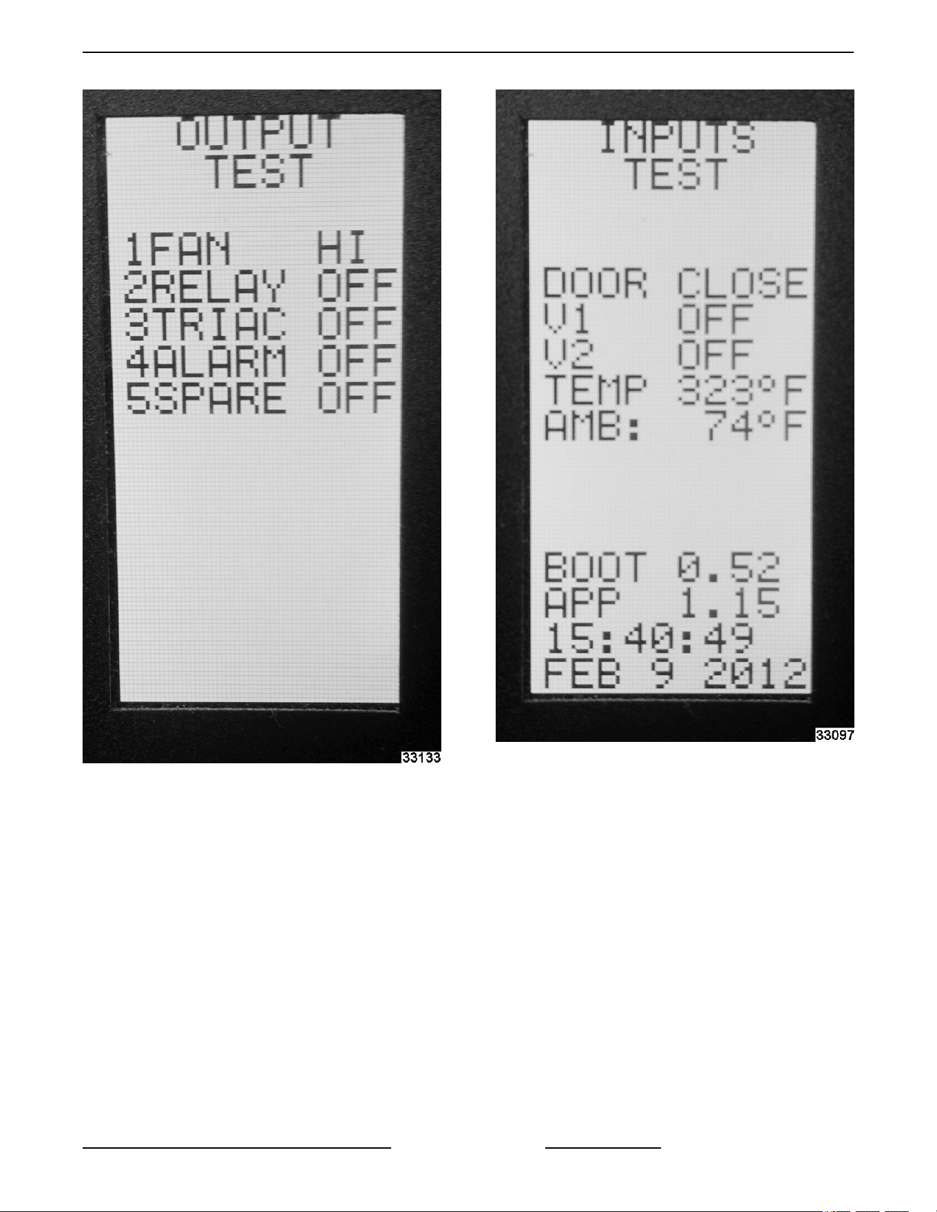
Fig. 90
• Press corresponding number for
testing function selection.
Example: Press 1 to test Fan
function.
• 2. INPUTS
Fig. 91
• Check status of a function.
Example: Door is open or close.
• 3. BUTTONS
VC4G & VC6G SERIES FULL SIZE CONVECTION OVENS - SERVICE PROCEDURES AND ADJUSTMENTS
Page 43 of 86 F24682 Rev. J (0825)
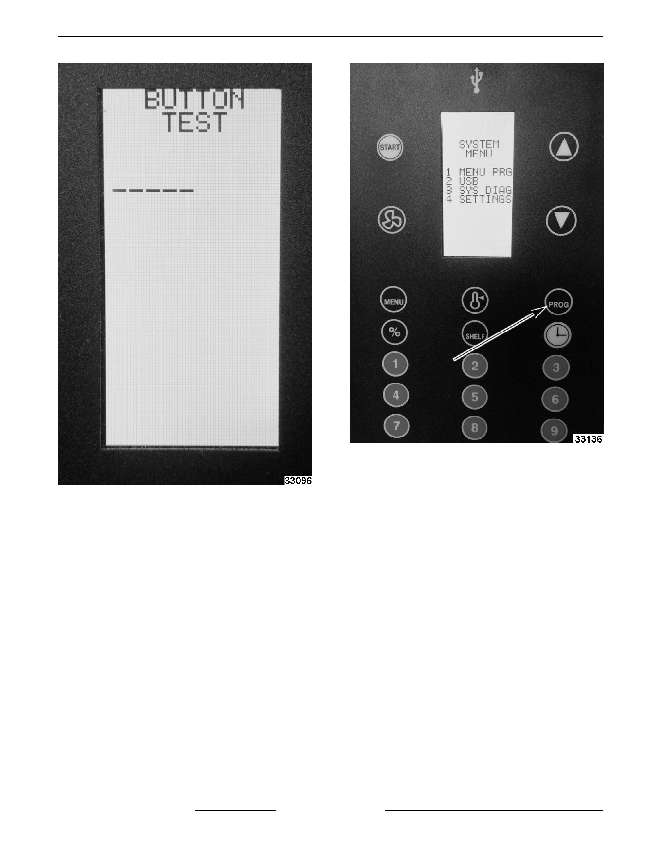
Fig. 92
• Button test verifies each button is
programed and working.
Example: Push a button on the
keypad to verify it is connected
and working. Each buttons
function shows on display.
SYSTEM SETTINGS
1. Press Program.
Fig. 93
2. Press 4 for SETTINGS.
• System Settings menu will appear.
VC4G & VC6G SERIES FULL SIZE CONVECTION OVENS - SERVICE PROCEDURES AND ADJUSTMENTS
F24682 Rev. J (0825) Page 44 of 86
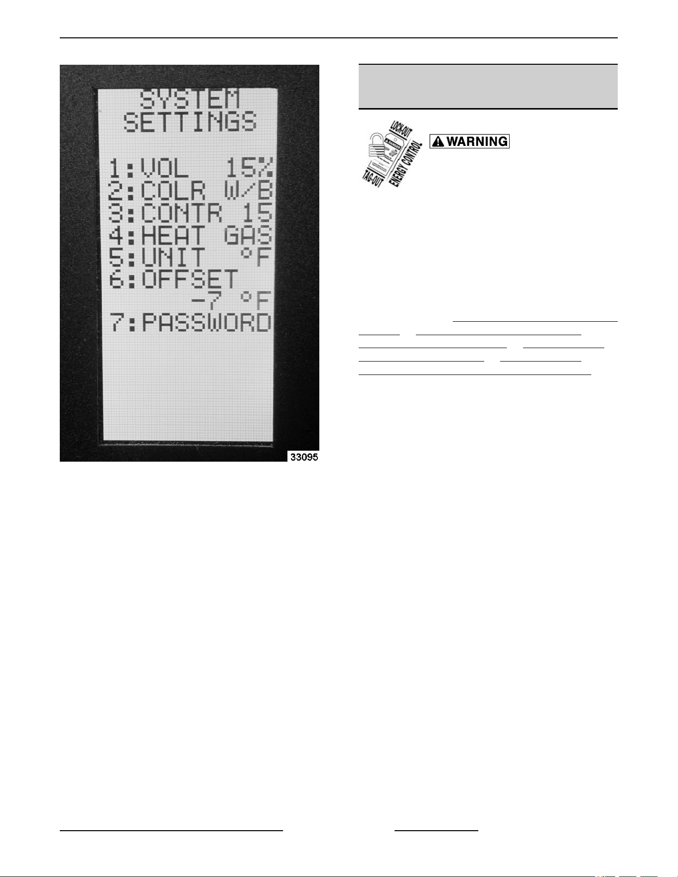
Fig. 94
• Press corresponding number to change
settings. Example: Press 4 to change HEAT
to Electric.
SETTING TEMPERATURE OFFSET
• Check center of oven temperature with
temperature tester.
• Press number 6.
• Use arrow keys to offset DISPLAY
temperature setting to match center of
oven temperature.
CONVECTION MOTOR
CENTRIFUGAL SWITCH (TEST)
Certain procedures in this section
require electrical test or
measurements while power is
applied to the machine. Exercise
extreme caution at all times and
follow Arc Flash procedures. If test
points are not easily accessible,
disconnect power and follow
Lockout/Tagout procedures, attach
test equipment and
reapply power to
test.
NOTE: Reference
VC4GS, VC6GS Mechanical (KX)
Controls or VC4GS, VC6GS Mechanical (KX)
Controls, Roast & Hold Option or VC4GS, VC6GS
Mechanical (KX) Controls or VC4GS, VC6GS
Mechanical (KX) Controls, Roast & Hold Option.
1. Verify heat & power light are lit.
2. Verify motor is running.
3. Verify 120V is being sent to centrifugal switch.
4. Verify 120V is being sent to heat relay coil.
5. If 120V not present at heat relay coil, replace
BLOWER AND MOTOR.
VC4G & VC6G SERIES FULL SIZE CONVECTION OVENS - SERVICE PROCEDURES AND ADJUSTMENTS
Page 45 of 86 F24682 Rev. J (0825)
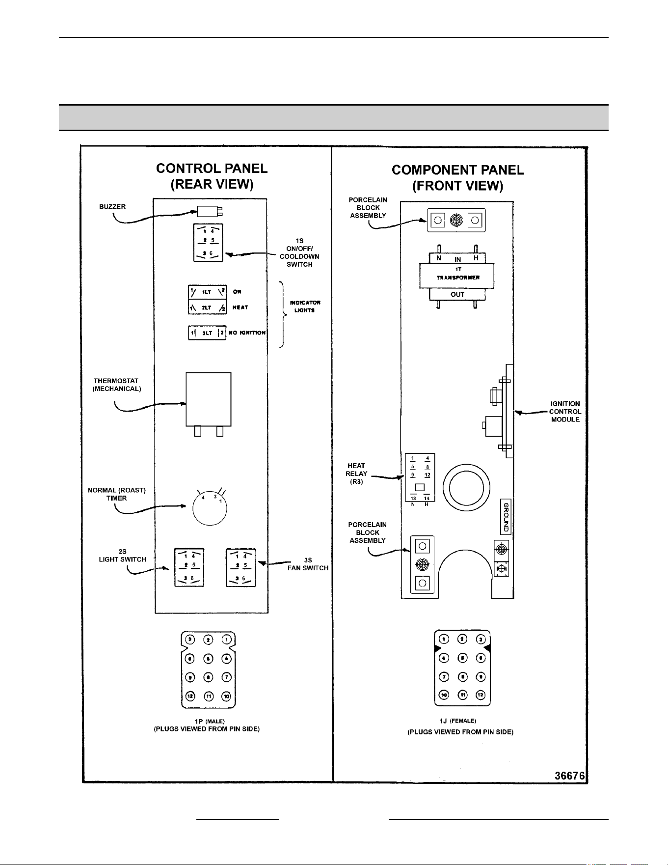
ELECTRICAL OPERATION
COMPONENT LAYOUT AND FUNCTION
Fig. 95
VC4G & VC6G SERIES FULL SIZE CONVECTION OVENS - ELECTRICAL OPERATION
F24682 Rev. J (0825) Page 46 of 86

Power Switch (S1) .... Determines the mode of operation; ON, OFF, or COOL DOWN.
Oven Light Switch
(S2) ...................
Controls the oven cavity lights.
Fan Speed Switch Hi/
Low (S3) ..............
Controls blower motor speed between Hi and Low settings.
Function Switch
(S3) ...................
Selects
the cooking mode of the oven between Normal ROAST or ROAST & HOLD and
is used in conjunction with the ROAST & HOLD timer during ROAST & HOLD cooking.
The selected mode also determines the fixed blower speed of Hi for Normal ROAST and
Low for ROAST & HOLD. In ROAST & HOLD mode only, energizes the hold relay (R2).
Available on models with ROAST & HOLD option only. On Standard models (S3)
becomes the Function Switch.
Buzzer ................ Signals the end of a Normal ROAST cycle (normal cooking) when time expires on the
Normal ROAST timer.
Door Switch .......... Allows the oven to operate when the doors are closed but stops the oven from operating
when the doors are opened.
Blower Motor ......... Operates the oven cavity blower (convection fan). Also, an internal centrifugal switch on
the motor is utilized to allow the connection of power to the heat relay (R3) when the
motor is at operating speed.
Motor Speed Relay
(R1) ...................
Supplies power to the blower motor through (R1) relay contacts. Available on models
with Cook & Hold option only.
Hold Relay (R2) ....... Hold relay (R2) supplies power to the Hold thermostat for maintaining the fixed hold
temperature in the oven cavity, after the ROAST & HOLD time expires.
Solid State
Temperature
Control ...............
Monitors temperature sensor and regulates the oven cavity temperature by controlling
the heat relay (R3) through the blower motor centrifugal switch contacts.
High Limit
Thermostat ...........
Protects the oven from temperatures above 550°F by removing power from the 1st valve
(safety) on the dual solenoid gas valve which stops the flow of gas to the burner. Auto
resets at 500°F.
SSR1 & SSR2 ......... When SSR1 is energized by computer control, connects power to blower motor for Hi fan
speed operation in normal ROAST mode. In ROAST & HOLD Mode only, SSR1 is de-
energized and SSR2 is energized by computer control and connects power to blower
motor for Low fan speed operation.
Ignition Control
Module ...............
Controls the gas ignition cycle - Energizes the 2nd valve (main) on the dual solenoid gas
valve, generates spark for burner ignition, monitors the presence of a flame and controls
the No Ignition light. The ignition times are: 4 second self diagnostic test (initial power
ON); 7 second ignition trial; 3 ignition trials with a 15 second purge between each trial.
Igniter/Flame
Sense .................
Ignites the gas and senses the presence of a flame. The flame presence generates a
micro-amp "flame sense" current that is monitored by the ignition control module. A flame
sense current of 0.7 micro amp (minimum) is required to maintain burner ignition.
Power On Light ....... Lit whenever the power switch (S1) is turned to ON or Cool Down mode.
Heat Light ............ Lit whenever temperature control is calling for heat.
No Ignition Light ...... Lit when power is turned ON, during ignition trial & gas purge time and when no flame is
detected by flame sensor. If the oven fails to ignite after 3 attempts, it will remain lit until
power is reset.
Temperature Probe ... Senses the oven temperature for the solid state temperature control or the computer
control. Converts the temperature into a resistance valve which is monitored by the
temperature control board. The probe is an RED (Resistance Temperature Detector) of
the Thermistor type. As temperature increases, the resistance valve decreases.
VC4G & VC6G SERIES FULL SIZE CONVECTION OVENS - ELECTRICAL OPERATION
Page 47 of 86 F24682 Rev. J (0825)
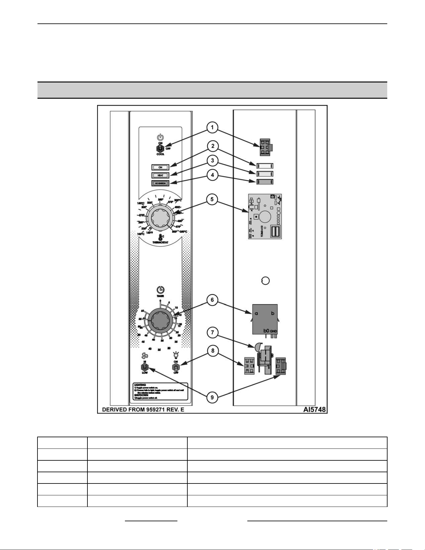
Gas Valve (Dual
Solenoid) .............
Allows
gas flow to the burner when the 1st valve (safety) and 2nd valve (main) solenoid
coils are both energized.
Cooling Fan .......... Circulates cooler air from rear of oven forward to cool components in the control area.
COMPONENT LAYOUT AND FUNCTION - STARTING SN 482080151
Fig. 96
Item Name / Electrical Callout Function
1 Power Toggle Switch (S1) Determines the mode of operation: ON, OFF, or COOL DOWN.
2 Indicator "ON" Light Indicates when oven is powered on.
3 Indicator "HEAT" Light Indicates when oven is heating.
4 Indicator "NO IGNITION" Light Indicates no flame detected by flame sensor.
5 Temperature Control Analog temperature controller.
VC4G & VC6G SERIES FULL SIZE CONVECTION OVENS - ELECTRICAL OPERATION
F24682 Rev. J (0825) Page 48 of 86
Item Name / Electrical Callout Function
6 Timer Allows user to set cooking timer.
7 Alarm / Buzzer Signals the end of a cook cycle when cooking time ends.
8 Oven Light Switch (S2) Controls the oven cavity lights.
9 Fan Speed Switch (S3) Controls blower motor speed between High and Low settings.
VC4G & VC6G SERIES FULL SIZE CONVECTION OVENS - ELECTRICAL OPERATION
Page 49 of 86 F24682 Rev. J (0825)
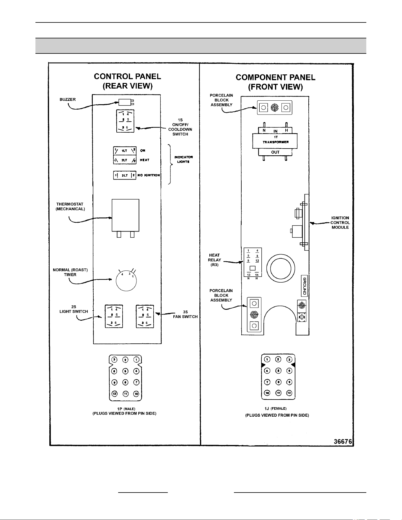
COMPONENT LOCATION
Fig. 97
VC4G & VC6G SERIES FULL SIZE CONVECTION OVENS - ELECTRICAL OPERATION
F24682 Rev. J (0825) Page 50 of 86

SEQUENCE OF OPERATION
WKGD With Roast & Hold Option (Solid State
Temperature Control)
Normal Roast Cycle
1.
Conditions.
A. Oven connected to correct voltage.
1) L1 (HOT) to power switch (S1).
2) L2 (NEUTRAL or SECOND LINE) to
one side of the following components:
power ON light, heat light, temperature
control board terminal 9 (120VAC) or
terminal 10 (208- 240VAC), oven
cavity lights, buzzer, "Cook" timer
motor (normal cooking), "Cook & Hold"
timer motor, heat relay coil (R3),
convection fan motor common (C),
transformer primary (T1), motor speed
(Hi/Low) relay coil (R1), hold relay coil
(R2) and the component cooling fan.
B. Oven properly grounded.
C. Gas supply valve ON.
D. Gas combination control valve ON.
E. Power switch (S1) OFF.
F. Function switch (S3) set to "Cook" cycle.
G. Oven light switch (S2) ON/OFF (position
has no affect on the function of the "Cook"
cycle).
H. Temperature control dial set to lowest
temperature (fully counterclockwise).
I. High limit switch CLOSED.
J. Roast timer (normal cooking) in the OFF
position.
K. Roast and Hold timer in the OFF position.
L. Oven doors Closed.
1) Door switch contacts CLOSED.
M. Oven cavity temperature below 140°F.
2. Set temperature control dial to desired ROAST
then HOLD temperature (Roast & Hold cooking).
3. Power switch (S1) turned ON.
A. Component cooling fan energized.
B. Power ON light (Amber) comes ON.
C. Power to one side of the following
components: Normal ROAST timer terminal
1, ROAST & HOLD timer terminal 1,
transformer primary (T1).
NOTE: Power is available to the oven light switch
(wire #20) to turn the oven cavity lights ON when the
light switch is turned ON; and power is available to the
normally open N.O. side (wire #28) of the door switch
contacts and connects power to additional
components when the door switch contacts are
CLOSED (door closed).
1) Transformer (T1) energized.
a. Power (24VAC) to one side of the
following components: heat relay
(R3) normally open (N.O.)
contacts, high limit --- connected
through the normally closed
(N.C.) contacts to the 1st valve
(safety) on the dual solenoid gas
valve.
a) 1st valve (safety) on the gas
valve energized.
NOTE: Gas does not flow to the burner until the 2nd
valve (main) is energized.
2) With door switch closed, power is
applied to motor speed (Hi/Low) relay
(R1) normally open (N.O.) contacts
and hold relay (R2) common (C).
a. Motor speed relay (R1) is
energized through hold relay (R2)
normally closed contacts (N.C.).
Relay contacts (R1) change state
and the normally open (N.O.) set
of contacts close.
a) Power is connected through
the function switch (S3)
contacts and convection fan
motor is energized (fan
speed hi).
b) When the convection fan
motor reaches operating
speed, the centrifugal switch
(N.O.) on the motor closes.
c) Power to normally open
(N.O.) side of internal relay
contacts (terminal 7) on the
temperature control board.
3) Power is also connected back through
a second set of contacts on the power
switch (S1) to terminal 8 on the
temperature control board.
VC4G & VC6G SERIES FULL SIZE CONVECTION OVENS - ELECTRICAL OPERATION
Page 51 of 86 F24682 Rev. J (0825)

a. Solid state temperature control
energized. If the oven
temperature is below set point,
the temperature control will
energize its internal relay. The
normally open (N.O.) contacts
close and apply power to the
following components:
a)
Heat light (clear) comes ON.
b) Power is connected through
the centrifugal switch
contacts on the convection
fan motor, heat relay (R3) is
energized, (R3) contacts
(N.O.) close and the heating
circuit is powered.
c) Ignition control module is
energized.
d) No ignition light (red) comes
ON, module performs a self
diagnostic test for 4 seconds,
2nd valve (main) on the gas
valve is energized. Gas
starts to flow to the burner,
sparking begins, the "no
ignition" light goes out and
burner lights. Sparking
continues for up to 7 seconds
or until a flame is
established. If a flame is
"sensed", the "no ignition"
light stays out and burner
remains lit. If a flame is
not
"sensed" after 7 seconds of
sparking, the "no ignition"
light comes back on, 2nd
valve
(main) on the gas valve
is de-energize and gas flow
to the burner stops. Ignition
trial cycle repeats after a 15
second purge between
cycles for two additional tries
before locking out. To reset
after a lockout, turn power
switch (S1) OFF then ON.
4. Oven reaches set temperature.
A. Temperature control de-energizes internal
relay and the normally open (N.O.) contacts
OPEN.
1) Heat light goes out.
2) Power removed from heat relay (R3).
a. R3 normally open (N.O.) contacts
OPEN.
a) Power removed from 2nd
valve (main) on the gas valve
and gas flow to the burner
stops.
5. The oven will continue to cycle on the
temperature control until the doors are opened or
power switch (S1) is turned to the OFF or COOL
DOWN position.
Timer Cycle (Normal Roast Cooking)
NOTE: The ROAST timer (normal cooking) operates
independently of the heating cycle. Additional time
can be set or the timer can be turned OFF throughout
the cooking cycle.
1. With the power switch turned ON, power is
supplied to timer.
A. Set ROAST timer to desired time (normal
cooking).
B. Contacts 1 & 3 close, timer motor is
energized and timing "down" begins
2. Time expires on ROAST timer (normal cooking).
A. Contacts 1 & 3 open, timer motor is de-
energize and timing stops.
B. Contacts 1 & 4 close.
1) Buzzer energized and sounds.
NOTE: The buzzer continues to sound until the timer
dial is set to the OFF position or additional time is set.
Cool Down Cycle (Solid State Temperature
Control)
NOTE: The electrical sequence of operation for the
COOL DOWN cycle is written for ovens with the
ROAST & HOLD option.
1. Conditions.
A. Oven is ON.
B. Oven cavity temperature needs to be
lowered.
C. Doors are open.
1) Door switch contacts OPEN
D. Cook and Hold timer in the OFF position.
E. Cook timer (normal cooking) in the OFF
position.
F. Function switch (S3) set to either Normal
ROAST cycle or ROAST & HOLD cycle.
2. Power Switch (S1) turned to COOL DOWN.
VC4G & VC6G SERIES FULL SIZE CONVECTION OVENS - ELECTRICAL OPERATION
F24682 Rev. J (0825) Page 52 of 86

NOTE: With door switch contacts OPEN (doors
open), the convection fan motor will still run and
continue to cool the oven. However, power would be
removed from the following components: Power ON
light (goes out), Normal ROAST timer, ROAST &
HOLD
timer, transformer T1 (de-energized) and to the
component cooling fan.
A. Power to motor speed (Hi/Low) relay (R1)
normally open (N.O.) contacts and to
common (C) on hold relay (R2). Power is
then connected through hold relay (R2)
normally closed (N.C.) contacts to motor
speed (Hi/Low) relay (R1) coil.
1) Motor speed (Hi/Low) relay (R1) is
energized and contacts change state.
a. Power is connected through
motor speed (Hi/Low) relay
normally open (N.O.) contacts,
through function switch (S3) to
Convection fan motor.
a) Convection fan motor
energized.
NOTE: If function switch (S3) is set to Normal ROAST
cycle, fan speed will be high; if set to ROAST & HOLD
cycle, fan speed will be low.
b) When Convection fan motor
reaches operating speed the
centrifugal switch on the
motor closes but no power is
available for connection to
other components.
B. Power to one side of the hold thermostat
contacts but is not transferred to other
components due to oven cavity temperature
above 160°F (thermostat OPEN).
C. Power to terminal 7 on the solid state
temperature control but is not transferred to
other components due to temperature
control not being powered.
3. If door switch is CLOSED (doors closed), power
is supplied to one side of the following
components: Power ON light (Amber), oven light
switch (S2), Normal ROAST timer terminal 1,
ROAST & HOLD timer terminal 1, transformer
primary (T1) and component cooling fan.
A. Power ON light (Amber) comes ON.
B. Transformer (T1) energized.
1) Power (24VAC) to one side of the
following components: heat relay (R3)
normally open (N.O.) contacts, high
limit --- connected through the normally
closed (N.C.) contacts to the 1st valve
(safety) on the dual solenoid gas valve.
a. 1st valve (safety) on the gas valve
energized.
NOTE: Gas does not flow to the burner until the 2nd
valve (main) is energized.
C. Component cooling fan.
4. The oven will remain in this condition until the
power switch (S1) is turned to the OFF or ON
position.
VC4G & VC6G SERIES FULL SIZE CONVECTION OVENS - ELECTRICAL OPERATION
Page 53 of 86 F24682 Rev. J (0825)
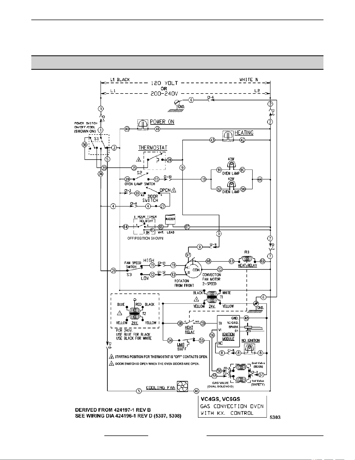
SCHEMATICS
VC4GS, VC6GS Mechanical (KX) Controls
VC4G & VC6G SERIES FULL SIZE CONVECTION OVENS - SCHEMATICS
F24682 Rev. J (0825) Page 54 of 86
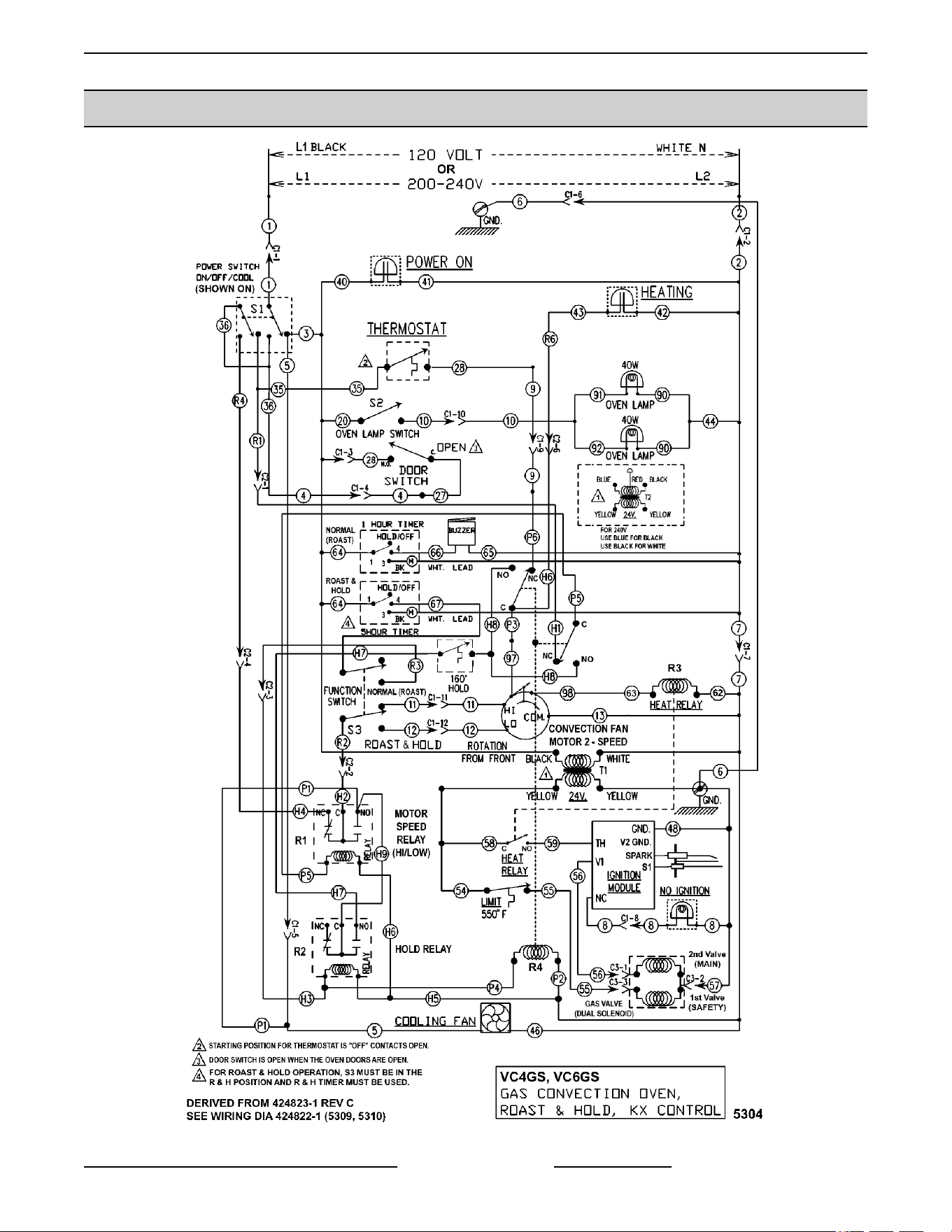
VC4GS, VC6GS Mechanical (KX) Controls, Roast & Hold Option
Fig. 99
VC4G & VC6G SERIES FULL SIZE CONVECTION OVENS - SCHEMATICS
Page 55 of 86 F24682 Rev. J (0825)

VC4GD, VC6GD Solid State Temperature Control
VC4GD & VC6GD Gas Convection Oven Solid State Control
BEFORE SERIAL NUMBER 481907145
VC4G & VC6G SERIES FULL SIZE CONVECTION OVENS - SCHEMATICS
F24682 Rev. J (0825) Page 56 of 86
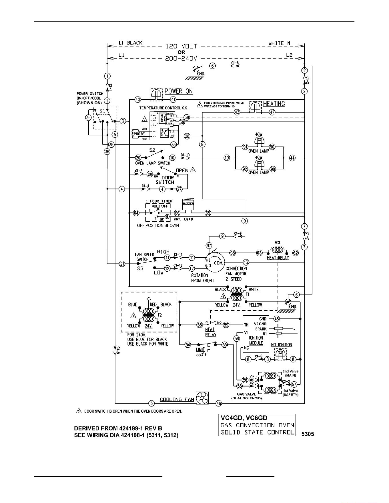
Fig. 100
VC4G & VC6G SERIES FULL SIZE CONVECTION OVENS - SCHEMATICS
Page 57 of 86 F24682 Rev. J (0825)

VC4 & 6GD-HGC-WKG Convec Oven with STD CNTLs - 120-240V - 00-424299-1D - AI4896 - STARTING
SERIAL NUMBER 481907146 - PDF Link
VC4 & 6GD-HGC-WKG Convec Oven with STD CNTLs - 120-240V - 00-424299-1D - AI4896
VC4G & VC6G SERIES FULL SIZE CONVECTION OVENS - SCHEMATICS
F24682 Rev. J (0825) Page 58 of 86
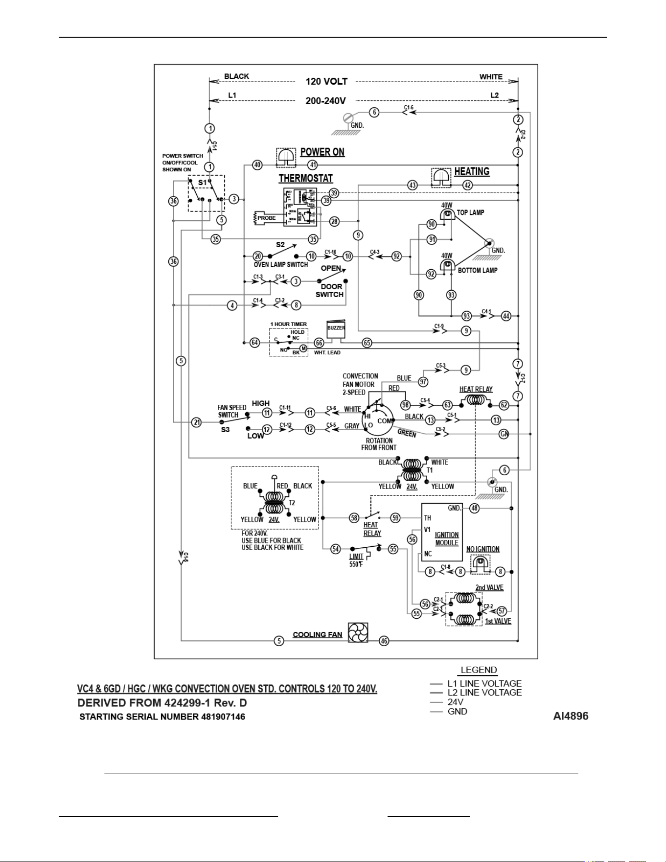
STARTING SERIAL NUMBER 481907146
8½ X 11 VC4 & 6GD Gas Convection Oven Solid State Control - 120-240V - 1Ph - 00-424199F - AI5735
STARTING AT SERIAL NUMBER 482080151
VC4G & VC6G SERIES FULL SIZE CONVECTION OVENS - SCHEMATICS
Page 59 of 86 F24682 Rev. J (0825)

VC4G & VC6G SERIES FULL SIZE CONVECTION OVENS - SCHEMATICS
F24682 Rev. J (0825) Page 60 of 86
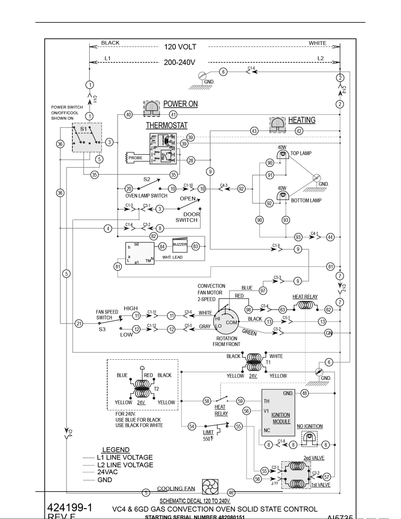
Fig. 102
VC4G & VC6G SERIES FULL SIZE CONVECTION OVENS - SCHEMATICS
Page 61 of 86 F24682 Rev. J (0825)
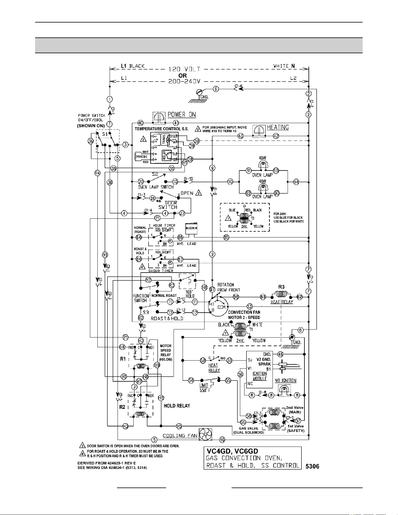
VC4GD, VC6GD Solid State Temperature Control, Roast & Hold Option
VC4G & VC6G SERIES FULL SIZE CONVECTION OVENS - SCHEMATICS
F24682 Rev. J (0825) Page 62 of 86
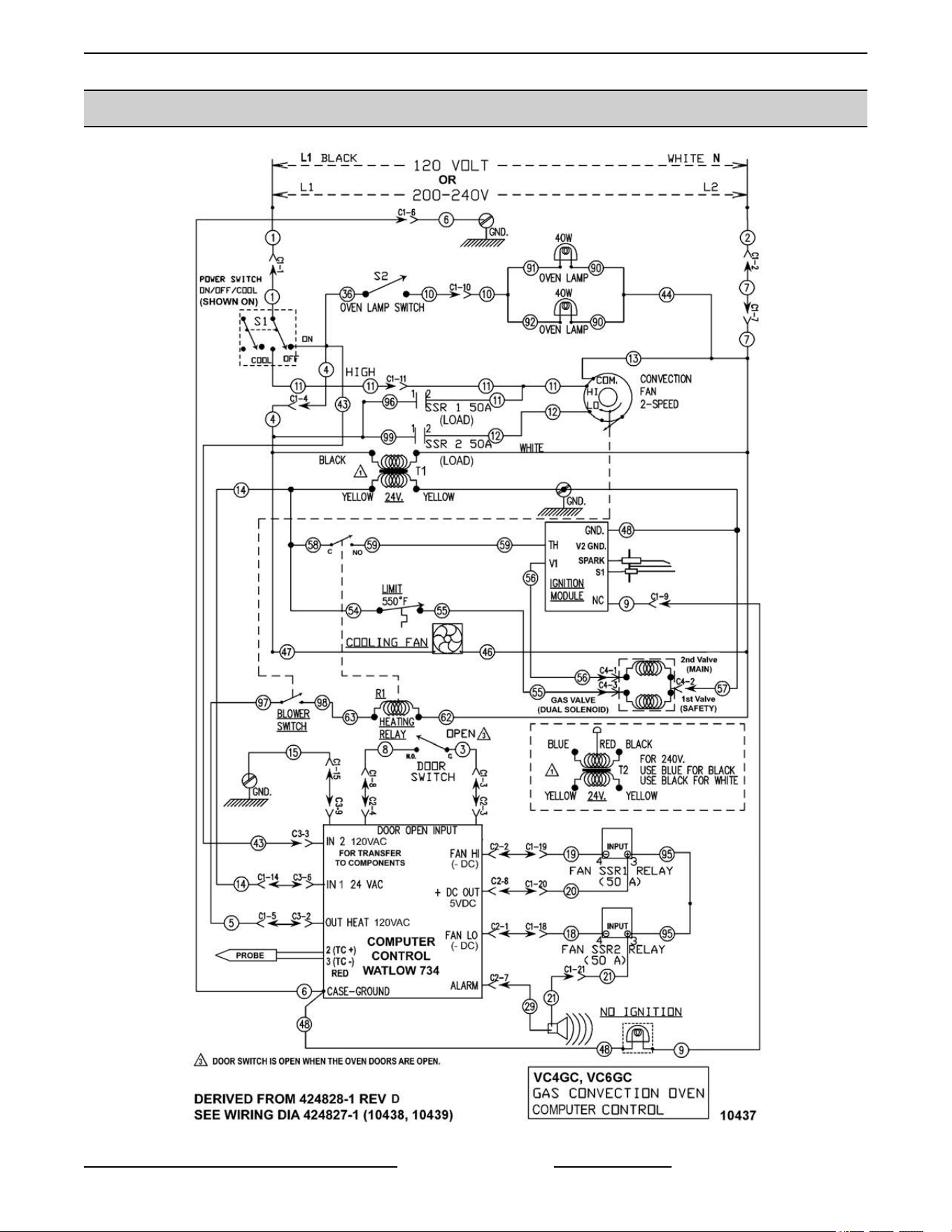
VC4GC, VC6GC Computer Control (Roast & Hold Standard)
UP TO SERIAL NUMBER 481907145
VC4G & VC6G SERIES FULL SIZE CONVECTION OVENS - SCHEMATICS
Page 63 of 86 F24682 Rev. J (0825)

VC4 & 6GD-HGC-WKGC Convection Oven Single Burner W/C 3700 - 120-240V - 00-959177C - AI4898 -
STARTING SERIAL NUMBER 481907146 (PDF Link)
• VC4 & 6GD-HGC-WKGC Convection Oven Single Burner wc 3700 - 120-240V - 00-959177C - AI4898
VC4G & VC6G SERIES FULL SIZE CONVECTION OVENS - SCHEMATICS
F24682 Rev. J (0825) Page 64 of 86
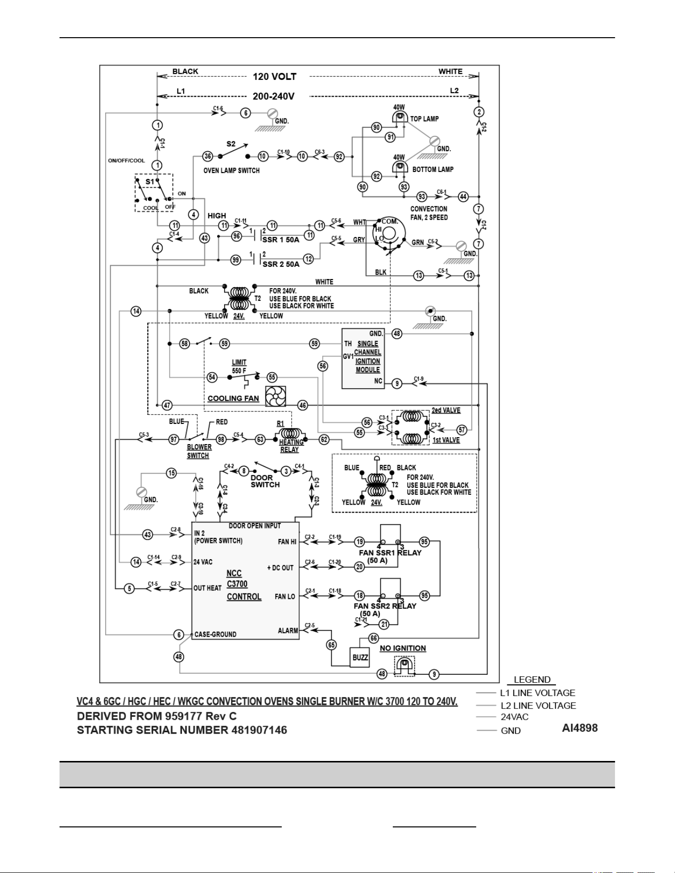
STARTING AT SERIAL NUMBER 481907146
VC4GD & VC6GD, VC With Standing Pilot 120 & 200 VOLT
VC4G & VC6G SERIES FULL SIZE CONVECTION OVENS - SCHEMATICS
Page 65 of 86 F24682 Rev. J (0825)
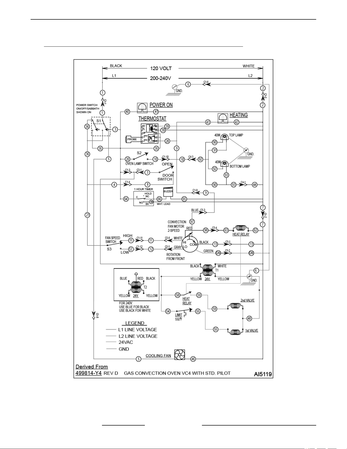
VC4GD & VC6GD with Standing Pilot - 120-240V - 00-499814-Y4 Rev D - AI5119 (PDF Link)
VC4GD & VC6GD w Standing Pilot - 120-240V - 00-499814-Y4 Rev D - AI5119
VC WITH STANDING PILOT VC4GD & VC6GD 120 & 200 VOLT
VC4G & VC6G SERIES FULL SIZE CONVECTION OVENS - SCHEMATICS
F24682 Rev. J (0825) Page 66 of 86
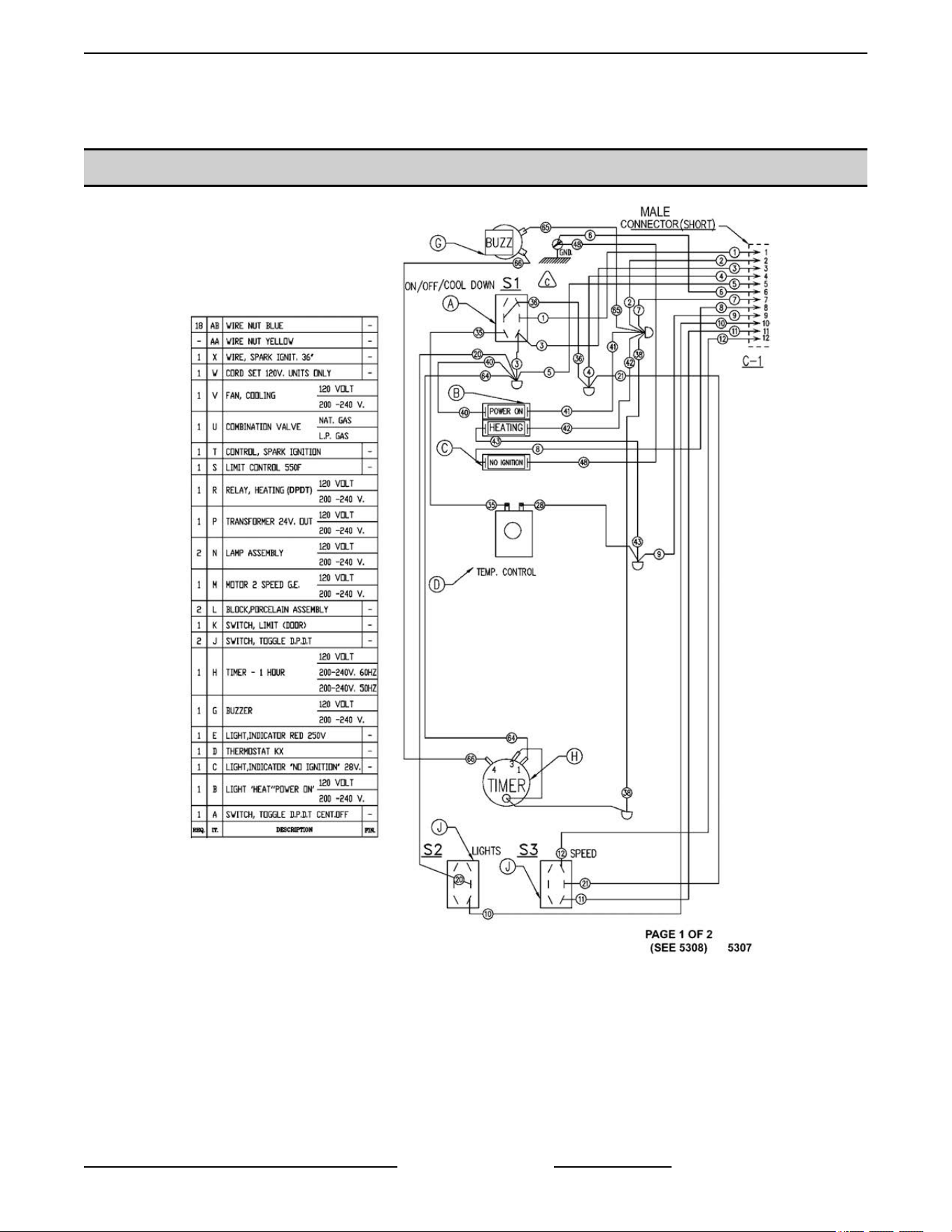
WIRING DIAGRAMS
VC4GS, VC6GS Mechanical (KX) Controls
Fig. 107
VC4G & VC6G SERIES FULL SIZE CONVECTION OVENS - WIRING DIAGRAMS
Page 67 of 86 F24682 Rev. J (0825)
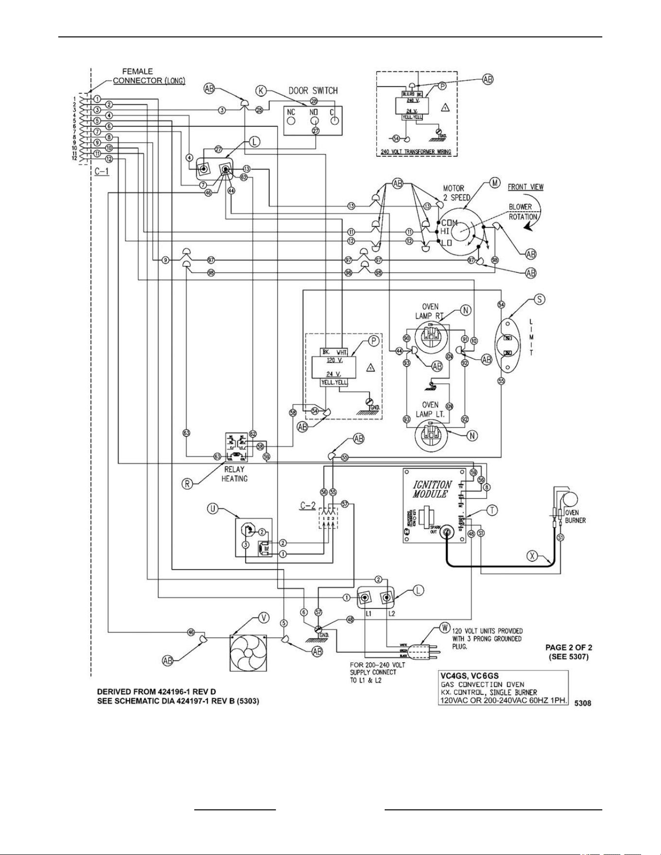
Fig. 108
VC4G & VC6G SERIES FULL SIZE CONVECTION OVENS - WIRING DIAGRAMS
F24682 Rev. J (0825) Page 68 of 86
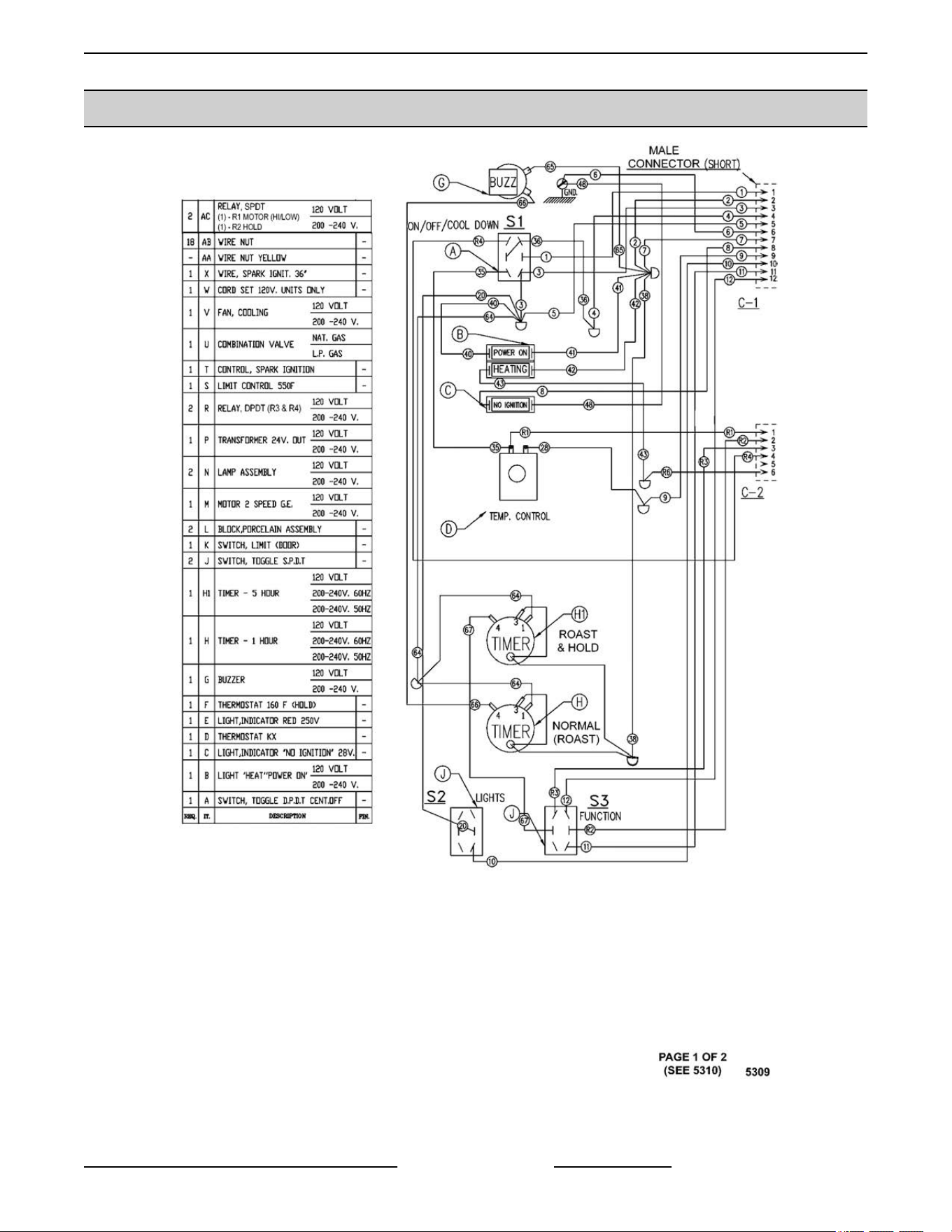
VC4GS, VC6GS Mechanical (KX) Controls, Roast & Hold Option
Fig. 109
VC4G & VC6G SERIES FULL SIZE CONVECTION OVENS - WIRING DIAGRAMS
Page 69 of 86 F24682 Rev. J (0825)
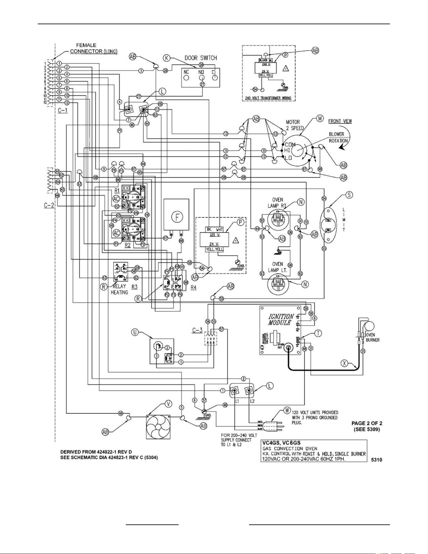
Fig. 110
VC4G & VC6G SERIES FULL SIZE CONVECTION OVENS - WIRING DIAGRAMS
F24682 Rev. J (0825) Page 70 of 86
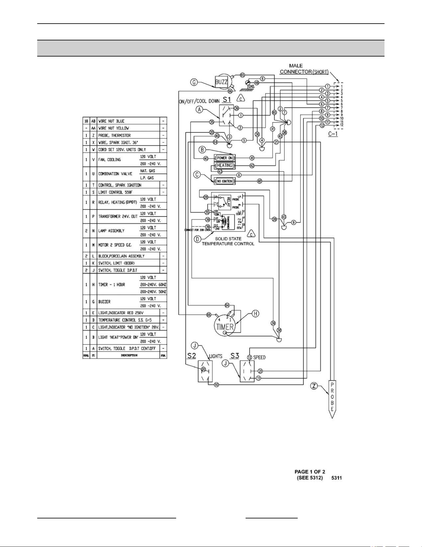
VC4GD, VC6GD Solid State Temperature Control
Fig. 111
VC4G & VC6G SERIES FULL SIZE CONVECTION OVENS - WIRING DIAGRAMS
Page 71 of 86 F24682 Rev. J (0825)
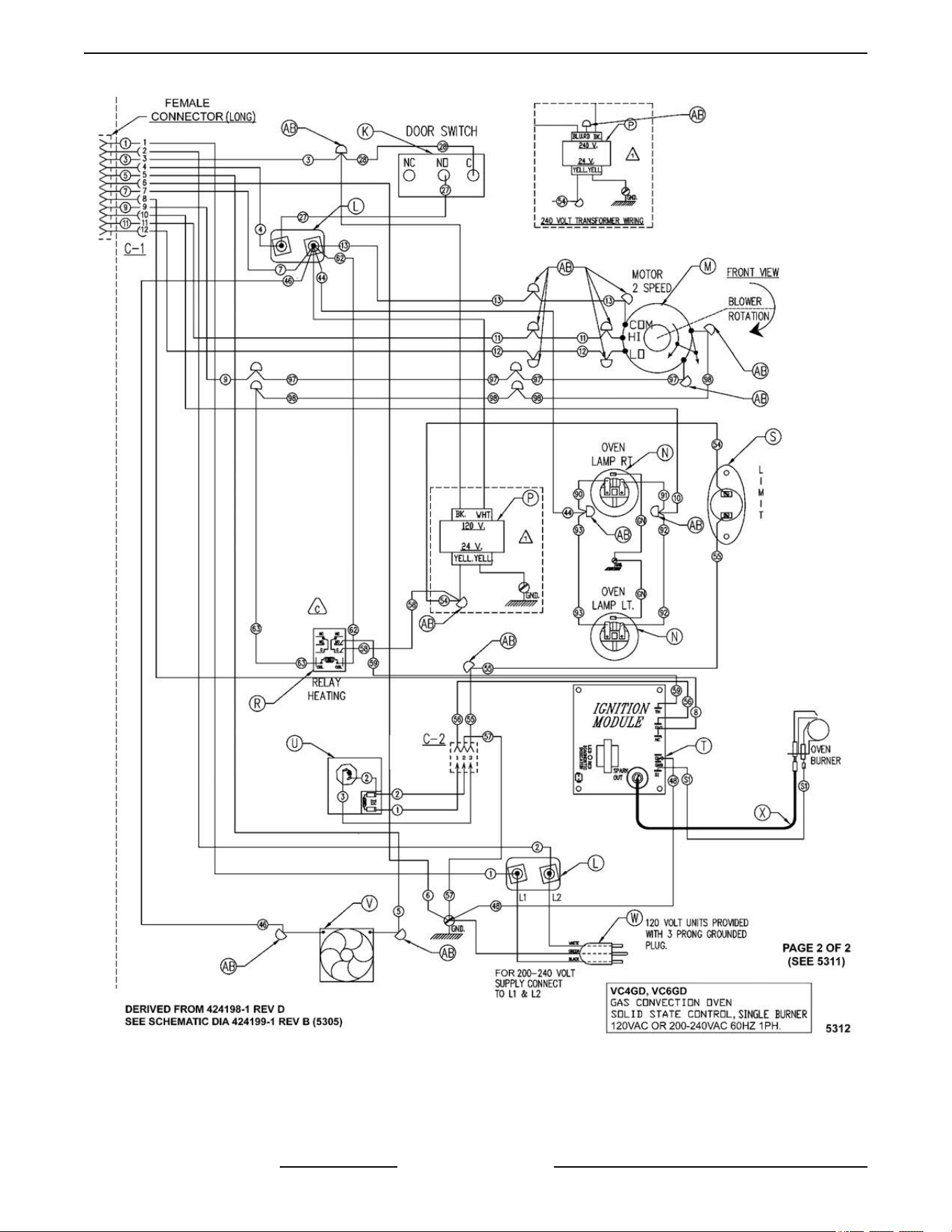
Fig. 112
VC4G & VC6G SERIES FULL SIZE CONVECTION OVENS - WIRING DIAGRAMS
F24682 Rev. J (0825) Page 72 of 86
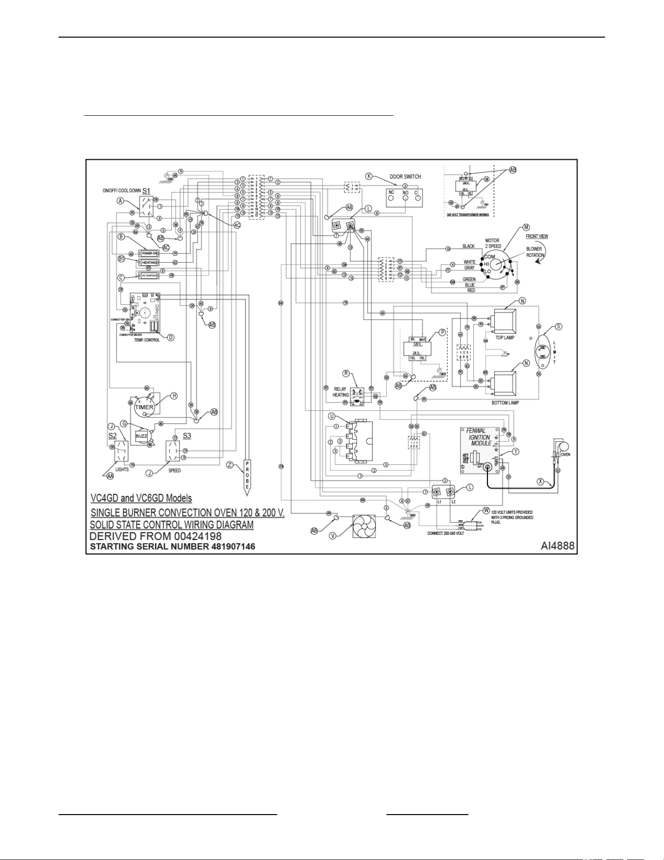
VC4GD & V6GD Single Burner with Solid State Control - 120-200V - 00-424198 (PDF Link) Starting Serial
Number 48190746
VC4GD-VC6GD Single Burner - 120-200V - 00-424198 - AI4888
STARTING AT SERIAL NUMBER 481907146
Fig. 113
VC4G & VC6G SERIES FULL SIZE CONVECTION OVENS - WIRING DIAGRAMS
Page 73 of 86 F24682 Rev. J (0825)
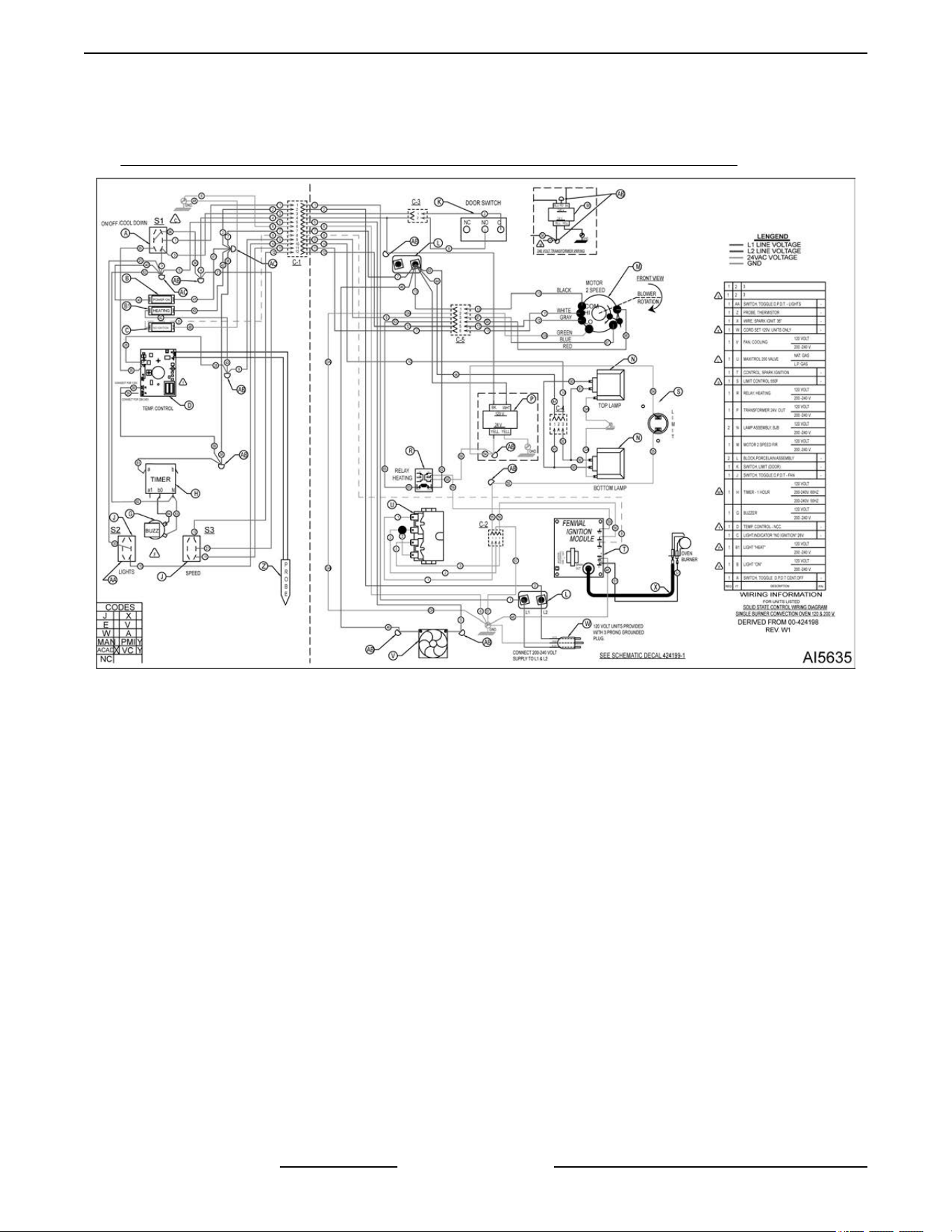
VC4GD & V6GD Single Burner Solid State Control - 00-424198W1 - AI5635 Starting Serial Number 482080151
(PDF Link)
Single Burner Convection Oven - 120-200VAC - 50 & 60Hz - 1PH - 00-424198W - AI5635
Fig. 114
VC4G & VC6G SERIES FULL SIZE CONVECTION OVENS - WIRING DIAGRAMS
F24682 Rev. J (0825) Page 74 of 86
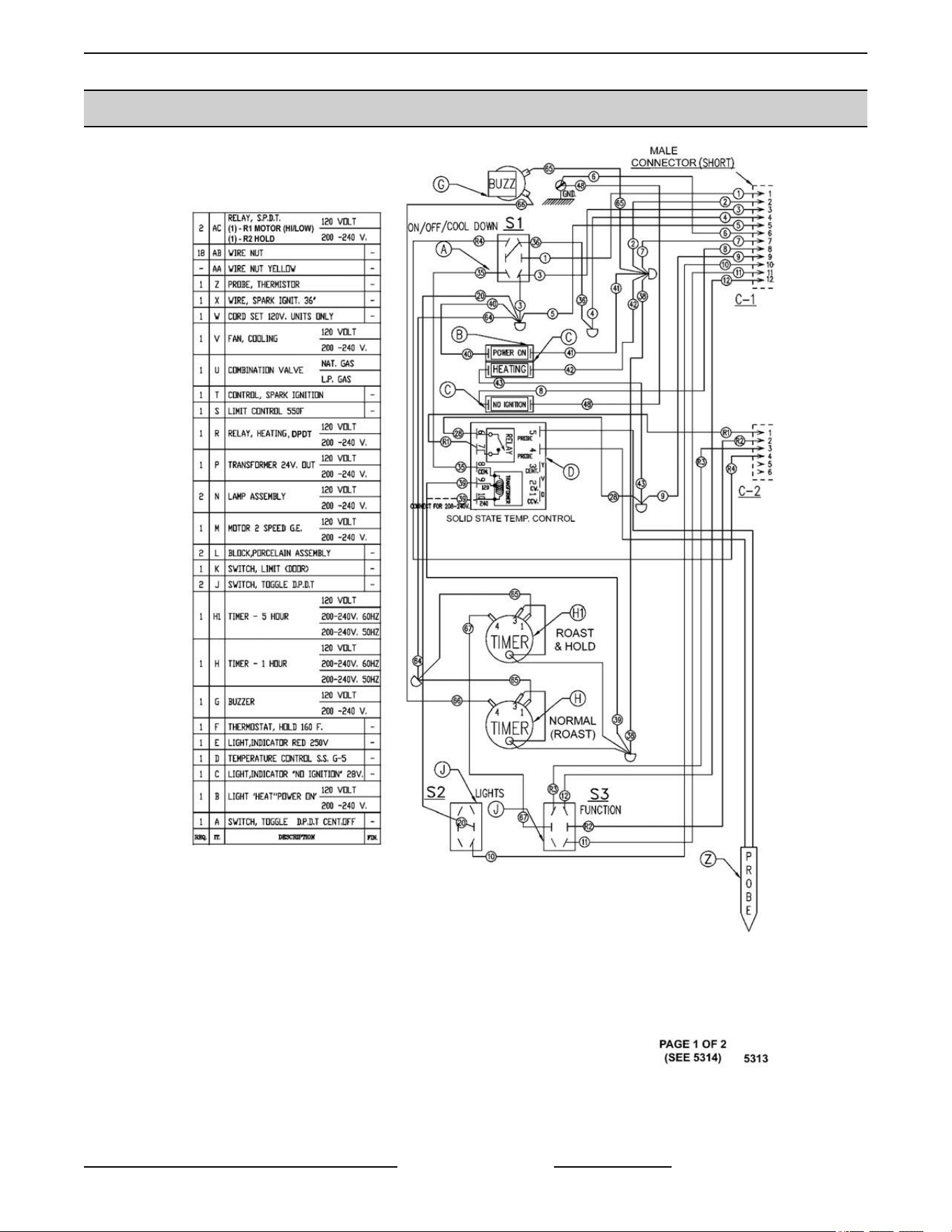
VC4GD, VC6GD Solid State Temperature Control, Roast & Hold Option
Fig. 115
VC4G & VC6G SERIES FULL SIZE CONVECTION OVENS - WIRING DIAGRAMS
Page 75 of 86 F24682 Rev. J (0825)
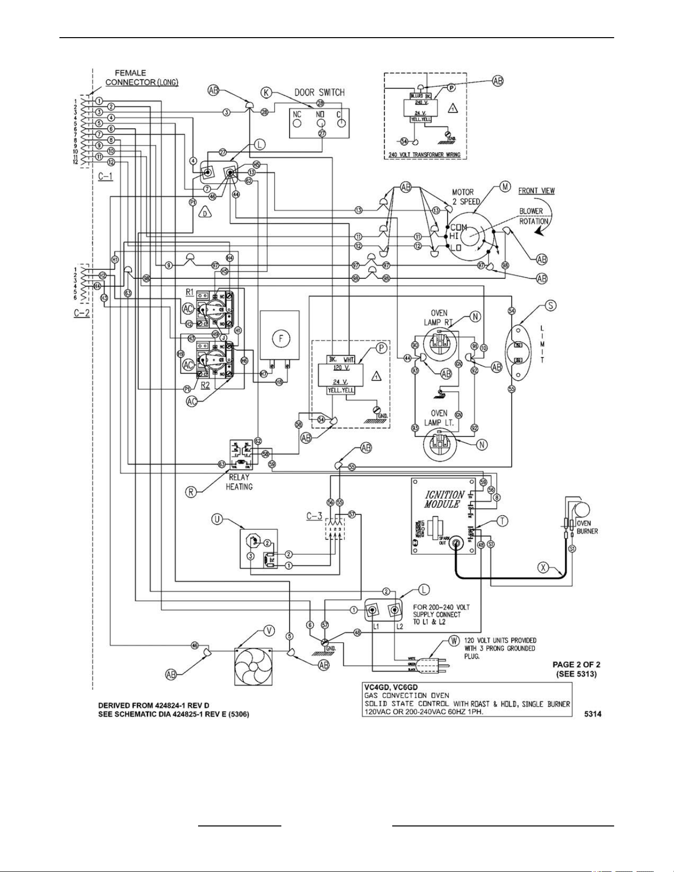
Fig. 116
VC4G & VC6G SERIES FULL SIZE CONVECTION OVENS - WIRING DIAGRAMS
F24682 Rev. J (0825) Page 76 of 86
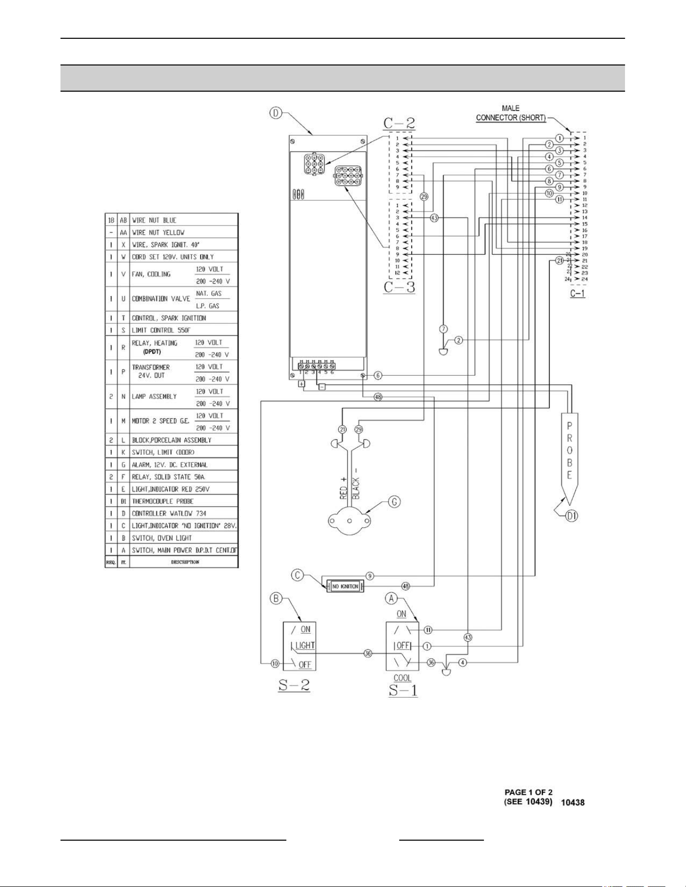
VC4GC, VC6GC Computer Control (Roast & Hold Standard)
Fig. 117
VC4G & VC6G SERIES FULL SIZE CONVECTION OVENS - WIRING DIAGRAMS
Page 77 of 86 F24682 Rev. J (0825)
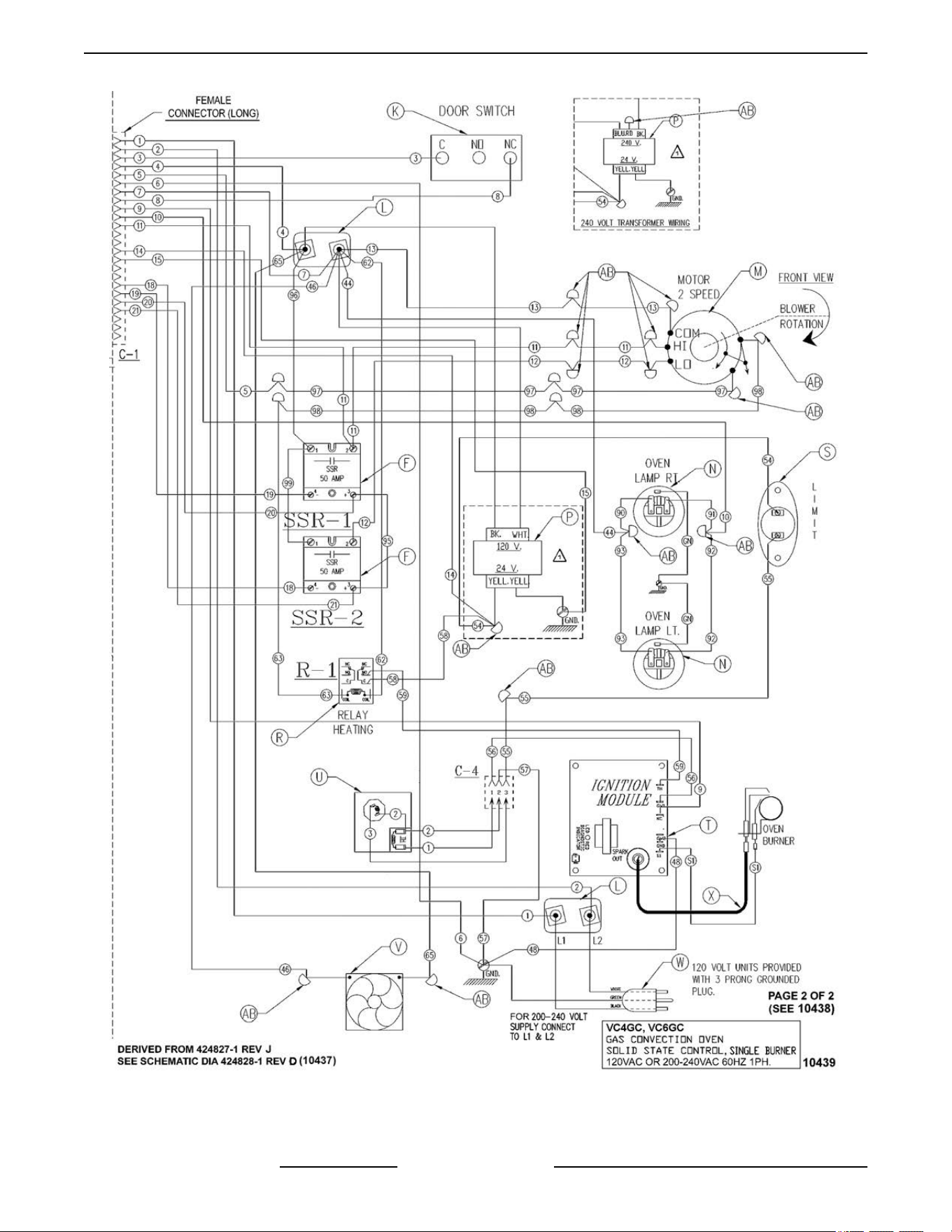
Fig. 118
VC4G & VC6G SERIES FULL SIZE CONVECTION OVENS - WIRING DIAGRAMS
F24682 Rev. J (0825) Page 78 of 86
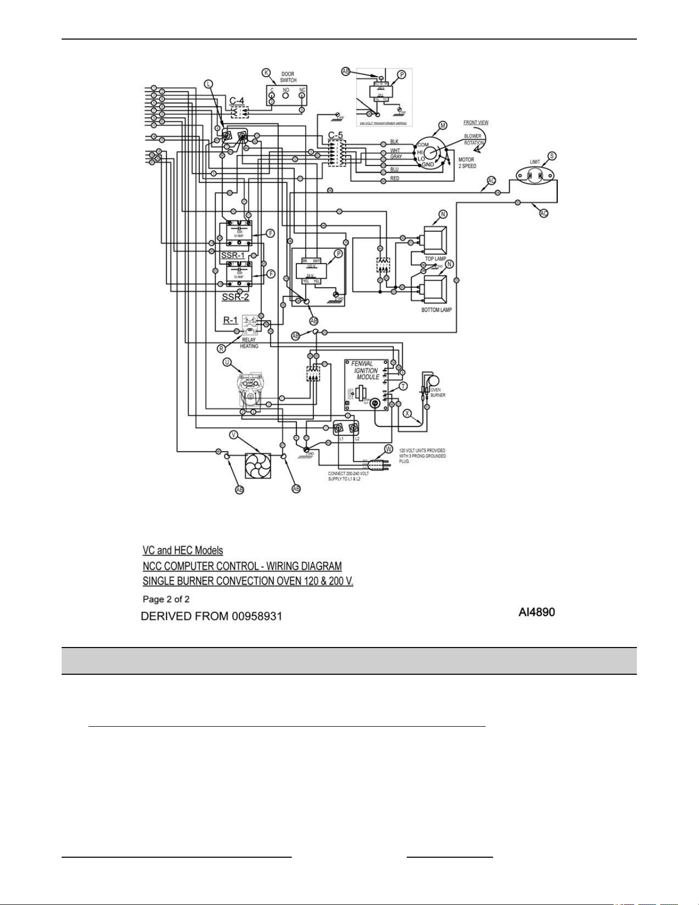
STARTING AT SERIAL NUMBER 481907146
VC4GD & VC6GD, VC With Standing Pilot 120 & 200 VOLT
VC4GD & VC6GD, VC With Standing Pilot 120 & 200 VOLT - 00-499814-Y4 - AI4955 (PDF Link)
VC4GD & VC6GD VC with Standing Pilot - 120-200V - 00-499814-Y4 - AI4955
VC WITH STANDING PILOT VC4GD & VC6GD 120 & 200 VOLT
VC4G & VC6G SERIES FULL SIZE CONVECTION OVENS - WIRING DIAGRAMS
Page 79 of 86 F24682 Rev. J (0825)
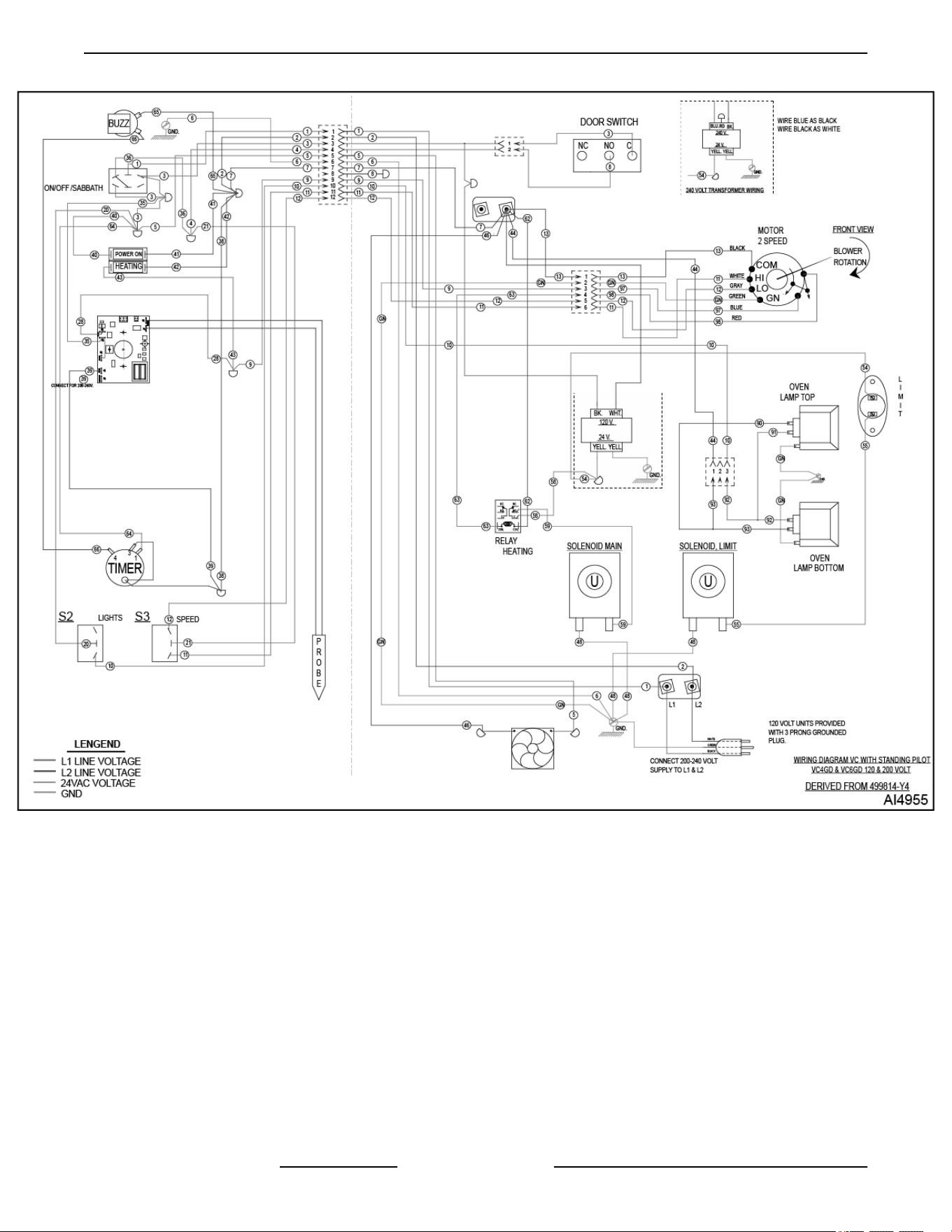
Fig. 120
VC4G & VC6G SERIES FULL SIZE CONVECTION OVENS - WIRING DIAGRAMS
F24682 Rev. J (0825) Page 80 of 86
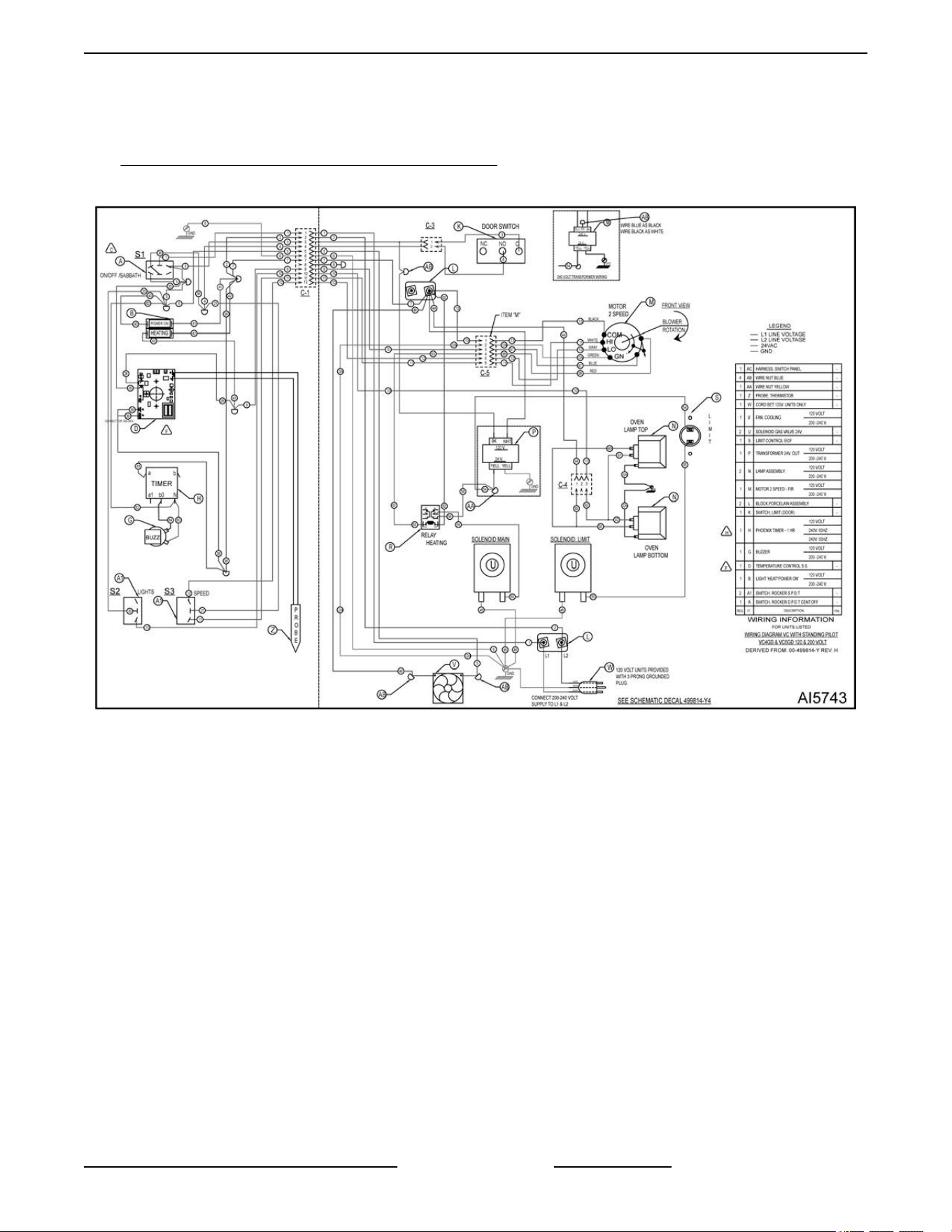
VC4GD & VC6GD, VC With Standing Pilot 120 & 200 VOLT - 00-499814-Y-H - AI5743 Starting Serial Number
482080151 (PDF Link)
VC4GD & VC6GD - 120-200V - 0099814-Y-H - AI5743
STARTING AT SERIAL NUMBER 482080151
Fig. 121
VC4G & VC6G SERIES FULL SIZE CONVECTION OVENS - WIRING DIAGRAMS
Page 81 of 86 F24682 Rev. J (0825)
TROUBLESHOOTING
Certain procedures in this section require electrical test or measurements while power is
applied
to the machine. Exercise extreme caution at all times and follow Arc Flash procedures.
If test points are not easily accessible, disconnect power and follow Lockout/Tagout
procedures, attach test equipment and reapply power to test.
ALL MODELS
SYMPTOMS POSSIBLE CAUSES
Blower motor doesn’t run with 1S in “Cool Down” or “On”
position.
1. Line voltage.
2.
Power switch (S1) malfunction.
3. Switch (S3) malfunction.
4. Interconnecting wiring malfunction.
5. Motor inoperable.
Blower motor doesn’t run in “On” position. “Cool Down”
functions OK.
1. Door switch malfunction.
2.
Power switch contacts inoperative.
3. Interconnecting wiring malfunction.
Blower motor doesn’t run in “Cool Down” position. Runs
OK in “On” position.
1. Power switch malfunction.
2.
Interconnecting wiring malfunction.
Gas does not ignite; No spark; No Ignition Light ON.
1. Shorted electrode on ignitor/flame sense.
2.
Ignitor cable (high voltage) OPEN.
3. Heat relay (R3) malfunction.
4. Transformer (T1) inoperative.
5. High limit thermostat open.
6. Interconnecting wiring malfunction.
7. Ignition Module malfunction.
Sparks but gas does not ignite.
1. Gas solenoid valve OFF or inoperative.
2.
Manual gas valve CLOSED.
3. Gas supply OFF or Insufficient gas pressure.
4. Interconnecting wiring malfunction.
5. Ignition Module malfunction.
VC4G & VC6G SERIES FULL SIZE CONVECTION OVENS - TROUBLESHOOTING
F24682 Rev. J (0825) Page 82 of 86
SYMPTOMS POSSIBLE CAUSES
Gas ignites but will not maintain flame.
1. Igniter lead connections malfunction.
2.
Ignitor ground inoperative.
3. Ignitor/flame sense malfunction.
4. Insufficient gas pressure.
5. Snorkel vent plugged, obstructed or missing.
6. Incorrect polarity from transformer (T1) to Ignition
module.
Excessive or low heat.
1. Temperature probe malfunction on models
HGC5/5X. (Thermostat malfunction on models
DGC5)
2.
Temperature control board malfunction.
3. Gas pressure Insufficient.
4. Gas orifice plugged or obstructed.
Mechanical Timer inoperative or not functioning properly.
1. Interconnecting wiring malfunction.
2.
Line voltage incorrect.
3. Timer malfunction.
Cook mode OK, no Hold mode. (Cook & Hold models
only).
1. Cook and Hold switch (S3) malfunction.
2.
R2 hold relay malfunction.
3. Cook & Hold timer malfunction.
4. Interconnecting wiring malfunction.
Component cooling Fan does not run.
1. Motor inoperable.
2.
Interconnecting wiring malfunction.
Uneven Cooking.
1. Convection Fan motor speed/direction.
2.
Poor combustion.
A. Gas pressure incorrect.
B. Exhaust vent plugged or obstructed.
C. Snorkel Vent plugged or obstructed.
3. Air flow Baffles missing or damaged.
Intermittent problems.
1. High ambient temperatures.
2.
Wiring connections loose.
3. Cooling fan malfunction.
No power to temperature control.
1. Power switch (S1) in “Cool Down”.
2.
Door or door switch open.
IGNITION MODULE DIAGNOSTICS
VC4G & VC6G SERIES FULL SIZE CONVECTION OVENS - TROUBLESHOOTING
Page 83 of 86 F24682 Rev. J (0825)
NUMBER OF LED FLASHES INDICATES POSSIBLE CAUSE
2 Flashes Burner flame with no call for heat.
1. Main gas valve stuck open,
burner on with no call for heat
from the temperature control
system. Replace main gas
valve.
2.
Check flame sensor and sensor
wire.
3. Ignition module malfunction.
3 Flashes Ignition system has locked out.
1. Ignition module could not
“Prove”
flame after three tries for
ignition within the lockout time
timing provided.
A. Check for gas supply to
burner.
B. Check for spark to ignition
electrode.
1) Check spark gap (gap
should be 1/8").
C. Check ignition cable for
continuity.
D. Check for flame current in
flame sense wire (0.000001
Amp Min. DC) using FC
designated terminals.
1) Check burner
adjustment (air/gas).
NOTE: If A thru D check
out, replace ignition
module.
4 Flashes Internal board problem.
1. Ignition module malfunction.
Remove
power from “R” terminal
for five seconds then reconnect.
If fault remains, replace ignition
module.
COMPUTER CONTROL MODELS ONLY
SYMPTOM POSSIBLE CAUSES
Oven does not heat.
1. High limit switch open.
2.
Probe malfunction.
3. Control malfunction.
High limit thermostat shutting off gas burner.
1. Probe malfunction.
2.
Control malfunction.
VC4G & VC6G SERIES FULL SIZE CONVECTION OVENS - TROUBLESHOOTING
F24682 Rev. J (0825) Page 84 of 86
SYMPTOM POSSIBLE CAUSES
Oven not hot enough.
1. Probe malfunction.
2.
Control range high (rH1) setting to low.
SETUP
MODE under COMPUTER CONTROL (VC4GD,
VC6GD).
3.
Control malfunction.
Error Codes
In the display window, the error code will alternate between the code and the oven cavity temperature or dashes if
the
oven is calling for heat (heat light on). When the condition causing the error is resolved, normal oven operation
can resume.
NOTE: To check a "Setup Parameter" and its corresponding "Data Value", see
"SETUP MODE" under COMPUTER
CONTROL (VC4GC/6GC).
NOTE:
If the cause of the error is not apparent, check for these conditions as they may also cause errors to occur:
Electrical noise or a noise event, excess environmental moisture or temperature, or vibration.
CODE & PROBLEM
PROBABLE CAUSE SOLUTION
Er01 - ROM checksum error Internal ROM malfunction Cycle power
Er02 - RAM checksum error Internal RAM malfunction Cycle power
Er03 - Ambient sensor error Ambient temperature is below 32°F
Check ambient temperature at the
control.
Er04 - Configuration error Microprocessor malfunction Cycle power
Er05 - EPROM error Power loss while storing data Cycle power
Er06 - Zone 1 A/D underflow error
• Incorrect sensor type
•
Measuring temperature outside
the sensor range
• Check the InP1 setup
parameter. Verify it matches
your sensor.
•
Check sensor and connections
for a reversed or open sensor. If
the condition causing the error is
resolved, the error will clear.
Er07 - Zone 1 A/D overflow error Open sensor
• Check the InP1 setup
parameter. Verify it matches
your sensor.
•
Check sensor and connections
for a reversed or open sensor. If
the condition causing the error is
resolved, the error will clear.
Er10 - Stack overflow error Microprocessor malfunction
• Cycle power
•
Check sensor and connections
for a reversed or open sensor
VC4G & VC6G SERIES FULL SIZE CONVECTION OVENS - TROUBLESHOOTING
Page 85 of 86 F24682 Rev. J (0825)
CODE & PROBLEM PROBABLE CAUSE SOLUTION
Er11 - Open sensor error Open sensor
• Check the InP1 setup
parameter. Verify it matches
your sensor.
•
Check sensor and connections
for a reversed or open sensor. If
the condition causing the error is
resolved, the error will clear.
Er12 - Shorted sensor
• Incorrect sensor type
•
Measuring temperature outside
the sensor range
• Check the InP1 setup
parameter. Verify it matches
your sensor.
•
Check sensor and connections
for a reversed or open sensor. If
the condition causing the error is
resolved, the error will clear.
MECHANICAL CONTROLS TROUBLESHOOTING
VC Mechanical Controls Troubleshooting
VC4G & VC6G SERIES FULL SIZE CONVECTION OVENS - TROUBLESHOOTING
F24682 Rev. J (0825) Page 86 of 86
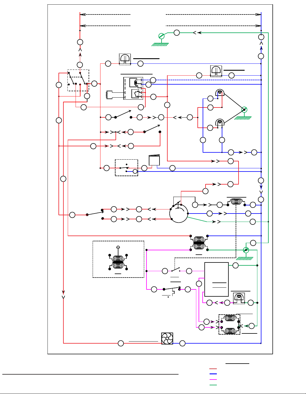
AI4896
DERIVED FROM 424299-1 Rev. D
VC4 & 6GD / HGC / WKG CONVECTION OVEN STD. CONTROLS 120 TO 240V.
BLACK
WHITE
POWER SWITCH
OVEN LAMP SWITCH
HIGH
LOW
FAN SPEED
SWITCH
COOLING FAN
OPEN
DOOR
SWITCH
S3
S2
S1
120 VOLT
200-240V
L1
L2
GND.
C1-2
C1-7
44
40W
40W
C1-1
20 10
C1-10
92
3
8
C1-4
6
465
91
90
92
TOP LAMP
BOTTOM LAMP
5
C1-5
9
9
11
12
11
12
COM.
HI
LO
CONVECTION
FAN MOTOR
2-SPEED
13
7
BLACK WHITE
FOR 240V.
USE BLUE FOR BLACK
USE BLACK FOR WHITE
24V.
GND.
YELLOWYELLOW
54
HEAT
RELAY
LIMIT
550 F
IGNITION
MODULE
V1
2nd VALVE
T1
NC
57
C1-8
BLACK
T2
24V.
YELLOW
BLUE
YELLOW
RED
8
GND. 48
58 59 TH
1st VALVE
C2-2
C2-1
C2-3
55
56
56
55
ON/OFF/COOL
SHOWN ON
35
POWER ON
THERMOSTAT
7
HEATING
ROTATION
FROM FRONT
4
97
98
21
63 62
NO
1 HOUR TIMER
WHT. LEAD
BUZZER
65
66
HOLD
NC
BK
M
64
C
C1-3
28
HEAT RELAY
8 8
NO IGNITION
C1-6
6
O
V
Y
CCW.
CW.
CENT.
PROBE
COM.
120
240
PROBE
RELAY
TRANSFORMER
6 7 8 9
10
12345
39
35
PROBE
9
10
C4-1
93
93
90
GND.
C5-4
C5-1
C5-3
5
C5-6
C5-5
13
BLACK
RED
GRAY
WHITE
GREEN
C5-2
GN
BLUE
C1-9
C1-11
C1-12
2
2
1
36
1
3
40 41
43 42
C3-1
C3-2
C4-3
36
39
STARTING SERIAL NUMBER 481907146
LEGEND
L1 LINE VOLTAGE
L2 LINE VOLTAGE
24V
GND
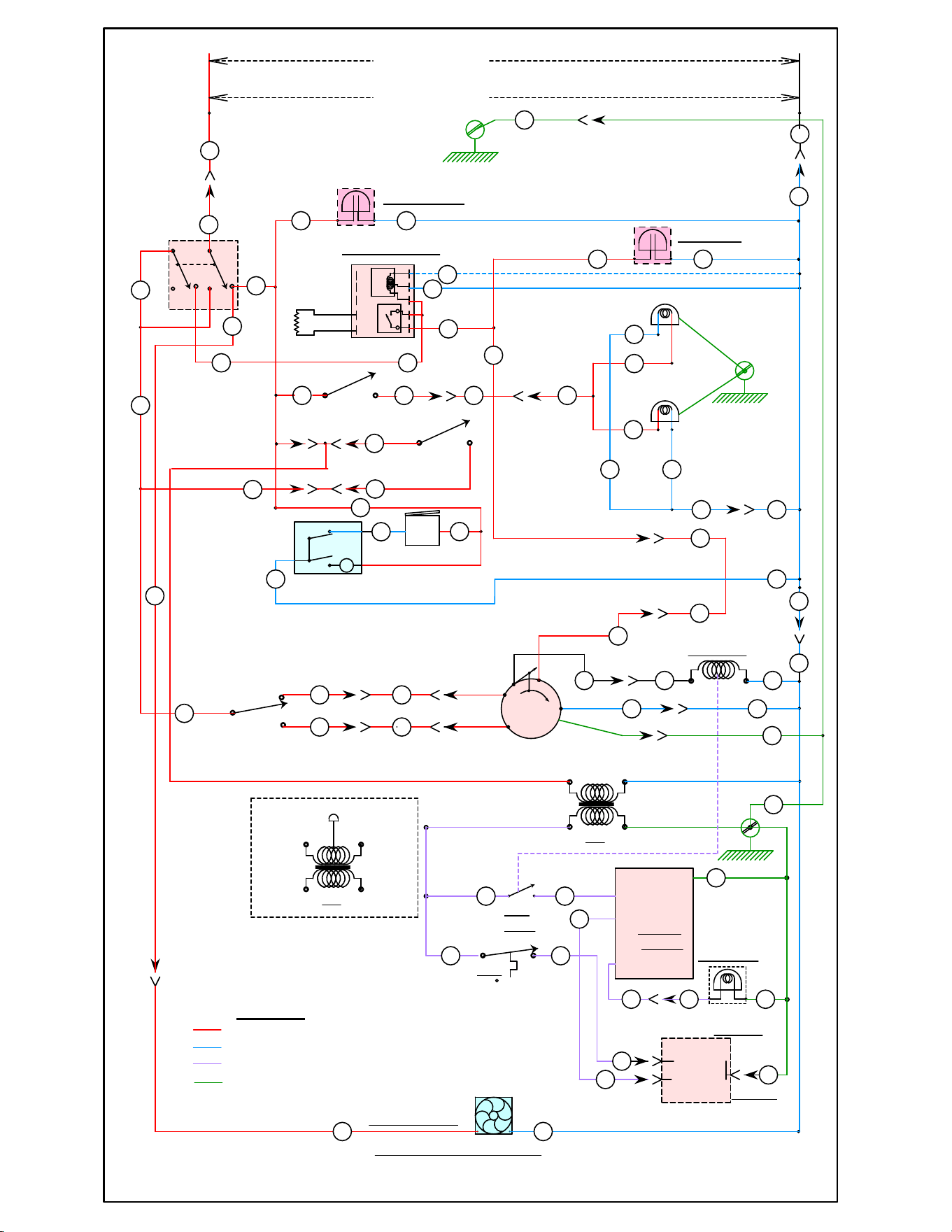
LEGEND
GND.
2
2
1
36
1
SCHEMATIC DECAL 120 TO 240V.
GND.
3
40 41
43 42
O
V
Y
CCW.
CW.
CENT.
PROBE
COM.
120
240
PROBE
RELAY
TRANSFORMER
6 7 8 9 10
12345
C3-1
C3-2
C4-3
GND.
36
AI5735
BLACK
WHITE
POWER SWITCH
OVEN LAMP SWITCH
HIGH
LOW
FAN SPEED
SWITCH
COOLING FAN
OPEN
424199-1
VC4 & 6GD GAS CONVECTION OVEN SOLID STATE CONTROL
DOOR
SWITCH
S3
S2
S1
120 VOLT
200-240V
L1
L2
REV F
C1-2
C1-7
44
40W
40W
C1-1
20 10
C1-10
92
3
8
C1-4
6
465
91
90
92
TOP LAMP
BOTTOM LAMP
5
C1-5
9
9
11
12
11
12
COM.
HI
LO
CONVECTION
FAN MOTOR
2-SPEED
13
7
BLACK WHITE
FOR 240V.
USE BLUE FOR BLACK
USE BLACK FOR WHITE
24V.
YELLOWYELLOW
54
HEAT
RELAY
LIMIT
550 F
IGNITION
MODULE
V1
2ed VALVE
T1
NC
57
C1-8
BLACK
T2
24V.
YELLOW
BLUE
YELLOW
RED
8
GND. 48
58 59 TH
1st VALVE
C2-2
C2-1
55
56
55
56
ON/OFF/COOL
SHOWN ON
35
39
POWER ON
THERMOSTAT
7
HEATING
ROTATION
FROM FRONT
4
97
98
21
63 62
WHT. LEAD
BUZZER
83
84
82
C1-3
28
HEAT RELAY
8 8
NO IGNITION
C1-6
6
39
35
PROBE
9
10
C4-1
93
93
90
C5-4
C5-1
C5-3
5
C5-6
C5-5
13
BLACK
RED
GRAY
WHITE
GREEN
C5-2
GN
BLUE
C1-9
C1-11
C1-12
J-??
a
b
TM
b0
a1
N
L
8181
L1 LINE VOLTAGE
L2 LINE VOLTAGE
24VAC
GND
STARTING SERIAL NUMBER 482080151
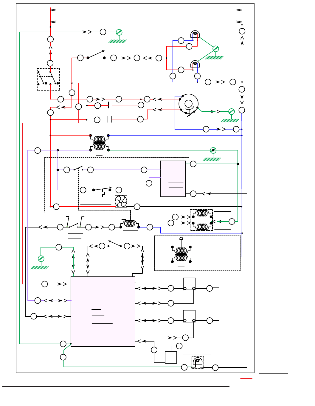
AI4898
DERIVED FROM 959177 Rev C
VC4 & 6GC / HGC / HEC / WKGC CONVECTION OVENS SINGLE BURNER W/C 3700 120 TO 240V.
BLACK
WHITE
ON/OFF/COOL
OVEN LAMP SWITCH
HIGH
COOLING FAN
DOOR OPEN INPUT
OUT HEAT
FAN SSR1 RELAY
(50 A)
FAN SSR2 RELAY
(50 A)
4
3
IN 2
(POWER SWITCH)
NCC
C3700
CONTROL
CASE-GROUND
- +
+
DOOR
SWITCH
S1
120 VOLT
200-240V
L1
L2
GND.
C1-2
C1-7
40W
40W
C1-1
C2-8
FAN LO
24 VAC
C2-2
C2-1
4
-
3
C1-19
C1-18
C1-6
C2-10C1-15
C2-4C1-8
C2-3C1-3
TOP LAMP
BOTTOM LAMP
C1-11
COM.
HI
LO
CONVECTION
FAN, 2 SPEED
BLACK
WHITE
FOR 240V.
USE BLUE FOR BLACK
USE BLACK FOR WHITE
24V.
GND.
YELLOWYELLOW
LIMIT
550 F
IGNITION
MODULE
GV1
2ed VALVE
T2
NC
C1-9
BLACK
T2
24V.
YELLOW
BLUE
YELLOW
FOR 240V.
USE BLUE FOR BLACK
USE BLACK FOR WHITE
RED
SINGLE
CHANNEL
GND.
TH
1st VALVE
C3-2
ON
OFF
COOL
SSR 1 50A
SSR 2 50A
21
21
BLOWER
SWITCH
HEATING
RELAY
R1
C2-7
C1-5
C1-20
C2-6
C1-21
C2-5
ALARM
FAN HI
+ DC OUT
NO IGNITION
C2-9
C1-14
GND.
C4-2
BUZZ
C6-1
S2
C1-10
C5-4
BLUE
RED
GND.
C5-1
BLK
GRY
WHT
GND.
GRN
C5-2
C5-3
2
7
44
1
1
43
95
95
19
18
6
4647
90
91
92
93
4
11 11
13
7
54
57
9
48
58 5959
C3-1
C3-3
55
56
56
55
11
4
C1-4
11
96
99
11
12
9897
63 62
5
6
8
3
20
21
66
65
48
48
9
43
14
14
15
C4-1
93
36 10 10
C6-3
92
90
13
C5-6
C5-5
STARTING SERIAL NUMBER 481907146
LEGEND
L1 LINE VOLTAGE
L2 LINE VOLTAGE
24VAC
GND
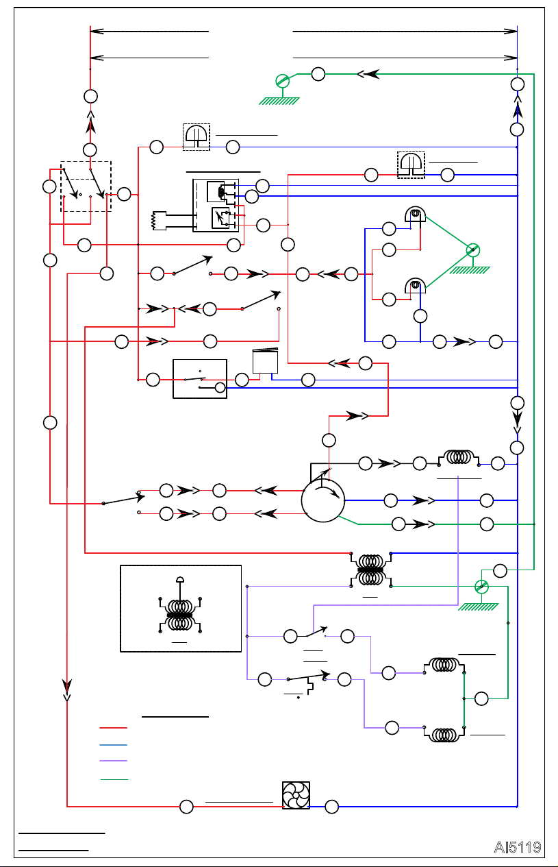
AI5119
2
2
1
36
1
3
40 41
43 42
C3-1
C4-3
BLACK
WHITE
POWER SWITCH
OVEN LAMP SWITCH
HIGH
LOW
FAN SPEED
SWITCH
COOLING FAN
OPEN
Derived From
499814-Y4
DOOR
SWITCH
S3
S2
S1
120 VOLT
200-240V
L1
L2
REV D
GND.
C1-2
C1-7
44
40W
40W
C1-1
20 10
C1-10
10
3
8
C1-4
6
465
90
92
93
TOP LAMP
BOTTOM LAMP
5
C1-5
9
C1-9
11
12
C1-11
11
C1-12
12
COM.
HI
LO
CONVECTION
FAN MOTOR
2-SPEED
13
7
BLACK WHITE
FOR 240V.
USE BLUE FOR BLACK
USE BLACK FOR WHITE
24V.
GND.
YELLOWYELLOW
54
HEAT
RELAY
LIMIT
550 F
2nd VALVE
T1
48
BLACK
T2
24V.
YELLOW
BLUE
YELLOW
RED
58 59
1st VALVE
55
59
55
ON/OFF/SABBATH
SHOWN ON
35
39
POWER ON
THERMOSTAT
7
HEATING
ROTATION
FROM FRONT
4
97
98
21
36
63 62
NO
1 HOUR TIMER
WHT. LEAD
BUZZER
65
66
HOLD
NC
BK
M
64
C
C1-3
28
HEAT RELAY
C1-6
6
O
V
Y
CCW.
CW.
CENT.
PROBE
COM.
120
240
PROBE
RELAY TRANSFORMER
6 7 8 9 10
12345
39
35
PROBE
9
GAS CONVECTION OVEN VC4 WITH STD. PILOT
92
91
93
C4-1
90
GND.
C5-4
C5-3
C5-6
C5-5
BLACK
RED
BLUE
WHITE
GRAY
C5-1
13
C5-2
GREEN
GN
GN
LEGEND
L1 LINE VOLTAGE
L2 LINE VOLTAGE
24VAC
GND
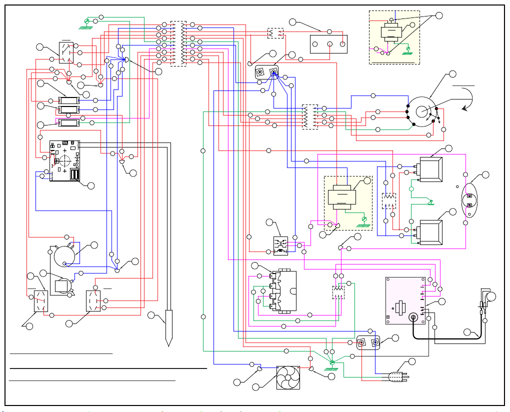
WHITE
BLACK
GREEN
3
2
1
92
91
90
93
48
48
6
7
13
44
46
54
54
5
9
RD
BK.
BLU.
240 V.
24 V.
YEL
YEL
54
97
98
5556
55
56
57
59
57
59
58
58
62
62
63
55
3
1
2
58
8
8
46
13
11
98
63
63
12
11
12
10
9
5
11
2
6
7
6
64
39
38
66
65
48
7
43
38
48
64
10
40
3
20
11
5
21
12
41
42
35
4
3
1
36
2
9
5
10
12
11
6
8
7
9
4
2
3
20
21
36
65
8
66
28
40
42
43
8
41
39
35
39
10
44
44
92
93
GN
GN
2
2
3
28
AI4888
DERIVED FROM 00424198
SINGLE BURNER CONVECTION OVEN 120 & 200 V.
VC4GD and VC6GD Models
SOLID STATE CONTROL WIRING DIAGRAM
GND
DOOR SWITCH
GND
YEL
WHT.
BK.
24 V.
120 V.
GND
GN
GN
TOP LAMP
BOTTOM LAMP
MOTOR
2 SPEED
10
L
I
M
I
T
K
L
S
P
N
L
W
M
M
240 VOLT TRANSFORMER WIRING
GND
120 VOLT UNITS PROVIDED
WITH 3 PRONG GROUNDED
PLUG.
BLOWER
ROTATION
FRONT VIEW
CONNECT 200-240 VOLT
L1 L2
OVEN
COM
HI
LO
RELAY
HEATING
T
X
S1
S1
NO NO
COIL
C
COIL
C
NC NC
NC
NO
C
11
12
1 2 3
AB
AB
AB
AB
AB
AB
SPARK
OUT
MODULE
IGNITION
FENWAL
1
2
1
2
3
4
5
6
97
13
12
R
11
2
3
4
5
6
7
8
9
10
11
12
14
TIMER
3
H
BUZZ
GND
J
LIGHTS
SPEED
A
ON/OFF/ COOL DOWN
1
B
E
P
O
R
S1
S2 S3
Z
G
C
B
HEATING
NO IGNITION
POWER ON
D
TEMP. CONTROL
CONNECT FOR 208-240V.
CONNECT FOR 120V.
AA
J
1
2
3
GN
V
GN
N
U
1
B1
AC
AC
AB
AB
AB
BLACK
WHITE
GRAY
GREEN
BLUE
RED
FC1-
FC1+
S1
GND
GV1
TH
GV2
NC
INDICATOR
DIAGNOSTIC
RED
LED
208/240
VAC
J4
J9
J2
J3
J5
COM AC
OUTPUT
J7
J6
PROBE
YEL
11
STARTING SERIAL NUMBER 481907146
GN
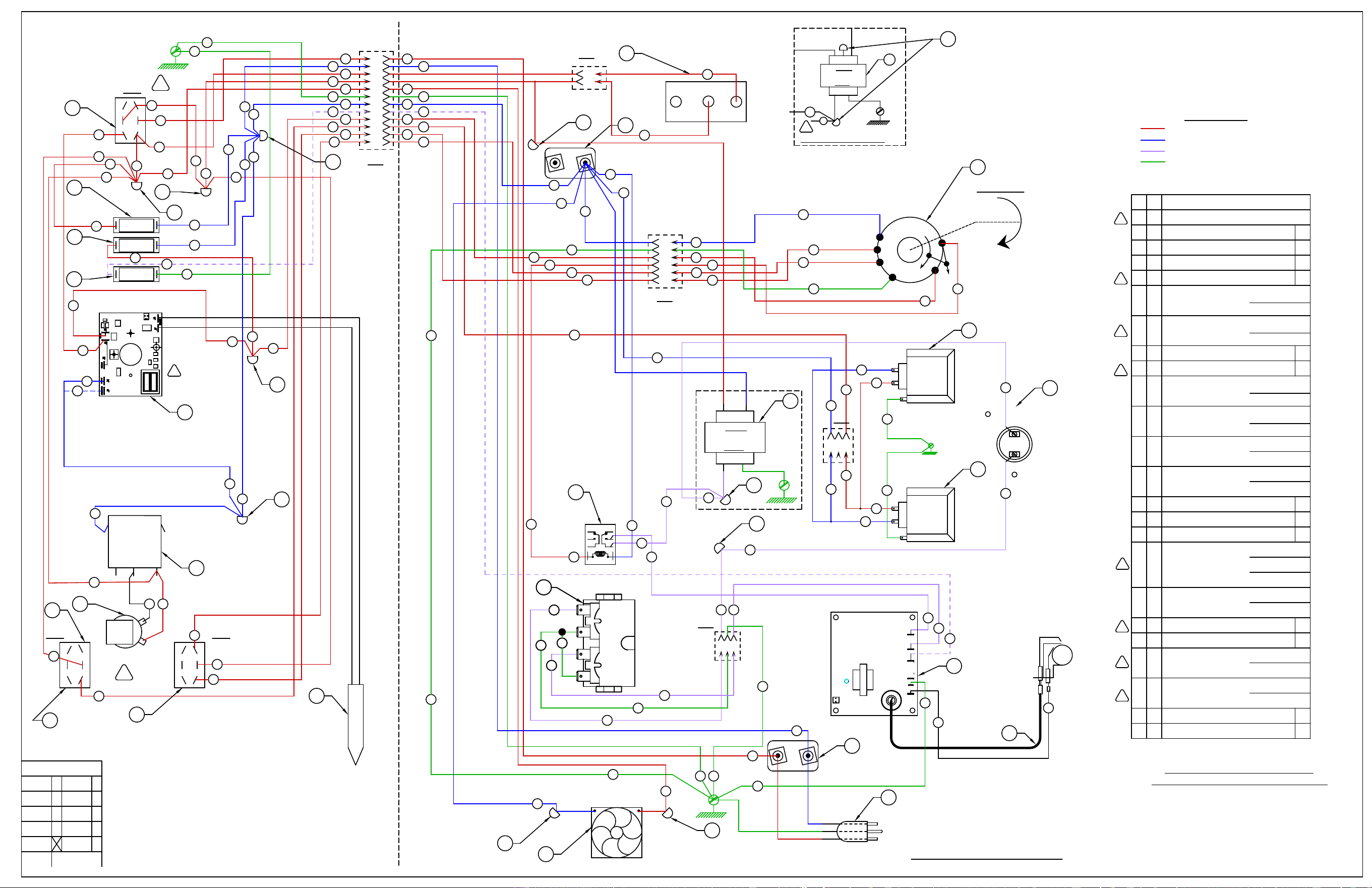
WHITE
BLACK
GREEN
GND.
DOOR SWITCH
GND.
YELL.YELL.
WHT.
BK.
24 V.
120 V.
GND.
3
2
1
GN
GN
92
91
90
93
TOP LAMP
BOTTOM LAMP
MOTOR
2 SPEED
10
48
48
6
7
13
44
46
L
I
M
I
T
54
54
K
L
S
P
N
L
W
M
SEE SCHEMATIC DECAL 424199-1
5
9
M
240 VOLT TRANSFORMER WIRING
RD
BK.
BLU.
240 V.
24 V.
YELL. YELL.
54
GND.
120 VOLT UNITS PROVIDED
WITH 3 PRONG GROUNDED
PLUG.
BLOWER
ROTATION
FRONT VIEW
CONNECT 200-240 VOLT
SUPPLY TO L1 & L2
L1 L2
SINGLE BURNER CONVECTION OVEN 120 & 200 V.
SOLID STATE CONTROL WIRING DIAGRAM
Y
Y
CODES
J
E
W
MAN
NC
X
V
A
PMI
VC
ACAD
REQ. IT.
DESCRIPTION
FIN.
WIRING INFORMATION
FOR UNITS LISTED
OVEN
BURNER
COM
HI
LO
97
98
RELAY
HEATING
T
X
S1
S1
5655
55
56
57
59
57
59
58
58
62
62
63
C-2
NO NO
COIL
C
COIL
C
NC NC
NC
NO
C
11
12
55
1 2 3
3
1
2
AB
AB
AB
AB
AB
AB
SPARK
OUT
MODULE
IGNITION
FENWAL
1
2
C-3
58
M
8
8
46
13
1
2
3
4
5
6
11
97
13
12
98
63
63
12
11
R
1
2
3
3
1
12
10
9
5
1
11
2
6
7
1
2
3
4
5
6
7
8
9
10
11
12
6
H
39
38
84
BUZZ
83
GND.
48
7
43
38
J
48
82
10
40
3
LIGHTS
20
11
5
SPEED
21
12
41
42
A
35
/COOL DOWN
ON/OFF
4
3
1
36
2
9
5
10
12
11
6
8
7
9
1
4
2
3
B
E
P
O
R
20
21
S1
S2 S3
Z
36
8
C-1
81
G
28
C
F
40
C
B
42
HEATING
NO IGNITION
43
8
POWER ON
41
T
D
39
TEMP. CONTROL
35
CONNECT FOR 208-240V.
39
CONNECT FOR 120V.
1 R RELAY, HEATING
120 VOLT
200 -240 V.
TIMER - 1 HOURH1
120 VOLT
200-240V. 50HZ
200-240V. 60HZ
1 G BUZZER
120 VOLT
200 -240 V.
1 P TRANSFORMER 24V. OUT
120 VOLT
200 -240 V.
2 N LAMP ASSEMBLY, BJB
120 VOLT
200 -240 V.
-LIMIT CONTROL 550FS1
-BLOCK,PORCELAIN ASSEMBLYL2
-SWITCH, LIMIT (DOOR)K1
-SWITCH, TOGGLE D.P.D.T - FANJ1
-SWITCH, TOGGLE D.P.D.T CENT.OFFA1
1 M MOTOR 2 SPEED FIR
120 VOLT
200 -240 V.
-CONTROL, SPARK IGNITIONT1
-CORD SET 120V. UNITS ONLYW1
1 U MAXITROL 200 VALVE
NAT. GAS
L.P. GAS
1 V FAN, COOLING
120 VOLT
200 -240 V.
-WIRE, SPARK IGNIT. 36"X1
-PROBE, THERMISTORZ1
K
L
-LIGHT,INDICATOR "NO IGNITION" 28V.C1
1 B LIGHT "ON"
120 VOLT
200 -240 V.
1 B1 LIGHT "HEAT"
120 VOLT
200 -240 V.
P
P
-TEMP. CONTROL - NCCD1
S
-SWITCH, TOGGLE D.P.D.T. - LIGHTS AA1
S
T
AA
J
1
2
3
10
44
44
92
93
GN
V
GN
GN
GN
GN
N
2
B1
AC
AC
AB
AB
AB
C-4
C-5
BLACK
WHITE
GRAY
GREEN
BLUE
RED
1
2
2
3
U
1
2
2
3
U
1
2
2
3
U
TIMER
a
b
b0
N
a1
82
W1
DERIVED FROM 00-424198
REV. W1
AI5635
28
FC1-
FC1+
S1
GND
GV1
TH
GV2
NC
INDICATOR
DIAGNOSTIC
RED
LED
L1 LINE VOLTAGE
L2 LINE VOLTAGE
24VAC VOLTAGE
GND
LENGEND
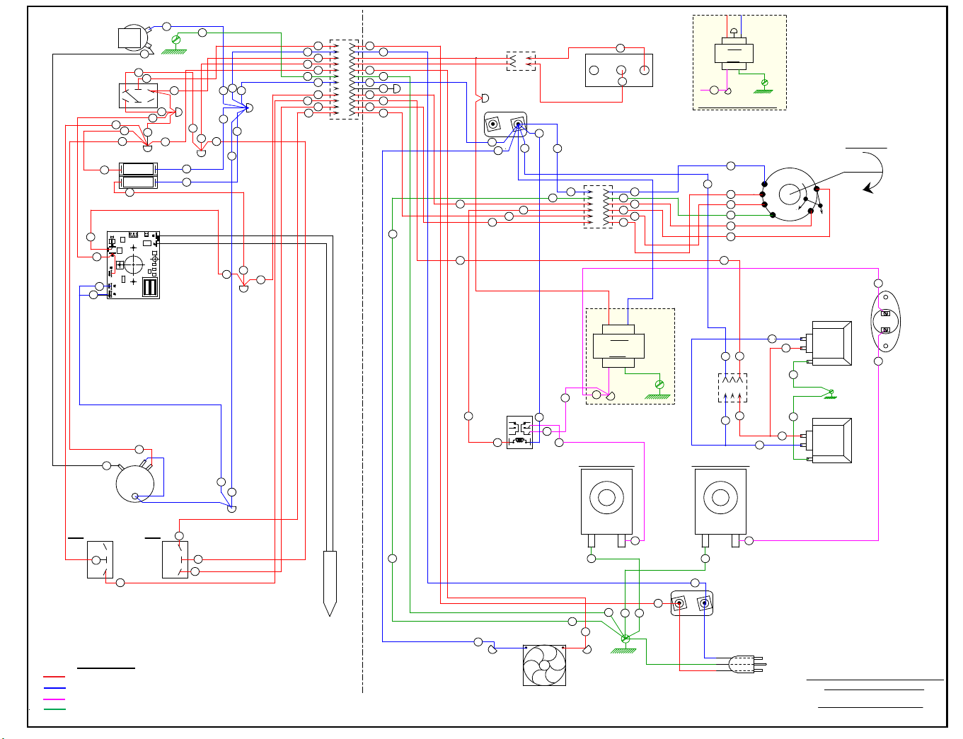
VC4GD & VC6GD 120 & 200 VOLT
WIRING DIAGRAM VC WITH STANDING PILOT
YELL.YELL.
WHT.
BK.
24 V.
120 V.
20
S2
38
TIMER
11
10
21
SPEED
S3
LIGHTS
12
66
4 1
3
64
WITH 3 PRONG GROUNDED
120 VOLT UNITS PROVIDED
DERIVED FROM 499814-Y4
SUPPLY TO L1 & L2
5
46
GND.
6
48
CONNECT 200-240 VOLT
WHITE
BLACK
GREEN
PLUG.
1
L1 L2
2
48
54
92
55
GND.
GN
LAMP TOP
OVEN
GND.
55
20
38
3
64
5
9
765
GND.
66
BUZZ
65
6
13
98
93
44
90
91
LAMP BOTTOM
OVEN
7
46
44
COM
11
12
97
LO
HI
13
2 SPEED
MOTOR
L
I
T
M
I
54
ROTATION
BLOWER
FRONT VIEW
RD
BK.
BLU.
240 V.
24 V.
YELL. YELL.
240 VOLT TRANSFORMER WIRING
GND.
54
WIRE BLUE AS BLACK
WIRE BLACK AS WHITE
SOLENOID, LIMIT
U
43
HEATING
43
42
40
POWER ON
40
41
41
42
2
9
B
E
P
O
R
28
39
RELAY
HEATING
63
59
58
62
62
63
NO NO
COIL
C
COIL
C
NC NC
59
SOLENOID MAIN
U
48
48
12
10
9
5
1
11
2
6
7
1
2
3
4
5
6
7
8
9
10
11
12
/SABBATH
ON/OFF
3
1
36
5
10
12
11
6
7
9
1
4
2
3
8
DOOR SWITCH
3
8
NC
NO
C
1
2
4
21
36
35
3
39
28
35
CONNECT FOR 208-240V.
39
6
5
4
3
2
1
GN
GN
GN
13
GN
63
12
11
GN
10
10
BLACK
WHITE
GRAY
GREEN
BLUE
RED
GN
11
12
98
GN
97
13
1
2
3
GN
92
93
10
44
58
AI4955
L1 LINE VOLTAGE
L2 LINE VOLTAGE
24VAC VOLTAGE
GND
LENGEND
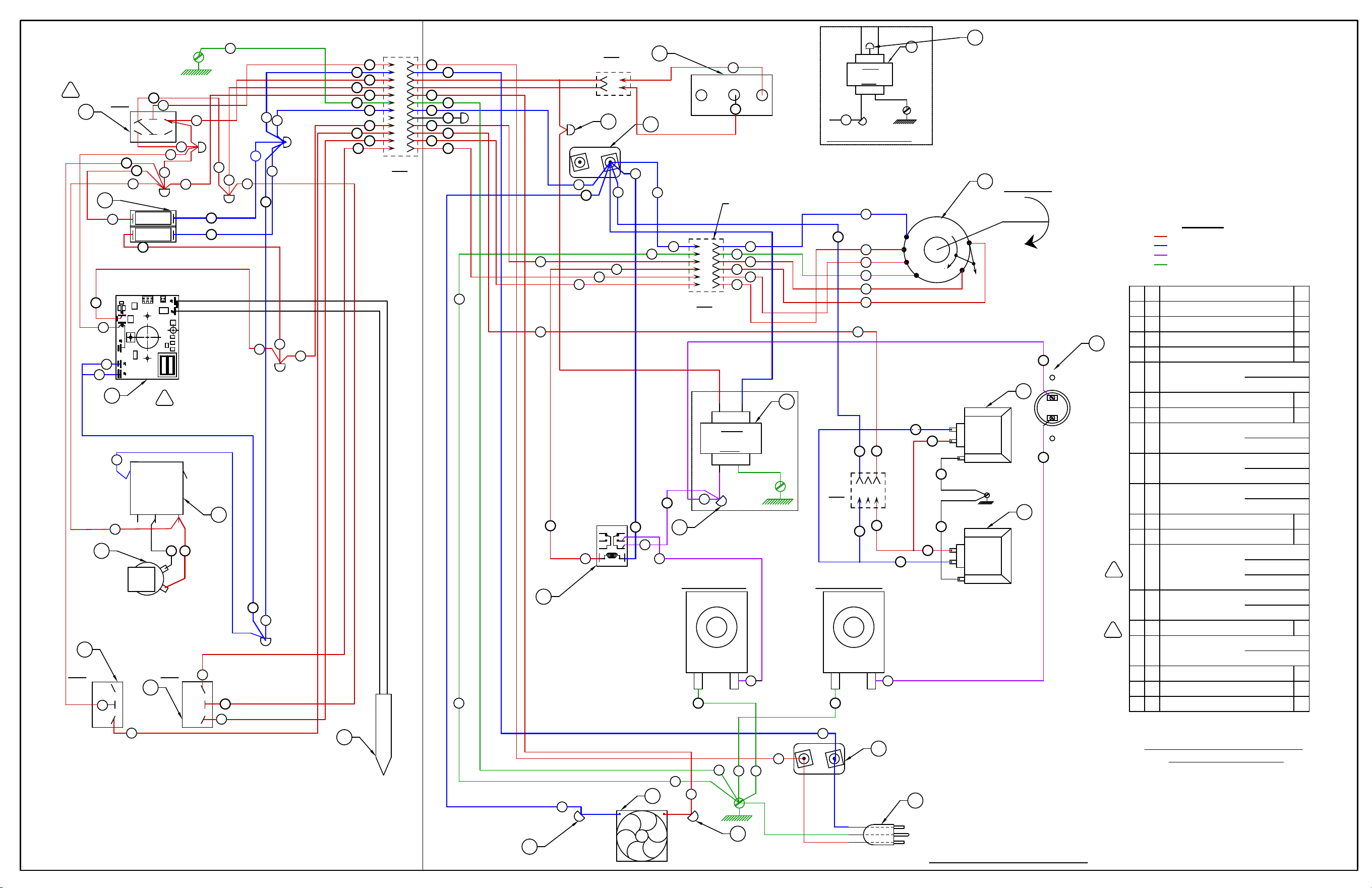
VC4GD & VC6GD 120 & 200 VOLT
WIRING DIAGRAM VC WITH STANDING PILOT
REQ. I T.
DESCRIPTION
FIN.
WIRING INFORMATION
FOR UNITS LISTED
1 P TRANSFORMER 24V. OUT
120 VOLT
200 -240 V.
YELL.YELL.
WHT.
BK.
24 V.
120 V.
AB
20
A1
S2
38
A1
11
10
21
SPEED
S3
LIGHTS
12
WITH 3 PRONG GROUNDED
120 VOLT UNITS PROVIDED
SEE SCHEMATIC DECAL 499814-Y4
SUPPLY TO L1 & L2
5
46
AB
GND.
V
6
48
CONNECT 200-240 VOLT
WHITE
BLACK
GREEN
PLUG.
W
1
L1 L2
2
L
-SWITCH, ROCKER D.P.D.T CENT.OFFA1
48
AA
54
92
55
GND.
GN
LAMP TOP
OVEN
GND.
PHOENIX TIMER - 1 HRH1
120 VOLT
240V. 50HZ
240V. 60HZ
1 G BUZZER
120 VOLT
200 -240 V.
1 M MOTOR 2 SPEED - FIR
120 VOLT
200 -240 V.
-BLOCK,PORCELAIN ASSEMBLYL2
2 N LAMP ASSEMBLY
120 VOLT
200 -240 V.
55
20
38
3
5
9
7
GND.
6
13
98
M
93
44
P
90
91
LAMP BOTTOM
OVEN
N
7
46
44
COM
11
12
97
LO
HI
13
2 SPEED
MOTOR
1 V FAN, COOLING
120 VOLT
200 -240 V.
-LIMIT CONTROL 550FS1
L
I
T
M
I
S
54
-WIRE NUT BLUEAB4
-WIRE NUT YELLOWAA1
-CORD SET 120V. UNITS ONLYW1
ROTATION
BLOWER
FRONT VIEW
L
RD
BK.
BLU.
240 V.
24 V.
YELL. YELL.
240 VOLT TRANSFORMER WIRING
GND.
M
AB
54
WIRE BLUE AS BLACK
WIRE BLACK AS WHITE
-HARNESS, SWITCH PANELAC1
SOLENOID, LIMIT
U
-SOLENOID GAS VALVE 24V.U2
43
HEATING
43
42
40
POWER ON
40
41
41
42
2
9
B
E
P
O
R
B
Z
D
28
39
RELAY
HEATING
R
63
59
58
58
62
62
63
NO NO
COIL
C
COIL
C
NC NC
59
SOLENOID MAIN
U
48
48
1 B LIGHT 'HEAT''POWER ON'
120 VOLT
200 -240 V.
-PROBE, THERMISTORZ1
12
10
9
5
1
11
2
6
7
1
2
3
4
5
6
7
8
9
10
11
12
A
/SABBATH
ON/OFF
3
1
36
5
10
12
11
6
7
9
1
4
2
3
S1
8
C-1
C
DOOR SWITCH
3
8
K
NC
NO
C
AB
1
2
C-3
4
21
36
-SWITCH, LIMIT (DOOR)K1
35
-SWITCH, ROCKER S.P.D.T A12
3
39
28
35
CONNECT FOR 208-240V.
39
-TEMPERATURE CONTROL S.S. D1
F
F
6
5
4
3
2
1
C-5
GN
GN
GN
13
GN
63
12
11
GN
10
10
BLACK
WHITE
GRAY
GREEN
BLUE
RED
GN
11
12
98
GN
97
13
1
2
3
C-4
GN
92
93
10
44
N
ITEM "M"
H
84
BUZZ
83
81
G
TIMER
a
b
b0
N
a1
82
82
H
DERIVED FROM: 00-499814-Y REV. H
AI5743
LEGEND
L1 LINE VOLTAGE
L2 LINE VOLTAGE
24VAC
GND
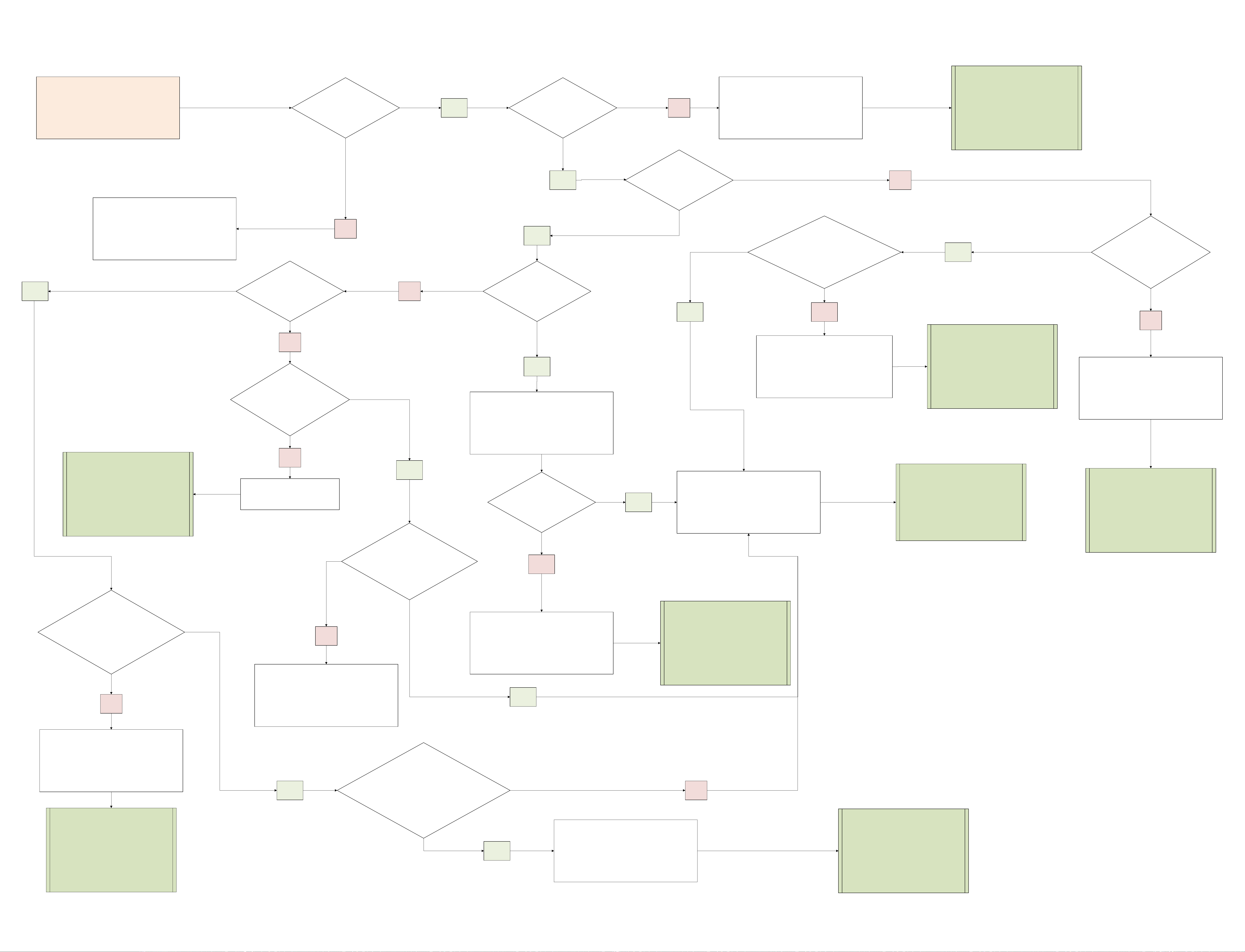
TURNPOWERON ISPOWERLIGHTON?
NOCHECKINCOMINGPOWER
YES ISHEATLIGHTON?
YES
NO
REFERENCE"TEMPERATUREPROBE
TEST"INSERVICEMANUAL.
DOES"NOIGNITION
LIGHT"STAYON?
YES
NO
ISTHEHEATRELAY
ENERGIZED?
NO
DOYOUHAVEAFLAME?
YES
ISTHERE24VATTHEIGNITION
BOARDTERMINAL?
YES NO
REFERENCE"CONTROLPANEL
COMPONENTS"INSERVICE
MANUAL
NODOYOUHAVEASPARK?YES
NO
CHECKTEMPCONTROLPROBE
ISSPARKGAPSET
CORRECTLY?
REFERENCE"VERIFICATIONOF
SPARKATIGNITOR"INSERVICE
MANUAL
YES
NO
YES
ADJUSTSPARKGAP
ISTHEHIGHVOLTAGEWIRE
OKAY?
CHECKFLAMESENSOR&LOWVOLTAGE
WIRE
AREBOTHGOOD? YES
NO
REPLACEFLAMESENSOR
CHECKMOTORCENTRIFUGALSWITCH
REPLACEIGNITIONBOARD
REFERENCE"MOTORCENTRIFUGAL
SWITCHTEST"
REFERENCE"IGNITIONCONTROL
MODULE"INSERVICEMANUAL
REFERENCE"SPARKIGNITORAND
FLAMESENSE"INSERVICEMANUAL
YES
NO
REPLACEHIGHVOLTAGEWIRE
DOYOUHAVE24VATTHEGAS
VALVE?
DOYOUHAVE24VOTSATTHEGASVALVE
UPONSPARK?
NO
YES
REPLACEHIGHLIMITSWITCH
REFERENCE"HIGHLIMIT
THERMOSTAT"INSERVICE
MANUAL
NO
YES
REPLACEHEATRELAY
REPLACEGASVALVE
REFERENCE"GASSOLENOIDVALVE"
INSERVICEMANUAL
MECHANICAL CONTROLS TROUBLESHOOTING