
PROFESSIONAL SERIES
HIGH OUTPUT IN-CEILING LOUDSPEAKER
PS-C85RTBF AND PS-C85BB | BAFFLE AND BACK BOX
MANUAL
2
IMPORTANT SAFETY INSTRUCTIONS
This product is intended to be installed by professional
AV integrators and installers only. This product manual
is intended to serve as a general guideline for most
applications. It is the installer’s responsibility to ensure
this product is installed in accordance with local
building codes and regulations. Consult a local authority
for specific requirements, regulations, and building
codes of the jurisdiction in which this product is to be
installed.
READ THIS DOCUMENT IN ITS
ENTIRETY BEFORE ATTEMPTING USE
1. Read these instructions.
2. Keep these instructions.
3. Heed all warnings.
4. Follow all instructions.
5. Clean only with a dry cloth.
6. Do not block any ventilation openings. Install in
accordance with the manufacturer’s instructions.
7. Do not install near a heat source such as radiators,
heat registers, stoves, fireplaces, or other apparatus
(including amplifiers) that produce heat.
8. Only use attachments/accessories specified by
Sonance.
9. Refer all servicing to qualified service personnel.
TABLE OF CONTENTS
2 Box and Contents
3 Product Features
4 Amplifier Selection
4 Wire Selection
70V/100V System
8 ohm System
4 Loudspeaker Placement
4 Grille Painting
5 Assembly and Installation
9 Technical Specifications
10 Certifications and Safety Agency
10 Technical Assistance and Service
11 Warranty
PROFESSIONAL SERIES HIGH
OUTPUT IN-CEILING LOUDSPEAKER
PS-C85RTBF and PS-C85BB
BOX CONTENTS
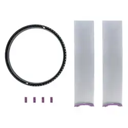
IN-CEILING LOUDSPEAKER BAFFLE
(1) PS-C85RTBF
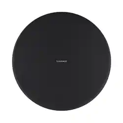
(1) Round White Loudspeaker Grille
(Black Grille Optional)
(1) Variable Dispersion Horn
(1) Collar Removal Tool
PS-C85RTBF
BAFFLE
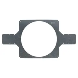
PS-C85BB
BACK BOX
PRODUCT DESCRIPTION
From Sonance, the company that created the
architectural audio category, comes a range of
professional loudspeakers that set a new benchmark
in sound quality and aesthetics for commercial
environments. Sonance Professional Series High
Output is a range of 70V/100V or low impedance and
tap selectable loudspeakers available as in-ceiling,
surface mount, or pendant models. These High Output
models achieve elevated SPL levels with the ability to
field-configure each loudspeaker for wide or narrow
directivity. Their shared voicing across form factors
ensure seamless sonic integration when deployed
together throughout professional and commercial
spaces. The In-Ceiling Loudspeakers feature a one-
piece, bezel-less grille that is magnetically secured
and allows for a one-step painting process to simplify
installation and minimize visual distraction. The optional
square grille adapter allows the loudspeakers to match
the aesthetic of square down lights and HVAC grilles.
Sealed metal enclosures, integrated cable and conduit
clamping, seismic attachment and connector cover
allow them to be installed in commercial environments
where UL 1480A and UL 2043 are required by code.
Scan QR code for additional
information and resources. For
technical support call 949.492.7777
or visit www.sonance.com/
professionalseries
IN-CEILING LOUDSPEAKER BACK BOX
(1) PS-C85BB
(1) Cutout Template
(1) Euroblock Wire Connector
(1) Cable & Conduit Clamp
3
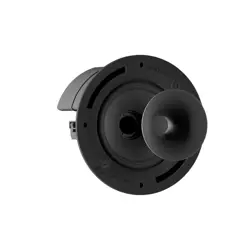
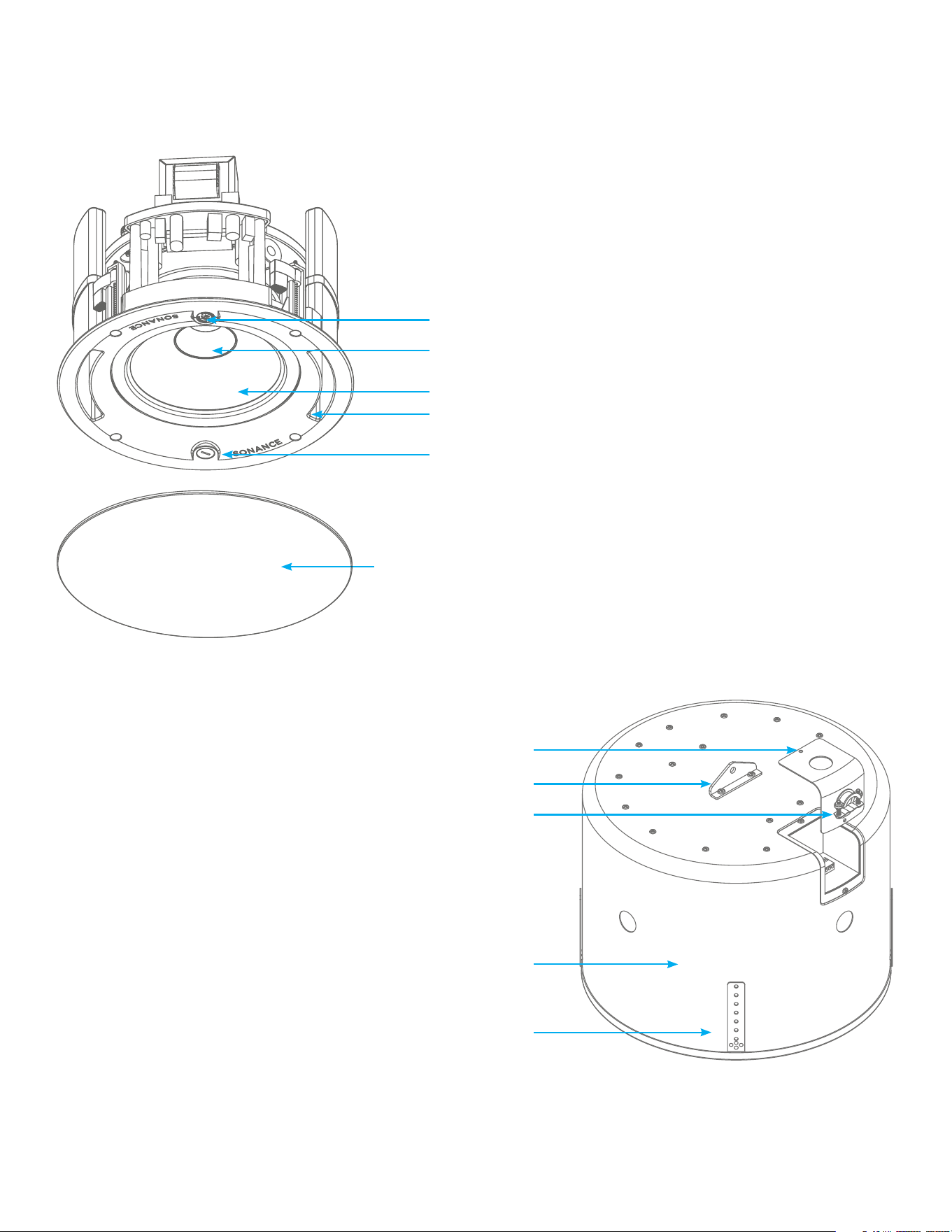
PRODUCT FEATURES
One Piece Paintable Grille with
Magnetic Retention
Cable and Conduit Clamp
Seismic Support Tab
Connector Cover with Dual Knockouts
Variable Dispersion Horn/Collar Assembly
Transformer Tap and Bypass Selector
Metal Back Can
High Eciency Ported Design
High Excursion Woofer
Variable Dispersion Selector Switch
Seismic Support
4
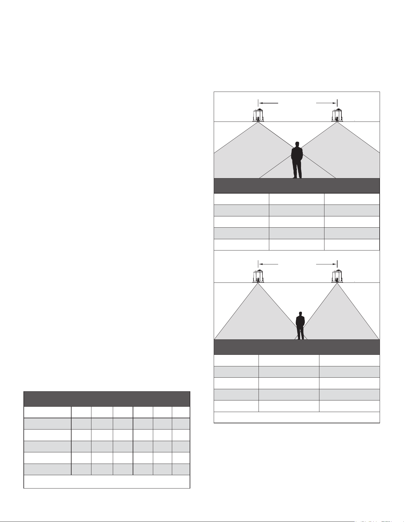
LOUDSPEAKER PLACEMENT
Sonance Professional Series Loudspeakers possess
extremely smooth and predictable o-axis frequency
response. The chart below (see Figure 2) shows how far
apart the loudspeakers can be placed in a distributed
audio system. The calculations are based on +/-45
degrees of coverage from the loudspeaker, and listener
ear heights of 62” for standing and 40” for seated.
WIRE SELECTION
WIRE GAUGE – 70V/100V SYSTEM
The most common wire used on commercial 70 volt
systems is 18 AWG, 2 conductor, stranded, and jacketed
without a shield. The wire starts at the amplifier location
and is paralleled at each loudspeaker location. Wire
length using 18 AWG is appropriate up to 700ft with a
100 watt load. If you double the load (sum of your tap
settings), you will reduce the footage by half, to 350ft.
Conversely, if you halve the load, you may double the
acceptable wire length, i.e., a 50 watt load is safe over
1,400ft of 18 AWG. Stepping up to 16 AWG wire extends
the allowable run length by approximately 35%. For
example, a 100 watt load can go 700ft on 18 AWG; the
same load may be placed on 1,100ft of 16 AWG.
WIRE GAUGE – 8 OHM SYSTEM
When using Sonance Professional Series loudspeakers
in an 8 ohm system the total wire resistance should
be less than 10% of the loudspeaker impedance. The
loudspeakers are nominally 8 ohms impedance, so your
total wire resistance should be no more than 0.8 ohms.
In simple terms, the extra resistance from the wire will
have a very negative aect on the sound quality of the
loudspeaker. The sound can be less dynamic, definition
of bass frequencies can be reduced, and in extreme
cases, the high frequencies can be attenuated. Amplifier
power is also wasted in the wire, reducing the maximum
output level of the system. Please refer to the following
chart (see Figure 1) when deciding on the appropriate
wire gauge for your installation.
AMPLIFIER SELECTION
When choosing an amplifier, the maximum number of
loudspeakers and the output level of each loudspeaker
must be known. The sum of the tap settings should
never exceed 80% of the amplifier’s rated output. For
example, if there are five loudspeakers and the taps
are set at 15 watts, the load would be 75 watts (5 x 15
watts = 75 watts). To arrive at the needed power for this
number of loudspeakers, simply divide the total load
by 0.8. In this case, 75/0.8 = 93.75 watts. Therefore, a
standard 100 watt amp would safely drive this load. To
calculate the amount of usable power an amp oers,
simply multiply the rated output by 0.8, i.e., 100 watts x
0.8= 80 watts.
Figure 1: Wire Resistance
GRILLE PAINTING
Sonance PS In-Ceiling Loudspeaker grilles completely
cover the exposed loudspeaker frame, so only the grilles
(not the loudspeakers themselves) require painting.
IMPORTANT: Mask the front flange and bae of the
loudspeaker before painting the wall or ceiling (see
Figure 3).
Figure 2
WIRE RESISTANCE IN OHMS VS. LENGTH OF CABLE RUN
Distance in Feet 50’ 100’ 150’ 200’ 250’ 300’
20 AWG 0.86 1.73 2.59 3.45 4.32 5.18
18 AWG 0.65 1.3 1.94 2.59 3.24 3.89
16 AWG 0.43 0.85 1.28 1.71 2.14 2.56
14 AWG 0.27 0.53 0.81 1.08 1.35 1.62
12 AWG 0.17 0.34 0.51 0.68 0.85 1.02
SPEAKER
SPACING
COVERAGE
AREA
COVERAGE
AREA
Speaker Spacing in Feet for a Distributed Audio System
8-Foot Ceiling
5.7’ (1.7m) Apart
9.7’ (3.0m) Apart
13.7’ (4.2m) Apart
17.7’ (5.4m) Apart
9.5’ (2.9m) Apart
13.5’ (4.1m) Apart
17.5’ (5.3m) Apart
21.5’ (6.6m) Apart
Standing Listener Seated Listener
10-Foot Ceiling
12-Foot Ceiling
14-Foot Ceiling
LOUDSPEAKER SPACING WHEN NARROW HORN IS
INSTALLED/SELECTED FOR DISTRIBUTED AUDIO SYSTEM
Standing Listener Seated Listener
16ft Ceiling 17.9ft (5.5m) Apart 21.2ft (6.5m) Apart
20ft Ceiling 24.6ft (7.5m) Apart 28ft (8.5m) Apart
24ft Ceiling 31.3ft (9.5m) Apart 34.7ft (10.6m) Apart
28ft Ceiling 38ft (11.6m) Apart 41.4ft (12.6m) Apart
SPEAKER
SPACING
COVERAGE
AREA
COVERAGE
AREA
Speaker Spacing in Feet for a Distributed Audio System
8-Foot Ceiling
5.7’ (1.7m) Apart
9.7’ (3.0m) Apart
13.7’ (4.2m) Apart
17.7’ (5.4m) Apart
9.5’ (2.9m) Apart
13.5’ (4.1m) Apart
17.5’ (5.3m) Apart
21.5’ (6.6m) Apart
Standing Listener Seated Listener
10-Foot Ceiling
12-Foot Ceiling
14-Foot Ceiling
LOUDSPEAKER SPACING WHEN WIDE COLLAR IS
INSTALLED/SELECTED FOR DISTRIBUTED AUDIO SYSTEM
Standing Listener Seated Listener
8ft Ceiling 5.3ft (1.6m) Apart 9.3ft (2.8m) Apart
10ft Ceiling 9.3ft (2.8m) Apart 13.3ft (4m) Apart
12ft Ceiling 13.3ft (4m) Apart 17.3ft (5.3m) Apart
14ft Ceiling 17.3ft (5.3m) Apart 21.3ft (6.5m) Apart
5
PAINTING THE GRILLES
1. Prime the grille with a metal primer/bonder in
a spray can. Carefully follow the manufacturer’s
directions on the can.
2. We recommend using water-based latex paint. Thin
the paint with a proper thinning agent to a ratio of
1:1 paint-to-thinner, and strain it through a standard
mesh strainer to remove any lumps.
IMPORTANT: Due to its increased durability, oil-based
paint should be considered for Professional Series
Loudspeakers that are installed outdoors.
3. Use a small touch-up gun or cap-spray gun with a
#3 tip for painting.
• Set the nozzle with a medium to wide fan.
• Set the pressure regulator to 60psi.
• Lightly spray the front of the grille in three quick
strokes from approximately 10” away.
• Let the paint set for a minute, then turn the grille 90
degrees and lightly spray the grille again in three
quick strokes. Repeat this step until all four sides of
the grille have been evenly painted.
4. While the paint is still wet, inspect the grille and
make sure that excess paint has not collected
underneath the grille frame, and that none of the
grille perforations are filled with paint. If any are,
use compressed air to blow the paint out of the
perforations.
PREPARING THE GRILLES FOR PAINTING
Carefully remove the scrim cloth from the underside of
the grille. The scrim cloth is held in place with a light
tacking glue. Use a heating agent such as a heat gun
or hair dryer to soften the glue and carefully remove
the cloth. Since, you will need to replace it when you’re
done painting the grille, be careful not to deform the
cloth’s shape while removing it. Deformation will make it
very dicult to properly replace the cloth on the grille.
Remove any adhesive residue from the back of the grille
before beginning painting.
Figure 3
MASK ENTIRE
FLANGE
Mask the Flanges and Baes of Installed
Speakers Before Painting the Ceiling
IMPORTANT: If any grille perforations are plugged with
paint after the paint has dried, use a straight pin or
sewing needle to carefully remove the paint.
5. Once the paint has thoroughly dried, replace the
scrim cloth on the back of the grille and mount the
grille on the loudspeaker.
BEFORE YOU BEGIN
Install the appropriate dispersion assembly into the
PS-C85RTBF loudspeaker bae. Sonance Professional
Series High Output Loudspeakers feature a magnetic
interchangeable collar/horn assembly that can be
swapped out to achieve the desired coverage. For wide
coverage applications, leave the collar assembly in
place (comes installed as default). For narrow coverage
applications, remove the collar and install the horn.
The selector located on the bae must be assigned
to the appropriate position to match the installed
assembly(see Page 7 for more about dispersion
assembly selection).
Figure 4: Variable
Dispersion Horn and
Collar Assembly
CollarHorn
SAFETY PRECAUTION: Attaching the seismic tab of
the PS-C85BB back box to a support line is highly
recommended for additional safety.
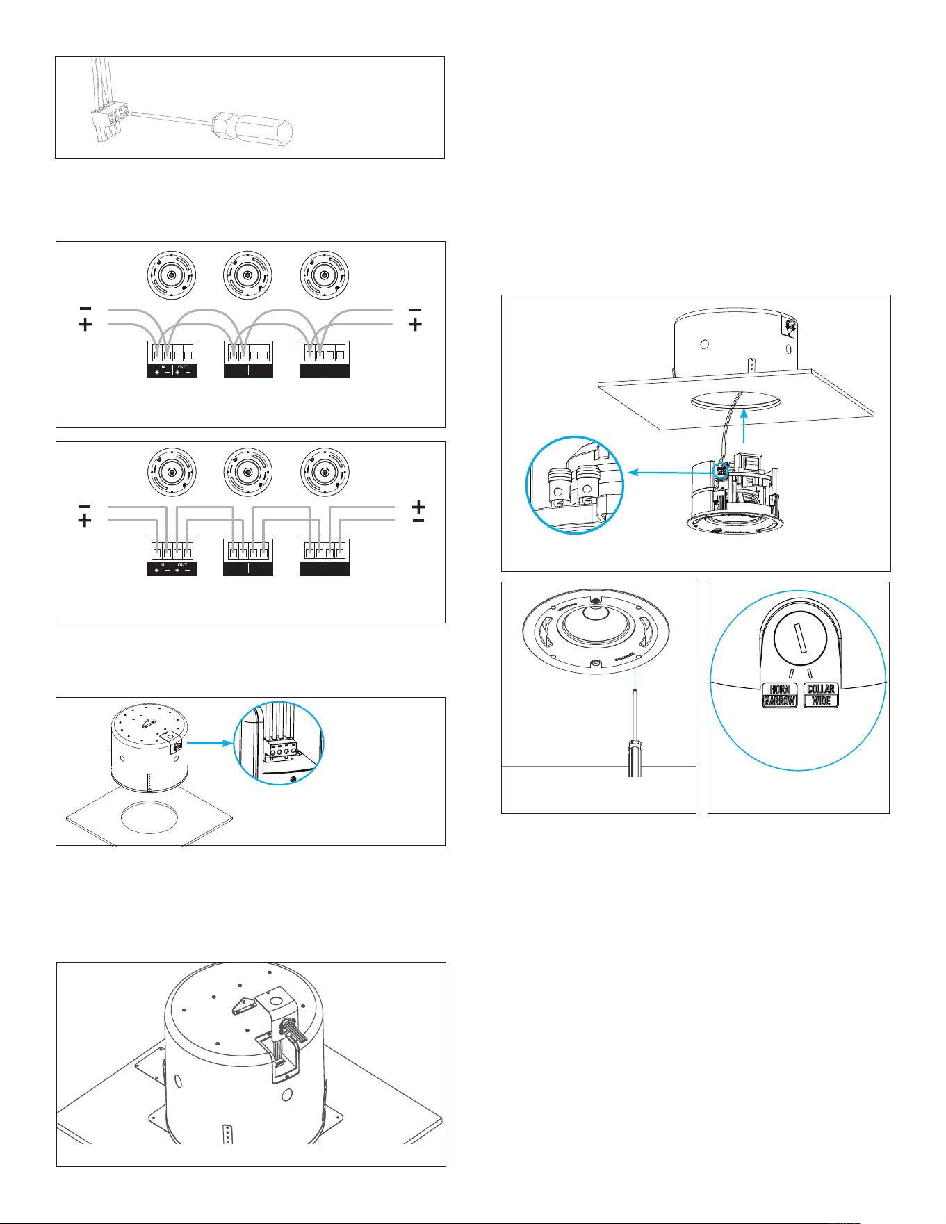
1. Run the speaker wire from the amplifier to the back
box location.
2. Connect the wires to the Euroblock wire connector
(included with PS-C85BB Loudspeaker Back
Box).Strip approximately 0.1875” (5mm) of the
insulation o each wire. Insert the wire into the
correct square opening on the connector. Use a small
flat head screwdriver to tighten the corresponding
screw to secure the wire (see Figures 5 and 6).
Pin 1 + Positive In
Pin 2 - Negative In
Pin 3 + Positive Out
Pin 4 - Negative Out
Figure 5: Euroblock Connector
+
_
IN OUT
+
_
6
II
5. Route the wires through the Strain Relief Fitting
on the back of the back box. Tighten the screws on
the strain relief to clamp the wires. Make sure not to
over-tighten the screws and damage the wire (see
Figure 10).
Figure 10: Route Wires and Tighten Screws
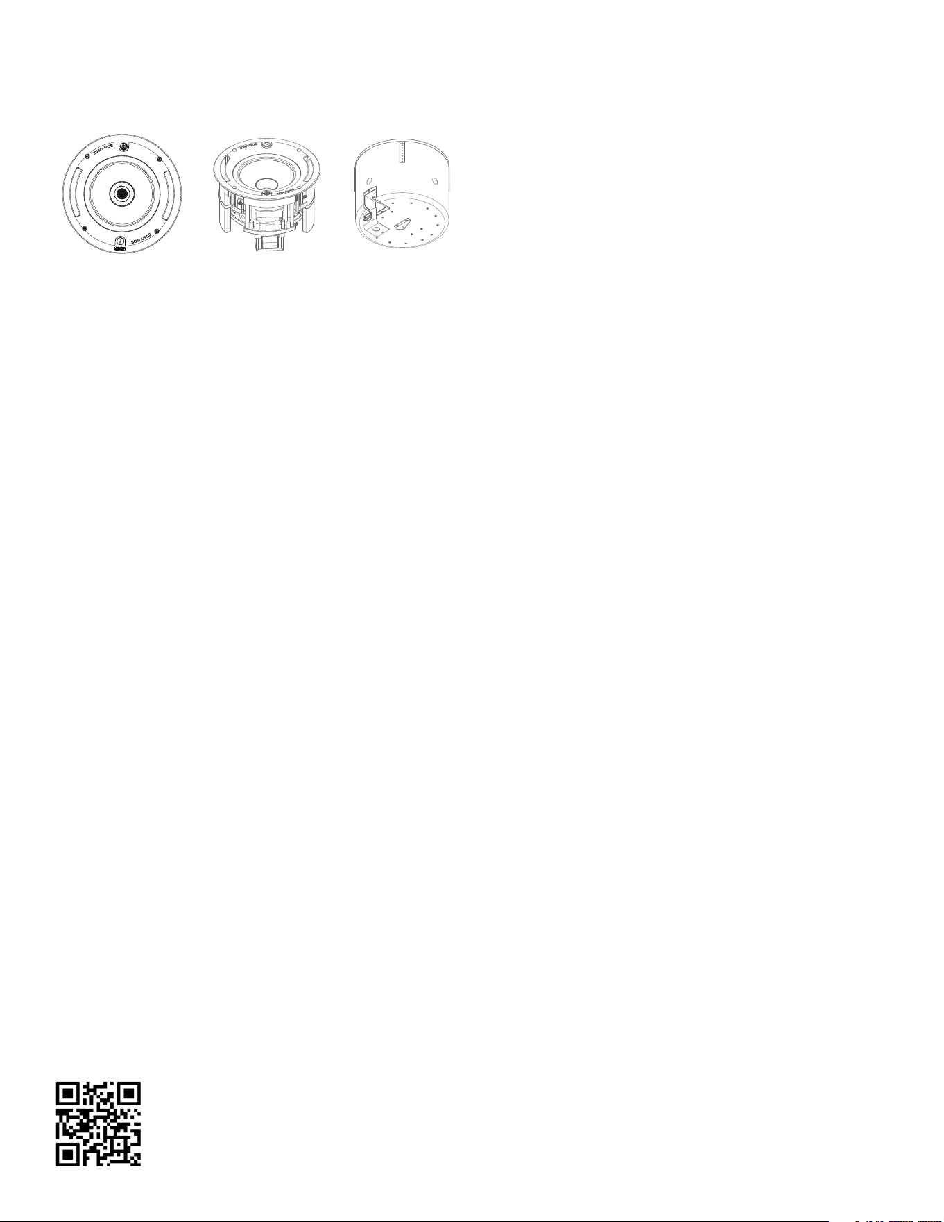
PS-C85RTBF BAFFLE INSTALLATION
NOTE: If square grilles are being used, the adapter
frame must be installed at this time.
6. Once drywall is installed, the PS-C85RTBF
loudspeaker bae assembly can be inserted into
the back box opening. First, join the wiring harness
between the back box and the speaker bae.
Connect the stripped wire to the spring loaded
wire terminals on the back of the speaker bae,
connecting the black wire to the black terminal and
the red wire to the red terminal (see Figure 11).
Figure 11: Insert Bae Into Back Box Opening
4. Once all the wires are terminated. Plug the
Euroblock Connector into the back of the PS-C85BB
loudspeaker back box (see Figure 9).
Figure 9: Plug
in Euroblock
Connector
3. When using multiple loudspeakers you can connect
the loudspeakers either in parallel or in the loop
through method as shown below (see Fig 7 and 8).
+
_
IN OUT
+
_
+
_
IN OUT
+
_
+
_
IN OUT
+
_
+
_
IN OUT
+
_
Parallel Connection To Next SpeakerFrom Power Amplifier
Loop Thru Connection To Next SpeakerFrom Power Amplifier
From Power Amplifier
To Next Loudspeaker
+
_
IN OUT
+
_
+
_
IN OUT
+
_
+
_
IN OUT
+
_
+
_
IN OUT
+
_
Parallel Connection To Next SpeakerFrom Power Amplifier
Loop Thru Connection To Next SpeakerFrom Power Amplifier
From Power Amplifier To Next Loudspeaker
Figure 7: Parallel Connection
Figure 6:
Secure the
Wire
Figure 8: Loop Through Connection
Figure 12:
Tighten Screws on Bae
Figure 13:
Dispersion Selection
7. Make sure the Roto-Lock Clamps are in the full
clockwise position so that all the clamps are tucked
into the bae to fit into the back box opening.
Insert the loudspeaker bae into the opening. Use a
screw driver or drill on lowest setting to secure the
bae to the back box via the four dog ear screws
around the bae (see Figure 12).
8. Install the appropriate dispersion assembly. Sonance
Professional Series High Output loudspeakers
feature a magnetic interchangeable collar/horn
assembly that can be swapped out to achieve the
desired dispersion. For wide dispersion applications,
leave the collar assembly in place (comes installed
as default). For narrow dispersion applications,
remove the collar and install the horn. The selector
located on the bae must be assigned to the
appropriate position to match the installed
assembly (see Figure 13).
7
• Pull up to remove the collar. The collar can be
discarded unless the installer plans to relocate the
loudspeaker in the future, in which case the collar
can be reserved.
• The horn attaches magnetically. Align the horn into
position and it will snap into place.
• Switch the selector on the front bae to the
“NARROW/HORN” position.
NOTE: If removal of the horn is required, no tool is
needed. The horn attaches magnetically and can be
installed and removed by hand.
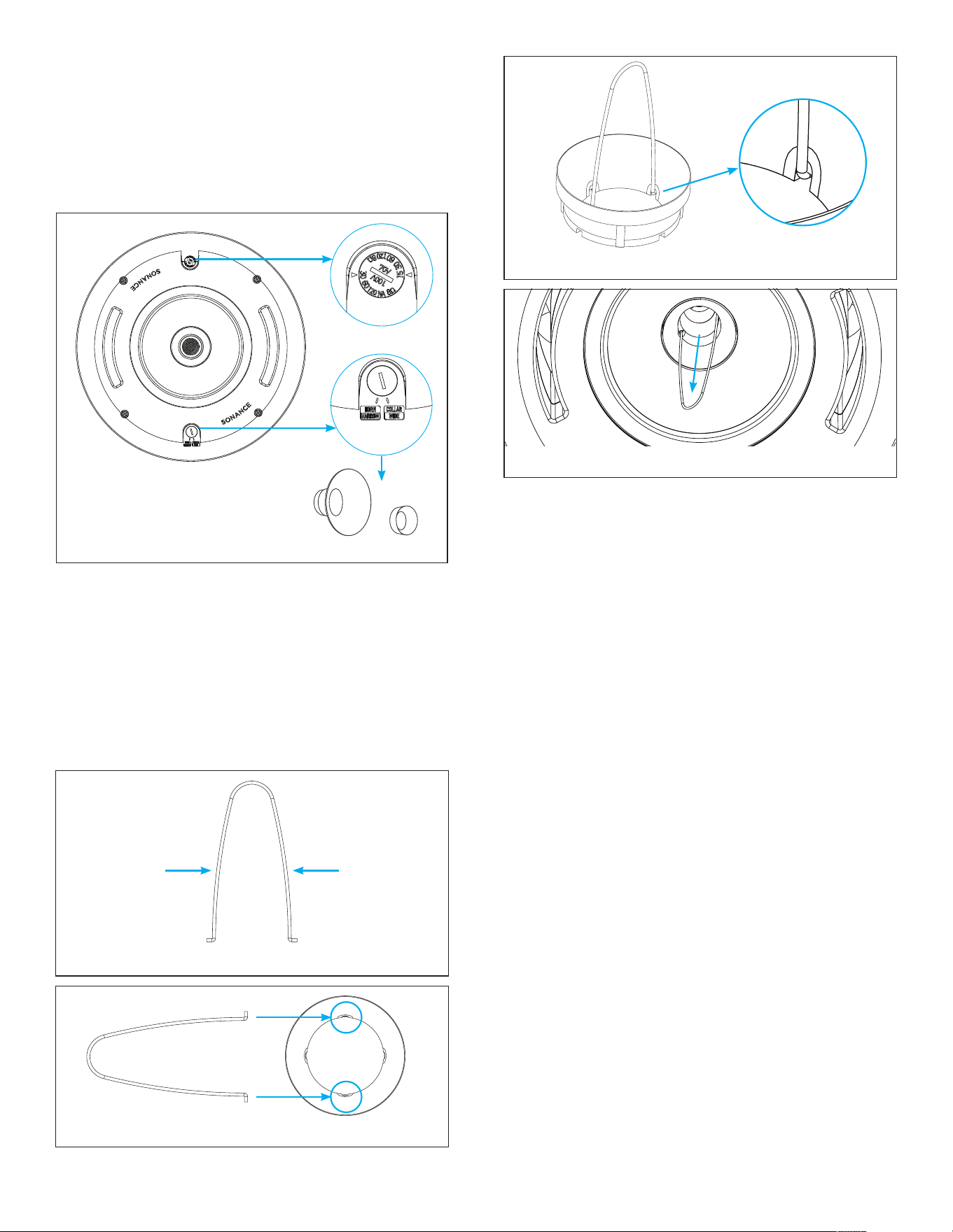
SETTING THE TRANSFORMER TAP
9. Adjust the transformer tap to the appropriate
setting. Sonance Professional Series High Output
loudspeakers are factory set for maximum output
when used with a Sonance DSP 2-750 MKIII or
another 70V/100V amplifier. No additional work is
necessary if the loudspeakers are operating in 70V
or 100V and can run at their full volume capacity.
Applications for changing the tap switch from factory
default:
• Loudspeakers are to be installed in sensitive areas
and need to be “tapped down” for lower volume.
• More loudspeakers are needed to be added to
a 70V/100V amplifier already operating at full
capacity.
• A small zone is to be driven by an 8 ohm amplifier.
8 OHM SETTINGS
Aligning the values on the dial with the arrow indicators
on either side to the 8 ohm setting bypasses the internal
transformer for operation with low impedance amplifiers.
NARROW/HORN
For applications requiring narrow loudspeaker
dispersion, the collar will need to be removed for the
horn to be installed. Sonance includes a collar claw
removal tool for easy collar removal.
• Identify the four slots on the collar marked by blue
rings.
• Align the collar removal tool with two of the slots
and snap the claw into place.
Step 1: Squeeze Tool
Step 3: Tool Snaps into Place
Step 4: Remove Collar with Tool
Squeeze
Tool
Squeeze
Tool
Step 2: Insert Tool into Collar
Figure 14: Horn and
Collar Assembly and
Selector Switch
CollarHorn
WIDE/COLLAR
This Professional Series High Output loudspeaker ships
with the collar installed.
• For applications requiring wide loudspeaker
dispersion, no assembly changes are needed.
• Ensure the selector on the front bae is in the
“WIDE/COLLAR” position.
8
Figure 15:
Grille Installation
70V TAP SETTINGS
Align the arrow positioned with the 70V values to the
desired wattage setting. Turning the dial one click
stop in either direction increases or decreases the
loudspeaker’s input power.
100V TAP SETTINGS
Align the arrow positioned with the 100V values to
the desired wattage setting. Turning the dial one click
stop in either direction increases or decreases the
loudspeaker’s input power.
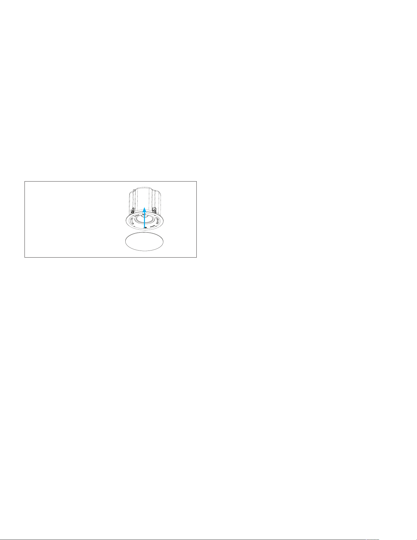
10. After the loudspeaker is installed, and transformer
tap adjustments are made, the grille can be
installed. The grille is held in place by several small,
powerful magnets on the loudspeaker frame. Place
the grille against the loudspeaker and the magnets
will hold it firmly in place. When properly installed,
the grille should make contact with the ceiling all
the way around the loudspeaker.

9
PS-C85RTBF AND PS-C85BB TECHNICAL SPECIFICATIONS
• (1) Round White Loudspeaker Grille
(Black Grille Optional)
• (1) Cutout Template
• (1) Euroblock Wire Connector
• (1) Variable Dispersion Horn
• (1) Collar Removal Tool
SKU
Transducers LF Driver
Transducers HF Driver
Frequency Range (-10dB) *
Frequency Range (-3dB) *
Long Term Power Handling (IEC) ‡
Program Power
Sensitivity (2.83V/1M) §
Long Term - Maximum SPL ‡
Program Power - Maximum SPL ‡
Rated Impedance
Transformer Taps (8 ohm Bypass)
Collar Coverage Pattern 1kHz to 10kHz †
Horn Coverage Pattern 1kHz to 10kHz †
Collar Directivity Factor (Q)
Horn Directivity Factor (Q)
Collar Directivity Index (DI)
Horn Directivity Index (DI)
Back Box Enclosure Material
Bae Material
Grille Material
Capture Thickness
Suspension Points
Enclosure Cubic Volume
Enclosure/Port Tuning
Input Connector
Operating Temperature Range
Agency Listings
Conformity
Round Trimless Grille (Dia)
Square Trimless Grille (WxH)
System Assembly Dimensions (Dia x D)
Mounting Depth (System, D)
Cutout Dimensions (System, Dia)
Product Weight (System, no Grille)
Product Weight (System, with Grille)
Shipping Weight
40231 PS-C85RTBF; 40232 PS-C85BB - Each
8” (203mm) Aluminum Cone, Santoprene Surround, Ferrite Magnet, 60.55mm
Voice Coil
1.4” (36mm) Aluminum Dome Compression Driver, Neodymium Magnet, 36mm
Voice Coil, 1500Hz Cross Frequency, 1” (25mm) Exit Size
36.6Hz – 25kHz
41.4Hz – 20kHz
150 Watts (600 Watts Peak), 100 Hours
300 Watts (1200 Watts Peak), Two Hours
91dB SPL
112dB (118dB Peak)
115dB (121dB Peak)
8 ohm Bypass
70V: 120W, 60W, 30W, 15W | 100V: 120W, 60W, 30W (8 ohm Bypass)
120 Degrees Axis Symmetric
80 Degrees Axis Symmetric
5.7 (Average 1kHz to 16kHz)
8.65 (Average 1kHz to 16kHz)
7.5dB (Average 1kHz to 16kHz)
9dB (Average 1kHz to 16kHz)
Powder Coated Steel (PS-C85BB, sold separately)
PC/ABS (UL94V-0) (PS-C85RTBF)
Steel
0” to 2.12” (0mm to 53.84mm)
Two, on Top Surface
0.83 Cubic Feet (23.5 Cubic Liters)
41.1Hz
Four pin, Euroblock with Loop Output Connections
-40 F (-39.96 C) to 140 F (60 C)
UL 1480A, UL 2043
NFPA 90A, NFPA 70
11.17” (283.8mm)
11.18” x 11.18” (284mm x 284mm)
11.07” x 7.22” (281.1mm x 184.4mm)
7.14” (181.4mm)
10.125” (257mm)
18.15 lbs. (8.23kg) EA
18.7 lbs. (8.48kg) EA
23.15 lbs. (10.15kg) PS-85RTBF; 18.65 bs. (8.46kg) PS-C85BB (sold separately)
• Replacement Horn/Collar Kit (EA) | 40251
• Replacement Round Grille White (PR) | 40239
• Round Grille Black (PR) | 40240
• Square Adaptor w/ Grille White (PR) | 40241
• Square Adaptor w/ Grille Black (PR) | 40242
• Flex Bracket (5PR) | 40270
• PS-C85BB Tile Bridge (6 Each) | 40277
• Metal Pre-construction Bracket (6 Pack)
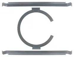
• Tile Support Rails w/ C-Ring (PR)
* In half space | † Average 1 kHz to 10 kHz | ‡ IEC 268-5 standard,
with 6 dB crest factor | § Measured in half space, ave 100 Hz – 10 kHz
| UL evaluated frequency range of 50-20kHz
INCLUDED ACCESSORIES OPTIONAL ACCESSORIES
10
CERTIFICATIONS
SAFETY AGENCY COMPLIANCE
Sonance Professional Series Loudspeaker model
PS-C85RTBF with PS-C85BB meets the following
standards:
UL-2043 fire tested for heat and visible smoke release
for discrete products and their accessories installed in
air handling spaces.
NFPA-70 National Electric Code 1996, article 300-22(c).
NFPA-90A Installation of Air Conditioning and
Ventilation Systems, section 2-3.10.1 (a), exception 3.
UL-1480A
IMPEDANCE 8 OHMS
MAX RATED POWER 150 WATTS
SUITABLE FOR USE IN AIR HANDLING SPACES
LISTED GENERAL SIGNALING EQUIPMENT SPEAKER
TECHNICAL ASSISTANCE
AND SERVICE
The Technical Assistance Department at Sonance is
available at (949) 492-7777 to answer any questions
concerning the operation and installation of your
loudspeakers between the hours of 7:00 AM and
5:00 PM Pacific time, Monday through Friday, except
holidays.
In the event your unit should need repair or service, you
may return the unit to your authorized dealer or use the
following guidelines:
PLEASE KEEP ORIGINAL PACKAGING WHEN POSSIBLE.
1. Be prepared to state the model number and / or
serial number, date of purchase, and dealer’s name
and address when calling.
2. Contact Sonance directly at (949) 492-7777
or at www.sonance.com. YOU MUST HAVE PRIOR
AUTHORIZATION TO RETURN YOUR UNIT.
3. If you are returning the product directly to Sonance,
call us to obtain a return authorization number
(RMA) before shipping.
4. Ship the product via United Parcel Service, Federal
Express, or other package delivery service. Please do
not use the U.S. Postal Service.
5. Include the return authorization number on the
shipping label. Please do not write the RMA number
directly on the carton.
6. Ship to:
Attn: Quality Assurance Department
RMA# (include RMA number here)
Sonance
11016 Mulberry Ave.
Suite B
Fontana, CA 92337

11
LIMITED FIVE (5) YEAR WARRANTY
Sonance warrants to the first end-user purchaser that this Sonance-brand product (“Product”), when purchased from
an authorized Sonance Dealer/Distributor, will be free from defective workmanship and materials for the period stated
below. Sonance will at its option and expense during the warranty period, either repair the defect or replace the Product
with a new or re-manufactured Product or a reasonable equivalent.
EXCLUSIONS
TO THE EXTENT PERMITTED BY LAW, THE WARRANTY SET FORTH ABOVE IS IN LIEU OF, AND EXCLUSIVE OF,
ALL OTHER WARRANTIES, EXPRESS OR IMPLIED, AND IS THE SOLE AND EXCLUSIVE WARRANTY PROVIDED
BY SONANCE. ALL OTHER EXPRESS AND IMPLIED WARRANTIES, INCLUDING THE IMPLIED WARRANTIES OF
MERCHANTABILITY, IMPLIED WARRANTY OF FITNESS FOR USE, AND IMPLIED WARRANTY OF FITNESS FOR A
PARTICULAR PURPOSE ARE SPECIFICALLY EXCLUDED.
No one is authorized to make or modify any warranties on behalf of Sonance. The warranty stated above is the sole and
exclusive remedy and Sonance’s performance shall constitute full and final satisfaction of all obligations, liabilities and
claims with respect to the Product.
IN ANY EVENT, SONANCE SHALL NOT BE LIABLE FOR CONSEQUENTIAL, INCIDENTAL, ECONOMIC, PROPERTY,
BODILY INJURY, OR PERSONAL INJURY DAMAGES ARISING FROM THE PRODUCT, ANY BREACH OF THIS WARRANTY
OR OTHERWISE.
This warranty statement gives you specific legal rights, and you may have other rights which vary from state to state.
Some states do not allow the exclusion of implied warranties or limitations of remedies, so the above exclusions and
limitations may not apply. If your state does not allow disclaimer of implied warranties, the duration of such implied
warranties is limited to period of Sonance’s express warranty. Your Product Model and Description: PS-C85RTBF and
PS-C85BB. Warranty Period for this Product: Five (5) years from the date on the original sales receipt or invoice or
other satisfactory proof of purchase. Additional Limitations and Exclusions from Warranty Coverage: The warranty
described above is non-transferable, applies only to the initial installation of the Product, does not include installation
of any repaired or replaced Product, does not include damage to allied or associated equipment which may result for
any reason from use with this Product, and does not include labor or parts caused by accident, disaster, negligence,
improper installation, misuse (e.g. overdriving the amplifier or loudspeaker, excessive heat, cold or humidity), or from
service or repair which has not been authorized by Sonance. Obtaining Authorized Service: To qualify for the warranty,
you must contact your authorized Sonance Dealer/Installer or call Sonance Customer Service at (949) 492-7777 within
the warranty period, must obtain a return merchandise number (RMA), and must deliver the Product to Sonance
shipping prepaid during the warranty period, together with the original sales receipt, or invoice or other satisfactory
proof of purchase.
©2025 Sonance. All rights reserved. Sonance is a registered trademark of Dana Innovations. Due to continuous product improvement, all features and
specifications are subject to change without notice. For the latest Sonance product specification information visit our website: www.sonance.com
991 Calle Amanecer • San Clemente, CA 92673 • USA PHONE: (949) 492-7777 09.03.2025