SubSeries BP7
OWNER’S GUIDE
www.psbspeakers.com

IMPORTANT SAFETY INSTRUCTIONS
1. Read these instructions.
2. Keep these instructions.
3. Heed all warnings.
4. Follow all instructions.
5. Do not use this apparatus near water.
6. Clean only with dry cloth.
7. Do not block any ventilation openings. Install in accordance
with the manufacturer’s instructions.
8. Do not install near any heat sources such as radiators, heat
registers, stoves, or other apparatus (including amplifiers) that
produce heat.
9. Do not defeat the safety purpose of the polarized or grounding-
type plug. A polarized plug has two blades with one wider
than the other. A grounding type plug has two blades and
a third grounding prong. The wide blade or the third prong
are provided for your safety. If the provided plug does not fit
into your outlet, consult an electrician for replacement of the
obsolete outlet.
10. Protect the power cord from being walked on or pinched
particularly at plugs, convenience receptacles, and the point
where they exit from the apparatus.
11. Only use attachments/accessories specified by the manufacturer.
12. Use only with the cart, stand, tripod, bracket, or
table specified by the manufacturer, or sold with the
apparatus. When a cart is used, use caution when
moving the cart/apparatus combination to avoid
injury from tip-over.
13. Unplug this apparatus during lightning storms or when unused
for long periods of time.
14. Refer all servicing to qualified service personnel. Servicing is
required when the apparatus has been damaged in any way,
such as power-supply cord or plug is damaged, liquid has been
spilled or objects have fallen into the apparatus, the apparatus
has been exposed to rain or moisture, does not operate
normally, or has been dropped.
15. The apparatus shall not be exposed to dripping or splashing
and that no objects filled with liquids, such as vases, shall be
placed on the apparatus.
16. WARNING: To reduce the risk of fire or electric shock, this
apparatus should not be exposed to rain or moisture.
17. The mains plug or an appliance coupler is used as the
disconnect device, the disconnect device shall remain readily
operable.
The lightning flash with arrowhead symbol within an
equilateral triangle, is intended to alert you to the
presence of uninsulated “dangerous voltage” within the
product’s enclosure that may be of sufficient magnitude
to constitute a risk of electric shock to persons.
The exclamation point within an equilateral triangle
is intended to alert you to the presence of important
operating and maintenance (servicing) instructions in the
literature accompanying the product.
FCC WARNINGS
This device complies with part 15 of the FCC Rules. Operation
is subject to the following two conditions: (1) This device may
not cause harmful interference, and (2) this device must accept
any interference received, including interference that may cause
undesired operation.
Any changes or modifications not expressly approved by the
party responsible for compliance could void the user’s authority to
operate the equipment.
This equipment has been tested and found to comply with the
limits for a Class B digital device, pursuant to part 15 of the FCC
Rules. These limits are designed to provide reasonable protection
against harmful interference in a residential installation. This
equipment generates uses and can radiate radio frequency energy
and, if not installed and used in accordance with the instructions,
may cause harmful interference to radio communications. However,
there is no guarantee that interference will not occur in a particular
installation. If this equipment does cause harmful interference to
radio or television reception, which can be determined by turning
the equipment off and on, the user is encouraged to try to correct
the interference by one or more of the following measures:
-Reorient or relocate the receiving antenna.
-Increase the separation between the equipment and receiver.
-Connect the equipment into an outlet on a circuit different from
that to which the receiver is connected.
-Consult the dealer or an experienced radio/TV technician for help.
This equipment complies with FCC radiation exposure limits set
forth for an uncontrolled environment. This equipment should be
installed and operated with minimum distance 20cm between the
radiator & your body.
IC WARNING
This radio transmitter has been approved by Industry Canada.
This Class B digital apparatus complies with Canadian standard
ICES-003. This device complies with Industry Canada License
exempt RSS standard(s). Operation is subject to the following two
conditions.
(1) This device may not cause interference and
(2) this device must accept any interference, including
interference that may cause undesired operation of the device.
This equipment complies with ISED radiation exposure limits set
forth for an uncontrolled environment. This equipment should be
installed and operated with minimum distance 20cm between the
radiator & your body.
FCC STATEMENT
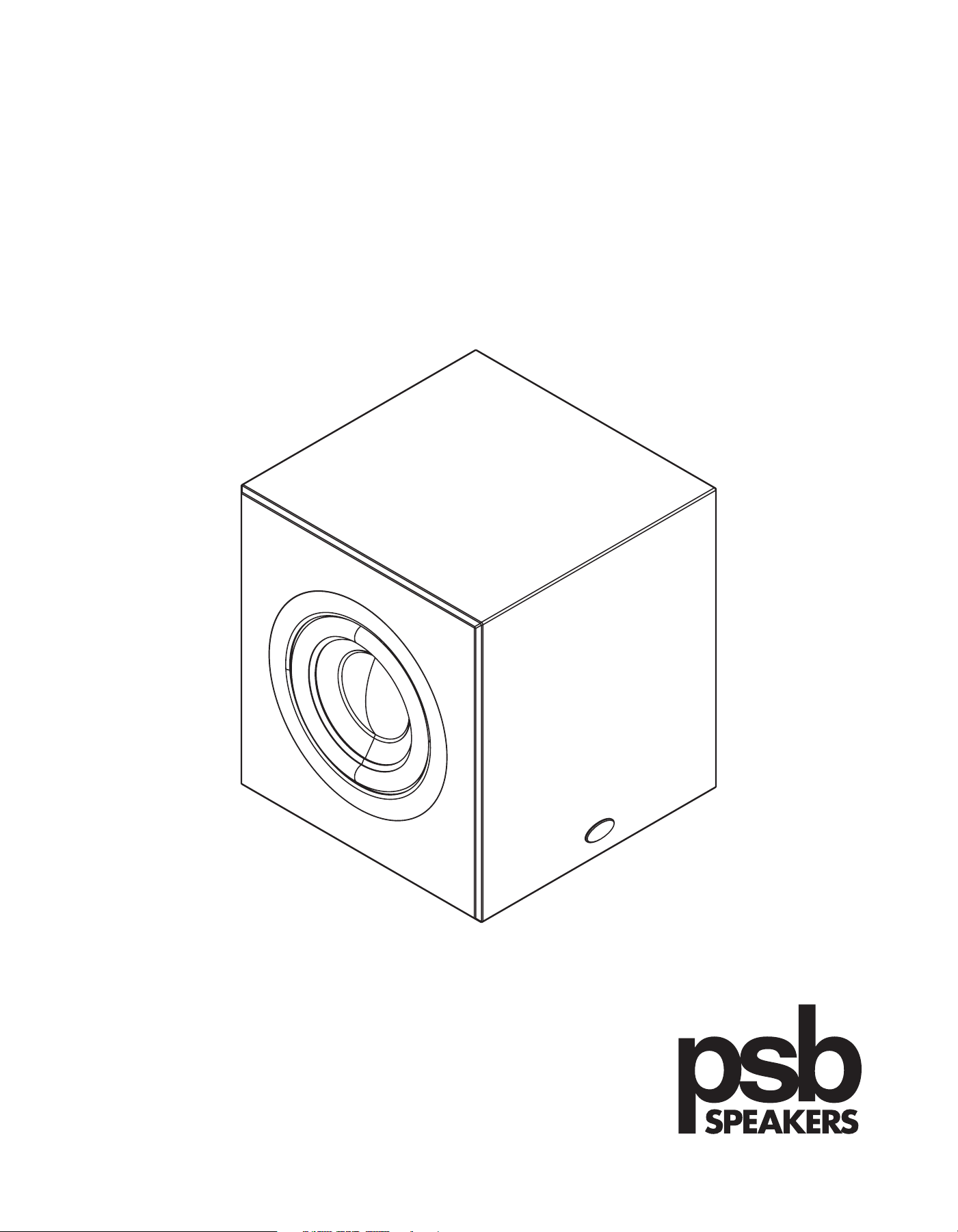
NOTES ON ENVIRONMENTAL PROTECTION
At the end of its useful life, this product must not be disposed of with regular household waste but must be returned to a
collection point for the recycling of electrical and electronic equipment. The symbol on th product, user’s manual and packaging,
point this out.
The materials can be reused in accordance with their markings. Through re-use, recycling of raw materials, or other forms of recycling of old products,
you are making an important contribution to the protaction of our enviroment.
Your local administrative ofce can advise you of the responsible waste disposal point.
Introduction
PSB subwoofers are designed to provide the attest possible frequency response, full bass extension, low distortion and high output. Beyond these characteristics
there are a few other parameters that we feel are very important in the design of a subwoofer. First and foremost, a PSB subwoofer must be musical. A
subwoofer should also have the ability to play musically even when overloaded or stressed. For this reason PSB subwoofers incorporate limiting circuitry
preventing audible overload while remaining true to the dynamics of the music. This circuitry combines peak limiting circuits that hold amplier signal swing to
the point just short of the amplier’s clipping, with compression circuitry that will reduce the amplier’s gain.
Managing heat dissipation is challenging with today’s greater power demands. Where suitable, PSB subwoofers use the latest implementation of direct digital
power amplication, that maintains maximum efciency and low THD under all conditions.
PSB woofers are always designed to reduce mechanical noise and prevent harsh sounds at the excursion extremes. Cabinets and ampliers are designed to
prevent air leaks, which can contribute minute amounts of noise. All of our designs are exhaustively tested to survive 15 continuous hours of being driven to
maximum output.
We hope that our attention to detail results in countless hours of pleasant entertainment. Please take the time to read the following sections about the placement
of your subwoofer, its connections and adjustments. Enjoy.
Contents
X 4X 2
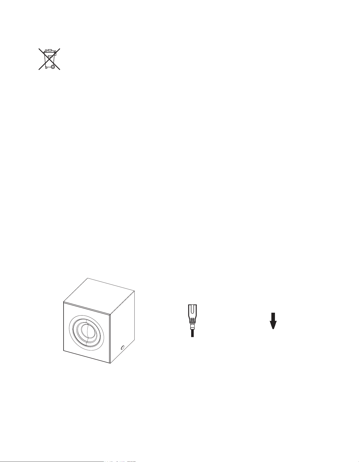
Quick Start Instructions
AMPLIFIER BP7
BP7
BP7AMPLIFIER
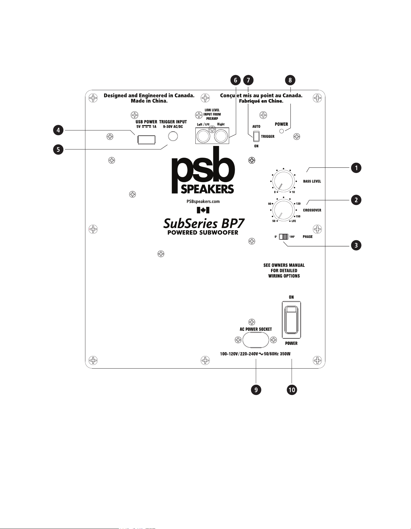
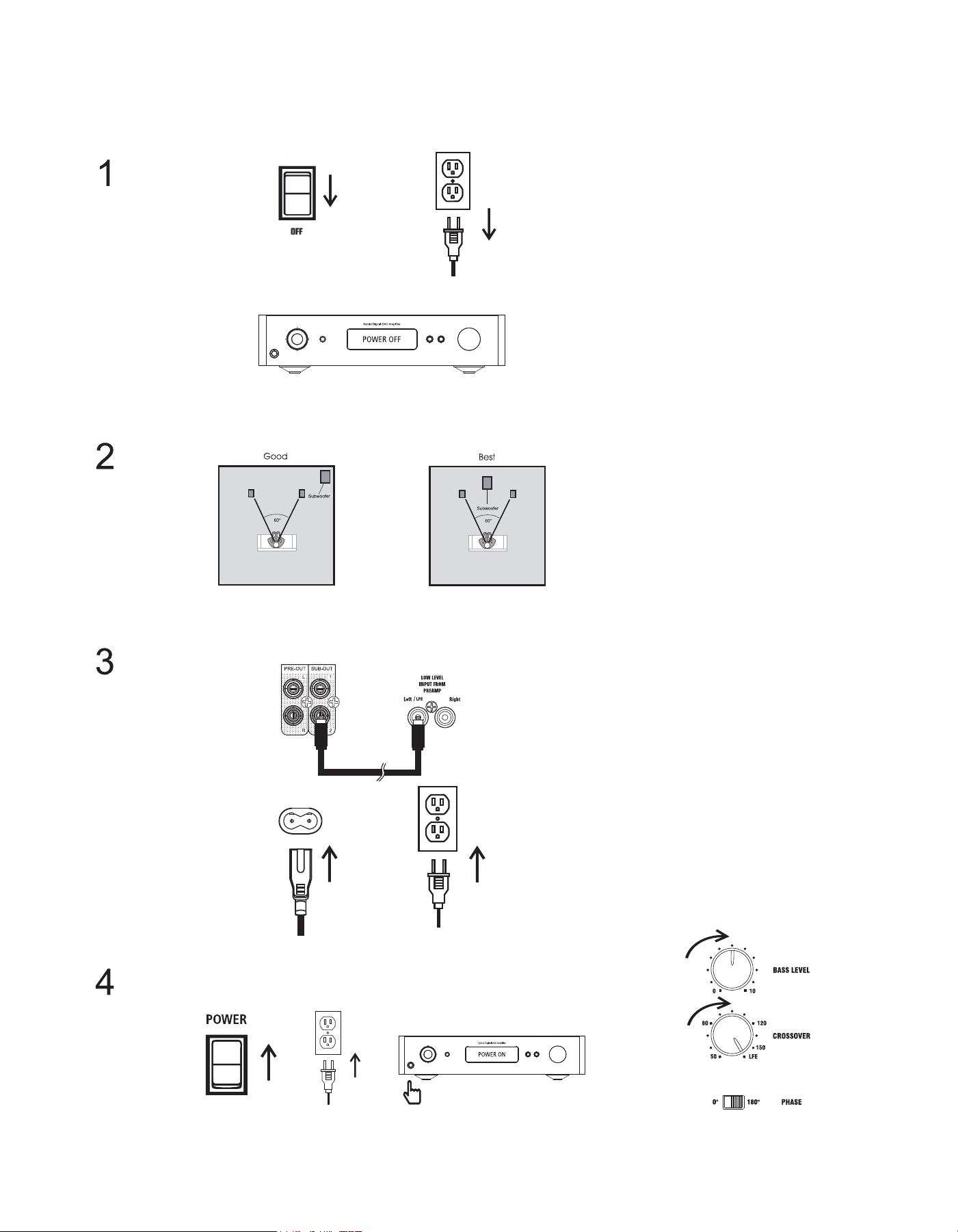
1 BASS LEVEL
Adjust the output level of the subwoofer. This is not intended as a day-to-day volume control.
2 CROSSOVER
Adjust the upper limit of the subwoofer’s frequency range with a continuous variable range from 50Hz to 150Hz. This allows
for precise matching of subwoofer bass reproduction with the main (left and right) stereo speakers. When using LFE input, set
the dial to LFE.
3 PHASE
Select the phase of the subwoofer output, selecting between in-phase (0 degrees) or out-of-phase (180 degrees). This adjustment compensates
for the low to mid-bass acoustic effects that vary based on placement locations and listening rooms.
Connections and Controls

4 USB POWER
Connect Wireless Subwoofer signal receiver.
5 TRIGGER INPUT
Wirelessly triggers the activation or deactivation of the subwoofer by connecting a 12V signal from an electronic component.
6 LOW LEVEL INPUT FROM PREAMP
Use to connect line level full range left and right output from external preamplier, integrated amplier or receiver.
LFE / Subwoofer Input
Connect LFE/Subwoofer output from external preamplier, integrated amplier or receiver.
Note:
Set LFE/Subwoofer signal from within the component and not by the subwoofer control. Set subwoofer control as follows:
• Phase: 0
• Crossover: LFE
• Bass: 8
7 SUBWOOFER ACTIVATION SWITCH
Three-way switch setting for activating the subwoofer.
Auto: Subwoofer is activated when an audio signal is detected.
Trigger: Subwoofer is activated when there is 12V Trigger input.
On: Subwoofer is always active.
8 SUBWOOFER STATUS LIGHT
Two color LED power indicator.
Red: Standby mode
Green: Active mode
Notes:
• Subwoofer will stay active for approximately 15 minutes with no audio signal.
•
Verify the electrical integrity of the fuse located within the back panel's AC Power Socket if the subwoofer is powered on but displays no LED light
9 AC POWER SOCKET
10 POWER SWITCH
Switch ON/OFF the subwoofer’s internal amplier.
Supplies AC power to the PSB subwoofer. Connect the supplied power cord to the AC Power socket. Plug the other end of the power cord into any
standard wall outlet. Utilize the same receptacle as the rest of the system or another on the same electrical circuit to prevent ground hum.
or any sound.
4 USB POWER
Connect Wireless Subwoofer signal receiver.
5 TRIGGER INPUT
Wirelessly triggers the activation or deactivation of the subwoofer by connecting a 12V signal from an electronic component.
6 LOW LEVEL INPUT FROM PREAMP
Use to connect line level full range left and right output from external preamplier, integrated amplier or receiver.
LFE / Subwoofer Input
Connect LFE/Subwoofer output from external preamplier, integrated amplier or receiver.
Note:
Set LFE/Subwoofer signal from within the component and not by the subwoofer control. Set subwoofer control as follows:
• Phase: 0
• Crossover: LFE
• Bass: 8
7 SUBWOOFER ACTIVATION SWITCH
Three-way switch setting for activating the subwoofer.
Auto: Subwoofer is activated when an audio signal is detected.
Trigger: Subwoofer is activated when there is 12V Trigger input.
On: Subwoofer is always active.
8 SUBWOOFER STATUS LIGHT
Two color LED power indicator.
Red: Standby mode
Green: Active mode
Notes:
• Subwoofer will stay active for approximately 15 minutes with no audio signal.
• Verify the electrical integrity of the fuse located within the back panel's AC Power Socket if the subwoofer is powered on but displays no LED light
9 AC POWER SOCKET
10 POWER SWITCH
Switch ON/OFF the subwoofer’s internal amplier.
Room Acoustics
If you are critical about low-frequency response, there’s quite a bit of useful experimentation you can do, especially in combination with the crossover,
level, and phase controls of our subwoofers.
Begin by considering the size of the listening room. The larger the volume of air a speaker must move, the more acoustic output is required to achieve the
sound levels you want. In smaller rooms, sound attenuation tends to be offset by reinforcement from wall reections. In larger spaces, sound has to travel
to reach the reecting surfaces and then to your ears, which means it has to be louder to begin with. With traditional full-range speakers, that involves
properly matching amplier power, speaker sensitivity, impedance and power handling. Most of the power goes to reproducing bass, so using powered
subwoofers and separate midrange/treble satellites allows for a conservative draw on power from your main amplier, while ensuring a good match
between the low-frequency amplier and the woofer.
After size, the most important aspect of a listening room is its shape. In any room, sound reects off the walls, ceiling, and oor. If the distance between
two opposite parallel surfaces is a simple fraction of the wavelength of a particular frequency, notes of that frequency will bounce back and forth in perfect
phase - an effect called a standing wave or room mode. At some point in the room, this note will be reinforced substantially; at others it will cancel out
almost entirely. If the prime listening seat is placed at either of these locations, the note will be a horrible boom or virtually non- existent. Almost all rooms
are susceptible to some standing waves at low frequencies, but careful positioning of the speakers and the listening seat can minimize the effects. The only
way to nd out what works best is by experimentation.
Speaker positioning may be fairly limited in your room to still get proper imaging, and some of these positions may still result in standing waves. Use of a
subwoofer or two makes this more controllable. Positioning of the bass speakers has almost no impact on imaging, so a subwoofer can be positioned with
only standing waves in mind.
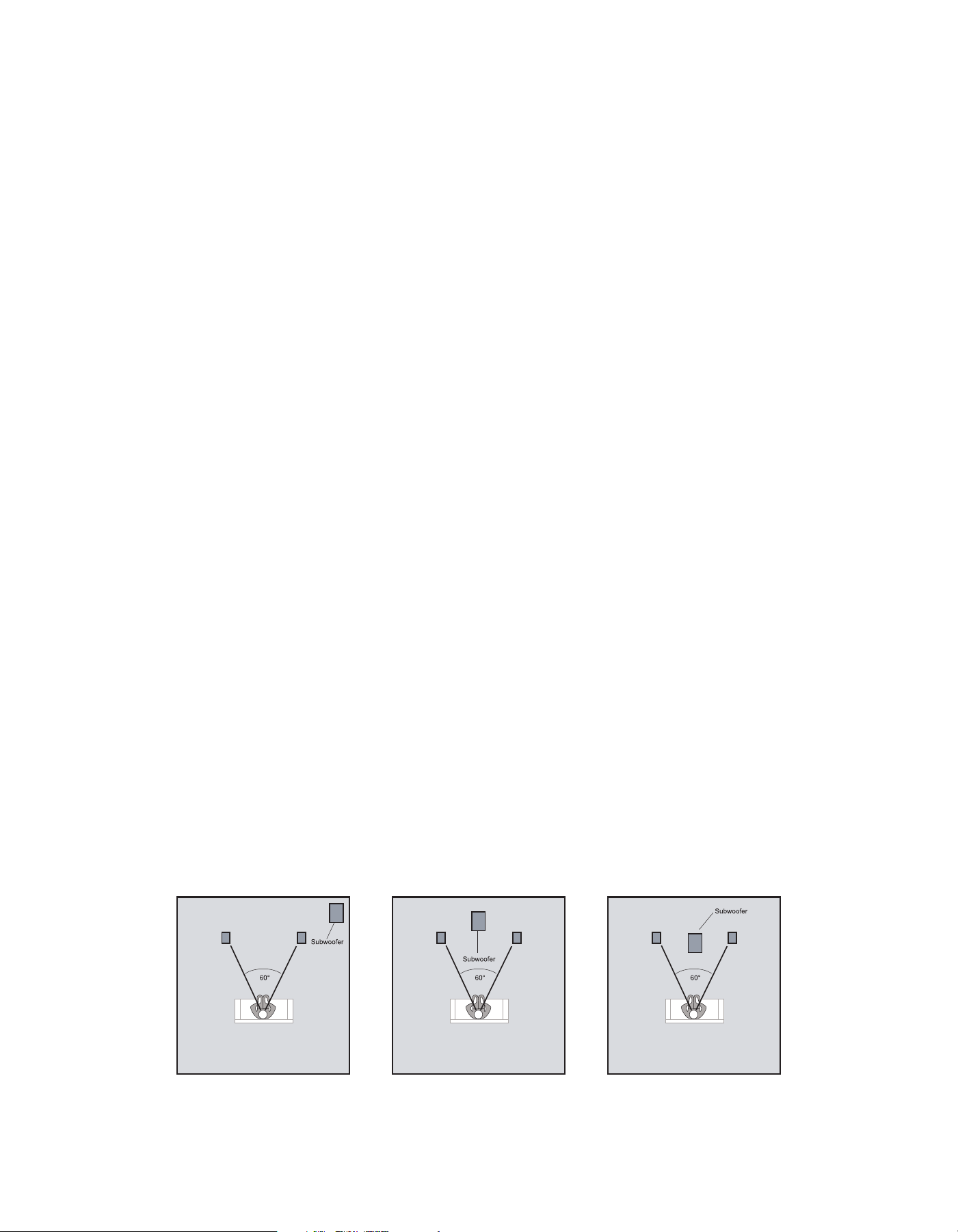
Subwoofer Placement
The loudest bass output from a subwoofer comes from corner placement. The outward aring of walls from a corner focuses low frequencies, giving them
no place to go but toward the listener. In the case of subwoofers, there is no penalty in overall balance for this maximal bass since your main speakers can
be located elsewhere. In most cases, there should be plenty of bass from corner placement.
If you are seated in a null spot where sound from the subwoofer is cancelled or diminished by out-of-phase reections, you will have to move either the
subwoofer or your listening position until you get the desired bass. Flipping the phase control 180 degrees sometimes may make a difference, especially if
the null is a product of cancellations caused by interaction with low frequencies from your main speakers. If the opposite is happening, where direct and
reected bass waves converge in phase and produce too strong a peak at your listening position, you can change position or change your sub’s level
control (or possibly the crossover frequency chosen).
The best method for positioning a subwoofer is to put the subwoofer in your listening chair, then play music with lots of bass through the system
(something with steady low frequencies or continuous test tones). Move around the room and note where the bass sounds best; if you place the
subwoofer in that
location, you should achieve the same bass performance. This test only works if you have your ears at the same height as
where the subwoofer will be, so you may have to get down low. A recommended starting point for the placement of this subwoofer would
be in either of the front corners of the room, on either side of the main speakers.
Most bass output;
least even bass response
Moderate bass output;
more even bass response
Lowest bass output;
most even bass response

Multiple Subwoofers - Why Two Subs Are Better Than One
Sometimes the listening room is not conducive to achieving satisfying amounts or the quality of bass. There are rooms with troublesome dimensions, especially
those that are more cubical. In such a case, two subwoofers placed carefully to work with each other are recommended to handle acoustical anomalies. This
can also be applied when the problem is too much, or too uneven, bass. The overall system benets from each subwoofer correcting the acoustic problems
caused by the other. The two subwoofers do not have to be identical.
A very good starting point for positioning two subwoofers is to place one each in the center of opposing walls. Experimenting with positioning as previously
described should be used for determining the location of the second subwoofer, except in this instance one is listening for the minimum amount of bass
output.
Control Settings
Once a reasonably smooth response has been achieved by careful positioning of the subwoofers, the overall performance can be ne-tuned by
means of the speaker controls. The crossover frequency controls the upper limit of the subwoofer’s frequency range. This should be set high
enough to overlap the low frequency cutoff of the satellite speakers, but not high enough to localize specic sounds from the subwoofer.
If the frequency response of your satellite speakers is such that the subwoofer’s crossover frequency controls must be set higher than about
80Hz to avoid gaps in the overall system response, then you might be able to localize specic sounds from the subwoofer. These sounds may
seem to come from beside or behind you. One solution is to ensure the subwoofer is in the front of the listening area; another is to use
multiple subwoofers to diffuse such sounds.
Subwoofers also offer a phase control so the upper frequencies produced will not cancel out the lower frequencies of the satellites. Adjustment
of this control can have a great effect on spectral smoothness in the crossover area. Phase changes with frequency, however, so these controls
may need readjusting every time you vary the cutoff frequency.
The overall level of the subwoofer’s output may also be adjusted. To gain smooth response, be careful not to set this too high.
Set-up Calibration
1 The following procedure assumes your PSB subwoofer is installed and connected. If possible, work in a team with another person:
2 Set Subwoofer Bass Level to 0, Crossover Control to 50Hz. Set any loudness, bass and treble, and/or equalizer controls on your
3 Play a familiar audio or video soundtrack that includes substantial deep-bass content over an extended section.
4
5
one listening, one making subwoofer-control adjustments.
preamplier or integrated amplier or receiver, or other components, to their nominal (midpoint or off) positions.
Slowly turn the Subwoofer Crossover clockwise to reach the best mid-bass blend with your main left and right speakers. This will be the
point at which the upper bass retains solid impact and fullness. Boom or muddiness is the result if the control is too high. A
thin,“reedy” quality to the mid-bass such as deep male voices (FM announcers; Darth Vader) is the result if the control is too low.
Adjust the Phase control between 0° and 180°, leaving it in the position that yields the fullest low to mid bass output. You will now
probably want to repeat steps 3 and 4 to double-check the subwoofer blend.
Cycling through steps 3 and 4 several times with slightly different settings of both the Subwoofer Bass Level and Crossover control will
help you get the most musical performance from your PSB Subwoofer and your system. The best combination is that which yields the
most solid very-low-bass sounds, without mid-bass boom or a gap in response between the subwoofer and the main speakers.
Gradually turn the Subwoofer Bass Level clockwise until you achieve natural balance between the subwoofers deep-bass output and
your main left and right loudspeakers.

Troubleshooting
Issue Action
Ensure the power cord is connected to the subwoofer and plugged into a live AC outlet.
Ensure the power cord is connected to the subwoofer and plugged into a live AC outlet.
All PSB subwoofers utilize signal sensing auto on/off circuitry. If no signal is sent to the
subwoofer, it will not power up and the on/standby indicator will remain red. When using the
subwoofer output of a receiver or processor, no signal may be immediately present in this
output. The subwoofer will only power up when bass signal appears at the subwoofer input.
If the low level cable connection is poor or has been severed, the subwoofer will not power
up. Swap cables to determine if this is the source of the problem.
To ensure the problem is not associated with the subwoofer, rapidly disconnect and
connect the subwoofer low level. If the subwoofer on/standby indicator then illuminates
green, the receiver/processor/amp may not be sending a signal to the subwoofer. When
driving the low level inputs from a subwoofer output, ensure the receiver/processor is
correctly congured to provide signal at the subwoofer output.
Further, a red on/standby indicator can be caused by an overvoltage or undervoltage condition
at the AC outlet. The indicator will also turn red during abnormal operating conditions such as
excessive internal temperature or a presence of DC voltage at the amplier output, in which
case the subwoofer needs to be serviced.
Lower Bass Level if the subwoofer begins to sound distorted to determine if playback at a lower
level solves the problem. If a slight reduction in level solves the problem, then the subwoofer
level was too high. If the distorted sound remains at a low level, driver(s) may be damaged.
Hum that appears when using the subwoofer’s low level input(s) is usually caused by using an
inferior, damaged, exceptionally long low level cable or cables routed near high current wiring/
appliances. Replace/shorten the low level cable connecting the subwoofer to the source equip-
ment (receiver or processor). Low level cable runs of longer than 20 feet may require the use of
a line driver (not available from PSB).
Hum heard when using the subwoofer’s high level input(s) is usually caused by an intermit-
tent or missing positive or negative connection. Ensure there is a good connection between
all speaker wires connecting the subwoofer and receiver/amplier.
Decreasing the volume control of the subwoofer and increasing the volume control of the
receiver/processor/amplier subwoofer output can sometimes reduce hum to an acceptable level.
I.
II.
I.
II.
III.
I V.
I.
I.
II.
III.
No sound/Status light not lit
No sound/Status light
remains red
Sounds distorted
Hum
The Subwoofer Bass Level and Crossover Control are interactive. Raising the latter while lowering the former can have the effect of
extending deep-bass response somewhat, with a small sacrice in overall loudness capability (this will still be well beyond the full-range
loudness capability of most systems). In general, for well-recorded acoustic music the lowest Subwoofer Cut-Off Frequency setting that
yields a smooth transition between subwoofer and main speakers is often the best choice, and will promote deeper low-bass extension.
Note: The Subwoofer Bass Level is not a bass-boost or volume control. It is a set-and-forget adjustment, not intended for day-to-day
adjustment. Use your preamplier or receiver/integrated amp tone controls to modify program tonal balance.

Protecting your Investment
For long lasting enjoyment of your PSB product, you should respect their limits and avoid excessive volume levels for music or movie
playback. Excessive volume levels can damage all types of speakers. If your speakers are pushed to excessive volume levels, they could be
driven into “clipping”, which may result in severe and/or permanent damage.
If listening to your speakers at loud levels, listen carefully for any signs of harsh, distorted midrange and diminishing precision. If detected,
turn the volume down immediately.
NEVER TEST PEAK LISTENING LEVELS OF YOUR SPEAKERS BY TURNING THE VOLUME TO THE MAXIMUM LEVEL.
Care and Cleaning
For safe, sanitary use, it is essential to maintain and clean your speakers periodically. However, excessive cleaning may cause damage and
jeopardize the longevity of the product. When not in use, avoid storing in extreme hot or cold temperatures and humidity, and avoid
exposure to liquids.
Packaging
We highly recommend retaining all product packaging for any necessary transporting. To transport, carefully place the speakers into their
original packaging and close each panel.
Cabinet Care
PSB cabinets have varying materials and nishes, including wood veneers, vinyl, anodized aluminum, and high gloss, and should be treated
with the same care you would with similar nishes such as on furniture. Dust lightly with a soft cloth, avoiding abrasive materials that will
cause permanent damage to the cabinet. If necessary, wipe carefully with a cloth slightly dampened with water-based cleaner to remove
heavy soil.
Drivers and Port Care
During light cleaning, avoid touching speaker diaphragms as it could cause permanent damage to the tweeter and/or drivers. To clean the
driver ports, we suggest using a lint-free cloth.
Environmental Protection
At the end of its useful life, this product must be returned to a collection point for the recycling of electrical and electronic equipment. Do
not dispose with regular household waste.
See your dealer if you require service. Authorized PSB dealers are equipped to handle almost all problems. You may locate your nearest PSB
authorized dealer on-line at www.psbspeakers.com. If the problem is not resolved, please contact us, providing the model name, serial
number, date of purchase, dealer name, and a full description of the problem.
We appreciate your purchase, and hope this owner’s guide helps you enjoy the exceptional performance that PSB speaker systems have to
offer. We wish you many years of enjoyable listening!

Specifications
FREQUENCY RESPONSE
On Axis @ 0° ± 3dB 30Hz -150Hz
LF Cutoff -10dB 25Hz
AMPLIFIER POWER (Internal Amplier)
350W
Analog Devices DSP & Texas Instrument Class-D Amp
Red: Standby
Green: On
T10AL 250V
ACOUSTIC DESIGN
Woofer (Nominal) 6.5” (152 mm)
Carbon Fibre Cone
High Density Rubber Surround
Crossover
Design Type
1 1/2” (38 mm) Voice-Coil
36 oz (1030 g) Magnet
Steel Basket
Variable: 50Hz -150Hz
LFE setting (350Hz)
Sealed
SIZE (W x H x D)
Net Dimensions 10.60” x 11.4” x 10.6”
(270 x 290 x 270 mm)
Gross DimensionsGr 10.60” x 11.8” x 11.6”
(270 x 300 x 295 mm)
WEIGHT
Net Weight 26.5lbs (12 kg)
Shipping Weight 30 lbs (13.6kg)
FINISH
Satin Black, Satin White
FEATURES
Bass Level
Crossover
Phase Switch
Low level input
Gold-plated Stereo RCAs
Trigger Input
Universal Voltage
(100V-240V, 50/60Hz)
North America and European power cords supplied
Auto On/Standby
0.5W Standby
Continuous Power
Design
LED Indicator
AC Fuse
*Gross dimensions include /_knobs /_speaker terminals / feet
Controls
Connections
Other
Energy Star Compliance
NOTE
When using with an LFE signal, crossover frequency control has to be set to max (LFE).

PSB Speakers
633 Granite Court Pickering, Ontario. L1W 3K1
CANADA
www. psbspeakers. com
888-772-0000
(905) 831-6555
Fax: 905-831-6936