MODEL NUMBER
USER MANUAL
Warning notices: Before using this product, please read this manual carefully and keep it for future reference.
The design and specifications are subject to change without prior notice for product improvement.
Consult with your dealer or manufacturer for details.
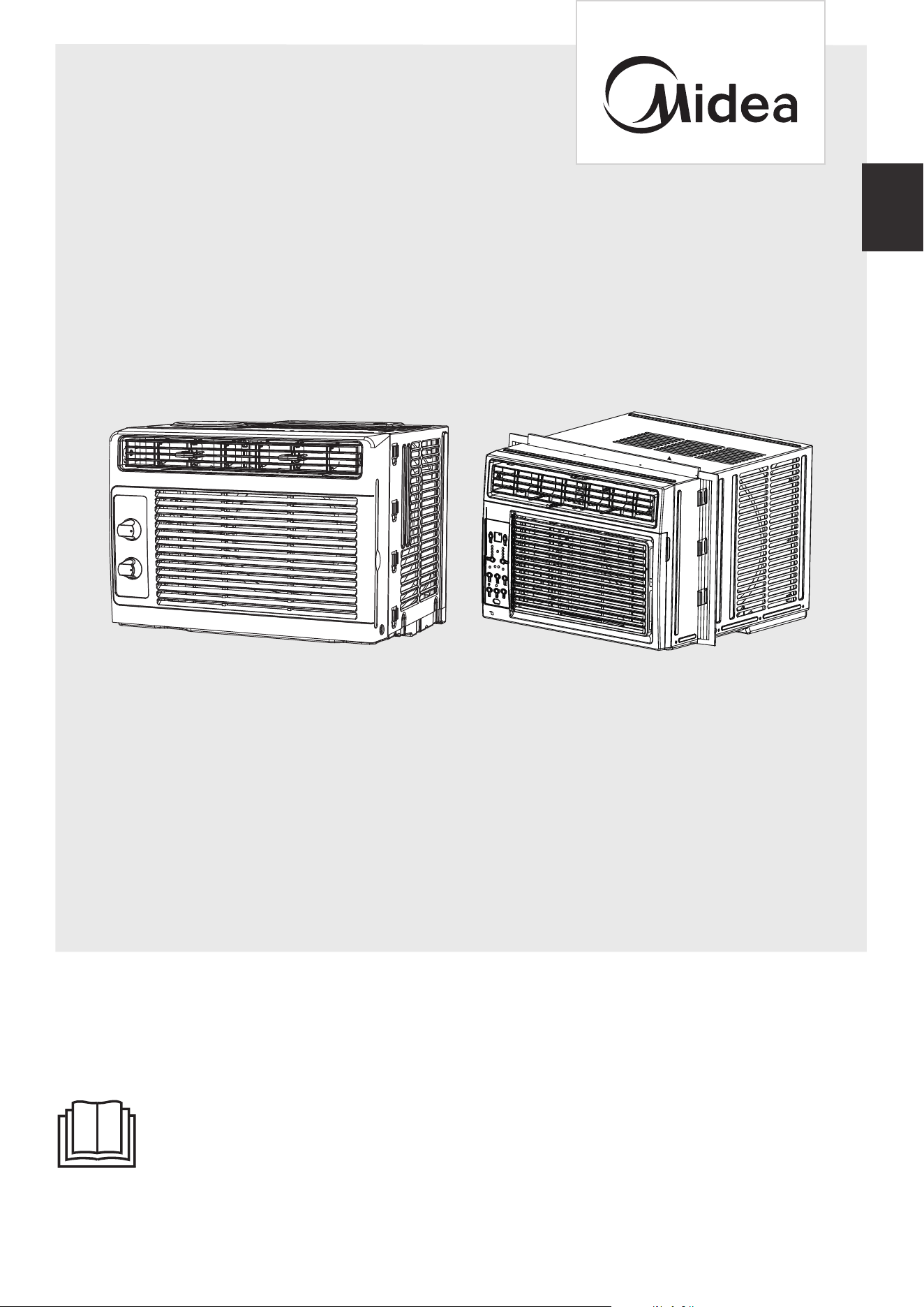
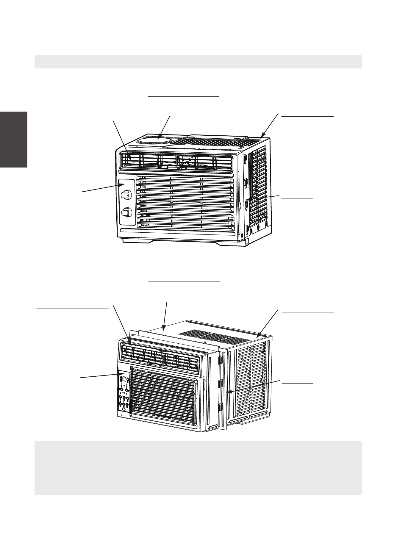
The diagram above is just for reference. Please take the appearance of the actual product as the standard.
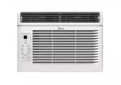
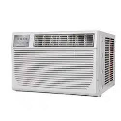
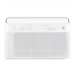
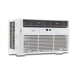
WINDOW TYPE ROOM AIR CONDITIONER
en
MAW05M1WBL-TMAW05M1WWT-T
MAW05R1WWT-T
MAW06R1WWT-T
MAW05R1WBL-T
MAW06R1WBL-T
MAW05M1WWT-N
MAW05M1WBL-N
02
14
27
28
36
OPERATING INSTRUCTIONS
INSTALLATION INSTRUCTIONS
CARE AND CLEANING
TROUBLESHOOTING TIPS
REMOTE CONTROL INSTRUCTIONS
WARRANTY AND RETURN POLICY
THANK YOU LETTER
Thank you for choosing Midea! Before using your new Midea product, please
read this manual thoroughly to ensure that you know how to operate the
01
CONTENTS
02
03
THANK YOU LETTER
SAFETY PRECAUTIONS
Read This Manual
Inside you’ll find many helpful hints on how to use and maintain your air conditioner
properly. Just a little preventive care on your part can save you a great deal of time
and money over the life of your air conditioner. You’ll find many answers to common
problems in the troubleshooting tips - you should be able to fix most of them quickly
before calling service. These instructions may not cover every possible condition of
use, so common sense and attention to safety is required when installing, operating
and maintaining this product.
• For support, please call the Service Center at 1-866-646-4332.
• This appliance is not intended for use by people (including children) with reduced
physical, sensory or mental capabilities or lack of experience and knowledge, unless
they have been given supervision or instruction concerning use of the appliance by
a person responsible for their safety.
• Children should be supervised to ensure that they do not play with the air conditioner.
• The appliance shall be installed in accordance with national wiring regulations.
• Do not operate your air conditioner in a humid room such as a bathroom or laundry
room.
CAUTION
2
30
2
03
Explanation of Symbols
Must read the warning message.
Read Safety Precautions Before Operation and Installation
To prevent death or injury to the user or other people and property damage, the
following instructions must be followed.
Incorrect operation due to ignoring of instructions may cause death, harm or damage.
WARNING
CAUTION
This symbol indicates the possibility of property damage or serious
consequences.
This symbol indicates the possibility of personnel injury or loss of life.
SAFETY PRECAUTIONS
Safety
Precautions
04
NOTICE
The power supply cord with this air conditioner contains a current detection device designed
to reduce the risk of fire.
In the event that the power supply cord i s damaged, it can not be repaired. It must be replaced
with a cord from the manufacturer.
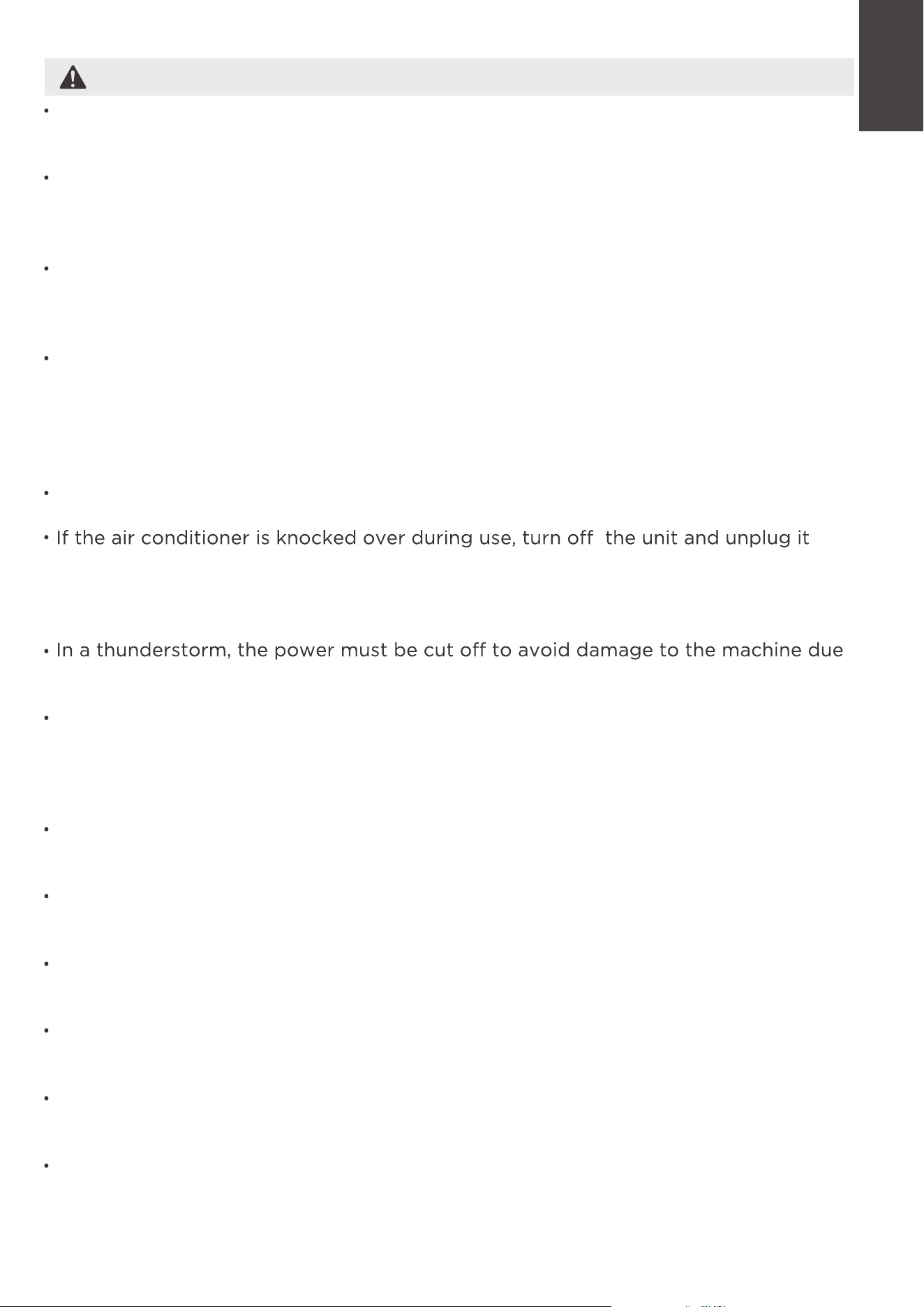
Grounding type wall receptacle
Do not, under any
circumstances, cut,
remove or bypass
the grounding prong.
Power supply cord with 3-prong grounding
plug and current detection device.
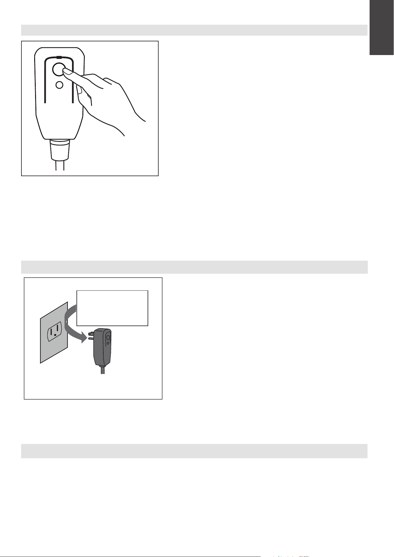
The power supply cord contains a measurement current device that senses damage to the power cord.
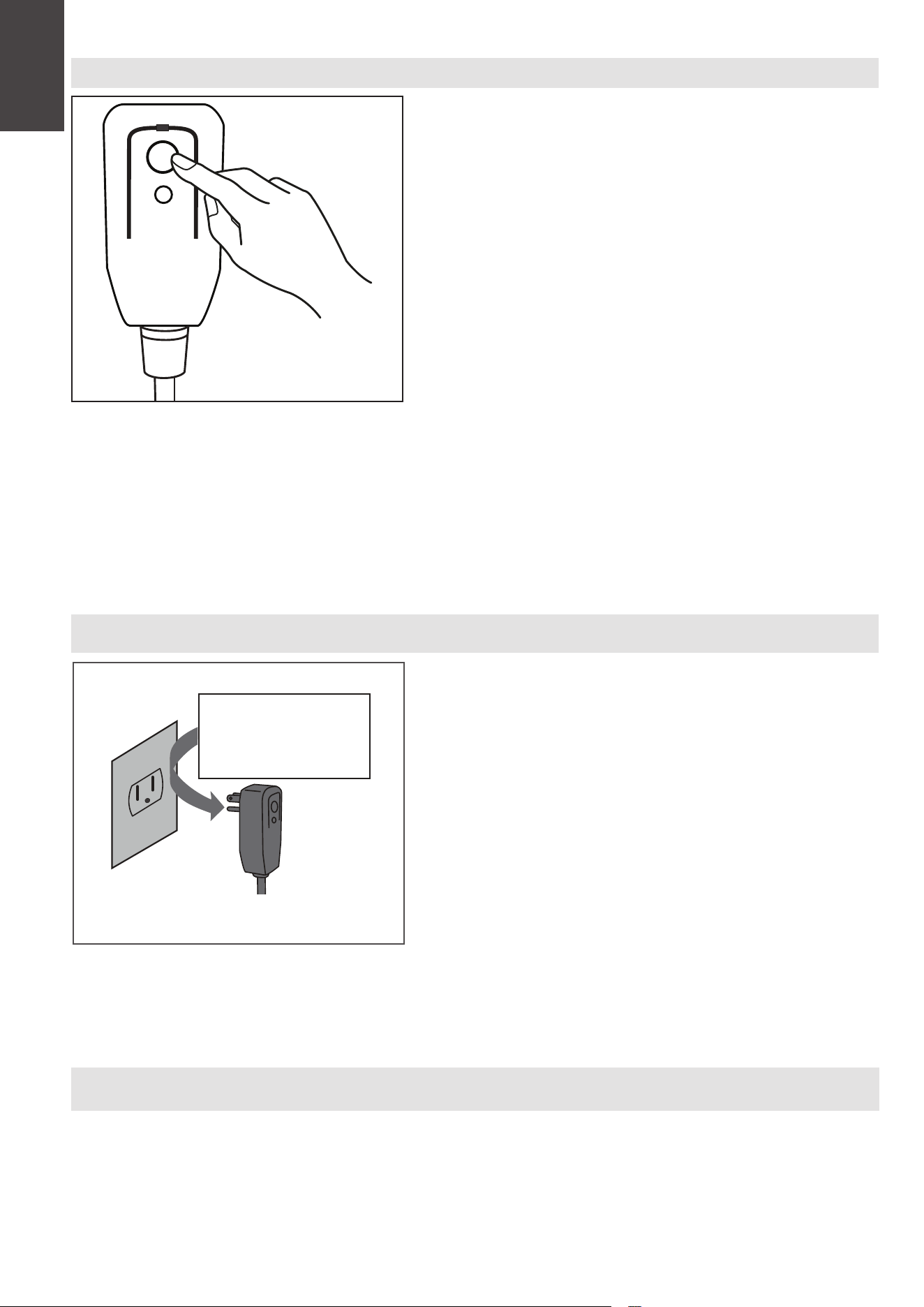
Test your power supply cord as follows:
1. Plug in the air conditioner.
2. The power supply cord will have TWO buttons on the plug head. Press the TEST button. You will
notice a click as the RESET button pops out.
3. Press the RESET Button. You will notice a click as the button engages.
4. The power supply cord is now supplying electricity to the unit. (On some products this is also
indicated by a light on the plug head.)
RESET
TEST
Plug in &
press RESET
Operation of Current Device
NOTICE
• Do not use this device to turn the unit on or off.
• Always make sure the RESET button is pushed in for correct operation.
• The power supply must be replaced if it fails to reset when either the TEST button
is pushed, or it can not be reset. Please contact Customer Service.
Safety
Precautions
05
WARNING
Installation must be performed according to the installation instructions. Improper
installation can cause water leakage, electrical shock, or fire.
Use only the included accessories and parts, and specified tools for the installation.
Using nonstandard parts can cause water leakage, electrical shock, fire, and injury
or property damage.
Make sure that the outlet you are using is grounded and has the appropriate
voltage. The power cord is equipped with a three-prong grounding plug to protect
against shock. Voltage information can be found on the nameplate of the unit.
Do not touch the unit with wet or damp hands or when barefoot.
from the main power supply immediately. Visually inspect the unit to ensure there
is no damage. If you suspect the unit has been damaged, contact a technician or
customer service for assistance.
to lightning.
Your air conditioner should be used in such a way that it is protected from moisture.
e.g. condensation, splashed water, etc. Do not place or store your air conditioner
where it can fall or be pulled into water or any other liquid. Unplug immediately if
it occurs.
Install the unit on a flat, sturdy surface. Failure to do so could result in damage or
excessive noise and vibration.
The unit must be kept free from obstruction to ensure proper function and to
mitigate safety hazards.
Do not modify the length of the power cord or use an extension cord to power the
unit.
Do not share a single outlet with other electrical appliances. Improper power
supply can cause fire or electrical shock.
Do not install your air conditioner in a wet room such as a bathroom or laundry room.
Too much exposure to water can cause electrical components to short circuit.
Do not install the unit in a location that may be exposed to combustible gas, as this
could cause fire.
Safety
Precautions
Your unit must be used in a properly grounded wall receptacle. If the wall
receptacle you intend to use is not adequately grounded or protected by a time
delay fuse or circuit breaker(the fuse or circuit breaker needed is determined by
the maximum current of the unit. The maximum current is indicated on the
nameplate located on unit), have a qualified electrician install the proper receptacle.
06
CAUTION
The unit has wheels to facilitate moving. Make sure not to use the wheels on thick
carpet or to roll over objects, as these could cause tipping.
Do not operate a unit that it has been dropped or damaged.
The appliance with electric heater shall have at least 1 meter space to the
combustible materials.
All wiring must be performed strictly in accordance with the wiring diagram located
inside of the unit.
The unit's circuit board(PCB) is designed with a fuse to provide overcurrent
protection. The specifications of the fuse are printed on the circuit board, such as:
T 3.15A/250V, etc.
When the water drainage function is not in use, keep the upper and the lower drain
plug firmly to the unit to get rid of choking. When the drain plug is not in use, keep
it carefully to prevent children from choking.
This appliance is not intended for use by persons (including children) with reduced
physical, sensory or mental capabilities or lack of experience and knowledge, unless
they have been given supervision or instruction concerning use of the appliance by
a person responsible for their safety. Children should be supervised to ensure that
they do not play with the appliance. Children must be supervised around the unit at
all times.
If the supply cord is damaged, it must be replaced by the manufacturer,its service
agent or similarly qualified persons in order to avoid a hazard .
Do not use this product for functions other than those described in this instruction
manual.
Before cleaning, turn off the power and unplug the unit.
Disconnect the power if strange sounds, smell, or smoke comes from it.
Do not press the buttons on the control panel with anything other than your fingers.
Do not remove any fixed covers. Never use this appliance if it is not working
properly, or if it has been dropped or damaged.
Do not operate or stop the unit by inserting or pulling out the power cord plug.
Do not use hazardous chemicals to clean or come into contact with the unit. Do not
use the unit in the presence of inflammable substances or vapour such as alcohol,
insecticides, petrol,etc.
Prior to cleaning or other maintenance, the appliance must be disconnected from
the supply mains.
Safety
Precautions

07
Do not remove any fixed covers. Never use this appliance if it is not working properly,
or if it has been dropped or damaged .
Do not run cord under carpeting. Do not cover cord with throw rugs, runners, or
similar coverings. Do not route cord under furniture or appliances. Arrange cord away
from traffic area and where it will not be tripped over.
Do not operate unit with a damaged cord, plug, power fuse or circuit breaker. Discard
unit or return to an authorized service facility for examination and/or repair.
To reduce the risk of fire or electric shock, do not use this fan with any solid-state
speed control device.
The appliance shall be installed in accordance with national wiring regulations.
Contact the authorized service technician for repair or maintenance of this unit.
Do not cover or obstruct the inlet or outlet grilles.
Always transport your air conditioner in a vertical position and stand on a stable, level
surface during use.
Always contact a qualified person to carry out repairs. If the damaged power supply
cord must be replaced with a new power supply cord obtained from the product
manufacturer and not repaired.
Hold the plug by the head of the power plug when taking it out.
Turn off the product when not in use.
Safety
Precautions
08
Servicing shall only be performed as recommended by the equipment manufactur-
er. Maintenance and repair requiring the assistance of other skilled personnel shall
be carried out under the supervision of the person competent in the use of flamma-
ble refrigerants.
DO NOT modify the length of the power cord or use an extension cord to power
the unit.
DO NOT share a single outlet with other electrical appliances. Improper power
supply can cause fire or electrical shock.
Please follow the instruction carefully to handle, install, clear, service the appliance
to avoid any damage or hazard.
WARNING:
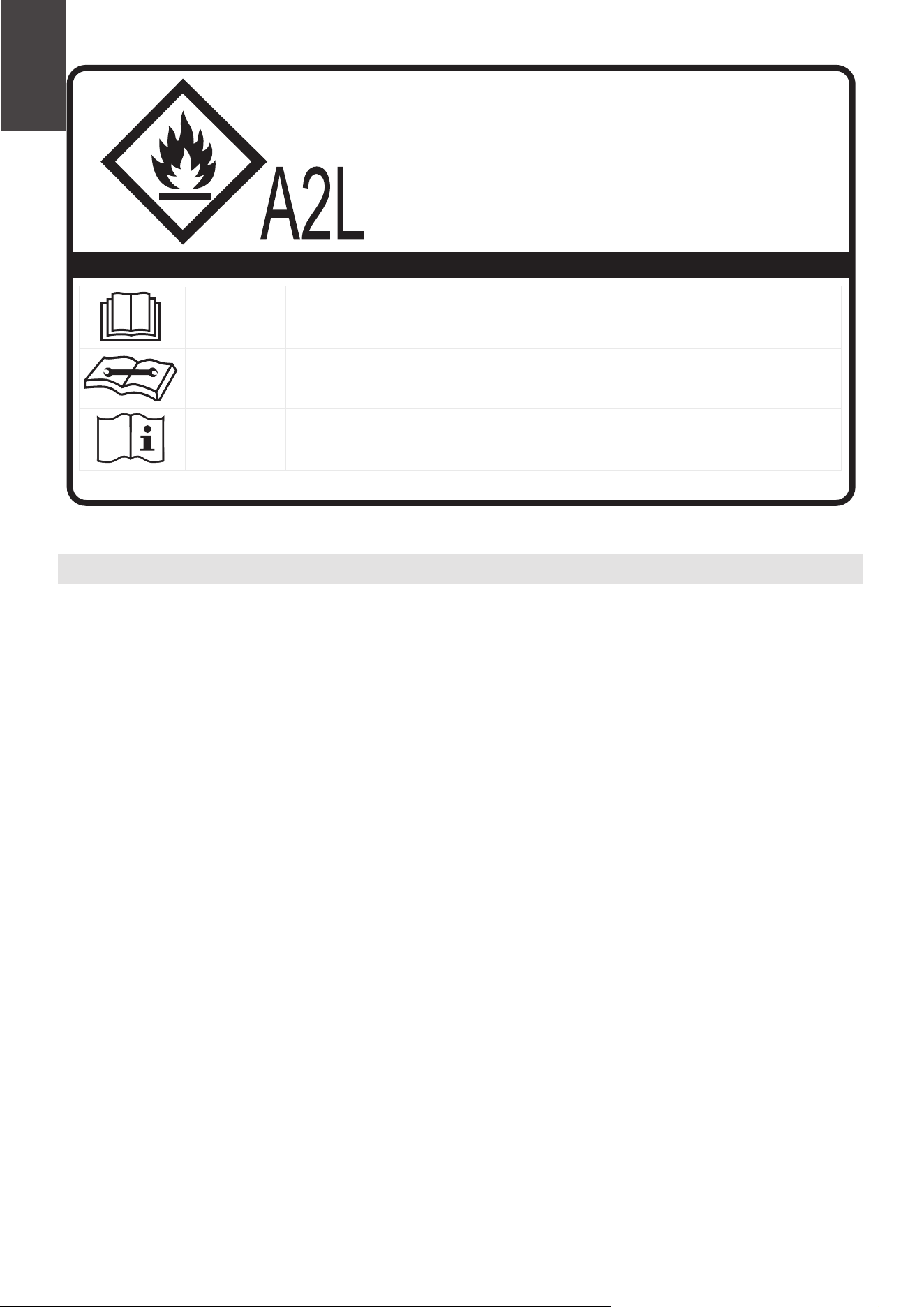
Explanation of symbols displayed on the unit
CAUTION
This symbol shows that the operation manual should be read carefully.
CAUTION
This symbol shows that a service personnel should be handling this equipment with
reference to the installation manual.
CAUTION
This symbol shows that information is available such as the operating manual or
installation manual.
•
•
•
CAUTION:
Risk of fire
flammable materials
IMPORTANT NOTE: Read this manual
carefully before installing or operating
your new appliance unit.
Make sure to save this manual for future
reference.
Safety
Precautions
•
Flammable Refrigerant R32 is used within appliance.
• When maintaining or disposing the appliance, the refrigerant (R32) shall be
recovered properly, shall not discharge to air directly.
• Compliance with national gas regulations shall be observed.
• Keep ventilation openings clear of obstruction.
• The appliance shall be stored so as to prevent mechanical damage from occurring.
• A warning that the appliance shall be stored in a well-ventilated area where the
room size corresponds to the room area as specified for operation.
• Any person who is involved with working on or breaking into a refrigerant circuit
should hold a current valid certificate from an industry-accredited assessment
authority, which authorises their competence to handle refrigerants safely in
accordance with an industry recognised assessment specification. All training
shall follow the ANNEX HH requirements of UL 60335-2-40 4th Edition.

09
Examples for such working procedures are:
• breaking into the refrigerating circuit;
• opening of sealed components;
• opening of ventilated enclosures.
• No open fire or device like switch which may generate spark/arcing shall be
around appliance to avoid causing ignition of the flammable refrigerant used.
Please follow the instruction carefully to store or maintain the appliance to
prevent mechanical damage from occurring.
• Do not use means to accelerate the defrosting process or to clean, other than
those recommended by the manufacturer.
• The appliance shall be stored in a room without continuously operating ignition
sources (for example: open flames, an operating gas appliance) and ignition
sources or (for example: an operating electric heater) close to the appliance.
• Do not pierce or burn.
• Be aware that the refrigerants may not contain an odour.
Safety
Precautions
1. Transport of equipment containing flammable refrigerants
See transport regulations.
2. Marking of equipment using signs
See local regulations.
3. Disposal of equipment using flammable refrigerants
See national regulations.
4. Storage of equipment/appliances
The storage of the appliance should be in accordance with the applicable
regulations or instructions, whichever is more stringent.
Prior to beginning work on systems containing flammable refrigerants, safety
checks are necessary to ensure that the risk of ignition is minimised. For repair
to the refrigerating system, the following precautions shall be complied with
prior to conducting work on the system.
Work shall be undertaken under a controlled procedure so as to minimise the
risk of a flammable gas or vapour being present while the work is being
performed.
Storage package protection should be constructed such that mechanical
damage to the equipment inside the package will not cause a leak of the
refrigerant charge. The maximum number of pieces of equipment permitted to
be stored together will be determined by local regulations.
5. Storage of packed (unsold) equipment
6. Information on servicing
1)Checks to the area
2)Work procedure
All maintenance staff and others working in the local area shall be instructed on
the nature of work being carried out. Work in confined spaces shall be avoided.
The area around the workspace shall be sectioned off. Ensure that the conditions
within the area have been made safe by control of flammable material.
3)General work area

10
Safety
Precautions
The area shall be checked with an appropriate refrigerating detector prior to
and during work, to ensure the technician is aware of potentially flammable
atmospheres. Ensure that the leak detection equipment being used is suitable
for use with flammable refrigerants, i.e. non-sparking, adequately sealed or
intrinsically safe.
4)Checking for presence of refrigerant
If any hot work is to be conducted on the refrigeration equipment or any
associated parts, appropriate fire extinguishing equipment shall be available to
hand. Have a dry powder or CO2 fire extinguisher adjacent to the charging area.
5)Presence of fire extinguisher
Ensure that the area is in the open or that it is adequately ventilated before
breaking into the system or conducting any hot work. A degree of ventilation
shall continue during the period that the work is carried out. The ventilation
should safely disperse any released refrigerant and preferably expel it externally
into the atmosphere.
7)ventilated area
Repair and maintenance to electrical components shall include initial safety
checks and component inspection procedures. If a fault exists that could
compromise safety, then no electrical supply shall be connected to the circuit
until it is satisfactorily dealt with. If the fault cannot be corrected immediately
but it is necessary to continue operation, an adequate temporary solution shall
be used.
9)Checks to electrical devices
Where electrical components are being changed, they shall be fit for the purpose
and to the correct specifications. At all times the manufacturer's maintenance
and service guidelines shall be followed. If in doubt consult the manufacturer's
technical department for assistance. The following checks shall be applied to
installations using flammable refrigerants: the actual refrigerant charge is in
accordance with the room size within which the refrigerant containing parts are
installed; the ventilation machinery and outlets are operating adequately and are
not obstructed; if an indirect refrigerating circuit is being used, the secondary
circuit shall be checked for the presence of refrigerant; marking to the equipment
continues to be visible and legible.
Markings and signs that are illegible shall be corrected; and refrigerating pipe or
components are installed in a position where they are unlikely to be exposed to
any substance which may corrode refrigerant containing components, unless the
components are constructed of materials which are inherently resistant to being
corroded or are suitably protected against being so corroded.
8)Checks to the refrigerating equipment
No person carrying out work in relation to a refrigerating system which involves
exposing any pipe work that contains or has contained flammable refrigerant
shall use any sources of ignition in such a manner that it may lead to the risk of
fire or explosion. All possible ignition sources, including cigarette smoking,
should be kept sufficiently far away from the site of installation, repairing,
removing and disposal, during which flammable refrigerant can possibly be
released to the surrounding space. Prior to work taking place, the area around
the equipment is to be surveyed to make sure that there are no flammable
hazards or ignition risks. No Smoking signs shall be displayed.
6)No ignition sources

11
7. Sealed electrical components shall be replaced.
8. Intrinsically safe components must be replaced.
9. Cabling
10. Detection of flammable refrigerants
This shall be reported to the owner of the equipment so all parties are advised.
Initial safety checks shall include: That capacitors are discharged: this shall be
done in a safe manner to avoid possibility of sparking; that there no live
electrical components and wiring are exposed while charging, recovering or
purging the system; that there is continuity of earth bonding.
Check that cabling will not be subject to wear, corrosion, excessive pressure,
vibration, sharp edges or any other adverse environmental effects. The check
shall also take into account the effects of aging or continual vibration from
sources such as compressors or fans.
Under no circumstances shall potential sources of ignition be used in the
searching for or detection of refrigerant leaks. A halide torch (or any other
detector using a naked flame) shall not be used.
The following leak detection methods are deemed acceptable for systems
containing flammable refrigerants. Electronic leak detectors shall be used to
detect flammable refrigerants, but the sensitivity may not be adequate, or may
need re-calibration. (Detection equipment shall be calibrated in a refrigerant-free
area.) Ensure that the detector is not a potential source of ignition and is suitable
for the refrigerant used. Leak detection equipment shall be set at a percentage
of the LFL of the refrigerant and shall be calibrated to the refrigerant employed
and the appropriate percentage of gas (25 % maximum) is confirmed. Leak
detection fluids are suitable for use with most refrigerants but the use of
detergents containing chlorine shall be avoided as the chlorine may react with
the refrigerant and corrode the copper pipe-work. If a leak is suspected, all
naked flames shall be removed/ extinguished. If a leakage of refrigerant is found
which requires brazing, all of the refrigerant shall be recovered from the system,
or isolated (by means of shut off valves) in a part of the system remote from the
leak. Removal of refrigerant shall be according to Removal and evacuation.
Safety
Precautions
11.Removal and evacuation
When breaking into the refrigerant circuit to make repairs—or for any other
purpose - conventional procedures shall be used. However, for flammable
refrigerants it is important that best practice be followed, since flammability is
a consideration. The following procedure shall be adhered to:
-Safely remove refrigerant following local and national regulations;
-Evacuate;
-Purge the circuit with inert gas (optional for A2L);
-Evacuate (optional for A2L);
-continuously flush or purge with inert gas when using flame to open circuit; and
-open the circuit.
The refrigerant charge shall be recovered into the correct recovery cylinders if
venting is not allowed by local and national codes. For appliances containing
flammable refrigerants, the system shall be purged with oxygen-free nitrogen to
render the appliance safe for flammable refrigerants. This process might need to
be repeated several times. Compressed air or oxygen shall not be used for
purging refrigerant systems.

12
12. Charging procedures
In addition to conventional charging procedures, the following requirements shall
be followed. Ensure that contamination of different refrigerants does not occur
when using charging equipment. Hoses or lines shall be as short as possible to
minimise the amount of refrigerant contained in them. Cylinders shall be kept in
an appropriate position according to the instructions. Ensure that the refrigeration
system is earthed prior to charging the system with refrigerant. Label the system
when charging is complete (if not already). Extreme care shall be taken not to
overfill the refrigeration system. Prior to recharging the system it shall be pressure
tested with OFN. The system shall be leak tested on completion of charging but
prior to commissioning. A follow up leak test shall be carried out prior to leaving
the site.
13. Decommissioning
a) Become familiar with the equipment and its operation.
b) Isolate system electrically.
c) Before attempting the procedure ensure that: Mechanical handling equipment is
available, if required, for handling refrigerant cylinders;all personal protective
equipment is available and being used correctly; the recovery process is
supervised at all times by a competent person; recovery equipment and cylinders
conform to the appropriate standards.
d) Pump down refrigerant system, if possible.
e) If a vacuum is not possible, make a manifold so that refrigerant can be removed
from various parts of the system.
f) Make sure that cylinder is situated on the scales before recovery takes place.
g) Start the recovery machine and operate in accordance with manufacturer's
instructions.
h) Do not overfill cylinders. (No more than 80 % volume liquid charge).
i) Do not exceed the maximum working pressure of the cylinder, even temporarily.
j) When the cylinders have been filled correctly and the process completed, make
sure that the cylinders and the equipment are removed from site promptly and
all isolation valves on the equipment are closed off.
k) Recovered refrigerant shall not be charged into another refrigeration system
unless it has been cleaned and checked.
Before carrying out this procedure, it is essential that the technician is completely
familiar with the equipment and all its detail. It is recommended good practice
that all refrigerants are recovered safely. Prior to the task being carried out, an oil
and refrigerant sample shall be taken in case analysis is required prior to re-use of
reclaimed refrigerant. It is essential that electrical power is available before the
task is commenced.
Safety
Precautions
For appliances containing flammable refrigerants, refrigerants purging shall be
achieved by breaking the vacuum in the system with oxygen-free nitrogen and
continuing to fill until the working pressure is achieved, then venting to
atmosphere, and finally pulling down to a vacuum (optional for A2L). This
process shall be repeated until no refrigerant is within the system (optional for
A2L). When the final oxygen-free nitrogen charge is used. the system shall be
vented down to atmospheric pressure to enable work to take place.
The outlet for the vacuum pump shall not be close to any potential ignition
sources, and ventilation shall be available.

14. Labelling
Equipment shall be labelled stating that it has been de-commissioned and
emptied of refrigerant. The label shall be dated and signed. Ensure that there
are labels on the equipment stating the equipment contains flammable
refrigerant.
15.Recovery
When removing refrigerant from a system, either for servicing or decommissioning,
it is recommended good practice that all refrigerants are removed safely. When
transferring refrigerant into cylinders, ensure that only appropriate refrigerant
recovery cylinders are employed. Ensure that the correct number of cylinders for
holding the total system charge is available. All cylinders to be used are designated
for the recovered refrigerant and labelled for that refrigerant (i.e. special cylinders
for the recovery of refrigerant). Cylinders shall be complete with pressure relief
valve and associated shut-off valves in good working order. Empty recovery
cylinders are evacuated and, if possible, cooled before recovery occurs. The
recovery equipment shall be in good working order with a set of instructions
concerning the equipment that is at hand and shall be suitable for the recovery of
the flammable refrigerant. If in doubt, the manufacturer should be consulted. In
addition, a set of calibrated weighing scales shall be available and in good working
order. Hoses shall be complete with leak-free disconnect couplings and in good
condition.
The recovered refrigerant shall be processed according to local legislation in the
correct recovery cylinder, and the relevant waste transfer note arranged. Do not
mix refrigerants in recovery units and especially not in cylinders. If compressors
or compressor oils are to be removed, ensure that they have been evacuated to
an acceptable level to make certain that flammable refrigerant does not remain
within the lubricant. The compressor body shall not be heated by an open flame
or other ignition sources to accelerate this process. When oil is drained from a
system, it shall be carried out safely.
13
Safety
Precautions
Operating Instructions
Normal Sounds
Operating
Instructions
NOTICE
All the pictures in this manual are for illustrative purposes only. The actual
appearance of the air conditioner you purchased may vary slightly, but its
operation and functions will be similar.
Gurgle/Hiss
Gurgling or hissing
noises may be heard
due to refrigerant
flowing through
flowing through
evaporator during
normal operation.
Sound of Rushing Air
Move arrow to point to
compressor as shown
Move arrow to point to
compressor as shown
In front of the unit, you
may hear the sound of
rushing air being
moved by the fan.
High Pitched Sound
Vibration
Unit may vibrate and
make noise because
of poor wall or window
construction or
incorrect installation.
Trickling Sound
Droplets of water
hitting condenser
during normal
operation may cause
a trickling sound.
MAW05M Model
MAW05R/MAW06R Models
Gurgle/Hiss
Gurgling or hissing
noises may be heard
due to refrigerant
evaporator during
normal operation.
Sound of Rushing Air
In front of the unit, you
may hear the sound of
rushing air being
moved by the fan.
High Pitched Sound
Vibration
Trickling Sound
Droplets of water
hitting condenser
during normal
operation may cause
a trickling sound.
Unit may vibrate and
make noise because
of poor wall or window
construction or
incorrect installation.
14
Air Conditioner Operation
Operating
Instructions
WARNING
To reduce the risk of fire, electrical shock, personal injury or property, read the
SAFETY PRECAUTIONS before operating this appliance.
NOTE
Always wait 3 minutes when turning the unit o and then on again,or when
changing from cool to fan and back to cool. This prevents compressor from
overheating and possible tripping.
TO BEGIN OPERATING THE AIR CONDITIONER, FOLLOW THESE STEPS:
1. Set the temperature to the coldest setting.
2. Set the control to HIGH COOL.
3. Adjust the louver for comfortable air flow (see Air Directional Louvers).
4. Once the room feels cool, adjust to the temperature you find most comfortable.
5. Make sure that the air flow inside and outside are not obstructed by anything.
This air conditioner is designed to be operated under the following conditions:
Cooling Operation
Outdoor temp.: 64-109°F/18-43°C
Indoor temp.: 62-90°F/17-32°C
Heating Operation
Outdoor temp.: 23-76°F/-5-24°C
Indoor temp.: 32-80°F/0-27°C
Before you begin, thoroughly familiarize yourself with the control panel as shown
below and all its functions, then follow the symbol for the functions you desire. The
unit can be controlled by the unit control panel alone or with the remote control.
NOTICE
• The relative humidity of room should be less than 80%. If the unit is used in a
condition with a relative humidity over 80%, there will be condensed water on
the surface of the unit.
• Performance may be reduced outside of these operating temperatures.
15
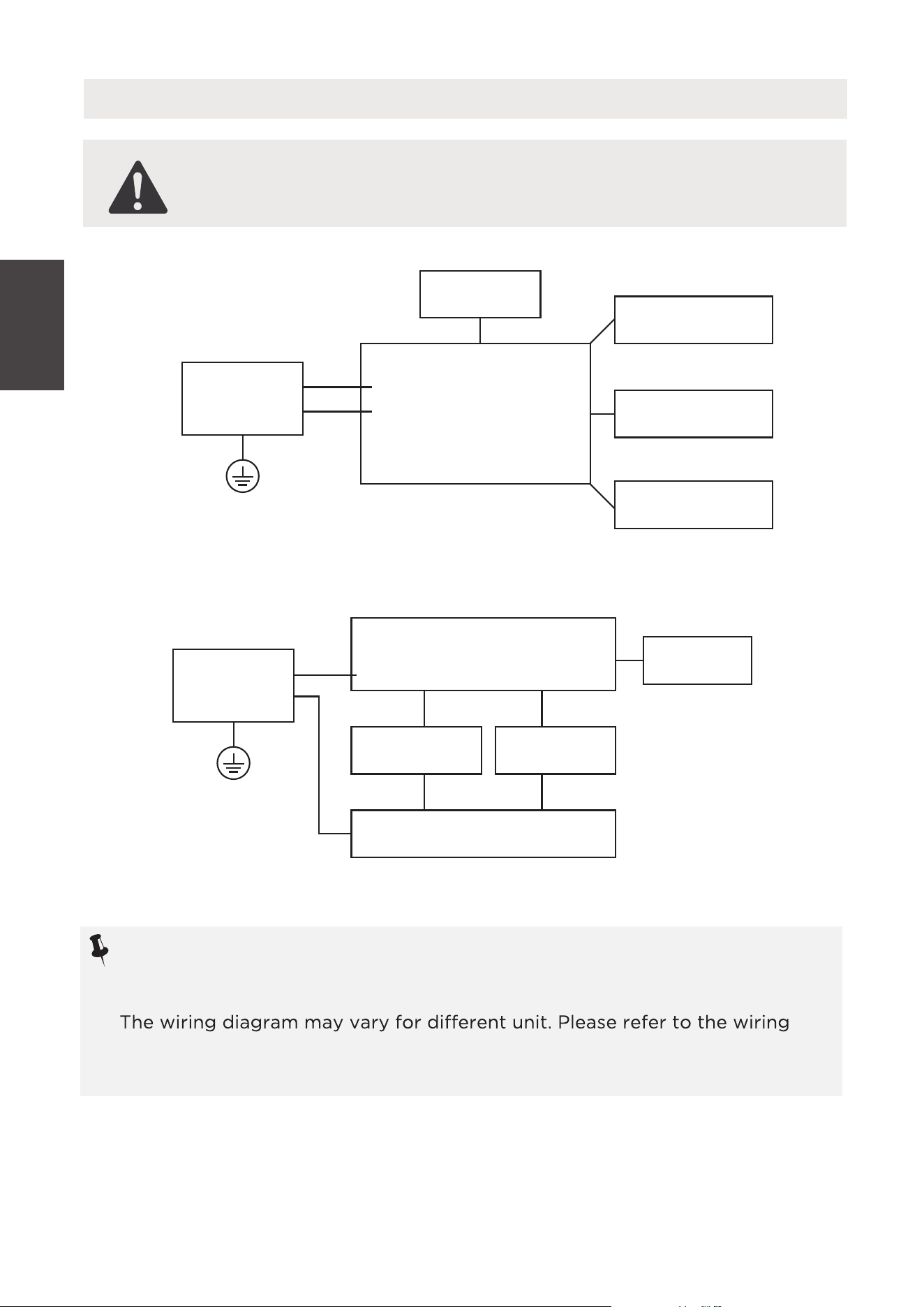
Electronic Work
WARNING:
BEFORE PERFORMING ANY ELECTRICAL OR WIRING WORK,
TURN OFF THE MAIN POWER TO THE SYSTEM.
Main Control
Compressor
Fan Motor
Display
Power
Supply
L/AC L/L1/L-IN
N/AC N/L2/N-IN
Other
MAW05R/06R Model
NOTICE:
Please strictly follow the wiring label attached to the machine for all wiring
connections.
diagram on the machine you have purchased. The above wiring diagram is a
simplified version for preliminary illustration purposes only.
Switch
Capacitor
Fan Motor
L
0
N
Power
Supply
Other
MAW05M Model
Compressor
Operating
Instructions
16
Operating
Instructions
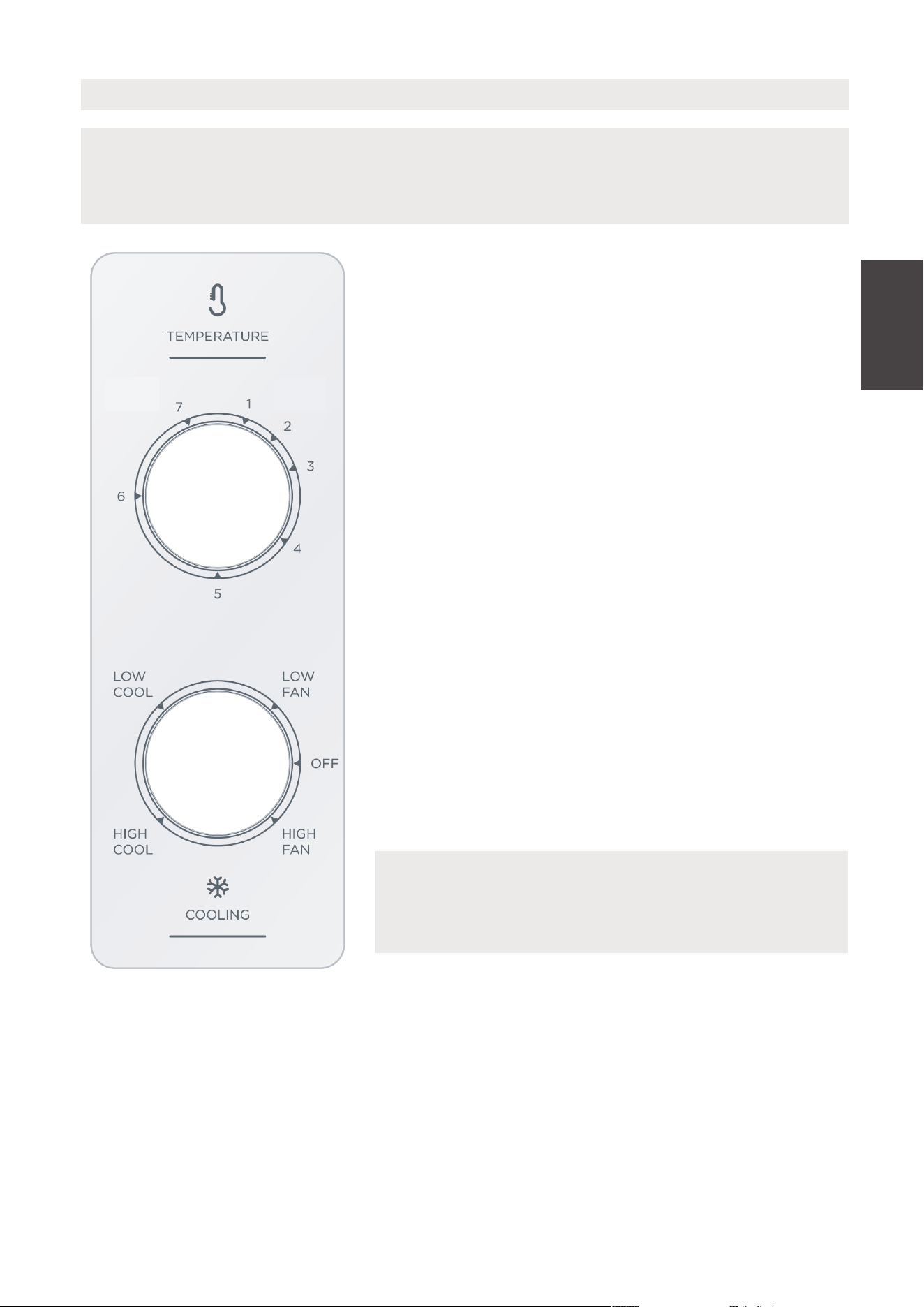
Air Conditioner Features - MAW05M Model
NOTICE
COOL MODE
The desired cool setting is selected by rotating the
knob clockwise to the desired position.
High Cool has maximum cooling eect and airflow.
Low Cool has minimum cooling eect and airflow.
FAN MODE
Rotate the knob counter clockwise to select your
choice of fan speeds for air circulation.
The controls featured in this manual are representative of many available models.
Your model’s features and appearance may vary slightly.
NOTICE
When selecting a fan speed, the compressor will
not run.
UNIT CONTROL
THERMOSTAT
The thermostat is used to set the desired room
temperature when the unit is being operated in the
COOL MODE.
To set the desired room temperature, rotate the
thermostat switch to the desired setting. After the
set temperature is achieved the thermostat will
automatically start and stop the compressor in
order to maintain the desired set temperature.
Rotate the thermostat selector clockwise for higher
cool settings. Higher cool settings will provide lower
room temperature. Rotate the thermostat selector
counter clockwise for lower cool settings. Lower
cool settings will provide higher room temperature.
MAX
COOL
MIN
COOL
17
Operating
Instructions
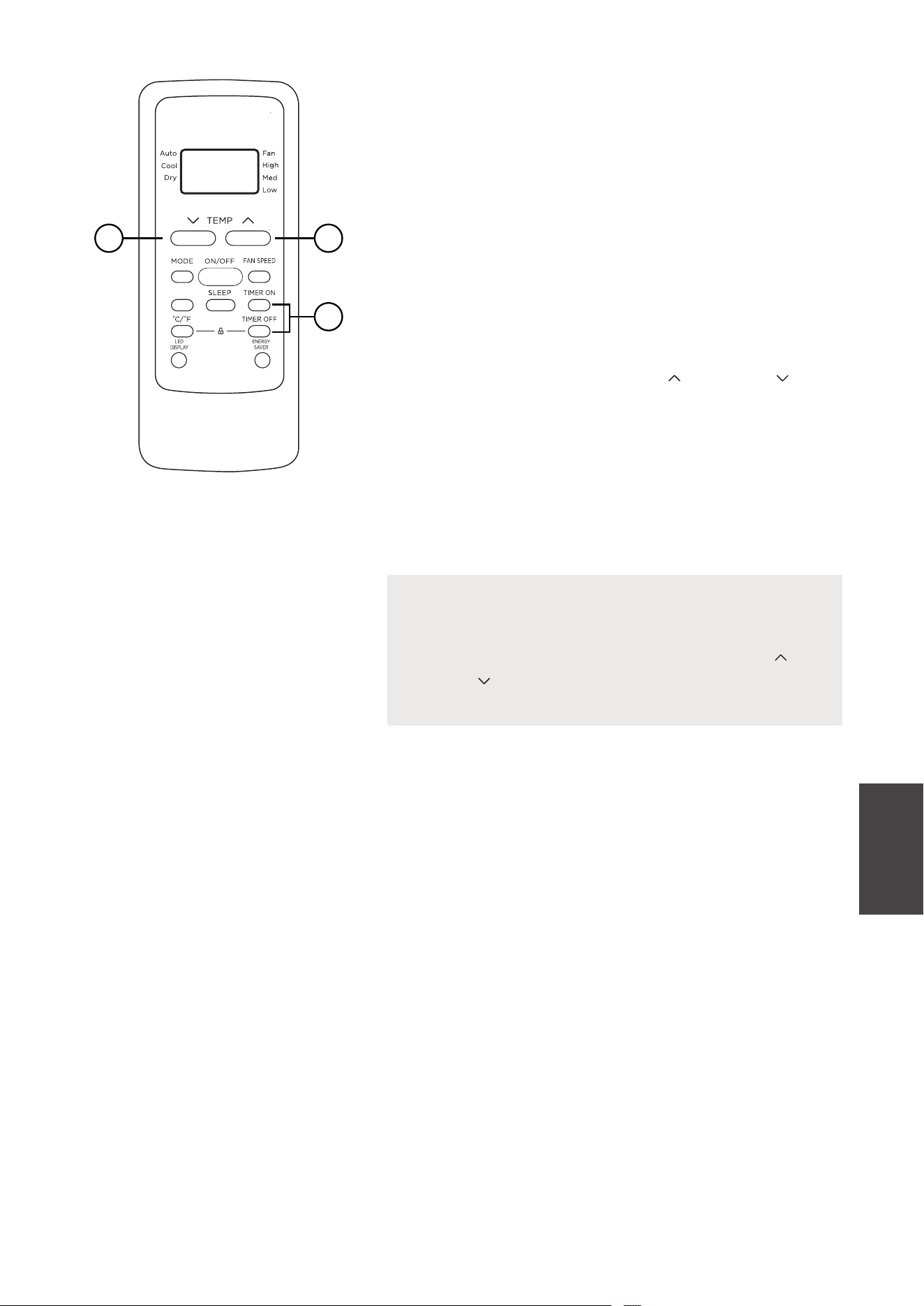
ELECTRONIC CONTROL OPERATING INSTRUCTIONS
Before you begin, thoroughly familiarize yourself with the control panel as shown
below and all its functions, then follow the symbol for the functions you desire.
The unit can be controlled by the unit control alone or with the remote controller.
TO TURN UNIT ON OR OFF:
Press ON/OFF button to turn unit
on or o.
TO CHANGE TEMPERATURE
SETTING:
Press Power button to turn unit
on or o.
NOTICE
The unit will automatically
initiate the Energy Saver
function under Cool, Dry, Auto
(only Auto-Cooling and Auto-
Fan) modes.
NOTICE
Press or hold either UP/DOWN
button until the
desired temperature is seen on
the display.
This temperature will be
automatically maintained
anywhere between 62°F (17°C)
and 86°F (30°C). If you want
to display the actual room
temperature, see To Operate on
Fan Only section.
TO ADJUST FAN SPEEDS:
Press to select the Fan Speed in
four steps-Auto, Low, Med or High.
Each time the button is pressed,
the fan speed mode is changed. On
Dry mode, the fan operates on Low
speed automatically.
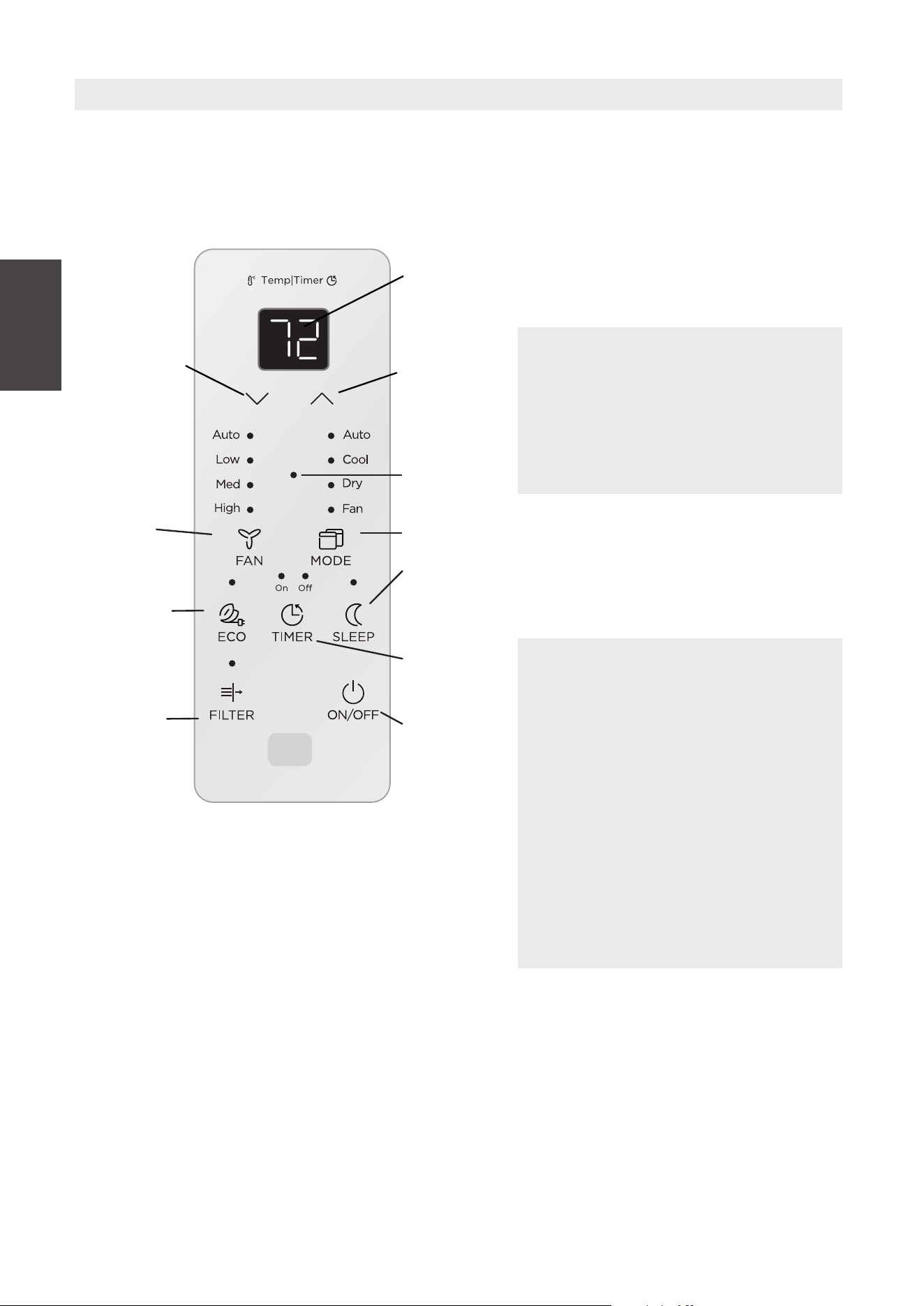
UNIT CONTROL
DISPLAYS
TEMPERATURE
OR TIME OR
ERROR CODES
ADJUSTS
TEMPERATURE
OR TIME
ADJUSTS
TEMPERATURE
OR TIME
CHECK FILTER
RESET
BUTTON
ENERGY
SAVER MODE
SLEEP MODE
SETS FAN
SPEED
SET
COMFORT
SENSE
FEATURE
S MODE
ACTIVATES
TIMER
TURNS UNIT
ON OR OFF
Air Conditioner Features - MAW05R/MAW06R Models
Comfort
Sense
18

The air conditioner will control room
temperature automatically according
to the temperature you’ve set.
In this mode, the fan speed cannot be
adjusted, as it’s automatically controlled
according to the temperature setting
and room temperature.
Operating
Instructions
SLEEP FEATURE:
Press Sleep button to initiate the
sleep mode. In this mode the selected
temperature will increase by 2°F/1
(or 2)°C 30 minutes after the mode
is selected. The temperature will then
increase by another 2°F/1 (or 2)°C after
an additional 30 minutes. This new
temperature will be maintained for 7
hours before it returns to the originally
selected temperature. The Sleep mode
program can be cancelled at any time
during operation by pressing the Sleep
button again.
CHECK FILTER FEATURE:
The Check Filter feature is a reminder
to clean the air filter for a more ecient
operation. The light will illuminate after
250 hours of operation. After cleaning
the filter, press the Filter button to reset
the Check Filter function turning the
light o.
ENERGY SAVER FEATURE:
Press Energy Saver button to
initiate this function. This function is
available on COOL, DRY, AUTO (only
AUTO-COOLING and AUTO-FAN) modes.
The fan will continue to run for 3 minutes
after the compressor shuts o. The fan
then cycles on for 2 minutes at 10 minute
intervals until the room temperature
is above the set temperature, at which
time the compressor turns back on and
Cooling resumes.
COMFORTSENSE FEATURE:
The ComfortSense function enables the
remote control to measure the
temperature at its current location. When
using AUTO, COOL, or HEAT functions,
measuring ambient temperature from the
remote control (instead of from the indoor
unit itself) will enable the air conditioner to
optimize the temperature around you and
ensure maximum comfort.
TO SELECT THE OPERATING MODE:
To choose the operating mode, press the
Mode button the unit cycles through the
modes, Auto, Cool, Dry, and Fan. The
adjacent indicator light will remain on
once the mode is selected.
The unit will automatically initiate the Energy
Saver function under Cool, Dry, Auto (only
Auto-Cooling and Auto-Fan) modes.
This feature can be activated from the
remote control ONLY.
The remote control will send this signal to
the air conditioner every 3 minutes interval
until press the ComfortSense button again.If
the unit does not receive the ComfortSense
signal during any 7 minutes interval, the unit
will beep to indicate the ComfortSense
mode has ended.
To operate on Auto mode:
•
•
•
To operate on Fan Only:
• Use this function only when cooling is not
desired, such as for room air circulation
or to exhaust stale air (on some models).
(Remember to open the vent during
this function, but keep it closed during
cooling for maximum cooling eciency.)
You can choose any fan speed you prefer.
• Durng this function, the display will
show the actual room temperature,
not the set temperature as in the
cooling mode.
• In Fan Only mode, the temperature is
not adjusted.
The fan speed is automatically controlled
based on the temperature setting and
room temperature and cannot be adjusted.
19
To operate on Dry mode:
In this mode, the air conditioner will
generally function as a dehumidifier. Since
the conditioned space is a closed or sealed
area, some degree of cooling will occur.
Displays:
Operating
Instructions
TIMER: AUTO START/STOP FEATURE:
•
•
•
•
•
•
When the unit is on or o, first press
the Timer button. The TIMER ON
indicator light illuminates indicating the
Auto Start program has initiated.
When the time of TIMER ON is
displayed, press the Timer button
again. The TIMER OFF indicator light
illuminates. It indicates the Auto Stop
program has initiated.
Press or hold the UP or DOWN
button to change the Auto time
by 0.5 hour increments, up to 10 hours,
then at 1 hour increments up to 24
hours. The control will count down the
time remaining until start.
The selected time will register in
5 seconds, and the system will
automatically revert back to display the
previous temperature setting or room
temperature when the unit is on. (when
the unit is o, there is no display.)
Turning the unit ON or OFF at any time
or adjusting the timer setting to 0.0
will cancel the Auto Start/Stop timed
program.
If setting ON 0.5 and OFF 1 at the same
time, the unit will be activated in 0.5
hour, operates for 0.5 hour and then
stops.
Displays
Shows the set temperature in “°C” or
“°F” and the Auto-timer settings. While
on Fan Only mode, it shows the room
temperature.
Error codes:
AS
- Room temperature sensor error -
Unplug the unit and plug it back in.
If error repeats, call for service.
NOTE: In Fan only mode, if the room
temperature too low or too high, it
will display “LO” or “HI”
ES - Evaporator temperature sensor error
- Unplug the unit and plug it back in. If
error repeats, call for service.
NOTICE
If the unit shuts o unexpectedly due
to the power outage, it will restart
with the previous function setting
automatically when the power resumes.
20
Operating
Instructions
Additional Information
Now that you understand the operating procedure, here are more features in your
control that you should become familiar with.
•
•
The Cool circuit has an automatic 3 minute time delayed start if the unit is turned
o and on quickly. This prevents overheating of the compressor and possible
circuit breaker tripping. The fan will continue to run during this time.
The control can display temperature in Fahrenheit or Celsius. To convert from one
to the other, press and hold the UP/DOWN Temp/Timer buttons at the same time,
for 3 seconds.
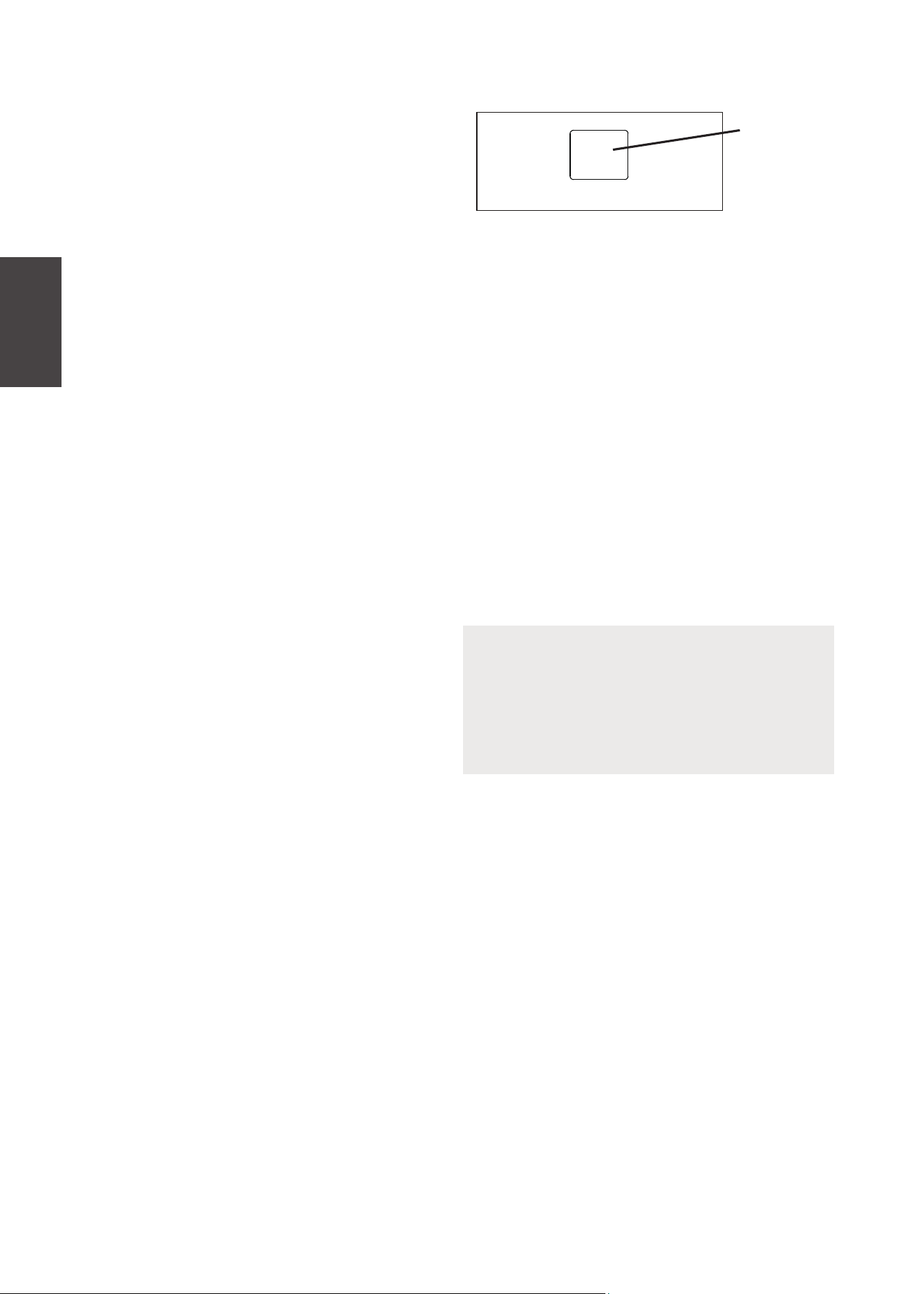
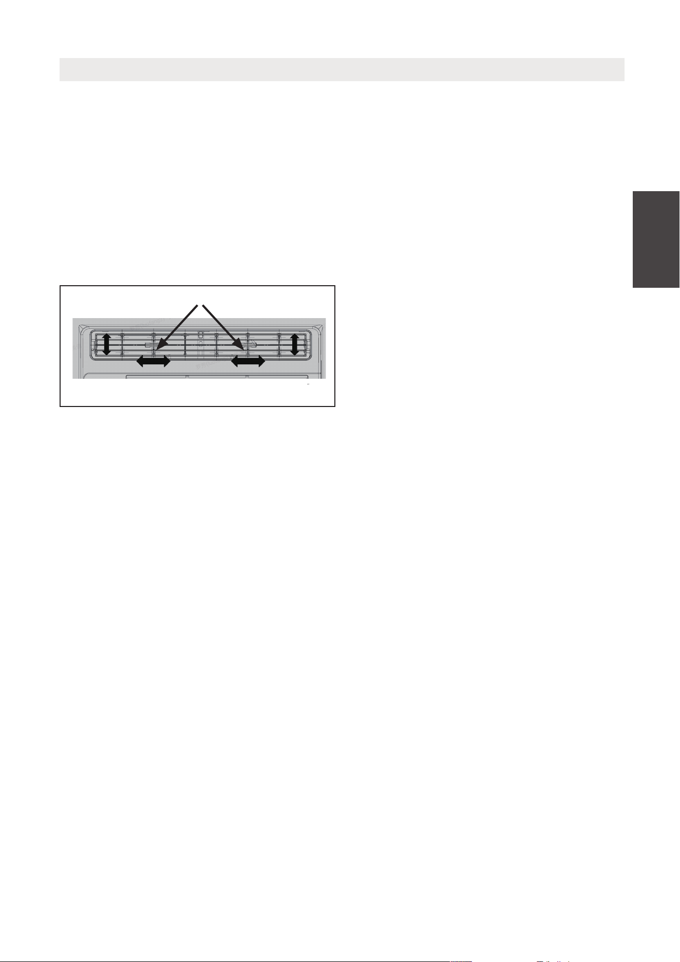
AIR DIRECTIONAL LOUVERS
The louvers will allow you to direct the air
flow Up or Down and Left or Right
throughout the room as needed.
Pivot horizontal louvers until the desired
Up/Down direction is obtained. Move the
Lever(s) from side to side until the desired
Left/Right direction is obtained.
Air Direction
Levers
21
INSTALLATION INSTRUCTIONS
Installation
Instructions
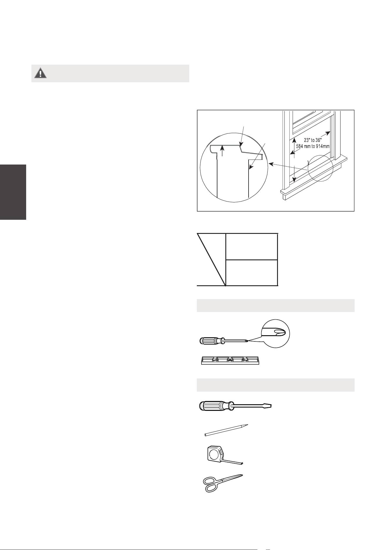
Your air conditioner is designed to install
in standard double hung windows with
opening widths of 23 to 36 inches (584mm
to 914mm)
Model
5000~6000
BTU/h
H
13”
(330mm)
H
Wooden Windows
INTERIOR
WALL
OFFSET
WINDOW
SILL
INNER
EXTERIOR
WALL
Table 1
WARNING - Before You Begin
Read these instructions completely and
carefully.
• IMPORTANT - Save these
instructions for local inspector’s use.
• IMPORTANT - Observe all governing
codes and ordinances.
• Note to Installer - Be sure to
leave these instructions with the
consumer.
• Note to Consumer - Keep these
instructions for future reference.
• Skill level - Installation of
this appliance requires basic
mechanical skills.
• Completion time - Approximately
1 hour. We recommend that two
people install this product.
Proper installation is the responsibility
of the installer.
Product failure due to improper
installation is not covered under the
Warranty.
You MUST use all supplied parts and
use proper installation procedures as
described in these instructions when
installing this air conditioner.
Do not, under any circumstances, cut or
remove the third (ground) prong from
the power cord.
Do not change the plug on the power
cord of the air conditioner.
Aluminum house wiring may present
special problems - consult a qualified
electrician.
When handling the unit, be careful to
avoid cuts from sharp metal edges
and aluminum on front and rear coils.
Tools You Will Need
Phillips
Screwdriver
Level
Tools You May Use
Flathead
Screwdriver
Pencil
Ruler or tape measure
Scissors or knife
22
CAUTION
When handling unit, be careful to
avoid cuts from sharp metal edges
and aluminum fins on front and rear
coils.
1. PREPARE THE WINDOW
Lower sash must open suciently to allow a clear vertical opening (see dimension
H in Table 1). Side louvers and the rear of the AC must have clear air space to allow
enough airflow through the condenser for heat removal. The rear of the unit must be
outdoors, not inside a building or garage.
NOTICE
Save the carton and these installation instructions for future reference. The carton
is the best way to store the unit when not in use.
Installation
Instructions
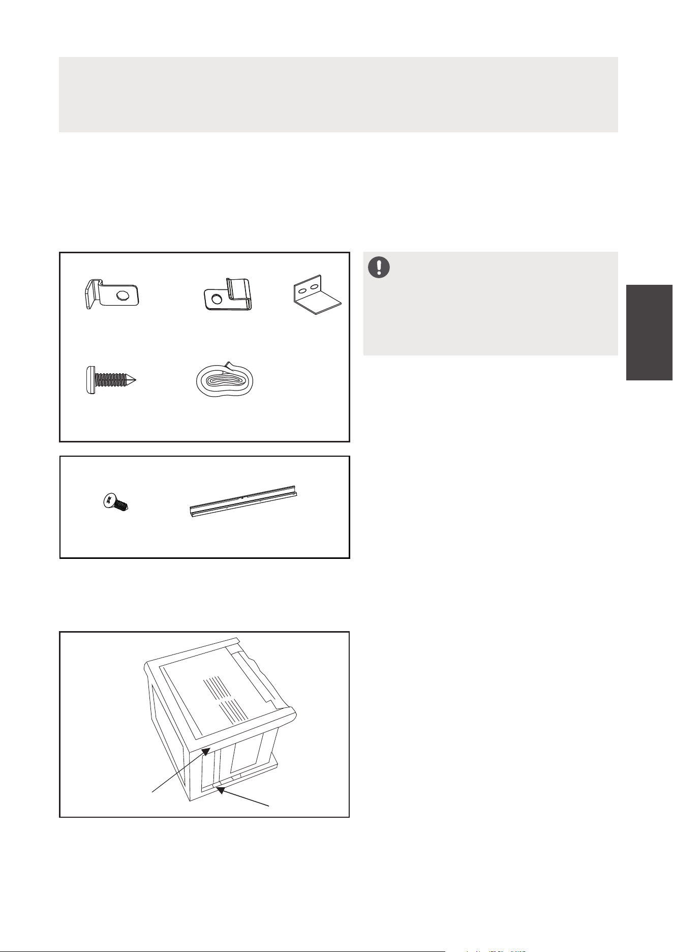
Mounting Hardware
3/4’’ (or 1/2”)
Screws
(7)
Lock Frame
(For Wooden windows)
(2)
Sash Lock
(1)
Window sash
seal foam
(1)
Lock Frame
(For Vinyl-Clad windows)
(2)
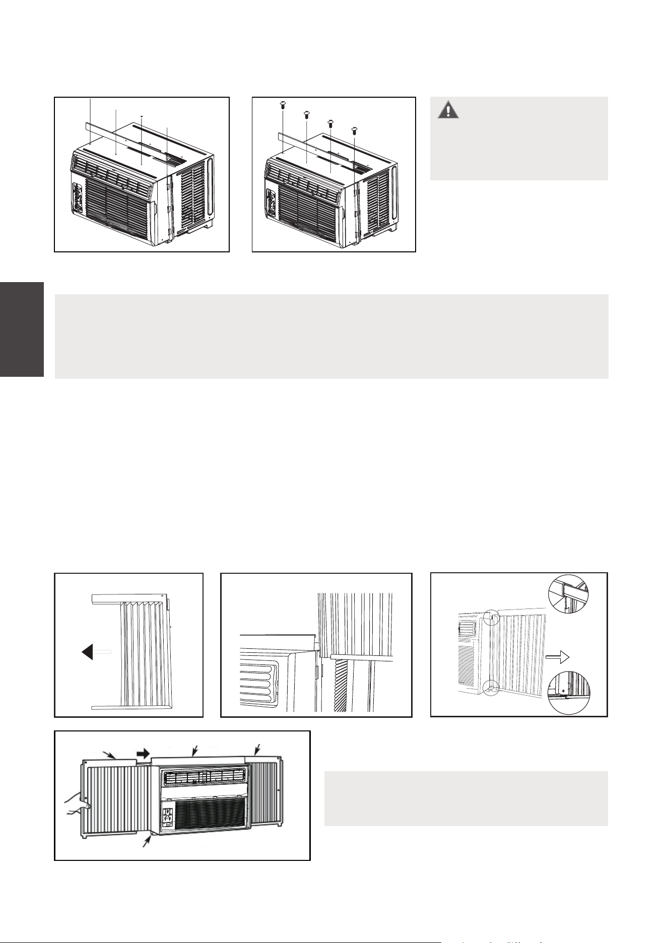
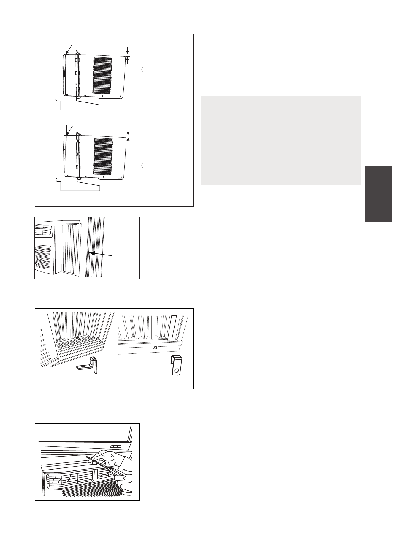
2. PREPARE THE AIR CONDITIONER
Before installing the unit, the top rail must be assembled on the unit.
A: Remove the air conditioner from the
carton and place on a flat surface.
B: Remove top rail from the packaging
material as shown in Fig. A.
Packaging
Top Rail
Fig. A
3/8” Screws
(4)
Top Rail
(1)
Top Rail Hardware
23
Installation
Instructions
1. Place unit on the floor, a bench or a table. There is a left and right side accordion
panel; be sure to use the proper panel for each side. When installed, the flange for
securing the panel in place to the window sill will be facing into the room.
A. Hold the side panel in one hand and gently pull back the center to free the open
end. See Fig. 1.
B. Slide the free and “ ” section of the panel directly into the cabinet as shown in Fig. 2.
I
Slide the panel down. Be sure to leave enough space to slip the top and bottom of
the frame into the rails on the cabinet.
C. Once the panel has been installed on the side of the cabinet, make sure it sits
securely inside the frame channel by making slight adjustments. Slide the top and
bottom ends of the frame into the top and bottom rails of the cabinet. Fig. 3.
NOTICE
The Top rail and Sliding Panels on each side are oset to provide the proper pitch
to the rear of 5/16” (8mm). This is necessary for proper condensate management
and drainage. If you are not using the side panels for any reason, this pitch to the
rear must be maintained.
For safety reasons, all
four (4) screws MUST be
securely fastened.
C: Align the hole in the top rail with those in the top of the unit as shown in Fig. B.
D: Secure the top rail to the unit with the 3/8” (9.5mm) screws as shown in Fig. C.
3. INSTALL THE ACCORDION PANELS
Fig.B
Fig. B
Fig.C
Fig. C
NOTICE
If storm window blocks AC, see Fig. 11.
Top Rail
Bottom Rail
Top left
Top right
Fig. 4
D. Slide the panel all the way in and repeat
on the other side.
Fig. 1
Top Rail
Bottom Rail
Fig. 3
“I” section
Fig. 2
“I” section
WARNING
24
Installation
Instructions
2. While keeping a firm grip on the air
conditioner, carefully place the unit into
the window opening so the bottom of
the air conditioner frame is against the
window sill (Fig. 5). Carefully close the
window behind the top rail of the unit.
NOTICE
Check that air conditioner is tilted back
per dimension H (Fig. 5) (tilted about 3°
to 4° downward to the outside). After
proper installation, condensate should
not drain from the overflow drain hole
during normal use. Adjust the slope if
otherwise.
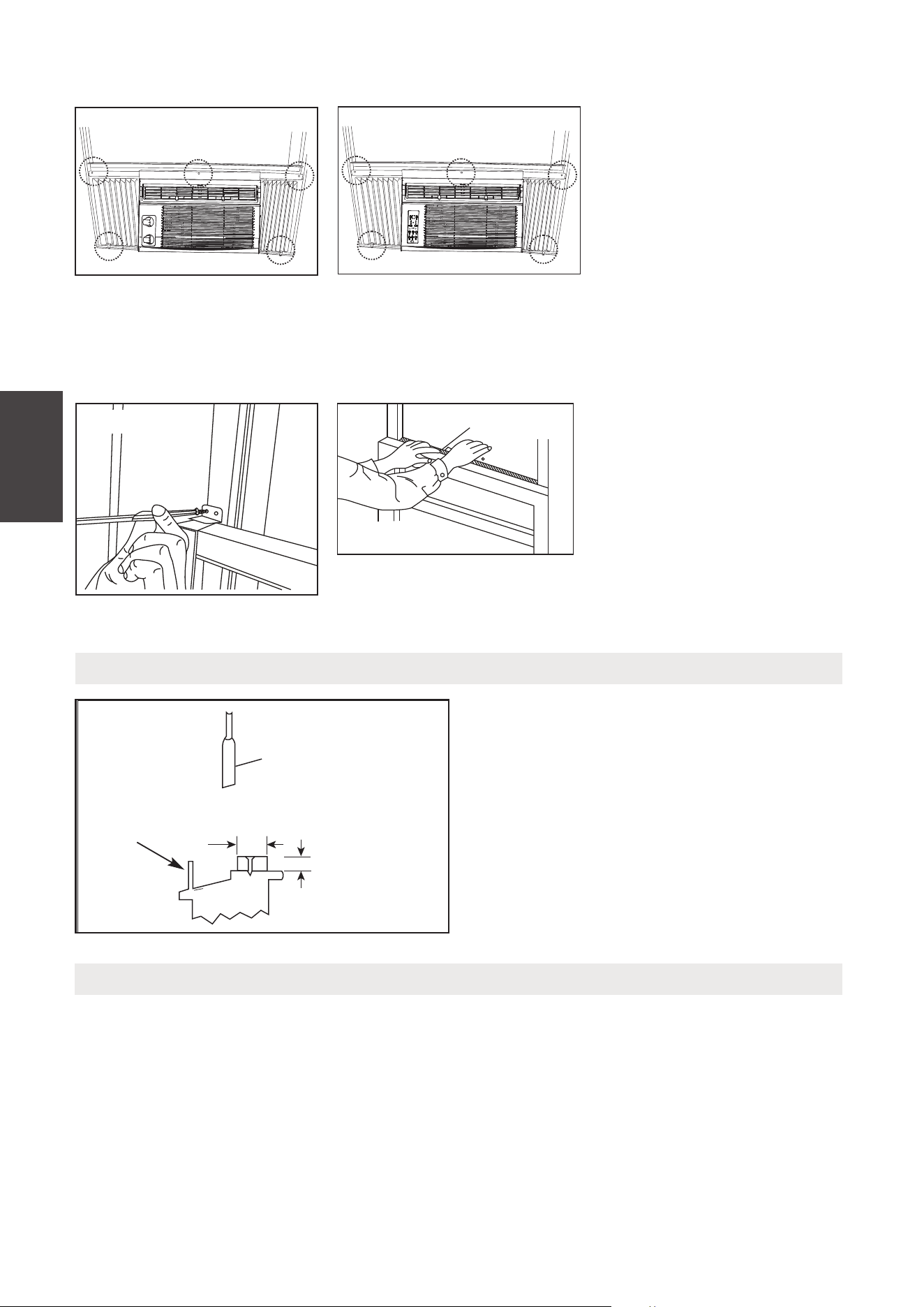
3. Extend the side panels out against the window
frame (Fig. 6).
window
frame
Fig. 6
Fig. 5
Wooden Windows
INSIDE
OUTSIDE
Measure from the cabinet edge
H
H:About
3/4” to 1 ”
Vinyl-Clad Windows
INSIDE
OUTSIDE
H:About 3/4” to 1”
for 5K to K)
Measure from the cabinet edge
H
Fig. 7A Fig. 7B
Fig. 8A
5. SECURE AIR CONDITIONER
4. INSTALL AIR CONDITIONER
A. Place the frame lock between the
frame extensions and the window
sill as shown (Fig. 7A for Wooden
windows), (Fig. 7B for Vinyl-Clad
windows).
Drive 3/4” (19 mm) or 1/2” (12.7 mm)
locking screws through the frame lock
and into the sill.
NOTE: To prevent window sill from
splitting, drill 1/8” (3 mm) pilot holes
before driving screws.
B1: For wooden windows:
Drive 1/2” (12.7 mm) locking screws through the
frame lock and into the sill (Fig. 8A).
NOTE: To prevent window sill from splitting, drill 1/8”
(3mm) pilot holes before driving screws. Drive 1/2”
(12.7mm) locking screws through frame holes into
window sash (Fig. 8B/8C).
6
for 5K to K)
6
25
Installation
Instructions
Fig. 9
FOAM SEAL
Fig. 10
If AC is Blocked by Storm Window
Add wood as shown in Fig. 11, or remove
storm window before air conditioner is
installed.
If storm window frame must remain,
be sure the drain holes or slots are not
caulked or painted shut. Accumulated
rain water or condensation must be
allowed to drain out.
Fig. 11
SASH
1-1/2"min
(38 mm)
Board thickness
as required, for
proper pitch to rear,
along entire
sill. Fasten with nails
or screws.
Storm window
frame or other
obstruction.
Removing AC From Window
•
•
•
•
•
•
MAW05R/MAW06R Models
Fig. 8C
MAW05M Model
Fig. 8B
B2: For Vinyl-Clad windows:
Drive 1/2” (12.7 mm)
locking screws through
the top rail and into
the window sash (Fig.
8B/8C
).
NOTE: Before driving
the screws, drill 5 holes
into the window through
the holes of the top rail
and side panel frames
as shown (Fig. 8B/8C).
C. Secure lower sash in
place by attaching the
sash lock with the 3/4”
(19 mm) or 1/2” (12.7 mm)
screw as shown (Fig. 9).
D. Cut Window sash seal
foam and insert it in
the space between the
upper and lower sashes
(Fig. 10).
Turn AC o, and disconnect power cord.
Remove sash seal from between windows, and unscrew sash lock.
Remove screws installed through top rail and side panel frames.
Close (slide) the side panels into the rails.
Keeping a firm grip on the air conditioner, raise the sash and carefully remove.
Be careful not to spill any condensate while lifting unit form window. Store parts
WITH air conditioner.
26
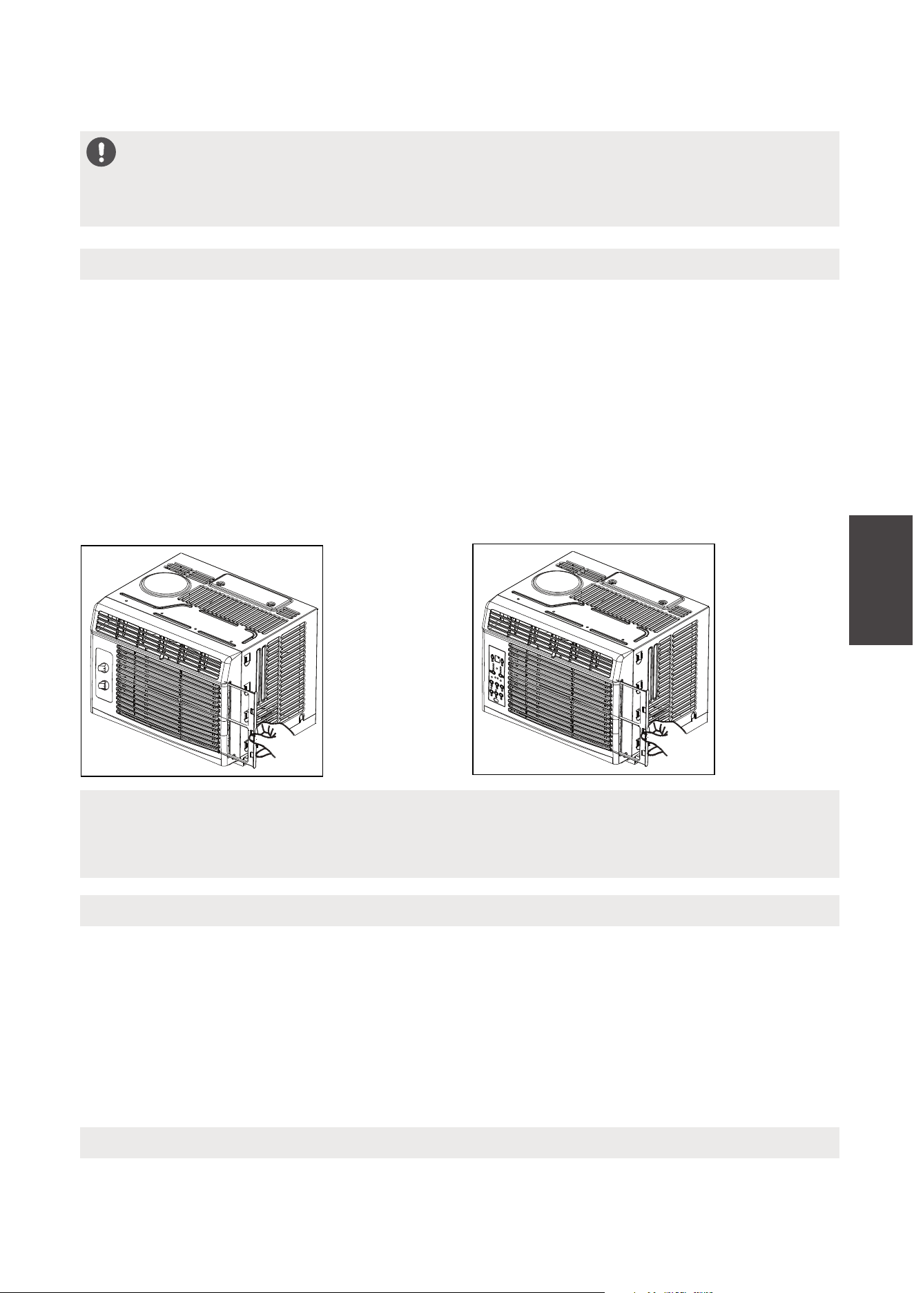
CARE AND CLEANING
Air Filter Cleaning
Cabinet Cleaning
Winter Storage
• Be sure to unplug the air conditioner to prevent shock or fire hazard. The cabinet and
front may be dusted with an oil-free cloth or washed with a cloth dampened in a
solution of warm water and mild liquid dishwashing detergent. Rinse thoroughly and
wipe dry.
• Never use harsh cleansers, wax or polish on the cabinet front.
• Be sure to wring excess water from the cloth before wiping around the controls.
Excess water in or around the controls may cause damage to the air conditioner.
• Plug in air conditioner.
Care and
Cleaning
CAUTION
Clean your air conditioner occasionally to keep it looking new. Be sure to unplug
the unit before cleaning to prevent shock or fire hazards.
NOTICE
Never use hot water over 104°F (40°C) to clean the air filter. Never attempt to
operate the unit without the air filter.
If you plan to store the air conditioner during the winter, remove it carefully from the
window according to the installation instructions. Cover it with plastic or return it to
the original carton.
The air filter should be checked at least once a month to see if cleaning is necessary.
Trapped particles in the filter can build up and cause an accumulation of frost on the
cooling coils.
• Push the vent handle to the closed position (where applicable). Open the front panel.
• Take the filter by the center and pull up and out.
• Wash the filter using liquid dishwashing detergent and warm water. Rinse filter
thoroughly.
• Gently shake excess water from the filter. Be sure the filter is thoroughly dry
before replacing.
• You may also vacuum the filter clean rather than washing.
MAW05R/MAW06R Models
MAW05M Model
27
Troubleshooting
Tips
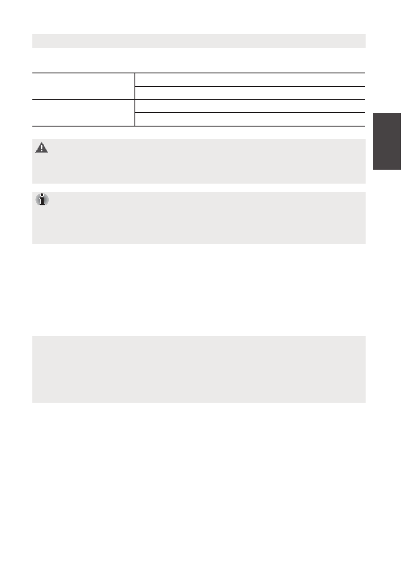
Before calling for service, review this list. It may save you time and expense. This list
includes common occurrences that are not the result of defective workmanship or
materials in this appliance.
Problem Solution
Air conditioner
does not start.
Circuit breaker tripped. Reset circuit breaker.
Check if the light on the plug is on. If it is o , press the RESET button.
Power is OFF. Turn power ON.
Unit turned o and then on quickly. Turn unit o and wait 3 minutes
before restarting.
Air from unit
does not feel
cold enough.
Room temperature below 62°F (17°C). Cooling may not occur until
room temperature rises above 62°F (17°C).
Temperature sensor behind the air fi lter is touching the cold coil. Try
to move it so it does not contact the cold coil.
Reset to a lower temperature.
Compressor shut-o by changing modes. Wait approximately 3 minutes
and listen for compressor to restart when set in the COOL mode.
Check for potential obstructions blocking the outdoor intake/exhaust.
Clear any obstructions.
Air conditioner
cooling, but
room is too
warm- ice forming
on cooling coil
behind air filter.
Outdoor temperature below 64°F (18°C). To defrost the coil, set to
FAN ONLY mode.
Air fi lter may be dirty. Clean fi lter. Refer to Care and Cleaning section.
To defrost, set to FAN ONLY mode.
Thermostat set too cold for night-time cooling. To defrost the coil, set
to FAN ONLY mode. Then, set temperature to a higher setting.
Air conditioner
cooling, but room
is too warm- NO
ice forming on
cooling coil
behind air filter.
Dirty or restricted air fi lter. Clean fi lter. Refer to Care and Cleaning
section. To defrost, set to FAN ONLY mode.
Temperature is set too high, set temperature to a lower setting.
Air directional louvers positioned improperly. Position louvers for
better air distribution.
Front of unit is blocked by drapes, blinds, furniture, etc. - restricts air
distribution. Clear obstruction in front of unit.
Any open doors, windows, or registers may allow cold air to escape.
Close any doors, windows, or registers.
The room may be too warm. Allow additional time to remove “stored
heat” from walls, ceiling, fl oor and furniture.
TROUBLESHOOTING TIPS
Wall plug disconnected. Push plug firmly into wall outlet.
28
Troubleshooting
Tips
Problem Solution
Air conditioner
turns on and o
rapidly.
Dirty air filter - air restricted. Clean air filter.
Outside temperature extremely hot. Set FAN speed to a higher setting
to bring air past cooling coils more frequently.
Check for potential obstructions blocking the outdoor intake/exhaust.
Clear any obstructions.
Noise when unit
is cooling.
Air movement sound. This is normal. If too loud, set to a slower FAN
setting.
Window vibration - poor installation. Refer to installation instructions
or check with installer.
Water dripping
INSIDE when unit
is cooling.
Improper installation. Tilt air conditioner slightly to the outside to
allow water drainage.
Refer to installation instructions - check with installer.
Water dripping
OUTSIDE when
unit is cooling.
Unit removing large quantity of moisture from humid room. This is
normal during excessively humid days.
Remote sensing
deactivating
prematurely
(some models).
Remote control not located within range. Place remote control within
26.2 feet & 180°, radius of the front of the unit, and pointed
in the general direction of the air conditioner unit.
Remote control signal obstructed. Remove obstruction.
Room too cold.
Noise when unit
starts.
A “da-da” sound may occur for thirty seconds when the unit is turned
on due to the compressor starting. It is normal.
Temperature setting too low. Increase temperature setting.
29
REMOTE CONTROL INSTRUCTIONS
Operating
Instructions
(With Remote)
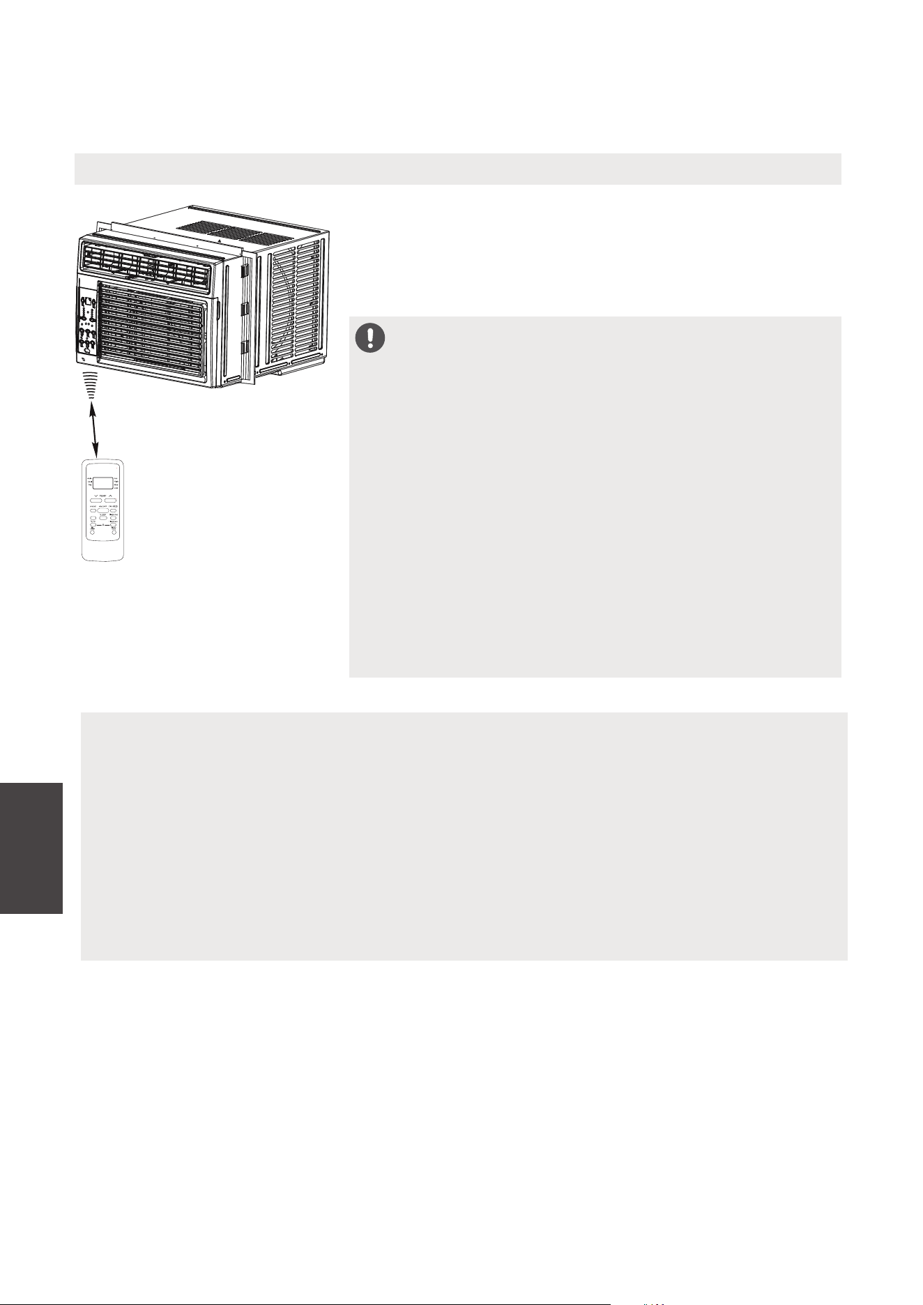
LOCATION OF THE REMOTE CONTROLLER
Use the remote controller within a distance of 26.2 ft
(8 meters) from the air conditioner, pointing it towards
the receiver. Reception is confirmed by a beep.
26.2 ft (8 meters)
Handling the Remote Controller
CAUTION
• The air conditioner will not operate if curtains,
doors or other materials block the signals from the
remote controller to the unit.
• Prevent any liquid from spilling onto the remote
controller. Do not expose the remote controller to
direct sunlight or heat.
• If the infrared signal receiver on the indoor unit is
exposed to direct sunlight, the air conditioner may
not function properly. Use curtains to prevent the
sunlight from falling on the receiver.
• If other electrical appliances react to the remote
controller, either move these appliances or consult
your local dealer.
NOTES
• Button design is based on typical model and may vary slightly from the actual
one you purchased.
• All the functions described are accomplished by the unit. If the unit is without
a feature, the unit will not respond if the corresponding button on the remote
is pressed.
• When there are significant dierences between features or operation implied
by the remote control illustration and the actual functions described in the
USER’S MANUAL, the descriptions in the USER’S MANUAL shall prevail.
C-SENSE
30
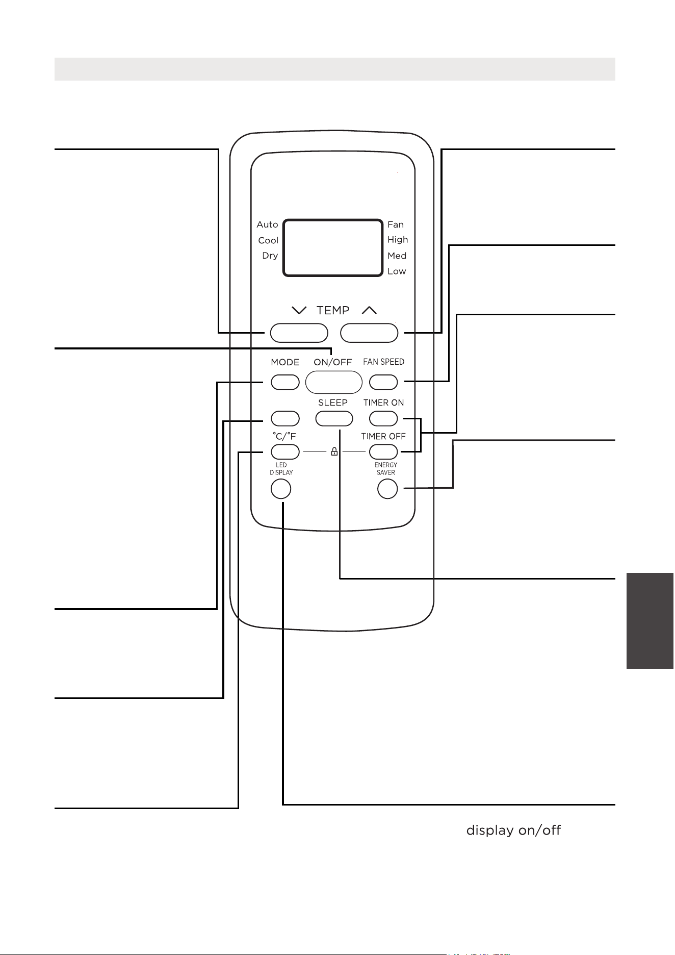
Function Buttons
MODE Button
Press this button to
select the desired
operation mode.
TEMP UP Button
Press this button to
increase the indoor
temperature setting.
SPEED Button
Used to select the
desired fan speed.
SLEEP Button
Press this button to
LED DISPLAY Button
Turns the unit’s LED
activate the Sleep
mode. This function
is available on COOL
or AUTO mode only
and will maintain the
most comfortable
temperature for you
while saving energy.
For more details, see
“sleep operation” in
Page 14
ENERGY SAVER Button
Press this button to
activate the Energy
saving mode. Press
it again to stop the
function
TEMP DOWN Button
Press this button to
decrease the indoor
temperature setting.
TIMER Button
Press this button to
activate the “Auto
Start” or “Auto Stop”
program.
ON/OFF Button
Operation starts when
this button is pressed
and stops when the
button is pressed again.
Press this button to active
the ComfortSense mode, to
optimize the temperature
around you and ensure
maximum comfort.
°C/°F Button
Press this button to change
the temperature display
between Celsius and Fahrenheit.
Operating
Instructions
(With Remote)
C-SENSE
COMFORTSENSE Button
NOTE: If the unit
has ENERGY SAVER
function, it will initiate
automatically the
Energy Saver function
under Cool, Dry, and
Auto (only Auto-
Cooling and Auto-Fan)
modes.
31
Operating
Instructions
(With Remote)
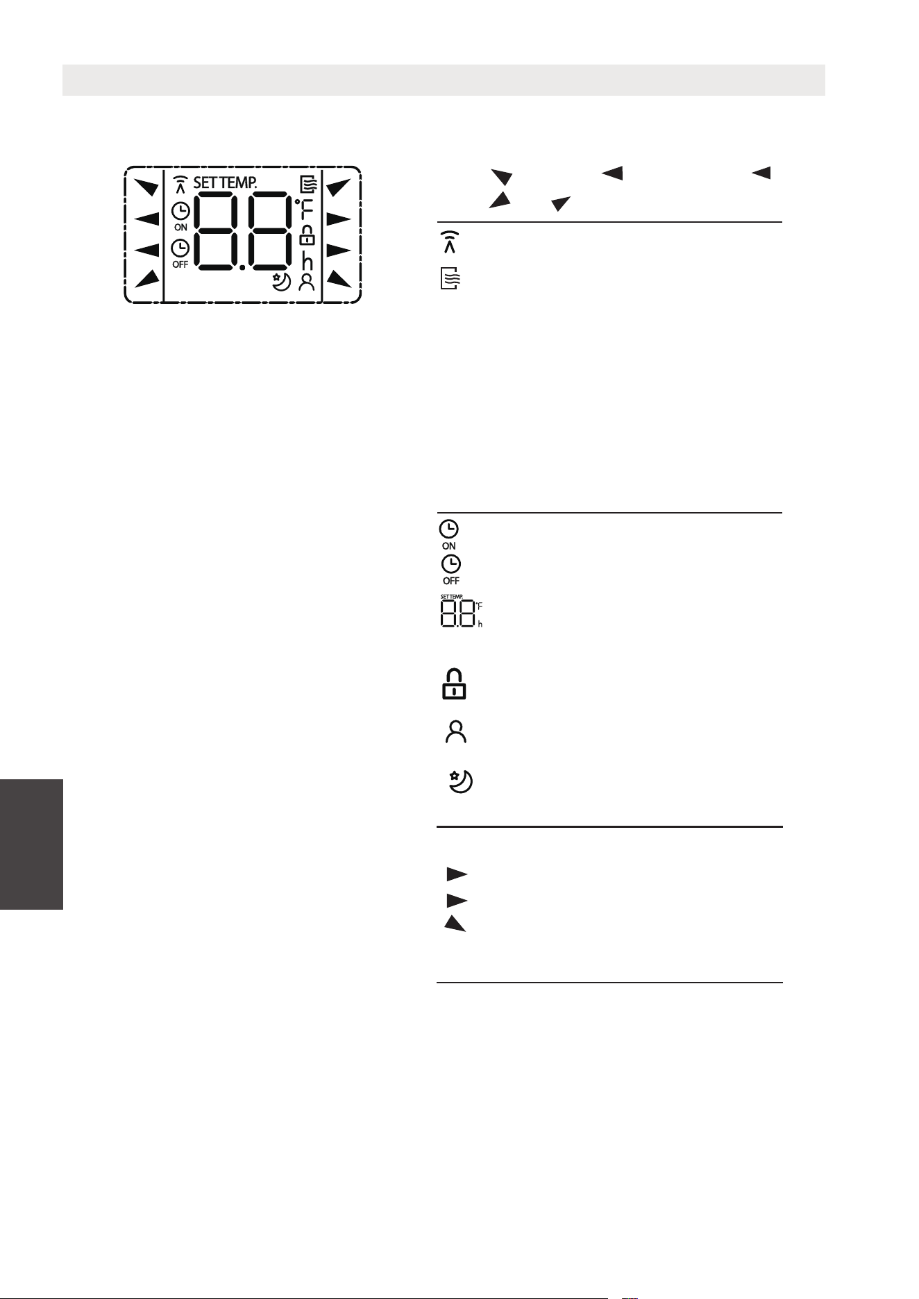
Information are displayed when the remote controller is power up.
All indicators shown in the figure are for the purpose of clear presentation.
But during the actaul operation, only the relative function signs are shown
on the display window.
Remote Screen Indicators
Displayed when data transmitted.
Appears when the remote is enabled
and can send a signal to the unit. If
you would like to turn the remote o
without aecting the unit, point the
remote away from the unit and press
the ON/OFF button.
To turn the remote on, point the
remote away from the unit and press
the ON/OFF button. The unit will not
receive commands from the remote
if this indicator is not illuminated.
AUTO
COOL
DRY
HEAT
AUTO
HEAT
COOL
FAN
DRY
Mode display
FAN
HIGH
MED
LOW
Low speed
NO display
Medium speed
High speed
Auto fan speed
Displayed when TIMER ON time is set
Displayed when TIMER OFF time is set
Indicated all the current settings are
locked
Shows set temperature or room
temperature, or time under TIMER
setting
HIGH
MED
LOW
Fan speed indication
Displayed when ComfortSense feature
is activated(some units)
Displayed when SLEEP feature is
activated
Note:
32
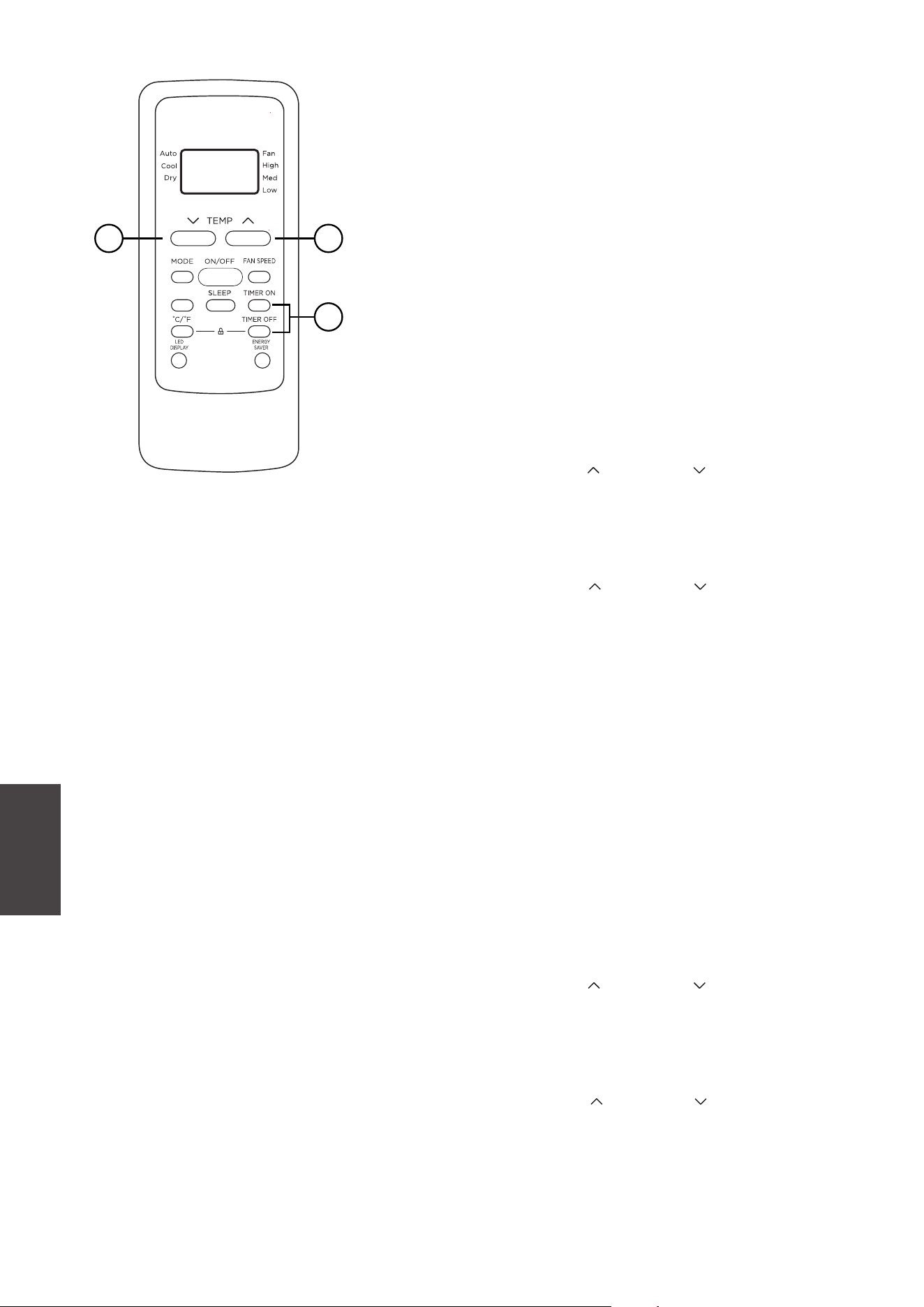
TIMER OPERATION
Press the TIMER button to initiate the Auto-start
and Auto-stop setting program of the unit.
To set the Auto-start/stop time.
1. Press the TIMER button, when the TIMER ON
indicator is displayed on the LED window of
the air conditioner, it indicates the Auto Start
setting program is initiated. When the TIMER
OFF indicator is displayed on the LED window
of the air conditioner, it indicates the Auto
Stop setting program is initiated.
2. Press or hold the TEMP UP ( )/DOWN ( ) to
change the Auto time. The control will count
down the time remaining until start/stop.
3. The selected time will register in 5 seconds and
the air conditioner will automatically revert back
to display the previous temperature setting.
4. Turning the unit ON or OFF at any time will
cancel the Auto Start/stop function.
NOTES
To cancel the TIMER setting, push the TIMER
button and press or hold the TEMP UP ( )/
DOWN ( ) until 0 hour is displayed on the LCD
window of the air conditioner.
1
22
Operating
Instructions
(With Remote)
C-SENSE
33
COMBINED TIMER
(Setting both ON and OFF timers simultaneously)
AUTO STOP >AUTO START
(On > Stop > Start operation)
This feature is useful when you want to stop the
air conditioner after you go to bed, and start it
again in the morning when you wake up or when
you return home.
Example:
To stop the air conditioner 2 hours after setting
and start it again 10 hours after setting.
AUTO START > AUTO STOP
(Off > Start > Stop operation)
This feature is useful when you want to start the
air conditioner before you wake up and stop it
after you leave the house.
Example:
To start the air conditioner 5 hours after setting,
and stop it 8 hours after setting.
1
22
Operating
Instructions
(With Remote)
C-SENSE
1. Press the TIMER button until the TIMER OFF
indicator is displayed on the LED display of
the air conditioner.
2. Use the TEMP UP ( )/DOWN ( ) button to
display “2.0” on the LED display of the air
conditioner.
3. Press the TIMER button again to display the
TIMER OFF on the LED display of the unit.
4. Use the TEMP UP ( )/DOWN ( ) button to
display “10” on the LED display of the unit.
5. Wait for 5 seconds until the previous display
appears in LED window.
1. Press the TIMER button until the TIMER ON
indicator is displayed on the LED display of
the air conditioner.
2. Use the TEMP UP ( )/DOWN ( ) button to
display “5.0” on the LED display of the air
conditioner.
3. Press the TIMER button again to display the
TIMER OFF on the LED display of the unit.
4. Use the TEMP UP ( )/DOWN ( ) button to
display “8.0” on the LED display of the unit.
5. Wait for 5 seconds until the previous display
appears in LED window.
34

and Battery
Warning
NOTES
• Button design is based on a typical model and may slightly vary from the actual
one you purchased.
• This device complies with part 15 of the FCC Rules. Operation is subject to the
following two conditions: (1) This device may not cause harmful interference,
and (2) this device must accept any interference received, including interference
that may cause undesired operation.
•
This equipment has been tested and found to comply with the limits for a Class
B digital device, pursuant to part 15 of the FCC Rules. These limits are designed
to provide reasonable protection against harmful interference in a residential
installation. This equipment generates, uses and can radiate radio frequency
energy and, if not installed and used in accordance with the instructions, may cause
harmful interference to radio communications. However, there is no guarantee that
interference will not occur in a particular installation. If this equipment does cause
harmful interference to radio or television reception, which can be determined by
turning the equipment o and on, the user is encouraged to try to correct the
interference by one or more of the following measures:
- Reorient or relocate the receiving antenna.
- Increase the separation between the equipment and receiver.
- Connect the equipment to an outlet on a circuit dierent from that to which the
receiver is connected.
- Consult the dealer or an experienced radio/TV technician for help.
- Changes or modifications not approved by the party responsible for compliance
could void users authority to operate the equipment.
Battery Warning:
Do not mix old and new batteries and Do not mix alkaline, standard (carbon-zinc)
or rechargeable (ni-cad, ni-mh, etc.) batteries
Unique Identifier: Midea brand,RG51G(1)/CEFU1-1,RG51G(1)/CEFU1
Responsible Party U.S. Contact Information
Midea America Corporation
300 Kimball Dr
Parsippany NJ
07054
This device complies with Part 15 of the FCC Rules. Operation is subject to the
following two conditions: (1) This device may not cause harmful interference, and
(2) this device must accept any interference received, including interference that
may cause undesired operation.
Telephone number or internet contact information: Midea.com/us
FCC Compliance Statement ( products subject to Part 15)
Supplier's Declaration of Conformity
47 CFR § 2.1077 Compliance Information
35
Operating
Instructions
(With Remote)
WARRANTY
Air Conditioner Limited Warranty
Your product is protected by this Limited Warranty:
Warranty service must be obtained from Midea Consumer Services or an authorized Midea servicer.
Warranty
Midea, through its authorized servicers will:
• Pay all costs for reparing or replacing parts of this appliance which prove to be defective in materials or workmanship.
Consumer will be responsible for:
• Diagnostics, removal, transportation and reinstallation cost required because of service.
• Costs of service calls that are a result of items listed under NORMAL RESPONSABILITIES OF THE CONSUMER**
Midea replacement parts shall be used and will be warranted only for the original warranty.
NORMAL RESPONSABILITIES OF THE CONSUMER**
This warranty applies only to products in ordinary household use, and the consumer is responsible for the items
listed below:
1. Proper use of the appliance in acordance with instructions provided with the product.
2. Routine maintenance and cleaning necessary to keep the good working condition.
3. Proper installation by an authorized service professional in accordance with instructions provided with the
appliance and in accordance with all local plumbing, electrical and/or gas codes.
connections or defects in house wiring.
5. Expenses for making the appliance accessible for servicing.
6. Damages to finish after intallation.
EXCLUSIONS
This warranty does not cov
er the following:
1) Failure caused by damage to the unit while in your possesion (other than damage caused by defect or
malfunction), by its improper installation, or by unreasonable use of the unit, including without limitation, failure to
provide reasonable and necessary maintenance or to follow the written installation and Operating Instructions.
2) Damages caused by services performed by persons other than authorized Midea costumer service; or external
causes such as abuse, misuse, inadequate power supply or acts of God.
3) If the unit is put to commercial, business, rental, or other use or application other than for consumer use, we make
no warranties, express or implied, including but not limited to, any implied warranty of merchantability or fitness
for use or purpose.
4) Products without original serial numbers or products that have serial numbers which have been altered or cannot
be readily determined.
NOTE: Some states do not allow the exclusions or limitation of incidental or consequential damages. So this
limitation or exclusion may not apply to you.
IF YOU NEED SERVICE
Keep your bill of sale, delivery slip, or some other appropriate payment Record.
The date on the bill establishes the warranty period, should service be required.
If service is performed, its your best interest to obtain and keep all rec
eipts.
This written warranty gives you specific legal rights. You may also have other rights that vary from state to state.
Service under this warranty must be obtained by following these steps, in order:
1) Contact Midea Consumer Services or an authorized Midea services at 1 866 646 4332.
2) If there is a question as to where to obtain service, contact our consumer relations Departament.
ty
Warranty
•
•
36
One year full warranty from the date of delivery or the purchase date, whichever is later.
The date of delivery establishes the warranty period, should service be required.
Questions about installing or operating your
Midea product?
If you still need assistance, please call Customer
Service at 1-866-646-4332.
Have your sales receipt, serial number and product model
mumber available when you call.
The product may be returned within 30 days of purchase
with receipt, After 30 days, the product is covered under
limited warranty. Please refer to the warranty section
in the User Manual for details.
Return policy
save your
receipt
RETURN POLICY
30
37
MANUAL DEL USUARIO
NÚMERO DE MODELO
Avisos de advertencia: antes de usar este producto, lea atentamente este manual y consérvelo para futuras referencias.
El diseño y las especificaciones están sujetos a cambios sin previo aviso para la mejora del producto.
Consulte con su distribuidor o fabricante para obtener más detalles.
El diagrama de arriba es solo de referencia. Por favor, tome la apariencia del producto real como estándar.
AIRE ACONDICIONADO DE VENTANA
esp
MAW05M1WBL-TMAW05M1WWT-T
MAW05R1WWT-T
MAW06R1WWT-T
MAW05R1WBL-T
MAW06R1WBL-T
MAW05M1WWT-N
MAW05M1WBL-N

INSTRUCCIONES DE OPERACIÓN
INSTRUCCIÓN DE INSTALACIÓN
MANTENIMENTO Y LIMPIEZA
SOLUCIONES DE PROBLEMAS
INSTRUCCIONES DEL CONTROL REMOTO
GARANTÍA Y POLÍTICA DE DEVOLUCIONES
CARTA DE AGRADECIMIENTO
¡Gracias por elegir Midea! Antes de usar su nuevo producto Midea, lea este manual
detenidamente para asegurarse de que conoce cómo operar las características y
funciones que su nuevo electrodoméstico ofrece de manera segura.
LISTA DE CONTENIDOS
39
CARTA DE AGRADECIMIENTO
INSTRUCCIONES IMPORTANTES DE SEGURIDAD
Lea este manual
Dentro de este manual podría encontrar muchos consejos ayudables diciendo cómo
usar y mantener su aire acondicionado correctamente. Le cuesta un poco cuidado
antes, le ahorrará mucho tiempo y dinero en su aire acondicionado. Puede encontrar
muchas respuestas a los problemas communes en el cuadro de las soluciones de
problemas. Si lea nuestro cuadro de soluciones de problemas primero, quizá no será
necesario llamar por servicio.
CAUTION
• Para obtener asistencia, llame al Centro de servicio al 1-866-646-4332.
• El acondicionador de aire no está diseñado para ser usado por niños pequeños o
personas físicamente enfermas sin supervisión.
• Los niños pequeños deben ser supervisados para asegurarse de que no jueguen
con el aire acondicionado.
• Si necesita reemplazar el cable de alimentación, comuníquese con nuestro servicio al
consumidor y busque un técnico autorizado.
• La instalación eléctrica debe realizarse de acuerdo con las normas de regulación
nacionales solo por personal cualificado.
59
40
51
64
65
67
73
39
Lea el mensaje de advertencia.
Lea las precauciones de seguridad antes del funcionamiento y la instalación de la
unidad
Para evitar la muerte o lesiones al usuario o a otras personas, así como daños
materiales, deben seguirse las siguientes instrucciones.
El funcionamiento incorrecto debido a ignorar las instrucciones puede causar la
muerte, lesiones o daños.
Explicación de los símbolos
ADVERTENCIA
Este símbolo indica la posibilidad de lesiones personales o pérdida de la
vida.
PRECAUCIÓN
Este símbolo indica la posibilidad de daños materiales o consecuencias
graves.
INSTRUCCIONES IMPORTANTES
DE SEGURIDAD
Instrucciones
Importantes de
Seguridad
40
AVISO
• No utilice este dispositivo para encender o apagar la unidad.
• Asegúrese siempre de que el botón RESET esté pulsado para un funcionamiento correcto.
•
El cable de alimentación debe ser reemplazado si lo falla al reiniciar mismo cuando el botón TEST
o no se puede reiniciarse. Póngase en contacto con el servicio de atención al cliente .
AVISO
El cable de alimentación que
acompaña este acondicionador de aire contiene un dispositivo de
detección de corriente diseñado para reducir el riesgo de incendio.
En el caso del cable de alimentación esté dañado reparar. Debe sustituirlo por un cable
El cable de alimentación contiene un
dispositivo de medición que detecta daños en el proprio cable.
Pruebelo de la siguiente manera:
1. Enchufe el acondicionador de aire.
2.
El cable de alimentación t
endrá DOS
botones en el cabezal del enchufe.
Pulse el botón TEST. Notará un clic a medida que aparezca el .
3. Pulse el botón RESET. Notará un clic a
medida que el botón se activa.
4.
El cable de alimentación ahora está energizando la unidad. (En algunos productos esto también se indica
mediante una luz en el cabezal del enchufe.)
RESET
TEST
Enchufe y pulse
el botón RESET
Funcionamiento del Dispositivo Actual
Tomacorriente de pared conectado a tierra
D o no t, und e r any
c irc umsta nc es, c ut,
re mo ve o r bypas s
the grounding prong.
Pow er supply cord with 3-p rong g ro undin g
plug and c urrent d e tec tion devi ce.
No corte, retire ni
desvíe, bajo ninguna
circunstancia, la punta
de conexión a tierra.
Cable de alimentación con enchufe de
conexión a tierra de 3 clavijas y dispositivo
de detección de corriente.
es té pulsado
botón RESET
, no se puede
abricante.del f
Instrucciones
Importantes de
Seguridad
41

ADVERTENCIA
• La instalación debe realizarse de acuerdo con las instrucciones de instalación. Una
instalación incorrecta puede causar fugas de agua, descargas eléctricas o incendios.
• Utilice sólo los accesorios y piezas incluidos y las herramientas especificadas para la
instalación. El uso de piezas no estándar puede provocar fugas de agua, descargas
eléctricas, incendios y lesiones o daños materiales.
• Asegúrese de que la toma de corriente que utiliza está conectada a tierra y tiene el
voltaje adecuado. El cable de alimentación está equipado con un enchufe de tres
clavijas con toma de tierra para proteger contra descargas eléctricas. La información
sobre el voltaje se encuentra en la placa de características de la unidad.
• C
onecte la unidad a una toma de corriente debidamente conectada a tierra. Si el
receptáculo de pared que pretende utilizar no está adecuadamente conectado a tierra
o protegido por un fusible de retardo o disyuntor (el fusible o disyuntor necesario
está determinado por la corriente máxima de la unidad. que está especificada en la
placa de características situada en la unidad), haga que un electricista debidamente
capacitado instale el tomacorriente apropiado.
• No toque la unidad con las manos mojadas o húmedas ni cuando esté descalzo.
• Si el aire acondicionado sufre un golpe durante su uso, apáguelo y desconéctelo
inmediatamente de la red eléctrica. Revise la unidad y compruebe que no haya sufrido
ni
ngún daño. Si sospecha que la unidad ha sufrido algún daño, póngase en contacto
con un técnico o con el servicio de atención al cliente para obtener ayuda.
• En caso de tormenta eléctrica, desconecte el cable de alimentación para evitar que los
efectos de un rayo dañen la unidad.
• El aire acondicionado debe protegerse de la humedad. Por ejemplo: de la
condensación, salpicaduras de agua, etc. No coloque ni guarde el aire acondicionado
donde pueda caerse o donde pueda entrarle agua o cualquier otro líquido.
Desenchúfelo inmediatamente si ocurre.
• Instale la unidad sobre una superficie plana y resistente. De lo contrario, podrían
producirse daños oruidos y vibraciones excesivos.
• La unidad debe mantenerse libre de obstrucciones para garantizar su corr
ecto
funcionamiento y mitigar los riesgos de seguridad.
• No modifique la longitud del cable de alimentación ni utilice un alargador para
alimentar la unidad.
• No comparta una misma toma de corriente con otros aparatos eléctricos. Una
alimentación inadecuada puede provocar un incendio o una descarga eléctrica.
• No instale el aire acondicionado en una habitación húmeda, como un cuarto de baño
o un lavadero. Una exposición excesiva al agua puede provocar un cortocircuito en los
componentes eléctricos.
• No instale la unidad en un lugar que pueda estar expuesto a gas combustible, ya que
podría provocar un incendio.
Instrucciones
Importantes de
Seguridad
42

• La unidad tiene ruedas para facilitar su desplazamiento. Asegúrese de no utilizar las
ruedas sobre moqueta gruesa o para rodar sobre objetos, ya que podrían provocar
vuelcos.
• No utilice una unidad que se haya caído o dañado.
• El aparato con calentador eléctrico debe tener un espacio de al menos 1 metro
respecto a los materiales combustibles.
• Todo el cableado debe realizarse estrictamente de acuerdo con el diagrama de
cableado situado en el interior de la unidad.
• La placa de circuito impreso (PCB) de la unidad está diseñada con un fusible para
proporcionar protección contra sobrecorriente. Las especificaciones del fusible están
impresas en la placa de circuito, las cuales pueden ser: T 3.15 A/250 V, etc.
• Cuando la función de drenaje de agua no esté en uso, mantenga los tapones de drenaje
superior e inferior firmemente ajustados para evitar obstrucciones. Cuando el tapón de
vaciado no esté en uso, guárdelocon cuidado para evitar que los niños se atraganten.
PRECAUCIÓN
• Este aparato puede ser utilizado por personas (incluyendo niños) con capacidades
físicas, sensoriales o mentales reducidas, o falta de experiencia y conocimientos,
siempre y cuando sean supervisados o hayan recibido instrucciones sobre el uso del
aparato por parte de una persona responsable de su seguridad. Los niños deben
supervisarse para asegurarse de que no jueguen con el aparato. Los niños deben ser
supervisados alrededor de la unidad en todo momento.
• Si el cable de alimentación está dañado, solo el fabricante, su agente de servicio
o un técnico calificado debe reemplazarlo para evitar riesgos de seguridad.
• No utilice este producto para funciones distintas de las descritas en este manual
de instrucciones.
• Antes de limpiar la unidad, apague el interruptor de encendido y desconecte el
cable de alimentación.
• Si observa ruidos raros, olores extraños o humo, desconecte el cable de
alimentación inmediatamente.
• No pulse los botones del panel de control con nada que no sean los dedos.
• No retire ninguna cubierta fija. No utilice nunca este aparato si no funciona
correctamente o si se ha caído o dañado.
• No haga funcionar ni de
tenga el aparato introduciendo o extrayendo el enchufe
del cable de alimentación.
• No utilice productos químicos peligrosos para limpiar o entrar en contacto con
la unidad. No utilice la unidad en presencia de sustancias o vapores inflamables
como alcohol, insecticidas, gasolina, etc.
Instrucciones
Importantes de
Seguridad
43

• Antes de llevar a cabo las tareas de limpieza o mantenimiento, desconecte la
unidad del suministro eléctrico.
• No retire ninguna cubierta fija. No utilice nunca este aparato si no funciona
correctamente o si se ha caído o dañado.
• No pase el cable de alimentación por debajo de alfombras. No cubra el cable de
alimentación con alfombrillas, tapetes o cubiertas similares. No pase el cable por
debajo de muebles o electrodomésticos. Coloque el cable de alimentación lejos
de áreas transitadas para evitar tropiezos.
• No utilice la unidad si el cable, el enchufe, el fusible o el disyuntor están dañados.
Deseche la unidad o llévela a un centro de servicio técnico autorizado para que la
inspeccionen o reparen.
• Para reducir el riesgo de incendio o descarga eléctrica, no utilice este ventilador
con ningún dispositivo de control de velocidad de estado sólido.
• Este aparato debe instalarse de acuerdo con la normativa nacional sobre cableado.
• Póngase en contacto con el servicio técnico autorizado para la reparación o el
mantenimiento de esta unidad.
• No cubra ni obstruya las rejillas de entrada o salida.
• Transporte siempre el aire acondicionado en posición vertical y colóquelo sobre
una superficie estable y nivelada durante su uso.
• Póngase siempre en contacto con una persona cualificada para realizar
reparaciones. Si el cable de alimentación dañado debe ser sustituido por un
nuevo cable de alimentación obtenido del fabricante del producto y no reparado.
• Sujete el enchufe por la cabeza al sacarlo.
• Apague la unidad cuando no esté en uso.
Instrucciones
Importantes de
Seguridad
44
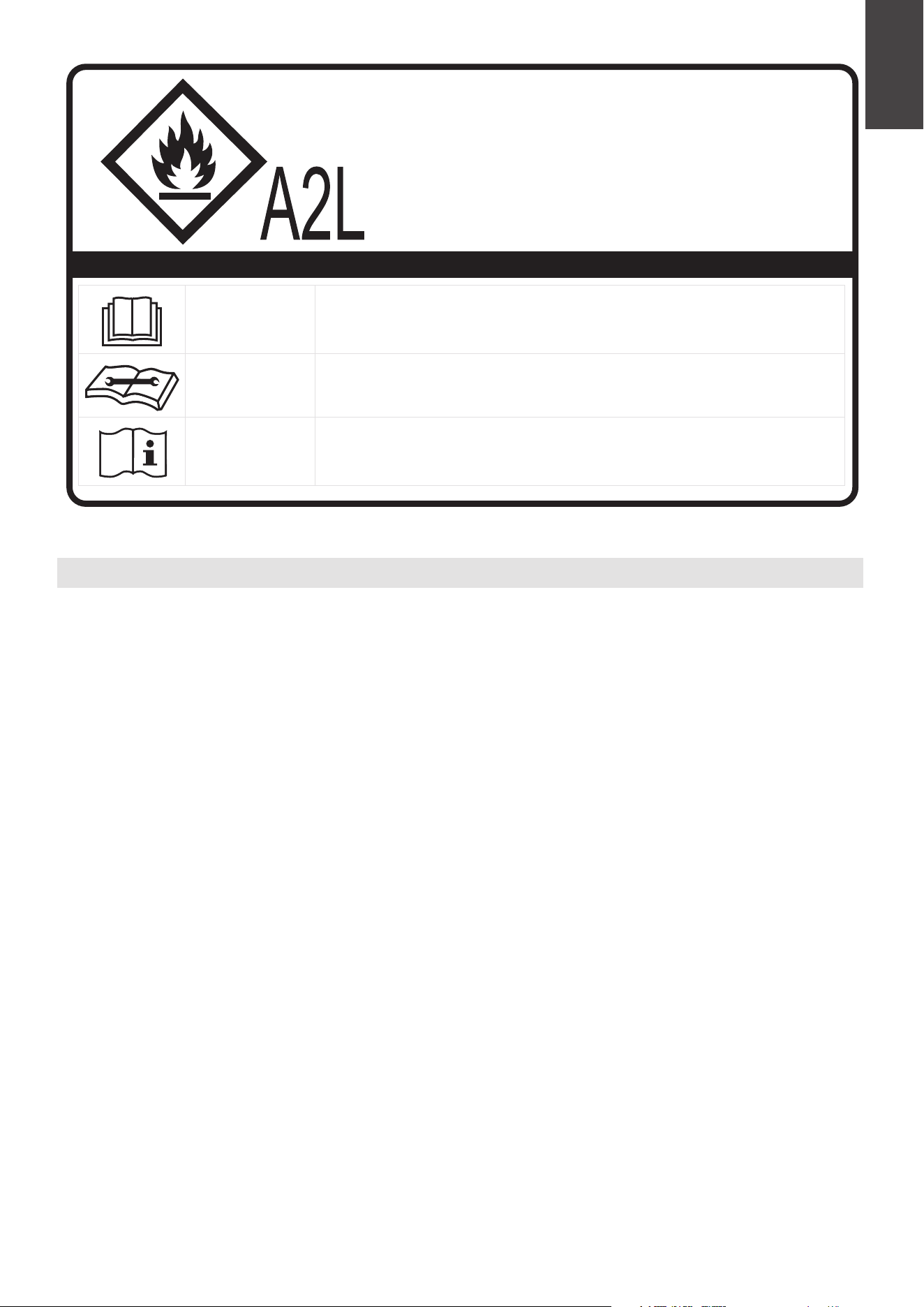
Inflamable
El aparato utiliza refrigerante R32.
• Cuando realice el mantenimiento o deseche el aparato, el refrigerante (R32)
deberá recuperarse adecuadamente y no deberá verterse directamente al aire.
• Deberá respetarse la normativa nacional sobre gases.
• Mantenga las aberturas de ventilación libres de obstrucciones.
• El aparato deberá almacenarse de manera que no se produzcan daños mecánicos.
• Advertencia de que el aparato debe almacenarse en una zona bien ventilada
donde el tamaño de la sala corresponda a la superficie de la sala especificada
para el funcionamiento.
• Toda persona que trabaje o intervenga en un circuito de refrigerante debe estar
en posesión de un certificado válido de una autoridad de evaluación acreditada
por la industria, que autorice su competencia para manipular refrigerantes de
forma segura de acuerdo con una especificación de evaluación reconocida por la
industria. Todo el entrenamiento debe seguir los requisitos del ANEXO HH de la
UL 60335-2-40 4ta Edición.
PRECAUCIÓN:
Riesgo de incendio
materiales inflamables
NOTA IMPORTANTE: Lea atentamente
este manualantes de instalar o poner
en funcionamiento su nuevo aparato.
Asegúrese de guardar este manual para
referencia futura.
Explicación de los símbolos que aparecen en la unidad
PRECAUCIÓN
Este símbolo indica que debe leerse atentamente el manual de
instrucciones.
PRECAUCIÓN
Este símbolo indica que el personal de servicio debe manipular este
equipo consultando el manual de instalación.
PRECAUCIÓN
Este símbolo indica que hay información disponible, como el manual
de instrucciones o el manual de instalación.
ADVERTENCIA:
• El mantenimiento sólo debe realizarse según las recomendaciones del fabricante
del equipo. El mantenimiento y la reparación que requieran la asistencia de otros
técnicos especializados se llevarán a cabo bajo la supervisión de la persona
competente en el uso de refrigerantes inflamables.
• NO modifique la longitud del cable de alimentación ni utilice un alargador para
alimentar la unidad.
• NO comparta una misma toma de corriente con otros aparatos eléctricos. Una
alimentación inadecuada puede provocar un incendio o una descarga eléctrica.
Siga atentamente las instrucciones de manipulación, instalación, limpieza y
mantenimiento del aparato para evitar cualquier daño o peligro.
Instrucciones
Importantes de
Seguridad
45

1. Transporte de equipos que contengan refrigerantes inflamables
Véase la normativa de transporte.
2. Señalización de los equipos mediante carteles
Véase la normativa local.
3. Eliminación de equipos que utilizan refrigerantes inflamables
Consulte la normativa nacional.
4. Almacenamiento de equipos/electrodomésticos
El almacenamiento del electrodoméstico debe ser de acuerdo con las
regulaciones o instrucciones aplicables, lo que sea más estricto.
Antes de empezar a trabajar en sistemas que contengan refrigerantes
inflamables, es necesario realizar comprobaciones de seguridad para garantizar
que se reduzca al mínimo el riesgo de ignición. Para la reparación del sistema
de refrigeración, se deberán tomar las siguientes precauciones antes de realizar
trabajos en el sistema.
Los trabajos se realizarán según un procedimiento controlado para minimizar el
riesgo de presencia de gases o vapores inflamables durante los mismos.
La protección del embalaje de almacenamiento debe realizarse de forma que
los daños mecánicos al equipo dentro del embalaje no provoquen una fuga de
la carga de refrigerante. La normativa local determinará el número máximo de
equipos que pueden almacenarse juntos.
5. Almacenamiento de material embalado (no vendido)
6. Información sobre el mantenimiento
1) Revisión del área
2) Procedimiento de trabajo
Todo el personal de mantenimiento y otras personas que trabajen en la zona
deberán recibir instrucciones sobre la naturaleza del trabajo que se está
realizando. Se evitará trabajar en espacios confinados. Se seccionará la zona
alrededor del espacio de trabajo. Cerciórese de que las condiciones dentro del
área son seguras mediante el control del material inflamable.
3) Área de trabajo general
.
Instrucciones
Importantes de
Seguridad
46
Ejemplos de tales procedimientos de trabajo son:
•
irrupción en el circuito frigorífico
• apertura de componentes sellados
• apertura de recintos ventilados
• No debe haber fuego abierto ni dispositivos como interruptores que puedan
generar chispas o arcos eléctricos cerca del electrodoméstico para evitar la
ignición del refrigerante inflamable utilizado. Por favor, siga cuidadosamente las
instrucciones al almacenar o mantener el electrodoméstico para evitar que se
produzcan daños mecánicos.
• No utilice medios para acelerar la operación de descongelación o para limpiar que
no sean los recomendados por el fabricante.
• El aparato debe almacenarse en una habitación sin fuentes de ignición de
funcionamiento continuo (por ejemplo: llamas abiertas, un aparato de gas en
funcionamiento) y fuentes de ignición o (por ejemplo: un calentador eléctrico en
funcionamiento) cerca del aparato. El aparato debe almacenarse en un local sin
fuentes de ignición en funcionamiento continuo (por ejemplo: llamas abiertas, un
aparato de gas en funcionamiento o un calentador eléctrico en funcionamiento).
• No lo perfore ni lo queme.
• Tenga en cuenta que los refrigerantes pueden no contener olor

Se comprobará la zona con un detector frigorífico adecuado antes y durante
el trabajo, para garantizar que el técnico es consciente de la existencia de
atmósferas potencialmente inflamables. Asegúrese de que el equipo de detección
de fugas utilizado es adecuado para su uso con refrigerantes inflamables, es
decir, que no produce chispas, está adecuadamente sellado o es intrínsecamente
seguro.
4) Verificación de la presencia de refrigerante
Si se va a realizar algún trabajo en caliente en el equipo de refrigeración o en
alguna de las piezas asociadas, deberá tenerse a mano el equipo de extinción de
incendios adecuado. Tenga un extintor de polvo seco o de CO2 junto al área de
carga.
5) Presencia de extintor de incendios
Asegúrese de que la zona está al aire libre o de que está adecuadamente
ventilada antes de entrar en el sistema o realizar cualquier trabajo en caliente.
Se mantendrá cierto grado de ventilación durante el período en que se realicen
los trabajos. La ventilación debe dispersar de una manera segura cualquier
refrigerante liberado y, preferiblemente, expulsarlo externamente a la atmósfera.
7) Zona ventilada
La reparación y el mantenimiento de los componentes eléctricos incluirán
revisiones iniciales de seguridad y procedimientos de inspección de los
componentes. Si existe un desperfecto que pueda comprometer la seguridad,
no se conectará ningún suministro eléctrico al circuito hasta que se solucione
9) Controles de los dispositivos eléctricos
Cuando se cambien componentes eléctricos, deberán ser aptos para el fin
previsto y cumplir las especificaciones correctas. Se seguirán en todo momento
las directrices de mantenimiento y servicio del fabricante. En caso de duda,
consulte al departamento técnico del fabricante. Se efectuarán las siguientes
verificaciones en las instalaciones que utilicen refrigerantes inflamables:
La carga real de refrigerante es acorde con el tamaño de la sala en la que están
instaladas las piezas que contienen refrigerante;
La maquinaria de ventilación y las salidas funcionan adecuadamente y no están
obstruidas; Si se utiliza un circuito de refrigeración indirecto, se comprobará la
presencia de refrigerante en el circuito secundario; El marcado del equipo sigue
siendo visible y legible. La tubería o los componentes frigoríficos se instalarán en
un lugar en el que sea improbable que queden expuestos a cualquier sustancia
que pueda corroer los componentes que contengan refrigerante, a menos que
los componentes estén fabricados con materiales que sean intrínsecamente
resistentes a la corrosión o estén convenientemente protegidos contra ésta.
8) Controles del equipo frigorífico
Ninguna persona que realice trabajos en relación con un sistema de refrigeración
que implique la exposición de tuberías que contengan o hayan contenido
refrigerantes inflamables utilizará fuentes de ignición de tal manera que pueda
producirse un riesgo de incendio o explosión. Todas las posibles fuentes de
ignición, incluido el consumo de cigarrillos, deberán mantenerse suficientemente
alejadas del lugar de instalación, reparación, retirada y eliminación, durante las
cuales es posible que se libere refrigerante inflamable al espacio circundante.
Antes de empezar a trabajar, se deberá inspeccionar el área alrededor del equipo
para asegurarse de que no hay riesgos de inflamación o ignición. Se colocarán
señales de prohibido fumar.
6) Ausencia de fuentes de ignición
47
Instrucciones
Importantes de
Seguridad

7. Reparación de componentes sellados
8. Reparación de componentes intrínsecamente seguros
9. Cableado
10. Detección de refrigerantes inflamables
Compruebe que el cableado no estará sometido a desgaste, corrosión, presión
excesiva, vibración, bordes afilados o cualquier otro efecto ambiental adverso.
La comprobación también tendrá en cuenta los efectos del envejecimiento o la
vibración continua de fuentes como compresores o ventiladores.
En ningún caso se utilizarán fuentes potenciales de ignición en la búsqueda o
detección de fugas de refrigerante. No se utilizará un soplete de halogenuros (ni
ningún otro detector que utilice una llama desnuda).
Los siguientes métodos de detección de fugas se consideran aceptables para
los sistemas que contienen refrigerantes inflamables. Se utilizarán detectores
electrónicos de fugas para detectar refrigerantes inflamables, pero es posible
que la sensibilidad no sea la adecuada o que haya que recalibrarlos.
(El equipo de detección se calibrará en una zona libre de refrigerantes).
Asegúrese de que el detector no es una fuente potencial de ignición y es adecuado
para el refrigerante utilizado. El equipo de detección de fugas se ajustará a un
porcentaje del LFL del refrigerante y se calibrará para el refrigerante empleado y
se confirmará el porcentaje adecuado de gas (25 % como máximo). Los líquidos de
detección de fugas son adecuados para la mayoría de los refrigerantes, pero debe
evitarse el uso de detergentes que contengan cloro, ya que éste puede reaccionar
con el refrigerante y corroer las tuberías de cobre.
Si se sospecha una fuga, se retirarán/extinguirán todas las llamas desnudas. Si se
detecta una fuga de refrigerante que requiera soldadura, se recuperará todo el
refrigerante del sistema o se aislará (cerrando las válvulas) en una parte del sistema
alejada de la fuga. La extracción del refrigerante se realizará de acuerdo con la
11. Remoción y evacuación
Al acceder al circuito de refrigeración para realizar reparaciones, o con cualquier
otro propósito, se seguirán los procedimientos convencionales.
Sin embargo, en el caso de refrigerantes inflamables es importante seguir las
mejores prácticas, ya que la inflamabilidad es un factor a tener en cuenta. Se
seguirá el siguiente procedimiento:
a) elimine el refrigerante de forma segura siguiendo la normativa local y nacional;
b) purgue el circuito con gas inerte;
c) evacuar (opcional para A2L);
d) purgar con gas inerte (opcional para A2L);
e) abra el circuito cortándolo o soldándolo.
48
Instrucciones
Importantes de
Seguridad
satisfactoriamente. Si el fallo no puede corregirse inmediatamente pero es
necesario continuar el funcionamiento, se utilizará una solución temporal
adecuada. Esto se comunicará al propietario del equipo para que todas las partes
estén informadas. Las verificaciones iniciales de seguridad incluirán:
Que los condensadores estén descargados: esto se hará de forma segura para
evitar la posibilidad de chispas; Que no haya componentes eléctricos en tensión
ni cableado expuesto mientras se carga, recupera o purga el sistema; Que haya
continuidad de la conexión a tierra.
Si no se permite la ventilación según los códigos locales y nacionales, la carga de
refrigerante debe recuperarse en los cilindros de recuperación correctos. Para
los aparatos que contienen refrigerantes inflamables, el sistema debe purgarse

a) Deberá familiarizarse con el equipo y su funcionamiento.
b) Aislar eléctricamente el sistema.
c) Antes de intentar el procedimiento asegúrese de que: Se dispone de equipos
de manipulación mecánica, si es necesario, para manipular los cilindros de
refrigerante; todo el equipo de protección personal esté disponible y se utilice
correctamente; el proceso de recuperación esté supervisado en todo momento
por una persona competente; el equipo de recuperación y los cilindros se
ajusten a las normas apropiadas.
d) Bombee el sistema de refrigeración, si es posible.
e) Si no es posible lograr el vacío, consiga un colector para poder extraer el
refrigerante de las distintas partes del sistema.
f) Asegúrese de que el cilindro esté ubicado en la balanza antes de proceder a la
recuperación.
g) Ponga en marcha la máquina de recuperación y hágala funcionar de acuerdo
con las instrucciones.
12. Procedimientos de carga
Además de los procedimientos de carga convencionales, se seguirán los siguientes
requisitos. Al utilizar el equipo de carga, asegúrese de que no se produce
contaminación de los distintos refrigerantes. Las mangueras o líneas serán lo
más cortas posible para minimizar la cantidad de refrigerante que contienen. Las
botellas se mantendrán enuna posición adecuada de acuerdo con las instrucciones.
Verifique que el sistema de refrigeración esté conectado a tierra antes de recargarlo
con refrigerante. Etiquete el sistema cuando la carga esté completa (si no lo está
ya). Deberán extremarse las precauciones para no llenar en exceso el sistema
de refrigeración. Antes de recargar el sistema, se someterá a una prueba de
presión con nitrógeno libre de oxígeno. El sistema se someterá a una prueba de
estanqueidad una vez finalizada la carga de forma previa a la puesta en servicio.
Se realizará una prueba de fugas de seguimiento antes de abandonar el lugar de
trabajo.
13. Desmantelamiento
Antes de llevar a cabo este procedimiento, es esencial que el técnico esté
completamente familiarizado con el equipo y todos sus detalles. Se recomienda
como buena práctica que todos los refrigerantes se recuperen de forma segura.
Antes de realizar la tarea, se tomará una muestra de aceite y refrigerante por si
fuera necesario realizar un análisis antes de reutilizar el refrigerante recuperado.
Es esencial que se disponga de energía eléctrica antes de comenzar la tarea.
49
Instrucciones
Importantes de
Seguridad
con nitrógeno libre de oxígeno para hacer que el aparato sea seguro para los
refrigerantes inflamables. Este proceso puede necesitar repetirse varias veces. No
se debe utilizar aire comprimido u oxígeno para purgar sistemas de refrigerante.
Para los aparatos que contienen refrigerantes inflamables, la purga de
refrigerantes se logrará rompiendo el vacío en el sistema con nitrógeno libre de
oxígeno y continuando a llenar hasta que se alcance la presión de trabajo, luego
se ventilará a la atmósfera y finalmente se reducirá a un vacío (opcional para A2L).
Este proceso se repetirá hasta que no haya refrigerante en el sistema (opcional
para A2L). Cuando se use la carga final de nitrógeno libre de oxígeno, el sistema
se ventilará a la presión atmosférica para permitir que se realice el trabajo.
La salida de la bomba de vacío no debe estar cerca de ninguna fuente potencial
de ignición, y debe haber ventilación disponible.

h) No sobrellene los cilindros. (No más del 80 % de volumen de carga líquida).
i) No exceda la presión de trabajo máxima del cilindro, ni siquiera temporalmente.
j) Una vez que los cilindros se hayan llenado correctamente y el proceso haya
finalizado, asegúrese de que los cilindros y el equipo se retiren rápidamente del
lugar y de que se cierren todas las válvulas de aislamiento del equipo.
k) El refrigerante recuperado no debe cargarse en otro sistema de refrigeración a
menos que se haya limpiado y revisado.
14. Etiquetado
El equipo se etiquetará indicando que ha sido retirado de servicio y vaciado de
refrigerante. La etiqueta deberá estar fechada y firmada.
Asegúrese de que el equipo tenga etiquetas que indiquen que contiene
refrigerante inflamable.
15. Recuperación
Al retirar el refrigerante de un sistema, ya sea para su mantenimiento o
desmantelamiento, se recomienda como buena práctica que todos los refrigerantes
se retiren de forma segura.
Al trasvasar refrigerante a botellas, asegúrese de que sólo se utilizan botellas de
recuperación de refrigerante adecuadas.
Asegúrese de que se dispone del número correcto de botellas para la carga total
del sistema. Todos los cilindros que se utilicen estén designados para el refrigerante
recuperado y etiquetados para ese refrigerante (es decir, cilindros especiales
para la recuperación de refrigerante). Los cilindros deberán estar completos con
válvula de alivio de presión y válvulas de cierre asociadas en buen estado de
funcionamiento. Los cilindros vacíos deben evacuarse y, si es posible, enfriarse
antes de la recuperación. Los equipos de recuperación deben estar en buen estado
de funcionamiento, contar con un conjunto de instrucciones que esté a mano y
ser aptos para la recuperación de refrigerantes inflamables. Además, es necesario
contar con un conjunto de balanzas calibradas que funcionen correctamente. Las
mangueras deberán estar completas, con acoplamientos de desconexión sin fugas y
en buen estado.
Antes de utilizar el equipo de recuperación, compruebe que funciona
correctamente, que se ha sometido a un mantenimiento adecuado y que todos los
componentes eléctricos asociados están sellados para evitar la ignición en caso
de fuga de refrigerante. En caso de duda, consulte al fabricante. El refrigerante
recuperado se devolverá al proveedor en el cilindro de recuperación correcto, al que
se adjuntará la correspondiente nota de transferencia de residuos.
No mezcle refrigerantes en las unidades de recuperación y especialmente en los
cilindros. Si se deben retirar los compresores o su aceite, asegúrese de que hayan
sido evacuados a un nivel aceptable para que no quede refrigerante inflamable
en el lubricante. El proceso de evacuación se llevará a cabo antes de devolver el
compresor a los proveedores. Para acelerar este proceso, solamente se empleará el
calentamiento eléctrico del cuerpo del compresor. Sea cuidadoso al drenar el aceite
del sistema.
50
Instrucciones
Importantes de
Seguridad
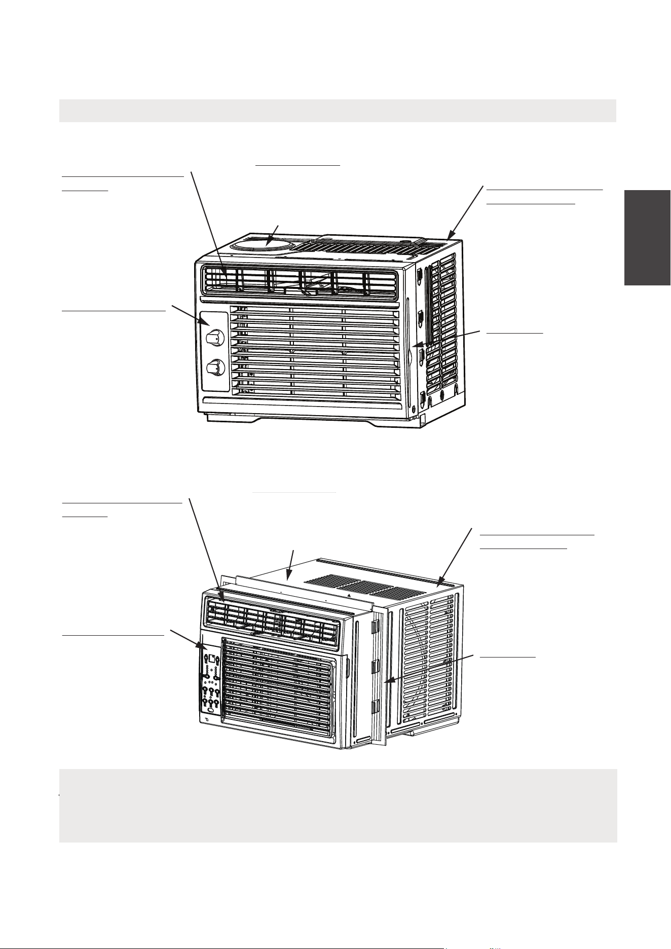
INSTRUCCIONES DE OPERACIÓN
Sonidos Normales
Instrucciones
de Operación
Gorgoteo/Silbido
El sonido de
gorgoteo/silbido
podría ser la
consecuencia de que
el refrigerante pasa
por el evaporador
durante su operación
normal.
Sonido del Corriente
del Aire
En la frontera de la
unidad, podría oir un
sonido del corriente
del aire
debido al
movimiento del
ventilador.
Sonido Agudo
Un compresor con alta
sonido agudo durante su
ciclo de refrigeración.
Vibración
vibrar y hacer ruido
por una débil pared o
construcción de
ventana o una
instalación incorrecta.
El Sonido de Ping o
el Conmutador
Las gotas del agua
cayendo sobre el
condensador podría
causar el sonido de
ping o el conmutador.
NOTA
Todas las ilustraciones en esta manual son para explicar sólo. Su aire acondicionado
podría ser un poco diferente. Prevalezca a la forma real.
Gorgoteo/Silbido
El sonido de
gorgoteo/silbido
podría ser la
consecuencia de que
el refrigerante pasa
por el evaporador
durante su operación
normal.
Sonido del Corriente
del Aire
En la frontera de la
unidad, podría oir un
sonido del corriente
del aire debido al
movimiento del
ventilador.
Sonido Agudo
Un compressor con alta
eficiencia podrá tener un
eficiencia podrá tener un
sonido agudo durante su
ciclo de enfrigeración.
Vibración
vibarar y hacer ruido
La unidad podrá
La unidad podrá
por una débil pared o
construcción de
ventana o una
instalación incorrect.
El Sonido de Ping o
el Conmutador
Las gotas del agua
cayendo sobre el
consensador podría
causar el sonido de
ping o el conmutador.
MAW05M Model
MAW05R/MAW06R Models
51
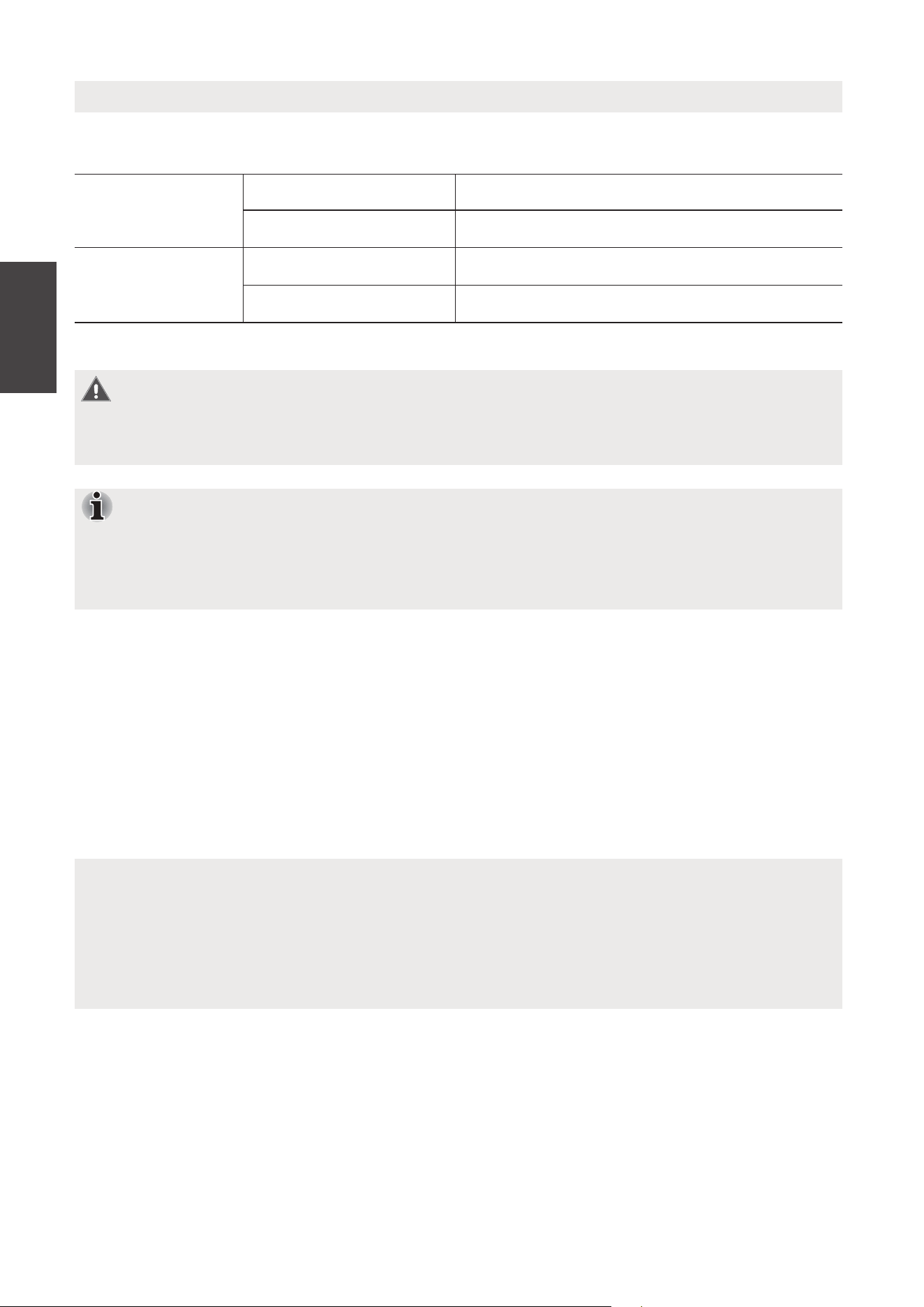
NOTA
El circuito frío tiene un inicio automático de 3 minutos retrasado si la unidad se
apaga y enciende rápidamente. Esto evita el sobrecalentamiento del compresor y
el posible disparo del disyuntor.
Operación del aire acondicionado
ADVERTENCIA
Para reducir el riesgo de incendio, descarga eléctrica o lesiones a personas o
propiedades, lea las INSTRUCCIONES DE SEGURIDAD antes de operar este aparato.
PARA COMENZAR A OPERAR RÁPIDAMENTE EL ACONDICIONADOR DE AIRE, SIGA
ESTOS PASOS:
1. Ajuste una configuración de temperatura más fría.
2. Ajuste el control del selector en la configuración más alta de COOL.
3. Ajuste la rejilla para un flujo de aire cómodo (consulte rejillas direccionales de aire).
4. Una vez que la habitación se siente más fría, ajuste a la configuración que
encuentre más cómoda.
5. Asegúrese de que el flujo de aire dentro y fuera no esté o
bstruido por nada.
Antes de comenzar, familiarícese completamente con el panel de control como
se muestra a continuación y con todas sus funciones, luego siga el símbolo de las
funciones que desee. La unidad puede controlarse solo con el panel de control de
la unidad o con el control remoto.
NOTAS
• La humedad relativa de la habitación debe ser inferior al 80%. Si la unidad se
utiliza en un estado con una humedad relativa superior al 80%, habrá agua
condensada en la superficie de la unidad.
• El rendimiento podría reducir fuera de estas temperaturas operativas.
Este aire acondicionado es diseñado para funcionar bajo las siguientes condiciones:
Funcionamiento
de enfriamiento
Temperatura exterior 64-109°F/18-43°C
Temperatura interior 62-90°F/17-32°C
Funcionamiento
de calefacción
Temperatura exterior 23-76°F/-5-24°C
Temperatura interior 32-80°F/0-27°C
Instrucciones
de Operación
52
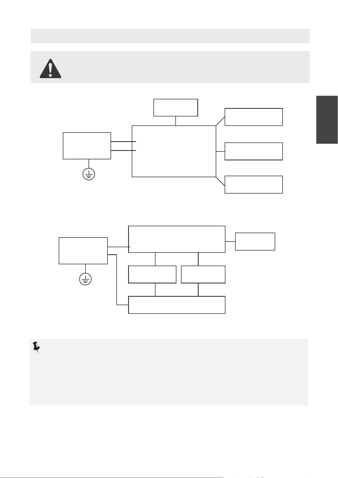
Trabajo Electrónico
ADVERTENCIA :
ANTES DE REALIZAR CUALQUIER TRABAJO ELÉCTRICO O DE
CABLEADO, APAGUE LA ENERGÍA PRINCIPAL DEL SISTEMA.
Control principal
compresor
El motor del
ventilador
La pantalla
Fuente de
alimentación
L/AC L/L1/L-IN
N/AC N/L2/N-IN
Otras
MAW05R/06R Modelo
AVISO :
Por favor, siga estrictamente la etiqueta de cableado adjunta a la máquina
para todas las conexiones de cableado.
El diagrama de cableado puede variar para diferentes unidades. Por favor,
consulte el diagrama de cableado en la máquina que ha comprado.
El diagrama de cableado anterior es una versión simplificada solo para fines
ilustrativos preliminares.
Interruptor
Condensador
El motor del
ventilador
L
0
N
Fuente de
alimentación
Otras
MAW05M Modelo
Compresor
Instrucciones
de Operación
53
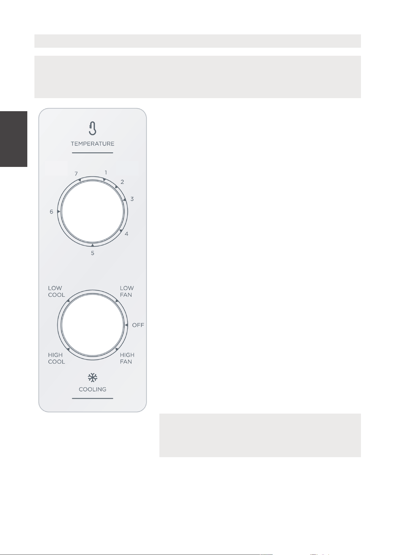
Instrucciones
de Operación
Características del Aire Acondicionado - MAW05M Model
MODO FRÍO
El nivel frío está elegido con girando la perilla agujas
del reloj hasta una ubicación adecuada.
Alto Enfriamiento
Tiene el máximo efecto de enfriamiento y flujo de aire.
Bajo Enfriamiento
Tiene el mínimo efecto de enfriamiento y flujo de aire.
CONTROL DE LA UNIDAD
NOTA
La caracteristica del control en este manual es responsible de muchos modelos
disponibles. Su modelo podría ofrecer una caracteristica un poco diferente
NOTA
Al seleccionar la velocidad del ventilador, el
compresor no funcionará.
TERMOSTATO
El termostato se sirve para ajustar la temperatura de
la habitación cuando la unidad está operando bajo el
MODO FRÍO.
Para cambiar la temperatura de la habitación, gire
el interruptor del termostato a una opción deseada.
Después de elegir la temperatura, el termostato
empezará y parará automáticamente el compresor
con el fin de mantener la temperatura deseada.
Gire el selector del termostato en sentido horario
para una opción de más fría. Programación de más
frío le ofrecerá una temperatura más baja. Gire el
selector del termostato contra el sentido horario
para una opción de menos fría. Programación de
menos fría le ofrecerá una temperatura más alta en
la habitación.
MODO DE VENTILADOR
Gire la perilla en sentido antihorario para seleccionar
su elección de velocidades del ventilador para la
circulación del aire
MAX
COOL
MIN
COOL
54
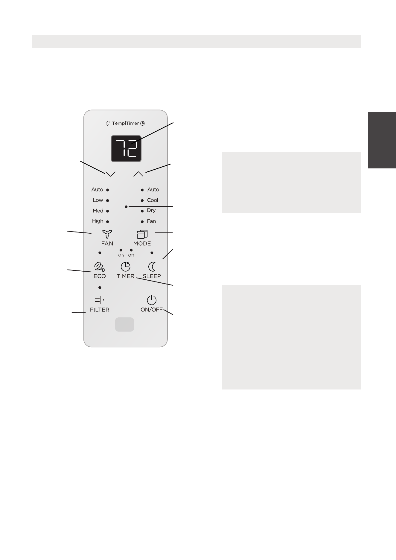
Instrucciones
de Operación
INSTRUCCIONES DE LA OPERACIÓN DEL CONTROL ELECTRÓNICO
Antes de empezar, debe familiarizarse completamente con el panel de control y todas
sus funciones como se muestra abajo, despúes sigue los símbolos para las funciones
que desea. La unidad podría ser controlado por el control sólo o con el remoto.
Características del Aire Acondicionado - MAW05R/MAW06R Models
PARA ENCENDER O APAGAR LA
UNIDAD:
Presiona el botón ON/OFF
para encender o apagar.
A CAMBIAR LAS OPCIONES DE LA
TEMPERATURA:
Presiona el botón UP/DOWN
para cambiar las opciones de
la temperatura.
PARA MODIFICAR LA VELOCIDAD
DEL VENTILADOR:
Presiona el botón a elegir la
velocidad del ventilador en cuatro
grados - Auto, Bajo, Med o Alto.
Cada vez presiona el botón, se
modifica el modo de la velocidad
del ventilador. Bajo el Modo Seco, la
velocidad está controlado en Bajo
40
automáticamente.
NOTE
La unidad iniciará automáticamente
la función de Ahorro de Energía
bajo los modos de Frío, Seco, Auto
(Sólo Auto-Frio y Auto-Ventilador).
NOTE
Pulse o mantenga presionando el
botón UP or DOWN hasta se
muestra la temperatura que quiere.
La mantiene automáticamente esta
temperatura en cualquier lugar
entre 62° F (17°C) y 86°F (30°C). Si
quiere saber la temperatura actual
de la habitación, elige la Operación
de sección Fan Only.
CONTROL DE LA UNIDAD
Muestra la
temperatura o
tiempo o
códigos de
error
Ajuste la
temperatura
o reloj
Ajuste la
temperatura
o reloj
Compruebe el
filtro botón
RESET
Modo de
ahorro de
energia
Establece el
modo
Activa el
temporizador
Modo de sueño
Encende
o apaga la
unidad
Establece la
velocidad del
ventilador
Comfort
Sense
ComfortSense
55

Instrucciones
de Operación
A ELEGIR EL MODO OPERATIVO:
A elegir el modo operativo, presiona el
Esta función se puede activar SOLAMENTE
desde el control remoto.
El control remoto enviará esta señal al aire
acondicionado cada intervalo de 3 minutos
hasta que presione el botón Sígueme
nuevamente. Si la unidad no recibe la señal
Sígueme durante cualquier intervalo de
7 minutos, la unidad emitirá un pitido para
indicar que el modo Sígueme ha terminó.
botón Modo. Cada vez presiona el botón,
selecciona un modo siguiendo orden
como Auto, Frío, Seco y Ventilador.
La luz del indicador ilumina y mantiene
una vez que selecciona el modo. La
unidad empieza la función de ahorrar la
energía bajo los modos de Frío, Seco,
Auto (Sólo Auto-Frío y Auto-Ventilador).
PARA OPERAR BAJO LA FUNCIÓN AUTO:
• Cuando elige el modo AUTO
del aire acondicionado, elegirá
automáticamente operación como
enfriamiento, calefacción (fuera
el modo de sólo-frío), o modo de
ventilador sólo según la temperatura
elegida y la actual de la habitación.
• El aire acondicionado controlará
la temperatura de la habitación
automáticamente alrededor de la
temperatura elegida por usted.
• In this mode, the fan speed cannot be
adjusted, as it’s automatically controlled
according to the temperature setting
and room temperature.
FUNCIÓN DE INSPECCIÓN:
Presiona el botón Filter comprueba
de filtro para iniciar esta función. Esta
función es un recordatorio para limpiar
el filtro de aire para su funcionamiento
eficaz. El LED (luz) ilumina despúes de
250 horas de función. Para encenderla
despúes de la limpieza, presiona el
botón Check Filter y la luz va a apagar.
La función ComfortSense permite que el
control remoto mida la temperatura en
su ubicación actual. Cuando utilice las
funciones AUTO, COOL o HEAT, la
medición de la temperatura ambiente
desde el control remoto (en lugar de
desde la unidad interior) permitirá que
el aire acondicionado optimice la
temperatura a su alrededor y garantice
FUNCIÓN DE AHORRAR LA ENERGÍA:
Presiona botón de ahorrar la energía
para iniciar esta función. Esta función es
diponible bajo los modos Frío, Seco, Auto
(Sólo Auto-Frío y Auto-Ventilador). El
ventilador continua funcionar 3 minutos
despúes de que el compresor apaga.
Entonces el ventilador gira 2 minutos a
cada 10 minutos de intervalo hasta que
la temperatura interior llega a la puesta,
cuando el compresor vuelve a funcionar
y empieza a enfriar.
FUNCIÓN DURMIENTA:
Presiona el botón durmiento
a iniciar el modo durmiento. Bajo
este modo la temperatura selecciona
incrementará a 2°F/1 (o 2)°C 30
minutos despúes de elegir el modo.
La temperatura va a incrementar un
otro 2°F/1 (o 2)°C despúes de 30
minutos adicional. Esta temperatura va
a mantener 7 horas antes de volver a
su temperatura elegida originalmente.
El modo durmiento puede ser
cancelado en cualquier momento
durante su función con presionando
el botón durmiento otra vez.
PARA OPERAR BAJO EL MODO
VENTILADOR SÓLO:
• Utilice esta función solamente cuando
no quiere enfriar, sirve como una
circulación de aire de la habitación
o para extraer el aire viciado (bajo
algunos modos). (Recuerde abrir el
respiradero durante esta función, pero
mantengalo cerrado durante la función
de enfriar para una eficiencia máxima
de enfriamiento.) Puede elegir cualquier
velocidad del ventilador que prefiere.
COMFORTSENSE
56
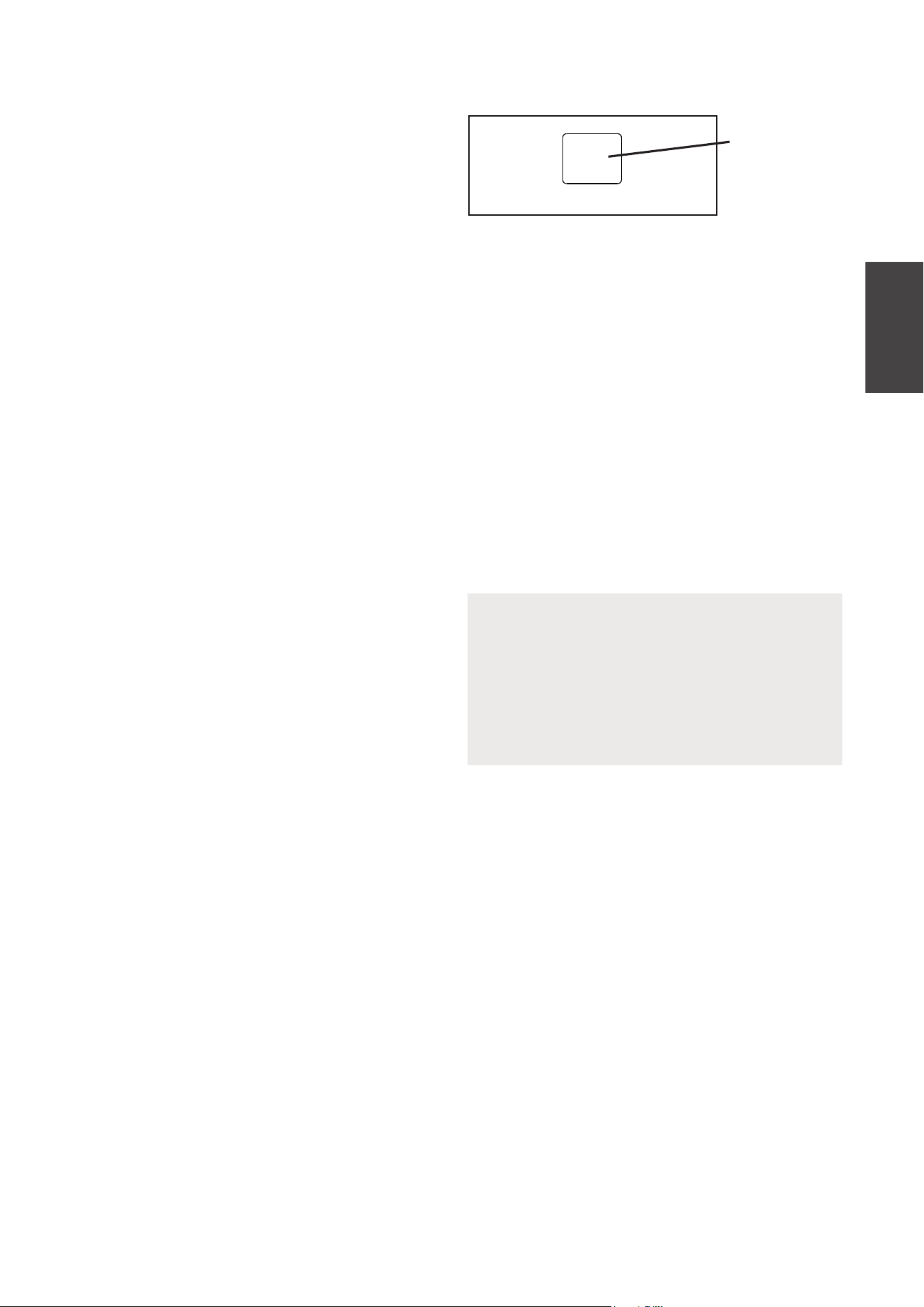
Instrucciones
de Operación
NOTA
Si la unidad falla inesperadamente
por el corte de suministro eléctrico,
volverá a encender con la opción de
la función previa automáticamente
cuando el suministro reanuda.
PANTALLAS:
Muestra la temperatura en “°C” o “°F” y
las opciones del Auto-reloj. Cuando bajo
el modo de ventilador sólo, muestra la
temperatura actual de la habitación.
Los códigos de error:
AS
- Sensor de error de la temperatura de
la habitación desenchufe la unidad y
conéctala otra vez. Si repite este error,
llama al servicio.
ES - Sensor de error del evaporador de la
temperatura. Desenchufe la unidad y
conéctala otra vez. Si el error repite,
llama al servicio.
PANTALLAS
RELOJ: FUNCIÓN DE AUTO EMPEZAR O
TERMINAR
•
•
•
•
•
42
Cuando enciende la unidad, primero
presiona el botón reloj, el indicador
TIMER ON ilumina. Este indica que el
programa de Auto Empezar está
iniciado.
Cuando el tiempo del TIMER ON
muestra, Presiona el botón otra vez,
el indicador TIMER OFF ilumina, i
ndicando que el programa de Auto
Terminar está iniciado.
Pulse o mantenga pulsando el botón
UP or DOWN button para cambiar el
tiempo de Auto por incrementos de
0.5 horas hasta 10 horas, entonces
una hora incrementos hasta 24 horas.
El controlo contará regresiva del
tiempo restante hasta el inicio.
El tiempo elegido registrará en
5 segundos, y la sistema volverá
automáticamente mostrar la
temperatura anterior elegida o actual
de la habitación una vez la unidad está
encendida. (Cuando apaga la unidad,
no muestra nada.)
Enciende la unidad o apagala en
cualquier tiempo o modificar el reloj a
0.0, va a cancelar el programa de Auto
Empezar o Termimar el reloj.
PARA OPERAR BAJO EL MODO SECO:
• Durante esta función, la pantalla
mostrará la temperatura actual de la
habitación, no la temperatura elegida,
como el modo frío.
• Bajo el modo de ventilador sólo, la
temperatura no será ajustado.
• Bajo este modo, el aire acondicionado
poco a poco funciona en una manera
de deshumidificador. Como el espacio
condicionado es cerrado o sellado,
un cierto grado de enfriamiento
continuará.
57
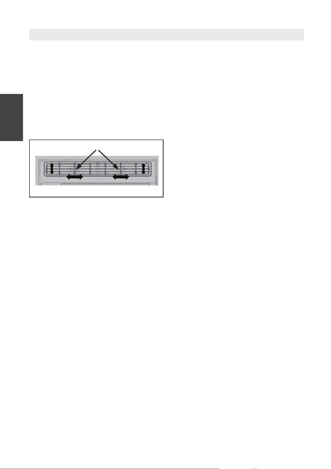
Instrucciones
de Operación
REJILLAS DE LA DIRECCIÓN DEL AIRE
Las rejillas le permitirán dirigir el flujo de
aire hacia arriba o hacia abajo y hacia la
izquierda o hacia la derecha en toda la
habitación según sea necesario.
Gire las rejillas horizontales hasta obtener
la dirección arriba / abajo deseada.
Mueva la (s) palanca (s) de lado a lado
hasta obtener la dirección izquierda /
derecha deseada.
Información Adicional Que Debe Saber
Ahora es dueño del producto operativo, hay más funciones bajo su controlo que
debe familizarse con:
• El circuito de Frío tiene un retraso de 3 minutos si la unidad enciende y apaga
rápidamente. Este evita el sobrecalentamiento del compresor y la posiblidad del
disparo del disyuntor. El ventilador continuará funcionando durante este tiempo.
• El control es capaz de mostrar la temperatura en grados Fahrenheit o grados
Celsius. Para cambiar uno a otro, presiona y mantenga pulsando los botones
UP/DOWN de Temp/Timer al mismo tiempo durante 3 segundos.
Dirección del Aire
Palancas
58
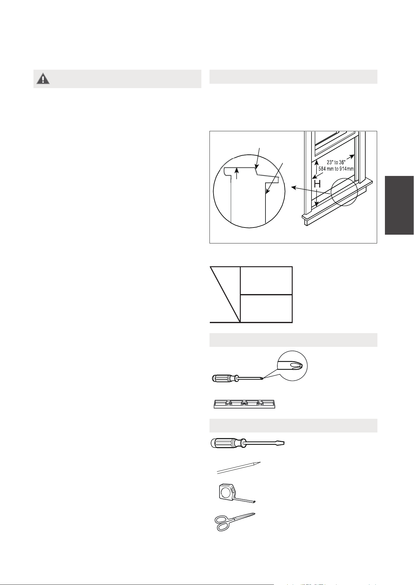
INSTRUCCIONES DE INSTALACIÓN
Model
5000~6000
BTU/h
H
13”
(330mm)
Su aire acondicionado es diseñado para
instalar en ventanas estandar de doble
panel con un ancho de apertura de 23 a 36
pulgadas (584mm a 914mm).
Acodo
VENTANA DE MADERA
INTERIOR
PARED
EXTERIOR
PARED
DENTRO CERCA
VENTANA umbral
Tabla 1
Herramientas que Necesite
Requisitos de la Ventana
Herramientas Quizä Necesite
Destornillador
Rango
Destornillador
Lápiz
Regla o cinta métrica
Tijera o cuchillo
WARNING - Antes de Empezar
Lea esta instrucción completamente y
con mucho cuidado.
• IMPORTANTE - Guarda esta
instrucción para uso del inspector
local.
• IMPORTANTE - Consulte todos los
códigos y ordenanzas vigentes.
• Nota para instalar - Asegúrese de
dejar las instrucciones al cliente.
• Nota para el cliente - Guarda la
instrucción para el uso futuro.
• Nivel de habilidad - Para instalarla
require una habilidad básica
mecánica.
• Plazo de ejecución -
Approximadamente 1 hora.
Le recomendamos que dos personas lo
instalen.
Una instalación correcta es la
responsabilidad del instalador.
El fallo del producto por una instalación
incorrect no está incluído en la garantía.
DEBE usar todas las partes
suministradas y los productos de
instalación correctamente según la
descripción en la instrucción cuando
instala esta aire acondicionado.
Nunca, en ningún caso corta o remueve
la tercera (tierra) clavija del cable de
energía.
No lo cambie el enchufe en el cable de
energía del aire acondicionado.
Cableado domestico de aluminio podría
causar problemas especiales - consulte
a un electricista calificado.
Al manipular la unidad, tenga cuidado
de evitar cortes ...
Instrucciones
de Instalción
59
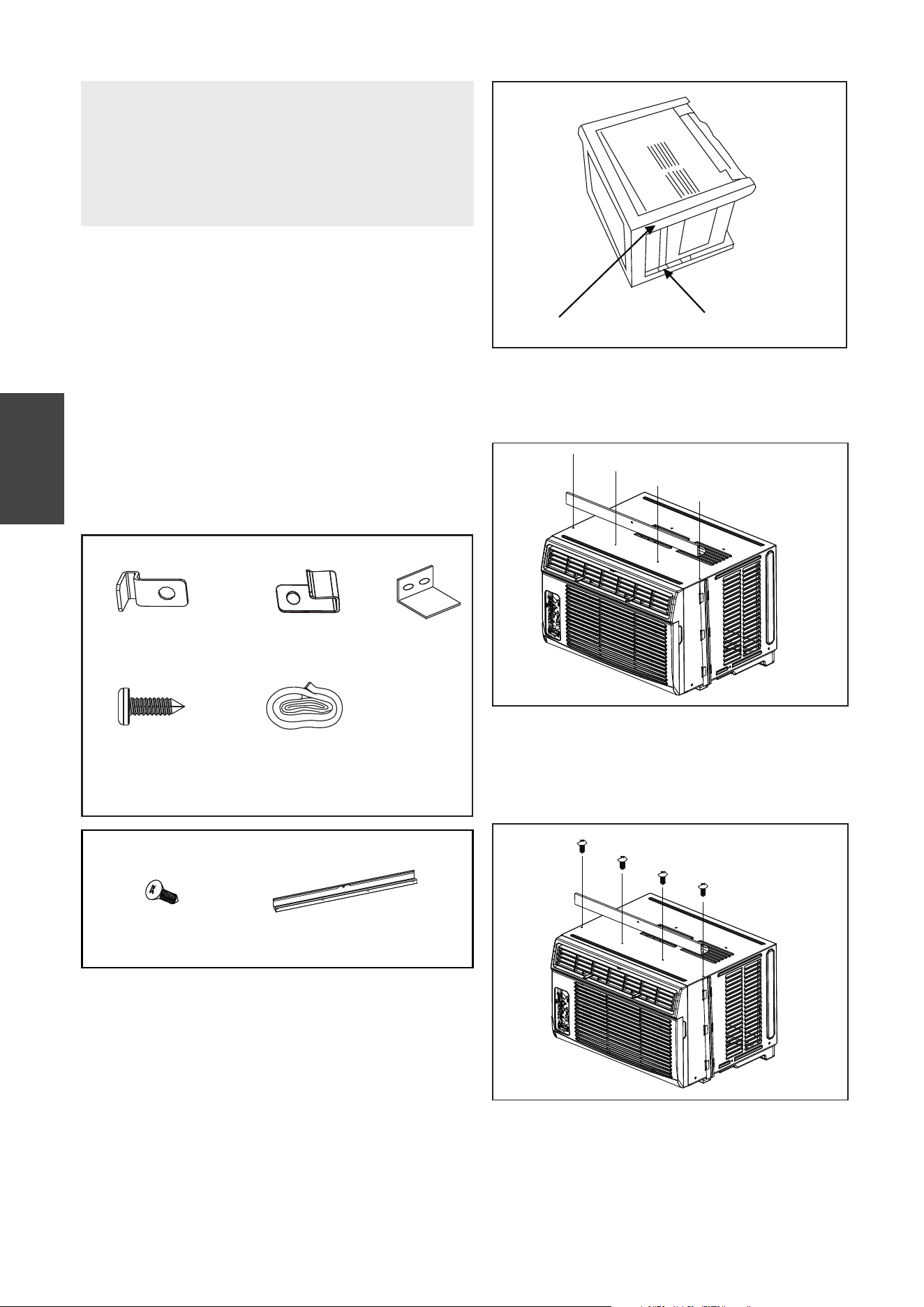
1. PREPARE LA VENTANA
El marco inferior debe poder abrirse un
espacio suficiente para la limpieza con una
apertura (H) de los siguientes tamaños
(consulte la Tabla 1).
Rejillas laterales y la parte trasera de la AC
debe tener un espacio libre de aire que
permite suficiente flujo de aire através del
condensador, para la eliminación del calor.
La parte trasera de la unidad debe estar
fuera, no dentro de un edificio ni garaje.
NOTA
Guarde los cartones y estas instrucciones
de instalación para el uso futuro. El carton
es la major manera a almacenar la unidad
en el invierno o cuando no lo use.
2. PREPARA EL AIRE ACONDICIONADO
A: Remueva el aire acondicionado desde
Antes de instalar la unidad, el riel superior
debe montarse en la unidad.
la caja y coloquelo sobre una superficie
plana.
B: Retire el carril superior de la parte
posterior del material de envase como
se muestra en Fig. A.
C: Alinee el agujero en la barra superior
con los de la parte superior de la
unidad, como se muestra en la Fig. B.
D: Instala el carril superior a la unidad
con un tornillo de 3/8” (9.5mm)
como se muestra en la Fig. C.
Embalaje Carril superior
Fig. A
Fig. B
Fig. C
Instrucciones
de Instalción
Mounting Hardware
3/4’’ (or 1/2”)
Screws
(7)
Lock Frame
(For Wooden windows)
(2)
Sash Lock
(1)
Window sash
seal foam
(1)
Lock Frame
(For Vinyl-Clad windows)
(2)
Accesorios de montaje
3/4” (o 1/2”)
Tornillos
(7)
Bloqueo de marco
(para ventanas de
madera) (2)
Bloqueo de
la ventana
(1)
Bloqueo de marco
(para ventanas de vinil
revestido) (2)
Sello de espuma
Guillotina
de ventana
(1)
3/8” Screws
(4)
Top Rail
(1)
Top Rail Hardware
Hardware del carril superior
Carril superior
(1)
3/8” Tornillos
(4)
60
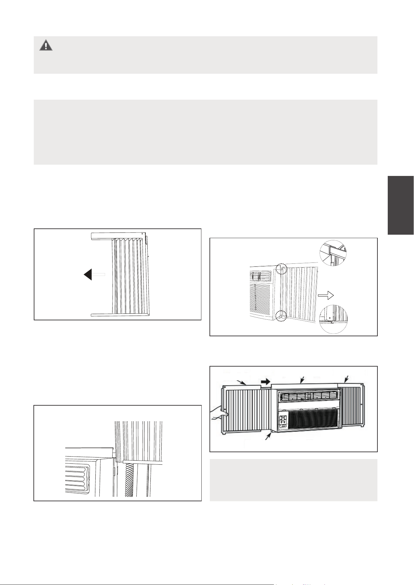
Instrucciones
de Instalción
Para su seguridad, todos los cuatro (4) tornillos DEBEN estar bien sujetos.
A.
NOTA
El carril superior y los paneles deslizantes en cada lado se sirve para ofrecer
un paso adecuado a la parte trasera de 5/16” (8mm). Es necesario para la
utilización del agua condensada y el drenaje adecuado. Si no use los paneles
laterales por ningún razón, debe mantener este paso hacia la parte trasera.
3. INSTALAR LOS PANELES DEL AIRE ACONDICIONADO
NOTA
Si la ventana de la tormenta bloquea
AC, consulte Fig. 11.
C. Una vez el panel está instalado en un
lado del gabinete, asegúrese de que
esté correctamente dentro del canal del
marco con ajustes suaves. Deslice los
extremos superior y inferior del marco
en el carril del gabinete. Fig. 3.
B. Deslice la sección ” ” del lado libre del
I
panel directamente entre el gabinete
como se muestra en Fig. 2. Deslice
el panel abajo. Asegúrese de dejar
suficiente espacio para deslizar el parte
superior y inferior del marco entre el
carril del gabinete.
D. Deslice el panel hasta el fondo y repítalo
al otro lado.
Carril superior
Carril inferior
Fig. 3
Carril superior
Carril inferior
Izquierda
superior
Derecha superior
Fig. 4
Fig. 1
"I"sección
Fig. 2
Sección ”I”
WARNING
Ponga la unidad en el suelo, un
banco o una mesa. Sujete el panel de
acordeón en una mano y suavemente
tire hacia atrás el centro para sacarla
fuera. Consulte Fig. 1.
61
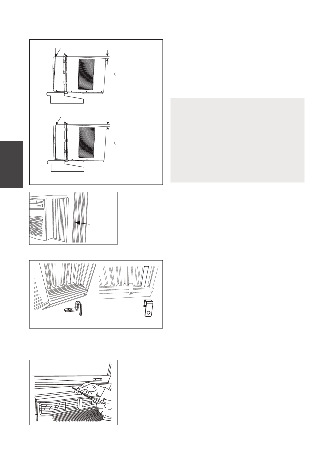
Instrucciones
de Instalción
4. INSTALA LOS PANELES DE ACORDEÓN
NOTA
Comprueba que el aire acondicionado
está inclinada hacia atrás casi H (Fig. 5)
(inclinado unos 3° a 4° desde el fondo
hacia la fuera) despúes de la instalación,
correcta, el condensado no debe
bajar desde el orificio de drenaje de
desbordamiento durante su uso normal,
corrige la pendiente de otro modo.
2.
Agarre firme al aire acondicionado, ponga
la unidad en la apertura de la ventana con
mucho cuidado para que el fondo del
marco del aire acondicionado está contra
el umbral de la ventana (Fig. 5). Acerque
la ventana detrás el carril superior de la
unidad con mucho cuidado..
3
. Extienda los paneles laterales en contra del marco de
la ventana (Fig. 6).
window
frame
Fig. 6
Fig. 5
Ventana de madera
DENTRO
FUERA
H
Ventana de vinil revestido
DENTRO
FUERA
H:Aproxima 3/4” a 1”
Mida desde el borde del gabinete
H
Fig. 7A Fig. 7B
Fig. 8A
5. AIRE ACONDICIONADO SEGURO
A.
Ponga el bloqueo del marco entre la
extensión de los marcos y el umbral de
la ventana como se muestra (Fig. 7A
para ventana de madera), (Fig. 7B para
ventana de vinil revestido).
Pase los tornillos de bloqueo 3/4“ (19 mm)
o 1/2” (12.7 mm) a través de la cerradura
de marco y en el alféizar.
NOTE: Para evitar la división del
umbral de la ventana, taladre un
agujero piloto de 1/8 ”(3 mm) antes
de conducer los tornillos.
B1:
Para ventanas de madera:
Pase los tornillos de bloqueo de 1/2” (12.7mm) entre los
agujeros del marco en la hoja de la ventana (Fig. 8A).
NOTE: Para evitar la división del umbral de la ventana,
taladre un agujero piloto de 1/8¨ (3mm) antes de
conducer los tornillos. Pase los tornillos de bloqueo
1/2” (12.7mm) a través de la cerradura de marco y en
el alféizar (Fig. 8B/8C).
Marco de
ventana
para 5K to K)
6
H:Aproxima
3/4” a 1”
para 5K to K)
6
Mida desde el borde del gabinete
62
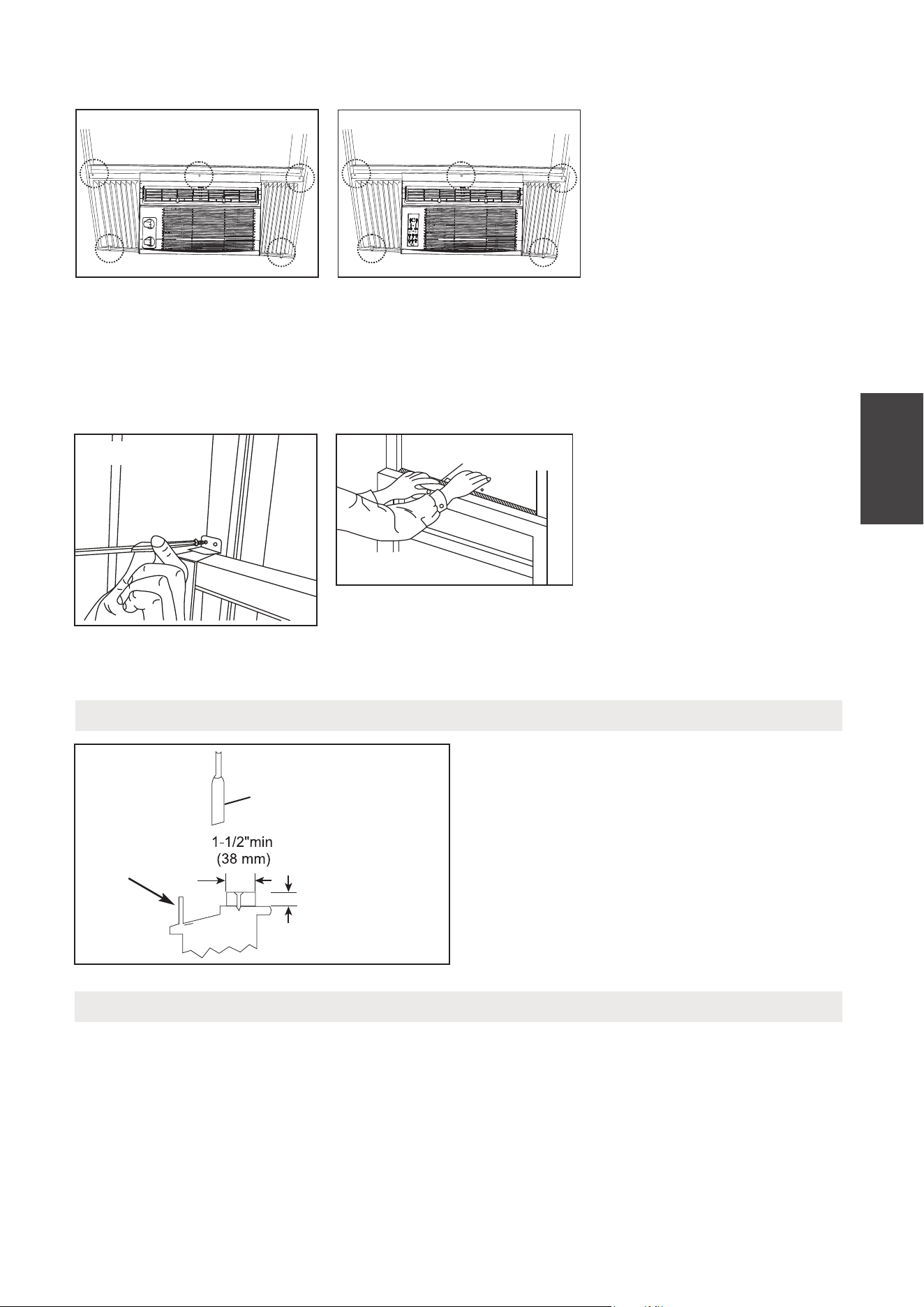
Instrucciones
de Instalción
Hoja
Ventana de
tormenta,
marco u otra
obstrucción.
Aborda el grueso
según necesidad
para un paso
adecuado a alzar
y un largo umbral
entero. Sujetalo con
clavos o tornillos.
Fig. 11
Si AC esté bloqueado por la Ventana de Tormenta
Añada maderas como se muestra en
Fig. 11, o elimine la ventana de tormenta
antes del aire acondicionado.
Si el marco de la Ventana de Tormenta
debe permanecer, asegúrese de que
los agujeros de drenaje o ranuras no se
calafatea o se pinta cerrada.
El agua de lluvia acumulada o condensada
debe puede drenar.
Eliminar AC de la Ventana
MAW05R/MAW06R Models
Fig. 8C
MAW05M Model
Fi 8
Fig. 8B
D. Corte el sello de espuma
de la hoja de la ventana y
pongala en el lugar entre
las hojas superiores y
inferiores. (Fig. 10).
Fig. 9
FOAM SEAL
Fig. 10
Sello de espuma
Fi 8
B2: Para ventanas de
vinilrevestido:
Pase los tornillos de
bloqueo de 1/2“ (12.7mm)
a través del cierre del
marco y en el marco de
la ventana (Fig. 8B/8C).
NOTE: Antes de conducir
los tornillos, utilice un
taladro para perforar 5
orificios a través de los
orificios del cierre del
marco y las extensiones
del marco en la hoja de la
ventana como se muestra
(Fig. 8B/8C).
C. Para instalar la baja
hoja inferior en un lugar
correcto, coloque bien el
bloqueo de la hoja ángulo
con tornillos de 3/4”
(19mm) o 1 /2” (12.7mm )
como se muestra (Fig. 9).
• Apaga el AC y separalo con el suministro de energía.
• Retire el sello de lahoja de ventana y desenrosque el bloqueo seguro de la hoja.
• Retire los tornillos instalados a través el marco y bloqueo del marco.
• Cierre (deslice) los paneles laterales entre los marcos.
• Garre firme al aire acondicionado, levanta la hoja y eliminala con cuidado.
• Tenga cuidado no derramar el agua restante mientras levante la unidad desde la
ventana. Guarda las partes CON el aire acondicionado.
63
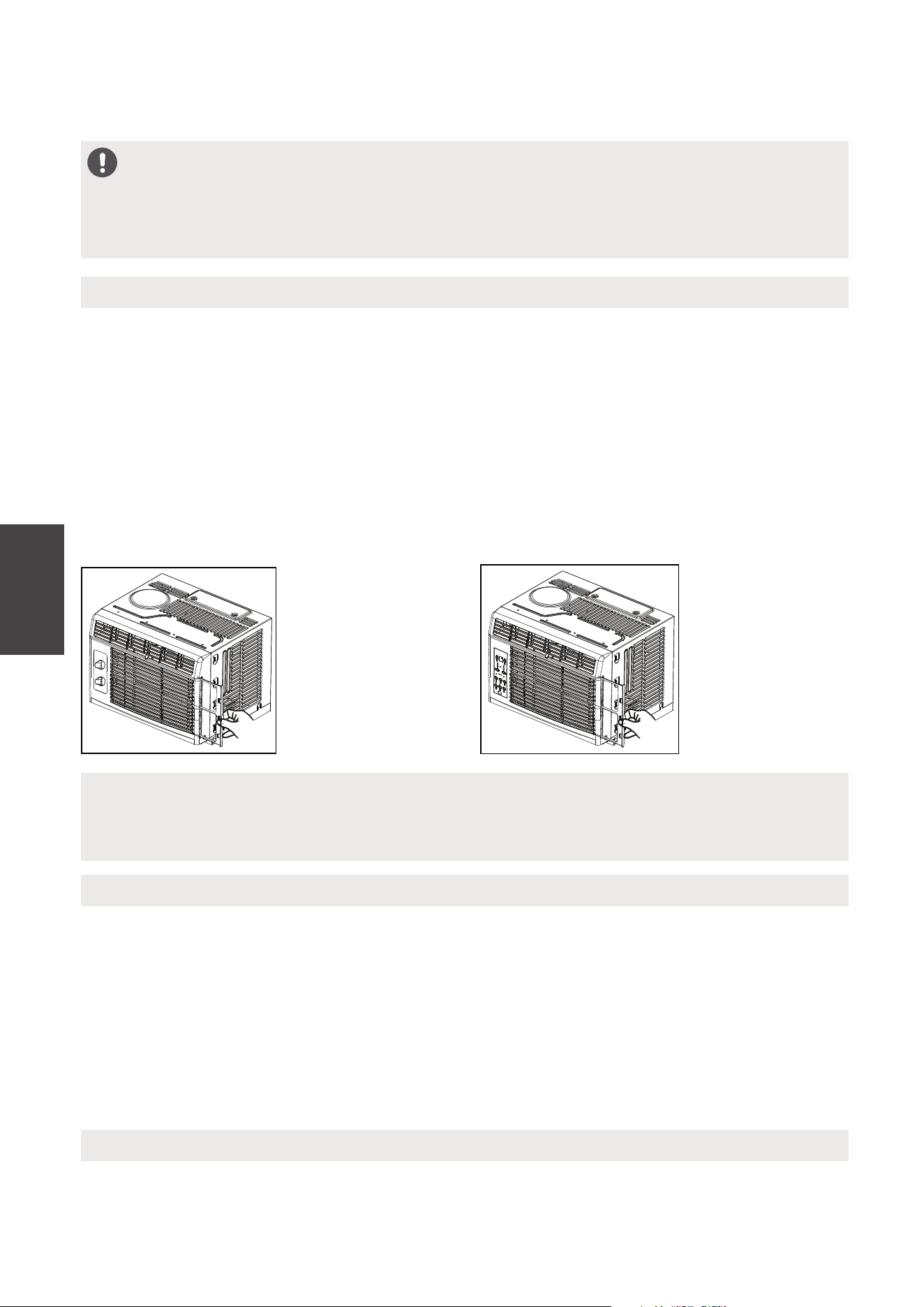
MANTENIMIENTO Y LIMPIEZA
Limpieza del Filtro de Aire
Limpieza del Gabinete
Almacenamiento en el Invierno
El filtro de aire debe ser revisado al menos una vez al mes para ver si es necesario
a limpiarlo. Las atrapadas partículas en el filtro podrán acumularse y causar una
acumulación de escarchas en las serpentinas de enfriamiento.
• Empuje la palanca de ventilación en la posición de Cerrada Vent (en su caso).
Abra el panel frontal.
• Tomar el filtro por el centro y tire hacia arriba y hacia fuera.
• Lave el filtro con un liquido detergente para lavar platos, en agua caliente.
Enjuague el filtro. Suavemente sacuda el exceso de agua del filtro. Asegúrese de
que el filtro está seco antes de volver. Si no, en lugar de lavar, podría aspirar el
filtro.
• Asegúrese de desconectar el AC para protegerlo de descarga eléctrica o
incendio. El gabinete y su frontera pueden ser limpiado por un paño libre de
aceite o un paño humedecido en agua caliente con liquido detergente para
limpiar platos.
Enjuaquelo bien y séquelo.
• Nunca use limpiadores abrasives, ceras ni pulimento en el frente del gabinete.
• Asegúrese de quitar el agua en el paño antes de limpiar los controles. El exceso
de agua dentro o alrededor del control podría causar daños al AC.
• Enchufe el aparato.
CAUTION
Limpie su aire acondicionado de vez en cuando para mantenerlo en buen aspecto.
Asegúrese de desenchufar la unidad antes de limpiarla para evitar el riesgo de
cuña o incendio.
NOTA
Nunca usar el agua más caliente que 104°F (40°C) a limpiar el filtro de aire.
Nunca trata de operar la unidad sin el filtro.
Si va a almacenar el aire acondicionado durante el invierno, eliminelo de la ventana con
mucho cuidado según las instrucciones de instalación. Cubralo con plástico o vuelvalo
en la caja.
Mantenimiento
y Limpieza
MAW05R/MAW06R Models MAW05M Model
64
Antes de llamar al servicio, revisa esta lista. Le podría ahorrar tiempo y molestia.
Esta lista incluye las ocurrencias communes, los cuales no son resultado por un
defecto del hechura o los materiales de la fábrica.
Problema Solución
El aire
acondicionado
no funciona
Enchufe de pared desconectado. Presione el enchufe con mucha
esfuerza en la toma de corriente.
Se disparó el disyuntor. Reinicie el disyuntor.
Compruebe si la luz del enchufe está encendida. Si está apagado,
presione el botón RESET.
Se apague. Enciendalo.
La unidad se apagó y luego se encendió rápidamente. Apague la
unidad y espere 3 minutos antes de reiniciar.
El aire de la
unidad no es
tan fría
La temperatura de la habitación está bajo 62°F (17°C). No empieza a
enfriar hasta la temperatura llega más que 62°F (17°C).
Los elementos del sensor de la temperatura detrás del filtro toca la
serpentina fría. Déjalo lejos de la serpentina fría.
Ajuste a una temperatura más baja.
El compresor para cuando cambia el modo. Espere 3 minutos despúes
de elegir el modo Frío.
Compruebe si hay posibles obstrucciones que bloqueen la entrada /
salida exterior. Elimine cualquier obstrucción.
El aire
acondicionado
enfria, pero la
habitación hace
calor – forma
hielo en la
serpentina fría
detrás el frente
decorativo
La temperatura fuera está bajo 64°F (18°C). Para descongelar la
serpentina, cambie al modo FAN ONLY.
El filtro de aire podría ser sucio. Limpie el filtro. Consulte la sección del
Mantenimiento y Limpieza. Para descongelarlo, cambie al modo
FAN ONLY.
El termostato ha ajustado demasiado frío durante su funcionamiento
de la noche. Para descongelarla, cambie al modo FAN ONLY. Despúes,
elige la una temperatura más alta.
El aire
acondicionado
enfria, pero la
habitación hace
mucho calor –
no forma hielo
en la serpentina
fría detrás
el frente
decorativo
Filtro de aire sucio o obstruido. Filtro limpio. Consulte la sección
Cuidado y limpieza. Para descongelar, establezca el modo SÓLO
VENTILADOR
Ha elegido una temperatura tan alta, elige una temperatura baja.
Ha puesto la rejillas direccionales incorrectamente. Ponga la rejilla en
un lugar con mejor distribución del aire.
La frontera de la unidad está cubierta con cortinas, persianas, muebles,
etc. –distribución de aire limitado. Elimine la obstrucción en la frontera
de la unidad.
Se escape el aire frío por las puertas, ventanas, rejillas, etc. Cierre la
puerta, ventana o rejilla.
Soluciones de
Problemas
SOLUCIONES DE PROBLEMAS
65
Soluciones de
Problemas
Problema Solución
El aire
acondicionado
se enciende y
apaga
rápidamente
Filtro de aire sucio - aire limitado. Limpie el filtro.
La temperatura fuera es demasiado alto. Elige la velocidad del
FAN a una opción más alto para traer más aires pasando por la
serpentina fría.
Compruebe si hay posibles obstrucciones que bloqueen la
entrada / salida exterior. Elimine cualquier obstrucción.
Hace ruido
cuando la
unidad enfria
El sonido del movimiento del aire es normal. Si hace tanto ruido,
cambie a una opción de FAN más baja.
La vibración de la ventana – mala instalación. Consulte las
instrucciones de instalación o consulte al instalador.
El agua que
gotea INTERIOR
cuando unidad
está enfriando
La instalación incorrecta. Inclina acondicionador de aire ligeramente
hacia el exterior para permitir el drenaje del agua. Consulte las
instrucciones de instalación - consulte con el instalador.
El agua que
gotea EXTERIOR
cuando unidad
está enfriando
Unidad eliminar gran cantidad de humedad del ambiente húmedo.
Esto es normal durante días excesivamente húmedos.
Teledetección
desactivación
Antes de
tiempo (algunos
modelos)
El control remoto no encuentra dentro del alcance. Coloque el
control
remoto dentro de 26.2 pies & 180°, radio de la parte
frontal de la unidad.
Sel de control remoto obstruido. Retire la obstrucción.
Habitación
demasiado fría
Ajuste la temperatura demasiado baja. Aumente la temperatura
de la unidad.
Ruido cuando la
unidad arranca.
51
Un sonido de "da-da" puede ocurrir durante treinta segundos
cuando la unidad se enciende debido al arranque del compresor.
Es normal.
La uniadad funciona en una habitación caliente recientemente.
Permitalo un plazo de tiempo adicional para eliminar los calores
guardados por las paredes, el techo, el suelo o los muebles.
66
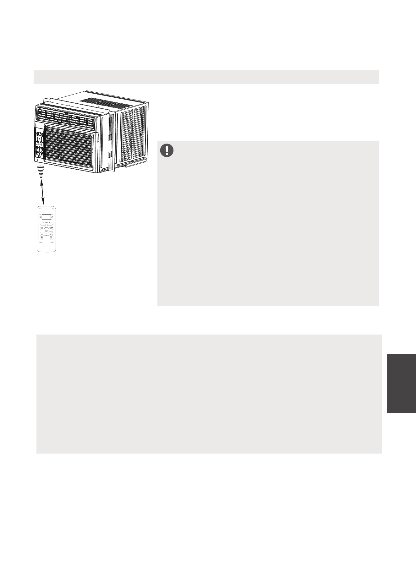
INSTRUCCIONES DEL CONTROL
REMOTO
Instrucciones
del Control
Remoto
UBICACIÓN DEL CONTROL REMOTO
Use el control remoto a una distancia de 26.2 pies
(8 metros) del acondicionador de aire, apuntándolo
hacia el receptor. La recepción se confirma con un
pitido.
26.2 ft (8 metros)
Manejo del Control Remoto
CAUTION
• El acondicionador de aire no funcionará si cortinas,
puertas u otros materiales bloquean las señales del
control remoto a la unidad.
• Evite que el líquido se derrame en el control
remoto. No exponga el control remoto a la luz
solar directa o al calor.
• Si el receptor de señal infrarroja de la unidad
interior está expuesto a la luz solar directa, es
posible que el acondicionador de aire no funcione
correctamente. Use cortinas para evitar que la luz
del sol caiga sobre el receptor.
• Si otros aparatos eléctricos reaccionan al control
remoto, mueva estos dispositivos o consulte a su
distribuidor local.
NOTES
• El diseño de los botones se basa en el modelo típico y puede variar ligeramente
del que usted compró.
• Todas las funciones descritas se realiza en la unidad. Si la unidad no tiene una
función, la unidad no responderá, si se presiona el botón correspondiente en el
control remoto.
• Cuando existan diferencias significativas entre las funciones u operaciones
implícitas en la ilustración del control remoto y las funciones reales descritas en
el MANUAL DEL USUARIO, prevalecerán las descripciones en el MANUAL DEL
USUARIO.
C-SENSE
67
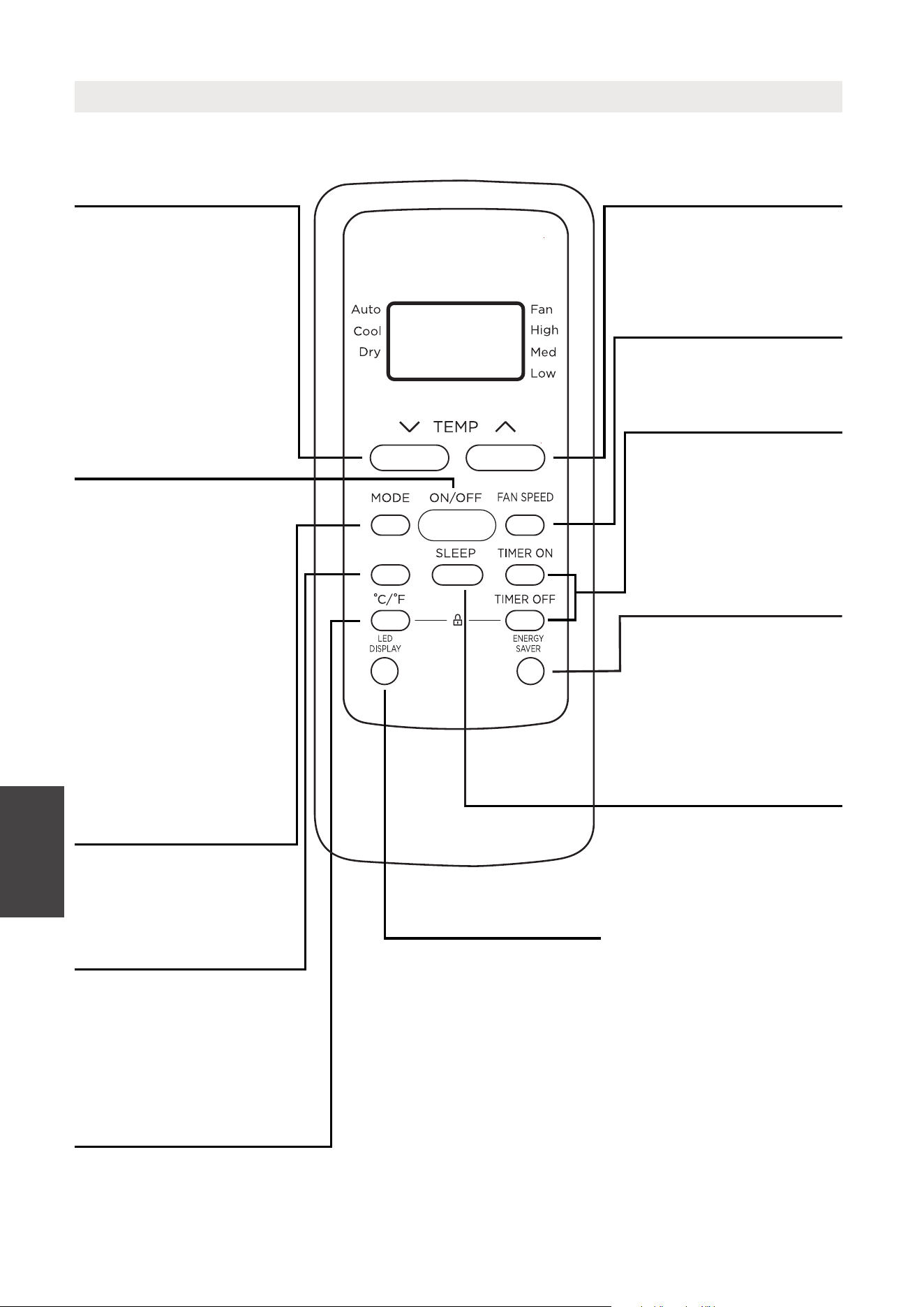
Botones de Función
Botón MODE
Presione este botón
para seleccionar el
modo de operación
deseado.
Botón TEMP UP
Presione este botón
para aumentar la
configuración de
temperatura interior.
Botón SPEED
Se usa para seleccionar
la velocidad del
ventilador deseada.
Botón SLEEP
Botón ENERGY SAVER
Presione este botón
para activar el modo
de ahorro de energía.
Presiónelo nuevamente
para detener la función.
Botón TEMP DOWN
Presione este botón
para disminuir la
configuración de
temperatura interior.
Botón TIMER
Presione este botón
para activar el
programa “Auto Start
”
o “Auto Stop”.
Botón ON/OFF
La operación se inicia
cuando se presiona
este botón y se detiene
cuando se presiona el
botón nuevamente.
Instrucciones
del Control
Remoto
Botón °C/°F
Cambia la pantalla de temperatura
entre Celsius y Fahrenheit.
Botón LED DISPLAY
Enciende / apaga la
pantalla LED de la
unidad.
C-SENSE
Botón COMFORTSENSE
Presione ComfortSense
botón para activar el modo
Sígueme, para optimizar la
temperatura a su alrededor
y garantizar la máxima
comodidad.
NOTE: Si la unidad tiene
la función AHORRO
DE ENERGÍA, iniciará
automáticamente la
función Ahorro de
energía en los modos
Frío, Deshumidificación
y Automático
(solo enfriamiento
automático y Ventilador
automático).
Presione este botón
para activar el modo
Sleep. Esta función
solo está disponible
en modo FRÍO
o AUTOMÁTICO
y mantendrá la
temperatura más
cómoda para usted
mientras ahorra
energía. Para obtener
más información,
consulte “Operación
en modo SLEEP”
en Pagina 46.
68
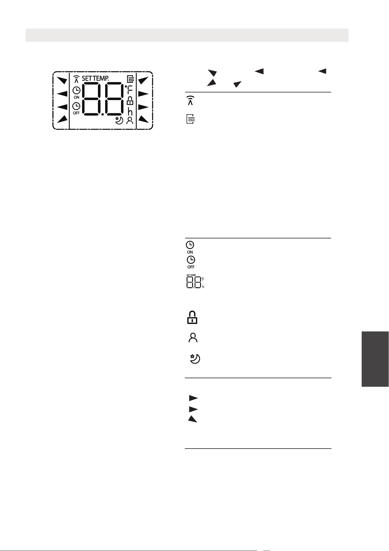
La información se muestra cuando se enciende el control remoto.
Todos los indicadores que se muestran en la figura tienen el propósito de una
presentación clara. Pero durante la operación de actaul, solo los signos de
función relativa se muestran en la ventana de visualización.
Indicadores De Pantalla Remota
Se muestra cuando se transmiten
los datos.
AUTO
COOL
DRY
HEAT
AUTO
HEAT
COOL
FAN
DRY
Pantalla de modo
FAN
HIGH
MED
LOW
Baja velocidad
Sin pantalla
Media velocidad
Alta velocidad
Velocidad automática
del ventilador
Se muestra cuando se ajusta la hora
TIMER ON
Se muestra cuando se ajusta la hora
TIMER OFF
Se indica que todos los ajustes actuales
son bloqueado
Muestra la temperatura establecida
o la temperatura ambiente, o el
tiempo en la configuración del
TEMPORIZADOR
HIGH
MED
LOW
Indicación de velocidad del ventilador
Aparece cuando la función SLEEP
está activado
Nota:
Instrucciones
del Control
Remoto
Se muestra cuando la función
ComfortSense activada (algunas
unidades)
Aparece cuando el control remoto
está habilitado y puede enviar una
señal a la unidad. Si desea apagar
el control remoto sin afectar la
unidad, apunte el control remoto
lejos de la unidad y presione el
botón ON / OFF.
Para encender el control remoto,
apunte el control remoto lejos de
la unidad y presione el botón
ON / OFF La unidad no recibirá
comandos del control remoto si
este indicador no está iluminado
69
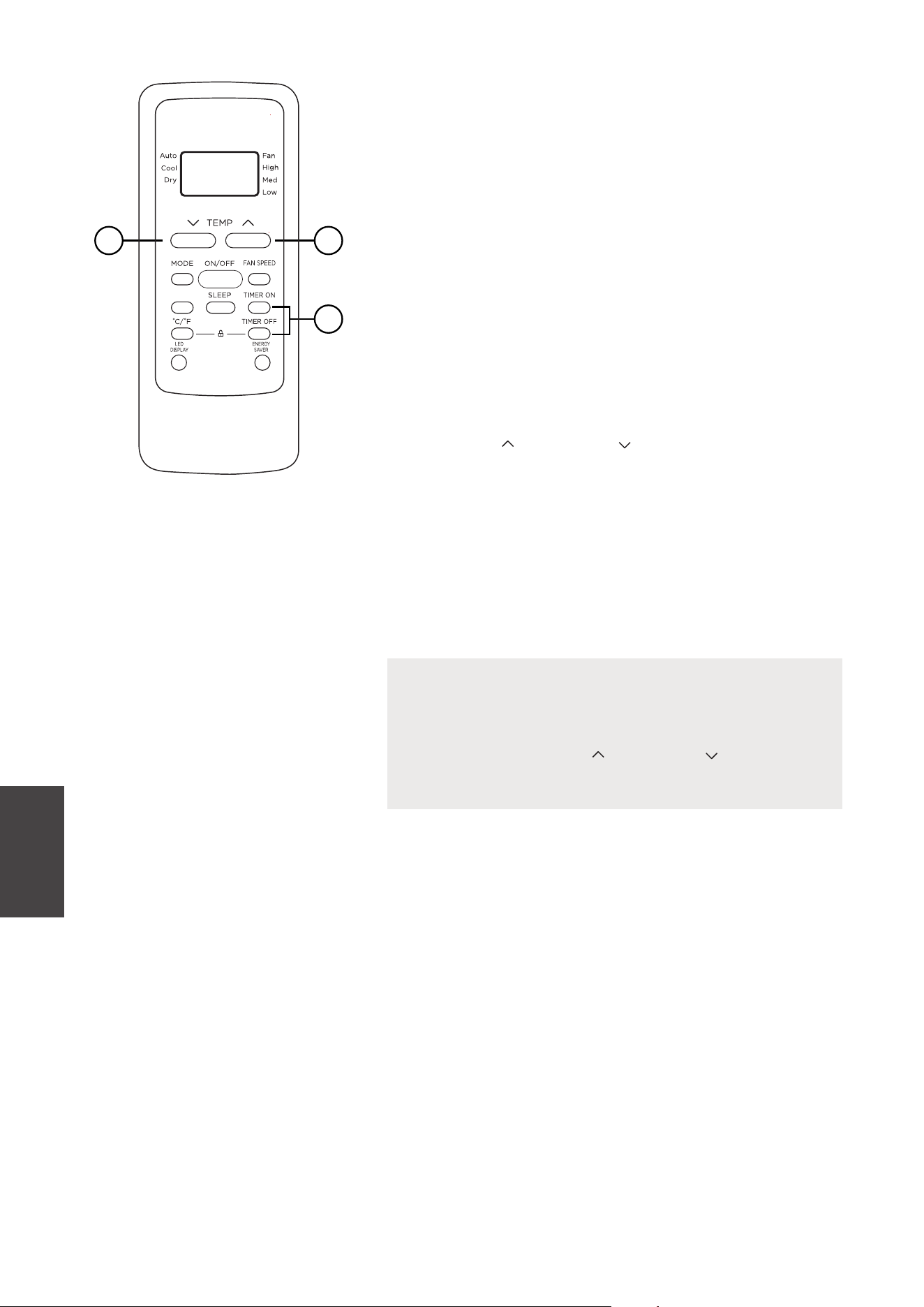
OPERACIÓN DEL TIMER
Presione el botón TIMER para iniciar el programa
de configuración Auto-start y Auto-stop de la
unidad.
Para establecer el tiempo de inicio / parada
automática.
1. Presione el botón TIMER, cuando el indicador
TIMER ON se muestre en el LED del
acondicionador de aire, indica que se inició el
programa de configuración Auto Start. Cuando
el indicador TIMER OFF se visualiza en el LED
del acondicionador de aire, indica que se inició
el programa de ajuste Auto Stop.
2. Presione o mantenga presionada la tecla TEMP
ARRIBA ( ) / ABAJO ( ) para cambiar la hora
automática. El control contará hacia atrás el
tiempo restante hasta el inicio / parada.
3. El tiempo seleccionado se registrará en
5 segundos y el acondicionador de aire
retrocederá automáticamente para mostrar la
configuración de temperatura anterior.
4. ENCENDER o APAGAR la unidad en cualquier
momento cancelará la función del Timer.
NOTES
1
22
Instrucciones
del Control
Remoto
C-SENSE
Para cancelar la configuración del TIMER, presione
el botón del TIMER y presione o mantenga
presionado TEMP UP ( ) / DOWN ( ) hasta que se
muestre 0 horas en el LED del aire acondicionado.
70
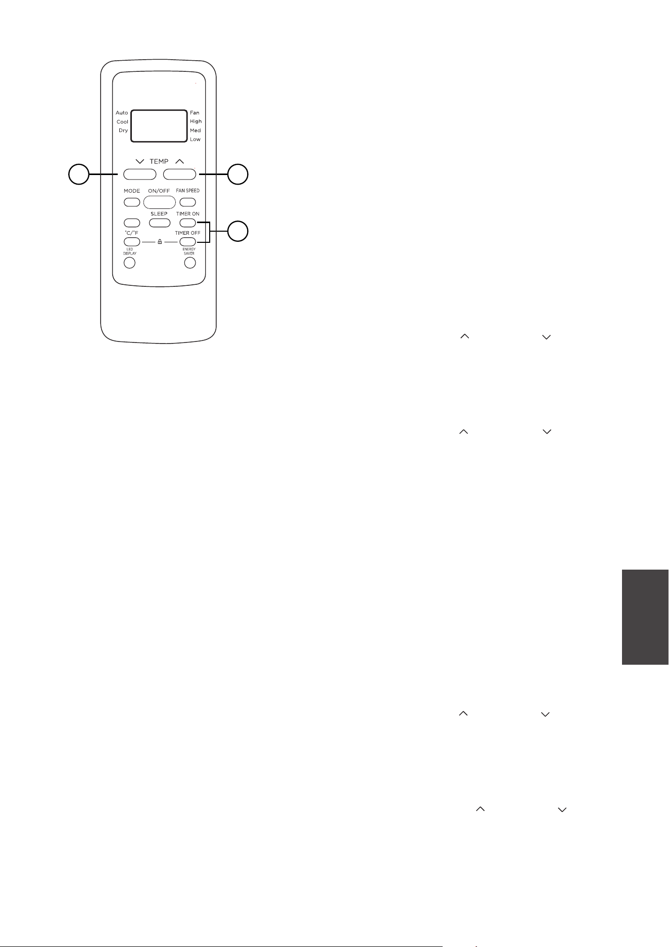
OPERACIÓN COMBINADA DEL TIMER
(Configuración del Timer ON y OFF simultáneamente)
AUTO STOP >AUTO START
(Encendido > Apagado > Iniciar la operación)
Esta función es útil cuando desea detener el aire
acondicionado después de acostarse y volver a
encenderlo por la mañana cuando se despierta o
cuando regresa a casa.
Ejemplo:
Para detener el aire acondicionado 2 horas
después de la configuración y volver a encenderlo
10 horas después de la configuración.
1. Presione el botón TIMER hasta que aparezca
el indicador TIMER OFF en el LED del
acondicionador de aire.
2. Use el botón TEMP UP ( ) / DOWN ( ) para
mostrar “2.0” en el LED del acondicionador de
aire.
3. Presione el botón TIMER nuevamente para
mostrar el TEMPORIZADOR APAGADO en el
LED de la unidad.
4. Use el botón TEMP UP ( ) / DOWN ( ) para
mostrar “10” en el LED de la unidad.
5. Espere 5 segundos hasta que aparezca la
visualización anterior en el LED.
AUTO START > AUTO STOP
(Apagado > Iniciar > Parar la operación)
Esta función es útil cuando desea encender el aire
acondicionado antes de despertarse y detenerlo
después de que sale de la casa.
Ejemplo:
Para e
ncender el aire acondicionado 5 horas
después de la configuración, y detenerlo 8 horas
después de la configuración.
1. Presione el botón TIMER hasta que se
muestre el indicador TIMER ON en el LED del
acondicionador de aire.
2. Use el botón TEMP UP ( ) / DOWN ( ) para
visualizar “5.0” en el LED del acondicionador de
aire.
3. Presione el botón TIMER nuevamente para
mostrar el TEMPORIZADOR APAGADO en el
LED de la unidad.
4. Utilice el botón TEMP UP ( ) / DOWN ( ) para
visualizar “8.0” en el LED de la unidad.
5.
Espere 5 segundos hasta que aparezca la
visualización anterior en el LED.
1
22
Instrucciones
del Control
Remoto
C-SENSE
71

NOTES
• El diseño del botón se basa en un modelo típico y puede variar ligeramente del real
que compró.
• Este dispositivo cumple con laparte 15 de las Reglas de la FCC. El funcionamiento
está sujeto a las dos condiciones siguientes: (1) Este dispositivo no puede causar
interferencias perjudiciales, y (2) este dispositivo debe aceptar cualquier
interferencia recibida, incluidas las interferencias que puedan causar un
funcionamiento no deseado.
• Este equipo ha sido probado y se encontró que cumple con los límites para un
dispositivo digital de Clase B, de acuerdo con la parte 15 de las Reglas de la FCC.
Estos límites están diseñados para proporcionar una protección razonable contra
interferencias dañinas en una instalación residencial. Este equipo genera, usa y
puede irradiar energía de radiofrecuencia y, si no se instala y usa de acuerdo con
las instrucciones, puede causar interferencia dañina a las comunicaciones de radio.
Sin embargo, no hay garantía de que la interferencia no ocurra en una instalación
en particular. Si este equipo causa interferencias perjudiciales para la recepción de
radio o televisión, lo cual puede determinarse encendiendo y apagando el equipo,
se recomienda al usuario que intente corregir la interferencia mediante una o más
de las siguientes medidas:
- Reorientar o reubicar la antena receptora.
- Aumente la separación entre el equipo y el receptor.
- Conecte el equipo a una toma de corriente en un circuito diferente al que está
conectado el receptor.
- Consulte con el distribuidor o un técnico experimentado en radio / TV para
obtener ayuda.
- Los cambios o modificaciones no aprobados por la parte responsable del
cumplimiento pueden anular la autoridad de los usuarios para operar el equipo.
Advertencia de batería:
No mezcle pilas nuevas y viejas y no mezcle pilas alcalinas, estándar
(carbono-zinc) o recargables (ni-cad, ni-mh, etc.)
ry
g
Declaración de conformidad del proveedor
47 CFR § 2.1077 Información sobre el cumplimiento
Identificador único:Midea brand,RG51G(1)/CEFU1-1,RG51G(1)/CEFU1
Parte responsable Información de contacto de los Estados Unidos
Midea America Corporation
300 Kimball Dr
Parsippany NJ
07054
Este dispositivo cumple con la Parte 15 de las Normas de la FCC. La operación
está sujeta a las siguientes dos condiciones: (1)Este dispositivo no puede
causar interferencias perjudiciales,y (2)este dispositivo debe aceptar
cualquier interferencia recibida, incluida la interferencia que pueda provocar
un funcionamiento no deseado.
Número de teléfono o información de contacto en Internet
:Midea.com/us
Declaración de cumplimiento de la FCC(productos sujetos a la Parte 15)
72
Instrucciones
del Control
Remoto

GARANTÍA Y POLITICA DE
DEVOLUCIÓN
Garantía de Acondicionador de Aire Midea
Su producto está protegido por esta garantía:
El servicio de garantía debe ser obtenido de Servicios al Consumidor de Midea o prestador de servicio autorizado Midea.
Garantía
Midea, a través de sus servicios autorizados, deberá:
• Pagar todos los costos de reparación o sustitución de las piezas de este aparato que demuestren que estén
defectuosas en materiales o hechura.
El consumidor será responsable de:
• Costos de diagnóstico, remoción, transporte y reinstalación requeridos por el servicio.
• Los costos de las llamadas de servicio que son el resultado de ítems indicados en el RESPONSABILIDADES
NORMALES DEL CONSUMIDOR **
Las piezas de reemplazo Midea se utilizar
án y garantizarán sólo por el período restante de la garantía original.
RESPONSABILIDADES NORMALES DEL CONSUMIDOR **
Esta garantía sólo se aplica a los productos de uso doméstico normal, y el consumidor es responsable de los ítems
listados siguientes:
1. Uso correcto del aparato de acuerdo con las instrucciones proporcionadas con el producto.
2. Mantenimiento rutinario y limpieza necesaria para mantener el buen estado de funcionamiento.
3. Instalación correcta por un profesional de servicio autorizado de acuerdo con las instrucciones proporcionadas
con el aparato y de acuerdo con todos los códigos locales de plomería, electricidad y/o gas.
4. Conexión adecuada a una fuente de alimentación conectada a tierra de suficiente voltaje, reemplazo de fusibles
quemados, reparación de conexiones aflojadas o defectos en el cableado doméstico.
5. Gastos para facilitar el acceso al aparato para el servicio.
6. Daños después de la instalación.
EXCLUSIONES
Esta garantía no cubre lo siguiente:
1) Fallo causado por daño a la unidad mientras en su posesión (diferente de los daños causados por defecto o mal
funcionamiento),
mediante su instalación inadecuada, o por uso irracional de la unidad, incluyendo, pero no limitado
a, la falta de mantenimiento razonable y necesario o de seguir las instalaciones escritas y el manual de instrucciones.
2) Daños causados por servicios realizados por personas que no sean prestadores de servicio autorizados Midea,
por uso de piezas que no sean piezas de repuesto Midea, obtenidos desde personas que no sean de servicios al
Consumidor Midea, o por causas externas como abuso, mal uso, suministro eléctrico inadecuado o casos fortuitos.
3) Si la unidad se pone a usos comerciales, de negocios, de alquiler u otro uso o aplicación que no sea para uso del
consumidor, no hacemos ninguna garantía, expresa o implícita, incluyendo, pero sin limitado a, cualquier garantía
implícita de comerciabilidad o idoneidad para un uso o propósito particular.
4) Productos sin números de serie originales o productos que tengan números de serie que se han alterado o no se
puede determinar fácilmente.
Nota: Algunos estados no permiten la exclusión o limitación de daños incidentales o consecuentes. Así que esta
limitación o exclusión no se aplique a usted.
SI USTED NECESITA SERVICIO
Conserve la factura de compra, la boleta de entrega o cualquier otro registro de pago apropiado.
La fecha en la factura estableció el período de garantía si requerir servicio.
Si el servicio se llev
a a cabo, es su mejor interés para obtener y conservar todos los recibos.
Esta garantía escrita le otorga derechos legales específicos. Usted también puede tener otros derechos que varían de
estado a estado.
El servicio bajo esta garantía debe ser obtenido mediante los siguientes pasos, en orden:
1) Póngase en contacto con Servicios al Consumidor Midea o un prestador de servicio autorizado Midea a 1 866 646 4332.
2) Si hay una pregunta sobre dónde obtener servicio, póngase en contacto con nuestro departamento de relaciones
de consumidor.
ntía
Garantía
•
•
Un año completo de garantía a partir de la fecha de entrega o de la fecha de compra, lo que sea posterior.
La fecha de entrega establece el período de garantía, en caso de que se requiera servicio.
73

Preguntas sobre la instalación o el funcionamiento
producto Midea?
Sitodavía necesita asistencia, por favor llame al Atención
al Cliente en 1-866-646-4332.
Tenga disponible su recibo de compra número de serie
y el múmero de modelo del producto cuando llame.
El producto podrá devolverse dentro de lo 30 días de
la compra con el recibo. Luego de los 30 días, el producto
está cubierto por la garantía limitada. Consulte la sección
de garantía en el manual de usuario para información.
Política de devolución
guarde su
comprobante
POLITICA DE DEVOLUCION
30
74


16120300A36352
20250729
2025
MAWOPP