
Field Assembly Guide
to Prep, Position, & Fill
Commercial
Systems
1-3” Top Mount Systems
aosmith.com/commercialwatertreatment

Pre-Installation
Preparing and Positioning ............................................5
Filling. . . . . . . . . . . . . . . . . . . . . . . . . . . . . . . . . . . . . . . . . . . . . . . . . . . . . . . . . . . . . . 6
Gravel and Media Quantity Sheet ......................................7
Table of Contents
Inspection for Damage....................................................3
Operating Pressure and Temperature.........................................3
Parts Breakdown......................................................... 3
3
IMPORTANT
Prior to Beginning Assembly and Filling:
Inspect all components and tanks for damage during shipping. Reference the parts breakdown images for your distribuon
system on pages 3 and 4 and check o the components below to conrm they are present. Reference the gravel and media
quanes on page 7 and conrm the correct type and quanty is present.
Thoroughly review the instrucons within this guide to understand and become familiar with the placement, eld assembly,
and media loading process of a top mount system.
All commercial top mount systems require assembly and lling in the eld.
Failure to understand and comply with the instrucons within this guide may result in failure of the unit,
causing signicant damage to the unit and its surroundings.
Operang Pressure and Temperature
The normal operang pressure is 30 – 85 psi.
• If the i�coming water pressure is higher than 85 psi, a regulang valve must be installed.
• If the incoming water pressure is lower than 30 psi, a regulated booster pump must be installed.
The normal operang temperature is 40 – 100° Fahrenheit.
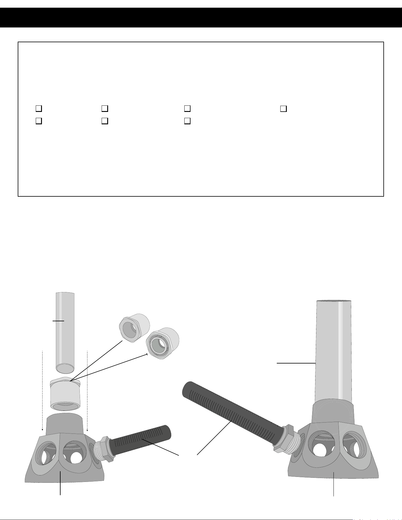
Parts Breakdown
For 1” – 2” valve systems:
Lateral Hub
Distributor Tube
Laterals (x8)
Chrome QC Top Flange
Black Threaded Top Flange
Black Boom Tank Plate
Flange Bolt Kit (CH4750)
Parts Breakdown
For 1” -2” valve systems
PVC Distributor
Tube
1” Bushing
Used on 1
1/4”
Systems
3/4” Bushing
Used on 1”
Systems
1
1/2”
- 2” systems do not use a bushing
Lateral
Lateral Hub
Lateral Hub
1.5” PVC
Distributor Tube
Table of Contents
Pre-Installation
4
PVC Distributor Tube
Distributor tube normally comes pre-in-
stalled on cap of lateral hub
Lateral Hub Cap
Lateral Hub Base
Lateral Hub
points
Lateral
Parts Breakdown
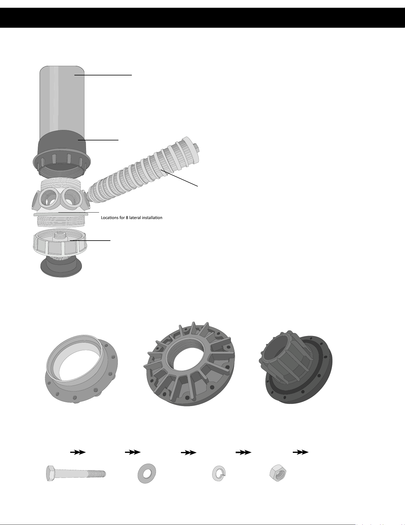
For 3” valve systems or tanks larger than 24” in diameter:
Top and Boom Flanges
It is crical to ensure that anges are installed and the plate bolts are ghtened adequately prior to lling. Failure
will lead to crical leak issues which may require emptying media to re-install.
Flange Bolt Kit
Flange bolts are installed in the order shown below:
1. Flange Bolt 2. Flat Washer 3. Flange/Plate 4. Flat Washer 5. Lock Washer 6. Flange Nut
Chrome Top Flange Adapter Black Boom Tank Plate
Black Threaded Top Flange
Flange Nut (x12)Flange Flat Washer (x24) Flange Lock Washer (x12)Flange Bolt (x12)
Chrome Top Flange Adapter
Black Threaded Top Flange
Flange Nut (x12)Flange Flat Washer (x24) Flange Lock Washer (x12)Flange Bolt (x12)
Pre-Installation
5
Preparing and Posioning the Unit
1. Select a posion near a drain that has adequate carrying capacity to handle the unit’s backwash ow rate. Refer to the system’s
specicaon sheet for the backwash ow rate.
2. Follow the Distribuon Installaon instrucons in the illustraons below before proceeding to step 3.
Place box or cardboard under tank to avoid
scratches from rough ground surfaces.
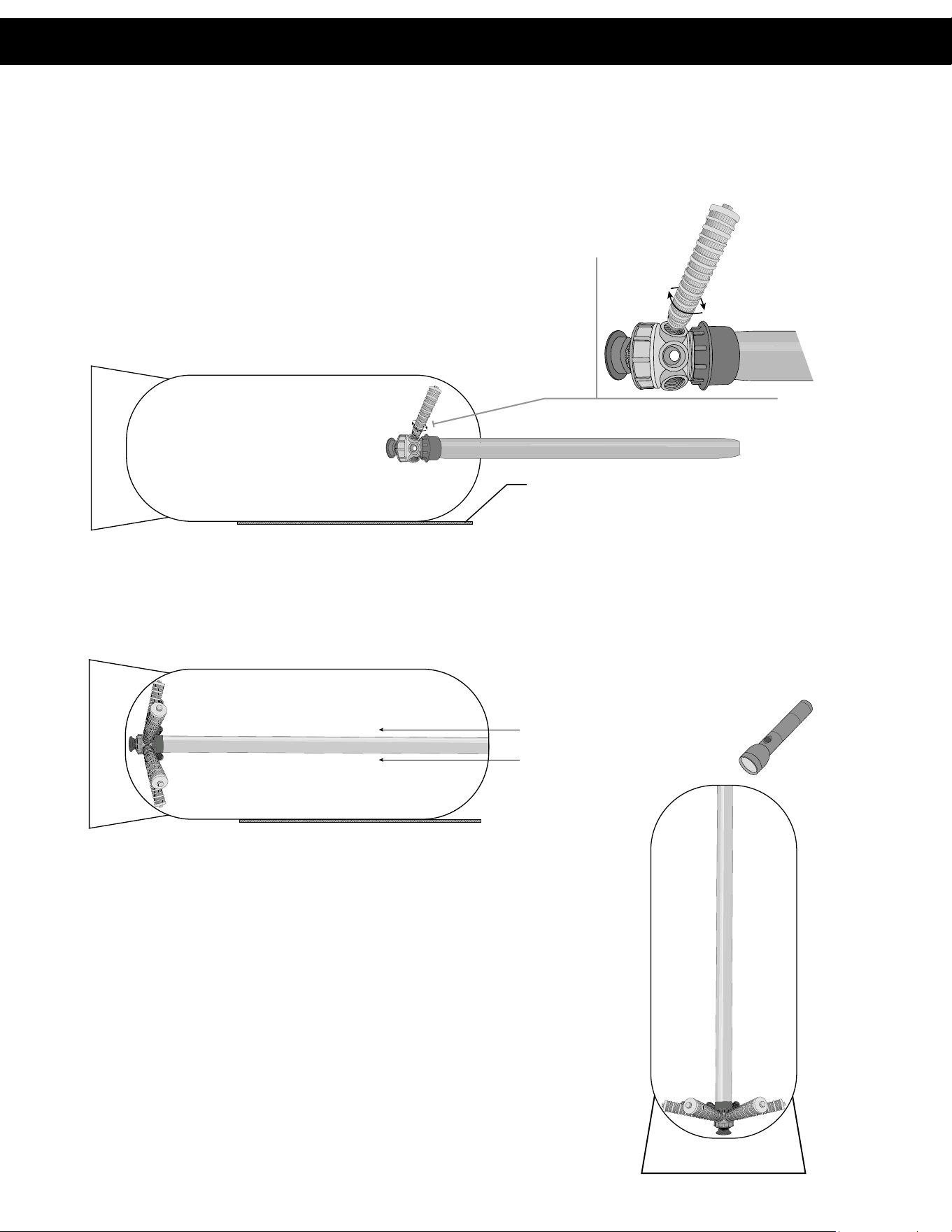
Top Mount Distribuon Installaon Instrucons:
A. Carefully place mineral tank on its side. With the distributor hub inside
the tank, screw the lateral clockwise into one of the eight hub slots.
Connue threading laterals into hubs unl hand ght. Repeat process
unl all eight laterals are installed.
Do not over-ghten or use thread compound on laterals.
B. Slide the distribuon system into the tank slowly to avoid shock.
Connue unl the hub rests against the boom of the tank.
C. Slowly raise the unit upright near the nal installaon locaon. Using
a ashlight, re-inspect the distribuon hub and laterals for potenal
damage incurred from raising the tank.
The distribuon system is now installed. Connue with step 3 on the
following page.
Preparing & Positioning
6
Preparing and Posioning the Unit (connued)
3. Place the tank on a level and rm foundaon (preferably concrete). Verify that the riser tube is ush with the top of
the tank.
Tip: It is recommended to spin the control valve on the tank to verify that the valve and tank orientaon are correct.
4. Determine and mark the locaon of the brine maker (for soeners only). It is not necessary to place it in this locaon yet.
5. For installers: Check, Inial, and Date the following boxes prior to proceeding to the lling instrucons.
Filling Instrucons
Note: DO NOT proceed with lling instrucons unl unit is in its nal posion.
1. If installed, remove the valve from the top of the tank.
2. Verify that the riser tube is ush with the top of the tank. Re-inspect the distribuon system with a ashlight and conrm th com-
ponents are sll in place and undamaged.
3. Cover the opening of the distributor tube with the provided rubber cap. This prevents gravel or media from entering the
distributor assembly during the lling process.
4. Verify that the correct type and amount of gravel for the unit being installed is present. The correct type and amount can be
conrmed on the table on page 7.
NOTE: If the correct type and amount of gravel is not on site, do not load the tank.
Contact the distributor or factory for correcons.
TIP: On tanks 24” and larger, ll tank 1/4 full with water to aid in gravel lling.
5. Prepare to add mineral to the tank. Verify that the correct type and amount of mineral for the soener or lter that is being
installed is on site. The correct type and amount can be conrmed on the table on page 6.
NOTE: If the correct type and amount of mineral is not on site, do not load the tank.
Contact the distributor or factory for correcons.
6. Slowly pour in the correct amount of mineral.
7. If possible, ll the tank to the top with water at this me.
8. Remove the rubber cover from the top of the riser pipe. Clean the riser pipe, tank threads and the exterior of the tank of any
excess media or gravel debris.
9. Lubricate the distributor O-ring seal and tank ring seal using a non-aerosol, food grade silicone lubricant.
10. Align the riser pipe into the control valve, taking care to seat the riser pipe against the internal O-ring. With the distributor tube
in place, push the control valve down unl it pushes against the tank threads.
11. Turn the control valve clockwise, taking cauon to not cross-thread, unl the gasket seats and is ght.
12. Verify that the orientaon of the control valve is correct before installing the plumbing.
Before connuing, I have ensured that: Inials Date
The distribuon system has been successfully installed and inspected
for damage.
The unit is located in its nal posion.
*It is not recommended to reposion tanks aer lling!
The plumbing layout is correct.
Positioning & Filling
7
Factory Inspecon: __________
Inials From Assembly Team Leader: __________
Gravel Type and Quanty
Add __________ lbs. of _____________ Gravel Underbedding
Add __________ lbs. of _____________ Gravel Underbedding
Media Type and Quanty
Add __________ Cu. Ft. of _____________ Media
Add __________ Cu. Ft. of _____________ Media
Add __________ Cu. Ft. of _____________ Media
Add __________ Cu. Ft. of _____________ Media
Amount and Type of Media:
Inspecon Sign-o (Please Inial):
Note: The instrucons and illustraons in this guide are only intended to be used as general guidelines for assembling a
Commercial Top Mount System in the eld. Units and assemblies will dier from those detailed in this guide.
Contact the manufacturer for more informaon.
Gravel & Media Quantity

© 2018 A. O. Smith, Inc. All rights reserved.
REV0326 - 100403335 - 2000857089
1900 Prospect Court • Appleton, WI 54914
Phone: 920-739-9401 • Fax: 920-739-9406