Model: 310115
READ AND SAVE THESE INSTRUCTIONS
1
1. CAUTION - To reduce the risk of electric
shock, insure electricity has been
turned off at the circuit breaker or fuse
box before beginning.
2. WARNING: All wiring must be in
accordance with the National Electrical
Code and local electrical codes.
Electrical installation should be
performed by a qualified licensed
electrician.
3. WARNING: To reduce the risk of
electric shock, this fan must be installed
with a general-use, isolating wall
control/switch.
4. WARNING: Not Suitable for use with
solid-state speed controls.
5. WARNING: To reduce the risk of fire,
electric shock, or personal injury, mount
to outlet box marked "acceptable for
fan support of 15.8 kg (35 lbs.) or less"
and use mounting screws provided with
the outlet box. Most outlet boxes
commonly used for the support of light
fixtures are not acceptable for fan
support and may need to be replaced.
Due to the complexity of the installation
of this fan, a qualified licensed
electrician is strongly recommended.
6. The outlet box and support structure
must be securely mounted and capable
of reliably supporting a minimum of 50
pounds. Use only ETL Listed outlet
boxes marked "FOR FAN SUPPORT".
7. The fan must be mounted with a
minimum of 7 feet clearance from the
trailing edge of the blades to the floor.
8. To operate the reverse function on this
fan, press the reverse button while the fan
is running.
9. WARNING: Use only with light kit marked
"Suitable for Use in Wet Locations".
10. Avoid placing objects in the path of the
blades.
11. To avoid personal injury or damage to the
fan and other items, be cautious when
working around or cleaning the fan.
12. Do not use water or detergents when
cleaning the fan or fan blades. A dry dust
cloth or lightly dampened cloth will be
suitable for most cleaning.
13. After making electrical connections,
spliced conductors should be turned
upward and pushed carefully up into
outlet box. The wires should be spread
apart with the grounded conductor and
the equipment- grounding conductor on
one side of the outlet box and the
ungrounded conductor on the other side
of the outlet box.
14. Electrical diagrams are reference only.
Light kits that are not packed with the fan
must be ETL Listed and marked suitable
for use with the model fan you are
installing. Switches must be ETL General
Use Switches. Refer to the Instructions
packaged with the light kits and switches
for proper assembly.
WARNING
TO REDUCE THE RISK OF FIRE, ELECTRIC
SHOCK OR PERSONAL INJURY, MOUNT
FAN TO OUTLET BOX MARKED
"ACCEPTABLE FOR FAN SUPPORT".
WARNING
TO REDUCE THE RISK OF PERSONAL
INJURY, DO NOT BEND THE BLADE
BRACKETS (ALSO REFERRED TO AS
FLANGES) DURING ASSEMBLY OR AFTER
INSTALLATION. DO NOT INSERT OBJECTS
IN THE PATH OF THE BLADES.
1. SAFETY RULES
The net weight of this fan is:
N.W.: 14.0 kgs (30.86 LBS),
G.W.: 15.0 kgs (33.06 LBS).
2
80” Lehr
TM
1. SAFETY RULES (continued)
• INGESTION HAZARD: This product contains a button cell or coin battery.
• DEATH or serious injury can occur if ingested.
• A swallowed button cell or coin battery can cause Internal Chemical Burns in as little as 2 hours.
• KEEP new and used batteries OUT OF REACH of CHILDREN.
• Seek immediate medical attention if a battery is suspected to be swallowed or inserted inside any
part of the body.
• Remove and immediately recycle or dispose of used batteries according to local regulations and keep
away from children. Do NOT dispose of batteries in household trash or incinerate.
• Even used batteries may cause severe injury or death.
• Call a local poison control center for treatment information.
• Battery Type: CR2032 and Nominal Battery Voltage: 3V.
• Non-rechargeable batteries are not to be recharged.
• Do not force discharge, recharge, disassemble, heat above 40º C or incinerate. Doing so may result in
injury due to venting, leakage or explosion resulting in chemical burns.
• Ensure the batteries are installed correctly according to polarity (+ and -).
•
carbon-zinc, or rechargeable batteries.
• Remove and immediately recycle or dispose of batteries from equipment not used for an extended
period of time according to local regulations.
• Always completely secure the battery compartment. If the battery compartment does not close
securely, stop using the product, remove the batteries, and keep them away from children.
WARNING
1. NORMAS DE SEGURIDAD (continuación)
• RISQUE D’INGESTION : Ce produit contient une pile bouton.
• La MORT ou des blessures graves peuvent survenir en cas d’ingestion.
• Une pile bouton avalée peut provoquer des brûlures chimiques internes en 2 heures seulement.
• GARDER les piles neuves et usagées HORS DE LA PORTÉE DES ENFANTS.
• Consultez immédiatement un médecin si vous soupçonnez qu’une pile a été avalée ou insérée dans
une partie du corps.
• Retirer et recycler ou jeter immédiatement les piles usagées conformément aux réglementations
locales et les garder hors de portée des enfants. NE PAS jeter les piles avec les ordures ménagères ni
les incinérer.
• Même les piles usagées peuvent provoquer des blessures graves, voire la mort.
• Appeler un centre antipoison local pour obtenir des informations sur le traitement.
• Type de pile : CR2032 et tension nominale de la pile : 3 V.
• Ne pas recharger les piles non rechargeables.
• Ne pas forcer la décharg
e, la rec
harge, le démontage, la chaleur au-dessus de 40°C ni l’incinération.
Le non-respect de ces consignes peut entraîner des blessures dues à une ventilation, une fuite ou une
explosion entraînant des brûlures chimiques.
• S’assurer que les piles sont installées correctement en fonction de la polarité (+ et -).
• Ne pas mélanger des piles anciennes avec des piles neuves, des marques ou des types de piles, tels
que des piles alcalines, carbone-zinc ou rechargeables.
• Retirer et recycler ou jeter immédiatement les piles des équipements non utilisés pendant une période
prolongée, conformément aux réglementations locales.
• Toujours bien sécuriser le compartiment des piles. Si le compartiment des piles ne se ferme pas
correctement, ne plus utiliser le produit, retirer les piles et les garder hors de portée des enfants.
AVERTISSEMENT
80” Lehr
TM
1. RÈGLES DE SÉCURITÉ (suite)
• PELIGRO DE INGESTIÓN: Este producto contiene una pila tipo botón o tipo moneda.
• En caso de ingestión puede producirse la MUERTE o lesiones graves.
• La ingestión de una pila tipo botón o tipo moneda puede provocar Quemaduras Químicas Internas en
tan sólo 2 horas.
• MANTENGA las pilas nuevas y usadas FUERA DEL ALCANCE DE LOS NIÑOS.
• Acuda inmediatamente a un médico si sospecha que se ha tragado o introducido una pila en
cualquier parte del cuerpo.
• Retire las pilas usadas y recíclelas o deséchelas inmediatamente de acuerdo con la reglamentación
local y manténgalas fuera del alcance de los niños. NO deseche las pilas en la basura de su casa ni las
incinere.
• Incluso las pilas usadas pueden causar lesiones graves o la muerte.
• Llame a un centro de control de intoxicaciones local para obtener información sobre el tratamiento.
• Tipo de pila: CR2032 y Voltaje nominal de la pila: 3V.
• Las pilas no recar
gables no deben recargarse.
•
No fuerce la descarga, recargue, desarme, caliente por encima de 40° C ni incinere. De lo contrario,
podrían producirse lesiones debido a venteo, fugas o explosiones que provoquen quemaduras
químicas.
• Asegúrese de que las pilas estén instaladas correctamente según la polaridad (+ y -).
• No mezcle pilas nuevas y usadas, ni pilas de marcas o tipos diferentes, como pilas alcalinas, de
carbono-zinc o recargables.
• Retire e inmediatamente recicle o deseche las pilas de los equipos que no haya utilizado durante un
período prolongado de tiempo de acuerdo con las regulaciones locales.
• Asegure siempre completamente el compartimento de las pilas. Si el compartimento de las pilas no
cierra bien, deje de utilizar el producto, retire las pilas y manténgalas fuera del alcance de los niños.
ADVERTENCIA
3
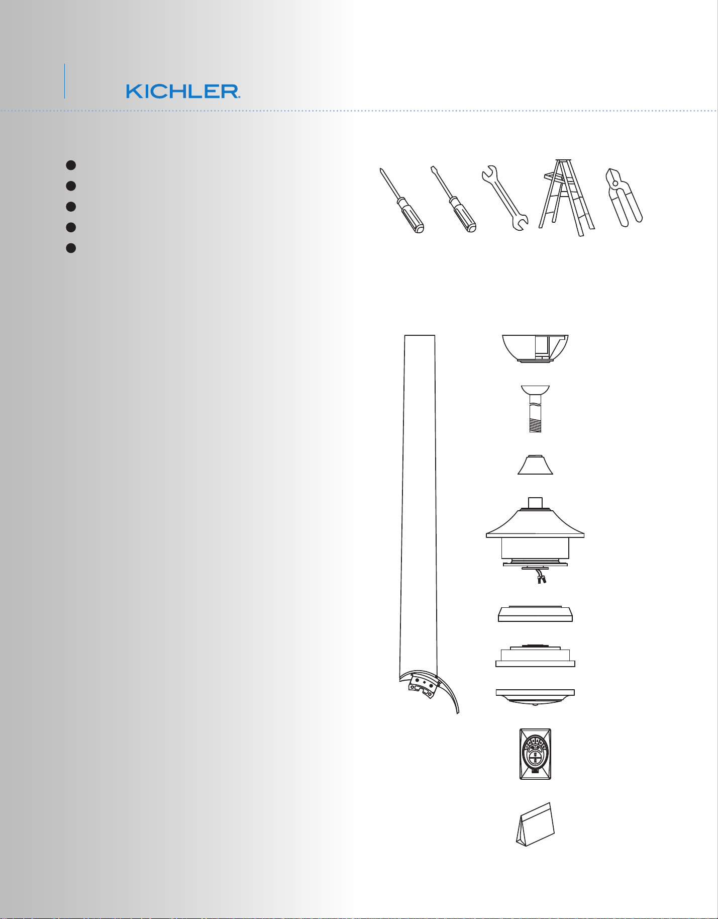
Philips screw driver
Blade screw driver
11 mm wrench
Step ladder
Wire cutters
2. TOOLS AND MATERIALS REQUIRED
3. PACKAGE CONTENTS
Unpack your fan and check the contents. You
should have the following items:
a. Fan blade assembly (7)
b. Canopy & Ceiling mounting bracket
c. Ball/downrod assembly
d. Coupling cover
e. Fan motor assembly
f. Blade support plate
g. Mounting plate
h. Motor bottom housing
i. CoolTouch™ Control System
j. Part bag contents
1) Mounting hardware:
wood screws (2), flat washers (2),
star washers (2), wire nuts (3),
screws (2)
2) Blade brackets hardware:
screws (2)
4) Safety cable hardware:
wood screw, spring washer, flat washer
5) Balance Kit
a
b
c
d
e
f
g
h
i
j
4
80” Lehr
TM
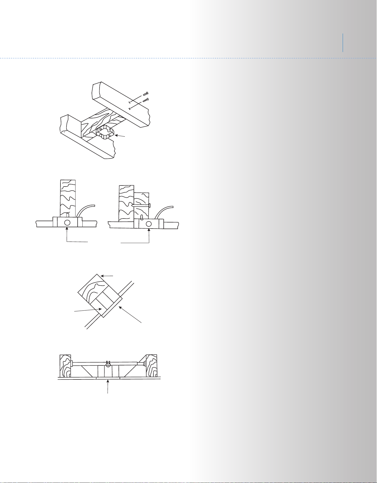
Outlet box
Fig. 4
4. MOUNTING OPTIONS
Provide strong
support
Recessed
outlet box
Ceiling
mounting
plate
Outlet box
Fig. 1
Fig. 3
Outlet box
Fig. 2
ANGLED CEILING
MAXIMUM 20
°
ANGLE
If there isn't an existing ETL listed mounting
box, then read the following instructions.
Disconnect the power by removing fuses or
turning off circuit breakers.
Secure the outlet box directly to the building
structure. Use appropriate fasteners and
building materials. The outlet box and its
support must be able to fully support the
moving weight of the fan (at least 50 lbs). Do
not use plastic outlet boxes.
Figures 1, 2 and 3 are examples of different
ways to mount the outlet box.
NOTE: If you are installing the ceiling fan on a
sloped (vaulted) ceiling, you may need a
longer downrod to maintain proper clearance
between the tip of the blade and the ceiling.
A minimum clearance of 12" is suggested for
optimal operation.
NOTE: Depending on the location you have
selected for installation, you may need to
purchase and install a "Joist Hanger" for the
support of the outlet box. Make sure the joist
hanger you purchase has been designed for
use with ceiling fans. (Fig. 4)
5
Fig. 6
Fig. 7
Fig. 8
Mounting screws
(supplied with
electrical box)
Hook
Ceiling
mounting
bracket
CUL Listed
electrial
box
120V Wires
Washers
REMEMBER to turn off the power before you
begin.
To properly install your ceiling fan, follow the
steps below.
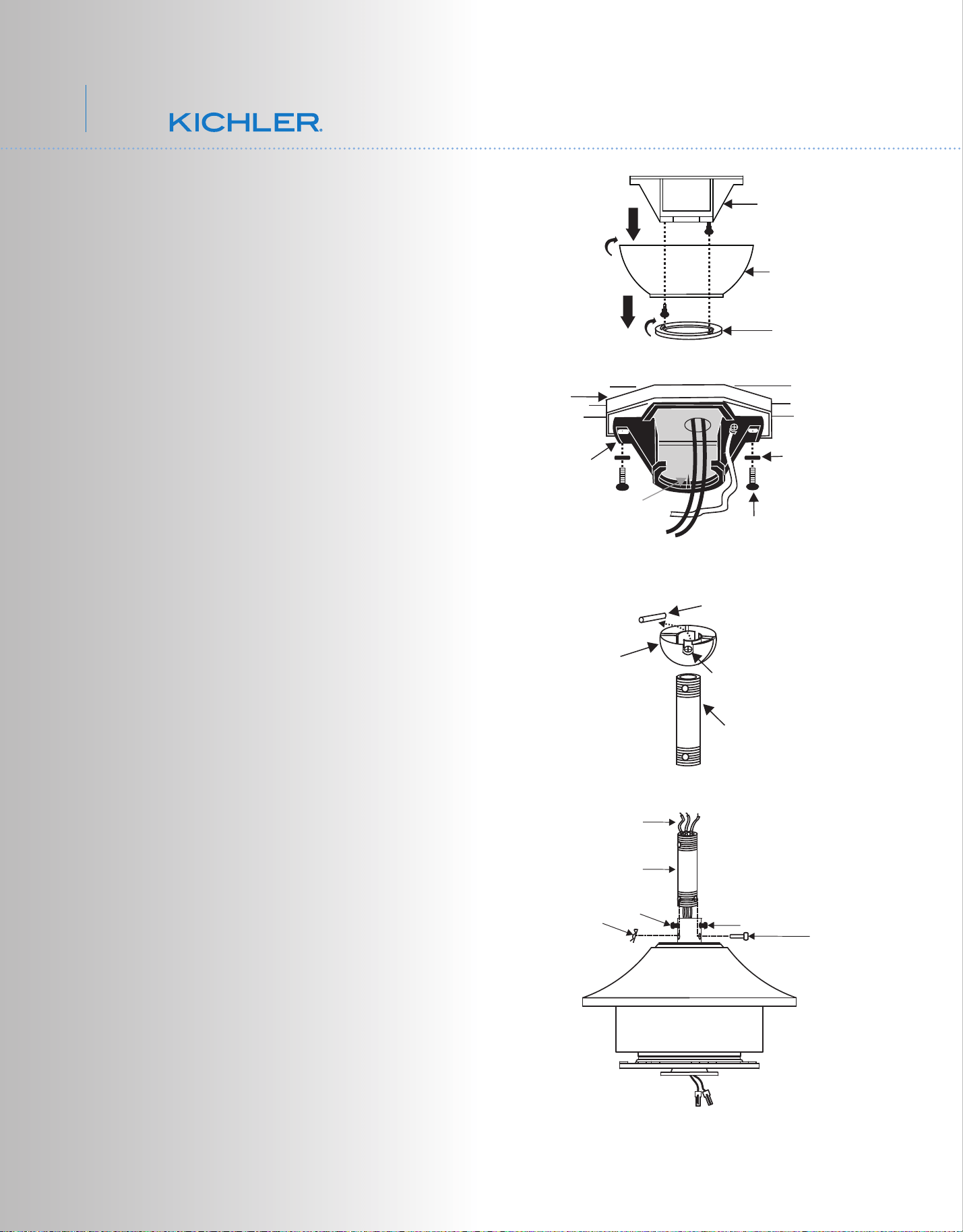
Step 1. Remove the decorative canopy
bottom cover from the canopy by turning the
cover counter clockwise. (Fig. 5)
Step 2. Remove the ceiling mounting bracket
from the canopy by removing (and save one
of the two screws. Loosen the remaining
screw by a half turn. (Fig. 5)
Step 3. Pass the 120 volt supply wires from
the ceiling outlet box through the center of the
ceiling mounting bracket. (Fig.6)
Step 4. Attach the ceiling mounting bracket to
the outlet box using the screws and washers
included with the outlet box. (Fig. 6)
Step 5. Remove the hanger ball from the
downrod assembly by loosening the set
screw, removing the cross pin and
unscrewing the ball off the rod. (Fig.7)
Step 6. Loosen the two set screws and
remove the hitch pin and retaining clip from
the coupling on top of the motor assembly.
(Fig. 8)
Step 7. Carefully feed the electrical lead wires
from the fan up through the downrod. Thread
the downrod into the coupling until the Hitch
pin holes are aligned.
Next, replace the hitch pin and retaining clip.
Tighten both set screws. (Fig. 8)
Downrod
Cross pin
Hanger
ball
Set screw
Supply wires
Downrod
Hitch pin
Retaining clip
Set screws
Set screws
Fig. 5
Hanger bracket
Ceiling
canopy
Canopy
cover
5. HANGING THE FAN
6
80” Lehr
TM
Fig. 9
Fig. 10
Registration slot
Downrod
Canopy
Canopy cover
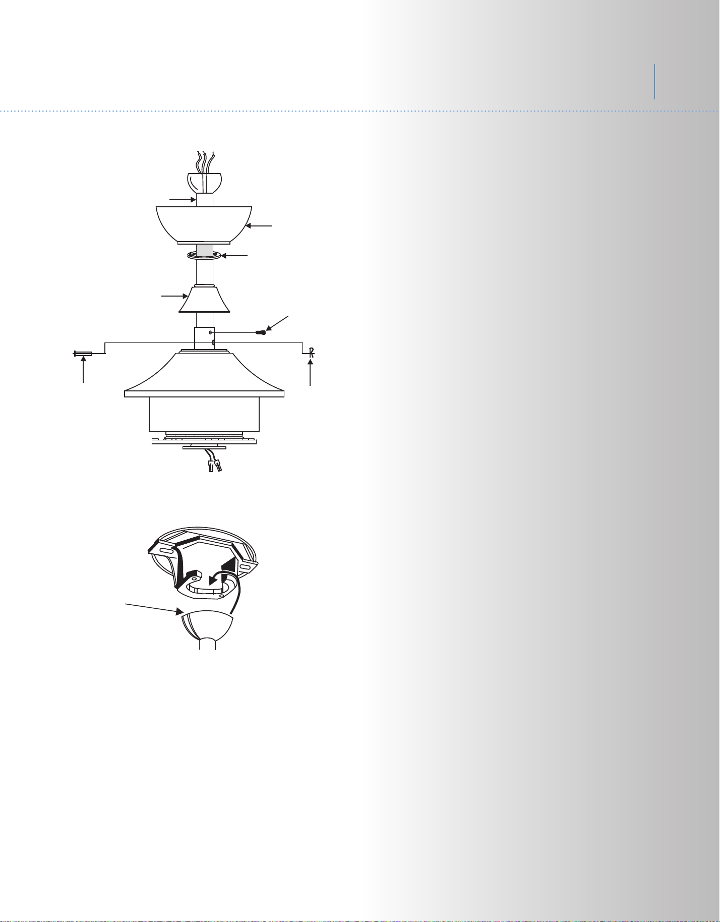
Step 8. Slip the coupling cover, canopy cover
and canopy onto the downrod.
Thread the hanger ball onto the downrod,
insert the cross pin through the downrod and
tighten. Now tighten the set screw. (Fig. 9)
Step 9. Lift the motor assembly into position
and place the hanger ball into the ceiling
mounting bracket.
Rotate the entire assembly until the "Check
Tab" has dropped into the "Registration Slot"
and seats rmly. (Fig. 10)
The entire motor assembly should not rotate
(left or right) when seated properly.
WARNING: Failure to reattach the cross pin
and seat the "Check Tab" can cause the fan
to fall from the ceiling during operation. Take
special care to make sure this pin is
reattached.
Set screws
Hitch pin
Retaining clip
Coupling cover
7
Fig. 11
Ceiling mounting
bracket
Attach
safety cable
to ceiling joist
with screw and
washer
Fig. 12
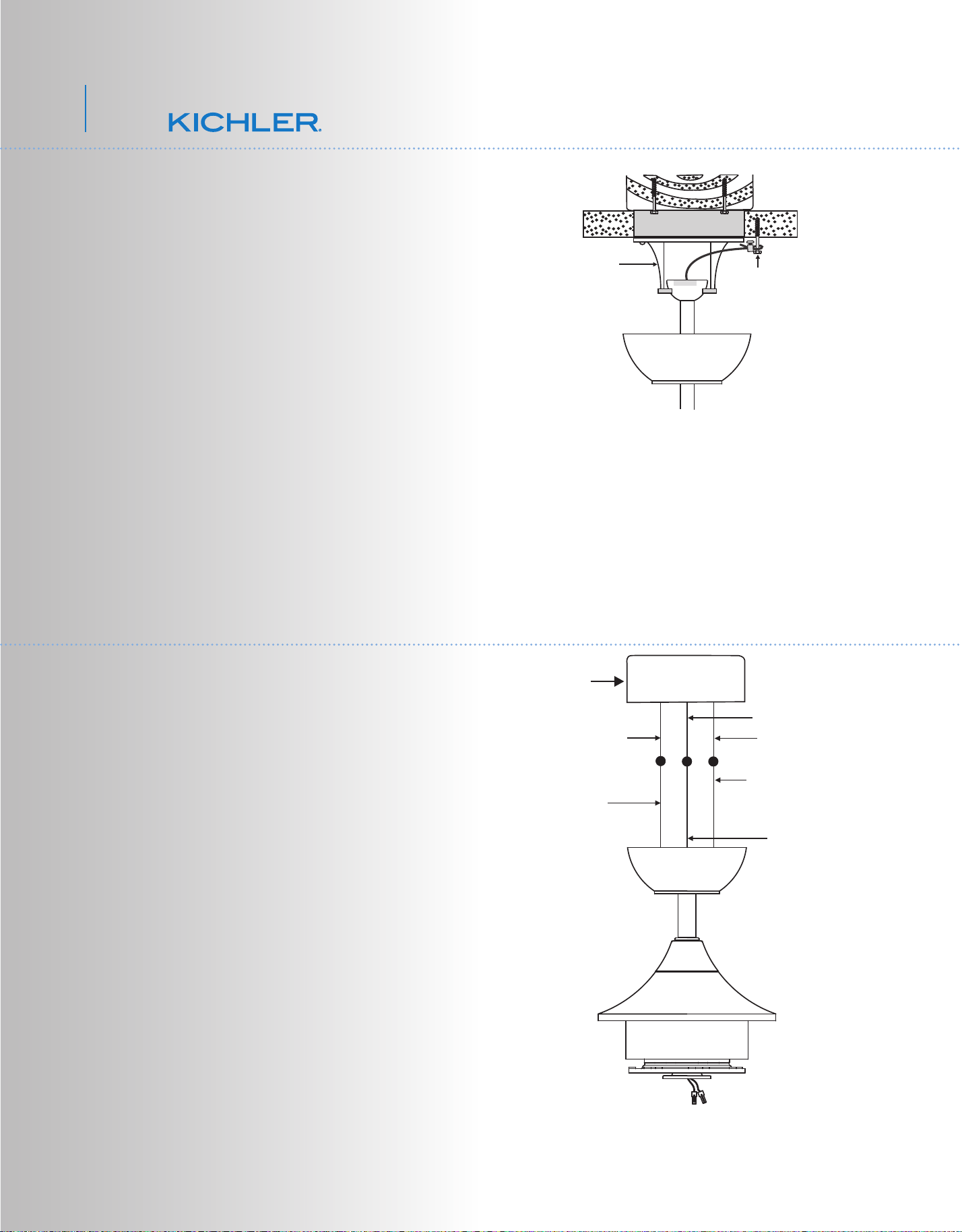
7. ELECTRICAL CONNECTIONS
6. INSTALLATION OF SAFETY SUPPORT
(required for Canadian installation ONLY)
A safety support cable is provided to help
prevent the ceiling fan from falling, please
install it as follows.
Step 1. Attach the provided wood screw and
washers to the ceiling joist next to the
mounting bracket but do not tighten. (Fig. 11)
Step 2. Adjust the length of the safety cable to
reach the screw and washers by pulling the
extra cable through the cable clamp until the
overall length is correct, put the end of the
cable back through the cable clamp, forming a
loop at the end of the cable. Tighten the cable
clamp securely. Now, put the loop in the end
of the safety cable over the wood screw and
under the washer. Tighten the wood screw
securely.
NOTE: Although the safety support cable is
required for Canadian installations only. It's a
good idea to make the attachment with any
installation.
WARNING: To avoid possible electrical shock,
be sure you have turned off the power at the
main circuit panel.
Follow the steps below to connect the fan to
your household wiring. Use the wire
connecting nuts suppled with your fan. Secure
the connectors with electrical tape. Make sure
there are no loose wire strands or connections.
Step 1. Connect the fan supply (black) wire to
the black household supply wire as shown in
Figure 12.
Step 2. Connect the neutral fan (white) wire to
the neutral household (white) wire.
Step 3. Connect the fan ground wire (green) to
the household ground wire.
Step 4. After connecting the wires, spread
them apart so that the green and white wires
are on one side of the outlet box and the black
and blue wires are on the other side.
Step 5. Turn the connecting nuts upward and
push the wiring into the outlet box.
White (neutral)
Green or bare
copper (ground)
White ("AC IN N")
Ground (green)
(Connect to ground wire
on hanger bracket if no
house ground wire exists.)
Outlet box
Black ("AC IN L")
Black (motor)
8
80” Lehr
TM
Step 1. Tuck all the connections neatly into
the ceiling outlet box.
Step 2. Slide the canopy up to the mounting
bracket and place one of the key hole slots
over the mounting screw on the mounting
bracket. Rotate the canopy until the screw
head locks in place at the narrow section of
the key hole. See figure 13.
Step 3. Align the remaining circular hole on
the canopy with the remaining hole on the
Ceiling Mounting Bracket. Insert and tighten
the mounting screw you removed earlier and
the mounting screw from Step 2 above. Now,
attach the canopy cover to the mounting
screw heads by inserting the screw heads into
the bottom side of the canopy cover and
rotating the cover clockwise.
NOTE: Adjust the canopy screws as
necessary until the canopy and canopy cover
are snug. (Fig. 13)
Warning: Make sure the "Check Tab" at the
bottom of the hanger bracket is properly
seated in the "Registration Slot" on the side of
the hanger ball before attaching the canopy to
the bracket. Failure to properly seat the
"Check Tab" could damage the electrical
wires when to ceiling fan blade direction is
changed while the fan is running.
8. FINISHING THE INSTALLATION
Fig. 13
Outlet box
Ceiling
mounting
bracket
Canopy
Canopy cover
Screws
Screws
9
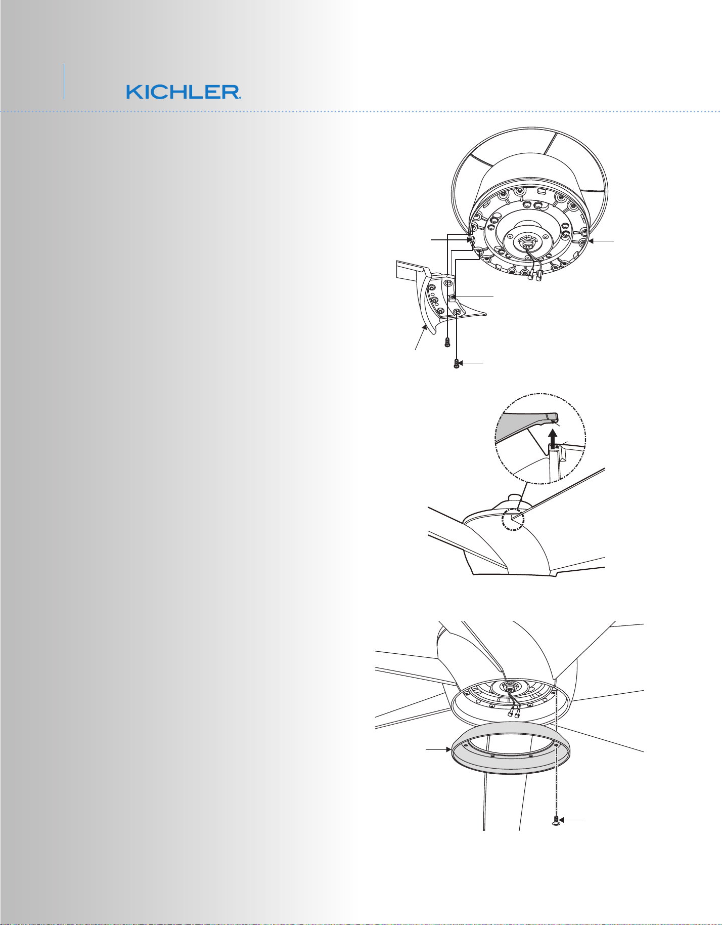
9. ATTACHING THE FAN BLADES
Step 1 Attach the rst blade assembly to the
fan motor by lining up the slot of the blade
assembly with the tab on the motor. Fasten
the blade assembly to the motor using two
screws and washer provided. (Fig. 14)
Step 2 Installing the second blade assembly
to the fan motor; lining up the slot of the blade
assembly with the tab on the motor, Insert the
tab in the second blade assembly to the slot
on the top of rst blade assembly (see the
drawing circled in Fig. 15)
Step 3 Follow the step 2 procedure for the
remaining blade assemblies.
10. ATTACHING THE BLADE
SUPPORT PLATE
Attach the blade support plate onto the blade
arms using the screws(7) provided after
completed installing all blades with arms onto
motor in order to secure the wall of blades
well. (Fig. 16)
Fig. 14
Fig. 15
Fig. 16
Blade
assembly
Screws
Motor
Tab
Slot
Slot
Tab
Screws
Blade
support
plate
10
80” Lehr
TM
Fig. 18
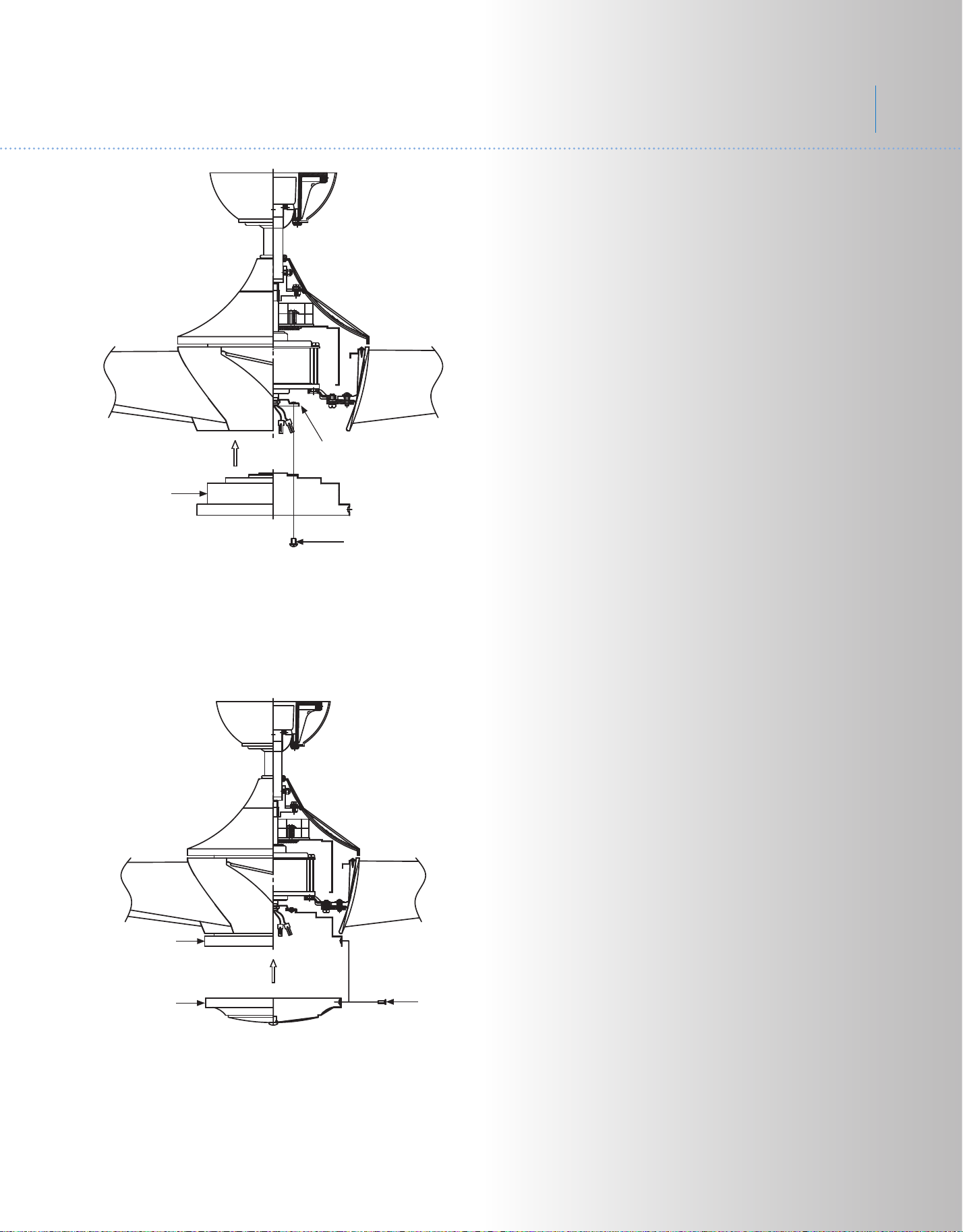
12. INSTALLING THE MOTOR
BOTTOM HOUSING
Step 1. Loosen the three mounting screws on
the inside of the motor bottom housing. (Fig.
18)
Step 2. Place the key holes on the motor
bottom housing over the 2 screws previously
loosened from the mounting plate, turn the
motor bottom housing until it locks in place at
the narrow section of the key holes. Secure by
tightening all three screws. (Fig.18)
Mounting
plate
Screws
Motor
bottom
housing
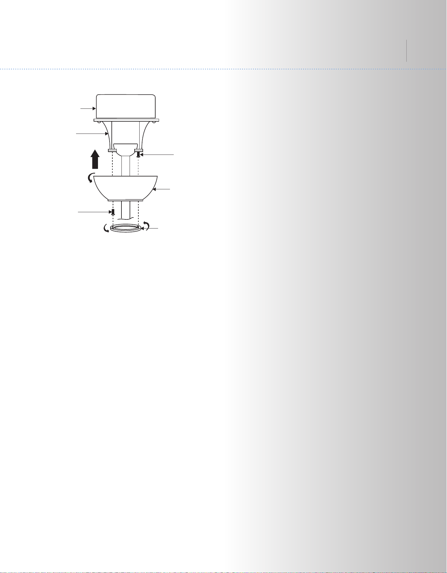
11. INSTALLING THE MOUNTING PLATE
Step 1. Loosen the two screws on the
mounting ring attached to the motor shaft and
"remove" and save the third screw. (Fig. 17)
Step 2. Place the key holes on the mounting
plate over the 2 screws previously loosened
from the mounting ring, turn mounting plate
until it locks in place at the narrow section of
the key holes. Secure by tightening the 2
screws previously loosened and the one
previously removed. (Fig. 17)
Fig. 17
Mounting
plate
Screws
Mounting ring
11
Fig. 19
Fig. 20
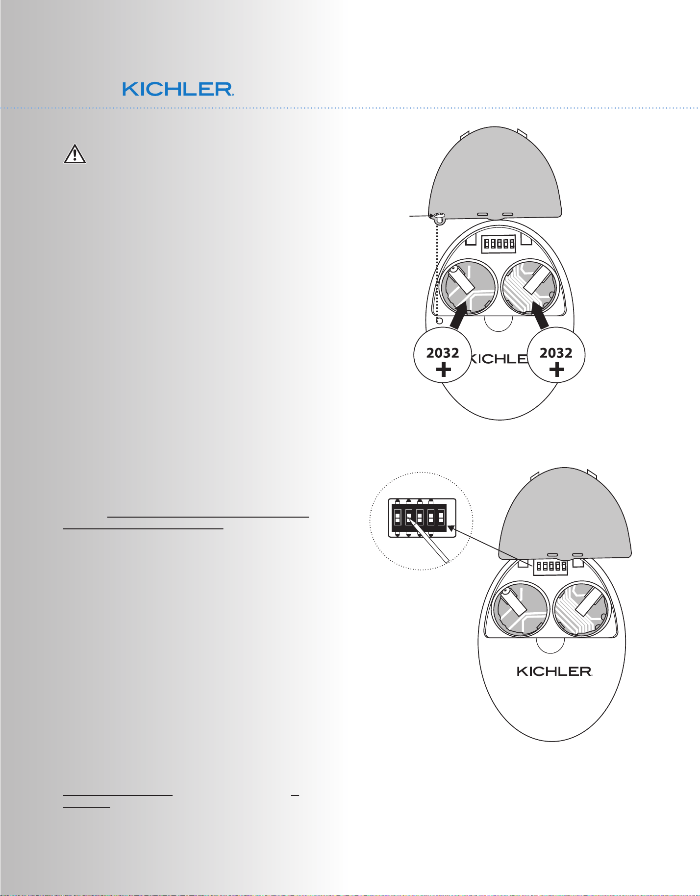
13. CONTROL SYSTEM SET-UP
ON
1 2 3 4
D
X
ON
Dip switch
TM
Set screw
WARNING: Chemical Burn Hazard. Keep
batteries away from children. This product
contains a lithium button/coin cell battery. If a
new or used lithium button/coin cell battery is
swallowed or enters the body, it can cause
severe internal burns and can lead to death in
as little as 2 hours. Always completely secure
the battery compartment. If the battery
compartment does not close securely, stop
using the product, remove the batteries, and
keep it away from children. If you think batteries
might have been swallowed or placed inside
any part of the body, seek immediate medical
attention.
a) The cells shall be disposed of properly,
including keeping them away from children;
and
b) Even used cells may cause injury.
Make sure the power is completely
disconnected before you begin this procedure.
SPECIAL NOTE:
Your new Kichler
®
Ceiling Fan is State of the Art
and employs a High Efficiency DC (direct current)
Motor with an advanced CoolTouch™ Remote
Control System. The DC Motor uses 70% less
energy than a conventional ceiling fan AC Induction
Motor. The DC motor is “Digitally” controlled and
operates differently than conventional ceiling fans
motors. Please read this portion of the manual
completely before proceeding.
Our CoolTouch™ Control system includes an
“Automatic Frequency Selection” feature. To set
the control frequency and program the control
system, follow these steps.
Open the back of the Transmitter. You need to use
a screwdriver to open or close the battery cover
(figure 19)
The Frequency Selector is a "Dip Switch Block"
inside the Battery compartment of the Transmitter.
(See figure 20) You change frequencies by
arranging the small switches numbered 1 through 4
in a up or down position. 16 possible frequencies
or combinations are possible.
The fifth switch, marked D and X sets the system
for operation with Incandescent or Fluorescent
Lamps. It is essential to set this switch correctly. If
your ceiling fan is equipped with Incandescent
Lamps set this switch to the D Position, for
Fluorescent Lamps, set the switch to the X
Position. If these settings are reversed, the lighting
control system will operate erratically and could
damage your ceiling fan.
12
80” Lehr
TM
Fig. 21
Fig. 22
Blue Light
Press/hold Button
3. Test the transmitter by pushing and releasing
ANY button briefly. A Blue Light should illuminate
under the 3-4 buttons. (Fig. 21) If not, check to
make sure the batteries are inserted and seated
correctly.
Power Up and Programming:
4. Follow the below steps to set the remote control:
The auto learning function will only mandate within
60 seconds when turning the fan’s AC power ON.
(Figure 22)
5. Select desired frequency from the back of
transmitter.
6. From the back of the transmitter, press “ ”
power button for 3 to 5 seconds. Light will blink
twice. The remote will now be programmed to your
fan and ready for use.
Try different speed setting on wall control to ensure
the fan is now fully functional. If programming is
unsuccessful, retry the process starting from step 6
again.
IMPORTANT: Do not interrupt the conditioning
until the fan comes to a complete stop in
approximately 5 minutes. All functions of the
control will be rejected during conditioning.
NOTE: The learning frequency function and self
calibration test will continue to retain the last set
frequency and calibration set even when the AC
power is shut off. If the frequency is changed the
self calibration test will occur again.
7. Your CoolTouch™ Control System is now
programmed and ready for use. Please see the
follow Operational Instructions.
The receiver provides the following protective
function:
1. Lock position: The DC motor has a built-in safety
against obstruction during operation. If there is an
obstruction, the motor will stop and then the power
will automatically go off in 30 seconds. Remove the
obstruction and reset.
2. Over 80W protection: When the receiver detects
motor power consumption which is greater than
80W, the receiver power will be stopped and
operation will immediately discontinue. Wait for 5
seconds and then turn the receiver power back on.
13
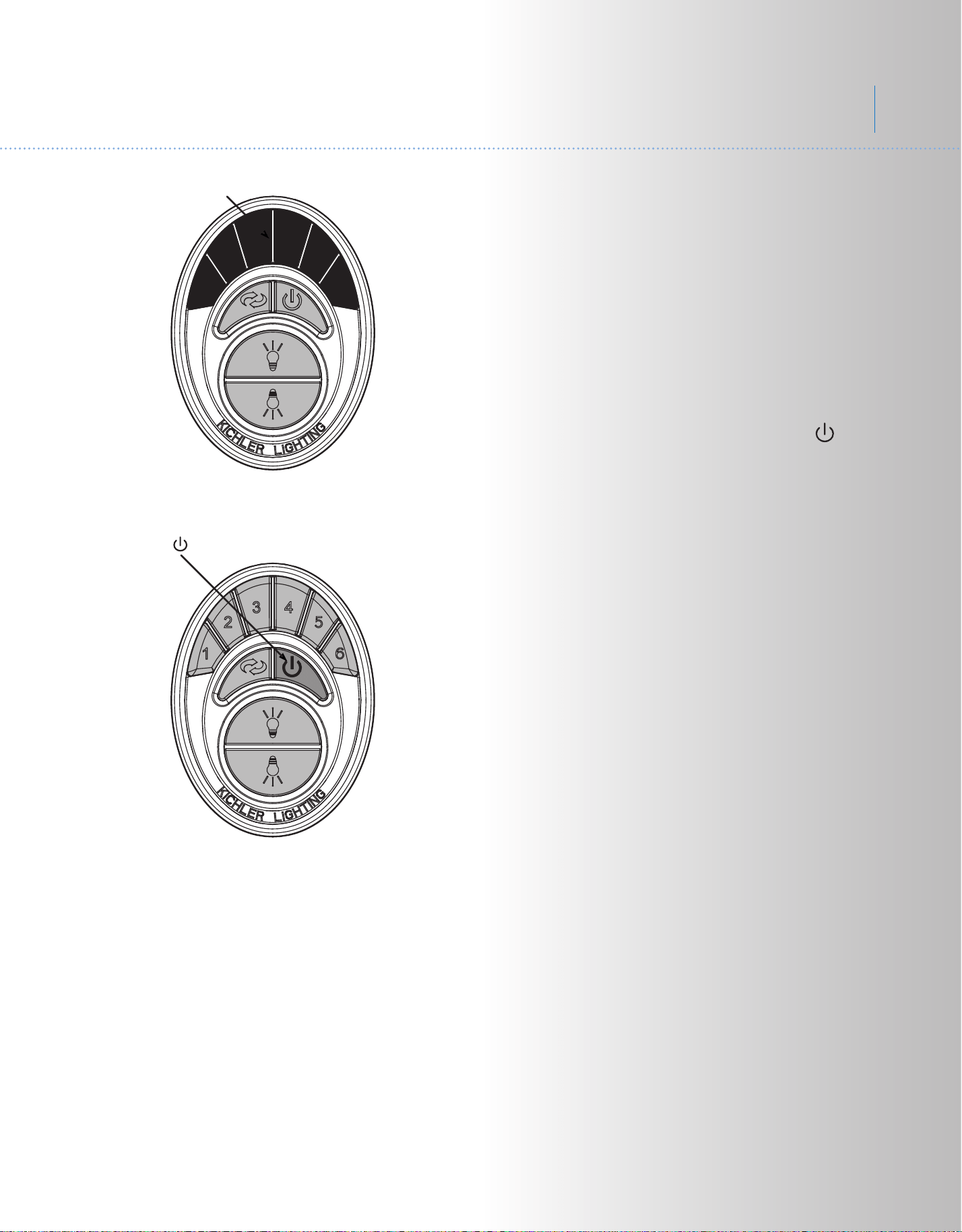
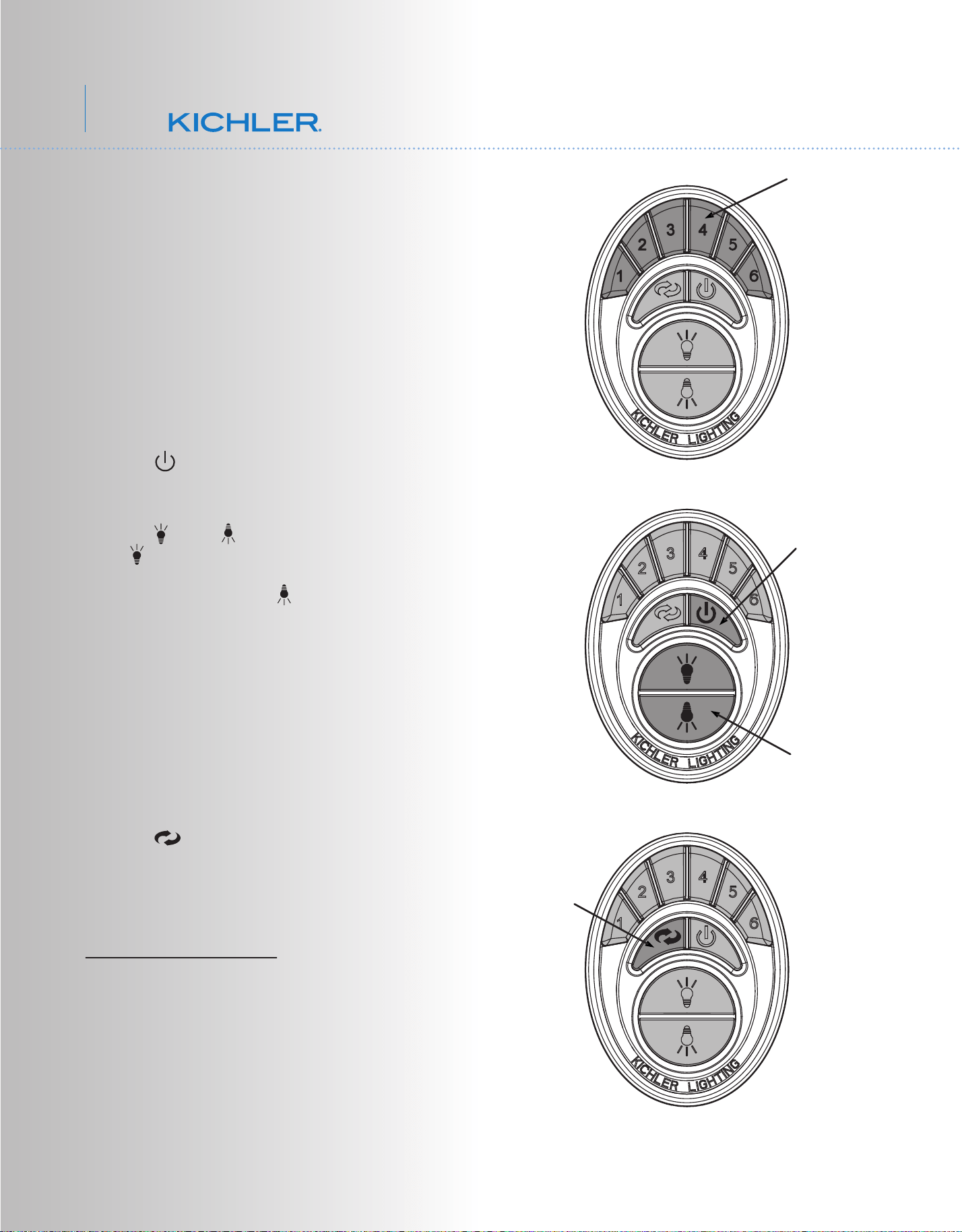
Fig. 23
Figure 23
1. Buttons 1, 2, 3, 4, 5 and 6 are used to set
the blade speed as follows:
1 = Low Speed
2 = Medium Low Speed
3 = Medium Speed
4 = Medium High Speed
5 = High Speed
6 = Extra High Speed
Figure 24
2. The " " button:
This button turns the fan motor off and is also
used in the program procedure.
3. The " " and " " button:
The " " button turns the upper light ON or
OFF and also controls the brightness setting
on some models. The " " button turns the
bottom light ON or OFF and also controls the
brightness setting.
Press and hold either button to set the desired
brightness level. The next time you turn the
light on, the system will remember this setting.
Press and release either button to turn the
light ON or OFF.
Figure 25
4. The " " button is used to set the fan in
forward or reverse operation. Each time you
press this button the fan blades will reverse
direction. This button functions ONLY when
the fan blades are in motion.
OPERATIONAL NOTE: Each time you start
the blades rotating, at any speed or reverse
the direction of the blades the Control System
will do a “Self Check” to insure operational
integrity. The blades will rotate slowly a short
distance (¼ turn), pause, change directions,
rotate ¼ turn, then build up RPM'S to the
selected speed. This is a perfectly normal
procedure and insures normal operating
performance.
14. OPERATING INSTRUCTIONS:
Fig. 24
Fig. 25
Motor Off Button
Light Control Buttons
Forward/Reverse
Button
Speed Buttons
14
80” Lehr
TM
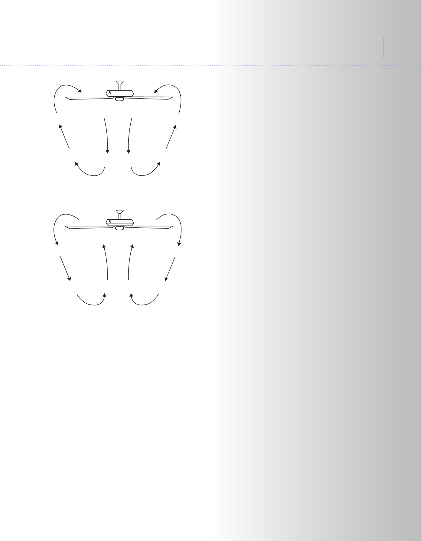
Fig. 26
Fig. 27
NOTE: Please remember your control system
is an RF (Radio Frequency) control system.
You may occasionally experience control
problems because of other radio frequency
interference, i.e. fan turns off, light turns off or
won't turn on, speed changes, etc. If this
should happen, just change the “Control
Frequency” by turning the power off and
repeating steps 1 through 6 under System
Programming.
Speed settings for warm or cool weather
depend on factors such as the room size.
Ceiling height, number of fans and so on.
Warm Weather Operation: Forward (counter
clockwise) A downward airflow creates a
cooling effect as shown in Fig. 26. This allows
you to set your air conditioner on a warmer
setting without affecting your general comfort.
Cool Weather Operation: Reverse (clockwise).
An upward airflow moves warm air off the
ceiling areas as shown in Fig. 27. This allows
you to set your heating unit on a cooler setting
without affecting your general comfort.
15
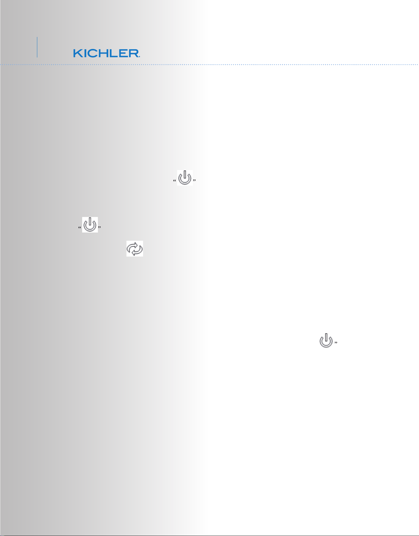
SENSOR DC CONTROL PAIRING PROCEDURES
IMPORTANT: Ceiling fan blades MUST be installed before pairing procedure can
begin.
Step 1. Program the wall control and/or the handset control separately. Once the
following pairing is successfully done, both the wall control and the handset control
can be used for the fan.
For wall control, press the power button to turn off the wall control
(the button will be up). Restore electricity to the ceiling fan branch circuit at the
circuit breaker or fuse box. Within 60 seconds of turning on the power, press the
power button to turn on the wall control (the button will be down), and
then press the " " reverse button for 3 to 5 seconds. Light will blink twice (if
there is a light on the fan) and fan will run for approximately 2 minutes in the upward
direction then reverse direction to down flow for additional 2 minutes. After that the
fan will stop running. The remote will now be programmed to your fan and ready for
use.
For handset control,
restore electricity to the ceiling fan branch circuit at the
circuit breaker or fuse box. Within 60 seconds of turning on the power, press
power button for 3 to 5 seconds. Light will blink twice (if there is a light on the fan)
and fan will run for approximately 2 minutes in the upward direction then reverse
direction to down flow for additional 2 minutes. After that the fan will stop running.
The remote will now be programmed to your fan and ready for use.
IMPORTANT: Do not interrupt the conditioning until the fan comes to a complete
stop in approximately 5 minutes. All functions of the control will be rejected during
conditioning.
Step 2. Try different speed setting on both the wall control and the handset control to
ensure the fan is now fully functional. If programming is unsuccessful, retry the
process starting from step 1 again.
16
80” Lehr
TM
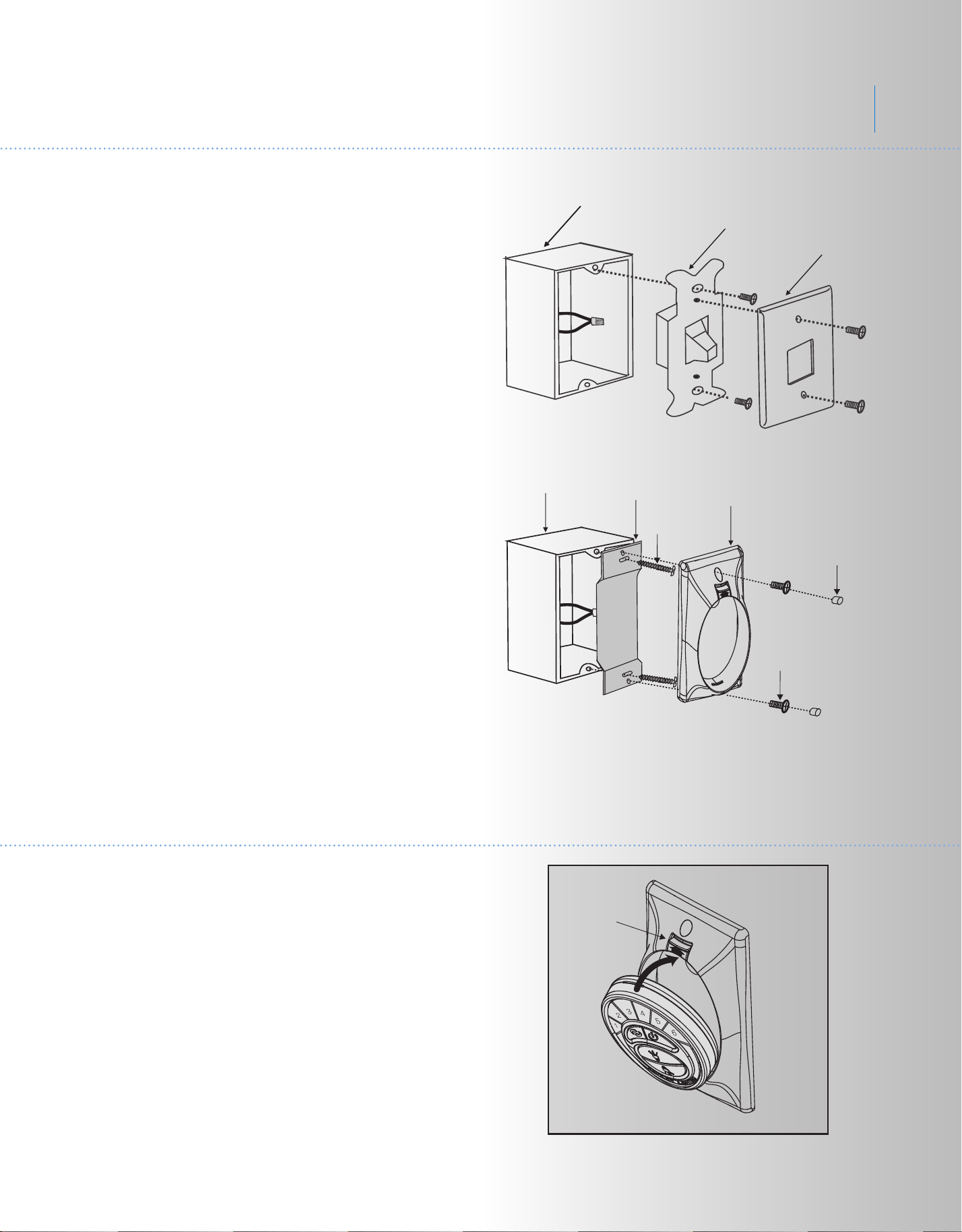
Fig. 28
Fig. 29
15. INSTALLING THE COOLTOUCH
™
CONTROL SYSTEM WALL PLATE
16. INSTALLING THE TRANSMITTER
1. Insert the transmitter into the wall plate by
inserting the bottom of the transmitter first
and then press the top of the transmitter into
the pocket. The transmitter will fully function
from this location or you can remove the
transmitter and use as a "Hand Held" device.
(Fig. 30)
2. To remove the transmitter from the wall
plate, push the release button and the
transmitter will fall into your hand.
Wall plate
Switch
Outlet box
Screws
Screws
Plastic plugs
CoolTouch
™
wall plate
Outlet box
Metal plate
Select a location to install your CoolTouch™
Control System Transmitter. You can replace
an existing wall switch or, install the
transmitter on ANY flat surface.
Option 1: Install the control system using an
existing wall switch outlet box.
Make sure the electrical power is TURNED
OFF at the main panel before continuing.
Step 1. Remove the existing wall plate and
the old switch from the wall outlet box. Wire
nut the BLACK leads (hot) together and push
back inside the outlet box. (Fig. 28)
Step 2. Install the metal plate and CoolTouch
™ wall plate to the existing wall outlet box
with 4 screws provided. Then place the two
plastic
plugs into the wall plate. (Fig. 29)
Option 2: Install the control system on ANY
flat surface.
Select the desired location and use the
CoolTouch™ wall plate to mark the location
for the mounting holes. Use the dry wall
anchors and/or screws provided and finish
the installation.
Release
button
Fig. 30

17
Problem
Fan will not start.
Fan sounds noisy.
Fan wobble.
Remote control
malfunction.
Solution
1. Check circuit fuses or breakers.
2. Check all electrical connections to insure proper contact. CAUTION: Make
sure the main power is OFF when checking any electrical connection.
3. Make sure the transmitter batteries are installed properly. Positive (+) side
facing out.
4. Insure the batteries have a good charge.
1. Make sure all motor housing screws are snug.
2. Make sure the screws that attach the fan blade brackets to the motor are
tight.
3. Make sure wire nut connections are not rubbing against each other or the
interior wall of the switch housing. CAUTION: Make sure main power is off.
4. Allow a 24-hour "breaking-in" period. Most noise associated with a new fan
disappear during this time.
5. If using an optional light kit, make sure the screws securing the glassware are
tight. Make sure the light bulbs are not touching any other component.
6. Do not connect this fan to wall mounted variable speed control(s). they are
not compatible with ceiling fan motors or remote controls.
7. Make sure the upper canopy is a short distance from the ceiling. It should not
touch the ceiling.
1. Check that all blade and blade arm screws are secure.
2. Most fan wobbling problems are caused when blade levels are unequal.
Check this level by selecting a point on the ceiling above the tip of one of the
blades. Measure this distance. Rotate the fan until the next blade is positioned
for measurement. Repeat for each blade. The distance deviation should be
equal within 1/8".
3. Use the enclosed Blade Balancing Kit if the blade wobble is still noticeable.
4. If the blade wobble is still noticeable, interchanging two adjacent (side by
side) blades can redistribute the weight and possibly result in smoother
operation.
1. Ceiling Fans with remote control systems CAN NOT be operated in
conjunction with any other control system EXCEPT a basic On/Off wall switch,
if desired.
17. TROUBLESHOOTING
80” Lehr
TM
18
FCC INFORMATION
This device complies with part 15 of the FCC Rules. Operation is subject to the following two conditions:
1) This device may not cause harmful interference, and
2) This device must accept any interference received, including interference that may cause undesired
operation.
Note: This equipment has been tested and found to comply with the limits for a Class B digital device,
pursuant to part 15 of the FCC Rules. These limits are designed to provide reasonable protection against harmful
interference in a residential installation This equipment generates, uses and can radiate radio frequency energy
and, if not installed and used in accordance with the instructions, may cause harmful interference to radio
communications. However, there is no guarantee that interference will not occur in a particular installation. If this
equipment does cause harmful interference to radio or television reception, which can be determined by turning
following measures:
• Reorient or relocate the receiving antenna
• Increase the separation between the equipment and receiver.
from that to which the receiver is
connected.
• Consult the dealer or an experienced radio/TV technician for help.