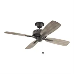
65” Eads Patio XL / 52” Eads Patio
TM TM

Eads Patio
3
ATTACHING THE FAN BLADE
INSTALLING THE SWITCH HOUSING
INSTALLING THE SWITCH COVER
INSTALLING THE FOB
INSTALLING AN OPTIONAL LIGHT FIXTURE
4
Eads Patio
5
PACKAGE CONTENTS
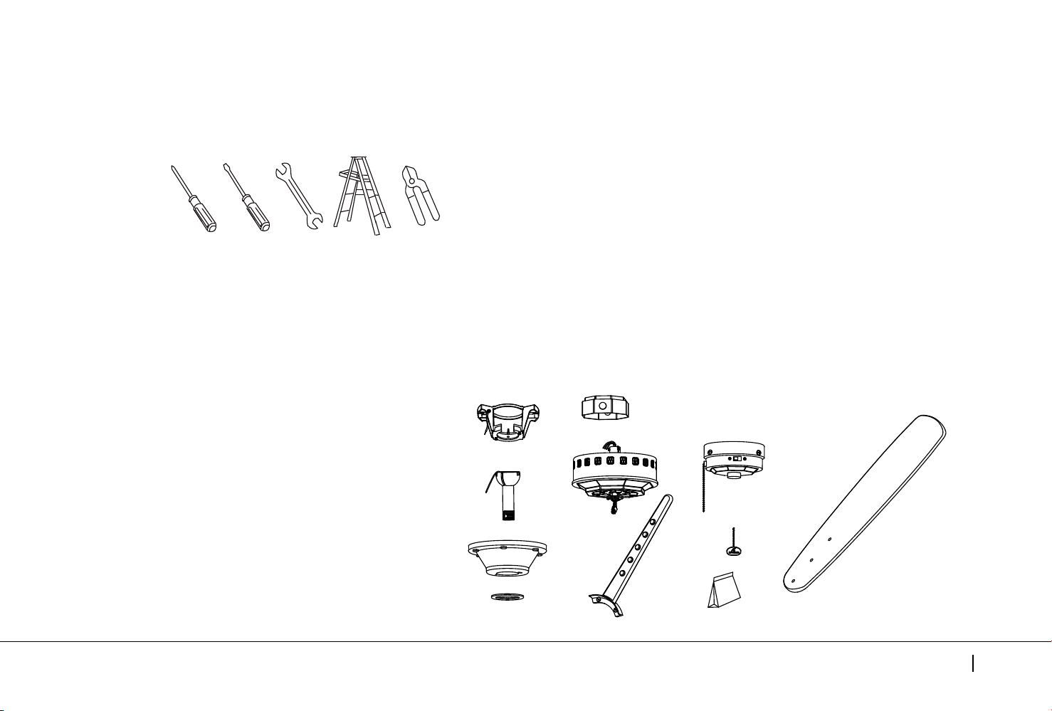
Unpack your fan and check the contents . You should have the following items:
Philips screw driver
Blade screw driver
11 mm wrench
Step ladder
Wire cutters
TOOLS AND MATERIALS REQUIRED
H
K
I
J
L
A
B
C
D
E
G
F
A. Mounting Bracket (1)
B. Ball / Downrod Assembly (1)
C. Canopy (1)
D. Canopy Hole Cover (1)
E. Coupling Cover (1)
F. Motor Body (1)
G. Blade Arm (4)
H. Fan Blades (4)
I. Switch Housing (1)
J. Switch Cover (1)
K. Fob (1)
L. Package Hardware
1) Mounting Hardware:
a. wood screws (2), screws (2), flat washers (2),
lockwashers (2), wire connectors (3)
2) Blade Attachment Hardware:
a. screws (14), washers (14)
3) Blade Arm Hardware:
a. screw (2)
4) Safety Cable Hardware:
a. wood screw (1), spring washer (1),
flat washer (1)
5) Balance Kit (1)
6) Screw Hardware:
a. screws (3)
6
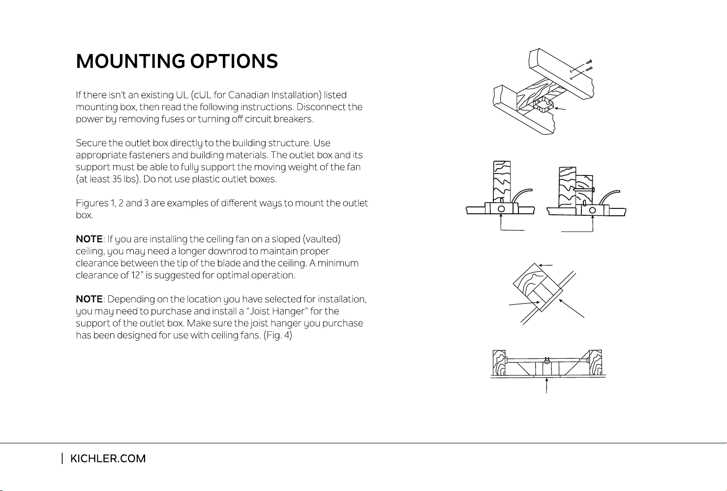
Outlet box
Provide strong
support
Recessed
outlet box
Ceiling
mounting
plate
Outlet box
Fig. 1
Fig. 3
Fig. 4
Outlet box
Fig. 2
ANGLED CEILING
MAXIMUM 30
°
ANGLE
Eads Patio
7
HANGING THE FAN
REMEMBER: To turn o the power before you begin installation.
This is necessary for your safety and also the proper programming
of the control system.
To properly install your ceiling fan, follow the
steps below.
Step 1. Before attaching fan to outlet box (not included), ensure
the outlet box is securely fastened to at least two points to a
structural ceiling member (a loose box will cause the fan to
wobble). Pass the 120 volt supply wires from the ceiling outlet
box through the center of the mounting bracket to outlet box in
ceiling using the screws and washers included with the outlet
box or screws and washers in the hardware bag. (Fig. 5)
Step 2. Remove the hanger ball from downrod assembly by
loosening set screws , removing the cross pin, and twisting
ball out of the rod. ( Fig. 6)
Fig. 6
Hanger Ball
Set Screw
Cross Pin
Downrod
Fig. 5
Outlet Box
Ceiling Mounting Bracket
Flat Washer
Screw
8
HANGING THE FAN
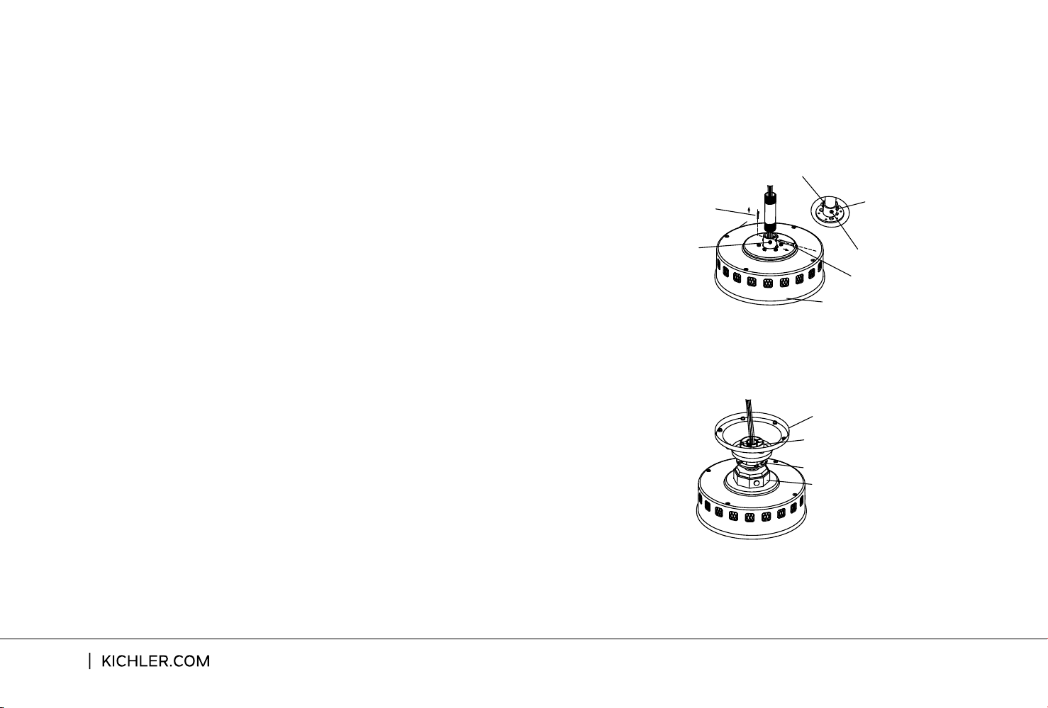
Step 4. Slip the coupling cover, canopy hole cover and canopy
onto the downrod. Carefully reinstall the hanger ball onto the
downrod . Make sure the cross pin is in the correct position and
screws are tight and the wires are not twisted. ( Fig. 8)
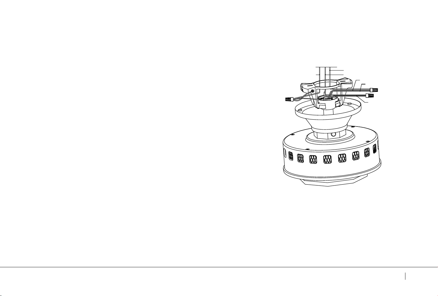
Step 3. Loosen the two set screws and remove the clip and cross
pin from the top coupling of the motor body.
Carefully feed the fan wires up through the downrod. Thread the
downrod onto the motor coupling until the cross pin holes are
aligned.Next, replace the cross pin and clip, and tighten both set
screws. (Fig. 7)
Motor Body
Cross Pin
Clip
Set Screw
Clip
Set Screw
Cross Pin
Fig. 7
Canopy
Hanger Ball
Canopy Hole Cover
Coupling Cover
Fig. 8
Eads Patio
9
HANGING THE FAN
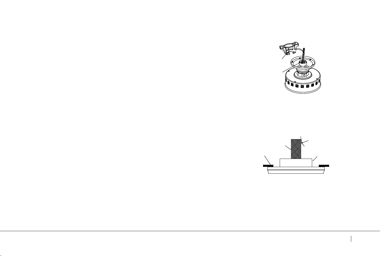
Step 5. Now lift the motor body into position and place the hanger
ball into the hanger bracket. Rotate until the "Check Tab" has
dropped into the "Registration Slot " and seats firmly. ( Fig. 9)
The entire motor body should not rotate if this is done correctly.
INSTALLATION OF SAFETY SUPPORT
(required for Canadian installation only)
WARNING: Failure to properly seat the "Check Tab" can damage
the ceiling fan during operation.
A safety support cable is provided to help prevent the ceiling fan
from falling, please install it as follows.
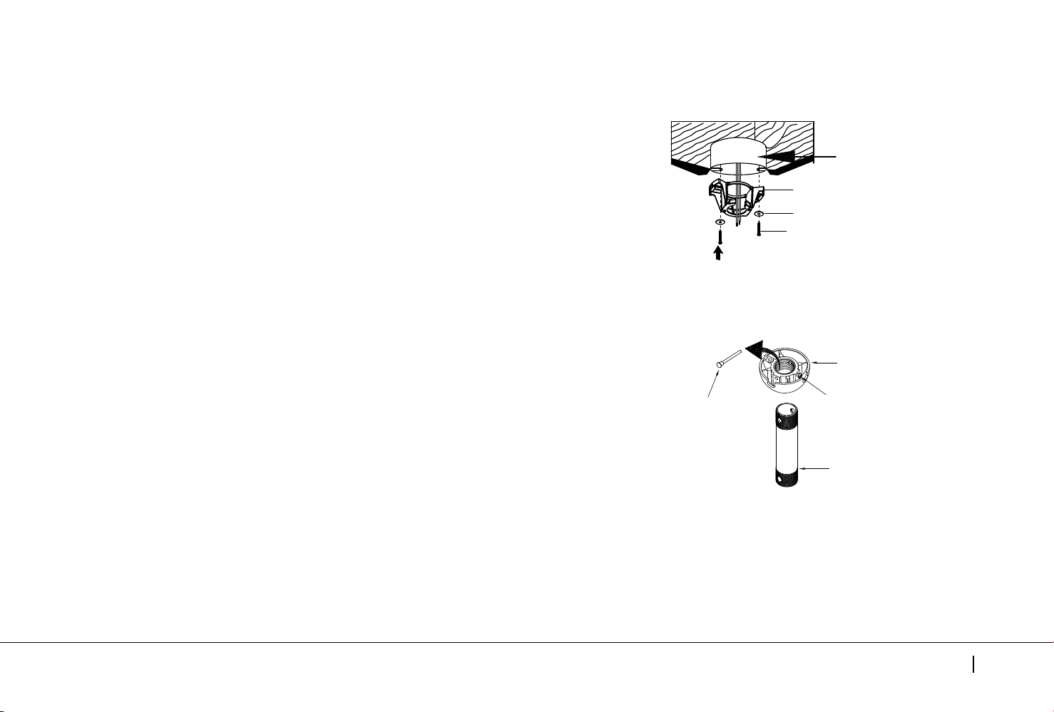
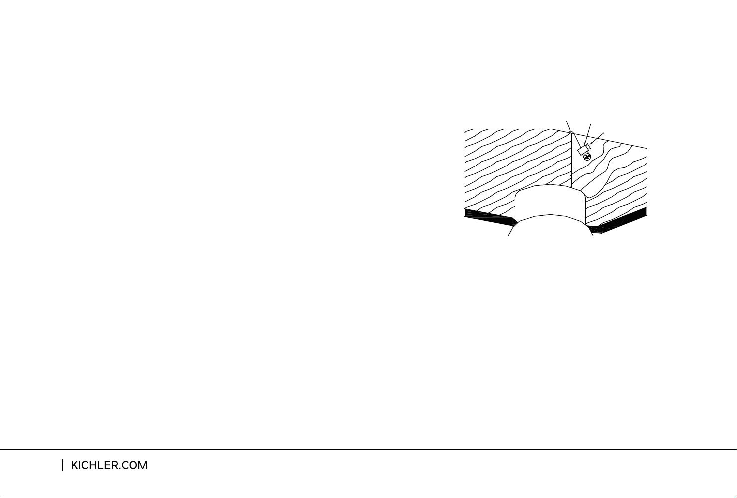
Step 1. Drive a wood screw and washers into the side of the brace
that holds the outlet box. Leave 3mm (1/8") of space between the
support brace and the washer. (Fig. 10)
Fig.10
Flat Washer
Wood Screw
Spring Washer
Outlet Box
Support Brace
Ceiling
Check Tab
Registration Slot
Fig. 9
NOTE: Although the safety support cable is required for Canadian
installations only. It’s a good idea to make the attachment with
any installation.
Step 2. Insert the safety cable through the mounting bracket and
one of the holes in the outlet box into the ceiling. Adjust the length
of the safety cable to reach the screw and washers by pulling the
extra cable through the cable clamp until the overall length is
correct, put the end of the cable back through the cable clamp,
forming a loop at the end of the cable. Tighten the cable clamp
securely. Now, put the loop in the end of the safety cable over the
wood screw and under the washer. Tighten the wood screw
securely. (Fig. 11)
10
Safety Cable
Bolt
Wood Screw
Fig.11
INSTALLATION OF SAFETY SUPPORT
(required for Candian installation only)
Eads Patio
11
MAKE THE ELECTRIC CONNECTIONS
WARNING: To avoid possible electrical shock, be sure you have
turned o the power at the main circuit panel before wiring.
WARNING: If your house wires are dierent colors than referenced
in this manual, stop immediately. A professional electrician is
recommended to determine proper wiring.
Step1. Connect the fan supply BLACK wire and fan light supply
BLUE wire to the BLACK household supply wire as shown in
Fig. 12.
Step 2.
Connect the fan neutral WHITE wire to the household
neutral WHITE wire as shown in Fig. 12.
Step 3.
Connect GROUND (GREEN) wires from mounting bracket
and downrod ball, to GROUND (GREEN) or BARE (COPPER) from
house.(Fig. 12)
Follow the steps below to connect the fan to your household
wiring.Use the wire connecting nuts supplied with your fan.
Secure the connector with electrical tape. Make sure there are
no loose wire stands or connections.
Step 4.
After making all of the above connecting,spread them
apart so the GREEN and WHITE wires to one side of the outlet box
and the BLACK wire toward the other side.
BLACK
BLUE
WHITE
GROUND
WHITE
BLACK
Fig. 12
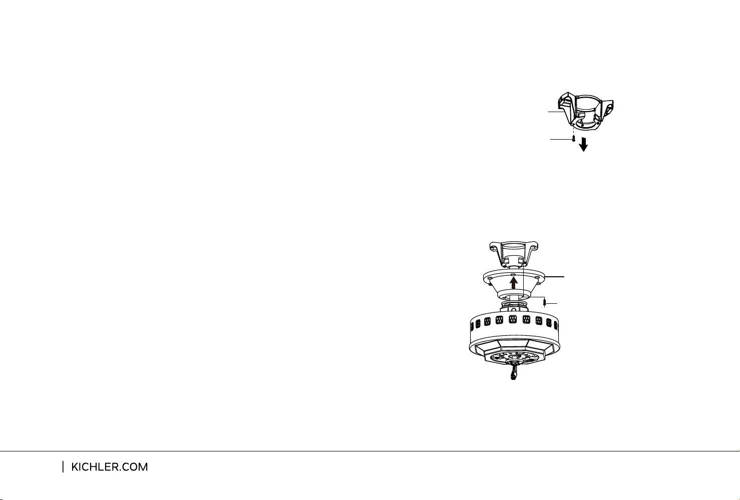
Fig.13
Mounting Bracket
Shoulder Screw
Fig.14
Canopy
Shoulder Screw
Step 1. Remove one of the two shoulder screws
in the mounting bracket. Loosen the second
shoulder screw without fully removing it.
(Fig. 13)
Step 2. Assemble canopy by rotating key slot in
canopy over shoulder screw in mounting bracket.
Tighten shoulder screw. Fully assemble and
tighten second shoulder screw that was
previously removed. (Fig. 14)
FINISHING THE INSTALLATION
12
FINISHING THE INSTALLATION
Step 3. Securely attach and tighten the canopy hole cover over the
shoulder screws in the mounting bracket utilizing the keyslot twist-lock
feature. (Fig. 15)
Fig.15
Canopy Hole Cover
Shoulder Screw
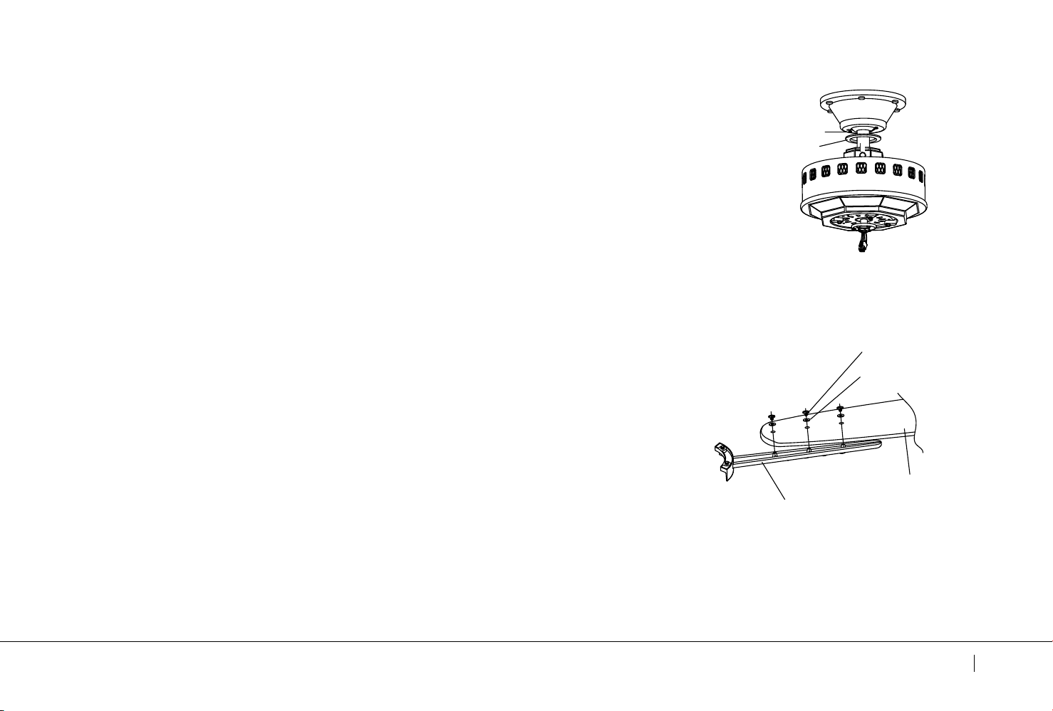
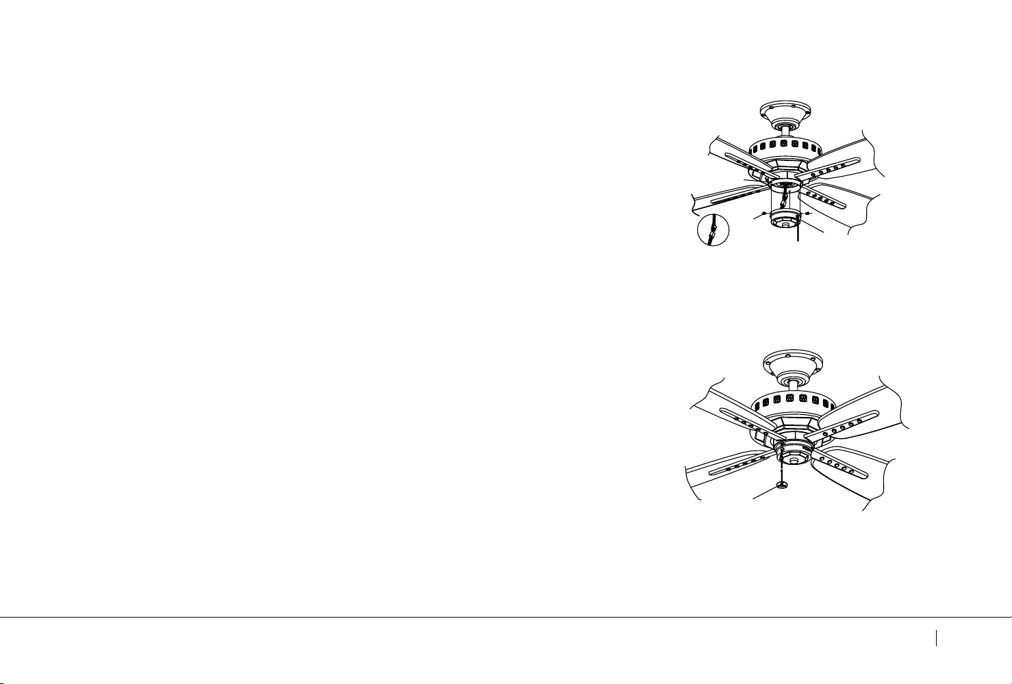
ATTACHING THE FAN BLADES
NOTE: Before continuing , make sure the power is disconnected by
turning o the circuit breaker of removing the fuse at the circuit box.
Step 1. Position the blade over the blade arm with threaded posts
showing. Make sure the bottom edge of the blade is fully seated
against the blade arm. With a Philips screwdriver, start a screw into
the blade arm (do not tighten) and repeat for the 2 remaining blade
screws and washers. Tighten each screw securely starting
with the center screw. Make sure the blade is straight. Repeat steps
for the remaining blades.(Fig. 16)
Fig.16
Blade Screw
Washer
Blade
Blade
Arm
Eads Patio
13
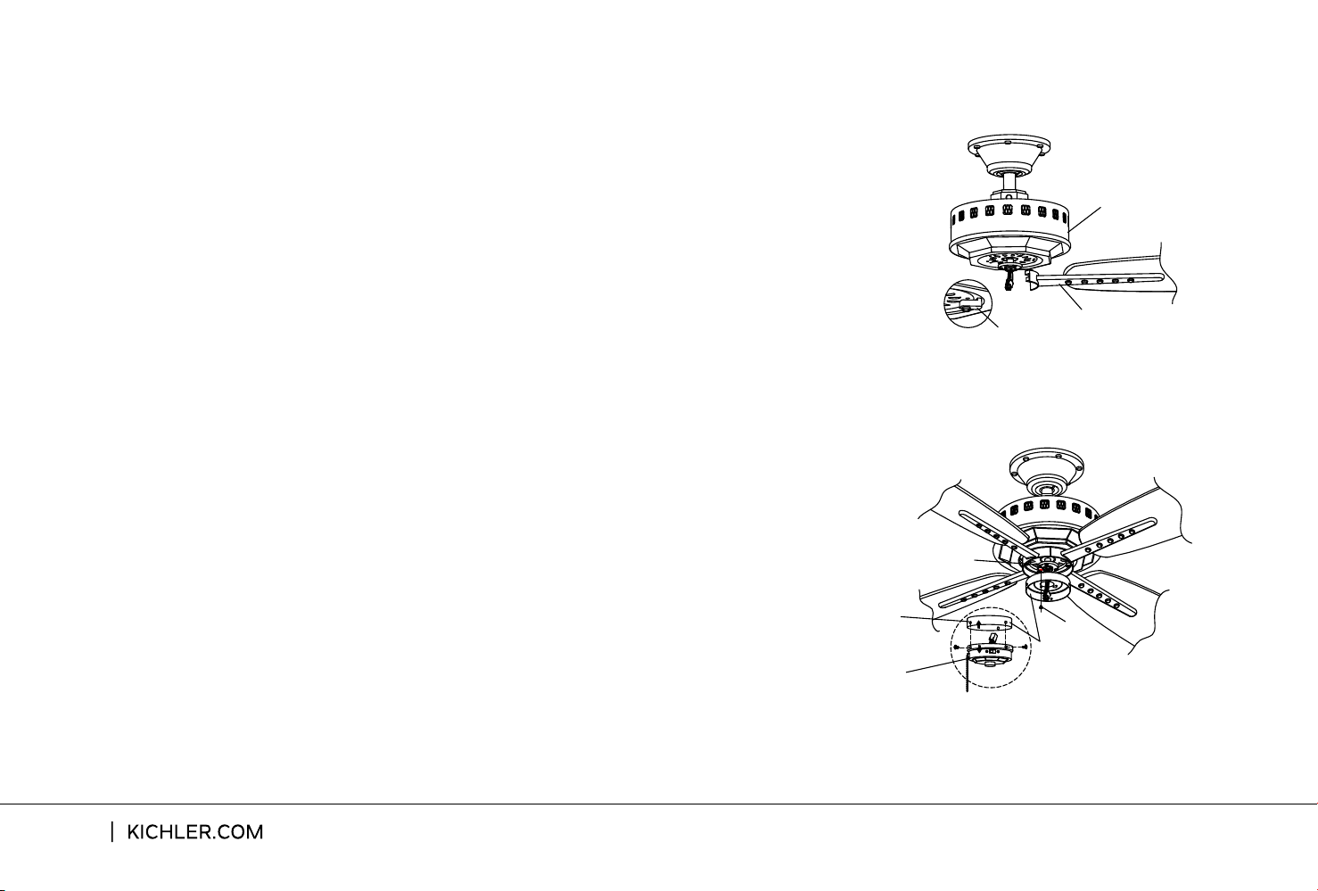
Step 2. Remove the shipping blocks from the bottom of the motor
body and discard. Fasten blade assembly to the holes located on
the bottom of the motor body Tighten the two "pre-installed" motor
screws in the blade arm. Repeat steps for the remaining blades
assemblies. (Fig. 17)
Step 2.
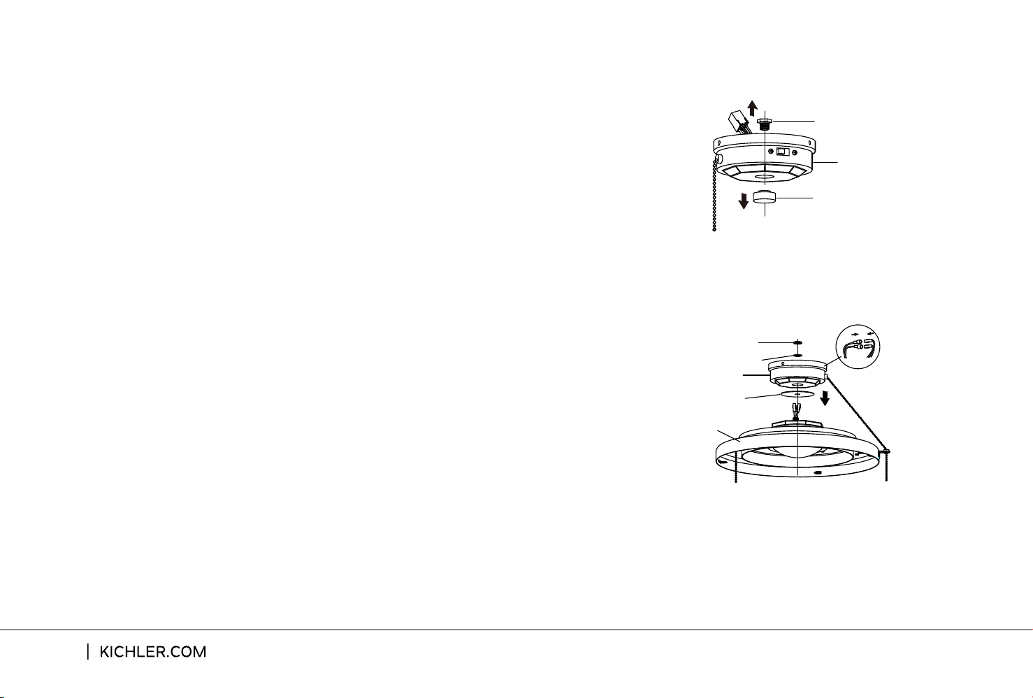
INSTALLING THE SWITCH HOUSING
ATTACHING THE FAN BLANES
Remove the screw on the mounting ring and loosen the other
two (do not remove). Let the 9-pin connector from motor body through
Step 1. Remove the three screws and separate the switch
honsing from the switch cover (Fig. 18)
the middle hole of switch housing. Align the two slot holes on the switch
housing over the 2 screws previously loosened from the mounting ring.
Turn the switch housing until it locks in place at the narrow end of the
key holes. Securely tighten all three screws. (Fig. 18)
Fig.17
Shipping Block
Motor Body
Blade
Assembly
14
Fig.18
Switch Housing
Mounting Ring
Switch Housing
Switch Cover
Screw
NOTE: Before continuing, make sure the power is disconnected
by turning o the circuit breaker of removing the fuse at the
circuit box.
NOTE: If you plan to install an “Optional” light fixture purchased
separately, please skip to page 16 and continue. If you want your
ceiling fan installed WITHOUT an “Optional” light fixture,follow
steps below.
Step 1 . The Square plastic wiring connector from the motor body
and switch cover will only fit together one way. Match up the color
on the side of each connector, then push them together until the
snap engages. (Fig. 19)
Step 2. Tuck the new connections neatly into the switch cover.
Align the switch cover with the screws on the edge of the switch
housing. Make sure all three screws are tight and secure. (Fig. 19)
INSTALLING THE FOB
INSTALLING THE SWITCH COVER
Step 1. Attach the decorative pull chain fob to the chain coming
out of the switch cover. Refer to Fig. 20.
Fig. 20
Fob
Eads Patio
15
Switch Housing
Screw
Switch Cover
Fig. 19
INSTALLING AN “OPTIONAL” LIGHT FIXTURE
Step 1. Remove the hex nut (1) and finial located in the bottom
of the switch cover by using a tooling. (Fig. 21) Keep them for
future use.
Step 3. Connect the BLACK wire connectors from the light
fixture and switch cover by pushing them together. Follow the
same procedure with the WHITE wire connectors. (Fig. 22)
Step 2. Feed the electrical wires from the light fixture through
the holes in the middle of the rubber washer and switch cover
(starting with one by one). Threaded the light fixture onto the
switch cover and make sure the pull chain hole on the switch
cover is nearest to the one of light fixture and pass it into the
hole. Add the lock washer and hex nut (2) onto the inside of the
switch cover and tighten securely. (Fig. 22)
16
Switch Cover
Finial
Hex Nut (1)
Fig. 21
Fig. 22
Hex Nut (2)
Lock Washer
Switch Cover
Light Fixture
Rubber Washer

Eads Patio
17
TROUBLESHOOTING
Problem Solution
Fan will not start.
Fan sounds noisy.
1. Check circuit fuses or breakers.
2. Check all electrical connections to insure proper contact. CAUTION: Make
sure the main power is OFF when checking any electrical connection.
3. Make sure the transmitter batteries are installed properly. Postive (+) side
facing out.
4. Insure the batteries have a good charge.
1. Make sure all motor housing screws are snug.
2. Make sure the screws that attach the fan blade brackets to the motor are
tight.
3. Make sure wire nut connections are not rubbing against each other or the
interior wall of the switch housing. CAUTION: Make sure main power is o.
4. Allow a 24-hour”breaking-in”period.Most noise associated with a new fan
disappear during this time.
5. If using an optional light kit,make sure the screws securing the glassware are
tight.Make sure the light bulbs are not touching any other component.
6. Do not connect this fan to a wall mounted variable speed control(s).They are
not compatible with ceiling fan motors or remote controls.
7. Make sure the upper canopy is a short distance from the ceiling.It should not
touch the ceiling.

18
TROUBLESHOOTING
Problem Solution
Fan wobble.
Remote control
malfunction.
1. Check that all blade and blade arm screws are secure.
2. Most fan wobbling problems are caused when blade levels are unequal.
Check this level by selecting a point on the ceiling above the tip of one of the
blades.Measure this distance.Roitate the fan until the next blade is positionged
for measurement.Repeat for each blade.The distance deviation should be
equal within1/8”.
3. Use the enclosed Blade Balancing Kit if the blade wobble is still noticeable.
4. If the blade wobble is still noticeable,interchanging two adjacent (side by)
side)blades can redistribute the weight and possibly result in smoother
operation.
1. Check Fans with remote control systems CAN NOT be operated in
conjunction with any other control system EXCEPT a basic On/O wall switch,
if desired.

Eads Patio
19