
Manual Revision #: 2023.12.13 MK
ANS Z21.58-2018 / CSA 1.6-2018
ANS Z21.58-2018 / CSA 1.6-2018
ANS Z21.58-2018 / CSA 1.6-2018
ANS Z21.58-2018 / CSA 1.6-2018
Master No. 211648
ASSEMBLY MANUAL
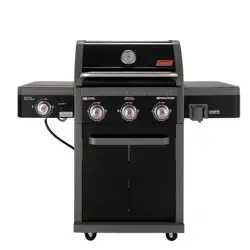
RV-301BBQ (G53261)
LIMITED 5-YEAR WARRANTY
Read and save manual for future reference.
Assemble your grill immediately. Missing or damaged parts
should be claimed within 30 days of purchase.
For product inquiries, parts, warranty and troubleshooting support,
please call 1-800-249-2506.
REVOLUTION
TM
3
BURNER

IMPORTANT SAFETY
WARNINGS
THIS MANUAL MUST REMAIN WITH
THIS PRODUCT AT ALL TIMES
Read and follow all safety statements,
assembly instructions, use and care directions
before attempting to assemble and cook.
Read and follow all safety statements,
assembly instructions, use and care directions
before attempting to assemble and cook.
Failure to follow all of the Manufacturer’s
instructions could result in hazardous fires,
explosions, property damage, or serious
personal injury or even death.
Follow all leak check procedures carefully prior
to operation of grill, even if grill was dealer
assembled. Do not try to light this grill without
reading the Lighting Instructions section of
the Safe Use and Care manual.
CAUTION
INSTALLER OR
ASSEMBLE /RCONSUMER
WARNING
1. If you smell gas:
a. Shut off gas to the appliance.
b. Extinguish any open flame.
c. Open lid.
d. If odor continues, keep away from the
appliance and immediately call your gas
supplier or your fire department.
2. Do not store or use gasoline or other
flammable liquids or vapors in the
vicinity of this or any other appliance.
3. LP gas cylinder not connected for use shall
not be stored in the vicinity of this or any
other appliance.
DANGER
CAUTION
IN DIRECT SUN, AND IN OPERATION, YOUR
GRILL’S STAINLESS STEEL AND PAINTED
STEEL PARTS CAN BECOME VERY HOT.
THIS GRILL IS FOR OUTDOOR USE ONLY
CONTACT CUSTOMER CARE IF ANY PARTS ARE MISSING.
1-800-249-2506
HARDWARE PACK
3
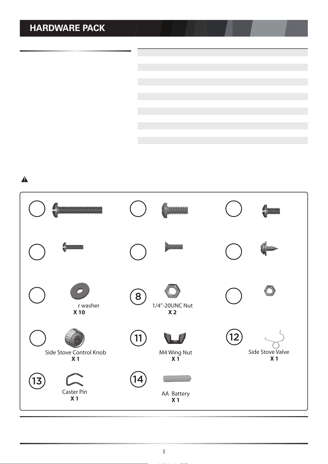
1/4”-20UNCx38 Screw
X 6
NO.10-24UNCX13 Screw
X 18
φ7 Fiber washer
X 10
1/4”-20UNCx16 Screw
X 26
NO.8-32UNCX18 Screw
X 2
1/4”-20UNC Nut
X 2
NO.8-32UNC Nut
X 2
NO.8-32UNCX10 Screw
X 3
ST4.2X10 Tapping Screw
X 9
M4 Wing Nut
X 1
Side Stove Control Knob
X 1
Caster Pin
X 1
1
2
3
4
5
6
7
8
9
10
11
12
13
No. Description Part Number Qty.
1 1/4-20UNCx38 Screw 20120-13038-250 6
2 1/4-20UNCx16 Screw 20120-13016-250 26
3 NO.10-24UNC x13 Screw 20124-10013-250 18
4 NO.8-32UNC x18 Screw 20132-08018-250 2
5 NO.8-32 X 3/8, Philips Flat Head 20332-08010-250 3
6 ST4.2X10 Tapping Screw 22500-42010-137B 9
7 φ7 Fiber washer G501-0054-9100 10
8 1/4"-20UNC Nut 30220-13000-250 2
9 NO.8-32UNC Nut 30232-08000-250 2
10 Side Stove Control Knob G532-3600-9000 1
11 M4 Wing Nut 33301-04000-032 1
12 Side Stove Valve Clip G405-0019-9200 1
13 Caster Pin G350-0026-9000 1
14 AA Battery G610-0028-9100 1
Side Stove Valve Clip
X 1
AA Battery
X 1
14
TOOLS NEEDED FOR ASSEMBLY
• #2 Phillips screwdriver (long and short)
• 1/4” Slotted screwdriver (long and short)
• Adjustable wrench
• Pliers
Caution:
Sheet metal can cause injury. Wear gloves when installing the grill.
BEFORE ASSEMBLING THIS GRILL , READ THE INSTRUCTIONS CAREFULLY.
Assemble the grill on a at, clean surface. Grill is heavy. Two people are recommended to
assemble this grill.

4
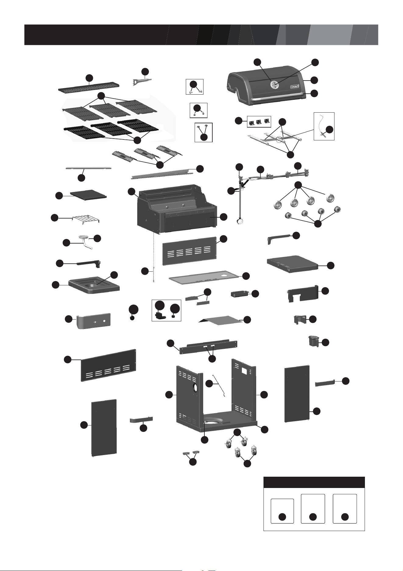
PARTS LIST FOR RV-301BBQ (G53261)
Item No. Qty. Description Part No.
AA 1 Top Lid Assembly G532-2000-02
AB 1 Lid Handle G532-0004-01
AC 1 Thermometer G532-0007-01
AD 1 Thermometer Bezel G532-0006-01
AE 2 Screw, Top Lid G466-0007-01
AF 2 Lid Bumper, Front G527-0002-02
AG 2 Lid Bumper, Rear G303-0038-01
BA 1 Burner Box Assembly G532-3100-01
BB 3 Main Burner G532-3500-01
BC 3 Carryover Assembly G354-0024-01
BD 3 Heat Distribution Plate G532-0016-01
BE 1 Grease Channel G532-0015-01
BF 3 Upper Cooking Grate G532-0081-01
BG 1 Cleaning Tool G532-0083-01
BH 1 Warming Rack G532-0018-01
BI 1 Match Holder G501-0068-01
BJ 1 Grease Channel Shield G532-0063-01
BK 3 Lower Cooking Grate G532-0080-01
BL 3 Main Burner Support G466-0047-01
CA 1 Manifold Assembly G532-D500-01
CB 1 Regulator G606-0008-01
CC 1 Side Stove Valve G532-0072-01
CD 1 Metal Hose, Side Stove G401-0068-01
CE1 1 Electronic Ignition Assembly G532-0019-01
CE2 1 Ignition Battery Cover G532-0019-02
CE3 1 Instastart™ Ignition Button G532-0082-01
CF 1 Electrode Set, Main Burner G515-0067-01
CG 3 Control Knob G532-3600-01
CH 4 Knob Bezel G363-0026-01
CI 1 Control Panel G532-0098-01
CJ 1 Front Brace G532-9000-01
CK 1 Grease Cup - Burner Box G416-0015-01
CL 2 Grease Cup Rails G466-0034-01
CM 1 Upper Back Panel G532-0067-01
CN 1 Lower Back Panel G532-0066-01
CO 1 Heat Shield - Burner Box G532-0023-01
CP 1 Heat Shield - Tank G532-0033-01
CQ 1 Tank Exclusion Wire G532-0077-01
Item No. Qty. Description Part No.
DA 1 Side Stove Side Shelf, Left G532-0900-01
DB 1 Side Shelf Fascia, Left G532-J600-01
DC 1
Side Shelf Table Rear Brace,
Left
G532-1300-01
DD 1 Side Stove Burner G532-5200-01
DE 1 Side Stove Support Drip Pan G515-0083-03
DF 1 Electrode Set, Side Stove G515-0039-02
DG 1 Side Stove Lid G532-0029-01
DH 1 Side Stove Cooking Grate G501-0077-01
DI 1 Side Shelf Table, Right G532-0030-01
DJ 1 Side Shelf Fascia, Right G532-K000-02
DK 1
Side Shelf Table Rear Brace,
Right
G532-1700-01
DL 1
Grease Cup Holder - Flare-
Free
G532-0031-02
DM 1 Grease Cup - Flare-Free G532-0031-02
EA 1 Cart Side Panel, Left G532-1000-02
EB 1 Cart Side Panel, Right G532-1100-02
EC 1 Left Door Assembly G532-9100-01
ED 1 Right Door Assembly G532-9200-01
EE 2 Door Handle G532-0026-01
EF 1 Bottom Shelf G532-0600-02
EG 2 Locking Castor G350-0023-01
EH 2 Castor G350-0024-01
EI 2 Door Magnet Assembly G527-0037-01
F1 1 Hardware Pack G532-B061-01
F2 1 Assembly Manual G532-M061-01
F3 1 Safe Use and Care Manual G363-M061-02
F4 1 Tank Screw G505-0047-01
5
EXPLODED DIAGRAM FOR RV-301BBQ (G53261)
CK
DI
CN
ED
EE
EG
EH
EI
F4
DK
BE
BJ
AA
AB
DL
DM
DJ
CP
CI
EI
EC
EA EB
DC
DG
DH
DD
DF
CQ
DB
DA
DE
BI
CO
CM
CE3
CE1
CE2
EE
BH
BG
BA
BB
AE
AG
AF
BK
BD
BF
AC
AD
CF
CA
CD
CC
BC
CL
Extras
Hardware
Pack
Assembly
Manual
Safe Use
& Care
Manual
F1 F2 F3
CB
BL
CG
EF
CH
CG
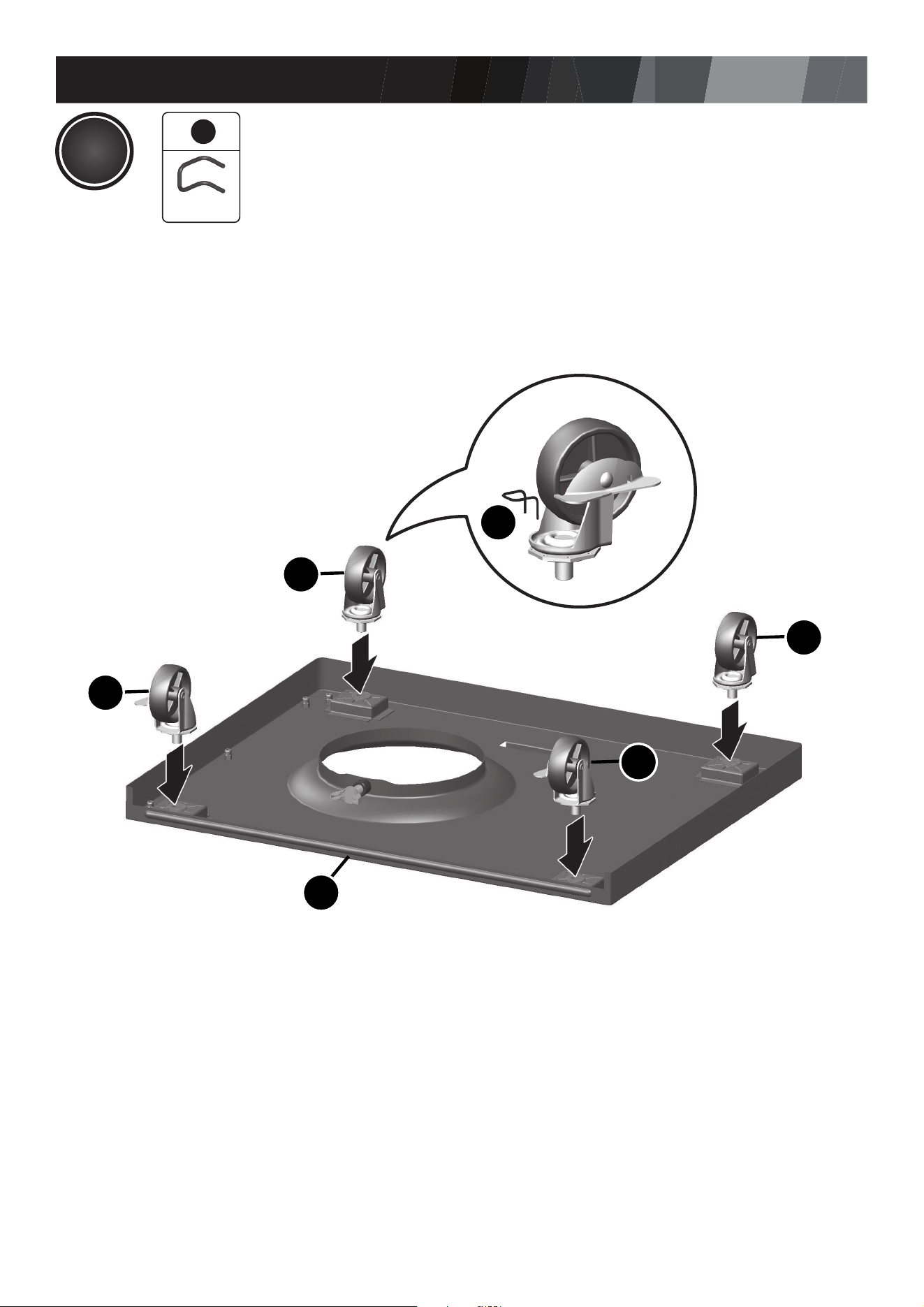
ASSEMBLY INSTRUCTIONS
6
EF
EG
EH
EG
EH
13
6
13
X 1
1
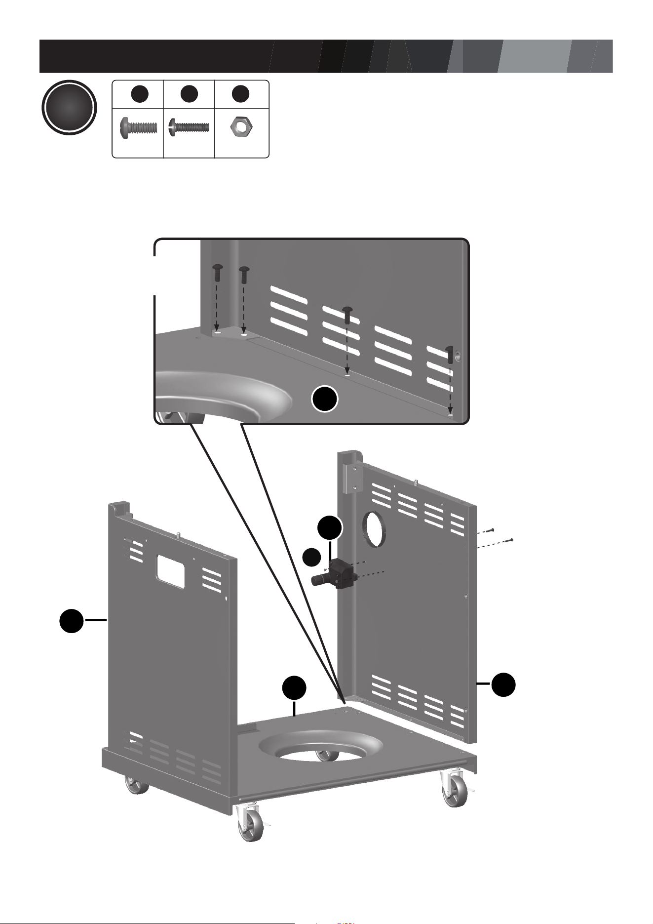
ASSEMBLY INSTRUCTIONS
7
EA
EB
EF
CE1
66
94
X 2X 2
6
2
X 8
2
EF
2X
A
9
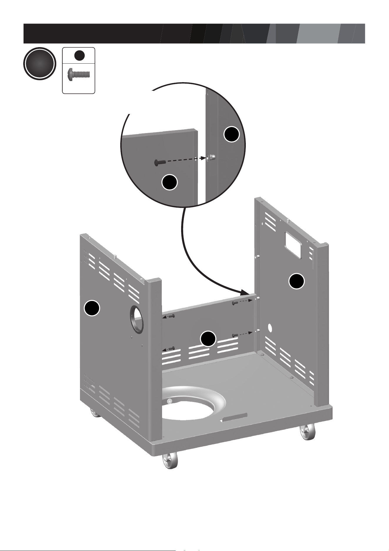
ASSEMBLY INSTRUCTIONS
8
4X
6
2
X 4
CN
CN
EB
EB
EA
3
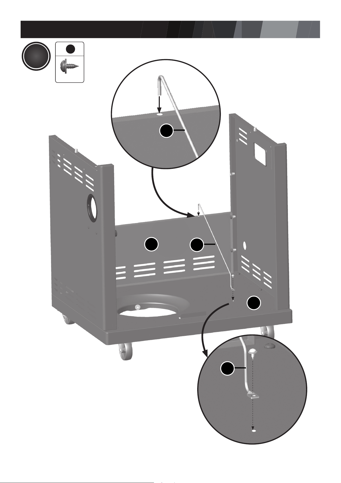
ASSEMBLY INSTRUCTIONS
9
CN
EF
6
6
X 1
CQ
CQ
CQ
4
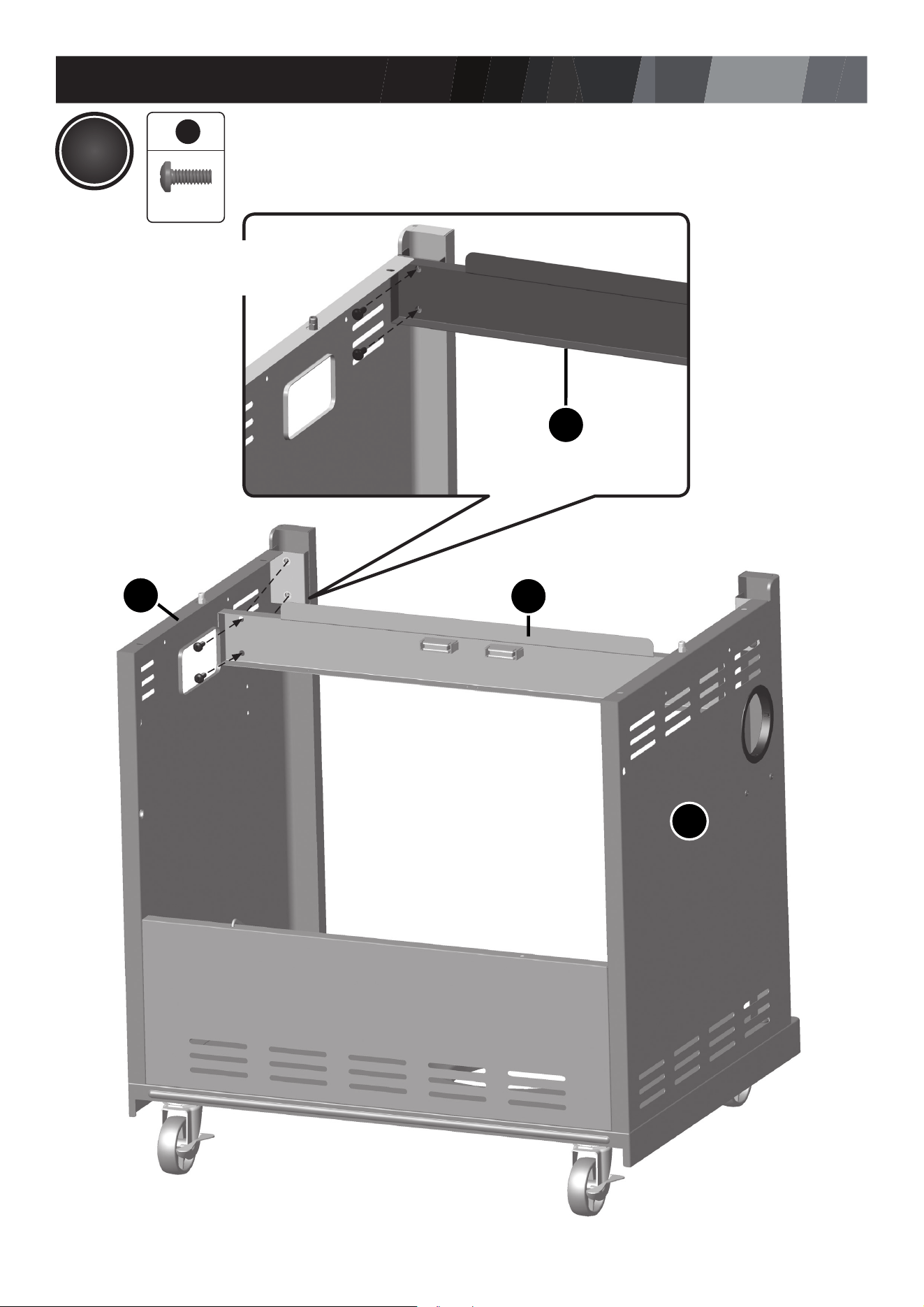
ASSEMBLY INSTRUCTIONS
10
5
2X
6
2
X 4
CJ
CJ
EA
EB
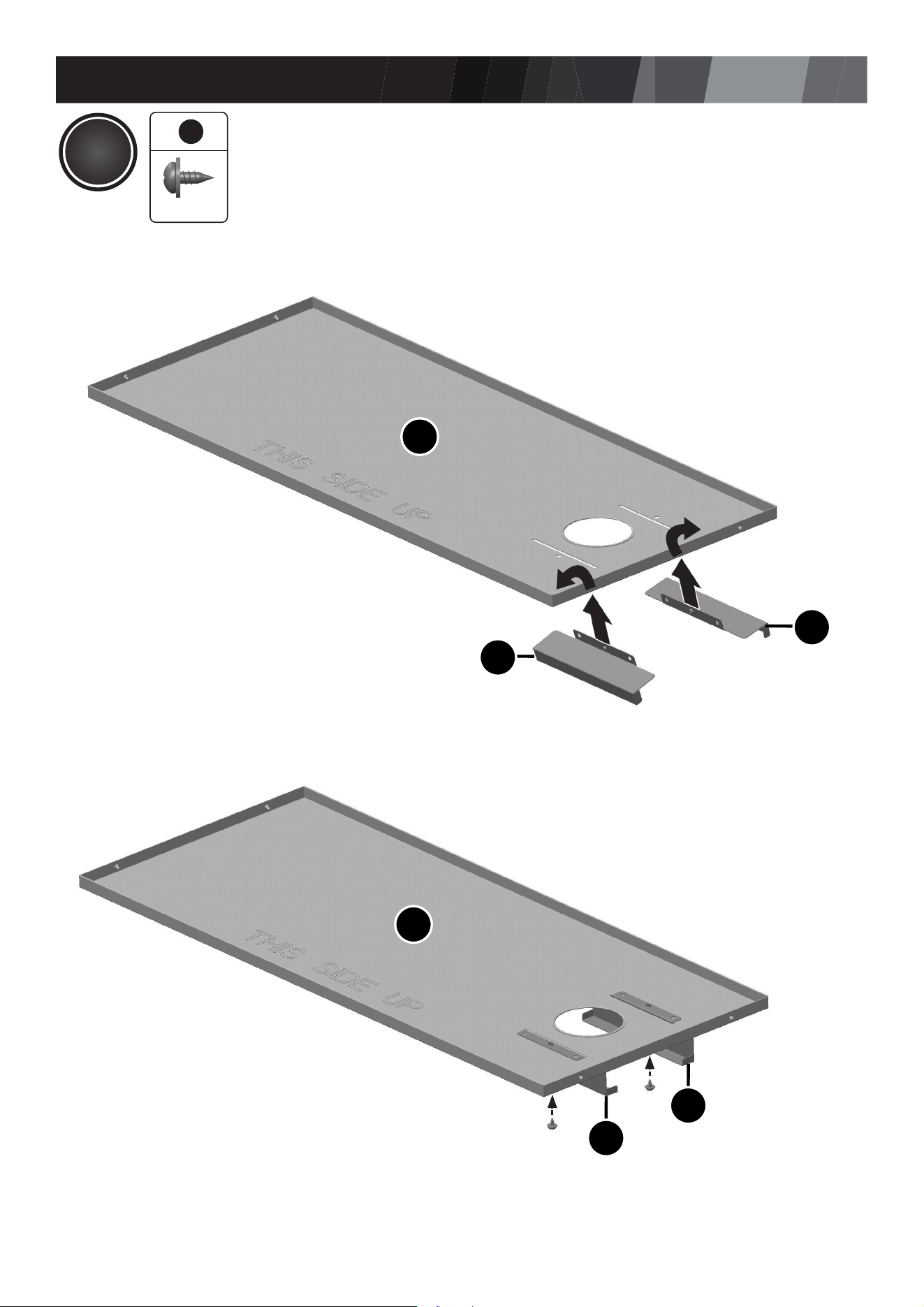
ASSEMBLY INSTRUCTIONS
11
6
CO
CO
CL
CL
CL
CL
6
6
X 2
A.
B.
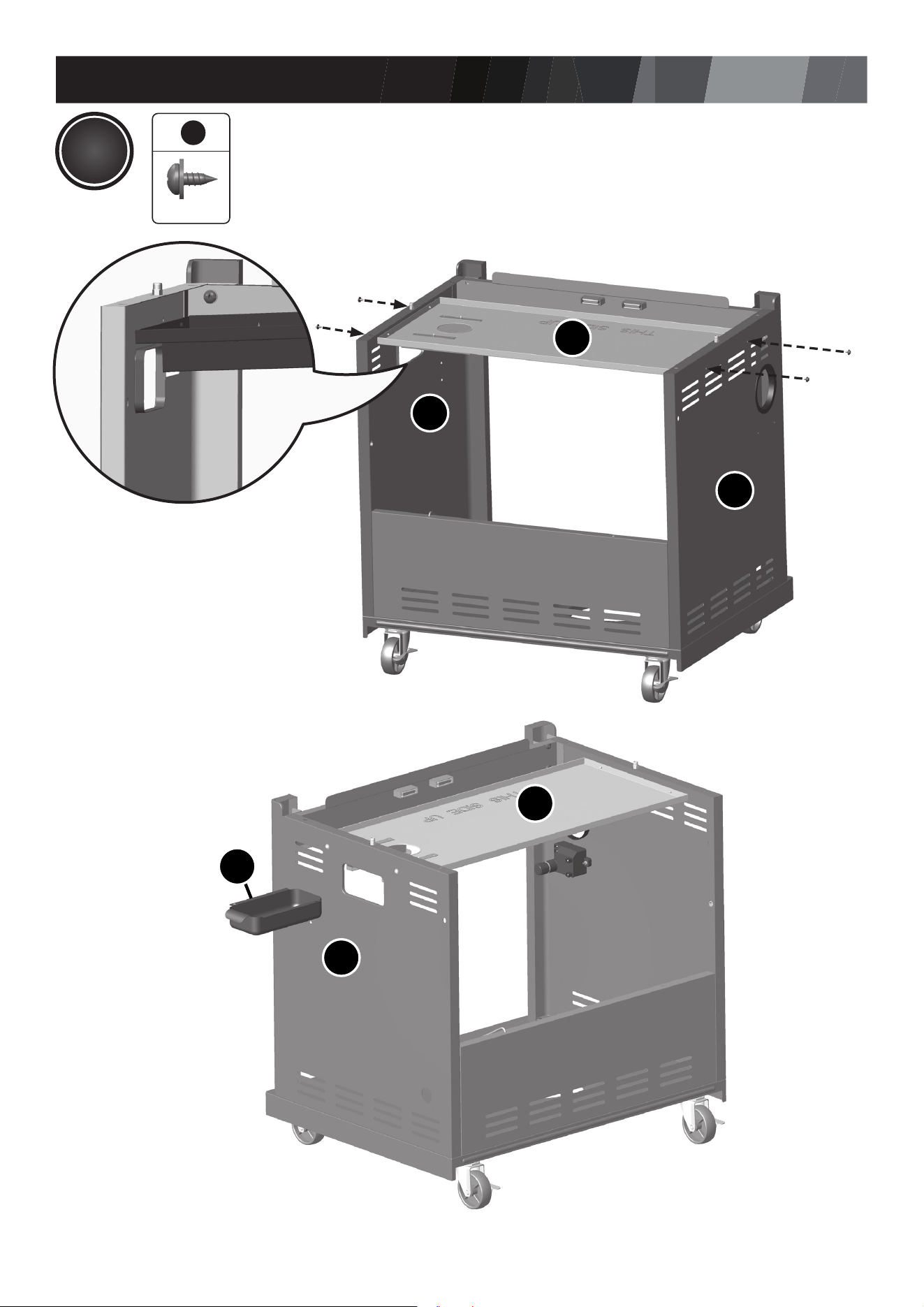
ASSEMBLY INSTRUCTIONS
12
6
CO
CO
EB
EB
EA
CK
C.
D.
6
6
X 4
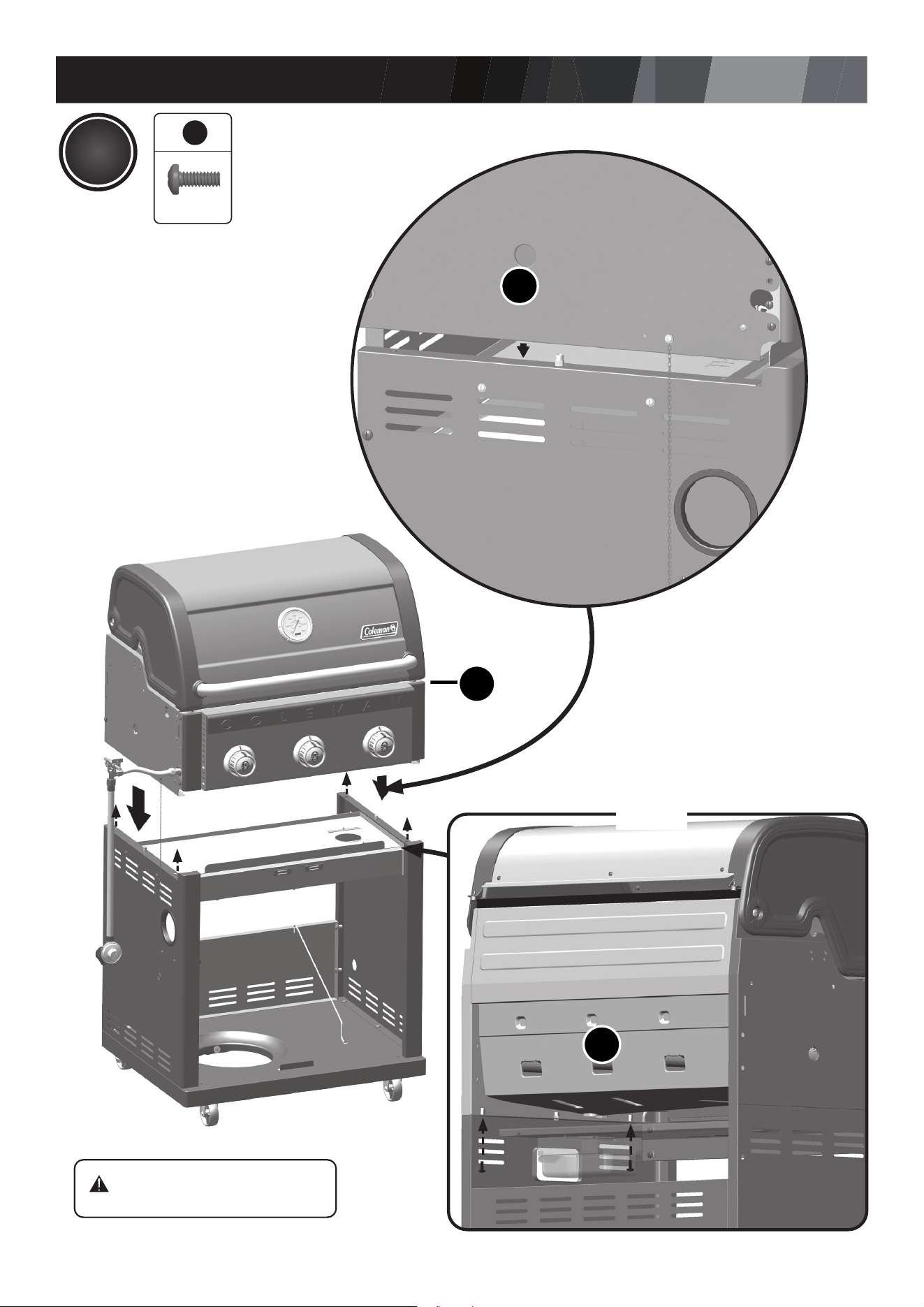
ASSEMBLY INSTRUCTIONS
13
7
BA
BA
BA
2X
6
2
X 4
WARNING:
WATCH YOUR HANDS!
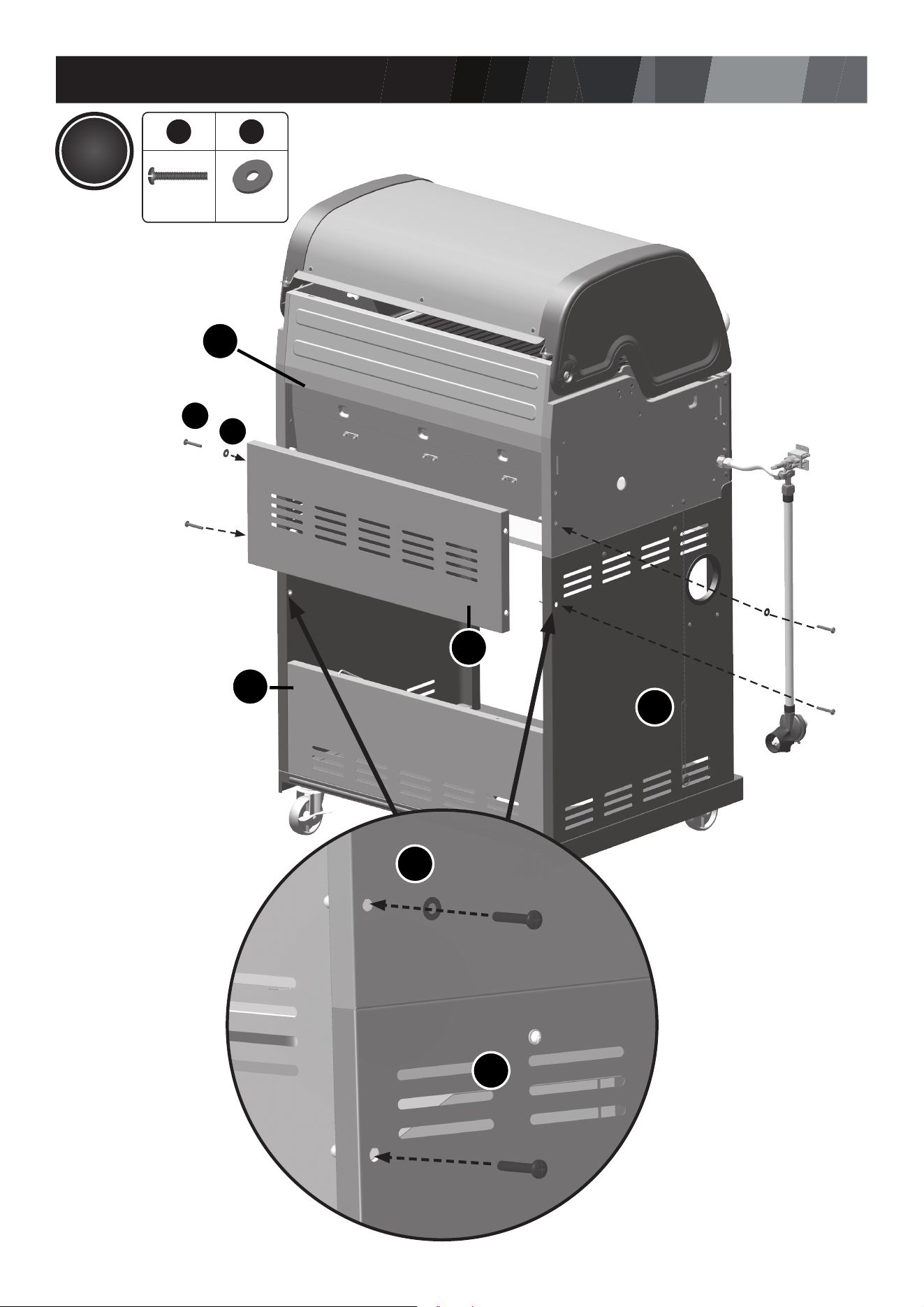
ASSEMBLY INSTRUCTIONS
14
CM
CN
EA
66
71
X 2X 4
EA
BA
BA
1
7
8
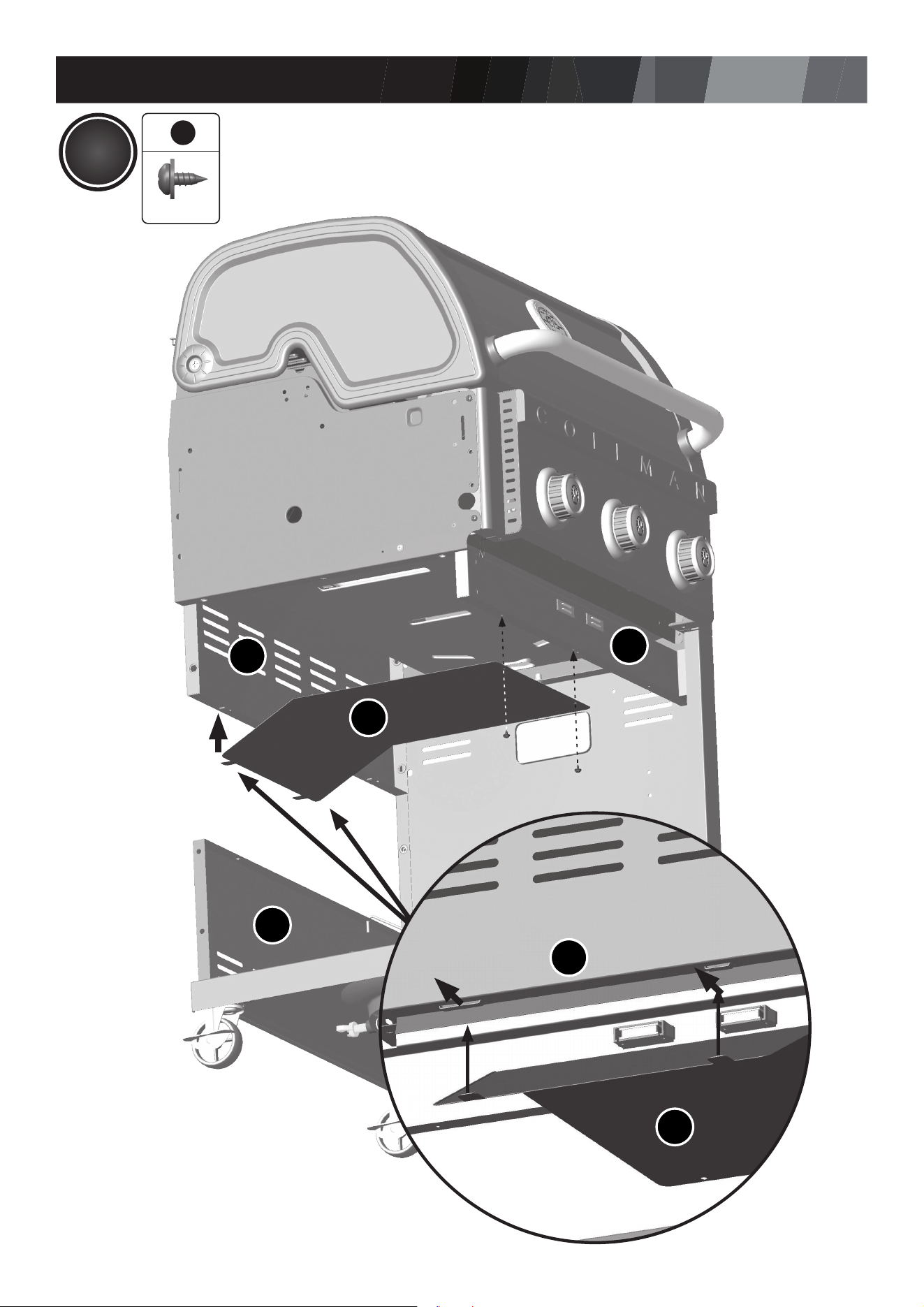
ASSEMBLY INSTRUCTIONS
15
CJ
CP
CN
6
6
X 2
CM
CP
CM
9
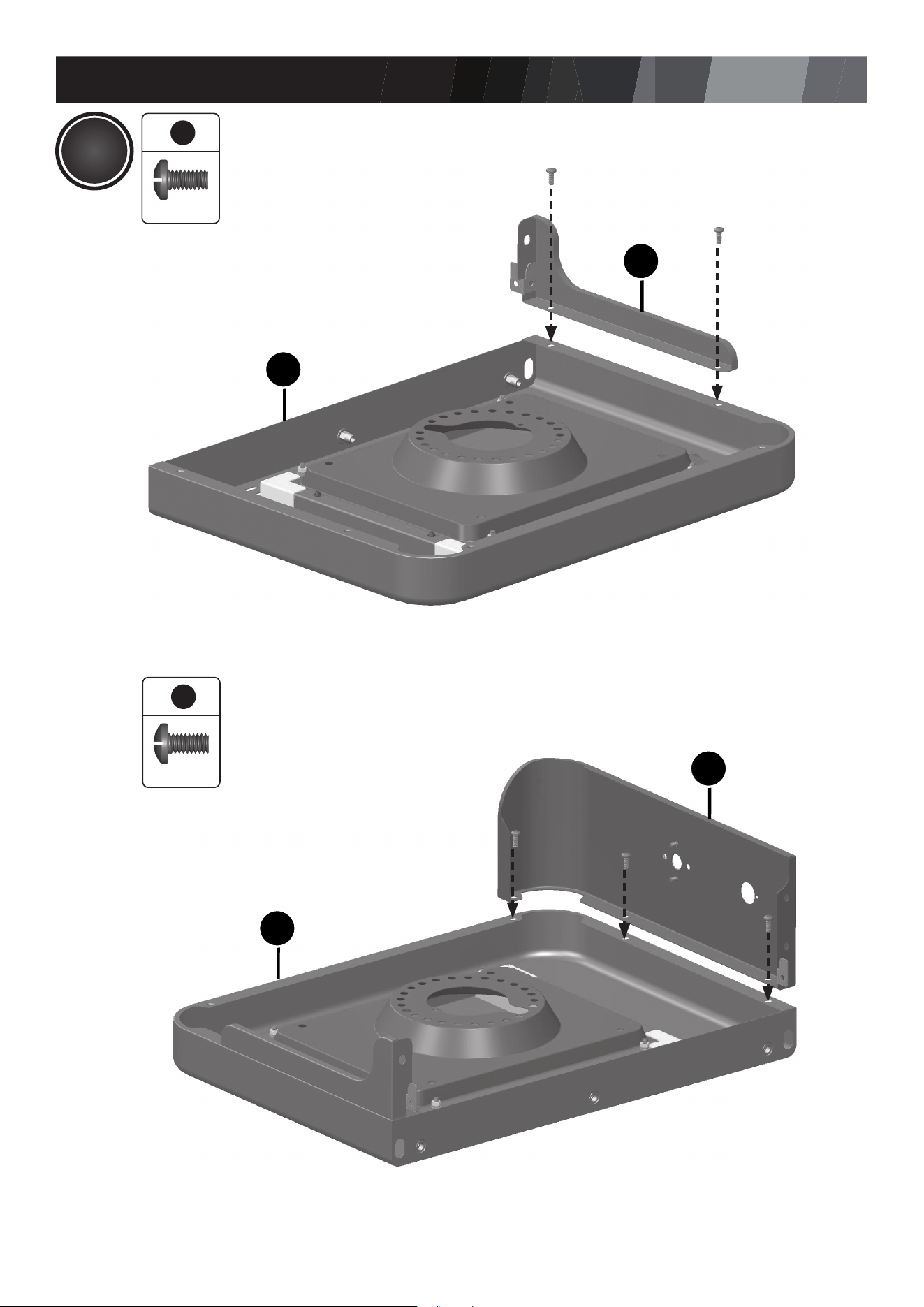
ASSEMBLY INSTRUCTIONS
16
DA
DA
DC
DB
A.
B.
6
6
3
3
X 3
X 2
10
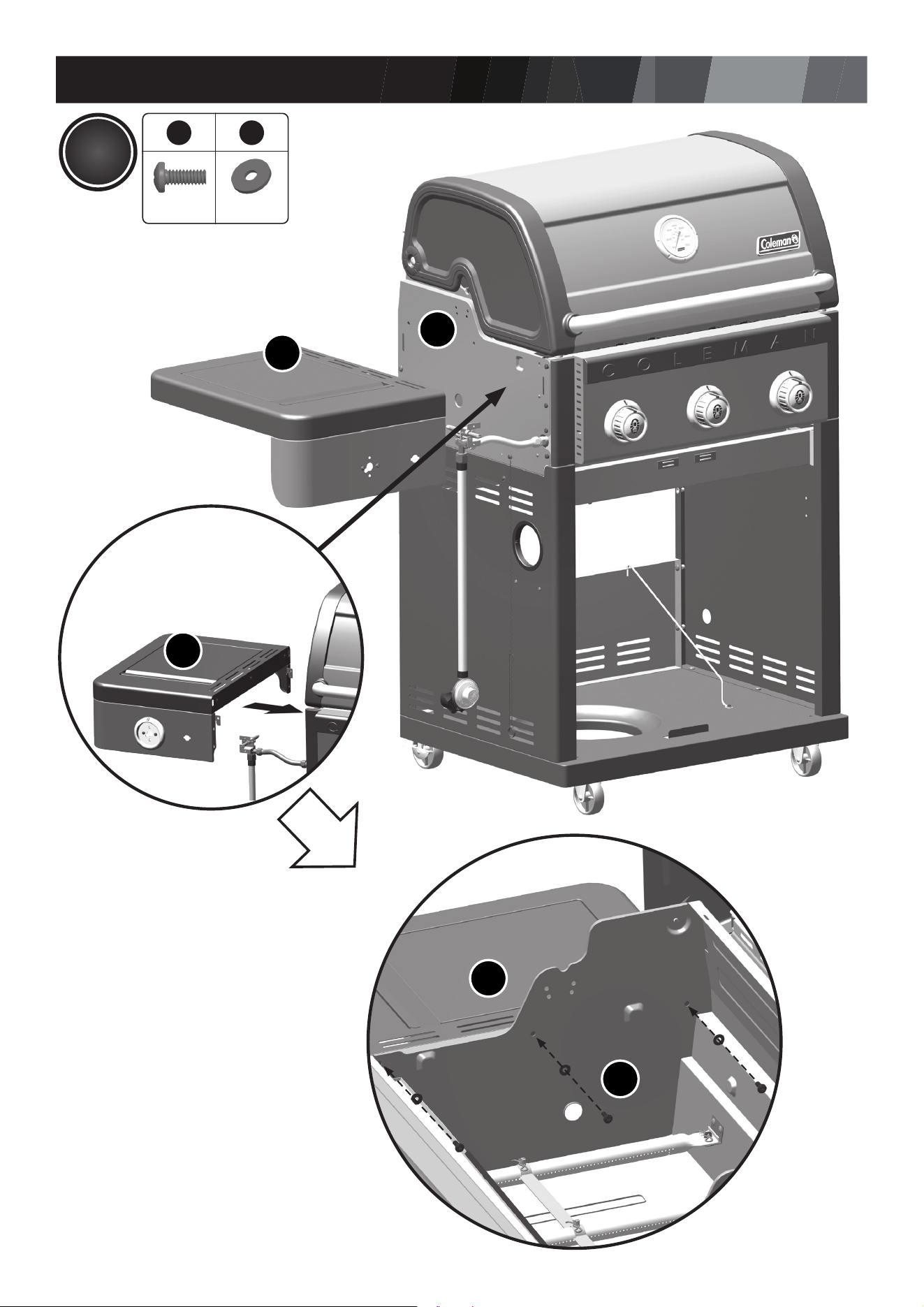
ASSEMBLY INSTRUCTIONS
17
DA
BA
A.
66
72
X 3X 3
TIP:
Ensure that the rubber side of the
rubberized washer makes contact
with the burner box.
B.
DA
DA
BA
11
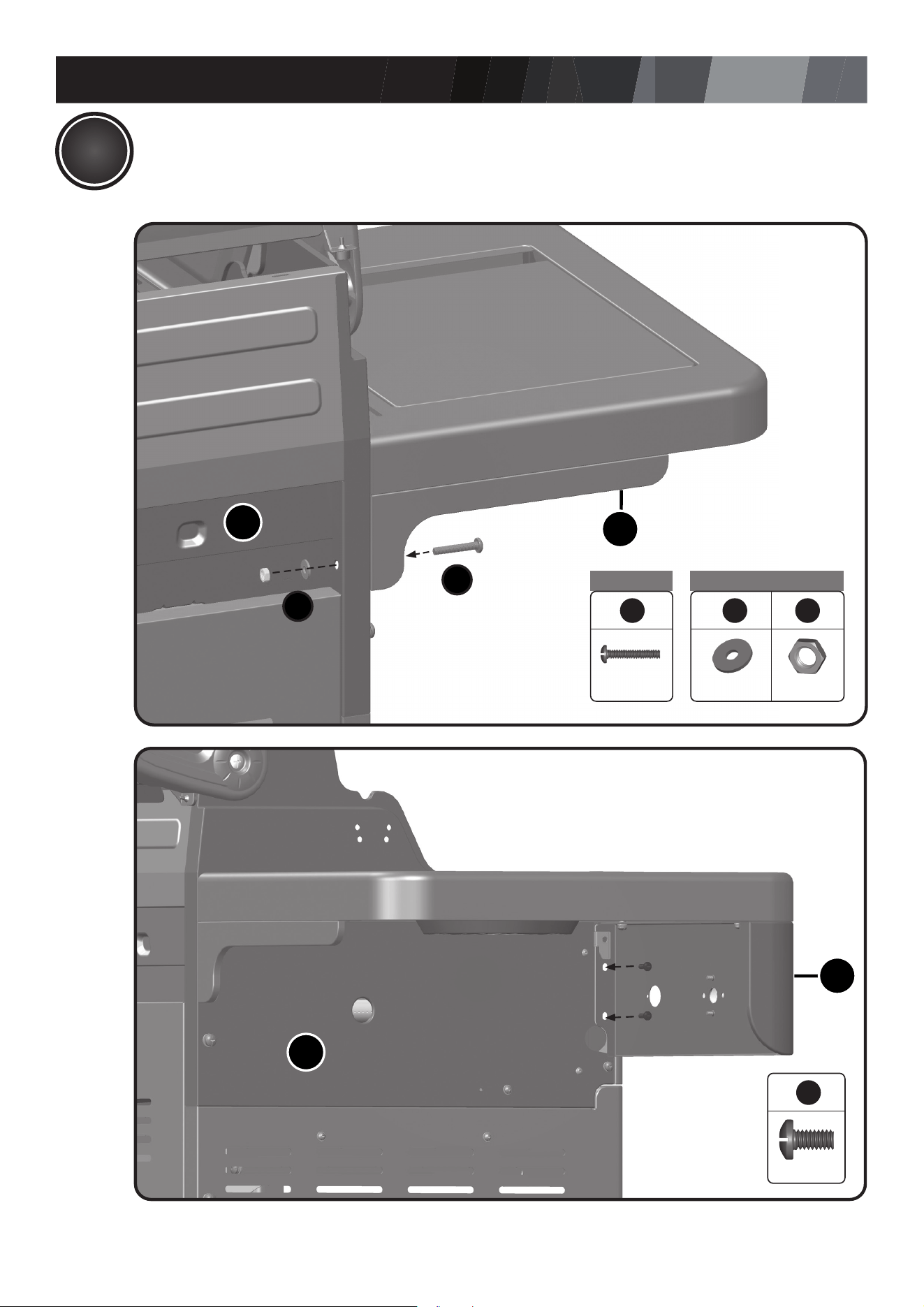
ASSEMBLY INSTRUCTIONS
18
11
C.
D.
DC
BA
A1 B2
6
871
X 1X 1X 1
A1
B2
BA
DB
6
3
X 2
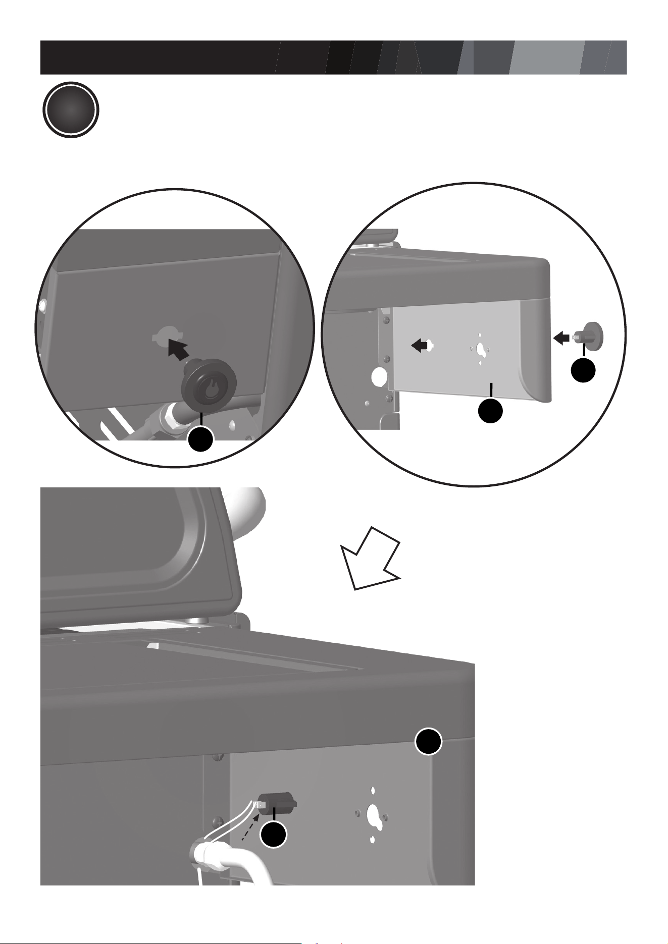
ASSEMBLY INSTRUCTIONS
19
11
DB
CE3
CE3
DB
E.
CE3
Front view
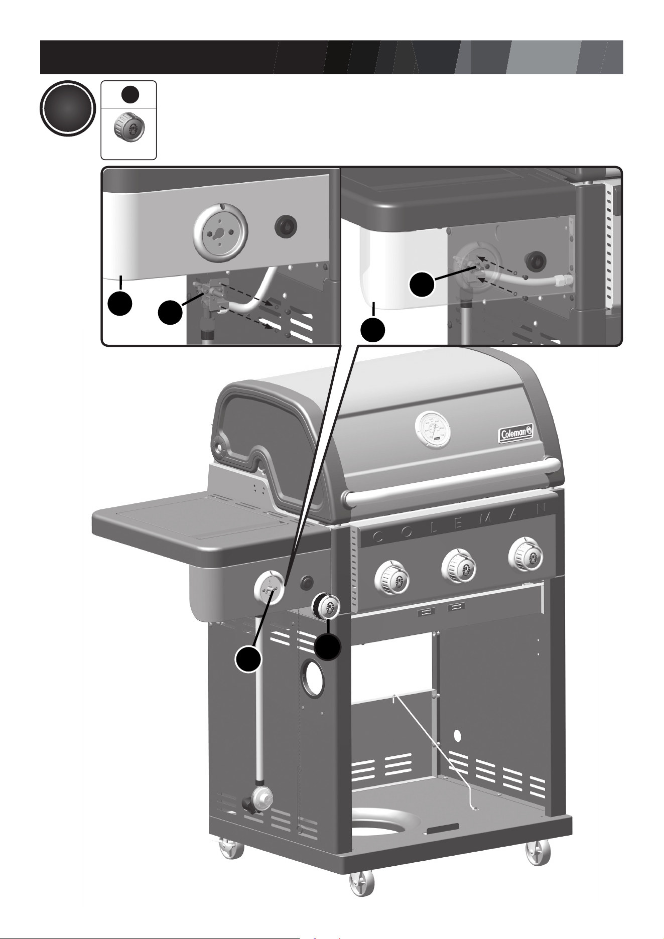
ASSEMBLY INSTRUCTIONS
20
12
DB
10
CC
CC
6
10
X 1
CC
DB
C.
A. B.
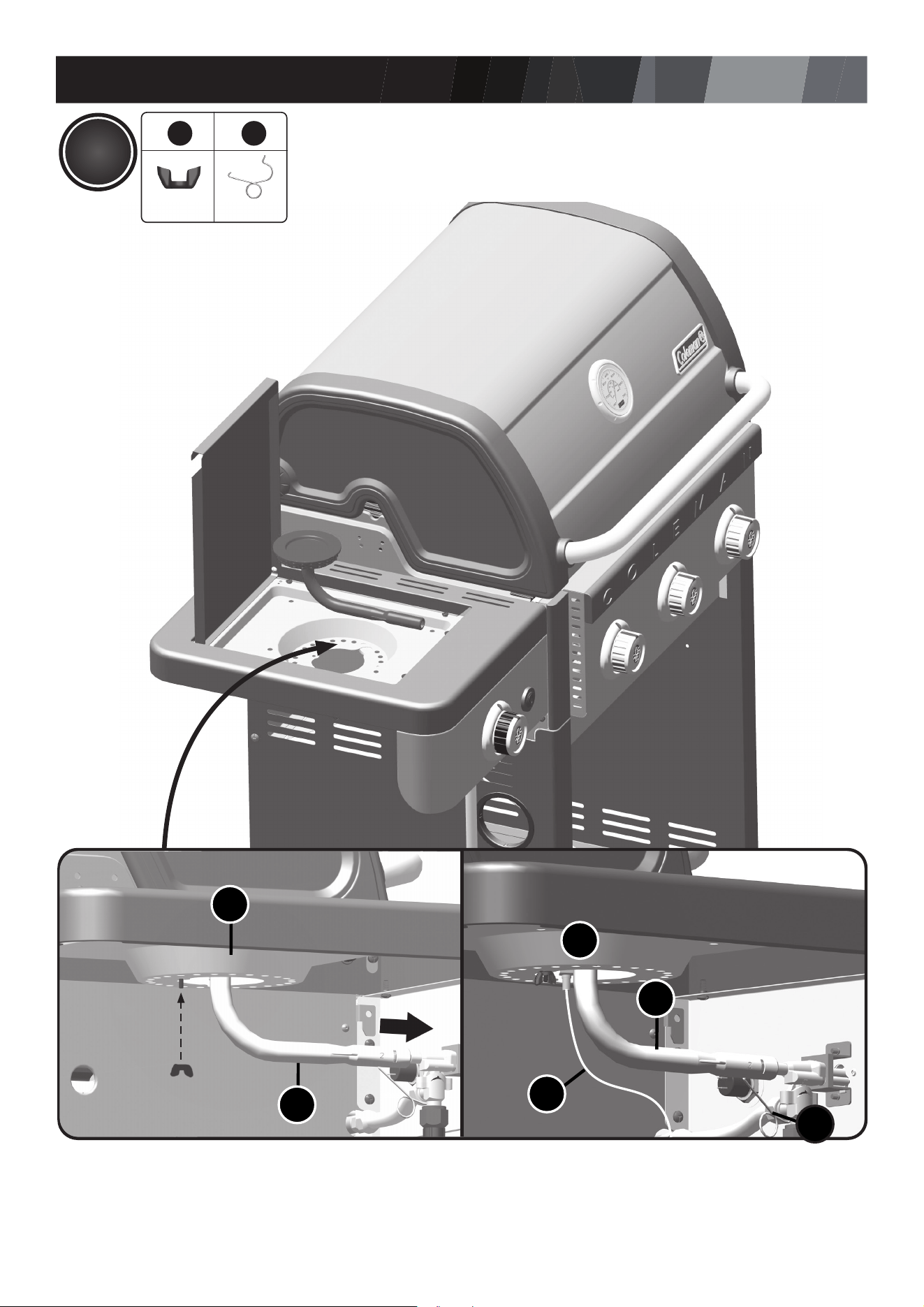
ASSEMBLY INSTRUCTIONS
21
12
DE
DD
DD
12
DE
E. F.
DF
D.
66
11
X 1
12
X 1

ASSEMBLY INSTRUCTIONS
22
12
H.
DH
ASSEMBLY INSTRUCTIONS
23
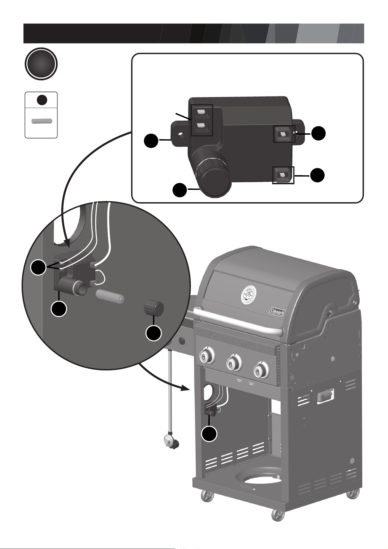
13
CE2
CE1
-
+
CE1
CE3
(CE3)
InstaStart
Button
Electronic Ignition Assembly:
The electrode set for main burner (CF), side stove (DF) and Instastart button (CE3) are found
under the control panel (CI) attached to the manifold (CA). Insert the electrode sets into the
electronic ignition (CE1)
CE1
CE2
CF
DF
14
X 1
ASSEMBLY INSTRUCTIONS
24
14
DI
DI
DJ
DK
6
3
X 5
ASSEMBLY INSTRUCTIONS
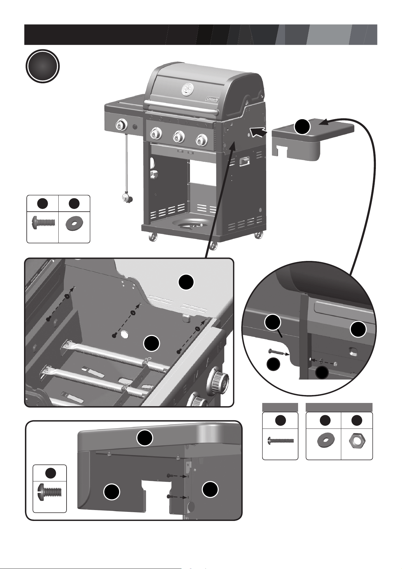
25
15
DI
6
3
X 2
BA
DJ
DI
66
72
X 3X 3
A1 B2
66 6
871
X 1X 1X 1
BA
DK
A1
B2
BA
DI
ASSEMBLY INSTRUCTIONS
26
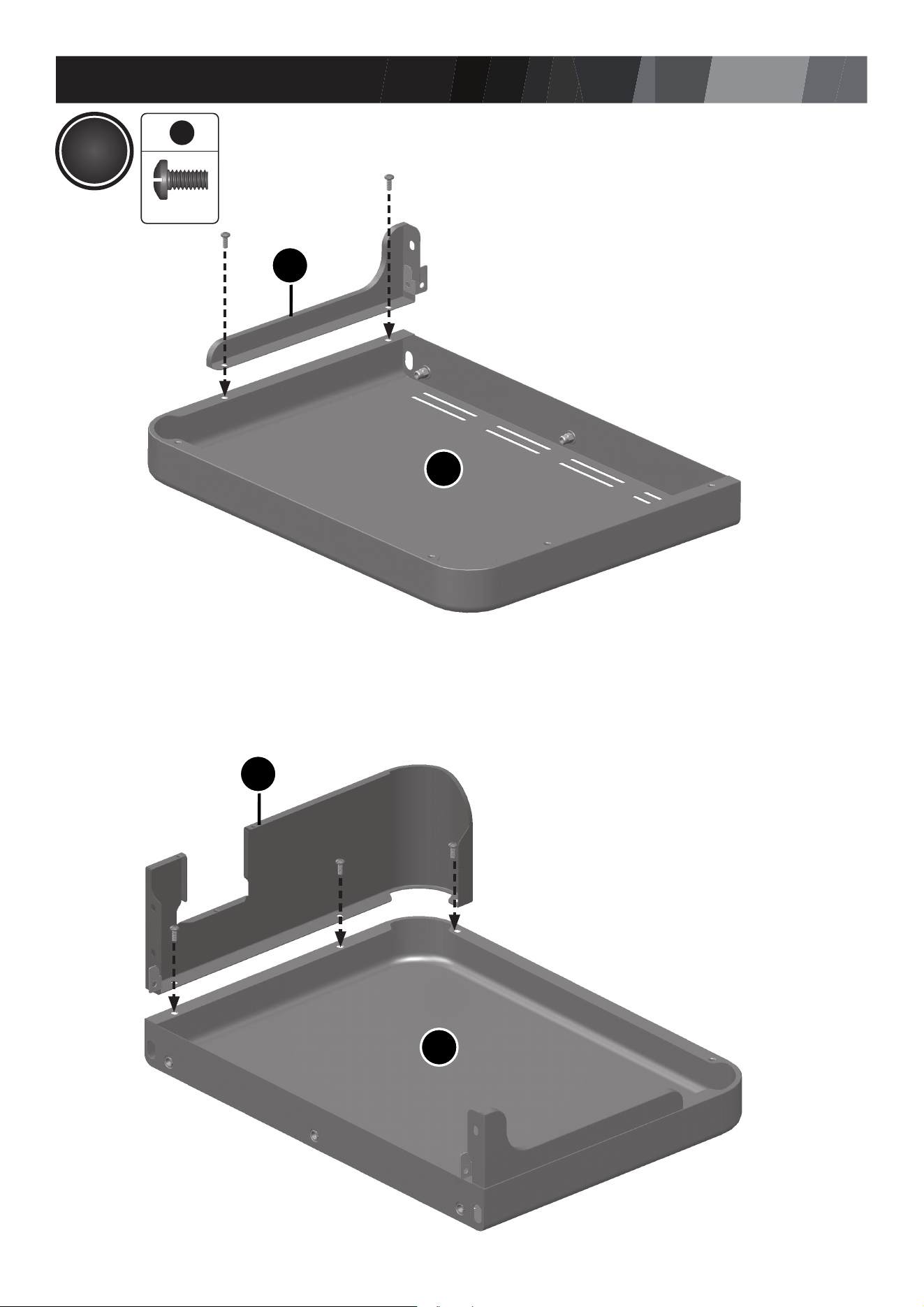
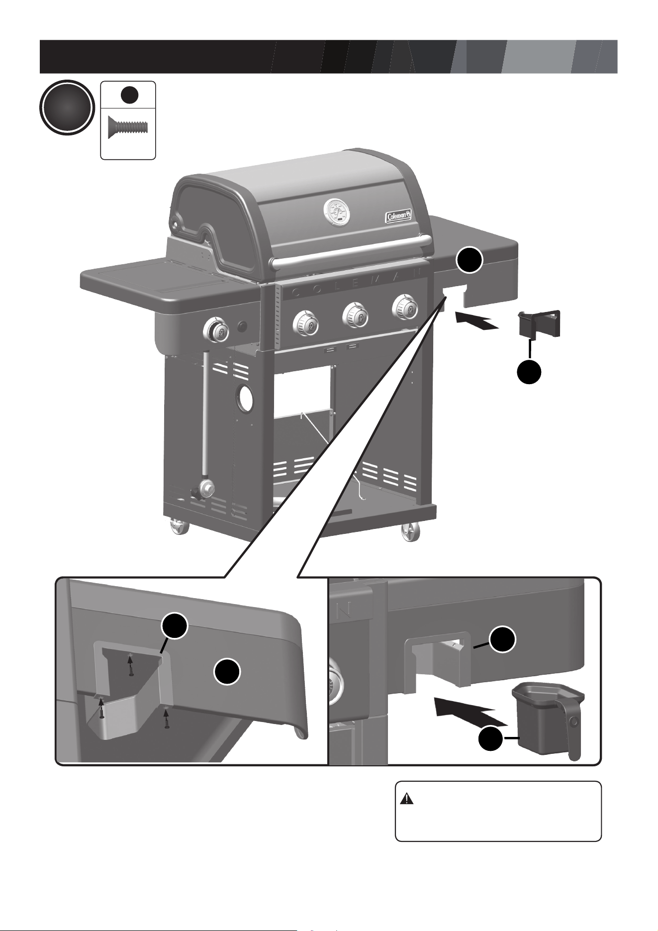
DL
DL
DM
DL
DJ
DJ
6
5
ATTENTION:
EMPTY GREASE CUP
AFTER EACH USE.
16
X 3
ASSEMBLY INSTRUCTIONS
27
17
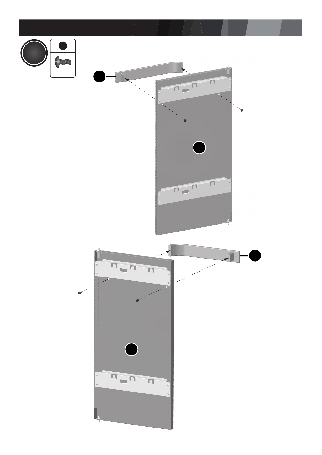
EE
EE
EC
ED
6
3
X 4
ASSEMBLY INSTRUCTIONS
28
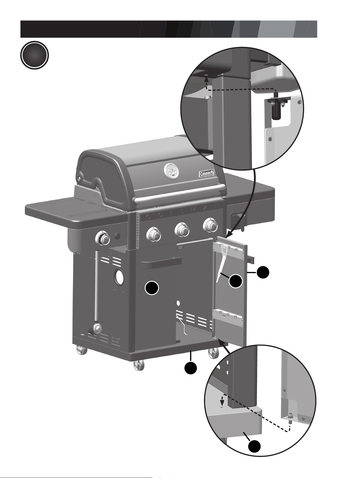
18
ED
BG
EF
EC
EF
ASSEMBLY INSTRUCTIONS
29
19
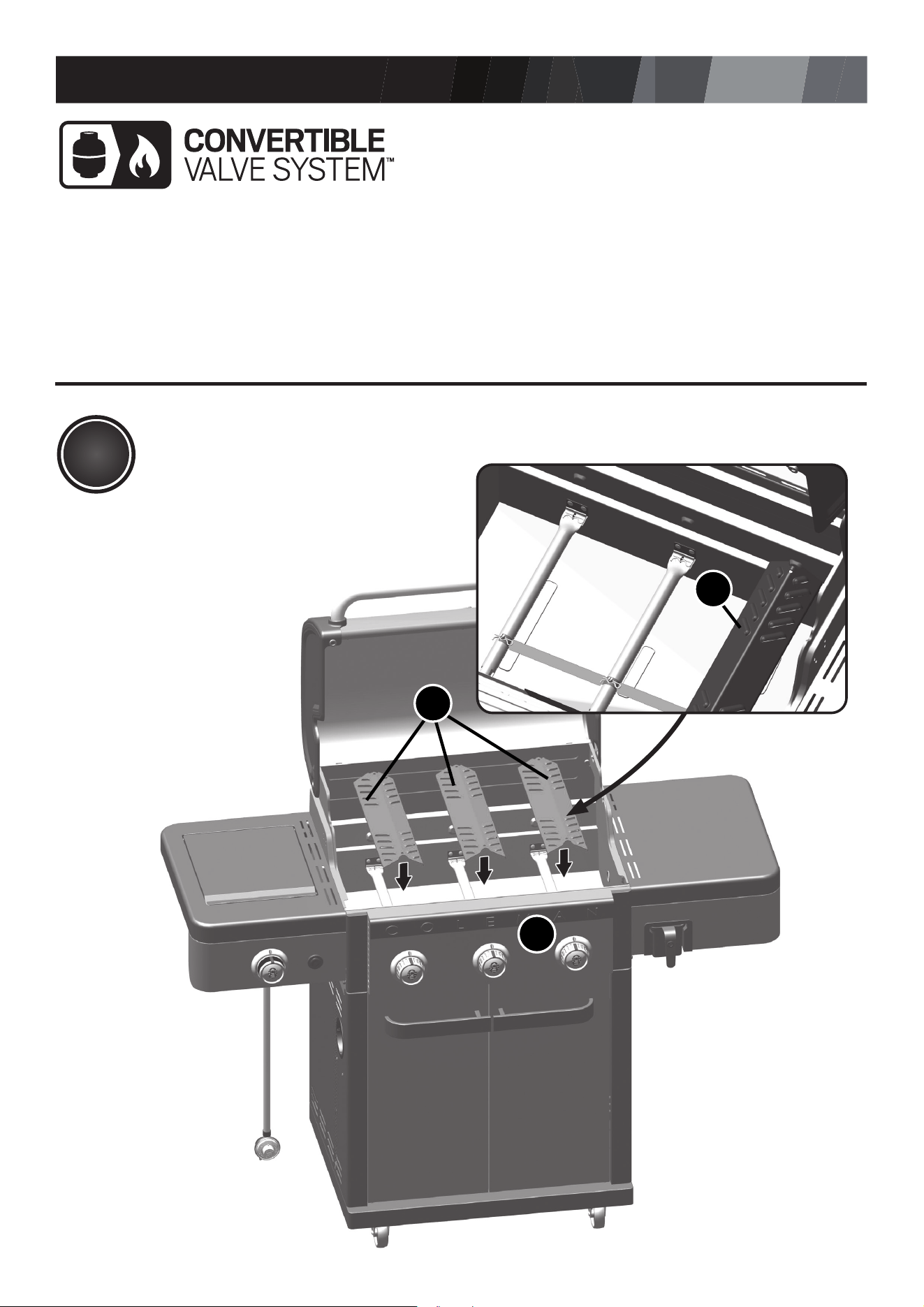
BA
BD
BD
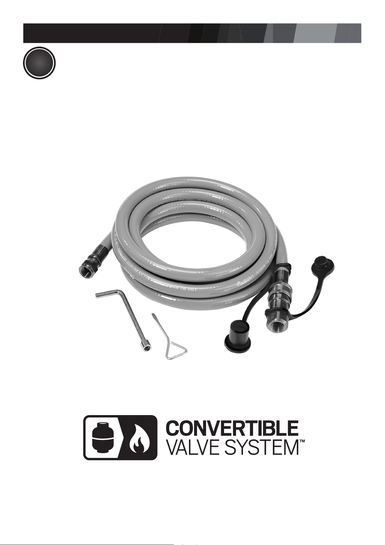
YOUR MODEL includes the CONVERTIBLE
VALVE SYSTEM™. If you would like
to convert your grill from PROPANE to
NATURAL GAS, the following kit is required
Convertible Valve System™ Natural Gas
Conversion Kit (Sold Separately).
Before completing steps 19 to 23, follow
the steps outlined in the CONVERTIBLE
VALVE SYSTEM™ instruction manual that
accompanied the kit.
ATTENTION:
ASSEMBLY INSTRUCTIONS
30
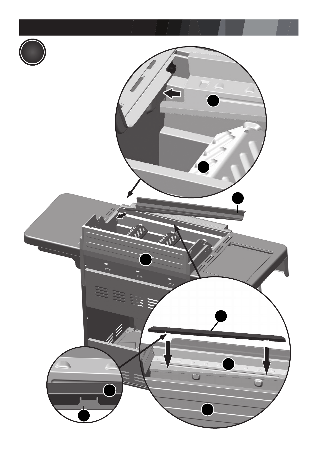
BE
BE
BA
BA
BE
BA
BJ
BJ
BE
20
ASSEMBLY INSTRUCTIONS
31
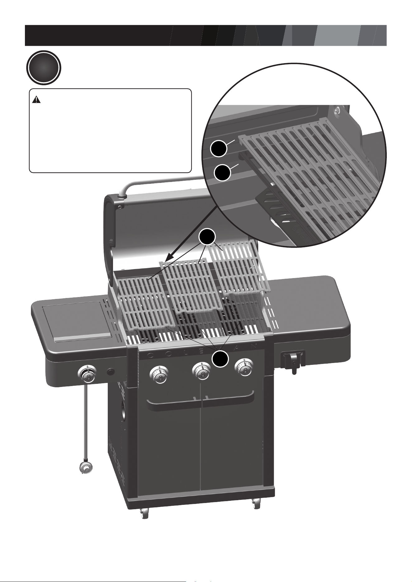
21
BF
BF
BK
BK
BK
ATTENTION:
STACK GRATES BEFORE
POSITIONING.
Upper Cooking Grate:
BF - Porcelain Cast Iron Cooking Grate
Lower Cooking Grate:
BK - Stamped Steel Cooking Grate
ASSEMBLY INSTRUCTIONS
32
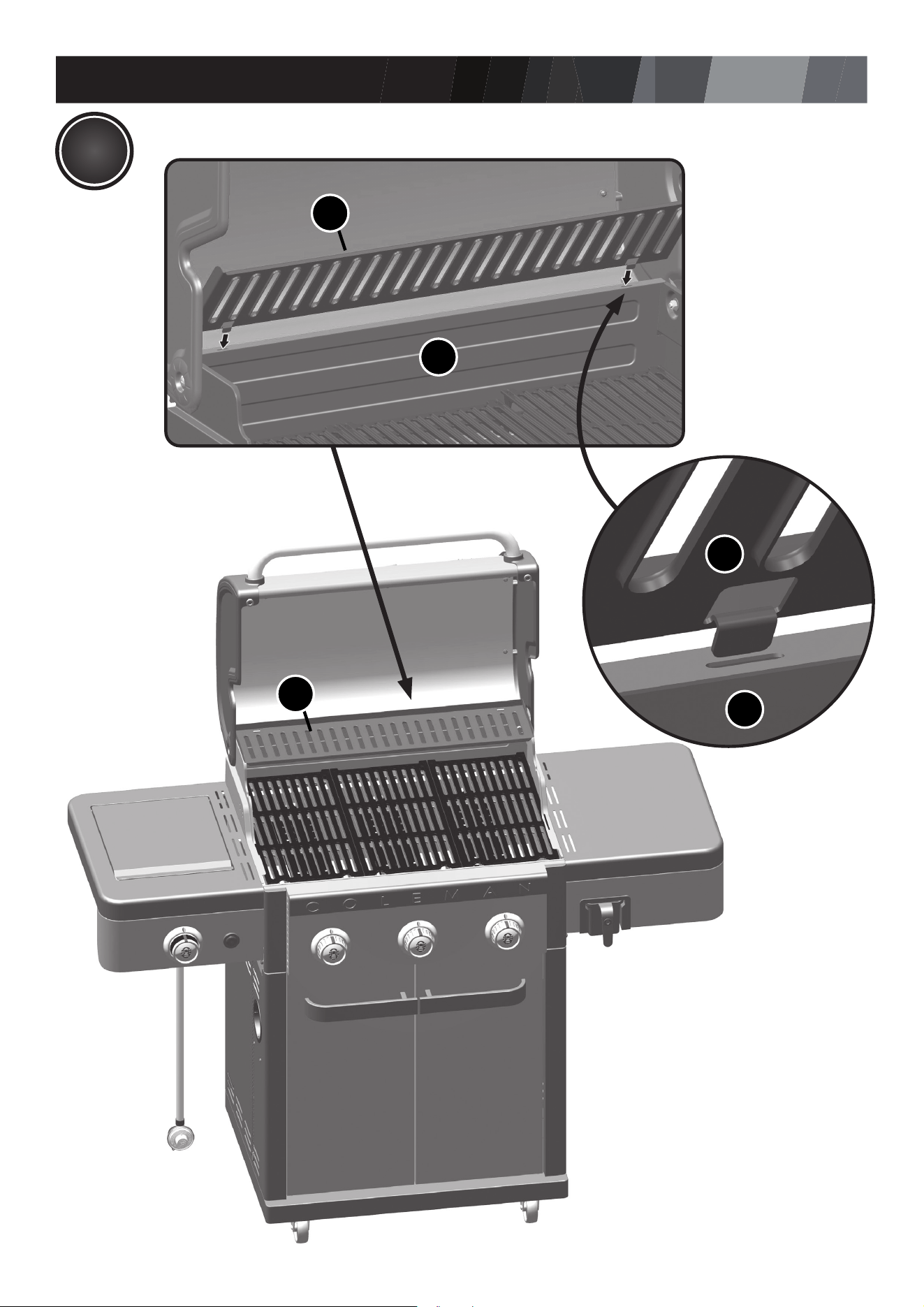
22
BH
BH
BA
BH
BA
ASSEMBLY INSTRUCTIONS
33
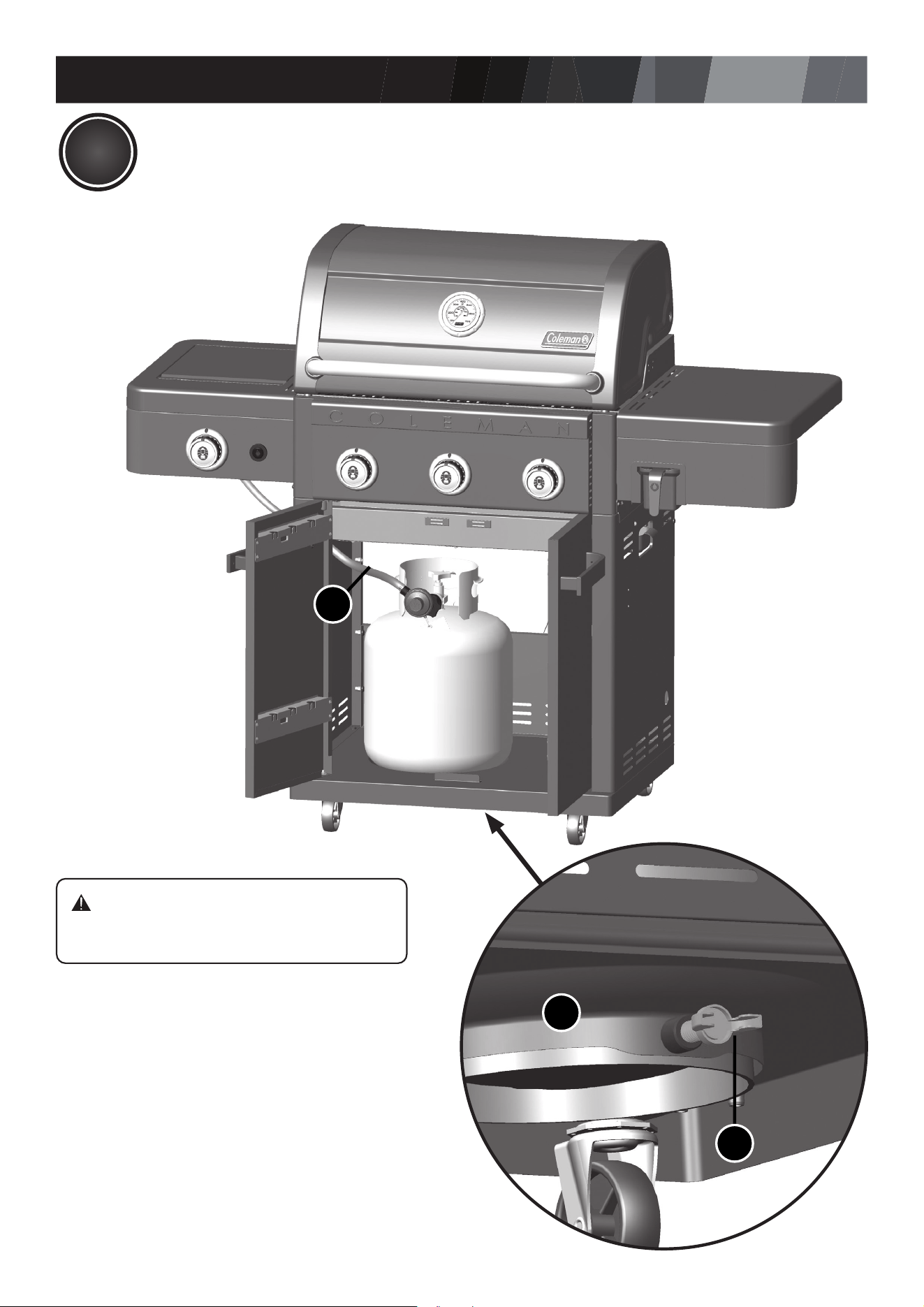
23
CB
ATTENTION:
DO NOT STORE EXTRA PROPANE
TANK WITHIN GRILL CART.
F4
EF
FOR PROPANE MODEL ONLY.
FOR NATURAL GAS MODEL, FOLLOW STEP 24.
ASSEMBLY INSTRUCTIONS
34
24
HOW TO CONVERT YOUR GRILL TO NATURAL GAS
This grill is sold propane-ready. To convert it to natural
gas, purchase the Coleman Convertible Valve System
Kit.
35
ADDITIONAL WARNINGS
POSITION YOUR GRILL
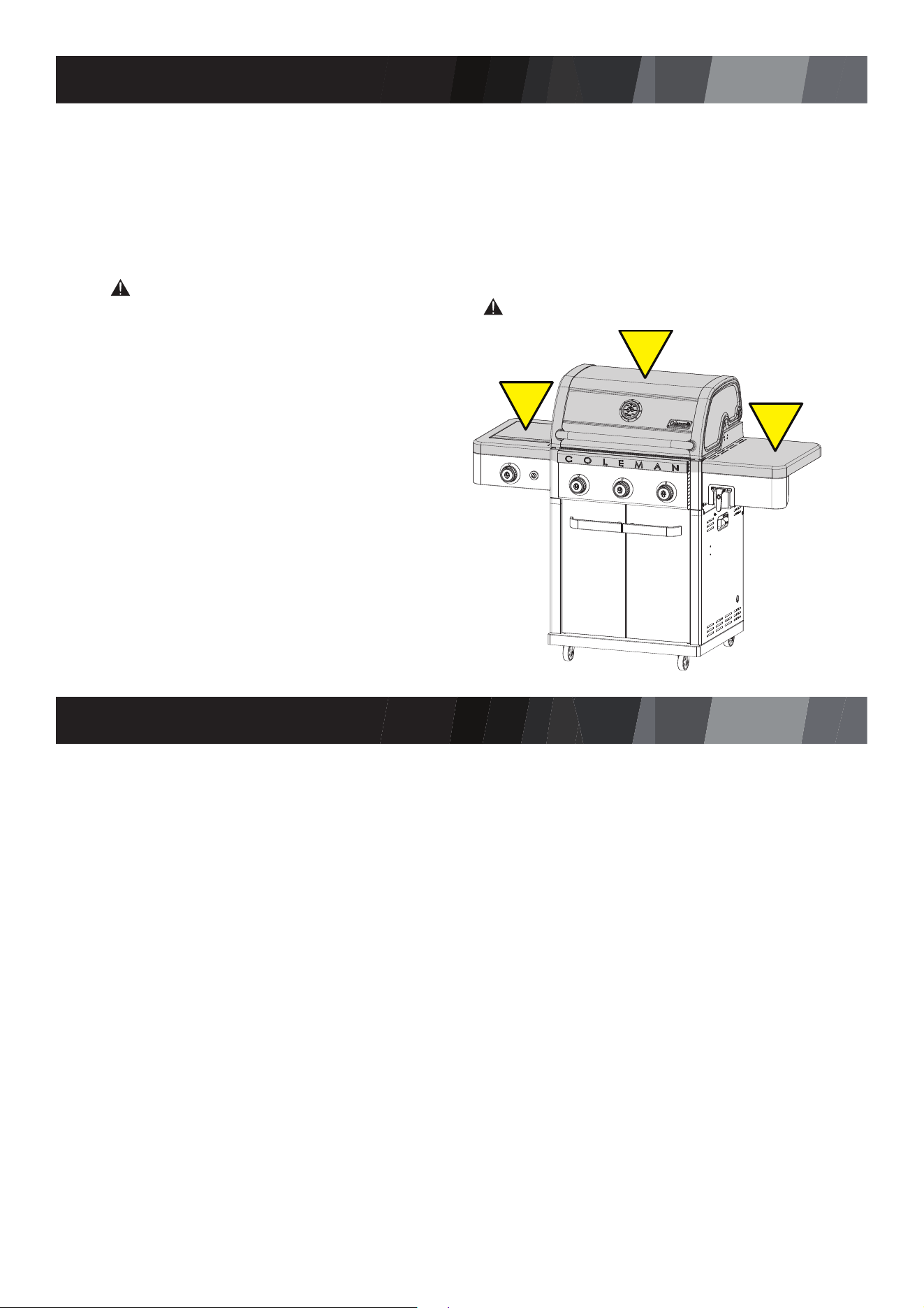
WARNING HOT SURFACES:
You have now completed the assembly of your Coleman® Revolution™ grill.
NEXT STEPS:
1. Position your Grill
2. Read Safe Use & Care Manual
3. Perform Grill Safety Check-list
WARNING:
FOR YOUR FAMILIES SAFETY,
DO NOT ATTEMPT TO LIGHT
THIS GRILL UNTIL YOU HAVE
REVIEWED PAGES 4-7 OF THE
COLEMAN® SAFE USE & CARE
MANUAL. ALL SAFETY AND LEAK
TESTS MUST BE PERFORMED
BY THE END USER, PRIOR TO
LIGHTING THIS GRILL.
Always conrm that this grill is not positioned under a combustible object
(e.g., an awning or umbrella) or in a covered area (e.g., porch or gazebo) before lighting it,
to prevent a possible re.
Always conrm that this grill is not positioned under the overhang of a house,
a garage or other structure before lighting it. An overhang will serve to deect
are-ups and radiate heat into the structure itself, which could result in a re.
Always conrm that this grill is positioned more than 36” (91.4cm) away from any
combustible materials or surfaces before lighting it, and that no gasoline or other volatile
substances are stored in the vicinity of this grill. The temperature of a grease re or of
the radiated heat might otherwise be sufcient to ignite nearby combustibles or volatile
substances. Do not position near windows, siding, or fencing.
Always locate the grill where there will be ample combustion and ventilation air, but
never position it in the direct path of a strong wind.
Level your grill for optimal performance of Flare-Free Technology™.
!
!
!
Licenced by BackHome Products LLC.
©2024 The Coleman Company, Inc.
Coleman
®
, and are registered trademarks of
The Coleman Company, Inc. used under license.