U.S. Solid® • 1200 E.55th Unit C, Cleveland, OH, 44103 • www.ussolid.com
800.209.4177
USS-MSV
MODELS
INSTALLATION AND
MAINTENANCE
MOTORIZED BALL VALVES
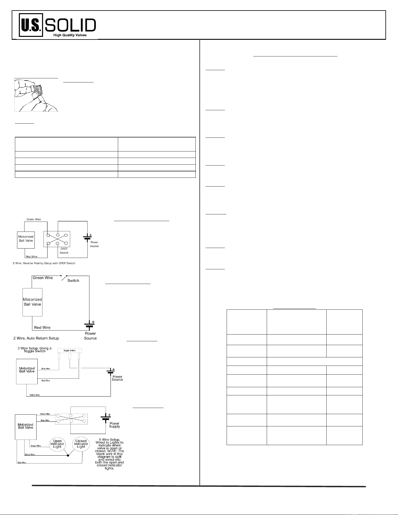
2 Wire Auto Return
The 2 wire auto return can be con-
nected directly to a simple On/Off
Switch. When the valve is energized
(by switching on), the valve will open.
It will remain open until the valve is
de-energized (by turning the switch
off, or due to loss of
power).
3 Wire Setup
The three wire setup shows
an example of wiring with
a toggle switch (SPDT). It is
important in this setup that
the Yellow Wire is connect-
ed to the (-) pole from the
power supply.
5 Wire Setup
In this 5 wire setup,
the motorized ball
valve is hooked up to a
DPDT switch. It is also
connected to 2 separate
indicator lights, so it is
simple to see if the valve
is open or closed, for
automation purposes.
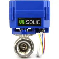
Thank you for purchasing your U.S. Solid Motorized Ball valve. We are
happy to have you as a customer! We want you to get the most out of
your new equipment, so we have included a few pointers to get you
started. Unfold this manual for simple wiring diagrams, schematics, and
specifications on your valve.
THREADING
U.S. Solid Valves follow National Standards for pipe
thread. In the U.S.A. we use NPT, while in England we
use BSPT. We recommend use of tefflon tape to ensure
seal of the NPT threading, as shown in the figure to the
left.
WIRING
There are 4 different wire setups with U.S. Solid Models. Please Note the
model number and wiring setup indicated in the table below.
Wiring Setup
Model
(USS-MSV000...)
2 Wires, Reverse Polarity 04, 05, 06, 12, 21, 22, 26
2 Wires, Auto-Return 07,08, 09, 10, 17, 18, 27
3 Wire Setup 01, 02, 03, 11, 19, 20, 25
5 Wires, Indicator Signal Setup 13, 14, 15, 16, 23, 24, 28
2 Wire Reverse Polarity
Once energized, Red (+) and
Green (-), the valve will open.
Once reversed, Red (-) and Green
(+), the valve will close. This can
be achieved with a DPDT switch
or similar arrangement.
FREQUENTLY ASKED QUESTIONS
1) Is my valve de-energized when fully open or fully closed?
Answer: For 2 wire reverse polarity models, and 3 wire models, yes. For
other models, there is a negligible amount of power used once fully open.
For the 5 wire model, there is energy used when closed, as well. This allows
the indicator lights to remain working. Check out the specifications sheet
for further questions.
2) Does the valve require water or air pressure to work?
Answer: No! One of the benefits of motorized ball valves is they can work
with little water pressure. This means a motorized ball valve can work even
with gravity fed arrangements.
3) Can this valve operate when partially open or closed?
Answer: For all but the Auto Return models, yes. You will have to carefully
monitor time and voltage to get it to stop at an exact point repeatedly,
though.
4) Can this valve be actuated manually?
Answer: No. Models depicted in this sheet are not designed to be opened
or closed manually.
5) Will this return to closed if power goes out?
Answer: If you purchased an Auto Return Model, then yes. All other models
will remain in the current position if power were to go out. If this is a
concern, we recommend getting one of the Auto-Return Models.
6) Can this valve be used outside?
Answer: The motorized ball valves all have a rating of IP65, which means
they can withstand spray from water. However, if permanently installed
outdoors, it is recommended that you enclose the motorized ball valve in
some protective housing.
7) Can this motorized ball valve be powered continuously?
Answer: Due to the power limiting features of these valves, they can be
hooked up to power non-stop without risk of overheating.
8) How does the threading work?
Answer: All of these motorized ball valves use NPT threading. This is the
most common type in the United States. When connecting the valve to other
piping, be sure to use some sort of thread sealant.
SPECIFICATIONS
Models:
USSMSV000...
01,02,03, 04, 05, 06,
07, 08, 09, 10, 11, 12,
17,18,19,20,21,22,
25,26,27
13, 14, 15, 16,
23, 24, 28
Torque 2 N m 6 N m
Open/Close
Time
3-5
Seconds
6-8
Seconds
Voltage
9V-24V DC or AC/DC
Max Power 2W 5W
IP Rating
(Casing)
IP65 IP65
Max Pressure 1.0Mpa 1.0Mpa
Temp. Range
for Flow
Medium
0°C to 90° C 0°C to 100° C
Ambient Temp.
Range
-10°C to 40° C -5°C to 40° C
De-Energized
Fully When
Open or Closed
Yes No
The following wiring diagrams are only examples. There are many other
possible ways to wire these ball valves. Before making any electrical con-
nections, make sure the power is off.
Models with AC/DC voltage: 01/02/03/07/08/09/10
/11/17/18/19/20/25/27
WIRING
SCHEMATICS
MOTORIZED BALL VALVES
MSV
MODELS
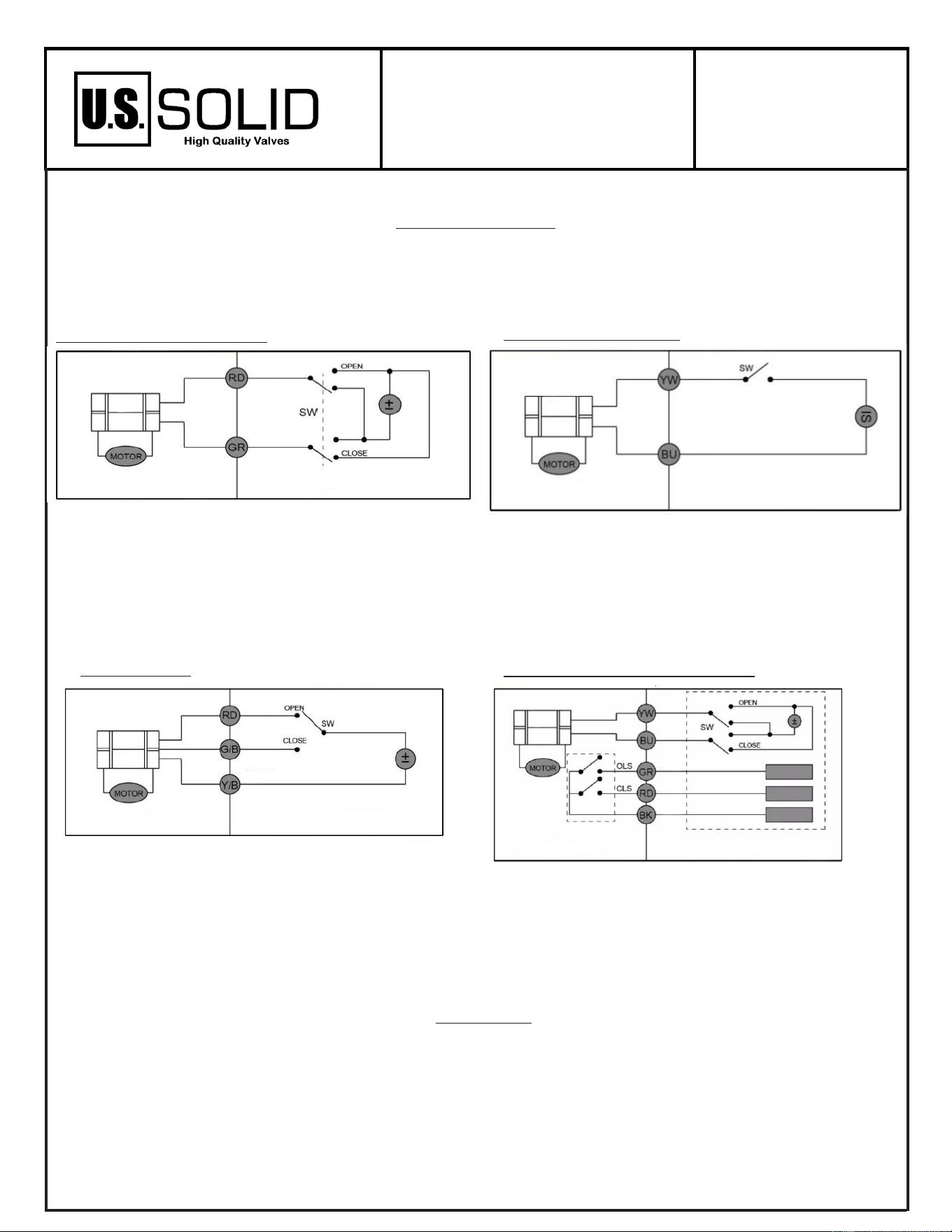
Wiring Schematics
Included below are the wiring schematics for all four wiring setups included in this information
sheet. These are a more formal presentation of wiring options for your valve. Be aware, there are
many possible ways to wire your motorized ball valve.
WARRANTY
All U.S. Solid motorized ball valves come with a one year warranty.
We realize that other questions or concerns may arise during the installation and operation of your
valve. Please contact us or visit our website for help.
Phone: 800-209-4177
Email: ser[email protected]
Website: www.ussolid.com
1. When the Switch is set to open, the valve fully opens. Once in
this state, the valve is de-energized (power consumption is zero).
This occurs when the Red Wire is connected to the (+) pole, and
the Green Wire is connected to the (-) pole.
2. When the switch is set to close, the valve will fully close. Once
in this state, the valve is de-energized (power consumption is
zero) This occurs when the Red Wire is connected to the (-) pole
and the Green Wire is connected to the (+) pole.
3. In case of power loss, valve will remain in its current state.
2 Wires, Reverse Polarity
1. When the circuit is closed (switch connecting the valve is on),
the valve will open, and remain open. Once open, power con-
sumption is nominal.
2. When the circuit is open (switch connecting the valve is off or
power is lost), the valve will close. Once in this state, the valve is
fully de-energized (power consumption is zero).
2 Wires, Auto Return
1. Yellow Wire must be connected to the (-) pole of the power
source.
2. When switch is set to open, valve will fully open. Once in this
state, the valve is de-energized (power consumption is zero).
3. When switch is set to close, valve will fully close. Once in this
state, the valve is de-energized (power consumption is zero).
4. In case of power loss, valve will remain in its current state.
3 Wire Setup
1. When switch is set to open, the valve will fully open. Once fully
open, the valve will largely de-energize. The Open Limited Signal
will be energized, indicating that the valve is fully open.
2. When switch is set to close, the valve will fully close. Once fully
closed, the valve will largely de-energize. The Closed Limited
Signal will be energized, indicating that the valve is fully closed.
3. In case of power loss, valve will remain in its current state.
5 Wires with Indicators Setup