1
When installing this accessory directly below another unit, only
install with Fire Magic built-in products.
It is recommended that silicone caulking (not supplied) is
applied around the back of the unit's trim before installing into
the opening.
This unit must be installed per this instruction.
PREPARE FOR INSTALLATION
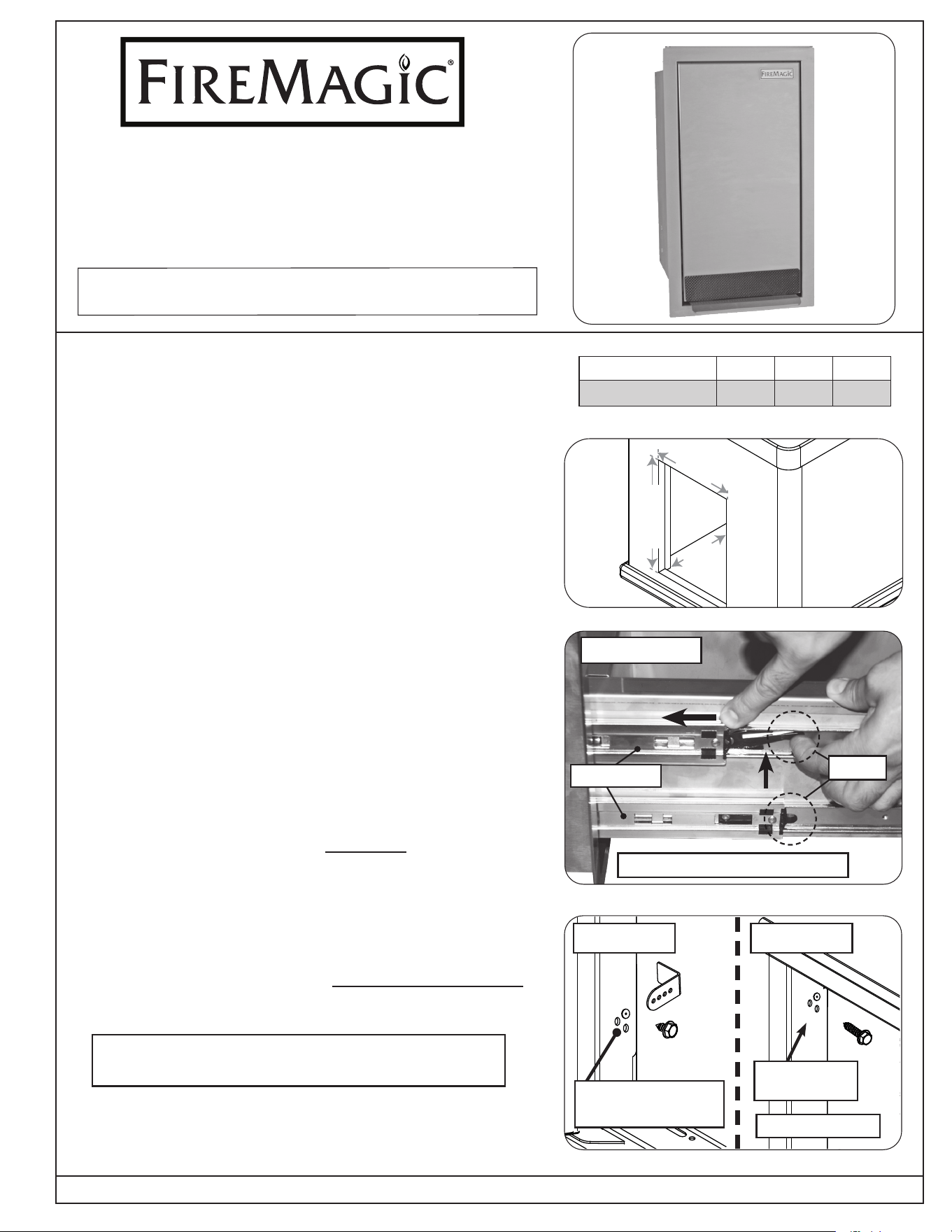
1. Create the appropriate cutout in your enclosure as specied
for your model number. See Table 1 and Fig. 1-1.
2. Remove all packaging and the protective coating from
the accessory.
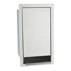
3. This trash container features a foot-activated pedal for
hands free disposal. To open, step onto the pedal to open
trash container. Remove the bin.
4. Release the door from the door slides by pressing the 2
black levers up on the left side and down on the right side
(with the levers pressed, the door slides will need to be
pushed back to unlock.) See Fig. 1-2. After all slides are
unlocked, pull the door o completely.
Note: To remove door, it may require a second person
to hold the door frame into place.
5. Insert the accessory's housing completely into the opening.
Ensure it is ush against the exterior wall.
6. Install the hardware kit as applicable to your enclosure.
See Fig. 1-3. This kit can be installed using two methods.
Find your preferred method in the installation section on
the next page.
Important: When installing in a Fire Magic GFRC Island,
this kit is required to be used with installation.
Fig. 1-2 Door removal
Fig. 1-3 Installation methods
Method A Method B
No bracket needed
Mark and drill
hole
Insert bracket between
frame and wall
REV 2 -B- 2605221320
L-C2-322
ROBERT H. PETERSON CO. • 14724 East Proctor Avenue • City of Industry, CA 91746
Fig. 1-1 Orientation
INSTALLER: Leave these instructions with consumer.
CONSUMER: Retain for future reference.
BUILT-IN
TRASH CONTAINER
Model #53825-T
Table 1 Cutout dimensions table
Model # Height Width Depth
53825-T 24" 12
3
/
4"
20"
WIDTH
H
E
I
G
H
T
DEPTH
Continue to the following page for installation
Left side shown
(Push levers down on right side)
Door slides
Levers
2
INSTALLATION METHODS
Method A: Brackets
Note: This method requires access to the interior of the
enclosure. If the countertop cannot be removed
to install the brackets, an access door must be
available to reach the interior.
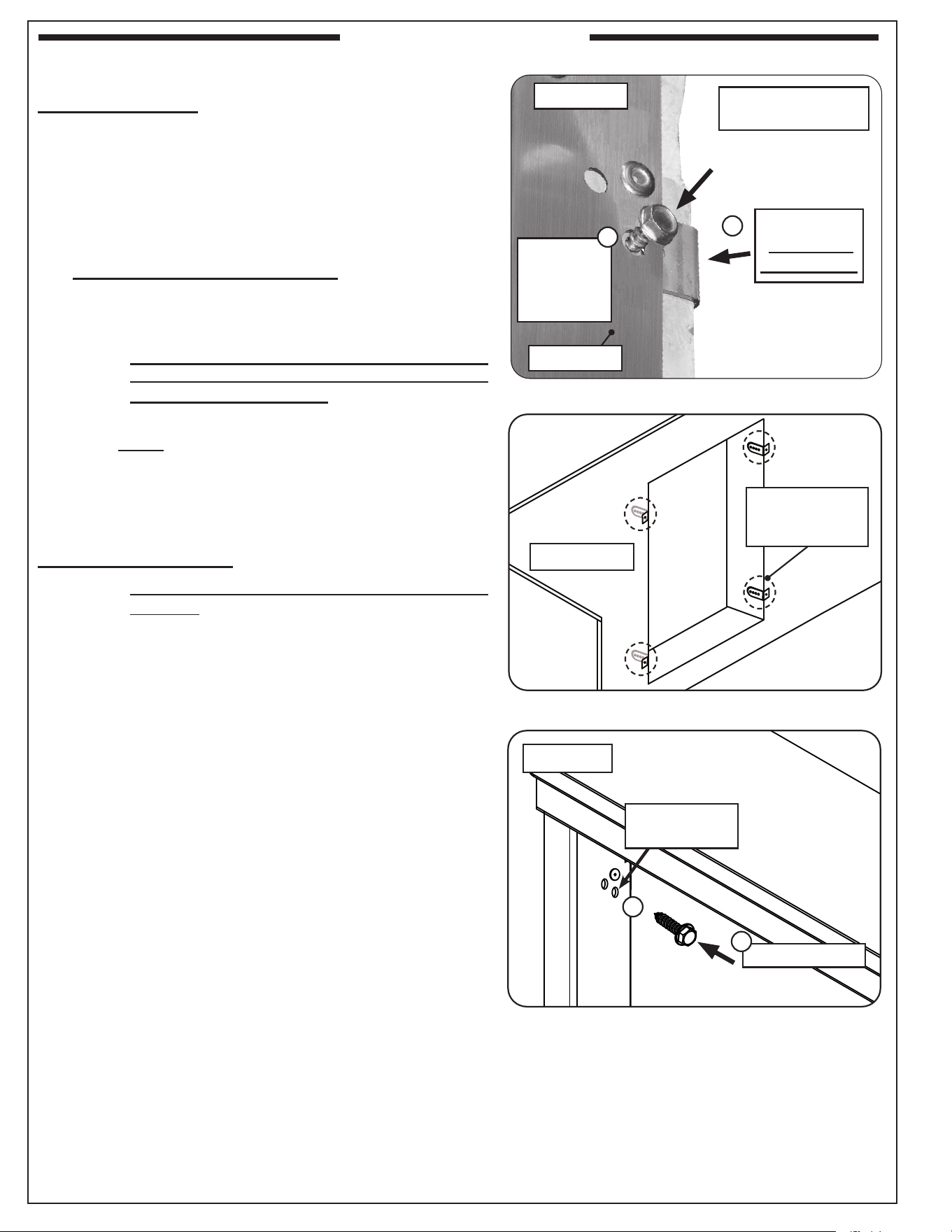
1. Use the 4 open holes closest to the interior on left and
right sides of the frame (see Fig. 2-1). Reach from within
the enclosure and insert a bracket where a cutout exists,
between the wall and door frame. See Fig. 2-1, A.
Note: Installation may require a second person to
hold the bracket against the wall from within the
enclosure.
Note: The bracket ange should be oriented away
from the frame and rest against the interior
enclosure wall (Fig. 2-2).
2. While holding the rear of the bracket and the front of the
frame rmly against the concrete wall, align a bracket hole
to the frame's hole cutout and insert a supplied short hex
screw. Tighten the hex screw with a power drill and
5
/16"
hex driver (see Fig. 2-1, B). DO NOT OVERTIGHTEN.
3. Repeat this process for the remaining brackets.
Method B: Long Screws
Note: This method does not require the use of the
brackets.
1. Use the 4 open holes closest to the interior on left and
right sides of the frame (see Fig. 2-2). Mark the holes
as needed.
2. Drill pilot holes for each screw. See Fig. 2-2, A. It is
recommended to use a #21 drill bit (0.159") to drill pilot
holes.
Note: The pilot hole depth must accommodate the
length of the long screw.
3. Insert the frame into the cutout and position to the pilot
holes.
4. Insert a long hex screw and tighten with the power
drill and
5
/16" hex driver (see Fig. 2-2, B). DO NOT
OVERTIGHTEN.
5. Repeat this process from the remaining screws.
Fig. 2-1 Method A install detail
Insert bracket
between the
wall and frame
A
Fig. 2-2 Method B install detail
Method B
Mark and drill
hole
Fasten to frame
A
B
Fig. 2-2 Bracket ange detail
Align to
bracket hole
and insert
short screw
(Accessory housing
removed for clarity)
Method A
Door frame
(Interior wall)
Bracket ange
against interior
enclosure wall
B
REV 2 -B- 2605221320
L-C2-322
INSTALLATION (cont.)
3
INSTALL REMAINING FASTENERS
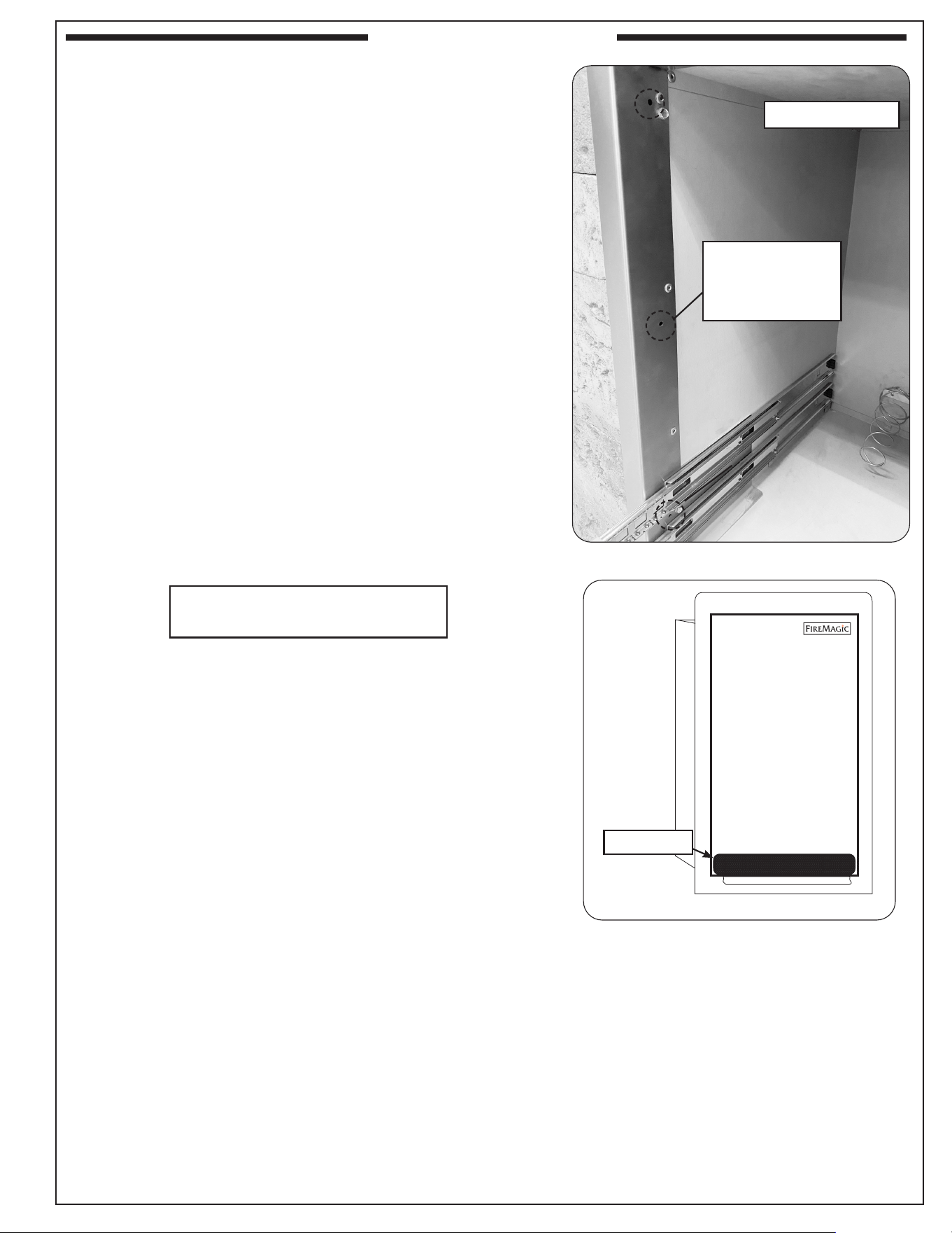
1. Locate the 3 screw holes found on each of the left and
right sides of the accessory frame (see Fig. 3-1).
2. Secure the accessory using a
1
/
8
" by
3
/
4
" fastening screws
(not supplied) that are appropriate for the enclosure
framework. DO NOT OVERTIGHTEN.
REATTACH DOOR & BIN
1. Reattach the door. Extend the door slides out completely
and align the door into the slides, push the door closed.
2. Open the door to verify it has locked in place. Replace
the bin.
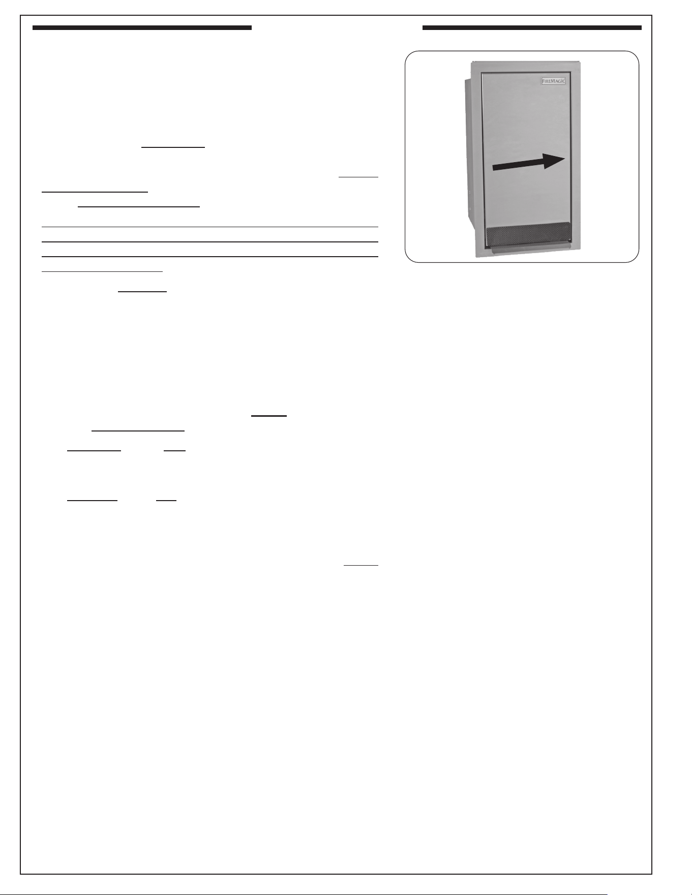
KICK GUARD
To help protect the bottom of your trash container during
foot-pedal operation, an optional kick guard is included. If
desired, follow the steps below for installation:
Note: The kick guard is designed for permanent installation.
1. Clean the area of the location for the kick guard.
2. Peel o the backing from the kick guard and apply it to
the bottom of the door (as shown Fig. 3-2).
Fig. 3-1 Fasten side walls of frame
®
Fig. 3-2 Attach kick guard (if desired)
Left side shown
Use (3) screws to
fasten frame to
enclosure on each
side (not supplied)
REV 2 -B- 2605221320
L-C2-322
INSTALLATION (cont.)
Kick guard
Continue to the next page
for care & cleaning
4
REV 2 -B- 2605221320
L-C2-322
By following these recommendations, you will enjoy the beauty
and convenience of your unit for many years to come.
The trash should be emptied regularly.
STAINLESS STEEL
As needed, use a grill cleaner (or a soapy water solution) and
a clean cloth to remove grease and dirt from the outside of the
unit. For tough deposits, a copper pad can be used. Always
wipe with the grain. Rinse and dry completely. Then follow up
with a stainless steel cleaner and a clean cloth.
If this routine cleaning is not performed, the stainless steel
may become dull and develop surface rust (due to use and
atmospheric conditions). If left uncleaned, signicant damage
and pitting may occur.
Important: DO NOT use steel wool, any other metal tools,
or any other cleaners/chemicals to clean the
exterior other than recommended above. Such
items promote rust.
When this unit is installed in a corrosive environment such
as near the ocean (salt air), poolside (chlorine and/or pool
chemicals) or any other location with exposure to high salt/
chloride content or corrosive chemicals/solutions, it will be
more susceptible to corrosion and MUST be maintained/
cleaned more frequently.
• DO NOT store any corrosive chemicals (chlorine,
hydrochloric acid, fertilizer, etc.) near your stainless steel
unit.
• DO NOT allow any corrosive materials (masonry dust,
debris, etc.) to settle on your stainless steel unit.
• These environments, chemicals, and materials may
cause the 304 stainless steel to develop surface rust and
consequently pitting. Under these conditions the unit MUST
be cleaned at least monthly. Inspect your unit often and
clean accordingly.
CARE & CLEANING
Fig. 4-1 Wipe with grain
Wipe with grain

5
NOTES PAGE
Please use this page to record any information that you may want to have at hand.

6
R.H. Peterson Co. • 14724 East Proctor Avenue • City of Industry, CA 91746
A COPY OF YOUR SALES SLIP FOR PROOF OF PURCHASE IS REQUIRED
This warranty applies to the original purchaser for products which are installed in the United States or Canada and which are operated and maintained as
intended for single family residential usage (if the unit is installed in a commercial / multi-user setting, a separate Commercial / Multi-User Limited Warranty
applies and is available from RHP). This warranty is valid only with proof of purchase, commences on the date of purchase, and terminates (both as to original
and any replacement products) on the anniversary date of the original purchase of the product per the above schedules.
This warranty does not cover parts which become defective as a result of negligence, misuse, or use not in compliance with the Installation and Owner’s Manual,
accidental damage, improper handling, improper storage, improper installation, lack of required routine maintenance (as specied in the Installation and
Owner’s Manual), or electrical damage. Product must be installed as specied in the Installation and Owner’s Manual by a qualied professional installer.
This warranty does not apply to normal occurrences that may be expected with any outdoor product such as rust, corrosion, oxidation, or discoloration unless
the aected part becomes inoperable. RHP products including valves, pilots and controls are designed and certied to be used as a system. Modications to
products which are not specically authorized will void this warranty and could render the product to be unsafe. Burners, valves, parts, remotes, accessories,
etc. used with this product must be RHP products or this warranty is void.
Warrantied items will be repaired or replaced at RHP's sole discretion. This warranty does not cover labor or labor related charges, except as provided by
separate specic written programs from RHP. All repair work must be performed by a qualied professional service person and requires prior approval of RHP.
RHP may require the defective product or part to be returned to the factory to determine the cause of failure. RHP will pay freight charges if the product or part
is determined to be defective. This warranty does not cover breakage in shipment from our independent distributor to its customer if the damage is determined
to have occurred during that shipment.
This warranty specically excludes liability for indirect, incidental, or consequential damages. Some states and provinces do not allow the exclusion or
limitation of incidental or consequential damages, so the above exclusion may not apply to you. This warranty gives you specied legal rights, and you may
have other rights that vary from state to state or province.
For additional information regarding this warranty, or to place a warranty claim, contact the RHP dealer where the product was purchased.
When contacting your RHP dealer or the R.H. Peterson Co., please provide the following information:
- Your name, address, telephone number, e-mail
- Sales receipt showing where purchased and date purchased
- Model number, serial number of product, date code
- Relevant information: installer, additions, repairs, when defect was rst noted
TO REGISTER YOUR PRODUCT ONLINE GO TO: WWW.RHPETERSON.COM,
AND CLICK ON PRODUCT REGISTRATION. THANK YOU FOR YOUR PURCHASE.
PETERSON FIRE MAGIC DOOR, DRAWER, & PANTRY
LIMITED WARRANTY
THREE-YEAR WARRANTY - Fire Magic
®
Premium Flush and Echelon Black (5 Series) doors, drawers,
and pantries are warranted for THREE (3) YEARS from the date of purchase.
TWO-YEAR WARRANTY - Fire Magic
®
Select (3 Series) doors and drawers are warranted for TWO
(2) YEARS from the date of purchase.
ONE-YEAR WARRANTY - Fire Magic
®
Legacy (2 Series) doors and drawers are warranted for ONE
(1) YEAR from the date of purchase.
WARRANTY