深圳市中龙
通电子科技有限公司
CHINA
DRAGON TECHNOLOGY LIMITED
Material
Category
Mat
erial
Model
R601T3R03
Version
1.
0
Page
1
/17
Technical Specification
Material Category: General RF Module
H
isense Part No.: R601T3R03
S
upplier Model: CDO.SYR60A0-08(HX)
Material
Code: 1421353
深圳市中龙
通电子科技有限公司
CHINA
DRAGON TECHNOLOGY LIMITED
Material
Category
Mat
erial
Model
R601T3R03
Version
1.
0
Page
2
/17
vision History
Version No. Revision Content Reviser Revision Date
1.0 New Version Compilation
深圳市中龙通电子科技有限公司
CHINA D
RAGON TECHNOLOGY LIMITED
Material
Category
Material
Model
R601T3R
03
Version
1.0
Page
3
/17
1.
Appearance, Design Drawings and Process Requirements
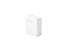
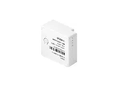
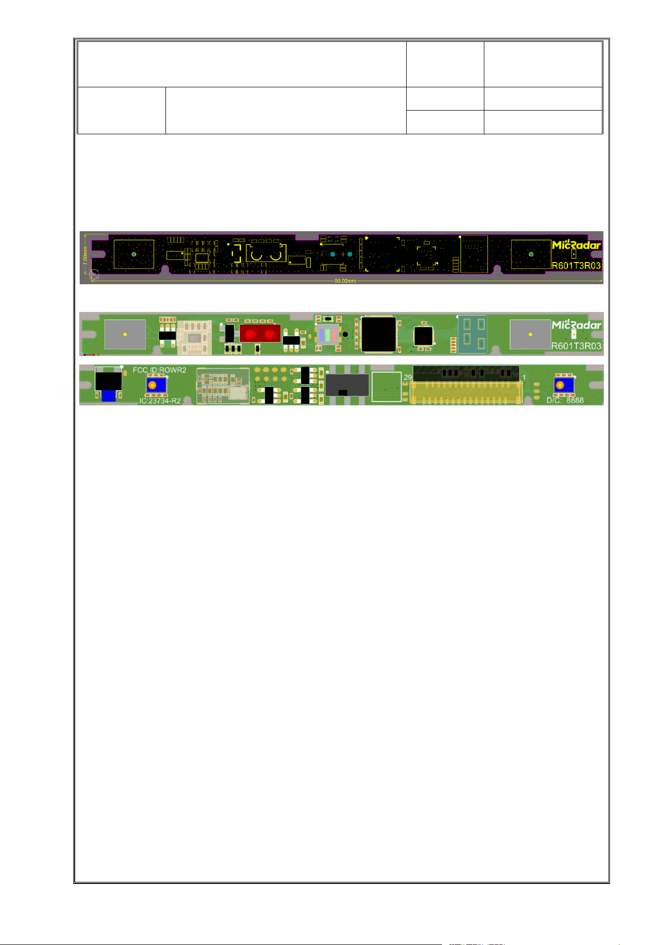
1.1. Appearance and Dimensions
(1) The dimensional tolerance above is ±0.2mm.
(2) The device appearance shall be smooth, clean, free of oil stains, scratches and cracks;
the device pins shall be free of deformation and the surface shall be free of oxidation; the
front of the device shall be marked with clear and durable logos or information.
(3) Model Marking: Composed of letters and numbers, the model marking shallbeeasyto
identify and distinguish; in case of any change, the manufacturer is obliged to provide a
reasonable explanation and notify officially in a timely manner.
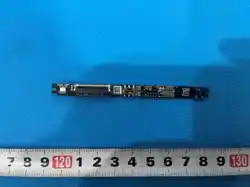
(4) Structural dimensions shall be described by structural drawings with clear external
dimensions. For the transition content of lengthwidthheight and overall dimensions (or other
obvious differences), the typical values and tolerances (or maximum and minimum values)
Remarks:
深圳市中龙通电子科技有限公司
CHINA D
RAGON TECHNOLOGY LIMITED
Material
Category
Material
Model
R601T3R
03
Version
1.0
Page
4 /17
shall be marked. Enlarged drawings shall be provided for key parts that cannot be reflected in
the drawings.
1.2. Key Structure, Material and
Process
1.2.1.Board Material and PCB
• Board Material: FR-4
•
Surface Finishing: Immersion Gold
•
Lamination: 4-layer through hole + blind hole
•
Comparative Tracking Index: 250V
PCB design and manufacturing process shall avoid CAF (Conductive Anodic Filament) failure.
For example, "PCB must use CAF-resistant board material, and the via pitch shall be ≥0.4mm".
Note: CAF (Conductive Anodic Filament) refers to the migration of conductive cations, which is
specifically manifested as the reduction of PCB insulation performance caused by copper ion
migration between conductors, leading to circuit short-circuit failure in severe cases.
1.2.2.Connector Specification
The connector is intended to be F05078-30P-T SMD vertical t
ype.
深圳市中龙通电子科技有限公司
CHINA DRAGON
TECHNOLOGY LIMITED
Material
Category
Material
Model
R601T3R03
Version
1.0
Page
5
/17
2.
Material List
Serial
No.
Material
Name
Specification Unit Consu
mption
Supplier
1 Capacitor 0201, 10nf, ±20%, 16V pc 1.00 EYANG/VIIYONG/FENGHUA/Samsung/CCTC
2 Capacitor 0201, 470nf, ±20%, 10V pc 1.00 EYANG/VIIYONG/FENGHUA/Samsung/CCTC
3 Capacitor 0201, 100nf, ±20%, 16V pc 14.00 EYANG/VIIYONG/FENGHUA/Samsung/CCTC
4 Capacitor 0201, 1uf, ±20%, ≥6.3V pc 14.00 EYANG/VIIYONG/FENGHUA/Samsung/CCTC
5 Capacitor 0402, 10uf, ±20%, ≥6.3V pc 9.00 EYANG/VIIYONG/FENGHUA/Samsung/CCTC
6 Capacitor 0201, 1nf, ±20%, 16V pc 1.00 EYANG/VIIYONG/FENGHUA/Samsung/CCTC
7 Capacitor 0201, 100pf, ±20%, 10V pc 1.00 EYANG/VIIYONG/FENGHUA/Samsung/CCTC
8 Capacitor 0201, 4.7uf, ±20%, ≥6.3V pc 5.00 EYANG/VIIYONG/FENGHUA/Samsung/CCTC
深圳市中龙通电子科技有限公司
CHINA DRAGON TECHNOLOGY LIMITED
Material
Category
Material
Model
R601T3R03
Version
1.0
Page
6 /17
9 Resistor 0402, 0 ohm, ±5%, 1/16W pc 1.00 FENGHUA/FOSAN/uni-ohm
10 Resistor 0201, 10K ohm, ±5%,
1/16W
pc 6.00 FENGHUA/FOSAN/uni-ohm
11 Resistor 0201, 4.7K ohm, ±5%,
1/16W
pc 1.00 FENGHUA/FOSAN/uni-ohm
12 Resistor 0201, 150 ohm, ±5%,
1/16W
pc 1.00 FENGHUA/FOSAN/uni-ohm
13 Resistor 0201, 1K ohm, ±5%, 1/16W pc 4.00 FENGHUA/FOSAN/uni-ohm
14 Resistor 0201, 0 ohm, ±5%, 1/16W pc 4.00 FENGHUA/FOSAN/uni-ohm
15 Resistor 0201, 100 ohm, ±5%,
1/16W
pc 3.00 FENGHUA/FOSAN/uni-ohm
16 Resistor 0201, 2.2K ohm, ±5%,
1/16W
pc 2.00 FENGHUA/FOSAN/uni-ohm
17 Resistor 0201, 100K ohm, ±5%,
1/16W
pc 1.00 FENGHUA/FOSAN/uni-ohm
18 Resistor 0201, 499 ohm, ±5%,
1/16W
pc 1.00 FENGHUA/FOSAN/uni-ohm
19 Resistor 0201, 51 ohm, ±5%, 1/16W pc 2.00 FENGHUA/FOSAN/uni-ohm
20 Bead 0402, 600 ohm, 100Mhz,
±25%, 200mA, TDK,
MMZ1005B601CT000
pc 5.00 TDK
21 Bead 0402, 120 ohm, 100Mhz,
±25%, 500mA, TDK,
MMZ1005S121CT000
pc 1.00 TDK
22 NMOS 2N7002K \ SOT23 pc 1.00 CJ
23 LED Model: 16-213/T3D-
KP1Q2QY/3T<br/>Supplier:
EVERLIGHT<br/>Character
istic: White
pc 1.00 EVERLIGHT
24 Tact Switch KAN4567-0501C0101-A pc 1.00 KangJia
25 Toggle
Switch
MSS22C07-TG2-MB1 pc 1.00 KangJia
26 Infrared SDR6438-TT pc 1.00 HEG (Haige Technology)
深圳市中龙通电子科技有限公司
CHINA DRAGON TECHNOLOGY LIMITED
Material
Category
Material
Model
R601T3R03
Version
1.0
Page
7 /17
27 MIC MIC-MSM371DDB024 pc 2.00 MX Microsystems
28 Ambient
Light
Sensor
STK2736 pc 1.00 sensortek
29 RGB Light RGB-LT3735RGBCT-IC4-
S21
pc 1.00 PARA Light
30 AND Gate SN74AHC1G08DBVR pc 1.00 TI
31 FPC F05078-30P-T SMD vertical
type
pc 1.00 ChangTong
32 TVS Diode PESDNC2FD5VB-ES pc 2.00 Corelead
33 TVS Diode PESDNC2FD3V3B pc 17.00 Corelead
34 Power LDO SOT23-5, RS3236-3.3YF5 pc 3.00 SongYuan
35 Power LDO SOT23-5, RS3236-1.8YF5 pc 1.00 SongYuan
36 Crystal
Oscillator
2016, 80Mhz, Active, 1.8V,
±3ppm, YXC, YSO690PR
pc 1.00 SongYuan
37 Integrated
Circuit
QFN3*3-20L, RUNSIC,
RS0208
pc 1.00 SongYuan
38 Integrated
Circuit
QFN48, Artery,
AT32F403ACGU7 (Small)
pc 1.00 SongYuan
39 Integrated
Circuit
BGA, IFX, BGT60TR13C pc 1.00 SongYuan
40 Printed
Circuit
Board
Black Solder Mask with
White Silkscreen
pc 1.00 SongYuan
41 Seal MIC Sealing Adhesive
Sticker
pc 2.00 Liuchun Intelligence
3. Technical Specifications, Performance Parameters and
Test Methods
深圳市中龙通电子科技有限公司
CHINA DRAGON T
ECHNOLOGY LIMITED
Material
Category
Material
Model
R601T3R03
Version
1.0
Page
8/17
3.1.
Basic Characteristics
A. Radar Electrical Performance Parameters
1) Operating Frequency Band: 58.0-61.0GHz
2) Radar Bandwidth: 2878.54MHz
3) Transmit Power: ≤11.97dBm
4) Detection Range: ≤±50°
5) Radar Transmit Channel: 1
6) Radar Receive Channel: 3
B. Functional Requirements
a) Moving human detection
b) Stationary human detection
C. Performance Parameter Requirements
Serial No.
Functional Content Functional Index
1 Detection Range Moving: ≥5m, ≤±50°<br/>Stationary:
≥5m, ≤±50°
2 Supported Detected Persons 1 person (nearest person detection)
3 Detection Time for Personnel
Entering the Area
Moving target ≤500ms; Stationary
person presence ≤60S
4 Detection Rate of Personnel
Entering the Area
Moving detection rate:
≥98%<br/>Stationary detection rate:
≥90%
5 False Detection Rate of
Unmanned Condition
≤0.5% (in open space without vibration,
moving targets such as curtain shaking,
green plant swaying, fan rotation, etc.)
6 Detection Angle Error (Single
Person)
≤±10° (the angle error will be larger
when the distance is less than 2m and
the angle is larger than 30°)
深圳市中龙通电子科技有限公司
CHINA DRAGON TECHNOLOGY LIMITED
Material
Category
Material
Model
R601T3R03
Version
1.0
Page
9
/17
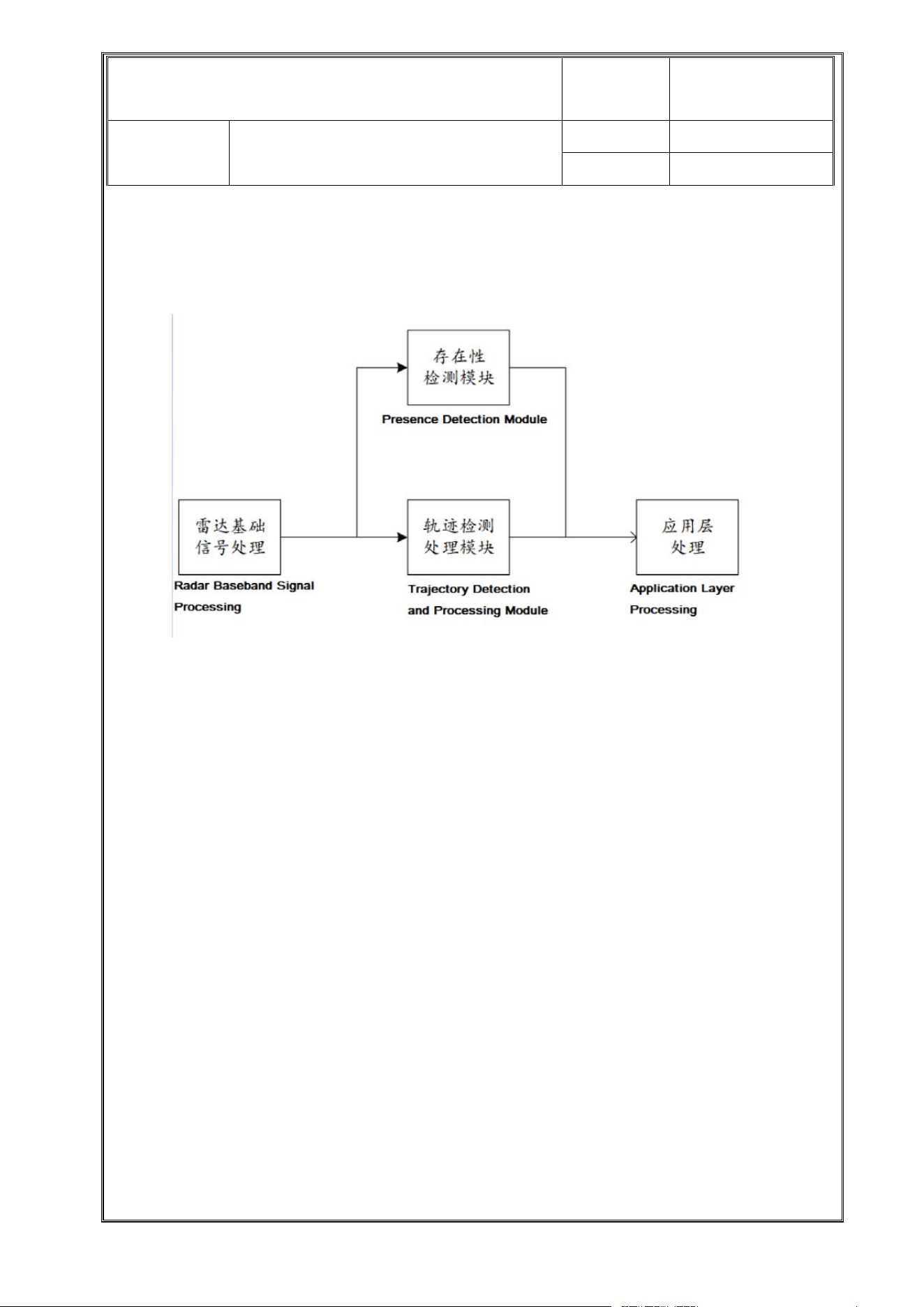
3.2. Product Functions and Application Logic
3.2.1.
Radar Product Functional Block Diagram
This radar can separately implement functions such as presence detection of people in the
current scene range, real-time trajectory detection of moving targets, etc. These detection
parameters are then centrally processed by the application layer to realize radar scene
detection and evaluation, as well as radar application processing.
The radar product sets three transmission mechanisms for the output of various parameter
indicators:
A. Active Reporting Mechanism
B. Query Feedback Mechanism
C. Issuance and Setting Mechanism
3.2.2.Application Layer Scheduling Mechanism
The radar has the following processing mechanisms at the application layer:
(1) When the radar detects no one in the current scene, it only performs human
presence/absence detection. In the unmanned environment, the radar will enter the low-
power mode (reduced refresh rate) and wake up to the normal mode after detecting
movement.
(2) When the radar detects human movement in the area, it performs trajectory tracking and
position monitoring.
(3) The basic data detected by the above radar can be called by users to facilitate the
secondary development of the user's application layer logic.

深圳市中龙通电子科技有限公司
CHINA DRAGON TECHNOLOGY LIMITED
Material
Category
Material
Model
R601T3R03
Version
1.0
Page
1
0/17
3.3. Interface Definition and Timing
3.3.1. Hardware Interface Definition
The external interface of the radar module is intended to adopt F05078-30P-TSMD vertical type.
Hardware Interface of Radar Module:
28/29/30 VCC_5V_RADAR: Power input of radar module, 5V power supplied independently by the main
board
23 RADAR RX: RX of radar module, connected to TX of main board
22 RADAR TX: TX of radar module, connected to RX of main board
21 NRST: Radar reset pin, low level reset

深圳市中龙通电子科技有限公司
CHINA DRAGON TECHNOLOGY LIMITED
Material
Category
Material
Model
R601T3R03
Version
1.0
Page
1
1 /17
20 HX-WAKEUP: IO of radar module, can be used as wake-up pin
19 LED_WHITE 2: Dual-color LED light control pin 2
18 KEYPAD-KEY1: Tact switch, single IO, low level trigger, pulled down when pressed
17 I2C_SDA_Sensor: I2C SDA of ambient light sensor
16 I2C_SCL_Sensor: I2C CLK of ambient light sensor
13 HVCC_MIC_5V: Independent 5V power supply for MIC, compatible with RGB light power supply
12 VCC33V_Sensor: 3.3V power supply pin for ambient light sensor, 3.3V supplied independently by the
main board
11 LED_WHITE 1: White LED control pin / Dual-color LED control pin 1
10 VCC33V_STB: 3.3V power supply continuously provided by the main board without power failure, for R
and white LED power supply
09 IR: Infrared IR signal output
07 PDM_DO: DATA of MIC chip output through AND gate
05 PDM_BCK: I2C CLK of MIC chip
03 RGB_LED_FF: RGB light effect control pin
01 Mute_MIC_Det: AND gate B pin of MIC circuit controlled by software
3.3.2. Software Interface Definition
See the Software Interface Protocol Document.
深圳市中龙通电子科技有限公司
CHINA DRAGON TECHNOLOGY LIMITED
Material
Category
Material
Model
R601T3R03
Version
1.0
Page
1
2 /17
4. Reliability Test Requirements
Serial
No.
Test Step
Test Condition Judgment Standard
1 Low
Temperature
Storage Test
(Millimeter
Wave)
The module is unpowered, placed
in a test chamber at -40℃ (or the
minimum storage temperature
required by the module) for 24h,
then taken out and recovered at
room temperature for 1h before
evaluation. Cross-hatch test shall
be conducted on the whole
machine shell with surface
finishing.
a) Performance Test: No abnormality
in voltage and current after the
test;<br/>b) Functional Check: No
abnormality in millimeter wave
function after power-on
inspection;<br/>c) Appearance
Check: No poor soldering, no missing
metal coating, no surface coating
damage, no device damage, no
connector abnormality, no shrapnel
damage, no warping/delamination on
PCB surface, no wrinkling of labels,
clear label and marking content, no
warping/deformation of shield, no
obvious tactile scratches, no visible
oxidation and rust spots.
2High
Temperature
Storage Test
(Millimeter
Wave)
The module is unpowered, placed
in a test chamber at 85℃ (or the
maximum storage temperature
required by the module) for 24h,
then taken out and recovered at
room temperature for 1h before
evaluation. Cross-hatch test shall
be conducted on the whole
machine shell with surface
finishing.<br/>Note: The test shall
be performed in accordance with
the product specification input first;
if there is no clear specification
input, it is recommended to refer to
-40℃/85℃.
Same as the judgment standard of
Low Temperature Storage Test.
3 Temperature
Shock Test
(Millimeter
Wave)
The module is unpowered, placed
in a low temperature chamber at -
40℃ for 15s, then quickly moved to
a high temperature chamber at
+85℃ within 15s and kept for 15s,
then quickly returned to the low
temperature chamber within 15s.
This is one cycle, a total of 10
cycles. After the test, the prototype
is taken out from the high
temperature (high/low temperature
chamber) and recovered at room
temperature (20~25℃) for 1h
Same as the judgment standard of
Low Temperature Storage Test.
深圳市中龙通电子科技有限公司
CHINA DRAGON TECHNOLOGY LIMITED
Material
Category
Material
Model
R601T3R03
Version
1.0
Page
1
3/17
before appearance, structure and
function inspection.<br/>Note: For
modules with clear specification
requirements, the test shall be
conducted with reference to the
upper and lower limit temperatures
of high and low temperature
storage tests in the module
specification (e.g., TV modules are
usually -40℃~85℃).
4Reliability
(Temperature
and Humidity
Cycling Test)
a) Conduct structural, appearance,
functional and performance
inspection on the prototype to be
tested at room temperature.<br/>b)
The module is powered with
nominal voltage, turned on and
placed in an environmental test
chamber with humidity of 25℃ in
standby mode, and the test is
carried out according to the
following curve:<br/>1) Rise from
[25℃,95%RH]to[65℃,95%RH]
within 2.5h and keep for 3h;<br/>2)
Drop to [25℃, 95% RH] within
2.5h;<br/>3) Rise to [65℃,95%
RH] within 2.5h and keep for
3h;<br/>4) Drop to [25℃,95%RH]
within 2.5h and keep for
1.5h;<br/>5) Drop to [-10℃]within
0.5h and keep for 3h;<br/>6) Rise
to [25℃, 95% RH] within 1.5h and
keep for 1.5h;<br/>c) Steps (1) to
(6) above are one cycle of 24h, a
total of 2 cycles;<br/>d) Conduct
appearance and function test
immediately after the test. If there is
an abnormality in appearance and
function, the prototype can be
placed at room temperature for
30min and rechecked to judge
whether the abnormal phenomenon
can disappear.
Same as the judgment standard of
Low Temperature Storage Test.
5 Low
Temperature
Operation
Test
(Millimeter
Wave)
The module is powered with
nominal and limit voltage
respectively, set to on state and
kept in standby, placed in a test
chamber at -25℃ (or the minimum
operating temperature required by
the module) for continuous
operation for 8h. After the test,
perform performance test and
function, structure, appearance
Same as the judgment standard of
Low Temperature Storage Test.
深圳市中龙通电子科技有限公司
CHINA DRAGON TECHNOLOGY LIMITED
Material
Category
Material
Model
R601T3R03
Version
1.0
Page
1
4 /17
inspection with a comprehensive
tester in this
environment.<br/>Note: The test
shall be performed in accordance
with the product specification input
first; if there is no clear specification
input, it is recommended to refer to
-25℃.
6High
Temperature
Operation
Test
(Millimeter
Wave)
The module is powered with
nominal and limit voltage
respectively, set to on state and
kept in standby, placed in a test
chamber at 80℃ (or the maximum
operating temperature required by
the module) for continuous
operation for 8h. After the test,
perform performance test and
function, structure, appearance
inspection with a comprehensive
tester in this
environment.<br/>Note: The test
shall be performed in accordance
with the product specification input
first; if there is no clear specification
input, it is recommended to refer to
80℃.
Same as the judgment standard of
Low Temperature Storage Test.
7 Temperature
Cycling Test
(Millimeter
Wave)
The module is powered with
nominal voltage, placed in a high
and low temperature test chamber
in on state, kept at -30℃ for 30min,
heated up to 85℃ at a rate of
10℃/min and kept for 30min, then
cooled down to -30℃ at a rate of
10℃/min. This is one cycle, a total
of 50 cycles. After the test, recover
at room temperature for 1h and
conduct function and performance
inspection.<br/>Note: For modules
with clear specification
requirements, the test shall be
conducted with reference to the
upper and lower limit temperatures
of high and low temperature
operation tests in the module
specification (e.g., TV modules are
usually -10℃~70℃).
Same as the judgment standard of
Low Temperature Storage Test.

深圳市中龙通电子科技有限公司
CHINA DRAGON TECHNOLOGY LIMITED
Material
Category
Material
Model
R601T3R03
Version
1.0
Page
1
5 /17
5. Safety Certification Information
Non-safety part, no safety certification applicable.
6. Environmental Requirements
Raw materials, packaging materials and other materials used for components must comply with
the chemical substance restriction requirements of Hisense Q/RSAG J15.002.
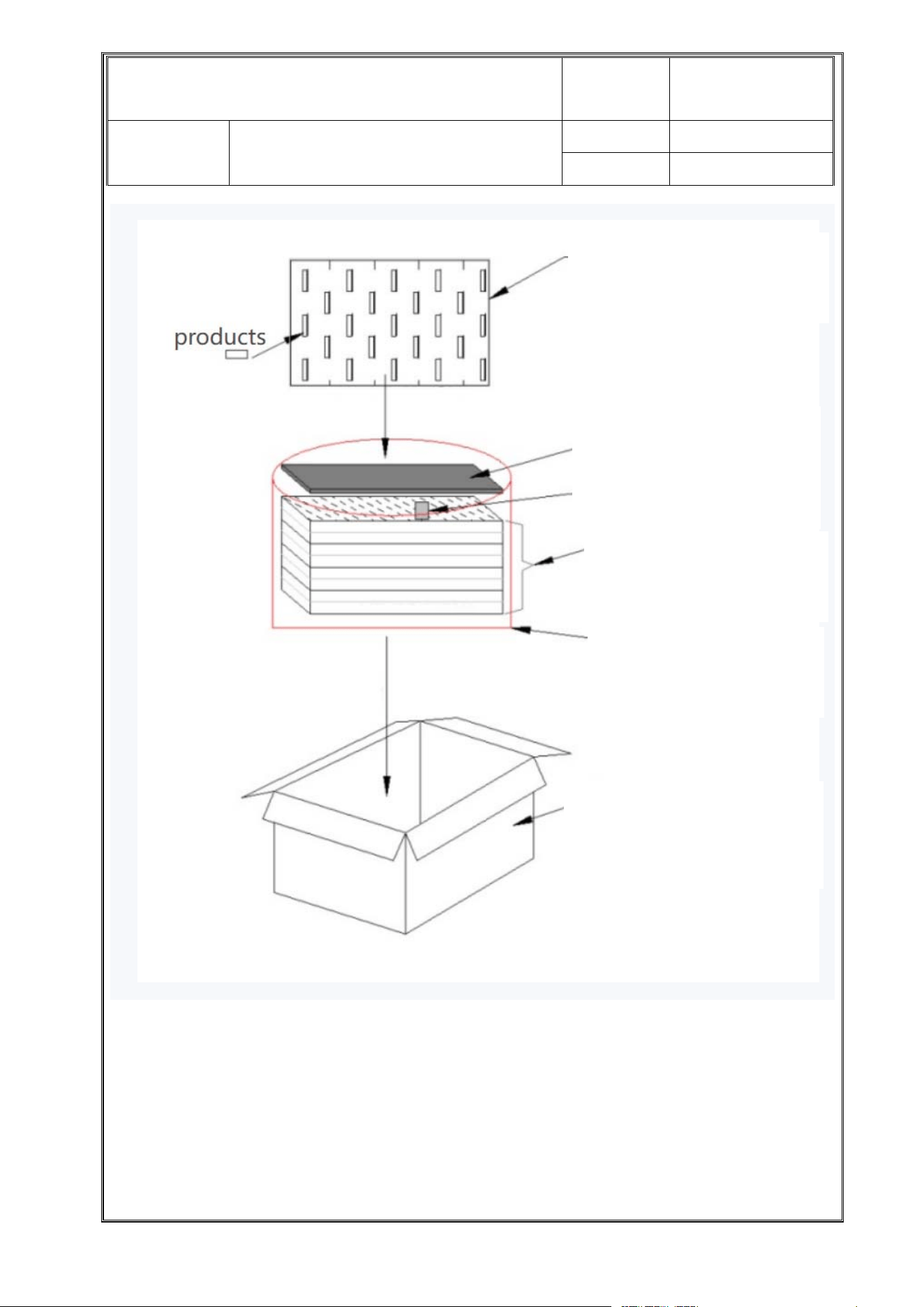
7. Packaging Specifications
深圳市中龙通电子科技有限公司
CHINA DRAGON TECHNOLOGY LIMITED
Material
Category
Material
Model
R601T3R03
Version
1.0
Page
1
6/17
8.
Transportation and Storage Environmental Requirements
EPE Foam: 35*25.5*2.0cm,
34 pcs of products loaded per
layer
Partition Board: 33*25.5cm
Desiccant and Temperature
Card
Total 7 layers of EPE Foam,
total 238 pcs of products
loaded
Red Anti-static Packaging
Bag (non-vacuum sealed)
loaded into the
outer carton
Outer Carton (K=A):
37*26.5*14.5cm,
total 238 pcs of products
loaded

深圳市中龙通电子科技有限公司
CHINA DRAGON TECHNOLOGY LIMITED
Material
Category
Material
Model
R601T3R03
Version
1.0
Page
1
7 /17
8.1.
Transportation Requirements
8.1.1 Good packaging shall be provided during transportation to ensure that the product will not
be damaged by environmental atmosphere or improper stress.
8.1.2 Severe impact or shock shall be avoided during transportation. The product shall be
protected from water and moisture during transportation.
8.1.3 The temperature and humidity of the transportation environment shall meet the storage
conditions.
8.1.4 When transporting electrostatic sensitive devices, they shall be placed in anti-static
packaging, and an ion fan shall be used to eliminate static electricity generated during
transportation if necessary.
8.2.
Storage Requirements
8.2.1 The product must be stored in a clean, ventilated warehouse free of corrosive gas.
8.2.2 Items with anti-static requirements shall be stored in an anti-static environment.
8.2.3 The storage life of the device is one year. The storage warehouse temperature is -
40~85℃, and the relative humidity is not more than 75%RH.
9 Normative References
GB 8702-2014 Electromagnetic Environment Control Limits
Radio Frequency Allocation Regulations of the People's Republic of China (2018.2.7)

Module
integration Description
Integration instructions for host product manufacturers according to 996369 D03 OEM Manual v01r01
10.1 List of applicable FCC rules
CFR 47 FCC PART 15 SUBPART C has been investigated. It is applicable to the modular.
10.2 Specific operational use conditions
This module is stand-alone modular. If the end product will involve the Multiple simult
aneously transmitting condition
or different operational conditions for ast
and-alone modular transmitter in a host, host manufacturer have to consult
with module manufacturer for the installation method in end system.
10.3 Limited module procedures
Not applicable
10.4 Trace antenna designs
Not applicable
10.5 RF exposure considera
tions
To maintain c
ompliance with FCC’s RF Exposure guidelines, this equipment should be installed and operated
with minimum distance of 20cm from
your body.
10.6 Antennas
This radio transmitter FCC ID: ROWR2 has
been approved by Federal Communications Commission to operate with
the antenna types
listed below, with the maximum permissible gain indicated. Antenna types not included in this list that
have a gain greater than the maximu
m gain i
ndicated for any type listed are strictly prohibited for use with this
device.
Antenna Type Maximum antenna gain
Microstrip patch 60G Radar module:5dBi
10.7 Label and c
ompliance information
The final end pro
duct must be labeled in a visible area with the fol
lowing" Contains FCC ID:ROWR2”
10.8 Information on test modes and ad
ditional testing requirements
Host manufacturer is strongly recommended to confirm compliance with FCC requirements for th
e transmitter when the
module is installed in the host.
10.9 Additional testing, Part 15 Subpart B disclaimer
Host manufacturer is respons
ible for compliance of the host system with module installed with all other applicable
requirements for the system such as Part 15 B
This device is intended only for OEM integrators under the following condition:
The transmitter module may not be co-located with any other transmitter or antenna. As long as the condition above is
met, further transmitter test will not be required. However, the OEM integrator is still responsible for testing their
end-product for any additional compliance requirements required with this
module installed.
Cet appareil est conçu uniquement pour les intégrateurs OEM dans les conditions suivantes:
Le module émetteur peut ne pas être coïmplanté avec un autre émetteur ou antenne. Tant que les 1
condition ci-dessus
sont remplies, des essais supplémentaires sur l'émetteur ne seront pas nécessaires. Toutefois, l'intégrateur OEM est
toujours responsable des essais sur son produit final pour toutes exigences de conformité supplémentaires requis pour ce
module installé.
Impor
tant Note:
I
n the event that these conditions cannot be met (for example certain laptop configurations or co-location with another
transmitter), the
n the Canada authorization is no longer considered valid and the ISED cannot be used on the final product.
In these circumstances, the OEM integrator will be responsible for reevaluating the end product (including th
e transmitter)
and obtaining a separate Canada authorization. Any company of the host device which in
stall this modular with
limit modular approval should perform the test of radiated emission and spurious e
mission according to RSS-210 and
RSS Gen requirement, only if the test result comply with RSS-210 and RSS-Gen requirement, then the host can be sold
legally.

No
te Importante:
Dans le cas où ces conditions ne peuvent être satisfaites (par exemple pour certaines configurations d'ordinateur portable
ou de certaines co-localisation avec un autre émetteur), l'autorisation du Canada n'est plus considéré comme valide et
l' ISED ne peut pas être utilisé sur le produit final. Dans ces circonstances, l'intégrateur OEM sera chargé de réévaluer le
produit final (y compris l'émetteur) et l'obtention d'une autorisation distincte au Canada. toute entreprise de l'hôte qui
installent ce dispositif modulaire avec limite approbation devrait effectuer l'essai des modules et des rayonnements
non essentiels des émissions rayonnées selon RSS-210 et le cnr - gen, seulement si le résultat d'essai conforme RSS-210
et le cnr -gen, puis l'hôte peut être vendu légalement.
En
d Product Labeling
The final end product must be labeled in a visible area with the following: Contains IC:23734-R2
Plaque signalétique du produit final
Le produit final doit être étiqueté dans un endroit visible avec l'inscription suivante: Contient des IC: 23734-R2.
Man
ual Information to the End User
The OEM integrator has to be aware not to provide information to the end user regarding how to install or remove this RF
module in the user’s manual of the end product which integrates this module.
The end user manual shall include all required regulatory information/warning as show in this manual.
Manuel d'information à l'utilisateur final
L'intégrateur OEM doit être conscient de ne pas fournir des informations à l'utilisateur final quant à la façon d'installer ou
de supprimer ce module RF dans le manuel de l'utilisateur du produit final qui intègre ce module.
Le manuel de l'utilisateur final doit inclure toutes les informations réglementaires requises et avertissements comme
indiqué dans ce manuel.
IS
ED Statement
This device contains licence-exempt transmitter(s)/receiver(s) that comply with Innovation, Science and Economic
Development Canada's licence-exempt RSS(s). Operation is subject to the following two conditions:
(1) This device may not cause interference.
(2) This device must accept any interference, including interference that may cause undesired operation of the device.
C
et appareil contient des émetteurs/récepteurs sans licence qui sont conformes aux RSS sans licence d'Innovation,
Sciences et Développement économique Canada. L'exploitation est soumise aux deux conditions suivantes :
(1) Cet appareil ne doit pas causer d'interférences.
(2) Cet appareil doit accepter toute interférence, y compris les interférences qui pourraient causer un fonctionnement
indésirable de l'appareil.
ISE
DC Radiation Exposure Statement:
This equipment complies with ISEDC RF radiation exposure limits set forth for an uncontrolled environment.
This transmitter must not be co-located or operating in conjunction with any other antenna or transmitter.
T
h
i
s equipment should be installed and operated with minimum distance 20cm between the radiator& your body.
Cet appareil est
conforme aux limitesd’exposition de rayonnement RF ISEDC établiespour un environnement non contrôlé.
Cetémetteur ne doit pas être co-implanté oufonctionner en onjunction avec toute autreantenne ou transmetteur.
Cet
équipement doit être installé et utilisé avec une distance minimale de 20cm entre le radiateur et votre corps.

FCC W
ARNING
Th
is device complies with part 15 of the FCC Rules. Operation is subject to the following two conditions: (1) This device
may not cause harmful interference, and (2) this device must accept any interference received, including interference that may
cause undesired operation.
Any changes or modifications not expressly approved by the party responsible for compliance could void the user's
authority to operate the equipment.
This equipment has been tested and found to comply with the limits for a Class B digital device,
pursuant to part 15 of the FCC Rules. These limits are designed to provide reasonable protection against harmful interference
in a residential installation. This equipment generates, uses and can radiate radio frequency energy and, if not installed and
used in accordance with the instructions, may cause harmful interference to radio communications. However, there is no
guarantee that interference will not occur in a particular installation. If this equipment does cause harmful interference to
radio or television reception, which can be determined by turning the equipment off and on, the user is encouraged to try to
correct the interference by one or more of the following
measures:
—Reorient or relocate the receiving antenna.
—Increase the separation between the equipment and receiver.
—Connect the equipment into an outlet on a circuit different from that to which the receiver is connected.
—Consult the dealer or an experienced radio/TV technician for help.
FC
C Radiation Exposure Statement
This equipment complies with FCC radiation exposure limits set forth for an uncontrolled environment .
Thi
s transmitter must not be co
-lo
cated or operating in conjunction with any other antenna or transmitter.
Thi
s equipment should be installed and operated with minimum distance 20cm between the radiator&
your body.
The product not to use on aircraft or satellites.