Service Handbook
PRINTED 0519
Surface-Mounted/ElectronicControls 52/80/120 Gallon Models
INSTALLATION CONSIDERATIONS - PRE SERVICE CHECKS
- WATER HEATER CONSTRUCTION - OPERATION & SERVICE
- TROUBLESHOOTING
SERVICING SHOULD ONLY BE PERFORMED BY A QUALIFIED SERVICE TECHNICIAN
100319205 100319205 (Rev. B)
COMMERCIAL ELECTRIC WATER HEATERS
Printed on 6/17/2020 12:05 PM CT

2
Servicing should only be performed by a Qualied Service Technician
INTRODUCTION ................................................................ 3
Qualications - Qualied Service Agent .........................3
Service Warning ......................................................... 3
Important Service Reminder ........................................... 3
Instruction Manual ..........................................................4
Tools Required ...............................................................4
INSTALLATION CONSIDERATIONS ................................. 5
Closed Water Systems ...................................................5
Thermal Expansion ........................................................5
Electrical Requirements .................................................6
Grounding ..................................................................6
Power Supply .............................................................6
PRE SERVICE CHECKS ................................................... 7
Wiring Connections ........................................................7
Service Precautions .......................................................7
WATER HEATER CONSTRUCTION .................................. 8
Surface Mount Control Models .......................................8
Electronic Control Models ..............................................8
Heating Element Congurations .....................................8
Heating Element Voltage and kW Conversion Kits ....8
OPERATION & SERVICE .................................................11
Principles of Electricity ..................................................11
Voltage ...................................................................... 11
Amperage .................................................................11
Ohms ........................................................................11
Wattage ..................................................................... 11
Ohm's Law ................................................................12
Single- and Three-Phase Power ...................................13
Checking Single Phase (1Ø) Power .........................14
Checking Three Phase (3Ø) Power ..........................15
Phase Conversions - Surface Mount Control Models 16
Phase Conversions - Electronic Control Models .......17
Fuses ............................................................................. 18
Ohmmeter Method ....................................................18
Volt Meter Method ..................................................... 18
Surface Mount Thermostats ..........................................19
Thermostat & ECO Test ............................................20
Heating Elements ..........................................................21
Heating Element Construction ..................................21
Heating Element Ratings ..........................................22
Heating Element Congurations ...............................22
Heating Element Amperage ......................................23
Replacing Heating Elements .....................................27
Element Sensors ...........................................................28
Element Sensor Construction ...................................28
Element Sensor Functions ........................................ 28
Element Sensor Operation ........................................29
Contactors .....................................................................30
Contactor Construction - How They Work.................30
Contactor Congurations ..........................................31
Contactor Inspection .................................................32
Contactor Coil Voltage Test - At Contactor ................33
Contactor Coil Voltage Test - At CCB ........................34
Transformers .................................................................35
120 VAC Control Circuit Transformer Wiring ............35
120 VAC Control Circuit Transformer Test ................36
24 VAC Transformer Test ..........................................37
Immersion Temperature Probe ......................................38
ECO High Temperature Limit Switch ........................38
Temperature Sensor .................................................38
Temperature Sensor Resistance Test .......................39
Temperature Sensor DC Voltage Test ....................... 40
ECO Continuity Test .................................................. 40
ECO Voltage Test ...................................................... 41
ELECTRONIC CONTROLS ............................................. 42
Central Control Board (CCB) ......................................... 43
CCB Socket & Wiring Terminal Identication ............44
CCB Enable/Disable Circuit(s) Test ..........................46
Checking Power and Ground to the CCB .................47
Electronic Control System .............................................49
Control System Features ..........................................49
Control System Navigation .......................................49
The Desktop Screen .................................................50
Temperatures Menu ..................................................53
Temperature Settings ................................................ 54
Heater Status Menu ..................................................55
Economy Mode Setup Menu .....................................56
Alarm Output Setup Menu ........................................61
Display Settings Menu ..............................................62
Heater Information Menu ..........................................63
Current Fault / Alert Menu ......................................... 64
Restore Factory Defaults Menu ................................65
TROUBLESHOOTING ..................................................... 66
Common Service Problems ........................................... 66
No Hot Water ............................................................66
Not Enough Hot Water ..............................................66
Water Heater Trips Breaker ......................................67
Contactor Chatter ......................................................67
Surface-Mount Control Models ...................................... 67
Electronic control Models ..............................................67
Fault Conditions ........................................................67
Alert Conditions .........................................................67
Resetting Control System .........................................67
Fault And Alert Messages .............................................. 69
TABLE OF CONTENTS
Printed on 6/17/2020 12:05 PM CT

3
Servicing should only be performed by a Qualied Service Technician
INTRODUCTION
This service manual is designed to be an aid in servicing and troubleshooting the commercial electric water
heater models listed on the cover. The instructions, illustrations, and procedures contained in this manual are
used to verify proper operation and to diagnose and repair common service problems.
This service handbook does not replace or supersede the instruction manual that came with the water heater.
Always refer to the instruction manual that came with the water heater for complete installation instructions. If
the instruction manual is not available, copies can be obtained from the manufacturer's web site or by calling
the technical support phone number shown on the back cover of this manual.
Review the Common Service Problems (page 66) prior to performing any service procedures.
QUALIFICATIONS - QUALIFIED SERVICE AGENT
Servicing the products referenced in this manual requires ability equivalent to that of a Qualied Agency (as
dened by ANSI below) in the eld involved. Installation skills such as plumbing, electrical supply are required
in addition to diagnostic and electrical testing skills when performing service. Call the toll free phone number
listed on the back cover of this manual for technical assistance.
ANSI Z223.1 2006 Sec. 3.3.83: “Qualied Agency” - “Any individual, rm, corporation or company that either in person
or through a representative is engaged in and is responsible for (a) the installation, testing or replacement
of gas piping or (b) the connection, installation, testing, repair or servicing of appliances and equipment; that
is experienced in such work; that is familiar with all precautions required; and that has complied with all the
requirements of the authority having jurisdiction.”
SERVICE WARNING
If you are not qualied (as dened by ANSI above) and licensed or certied as required by the authority having
jurisdiction to perform a given task do not attempt to perform any of the service, diagnostic or troubleshooting
procedures described in this manual. If you do not understand the instructions given in this manual or do not
feel condent in your abilities to perform a given task do not attempt to perform any procedures outlined in
this manual. Call the toll free phone number listed on the back cover of this manual for technical assistance.
IMPORTANT SERVICE REMINDER
When performing any troubleshooting step outlined in this manual, always consider the wiring and connectors
between components. Perform a close visual inspection of all wiring and connectors to and from a given
component before replacement. Ensure wires were stripped before being crimped in a wire connector. Ensure
wires are crimped tightly in their connectors. Ensure connection pins in sockets and plugs are not damaged
or worn. Also ensure plugs and sockets are mating properly and providing good contact.
Failure to perform this critical step or failing to perform this step thoroughly often results in needless down
time, unnecessary parts replacement, and customer dissatisfaction.
Printed on 6/17/2020 12:05 PM CT

4
Servicing should only be performed by a Qualied Service Technician
INSTRUCTION MANUAL
Have a copy of the instruction manual that came with the water heater on hand for the correct model water
heater you are working with before servicing.
Installation information given in this service manual IS NOT a complete installation instruction. Installation
information covered in this service manual has a limited focus as it applies to servicing. This service manual
does not replace or supersede the instruction manual that came with the water heater. Always refer to the
instruction manual that came with the water heater for complete installation instructions.
If the instruction manual is not on hand, copies can be obtained from the manufacturer's web site or by calling
the technical support phone number shown on the water heater labeling and the back cover of this service
manual.
TOOLS REQUIRED
• The instruction manual that came with the water heater.
• All tools common to installation and service of commercial water heaters, such as hand tools, torch,
pipe wrenches, etc.
• Electrical switch lock out device - used to secure disconnect switches/breaker panels while servicing.
• Insulated fuse puller(s).
• Adhesive numbered/colored wire markers - 3M Scotch Code SDR0-9 Numbered Wire Markers; 3M
Scotch Code STD-C Colored Wire Markers or equivalent.
• Volt-Ohm Multi Meter - recommend Fieldpiece HS36, Fluke 187, UEI model DL289 or equivalent
capable of measuring:
• AC Voltage up to 600 VAC
• DC Voltage up to 24 VDC
• Ohms up to 2,000,000 ohms
• AC amp meter - recommend UEI model DL289 or equivalent capable of measuring:
• AC amperage up to 400 amps
Printed on 6/17/2020 12:05 PM CT

5
Servicing should only be performed by a Qualied Service Technician
INSTALLATION CONSIDERATIONS
Installation information given in this service manual IS NOT a complete installation instruction. Installation
information covered in this service manual has a limited focus as it applies to servicing. This service manual
does not replace or supersede the instruction manual that came with the water heater. Always refer to the
instruction manual that came with the water heater for complete installation instructions.
If the instruction manual that came with the water heater is not on hand, copies can be obtained from the
manufacturer's web site or by calling the technical support phone number shown on the water heater labeling
and the back cover of this service manual.
CLOSED WATER SYSTEMS
Water supply systems may, because of code requirements or such conditions as high line pressure among
others, have installed devices such as pressure reducing valves, check valves, and back-ow preventers.
Devices such as these cause the water system to be a closed system.
Virtually all commercial and most residential water supply systems are closed systems today. Closed water
systems will experience thermal expansion which, if not controlled with a properly installed and sized thermal
expansion tank, can cause premature failure (leakage) of the water heater. Water heater failure (leakage) on
closed systems where there is not a thermal expansion tank installed is not covered under the limited warranty.
THERMAL EXPANSION
As water is heated, it expands (thermal expansion). In a closed system the volume of water will grow when
it is heated. As the volume of water grows there will be a corresponding increase in water pressure due to
thermal expansion. Thermal expansion can cause premature tank failure (leakage). This type of failure is not
covered under the limited warranty. Thermal expansion can also cause intermittent temperature-pressure relief
valve operation: water discharged from the valve due to excessive pressure build up. This condition is not
covered under the limited warranty. The temperature-pressure relief valve is not intended for the constant relief
of thermal expansion.
A properly sized thermal expansion tank should be installed on all closed systems to control the harmful
effects of thermal expansion.
Printed on 6/17/2020 12:05 PM CT

6
Servicing should only be performed by a Qualied Service Technician
ELECTRICAL REQUIREMENTS
GROUNDING
Review the electrical ground requirements given in the instruction manual that came with the water heater
and ensure that the water heater has been properly grounded.
The water heater must be grounded in accordance with the National Electric Code and/or local codes. These
codes must be followed in all cases.
The water heater must be connected to a grounded metal, permanent wiring system; or an equipment grounding
conductor must be run with the circuit conductors and connected to the equipment grounding terminal or lead
on the water heater.
Service Note: The water heaters covered in this manual are equipped with electronic controls that may
experience erratic operation if the water heater is not properly grounded.
POWER SUPPLY
Review the electrical requirements listed on the water heater’s rating label and in the instruction manual that
came with the water heater. Ensure the branch circuit supplying power to the water heater is within these
requirements and properly connected.
Ensure the power supply phase (single or three phase / 1Ø, 3Ø) and power supply voltage match the water
heater’s rating label. See Single- and Three-Phase Power (page 13). The electric water heater models covered
by this service manual are phase convertible. See Phase Conversions - Surface Mount Control Models (page 16)
and Phase Conversions - Electronic Control Models (page 17).
Printed on 6/17/2020 12:05 PM CT

7
Servicing should only be performed by a Qualied Service Technician
PRE SERVICE CHECKS
WIRING CONNECTIONS
With the power supply to the water heater turned off, ensure that the wiring connections are properly tightened
to all components including: high-voltage terminal blocks, fuse blocks, contactors, transformers, and heating
elements.
Loose connections at any connection point will cause increased amperage and excessive heat, which can
damage wiring and components. Whenever worn or damaged wiring and components must be replaced,
ensure all wiring connections are properly tightened before putting the water heater back in service.
SERVICE PRECAUTIONS
1. DO NOT energize the branch circuit supplying power to the water heater or test the water heater electrical
system before the water heater is completely lled with water. Read the start-up procedures in the instruction
manual that came with the water heater.
2. Be sure to turn off the power and use a lock-out device at the branch circuit power supply disconnect switch
or breaker when servicing the electrical system of the water heater. Never touch electrical components
with wet hands or when standing in water.
3. When replacing heating elements, ensure they are rated at the correct voltage and kW for the water
heater being serviced. See Heating Element Ratings (page 22), Heating Element Congurations (page 22)
and Replacing Heating Elements (page 27).
4. When replacing fuses, use an insulated fuse puller to remove and install fuses. Always use the correct
size for the circuit. See the instruction manual that came with the water heater for fuse size requirements.
See Fuses (page 18).
5. Using an AC volt meter, measure the branch circuit power supply voltage to the water heater. Ensure the
measured voltage of the branch circuit supplying power to the water heater matches the water heater’s
rating label. See Single- and Three-Phase Power (page 13).
6. Ensure the internal power phase conguration matches the power supply to the water heater. The water
heaters covered by this manual are phase convertible. See Phase Conversions - Surface Mount Control Models
(page 16) and Phase Conversions - Electronic Control Models (page 17).
7. The electronic control models covered by this manual are equipped with contactors and a multi-tap
control circuit transformer. This is a step-down transformer that outputs 120 VAC (secondary winding),
which is used to power the electronic control system and energize the contactor coils. The transformer
can accommodate different power supply voltages and has multiple input voltage connections or “taps.”
Ensure the input supply voltage (primary winding) wiring to the transformer is connected properly. See
Transformers (page 35).
Service Note: Contactor Chatter: Incorrect supply voltage wiring to the multiple tap 120 VAC control-
circuit transformer will cause low/high output voltage from the transformer. This can
cause contactors to open and close their contacts rapidly (contactor chatter) and result
in permanent damage to the contactors. Ensure that the primary winding of the multiple
tap 120 VAC control circuit transformer is wired to match the power supply voltage. See
Transformers (page 35).
Printed on 6/17/2020 12:05 PM CT

8
Servicing should only be performed by a Qualied Service Technician
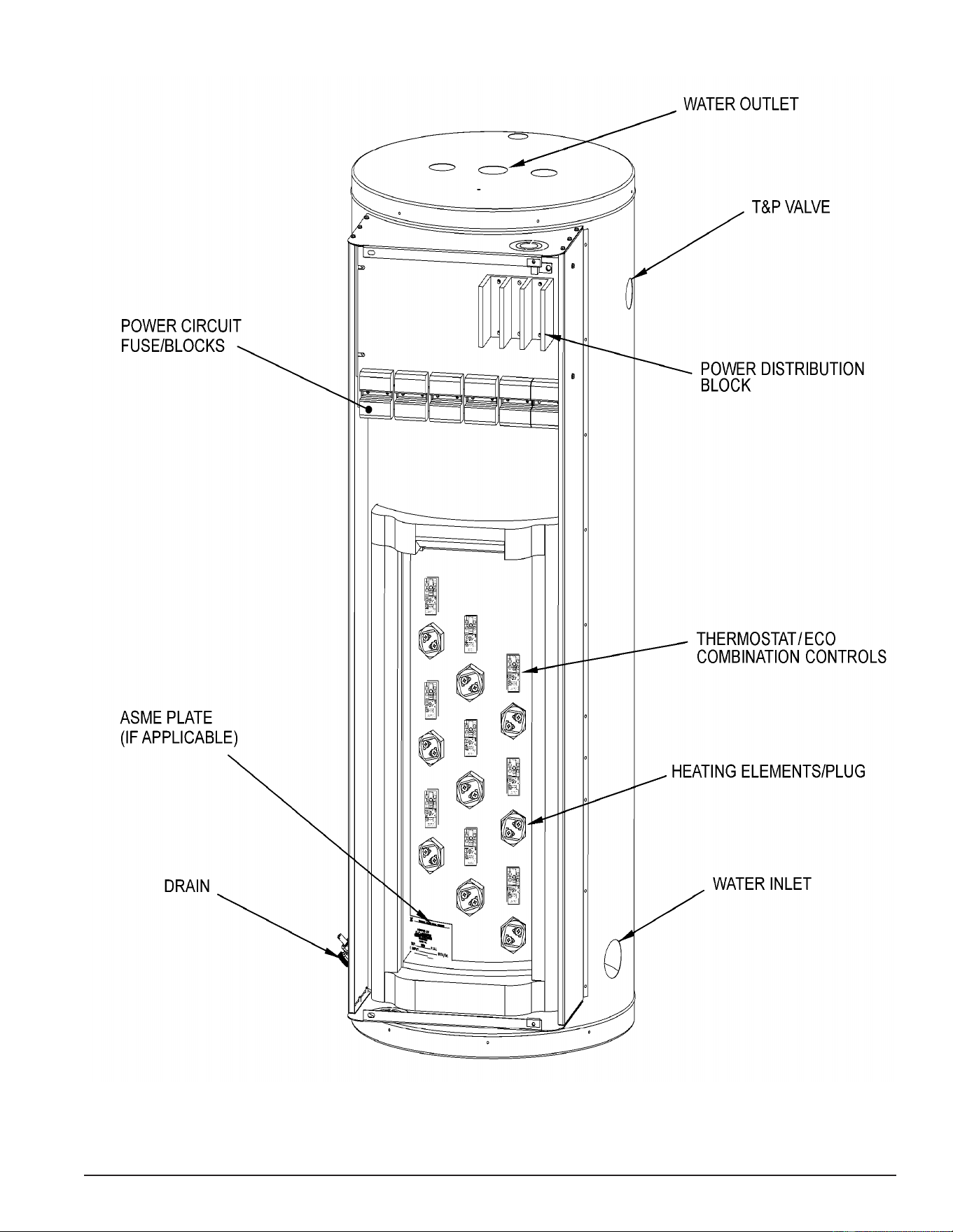
WATER HEATER CONSTRUCTION
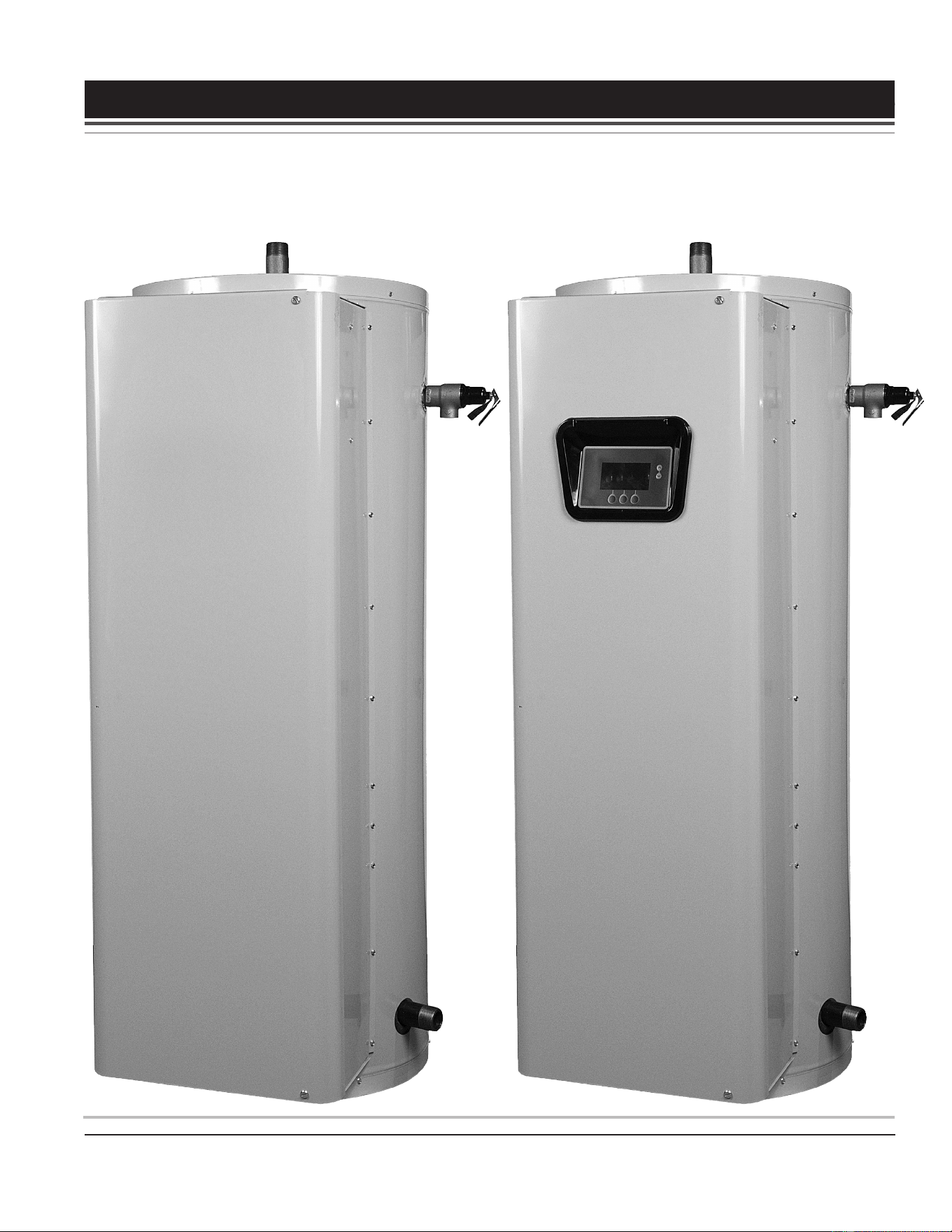
There are two types of commercial electric water heaters covered in this manual. See Figure 1 (page 9)
and Figure 2 (page 10).
SURFACE MOUNT CONTROL MODELS
The rst type of water heater covered in this manual is equipped with surface mount thermostat/ECO controls.
There will be separate thermostat/ECO (energy cut out) combination controls mounted to the surface of the
storage tank directly above the heating elements they control. For example, a water heater equipped with
9 heating elements will have 9 combination thermostat/ECO controls. These combination thermostat/ECO
controls sense temperature directly from the surface of the storage tank. Each combination control will have
a temperature setting adjustment screw. As the tank (water) temperature rises and falls, each individual
thermostat will de-energize and energize one heating element according to it’s temperature setting.
ELECTRONIC CONTROL MODELS
The second type of water heater covered in this manual is equipped with an electronic control system.
These are the electronic control models. The control system senses temperature electrically from an immersion
temperature probe. The probe is installed in a threaded opening in the storage tank (wet well) and senses water
temperature directly. As the stored water temperature rises and falls, the control system de-energizes and
energizes banks of three heating elements indirectly using electromagnetic contactors. The control system
energizes the electromagnetic contactor’s (120 VAC) coil, causing the switch contacts of the contactor to
close, which in turn supplies power to the heating elements.
HEATING ELEMENT CONFIGURATIONS
Both types of water heaters covered in this manual are factory equipped with either 3, 6 or 9 heating elements,
depending on how they were ordered from the factory. See Table 1 (page 22). Each group of 3 heating
elements (physically installed in diagonal rows of 3) is referred to as a “Bank” of heating elements. Bank 1 is
the lowest group of 3 heating elements, Bank 2 is the middle group of 3 heating elements, and Bank 3 is the
upper group of 3 heating elements. See Figure 1 (page 9) and Figure 2 (page 10).
HEATING ELEMENT VOLTAGE AND KW CONVERSION KITS
Voltage and heating element kW conversion kits are available for the water heaters covered in this manual.
Voltage and kW conversions are not covered in this manual. Voltage and kW conversion kits with instructions
are available from local distributors and can be ordered from the manufacturer’s parts department by calling
the toll free number listed on the back cover of this manual. Have the complete model and serial number
along with the listed voltage and input kW from the rating label of the water heater on hand before calling.
Service Note: There are eld conversion kits to increase/decrease kW input and change voltage. However,
conversion kits do not allow adding heating elements to a water heater. Water heaters must
remain as they were congured with 3, 6 or 9 heating elements from the factory. HEATING
ELEMENTS CANNOT BE ADDED TO A WATER HEATER.
Printed on 6/17/2020 12:05 PM CT
9
Servicing should only be performed by a Qualied Service Technician
Figure 1. Surface-Mounted Control Models
Printed on 6/17/2020 12:05 PM CT

10
Servicing should only be performed by a Qualied Service Technician
Figure 2. Electronic Control Models
Printed on 6/17/2020 12:05 PM CT

11
Servicing should only be performed by a Qualied Service Technician
OPERATION & SERVICE
This section of the manual will cover the principles of electricity, single- and three-phase power, fuses, heating
element construction & operation, heating element sensors, contactors, common service procedures, and
more. Information and service procedures presented in this section will be referenced in the troubleshooting
sections at the end of this manual.
PRINCIPLES OF ELECTRICITY
VOLTAGE
The unit of measurement used to quantify electrical pressure or the force that causes electrical energy to ow
is the volt or voltage. Volt meters are used to determine if there is an adequate supply of electricity or voltage
to a heating element.
AMPERAGE
The unit of measurement used to quantify the rate at which electrical current is owing is the ampere or amp.
Amp meters are used to determine if a heating element is working - if there is adequate current owing through
the heating element.
OHMS
The unit of measurement used to quantify the opposition or “resistance” to the ow of electricity is the ohm.
As resistance (ohms) in an electrical circuit increases current (amperage) will decrease and as resistance
decreases current will increase. Ohmmeters are used for measuring the resistance of heating elements, for
open circuit continuity tests on heating elements and for shorted to ground continuity tests on heating elements.
Service Note: Volt, ohm and amp meter test instruments are necessary to perform the service and
diagnostic procedures outlined in this manual. See Tools Required (page 4).
WATTAGE
The unit of measurement used to quantify the rate or amount of electrical energy being used is the watt. One
thousand watts is referred to as one kilowatt. Heating elements are rated in kilowatts expressed as kW. The
higher the kilowatt rating of a heating element the more power it will use and the more heat it will generate.
One kilowatt generates 3412 Btu of heat.
Printed on 6/17/2020 12:05 PM CT

12
Servicing should only be performed by a Qualied Service Technician
OHM'S LAW
A law that explains the relationship between voltage, current and resistance. The law states that the electric
current owing through a conductor is equal to the voltage divided by the resistance. The following equations
further explain Ohms Law.
V = volts (electrical pressure)
A = amps (electrical ow/current)
O = ohms (resistance to electrical ow/current)
W = watts (rate or amount of electricity used)
Ohm's Law applied to single phase power - each loop of a six wire element:
V ÷ A = O W ÷ V = A V ÷ O = A V x A = W A x O = V W ÷ A = V
Service Note: Heating elements used on the water heaters covered by this manual are “two wire” single
phase elements. Though the power supply to the water heater may be three phase,
calculations to determine amperage and resistance for individual heating elements is based
on Ohm's Law applied to single phase power. The kW rating of individual heating elements
is marked on the end of each element. See Figure 17 (page 22). Approximate current
(amps) and resistance (ohms) for individual heating elements are provided in tables in
Heating Element Amperage (page 23).
See the water heater’s rating label for the listed voltage/phase power supply requirements, total input kW,
and total/full load amp draw of the water heater being serviced.
Calculating Amps/Ohms/Volts/Watts
Using a 240 volt electric water heater equipped with a 4500 watt heating element as an example, Ohm's Law
can be used to determine:
1. What the resistance of each heating element should be:
• 240 volts ÷ 18.75 amps = 12.8 ohms
2. What the correct amp reading should be:
• 4500 watts ÷ 240 volts = 18.75 amps
• 240 volts ÷ 12.8 ohms = 18.75 amps
3. How many watts are being used (how much heat is being generated):
• 240 volts x 18.75 amps = 4500 watts (4.5 KW)
4. What the voltage is:
• 18.75 amps x 12.8 ohms = 240 volts
• 4500 watts ÷ 18.75 amps = 240 volts
Printed on 6/17/2020 12:05 PM CT
13
Servicing should only be performed by a Qualied Service Technician
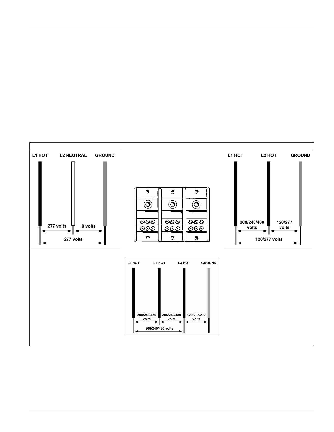
SINGLE- AND THREE-PHASE POWER
The water heaters covered in this manual can be eld converted for a single- or three-phase power supply.
See Phase Conversions - Surface Mount Control Models (page 16) and Phase Conversions - Electronic Control Models
(page 17). These water heaters can be factory ordered for standard North American power supplies;
277/208/240/480 volt models. 277-volt models are single phase only. Voltage conversion kits with instructions
are available from the manufacturer. Voltage conversions are not covered in this manual. Verifying that the
power supply is adequate is a typical rst step during most service diagnostic procedures. The illustrations and
instructions that follow outline how this is done using a standard AC volt meter. See Tools Required (page 4).
Service Warning: Never touch any wiring inside the water heater until the main power supply to the water
heater has been secured. Secure power to the water heater by turning off the power
supply breaker and/or disconnect switch AND verify with a volt meter that all wiring has
no voltage present before touching any wiring inside the water heater’s control panel.
Service Warning: Zero or low voltage readings between internal wiring and/or Power Distribution Block
terminals and ground can be due to an inadequate earth ground. TREAT ALL WIRES AS
BEING HOT until it has been determined there is no voltage present.
277 Volt 1Ø Power
Power Distribution Block
See Figure 1 (page 9) and Figure 2 (page 10). 208/240/480 Volt 1Ø Power
208/240/480 Volt 3Ø Power
Figure 3. Wire Identication for Verication of Power Supply
Printed on 6/17/2020 12:05 PM CT
14
Servicing should only be performed by a Qualied Service Technician
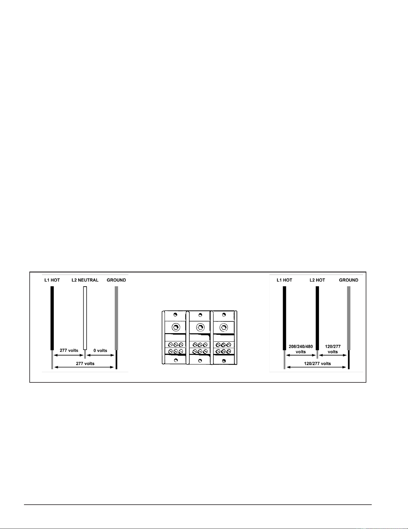
CHECKING SINGLE PHASE (1Ø) POWER
A single phase power supply consists of two wires connected to the L1 and L2 terminals of the Power Distribution
Block, the L3 terminal is not used. On a single phase (1Ø) 277 volt power supply one of the two wires is a
“neutral” wire and does have voltage present. On a single phase (1Ø) 277 volt power supply the “hot” wire
should be connected to the L1 terminal and the “neutral” wire should be connected to the L2 terminal. On 208,
240 and 480 volt power supplies both wires connected to L1 and L2 are “hot” with voltage present.
Voltage Between Terminals: With the power supply to the water heater turned on set the volt meter to an
AC voltage range above the expected voltage (600 VAC or higher range initially) and carefully touch the two
test probes to the L1 and L2 terminals of the water heater’s Power Distribution Block. The voltage readings
should match the voltage listed on the water heater’s rating label by ± 5%.
Voltage to Ground: With the power supply to the water heater turned on check between the L1 terminal and
the ground wire connection inside the water heater’s control panel. Check between L2 and ground in the same
way. On a 277 volt power supply only one of the two terminals should read 277 volts, the neutral will read
approximately zero volts. On 208/240 volt power supplies each reading should be approximately 120 volts to
ground. On 480 volt power supplies each reading to ground should be approximately 277 volts.
Service Warning: Zero or low voltage readings between internal wiring and/or Power Distribution Block
terminals and ground can be due to an inadequate earth ground. TREAT ALL WIRES AS
BEING HOT until it has been determined there is no voltage present.
If the voltage readings taken between L1 and L2 are more than ± 5% of the listed voltage on the water heater’s
rating label or if the readings to ground were far less (at or near zero volts) than expected: check the fuses
and the breaker and/or disconnect switch supplying power to the water heater. Contact a Qualied/Licensed
electrician to restore power. If the voltage readings taken are a standard voltage (277/208/240/480) but do
not match the listed voltage on the water heater’s rating label, secure power to the water heater. DO NOT
place it back in service. Contact the distributor and/or manufacturer to determine if the water heater can be
eld converted and/or replaced to match the power supply at the location.
277 Volt 1Ø Power
L1
L2 L3
Power Distribution Block
See Figure 1 (page 9) and Figure 2 (page 10). 208/240/480 Volt 1Ø Power
Figure 4. Measuring Power Supply Voltage to the Water Heater (1Ø Power)
Printed on 6/17/2020 12:05 PM CT
15
Servicing should only be performed by a Qualied Service Technician
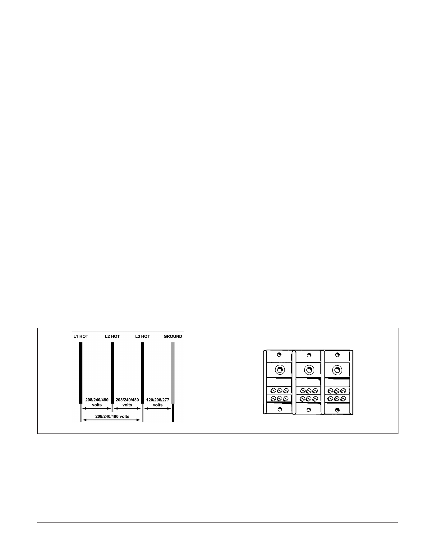
CHECKING THREE PHASE (3Ø) POWER
A three phase power supply consists of three wires connected to the L1, L2 and L3 terminals of the Power
Distribution Block. All three wires are “hot” with voltage present.
Voltage Between Terminals: Set the volt meter to an AC voltage range above the expected voltage (600
VAC or higher range initially). Checking three phase (3Ø) power requires that three voltage readings be taken
between all possible parings of the terminals on the Power Distribution Block. Carefully touch the two test
probes between:
1. L1 and L2 terminals of the water heater’s Power Distribution Block
2. L2 and L3 terminals of the water heater’s Power Distribution Block
3. L1 and L3 terminals of the water heater’s Power Distribution Block
All three voltage readings should match the voltage listed on the water heater’s rating label by ± 5%.
Voltage to Ground: Check between each of the three terminals (L1, L2 and L3) of the Power Distribution Block
and the ground wire connection inside the water heater’s control panel. On some 208 volt power supplies each
reading will be approximately 120 volts to ground. Some 208 volt models will have a “stinger leg” with one of
the three readings to ground measuring 208 volts - 208 volt stinger legs should be connected to L2. On 240
volt power supplies each reading should be approximately 120 volts to ground. On 480 power supplies each
reading to ground should be approximately 277 volts.
Service Warning: Zero or low voltage readings between internal wiring and/or Power Distribution Block
terminals and ground can be due to an inadequate earth ground. TREAT ALL WIRES
AS BEING HOT until it has been determined there is no voltage present.
If the voltage readings taken between L1, L2 and L3 are more than ± 5% of the listed voltage on the water
heater’s rating label or if the readings to ground were far less (at or near zero volts) than expected: check
the fuses and the breaker and/or disconnect switch supplying power to the water heater. Contact a Qualied/
Licensed electrician to restore power. If the voltage readings taken are a standard voltage (277/208/240/480)
but do not match the listed voltage on the water heater’s rating label secure power to the water heater. DO
NOT place it back in service. Contact the distributor and/or manufacturer to determine if the water heater can
be eld converted and/or replaced to match the power supply at the location.
208/240/480 Volt 3Ø Power
L1
L2 L3
Power Distribution Block
See Figure 1 (page 9) and Figure 2 (page 10).
Figure 5. Measuring Power Supply Voltage to the Water Heater (3Ø Power)
Printed on 6/17/2020 12:05 PM CT
16
Servicing should only be performed by a Qualied Service Technician
PHASE CONVERSIONS - SURFACE MOUNT CONTROL MODELS
Internal wiring connections between the Power Distribution Block and the heating elements are different on
Surface Mount Control (see Figure 1 (page 9)) and Electronic Control (see Figure 2 (page 10)) model
water heaters. Because of these differences there are two methods for eld converting these models to work
with single and three phase power supplies.
Service Note: 208 volt 54 kW models are 3 phase only and CAN NOT be converted to single phase. All
other models can be phase converted.
SECURE MAIN POWER SUPPLY TO THE WATER HEATER AT THE MAIN BREAKER OR DISCONNECT
SWITCH FIRST.
Service Warning: Never touch any wiring inside the water heater until the main power supply to the water
heater has been turned off. Verify with a volt meter that all wiring has no voltage present
before touching any wiring inside the water heater’s control panel.
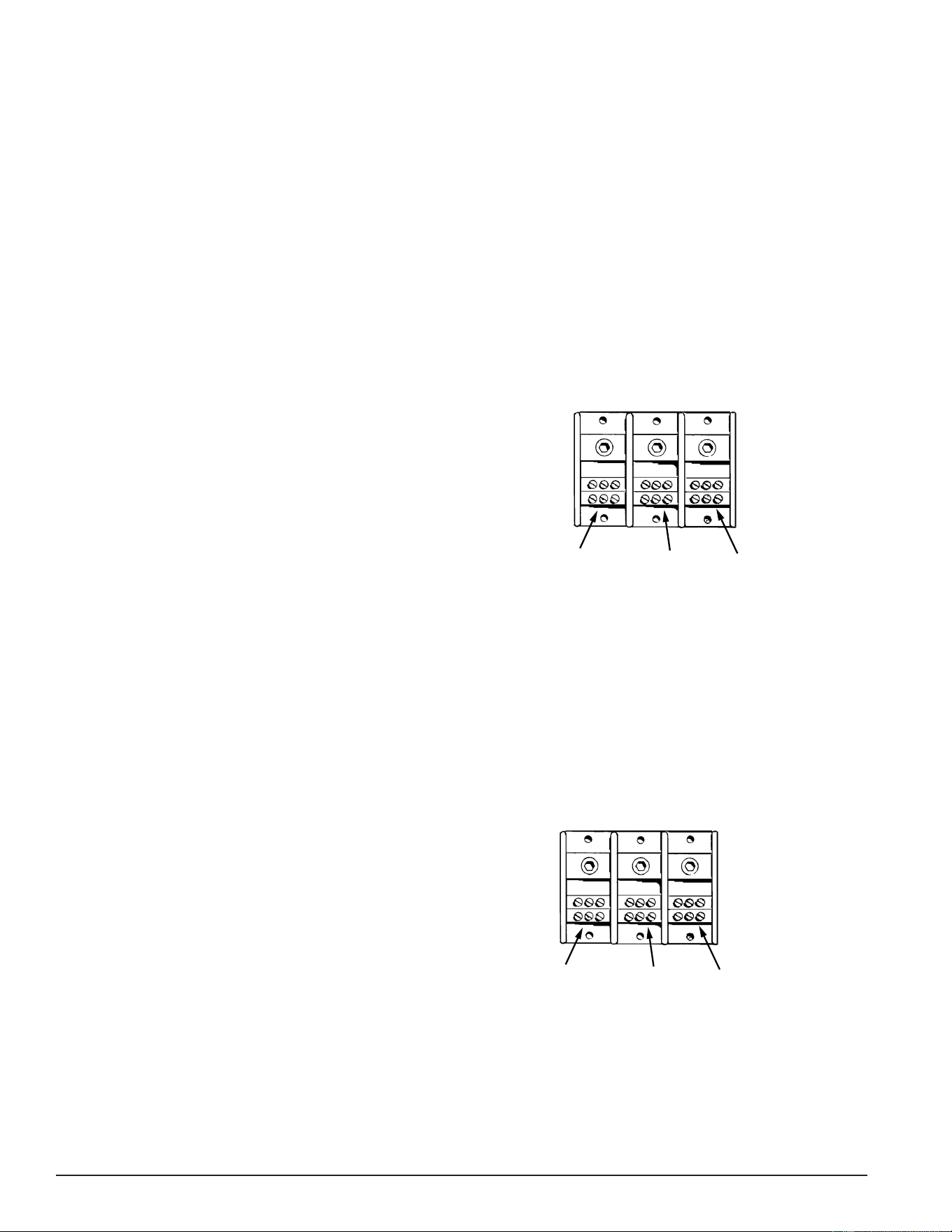
Surface-Mount Controls - Three Phase to Single Phase
1. Disconnect blue wires from terminal L-2.
2. Connect all blue wires to terminal L-1 (with black
wires).
3. Disconnect all red wires from terminal l-3.
4. Connect all red wires to terminal L-2 (with yellow
wires).
5. Incoming power will be connected to terminals L-1
and L-2.
L1
L2 L3
L1 All
Blue/Black
Wires
L2 All
Yellow/Red
Wires
No
Wires
Figure 6. Single-Phase Power Distribution Block Wiring.
See Figure 1 (page 9)
Service Note: 208 volt 54 kW models are three-phase only. These models CAN NOT be converted to single
phase. Keep in mind when converting other models from three phase power to single phase
power the current/amperage will increase signicantly. Ensure breakers, fuses and wiring
are properly sized to allow for the increased amperage before placing the water heater back
in service. Contact a Qualied/Licensed electrician to make necessary changes.
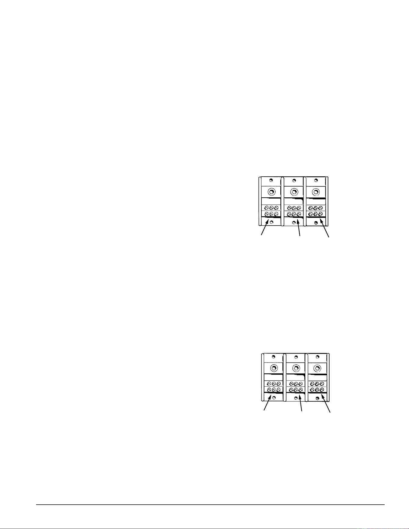
Surface-Mount Controls - Single Phase to Three Phase
Do the following to convert single-phase power to
three-phase power for water heaters with surface-
mount controls:
1. Disconnect blue wires from terminal L-1.
2. Disconnect red wires from terminal L-2.
3. Connect all blue wires to terminal L2 (with yellow
wires).
4. Connect red wires to terminal L3.
5. Incoming power will be connected to terminals L-1,
L-2, and L3.
L1
L2 L3
L1
All
Black
Wires
L2
All
Red
Wires
L3
All
Blue/Yellow
Wires
Figure 7. Three-Phase Power Distribution Block.
See Figure 1 (page 9).
Service Note: Keep in mind when converting from single phase power to three phase power, the current/
amperage will decrease signicantly. Ensure breakers and fuses are not oversized before
placing the water heater back in service. Contact a Qualied/Licensed electrician to make
necessary changes.
Printed on 6/17/2020 12:05 PM CT
17
Servicing should only be performed by a Qualied Service Technician
PHASE CONVERSIONS - ELECTRONIC CONTROL MODELS
Internal wiring connections between the Power Distribution Block and the heating elements is different on
Surface Mount Control (see Figure 1 (page 9)) and Electronic Control (see Figure 2 (page 10)) model
water heaters. Because of these differences there are two methods for eld converting these models to work
with single and three phase power supplies.
Service Note: 208 volt 54 kW models are three-phase only and CAN NOT be converted to single phase. All
other models can be phase converted.
SECURE MAIN POWER SUPPLY TO THE WATER HEATER AT THE MAIN BREAKER OR DISCONNECT
SWITCH FIRST.
Service Warning: Never touch any wiring inside the water heater until the main power supply to the water
heater has been turned off. Verify with a volt meter that all wiring has no voltage present
before touching any wiring inside the water heater’s control panel.
Electronic Control Models - Three Phase to Single Phase
1. Disconnect blue wires and yellow wires from
terminal L-3.
2. Connect all blue wires to terminal L-1 (with black
wires).
3. Connect all yellow wires to terminal L-2 (with red
wires).
4. Incoming power will be connected to terminals L-1
and L-2.
L1
L2 L3
L1 All
Blue/Black
Wires
L2 All
Yellow/Red
Wires
No
Wires
Figure 8. Single-Phase Power Distribution Block Wiring
Service Note: 208 volt 54 kW models are three-phase only. These models CAN NOT be converted to single
phase. Keep in mind when converting other models from three phase power to single phase
power the current/amperage will increase signicantly. Ensure breakers, fuses, and wiring
are properly sized to allow for the increased amperage before placing the water heater back
in service. Contact a Qualied/Licensed electrician to make necessary changes.
Electronic Control Models - Single Phase to Three Phase
1. Disconnect blue wires from terminal L-1.
2. Disconnect yellow wires from terminal L-2.
3. Connect all blue wires and yellow wires to terminal L3.
4. Incoming power will be connected to terminals L-1,
L-2, and L3.
L1
L2 L3
L1
All
Black
Wires
L2
All
Red
Wires
L3
All
Blue/Yellow
Wires
Figure 9. Three-Phase Power Distribution Block Wiring
Service Note: Keep in mind when converting from single phase power to three phase power the current/
amperage will decrease signicantly. Ensure breakers and fuses are not oversized before
placing the water heater back in service. Contact a Qualied/Licensed electrician to make
necessary changes.
Printed on 6/17/2020 12:05 PM CT
18
Servicing should only be performed by a Qualied Service Technician
FUSES
The water heaters covered in this manual have power circuit fuses to protect the heating element circuits.
Electronic Control models will have two additional fuses to protect the primary winding of the 120 Volt Control
Circuit Transformer. See Figure 1 (page 9) and Figure 2 (page 10) for location. Testing fuses requires an
ohmmeter, an AC volt meter, and an insulated fuse puller. See Tools Required (page 4).
Service Note: Replacement Fuses: Replacement fuses MUST BE of the same value and type as the
factory installed fuses - Class G/SC-30 Amp/Time Delay. Replacement 120 Volt Control
Circuit Transformer fuses MUST BE of the same value and type as the factory installed
fuses - Class G/SC-3 Amp. Call the toll free technical support or parts department phone
number on the back cover of this manual for further assistance.
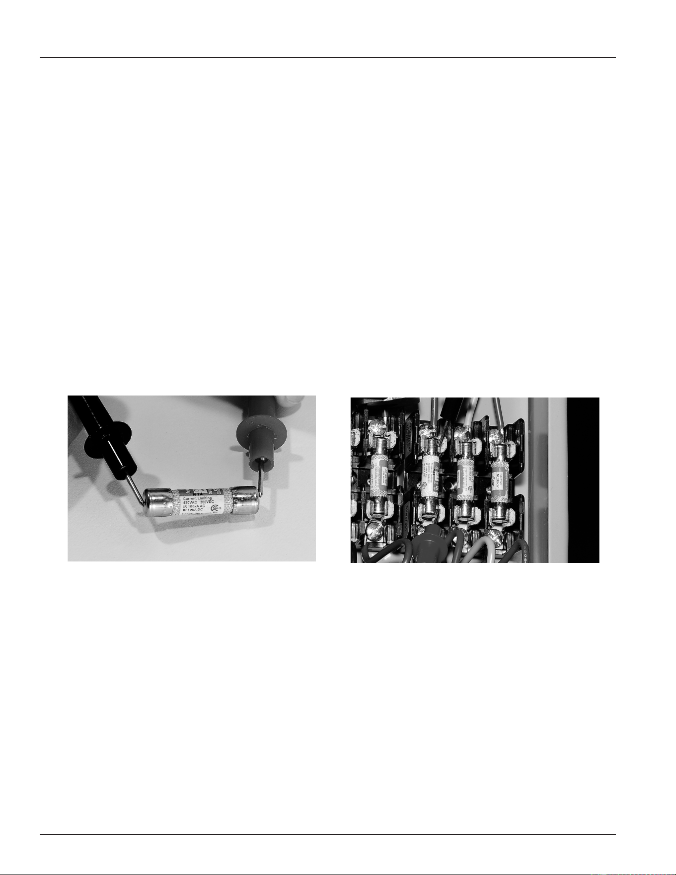
OHMMETER METHOD
1. Secure power to the water heater at the main breaker or disconnect switch.
2. Remove each fuse to be tested with an insulated fuse puller.
3. Set the ohmmeter to it’s lowest resistance range (< 200) or to an audible beep continuity test setting if so
equipped.
4. Touch the meter probes to both ends of each fuse simultaneously.
5. If the fuse being tested shows a low resistance (< 1 ohms) or the continuity test feature sounds an audible
beep the fuse being tested is good and can be re-installed.
6. If the fuse being tested shows innite resistance (open circuit) or the continuity test feature does not sound
an audible beep the fuse being tested is blown and must be replaced.
Figure 10. Fuse Test - Ohmmeter Method
Figure 11. Fuse Test - Volt Meter Method
VOLT METER METHOD
Fuses can also be checked using an AC volt meter. The power supply must be turned on and a call for heat
must be active (all thermostats/contactors must be closed) during this test. Touch the two test probes to both
ends of each fuse while still in its fuse blocks.
• A high voltage (at or above 120 VAC) reading indicates the fuse is blown.
• A zero volt reading generally indicates the fuse is good. Next check for voltage between each end of the
fuse and ground to ensure voltage is present at both ends of the fuse. If no voltage is present between
either end of the fuse and ground, the test has not been conclusive. Secure power to the water heater
and perform the ohmmeter test method described above.
The voltage test method is a good way to quickly identify fuses that are blown but it is not always conclusive
due to the dependence on power being present at both ends of the fuse, the switch contacts in thermostats/
contactors being closed, and correct wiring. Keep this in mind as there may be times when a fuse that is
blown tests good due to one of these dependencies not being met. The ohmmeter method described above
is 100% conclusive.
Printed on 6/17/2020 12:05 PM CT
19
Servicing should only be performed by a Qualied Service Technician
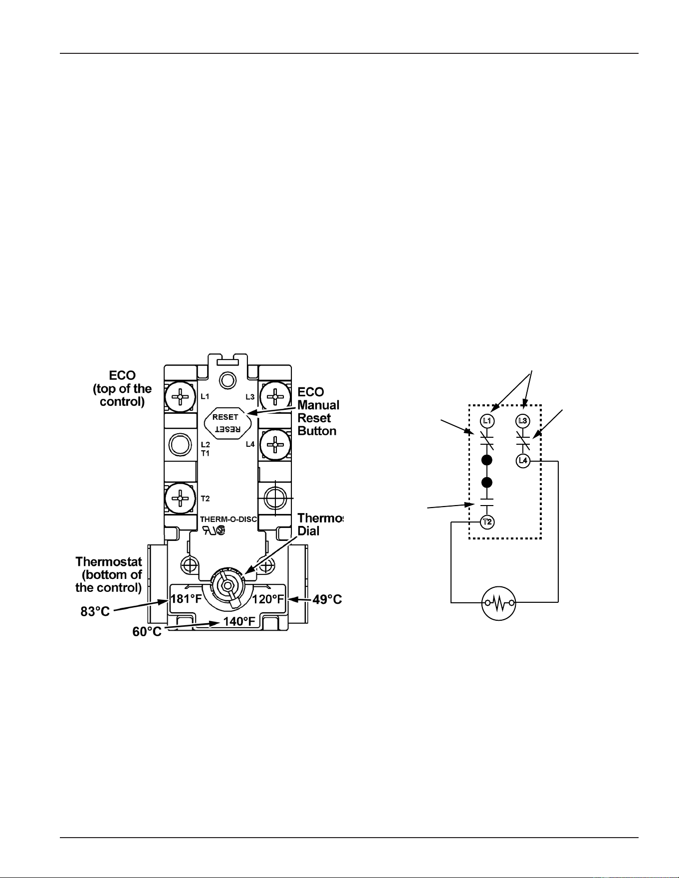
SURFACE MOUNT THERMOSTATS
The Surface Mount Control Model water heaters covered in this manual have “separate” thermostat/ECO
(energy cut out) combination controls mounted to the surface of the storage tank directly above the heating
elements they control. IE: a water heater equipped with 9 heating elements will have 9 thermostat/ECO
controls. These controls contain two bimetal thermal switches that react to heat sensed from the surface of
the water heater’s storage tank.
Thermostat: The thermostat portion of these controls is an automatic SPST (single pole single throw) switch
- see the Internal Wiring illustration below. As the tank (water) temperature rises and falls each individual
thermostat will de-energize (contact opens) and energize (contact closes) one heating element according to
it’s temperature setting. The temperate setting is adjustable using the dial on the lower portion of the control.
The adjustable range is 120°F/49°C to 180°F/82°C. The factory default setting is 140°F/60°C.
ECO: The ECO portion of these controls is a manual reset DPDT (double pole double throw) switch - see
the Internal Wiring illustration below. The ECO is a high temperature limit switch designed to protect against
excessively high water temperatures that can be caused by defective thermostats and grounded heating
elements. The ECO temperature setting is non adjustable and xed at 200°F/93°C. If the ECO activates
(contacts open) in response to abnormally high temperatures the contacts will not close automatically, the
ECO must be manually reset by pressing the red button on the top of the control. The tank temperature must
cool to approximately 120°F/49°C before the ECO can be reset. When activated (contacts open) the ECO will
interrupt all power supplied to the thermostat portion of the control and the heating element.
L3
L4
T2
L1
ECO DPDT
Contact
s
Thermostat
SPST Contacts
Power Supply to L1
and L3 Terminals
ECO DPDT
Contacts
Figure 12. Thermostat/Eco Front View Figure 13. Thermostat/Eco Internal Wiring
Printed on 6/17/2020 12:05 PM CT
20
Servicing should only be performed by a Qualied Service Technician
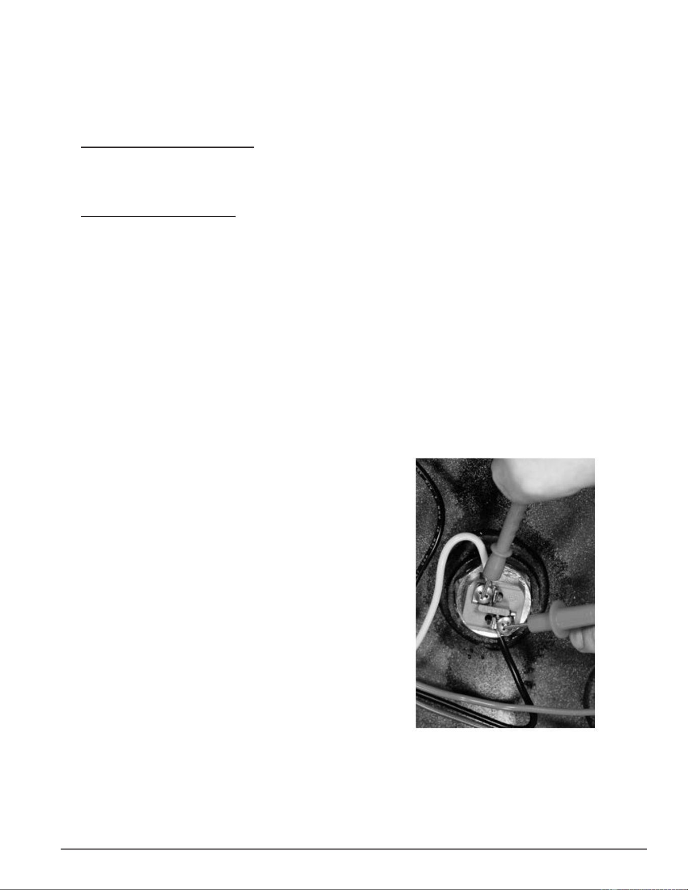
THERMOSTAT & ECO TEST
1. Secure power to the water heater at the main breaker or disconnect switch.
2. Ensure tank temperature is less than 100°F/38°C - dump water to lower tank temperature if necessary.
3. Press the red reset button rmly on all thermostat/ECO controls.
4. Raise the temperature setting on all thermostat/ECO controls to 140°F or higher.
5. Restore power to the water heater.
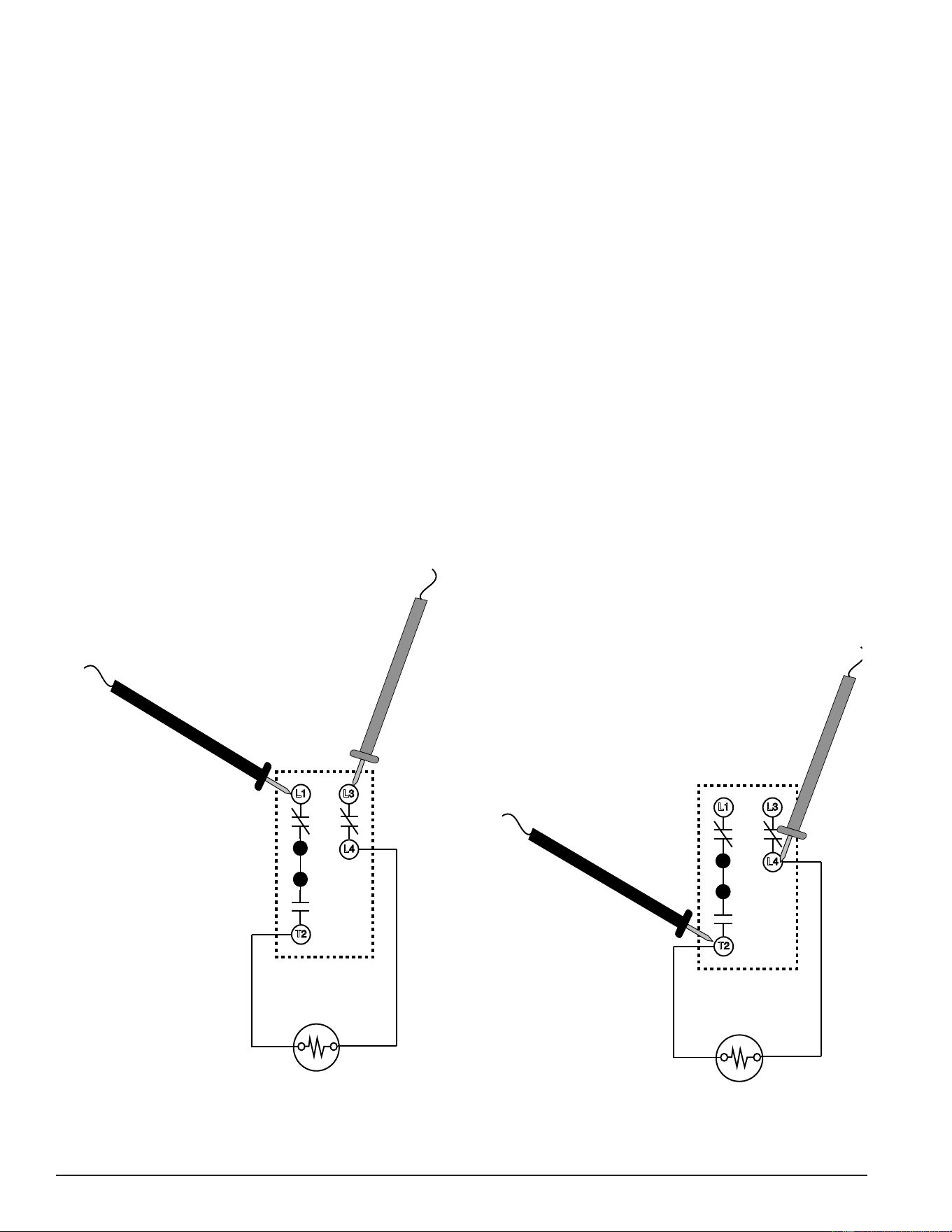
6. With an AC volt meter check for voltage between the L1 and L3 terminals on the control - see illustrations
below. Measured voltage should match the power supply to the water heater.
Service Note: If the measured voltage is zero volts or not the correct voltage ensure heating element
power circuit wiring is correct (see wiring diagram on water heater) check fuses (page 17)
and/or restore power to the water heater - see pages 12 - 14.
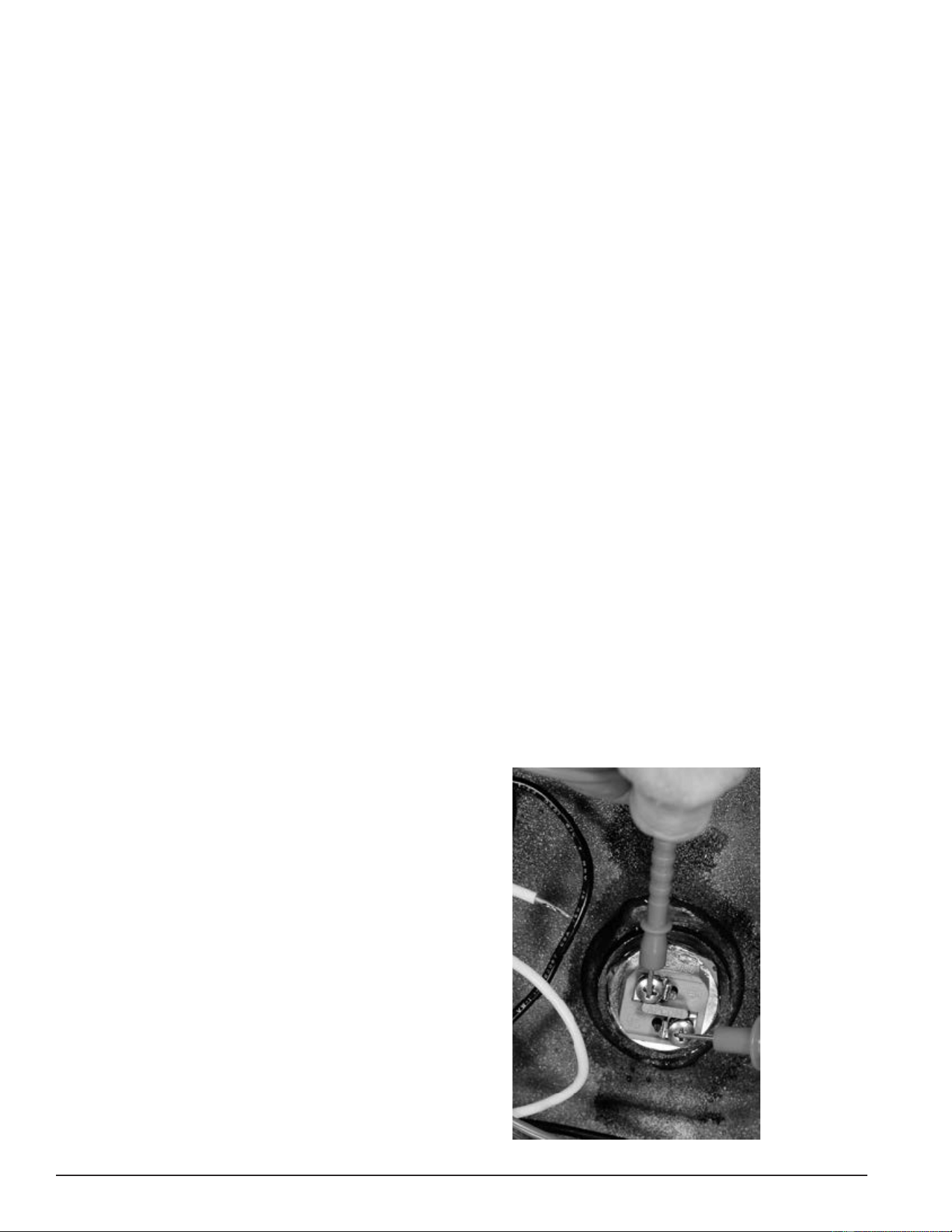
7. With an AC volt meter check for voltage between the L4 and T2 terminals on the control - see illustrations
below - if the measured voltage matches the power supply to the water heater the ECO is resetting properly.
If the measured voltage between L4 and T2 is low or not present the control is defective - replace the control.
Service Note: Grounded heating elements, defective thermostats and/or a defective ECOs can all cause
frequent ECO activation. If an ECO is being frequently reset on any of the thermostat/ECO
controls check all heating elements to ensure they are not grounded (see page 26) rst.
Replace any grounded elements. If no elements are grounded replace the thermostat/ECO
control(s) that require frequent resetting.
L3
L4
T2
L1
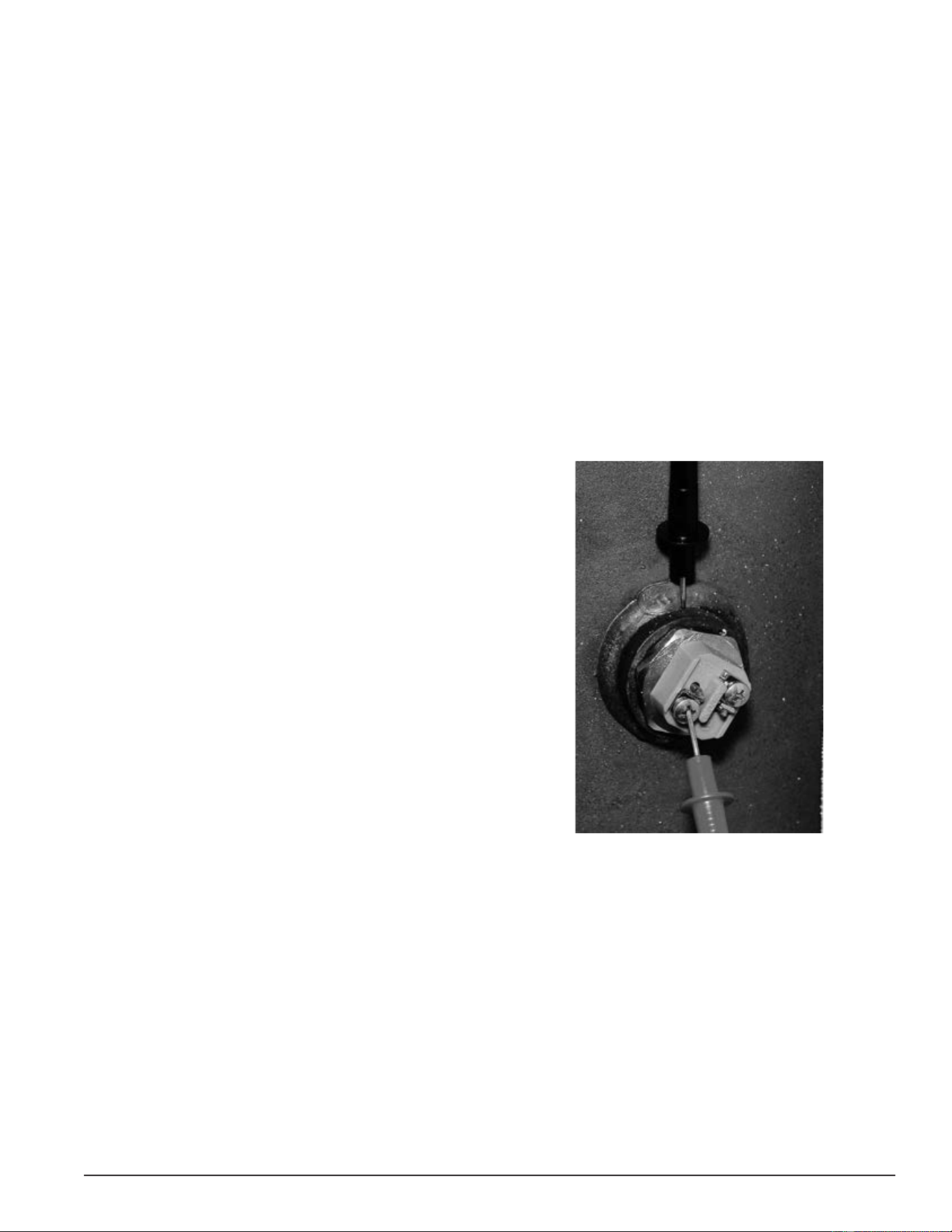
Figure 14. Step 6: Checking Power to the Control
L3
L4
T2
L1
Figure 15. Step 7: Checking Power to the Heating Element
Printed on 6/17/2020 12:05 PM CT
21
Servicing should only be performed by a Qualied Service Technician
HEATING ELEMENTS
This section of the manual provides information on how to determine the actual voltage and wattage rating
of a heating element along with tables showing heating element congurations, heating element amperage
and heating element resistance/ohms.
This section also contains heating element test procedures to measure; amperage, voltage, resistance and
check for grounded elements. These procedures are used to determine if a heating element is defective or
working properly. An AC amp meter, AC volt meter and ohmmeter are required. See Tools Required (page 4).
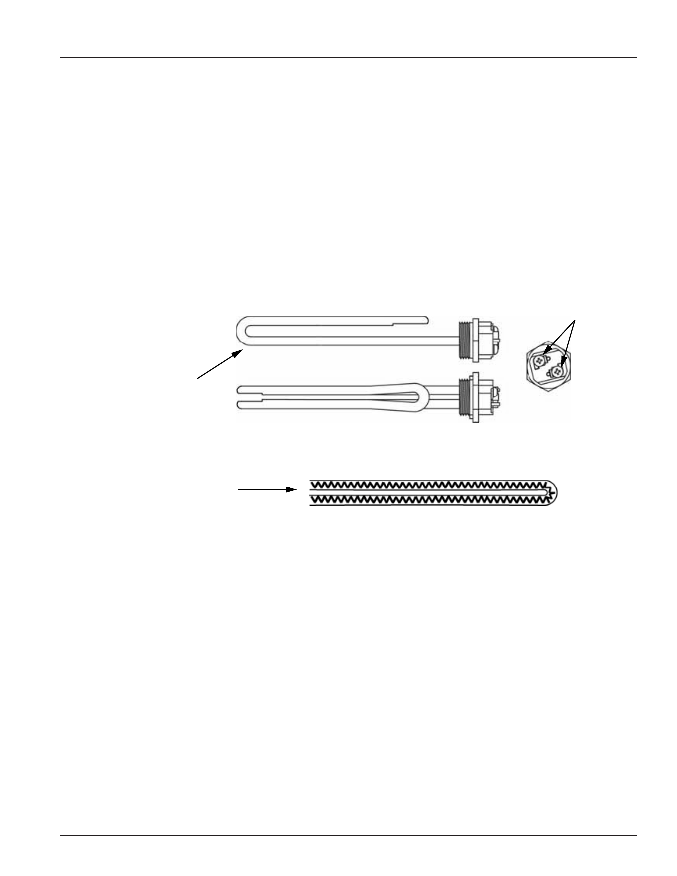
HEATING ELEMENT CONSTRUCTION
The water heater(s) covered in this manual use electric heating elements to heat water. Heating elements
convert electrical energy into heat energy.
Heating elements are constructed with metal tubing. Inside the tube is a wire conductor surrounded by an
insulating material. The wire conductor inside the heating element has a relatively high resistance to the ow
of electricity. Heat is generated when the electricity (voltage) applied to the heating element begins to ow
(amperage) and encounters the resistance (ohms) of the wire conductor inside.
Heating Element tube
encloses wire conductor
and insulating material.
Side View
Top View
Wiring
Terminals
Internal View Heating Element Tube
Wire conductor
inside tube
Figure 16. Heating Element Construction
Printed on 6/17/2020 12:05 PM CT
22
Servicing should only be performed by a Qualied Service Technician
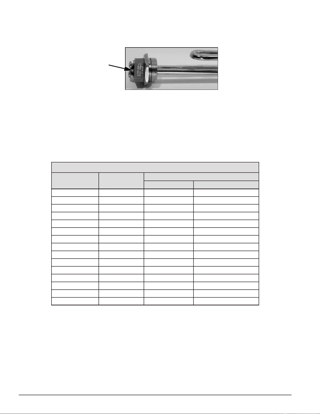
HEATING ELEMENT RATINGS
Heating elements are labeled with their voltage and kW rating. See Figure 17. The element shown here is a
6000 watt (6 kW) 240 volt element.
Wattage
and
Voltage
Ratings
Figure 17. Heating Element Rating Label
Note: Some heating elements are dual rated elements. For example, 208/240 volts.
HEATING ELEMENT CONFIGURATIONS
Table 1 shows how many heating elements are installed at the factory and the wattage of each heating element
according to the rated voltage of the water heater. The table below represents all available tank sizes; 50, 80
and 120 gallon models.
Service Note: 208-volt 18-kW models are only available with six 3000 watt elements and 208-volt 36-kW
models are only available with nine 4000 watt heating elements.
Table 1. Standard Heating Element Congurations
Total Water Heater
Input (kW)
Heating Element
Wattage
Number of Factory Installed Heating Elements
208 VAC 240/277/480 VAC
6 2000 3 3
9 3000 3 3
12 4000 3 3
13.5 4500 3 3
15 5000 3 3
18 6000 N/A 3
18 3000 6 6
24 4000 6 6
27 4500 6 6
30 5000 6 6
36 6000 N/A 6
36 4000 9 9
40.5 4500 9 9
45 5000 9 9
54 6000 9 9
Printed on 6/17/2020 12:05 PM CT

23
Servicing should only be performed by a Qualied Service Technician
HEATING ELEMENT AMPERAGE
This table shows the approximate amp draw for the various heating elements used. First determine the
actual rated wattage and voltage of the element being tested. See Heating Element Ratings (page 22). Then
follow the Heating Element Amperage Test (page 24) to measure amperage at each heating element. Compare
the measured value to the values in the table below. Keep in mind there may be some variance between
measured values and the values in this table due to uctuations in voltage, temperature and the calibration
of test instruments being used.
Table 2. Approximate Current - Amps
Element Wattage
Approximate Current Amps
208 VAC 240 VAC 277 VAC 480 VAC
2000 9.62 8.33 7.22 4.17
3,000 14.42 12.50 10.83 6.25
4000 19.23 16.67 14.44 8.33
45000 21.63 18.75 16.25 9.38
5000 24.04 20.83 18.05 10.42
6,000 28.85 25.00 21.66 12.50
Service Note: Correct Elements: If the measured amp draw on any element is considerably less or more
than the values given in the table above, check the element rating to ensure it matches
the water heater’s factory conguration. See Heating Element Ratings and Heating Element
Congurations (page 22). All heating elements should have the same voltage and kW rating
in a water heater. If an element does not have the correct rating for the water heater being
serviced, it must be replaced with a properly rated heating element.
Service Note: Grounded Elements: Grounded elements on surface mount control models, Figure 1 (page
9), can draw low amps because power is continuously present at one terminal on each
element. See Figure 13 (page 19). Power from the thermostat’s L4 terminal is always
present at each element and can ow from a grounded element through the water to the
storage tank. If the measured amps are considerably less than the values in the table above,
test those elements for grounding. See Heating Element Resistance & Ground Tests (page 26).
Heating Element Resistance
This table shows the approximate resistance (in ohms) for the various heating elements used. First determine
the actual rated wattage and voltage of the element being tested - see Heating Element Ratings on page
21. Then follow the Heating Element Resistance Test procedure (page 26) to measure the resistance of each
heating element. Compare the measured value to the values in the table below. Keep in mind there will be
some variance between measured values and the values in this table due to uctuations in temperature and
the calibration of test instruments being used.
Table 3. Element Resistance
Total
Element Wattage
Approximate Resistance - Ohms
208 VAC 240 VAC 277 VAC 480 VAC
2000 21.63 28.80 38.36 115.20
3,000 14.42 19.20 25.58 76.80
4000 10.82 14.40 19.18 57.60
4500 9.61 12.80 17.05 51.20
5000 8.65 11.52 15.35 46.08
6,000 7.21 9.60 12.79 38.40
Printed on 6/17/2020 12:05 PM CT
24
Servicing should only be performed by a Qualied Service Technician
Heating Element Amperage Test
This test should be considered as a rst diagnostic procedure for the common service complaints of no hot
water or not enough hot water. The heating element amperage test shown on this page is the best procedure
to quickly determine which (if any) heating elements are not working properly.
1. Secure power to the water heater at the main breaker or disconnect switch.
2. Ensure tank temperature is less than 100°F/38°C - dump water to lower tank temperature if necessary.
3. Surface Mount Control Models: Raise the temperature settings to ensure a call heat is active for all heating
elements. Press the red reset button rmly on all thermostat/ECO controls. Raise the temperature setting
on all thermostat/ECO controls to 140°F or higher. See Surface Mount Thermostats (page 19).
4. Restore power to the water heater.
5. Electronic Control Models: Adjust the temperature settings to ensure a call for heat is active for all heating
elements. Raise the Operating Set Point in the Temperatures menu to 140°F or higher. Set all Heating Element
Bank Differentials in the Temperatures menu to 2°F. See Temperatures Menu (page 53).
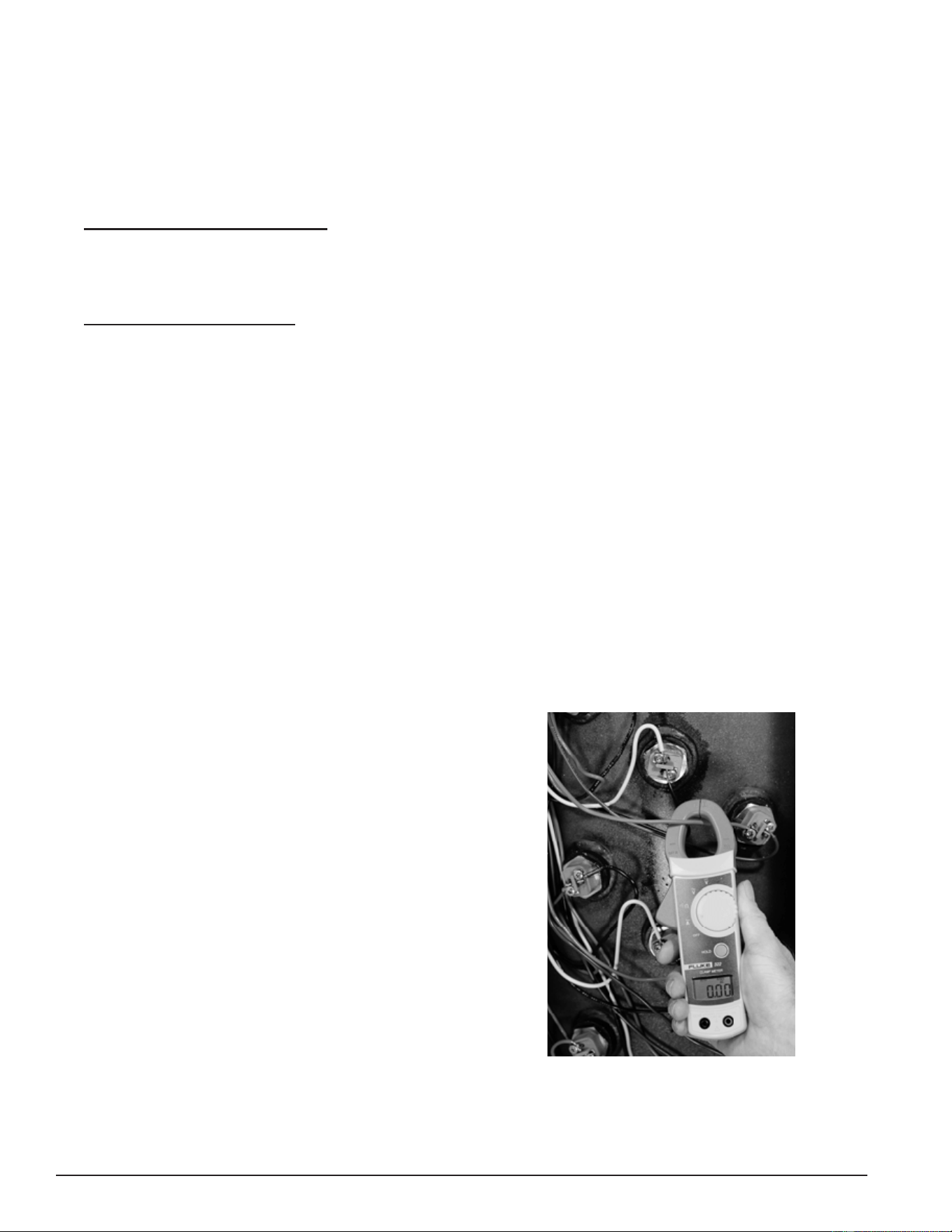
6. Using a clamp style AC amp meter: set the amp meter to an AC amperage range just above the expected
amperage (100 AC amp range initially). Measure and record the amperage at all heating elements by clamping
the jaws of the meter around ONLY one of the wires to each heating element. See the image below. Heating
element amp readings should be approximately the same for all heating elements. The normal operating
amps for all heating elements is provided in in Table 4 and Table 5 (page 35) or it can be calculated using
Ohm's Law. See Ohm's Law (page 12).
Service Note: Check all power circuit wiring to the heating element(s) on any element drawing zero or low
amps - see the wiring diagram on the water heater. On electronic control models, check the
contactors on any heating element(s) drawing zero or low amps. See Contactors (page 30).
Perform the Heating Element Voltage Test (page 25) and Heating Element Resistance & Ground Tests
(page 26) on any heating elements that are drawing zero amps or any heating element
drawing less than normal operating amps.
If the measured amp draw on any element is considerably less or more than the normal operating amps ensure
the voltage and kW rating of those heating elements is the correct value for the water heater being serviced.
See Heating Element Ratings and Heating Element Congurations (page 22).
Measuring amperage on an electric heating element.
Make sure the jaws of the AC amp meter are clamped
around ONLY ONE WIRE to each heating element at a
time. Clamping around more than one wire often gives
a false zero amp reading.
DO NOT TOUCH THE ENDS OF ANY HEATING
ELEMENTS WHILE PERFORMING THIS TEST
Be extremely careful as there will be high voltage
present at the wiring terminals on all heating elements
during this test.
Figure 18. Heating Element Amperage Test
Printed on 6/17/2020 12:05 PM CT
25
Servicing should only be performed by a Qualied Service Technician
Heating Element Voltage Test
This test is typically performed after an amperage test has determined one or more heating elements (or
heating element loops) is not drawing the correct amperage. See Heating Element Amperage Test (page 24).
1. Secure power to the water heater at the main breaker or disconnect switch.
2. Ensure tank temperature is less than 100°F/38°C - dump water to lower tank temperature if necessary.
3. Surface Mount Control Models: Raise the temperature settings to ensure a call heat is active for all heating
elements. Press the red reset button rmly on all thermostat/ECO controls. Raise the temperature setting
on all thermostat/ECO controls to 140°F or higher. See Surface Mount Thermostats (page 19).
4. Restore power to the water heater.
5. Electronic Control Models: Adjust the temperature settings to ensure a call heat is active for all heating
elements. Raise the Operating Set Point in the Temperatures Menu to 140°F or higher. Set all Heating
Element Bank Differentials in the Temperatures Menu to 2°F. See Temperatures Menu (page 53).
6. Using an AC volt meter; set the volt meter to an AC voltage range above the expected voltage (600 VAC or
higher range initially).
7. Check voltage between the two terminals on the heating element. See Figure 19. Record the voltage at all
heating elements. Voltage should match the listed voltage on the water heater’s rating label.
8. If the measured voltage is zero volts or is not the correct voltage, check power to the water heater. See
Checking Three Phase (3Ø) Power (page 15). Check fuses; see Fuses (page 18). Ensure heating element
power circuit wiring is correct. (See the wiring diagram on water heater.) Check thermostat/ECO control(s)
supplying power to the heating element on surface mount control models. See Thermostat & ECO Test (page 20).
Check contactors on electronic control models. See Contactors (page 30).
Check all wiring and connections between the heating elements, contactors, fuses and the power distribution
block. Ensure all wiring and connections are tight and making good contact. Replace any wiring, fuses
and/or contactors that are not working properly, damaged, or show signs of excessive wear.
Measuring voltage on an electric heating element. Touch
the two volt meter probes to the two terminals on the
end of each heating element.
DO NOT TOUCH THE ENDS OF ANY HEATING
ELEMENTS WHILE PERFORMING THIS TEST
Be extremely careful as there will be high voltage
present at the wiring terminals on all heating elements
during this test.
Figure 19. Element Voltage Test
Printed on 6/17/2020 12:05 PM CT
26
Servicing should only be performed by a Qualied Service Technician
Heating Element Resistance & Ground Tests
This is a two part test. In the rst part of this test, the actual resistance (ohms) of each heating element is
measured. In the second part of this test, each heating element is tested for any continuity to ground to
ensure that the heating element is not shorted to ground. These tests should be considered as third and fourth
diagnostic procedures to be performed whenever the results from the Heating Element Amperage Test showed a
heating element was not drawing the correct amps AND the results from the Heating Element Voltage Test showed
the element had the proper voltage applied.
Heating Element Resistance Test
1. Determine what the actual voltage and kW rating is for the heating elements in the water heater being
serviced. See Heating Element Ratings and Heating Element Congurations (page 22). Replace any elements that
are not the proper rating for the water heater being serviced before proceeding.
2. Secure power to the water heater at the main breaker or disconnect switch.
3. Verify with an AC volt meter that there is not any voltage present at the power distribution block. See Figure 1
(page 9) or Figure 2 (page 10). Verify also that there is not any voltage present at the two wiring terminals
on the ends of all heating elements.
4. Disconnect both power wires from the contactor(s) to all elements being tested.
5. Using an ohmmeter: set the ohmmeter to a range just above the expected ohms (200 ohm range initially).
6. Touch the ohmmeter probes between the two terminals on each heating element - see the image below.
Measure and record the resistance (ohms) at all heating elements being tested.
7. Compare the resistance value (ohms) measured to the values given in Table 3 (page 23).
8. If the measured resistance (ohms) matches the values in the Table 3 (page 23), the heating element
resistance is correct.
9. If the resistance reading is innite--no continuity at all between the two terminals--the heating element is
defective and must be replaced. During heating element replacement, be sure to do the following:
• Check fuses; see Fuses (page 18).
• Inspect contactors on electronic control models. See Contactors (page 30).
• Check all wiring and connections between the heating elements, contactors, fuses and the power
distribution block. Ensure all wiring and connections are tight and making good contact. Replace any
wiring, fuses, contactors that are damaged or show signs of excessive wear.
Measuring resistance (ohms) on an electric heating
element. Touch the two ohmmeter probes to the two
terminals on the end of each heating element.
Figure 20. Element Resistance (ohms) Test
Printed on 6/17/2020 12:05 PM CT
27
Servicing should only be performed by a Qualied Service Technician
Heating Element Ground Test
1. Secure power to the water heater at the main breaker or disconnect switch.
2. Verify with an AC volt meter that there is not any voltage present at the power distribution block and at the
two wiring terminals on the ends of all heating elements. See Figure 1 (page 9) and Figure 2 (page 10).
3. Disconnect both power wires from the contactor(s) to all elements being tested.
4. Using an ohmmeter: set the ohmmeter to one of it’s lowest resistance ranges - 200 ohms or less initially. An
audible beep continuity test setting can also be used on ohmmeters so equipped.
5. Touch one of the ohmmeter probes to one of the two heating element wiring terminals and the other probe to
a grounded surface on the water heater such as the water heater’s storage tank (use sand cloth if necessary
to remove any coating that may prevent metal to metal contact) or the water heater ground wire connection.
Check between the other heating element terminal and ground also - see the image below.
6. If there is innite resistance - no continuity - between both heating element wiring terminals and ground the
heating element(s) is not grounded.
7. If there is any resistance measured - there is continuity - between either heating element wiring terminal
and ground the heating element is defective and must be replaced. Ensure the voltage and KW rating of the
replacement heating element is the correct rating for the water heater being serviced. See Heating Element
Ratings and Heating Element Congurations (page 22).
Checking an electric heating for any resistance or
continuity to ground. Touch one of the ohmmeter probes
to one terminal on the end of a heating element and the
other probe to a grounded surface on the water heater.
Figure 21. Element Resistance (ohms) Test
REPLACING HEATING ELEMENTS
1. Secure power to the water heater at the main breaker or disconnect switch.
2. Verify with an AC volt meter that there is not any voltage present at the power distribution block. See Figure
1 (page 9) and Figure 2 (page 10). Verify also that there is not any voltage present at the two wiring
terminals on the ends of all heating elements.
3. Disconnect both power wires from the terminals on the top all heating elements being replaced.
4. Drain the water heater - follow the draining instructions in the Maintenance section of the instruction manual
that came with the water heater. If the instruction manual is not available, copies can be obtained from the
manufacturers web site or by calling the toll free phone number on the back cover of this manual.
5. Remove/install heating elements using a 1 1/2” six point socket. Install a new heating element gasket with
the new element. Replacement elements and gaskets can be obtained from local distributors or by calling
the toll free phone number on the back cover of this manual.
Printed on 6/17/2020 12:05 PM CT
28
Servicing should only be performed by a Qualied Service Technician
ELEMENT SENSORS
The electronic control models covered in this manual monitor all heating elements using element sensors.
Each element sensor monitors three heating elements. There is one element sensor for each bank of heating
elements. See Figure 2 (page 10) and Contactor Congurations (page 31). Water heaters equipped with three
heating elements will have one element sensor, water heaters equipped with six elements will have two element
sensors, and water heaters equipped with nine elements will have three element sensors.
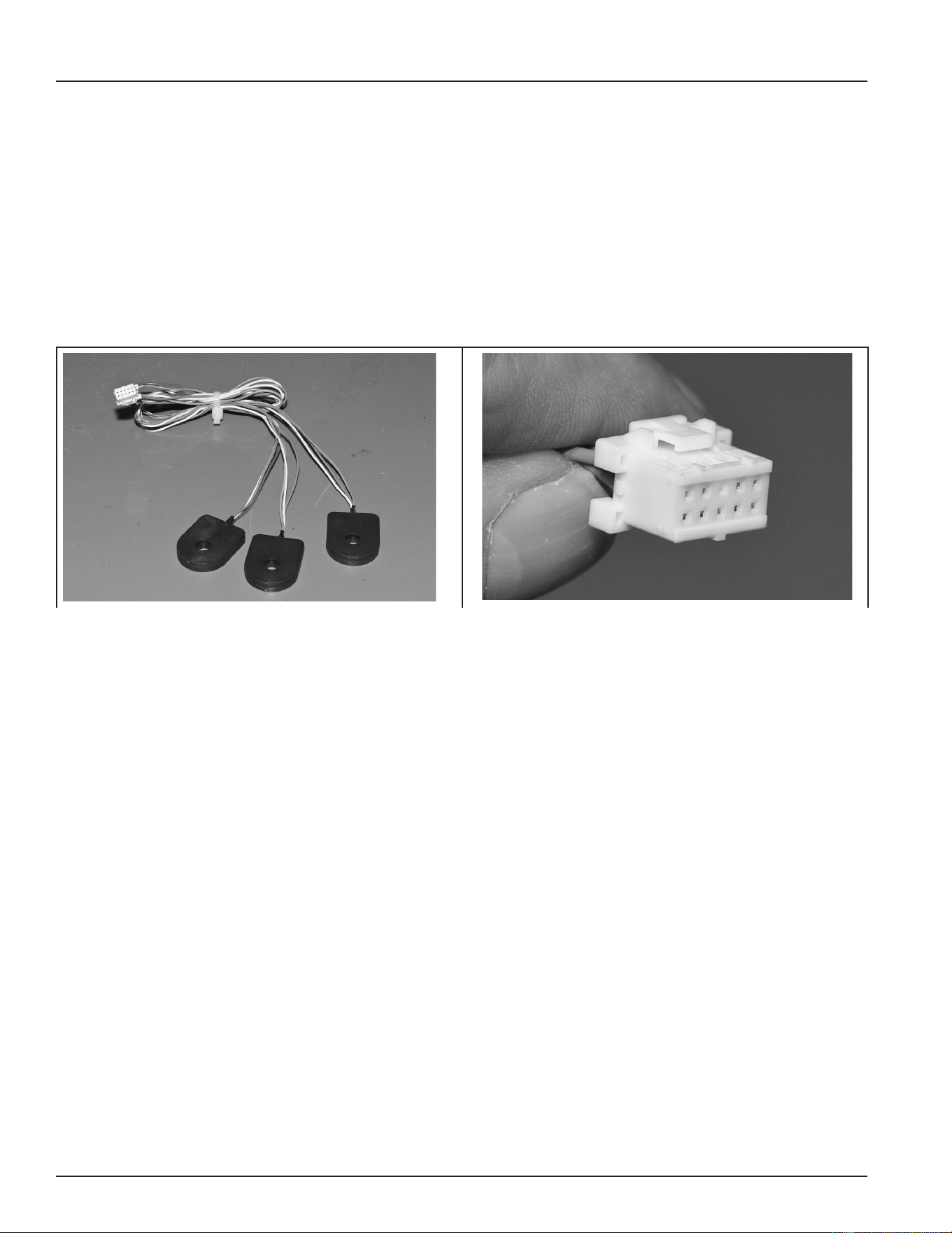
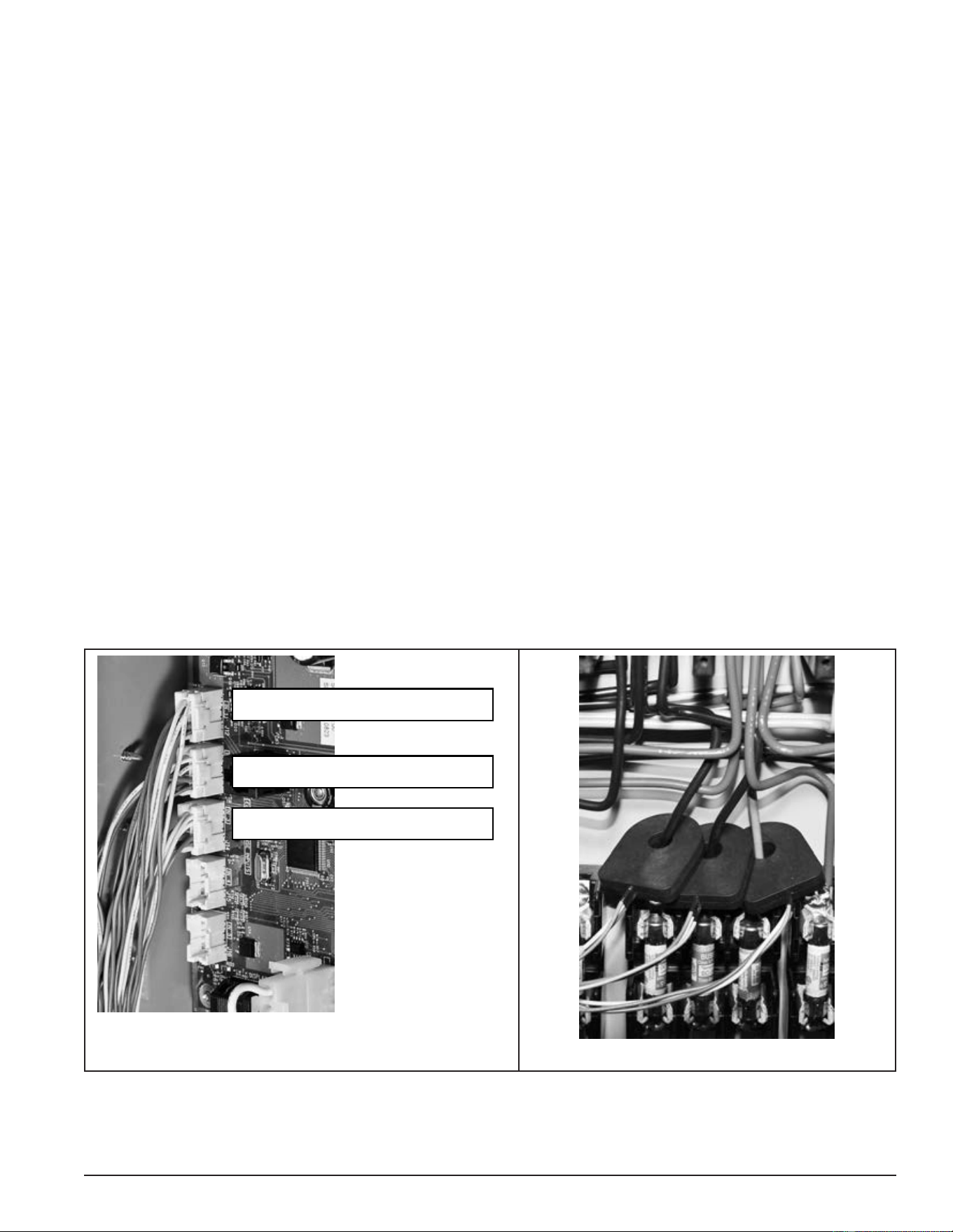
ELEMENT SENSOR CONSTRUCTION
Element Sensors consists of three individual current sensors, a ten-conductor plug, and nine wires that connect
between the individual current sensors and the plug. Each current sensor monitors one heating element.
Current sensors are enclosed in a black plastic housing that has a hole in the middle. One power wire to each
heating element is routed through the hole in one of the current sensors. See the images below.
Figure 22. Element Sensor Figure 23. Ten-Conductor Plug
ELEMENT SENSOR FUNCTIONS
Working with the element sensors, the electronic control system provides valuable operational and diagnostic
information to aid in servicing:
• The electronic control system displays animated Status Icons on the user interface module (UIM)
to indicate which heating elements are being energized and which heating elements are not being
energized. The Status Icons are also capable of indicating when a heating element that should be
energized is not drawing current/amps. See the status icons in Table 12 (page 51).
• The electronic control system displays a “No Current Detected” alert message on the UIM if the control
system does not sense current (amperage) from a heating element when expected. See User Interface
Module (UIM) (page 48). For example, a call for heat is active, all contactor coils have been energized,
and the control system is not sensing current from one or more heating element. See Electronic Controls
(page 42) and Fault And Alert Messages (page 69).
• During alert conditions, the control system allows the water heater to continue heating (other elements
may still be working), but prompts the user to have the water heater serviced.
Printed on 6/17/2020 12:05 PM CT
29
Servicing should only be performed by a Qualied Service Technician
ELEMENT SENSOR OPERATION
When current (amperage) ows through a wire in an electrical circuit a magnetic eld is developed that radiates
out from the wire. The individual current sensors detect this magnetic eld. When current ows in a wire routed
through the hole in one of the individual current sensors, the sensor is activated and sends a signal back to
the CCB conrming the presence of current.
The current sensors require approximately 3 AC amps minimum to activate. An active signal from a current
sensor indicates only the current has been sensed; it DOES NOT indicate the amount or level of current is
correct for a given heating element.
As explained on the previous page, element sensors contain three individual current sensors. The three
current sensors are installed just above the power circuit fuse blocks. One heating element power wire is
routed through the hole in one sensor.
The plug from each element sensor plugs into one of three sockets on the CCB. The J12, J13, and J14 sockets
are for heating element Banks 1, 2, and 3 respectively, depending on how many elements are installed in the
water heater. See Figure 24 and Figure 25.
Service Note: The element sensors cannot be serviced in the eld. If it is determined one of the three
individual current sensors in an element sensor assembly is defective, the entire assembly
must be replaced. If the correct amperage through a heating element has been veried with
an AC amp meter Heating Element Amperage Test (page 24) and the current sensor for that
element does not activate and send a signal to the CCB, do the following:
• Ensure the element sensor plug and socket connection is making good contact.
• On models equipped with two or three banks of heating elements, secure power to the water heater and
try switching Element Sensor plugs between the J12, J13, and J14 sockets to verify that the element
sensor is defective. A “No Current Detected” Alert message and Status Icon indication should “follow”
the defective element sensor and report that a different heating element is not drawing current when
current is expected.
J12 Heating Element Bank 1
J13 Heating Element Bank 2
J14 Heating Element Bank 3
]
Figure 24. CCB Element Sensor Sockets
Figure 25. Heating Element Wire Routing
Printed on 6/17/2020 12:05 PM CT
30
Servicing should only be performed by a Qualied Service Technician
CONTACTORS
This section of the manual provides information on how contactors used on electronic control models are
constructed, how they work, and how to test contactor operation. See Figure 2 (page 10) for the location of
the contactors on these models. Surface-mount control models are not equipped with contactors.
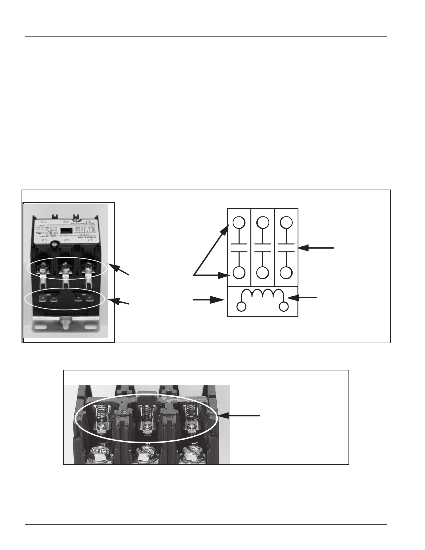
CONTACTOR CONSTRUCTION - HOW THEY WORK
Magnetic contactors are used on Electronic Control Models to energize and de-energize the heating elements.
Power from the fuse blocks is supplied to the heating elements through three switches (3 poles) inside the
contactor. Springs located inside the contactor hold the switch contacts open; the springs are compressed
and the spring tension forces or holds the switch contacts in their normally open state.
The contactor’s switches are closed by an electromagnetic coil inside the base of the contactor. When a call
for heat is activated the electronic control system sends 120 volts to the contactor’s electromagnetic coil. As
current runs through the coil it becomes “magnetized” and overcomes the spring tension holding the switch
contacts open. The switch contacts then close which in turn sends power to the heating elements. When
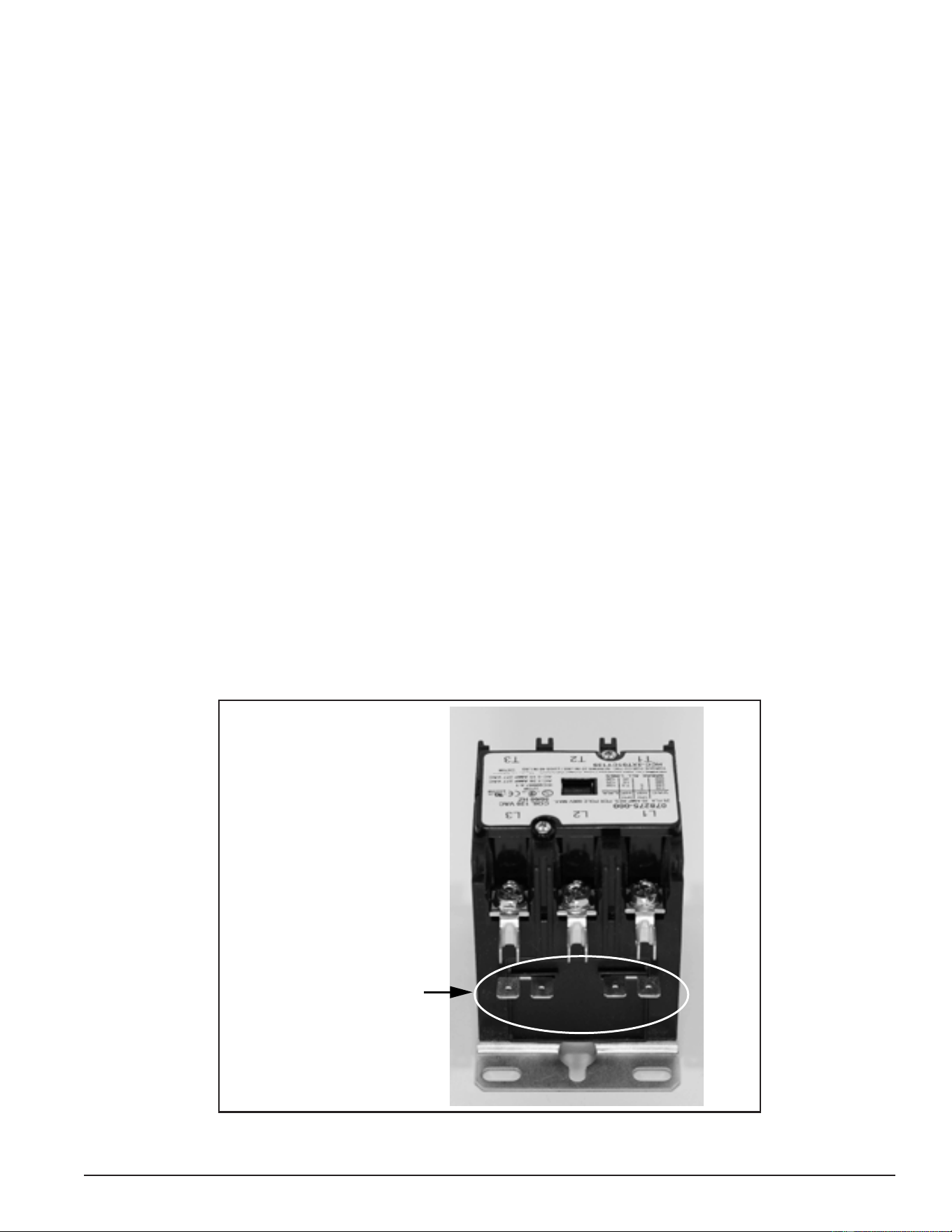
the call for heat is satised the control system de-energizes the contactor coil and spring tension returns the
contacts to their open position.
Heating
Element Power
Circuit Wiring
Terminals
Electromagnetic
Contactor Coil
Wiring Terminals
120 VAC
Electromagnetic
Contactor Coil
3 Normally
Open Switch
Contacts
3-Pole Contactor Side View
3-Pole Contactor Internal Wiring
T1T2
T3
L3
L2
L1
Figure 26. Three-Pole Contactor Wiring Side and Internal Views
3-Pole Contactor Side View - Cover Plate Removed
Contactor Springs Hold
Contacts Open When
Electromagnetic Coil Is
Not Energized
Figure 27. Three-Pole Contactor Side View - Cover Plate Removed
Printed on 6/17/2020 12:05 PM CT
31
Servicing should only be performed by a Qualied Service Technician
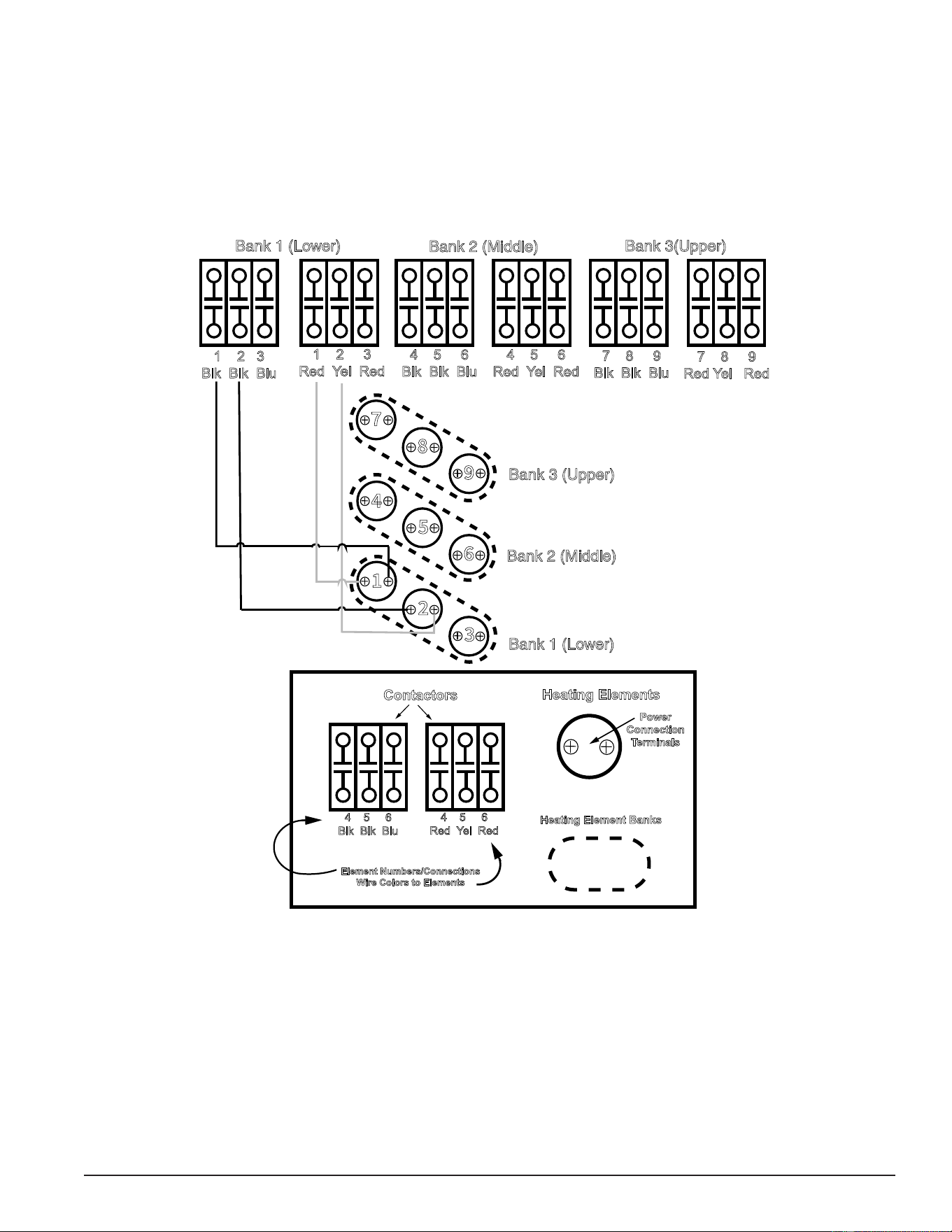
CONTACTOR CONFIGURATIONS
This illustration shows how contactors are congured and how they provide power to the heating elements
on Electronic Control Model water heaters, This is a redundant contactor conguration - two contactors must
close their contacts to energize any heating element. Elements and Banks are numbered according to how
the control system monitors them. See Element Sensors (page 28). There are two contactors installed for
each Bank. For example, the illustration shows a nine-element conguration, a water heater factory equipped
with six heating elements would have four contactors and a water heater with three elements would have two
contactors. For simplicity, wiring is shown for the rst two heating elements in Bank 1 only.
Bank 1 (Lower)
Bank 2 (Middle)
Bank 3(Upper)
Bank 1 (Lower)
Bank 2 (Middle)
Bank 3 (Upper)
1 2 3
Blk Blk Blu
1 2 3
Red Yel Red
4 5 6
Blk Blk Blu
4 5 6
Red Yel Red
7 8 9
Blk Blk Blu
7 8 9
Red Yel Red
Contactors
Heating Elements
Power
Connection
Terminals
Heating Element Banks
Element Numbers/Connections
Wire Colors to Elements
4 5 6
Blk Blk Blu
4 5 6
Red Yel Red
Legend
Figure 28. Contactor Congurations
Printed on 6/17/2020 12:05 PM CT
32
Servicing should only be performed by a Qualied Service Technician
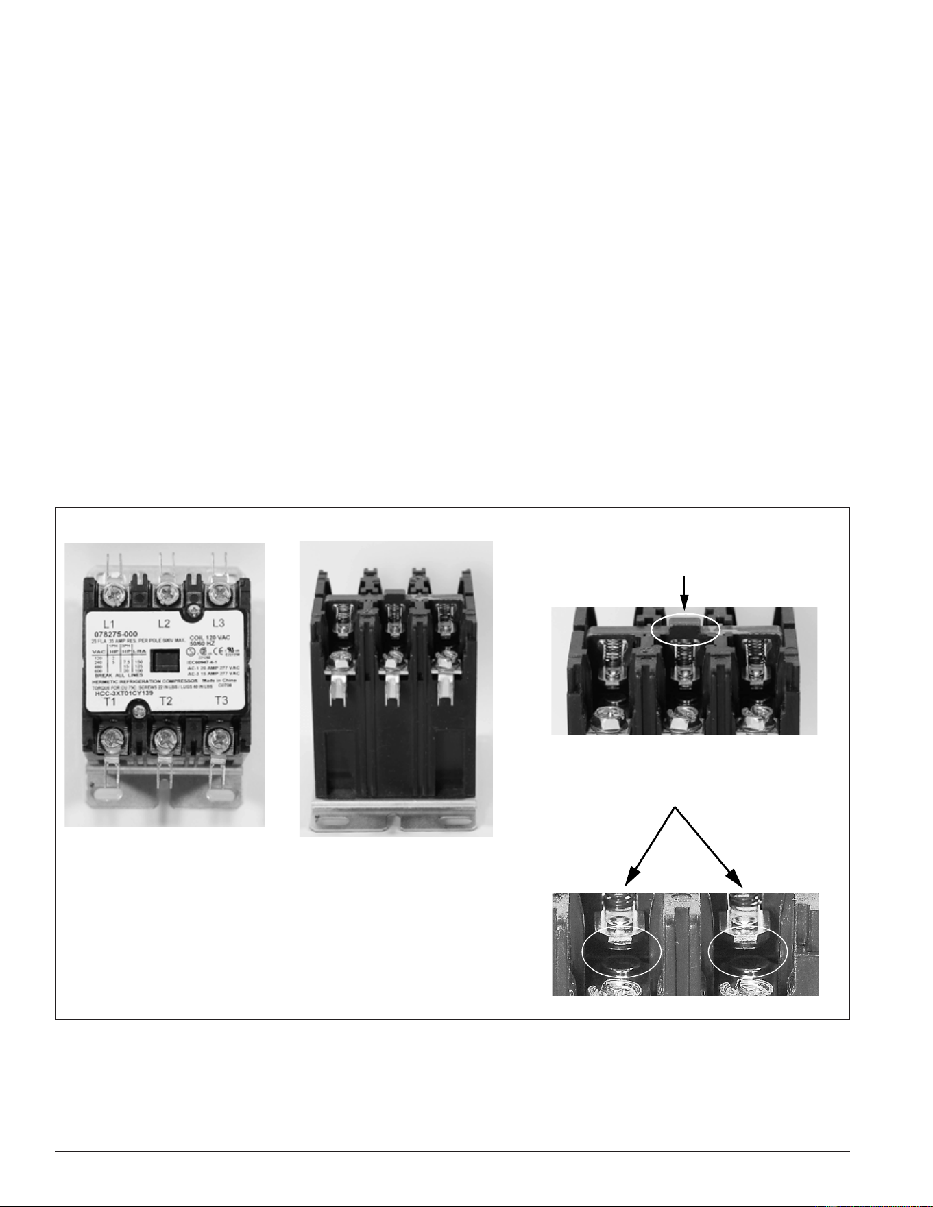
CONTACTOR INSPECTION
A thorough visual inspection of the contactors used on electronic control models should be performed as part
of any regular maintenance program and whenever the water heater is being serviced. Refer to the listed
steps and Figure 29 for this procedure.
1. Secure power to the water heater at the main breaker or disconnect switch.
2. Verify with an AC volt meter that there is not any voltage present at the power distribution block, power
circuit fuse block and all wiring terminals on the contactors. See Figure 2 (page 10) for the location of these
components.
3. Remove the top cover (two small screws) from the contactor.
4. Check for and remove any debris from the area surrounding the switch contacts. For example, ants will
occasionally infest the switch contacts and eventually cause the contactor to malfunction.
5. Physically test the mechanical spring action of the contactor by depressing the contactor mechanism. If the
action is not smooth and/or sticks, replace the contactor.
6. Perform a close visual inspection of the switch contacts. The contacts are silver plated and should be smooth.
Contactor chatter (page 7), voltage spikes, arcing, and excessive current, along with normal wear and
tear, can cause the normally smooth surface of the contacts to become burnt, pitted and damaged. In extreme
cases, the contacts can “weld” closed. The switch contacts are not replaceable. If the contacts show signs
of excessive wear or damage, replace the contactor.
7. Replace the top cover on all contactors when inspection is complete.
3-Pole Contactor
Top View - Cover Plate ON
Side View - Cover Plate Removed
Physically Operate Mechanical
Spring-Action of Contactor
Press Down Here
Perform a Close Visual Inspection
of Switch Contacts
Figure 29. Perform Close Visual Inspection Of Switch Contacts
Printed on 6/17/2020 12:05 PM CT
33
Servicing should only be performed by a Qualied Service Technician
CONTACTOR COIL VOLTAGE TEST - AT CONTACTOR
This test procedure will measure contactor coil voltage at the contactor.
1. Ensure tank temperature is less than 100°F/38°C. Dump water to lower tank temperature if necessary.
2. Adjust the temperature settings to ensure a call for heat is active for all heating elements. Raise the Operating
Set Point in the Temperatures menu to 140°F or higher. Set all Heating Element Bank Differentials in the
Temperatures Menu to 2°F. See Temperatures Menu (page 53).
3. Using an AC volt meter, set the volt meter to an AC voltage range just above 120 VAC.
4. Touch the two volt-meter probes to the contactor coil wiring terminals on the contactor. Repeat this procedure
at each contactor being tested. There should be approximately 120 volts present between the two terminals.
If there is no voltage, proceed to Contactor Coil Voltage Test - At CCB (page 34).
Service Warning: Be extremely careful when performing this test procedure; volt meter probes are routed
between wires in tight proximity. There will be high voltage present at all terminals and
wiring to the contactors.
5. If the measured voltage is considerably less than 120 volts and/or the contactors chatter (open and close
rapidly), ensure the Control Circuit Transformer is wired correctly. See Transformers (page 35).
6. If the measured voltage is approximately 120 volts, the contactor should close it’s switch contacts. If the
contacts are closed, the contactor coil is operating properly.
7. If the measured voltage is approximately 120 volts and the contactor’s switch contacts do not close, the
contactor is defective and must be replaced. When replacing a contactor that has failed in this way, check
all wiring between the contactor coil and the J4 wiring terminals on the Central Control Board (CCB) (page 43)
for pinched or shorted wires. Repair or replace damaged wiring as necessary.
Service Note: A continuity test can also be performed on contactor coils to determine if the failure is due to
an open coil winding. Secure power to the water heater at the main breaker or disconnect
switch, disconnect both wires to the contactor coil, and check for continuity between the
two terminals using an ohmmeter. If a contactor has an open coil, the contactor must
be replaced. Check all wiring between the contactor coil and the J4 wiring terminals on
the Central Control Board (CCB) (page 43) for pinched or shorted wires. Repair or replace
damaged wiring as necessary.
3-Pole Contactor Side View
Electromagnetic
Contactor Coil Wiring
Terminals 120 VAC
Figure 30. Contactor Coil Wiring Terminals
Printed on 6/17/2020 12:05 PM CT
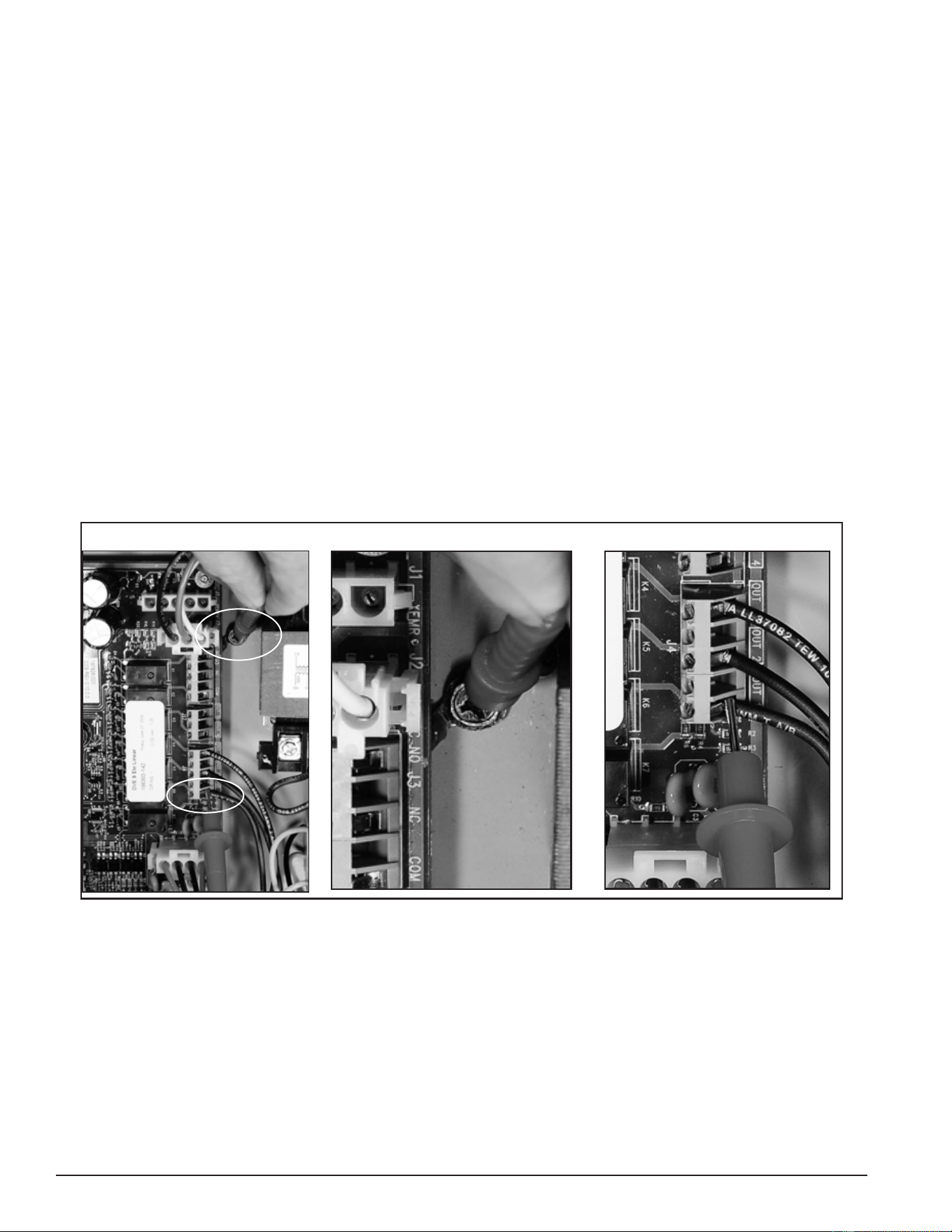
34
Servicing should only be performed by a Qualied Service Technician
CONTACTOR COIL VOLTAGE TEST - AT CCB
This test procedure will measure contactor coil voltage where it originates at the J4 & J17 wiring terminals on
the CCB. See Central Control Board (CCB) (page 43) for the CCB’s J4 wiring terminal location.
1. Ensure tank temperature is less than 100°F/38°C. Dump water to lower tank temperature if necessary.
2. Adjust the temperature settings to ensure a call for heat is active for all heating elements. Raise the Operating
Set Point in the Temperatures menu to 140°F or higher. Set all Heating Element Bank Differentials in the
Temperatures menu to 2°F. See Temperatures Menu (page 53).
3. Using an AC volt meter, set the volt meter to an AC voltage range just above 120 VAC.
4. Touch one of the two volt meter probes to the ground wire connection on the water heater. Touch the other
volt meter probe to the CCB’s J4 OUT 1 wiring terminal. See the images in Figure 31. On water heaters
equipped with more heating elements, also check between the ground connection and the CCB: J4 OUT 2
wiring terminals and on water heaters equipped with 9 elements also check between ground and the CCB’s
J4 OUT 3 wiring terminal. Measure and record voltage readings taken in this step.
Service Warning: Be extremely careful when performing this test procedure. There will be high voltage
present at many terminals and wiring connections in the surrounding area.
5. If the measured voltage(s) were approximately 120 volts, the CCB circuit board is operating properly.
6. If the measured voltage(s) were zero or considerably less than 120 volts, call the toll free Technical Support
phone number listed on the back cover of this manual for further assistance.
Water Heater J4 OUT 1 Terminal Water Heater Ground Connection CCBs J4 OUT 1 Terminal
Ground
J4 OUT1
Figure 31. Checking Contactor Coil Voltage at the CCB’s J4 & J17 Wiring Terminals
Printed on 6/17/2020 12:05 PM CT
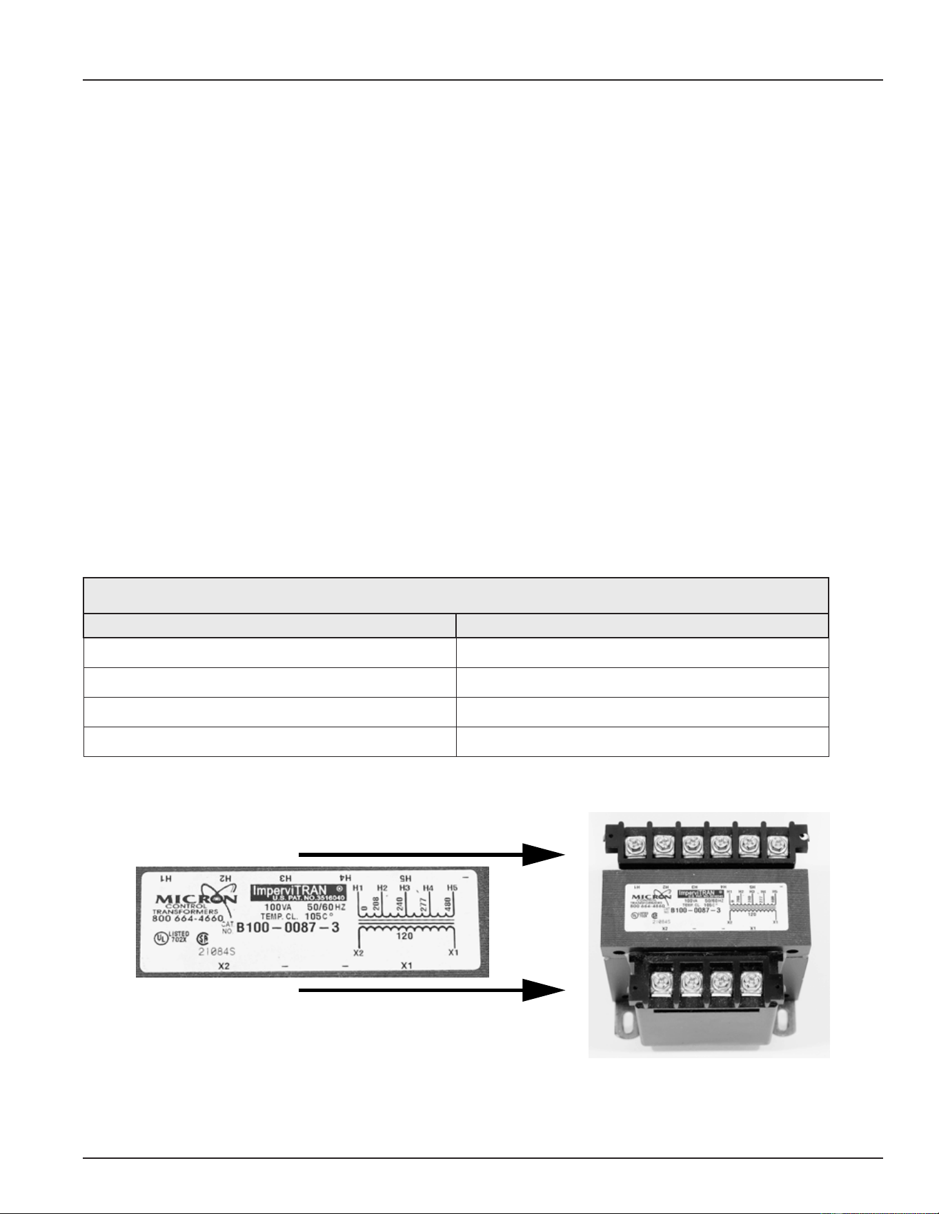
35
Servicing should only be performed by a Qualied Service Technician
TRANSFORMERS
This section of the manual provides information on how to test and ensure the multiple tap 120 VAC control-
circuit transformer and the 24 VAC transformer is wired properly on electronic control models. This section will
also provide test procedures for the 24 VAC transformer used by the electronic control system. See Figure 2
(page 10) for location of the transformers on these models. Surface-mount control models are not equipped
with transformers.
used by the electronic control system. See Figure 1 (page 9) and Figure 2 (page 10) for location of the
transformers.
120 VAC CONTROL CIRCUIT TRANSFORMER WIRING
The 120 VAC Control Circuit transformer is a multiple or “multi” tap transformer that can accept 4 different input
voltages to it’s primary winding. See Figure 2 (page 10) for location. This transformer outputs 120 VAC power
from it’s secondary winding which powers the CCB circuit board and the contactor coils. See Central Control
Board (CCB) (page 43). The input power wiring to the primary winding of this transformer must be congured to
match the power supplied to the water heater. Incorrect wiring can cause output voltage from the transformer’s
secondary winding to be too low or too high. This can cause “contactor chatter” (contacts open and close
rapidly) and may permanently damage the contactors and/or the CCB circuit board. The table and illustrations
that follow show how to properly congure the input power wiring to the transformers primary winding.
1. Only one wire needs to be moved on the transformer’s primary winding terminals to congure for a different
voltage. Do not move or change the wire connected to the H1 terminal on the primary winding. Do not move
or change either wire at the secondary winding X1 or X2 connections. Remove the wire from the terminal
marked H2 208, H3 240, H4 277 or H5 480 and attach it to the appropriate terminal that matches the water
heater’s power supply voltage.
Table 4. Voltage and Primary Winding Connections
Water Heater Power Supply Voltage Primary Winding Connections
208 VAC H1 Common & H2 (208)
240 VAC H1 Common & H3 (240)
277 VAC H1 Common & H4 (277)
480 VAC H1 Common & H5 (480)
Primary Winding
Secondary Winding
X1
X2
120 VAC
H1 H2 H3 H4 H5 N/A
Figure 32. Transformer Wiring (208/240/277 Volt Models)
Printed on 6/17/2020 12:05 PM CT
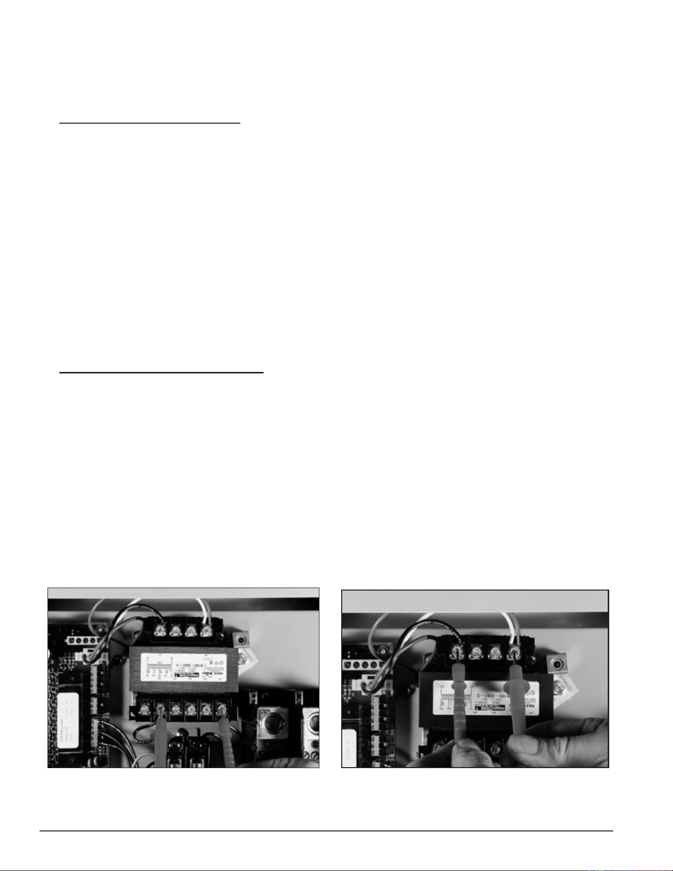
36
Servicing should only be performed by a Qualied Service Technician
120 VAC CONTROL CIRCUIT TRANSFORMER TEST
1. Ensure the main breaker or disconnect switch is turned on.
2. Verify with an AC volt meter that proper voltage is present at the power distribution block. See Figure 2 (page
10) and Single- and Three-Phase Power (page 13).
3. Check Primary Winding Voltage: Using an AC volt meter, set the volt meter to an AC voltage range above
the expected voltage (600 VAC or higher range initially). Touch the two volt meter probes between the control
circuit transformer’s primary winding H1 common terminal and the other primary winding terminal with a
power wired connected to it as shown in the “Primary Winding Voltage Test” image below. See Transformers
(page 35). Voltage between these two terminals should match the water heater’s power supply voltage. If
the voltage at the primary winding terminals of the transformer matches the water heater’s power supply
voltage the primary winding is being powered correctly. If the voltage measured is zero volts or considerably
less or more than the water heater’s power supply voltage:
• Check the wiring between the Control Circuit Transformer’s primary winding and the Control Circuit
Fuse Block. See Figure 2 (page 10) for location. Ensure wiring is correct and connections are tight
and making good contact.
• Check the wiring between the Control Circuit Fuse Block and the Power Distribution Block. Ensure wiring
is correct and connections are tight and making good contact.
• Check the control circuit fuses. See Figure 2 (page 10) for location and the Fuses test procedure (page
18).
• Verify 120 VAC control-circuit transformer wiring is correct. See Transformers (page 35).
4. Check Secondary Winding Voltage: Using an AC volt meter, set the volt meter to an AC voltage range
just above 120 VAC. Touch the two volt meter probes between the control-circuit transformer’s secondary
winding X1 and X2 terminals as shown in the “Secondary Winding Voltage Test” image below. There should
be approximately 120 VAC present between these two terminals. If the voltage measured is approximately
120 VAC, the control-circuit transformer is operating properly. If the voltage measured is zero volts or
considerably less or more (± 10%) than 120 VAC AND all steps above have been completed and the results
were successful, replace the control-circuit transformer. When replacing the control-circuit transformer,
check all wiring to and from the transformer for pinched or shorted wires. Repair or replace damaged wiring
as necessary.
Service Note: A continuity test can also be performed on the control-circuit transformer primary and
secondary windings to determine if either winding is an open circuit. Secure power to
the water heater. Disconnect all wiring to the transformer. Using an ohmmeter check for
continuity between the terminals on the primary and secondary windings checked in Steps 3
and 4 above.
Primary Winding Voltage Test
Secondary Winding Voltage Test
Figure 33. 120 VAC Control Circuit Winding Voltage Tests
Printed on 6/17/2020 12:05 PM CT
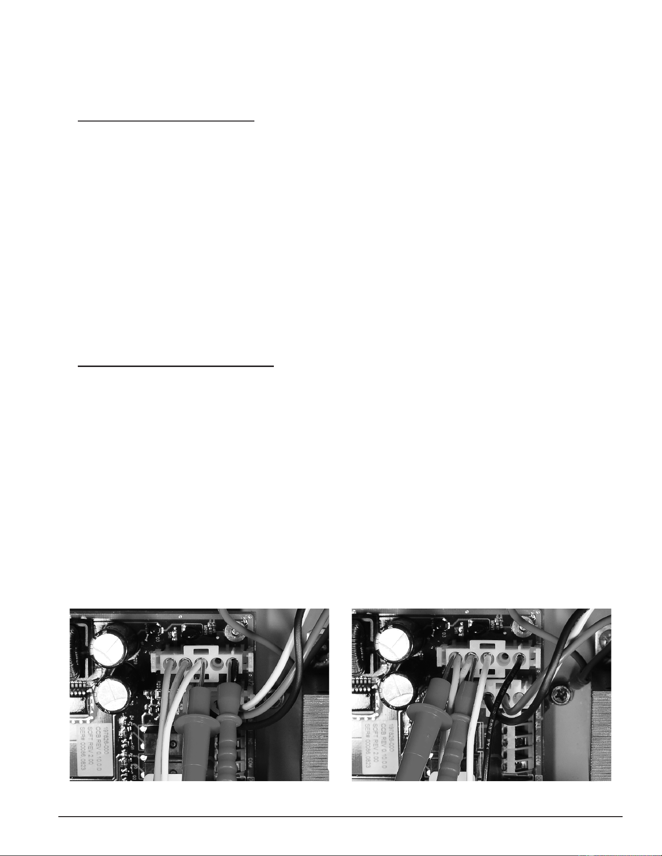
37
Servicing should only be performed by a Qualied Service Technician
24 VAC TRANSFORMER TEST
1. Ensure the main breaker or disconnect switch is turned on.
2. Verify with an AC volt meter that proper voltage is present at the power distribution block. See Figure 2 (page
10) for the location and Single- and Three-Phase Power (page 13)).
3. Check Primary Winding Voltage: Using an AC volt meter, set the volt meter to an AC voltage range just
above 120 VAC. With the J1 plug installed in the J1 socket on the Central Control Board (CCB) (page 43), insert
the two volt meter probes into pins 1 & 3 of the J1 plug as shown in the “Primary Winding Voltage Test”
image below. Volt meter probes may have to be pressed rmly into the plug to make contact with the metal
conductors inside. Voltage should be approximately 120 VAC. If the voltage measured is approximately 120
VAC the primary winding is being powered correctly. If the voltage measured is zero volts or considerably
less or more (± 10%) than 120 VAC:
• Check the J1 plug/socket connections on the CCB for wear or damage. Ensure they are mating properly
and providing good contact. See Central Control Board (CCB) (page 43).
• Check the 120 VAC control-circuit transformer to ensure it is wired correctly and outputting the correct
voltage. See 120 VAC Control Circuit Transformer Wiring (page 35) and 120 VAC Control Circuit Transformer Test
(page 36).
• Ensure there is 120 VAC being supplied to the CCB. See Checking Power and Ground to the CCB (page 47).
• Call the toll free technical support phone number on the back cover of this manual for further assistance
if all the procedures above have been performed and 120 VAC is still not present at pins 1 & 3 of the
J1 socket/plug on the CCB.
4. Check Secondary Winding Voltage: Using an AC volt meter, set the volt meter to an AC voltage range just
above 24 VAC. With the J1 plug installed in the J1 socket on the Central Control Board (CCB) (page 43), insert
the two volt meter probes into pins 4 & 5 of the J1 plug as shown in the “Secondary Winding Voltage Test”
image below. Volt meter probes may have to be pressed rmly into the plug to make contact with the metal
conductors inside. Voltage should be approximately 24 VAC. If the voltage measured is approximately 24
VAC, the transformer is operating properly. If the voltage measured is zero volts or considerably less or more
(± 5% expected) than 24 VAC:
• Check the J1 plug/socket connections on the CCB for wear or damage. Ensure they are mating properly
and providing good contact. See Central Control Board (CCB) (page 43).
• Check the wiring between pins 4 & 5 of the J1 plug and the 24 VAC transformer. See Figure 2 (page
10) for the location of the transformer. Ensure wiring is not pinched or shorted and continuous to the
24 VAC secondary winding. Repair or replace damaged wiring as necessary.
• If all the above procedures have been performed and there is still not 24 VAC present at pins 4 & 5 of
the J1 plug, replace the 24 VAC transformer. When replacing the transformer, check all wiring to and
from the transformer for pinched or shorted wires. Repair or replace damaged wiring as necessary.
Figure 34. 24 VAC Transformer Primary Winding Voltage Test Figure 35. 24 VAC Transformer Secondary Winding Voltage Test
Printed on 6/17/2020 12:05 PM CT
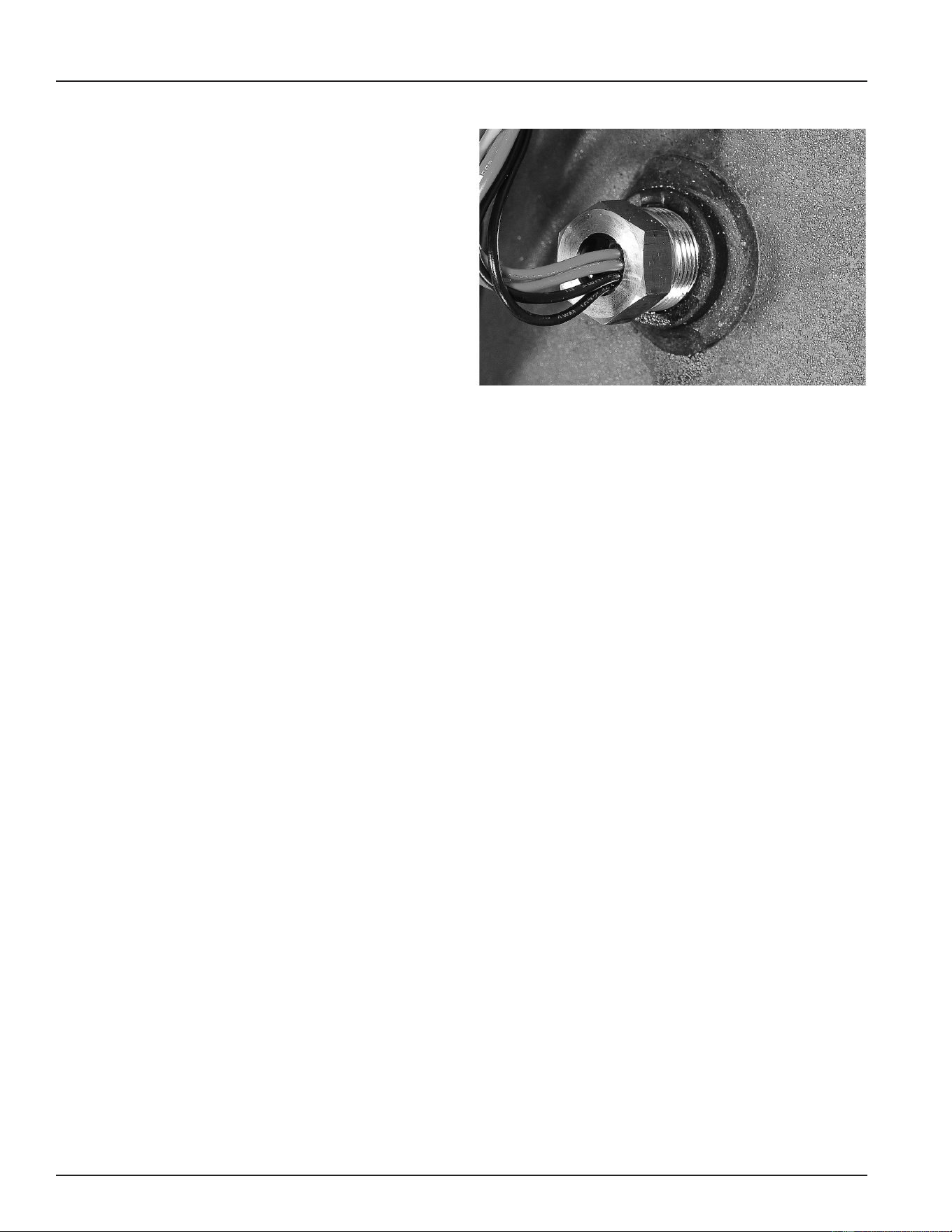
38
Servicing should only be performed by a Qualied Service Technician
IMMERSION TEMPERATURE PROBE
This section of the manual provides information on
how to test the immersion temperature probe. See
Figure 2 (page 10) for the location. The immersion
temperature probe contains the ECO (energy cut out)
and a Temperature Sensor. The immersion temperature
probe plugs into the CCB circuit board at the J5 socket.
See Central Control Board (CCB) (page 43) for location.
ECO HIGH TEMPERATURE LIMIT SWITCH
The ECO (energy cut out) is a high temperature limit
switch designed to protect against excessively high
water temperatures inside the water heater. The
ECO is a normally closed switch located inside the
immersion temperature probe (two red wires). The ECO
temperature setting is non adjustable. The contacts
open at 202°F/94°C and will close at approximately
140°F/60°C.
Figure 36. Immersion Temperature Probe
The control system constantly monitors the state of the ECO switch contacts. If the ECO activates (contacts
open) due to abnormally high water temperature the control system will lock out and display the fault message
“Energy Cut Out (ECO)” (Fault Condition) (page 71) on the UIM.
Voltage to the contactor coils and heating elements is terminated to prevent further heating operation. See
Contactor Coil Voltage Test - At Contactor (page 33) and Contactor Coil Voltage Test - At CCB (page 34).
Should the ECO activate, the water temperature must drop below 140°F/60°C before the control system can
be reset. Once the water temperature has cooled below this point, the power supply to the water heater must
be turned off and on again to reset the control system.
TEMPERATURE SENSOR
The temperature sensor located inside the immersion temperature probe is a “thermistor” (two black wires).
Thermistors are thermally sensitive resistors. As the water temperature rises the resistance (in ohms) of the
sensor will decrease; as the temperature falls the resistance will increase. See Table 5 (page 39). The control
system interprets the changes in resistance as changes in water temperature.
The control system constantly monitors the temperature sensor (thermistor) for temperature. The control
system is also programmed to declare a Fault condition if the resistance of the temperature sensor drops
below 390 ohms (shorted) or above 56,000 ohms (open).
If the resistance of the temperature sensor is below 390 ohms, the control system will lock out and display the
fault message “Temp Probe Short” (Fault Condition) (page 70) on the UIM. If the resistance of the temperature
sensor is above 56,000 ohms the control system will lock out and display the fault message “Temp Probe Open”
(Fault Condition) (page 70) displays on the UIM.
Voltage to the contactor coils and heating elements is terminated during lock out to prevent further heating
operation. See Contactor Coil Voltage Test - At Contactor (page 33) and Contactor Coil Voltage Test - At CCB (page 34).
If the control system locks out, the condition that caused the lock out must be corrected before the control
system can be reset by cycling power off and on again.
Printed on 6/17/2020 12:05 PM CT
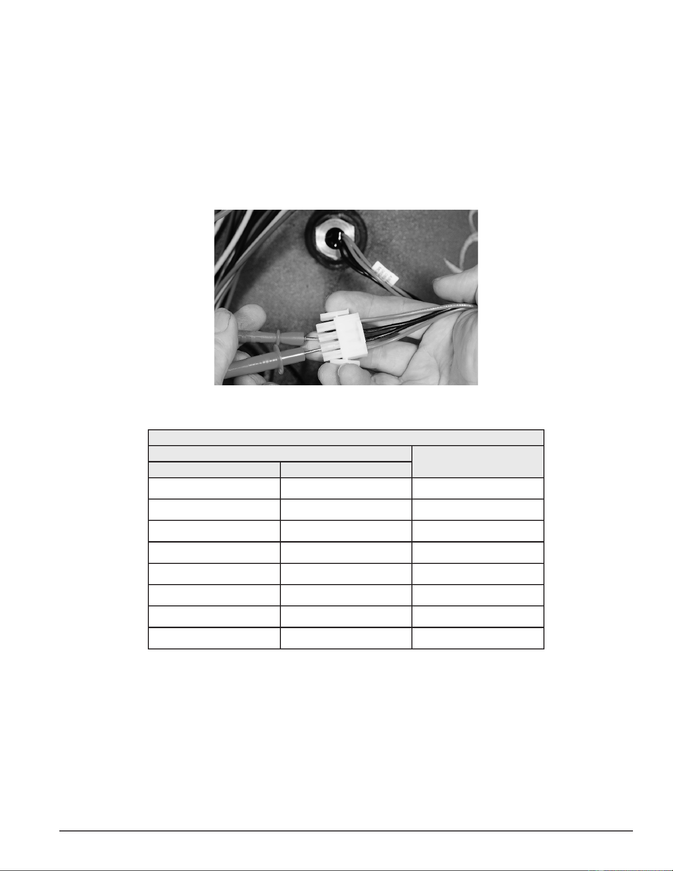
39
Servicing should only be performed by a Qualied Service Technician
TEMPERATURE SENSOR RESISTANCE TEST
1. Secure power to the water heater at the main breaker or disconnect switch.
2. Unplug the J5 plug from the CCB. See Central Control Board (CCB) (page 43)) for the location.
3. Using an ohmmeter: set the ohmmeter range to a scale above 30,000 ohms initially.
4. Touch the ohmmeter probes between the two middle pins (black wires) of the J5 plug end as shown in the
image below. Compare the measured resistance value (ohms) to the values given in the resistance data
table below. Temperature probes are very reliable and should only be replaced when:
• The resistance test indicates an “open” (innite resistance) or a “direct short” (no resistance) circuit.
• The nature of the service problem is temperature control and the resistance readings are considerably
(± 25%) different than the values in the table here at the given temperature.
Figure 37. Checking Temperature Sensor Resistance
Table 5. Temperature Sensor Resistance Data
WATER TEMPERATURE
RESISTANCE IN OHMSCelsius Fahrenheit
3° 40° 26,435
21° 70° 11,974
38° 100° 5,862
49° 120° 3,780
55° 130° 3,066
60° 140° 2,503
71° 160° 1,698
82° 180° 1,177
Printed on 6/17/2020 12:05 PM CT
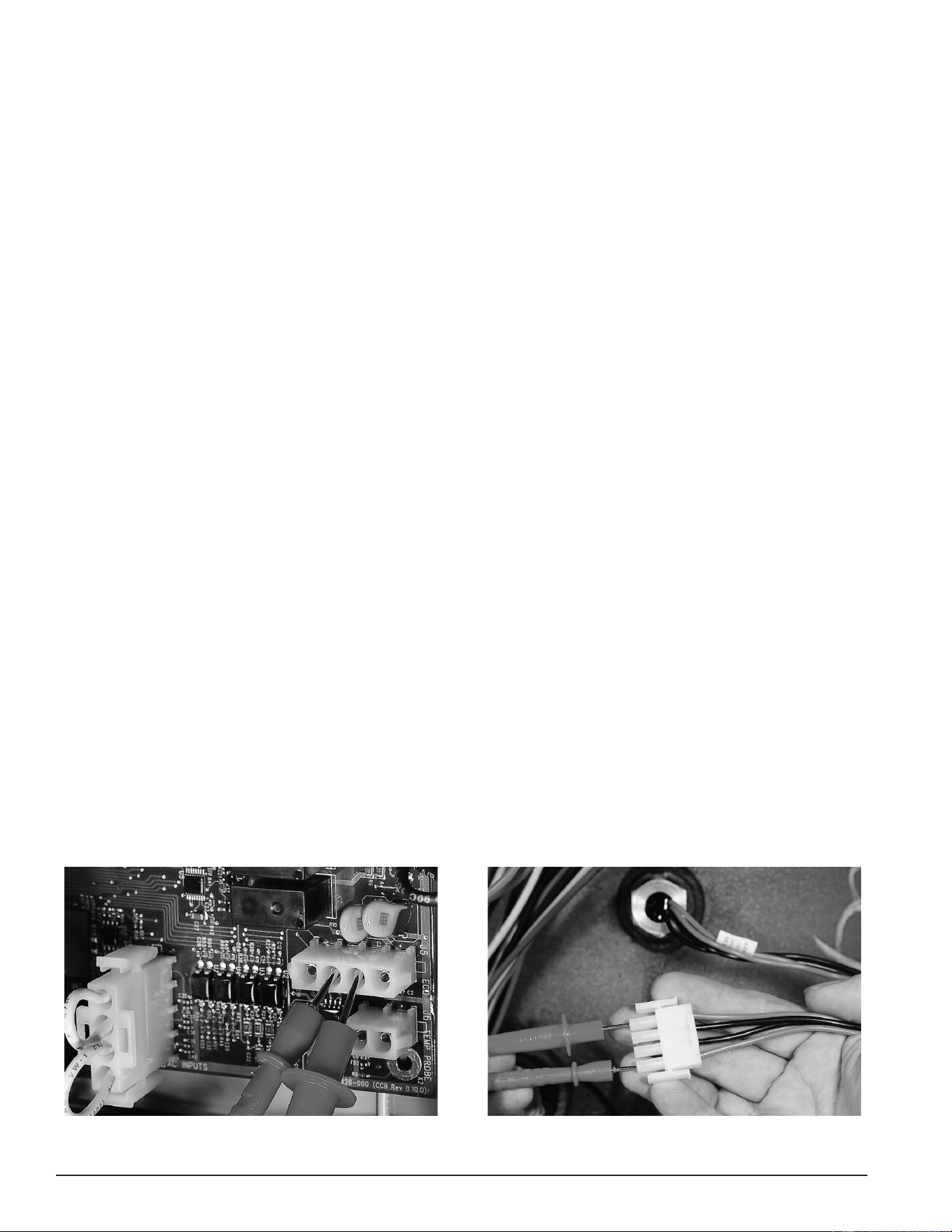
40
Servicing should only be performed by a Qualied Service Technician
TEMPERATURE SENSOR DC VOLTAGE TEST
1. Ensure the main breaker or disconnect switch is turned on.
2. Verify the CCB circuit board has the correct input voltage at the J2 socket and is properly grounded. Perform
the Checking Power and Ground to the CCB (page 47).
3. Unplug the J5 plug from the CCB (note: the control system will lock out and display “Temp Probe Open”
Fault message on the UIM when the J5 plug is removed. Cycle power off and reinstall J5 plug when tests
are complete). Using a “DC” (direct current) volt meter, check for DC voltage between pins 2 & 3 of the J5
socket as shown in the “DC Voltage To Temperature Sensor” image below.
• If the measured voltage is 5 VDC, the sensor is being powered correctly. If there is not 5 VDC, call the
toll free Technical Support phone number listed on the back cover of this manual for further assistance.
ECO CONTINUITY TEST
1. Secure power to the water heater at the main breaker or disconnect switch.
2. Unplug the J5 plug from the CCB. See Central Control Board (CCB) (page 43) for location.
3. Ensure tank temperature is less than 100°F/38°C. Dump water to lower tank temperature if necessary.
4. Using an ohmmeter, set the ohmmeter to it’s lowest resistance range (< 200) or to an audible beep continuity
test setting if so equipped.
5. Touch the ohmmeter probes between the two outside pins (red wires) of the J5 plug end as shown in the
“Checking ECO Switch Continuity” image below.
• If the ohmmeter shows continuity (closed circuit) between the two outside pins (red wires) of the J5 plug
end the ECO switch has reset properly. If the control system continues to lock out displaying the “Energy
Cut Out (ECO)” Fault message with continuity through the ECO present call the toll free Technical Support
phone number listed on the back cover of this manual for further assistance.
• If the ohmmeter shows no continuity (open circuit) between the two outside pins (red wires) of the
J5 plug end and the tank temperature is known to be at or below 100°F/38°C, replace the immersion
temperature probe. Secure power to the water heater and drain the water heater before replacing the
probe. Follow the draining and lling instructions in the maintenance section of the instruction manual
that came with the water heater.
• If the control system continues to lock out, displaying the fault message “Energy Cut Out (ECO)” and
the water temperature inside the water heater is becoming excessive (at or above 202°F/94°C), check
contactors (Contactors (page 30)) to ensure they are not stuck closed. Check for voltage at all heating
elements during standby mode. See Heating Element Voltage Test (page 25). Check water system piping.
Ensure heat is not being added by any other heating appliances or heat sources. If all these tests have
been performed and the control system continues to lock out, displaying the “Energy Cut Out (ECO)”
fault message, call the toll free Technical Support phone number listed on the back cover of this manual
for further assistance.
Figure 38. DC Voltage To Temperature Sensor
Figure 39. Checking ECO Switch Continuity
Printed on 6/17/2020 12:05 PM CT
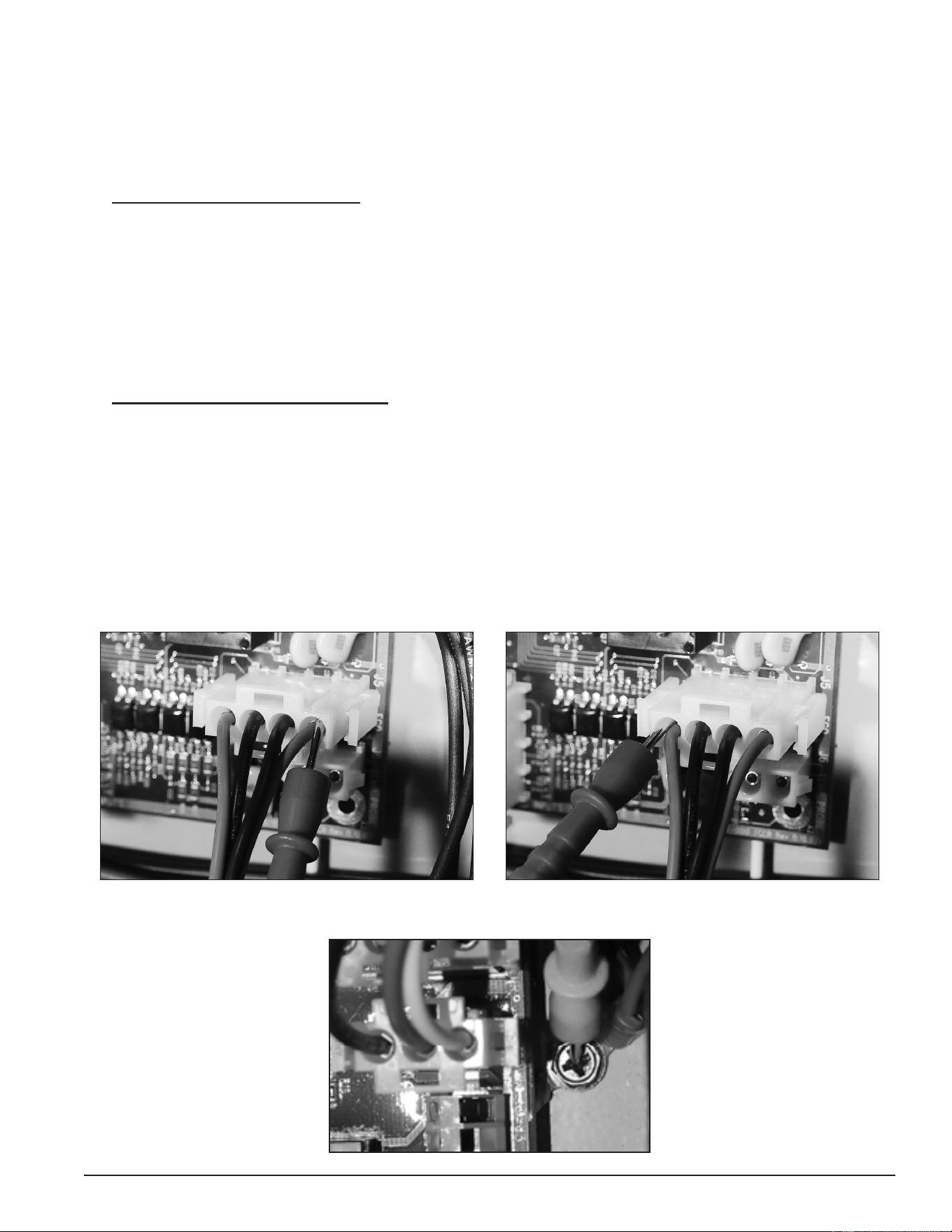
41
Servicing should only be performed by a Qualied Service Technician
ECO VOLTAGE TEST
1. Ensure the main breaker or disconnect switch is turned on.
2. Verify the CCB has the correct input voltage at the J2 socket and is properly grounded. Perform the Checking
Power and Ground to the CCB test (page 47).
3. Using an AC volt meter; set the volt meter to an AC voltage range just above 120 VAC.
4. Check for 120 VAC to the ECO: With the J5 plug installed in the J5 socket on the Central Control Board (CCB)
(page 43), insert one of the two volt meter probes into pin 1 of J5 plug as shown in the “120 VAC To ECO”
image below. Volt meter probe may have to be pressed rmly into the plug to make contact with the metal
conductor inside. Touch the other volt meter probe to the ground wire connection on the water heater as
shown in the "Ground Connection" image below. The measured voltage should be approximately 120 VAC.
• If the measured voltage is approximately 120 VAC proceed to Step 5.
• If the measured voltage is zero or considerably less or more than 120 VAC and all steps above have
been performed, call the toll free Technical Support phone number listed on the back cover of this manual
for further assistance.
5. Check for 120 VAC from the ECO: With the J5 plug installed in the J5 socket on the Central Control Board
(CCB) (page 43), insert one of the two volt meter probes into pin 4 of J5 plug as shown in the “120 VAC From
ECO” image below. Volt meter probe may have to be pressed rmly into the plug to make contact with the
metal conductor inside. Touch the other volt meter probe to the ground wire connection on the water heater.
The measured voltage should be approximately 120 VAC.
• If the measured voltage is approximately 120 VAC, the ECO switch is closed and the control system
should not be declaring an ECO Fault condition. If the control system continues to lock out, displaying
the “Energy Cut Out (ECO)” Fault message in this condition, call the toll free Technical Support phone
number listed on the back cover of this manual for further assistance.
• If the measured voltage is zero volts or considerably less than 120 VAC, perform the ECO Continuity Test
(page 40).
Figure 40. 120 VAC To ECO
Figure 41. 120 VAC From ECO
Figure 42. Ground Connection
Printed on 6/17/2020 12:05 PM CT
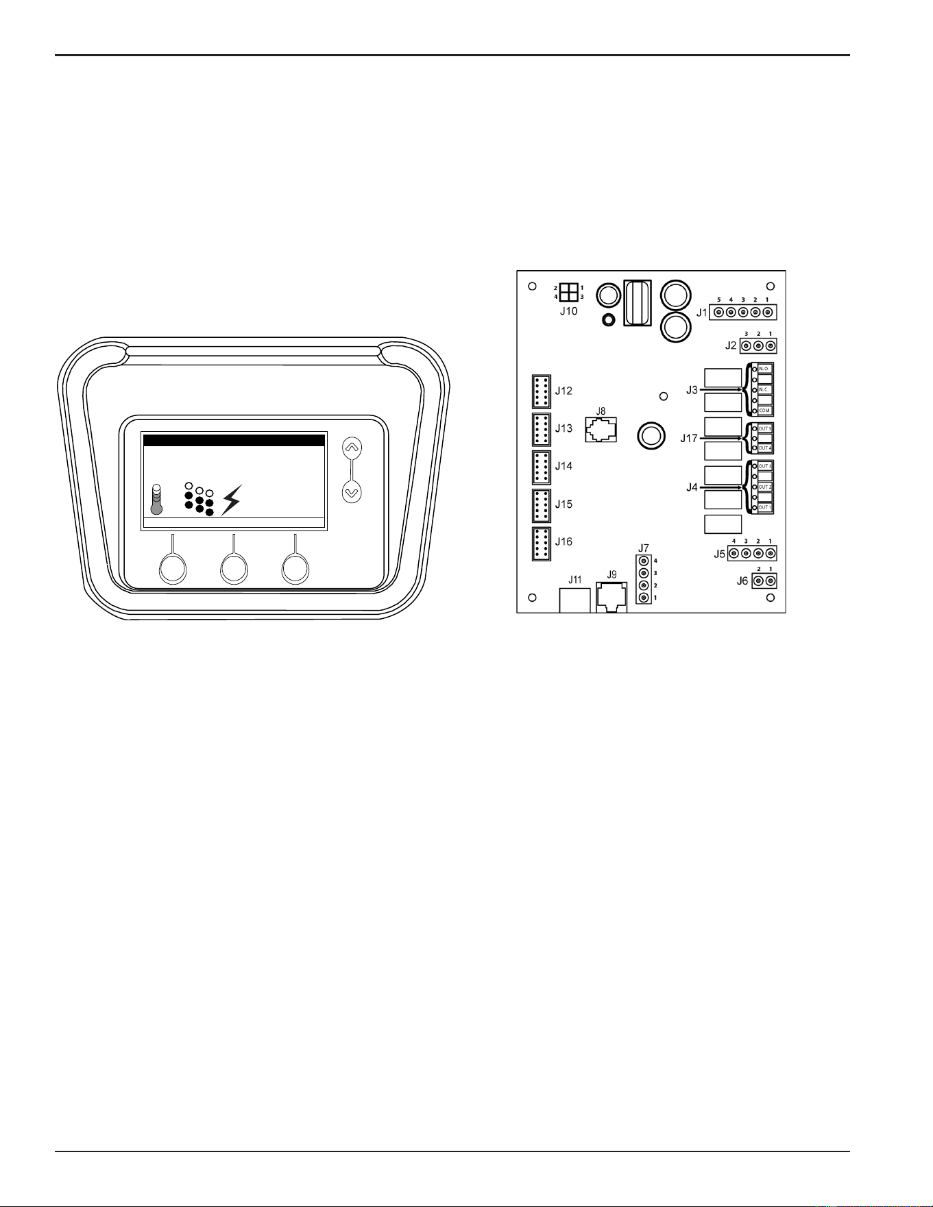
42
Servicing should only be performed by a Qualied Service Technician
ELECTRONIC CONTROLS
This section covers the electronic control system used on Electronic Control Models. See Figure 1 (page 9).
The control system includes a CCB (Central Control Board) and a UIM (User Interface Module).
The CCB constantly monitors safely controls, heating elements, water temperature and other functions of the
water heater. Operational information is continuously reported to the user through text and icons on the liquid
crystal display (LCD) portion of the UIM. When there are operational problems Fault and Alert messages will
also be displayed. Users can navigate through multiple control system menus to view operational information
and change user settings. See the Electronic Control System (page 49).
Tank Temperature 114°F
Operating Setpoint 120°F
Status: Standby
HELP
MODEL INFORMATION
MENU
Friday
5:00 PM
Normal Mode
Figure 43. UIM (User Interface Module) Figure 44. CCB (Central Control Board)
Printed on 6/17/2020 12:05 PM CT
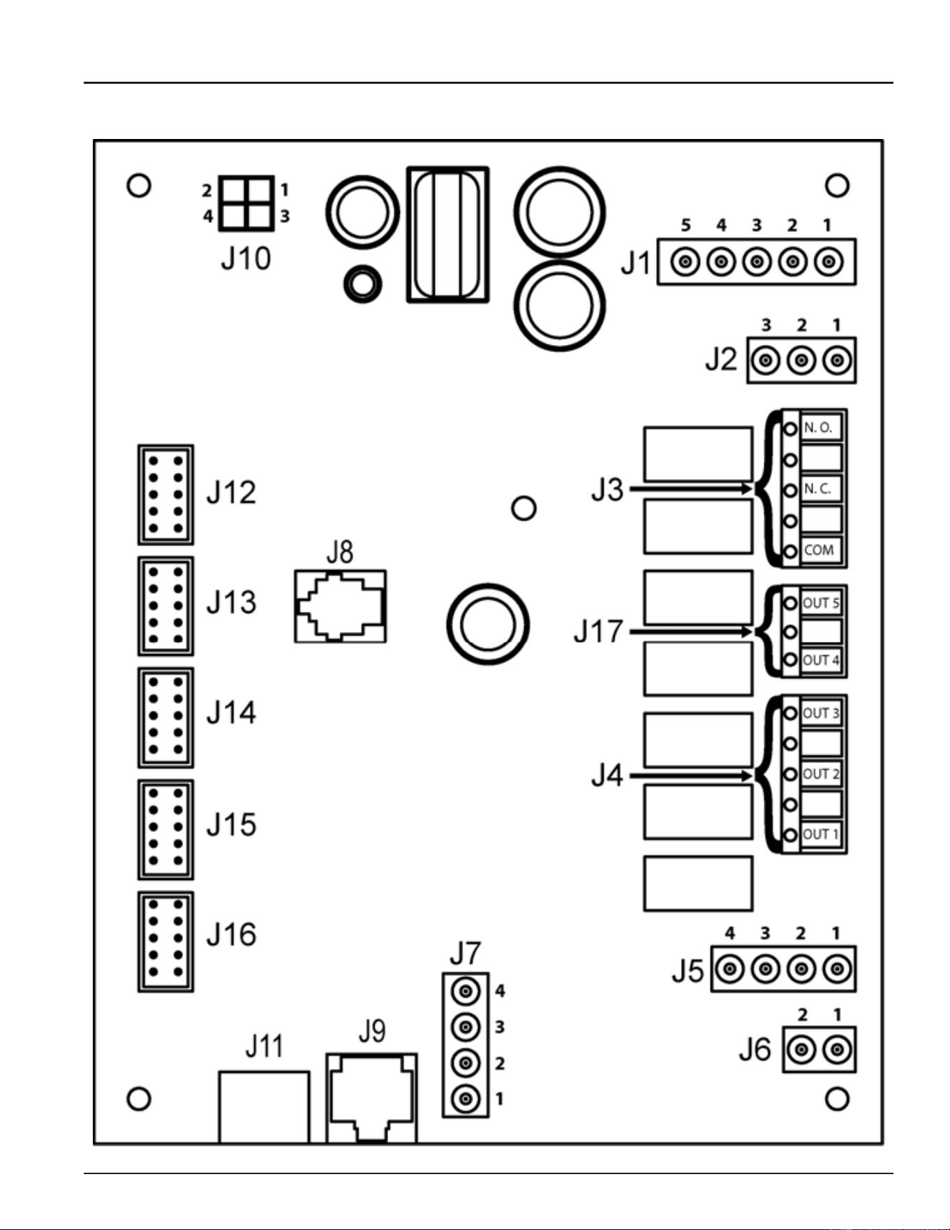
43
Servicing should only be performed by a Qualied Service Technician
CENTRAL CONTROL BOARD (CCB)
All wiring connections and sockets will be identied in the following pages. The Troubleshooting section of
this manual will refer to this illustration and information.
Printed on 6/17/2020 12:05 PM CT
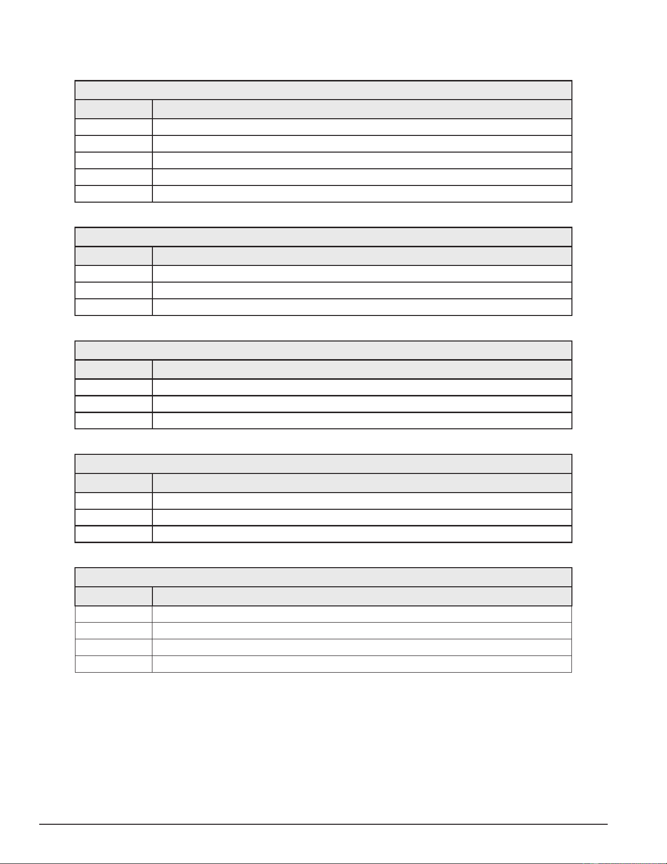
44
Servicing should only be performed by a Qualied Service Technician
CCB SOCKET & WIRING TERMINAL IDENTIFICATION
Refer to the illustration (page 43) for physical location of the sockets and wiring terminals.
Table 6. J1 Socket - Transformer
Pin # Description
1
120 VAC hot to transformer
2
Not used
3
120 VAC neutral to transformer
4
24 VAC out from transformer
5
24 VAC out from transformer
Table 7. J2 Socket - 120 VAC Power Supply
Pin # Description
1
120 VAC hot
2
Earth Ground
3
120 VAC neutral
Table 8. J3 Wiring Terminals - Alarm Output Relay (see page 68)
Terminal Description
N. O.
Dry Contact Output - Normally Open Terminal Alarm Output Relay
N. C.
Dry Contact Output - Normally Closed Terminal Alarm Output Relay
COM
Dry Contact Output - Common Terminal Alarm Output Relay
Table 9. J4 Wiring Terminals - Contactor Coils
Terminal Description
OUT 1
120 VAC hot to Heating Element #1 Contactor Coil
OUT 2
120 VAC hot to Heating Element #2 Contactor Coil - if so equipped
OUT 3
120 VAC hot to Heating Element #3 Contactor Coil - if so equipped
Table 10. J5 Socket - Immersion Temperature Probe/ECO
Pin # Description
1
ECO (energy cut out) 120 VAC hot out (red wire)
2
Temperature probe (thermistor) +5.0 VDC (black wire)
3
Temperature probe (thermistor) -5.0 VDC (black wire)
4
ECO (energy cut out) 120 VAC return (red wire)
J6 Socket - Not Used
Printed on 6/17/2020 12:05 PM CT

45
Servicing should only be performed by a Qualied Service Technician
Table 11. J7 Socket - Enable / Disable Circuits 1 & 2 (see pages 53 & 63)
Pin # Description
1
Enable/Disable circuit 1
2
Enable/Disable circuit 1
3
Enable/Disable circuit 2
4
Enable/Disable circuit 2
J8 Socket - Not Used
J9 Socket - Not Used
J10 Socket - Not Used
J11 Port - Communication Port - UIM Display (user interface module)
J12 Socket - Heating Element #1 Sensors
J13 Socket - Heating Element #2 Sensors
J14 Socket - Heating Element #3 Sensors
J15 Socket - Heating Element #4 Sensors
J16 Socket - Heating Element #5 Sensors
J17 Wiring Terminals - Not Used
Printed on 6/17/2020 12:05 PM CT
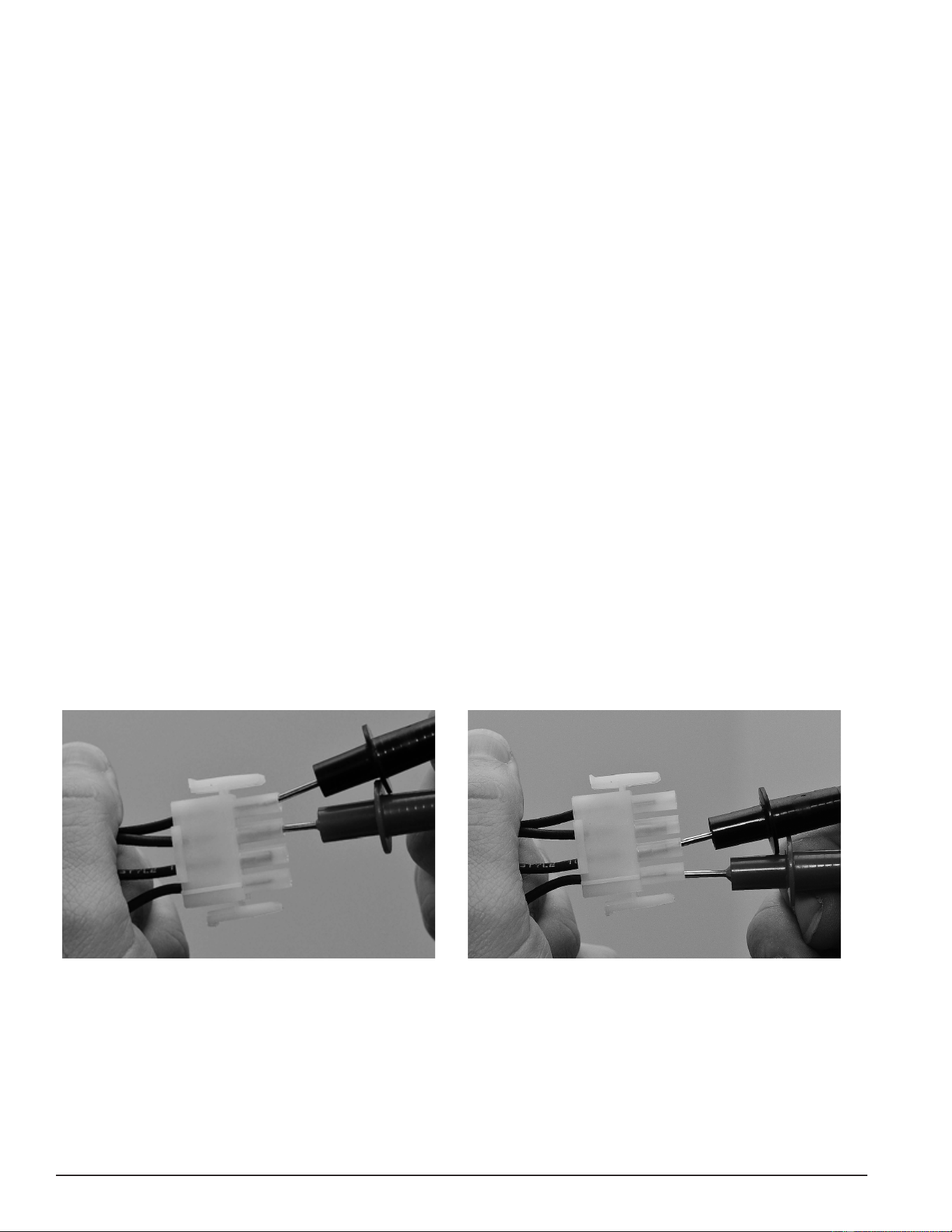
46
Servicing should only be performed by a Qualied Service Technician
CCB ENABLE/DISABLE CIRCUIT(S) TEST
The electronic control system includes two enable/disable circuits (page 55) for use with eld installed
supervisory controls such as building EMS (Energy Management System). These two circuits are located at
the CCB’s four pin J7 Socket. Both of these enable/disable circuits must be closed to enable heating operation.
If either circuit is open for any reason, heating operation will be disabled, even though the tank temperature
may be well below the Operating Set Point. See Heating Cycle Disabled (page 68).
There is a plug with two jumper wires installed from the factory in the CCB J7 socket to enable heating operation
when external controls are not in use. If the plug is not present, or if one of the two jumper wires fails to close,
either enable/disable circuit heating operation will be disabled. A simple continuity check is performed on the
J7 Plug end to ensure heating should not be disabled as follows:
1. If either enable/disable circuit is in use (external wiring connected to J7 plug) by an external supervisory control,
ensure that control’s dry contacts are closed to enable heating operation. Check the supervisory control’s
settings/programming to ensure it is not disabling heating operation during occupied/peak demand periods.
2. If the J7 plug is missing or jumper wires are not installed in the J7 plug, call the toll free Technical Support
phone number listed on the back cover of this manual for further assistance.
3. If there are no external supervisory controls wired to the J7 plug, secure power to the water heater. Unplug
the J7 plug from the CCB. See Central Control Board (CCB) (page 43) for location.
4. Using an ohmmeter, set the ohmmeter to it’s lowest resistance range (< 200), or to an audible beep continuity
test setting if so equipped.
5. Touch the ohmmeter probes between pins 1 & 2 rst and then between pins 3 & 4 of the J7 plug end as
shown in the images below. There should be continuity present in both tests.
• If the ohmmeter shows no continuity (open circuit) between pins 1 & 2 or between pins 3 & 4 of the J7
plug end, ensure that the two jumper wires are properly installed in the plug end and are not broken.
Ensure the J7 plug/socket connection is mating properly and providing good contact. Repair/replace
damaged plug connectors/wiring as necessary.
• If the ohm meter shows continuity (closed circuit) between pins 1 & 2 and between pins 3 & 4 of the
J7 plug end and heating operation will not activate with a cold tank of water call the toll free Technical
Support phone number listed on the back cover of this manual for further assistance.
Figure 45. Testing for Continuity Between Pins 1 & 2 Figure 46. Testing for Continuity Between Pins 3 & 4
Service Note: If a supervisory control(s) is used to enable/disable heating operation, install eld wiring
between the J7 socket on the CCB and a set of “dry contacts” on the external control per
all applicable building codes. This is a switching circuit only; DO NOT apply any external
voltage or connect any load (IE: relay coil) to either circuit.
Printed on 6/17/2020 12:05 PM CT
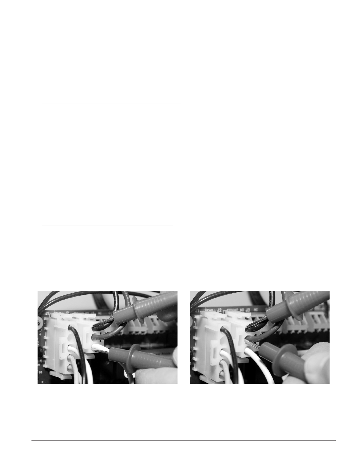
47
Servicing should only be performed by a Qualied Service Technician
CHECKING POWER AND GROUND TO THE CCB
The CCB is powered by the 120 VAC control-circuit transformer (page 36) at the J2 Socket, pins 1 & 3.
See Central Control Board (CCB) (page 43)). This procedure is performed to ensure that the 120 VAC power is
being supplied to the CCB.
1. Ensure the main breaker or disconnect switch is turned on.
2. Verify with an AC volt meter that proper voltage is present at the power distribution block. See Figure 2 (page
10).
3. Using an AC volt meter, set the volt meter to an AC voltage range just above 120 VAC.
4. Ensure 120 VAC power is supplied to the CCB. With the J2 plug installed in the J2 socket on the Central
Control Board (CCB) (page 43), insert the two volt meter probes into pins 1 & 3 of the J2 plug as shown in the
“Checking for 120 VAC” image below. Volt meter probes may have to be pressed rmly into the plug to make
contact with the metal conductors inside. Voltage should be approximately 120 VAC.
5. If the measured voltage is approximately 120 VAC, the CCB is receiving the correct power.
6. If the measured voltage is zero volts or considerably less than 120 VAC, do the following:
• Check the 120 VAC wiring between the CCB J2 socket and the 120 VAC control-circuit transformer.
Ensure wiring is correct and connections are tight and making good contact.
• Check the J2 plug/socket connections on the CCB for wear or damage. Ensure they are mating properly
and providing good contact. See Central Control Board (CCB) (page 43).
• Check the 120 VAC control-circuit transformer to ensure it is wired correctly and outputting the correct
voltage. See Transformers (page 35).
• Check the Control Circuit fuses. See Figure 2 (page 10) for location and the Fuses test procedure (page
18).
7. Ensure earth ground is supplied to the CCB. With the J2 plug installed in the J2 socket on the CCB (page
43), insert the two volt meter probes into pins 1 & 2 of the J2 plug as shown in the “Checking for Ground”
image below. Volt meter probes may have to be pressed rmly into the plug to make contact with the metal
conductors inside. If the measured voltage is approximately 120 VAC, the CCB is properly grounded.
8. If the measured voltage is zero volts or considerably less than 120 VAC:
• Check the ground wiring between the CCB J2 socket and the water heater’s ground connection. Ensure
wiring is correct and connections are tight and making good contact.
• Ensure the water heater is properly grounded.
Figure 47. Checking for 120 VAC Power Figure 48. Checking for Ground
Printed on 6/17/2020 12:05 PM CT
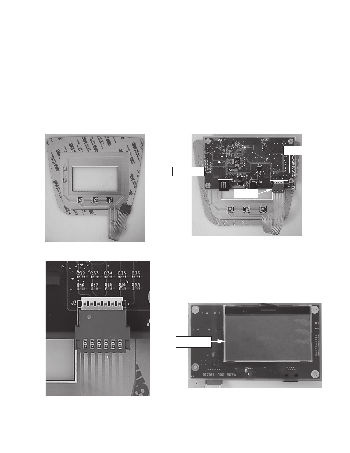
48
Servicing should only be performed by a Qualied Service Technician
User Interface Module (UIM)
UIM Components
The UIM’s major components include a Circuit Board with LCD display and a Button Pad Overlay which
contains the ve user input buttons.
Service Note: The Ribbon Cable that connects the Button Pad Overlay to the UIM Circuit Board must be
plugged in exactly as shown in the images below; with the metal crimp connections visible
on the plug end and the UIM Circuit Board back facing out. There are six pins on this Ribbon
cable socket, Ensure all six pins are inserted into the Ribbon Cable plug whenever removing
or installing the UIM or Button Pad Overlay.
Failure to connect this Ribbon cable exactly as shown when servicing will render the User Input Buttons
inoperable. This should be checked whenever the nature of the service complaint is an inoperable or
unresponsive controller or UIM.
Figure 49. Button Pad Overlay
J2 Socket -
CCB Communication
J3 Socket - Button
Pad Communication
Ribbon Cable to
Button Pad
Figure 50. UIM Circuit Board Back
Figure 51. Ensure that the ribbon cable is installed exactly as shown.
LCD Screen
Figure 52. UIM Circuit Board Front
Printed on 6/17/2020 12:05 PM CT
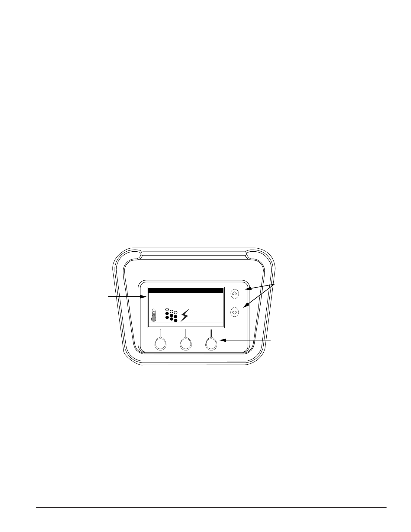
49
Servicing should only be performed by a Qualied Service Technician
ELECTRONIC CONTROL SYSTEM
CONTROL SYSTEM FEATURES
Advanced Diagnostics
Plain English text and animated icons display detailed operational and diagnostic information. LCD screen
on the front of the water heater displays the Sequence of Operation in real time. Fault or Alert messages are
displayed when operational problems occur. An Advanced Service menu displays a list of possible causes for
current fault and alert conditions to aid in servicing. See Troubleshooting (page 66).
Economy Mode Operation
The control system automatically lowers the Operating Set Point by a programmed value during user dened
time periods. This helps reduce operating costs during unoccupied or peak demand periods. See Economy
Mode Setup Menu (page 56) .
Linear Sequencing
First bank on is the last bank off. Banks of heating elements (3 elements per bank) are energized according
to adjustable (1 to 20°) differential set points for each bank. See Temperatures Menu (page 53). Helps reduce
operating costs during low/moderate loads.
CONTROL SYSTEM NAVIGATION
The User Interface Module (UIM) is located on the front cabinet of the the Electronic Control Model water
heaters. All operational information and user settings are displayed and accessed using the UIM. The UIM
includes ve snap acting (momentary) user input buttons: Up and Down buttons and 3 Operational Buttons.
Tank Temperature 114°F
Operating Setpoint 120°F
Status: Standby
HELP
MODEL INFORMATION
MENU
Friday
5:00 PM
Normal Mode
LCD Screen
Information
Display Area
Up & Dow Buttons
Navigate Menu Items
Adjust User Settings
3 Operational Buttons
Navigate Menus
Activate Adjustment Modes
Update/Cancel Changes
Figure 53. User Interface Module (UIM) Screen Components
Up & Down Buttons
Used to navigate (up and down) and to select (highlight) menu items. Also used to adjust or change (increase/
decrease, on/off, set time) various user settings.
Operational Buttons
The three Operational Buttons are multifunctional. Their current function is dened by the text that appears
directly above each button on the LCD screen. The function will change depending on what menu is currently
displayed or what menu item is selected. When no text appears on the LCD screen above an Operational
Button there is no function assigned.
Printed on 6/17/2020 12:05 PM CT
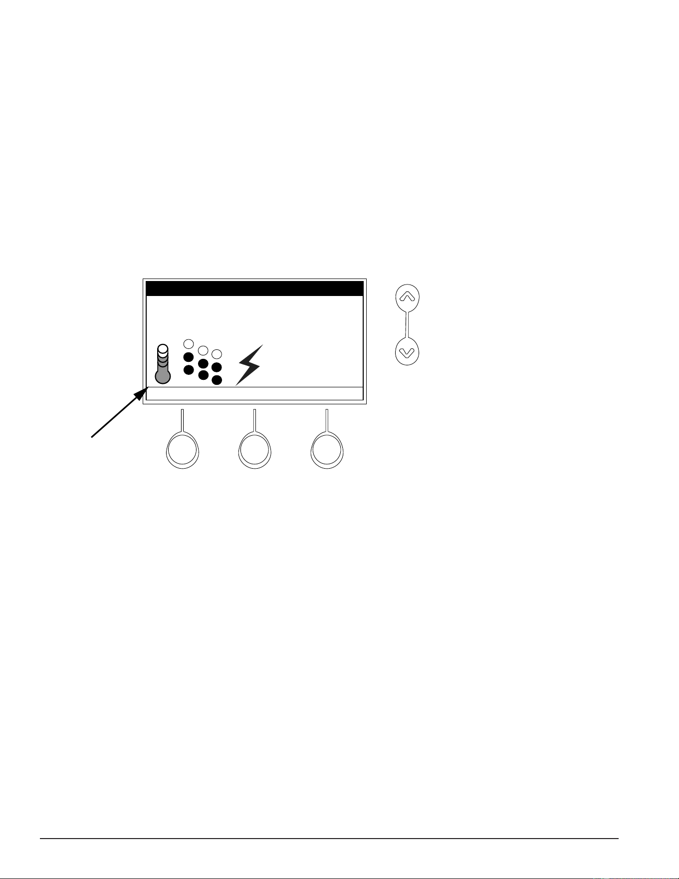
50
Servicing should only be performed by a Qualied Service Technician
THE DESKTOP SCREEN
The illustration below shows the control system “Desktop Screen.” This is the default screen. If there are no
active Fault or Alert conditions and no user input for approximately 10 minutes the control system will return
to this screen automatically.
Model Information: Model information and menu titles are shown in the black bar at the top of the Desktop
Screen.
Tank Temperature: Current water temperature as sensed from the Immersion Temperature Probe (page 38).
Operating Set Point: Temperature at which the control system will maintain tank (water) temperature in the
Normal Mode. This line of text will read Economy Set Point whenever the control system is operating in the
Economy Mode. See Temperatures Menu (page 53) and Economy Mode Setup Menu (page 56).
Status: The Operating State of the control system is displayed beneath the Operating Set Point. See Table
13 (page 52).
Status Icons
Tank Temperature 114°F
Operating Setpoint 120°F
Status: Standby
HELP
MODEL INFORMATION
MENU
Friday
5:00 PM
Normal Mode
Figure 54. Status Icons on the Model Information Screen
Service Note: The Desktop
Screen displays
text and animated
icons that convey
operational
information.
Review the Status Icons
explanation in Table 12, Status Icons
(page 51). Learning to use this real
time visual display of the operating
sequence will help to quickly and
accurately diagnose operational
problems.
Day/Time/Operating Mode: The current time and day are also displayed on the Desktop Screen. “Clock Not
Set” will be displayed until the time clock has been initially set. Day and Time are adjusted in the Economy
Mode settings. See Economy Mode Setup Menu (page 56). The current Operating Mode, either Normal Mode or
Economy Mode, is displayed beneath the day and time.
Menu: The left Operational Button is pressed to enter the Main Menu where all control system menus are
accessed. See Table 14 (page 52) for a list of control system menus.
Help: The right Operational Button is pressed to access instructions and explanations for user settings,
Operating States, Status Icons, manufacturer’s web address, the technical support phone number, and service
agent contact information.
Discreet Menu Contact Information: From the Desktop Screen, press and hold down the middle (unmarked)
Operational Button for 30 seconds and then release it. This will launch a discreet menu where personalized
contact information can be entered. Installing contractors and/or service agents can enter their company
name and telephone number. This contact information will be displayed with all Fault and Alert messages.
Printed on 6/17/2020 12:05 PM CT
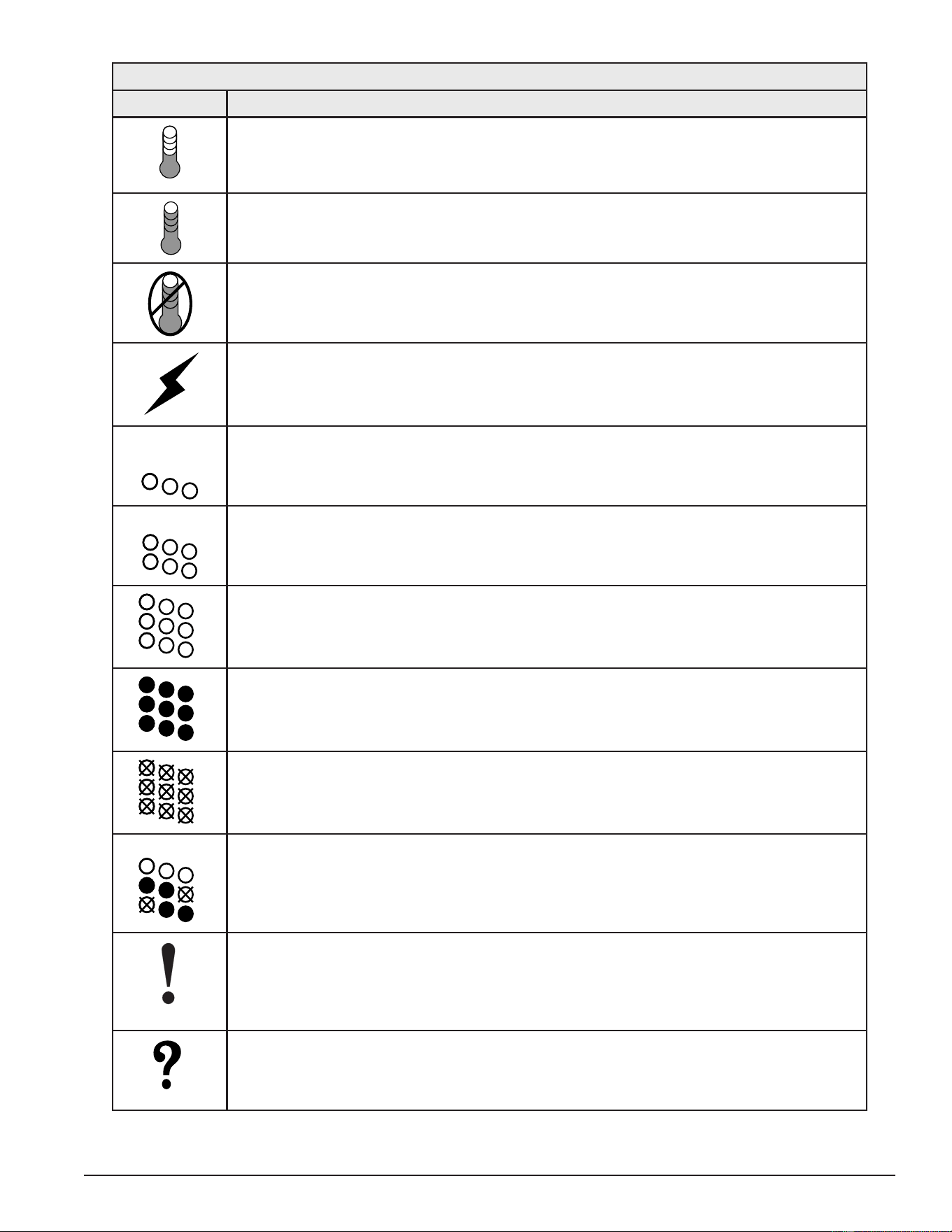
51
Servicing should only be performed by a Qualied Service Technician
Table 12. Status Icons
Icon Description
Water temperature in the tank has fallen. Shaded area of the animated thermometer icon
will rise and fall in response to water temperature in the storage tank as sensed from the
immersion Temperature Probe.
Water temperature in the tank has reached the Operating Set Point. Shaded area of the
animated thermometer icon will rise and fall in response to water temperature in the stor-
age tank as sensed from the immersion Temperature Probe.
The control is unable to initiate a heating cycle. This will happen whenever a Fault condi-
tion is detected by the control system or when either of the two Enable/Disable circuits are
open circuits. For more information on Enable/Disable circuits review Heater Status Menu (page
55).
The control system is in Heating Mode and has energized the electromagnetic contactor
coils for at least one heating element. This animated icon DOES NOT indicate current has
been sensed from the heating elements, only that there is a call for heat present and the
control system has initiated heating element operation.
Heating elements icon for a water heater equipped with 1 Bank of heating elements. Each
circle represents one heating element. Each diagonal row of 3 elements = 1 Bank of ele-
ments. Open circles represent heating elements the control system has not energized and
is not sensing electrical current from.
Heating elements icon for a water heater equipped with 2 Banks of heating elements. Each
circle represents one heating element. Each diagonal row of 3 elements = 1 Bank of ele-
ments. Open circles represent heating elements the control system has not energized and
is not sensing electrical current from.
Heating elements icon for a water heater equipped with 3 Banks of heating elements. Each
circle represents one heating element. Each diagonal row of 3 elements = 1 Bank of ele-
ments. Filled circles represent heating elements the control system has energized AND is
sensing electrical current from.
Heating elements icon for a water heater equipped with 3 Banks of heating elements. Each
circle represents one heating element. Each diagonal row of 3 elements = 1 Bank of ele-
ments. Open circles with an X represent heating elements the control system has ener-
gized that it IS NOT sensing electrical current from.
Heating elements icon for a water heater equipped with 3 Banks of heating elements. In
this example 2 Banks (6 elements) have been energized and 3 elements have not. The
control system is sensing electrical current from 4 heating elements. The control system is
reporting that it is not sensing electrical current from 2 elements that it should be sensing
current from. The control system would declare an Alert Condition in this case.
The control has detected/declared a Fault Condition. Fault message details can be viewed
in the Current Fault menu. Heating operation is discontinued (locked out) until the condition
that caused the Fault is corrected. Power to the water heater must be cycled off and on to
reset the control system. Note; cycling power will not reset the control system if the condi-
tion that caused the Fault has not been corrected.
The control has detected/declared an Alert Condition. The water heater will continue to
operate during an Alert Condition but there is an operational condition that requires the
attention of a Qualied Service Agent. Alert message details can be viewed in the Current
Alert menu.
Printed on 6/17/2020 12:05 PM CT
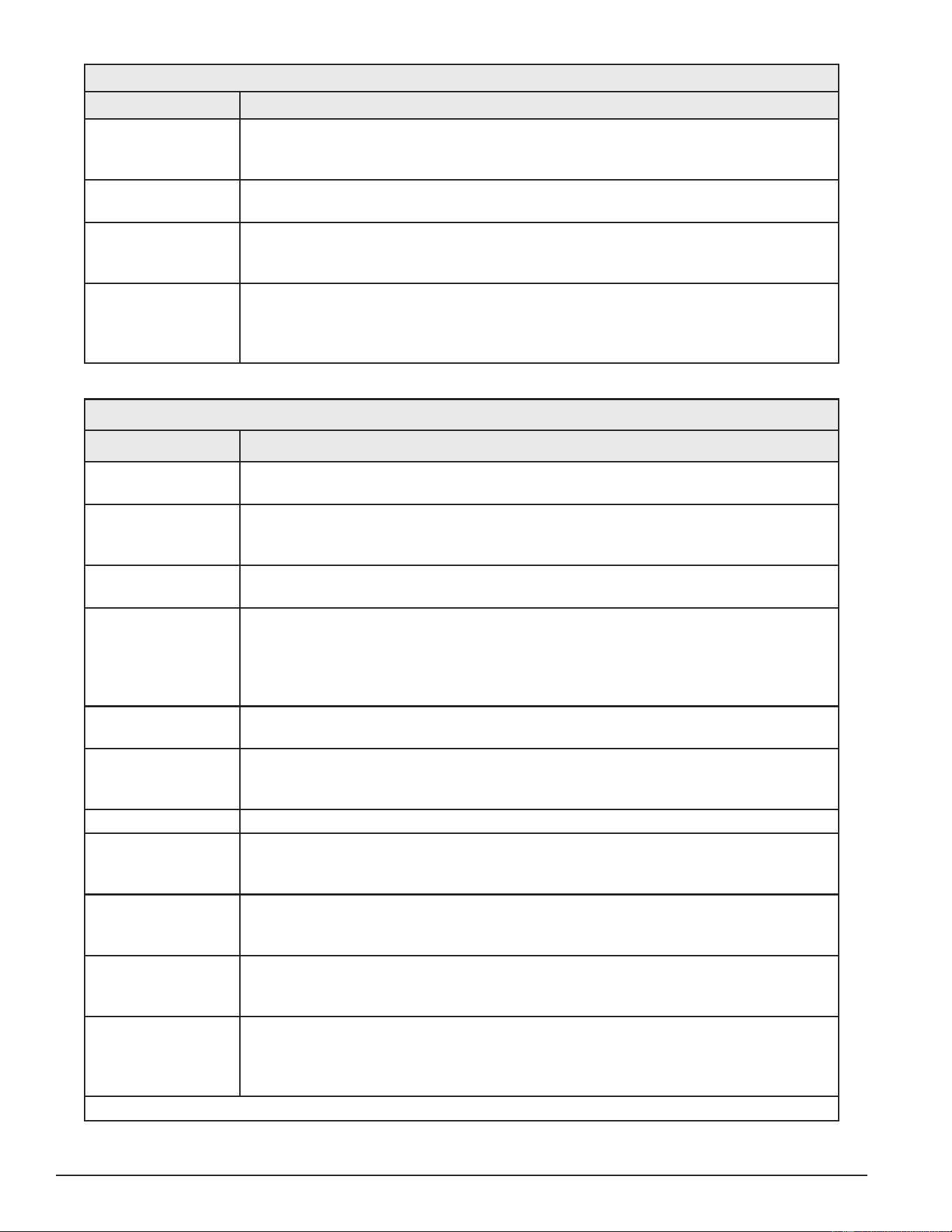
52
Servicing should only be performed by a Qualied Service Technician
Table 13. Operating States
State Description
Standby The water heater is not in an active heating cycle. This usually indicates the tem-
perature in the tank has reached the Operating Set Point and the control system has
terminated the heating cycle.
Heating The control system is in the Heating Mode. At least one heating element has been
energized.
Alert The control system has detected/declared an Alert Condition. The controls system
will continue heating operation. However, a Qualied Service Agent should be con-
tacted to check/service the water heater.
Fault The control system has detected/declared a Fault Condition. The control system
will discontinue heating operation and “lock out.” Power to the water heater must be
cycled off and on to reset the control system. Note; cycling power will not reset the
control system until the condition that caused the Fault has been corrected.
Table 14. Control System Menus
Menus† Description
Temperatures Most commonly accessed menu. Operating Set Point, Differential settings, Tank
Temperature and Tank Probe Offset are located in this menu.
Heater Status Current Operating State/Mode (heating/standby etc) and status (open/closed - on/off
- yes/no) of monitored water heater functions and components are displayed in this
menu.
Economy Mode
Setup
Seven day 24 hour time clock with temperature set back capability to reduce operat-
ing costs during unoccupied or reduced demand periods.
Alarm Output Setup The control system’s CCB (Central Control Board) (page 43) features on board
SPDT (single pole double throw) relay contacts for building EMS (Energy Manage-
ment System) notication of operational conditions such as Fault Conditions and
heating mode status. This menu features a list of user denable conditions for relay
activation.
Display Settings Temperature units (°F or °C), appearance (brightness contrast) and backlight delay
user adjustable settings are located in this menu.
Heater Information Elapsed time of operation, total heating cycle time, heating cycle count, heating
element bank(s) cycle count, and heating bank on time, along with UIM and CCB
software revisions can be viewed in this menu.
Current Fault/Alert Displays any current Alert or Fault messages.
Fault History Retains 9 event history of Fault/Alert messages with time stamp. The Fault History is
useful when dealing with intermittent operational problems or when the customer has
reset the control system prior to a service agent’s arrival.
Fault Occurrence Total accumulated number each individual Fault condition has occurred is displayed
in this menu. This running total of Fault Occurrences can be useful in determining
which (if any) operational problems have been persistent.
Restore Factory
Defaults
This control system feature allows the user to restore control system user settings to
their factory default settings. Alarm Output Setup and Display Settings menu items
ARE NOT changed when factory defaults are restored.
Help Menu Accessible by pressing the corresponding Operational Button from most menus and
screen displays. This menu provides access to instructions and explanations for user
settings, Operating States, Status Icons, manufacturer’s web address, technical sup-
port phone number and service agent contact information.
†. This table shows a list of the control system menus. These menus will be explained in greater detail in the pages that follow.
Printed on 6/17/2020 12:05 PM CT
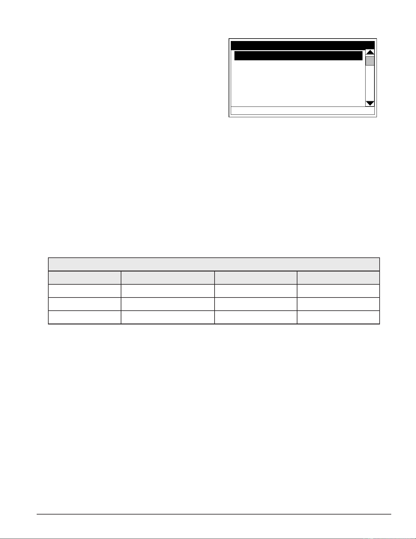
53
Servicing should only be performed by a Qualied Service Technician
TEMPERATURES MENU
Operating Set Point
User adjustable setting 90°F to 190°F range; factory
default is 120°F. When the water temperature sensed
by the control system from the immersion Temperature
Probe reaches the Operating Set Point the control
system will end the heating cycle. A call for heat
will be activated again when the water temperature
drops below the Operating Set Point minus the 1st
Differential Setting.
1st Differential 2°F
2nd Differential 2°F
3rd Differential 2°F
Tank Temperature 105°F
Tank Prob Offset 0°F
HELP
Temperatures
SELECT
Operating Set Point 120°F
BACK
Figure 55. Temperatures Menu Screen
Example: Operating Set Point is 120°F, the 1st Differential Setting is 2°F. A call for heat will be activated when
the sensed water temperature drops to 118°F.
Differential Settings
Adjustable user setting(s) 1°F to 20° range; factory default is 2°F. The water heaters covered in this manual
will have3, 6 or 9 heating elements. Each group of 3 heating elements is one “Bank” of heating elements.
Heating elements are energized in Banks of 3. Each Bank of heating elements will have a Differential Setting
associated with it. Differential Settings are located in the Temperatures Menu.
There is a 1st Differential Setting on all models. There will be one additional Differential Setting visible/adjustable
for each additional Bank of (3) heating elements.
Operating Sequence: With an Operating Set Point of 120°F and all Differential settings at 2°F the On/Off
sequencing of heating element Banks would be as follows:
Table 15. Element Temperature Settings
Bank Number Differential Setting Turn On Temp Turn Off Temp
Bank 1 2°F 118°F 120°F
Bank 2 2°F 116°F 118°F
Bank 3 2°F 114°F 116°F
Tank Temperature
Non adjustable information display. Current water temperature as sensed by the control system from the
immersion Temperature Probe.
Tank Probe Offset
User adjustable setting -5°F to +5°F range; factory default is 0°F. If the current Tank Temperature is sensed
(from the immersion Temperature Probe) at 120°F and the offset is adjusted to -5°F the control system would
calibrate or “offset” the Tank Temperature to 115°F. Heating cycles would then start/stop based on the calibrated
Tank Temperature.
Used to calibrate for slight differences in control system temperature sensing. This can improve the precision
of temperature control in the storage tank and at points of use. This feature can also be used to compensate
for building recirculation loops (hot water returning to the storage tank) that may cause the heating cycle to
terminate prematurely.
Printed on 6/17/2020 12:05 PM CT
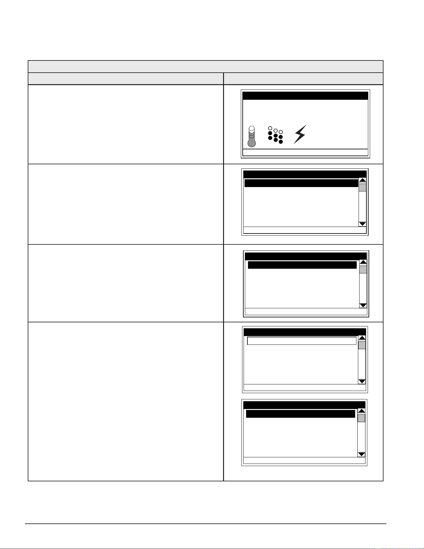
54
Servicing should only be performed by a Qualied Service Technician
TEMPERATURE SETTINGS
The Operating Set Point and the Differential Settings are adjusted in the Temperatures Menu (page 53). The
following instructions explain how to adjust these user settings and navigate the control system menus.
Table 16. Temperature Settings Menu
Action Display
From the Desktop Screen, press the Operational Button
underneath “MENU” to enter the Main Menu. See Control
System Navigation (page 49).
Notice how the text above the Operational Buttons on
the display changes as you navigate through the various
menus and screens.
Tank Temperature 114°F
Operating Setpoint 120°F
Status: Standby
HELP
MODEL INFORMATION
MENU
Friday
5:00 PM
Normal Mode
With Temperatures selected (highlight in black) in the Main
Menu, press the Operational Button underneath “SELECT”
to enter the Temperatures Menu.
If Temperatures is not selected use the Up and Down
buttons to select this menu item.
Heater Status
Economy Mode Setup
Alarm Output Setup
Display Settings
HELP
MAIN MENU
SELECT
Temperatures
BACK
With the Operating Set Point selected (highlight in black)
in the Temperatures Menu, press the Operational Button
underneath “CHANGE” to activate the adjustment mode
for this menu item.
1st Differential 2°F
2nd Differential 2°F
3rd Differential 2°F
Tank Temperature 105°F
Tank Prob Offset 0°F
HELP
Temperatures
SELECT
Operating Set Point
120°F
BACK
Press the Up and Down buttons to adjust the Operating
Set Point to the desired setting.
Press the Operational Button underneath “UPDATE” to
conrm the new setting. Press the Operational Button
underneath “CANCEL” to discard the new setting and
retain the previous setting.
The new Operating Set Point value should now be
displayed as the current value.
Note: Use this same procedure to adjust the Differential
settings and the Tank Probe Offset in the
Temperatures Menu.
This same procedure is used to change user settings in
other control system menus.
1st Differential 2°F
2nd Differential 2°F
3rd Differential 2°F
Tank Temperature 105°F
Tank Prob Offset 0°F
CANCEL
Temperatures
UPDATE
Operating Set Point
140°F
1st Differential 2°F
2nd Differential 2°F
3rd Differential 2°F
Tank Temperature 105°F
Tank Prob Offset 0°F
HELP
Temperatures
CHANGE
Operating Set Point
140°F
BACK
Printed on 6/17/2020 12:05 PM CT
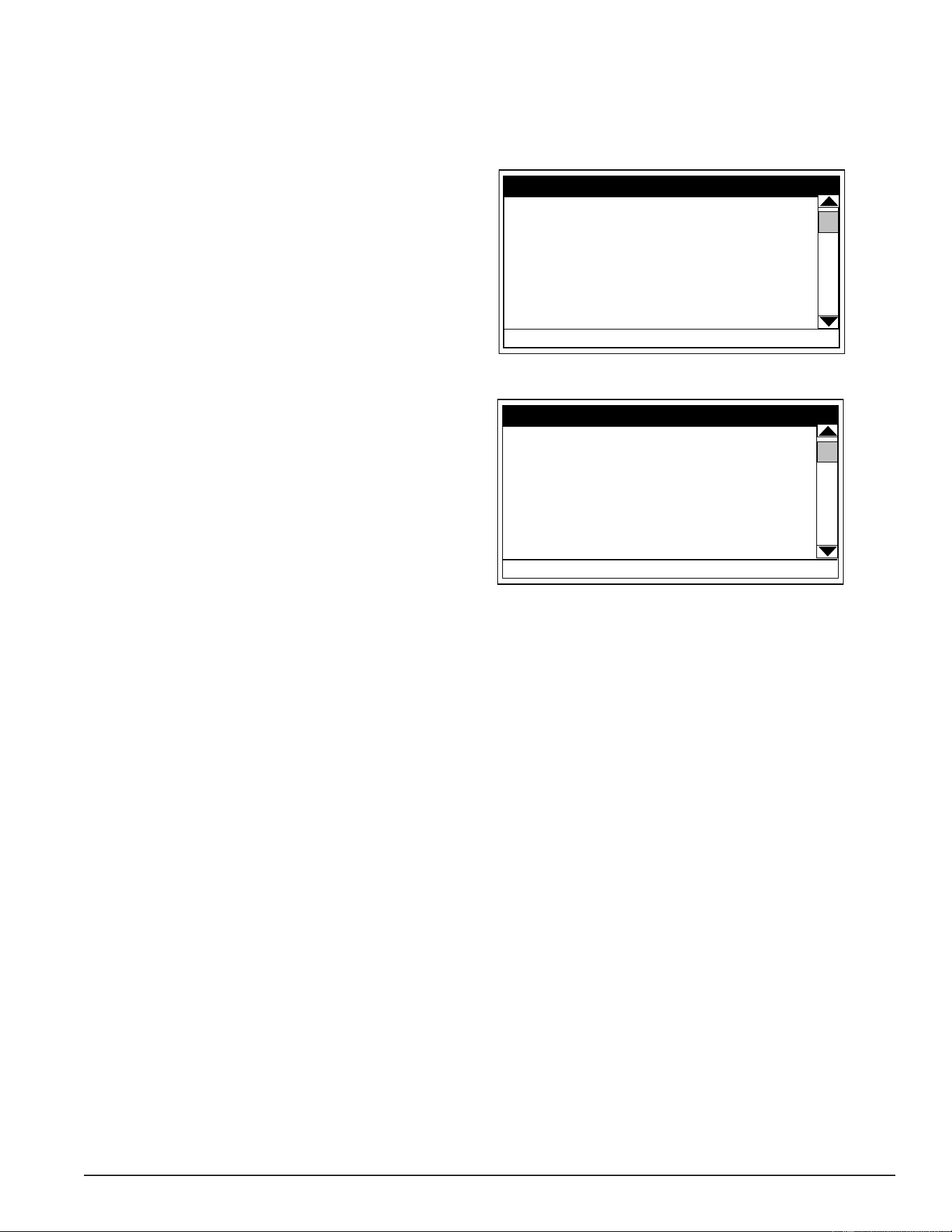
55
Servicing should only be performed by a Qualied Service Technician
HEATER STATUS MENU
This menu displays non adjustable operational information. Use the Up & Down Buttons to navigate to the
bottom and top of this menu.
Status
Displays the current Operating State of the control
system. For example, Heating, Standby, or Fault. See
Table 13 (page 52).
Element Banks On #
Displays the current number of heating element
Banks the control system has energized. Each Bank
of elements contains 3 heating elements.
ECO Contact
Displays the current state of the ECO high temperature
limit switch contacts. The ECO switch is located inside
the immersion Temperature Probe (two red wires).
Enable / Disable 1 & 2
Displays the current state, open or closed, of the two
Enable/Disable circuits (J7 socket on the CCB (page
43)) provided for external supervisory controls such
as building EMS (Energy Management System). Both
of these Enable/Disable circuits must be closed to
“enable” heating operation. If either Enable/Disable
circuit is open heating will be “disabled.” A plug with
two jumper wires is installed from the factory in the
CCB J7 socket to enable heating operation when
external controls are not in use.
Top Of Menu
Status Heating
Elements On 1
ECO Contact Closed
Enable / Disable 1 Closed
Enable / Disable 2 Closed
Element Bank 1 On Yes
Element Bank 2 On No
HELP
Heater Status
CHANGE
BACK
Bottom Of Menu
Enable / Disable 1 Closed
Enable / Disable 2 Closed
Element Bank 1 On Yes
Element Bank 2 On No
Element Bank 3 On No
Alarm Condidion No
Alarm Relay Output Open
HELP
Heater Status
BACK
Service Note: If a supervisory control(s) is used to enable/disable heating operation, install eld wiring
between the J7 socket on the CCB and a set of “dry contacts” on the external control per
all applicable building codes. This is a switching circuit only: DO NOT apply any external
voltage or connect any load (IE: relay coil) to either circuit.
Element Bank On
Displays the on/off status of each heating element. Yes = On, No = Off.
Alarm Condition
Displays the status of the user denable Alarm Output function. See Alarm Output Settings (page 61). Yes =
alarm condition has been met, No = alarm condition has not been met.
Alarm Relay Output
Displays the state of the normally open contacts of the Alarm Output relay. This relay with J3 contacts on the
CCB, is used for building EMS (Energy Management System) notication of operational conditions such as
Fault conditions and heating mode status. See Central Control Board (CCB) (page 43)
Printed on 6/17/2020 12:05 PM CT
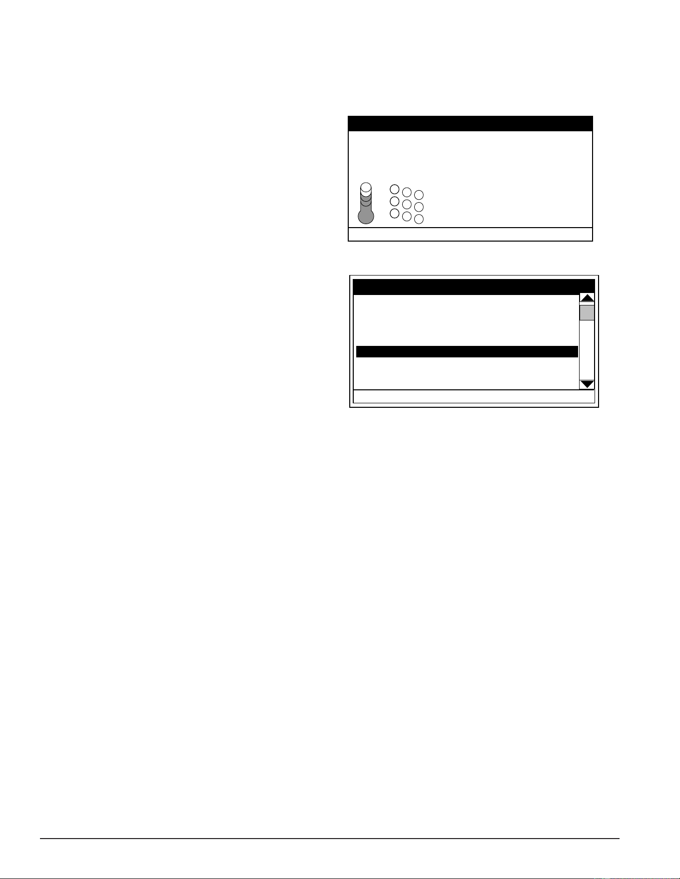
56
Servicing should only be performed by a Qualied Service Technician
ECONOMY MODE SETUP MENU
This menu contains settings used to establish an “Economy Set Point” and “Economy Mode” operating periods.
This control system feature can help reduce operating costs during unoccupied or low demand periods.
Setpoint Adjustment
Adjustable user setting (2°F to 50°F - factory default
is 20°F) the control system uses to calculate the
“Economy Set Point.” The Economy Set Point =
normal Operating Set Point minus the programmed
Setpoint Adjustment value. The Economy Set
Point is the water temperature the control system
maintains during programmed Economy Mode time
periods. “Economy Set Point” is displayed instead of
“Operating Set Point” and “Economy Mode” appears
beneath the current time on the Desktop Screen
during Economy Mode time periods.
Current Time
Seven Day 24 hr clock. Use this menu item to set the
current time and day of the week.
Current day and time are not set from the factory.
“Clock Not Set” will be displayed on the Desktop until
the time/day has been initially set. Note: the time will
not self adjust for Daylight Savings time.
Desktop Screen During Economy Mode
Tank Temperature 120°F
Operating Setpoint 100°F
Status: Standby
HELP
MODEL INFORMATION
MENU
Friday
5:00 PM
Normal Mode
Economy Mode Setup Menu
Current Time Mon 5:00 PM
Heater In Economy Mode No
Sun Economy Mode All Day
Mon Normal 7:30 AM to 8:00 PM
Tue Normal All Day
Wed Normal All Day
HELP
Economy Mode Setup
CHANGE
Setpoint Adjustment 20
BACK
Heater In Economy Mode
Displays whether the control system is currently operating in Economy Mode or not.
Daily Operating Mode (Sun - Mon - Tue - Wed - Thu - Fri - Sat)
Seven daily sub menus are listed at the bottom of the Economy Mode Setup menu. There are 3 Operating
Modes available in each daily sub menu; “Normal Operation All Day” - “Economy Mode All Day” and “Normal
Operation Between.” Only one Operating Mode can be active at a time, the factory default is Normal Operation
All Day.
Normal Operation All Day: When this operating mode is active the normal Operating Set Point (Temperatures
Menu (page 53) is used for the entire day.
Economy Mode All Day: When this operating mode is active the Economy Set Point is used for the entire
day. Economy Set Point = normal Operating Set Point minus the programmed Setpoint Adjustment value.
Normal Operation Between: When this operating mode is active there will also be start and stop times to
program. The normal Operating Set Point is used between the programmed start and stop times and the
Economy Set Point will be in effect during the rest of the day. There is one programmable start and stop time
event per day.
Printed on 6/17/2020 12:05 PM CT
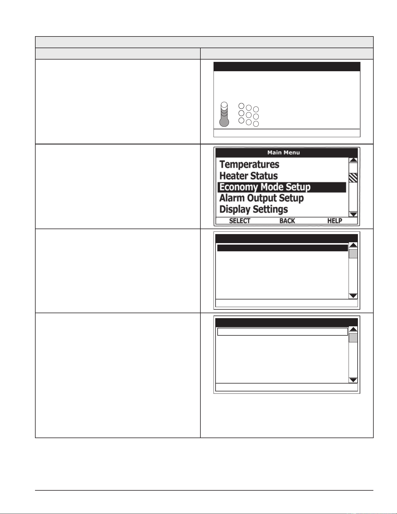
57
Servicing should only be performed by a Qualied Service Technician
Economy Mode Settings Setpoint Adjustment Value
Table 17. Setpoint Adjustment Value
Action Display
From the Desktop screen, press the Operational
Button underneath “MENU” to enter the Main Menu.
See Control System Navigation (page 49).
Notice how the text above the Operational Buttons
on the display changes as you navigate through the
various menus and screens.
Tank Temperature 120°F
Operating Setpoint 100°F
Status: Standby
HELP
MODEL INFORMATION
MENU
Friday
5:00 PM
Normal Mode
Use the Up/Down buttons to select (highlight in
black) the Economy Mode Setup menu from
the Main Menu. Press the Operational Button
underneath “SELECT” to enter the Economy Mode
Setup menu.
Use the Up/Down buttons to select (highlight in
black) Setpoint Adjustment. Press the Operational
Button underneath “CHANGE” to activate the
adjustment mode for the Setpoint Adjustment value.
Current Time Wed 4:19 PM
Heater In Economy Mode No
Sun Normal All Day
Mon Normal All Day
Tue Normal All Day
Wed Normal All Day
HELP
Economy Mode Setup
CHANGE
Setpoint Adjustment 40
BACK
Use the Up/Down buttons to change the Setpoint
Adjustment to the desired value. The Setpoint
Adjustment value is adjustable from 2°F to 50°F.
The factory default is 20°F.
Notice how the text above the Operational Buttons
on the display changes to “UPDATE” & “CANCEL”
when the adjustment mode is activated and how
the current value is outlined rather than highlighted
in black.
Press the Operational Button underneath “UPDATE”
to enter and conrm the new value. Pressing the
Operational Button underneath “CANCEL” would
discard the new value and retain the previous value.
Current Time Wed 4:19 PM
Heater In Economy Mode No
Sun Normal All Day
Mon Normal All Day
Tue Normal All Day
Wed Normal All Day
CANCEL
Economy Mode Setup
UPDATE
Setpoint Adjustment 20
Printed on 6/17/2020 12:05 PM CT
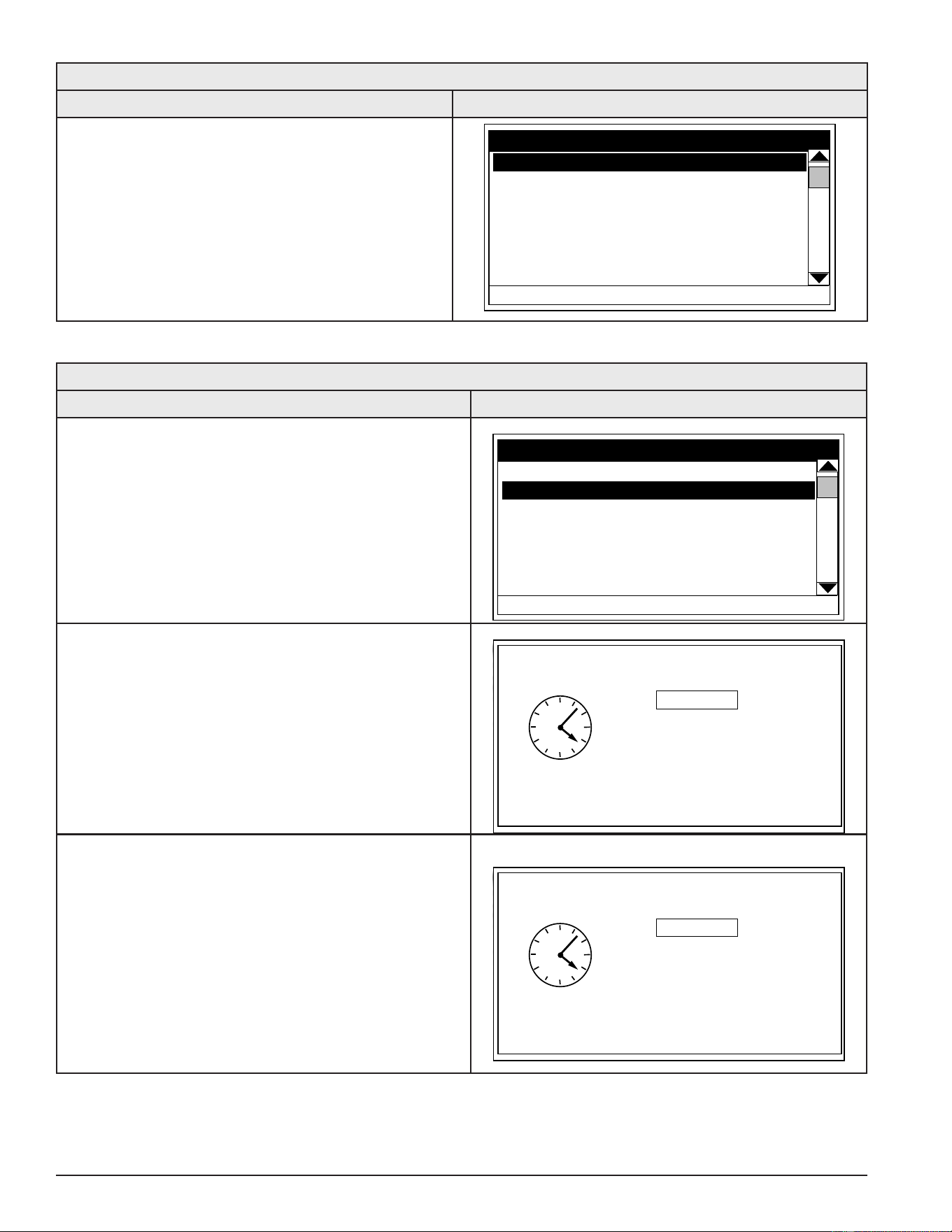
58
Servicing should only be performed by a Qualied Service Technician
Table 17. Setpoint Adjustment Value
Action Display
The new Setpoint Adjustment value should now be
displayed as the current value.
Current Time Wed 4:19 PM
Heater In Economy Mode No
Sun Normal All Day
Mon Normal All Day
Tue Normal All Day
Wed Normal All Day
HELP
Economy Mode Setup
CHANGE
BACK
Setpoint Adjustment 20
Table 18. Time Clock Settings
Action Display
From the Desktop Screen navigate to the Economy
Mode Setup menu - see page 65 for instructions.
Use the Up/Down buttons to select (highlight in black)
Current Time sub menu. Press the Operational Button
underneath “CHANGE” to enter the Current Time sub
menu.
Current Time Wed 4:19 PM
Heater In Economy Mode No
Sun Normal All Day
Mon Normal All Day
Tue Normal All Day
Wed Normal All Day
HELP
Economy Mode Setup
CHANGE
BACK
Setpoint Adjustment 20
Use the Up/Down buttons to select the “Weekday”
setting.
Press the Operational Button underneath “CHANGE”
to activate the adjustment mode for this setting.
CANCEL
ACCEPT
Current Time
Weekday: Monday
Time: 4:19 PM
Press the Up and Down buttons to adjust the Weekday
setting to the current day.
Notice how the text above the Operational Buttons on
the display changes to “ACCEPT” & “CANCEL” when
the adjustment mode is activated and how the current
setting is outlined rather than highlighted in black.
Press the Operational Button underneath “ACCEPT”
to enter and conrm the new setting. Pressing the
Operational Button underneath “CANCEL” would
discard the new setting and retain the previous setting.
CANCEL
ACCEPT
Current Time
Weekday: Monday
Time: 4:19 PM
Printed on 6/17/2020 12:05 PM CT
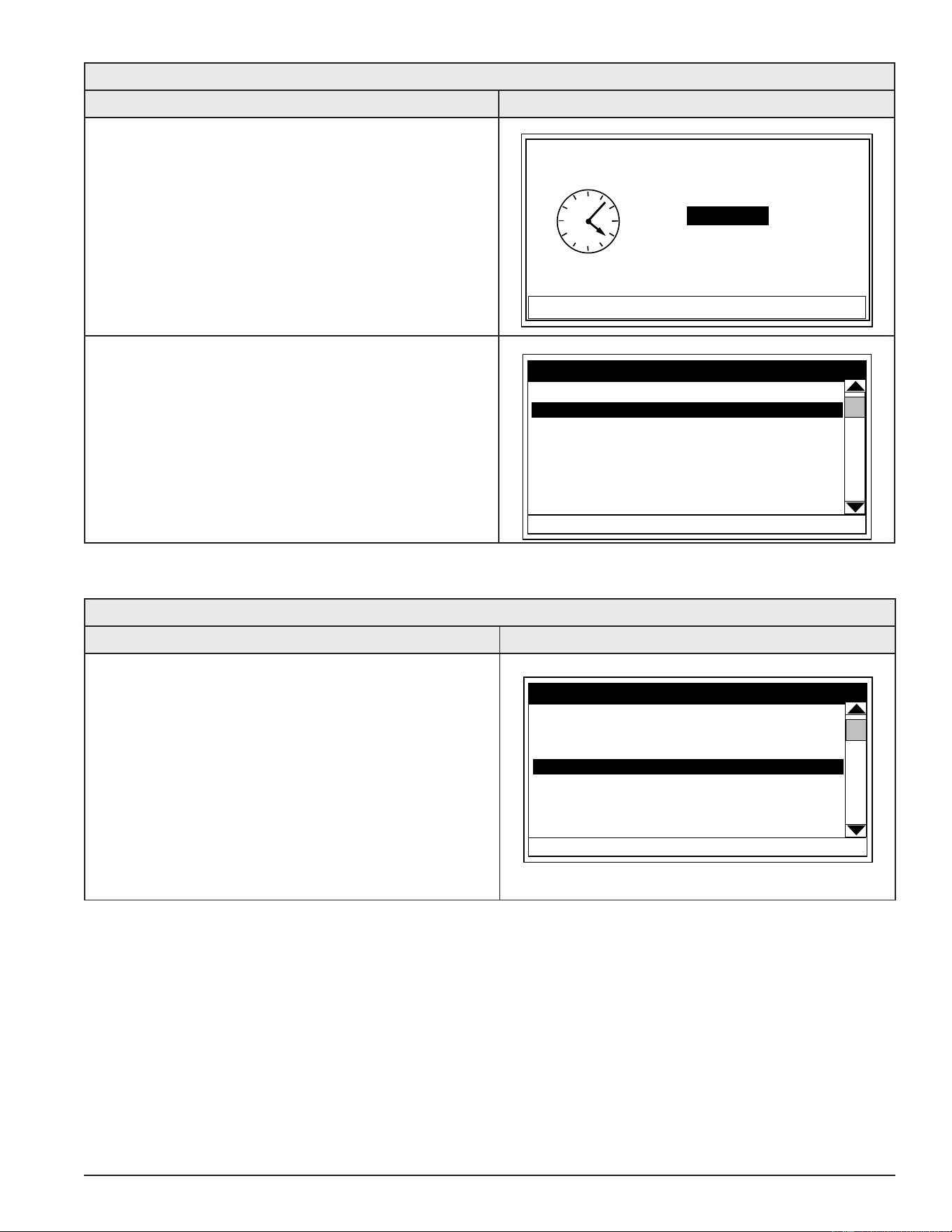
59
Servicing should only be performed by a Qualied Service Technician
Table 18. Time Clock Settings
Action Display
Use the Up/Down and the CHANGE/ACCEPT
Operational Buttons to individually select and change
the remaining time settings (Hour, Minutes, AM/PM) to
the current time in the same way as outlined above.
When nished making changes press the Operational
Button underneath “BACK” to conrm all new settings
and update the control system. The display will
automatically return to the Economy Mode Setup
menu.
BACK
CHANGE
Current Time
Weekday: Monday
Time: 5:00 PM
Sending Updates to CCB....
The new settings should be displayed as the Current
Time.
Current Time Mon 5:00 PM
Heater In Economy Mode No
Sun Normal All Day
Mon Normal All Day
Tue Normal All Day
Wed Normal All Day
HELP
Economy Mode Setup
CHANGE
Setpoint Adjustment 20
BACK
Table 19. Daily Operating Mode Setting
ACTION DISPLAY
Economy Mode All Day:
From the Economy Mode Setup menu use the Up/Down
buttons to select (highlight in black) the Daily sub menu
for “Sun.” Press the Operational Button underneath
“CHANGE” to enter this menu.
See “Time Clock” settings Economy Mode Setup Menu (page
56) for instructions on navigating to the Economy
Mode Setup menu.
Current Time Mon 5:00 PM
Heater In Economy Mode No
Sun Normal All Day
Mon Normal All Day
Tue Normal All Day
Wed Normal All Day
HELP
Economy Mode Setup
CHANGE
Setpoint Adjustment 20
BACK
Printed on 6/17/2020 12:05 PM CT
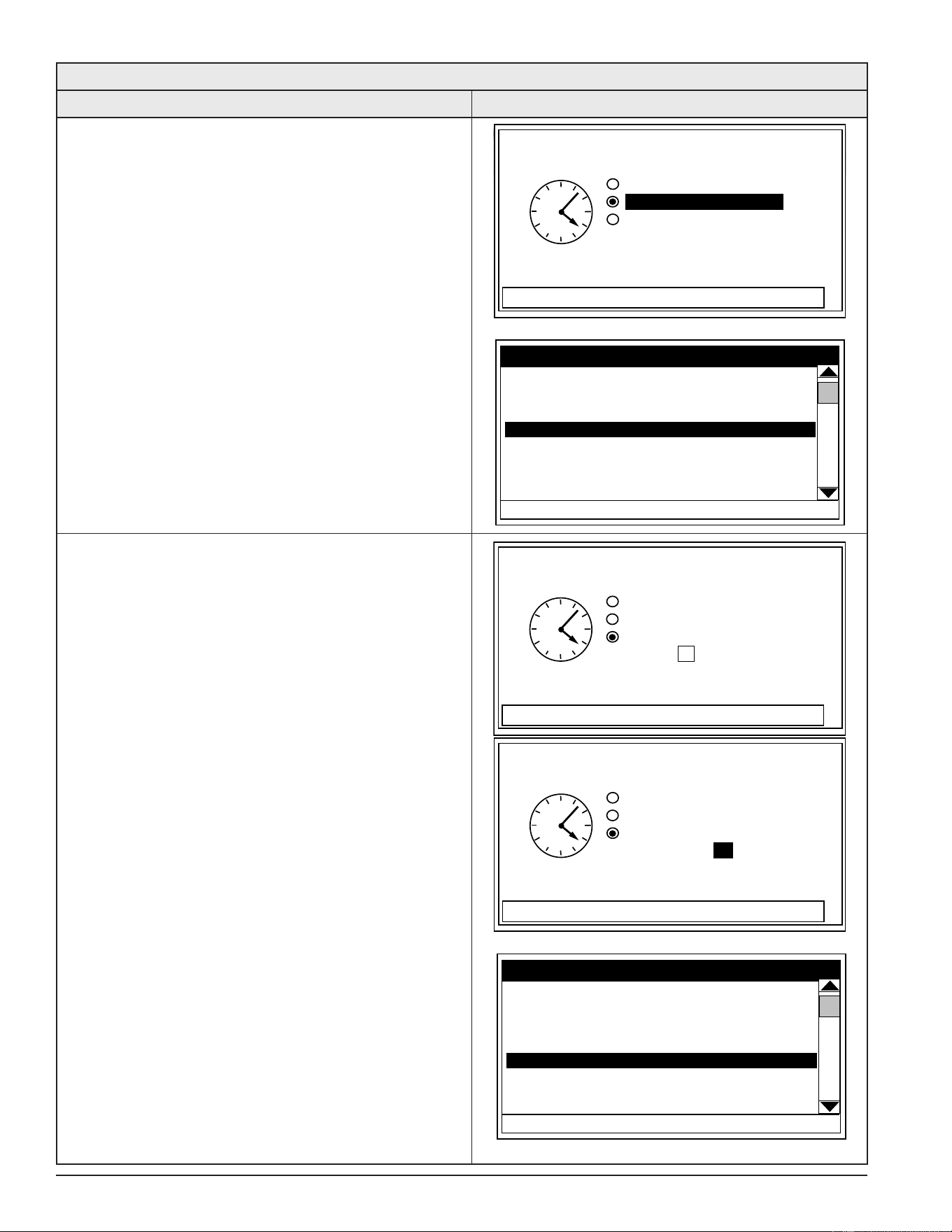
60
Servicing should only be performed by a Qualied Service Technician
Table 19. Daily Operating Mode Setting
ACTION DISPLAY
Use the Up/Down buttons to select (highlight in black)
the “Economy Mode All Day” setting.
Press the Operational Button underneath “SELECT”
to change from the factory default Normal Operation
All Day setting to the Economy Mode All Day setting.
Press the Operational Button underneath “BACK” to
conrm the new setting and update the control system.
You will be returned to the Economy Mode Setup menu.
The new setting should now be displayed for Sun.
BACK
SELECT
Sunday
Sending Updates to CCB....
Normal Operation All Day
Economy Mode All Day
Normal Operation Between:
Current Time Mon 5:00 PM
Heater In Economy Mode No
Sun Economy Mode All Day
Mon Normal All Day
Tue Normal All Day
Wed Normal All Day
HELP
Economy Mode Setup
CHANGE
Setpoint Adjustment 20
BACK
Normal Operation Between:
From the Economy Mode Setup menu Use the Up/
Down and CHANGE buttons to enter the Mon sub menu
as described above.
Use the Up/Down buttons to select (highlight in black)
the “Normal Operation Between” setting. Press the
Operational Button underneath “SELECT” to change
the operating mode for Monday to Normal Operation
Between. Note that when this setting is selected Start
and Stop time user settings appear on the display.
Use the Up/Down buttons to navigate between the
Start and Stop time Hour, Minutes and AM/PM settings.
With each item selected press the Operational Button
underneath “CHANGE” to activate the adjustment
mode for each setting. Use the Up/Down buttons to
change the value to the desired setting.
Press the Operational Button underneath “ACCEPT” to
enter the new setting or “CANCEL” to discard the new
setting and retain the previous setting.
Press the Operational Button underneath “BACK” when
nished to conrm the new settings and update the
control system. The display will return to the Economy
Mode Setup menu with the new settings shown for Mon.
CANCEL
ACCEPT
Monday
Start: 7:00 PM
Stop: 8:00 PM
Sending Updates to CCB....
Normal Operation All Day
Economy Mode All Day
Normal Operation Between:
BACK
CHANGE
Monday
Normal Operation All Day
Economy Mode All Day
Normal Operation Between:
Start: 7:30 AM
Stop: 8:00 PM
Sending Updates to CCB....
Current Time Mon 5:00 PM
Heater In Economy Mode No
Sun Economy Mode All Day
Mon Normal 7:30 am to 8:00 PM
Tue Normal All Day
Wed Normal All Day
HELP
Economy Mode Setup
CHANGE
Setpoint Adjustment 20
BACK
Printed on 6/17/2020 12:05 PM CT
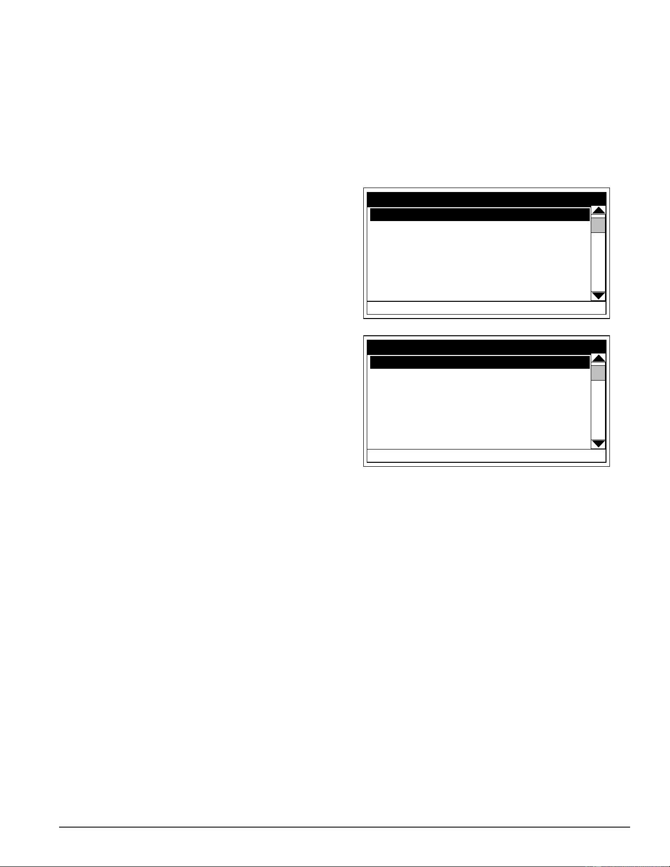
61
Servicing should only be performed by a Qualied Service Technician
ALARM OUTPUT SETUP MENU
Permits user to set the condition (from a list of options) for when the CCB’s integral alarm output relay will be
energized. Alarm relay connections (common, normally open, normally closed) are located on the J3 terminal
strip on the CCB (page 43). Alarm output relay contacts are capable of switching 1 amp maximum at 120 VAC.
The alarm relay operates in the background according to the settings in this menu and is not capable of
disabling water heater operation. The alarm relay is used for external notication/ verication of various
operational conditions such as Fault conditions and heating mode status. This relay can be used with building
EMS (Energy Management System) and other external supervisory controls.
Output Function
Adjustable user setting. Available options for the Alarm
Output Function setting are:
Heating Mode: Used for heating mode on/off status
notication.
Enable / Disable Closed: Used for notication or
verication of the enable/ disable circuits open/closed
status. There are two enable/disable circuits available
for external supervisory control(s) at the J7 socket.
See Central Control Board (CCB) (page 43). Enable/
disable circuit(s) status can be viewed in Heater Status
Menu (page 55).
Temp < Heater SP: Used for external notication
when current tank temperature drops below Operating
Set Point.
HELP
Alarm Output Setup
CHANGE
BACK
Output Function Fault
Alarm SP 120ºF
HELP
Alarm Output Setup
CHANGE
BACK
Output Function Temp < Alarm SP
Alarm SP 120ºF
Temp < Alarm SP: Used for external notication when current tank temperature drops below the programmable
Alarm SP.
Fault or Alert: Used for external notication whenever a Fault or Alert condition is active.
Fault: Used for notication whenever a Fault condition is active.
Disabled: Disables the Alarm Relay Output Function - this is the factory default setting.
Alarm SP - (Alarm Set Point)
Adjustable user setting (90°F to 190°F) the control system uses for the “Temp < Alarm SP” function described
above. This setting has no effect with any other Alarm Output functions.
Alarm Output Settings
Changing the user settings in this menu is done using the same method outlined in Temperature Settings (page
54).
Service Note: Adjustable user settings in the Alarm Output Setup menu are unaffected by the Restore
Factory Defaults function. See Restore Factory Defaults Menu (page 65).
Printed on 6/17/2020 12:05 PM CT
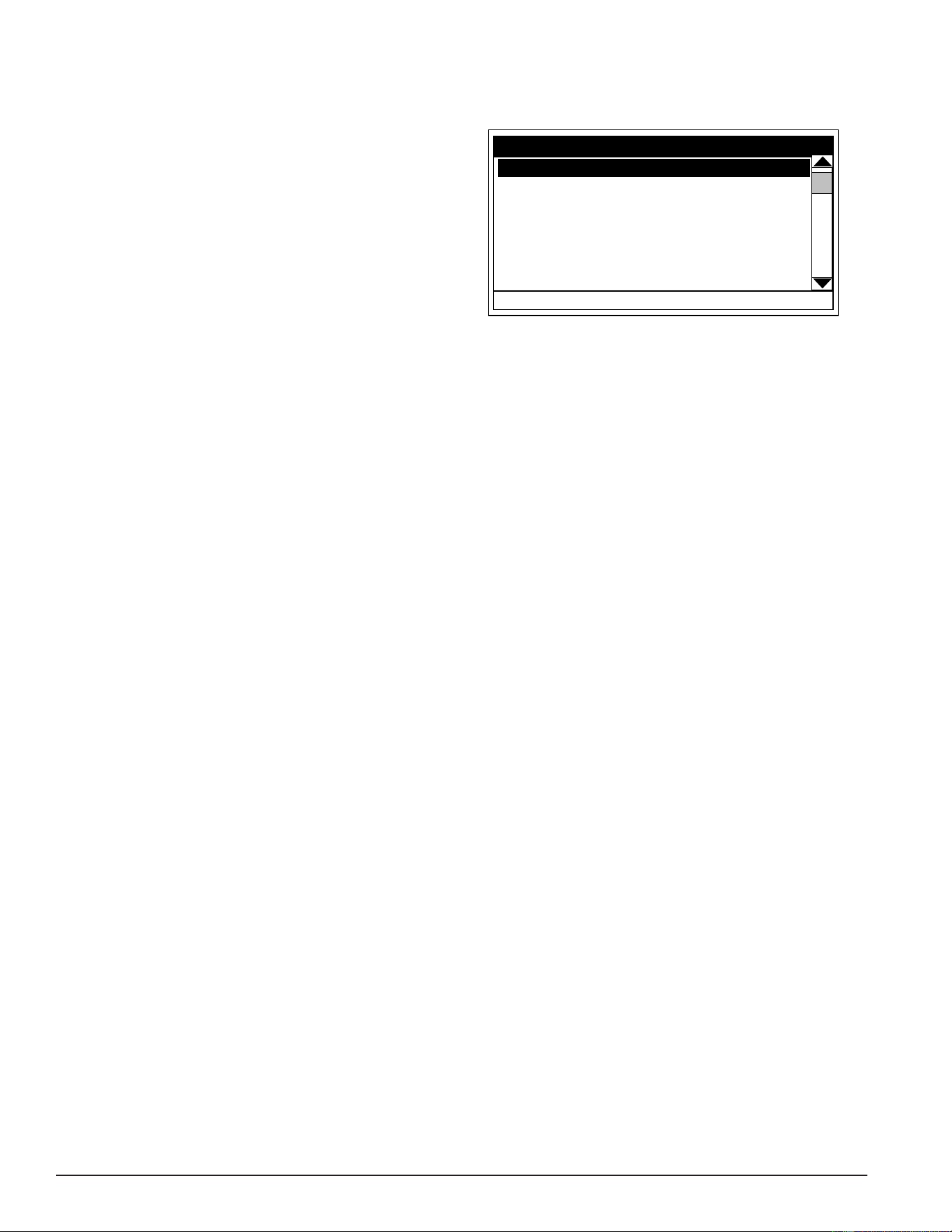
62
Servicing should only be performed by a Qualied Service Technician
DISPLAY SETTINGS MENU
Permits user to set display options for viewing information on the UIM’s LCD screen.
Temperature Units
Adjustable user setting that changes temperature
units display to Celsius °C or Fahrenheit °F.
Backlight Delay
Adjustable user setting that determines how long the
UIM’s LCD backlight remains illuminated after a key
has been pressed.
Available settings are; Always Off, 10, 30 or 60
seconds and Always On.
HELP
Display Settings
CHANGE
BACK
Temperature Units ºF
Backlight Delay 30s
Contrast 20%
Contrast
Adjustable user setting to adjust the UIM’s LCD screen contrast between text and background.
Display Settings
Changing the user settings in this menu is done using the same methods outlined in Commercial Electric water
heaters (page 54).
Service Note: Adjustable user settings in the Display Settings menu are unaffected by Restore Factory
Defaults Menu (page 65).
Printed on 6/17/2020 12:05 PM CT
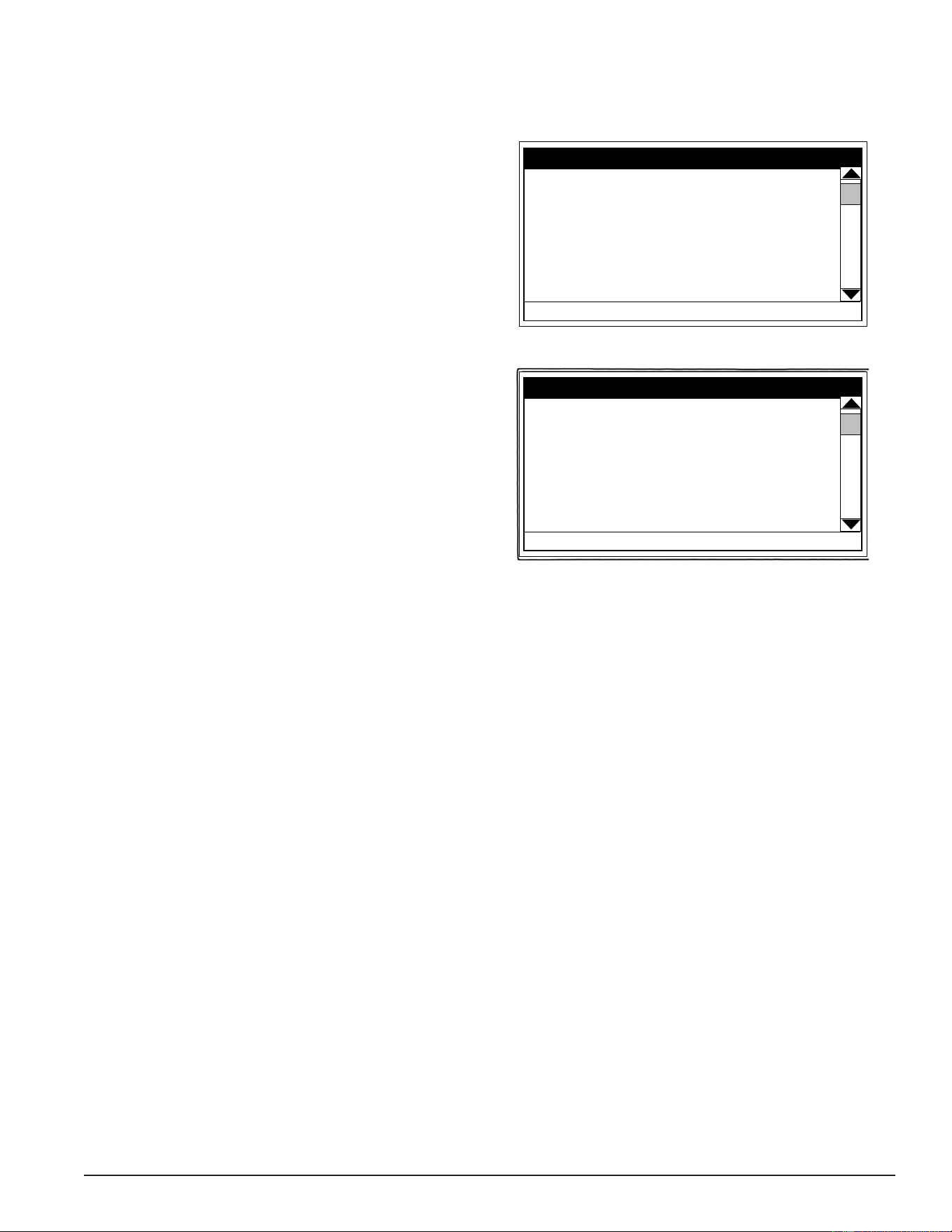
63
Servicing should only be performed by a Qualied Service Technician
HEATER INFORMATION MENU
This menu displays non adjustable operational information.
Elapsed Time
Total accumulated time the control system (water
heater) has been energized.
Total Heating Time
Total accumulated time the control system has been
in the heating mode. IE: any heating element(s) has
been energized.
Bank # Cycles
Total accumulated count of heating cycles for each
bank of heating elements.
Bank # On Time
Total accumulated heating on time for each bank of
heating elements.
CCB Version
Software version for Central Control Board. See Central
Control Board (CCB) (page 43).
Top Of Menu
Elapsed Time
7 days 18 hrs 35 mins
Total Heating Time
2 days 46 mins
Cycle Count 00000042
Element 1 Cycles 00000035
Element 1 On Time
HELP
Heater Information
BACK
Bottom Of Menu
Element 2 On Time
1 days 4 hrs 44 mins
Element 3 Cycles 00000025
Element 3 On Time
8 hrs 30 mins
CCB Version 0.00
UIM Version 0.00
HELP
Heater Information
BACK
UIM Version
Software version for User Interface Module.
Printed on 6/17/2020 12:05 PM CT
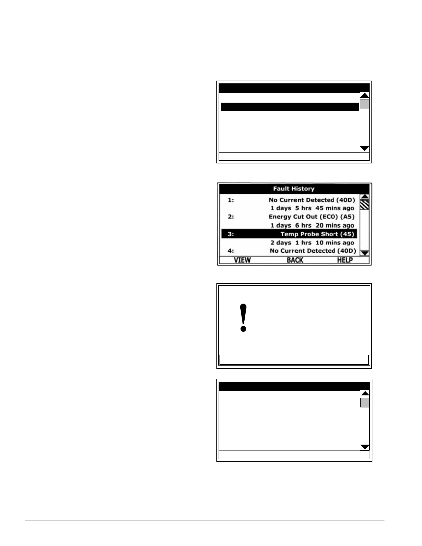
64
Servicing should only be performed by a Qualied Service Technician
CURRENT FAULT / ALERT MENU
This menu displays non adjustable operational information. With the Fault History sub menu selected in Main
Menu, press the Operational Button underneath “SELECT” to display the current Fault or Alert message. If
there is not a Fault or Alert condition currently active, “(none)” is displayed to the right of this menu.
Fault History Menu
This menu displays non adjustable operational
information. The control system records and stores
the last 9 Fault and Alert messages in chronological
order in this menu. The most recent will be at the top
of the list. A time stamp is displayed below each listed
Fault and Alert message showing when the Fault or
Alert condition occurred.
The Fault History is useful when dealing with
intermittent operational problems or when the
customer has reset the control system prior to a
service agent’s arrival.
With a Fault or Alert item selected, press the
Operational Button underneath “VIEW” to display
the details for the Fault or Alert message. The Fault/
Alert message screen displays a brief description of
the condition, contact information, and access to the
Advanced Service information sub menu.
Fault Occurrence Menu
The total accumulated number of each individual Fault
condition that has occurred is displayed in this menu.
This running total of Fault Occurrences can be useful
in determining which (if any) operational problems
have been persistent.
Main Menu - Current Fault Selected
HELP
Main Menu
SELECT
BACK
Heater Information
Current Fault (45)
Fault History
Fault Occurrence
Restore Factory Defaults
Fault History Menu
Current / History Fault Message
ADVANCED
Temp Probe Short
Fault occurred 14 mins ago
There is a problem with the
temperature probe.
Call a service professional:
Paul Stewart
(xxx) xx - xxxx
(press [DOWN] for more....)
BACK
Fault Occurrence Menu
HELP
Fault Occurrence
BACK
ECO 1
No Current Detected 3
LWCO 2
Tank Temp Probe
Powered Anode Fail
CCB Hardware
Model Faults
Printed on 6/17/2020 12:05 PM CT
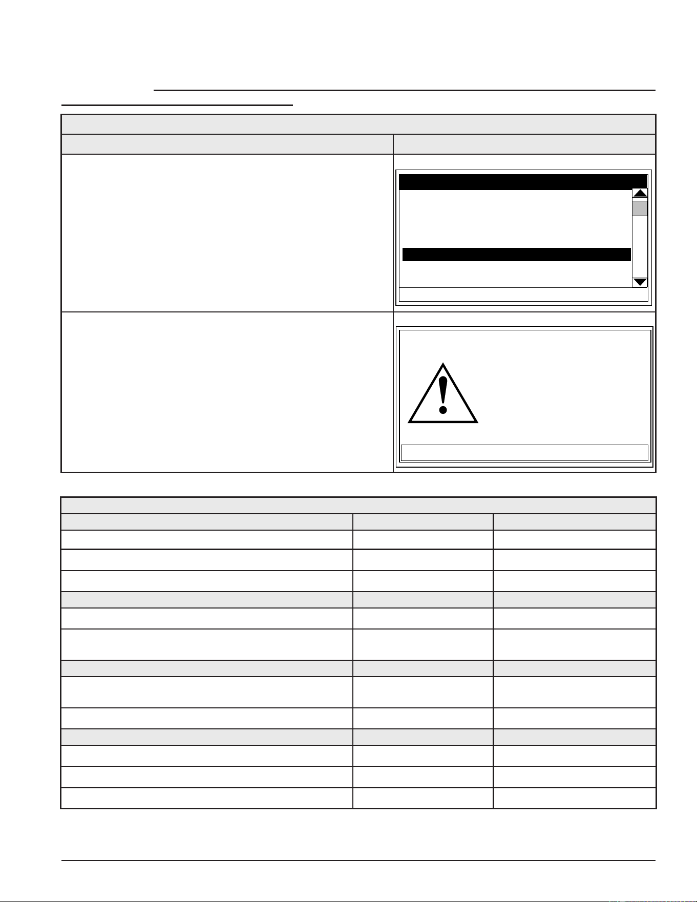
65
Servicing should only be performed by a Qualied Service Technician
RESTORE FACTORY DEFAULTS MENU
This control system menu allows the user to restore most of the control system’s user settings to their factory
default settings. User settings in the Alarm Output Setup and Display Settings menus are unaffected
by executing Restore Factory Defaults.
Table 20. Restore Factory Defaults
ACTION DISPLAY
From the Main Menu, use the Up/Down buttons to select
(highlight in black) the “Restore Factory Defaults” menu.
Press the Operational Button underneath “SELECT.” The
Restore Factory Defaults menu will be displayed.
HELP
Main Menu
SELECT
BACK
Heater Information
Current Fault (45)
Fault History
Fault Occurrence
Restore Factory Defaults
From the Restore Factory Defaults menu, press the
Operational Button underneath “YES.” The display will
show text conrming the factory default settings have been
restored.
Press the Operational Button underneath “BACK” to exit the
Restore Factory Defaults menu.
NO
YES
Restore Factory Defaults
Are you sure you want to
restore the system to factory
defaults?
Table 21. Factory Default User Settings
TEMPERATURES MENU DEFAULT SETTING ADJUSTABLE RANGE
Operating Set Point 120°F (49°C) 90ºF to 190ºF (32°C to 88°C)
Differential Settings 2°F (1°C) 1°F to 20°F (1°C to 11°C)
Tank Probe Offset 0°F (0°C) -5°F to +5°F (-3°C to +3°C)
ECONOMY MODE SETUP MENU DEFAULT SETTING ADJUSTABLE RANGE
Setpoint Adjustment 20°F (11°C) 2°F to 50°F (1°C to 28°C)
Daily Operating Mode Normal Operation All Day See Economy Mode Setup Menu
(page 56).
ALARM OUTPUT SETUP MENU DEFAULT SETTING ADJUSTABLE RANGE
Alarm Output Function Disabled See Alarm Output Setup Menu
(page 61).
Alarm SP 100 (38°C) 90ºF to 190ºF (32°C to 88°C)
DISPLAY SETTINGS MENU DEFAULT SETTING ADJUSTABLE RANGE
Temperature Units °Fahrenheit °Fahrenheit or °Celsius
Backlight Delay 10 Seconds Always off/on, 10, 30, 60 Sec
Contrast 30% 20% to 100%
Printed on 6/17/2020 12:05 PM CT

66
Servicing should only be performed by a Qualied Service Technician
TROUBLESHOOTING
COMMON SERVICE PROBLEMS
NO HOT WATER
1. Hot water supply valve to xtures turned off; cold water supply valve to water heater turned off.
2. Check power to the water heater. See Single- and Three-Phase Power (page 13).
3. Check thermostat/ECO controls on Surface Mount Control Models. See Fuses (page 18) and Surface Mount
Thermostats (page 19).
4. Check Operating Set Point (page 53) and Differential Settings (page 53).
5. Check all fuses - see Fuses (page 18).
6. Check heating elements. See Heating Elements (page 21).
7. Ensure both enable/disable circuits at the CCB’s J7 plug/socket connection are closed circuits. See CCB
Enable/Disable Circuit(s) Test (page 46) and Heater Status Menu (page 55).
NOT ENOUGH HOT WATER
1. Water heater may be undersized.
2. Check thermostat/ECO controls on surface mount control models. See Surface Mount Control Models (page
8) and Thermostat & ECO Test (page 20).
3. Check Operating Set Point (page 53) and Differential Settings (page 53).
4. On electronic control models, ensure the time is set correctly (daylight savings etc) and ensure that the water
heater is not in the Economy Mode during peak demand periods. See Economy Mode Setup Menu (page 56).
5. Ensure the power supply matches the listed voltage on the water heater rating plate. See Single- and Three-
Phase Power (page 13).
6. Check hot water supply piping for leaks or restrictions: lime/scale - valve partially closed.
7. Check all fuses - see Fuses (page 18).
8. Check heating elements. See Heating Elements (page 21).
9. Check contactors on electronic control models. See Contactors (page 30).
10. Check both enable/disable circuits at the CCB’s J7 socket on Electronic Control Models. If either/both circuits
are being used by a supervisory control(s) check that control’s settings to ensure it is not disabling heating
operation during occupied/normal demand periods. See CCB Enable/Disable Circuit(s) Test (page 46) and Heater
Status Menu (page 55).
Printed on 6/17/2020 12:05 PM CT

67
Servicing should only be performed by a Qualied Service Technician
WATER HEATER TRIPS BREAKER
1. Ensure the power supply breaker/fusing to the water heater meets the minimum required fuse/wire/breaker
sizing. See the listed voltage and amperage on the water heater rating plate. See Single- and Three-Phase Power
(page 13).
2. Ensure the internal power supply phase wiring is congured correctly. See Phase Conversions - Surface Mount
Control Models (page 16) and Phase Conversions - Electronic Control Models (page 17).
3. Check for grounded heating elements. See Heating Element Ground Test (page 27).
4. Check for pinched/shorted wiring - internal wiring or power supply wiring.
CONTACTOR CHATTER
Condition: contactors opening and closing rapidly.
1. Ensure the 120 VAC control-circuit transformer is properly congured to match the power supply to the water
heater. See Transformers (page 35).
2. Ensure the power supply to the water heater matches the listed voltage on the water heater rating plate.
See Single- and Three-Phase Power (page 13).
3. Ensure wiring connections at 120 VAC contactor coil(s) are secure and in good condition. See Contactor Coil
Voltage Test - At Contactor (page 33).
SURFACE-MOUNT CONTROL MODELS
See the Common Service Problems above.
ELECTRONIC CONTROL MODELS
The remainder of the Troubleshooting section covers Electronic Control Models only.
FAULT CONDITIONS
When the control system declares a Fault condition it will display a Fault message on the UIM and lock out.
Voltage to the contactor coils and heating elements is terminated to prevent further heating operation.
ALERT CONDITIONS
When the control system declares an Alert condition it will continue heating but will display an Alert message
on the UIM notifying the user that the water heater requires servicing.
RESETTING CONTROL SYSTEM
Turn the power supply to the water heater off for approximately 20 seconds and then back on. If the operational
problem that caused the control system to declare a Fault or Alert condition has not been corrected the control
system will continue to display the Alert or Fault message and lock out.
Printed on 6/17/2020 12:05 PM CT
68
Servicing should only be performed by a Qualied Service Technician
Table 22. Control System Unresponsive
DISPLAYED MESSAGE CONDITION/INDICATES CHECK/REPAIR
UIM Display Is Blank
UIM is not energized - LCD display is blank.
Possible Causes:
• No power to water heater
• Blown control circuit transformer fuses
• 120 VAC power problems
• 24 VAC power problems
• Defective transformer(s)
• Wiring or plug/socket connection problems
• UIM communication cable problems
Important Service Reminder:
When performing any troubleshooting steps outlined
in this service manual always consider the wiring and
connectors between components. Perform a close
visual inspection of all wiring and connectors to a
given component before replacement.
Ensure wires were stripped before being crimped in
a wire connector, ensure wires are crimped tightly in
their connectors. Ensure pins inside plugs/sockets
are not damaged or worn, ensure plugs/sockets are
mating properly & providing good contact.
• Check/restore power supply to the water heater at
power distribution block. See Single- and Three-Phase
Power (page 13).
• Check control circuit transformer fuses see Figure 2
(page 10) and check Fuses (page 18).
• Check communication cable connections at UIM’s
J2 Socket (page 55) and the CCB’s J11 Port. See
Central Control Board (CCB) (page 43).
• Install a new communication cable between UIM’s
J2 Socket and the CCB’s J11 Port - use standard
Cat 5 network cable.
• Closely inspect communication ports on the CCB
and UIM to ensure they are mating properly and
providing good contact (pages 50 & 55).
• Ensure 120 VAC power/ground is supplied to
CCB’s J2 Socket; follow procedure Checking Power
and Ground to the CCB (page 47).
• Check J1 and J2 plug/socket connections on
the CCB - ensure they are mating properly and
providing good contact. See Central Control Board
(CCB) (page 43).
• Check 24 VAC transformer: follow procedure 24 VAC
Transformer Test (page 37).
• Call the technical support phone number on the
back cover of this manual for further assistance
if the problem has not been corrected after per-
forming the procedure outlined here.
UIM is Inoperable
UIM does not respond to any user input using the
operational and/or Up and Down buttons.
• Ensure Ribbon Cable from the Button overlay
is inserted correctly in UIM J3 Socket. See User
Interface Module (UIM) (page 48).
• Call the technical support phone number on the
back cover of this manual for further assistance
if the problem has not been corrected after per-
forming the procedure outlined here.
Heating Cycle Disabled
Control System not activating call for heat with cold
tank of water.
Thermometer Icon on Desktop Screen (see page 58)
appears with diagonal line as shown here.
Possible Causes:
• Fault condition active
• Enable/disable circuit(s) open
• Check for and correct any active Fault condition.
See Current Fault / Alert Menu (page 64).
• Check enable/disable circuits - ensure both circuits
are closed; follow procedure outlined in Central
Control Board (CCB) (page 43).
• Call the technical support phone number on the
back cover of this manual for further assistance
if the problem has not been corrected after per-
forming the procedure outlined here.
Printed on 6/17/2020 12:05 PM CT
69
Servicing should only be performed by a Qualied Service Technician
FAULT AND ALERT MESSAGES
Troubleshooting procedures for the most common Fault and Alert messages are covered in this section. In
the tables that follow the rst column shows the Fault or Alert message as displayed by the UIM along with
an explanation. The second column details things to check or repair and references test procedures detailed
in Operation & Service (page 11).
Table 23. FAULT AND ALERT MESSAGES
Displayed Message Condition/Indicates Check/Repair
“No Current Detected” (Alert Condition)
The control system has not detected current in
one or more heating elements when expected.
Possible Causes:
• Power supply problem (dead leg on three-
phase supply)
• Blown power circuit fuses
• Defective heating element(s)
• Defective contactor(s) Plug/socket connection
problems
• Defective Element Sensor
• Wiring connection problems
ADVANCED
No Current Detected
Alert occurred 14 mins ago
No current detected in one or
more heating circuit(s).
Note this is an alert. The unit
will continue to heat water in
(press [DOWN] for more....)
BACK
Alert:
• Ensure the power supply to the water heater matches
the listed voltage on the water heater rating plate.
Ensure there is not a dead leg of power on 3Ø models.
See Single- and Three-Phase Power (page 13).
• Check power circuit fuses - see Fuses (page 18).
• Check heating elements. See Heating Elements (page
21).
• Check contactors. See Contactors (page 30).
• Check power circuit wiring to heating elements from
power distribution block (or contactor on single element
models), to fuse blocks, to contactors, to heating
elements. See the wiring diagram on water heater and
Contactor Congurations illustrations (page 31). Correct
any miswiring. Repair or replace damaged wiring as
necessary.
• Check the element sensor J12, J13, and J14 plug/
socket connections at the CCB for wear or damage.
See (page 28). Ensure they are mating properly and
providing good contact. See Central Control Board (CCB)
(page 43) for location.
• Check element sensors. See Element Sensors (page
28). Replace any element sensors determined to
be defective.
• Call the toll free technical support phone number on
the back cover of this manual for further assistance if
the problem has not been corrected after performing
the procedures outlined here.
Printed on 6/17/2020 12:05 PM CT
70
Servicing should only be performed by a Qualied Service Technician
Table 23. FAULT AND ALERT MESSAGES
Displayed Message Condition/Indicates Check/Repair
“Temp Probe Open” (Fault Condition)
The control system has detected an open circuit
from the temperature sensor. The control system
will declare this Fault condition if it senses
a resistance above 56,000 ohms from the
temperature sensor.
Possible Causes:
• Plug/socket connection problems Wiring
connection problems
• Defective immersion temperature probe
ADVANCED
Temp Probe Open
Fault occurred 0 mins ago
There is a problem with the
temperature probe.
Call a service professional:
Paul Stewart
(xxx) xx - xxxx
(press [DOWN] for more....)
BACK
• Check the J5 plug/socket connections at the CCB
ensure they are mating properly and providing good
contact. Check the pins inside the J5 plug/socket
for wear or damage. See Central Control Board (CCB)
(page 43). Replace damaged plug connectors/wiring
harness as necessary.
• Check for pinched or broken wiring between the
immersion temperature probe and the J5 plug/
socket connection on the CCB. Repair or replace
damaged wiring as necessary. See CCB illustration
and socket identication Central Control Board (CCB)
(page 43).
• Check the resistance of the temperature sensor
inside the immersion temperature probe. See
Immersion Temperature Probe (page 38). Replace
the Immersion Temperature Probe if measured
resistance is above 56,000 ohms.
• Call the toll free technical support phone number on
the back cover of this manual for further assistance
if the problem has not been corrected after
performing the procedures outlined here.
“Temp Probe Short” (Fault Condition)
The control system has detected a shorted circuit
in the temperature sensor. The control system will
declare this Fault condition if it senses a resistance
below 390 ohms from the temperature sensor.
Possible Causes:
• Shorted wiring
• Defective immersion temperature probe
ADVANCED
Temp Probe Short
Fault occurred 14 mins ago
There is a problem with the
temperature probe.
Call a service professional:
Paul Stewart
(xxx) xx - xxxx
(press [DOWN] for more....)
BACK
• Check for pinched or shorted wires between the J5
plug/socket connection on the CCB and the immersion
temperature probe. Repair or replace damaged
wiring as necessary. See CCB illustration and socket
identication in Central Control Board (CCB) (page 43).
• Check the resistance of the temperature sensor inside
the immersion temperature probe. See Immersion
Temperature Probe (page 38). Replace the Immersion
Temperature Probe if measured resistance is below
390 ohms.
• Call the toll free technical support phone number on
the back cover of this manual for further assistance if
the problem has not been corrected after performing
the procedures outlined here.
Printed on 6/17/2020 12:05 PM CT
71
Servicing should only be performed by a Qualied Service Technician
Table 23. FAULT AND ALERT MESSAGES
Displayed Message Condition/Indicates Check/Repair
“Energy Cut Out (ECO)” (Fault Condition)
The control system has detected excessive
water temperature inside the water heater. The
ECO high temperature limit switch activates at
202°F/94°C. See ECO High Temperature Limit Switch
(page 38).
Possible Causes:
• Plug/socket connection problems Wiring
connection problems Contactor(s) stuck closed
• Contactor coils being energized in standby
mode Defective immersion temperature probe
• Water piping problems
ADVANCED
Energy Cut Out (ECO)
Fault occurred 0 mins ago
Tank temperature is excessive. The water heater
has been disabled.
Call a service professional:
Paul Stewart
(xxx) xx - xxxx
(press [DOWN] for more....)
BACK
• Check the J5 plug/socket connection at the CCB
ensure they are mating properly and providing good
contact. Check the pins inside the J5 plug/socket for
wear or damage. See CCB illustration and socket
identification Central Control Board (CCB) (page 43).
Replace damaged plug connectors/wiring harness as
necessary.
• Check for pinched or broken wiring between the
immersion temperature probe and the J5 plug/ socket
connection on the CCB. Repair or replace damaged
wiring as necessary. See Central Control Board (CCB)
(page 43).
• Check ECO continuity and for 120 VAC to and from
the ECO. See ECO Continuity Test (page 40). Replace
immersion temperature probe if ECO switch contacts
remain open at normal operating temperatures.
• Ensure the contactors are not stuck closed. See
Contactors (page 30).
• Ensure the contactor coils are not being energized
during standby mode. See Contactor Coil Voltage Test - At
Contactor (page 33) and Contactor Coil Voltage Test - At
CCB (page 34).
• Check water system piping. Ensure heat is not being
added to the water heater being serviced by any other
heating appliances or heat sources.
• Call the toll free technical support phone number on
the back cover of this manual for further assistance if
the problem has not been corrected after performing
the procedures outlined here.
Printed on 6/17/2020 12:05 PM CT
72
Servicing should only be performed by a Qualied Service Technician
Table 23. FAULT AND ALERT MESSAGES
Displayed Message Condition/Indicates Check/Repair
“LWCO Fault” (Fault Condition)
The control system has detected a low water
condition in the water heater’s storage tank - see
page 47.
Possible Causes:
• No water or low water in tank
• Water heater/CCB not properly grounded Plug/
socket/wiring connection problems LWCO
probe wiring shorted to ground
• Heavy calcium/lime accumulation on LWCO
probe Defective LWCO probe
ADVANCED
LWCO Fault
Fault occurred 14 mins ago
The low water cut off is
sensing a low water condition.
Call a service professional:
Paul Stewart
(xxx) xxx-xxxx
(press [DOWN] for more....)
BACK
• Ensure the water heater is full of water. Follow the lling
instructions in the maintenance sec- tion of instruction
manual that came with the water heater.
• Ensure the water heater is properly grounded - see
grounding instructions in the instruction manual that
came with the water heater and Grounding instructions
(page 6) in this manual.
• Ensure the CCB is properly grounded - see the
Checking Power and Ground to the CCB (page 47). Ensure
the ground wire leading from pin 2 of the J2 plug on
the CCB is securely connected to ground and the wire
was properly stripped and crimped in it’s con- nector.
See Central Control Board (CCB) (page 43).
• Check the J10 plug/socket connection at the CCB
ensure they are mating properly and pro- viding good
contact. See CCB illustration and socket identication
on pages 50 - 52.
• Check for pinched/broken/shorted wiring between
the LWCO probe and the J10 plug/ socket connection
on the CCB - repair or replace damaged wiring
as necessary. See CCB illustration and socket
identication on pages 50 - 52.
• Remove the LWCO probe and inspect for dam- age
and/or heavy calcium/lime accumulation clean and/or
replace the LWCO probe as neces- sary - see page 47.
• Call the toll free technical support phone num- ber on
the back cover of this manual for further assistance if
the problem has not been cor- rected after performing
the procedures outlined here.
Printed on 6/17/2020 12:05 PM CT
73
Servicing should only be performed by a Qualied Service Technician
Table 23. FAULT AND ALERT MESSAGES
Displayed Message Condition/Indicates Check/Repair
“No Anode Current”
“Low Anode Protection”
“No Anode Voltage” (Alert Condition)
The control system has detected one of three
potential problems with the powered anode rod
(on models so equipped) - see page 48.
Possible Causes:
• No water or low water in tank
• Water heater/CCB not properly grounded Plug/
socket/wiring connection problems Powered
anode rod/wiring shorted to ground Heavy
calcium/lime accumulation on anode Defective
powered anode rod.
ADVANCED
No Anode Current
Alert occurred 14 mins ago
The power anode(s) are not
drawing any current.
Note this is an alert. The unit
will continue to heat water in
(press [DOWN] for more....)
BACK
Alert:
ADVANCED
Low Anode Protection
Alert occurred 14 mins ago
The power anode(s) are providing lower
than anticipated protection.
Note this is an alert. The unit
will continue to heat water in
(press [DOWN] for more....)
BACK
Alert:
• Ensure the water heater is full of water. Follow the lling
instructions in the maintenance sec- tion of instruction
manual that came with the water heater.
• Ensure the water heater is properly grounded - see
grounding instructions in the instruction manual that
came with the water heater and Grounding instructions
(page 6) in this manual.
• Ensure the CCB is properly grounded - see the
Checking Power and Ground to the CCB (page 47). Ensure
the ground wire leading from pin 2 of the J2 plug on
the CCB is securely connected to ground and the wire
was properly stripped and crimped in it’s con- nector.
See Central Control Board (CCB) (page 43).
• Check the J10 plug/socket connection at the CCB
ensure they are mating properly and pro- viding good
contact. See Central Control Board (CCB) (page 43) for
the location. Check for pinched/broken/shorted wiring
between the Powered Anode Rod and the J10 plug/
socket connection on the CCB - repair or replace
damaged wiring as necessary. See Central Control Board
(CCB) (page 43) for the location.
• Remove the powered anode and inspect for damage
and/or heavy calcium/lime accumula- tion clean and/
or replace anode as necessary - see page 48.
• Call the toll free technical support phone num- ber on
the back cover of this manual for further assistance if
the problem has not been cor- rected after performing
the procedures outlined here.
Printed on 6/17/2020 12:05 PM CT
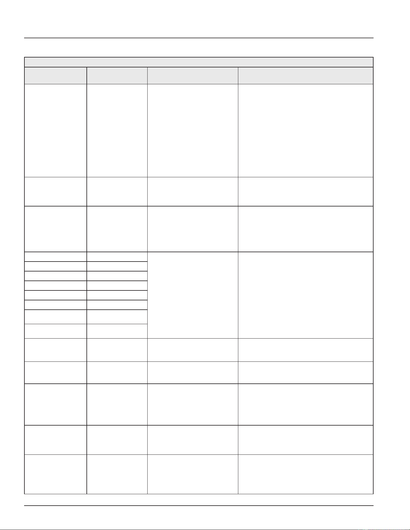
74
Servicing should only be performed by a Qualied Service Technician
ERROR/FAULT CODES
Table 24. Error/Fault Codes
Fault Code Fault Name
Basic Fault Description/Trou-
bleshooting Advanced Fault Explanation/Troubleshooting
007, 00E, 00F,
010, 011, 015,
016, 018, 019,
01A, 01F, 020-023,
028-02B, 02D,030, 031,
033, 036, 037,
039-03C, 043, 044,
04D, 04F, 056,
057, 059-05D, 06C,
06D, 098-09A,
0AF, 0B0, 0B5,
0BB, 0BC, 0C1,
0C3, 0C6, 0C9
0CE, 0CF, 0D1,
0D4, 0D8, 0DA,
0DC, 1AF, 1B0
Hardware Failure Internal control failures have been de-
tected. Cycle power to water heater.
Cycle power to the water heater. If the problem persists,
replace central control board (CCB).
00D AC Wires Reversed The power supply wires have reverse
polarity (black and white wires are
reversed).
The black power supply wire should measure ~ 120V to
ground and the white power supply wire should measure ~0
V to ground. The fault code can also mean poor grounding or
other power supply problems.
031, 032, 033,
034, 035, 036,
037, 038
Power Supply Fail Control has detected a problem with the
power supply.
The control has detected a problem with the incoming power
supply as seen on 24VAC transformer. Error Code 38-2
indicates low supply voltage. Minimum supply voltage is 102
VAC. Error Code 34-1 indicates high supply voltage. Maximum
supply voltage is 132VAC.
045
Upper Temp Probe (Short)
The indicated temperature Probe may be
shorted or open. Check connector and
resistance of Probe.
The indicated temperature probe appears to be shorted (very
low resistance) or is open (very high resistance). This fault
code often means the connector has been corroded by clean-
ing chemicals or other substances.
046 Lower Temp Probe (Short)
047 Upper Temp Probe (Open)
048 Lower Temp Probe (Open)
049 Recirc Temp Probe Short
04A Recirc Temp Probe Open
04B Flue Gas Temp Probe
Short
04C Flue Gas Temp Probe
Open
050 Recirc Temp High Limit The recirculation temperature exceeds
high limit setpoint
The recirculation temperature as measured in the recirculation
loop probe exceeds the temperature high limit. This will auto
clear when temperature drops.
051 Flue Gas Temp High Limit Temperature exceeds ue high limit
setpoint
The temperature as measured in the ue gas probe exceeds
the temperature high limit. This will auto clear when tempera-
ture drops.
057, 058 Flame Sensor (Short) Flame Sensor rod may be grounded or
water present in combustion chamber.
The Flame Sensor rod appears to be grounded (touching
the burner) or water may be present in combustion chamber.
Check for continuity between Flame Sensor and ground
(tank). This fault code can also mean the Flame Sensor is
too close to the burner. If ame sensor is touching the burner,
loosen the screw and adjust the sensor’s position.
054 Temp High Limit The primary temperature exceeds high
limit setpoint
The temperature as measured in the primary probe (upper
if two probes) exceeds the temperature high limit setpoint.
This will auto clear when temperature drops below high limit
setpoint - high limit differential
41B Slave Comm Failure Communication between the CCB and
one or more slave modules has been
lost.
To distinguish which slave module(s) has lost communication
open the electrical cabinet. Each module has a green status
LED. This LED will start to blink rapidly if communication has
been lost.
Cycle the system power, check the communication cables or
replace the module.
Printed on 6/17/2020 12:05 PM CT

75
Servicing should only be performed by a Qualied Service Technician
Table 24. Error/Fault Codes
Fault Code Fault Name
Basic Fault Description/Trou-
bleshooting Advanced Fault Explanation/Troubleshooting
0A5 High Temp Limit Ex-
ceeded
Energy Cut Off has shut off water heater
due to high tank temperature.
The Energy Cut Off (ECO) has shut down the water heater be-
cause very high tank temperatures may have occurred. This is
usually an ECO fault and not an actual high temperature prob-
lem. Check the ECO for proper operation. The ECO is located
in the Upper Temperature Probe. Check the two red wires on
the Upper Temperature Probe (ECO) for continuity. If the tank
temperature is below 160°F (70°) and the ECO is open (high
resistance/no continuity) replace Upper Temperature Probe. If
tank temperature actually reaches/exceeds 201°F, replace the
gas valve and verify correct operation. Heavy scale on Upper
Temperature Probe may sometimes cause this fault code.
0A3 Flue ECO Open Energy Cut Off has shut off water heater
due to high ue temperature.
The Flue Energy Cut Off (ECO) has shut down the water
heater because very high ue temperatures may have oc-
curred. This is usually an ECO fault and not an actual high
temperature problem. Check the ECO for proper operation.
The ECO is located in the Flue Temperature Probe. Check
the two red wires on the Upper Temperature Probe (ECO) for
continuity. If the tank temperature is below 140°F (60°) and
the ECO is open (high resistance/no continuity) replace Upper
Temperature Probe. If ue temperature actually reaches/ex-
ceeds 140°F, replace the gas valve and/or burner may need to
be replaced and verify correct operation.
0A6 Low Gas Pressure Gas pressure is below minimum required
to operate this unit. Check gas pressure
and switch.
The Low Gas Pressure Switch is detecting gas pressure
below the value required for proper operation. Check Low Gas
Pressure Switch wiring and connectors. Connectors must be
clean and tight. Determine proper minimum gas pressure from
data plate. Use manometer or gauge to check gas pressure
during all stages of operation with all other appliances ring.
If pressure falls below data plate requirement, supply pipe
may be too small for application or supply regulator may be
operating improperly. If pressure remains above minimum
requirement, replace Low Gas Pressure Switch.
A07 Blocked Air Intake Restriction in air intake. Check intake
pipe and termination for blockage.
The Blocked Air Intake Switch has detected a possible
restriction in the air intake pipe. Check pipe for restriction or
excessive equivalent length. See Installation Manual for pipe
size, length and maximum number of elbows. Check actual
pipe pressure with a manometer during blower operation. If
air pressure is not below switch activation point but switch is
open, replace switch.
0A8 Blocked Exhaust Restriction in exhaust pipe. Check ex-
haust pipe and termination for blockage.
The Blocked Exhaust Switch has detected a possible
restriction in the exhaust pipe. Check pipe for restriction or
excessive equivalent length. See Installation Manual for pipe
size, length and maximum number of elbows. Check actual
pipe pressure with a manometer during blower operation. If
air pressure is not above switch activation point but switch is
open, replace switch.
0A9 Flame Sensor(error) Flame Sensor rod detected ame when
gas valve should be off. Shut off gas until
repaired.
The Flame Sensor rod has detected ame when the gas valve
is supposed to be off. Look through sight glass. If ame is
present, shut the main gas supply off. If ame is not present,
cycle unit off and on. If fault code returns, replace CCB.
0AC Blower Operation Error Blower Prover Pressure Switch may
have failed closed. Check/replace pres-
sure switch.
The Blower Prover Pressure Switch was detected closed
before blower operation. This switch is normally open and is
used to prove blower operation. This switch should be open
when blower is not running. Check continuity of pressure
switch. If closed, replace switch.
1AD Ext Prv Detect There is a problem with the external
control circuit.
The external control circuit is enabled but open. Verify set-
tings and check the external device.
Printed on 6/17/2020 12:05 PM CT
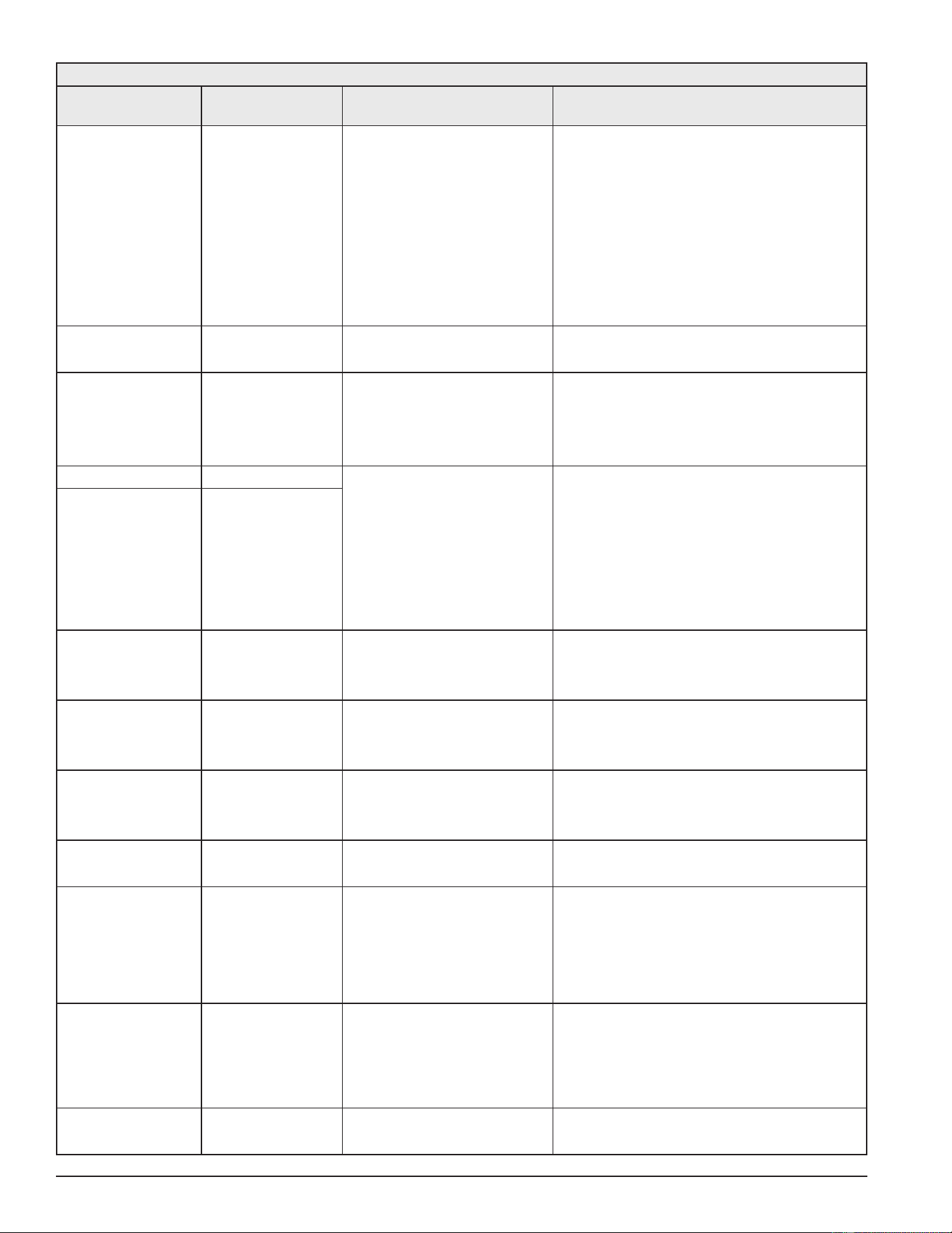
76
Servicing should only be performed by a Qualied Service Technician
Table 24. Error/Fault Codes
Fault Code Fault Name
Basic Fault Description/Trou-
bleshooting Advanced Fault Explanation/Troubleshooting
1AC Blower Prover Open The blower prover switch remains open
after the blower has been energized.
The control has detected an open blower prover pressure
switch during operation.
The blower prover pressure switch will close its contacts on a
pressure rise.
Possible Causes:
1. Blower prover pressure switch sensing tube disconnected
or kinked
2. Loose or open wiring connections to blower prover pressure
switch
3. Blower not running when expected
4. Reduced blower performance
5. Blower prover pressure switch out of calibration (replace
blower prover switch)
0AE Igniter Current Error Igniter current has been detected out of
sequence. Cycle power to water heater.
Cycle power to the water heater. If the problem persists,
replace central control board (CCB).
1AE Low Igniter Current Igniter current is low. The control has detected low current to hot surface igniter.
This fault occurs when igniter current is low.
Possible Causes:
1. Damaged or worn igniter.
2. Loose or open wiring connections to igniter.
0B2 Ignition Failure Flame not detected. Clean ame rod.
Check gas supply.
The control system did not detect ame. Recycle unit off and
on and when gas valve icon appears on display, look through
the sight glass for a brief blue ame. If ame is present, check
ame sense rod. Make sure connector is clean and tight. Re-
move ame rod and clean with steel wool. Check insulator for
soot or damage and replace if necessary. If a brief blue ame
was not seen through the sight glass when the gas valve icon
was displayed, make sure gas valve connections are clean
and tight and gas valve is switched on. Check gas manifold
pressure when gas valve icon appears on display. No ame
usually means a gas supply or gas valve problem. Also check
for restrictions in the heat exchanger. (condensation)
1A9, 0B3 Ignition Failure
0BD Auto Test Complete/
Passed
A ve second dry re auto test cycle is
complete and has passed. This will only
occur on the rst complete heating cycle
Recycle power to resume normal operation.
081 Water Leak Detected A water leak or other water present
condition has been detected. Check for
leak or other water problem at the water
sensor.
Normal operation will continue even though water is detected.
0A4 Condensate Tube Blocked A blockage of the condensate tube has
been detected. Check for blockage and
prober drainage.
Recycle power to resume normal operation.
0BE No Blower Speed Feed-
back
No signal from the blower speed feed-
back sensor was detected.
Check to make sure the sensor is connected correctly connec-
tor pins seated properly.
0D9 Anode Shorted The Powered Anode is shorted to earth
ground or the tank.
The controller has detected a low resistance or short to earth
ground or the tank
Possible Causes:
1. Bent anode shorting to tank or element
2. Contamination (solder, loctite, WD40, Etc.) between anode
top and surrounding metal
3. Power anode shorted to ground at wire connection
0D6 No Water No water detected by Powered Anode. The controller has not detected a voltage potential of water in
the tank
Possible Causes:
1. No water or low water in tank
2. Loose or open wiring connections to power anode(s)
3. Power anode shorted to ground at wire connection
FFFF Undened Fault An unknown fault has been encountered
by the controller.
Cycle power to the water heater. If the problem persists,
replace central control board (CCB) and user interface board
(UIM).
Printed on 6/17/2020 12:05 PM CT
77
Servicing should only be performed by a Qualied Service Technician
Table 24. Error/Fault Codes
Fault Code Fault Name
Basic Fault Description/Trou-
bleshooting Advanced Fault Explanation/Troubleshooting
4F0 UIM External Flash
Memory Fault
The User Interface Module (UIM) has
detected a fault with its external ash
memory.
Reset power to the unit. If this fault prevails the UIM should
be replaced.
4F1 Communication Failure Communications between the user
interface module and the central control
board could not be established. Check
communication cable
Check communication cable between the user interface
module (UIM) and the central control board (CCB). The cable
should be connected to J16 on the CCB.
01C Module disconnected CCB is expecting a module attached to
AIN communications and is not present
Check module power connection. Check for loose connection
or damaged communication cable. Replace module or module
power supply.
074 Flow Switch Stuck Closed Flow switch should be open when heater
is in Standby state. Warning will persist
until detected open in Standby state.
Check for proper installation of ow switch; ow indication
arrow must be pointed upward. Check for shorts in the wiring.
Replace switch if necessary.
175 Flow Not Detected Flow was not detected when in Heating
state
Check for proper installation of ow switch; ow indication ar-
row must be pointed upward. Check the wiring that there are
no loose connections. Check that pump is running in heating
mode, if not check pump wiring and applied 120 VAC in heat-
ing state. Replace if not working.
082 Leak Sensor Discon-
nected
The leak sensor is no longer detected by
the controller.
Ensure connection is good at screw terminals J17 pin3 and 4
are good. Check the sensor and wire for damage or corrosion.
Printed on 6/17/2020 12:05 PM CT

78
Servicing should only be performed by a Qualied Service Technician
NOTES
Printed on 6/17/2020 12:05 PM CT

79
Servicing should only be performed by a Qualied Service Technician
NOTES
Printed on 6/17/2020 12:05 PM CT