MAC 600 (E) NT
user manual

© 2000 Martin Professional A/S, Denmark.
All rights reserved. No part of this manual may be
reproduced, in any form or by any means, without
permission in writing from Martin Professional A/S,
Denmark.
Printed in Denmark.
P/N 35000088 Rev. C

INTRODUCTION . . . . . . . . . . . . . . . . . . . . . . . . . . . . . . . . . . . . . . . . . . . . . . . . . . . . . . . . . . . 4
SAFETY . . . . . . . . . . . . . . . . . . . . . . . . . . . . . . . . . . . . . . . . . . . . . . . . . . . . . . . . . . . . . . . . 5
AC POWER. . . . . . . . . . . . . . . . . . . . . . . . . . . . . . . . . . . . . . . . . . . . . . . . . . . . . . . . . . . . . . 6
LAMP . . . . . . . . . . . . . . . . . . . . . . . . . . . . . . . . . . . . . . . . . . . . . . . . . . . . . . . . . . . . . . . . . . 8
DATA CONNECTION. . . . . . . . . . . . . . . . . . . . . . . . . . . . . . . . . . . . . . . . . . . . . . . . . . . . . . . . 9
RIGGING. . . . . . . . . . . . . . . . . . . . . . . . . . . . . . . . . . . . . . . . . . . . . . . . . . . . . . . . . . . . . . . 10
FIXTURE SETTINGS . . . . . . . . . . . . . . . . . . . . . . . . . . . . . . . . . . . . . . . . . . . . . . . . . . . . . . . 11
OPTICAL CONFIGURATIONS . . . . . . . . . . . . . . . . . . . . . . . . . . . . . . . . . . . . . . . . . . . . . . . . . 18
OPERATION . . . . . . . . . . . . . . . . . . . . . . . . . . . . . . . . . . . . . . . . . . . . . . . . . . . . . . . . . . . . 20
UPDATING SOFTWARE. . . . . . . . . . . . . . . . . . . . . . . . . . . . . . . . . . . . . . . . . . . . . . . . . . . . . 23
FIXTURE SERVICE . . . . . . . . . . . . . . . . . . . . . . . . . . . . . . . . . . . . . . . . . . . . . . . . . . . . . . . . 24
DMX PROTOCOL . . . . . . . . . . . . . . . . . . . . . . . . . . . . . . . . . . . . . . . . . . . . . . . . . . . . . . . . 25
DISPLAY MESSAGES . . . . . . . . . . . . . . . . . . . . . . . . . . . . . . . . . . . . . . . . . . . . . . . . . . . . . . 27
TROUBLESHOOTING . . . . . . . . . . . . . . . . . . . . . . . . . . . . . . . . . . . . . . . . . . . . . . . . . . . . . . 28
CIRCUIT BOARD CONNECTIONS . . . . . . . . . . . . . . . . . . . . . . . . . . . . . . . . . . . . . . . . . . . . . . 29
SPECIFICATIONS . . . . . . . . . . . . . . . . . . . . . . . . . . . . . . . . . . . . . . . . . . . . . . . . . . . . . . . . . 30

4
MAC 600 (E) NT
I
NTRODUCTION
1
The MAC 600 NT is a highly efficient automated 575 watt moving-head wash light that features subtractive cyan,
magenta, and yellow (CMY) color mixing and continuous color temperature correction. It provides a soft-edged 25°
field in the standard configuration. Narrow and wide angle fields may be achieved with accessory snap-lock lens
assemblies.
About this manual
For information about the MAC 600, MAC 600 E, or any other Martin product, please visit the Martin web site at
http://www.martin.dk. The latest updates in fixture software and documentation are available from the Support Area.
Unpacking
The MAC 600 (E) NT comes with
• 2 Fast-Lock Omega clamp brackets
• 5-meter XLR-XLR control cable
• Snoot
• User manual
The packing material is carefully designed to protect the fixture during shipment - always use it or a suitable flight case
to transport the fixture.

Safety
5
S
AFETY
2
Warning! This product is for professional use only. It is not for household use.
This product presents risks of lethal or severe injury due to fire and heat, electric shock, ultraviolet radiation, lamp
explosion, and falls. Read this manual before powering or installing the fixture, follow the safety precautions listed
below and observe all warnings in this manual and printed on the fixture. If you have questions about how to operate
the fixture safely, please contact your Martin dealer or call the Martin 24-hour service hotline at +45 70 200 201.
TO PROTECT YOURSELF AND OTHERS FROM ELECTRIC SHOCK
• Disconnect the fixture from AC power before removing or installing the lamp, fuses, or any part, and when not in use.
• Always ground (earth) the fixture electrically.
• Use only a source of AC power that complies with local building and electrical codes and has both overload and
ground-fault protection.
• Do not expose the fixture to rain or moisture.
• Refer any service operation not described in this manual to a qualified technician.
TO PROTECT YOURSELF AND OTHERS FROM UV RADIATION AND
LAMP EXPLOSION
• Never operate the fixture with missing or damaged lenses and/or covers.
• When replacing the lamp, allow the fixture to cool for at least 15 minutes before opening the fixture or removing the
lamp. Protect your hands and eyes with gloves and safety glasses.
• Do not stare directly into the light. Never look at an exposed lamp while it is lit.
• Replace the lamp before usage exceeds the maximum service life, or if the lamp is defective or worn out.
TO PROTECT YOURSELF AND OTHERS FROM BURNS AND FIRE
• Never bypass the fuses. Always replace defective fuses with ones of the specified type and rating.
• Keep all combustible materials (for example fabric, wood, paper) at least 1.0 meter (39 inches) away from the fixture.
Keep flammable materials well away from the fixture.
• Do not illuminate surfaces within 1.0 meter (39 inches) of the fixture.
• Provide a minimum clearance of 0.1 meters (4 inches) around fans and air vents.
• Never place filters or other materials over the lens.
• Allow the fixture to cool for at least 5 minutes before handling.
• Do not modify the fixture or install other than genuine Martin parts.
• Do not operate the fixture if the ambient temperature (Ta) exceeds 40° C (104° F).
TO PROTECT YOURSELF AND OTHERS FROM INJURY DUE TO FALLS
• When suspending the fixture, verify that the structure can hold at least 10 times the weight of all installed devices.
• Verify that all external covers and rigging hardware are securely fastened and use an approved means of secondary
attachment such as a safety cable.
• Block access below the work area whenever installing or removing the fixture.
• Do not lift the fixture by its head.

6
MAC 600 (E) NT
AC
POWER
3
WARNING! For protection from dangerous electric shock, the fixture must be grounded (earthed). The
AC mains supply shall be fitted with a fuse or circuit breaker and ground-fault protection.
Important! Verify that the power supply settings match the mains voltage before applying power.
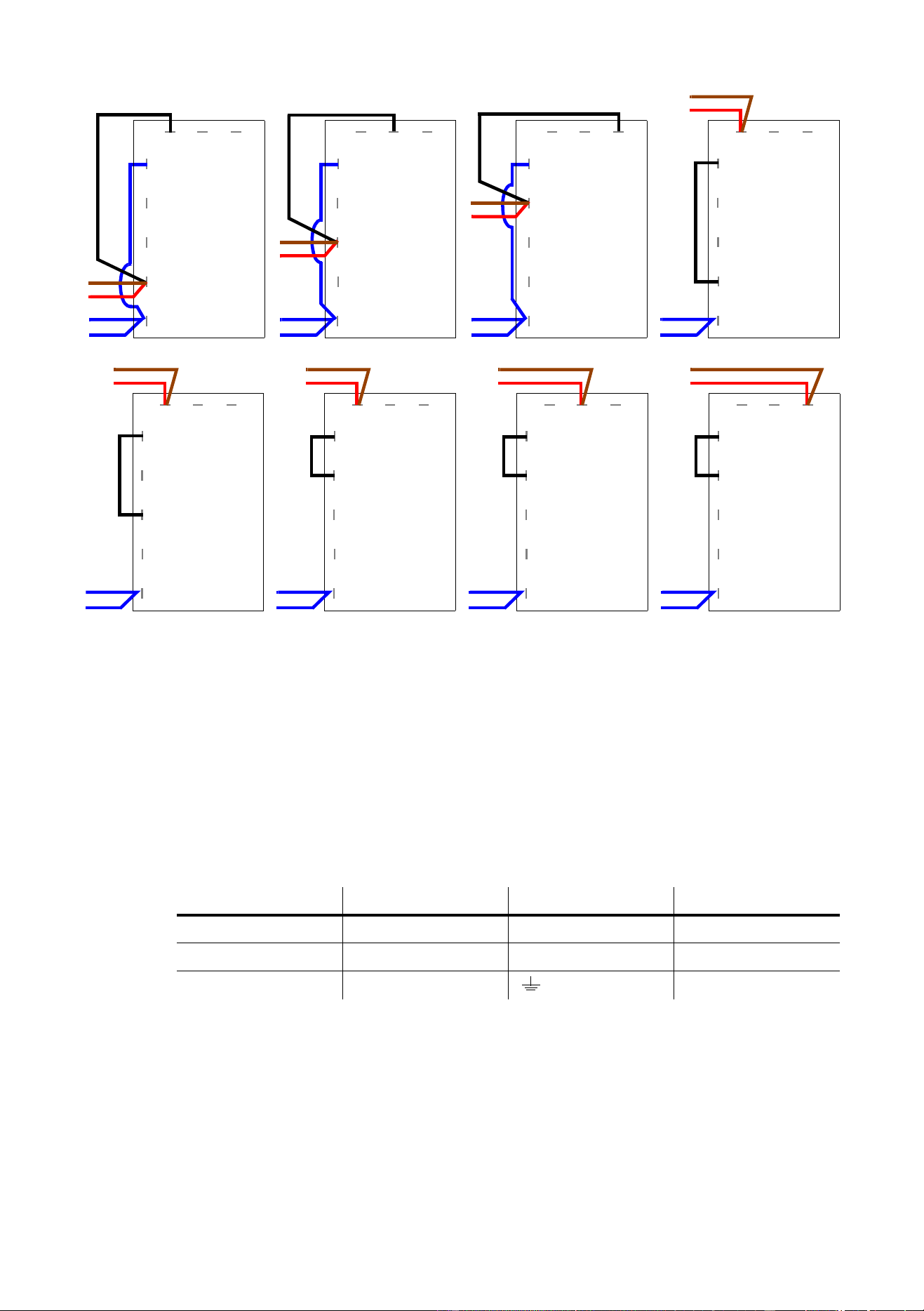
Power supply settings
The MAC 600 (E) NT must be tapped correctly for the local AC voltage and frequency. The wrong setting can cause
overheating, damage, and poor performance. The factory settings are printed on the label under the base. The
procedure for changing the power supply settings depends on the model.
To change the MAC 600 NT power supply settings
1
Disconnect the fixture from AC power.
Remove the top covers.
2 Find the correct transformer and ballast terminals for your AC supply in the table below.
3 Locate the transformer: it is on the left end, near the power switch. Move the BROWN and RED transformer
wires to the correct terminal. The terminal number is printed in front of the connection tab.
4 Locate the ballast: it is on the opposite end from the transformer, near the control panel. Move the BROWN
ballast wire to the correct terminal. The terminal number is printed in front of the connection tab.
5 Replace the covers before applying power.
To change the MAC 600 E NT power supply settings
The MAC 600 E NT electronic ballast is auto-ranging and works at any voltage between 100 and 250 volts and at any
frequency between 50 and 60 Hz. Simply tap the transformer for the local AC voltage as shown below. When
switching to or from the 100 - 120 V settings, the primary fuse must be changed as well.
1
Disconnect the fixture from AC power.
Remove the top covers.
2 Tap the
transformer
for the local supply voltage as shown below.
3 Verify that the primary fuse, which is located near the power switch, is correct for the voltage setting. The
fuse shall be a T 6.3 A fuse when the transformer is set at 200, 210, 220, 230, or 240 V. It shall be a T 10 A
fuse when set at 100, 110, or 120 V.
4 Replace the top covers before applying power.
AC Supply Transformer Ballast
Frequency Voltage Voltage Terminal Setting Terminal
50 Hz 200-210 V 210 V 4 200 V / 50 Hz 7
50 Hz 210-220 V 210 V 4 230 V / 50 Hz 10
50 Hz 220-235 V 230 V 6 230 V / 50 Hz 10
50 Hz 235-240 V 230 V 6 245 V / 50 Hz 12
50 Hz 240-260 V 250 V 8 245 V / 50 Hz 12
60 HZ 200-217 V 210 V 4 208 V / 60 Hz 4
60 HZ 217-240 V 230 V 6 227 V / 60 Hz 7
AC power
7
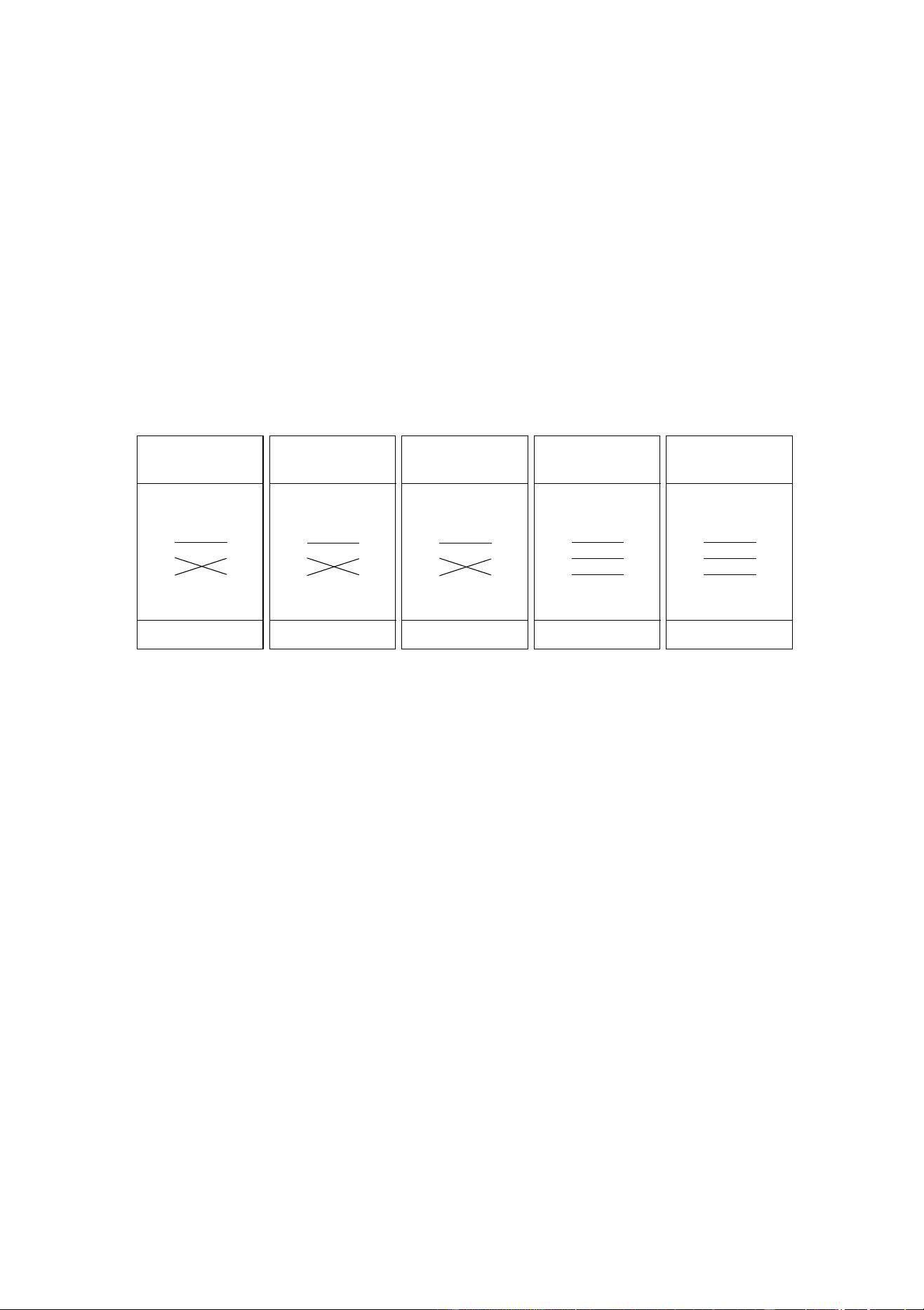
Power connection
You may need to install a cord cap that fits your supply on the power cable. A 3-prong grounding-type plug must be
installed following the manufacturer’s instructions. The table shows some possible pin identification schemes; if the
pins are not clearly identified, or if you have any doubts about proper installation, consult a qualified electrician.
Connect the MAC 600 (E) NT directly to AC power. Do not connect it to a dimmer system; doing so may damage the
fixture.
To apply power, set the power switch on the base to the “I” position.
Wire Color Pin Symbol Screw (US)
brown live L yellow or brass
blue neutral N silver
yellow/green ground green
1
4
5
7 8 9
black
blue
blue
110 V
3
red
brown
6
blue
1
3
4
5
6
7 8 9
brown
red
black
blue
blue
220 V
1
3
4
5
6
7 8 9
brown
red
black
blue
blue
230 V
1
3
4
5
6
7 8 9
brown
red
black
blue
blue
240 V
1
4
5
7 8 9
black
blue
blue
100 V
3
red
brown
6
blue
1
4
5
7 8 9
black
blue
blue
120 V
3
red
brown
6
blue
MAC 600 NT E
Transformer
Settings
1
3
4
5
6
7 8 9
brown
red
black
blue
blue
200 V
1
3
4
5
6
7 8 9
brown
red
black
blue
blue
210 V

8
MAC 600 (E) NT
L
AMP
4
Compatible lamps
The MAC 600 (E) NT shall be used only with the lamps listed on page 30. Installing any other lamp may damage the
fixture or create a safety hazard.
Maximum usable hours
The risk of lamp explosion increases with usage due to gradual weakening of the quartz envelope. To minimize the risk
of lamp explosion, replace lamps before usage exceeds the rated life by 200 hours or the manufacturer’s stated
maximum service life.
To track usage, reset the
RLAH and RLST counters under the TIME menu when installing a new lamp. See
page 14.
Installation and alignment
WARNING! Disconnect the fixture from AC power before proceeding. Always wear safety goggles to
protect your eyes and allow a hot lamp to cool for at least 15 minutes before removing it
from the fixture.
To install a lamp
1 Remove the 2 thumbscrews securing the lamp-socket assembly to the rear of the head. Pull out the lamp-
socket assembly and remove the old lamp from the socket.
2 Holding the new lamp by its ceramic base (do not touch the glass), insert it fully into the lamp socket.
3 Clean the glass bulb with the cloth supplied with the lamp, particularly if you touched the glass. A clean, lint-
free cloth wetted with alcohol may also be used.
4 Keep the lamp wire between the fins as you insert the lamp-socket assembly into the head. Turn the
assembly counterclockwise to align the holes with the spacer nuts. Replace the thumbscrews and tighten
them by hand.
5 See page 14 to reset the lamp hour (
RLAH) and lamp strike (RLST) counters.
To align a lamp
Align the lamp if light distribution is uneven.
1 Switch on the MAC 600 (E) NT and allow it to reset.
2 Using either a controller or the control module, turn on the lamp and project the light on a flat surface.
3 Center the hot-spot (the brightest part of the beam) using the 3 Allen-head (3 mm) adjustment screws. Turn
one screw at a time to drag the hot-spot diagonally across the field. If you cannot detect a hot-spot, adjust
the lamp until the light is even.
4 To reduce the hot-spot, pull the lamp in by turning all three screws clockwise 1/4-turn at a time until the light
is evenly distributed.
5 If the light is brighter around the edge than it is in the center, or if light output is low, the lamp is too far back
in the reflector. “Push” the lamp out by turning the screws counterclockwise 1/4-turn at a time until the light
is bright and evenly distributed.
Data connection
9
D
ATA
CONNECTION
5
The MAC 600 (E) NT has locking 3-pin data input and output sockets that are compatible with DMX 512 devices, i.e.,
pin 1 to shield, pin 2 to cold (-) and pin 3 to hot (+). If required, the polarity of pins 2 and 3 can be reversed for
compatibility with earlier Martin fixtures.
Connecting fixtures
ADAPTOR CABLES
The following adaptor cables are available for connection to devices with different sockets.
To connect the data link
1 Connect the controller’s DMX data output to the MAC 600 (E) NT’s data input with a cable such as the one
supplied. Insert a 5-pin to 3-pin adaptor if the controller output has 5 pins. (Pins 4 and 5 are not used.)
2 To continue the link, connect the output of the fixture closest to the controller to the input of the next fixture.
Note: Martin fixtures introduced before 1997 have reversed polarity data sockets, i.e., pin 2 hot (+) and pin 3 cold (-).
The socket polarity is labelled. Use a phase-reversing cable between the MAC 600 (E) NT (or other DMX-compatible
device) and any Martin device with reversed polarity.
3 Insert a male 120
Ω
XLR termination plug in the output of the last fixture on the link.
TIPS FOR BUILDING A DATA LINK
• Use shielded twisted-pair cable designed for RS-485 devices: standard microphone cable cannot transmit
control data reliably over long runs. 24 AWG cable is suitable for runs up to 300 meters (1000 ft). Heavier
gauge cable and/or an amplifier is recommended for longer runs.
• Never use a “Y” connector to split the link. To split the serial link into branches use a splitter such as the
Martin 4-Channel Opto-Isolated RS-485 Splitter/Amplifier.
• Do not overload the link. Up to 32 devices may be connected on a serial link.
• Terminate the link by installing a termination plug in the output socket of the last fixture. The termination
plug, which is a male XLR plug with a 120 ohm, 0.25 watt resistor soldered between pins 2 and 3, “soaks
up” the control signal so it does not reflect and cause interference. If a splitter is used, terminate each
branch of the link.
Phase-Reversing
Cable
Male Female
1
2
3
1
2
3
3-pin to 3-pin
Connections
P/N 11820006
Phase-Reversing
Cable
Male Female
1
2
3
1
2
3
4
5
3-pin to 5-pin
Connections
P/N 11820002
Phase-Reversing
Cable
Male Female
1
2
3
4
5
1
2
3
5-pin to 3-pin
Connections
P/N 11820003
Straight
Cable
Male Female
1
2
3
4
5
1
2
3
5-pin to 3-pin
Connections
P/N 11820005
Straight
Cable
Male Female
1
2
3
1
2
3
4
5
3-pin to 5-pin
Connections
P/N 11820004
10
MAC 600 (E) NT
R
IGGING
6
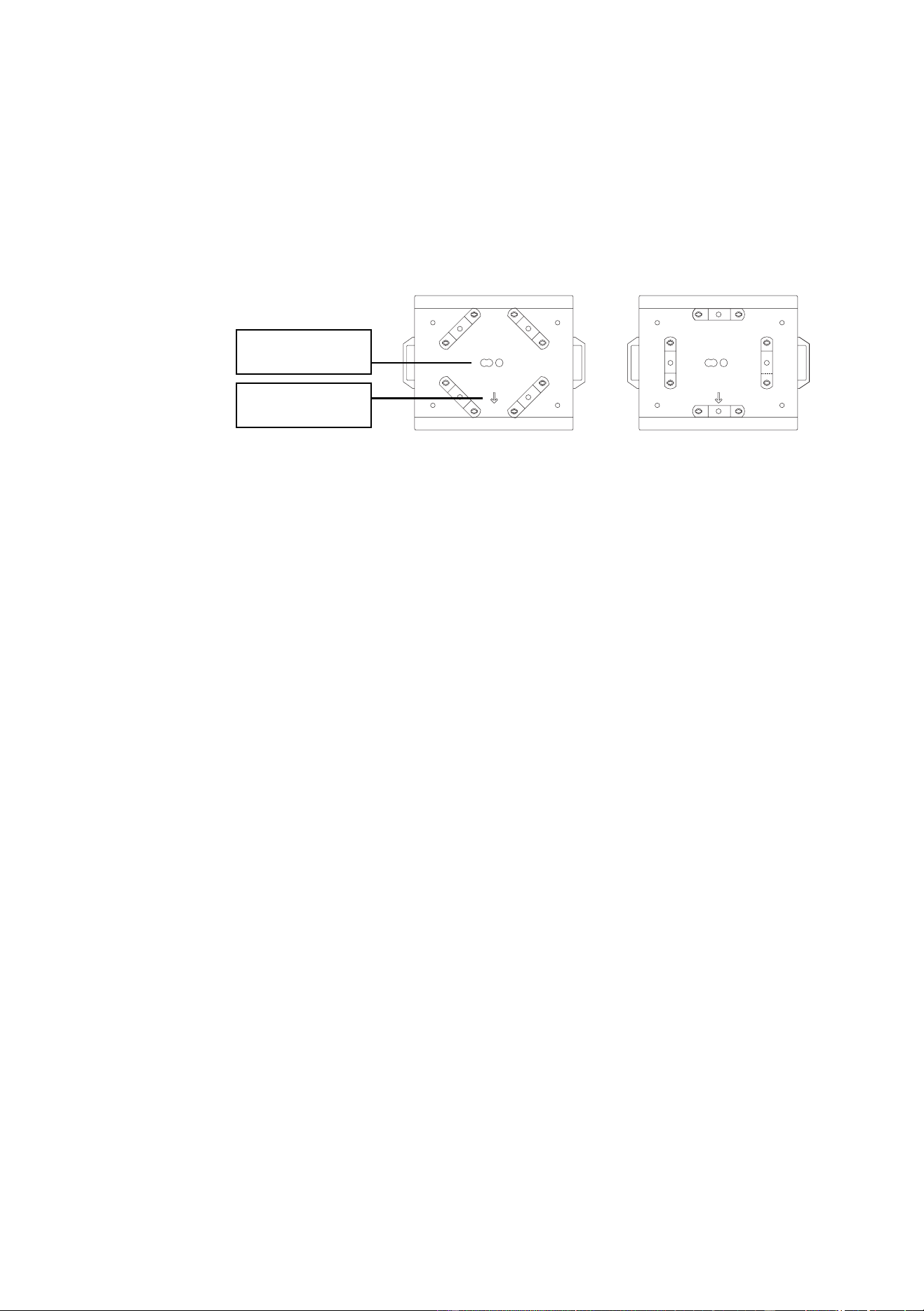
The MAC 600 (E) NT can be placed directly on the stage floor or rigged in any orientation on a truss. The integrated
Fast-Lock system enables quick and easy fastening of the clamp adapters in 4 different positions as shown below.
The front of the fixture, which is defined as the middle of the pan range, is indicated by an arrow on the base.
Warning! Always use 2 clamps to rig the fixture. Lock each clamp with both 1/4-turn fasteners. The
fasteners are locked only when turned fully clockwise.
Warning! Attach an approved safety cable to the base.
To hang the fixture on a truss
1 Verify that the rigging clamps (not included) are undamaged and can bear at least 10 times the weight of the
fixture. Verify that the structure can bear at least 10 times the weight of all installed fixtures, clamps, cables,
auxiliary equipment, etc.
2 Bolt each clamp securely to a clamp bracket with an M12 bolt (grade 8.8 or better) and lock nut.
3 Align a clamp with 2 mounting points in the base. Insert the fasteners into the base and turn both levers a
full 1/4-turn clockwise to lock. Install the second clamp.
4 Block access under the work area. Working safely from a stable platform, hang the fixture on the truss with
the arrow towards the area to be illuminated. Tighten the rigging clamps.
5 Install a safety wire that can bear at least 10 times the weight of the fixture. The attachment point is
designed to fit a caribiner clamp.
Never use the carrying handles for secondary attachment.
6 Verify that there are no combustible materials or surfaces to be illuminated within 1 meter of the fixture, and
that there are no flammable materials nearby.
safety wire
attachment point
arrow points to front
(neutral pan)
Fixture settings
11
F
IXTURE
SETTINGS
7
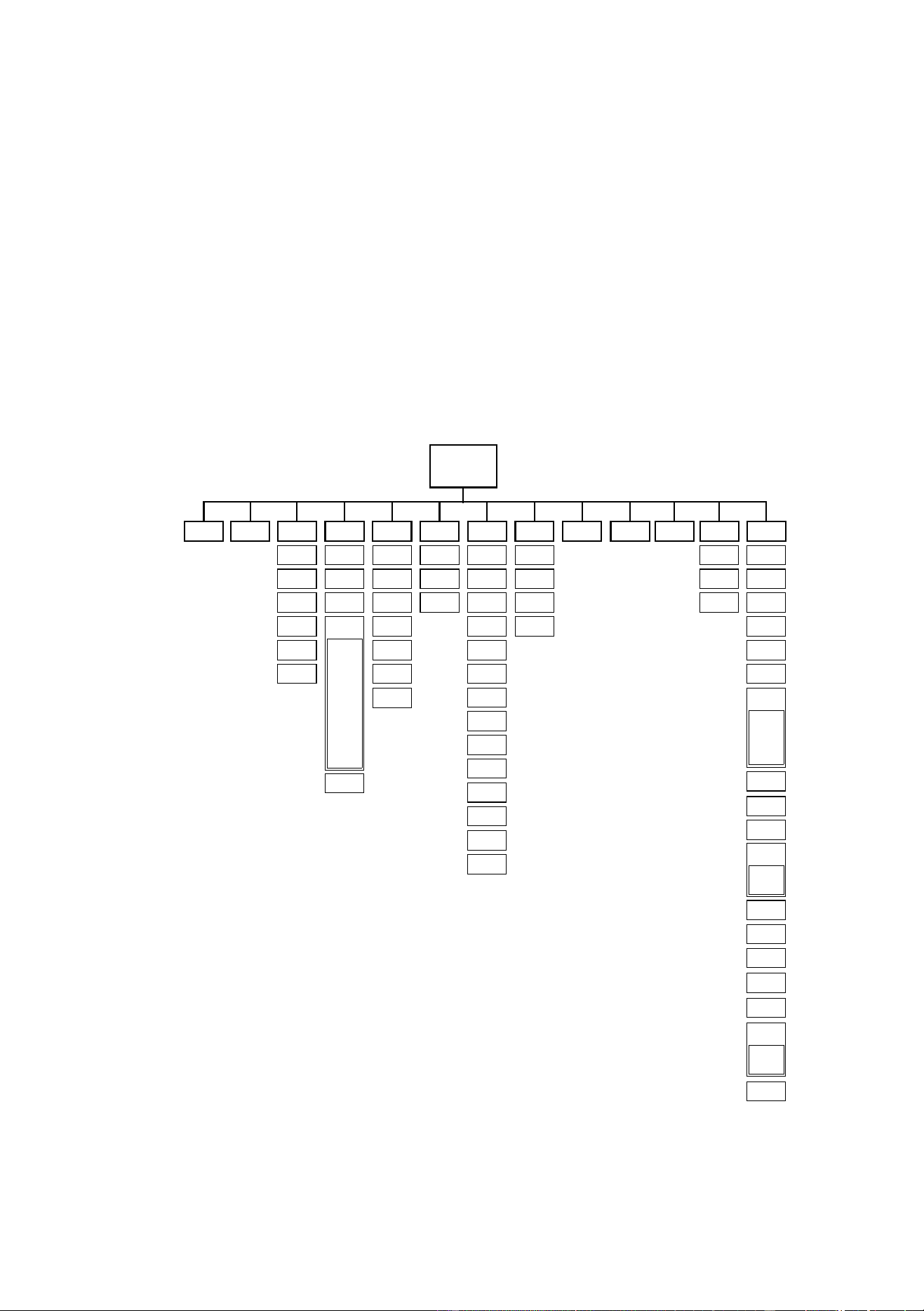
The LED control panel is used to set the address and personalities, read lamp hours and other information, calibrate
effects, control the fixture manually, and run a test routine. Most of these functions may be performed remotely via the
serial link with the MPBB1 Uploader.
Menu navigation
The display can be flipped for easy reading by pressing the [↑] and [↓] keys simultaneously. The intensity is adjustable
and the display can be set to go out 2 minutes after the last key-press. See “Personality settings” on page 13.
The DMX address and any messages are displayed when the MAC 600 (E) NT is turned on. To enter the menu, press
[MENU]. Use the [↑] and [↓] keys to move within the menu. To select a function or submenu, press [ENTER]. To
escape a function or menu, press [MENU].
dAdr
TIME
AdJ CAL PATI VER
PSET
MAN dMXL PTSP SPEC
Address/
Messages
Po H
RPoH
LA H
RLAH
LSTR
RLST
RST
L ON
LoFF
HEAd
PATI
T OF
d OF
C OF
M OF
P OF SWAP
PINV
TINV
RST
L ON
SHUT
dIM
CYAN
MAG
LoFF
YEL
CTC
FROS
PAN
TILT
BS
STCO
CH 0
....
CH14
CPU
FEbA
dISP
dISP
dLOF
dRES
ALON
dINT
dFOF
UPLd
PCbT
SCUT
ASHT
FAN
FTST
ALL
dIM
CYAN
MAG
YEL
COL
BS
FROS
dFSE
FACT
CUS1
CUS2
CUS3
TEMP
bASE
HEAd
TSEQ
EFFb
MOdE
SHUT
Y OF FEbA
TRAC
MOdE
CAL
CTC
CTOF
COL
CMYS
ETYP

12
MAC 600 (E) NT
DMX mode and address
The DMX mode options are described under “DMX-512 control” on page 20. Maximum flexibility is provided in
mode 4.
The address, also known as the start channel, is the first channel used to receive instructions from the controller. For
independent control, each fixture must be assigned its own control channels. Two MAC 600 (E) NTs may share the
same address, however, if identical behavior is desired. Address sharing can be useful for diagnostic purposes and
other situations, particularly when combined with the inverse pan and tilt options.
To set DMX mode and address
1 Switch on the fixture.
2 If the fixture is in a flight case, press [MENU] and [ENTER] at the same time to disable pan and tilt reset. (A
partial reset can take 2 - 3 minutes and error messages will be displayed.)
3 Press [MENU] once to enter the main menu.
4Select
PSET and press [ENTER]. Scroll to the desired DMX mode (1, 2, 3, or 4) and press [ENTER].
5Select dAdr from the main menu and press [ENTER]. Scroll to the desired DMX address and press
[ENTER].
Fixture settings
13
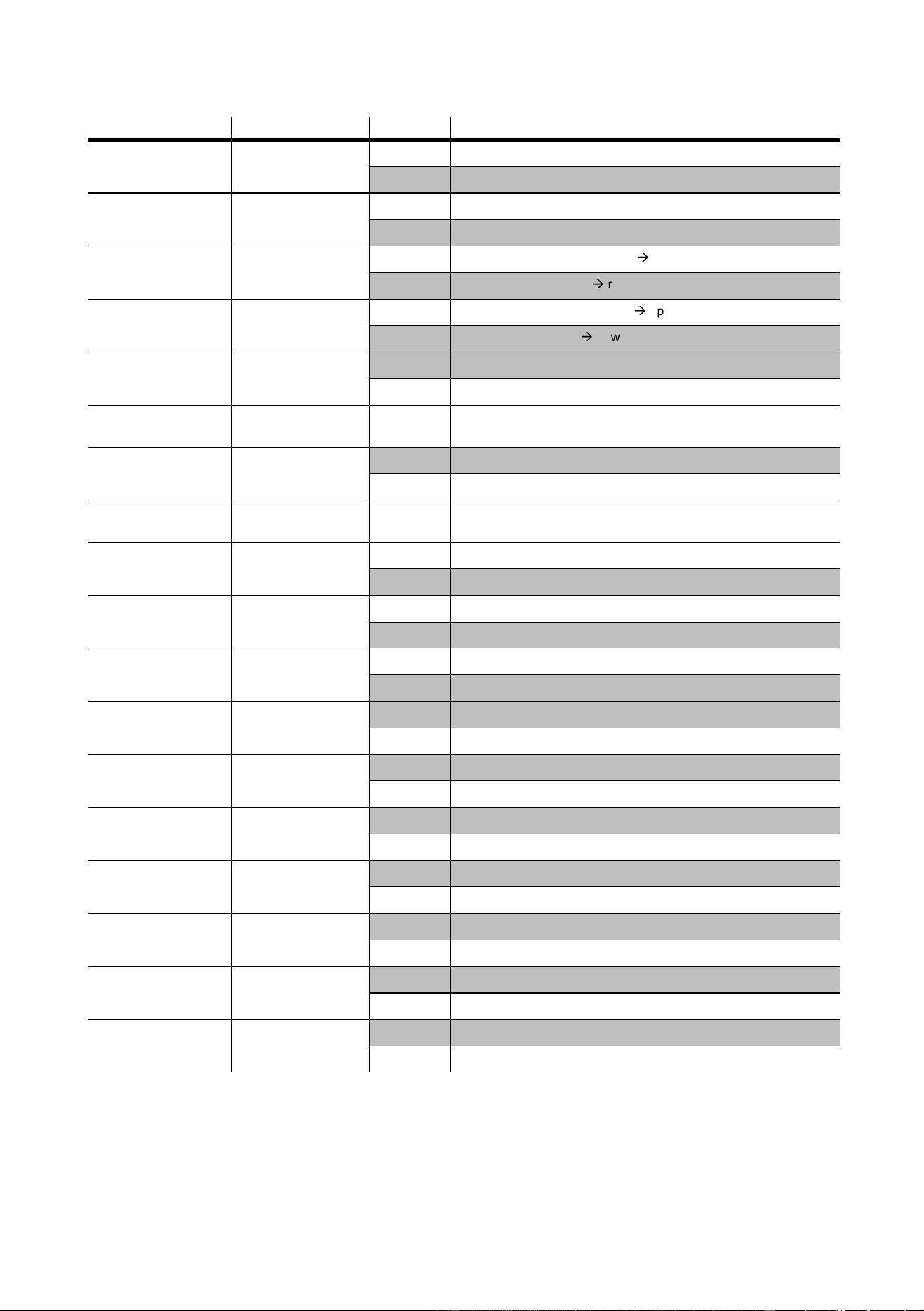
Personality settings
* Setting may be overridden via DMX. See the protocol for details.
Personality Path Options Effect (Default settings shaded.)
Pan/tilt speed
PTSP
FAST
Optimize movement for speed.*
NORM
Optimize movement for smoothness.*
Pan/tilt swap
PATI/SWAP
ON
Map DMX pan control to tilt channel and vice versa.
OFF
Normal pan and tilt control.
Pan inverse
PATI/PINV
ON
Reverse DMX pan control, right
Æ
left.
OFF
Normal pan control, left
Æ
right.
Tilt inverse
PATI/TINV
ON
Reverse DMX tilt control, down
Æ
up.
OFF
Normal tilt control, up
Æ
down
Tracking algorithm
SPEC/TRAC/
MOdE
MOd1
Absolute delta value algorithm (for most controllers)
MOd2
Real delta value algorithm
Tracking samples
SPEC/TRAC/
CAL
1-10
Tracking samples. Increase if pan/tilt is not smooth.
Display on/off
SPEC/dISP
ON
Display stays on.
OFF
Display goes out 2 minutes after last key press.
Display intensity
SPEC/dINT
10-
100
Adjust display intensity.
DMX lamp off
SPEC/dLOF
ON
Enable DMX lamp off command.
OFF
Disable DMX lamp off command.*
DMX reset
SPEC/dRES
ON
Enable DMX reset command.
OFF
Disable DMX reset command.*
Automatic lamp on
SPEC/ALON
ON
Lamp strikes automatically within 90 seconds of power on.
OFF
Strike lamp from controller.
Shortcuts
SPEC/SCUT
ON
Dimmer, color wheel, and beam shaper take shortest path.*
OFF
Dimmer, color wheel, and beam shaper paths oscillate.*
Automatic shutter
SPEC/ASHT
ON
Enable fast (shutter) blackout on dimmer channel.
OFF
Shutter not activated by dimmer channel.
Studio mode
MOdE
NORM
Optimize effects for speed.*
STUd
Optimize effects for silence.*
Pan/tilt feedback
SPEC/FEbA
ON
Enable pan/tilt position correction system.
OFF
Disable pan/tilt feedback. Setting not saved.
Effects feedback
SPEC/EFFb
ON
Enable on the fly reset of dimmer, color wheel, and beam shaper.
OFF
Disable on the fly reset of dimmer, color wheel, and beam shaper.
Fan speed
SPEC/FAN
REG
Enable automatic fan speed regulation.
FULL
Set fan speed to full.
CMY speed
SPEC/CMYS
FULL
Optimize color mixing for speed.
REdU
Optimize color mixing for quietness.
14
MAC 600 (E) NT
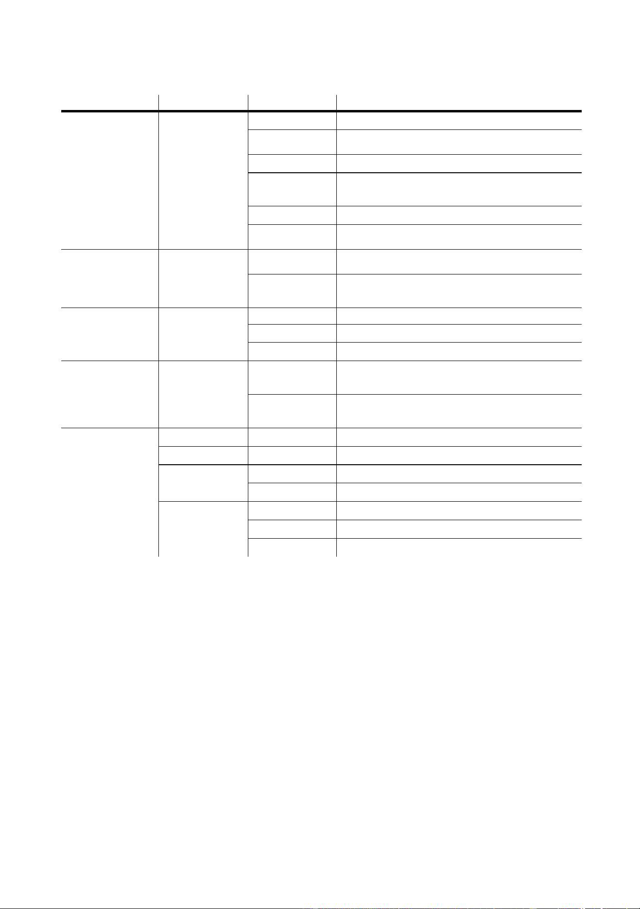
Tests and readouts
The following readouts and tests are available from the control panel.
To calibrate temperature sensors
The temperature sensors are calibrated at the factory. Use this procedure if you suspect the calibration is faulty.
1 Turn off the fixture for 4 hours to allow it to cool to room temperature.
2 Measure the room temperature in Celsius. (To convert F° to C°, subtract 32° and multiply by 0.555.)
3 Power up the unit and allow it to reset.
4 Press [MENU] and [↓] and hold until “25” is displayed.
5 Scroll to the room temperature and press [ENTER].
Function Path Options Readout or effect
Usage counters
TIME/
Po H
Total hours of operation since fabricated.
RPoH
Hours of operation since counter reset. To reset, display
counter and press [↑
]
for 5 seconds.
LA H
Total hours of operation with lamp on since fabricated.
RLAH
Lamp hours since counter reset. Reset when relamping to
track lamp life. To reset, display counter and press [↑
]
for 5
seconds.
LSTR
Total number of lamp strikes since fabricated.
RSTR Number of lamp strikes since counter reset. To reset, display
counter and press [↑
]
for 5 seconds.
DMX readout
dMXL/
STCO
Decimal value of the DMX start code. The start code must be
0 for the MAC 600 (E) NT to function properly.
CH 0..CH14
DMX value (from 0 - 255) received for each channel. Note
that the channel number is 1 less than it is in the DMX
protocol.
Software versions
Ver/
CPU
CPU firmware version. Updates can be uploaded.
FEBA
Feedback circuit firmware version.
dISP
Display circuit firmware version.
Temperature readout
SPEC/TEMP/
HEAd
Head temperature in Celsius. Temperatures below 25° C are
shown as
-25; temperatures above 100° C are shown as
+100.
bASE
Base temperature in Celsius. Temperatures below 25° C are
shown as
-25; temperatures above 100° C are shown as
+100.
Tests
TSEQ RUN
Run a general test of all effects
SPEC/PCbT T1-T3
Run three tests of the circuit board.
For service use only.
SPEC/FTST/
WTST
Run an quality control effects test
MTST
Run a quality control movement test
SPEC/FTST/
STST
dIM
Run a quality control dimmer sensor test
COL
Run a quality control color wheel sensor test
bS
Run a quality control beam shaper sensor test

Fixture settings
15
Manual control
The manual control menu provides limited operation from the control panel.
Function Path Options Effect
Reset
MAN/ RST
Reset fixture
Lamp on
MAN/ L ON
Strike lamp
Lamp off
MAN/ LoFF
Douse lamp
Shutter
MAN/SHUT
Open
Open shutter
CLOS Close shutter
STRF Strobe, fast
STRM Strobe, medium
STRS Strobe, slow
Dimmer
MAN/dIM
0-255
Insert dimmer wheel
Cyan
MAN/CYAN
0-255
Insert the cyan flags
Magenta
MAN/MAG
0-255
Insert the magenta flags
Yellow
MAN/YEL
0-255
Insert the yellow flags
Color correction
MAN/CTC
0-255
Insert the color temperature correction flags
Fixed color
MAN/COL
Open
Set color wheel to open position
COL1-
COL4
Set color wheel to position 1-4
Beam shaper
MAN/bS
0-255
Insert the beam shaper
Frost
MAN/FROS
0-255
Insert the frost filter
Pan
MAN/PAN
0-255
Pan the head
Tilt
MAN/TILT
0-255
Tilt the head
16
MAC 600 (E) NT
Adjustment control
The adjustment menu provides manual control for making mechanical adjustments. These shall be performed by a
qualified technician.
Function Path Options Effect
Reset
AdJ/ RST
Reset fixture
Lamp on
AdJ/ L ON
Strike lamp
Lamp off
AdJ/ LoFF
Douse lamp
Adjust all
AdJ/HEAd/
ALL
Open
Set all effects in the head to the full open position
CLOS
Set all effects in the head to the full closed position
SPOS
Set magnetically-indexed effects to the sensor position
Adjust dimmer
AdJ/HEAd/
DIM
OPEN
Set dimmer to open position
CLOS
Set dimmer to closed position
SPOS
Set dimmer to indexing (sensor) position
Adjust cyan
AdJ/HEAd/
CYAN
OPEN
Set cyan to open position
CLOS
Set cyan to closed position
Adjust magenta
AdJ/HEAd/
MAG
OPEN
Set magenta to open position
CLOS
Set magenta to closed position
Adjust yellow
AdJ/HEAd/
YEL
OPEN
Set yellow to open position
CLOS
Set yellow to closed position
Adjust CTC
AdJ/HEAd/
CTC
OPEN
Set CTC to open position
CLOS
Set CTC to closed position
Adjust color wheel
AdJ/HEAd/
COL
OPEN
Set color wheel to open position
CLOS
Set color wheel to closed position
SPOS
Set color wheel to indexing (sensor) position
Adjust beam shaper
AdJ/HEAd/
bS
OPEN
Set beam shaper to open position
CLOS
Set beam shaper to closed position
SPOS
Set beam shaper to indexing (sensor) position
Adjust frost
AdJ/HEAd/
FROS
OPEN
Set frost to open position
CLOS
Set frost to closed position
Adjust shutter
AdJ/HEAd/
SHUT
OPEN
Open shutter
CLOS
Close shutter
Adjust pan/tilt
AdJ/PATI NEUT
Set pan and tilt to neutral positions
PNTd-
PRTU
Move pan and tilt to limits
Fixture settings
17
Utilities
CALIBRATION
The calibration function allows you to fine-tune effect positions for uniformity between fixtures. Using one fixture as a
reference, adjust the offsets of the other fixtures to match the reference.
CUSTOM CONFIGURATIONS
The custom configuration function allows you to save and recall three sets of fixture settings. The savable settings are
DMX mode, pan/tilt speed, pan/tilt inverse and swap, CMY speed, DMX lamp off and reset, display settings,
automatic shutter, shortcuts, studio mode, fan speed, automatic lamp on, effects feedback, tracking algorithm, and
tracking samples.
UPLOAD SOFTWARE
The software update mode is normally engaged automatically by the upload device. See “Updating software” on
page 23.
Function Path Options Effect
Calibration
CAL
P OF
Adjust pan offset
T OF
Adjust tilt offset
d OF
Adjust dimmer offset
C OF
Adjust cyan offset
M OF
Adjust magenta offset
Y OF
Adjust yellow offset
CTOF
Adjust CTC offset
Default offsets
SPEC/dFOF SURE
Reset all effects to the default offset setting
Custom configuration
SPEC/dFSE/
CUS1,
CUS2,
CUS3
LOAd
Load custom configuration 1-3.
SAVE
Save custom configuration 1-3. Adjust settings as desired before
selecting. Press [ENTER] to save.
Default configuration
SPEC/dFSE/
FACT
LOAD
Return all personality settings (not calibrations) to factory defaults.
Upload software
SPEC/UPLD SURE
Manually set fixture to software update mode.
18
MAC 600 (E) NT
O
PTICAL
CONFIGURATIONS
8
Field angles
Narrow and wide angle options are available for the MAC 600 (E) NT. The optional lenses are mounted in snap-lock
hoods for easy changing. See “Accessories” on page 31.
Note: The narrow angle hood is longer than the standard hood. Because of this, MAC 600s and MAC 600 (E) NTs
fitted with the narrow angle hood fit only in flight cases produced after September, 1997. These measure 894 mm
(35.2") from bottom to top, including wheels. Earlier flight cases measure 860 mm (34") from bottom to top, including
wheels.
To change field angle
1 Release the snap locks and remove the hood and lens assembly.
2 Unhook the head safety wire from the hood being removed and place it on the one being installed.
3 Place the hood over the head. Align and close the snap locks.
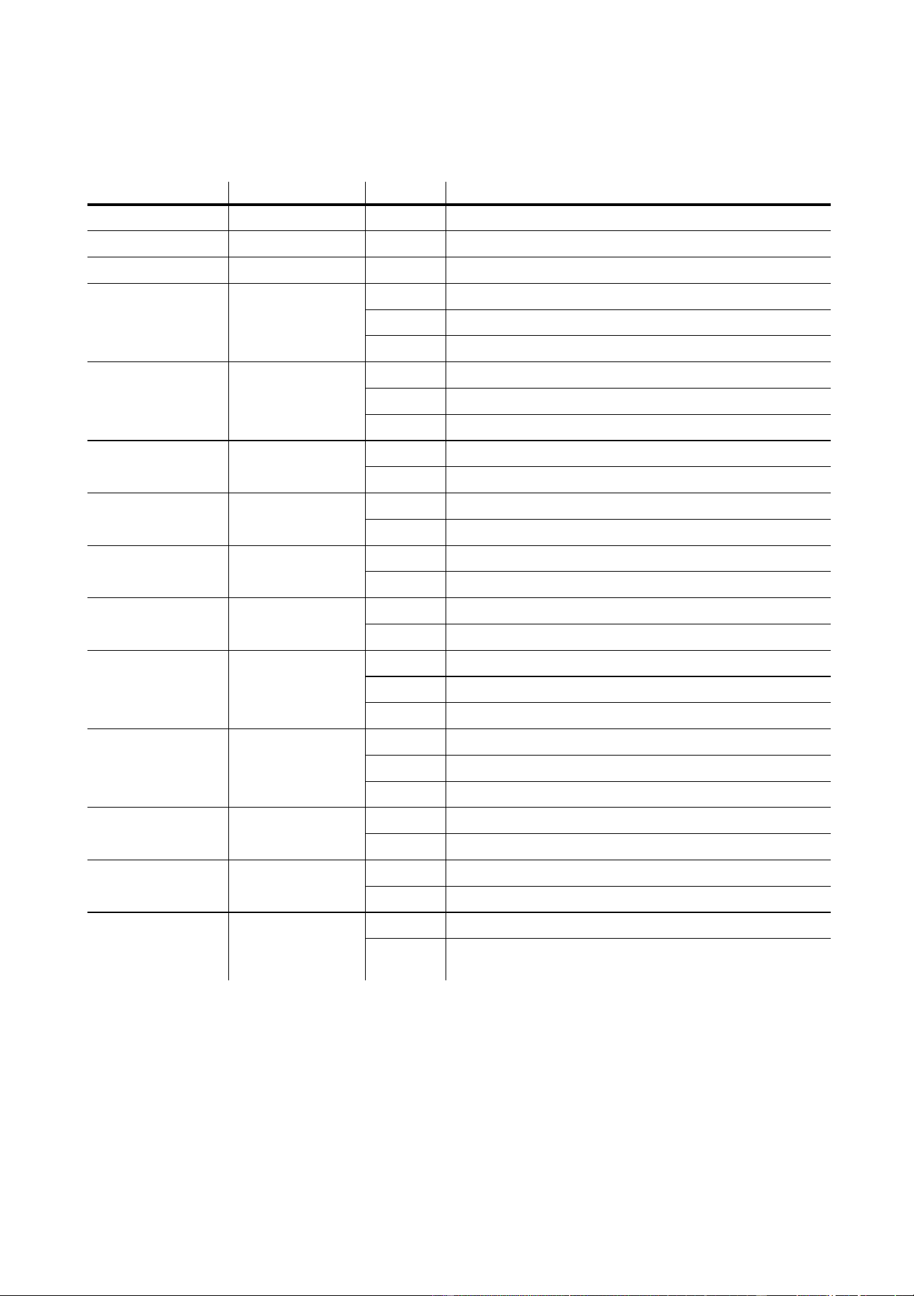
Color filters
The color wheel provides 4 dichroic glass filters: red 308, green 203, blue 108 and UV. The filters are held by a spring
clip and may be removed. To avoid damaging the coating, wear clean lint-free gloves when handling the filters.
To remove and install a color filter
1 Disconnect the fixture from AC power and allow it to cool. Unlatch and remove the front head section.
2 Turn the desired filter position to the access cut-out.
3 To remove a filter, tilt the outside corner forwards past the retention tabs and slide it out of the clip.
4 To install a filter, carefully align the inside corner with the corner of the hub. Slide each side of the filter under
the spring clip, starting at the leading edge as shown. If necessary, bend the wheel back gently to start the
filter under the spring. Slide the filter in until it snaps into place.
red
green
blue
UV
Optical configurations
19
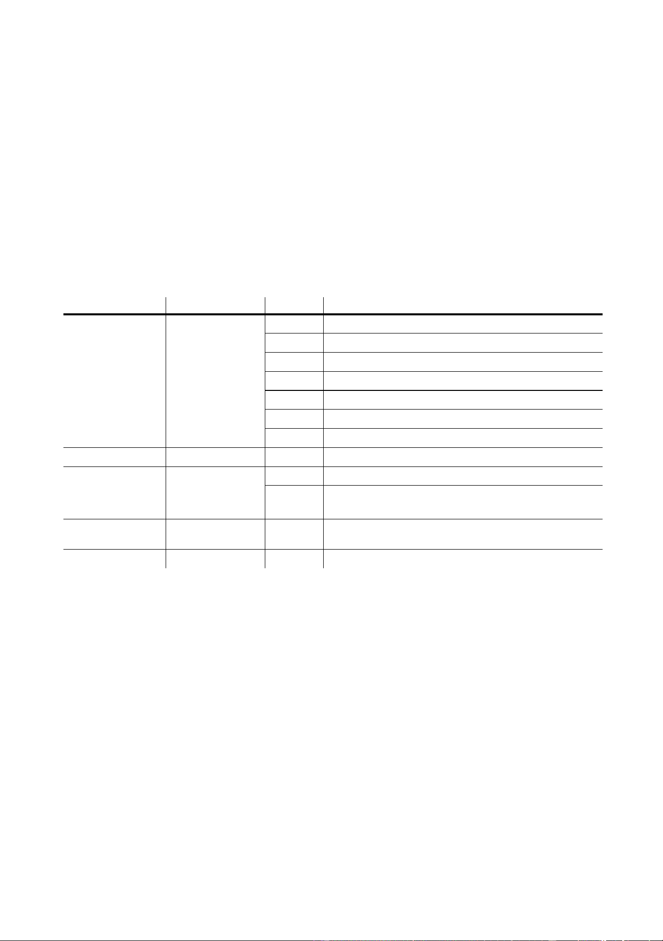
Snoot
The snoot may be installed to reduce light spill to the sides.
To install the snoot
1 Bend the tabs 90°.
2 Bend the ring into a circle with the tabs on the outside. Weave the end tab through the 3 slots.
3 Insert the tabs between the 3 pairs of pins between the lens and the head cover.
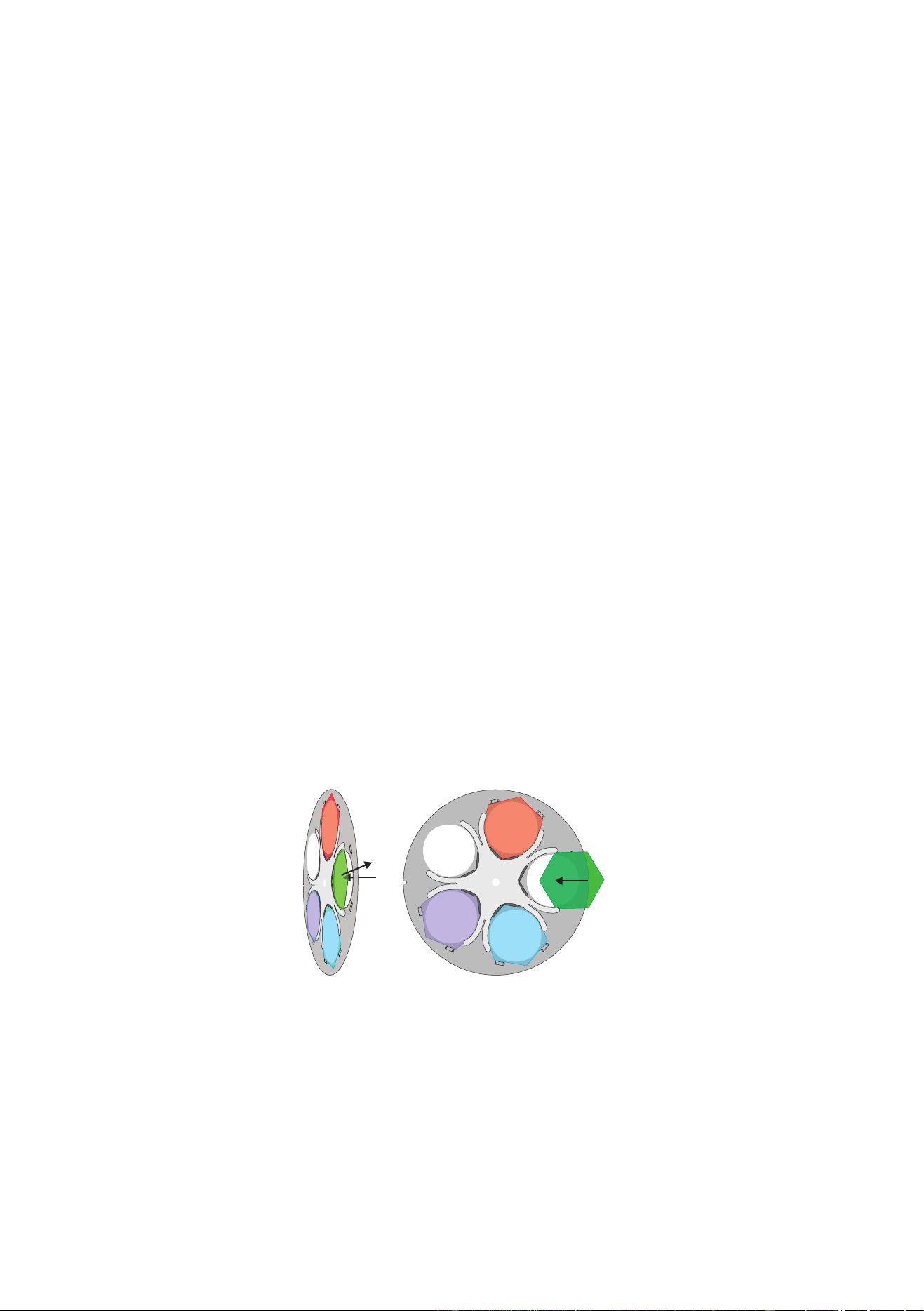
Diffuser filter
The MAC 600 (E) NT includes a removable diffuser filter that provides a flatter field and superior color uniformity.
For special applications, a 90 x 90 mm glass color filter may be installed in place of the diffuser.
To remove or install the diffuser filter
1 Disconnect the fixture from AC power and allow it to cool.
2 Unlatch and remove the front section of the head.
3 Remove the screw, washer, and retention spring from each end of
the filter holder as shown. Lift off the holder and filter.
4 Replace the filter holder or store it with the filter.
5 Filter installation is the reverse. Turn the diffuser glass so that the
textured side is away from the lamp.
123

20
MAC 600 (E) NT
O
PERATION
9
DMX-512 control
The MAC 600 (E) NT may be controlled with any DMX-512 controller. Four DMX modes are available that provide
different combinations of speed control and pan/tilt resolution.
TRACKING MODE
Tracking mode is available in all 4 DMX modes. In tracking mode the speed at which an effect moves is determined by
the controller’s fade time. The effect tracks the fade from one DMX value to another and a digital filter algorithm
ensures smooth movement at all fade speeds.
Two tracking algorithms are available to optimize movement for any controller. Algorithm 1 is recommended for use
with most controllers. Algorithm 2 provides smoother movement if the controller’s DMX value changes are uneven.
The number of DMX value changes used to calculate smooth movement is selectable between a level of 1 and 10. The
default level works well with most controllers. Increasing the level makes movement smoother but less responsive to
sudden DMX changes. Experiment for best results.
VECTOR MODE
Vector control is available in DMX modes 3 and 4. This mode provides direct speed control using 2 speed channels
and may result in smoother movement when using a controller with a slow or irregular refresh rate. Vector mode also
provides a “blackout” speed and overrides of the pan/tilt speed (PTSP), shortcut (SCUT), and studio mode (MOdE)
settings.
When vector control is used, the controller fade time should be set to 0, i.e., the position bumps from one value to the
next. However, tracking control may be enabled in vector mode by setting the speed channels to a tracking value.
8-BIT MODE
8-bit pan and tilt control is provided in DMX modes 1 and 3. This mode provides 256 pan positions in 1.7° steps and
256 tilt positions in 1.2° steps.
16-BIT MODE
16-bit pan and tilt control requires 2 additional channels and is available in DMX modes 2 and 4. This mode provides
32,768 pan positions in 0.013° steps and 45,567 tilt positions in 0.007° steps.
Lamp
The MAC 600 (E) NT can be set to automatically strike within 90 seconds of being powered on by setting Automatic
Lamp On (
SPEC/ALON) to ON. A delay determined by the fixture address prevents all lamps from striking at the
same time.
If Automatic Lamp On is set to off, the default, the lamp remains off until a “lamp on” command is sent from the
controller. Note: A peak of electric current that can be many times the operating current is drawn for an instant when
striking the lamp. Striking many lamps at once may cause a voltage drop large enough to prevent lamps from striking
or trip the main circuit breaker. Avoid this by programming a “lamp on” sequence that strikes lamps one at a time at 5
second intervals.
Mode DMX 1 DMX 2 DMX 3 DMX 4
Movement speed Tracking Tracking and/or Vector
Pan/tilt resolution 8 bit 16 bit 8 bit 16 bit
Channels 11 13 13 15

Operation
21
The lamp can be turned off from the controller. The DMX lamp off command is executed if DMX lamp off (SPEC/
dLof
) is set to ON. Note: It is not possible to strike the lamp within 8 minutes of having switched it off. If DMX
lamp off is OFF, the lamp off command can only be executed if the cyan, magenta, and yellow channels are set to a
value from 230 to 232.
With the MAC 600 E NT, lamp power falls to 400 watts for cooler operation and longer lamp life when the shutter is
closed for 10 seconds. Power instantly returns to full when the shutter opens. Reduced-power mode with the shutter
open can be forced by setting channel 1 to a DMX value from 116 to 122.
Mechanical effects
All mechanical effects are reset to their home position when the fixture is powered up, and the fixture can be reset from
the controller. A controller reset command is executed if DMX reset (
SPEC/dRES) is set to ON. If DMX reset is
OFF, the reset command can only be executed if the cyan, magenta, and yellow channels are set to a value from 230 to
232.
An on-the-fly position correction system monitors the dimmer, color wheel, and beam shaper position. If a position
error occurs in one of these effects, the shutter closes while the effect automatically resets. This feature may be
disabled by setting effects feedback (SPEC/EFFb) to OFF.
General operation may be optimized for speed or quietness with the studio mode setting (
MOdE).
PAN AND TILT
The moving head can be panned 440° and tilted 306°. The middle of the pan range is perpendicular to the front of the
fixture, as indicated by the arrow on the base. Movement may be optimized for speed by setting the pan/tilt speed
(
PTSP) personality to FAST, or for smoothness by setting it to NORM. The setting may be overridden on the
speed channel in vector mode. Movement is disabled if lamp feedback is lost - indicating a blown lamp - to prevent
possible damage or injury due to glass fragments.
Setting the movement speed to “blackout” in vector mode causes the shutter to black out the light while the head is
moving. The pan and tilt DMX channels can be inverted and/or swapped for convenience using the pan/tilt (
PATI)
menu.
COLOR WHEEL
The color wheel provides dichroic red, green, blue, and UV color filters. The wheel can be scrolled, allowing for split
color effects, snapped to fixed positions, and continuously rotated in both directions at different speeds. The Shortcuts
(
SPEC/SCUT) setting determines whether the wheel takes the shortest path to the next position or swings between
the end positions. The setting may be overridden on the speed channel in vector mode.
Setting the color speed to “blackout” in vector mode causes the shutter to black out the light while the wheel moves,
making the transition invisible.
CMY COLOR MIXING
The CMY color mixing system uses continuous dichroic cyan, magenta, and yellow color filters. It is a subtractive
system that removes the unwanted colors from white light. Inserting all three filters results in loss of light: for
maximum brightness, mix 2 colors at a time.
Random CMY color mixing is available at the top of channel 7.
COLOR TEMPERATURE CORRECTION
The color temperature correction (CTC) system uses a continuous 0 - 178 mireds color correction filter. The range of
color temperatures available with a new lamp is shown below. As the source color temperature varies, DMX values for
specific color temperatures cannot be stated.
Source Color Temperature Range Color Rendering Index
Osram HSR 575/2 6000 - 2900 K 95
Philips MSD 575 6000 - 2900 K 75
Philips MSR 575/2 7200 - 3150 K 80

22
MAC 600 (E) NT
BEAM SHAPER
The beam shaper widens the beam on one axis and flattens it on the other. The effect rotates 180°. The Shortcuts
(
SPEC/SCUT) setting determines whether the beam shaper takes the shortest path to the next position or swings
between the end positions. The setting may be overridden on the speed channel in vector mode.
VARIABLE FROST
The variable frost system softens and widens the beam, thus providing a zoom effect.
DIMMER
The mechanical dimmer provides smooth, high-resolution dimming from full-closed to full-open. The Shortcuts
(SPEC/SCUT) setting determines whether the dimmer takes the shortest path to the next position or swings between
the end positions. The setting may be overridden on the speed channel in vector mode.
SHUTTER
The high-speed mechanical shutter opens and closes instantly and flashes the light at speeds up to 8 Hz.
With the automatic shutter function (SPEC/ASHT) enabled, the shutter works in tandem with the dimmer to
automatically provide faster blackouts than the dimmer alone can provide.

Updating software
23
U
PDATING
SOFTWARE
10
The latest software and documentation for the MAC 600 (E) NT is available from the Martin Professional web site.
Software installation requires a Martin uploader, such as the MPBB1, prepared with the latest fixture software. The
DMX interface card provided with the Club version of the Martin LightJockey controller also supports software
upload.
To install software with the MPBB1 uploader, normal method
1 Download the latest MAC 600 (E) NT CPU firmware from the Martin web site at http://www.martin.dk. Load
the software into the uploader as described in the MPBB1 manual.
2 Connect the uploader to the fixture as you would a controller.
The data link must be terminated.
Apply power
to the uploader and the fixtures.
3 After the fixture has finished resetting, select
UPLd from the MPBB1 menu and press [ENTER]. Select
dMX and press [ENTER].
4 Wait. The software has been installed when the MPBB1 displays
dONE and the fixtures reset. Turn off and
disconnect the MPBB1.
5 If a check-sum error occurs and/or the fixture does not reset, data was interrupted or corrupted during
transmission. Reattempt the upload using backup method I.
To install software with the MPBB1, backup method I
Follow this procedure to install software if a normal upload attempt is unsuccessful.
1 Disconnect the fixture from power: it must be off at least 10 seconds.
Do not apply power to the fixture until
the uploader is connected and ready.
2 Connect the uploader to the fixture as you would a controller.
Terminate the link
.
3Select UPLd from the uploader menu and press [ENTER]. Select boot
but do not press [ENTER].
4 Apply power to the fixture.
5 When the fixture display reads
boot, press [ENTER] on the uploader. If the fixture display shifts between
CSER and boot, press [ENTER] 5 seconds after the display changes to boot. The timing must be
exact.
6 Wait. When the fixture resets, the software has been installed successfully. Disconnect the uploader.
To install software with the MPBB1, backup method II
Use this procedure to install software if all else fails or if a boot sector upload is recommended in the update notes.
1 Disconnect the fixture from power.
2 Remove the printed circuit board and move the boot
sector jumper to the boot setting. Reconnect any
unplugged wires.
3 Connect the uploader to the fixture as you would a
controller.
Terminate the link
.
4Select UPLd from the uploader menu and press [ENTER]. Select boot.
Do not press [ENTER].
5 Apply power to the fixture and wait 5 seconds. Press [ENTER] on the uploader.
6 Wait. The software has been installed when the fixture resets.
7 Disconnect the fixture from power, move the jumper back to the normal setting, and replace the circuit
board.
1
PL121
INIT
1
PL121
INIT
normal settingboot setting
24
MAC 600 (E) NT
F
IXTURE
SERVICE
11
Excessive dust, grease, and smoke fluid buildup can result in damage that is not covered by the warranty. Dirty lenses
and filters transmit less light, absorb more heat, and are subject to heat damage. Dirty fans and air vents reduce cooling
and generally shorten component life. This section takes you through the general maintenance procedures and
describes some basic service operations.
Warning! Disconnect from AC power before removing any cover or part.
Circuit board service
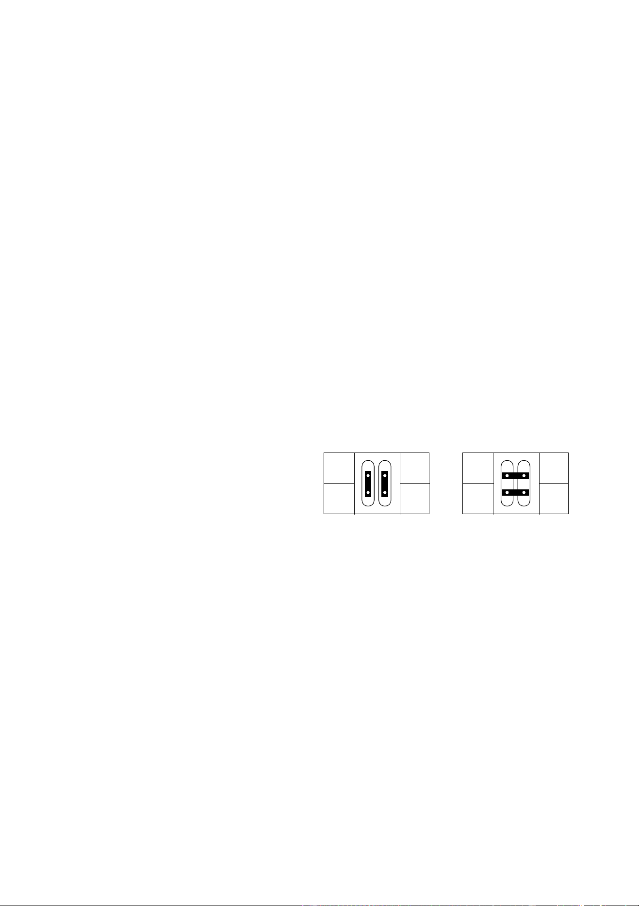
To replace fuses or change the XLR pin-out
The main fuse is located above the XLR output and is replaced by unscrewing the holder with a screwdriver or small
coin. The secondary fuses are located on the printed circuit board and are replaced as follows.
1 Disconnect the fixture from AC power.
2 Remove the top plate from the front of the base.
Do not remove the curved side plates.
3 Unplug the white plastic connectors from the top of the printed circuit board. To unplug a connector, hold the
plastic connector - never pull the wires - and pull it straight off the pins.
4 Grasp the black pins on either end of the circuit board and gently pull it out. You may have to guide some
wires past the motor housing. Be careful not to knock the copper heat sinks.
5 Replace defective fuses with ones of the same rating. The fuses values are listed on page 30.
6 To change the XLR pin out, position the
jumpers for the desired XLR pin-out as
shown.
7 Gently put the circuit board into the base.
You may have to guide some wires past
the motor housing. Push the black pins
down to lock the board in place.
8 Reconnect all wires as shown on page 29. Replace the top cover.
Cleaning the optical path
Cleaning and servicing components in the head is best left to qualified Martin technicians.
To access the optical components, remove the head cover. Remember to attach the internal safety cable when
reassembling the head.
Be very careful if you clean the optical components. The colored surface on the dichroic filters is achieved by means of
special multi-layer coatings and even small scratches in these might be visible. Residues left from cleaning fluids can
bake onto and ruin components.
Wash dirty lenses and filters with isopropyl alcohol. Rinse with distilled water: mixing the water with a small amount
of wetting agent such as Kodak Photoflo will help prevent streaking and spotting. Dry with a clean, soft and lint-free
cloth or blow dry with compressed air. A generous amount of regular window glass cleaner may also be used, but no
residues may remain.
Cleaning the fans
To ensure proper cooling of the fixture it is important that the fans are free of dust. Clean the fans with a vacuum or
damp cloth if they are dirty.
2
3
+
-
2
3
+
-
DMX pin-outMartin pin-out
DMX protocol
25
DMX
PROTOCOL
A
DMX channel Start code = 0
DMX1 DMX2 DMX3 DMX4 Value Percent Function
1
Note:
Lamp Off is allowed with SPEC/dLoF set
to ON, or with SPEC/dLoF set to OFF
and cyan, magenta and yellow set
between 230 and 232.
Reset is allowed with SPEC/dRES set to
ON, or with SPEC/dRES set to OFF and
cyan, magenta and yellow set between
230 and 232.
0 - 19
20 - 49
50 - 112
113 - 115
116 - 122
123 - 127
128 - 147
148 - 167
168 - 187
188 - 207
208 - 217
218 - 227
228 - 237
238 - 247
248 - 255
0 - 7
8 - 19
20 - 44
44 - 45
45 - 48
48 - 50
50 - 58
58 - 65
66 - 73
74 - 81
82 - 85
85 - 89
89 - 93
93 - 97
97 - 100
Shutter, Strobe, Reset, Lamp On/Off
Shutter closed
Shutter open
Strobe on (fast->slow)
Shutter closed
Shutter open (Reduced lamp power w/electronic ballast)
Shutter closed
Random strobe, fast
Random strobe, medium
Random strobe, slow
Shutter closed
Reset fixture
Shutter closed
Lamp power on
Shutter closed
Lamp power off Note: T ≥ 5 seconds
2
0 - 255 0 - 100
Intensity
0
Æ
100%
3
0 - 255 0 - 100
Cyan
White
Æ
Cyan
4
0 - 255 0 - 100
Magenta
White
Æ
Magenta
5
0 - 255 0 - 100
Yellow
White
Æ
Yellow
6
0 - 255 0 - 100
CTC
Cold
Æ
Warm (0-178 mireds)
7
0 - 40
40 - 80
80 - 120
120 - 160
161 - 165
166 - 170
171 - 175
176 - 180
181 - 185
186 - 214
215 - 243
244 - 247
248 - 251
252 - 255
0 - 16
16 - 31
31 - 47
47 - 63
63 - 65
65 - 67
67 - 69
69 - 71
71 - 73
73 - 84
84 - 95
96 - 97
97 - 98
99 - 100
Color Wheel
Continuous scroll
White
Æ
Color 1
Color 1
Æ
Color 2
Color 2
Æ
Color 3
Color 3
Æ
Color 4
Stepped scroll
Color 4
Color 3
Color 2
Color 1
White
Continuous rotation
CW, fast
Æ
slow
CCW, slow
Æ
fast
Random CMY color
Random color, fast
Random color, medium
Random color, slow
80
1 - 255
0
0 - 100
Beam Shaper
Open
Beam shaper left
Æ
right
9
0 - 255 0 - 100
Frost
No frost
Æ
full frost
10
0 - 255 0 - 100
Pan Coarse (16-bit MSB)
Left
Æ
right (128 = neutral)
-11-11
0 - 255 0 - 100
Pan Fine (16-bit LSB)
Left
Æ
right
11 12 11 12
0 - 255 0 - 100
Tilt Coarse (16-bit MSB)
Up
Æ
down (128 = neutral)

26
MAC 600 (E) NT
-13-13
0 - 255 0 - 100
Tilt Fine (16-bit LSB)
Up
Æ
down
- - 12 14
0 - 2
3 - 245
246 - 248
249 - 251
252 - 255
0 - 1
1 - 96
96 - 97
98 - 98
99 - 100
Speed: Pan, Tilt
Tracking
Fast
Æ
slow
Tracking, PTSP = NORM (normal pan/tilt speed)
Tracking, PTSP = FAST (fast pan/tilt speed)
Blackout
- - 13 15
0 - 2
3 - 239
240 - 242
243 - 245
246 - 248
249 - 251
252 - 255
0 - 2
3 - 239
240 - 242
243 - 245
246 - 248
249 - 251
252 - 255
0 - 1
1 - 94
94 - 95
95 - 96
96 - 97
98 - 98
99 - 100
0 - 1
1 - 94
94 - 95
95 - 96
96 - 97
98 - 98
99 - 100
Speed: Dimmer, Color Mix, Bm Shaper, Frost
Tracking
Fast
Æ
slow
Tracking, MOdE = NORM (studio mode off)
Tracking, MOdE = STUd (studio mode on)
Tracking, SCUT = OFF (shortcuts off)
Tracking, SCUT = ON (shortcuts on)
Fast
Speed: Color wheel
Tracking
Fast
Æ
slow
Tracking, MOdE = NORM (studio mode off)
Tracking, MOdE = STUd (studio mode on)
Tracking, SCUT = OFF (shortcuts off)
Tracking, SCUT = ON (shortcuts on)
Blackout
DMX channel Start code = 0
DMX1 DMX2 DMX3 DMX4 Value Percent Function
Display messages
27
D
ISPLAY
MESSAGES
B
Display readout Appears if... What to do
SRST (Serial reset)
...the fixture receives a reset command from
the controller.
To prevent accidental resets, disable
command. See page 13.
LERR (Lamp error)
.... the lamp doesn’t ignite within 10 minutes of
receiving the ‘Lamp ON’ command. Likely
reasons are a missing or defective lamp, or
insufficient AC voltage.
Check the lamp and check that the
mains setting of the fixture matches the
mains supply.
MERR (Memory error) ...the EEPROM memory cannot be read. Contact Martin technician for assistance.
CSER (Check-sum error) ...a software upload is not successful. Upload software again, see page 23.
****
... there is no communication between the
control module and motherboard. This readout
appears briefly when switching on the fixture.
Check fuses on motherboard and
replace accordingly.
Check that ribbon cable between control
module and motherboard is connected
properly.
ShER (Short error)
... the fixture detects that the lamp is ON but
no ‘Lamp ON’ command has been received.
This can occur if the lamp relays are stuck in
the ON position or if the lamp-power feedback
circuit has failed. You can still operate the
fixture but may not be able to remotely switch
off the lamp.
Contact Martin technician for assistance.
Hot (Hot lamp)
... you attempt to strike the lamp within 8
minutes after having switched it off. The fixture
will store the ‘Lamp ON’ instruction and strike
the lamp once the 8 minutes have elapsed.
Wait until the lamp strikes.
bTER (Base temperature error)
HTER (Head temperature error)
...there is a malfunction in the base or head
temperature sensing circuit.
Contact Martin technician for assistance.
FbEP (Feedback error pan)
FbET (Feedback error tilt)
FbER (Feedback error pan/tilt)
...pan (FbEp), tilt (FbET) or both (FbER)
feedback circuits are malfunctioning. It will still
be possible to operate the fixture, though it
goes into a “safe” mode where maximum
speed is reduced, thus preventing the fixture
from losing track of its home position (losing
step).
Contact Martin technician for assistance.
PAER (Pan time-out)
TIER (Tilt time-out)
CYER (Cyan time-out)
MAER (Magenta time-out)
YEER (Yellow time-out)
CTER (CTC time-out)
...the microswitch indexing circuit
malfunctions. The effect defaults to a
mechanical stop and continues to work
normally.
Contact Martin technician for assistance.
DIER (Dimmer time-out)
COER (Color time-out)
bSER (Beam shaper 1 time-out)
...the magnetic-indexing circuit malfunctions.
After the time-out, the effect stops in a random
position.
Contact Martin technician for assistance.
28
MAC 600 (E) NT
T
ROUBLESHOOTING
C
Problem Probable cause(s) Remedy
One or more of the fixtures is
completely dead.
Fixture not powered on.
Check that power is switched on and cables are
plugged in.
Primary fuse blown (located at the
mains inlet cable).
Disconnect fixture and replace fuse.
Secondary fuse(s) blown (located on
PCB inside the fixture base).
Disconnect fixture. Check fuses on PCB (F601 and
F602) and replace.
Fixtures reset correctly but all
respond erratically or not at all to the
controller.
The controller is disconnected from the
data link.
Connect controller.
XLR pin-out of the controller does not
match pin-out of the first fixture on the
link (i.e. signal is reversed).
Install a phase-reversing cable between the
controller and the first fixture on the link.
Fixtures reset correctly but some
respond erratically or not at all to the
controller.
Bad data link connection
Inspect connections and cables. Correct poor
connections. Repair or replace damaged cables.
Data link not terminated with 120Ω
termination plug.
Insert termination plug in output jack of the last
fixture on the link.
Incorrect addressing of the fixtures.
Check fixture address and protocol settings.
(page 12)
One of the fixtures is defective and
disturbs data transmission on the link.
Bypass one fixture at a time until normal operation
is regained. Do this by unplugging the XLR in and
out connectors and connecting them directly
together. Have the fixture serviced by a qualified
technician.
XLR pin-out on fixtures does not match
(pins 2 and 3 reversed).
Install a phase-reversing cable between the fixtures
or swap pins 2 and 3 in the fixture that behaves
erratically.
No light and “LERR” error message
displayed.
The ballast and transformer settings do
not match local AC voltage and
frequency.
Disconnect fixture. Check ballast and transformer
settings and correct if necessary.
Lamp blown Disconnect fixture and replace lamp.
Lamp not installed Disconnect fixture and install lamp.
Lamp cuts out intermittently.
Fixture is too hot.
Allow fixture to cool.
Reduce ambient room temperature.
Set fan speed to full.
Recalibrate temperature sensors.
The ballast and transformer settings do
not match local AC voltage and
frequency.
Disconnect fixture. Check ballast and transformer
settings and correct if necessary.
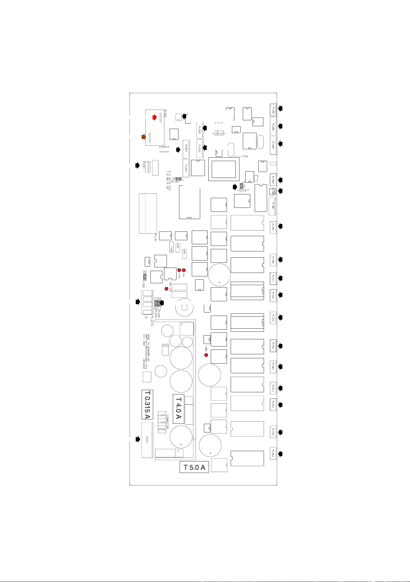
Circuit board connections
29
C
IRCUIT
BOARD
CONNECTIONS
D
OPTO2
OPTO1
To display panel
Red
XLR polarity jumper
To transformer
FAN
To base fan
CTC
DIM
CYAN
MAG
YEL
COLOR
BEAM1
SHUTTER
FROST
TILT
PAN
Brown
Black
Boot sector jumper
P/T SW
CMY SW
SENSOR
To XLR socket
To electronic ballast
(E version only)
30
MAC 600 (E) NT
S
PECIFICATIONS
E
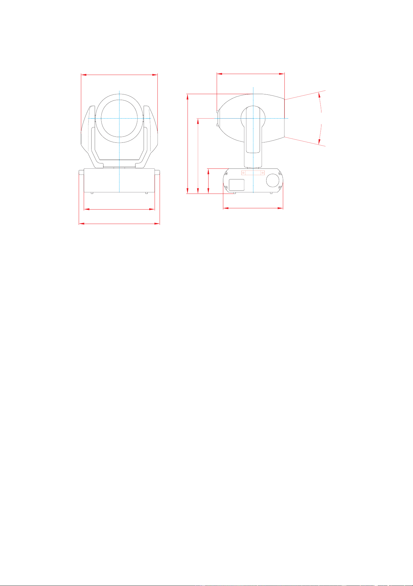
MEASUREMENTS
Dimensions (LxWxH) without clamps . . . . . . . . . . . . . . . . . . . . . . . . . . . . . . . . . . . . . . . .481 x 356 x 652 mm (18.9 x 14.0 x 25.7 in)
Minimum rigging distance, center to center . . . . . . . . . . . . . . . . . . . . . . . . . . . . . . . . . . . . . . . . . . . . . . . . . . . . . . . . . . 457 mm (18 in)
Weight (without clamps), MAC 600 NT . . . . . . . . . . . . . . . . . . . . . . . . . . . . . . . . . . . . . . . . . . . . . . . . . . . . . . . . . . . . 31.5 kg (69.3 lb)
Weight, without clamps, MAC 600 E NT . . . . . . . . . . . . . . . . . . . . . . . . . . . . . . . . . . . . . . . . . . . . . . . . . . . . . . . . . . . 25.4 kg (55.9 lb)
ELECTRICAL, MAC 600 NT
Wiring options . . . . . . . . . . . . . . . . . . . . . . . . . . . . . . . . . . . . . . . . . . . . . . . . . . . . . . . . . . . . . 200/230/245 V, 50 Hz; 208/227 V, 60 Hz
Power and current . . . . . . . . . . . . . . . . . . . . . . . . . . . . . . . . . . . . . . . . . . 750 W, 3.9 A @ 230 V/50 Hz; 750 W, 4.2 A @ 208 V/60 Hz
Power factor (PF). . . . . . . . . . . . . . . . . . . . . . . . . . . . . . . . . . . . . . . . . . . . . . . . . . . . . . . . . . . . . . . . . . . . . . . . . . . . . . . . . . . . . . . . 0.85
ELECTRICAL, MAC 600 E NT
Transformer taps . . . . . . . . . . . . . . . . . . . . . . . . . . . . . . . . . . . . . . . . . . . . . . . . . . . . 100/110/120/200/210/220/230/240 @ 50 - 60 Hz
Power and current . . . . . . . . . . . . . . . . . . . . . . . . . . . . . . . . . . . . . . . . . . . . . . . . . . . . . . . . . . . . . . . . . .690 W, 3.2 A @ 230 V / 50 Hz
Power factor (PF). . . . . . . . . . . . . . . . . . . . . . . . . . . . . . . . . . . . . . . . . . . . . . . . . . . . . . . . . . . . . . . . . . . . . . . . . . . . . . . . . . . . . . . . 0.94
FUSES
Primary fuse @ 200 - 250 V AC . . . . . . . . . . . . . . . . . . . . . . . . . . . . . . . . . . . . . . . . . . . . . . . . . . . . . . . . . . . . . . . . . . . T 6.3 A, 250 V
Primary fuse @ 100 - 130 V AC (MAC 600 E NT only) . . . . . . . . . . . . . . . . . . . . . . . . . . . . . . . . . . . . . . . . . . . . . . . T 10.0 A, 250 V
Fuse F601 . . . . . . . . . . . . . . . . . . . . . . . . . . . . . . . . . . . . . . . . . . . . . . . . . . . . . . . . . . . . . . . . . . . . . . . . . . . . . . . . . . . . .T 5.0 A, 250 V
Fuse F602. . . . . . . . . . . . . . . . . . . . . . . . . . . . . . . . . . . . . . . . . . . . . . . . . . . . . . . . . . . . . . . . . . . . . . . . . . . . . . . . . . . . . .T 4.0 A, 250 V
Fuse F603. . . . . . . . . . . . . . . . . . . . . . . . . . . . . . . . . . . . . . . . . . . . . . . . . . . . . . . . . . . . . . . . . . . . . . . . . . . . . . . . . . . .T 0.315 A, 250 V
COMMUNICATION
Protocol . . . . . . . . . . . . . . . . . . . . . . . . . . . . . . . . . . . . . . . . . . . . . . . . . . . . . . . . . . . . . . . . . . . . . . . . . . . . . . . USITT DMX512 (1990)
DMX start code . . . . . . . . . . . . . . . . . . . . . . . . . . . . . . . . . . . . . . . . . . . . . . . . . . . . . . . . . . . . . . . . . . . . . . . . . . . . . . . . . . . . . . . . . . . .0
Recommended cable . . . . . . . . . . . . . . . . . . . . . . . . . . . . . . . . . . . . 24 AWG (min.), low capacitance, 85-150 Ω shielded twisted pair
Connector type . . . . . . . . . . . . . . . . . . . . . . . . . . . . . . . . . . . . . . . . 3-pin XLR male/female (pin 1: screen, pin 2: data -, pin 3: data +)
COMPATIBLE LAMPS
Osram HSR-575/2 . . . . . . . . . . . . . . . . . . . . . . . . . . . . . . . . . . . . . . . . . . . . . . . . . . 575 W, 85 lm/W, 1000 hr., 6000 K, P/N 97010200
Philips MSR-575/2. . . . . . . . . . . . . . . . . . . . . . . . . . . . . . . . . . . . . . . . . . . . . . . . . . 575 W, 85 lm/W, 1000 hr., 7200 K, P/N 97010201
Philips MSD-575 . . . . . . . . . . . . . . . . . . . . . . . . . . . . . . . . . . . . . . . . . . . . . . . . . . . 575 W, 75 lm/W, 2000 hr., 6000 K, P/N 97010202
25°
437
579
145
356
403
420
481
456
dimensions in millimeters

Specifications
31
THERMAL
Maximum ambient temperature. . . . . . . . . . . . . . . . . . . . . . . . . . . . . . . . . . . . . . . . . . . . . . . . . . . . . . . . . . . . . . . . . . . . 40° C (104° F)
Maximum surface temperature under normal conditions . . . . . . . . . . . . . . . . . . . . . . . . . . . . . . . . . . . . . . . . . . . . . . . .140° C (284° F)
ACCESSORIES
18° “long front” with lens . . . . . . . . . . . . . . . . . . . . . . . . . . . . . . . . . . . . . . . . . . . . . . . . . . . . . . . . . . . . . . . . . . . . . . . . . . . . .91610005
65° floodlight diffuser on standard front . . . . . . . . . . . . . . . . . . . . . . . . . . . . . . . . . . . . . . . . . . . . . . . . . . . . . . . . . . . . . . . . . .91610008
MPBB1 Uploader. . . . . . . . . . . . . . . . . . . . . . . . . . . . . . . . . . . . . . . . . . . . . . . . . . . . . . . . . . . . . . . . . . . . . . . . . . . . . . . . . . . .90758410
G-clamp . . . . . . . . . . . . . . . . . . . . . . . . . . . . . . . . . . . . . . . . . . . . . . . . . . . . . . . . . . . . . . . . . . . . . . . . . . . . . . . . . . . . . . . . . . .91602003
Half-coupler clamp. . . . . . . . . . . . . . . . . . . . . . . . . . . . . . . . . . . . . . . . . . . . . . . . . . . . . . . . . . . . . . . . . . . . . . . . . . . . . . . . . . .91602005
Clamp adaptor with 1/4-turn fasteners. . . . . . . . . . . . . . . . . . . . . . . . . . . . . . . . . . . . . . . . . . . . . . . . . . . . . . . . . . . . . . . . . . . .91602001
Outdoor Protection Dome . . . . . . . . . . . . . . . . . . . . . . . . . . . . . . . . . . . . . . . . . . . . . . . . . . . . . . . . . . . . . . . . . . . . . . . . . . . . .90525010
2 unit flight case. . . . . . . . . . . . . . . . . . . . . . . . . . . . . . . . . . . . . . . . . . . . . . . . . . . . . . . . . . . . . . . . . . . . . . . . . . . . . . . . . . . . .91510002
fast
slow
T PAN/TILT SPEED
2
10 20 30 40 50 60 70 80 90
closed open
S
TROBE RANDOM STROBE
med slow
RESET LAMP
ON
SHUTTER
fast
LAMP
OFF*
← *
> 5 sec.
MODE
T
E
FFECTS SPEED
DIMMER closed open
180°
BEAM SHAPER
PAN
TILT FINE (LSB)up down
fdimmer, CMY, CTC, beam shaper, frost
color wheel
«·»
T
PAN FINE (LSB)left right
TILT
1
3
4
5
8
9
10
1111
1111 1212
-1313
12 14
13 15
--
3142
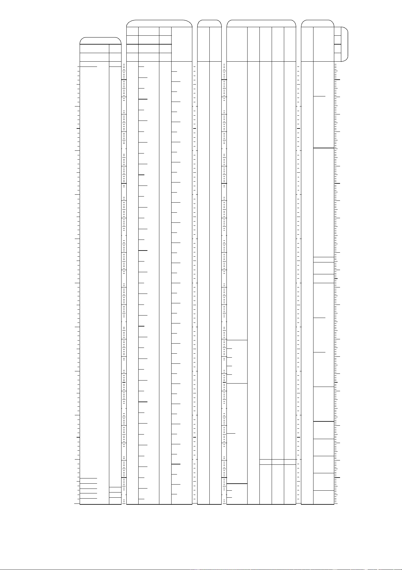
MAC 600 NT DMX Protocol
Start code = 0
* Set CMY from 230 to 232 to override disabled function.
M
N
= normal mode, M
S
= studio mode
T = tracking mode (0-2 & 246-251)
S = normal PTSP or shortcuts off (246-248)
F = fast PTSP or shortcuts on (249 -251)
«·» = blackout speed (252-255)
← = variable speed, points to fast
25 50 75 100 125 150 175 200 225 250
L
I
G
H
T
P
/
T
S
P
E
E
D
-
T
S
T
F
T
S
T
F
T
S
T
F
«·»
B
/
O
B/O B/O B/O
MAGENTA 0% 100%
CYAN 0% 100%
YELLOW 100%
RND.
CMY
CONTINUOUS COLOR SCROLL STEPPED
S
CROLL
CONTINUOUS ROTATION
cw ← ccw →
43210
(1) red, DMX 40 (2) green, DMX 80 (3) blue, DMX 120 (4) UV, DMX 160
7
0° (open)
F
ROST 0%
25 50 75 100 125 150 175 200 225 250
B
E
A
M
25 50 75 100 125 150 175 200 225 250
fms
10 20 30 40 50 60 70 80 90
10 20 30 40 50 60 70 80 90
C
O
L
O
R
*
*
*
(0) white, DMX 0
190°
210°
150°170° 110°130° 90° 50° 30° 10°70° 30°
10°
70°50° 110°90° 130° 170° 190° 210°150°
135°150° 105°120° 75°90° 60° 30° 15°45° 30°15° 60°45° 90°75° 105° 135°120°0°
left
up
right
down
150°
B
/
O
low
pwr
(E)
M
N
M
S
M
N
M
S
Implemented from CPU software version 1.0
6 COLOR TEMPERATURE CORRECTIONcold (0 mireds) warm (178 mireds)
180°
100%
slow
slow
fast
fast
