
TABLE OF CONTENTS
7/16 in/po
(≈11 mm)
3/8 in/po
(≈10 mm)
5/16 in/po (≈8 mm) Drill Bit
GHO 5/32 in/po (≈4 mm) Drill Bit (*)
5/16 in/po (≈8 mm) Masonry Drill Bit
Pour le français, voir la page 2. Para el español, ver la página 3.
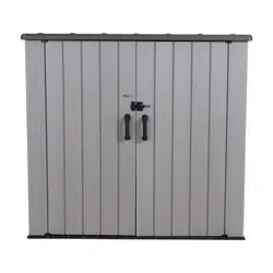
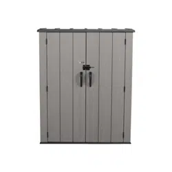
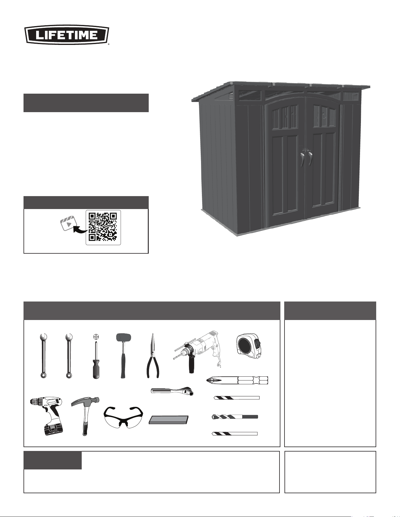
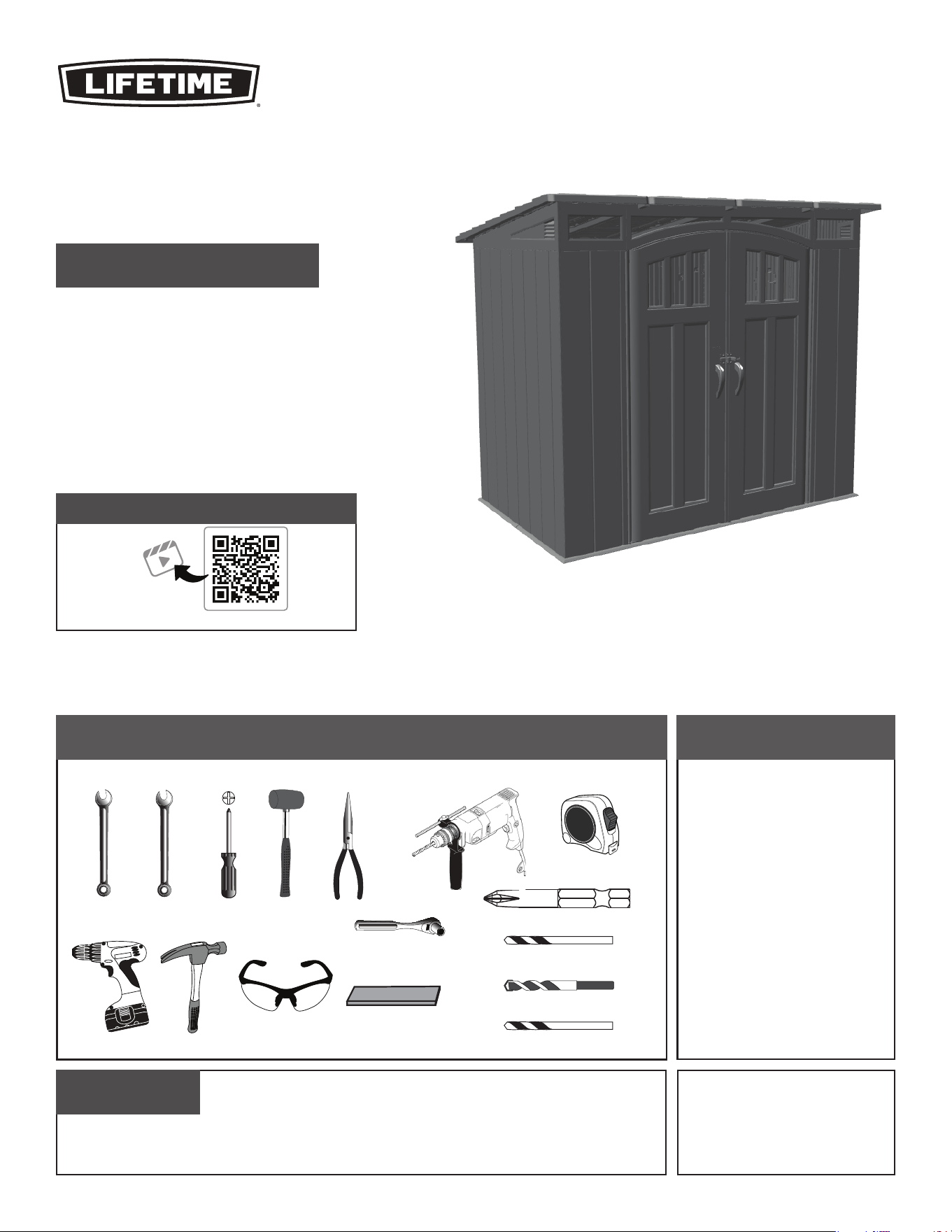
ASSEMBLY INSTRUCTIONS
OUTSIDE
SHED
MODEL 60461
BEFORE ASSEMBLY:
• Assemble on a level platform.
• At least 3 people recommended for setup.
• Inspect all parts and hardware. Ensure all are included using
the
Parts Identifi er
in the middle of these instructions.
The
Parts Identifi er
, in yellow, can be removed from the
instructions for quick reference.
Icon legend.........................................................4
Warnings & notices.............................................5
Platform construction.........................................6
Door assembly..................................................11
Floor assembly..................................................26
Wall assembly...................................................29
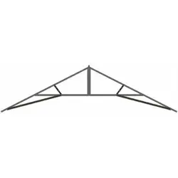
Transom & gable assembly...............................35
Shelving installation..........................................49
Parts identifi er................................................i–iv
Roof assembly..................................................52
Wall hook installation........................................84
Door alignment.................................................86
Shed anchoring.................................................88
Cleaning & care................................................94
Registration...............................................95
Warranty..................................................96
FOR OUTDOOR DOMESTIC USE ONLY!
IMPORTANT, RETAIN FOR FUTURE REFERENCE: READ CAREFULLY
ADC (x1)*
AIW (x1)*
3/8 in/po
(≈10 mm)
QUESTIONS?
For Customer Service in mainland Europe and
the United Kingdom, email:
CONTACT LIFETIME CUSTOMER SERVICE:
Call:
1-800-225-3865
(English, French, Spanish)
Live Chat:
www.lifetime.com/customerservice/home
(click on "LIVE CHAT" tab)
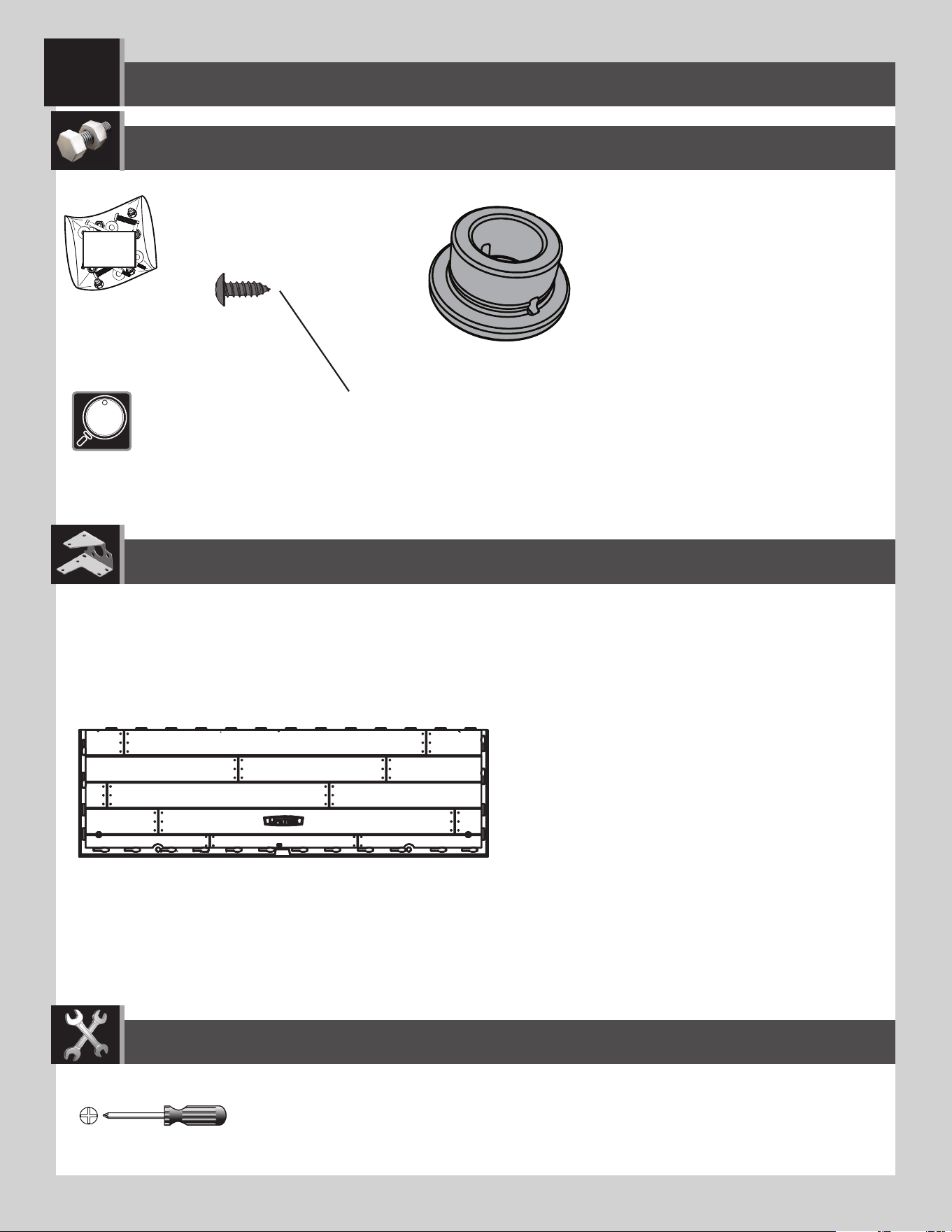
TOOLS REQUIRED
(Not included—unless otherwise indicated*)
Scan the code, or visit go.lifetime.com/60387-fullassembly
WATCH THE INSTRUCTIONAL VIDEO
Product ID:
2
AVANT L’ASSEMBLAGE :
• Assembler sur une plate-forme nivelée.
• Nous recommandons, au moins, 3 adultes pour l’assemblage.
• Examiner toutes les pieces et quincaillerie. Vérifi er qu’elles sont
incluses en utilisant l’
Identifi cateur de pièces
au milieu de ces
instructions. Il est posssible enlever l’
Identifi cateur de pièces
, en
jaune, des instructions pour référence rapide.
For English, see page 1. Para el español, ver la página 3.
INSTRUCTIONS D’ASSEMBLAGE
MODÈLE n° 60461
SOMMAIRE
5/16 po (≈8 mm) Foret
5/16 po (≈8 mm) Foret à maçonnerie
ABRI
EXTÉRIEUR
GHO 5/32 po (≈4 mm) Foret (*)
POUR USAGE DOMESTIQUE EN EXTÉRIEURS SEULEMENT !
IMPORTANT, À CONSERVER POUR DE FUTURS BESOINS DE RÉFÉRENCE :
À LIRE SOIGNEUSEMENT
7/16 po (≈11 mm)
3/8 po (≈10 mm)
Légende des icônes.............................................4
Avertissements et avis........................................5
Assemblage de la plate-forme.............................6
Assemblage des portes......................................11
Assemblage du plancher....................................26
Assemblage des murs........................................29
Assemblage de l’imposte et des pignons...........35
Installation du rayonnage..................................49
Identifi cateur de pièces...................................i–iv
Assemblage du toit............................................52
Installation des crochets muraux.......................84
Alignement des portes......................................86
L’ancrage de l’abri............................................88
Nettoyage et entretien......................................94
Enregistrement..............................................95
Garantie...........................................................97
ADC (x1)*
AIW (x1)*
3/8 po
(≈10 mm)
CONTACTER AUX SERVICES À LA CLIENTÈLE LIFETIME
®
:
Composer le
1-800-225-3865
(anglais, français, espagnol)
QUESTIONS ?
Entretien en direct:
www.lifetime.com/customerservice/home
(cliquer sur la languette « LIVE CHAT »)
Pour les services à la clientèle du continent
européen, É-mail:
OUTILS REQUIS
(Non inclus — sauf indication contraire*)
Scanner le code, ou visiter go.lifetime.com/60387-fullassembly
REGARDER LA VIDÉO DIDACTIQUE
Référence du produit :
3
ANTES DE ENSAMBLAR:
• Ensamblar sobre una plataforma nivelada.
• Recomendamos, al menos, 3 adultos para el ensamblaje.
• Inspeccionar todas las piezas y el herraje. Verifi car que
todos están incluidos usando el
Identifi cador de piezas
en el medio de estas instrucciones. Se puede quitar el
Identifi cador de piezas
, en amarillo, de las instrucciones
para referencia rápida.
For English, see page 1. Pour le français, voir la page 2.
INSTRUCCIONES DE ENSAMBLAJE
CASETA
EXTERIOR
ÍNDICE
5/16 in (≈8 mm) Broca
5/16 in (≈8 mm) Broca de albañilería
MODELO n° 60461
GHO 5/32 in (≈4 mm) Broca (*)
¡SÓLO PARA EL USO DOMÉSTICO EN EXTERIORES!
IMPORTANTE: CONSERVE PARA FUTURA REFERENCIA. LEA CUIDADOSAMENTE
Leyenda de íconos...............................................4
Advertencias y avisos...........................................5
Ensamblaje de la plataforma.................................6
Ensamblaje de las puertas..................................11
Ensamblaje del piso............................................26
Ensamblaje de los muros....................................29
Ensamblaje del travesaño y de las fachadas........35
Instalación de la estantería................................49
Identifi cador de piezas.....................................i–iv
Ensamblaje del tejado........................................52
Instalación de los ganchos murales....................84
Alineación de la puertas....................................86
Anclaje de la caseta...........................................88
Limpieza y cuidado.............................................94
Registro.................................................95
Garantía...........................................98
7/16 in (≈11 mm)
3/8 in (≈10 mm)
ADC (x1)*
AIW (x1)*
3/8 in
(≈10 mm)
PONERSE EN CONTACTO CON LOS SERVICIOS DE CLIENTES LIFETIME
®
:
Llamar :
1-800-225-3865
(inglés, francés, español)
¿PREGUNTAS?
Chat en vivo:
www.lifetime.com/customerservice/home
(cliquear en la lengüeta «LIVE CHAT»)
Para el servicio a clientes en el
continente europeo: Correo electrónico:
INSTRUMENTAL REQUERIDO
(No incluido, salvo indicación contratia*)
Escanear el código, o visitar go.lifetime.com/60387-fullassembly
MIRAR EL VIDEO INSTRUCTIVO
ID del producto:
4
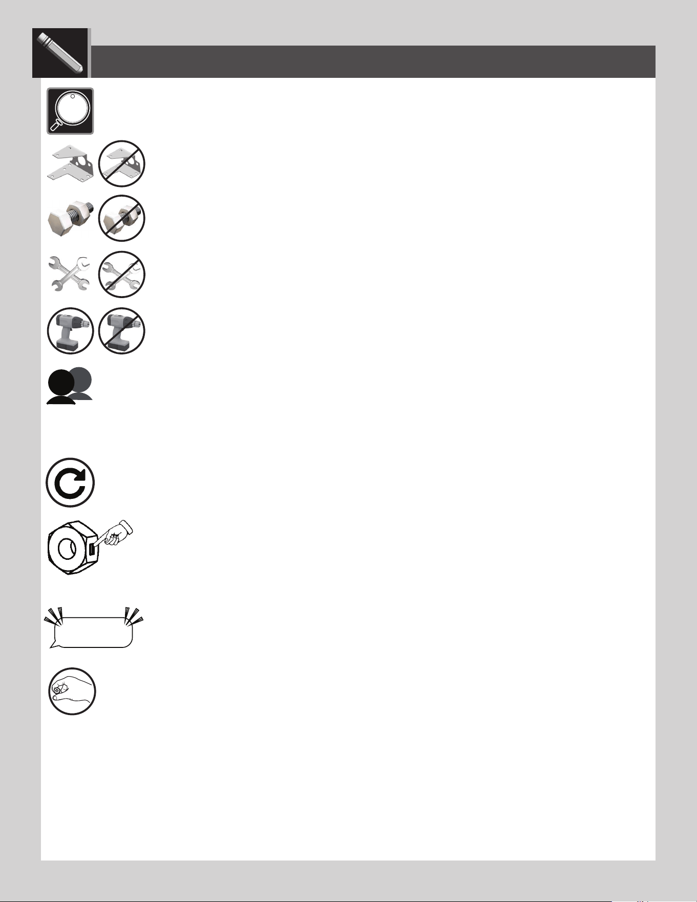
• Indicates the parts (or no parts) required for a section.
• Indique les pièces (ou aucune pièce) à utiliser pour une section.
• Indica las piezas (o ninguna pieza) que se usarán en una sección.
• Indicates special heed should be taken when reading.
• Indique qu’une attention spéciale doit être portée à la lecture.
• Indica que uno debe prestar atención al leer.
• Indicates the tools (or no tools) to be used for a section.
• Indique les outils (ou aucun outil) à utiliser pour une section.
• Indica las herramientas (o ninguna herramienta) que se utilizarán para una sección.
• Indicates the number of adults required to perform a specifi c step, e.g., 2, 3, 4, etc. You may be able to do certain steps by
yourself but, for safety reasons, it’s best to have two or more adults. And...it’s always easier with one or two helpers.
• Indique le nombre d’adultes requis pour e ectuer une étape spécifi que, p. ex., 2, 3, 4, etc. Il est possible de réaliser
certaines étapes seul mais, pour des raisons de sécurité, il est préférible d’être au moins deux adultes. Et... c’est toujours plus facile avec un assistant ou deux.
• Indica el número de adultos requeridos para realizar un paso específi co, p.ej., 2, 3, 4, etc. Es posible realizar unos pasos
solo mas, por razones de seguridad, es mejor tener dos adultos o más. Y... siempre es más fácil con un ayudante o dos.
• Indicates to repeat a step or an action.
• Indique de répéter une étape ou une action.
• Indica repetir un paso o una acción.
• Indicates a specifi c step is harder to perform.
• Indique qu’une étape spécifi que est plus di cile à exécuter.
• Indica que un paso específi co es más difícil de realizar.
• Indicates the hardware (no new hardware) required for a specifi c page or section.
• Indique la quincaillerie (ou aucune nouvelle quincaillerie) n’est requis pour une page précise.
• Indica el herraje (que no se necesita nuevo herraje) para una página específi ca.
• Indicates to use/not use an electric drill for a specifi c step.
• Indique quand utiliser une/que ne pas utiliser de perceuse électrique pour une étape précise.
• Indica la utilización de/que no utilizar un taladro eléctrico para un paso específi co.
ICON LEGEND / LÉGENDE DES ICÔNES / LEYENDA DE ÍCONOS
• Indicates the use of a centerlock nut. A nut with this marking will require some e ort to tighten. This
hardware was designed with this feature in order to prevent loosening later.
• Cette image indique l’usage d’un écrou de blocage central. Un écrou avec ce marquage requerra plus
d’e ort pour le serrer. Cet écrou a été conçu avec cette fonction afi n d’empêcher son desserrage plus tard.
• Indica el uso de una tuerca de bloque central. Una tuerca con esta marca requerirá un poco de esfuerzo para
apretarlo. Esta tuerca fue diseñada con esta característica con el fi n de evitar su afl ojamiento más tarde.
“$#@*%!”
LIFETIME
®
• Indicates that one should only hand-tighten the hardware until instructed otherwise.
• Indique qu’il ne faut serrer la quincaillerie qu’à la main jusqu’à ce que l’on reçoive des instructions contraires.
• Indica que sólo se debe apretar a mano el herraje hasta que indique lo contrario.

5
English:
• Failure to follow these warnings may result in serious injury or property damage and will void warranty.
• To ensure safety, do not attempt to assemble this product without following the instructions carefully.
• Consult all local building codes to verify if the shed requires a building permit.
• Verify the platform foundation is completely level before assembling the shed.
• Be aware that plastic pieces can be damaged by overtightening the screws. To avoid damage, we strongly recommend the use of a drill
with a low torque setting. A #2 Phillips screwdriver may also be used.
• Three capable adults are required for assembly.
• All who participate in the assembly process should wear safety glasses throughout the assembly.
• If using a ladder during assembly, use extreme caution.
• In heavy snowfall areas, we recommend removing snow from the roof. Remove the snow from the roof when the depth of snow
equals the length of your hand.
• Do not use or store hot objects near the product.
• Proper and complete assembly are essential to reduce the risk of accident or injury.
• When drilling through metal, beware of burrs, shavings and other sharp edges.
• During and after assembly, do not slide or lift the shed by pushing up on the roof. Move the shed by pushing on the corner panels only.
•
Failure to anchor the shed may result in property damage and/or personal injury. The last section, Shed Anchoring, in this manual shows the
hardware you will need to complete the anchoring. You can fi nd the hardware at your local hardware store.
• Do not stand on the roof.
• Most injuries are caused by misuse and/or not following instructions. Use caution when using this product.
Français :
• Ne pas suivre ces avertissements peut entraîner des blessures graves ou des dommages à la propriété et annulera la garantie.
• Afi n d’assurer la sécurité, ne pas tenter d’assembler ce produit sans suivre attentivement les instructions.
• Consulter tous les codes du bâtiment afi n de vérifi er si l’abri nécessite un permis de construire.
• Vérifi er que la fondation de la plate-forme est complètement à niveau avant l’assemblage de l’abri.
• Ne pas oublier que les pièces de plastique peuvent être endommagées en serrant trop les vis. Afi n d’éviter les dommages, nous
recommandons fortement l’utilisation d’une perceuse à faible couple. Un tournevis cruciforme nº 2 peut aussi être utilisé.
• Trois adultes en bonne condition physique sont nécessaires pour l’assemblage.
• Tout ceux qui participent au processus de l’assemblage doivent porter des lunettes de sécurité tout au long de l’assemblage.
• Si une échelle est utilisée pour l’assemblage, il faut être extrêmement prudent.
• Dans les zones de fortes tombées de neige, il est recommandé de dégager le toit. Enlever la neige du toit quand la profondeur est égale
à la longueur de la main.
• Ne pas utiliser ou entreposer des objets très chauds près de ce produit.
• Un bon assemblage complet est nécessaire pour réduire le risque d’accident ou de blessure.
• En perçant le métal, faire attention aux bavures, copeaux et autre bords aiguisés.
• Pendant et après l’assemblage, ne pas faire glisser ou soulever l’abri en poussant le toit vers le haut. Déplacer l’abri en poussant les
panneaux muraux angulaires seulement.
• Si vous n’ancrez pas votre abri, des dommages à la propriété et/ou des blessures peuvent en résulter. La dernière section, Ancrage de l’abri, de
ce manuel indique les matériaux nécessaires pour l’ancrage. Les matériaux se trouvent dans la quincaillerie locale.
• Ne pas monter sur le toit.
• La majorité des blessures sont causées par une mauvaise utilisation et/ou le non suivi des instructions. Étre prudent en utilisant ce produit.
Español:
• No seguir estas advertencias puede resultar en lesiones graves o daños a la propiedad y anulará la garantía.
• A fi n de garantizar la seguridad, no intentar ensamblar este producto sin seguir cuidadosamente las instrucciones.
• Consultar todos los códigos de construcción locales para verifi car si el cobertizo requiere un permiso de construcción.
• Verifi car que el concreto de la plataforma esté nivelado completamente antes de ensamblar el cobertizo.
• Tener en cuenta que las piezas de plástico pueden dañarse si los tornillos se aprietan de más. A fi n de evitar daños, lo exhortamos a que
use un taladro con función de torque bajo. También puede usarse un desatornillador Phillips no. 2.
• Se necesitan tres adultos para el ensamble.
• Todos los que participen en el proceso de ensamble debe usar anteojos de seguridad durante todo el ensamble.
• Si se usa una escalera durante el ensamblado, es preciso tener cuidado.
• En áreas de nevadas fuertes, recomendamos retirar la nieve del techo. Quitar la nieve del tejado cuando la profundidad de ella es igual
a la longitud de la mano.
• No usar ni guardar objetos calientes cerca del producto.
• El ensamblaje correcto y completo son esenciales para reducir el riesgo de accidente o lesión.
• Al perforar metal, tenga cuidado las rebabas, virutas y otros bordes afi lados.
• Durante y después del ensamblaje, no deslizar ni levantar el cobertizo para empujar en el tejado. Mover el cobertizo para empujar los
paneles murales angulares solamente.
• No anclar el cobertizo puede resultar en daños a la propiedad y/o en lesiones personales. La última sección, Anclaje de el cobertizo, en este
manual muestra el herraje necesaria para terminar el anclaje. Se encuentra el herraje en la ferretería local.
• No pararse en el techo.
• La mayoría de las lesiones suceden a causa del mal uso y/o por no seguir las instrucciones. Tener precaución al usar este producto.
WARNINGS & NOTICES / AVERTISSEMENTS ET AVIS / ADVERTENCIAS Y AVISOS
6
PLATFORM CONSTRUCTION / CONSTRUCTION DE LA PLATE-FORME / CONSTRUCCIÓN DE LA PLATAFORMA
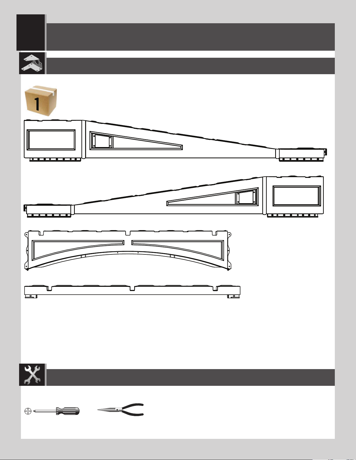
1
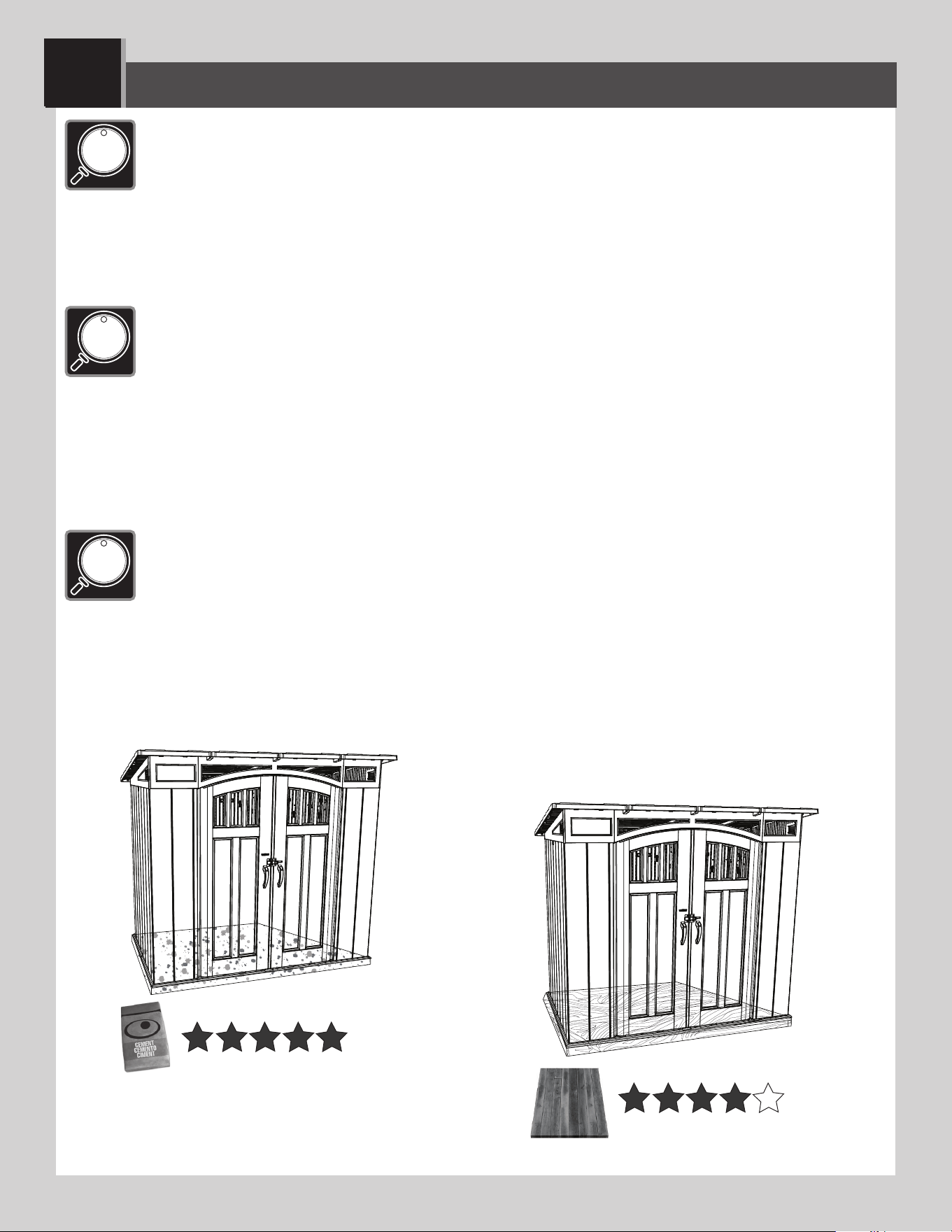
• You must provide a platform on which to assemble your shed. Proper building permit documentation may be
required in your neighborhood. Consult all local building codes prior to assembling the shed. Before beginning
assembly, you must pour or construct a platform. There are two types:
• Concrete
• Wood Platform
Select the type, but know the surface must be leveled and fl at before installation. If the surface is not properly leveled and fl at,
the shed will not assemble correctly. Proper surface leveling will save you time in the long run, so please do not ignore this
step. We recommend a Concrete platform. It will be the most durable and long-lasting choice. The platform you choose must be built above ground in order to avoid water pooling
inside the shed. All lumber must be rated for outdoor use!
• Il faut construire une plate-forme sur laquelle vous devez assembler votre abri. Il est possible que votre quartier
exige une documentation visant les permis de construire. Consultez tous les codes du bâtiment locaux, ainsi
que les décrets des villes et comtés, pour vérifi er que la construction de l’abri extérieur n’exige pas un permis de
construire. Avant de commencer l’assemblage, il faut couler ou construire une plate-forme. Il y à deux styles :
• Béton
• Plat-forme en bois
Sélectionnez le style, mais sachez que la surface d’installation doit être de niveau et plate. Si la surface n’est pas
correctement de niveau et plate, l’assemblage de l’abri ne se fera pas correctement. Vous gagnerez du temps sur le long
terme grâce à une surface bien de niveau, ne négligez donc pas cette étape. Nous recommandons une plate-forme en Béton. Ce choix sera le plus
durable. La plate-forme que vous choisissez doit être construite au-dessus du sol afi n d’éviter l’accumulation d’eau à l’intérieur de l’abri. Tous le bois d’oeuvre doit être approuvé
pour l’usage à l’extérieur !
• Es preciso construir una plataforma sobre la cual usted debe ensamblar su caseta. Puede suceder que en su
vecindario se requiera la documentación apropiada de un permiso de construcción. Consulte todos los códigos
locales de construcción y los reglamentos de la ciudad y el municipio para asegurarse de que la construcción
de el cobertizo no requiere un permiso de construcción. Antes de comenzar el ensamblaje, es necesario verter o
construir una plataforma. Hay dos clases:
• Concreto
• Platforma de madera
Seleccione la clase, mas sepa que la superfi cie debe estar nivelada y plana antes de comenzar el armado. Si la superfi cie
no está nivelada y plana de manera adecuada, el caseta no podrá armarse correctamente. La nivelación de la superfi cie le
ahorrará tiempo de trabajo, por lo tanto, le pedimos que no ignore este paso. Recomendamos una plataforma hecha de concreto. Será la elección
más perdurable. La plataforma debe ser construida arriba del suelo para evitar el afl ujo de agua dentro de el cobertizo. ¡Toda la madera debe estar clasifi cada para el uso externo!
7
X SECTION 1 (CONTINUED) / SECTION 1 (SUITE) / SECCIÓN 1 (CONTINUACIÓN)
1 yd
3
(≈0,77 m
3
)
1
CONCRETE REQUIRED / BÉTON REQUIS / CONCRETO REQUERIDO
CONCRETE PLATFORM / PLATE-FORME EN BÉTON / PLATAFORMA DE CONCRETO
1.1
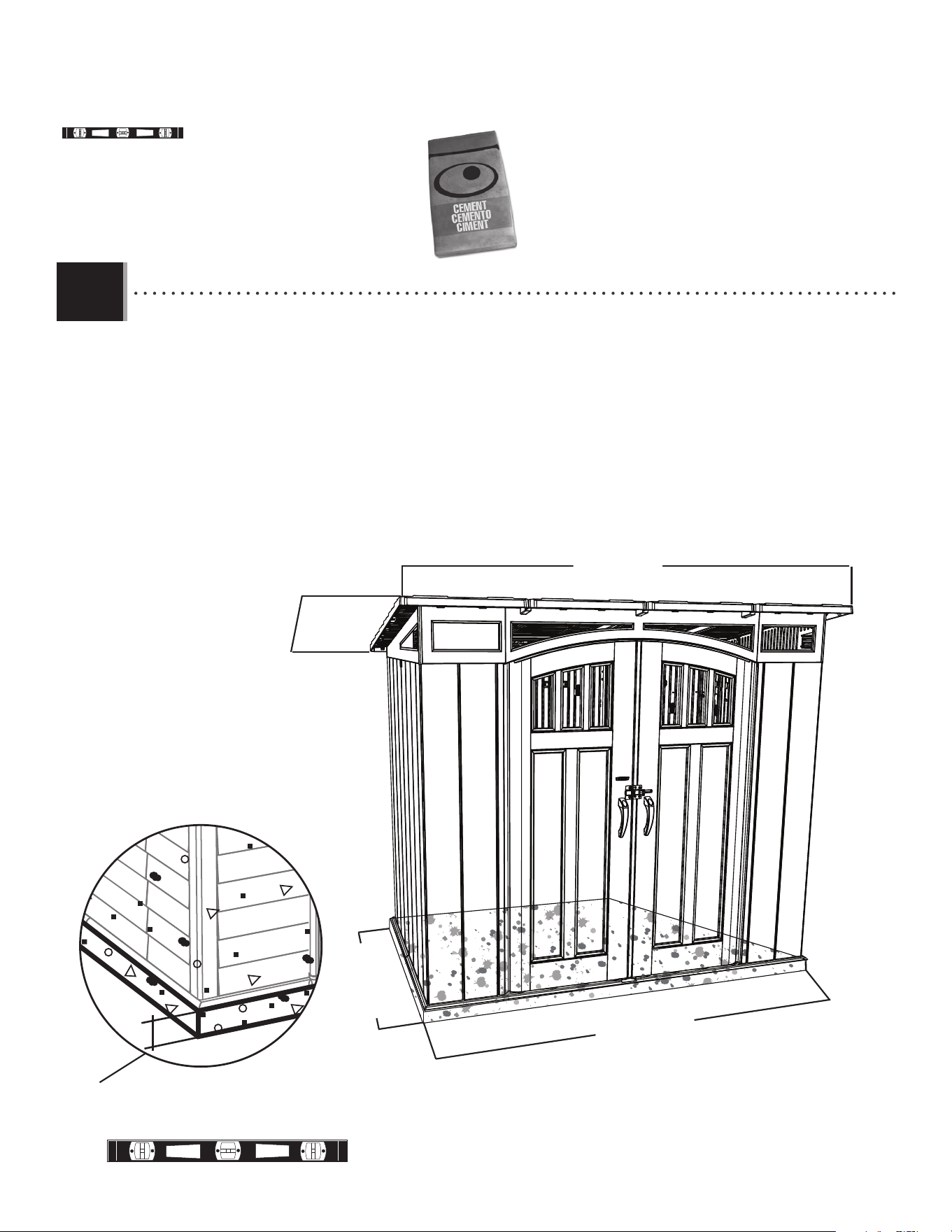
• The concrete should be approximately 4" (≈10,2 cm) thick. The actual dimensions of the shed, at its widest
and longest points, are 100" x 65" (≈2,54 m x ≈1,65 m). Ensure you select a site that will accommodate these
measurements. The fl oor dimensions are a bit smaller than those of the roof; therefore, you will need to builld a level surface of 94" x 58" (≈2,38 m x ≈1,47
m).
• Le béton doit être un épaisseur de ≈10,2 cm (4”). Les dimensions réelles de votre abri, aux points les plus large
et long, sont ≈2,54 m x ≈1,65 m (100" x 65"). Assurez-vous de sélectionner un site qui accommodera ces
dimensions. Les dimensions du plancher de votre abri sont plus petites que le toit; ensuite, il faut créer une surface horizontal de ≈2,38 m x ≈1,47 m (94" x
58").
• El concreto debe tener, por lo menos, ≈10,2 cm (4”) de espesor. Las dimensiones reales de el cobertizo, a
sus puntos más ancho y largo, son ≈2,54 m x ≈1,65 m (100" x 65"). Asegúrese de seleccionar un sitio que
acomodará estas medidas. Las dimensiones del piso de el cobertizo son más pequeñas que el tejado; entonces, necesitará crear una superfi cie nivel
de ≈2,38 m x ≈1,47 m (94" x 58").
4" (≈10,2 cm)
100" (≈2,54 m)
65" (≈1,65 m)
58" (≈1,47 m)
94" (≈2,38 m)
8
X SECTION 1 (CONTINUED) / SECTION 1 (SUITE) / SECCIÓN 1 (CONTINUACIÓN)
1
WOOD PLATFORM / PLATE-FORME EN BOIS / PLATAFORMA DE MADERA
1.2
WOOD REQUIRED / BOIS REQUIS / MADERA REQUERIDA
DA
58" (≈1,47 m)
94" (≈2,38 m)
65" (≈1,65 m)
100" (≈2,54 m)
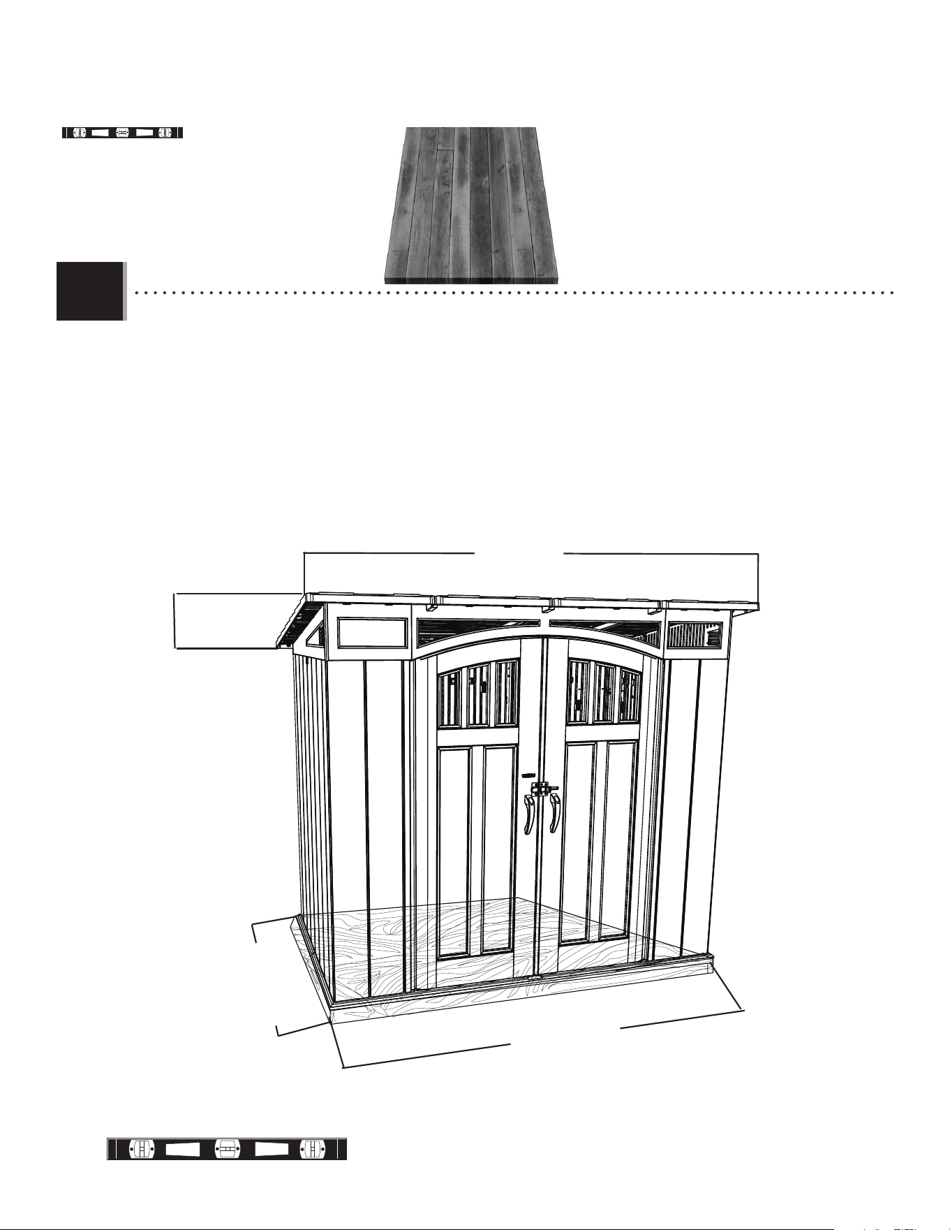
• All lumber must be rated for outdoor use! The actual dimensions of the shed, at its widest and longest points, are 100" x 65"
(≈2,54 m x ≈1,65 m). Ensure you select a site that will accommodate these measurements. The fl oor dimensions are a bit
smaller than those of the roof; therefore, you will need to builld a level surface of 94" x 58" (≈2,38 m x ≈1,47 m).
• Tous le bois d’oeuvre doit être approuvé pour l’usage à l’extérieur ! Les dimensions réelles de votre abri, aux points les plus large et long,
sont ≈2,54 m x ≈1,65 m (100" x 65"). Assurez-vous de sélectionner un site qui accommodera ces dimensions. Les
dimensions du plancher de votre abri sont plus petites que le toit; ensuite, il faut créer une surface horizontal de ≈2,38 m x ≈1,47 m (94" x 58")
• ¡Toda la madera debe estar clasifi cada para el uso externo! Las dimensiones reales de el cobertizo, a sus puntos más ancho y largo,
son ≈2,54 m x ≈1,65 m (100" x 65"). Asegúrese de seleccionar un sito que acomodará estas medidas. Las
dimensiones del piso de el cobertizo son más pequeñas que el tejado; entonces, necesitará crear una superfi cie nivel de ≈2,38 m x ≈1,47 m (94" x 58")
9
X SECTION 1 (CONTINUED) / SECTION 1 (SUITE) / SECCIÓN 1 (CONTINUACIÓN)
x8
1
TOOLS, PARTS, AND HARDWARE REQUIRED / OUTILS, PIÈCES, ET QUINCAILLERIE REQUIS/ INSTRUMENTAL, PIEZAS, Y ACCESORIOS REQUERIDOS
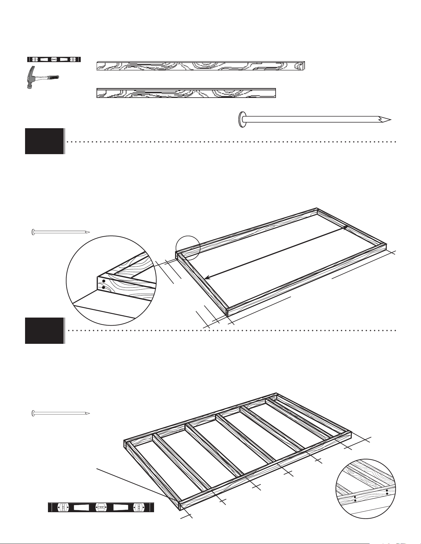
• Ensure all lumber is treated and approved for outdoor use. Build frame to 94” x 58” (≈2,38 m x ≈1,47 m) (outside
dimensions). You can also use the plywood as a fl at surface when building this frame.
• Vérifi ez que votre bois d’œuvre à été traité et approuvé pour l’utilisation à l’extérieur. Contruisez un cadre de
≈2,38 m x ≈1,47 m (94” x 58”) (dimensions extérieures). Vous pouvez aussi utiliser le contreplaqué comme une surface plate pendant l’assemblage
de ce cadre.
• Asegure que use madera tratada y aprobada para el uso externo. Construye el armazón a ≈2,38 m x
≈1,47 m (94” x 58”) (dimensiones exteriores). Se puede también usar el contrachapado como una
superfi cie plana al ensemblar este armazón.
• To ensure studs are in the correct location for nailing plywood in the next step, start measuring from the corner 16”
(≈40,1 cm), and then measure from center to center.
• Pour être sûr d’avoir assez de montant pour clouer le contreplaqué dans le prochaine étape, commencez à mesurer
à partir de cette montant ≈40,1 cm (16”) vers le centre du deuxième montant. Ensuite, mesurez de centre à centre
pour les montants restants.
• Para asegurarse que los montantes están en las ubicaciones correctas para el contrachapado en el paso siguiente,
comience a medir desde el borde del montante hasta el centro del próximo montante ≈40,1 cm (16”). Luego, tome
la medida de centro a centro en los montantes restantes.
WOOD PLATFORM / PLATE-FORME EN BOIS/ PLATAFORMA DE MADERA
1.2.1
1.2.2
94" (≈2,38 m)
58" (≈1,47 m)
55" (≈1,38 m)
x20
16” (≈40,1 cm)
16” (≈40,1 cm)
16” (≈40,1 cm)
16” (≈40,1 cm)
16” (≈40,1 cm)
Start Here
Commencez ici
Comience aquí
2" x 4" x 94" (≈5,1 cm x ≈10,2 cm x ≈2,38 m) (x2)
2" x 4" x 55" (≈5,1 cm x ≈10,2 cm x ≈1,38 m) (x7)
16d 3 1/2” (≈16 mm diam. x ≈8,89 cm) (x28)
10
X SECTION 1 (CONTINUED) / SECTION 1 (SUITE) / SECCIÓN 1 (CONTINUACIÓN)
1
• Drainage Holes
• Trous de drainage
• Agujeros para el drenaje
TOOLS, PARTS, AND HARDWARE REQUIRED / OUTILS, PIÈCES, ET QUINCAILLERIE REQUIS / INSTRUMENTAL, PIEZAS, Y ACCESORIOS REQUERIDOS
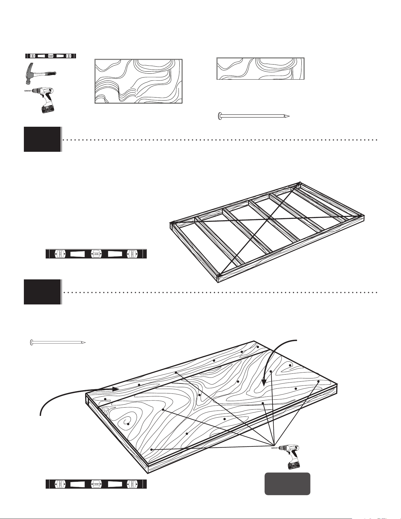
• Square the frame, measuring from corner to corner. Measurement A & B should be about the same length.
• Carrez le cadre en mesurant d’angle à angle. La mesure « A » et « B » doivent être à peu près la même longeur.
• Cuadre el armazón midiendo de esquina a esquina. La medida «A» y «B» deben ser approximadamente el mismo largo.
• Using nails, fasten the plywood to the frame. Then, drill 5/16” holes for drainage.
• En utilisant des clous, attachez bien le contreplaqué au cadre. Ensuite, percez des trous de 8 mm pour le
drainage.
• Usando unos clavos, sujete el contrachapado al armazón. Entonces, taladre agujeros de 8 mm para el drenaje.
1.2.3
1.2.4
A
B
10” x 93 1/2” x 3/4”
(≈25,4 cm x ≈2,38 m x ≈19,1 mm)
48” x 93 1/2” x 3/4”
(≈1,22 cm x ≈2,38 m x ≈19,1 mm)
x42
x18!
8d 2 1/2” (≈8 mm diam. x ≈6,35 cm) (x42)
48” x 94” x 3/4”
(≈1,22 m x ≈2,38 m x ≈19,1 mm) (x1)
10” x 94” x 3/4”
(≈25,4 cm x ≈2,38 m x ≈19,1 mm) (x1)
11
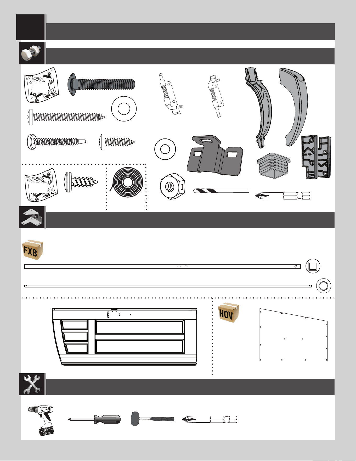
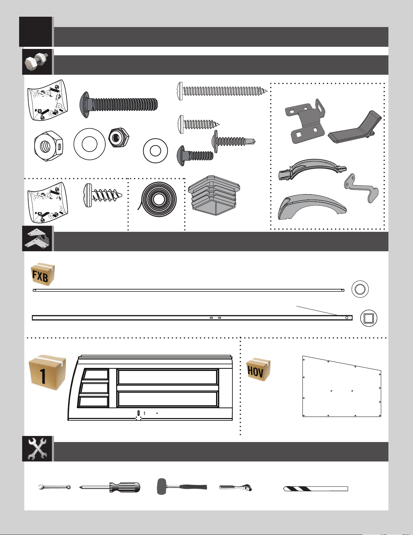
BDJ (x1)
EOY (x1)
AAB (x2)
AEB (x2)
AEE (x3)
ACH (x2)
FXA
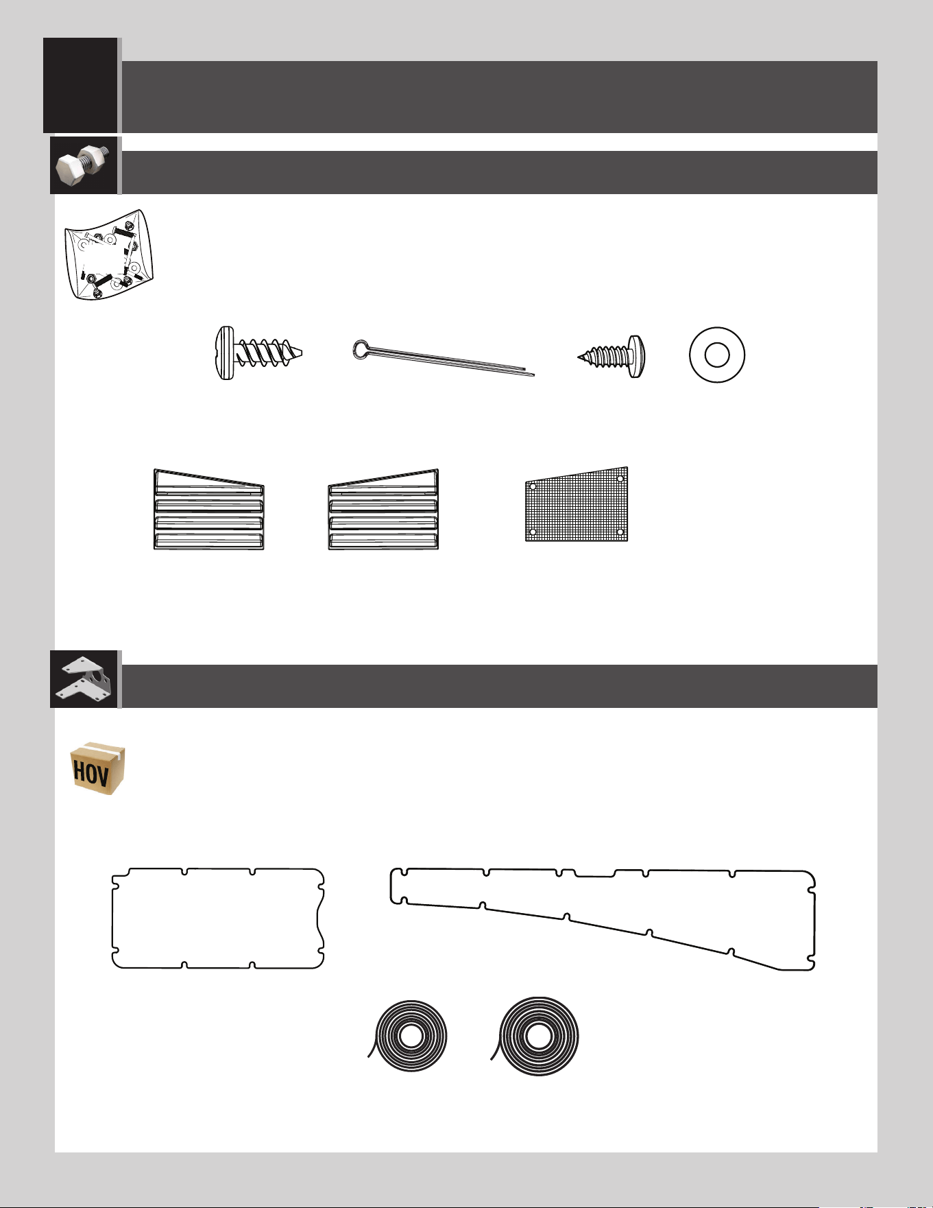
Metal parts / Pièces en métal / Piezas de metal
Plastic parts / Pièces en plastique / Piezas de plástico
PARTS REQUIRED / PIÈCES REQUISES / PIEZAS REQUERIDAS
HARDWARE REQUIRED / QUINCAILLERIE REQUISE / HERRAJE REQUERIDO
BYR (x1)
DHN (x1)
FVW(x1)
EDW (x1)
ADC (x1)*
BBH (x1)
ENP (x2)
DGS (x1)
DGR (x1)
Upper / Supérieur / Superior
Lower / Inférieur / Inferior
BYS (x1)
BYZ (x2)
ADW (x1)
ENO (x4)
DHL
ADZ (x14)
EPH (x1)
LEFT DOOR ASSEMBLY / ASSEMBLAGE DE LA PORTE GAUCHE / ENSAMBLAJE DE LA PUERTA IZQUIERDA
2
GHO (x1)
ADC (x1)
TOOLS REQUIRED / OUTILS REQUIS / INSTRUMENTAL REQUERIDO
(Not included—unless otherwise indicated*) / (Non inclus — sauf indication contraire*) / (No incluido, salvo indicación contraria*)
12
TOOLS AND HARDWARE REQUIRED / OUTILS ET QUINCAILLERIE REQUIS / INSTRUMENTAL Y HERRAJE REQUERIDOS
X SECTION 2 (CONTINUED) / SECTION 2 (SUITE) / SECCIÓN 2 (CONTINUACIÓN)
EDW
BBH
BDJ
• Align these holes
• Aligner ces trous
• Alinear estos agujeros
• Holes
• Trous
• Agujeros
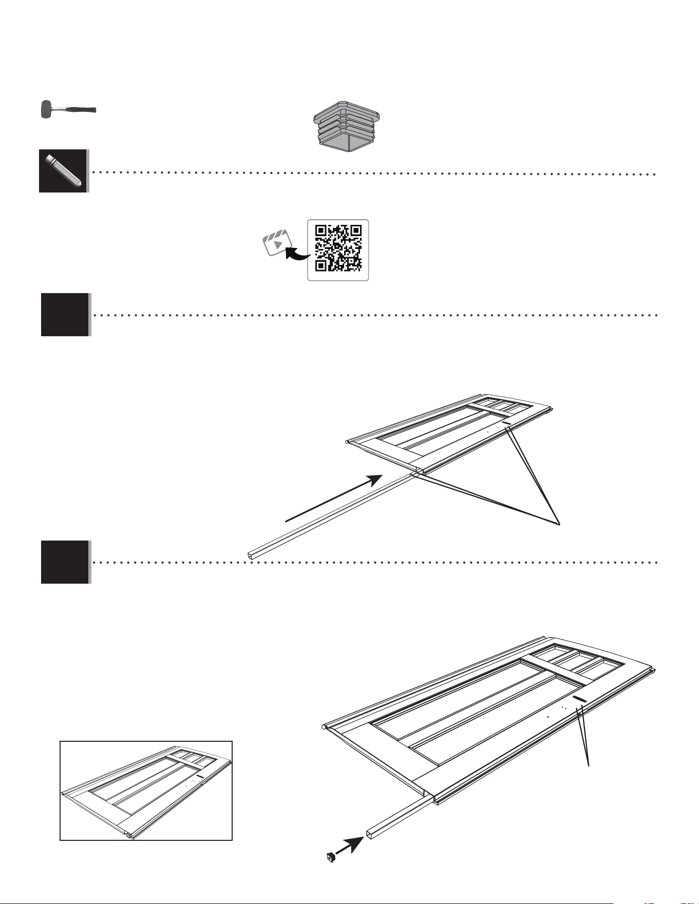
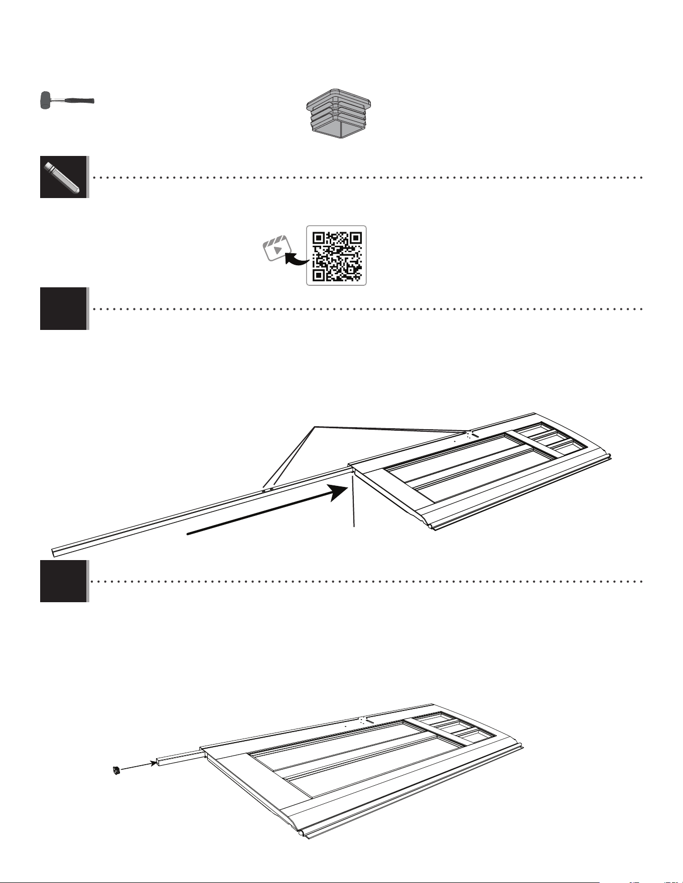
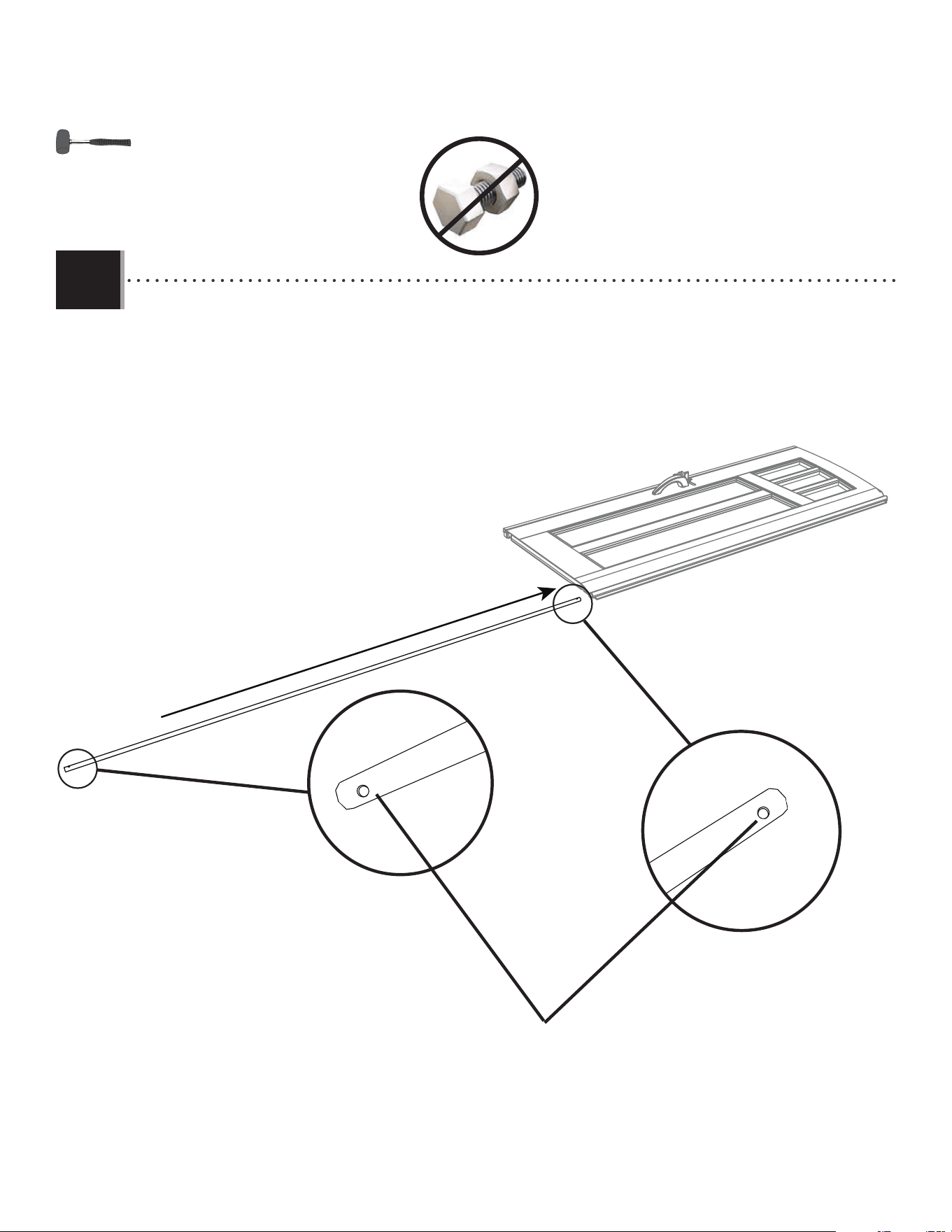
• Slide a square tube (EDW) into the square hole at the bottom of the left door (BDJ) until about 6" (≈15 cm) of the tube hang
out of the hole.
• Faire glisser un tube carré (EDW) dans le trou carré au bord inférieur de la porte gauche (BDJ) jusqu’à ce que environ ≈15 cm
(6 po) étendent du trou.
• Deslizar un tubo cuadrado (EDW) en el orifi cio cuadrado a la parte inferior de la puerta izquierda (BDJ) hasta que unos ≈15 cm
(6 in) cuelguen del agujero.
• Insert the end cap (BBH) into the end of the square tube and continue inserting the tube until it is fl ush with the
bottom of the door. Align the two holes in the tube with the two holes in the door. If necessary, gently tap with a
rubber mallet.
• Insérer un capuchon (BBH) dans l’extrémité du tube carré et continuer à insérer le
tube jusqu’à ce qu’il soit à ras del borde inférieur de la porte. Aligner les deux
trous dans le tube avec les deux trous dans la porte. Si besoin, frapper
soigneusement avec un maillet en caoutchouc.
• Insertar un tapón (BBH) en el extremo del tubo cuadrado y continuar
a insertar el tubo hasta que esté al ras del borde inferior
de la puerta. Alinear los dos agujeros en el tube
con ellos en la puerta. Si es necesario, golpear
cuidadosamente con un mazo de goma.
2.1
2.2
BBH (x1)
http://go.lifetime.com/compactmodernshed-section2
LIFETIME
®
• In case of troubles with this section, scan the QR code below to view a video on its assembly.
• En cas d’avoir des problèmes avec cette section, scanner le code QR en dessous pour voir un vidéo de l’assemblage.
• En caso de tener problemas con esta sección, escanear el código QR debajo para ver un video del ensamblaje.
13
TOOLS AND HARDWARE REQUIRED / OUTILS ET QUINCAILLERIE REQUIS / INSTRUMENTAL Y HERRAJE REQUERIDOS
X SECTION 2 (CONTINUED) / SECTION 2 (SUITE) / SECCIÓN 2 (CONTINUACIÓN)
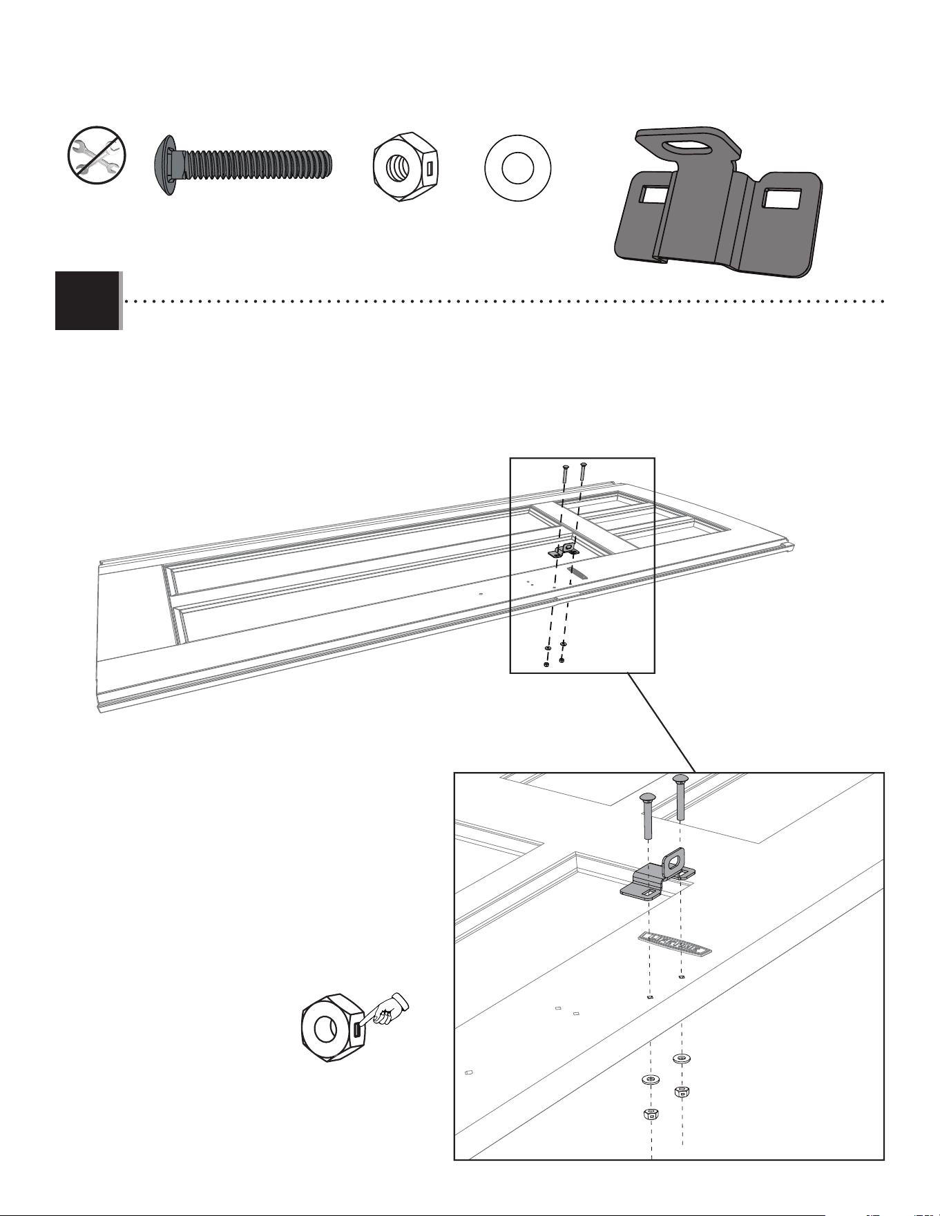
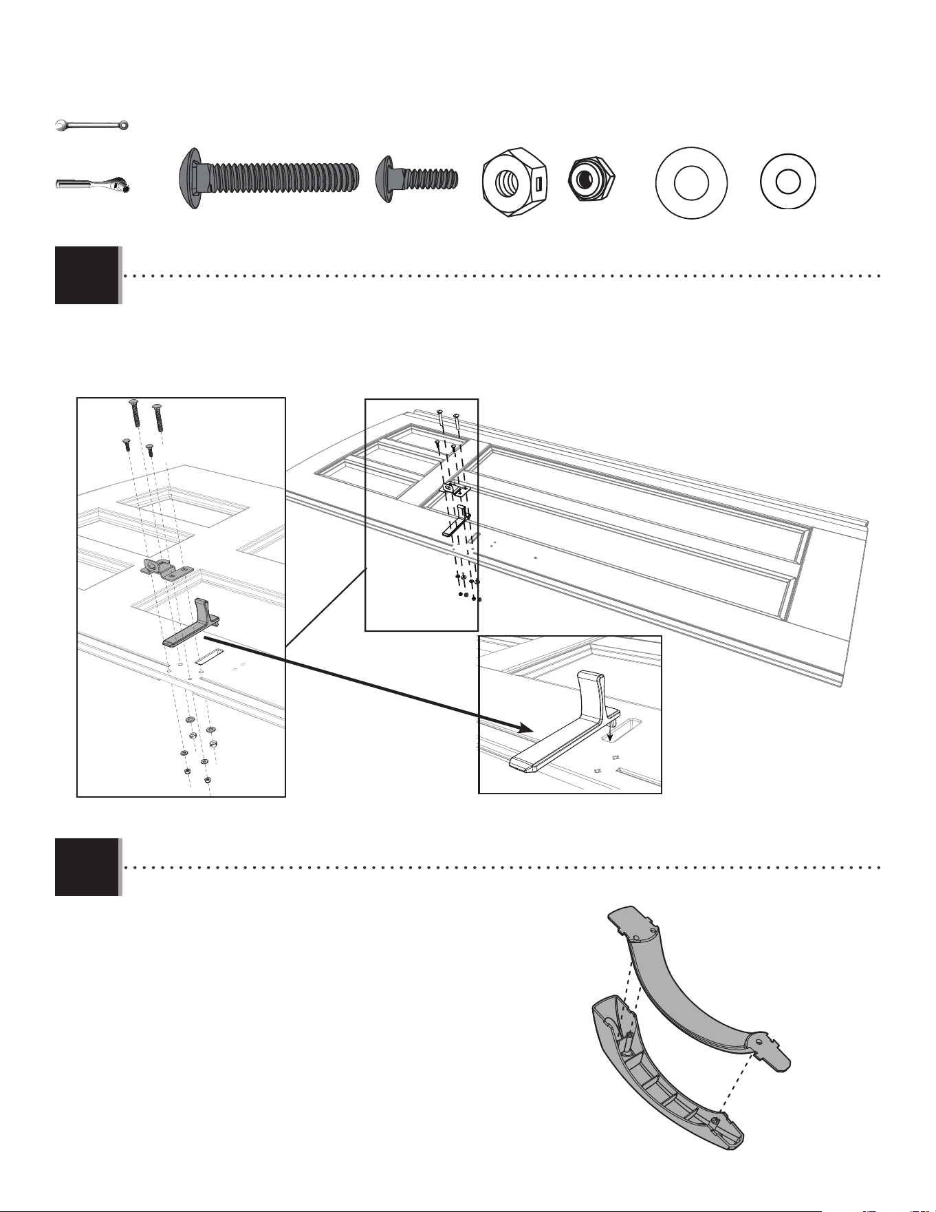
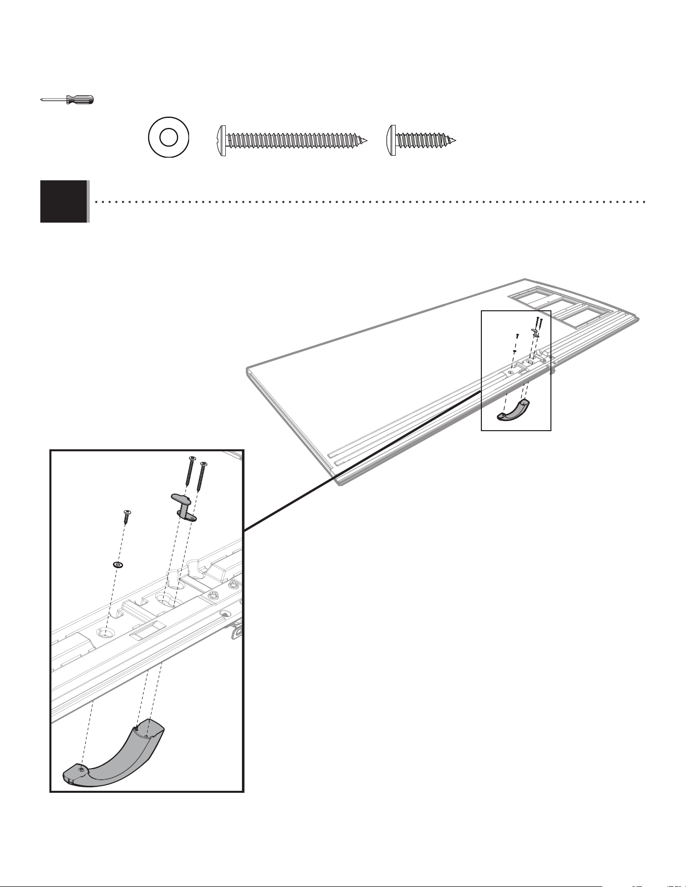
• Attach the door latch bracket (EOY) to the door using the hardware indicated. Do not overtighten.
• Attacher le support du loquet de la porte (EOY) à la porte à l’aide de la quincaillerie indiquée. Ne pas trop serrer.
• Fijar el soporte del cerrojo de la puerte (EOY) a la puerta usando el herraje indicado. No apretar demasiado.
2.3
AAB
AEB
AAB
AEB
EOY
ACH
ACH
EOY (x1)
AAB (x2)
AEB (x2)
ACH (x2)
14
TOOLS AND HARDWARE REQUIRED / OUTILS ET QUINCAILLERIE REQUIS / INSTRUMENTAL Y HERRAJE REQUERIDOS
X SECTION 2 (CONTINUED) / SECTION 2 (SUITE) / SECCIÓN 2 (CONTINUACIÓN)
2.4
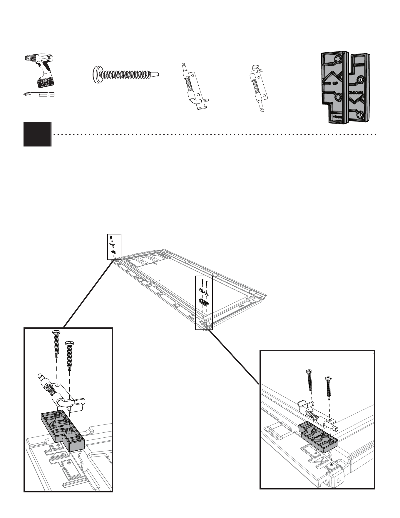
• Flip the door over. Secure the upper and lower latches (DGS and DGR) with a spacer (ENP) to the door using two (2) screws (ENO)
each. The spacers are labelled “UP” and “DOWN” for correct placement. The latches should move freely. If not, loosen the screws
a bit.
• Retournez la porte. Attachez les loquets supérieur et inférieur (DGS et DGR) avec une cale d’espacement (ENP) à la porte à l’aide
de deux (2)vis (ENO) pour chacun. Les cales d’espacement sont marquées «HAUT» et «BAS» pour assurer un
positionnement correct. Les loquets doivent pouvoir bouger librement. Si ce n’est pas le cas, desserrez les vis un
peu.
• Voltee la puerta. Asegure a la puerta los pestillos superior e inferior (DGS y DGR) con un espaciador (ENP) usando dos (2) tornillos
(ENO) para cada uno. Los espaciadores están etiquetados como “SUPERIOR” e “INFERIOR” para una colocación
correcta. Los pestillos deben moverse libremente. Si no es así, afl oje un poco los tornillos.
ENP
ENO
ENO
ENO
ENO
ENP
ENO (x4)
DGS(x1)
DGR (x1)
Upper / Supérieur / Superior
Lower / Inférieur / Inferior
ADC
DGR
DGS
ENP (x2)
15
TOOLS AND HARDWARE REQUIRED / OUTILS ET QUINCAILLERIE REQUIS / INSTRUMENTAL Y HERRAJE REQUERIDOS
X SECTION 2 (CONTINUED) / SECTION 2 (SUITE) / SECCIÓN 2 (CONTINUACIÓN)
2.5
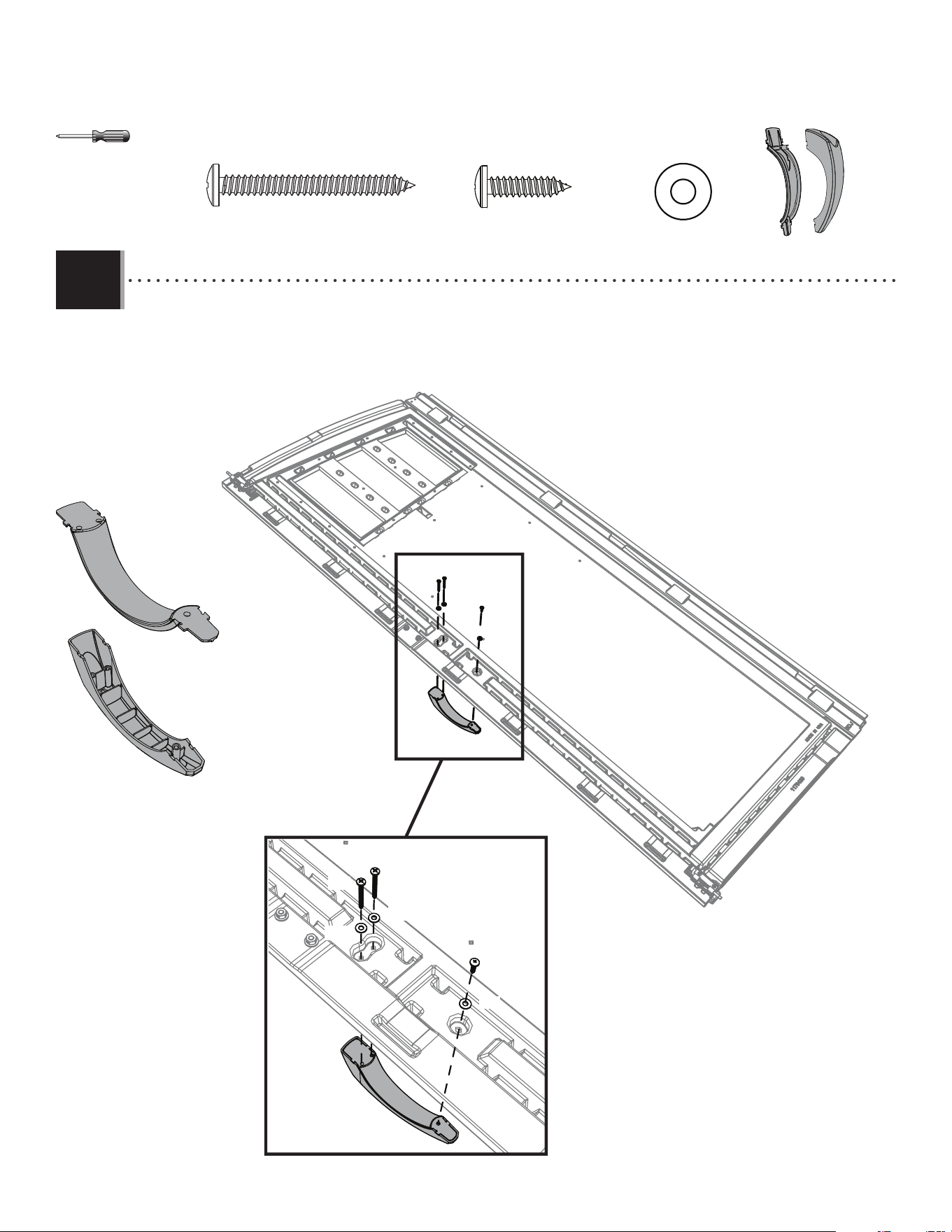
• Attach the front and rear handle pieces (BYS and BYR) together. Secure the handle to the door using the hardware
indicated.
• Attacher les parties avant et arrière de la poignée (BYS et BYR). Bien fi xer la poignée à la porte à l’aide de la quincaillerie
indiquée.
• Conectar las piezas delantera y trasera del picaporte (BYS y BYR). Fijar bien el picaporte a la puerta usando el herraje indicado.
BYS
BYR
BYZ (x2)
BYZ
BYZ
ADW
AEE
AEE
AEE
AEE (x3)
ADW (x1)
BYR (x1)
BYS (x1)

16
TOOLS AND HARDWARE REQUIRED / OUTILS ET QUINCAILLERIE REQUIS / INSTRUMENTAL Y HERRAJE REQUERIDOS
X SECTION 2 (CONTINUED) / SECTION 2 (SUITE) / SECCIÓN 2 (CONTINUACIÓN)
2.6
• Slide a hinge tube (FVW) into the hole at the bottom of the door. If necessary, use a rubber mallet to gently tap the tube into place. This tube
has a hole at both ends.
• Faire glisser un tube de charnière (FVW) dans le trou au fond de la porte. Si besoin, employer un maillet en caoutchouc pour taper le tube en
place. Ce tube a une trou à chaque extrémité.
• Deslizar un tubo de bisagra (FVW) en el orifi cio al fondo de la puerta. Si es necesario, usar un mazo de goma para golpear el tube en su lugar.
Este tubo tiene una agujero a cada extremo.
FVW
• Holes
• Trous
• Agujeros
17
TOOLS AND HARDWARE REQUIRED / OUTILS ET QUINCAILLERIE REQUIS / INSTRUMENTAL Y HERRAJE REQUERIDOS
X SECTION 2 (CONTINUED) / SECTION 2 (SUITE) / SECCIÓN 2 (CONTINUACIÓN)
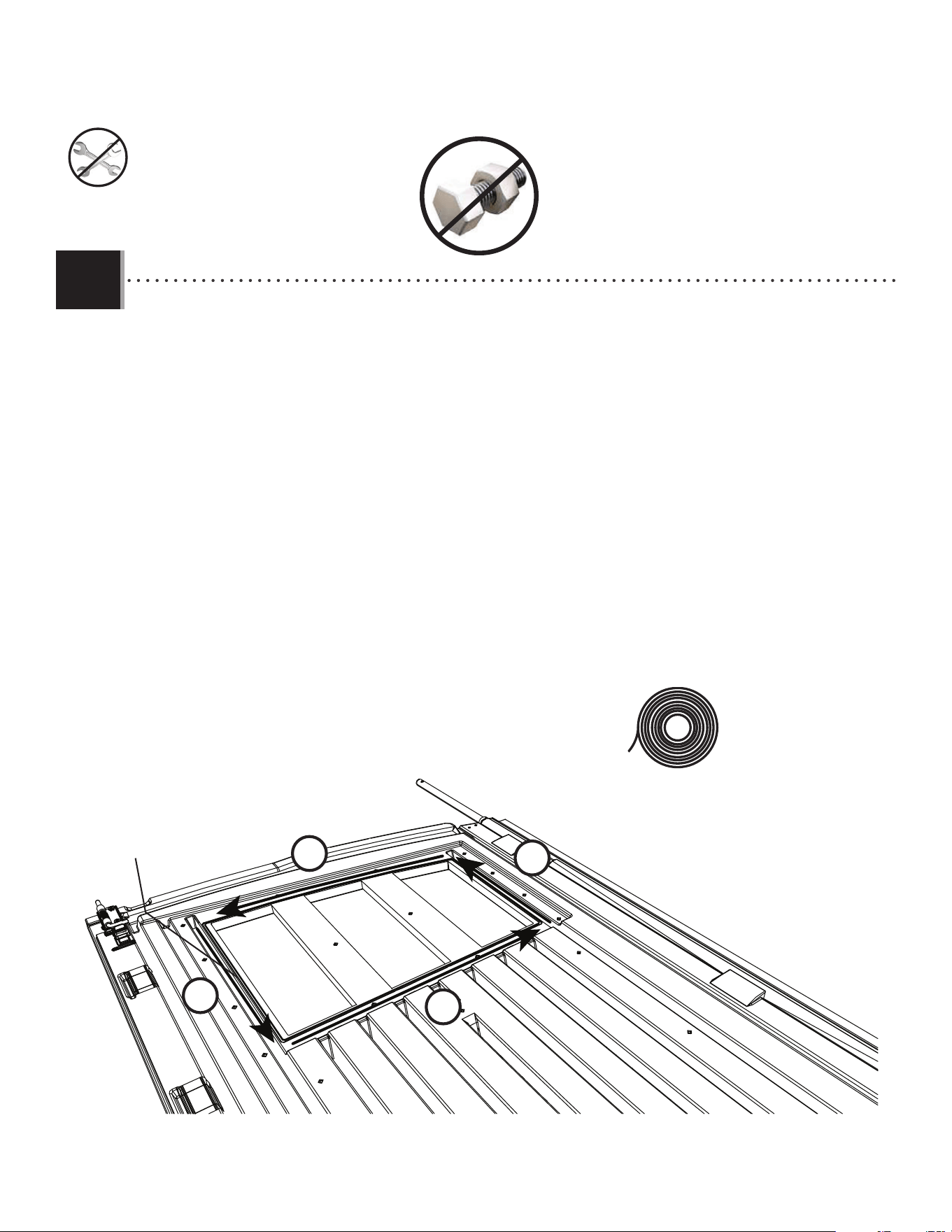
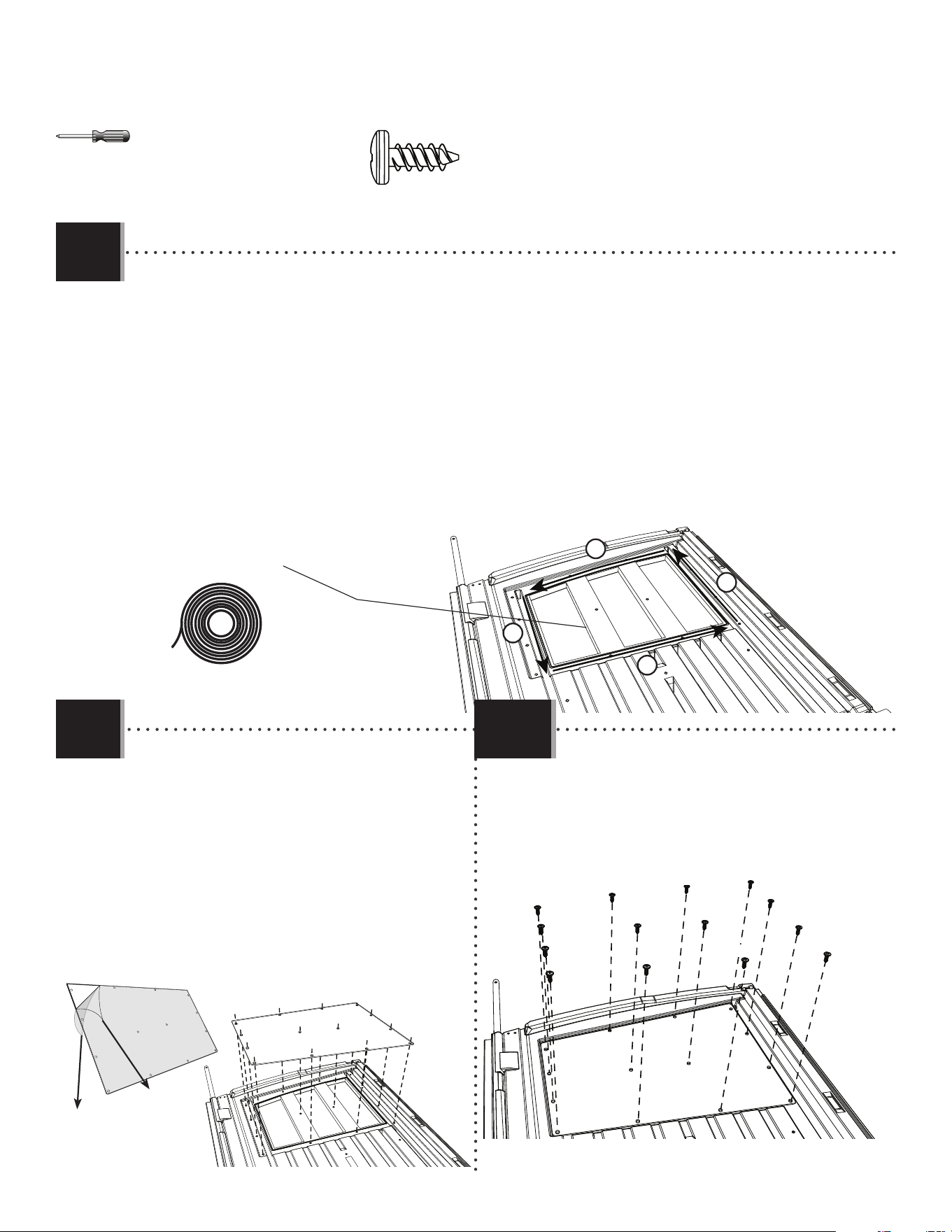
• There is a narrow groove (illustrated in black) running along the outside of the window on the back of each door.
Starting at the top, left corner of the groove in the left door, lay the butyl tape (EPH) into the groove. Do not worry about getting
the tape completely into the groove just yet—simply lay the tape over the groove. Do not press the tape into the groove. Do not stretch the tape. Work your
way downward (1) and, as you get to each corner, peel o the paper backing from the tape you just laid (peel o
backing at each corner). Go along the bottom (2) of the window. Curve your way upward (3) and then along the top
(4) of the window until you’re back where you started. Clip o the excess.
• Une rainure étroite (illustrée en noir) se trouve le long de l’extérieur de la fenêtre à l’arrière de chaque porte.
Partant du coin supérieur gauche de la rainure de la porte gauche, étendre de ruban de butyl (EPH) dans la rainure.
Ne pas s’inquiéter si le ruban n’est pas complètement dans la rainure en ce moment, ne faire que déposer le ruban sur la rainure. Ne pas étirer le ruban. Ne
pas pousser le ruban dans la rainure. Travailler vers le bas (1) et, en approchant chaque courbe, retirer le papier
protecteur du ruban qui à été étendé (retirer le papier protecteur a chaque courbe). Étendre le ruban le long du
bas (2) de la fenêtre. Courber vers le haut (3), puis le long du haut (4) de la fenêtre jusqu’à ce qu’il soit au point de
départ. Couper l’excédent.
• Hay una ranura angosta (ilustrada en negro) bordeando la ventana en la superfi cie posterior de cada puerta.
Comenzando desde arriba, en la esquina izquierda de la ranura en la puerta izquierda, aplicar de de cinta butílica
(EPH) en la ranura. Ne preocuparse por poner la cinta completamente en la ranura, mas solamente sobre la ranura. No presionar la cinta dentro de la ranura.
No estirar la línea. Seguir hacia abajo (1) y, al acercar cada ángulo, quitar el papel protector de la cinta que apenas
aplicó (quitar el papel protector a cada ángulo). Seguir a lo largo del borde inferior (2) de la ventana. Curvearla
hacia arriba (3) y, entonces, a lo largo del borde superior (4) de la ventana hasta estar al punto de partida. Cortar el
exceso.
Groove / Rainure / Ranura
EPH (x1)
1
2
3
4
2.7
18
TOOLS AND HARDWARE REQUIRED / OUTILS ET QUINCAILLERIE REQUIS / INSTRUMENTAL Y HERRAJE REQUERIDOS
X SECTION 2 (CONTINUED) / SECTION 2 (SUITE) / SECCIÓN 2 (CONTINUACIÓN)
ADZ (x14)
DHN
ADZ
ADZ
ADZ
ADZ
ADZ
ADZ
ADZ
ADZ
ADZ
ADZ
ADZ
ADZ
ADZ
ADZ
• Peel o the protective cover on both sides of the window pane. Align the holes in the pane with those in the door,
and gently set a window pane (DHN) down onto the door.
• Retirer la pellicule protectrice des deux côtés du carreau. Aligner les trous dans le carreau avec ceux de la porte,
et, avec douceur, mettre le carreau (DHN) sur la porte.
• Retirar el protector de plástico de las dos caras de una hoja. Alinear los agujeros en la hoja con los de la puerta, y
colocar ligeramente la hoja de ventana (DHN) en la puerta.
• Secure the pane to the door using fourteen (14) screws (ADZ).
• Fixer le carreau à la porte en utilisant quatorze (14) vis (ADZ).
• Fijar la hoja a la puerta usando catorce (14) tornillos (ADZ).
2.8
2.9
DHN
19
EOZ (x1)
FWZ
HARDWARE REQUIRED / QUINCAILLERIE REQUISE / HERRAJE REQUERIDO
Metal parts / Pièces en métal / Piezas de metal
Plastic parts / Pièces en plastique / Piezas de plástico
PARTS REQUIRED / PIÈCES REQUISES / PIEZAS REQUERIDAS
BDK (x1)
BBH (x1)
AEE (x3)
EPA (x1)
AAB (x2)
EPC (x2)
ACH (x2)
GHO (x1)*
BYZ (x2)
BBI (x1)
ADW (x1)
AEB (x2)
CXK (x2)
BYS (x1)
BYR (x1)
FVW(x1)
EDW (x1)
7/16 in/po
(≈11 mm)
3/8 in/po
(≈10 mm)
ADZ (x14)
DHL
EPH (x1)
DHN (x1)
RIGHT DOOR ASSEMBLY / ASSEMBLAGE DE LA PORTE DROITE / ENSAMBLAJE DE LA PUERTA DERECHA
3
CHK (x1)
TOOLS REQUIRED / OUTILS REQUIS / INSTRUMENTAL REQUERIDO
(Not included—unless otherwise indicated*) / (Non inclus — sauf indication contraire*) / (No incluido, salvo indicación contraria*)
Parts / Pièces / Piezas
Top end / Extrémité supérieure / Extremo superior
20
TOOLS AND HARDWARE REQUIRED / OUTILS ET QUINCAILLERIE REQUIS / INSTRUMENTAL Y HERRAJE REQUERIDOS
X SECTION 3 (CONTINUED) / SECTION 3 (SUITE) / SECCIÓN 3 (CONTINUACIÓN)
3.1
3.2
BBH (x1)
BDK
EDW
BBH
• Slide a square tube (EDW) into the square hole at the bottom of the right door (BDK) until about 6" (≈15 cm) of the tube
hang out of the hole.
• Faire glisser un tube carré (EDW) dans le trou carré au bord inférieur de la porte droite (BDK) jusqu’à ce que environ ≈15 cm
(6 po) étendent du trou.
• Deslizar un tubo cuadrado (EDW) en el orifi cio cuadrado a la parte inferior de la puerta derecha (BDK) hasta que unos ≈15 cm
(6 in) cuelguen del agujero.
• Insert the end cap (BBH) into the end of the square tube and continue inserting the tube until it is fl ush with the
bottom of the door. Align the two holes in the tube with the two holes in the door. If necessary, gently tap with a
rubber mallet.
• Insérer un capuchon (BBH) dans l’extrémité du tube carré et continuer à insérer le tube jusqu’à ce qu’il soit à ras
del borde inférieur de la porte. Aligner les deux trous dans le tube avec les deux trous dans la porte. Si besoin,
frapper soigneusement avec un maillet en caoutchouc.
• Insertar un tapón (BBH) en el extremo del tubo cuadrado y continuar a insertar el tubo hasta que esté al ras del
borde inferior de la puerta. Alinear los dos agujeros en el tube con ellos en la puerta. Si es necesario, golpear
cuidadosamente con un mazo de goma.
• Align these holes
• Aligner ces trous
• Alinear estos agujeros
http://go.lifetime.com/compactmodernshed-section3
LIFETIME
®
• In case of troubles with this section, scan the QR code below to view a video on its assembly.
• En cas d’avoir des problèmes avec cette section, scanner le code QR en dessous pour voir un vidéo de l’assemblage.
• En caso de tener problemas con esta sección, escanear el código QR debajo para ver un video del ensamblaje.
Top end / Extrémité supérieure / Extremo superior
21
TOOLS AND HARDWARE REQUIRED / OUTILS ET QUINCAILLERIE REQUIS / INSTRUMENTAL Y HERRAJE REQUERIDOS
X SECTION 3 (CONTINUED) / SECTION 3 (SUITE) / SECCIÓN 3 (CONTINUACIÓN)
3.3
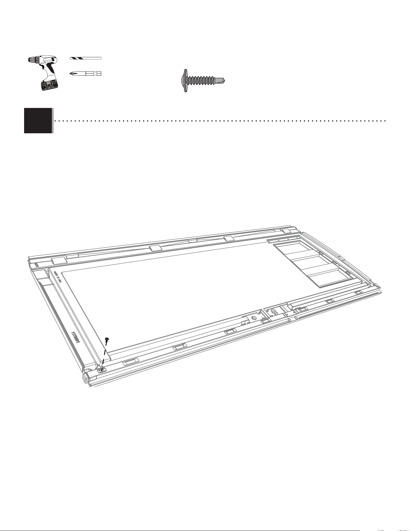
• Flip the door over. Using the 5/32" (≈4 mm) drill bit (GHO) included and an electric drill, drill through the divot near the bottom
edge of the door and into the square tube. Do not drill all the way through the door. Insert a screw (CHK) through the door and into the
square tube. This will secure the square tube inside the door.
• Retournez la porte. En utilisant le foret de 5/32" (≈4 mm) (GHO) inclus et une perceuse électrique, percer la petite impression vers
le fond de la porte et dans le tube carré. Ne pas percer de face en face. Insérer une vis (CHK) à travers la porte et dans le tube carré.
Ainsi, le tube carré à l’intérieur de la porte sera fi xé.
• Voltee la puerta. Usando la broca de 5/32" (≈4 mm) (GHO) incluida y un taladro eléctrico, taladrar por la marca cerca el fondo de la
puerta y dentro el tubo cuadrado. No taladrar por completo la puerta. Insertar un tornillo (CHK) por la puerta y dentro del tubo cuadrado.
Esto asegurará el tubo cuadrado dentro de la puerta.
GHO
ADC (x1)*
CHK (x1)
CHK (x1)
22
TOOLS AND HARDWARE REQUIRED / OUTILS ET QUINCAILLERIE REQUIS / INSTRUMENTAL Y HERRAJE REQUERIDOS
X SECTION 3 (CONTINUED) / SECTION 3 (SUITE) / SECCIÓN 3 (CONTINUACIÓN)
• Attach the latch as shown. Ensure the tube inside the door is fl ush with the bottom of the door, then tighten securely.
• Attacher le loquet tel qu’a ché. Veiller à ce que le tube à l’intérieur de la porte est égal avec le bas de la porte,
puis bien serrer.
• Sujetar el cerrojo como se muestra. Asegurarse que el tubo dentro de la puerta está alineado con la parte inferior de
la puerta, y apriete fi rmemente.
BYS
BYR
• Attach the two handle pieces (BYR & BYS) together as shown.
• Attacher les deux pièces de la poignée (BYR et BYS) ensemble tel qu’a ché.
• Conectar las dos piezas de la maninja (BYR y BYS) como se muestra.
7/16 in/po
(≈11 mm)
3/8 in/po
(≈10 mm)
EOZ
EPA
AAB (x2)
AAB
AAB
ACH (x2)
ACH
ACH
AEB (x2)
AEE (x2)
CXK (x2)
CXK
CXK
EPC (x2)
EPC
EPC
AEB
AEB
AEE
AEE
3.4
3.5
23
TOOLS AND HARDWARE REQUIRED / OUTILS ET QUINCAILLERIE REQUIS / INSTRUMENTAL Y HERRAJE REQUERIDOS
X SECTION 3 (CONTINUED) / SECTION 3 (SUITE) / SECCIÓN 3 (CONTINUACIÓN)
• Attach the handle as shown. Tighten securely.
• Attacher la poignée comme a ché. Bien serrer.
• Sujetar bien la manija como se muestra. Apretar bien.
ADW (x1)
ADW
BYZ (x2)
BYZ
BYZ
AEE (x1)
AEE
BBI
3.6
24
TOOLS AND HARDWARE REQUIRED / OUTILS ET QUINCAILLERIE REQUIS / INSTRUMENTAL Y HERRAJE REQUERIDOS
X SECTION 3 (CONTINUED) / SECTION 3 (SUITE) / SECCIÓN 3 (CONTINUACIÓN)
3.7
• Slide a hinge tube (FVW) into the hole at the bottom of the door until a few inches remain out of the bottom. If necessary, use a
rubber mallet to gently tap the tube into place. This tube has a hole at both ends.
• Faire glisser un tube de charnière (FVW) dans le trou au fond de la porte jusqu’à ce qu’il ne reste que quelques centimètres
hors du bas. Si besoin, employer un maillet en caoutchouc pour taper le tube en place. Ce tube a une trous à chaque extrémité.
• Deslizar un tubo de bisagra (FVW) en el orifi cio al fondo de la puerta hasta que unos centímetros queden fuera de la parte
inferior. Si es necesario, usar un mazo de goma para golpear el tube en su lugar. Este tubo tiene un agujero a cada extremo.
FVW
• Holes
• Trous
• Agujeros
25
TOOLS AND HARDWARE REQUIRED / OUTILS ET QUINCAILLERIE REQUIS / INSTRUMENTAL Y HERRAJE REQUERIDOS
X SECTION 3 (CONTINUED) / SECTION 3 (SUITE) / SECCIÓN 3 (CONTINUACIÓN)
• There is a narrow groove (illustrated in black) running along the outside of the window on the back of each door. Starting
at the top, right corner of the groove in the right door, lay the butyl tape (EPH) into the groove. Do not worry about getting the tape completely
into the groove just yet—simply lay the tape over the groove. Do not press the tape into the groove. Work your way downward (1), and curve to go along the
bottom (2) of the window. Curve your way upward (3) and then along the top (4) of the window until you’re back where you
started. Clip o the excess.
• Une rainure étroite (illustrée en noir) se trouve le long de l’extérieur de la fenêtre à l’arrière de chaque porte. Partant du
coin supérieur droit de la rainure de la porte droite, étendre le ruban butyl (EPH) dans la rainure. Ne pas s’inquiéter si le ruban n’est pas
complètement dans la rainure en ce moment; ne faire que déposer le ruban sur la rainure. Ne pas pousser le ruban dans la rainure. Travailler vers le bas (1), et courber
pour atteindre le bas (2) de la fenêtre. Courber vers le haut (3), puis le long du haut (4) de la fenêtre jusqu’à revenir au point
de départ. Couper l’excédent.
• Hay una ranura angosta (ilustrada en negro) bordeando la ventana en la superfi cie posterior de cada puerta.
Comenzando desde arriba, en la esquina derecha de la ranura en la puerta derecha, aplicar la cinta de butílica (EPH) en la
ranura. Ne preocuparse por poner la cinta, mas poner la cinta sobre la ranura solamente. No presionar la cinta dentro de la ranura. Siga hacia abajo (1), y curvearla
a lo largo del borde inferior (2) de la ventana. Curvearla hacia arriba (3) y, entonces, a lo largo del borde superior (4) de la
ventana hasta estar al punto de partida. Cortar el exceso.
Groove / Rainure / Ranura
EPH (x1)
3.8
3.9
DHN
• Peel o the protective cover on both sides of the
window pane. Align the holes in the pane with
those in the door, and gently set a window pane (DHN)
down onto the door.
• Retirer la pellicule protectrice des deux côtés
du carreau. Aligner les trous dans le carreau
avec ceux de la porte, et, avec douceur, mettre
le carreau (DHN) sur la porte.
• Retirar el protector de plástico de las dos caras
de una hoja. Alinear los agujeros en la hoja con
los de la puerta, y colocar ligeramente la hoja de
ventana (DHN) en la puerta.
• Secure the pane to the door using fourteen (14)
screws (ADZ).
• Fixer le carreau à la porte en utilisant quatorze
(14) vis (ADZ).
• Fijar la hoja a la puerta usando catorce (14)
tornillos (ADZ).
ADZ
ADZ
ADZ
ADZ
ADZ
ADZ
ADZ
ADZ
ADZ (x14)
1
2
3
4
DHN
3.10
ADZ
ADZ
ADZ
ADZ
ADZ
ADZ
26
AHO (x2)
FXC
Plastic parts / Pièces en plastique / Piezas de plástico
PARTS REQUIRED / PIÈCES REQUISES / PIEZAS REQUERIDAS
HARDWARE REQUIRED / QUINCAILLERIE REQUISE / HERRAJE REQUERIDO
CUW (x2)
CWU (x6)
These are not anchoring screws. Their purpose is to fasten together the fl oor panels.
Ces vis ne sont pas de vis d’ancrage. Leur but est pour attacher les panneaux de plancher.
Estos no son tornillos de anclaje. Son propósito es sólo para unir los paneles de piso.
FLOOR ASSEMBLY / ASSEMBLAGE DU PLANCHER / ENSAMBLAJE DEL PISO
4
TOOLS REQUIRED / OUTILS REQUIS / INSTRUMENTAL REQUERIDO
(Not included—unless otherwise indicated*) / (Non inclus — sauf indication contraire*) / (No incluido, salvo indicación contraria*)
27
TOOLS AND HARDWARE REQUIRED / OUTILS ET QUINCAILLERIE REQUIS / INSTRUMENTAL Y HERRAJE REQUERIDOS
X SECTION 4 (CONTINUED) / SECTION 4 (SUITE) / SECCIÓN 4 (CONTINUACIÓN)
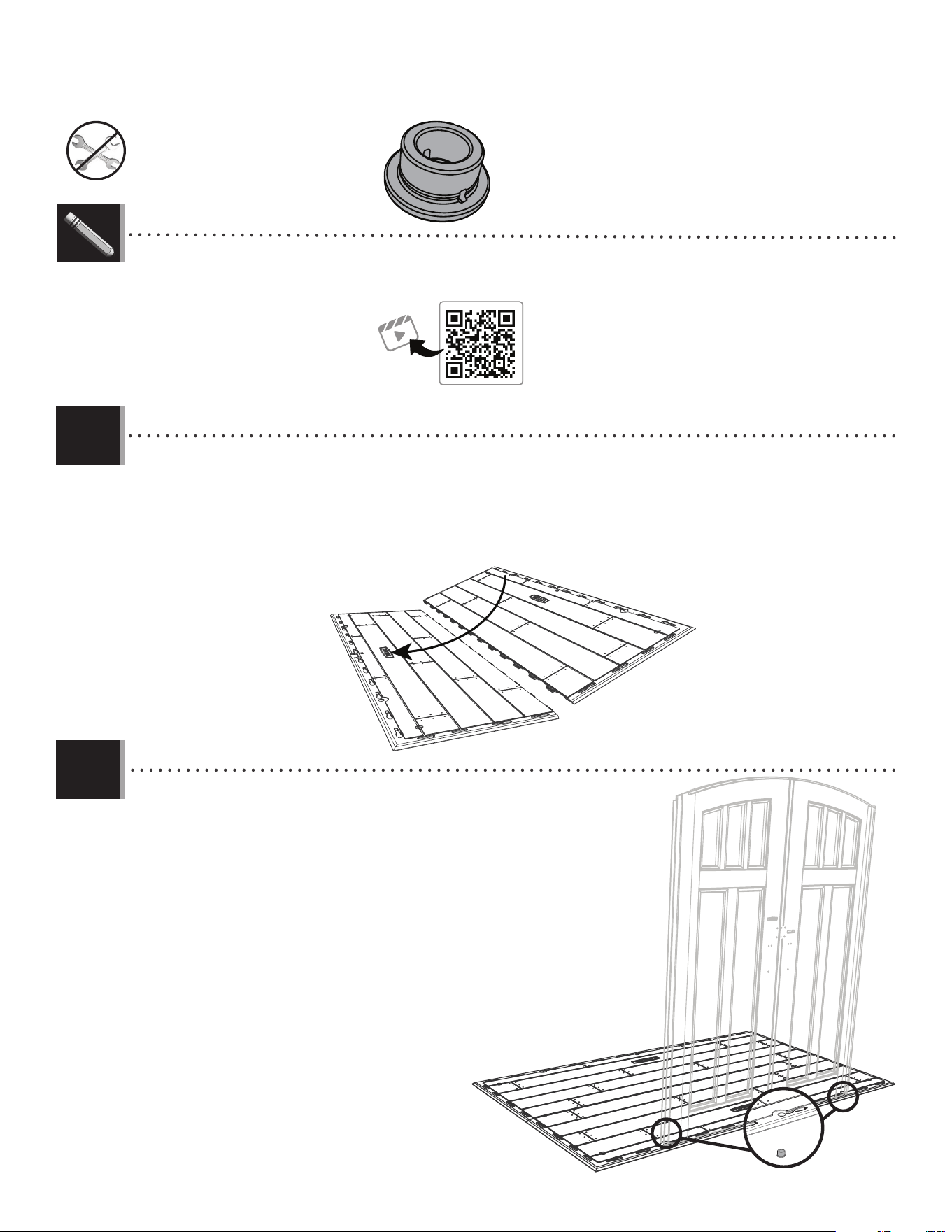
4.1
4.2
CUW
CUW
• Slide the tabs along the edge of an outer fl oor panel (CUW) underneath the other outer fl oor panel (CUW). The tabs interlock.
Lay panel down fl at.
• Faire glisser les languettes le long du bord d’un panneau de plancher extérieur (CUW) au-dessus de l’autre panneau de plancher
extérieur (CUW). Les languettes s’enclenchent les uns les autres. L’étendre par terre.
• Deslizar las lenguetas a lo largo del borde de un panel de piso exterior (CUW) debajo el otro panel de piso exterior (CUW). Las
lengüetas se entrelazan las unas con las otras. Aplanar el panel.
• Insert the door bushings (AHO) through the holes in the fl oor. The slit in the bushing should face the
front of the shed.
• Insérer les bagues des portes (AHO) à travers les trous dans le plancher. La fente dans la bague
doit donner sur le bord avant de l’abri.
• Insertar los casquillos de las puertas (AHO) a través de los agujeros en el piso. La rendija en el
casquillo debe dar hacia el borde delantero de la caseta.
AHO
AHO (x2)
http://go.lifetime.com/compactmodernshed-section4
LIFETIME
®
• In case of troubles with this section, scan the QR code below to view a video on its assembly.
• En cas d’avoir des problèmes avec cette section, scanner le code QR en dessous pour voir un vidéo de l’assemblage.
• En caso de tener problemas con esta sección, escanear el código QR debajo para ver un video del ensamblaje.
28
TOOLS AND HARDWARE REQUIRED / OUTILS ET QUINCAILLERIE REQUIS / INSTRUMENTAL Y HERRAJE REQUERIDOS
X SECTION 4 (CONTINUED) / SECTION 4 (SUITE) / SECCIÓN 4 (CONTINUACIÓN)
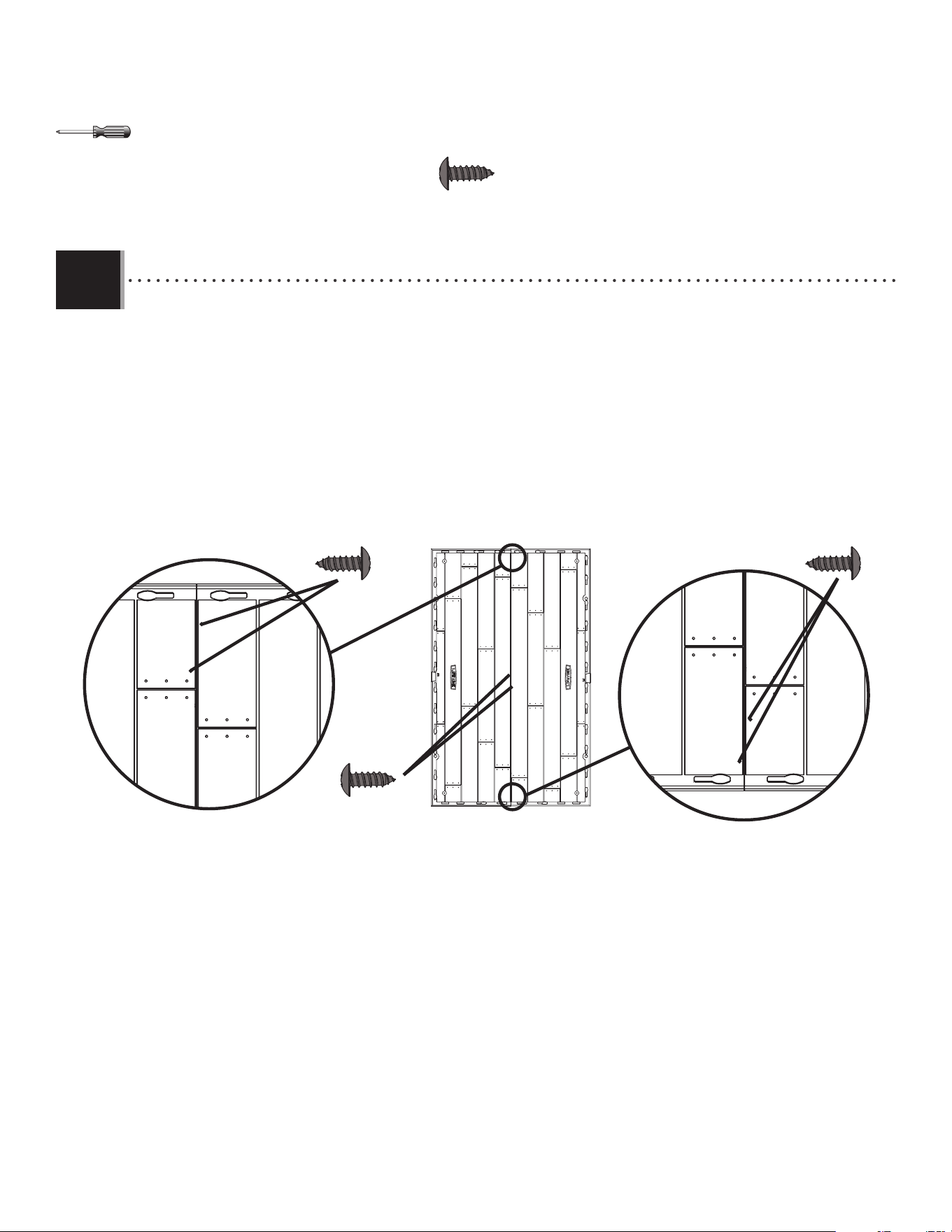
4.3
CWU (x6)
• Insert the screws (CWU) through the divots in the fl oor panels and into the tabs of the adjacent fl oor panels. (The
divots are near the seams of the fl oor panels.) These screws do not anchor the fl oor; they only hold the panels together.
• Insérer les vis (CWU) à travers les marques dans les panneaux de plancher et dans les languettes du panneaux de
plancher contigu. (Les marques se trouvent près des jonctions des panneaux de plancher.) Ces vis n’ancrent pas le
plancher; ils ne servent que pour attacher les panneaux les uns avec les autres.
• Insertar los tornillos (CWU) a través de las marcas en los paneles de piso y dentro de las lengüetas des los paneles de
piso adyacentes. (Se encuentran las marcas cerca de las junturas de los paneles de piso.) Estos tornillos no anclan el piso;
sirven sólo para sujetar los paneles los unos con los otros.
CWU (x2)
CWU (x2)
CWU (x2)
29
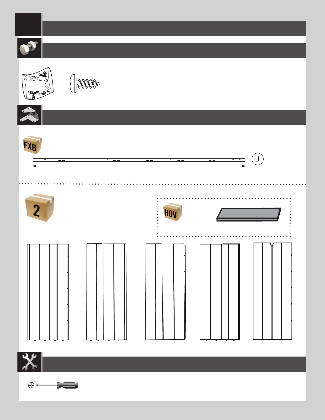
ADZ (x60)*
AHD (x4)
AIW (x1)*
AGW (x1)
AGY (x1)
AGN (x1)
AGL (x1)
FXE
Plastic parts / Pièces en plastique / Piezas de plástico
PARTS REQUIRED / PIÈCES REQUISES / PIEZAS REQUERIDAS
HARDWARE REQUIRED / QUINCAILLERIE REQUISE / HERRAJE REQUERIDO
* Not all hardware will be used in the section.
* La quincaillerie n’est pas utilisée au complet dans la section.
* No se utilizará todo el herraje en la sección.
67 3/4 in/po (≈1,72 m)
AFM (x6)
Metal parts / Pièces en métal / Piezas de metal
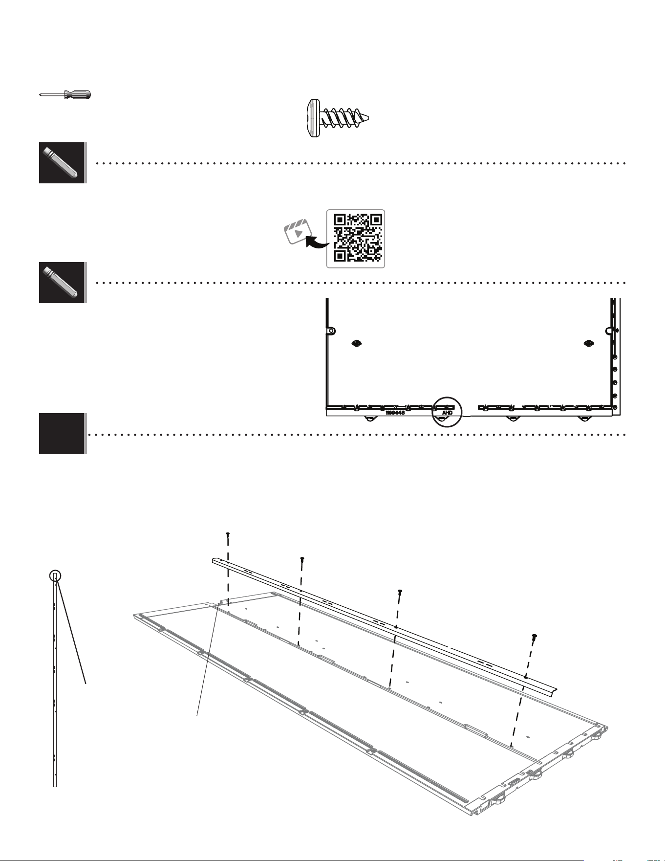
WALL ASSEMBLY / ASSEMBLAGE DES MURS / ENSAMBLAJE DE LOS MUROS
5
TOOLS REQUIRED / OUTILS REQUIS / INSTRUMENTAL REQUERIDO
(Not included—unless otherwise indicated*) / (Non inclus — sauf indication contraire*) / (No incluido, salvo indicación contraria*)
67 3.4 in/po (≈172 cm)
30
TOOLS AND PARTS REQUIRED / OUTILS ET QUINCAILLERIE REQUIS / INSTRUMENTAL Y HERRAJE REQUERIDOS
X SECTION 5 (CONTINUED) / SECTION 5 (SUITE) / SECCIÓN 5 (CONTINUACIÓN)
5.1
ADZ (x16)
• No screw in top hole.
• Aucune vis dans le
trou supérieur.
• Ningún tornillo en el
agujero superior.
• Top end
• Extrémité
supérieure
• Extremo
superior
Bottom / Bord inférieur / Borde inferior
• Notch
• Encoche
• Muesca
AFM
AHD
ADZ
ADZ
ADZ
ADZ
• Secure a wall support channel (AFM) just to the left of the notch on the four (4) wall panels (AHD) using four (4) screws (ADZ) for
each.
• Fixer un canal de support mural (AFM) juste à gauche de l’encoche sur les quatre (4) panneaux muraux (AHD) en utilisant quatre
(4) vis (ADZ) pour chacun.
• Sujetar un canal de soporte mural (AFM) justo a la izquierda de la muesca en los cuatro (11) paneles murales (AHD) usando
cuatro (4) tornillos (ADZ) para cada uno.
• At the bottom of the back of each wall panel is a three-letter ID
(AHD, AGN, AGW or AGY). This will help you identify the correct
panel during assembly.
• Il y a un identifi eur de trois lettres (AHD, AGN, AGW ou AGY) au
fond de la face arrière de chaque panneau mural. Cela aide à
identifi er le panneau correct pendant l’assemblage.
• Hay una identifi cación de tres letras (AHD, AGN, AGW ou AGY)
en la parte inferior de la cara trasera de cada panel mural. Ésta
ayuda a identifi car el panel correcto durante el ensamblaje.
http://go.lifetime.com/compactmodernshed-section5
• In case of troubles with this section, scan the QR code below to view a video on its assembly.
• En cas d’avoir des problèmes avec cette section, scanner le code QR en dessous pour voir un vidéo de l’assemblage.
• En caso de tener problemas con esta sección, escanear el código QR debajo para ver un video del ensamblaje.
LIFETIME
®
LIFETIME
®
31
TOOLS AND PARTS REQUIRED / OUTILS ET QUINCAILLERIE REQUIS / INSTRUMENTAL Y HERRAJE REQUERIDOS
X SECTION 5 (CONTINUED) / SECTION 5 (SUITE) / SECCIÓN 5 (CONTINUACIÓN)
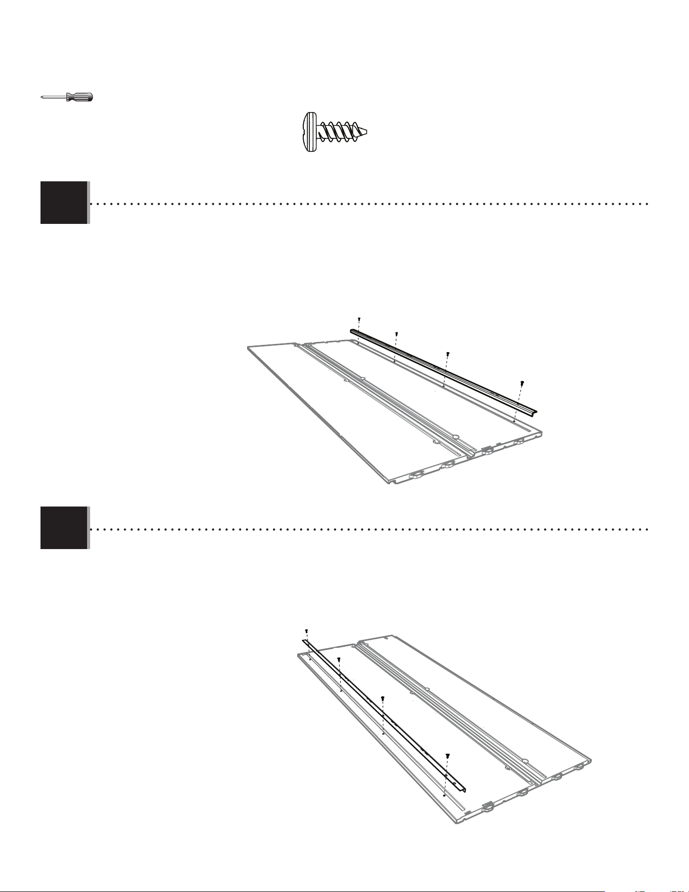
5.2
5.3
• Secure a wall support channel (AFM) to the corner wall panel (AGN) using four (4) screws (ADZ). The end with two holes goes at the bottom.
• Fixer le canal de support mural (AFM) au panneau mural en coin (AGN) en utilisant quatre (4) vis (ADZ). L’extrémité avec deux trous va sur le
dessous.
• Sujetar un canal de soporte mural (AFM) al panel mural de esquina (AGN) usando cuatro (4) tornillos (ADZ). El extremo con dos agujeros va en la
parte inferior.
AGN
ADZ
ADZ
ADZ
ADZ
AFM
ADZ (x8)
• Secure a wall support channel (AFM) to the corner wall panel (AGY) using four (4) screws (ADZ). The end with two holes goes at the top.
• Fixer un canal de support mural (AFM) au panneau mural en coin (AGY) en utilisant quatre (4) vis (ADZ). L’embout avec deux trous va sur le
dessus.
• Sujetar un canal de soporte mural (AFM) al panel mural de esquina (AGY) usando cuatro (4) tornillos (ADZ). El extremo con dos agujeros va a la
parte superior.
AGY
AFM
ADZ
ADZ
ADZ
ADZ
32
TOOLS AND PARTS REQUIRED / OUTILS ET QUINCAILLERIE REQUIS / INSTRUMENTAL Y HERRAJE REQUERIDOS
X SECTION 5 (CONTINUED) / SECTION 5 (SUITE) / SECCIÓN 5 (CONTINUACIÓN)
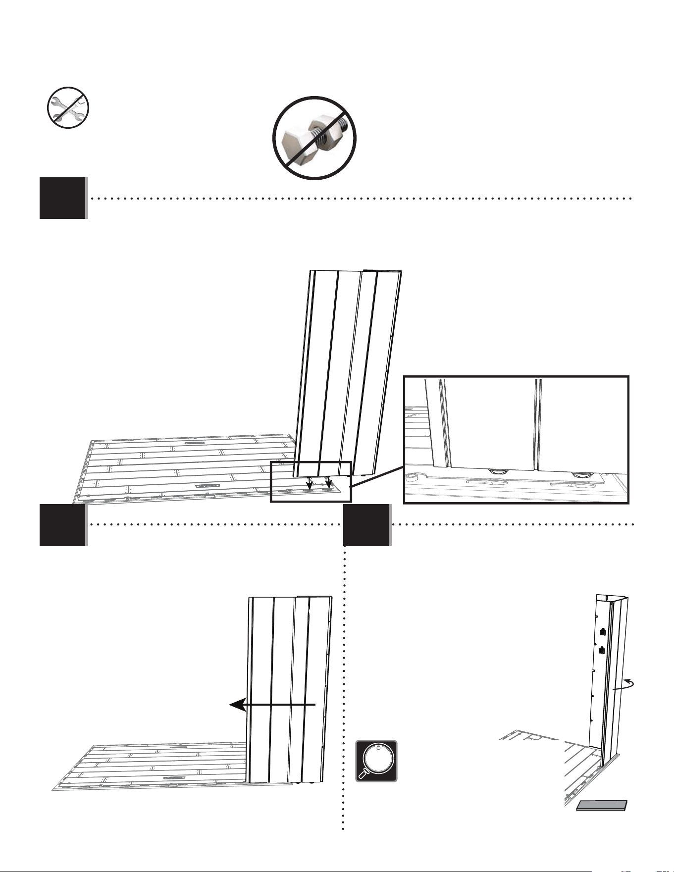
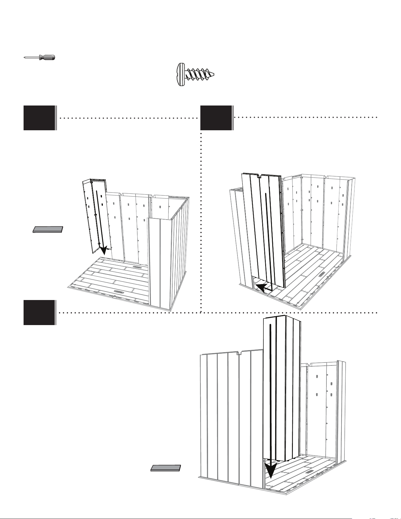
• Insert the two left-most tabs at the bottom of the corner panel (AGY) into the two right-most slots along the edge of the
fl oor.
• Insérer les deux languettes gauches au bord inférieur du panneau angulaire (AGY) dans les deux rainures droites le long
du bord du plancher.
• Insertar las lengüetas al borde inferior del panel angular (AGY) en las ranuras a lo largo del borde del piso.
AGY
• Bend the corner panel and position the tabs
over the two slots in the fl oor panel. Pull down on
the panel to insert the two remaining tabs into
the slots.
• Plier le panneau angulaire et position les
languettes sur les deux fentes dans le
panneau de plancher. Tirer vers le bas
le panneau pour insérer les languettes
dans les fentes.
• Doblar el panel angular y posicione las
lengüetas encima de las dos ranuras
en el panel de piso. Tirar para abajo el
panel para insertar las lengüetas en las
ranuras.
5.4
5.6
5.5
AIW (x1)
• Slide the panel to the left.
• Faire glisser le panneau à gauche.
• Deslizar el panel a la izquierda.
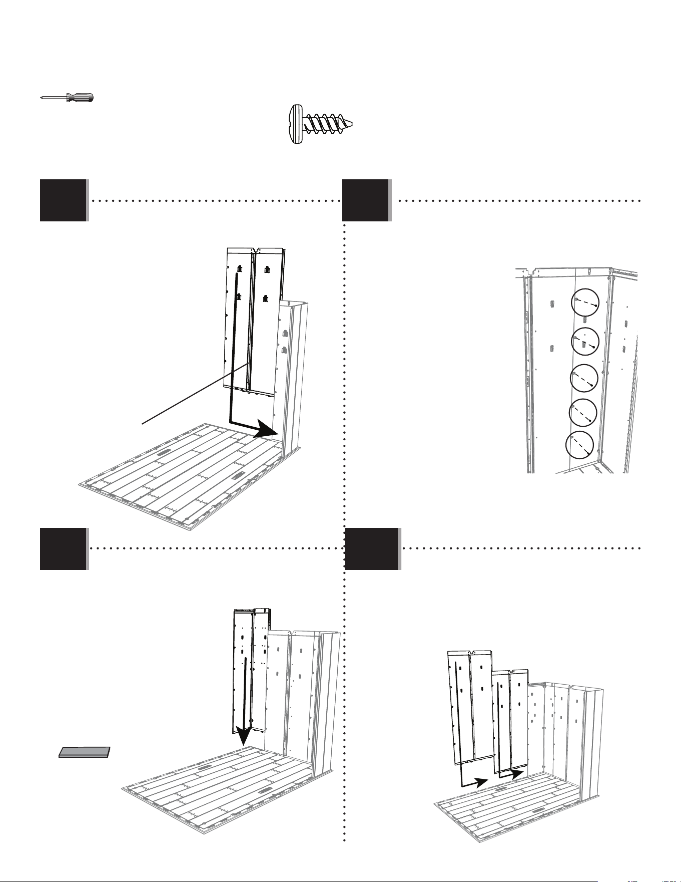
• To help with insertion, slide the plastic block
(AIW) under the fl oor directly under the tab being
inserted.
• Pour aider avec la insertion, faire glisser le bloc en
plastique (AIW) sous le plancher directement sous
la languette à insérer.
• Para ayudar con la inserción, deslizar el bloque de
plastico (AIW) debajo el piso directamente debajo
de la lengüeta que se va a insertar.
AGY
33
TOOLS AND PARTS REQUIRED / OUTILS ET QUINCAILLERIE REQUIS / INSTRUMENTAL Y HERRAJE REQUERIDOS
X SECTION 5 (CONTINUED) / SECTION 5 (SUITE) / SECCIÓN 5 (CONTINUACIÓN)
• Slide two wall panels (AHD) into place at the rear of
the fl oor. Secure with screws (ADZ).
• Faire glisser deux panneaux muraux (AHD) en place au
bord arrière du plancher. Les attacher à l’aide
des vis (ADZ).
• Deslizar dos paneles murales (AHD) en su lugar al
borde trasero del piso. Sujetarlos usando tornillos
(ADZ).
ADZ (x20)
AHD
AHD
5.7 5.8
5.10
5.9
AIW (x1)
• Secure the two panel
together using fi ve (5)
screws (ADZ). Do not overtighten.
The attachment points have a thin
membrane that the screws will
puncture.
• Attacher les deux
panneaux l’un à l’autre
à l’aide des cinq (5)
vis (ADZ). Ne pas serrer
excessivement les vis. Les vis
perforeront les membranes fi nes
situées aux points d’attache.
• Sujetar los dos paneles
el uno al otro usando
cinco (5) tornillos (ADZ). No
apretar demasiado los tornillos.
Los tornillos perforán las
membranas delgadas situadas en
los puntos de conexión.
• Insert this corner panel (AGW) like the fi rst corner wall
panel. Secure with screws (ADZ).
• Insérer ce panneau angulaire (AGW) comme le primier
panneau angulaire.
Bien l’attacher à
l’aide des vis (ADZ).
• Insertar este panel
angular (AGW) como
el primer panel
angular. Sujetarlo
con tornillos (ADZ).
AGW
• Slide a wall panel (AHD) into place.
• Faire glisser un panneau mural (AHD) en place.
• Deslizar un panel mural (AHD) en su lugar.
AHD
AFM
34
TOOLS AND PARTS REQUIRED / OUTILS ET QUINCAILLERIE REQUIS / INSTRUMENTAL Y HERRAJE REQUERIDOS
X SECTION 5 (CONTINUED) / SECTION 5 (SUITE) / SECCIÓN 5 (CONTINUACIÓN)
ADZ (x15)
AGN
AIW (x1)
5.11
5.13
• Slide a wall panel (AHD) into place along the left side of the
fl oor. Secure with screws (ADZ).
• Faire glisser un panneau mural (AHD) en place au bord
gauche du plancher. L’attacher à l’aide des vis (ADZ).
• Deslizar un panel mural (AHD) en su lugar al borde izquierdo
del piso. Sujetarlo con tornillos (ADZ).
• Insert the last corner panel (AGN) in the same
way as the previous one. Secure with screws
(ADZ).
• Insérer le dernier panneau angulaire (AGN) de la
même manière que le panneau angulaire
précédent. Bien l’attacher à l’aide des vis
(ADZ).
• Insertar el último panel angular (AGN) de la
misma manera que el panel angular
anterior. Sujetarlo con tornillos (ADZ).
AHD
AGL
• Insert this corner panel (AGL) like the fi rst corner wall
panel. Secure with screws (ADZ).
• Insérer ce panneau angulaire (AGL) comme le primier
panneau angulaire. Bien l’attacher à l’aide des
vis (ADZ).
• Insertar este panel angular (AGL) como el primer
panel angular. Sujetarlo con tornillos (ADZ).
5.12
AIW (x1)
35
GIE (x1)
GIF (x1)
PARTS REQUIRED / PIÈCES REQUISES / PIEZAS REQUERIDAS
HARDWARE REQUIRED / QUINCAILLERIE REQUISE / HERRAJE REQUERIDO
EPH (x2)
EPI (x1)
FWB (x2)
FWC (x2)
GKF (x2)
ADZ (x84)
AEE (x8)
ADX (x8)
TRANSOM & GABLE ASSEMBLY / ASSEMBLAGE DE L’IMPOSTE ET DES PIGNONS / ENSAMBLAJE DEL MONTANTE Y DE LAS
FACHADAS
6
AHP (x2)
FXF
CONTENTS OF SMALL PARTS KIT / CONTENU DE LA TROUSSE DE PETITES PIÈCES / CONTENIDO DEL KIT DE PIEZAS PEQUEÑAS
36
Plastic parts / Pièces en plastique / Piezas de plástico
PARTS REQUIRED / PIÈCES REQUISES / PIEZAS REQUERIDAS
GDV (x1)
GDU (x1)
GDT (x1)
GDW (x1)
TRANSOM & GABLE ASSEMBLY / ASSEMBLAGE DE L’IMPOSTE ET DES PIGNONS / ENSAMBLAJE DEL MONTANTE Y DE LAS
FACHADAS
6
TOOLS REQUIRED / OUTILS REQUIS / INSTRUMENTAL REQUERIDO
(Not included—unless otherwise indicated*) / (Non inclus — sauf indication contraire*) / (No incluido, salvo indicación contraria*)
37
TOOLS AND HARDWARE REQUIRED / OUTILS ET QUINCAILLERIE REQUIS / INSTRUMENTAL Y HERRAJE REQUERIDOS
X SECTION 6 (CONTINUED) / SECTION 6 (SUITE) / SECCIÓN 6 (CONTINUACIÓN)
6.1
TRANSOM ASSEMBLY / ASSEMBLAGE DE L’IMPOSTE / ENSAMBLAJE DEL TRAVESAÑO
Groove / Rainure / Ranura
EPH (x2)
1
3
2
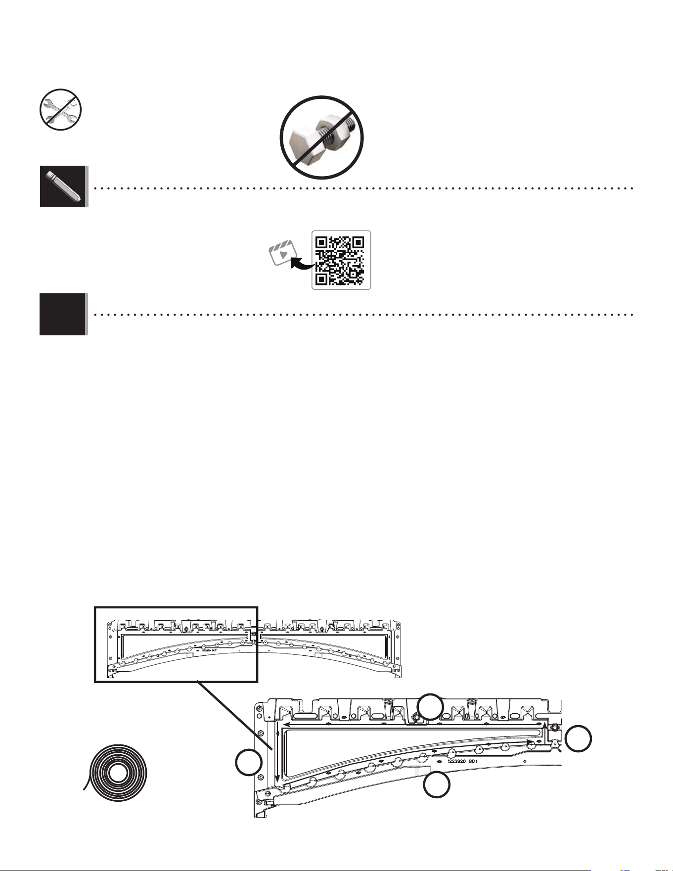
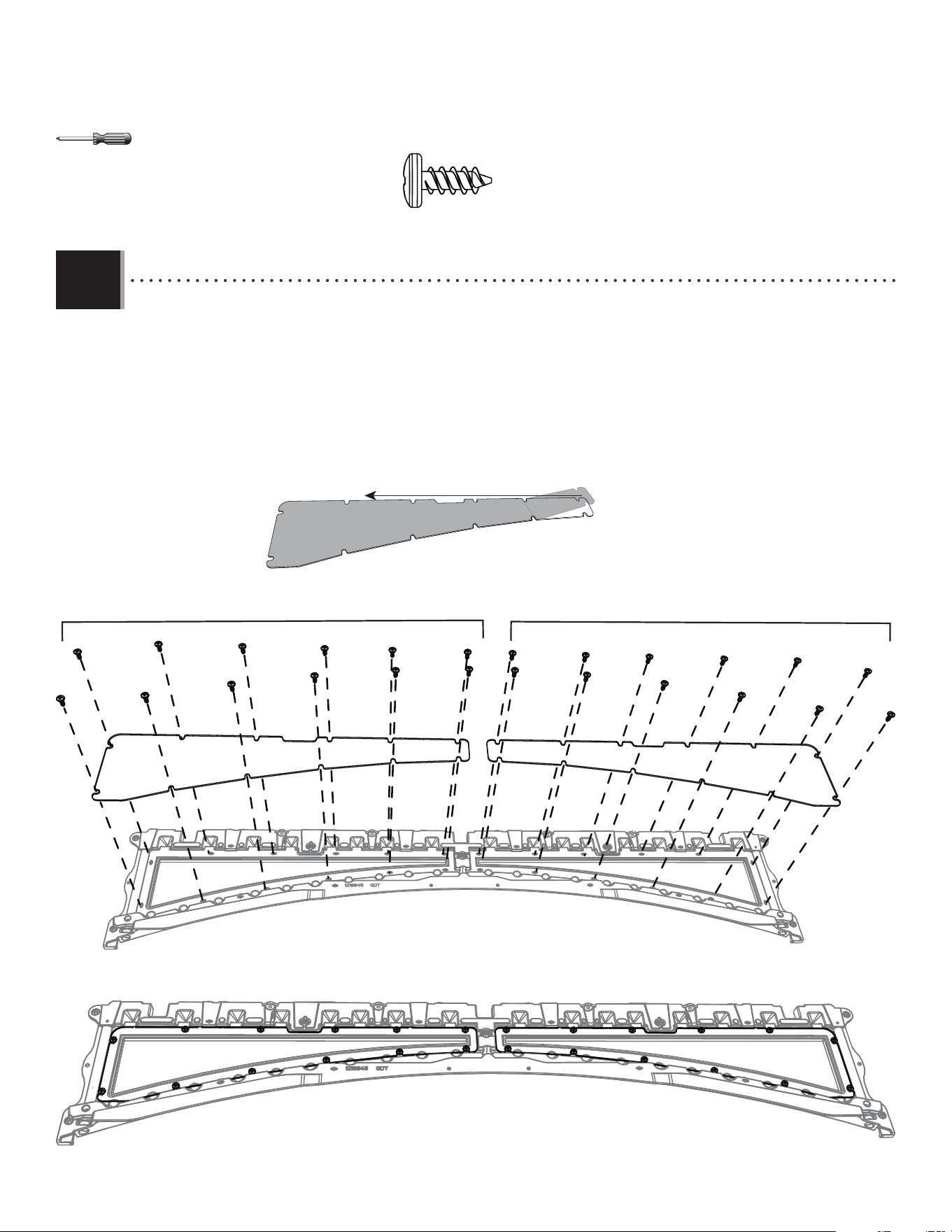
• There is a narrow groove (illustrated in black) running along the outside of the windows on the transom (GDT). Starting
at the top, left corner of the groove in the left transom window, lay the Butyl Tape (EPH) into the groove. Do not worry about
getting the tape completely into the groove just yet—simply lay the tape over the groove. Do not press the tape into the groove. Do not stretch the tape. Work
your way downward (1) and, as you get to each corner, peel o the paper backing from the tape you just laid (peel
o backing at each corner). Go along the bottom (2) of the window. Curve your way upward (3) and then along the
top (4) of the window until you’re back where you started. Clip o the excess. Repeat this step for the right window.
• Il y a une rainure mince (illustrée en noir) sous l’extérieur des fenêtres sur l’imposte (GDT). En commençant dans le
coin supérieur gauche de la rainure de l’imposte de la fenêtre de gauche, insérer du ruban de butyle (EPH) dans la rainure.
Ne pas essayer encore d’insérer le ruban complètement dans la rainure, positionner simplement le ruban par-dessus la rainure. Ne pas pousser sur le ruban
pour l’insérer dans la rainure. Ne pas étirer le ruban. Travailler vers le bas (1) et, en arrivant à chaque coin, décoller le papier de
protection du ruban a juste collé (décoller le papier à chaque coin). Avancer le long de la partie inférieure (2) de
la fenêtre. Tourner vers le haut (3) et ensuite le long de la partie supérieure (4) de la fenêtre pour enfi n revenir au
point de départ. Découper l’excès. Répéter cette étape pour la fenêtre de droite.
• Hay una ranura estrecha (ilustrada en negro) que corre a lo largo del exterior de las ventanas en el travesaño (GDT).
Comenzando en la esquina superior izquierda de la ranura en la ventana del travesaño izquierdo, colocar la cinta
de butilo (EPH) en la ranura. No se preocupar por introducir la cinta completamente en la ranura todavía, simplemente colocar la cinta sobre la ranura. No
presionar la cinta en la ranura. No estirar la cinta. Trabajar hacia abajo (1) y, al llegar a cada esquina, retirar el papel de respaldo
de la cinta recientemente colocada (retirar el papel de respaldo de cada esquina). Pasar a lo largo de la parte
inferior (2) de la ventana. Trabajar siguiendo una curva hacia arriba (3) y luego a lo largo de la parte superior (4) de
la ventana hasta regresar al punto de partida. Recortar el exceso. Repetir este paso para la ventana derecha.
GDT
4
http://go.lifetime.com/compactmodernshed-section6
LIFETIME
®
• In case of troubles with this section, scan the QR code below to view a video on its assembly.
• En cas d’avoir des problèmes avec cette section, scanner le code QR en dessous pour voir un vidéo de l’assemblage.
• En caso de tener problemas con esta sección, escanear el código QR debajo para ver un video del ensamblaje.
38
TOOLS AND HARDWARE REQUIRED / OUTILS ET QUINCAILLERIE REQUIS / INSTRUMENTAL Y HERRAJE REQUERIDOS
X SECTION 6 (CONTINUED) / SECTION 6 (SUITE) / SECCIÓN 6 (CONTINUACIÓN)
6.2
• Peel the protective fi lm from both sides of the two (2) transom window panes (FWC). Secure the window panes to the transom
(GDT) using twelve (12) screws (ADZ) each. Do not overtighten the hardware.
• Enlever la fi lm protecteur des deux côtés des deux (2) carreaux de l’imposte (FWC). Bien attacher les carreaux à l’imposte (GDT) à
l’aide de douze (12) vis (ADZ) chacun. Ne pas trop serrer les quincaillerie.
• Pelar la película protectora de ambos lados de los dos (2) hojas del montante (FWC). Fijar bien las hojas al montante (GDT)
usando doce (12) tornillos (ADZ) cada una. No apretar demasiado los herraje.
ADZ (x24)
GDT
FWC
FWC
ADZ (x12)
ADZ (x12)
FWC
39
TOOLS AND HARDWARE REQUIRED / OUTILS ET QUINCAILLERIE REQUIS / INSTRUMENTAL Y HERRAJE REQUERIDOS
X SECTION 6 (CONTINUED) / SECTION 6 (SUITE) / SECCIÓN 6 (CONTINUACIÓN)
6.3
GABLE ASSEMBLY / ASSEMBLAGE DES PIGNONS / ENSAMBLAJE DE LAS FACHADAS
EPI (x1)
4
1
3
2
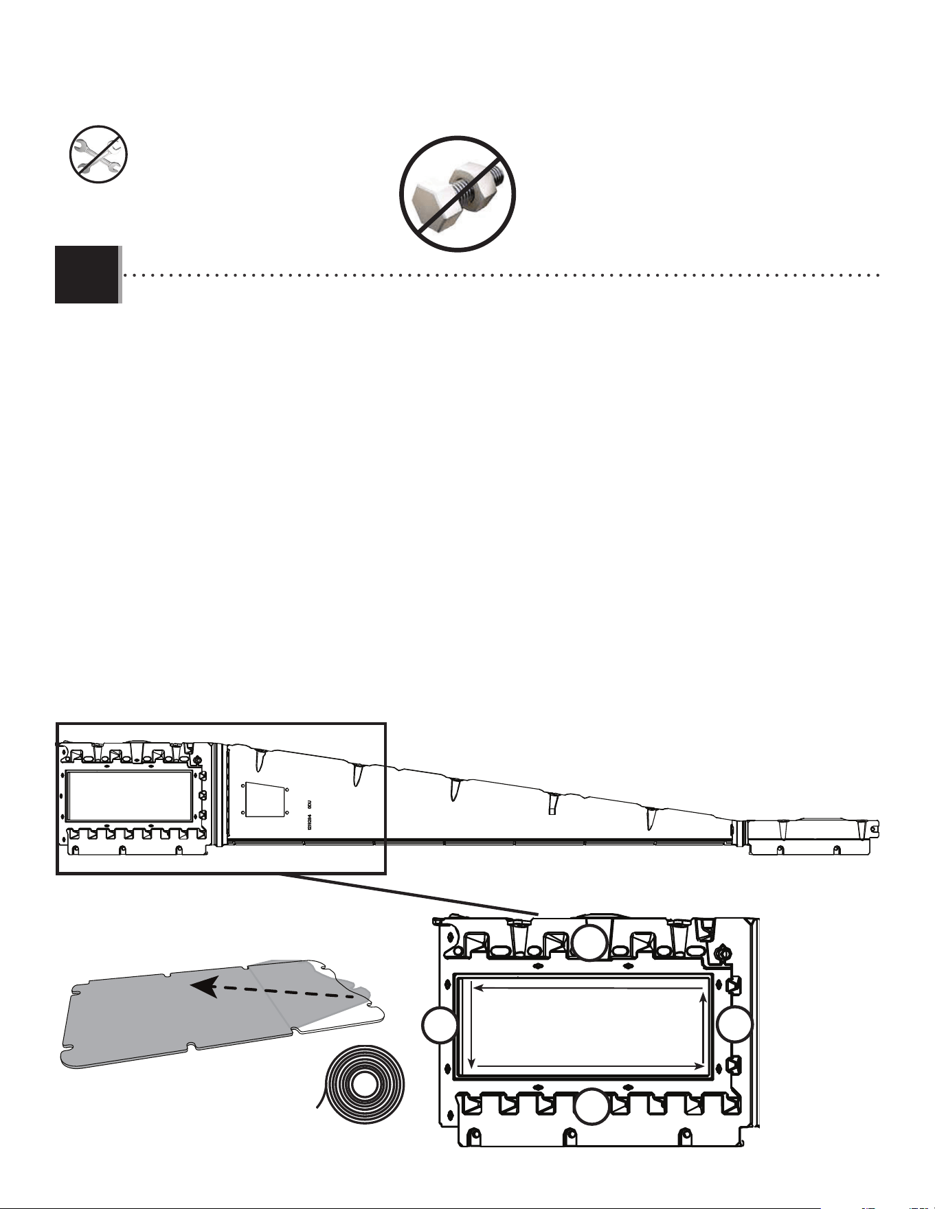
• There is a narrow groove (illustrated in black) running along the outside of the windows on the gable. Starting at
the top, left corner of the groove in the left gable window (GDU), lay the butyl tape (EPI) into the groove. Do not worry about getting
the tape completely into the groove just yet—simply lay the tape over the groove. Do not press the tape into the groove. Do not stretch the tape. Work your
way downward (1) and, as you get to each corner, peel o the paper backing from the tape you just laid (peel o
backing at each corner). Go along the bottom (2) of the window. Curve your way upward (3) and then along the top
(4) of the window until you’re back where you started. Clip o the excess and use it to repeat this step for the right gable window. Peel o
the protective cover on both sides of the window pane.
• Il y a une rainure mince (illustrée en noir) sous l’extérieur des fenêtres dans le pignon. En commençant dans le
coin supérieur gauche de la rainure de l’imposte de la fenêtre de gauche du pignon (GDU), insérer du ruban de butyle (EPI) dans la
rainure. Ne pas essayer encore d’insérer le ruban complètement dans la rainure, positionner simplement le ruban par-dessus la rainure. Ne pas pousser sur le
ruban pour l’insérer dans la rainure. Ne pas étirer le ruban. Travailler vers le bas (1) et, en arrivant à chaque coin, décoller le papier
de protection du ruban a juste collé (décoller le papier de protection à chaque coin). Avancer le long de la partie
inférieure (2) de la fenêtre. Tourner vers le haut (3) et ensuite le long de la partie supérieure (4) de la fenêtre pour
enfi n revenir au point de départ. Découper l’excès de ruban et l’utiliser pour répéter cette étape pour la fenêtre de droite du pignon. Retirer la
pellicule protectrice des deux côtés du carreau.
• Hay una ranura estrecha (ilustrada en negro) que corre a lo largo del exterior de las ventanas en el alero.
Comenzando en la esquina superior izquierda de la ranura en la ventana del alero izquierdo (GDU), coloque la cinta de butilo
(EPI) en la ranura. No se preocupe por introducir la cinta completamente en la ranura todavía, simplemente coloque la cinta sobre la ranura. No presione
la cinta en la ranura. No estire la cinta. Trabajar hacia abajo (1) y, al llegar a cada esquina, retirar el papel de respaldo de la
cinta recientemente colocada (retirar el papel de respaldo de cada esquina). Pasar a lo largo de la parte inferior
(2) de la ventana. Trabajar siguiendo una curva hacia arriba (3) y luego a lo largo de la parte superior (4) de la
ventana hasta regresar al punto de partida. Recortar el exceso y utilícelo para repetir este paso para la ventana de alero derecha. Retirar el
protector de plástico de las dos caras de una hoja.
GDU
FWB
40
TOOLS AND HARDWARE REQUIRED / OUTILS ET QUINCAILLERIE REQUIS / INSTRUMENTAL Y HERRAJE REQUERIDOS
X SECTION 6 (CONTINUED) / SECTION 6 (SUITE) / SECCIÓN 6 (CONTINUACIÓN)
ADZ (x8)
ADX (x4)
AEE (x4)
6.4
6.5
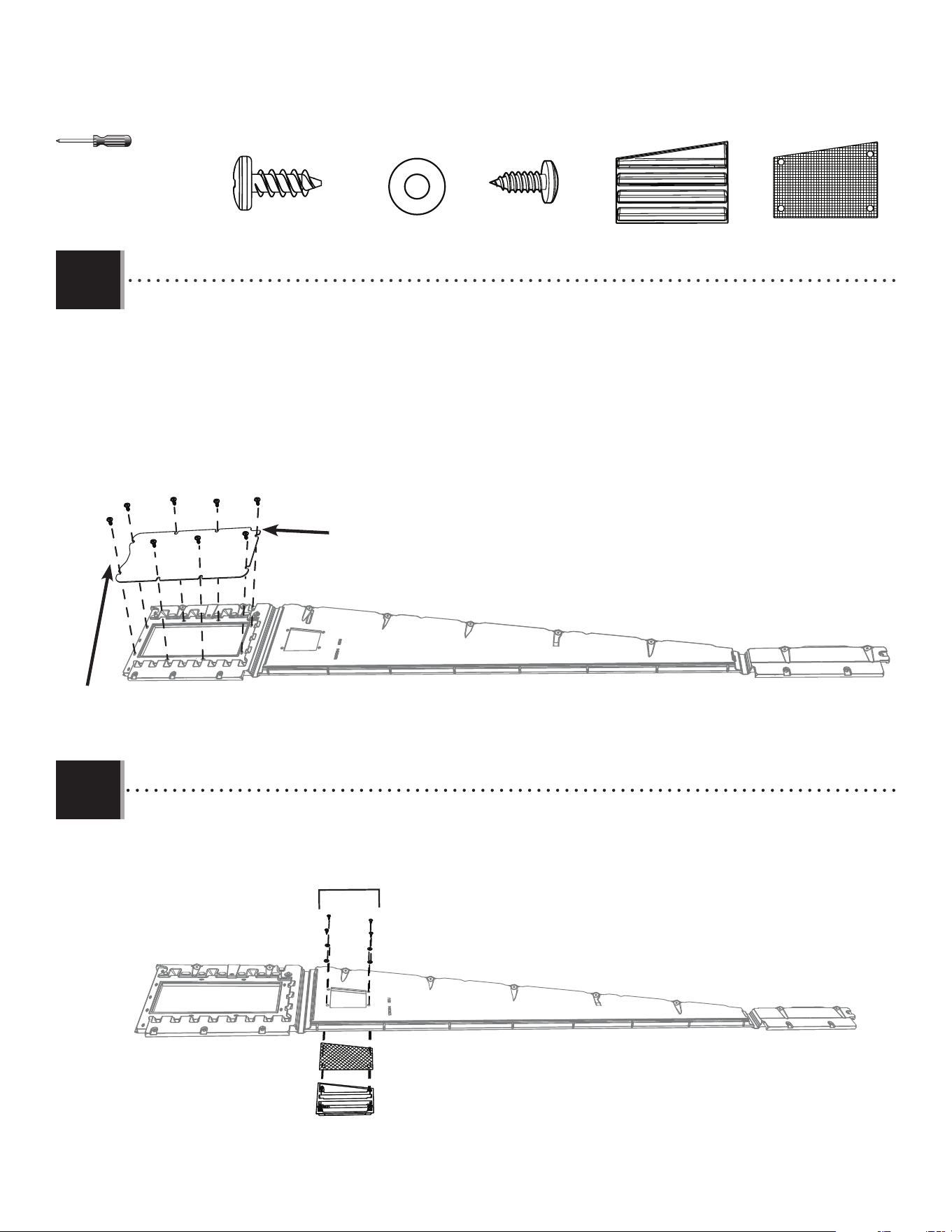
• Secure a vent (GIE) and screen (GKF) to the left gable (GDU) using four (4) screws (ADX) and washers (AEE).
• Bien attacher un évent (GIE) et une moustiquaire (GKF) au pignon gauche (GDU) à l’aide de quatre (4) vis (ADX) et rondelles (AEE).
• Fijar bien una rejilla de ventilación (GIE) y un mosquitero (GKF) a la fachada izquierdo (GDU) usando cuatro (4) tornillos (ADX) y rondanas (AEE).
GIE
GKF
GDU
ADX (x4)/AEE (x4)
GIE (x1)
GKF (x1)
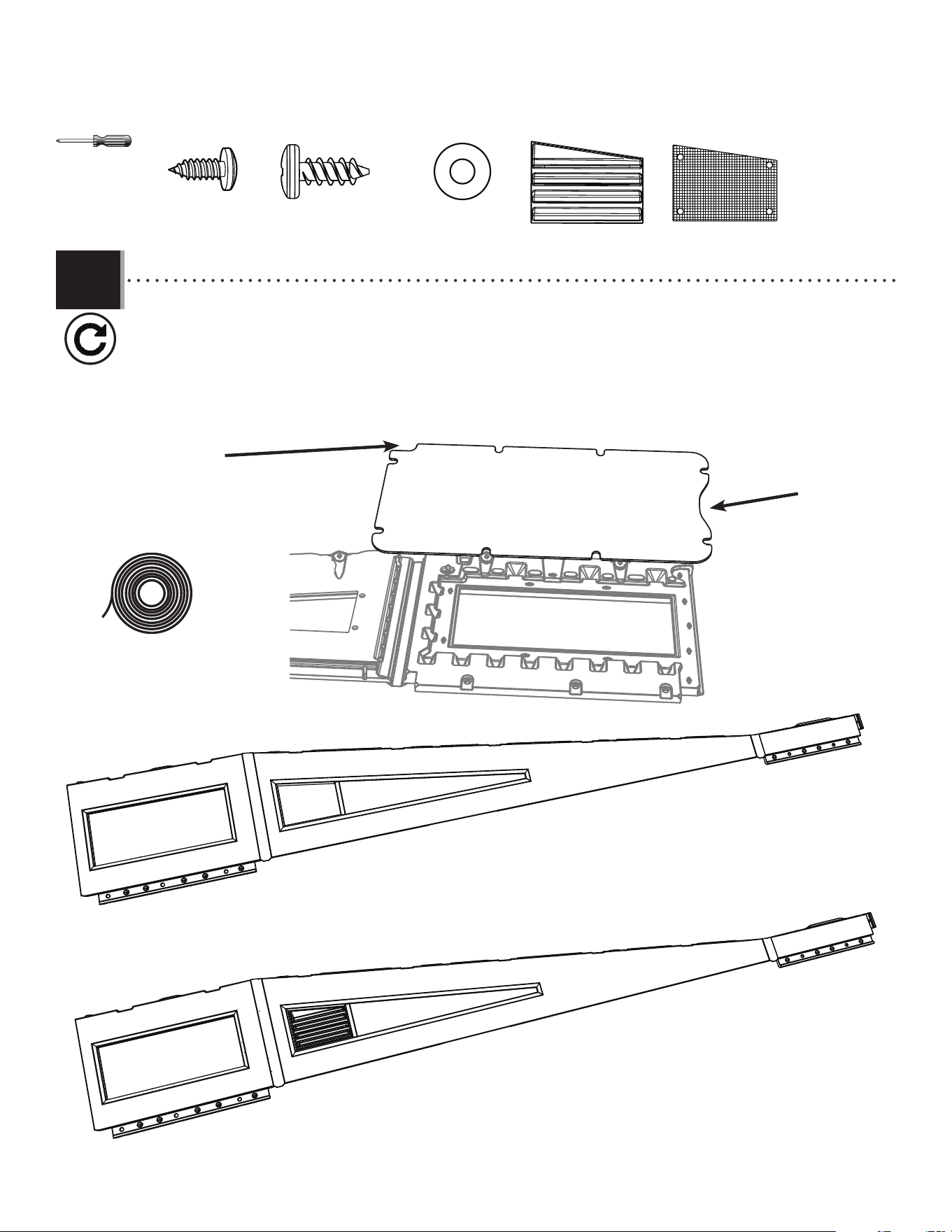
• Secure the window panes to the left gable (GDU) using eight (8) screws (ADZ) each. Do not overtighten the hardware. The curved side of
the window should be oriented toward the end of the panel. The indented corner must be oriented to the right-upper corner of the window.
• Bien attacher les carreaux au pignon guache (GDU) à l’aide de huit (8) vis (ADZ) chacun. Ne pas trop serrer la quincaillerie. Le côté courbe
de la fenêtre doit être orienté vers l’extrémité du panneau. Le coin découpé doit être dirigé vers le coin supérieur droit de la fenêtre.
• Fijar bien las hojas a la fachada izquierdo (GDU) usando ocho (8) tornillos (ADZ) cada una. No apretar demasiado el herraje. El lado curvo de
la ventana debe orientarse hacia el extremo del panel. La esquina con muesca debe estar orientada hacia la esquina superior derecha de la ventana.
ADZ (x8)
FWB
GDU
Curved side / Côté courbé /Lado curvo
Indented corner / Coin découpé / Esquina con muesca
41
TOOLS AND HARDWARE REQUIRED / OUTILS ET QUINCAILLERIE REQUIS / INSTRUMENTAL Y HERRAJE REQUERIDOS
X SECTION 6 (CONTINUED) / SECTION 6 (SUITE) / SECCIÓN 6 (CONTINUACIÓN)
GDV
6.6
• Repeat steps 6.3–6.5 for the right gable (GDV). The indented corner of the window pane must be oriented to the left-upper corner of the window.
• Répéter les étapes 6.3–6.5 pour le pignon droit (GDV). Le coin découpé de la vitre doit être dirigé vers le coin supérieur gauche de la fenêtre.
• Repetir los pasos 6.3–6.5 para la fachada derecho (GDV). La esquina con muesca del cristal de la ventana debe estar orientada hacia la esquina superior izquierda
de la ventana.
ADZ (x8)
ADX (x4)
AEE (x4)
GIF (x1)
GKF (x1)
EPI
Indented corner
Coin découpé
Esquina con muesca
Curved side
Côté courbé
Lado curvo
42
TOOLS AND HARDWARE REQUIRED / OUTILS ET QUINCAILLERIE REQUIS / INSTRUMENTAL Y HERRAJE REQUERIDOS
X SECTION 6 (CONTINUED) / SECTION 6 (SUITE) / SECCIÓN 6 (CONTINUACIÓN)
6.7
6.8
GDW
ADZ (x8)
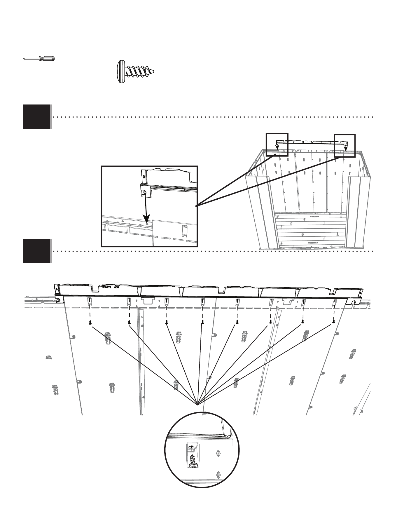
• Set the rear wall extension (GDW) on the rear wall panels. Slide the tabs toward
the inside of the walls.
• Mettre l’extension du mur arrière (GDW) sur les panneaux muraux arrières. Faire
glisser les ailettes vers l’intérieur des murs.
• Colocar la extensión del muro trasero (GDW) encima de los paneles murales
traseros. Deslizar las pestañas hacia el interior de las paredes.
• Attach the rear wall extension to the back wall with the hardware indicated.
• Fixer la rallonge de mur arrière au mur arrière avec la quincaillerie indiquée.
• Fijar la extensión de la pared trasera a la pared trasera con el herraje indicado.
X 8
ADZ
GDW
43
TOOLS AND HARDWARE REQUIRED / OUTILS ET QUINCAILLERIE REQUIS / INSTRUMENTAL Y HERRAJE REQUERIDOS
X SECTION 6 (CONTINUED) / SECTION 6 (SUITE) / SECCIÓN 6 (CONTINUACIÓN)
6.9
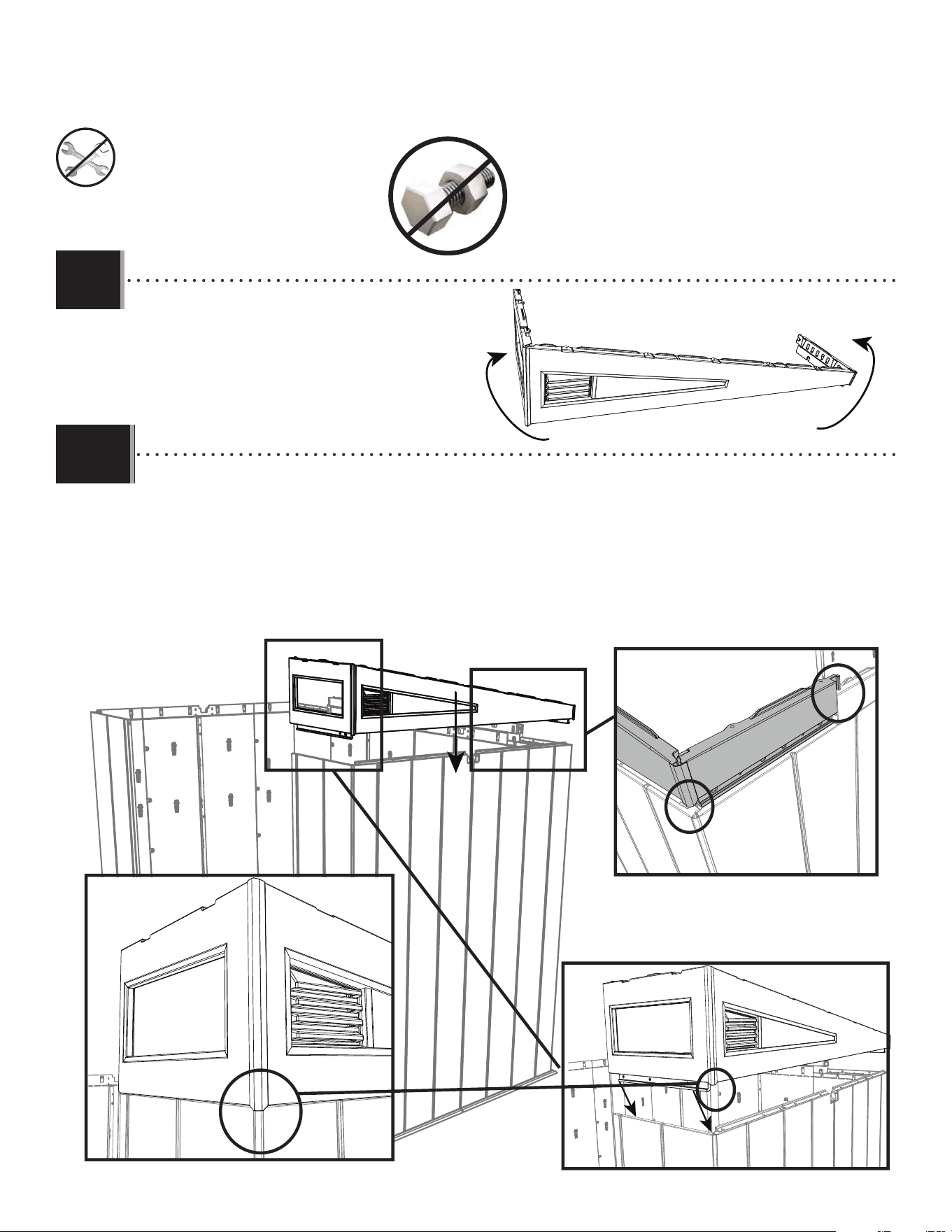
• Place the right gable assembly from steps 6.9 against the right wall and align the holes. The front and rear end of the gable
slides down over the front and rear walls.
• Placer l’assemblage du pignon de droite de l’étape6.9 contre le mur de droite et aligner les trous. Les extrémités avant
et arrière du pignon glissent par-dessus les murs avant et arrière.
• Colocar el conjunto del alero derecho de los pasos 6.9 contra la pared derecha y alinear los orifi cios. El extremo
delantero y trasero del alero se desliza hacia abajo sobre las paredes delantera y trasera.
• Fold the right gable assembly as shown below.
• Plier l’assemblage du pignon droit comme
indiqué ci-dessous.
• Doblar el conjunto del alero derecho como se
muestra a continuación.
6.10
44
TOOLS AND HARDWARE REQUIRED / OUTILS ET QUINCAILLERIE REQUIS / INSTRUMENTAL Y HERRAJE REQUERIDOS
X SECTION 6 (CONTINUED) / SECTION 6 (SUITE) / SECCIÓN 6 (CONTINUACIÓN)
6.11
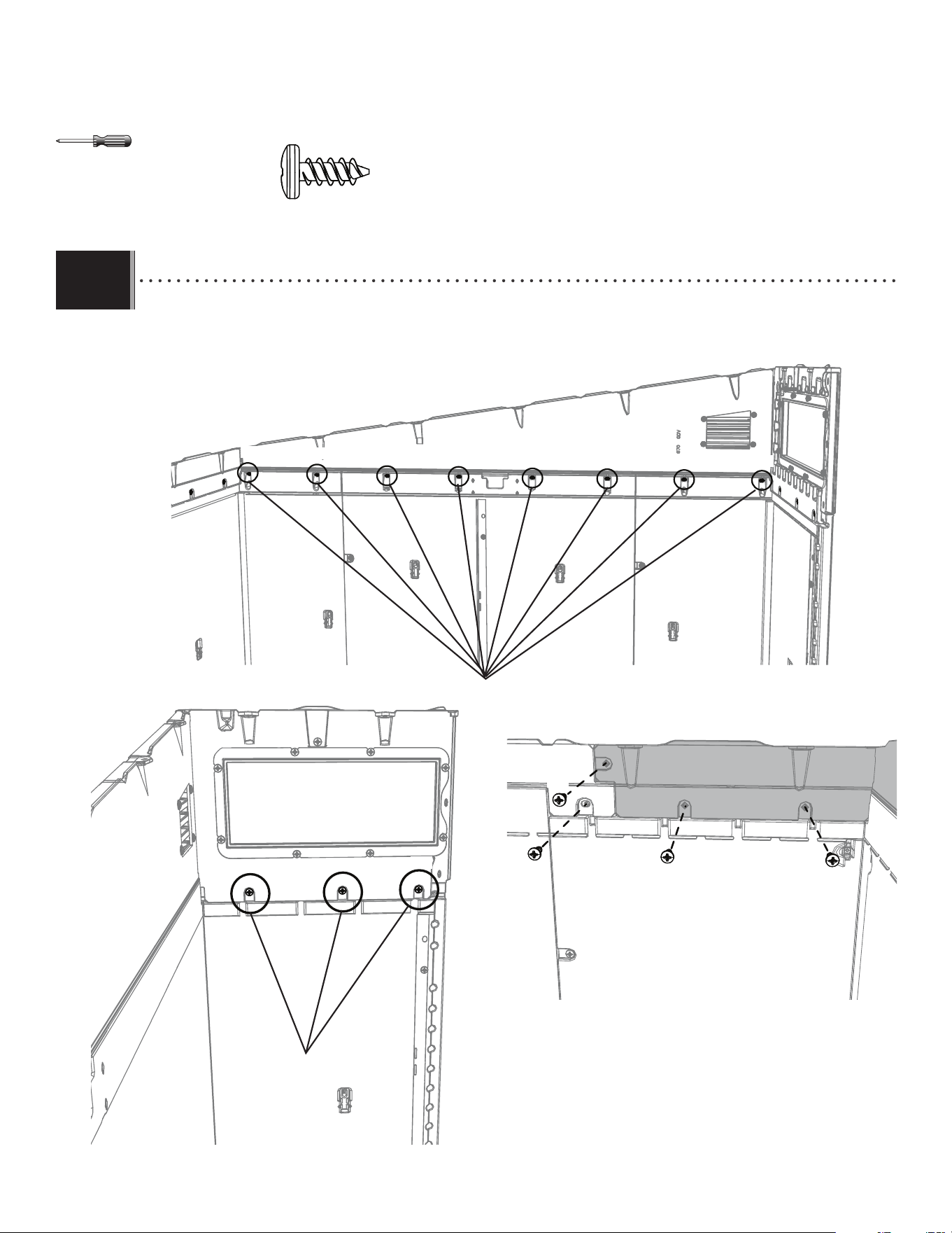
• Secure the gable to the right wall using fi fteen (15) screws (ADZ). Do not overtighten
• Bien attacher le pignon au mur droit à l’aide de quinze (15) viz (ADZ). Ne pas serrer excessivement.
• Fijar bien la fachada al muro derecho usando quince (15) tornillos (ADZ). No apretar demasiado.
X 8
ADZ (x15)
X 3
Side of gable / Côté du pignon / Lado del alero
Front of gable / Devant du pignon / Frente del alero
Rear of gable / Arrière du pignon / Parte trasera del alero
ADZ
ADZ
ADZ
ADZ ADZ
ADZ
ADZ
ADZ
ADZ
ADZ
ADZ
ADZ
ADZ
ADZ
ADZ
45
TOOLS AND HARDWARE REQUIRED / OUTILS ET QUINCAILLERIE REQUIS / INSTRUMENTAL Y HERRAJE REQUERIDOS
X SECTION 6 (CONTINUED) / SECTION 6 (SUITE) / SECCIÓN 6 (CONTINUACIÓN)
6.12
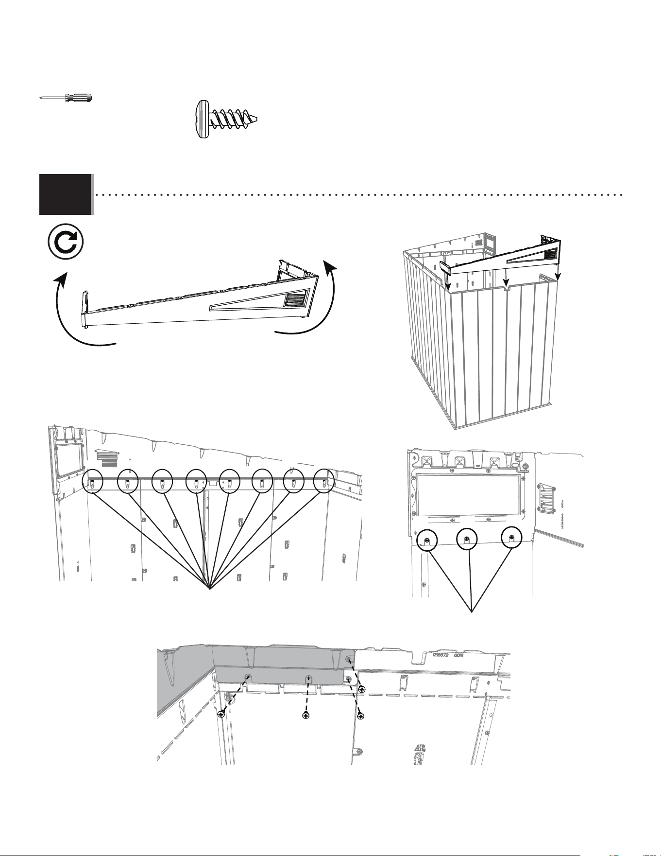
• Complete steps 6.9 - 6.11 to attach the left-side gable.
• Compléter les étapes 6.9-6.11 pour fi xer le pignon du côté gauche.
• Completar los pasos 6.9 a 6.11 para colocar el alero del lado izquierdo.
ADZ (x15)
X 8
X 3
Side of gable / Côté du pignon / Lado del alero
Front of gable / Devant du pignon / Frente del alero
Rear of gable / Arrière du pignon / Parte trasera del alero
ADZ ADZ
ADZ
ADZ
ADZ ADZ ADZ
ADZ
ADZ ADZ
ADZ
ADZ
ADZ
ADZ
ADZ
46
TOOLS AND HARDWARE REQUIRED / OUTILS ET QUINCAILLERIE REQUIS / INSTRUMENTAL Y HERRAJE REQUERIDOS
X SECTION 6 (CONTINUED) / SECTION 6 (SUITE) / SECCIÓN 6 (CONTINUACIÓN)
6.13
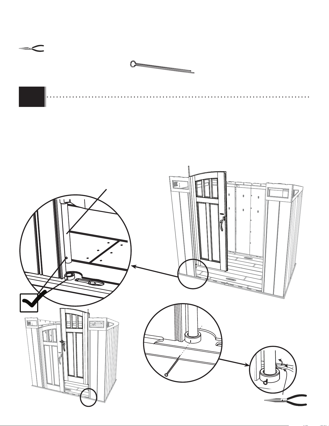
• Pull the hinge tube down out of the left door (the door with hinge tube (FVW), the longest of the tubes) about six inches.
Align the hole at the bottom of the hinge tube with the slit in the bushing, and insert the tube. Insert a cotter pin
(AHP) and bend the ends. Repeat this step for the right door.
• Étendre le tube d’articulation à peu près quinze centimètres du bord inférieur de la porte (la porte avec le tube
de charnière (FVW), le plus long des tubes). Aligner le trou dans la partie inférieure du tube avec la fente dans la bague, et
insérer le tube. Insérer une clavette (AHP) et plier les extrémités. Répéter cette étape pour la porte droite.
• Extender el tubo de articulación unos qunice centimetros del borde inferior de la puerta (la puerta con el tubo
de bisagra (FVW), el más largo de los tubos). Alinear el agujero en la parte inferior del tubo con la rendija en el casquillo, e
insertar el tubo. Insertar una clavija (AHP) y doblar los extremos. Repetir este paso para la puerta derecha.
• Hinge tube (FVW)
• Tube d’articulation (FVW)
• Tubo de articulación (FVW)
AHP
• Hinge tube (FVW)
• Tube d’articulation (FVW)
• Tubo de articulación (FVW)
AHP (x2)
47
TOOLS AND HARDWARE REQUIRED / OUTILS ET QUINCAILLERIE REQUIS / INSTRUMENTAL Y HERRAJE REQUERIDOS
X SECTION 6 (CONTINUED) / SECTION 6 (SUITE) / SECCIÓN 6 (CONTINUACIÓN)
6.14
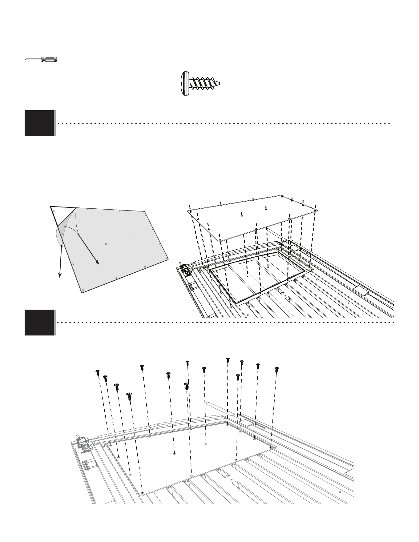
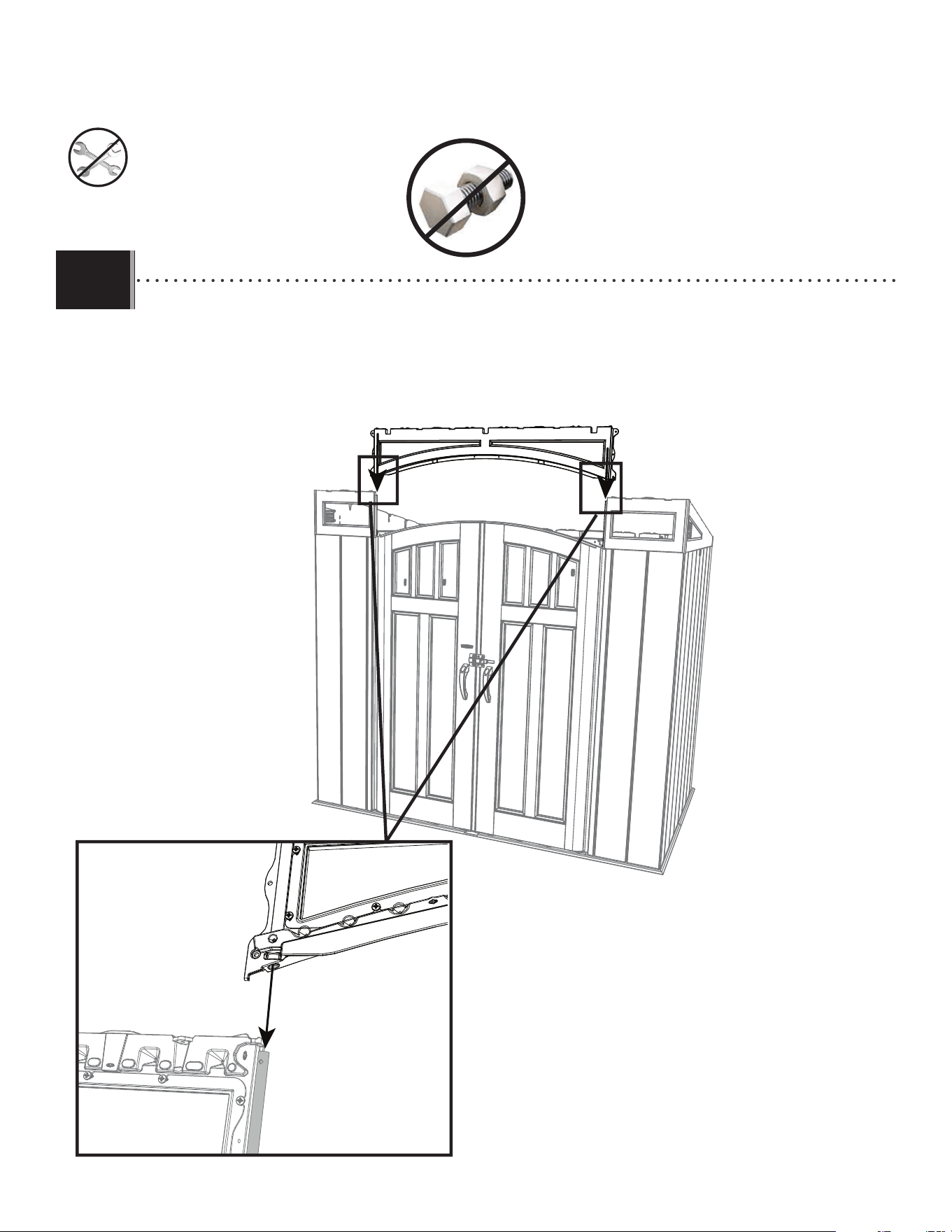
• Slide the holes in the front transom down over the two hinge tubes in the doors. There are holes on the
underside of the transom that will be fi tted over the door’s hinge tubes.
• Faire glisser les trous dans le toit à pignon d’entrée sur les deux tubes. Il y a des trous sous l’imposte qui se-
ront alignés sur les tubes des charnières de la porte.
• Deslizar los agujeros en la fachada de entrada sobre los dos tubos. Hay orifi cios en la parte inferior del
travesaño que se colocarán sobre los tubos de las bisagras de la puerta.
48
TOOLS AND HARDWARE REQUIRED / OUTILS ET QUINCAILLERIE REQUIS / INSTRUMENTAL Y HERRAJE REQUERIDOS
X SECTION 6 (CONTINUED) / SECTION 6 (SUITE) / SECCIÓN 6 (CONTINUACIÓN)
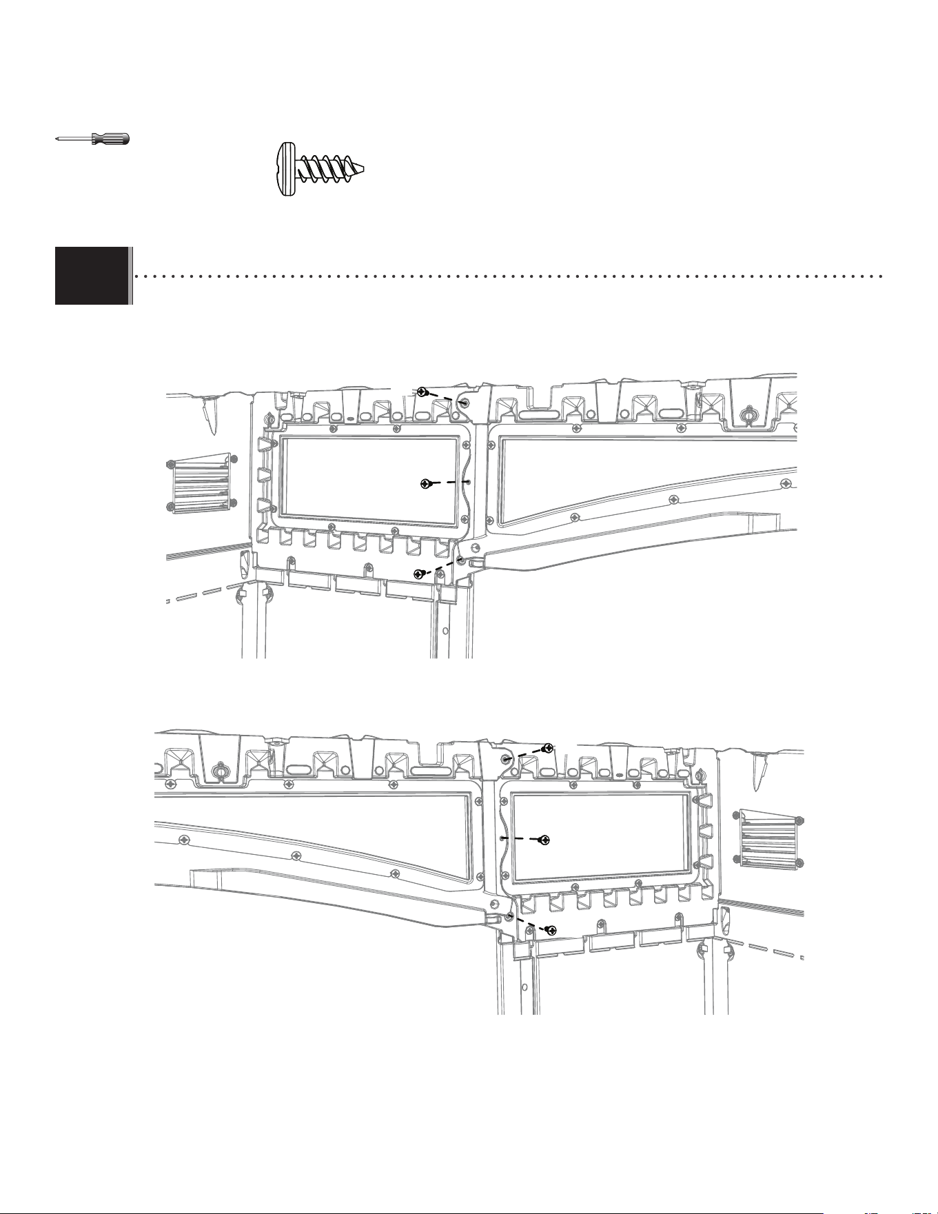
6.15
ADZ (x6)
• Attach both sides of the transom to the left and right gables with the hardware indicated.
• Fixer les deux côtés de l’imposte aux pignons de gauche et de droite avec la quincaillerie indiquée.
• Con el herraje indicado, fi jar ambos lados del travesaño a los aleros izquierdo y derecho.
ADZ
ADZ
ADZ
ADZ
ADZ
ADZ
49
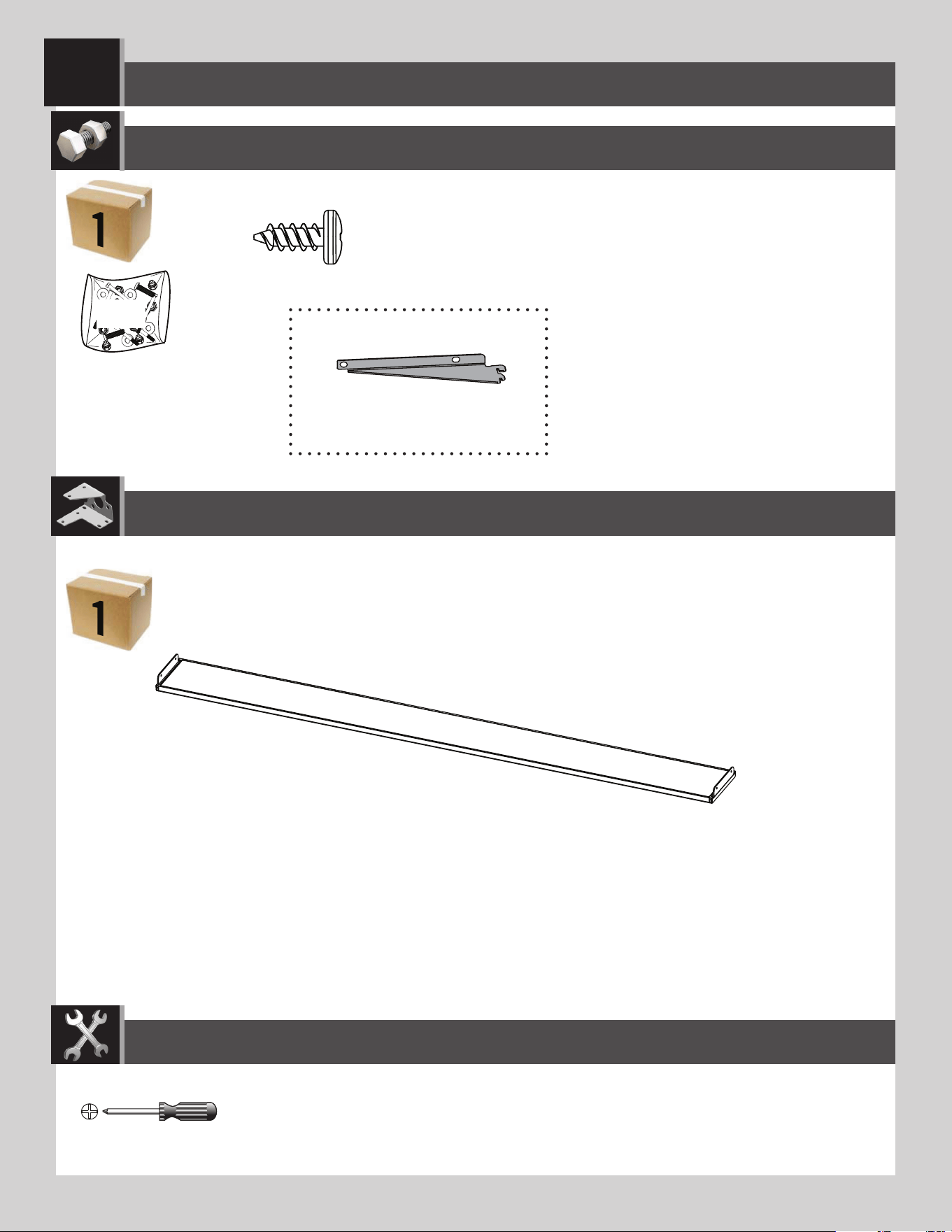
AFV (x1)
Plastic parts / Pièces en plastique / Piezas de plástico
PARTS REQUIRED / PIÈCES REQUISES / PIEZAS REQUERIDAS
HARDWARE REQUIRED / QUINCAILLERIE REQUISE / HERRAJE REQUERIDO
SHELVING INSTALLATION / INSTALLATION DU RAYONNAGE / INSTALACIÓN DE LA ESTANTERÍA
7
ADZ (x14)*
AIY (x2)
FWX
* Not all hardware will be used in the section.
*La quincaillerie n’est pas utilisée au complet dans la section.
*No se utilizará todo el herraje en la sección.
TOOLS REQUIRED / OUTILS REQUIS / INSTRUMENTAL REQUERIDO
(Not included—unless otherwise indicated*) / (Non inclus — sauf indication contraire*) / (No incluido, salvo indicación contraria*)
Parts / Pièces / Piezas
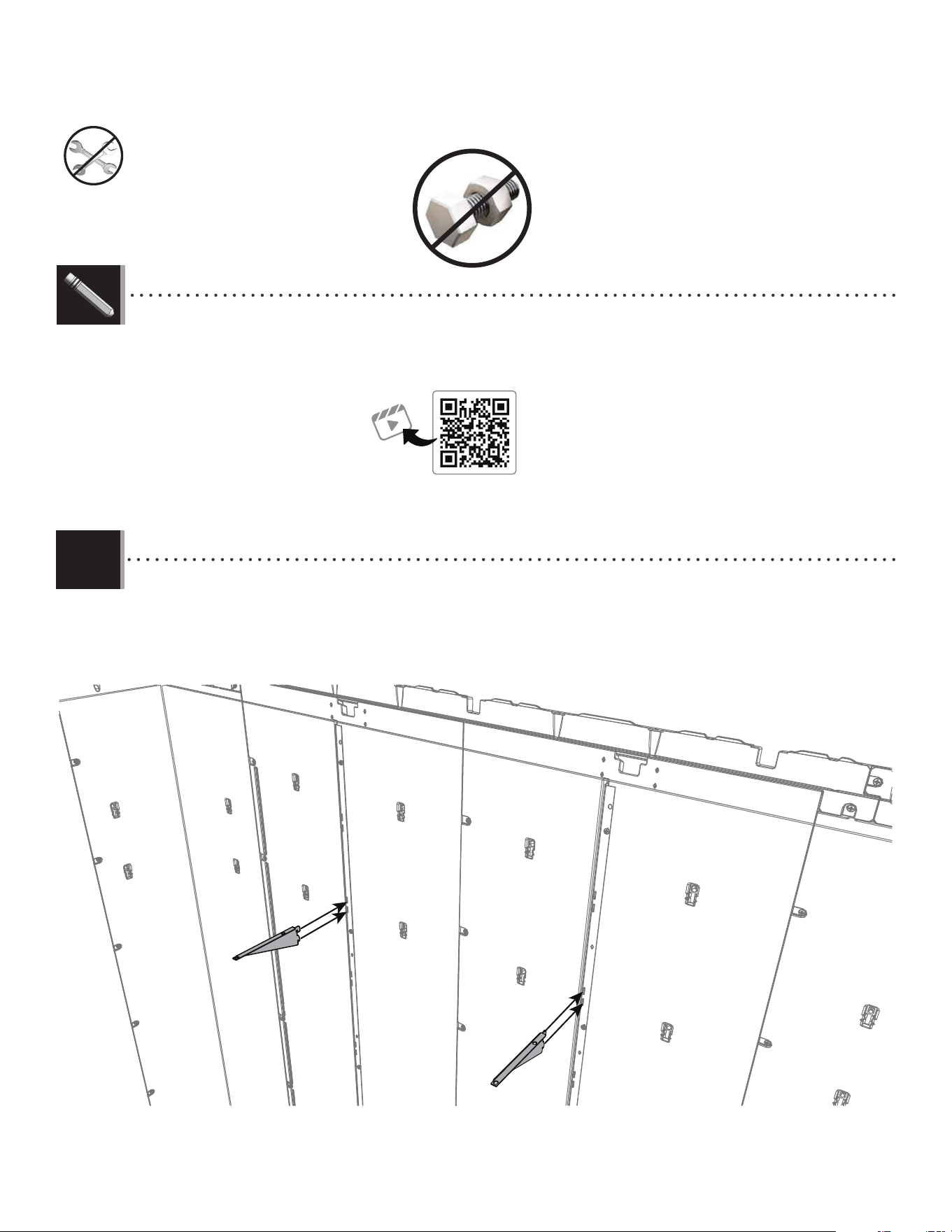
50
TOOLS AND HARDWARE REQUIRED / OUTILS ET QUINCAILLERIE REQUIS / INSTRUMENTAL Y HERRAJE REQUERIDOS
X SECTION 7 (CONTINUED) / SECTION 7 (SUITE) / SECCIÓN 7 (CONTINUACIÓN)
• Insert the shelf brackets (AIY) into the slots in the wall support channels. The brackets must be at the same height.
• Insérer les équerres (AIY) dans les fentes dans les canaux de support muraux. Les équerres doivent être de la même hauteur.
• Insertar las escuadras (AIY) dentro de las ranuras en los canales de soporte murales. Las escuadras deben estar a la misma altura.
AIY
AIY
7.1
http://go.lifetime.com/compactmodernshed-section7
LIFETIME
®
• In case of troubles with this section, scan the QR code below to view a video on its assembly.
• En cas d’avoir des problèmes avec cette section, scanner le code QR en dessous pour voir un vidéo de l’assemblage.
• En caso de tener problemas con esta sección, escanear el código QR debajo para ver un video del ensamblaje.
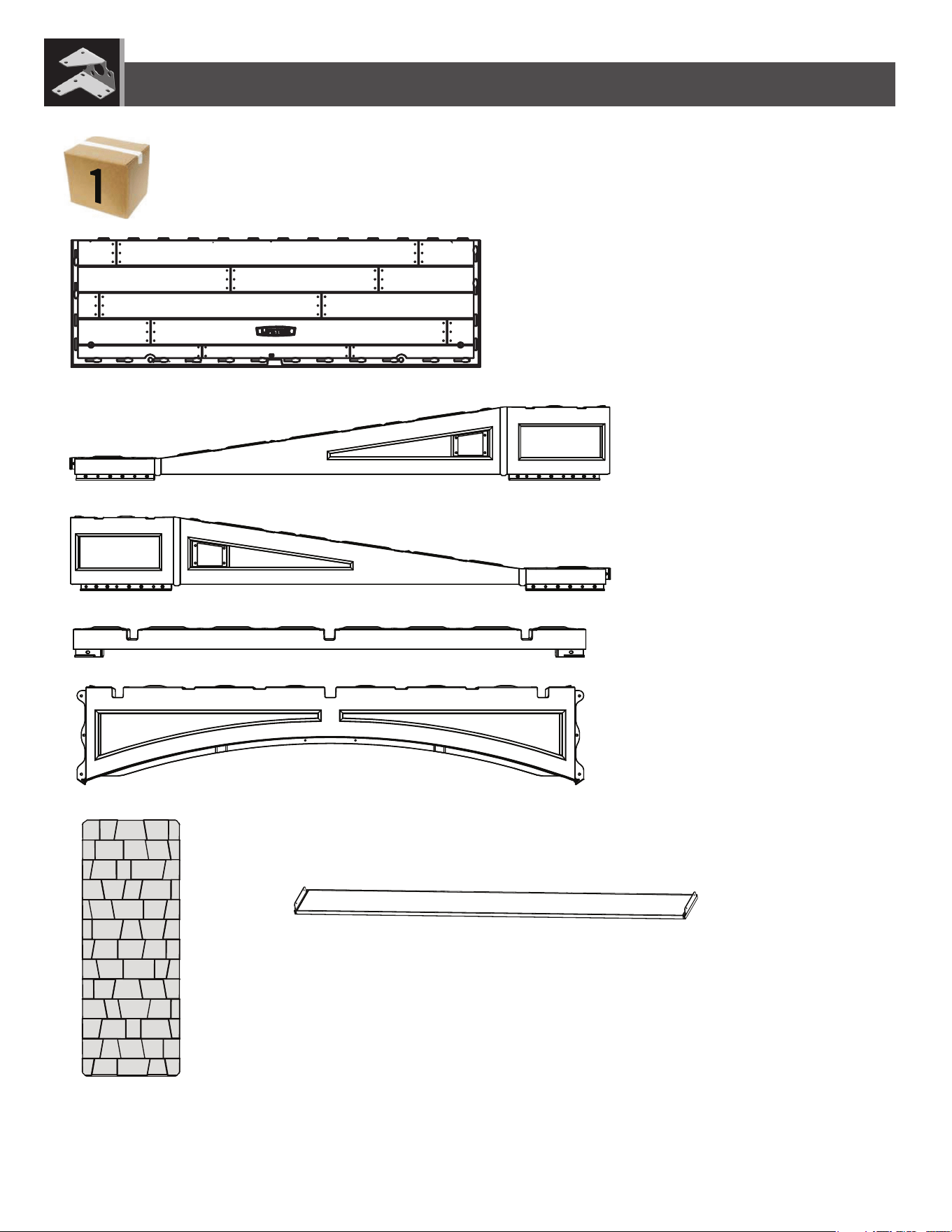
i
CONTENTS OF BOX 1 / CONTENU DE LA BOITE 1 / CONTENIDO DE LA CAJA 1
PARTS IDENTIFIER / IDENTIFICATEUR DE PIÈCES / IDENTIFICADOR DE PIEZAS
Detach this section for quick reference / Détacher cette section pour référence rapide / Despegar esta sección para referencia rápida
CUW (x2)
AFV (x1)
GDU (x1)
GDV (x1)
GDW (x1)
FYG (x4)
GDT (x1)
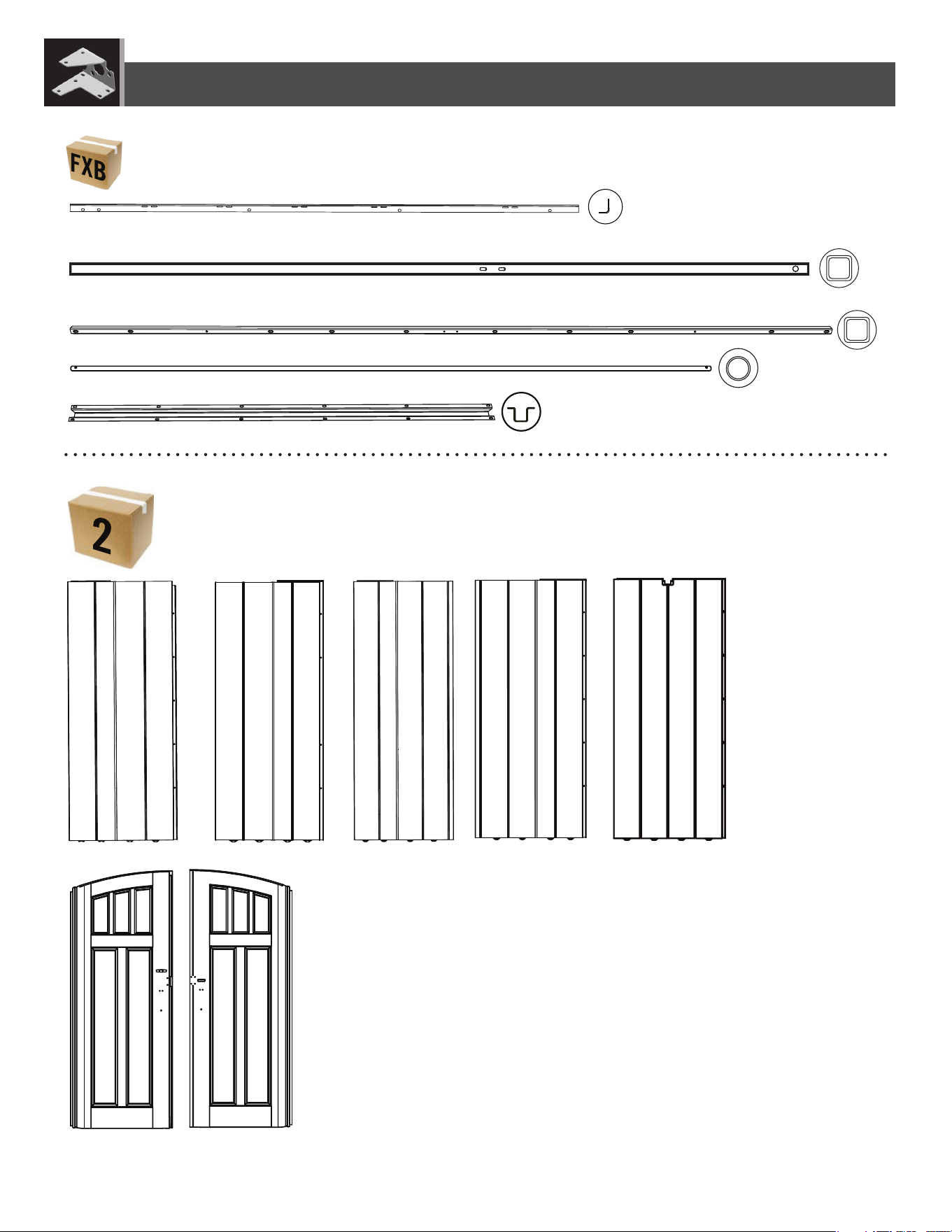
ii
PARTS IDENTIFIER / IDENTIFICATEUR DE PIÈCES / IDENTIFICADOR DE PIEZAS
Detach this section for quick reference / Détacher cette section pour référence rapide / Despegar esta sección para referencia rápida
CONTENTS METAL KIT 1 / CONTENU DE LA TROUSSE DE PIÈCES EN MÉTAL 1 / CONTENIDO DEL KIT DE PIEZAS DE METAL 1
AGW (x1) AGL (x1) AGN (x1) AGY (x1) AHD (x4)
BDK (x1)BDJ (x1)
CONTENTS OF BOX 2 / CONTENU DE LA BOITE 2 / CONTENIDO DE LA CAJA 2
AFM (x6)
EDW (x2)
FVT (x1)
FVW (x2)
FVV (x3)
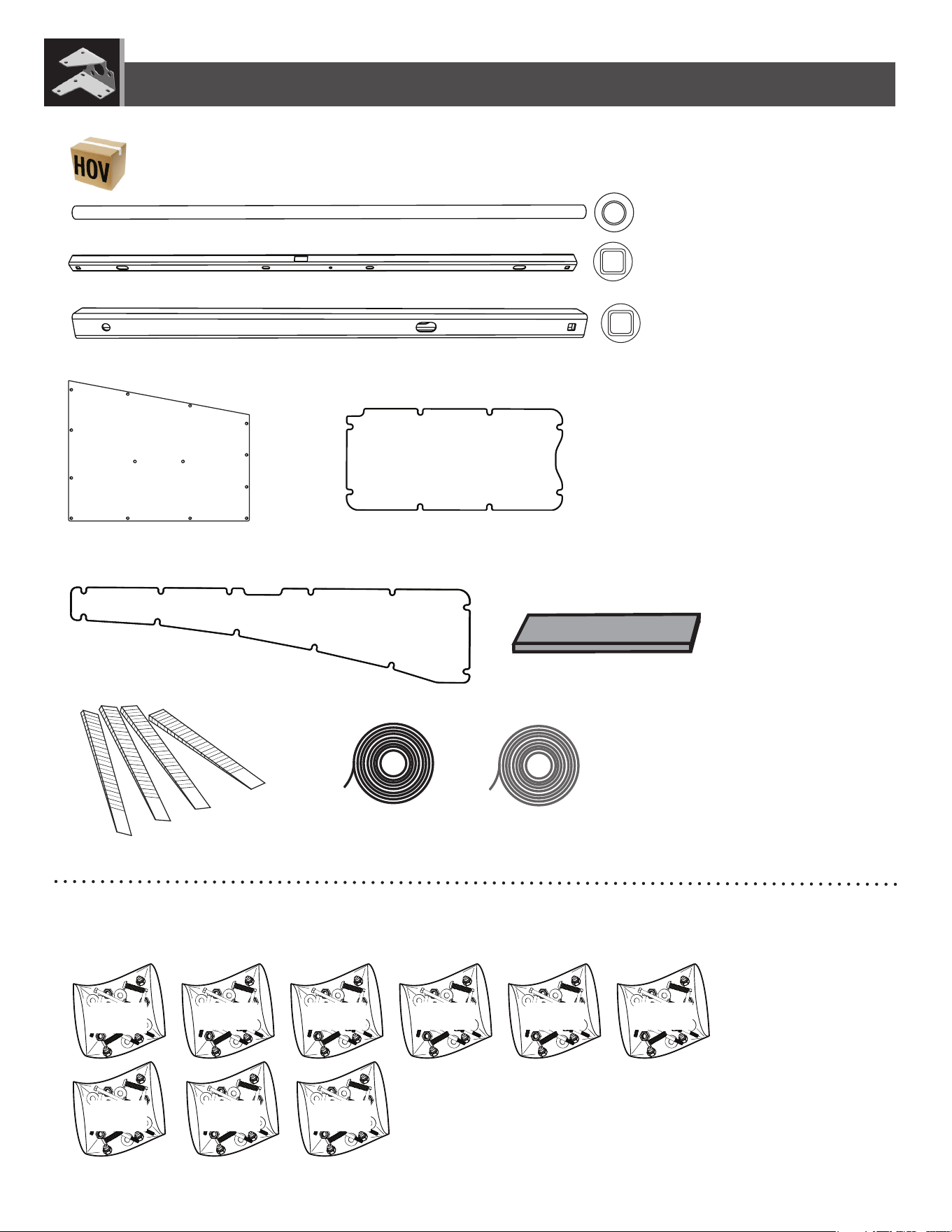
iii
CONTENTS OF SMALL PARTS KIT / CONTENU DE LA TROUSSE DE PETITES PIÈCES / CONTENIDO DEL KIT DE PIEZAS PEQUEÑAS
PARTS IDENTIFIER / IDENTIFICATEUR DE PIÈCES / IDENTIFICADOR DE PIEZAS
Detach this section for quick reference / Détacher cette section pour référence rapide / Despegar esta sección para referencia rápida
DHN (x2)
FWB (x2)
FWC (x2)
EPH (x4) EPI (x1)
AIW (x1)
AIX (x4)
GKX (x8)
FVR (x1)
FVS (x2)
FXA
HARDWARE BAGS / SACS DE QUINCAILLERIE / BOLSAS DE HERRAJE
FWZ FXC FXE FXF FWX
HOU DHL EDH

iv
PARTS IDENTIFIER / IDENTIFICATEUR DE PIÈCES / IDENTIFICADOR DE PIEZAS
Detach this section for quick reference / Détacher cette section pour référence rapide / Despegar esta sección para referencia rápida
THIS PAGE INTENTIONALLY LEFT BLANK
CETTE LPAGE A ÉTÉ INTENTIONNELLEMENT LAISSÉE EN BLANC
ESTA PÁGINA SE HA DEJADO EN BLANCO INTENCIONADAMENTE
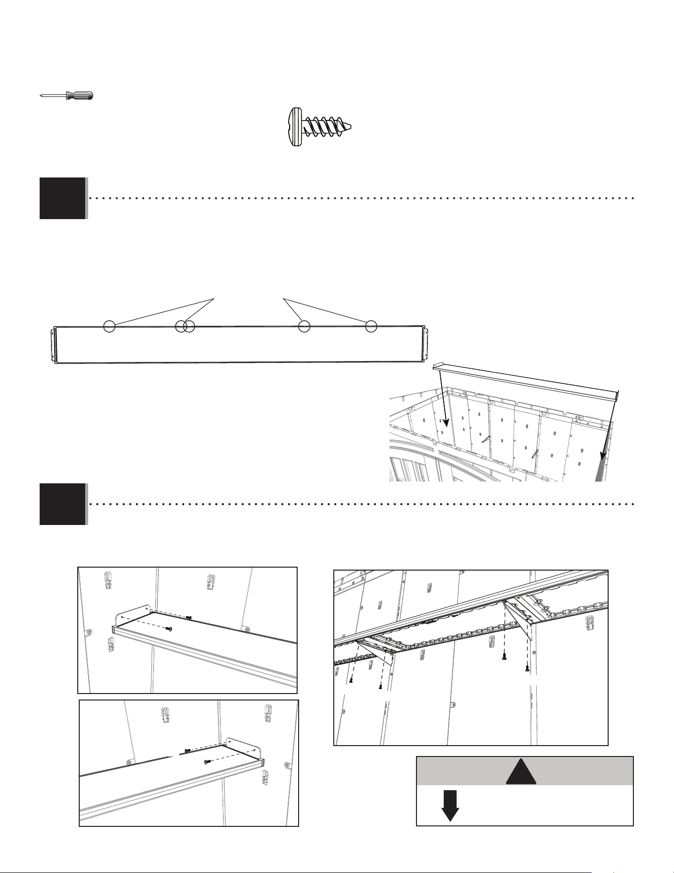
51
TOOLS AND HARDWARE REQUIRED / OUTILS ET QUINCAILLERIE REQUIS / INSTRUMENTAL Y HERRAJE REQUERIDOS
X SECTION 7 (CONTINUED) / SECTION 7 (SUITE) / SECCIÓN 7 (CONTINUACIÓN)
ADZ (x8)
AFV
AFV
50 lb. (≈23 kg)
!
• Attach the shelf (AFV) to the corner wall panels and shelf brackets using eight (8) screws (ADZ).
• Attacher l’étagère (AFV) vers les panneaux muraux de coin et canaux de support muraux en utilisant huit (8) vis (ADZ).
• Sujetar el estante (AFV) a los paneles murales de esquina y las escuadras usando ocho (8) tornillos (ADZ).
• Fold the fl aps on the ends of the shelf (AFV) up, and set the shelf onto the brackets. The notches along the long edge should be
against the rear wall.
• Plier les volets sur les extrémités de l’étagère (AFV) vers le haut, et placer la tablette sur les supports. Les fentes le long de
l’extrémité longue devraient être contre le mur arrière.
• Doblar las aletas del estante (AFV) hacia arriba, y colocar el estante en las escuadras. Las muescas a lo largo del borde largo debe
quedarse contra el muro trasero.
Notches / Fentes / Muescas
7.2
7.3
ADZ
ADZ
ADZ
ADZ
ADZ
ADZ
ADZ
ADZ
AFV
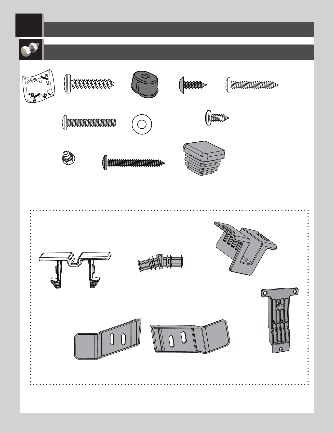
52
HOU
HARDWARE REQUIRED / QUINCAILLERIE REQUISE / HERRAJE REQUERIDO
FEX (x61)
IAU (x64)
GLB (x6)
ADV (x10)
AHS (x2)
ACB (x6)
ROOF ASSEMBLY / MONTAGE DU TOIT / ENSAMBLAJE DEL TECHO
8
FVU (x1)
EYR (x2)
AEE (x2)
ADK (x2)
HDZ (x2)
ADX (x4)
HDX (x2)
HDW (x4)
AIM (x1) AIC (x1)
Parts / Pièces / Piezas
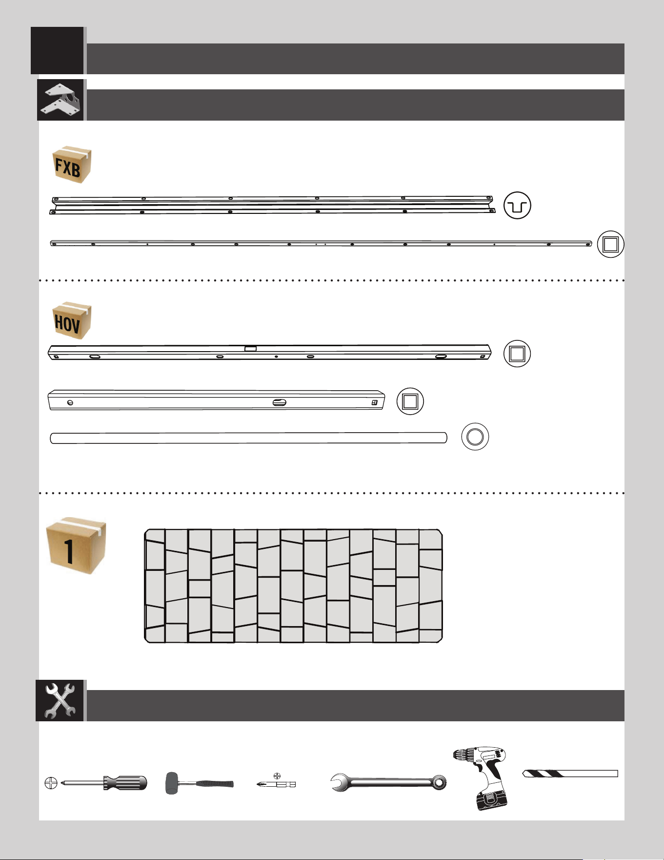
53
PARTS REQUIRED / PIÈCES REQUISES / PIEZAS REQUERIDAS
3/8 in/po (≈10 mm)
ROOF ASSEMBLY / MONTAGE DU TOIT / ENSAMBLAJE DEL TECHO
8
FYG (x4)
Plastic Parts / Pièces en plastique / Piezas de plástico
*GHO 5/32 in/po
(≈4 mm)
TOOLS REQUIRED (NOT INCLUDED—UNLESS INDICATED OTHERWISE*) / OUTILS REQUIS (NON INCLUS—SAUF INDICATION CONTRAIRE*) /
INSTRUMENTAL REQUERIDO (NO INCLUIDO, SALVO INDICACIÓN CONTRARIA*)
FVT (x1)
Metal parts / Pièces en métal / Piezas de metal
GKX (x8)
FVV (x3)
FVR (x1)
FVS (x2)
Metal parts / Pièces en métal / Piezas de metal
TOOLS REQUIRED / OUTILS REQUIS / INSTRUMENTAL REQUERIDO
(Not included—unless otherwise indicated*) / (Non inclus — sauf indication contraire*) / (No incluido, salvo indicación contraria*)
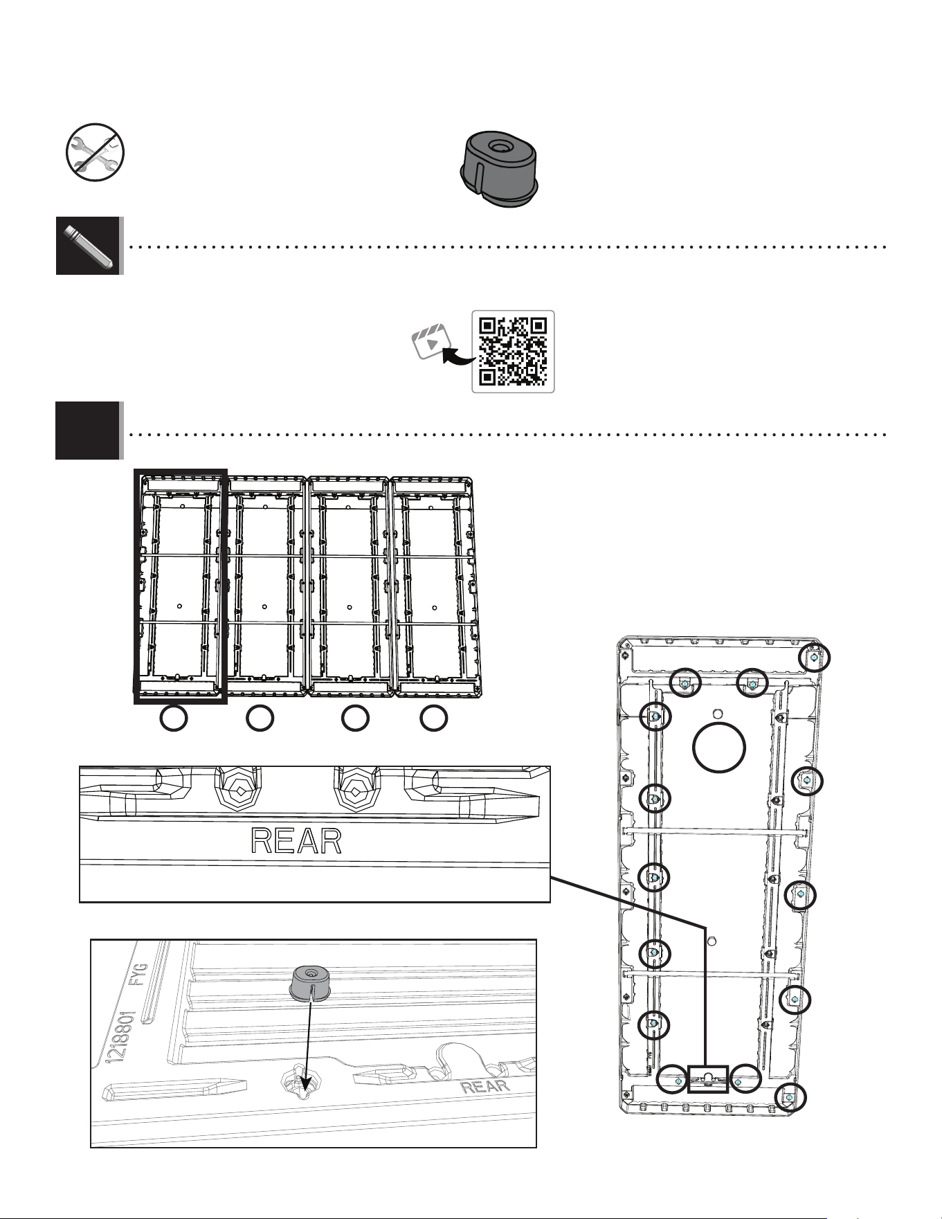
54
X SECTION 8 (CONTINUED) / SECTION 8 (SUITE) / SECCIÓN 8 (CONTINUACIÓN)
TOOLS AND HARDWARE REQUIRED / OUTILS ET QUINCAILLERIE REQUIS / INSTRUMENTAL Y HERRAJE REQUERIDOS
FEX
8.1
• Snap fourteen (14) anchors (FEX) in the direction shown into
only the slots indicated in this roof panel (FYG). DO NOT REPEAT this
step for the other three (3) roof panels.
• Enclencher quatorze (14)ancrages (FEX) dans la direction
indiquée seulement dans les fentes indiquées dans ce
panneau de toit (FYG). NE PAS RÉPÉTER cette étape pour les trois (3)panneaux
de toit restants.
• Encajar catorce (14) anclajes (FEX) en la dirección que se
muestra solo en las ranuras indicadas en este panel de techo
(FYG). NO REPETIR este paso para los otros tres (3) paneles del techo.
FEX (x14)
1
2 3 41
FYG
Panel #1 / Panneau n
o
1 / panel n. ° 1
http://go.lifetime.com/compactmodernshed-section8
LIFETIME
®
• In case of troubles with this section, scan the QR code below to view a video on its assembly.
• En cas d’avoir des problèmes avec cette section, scanner le code QR en dessous pour voir un vidéo de l’assemblage.
• En caso de tener problemas con esta sección, escanear el código QR debajo para ver un video del ensamblaje.
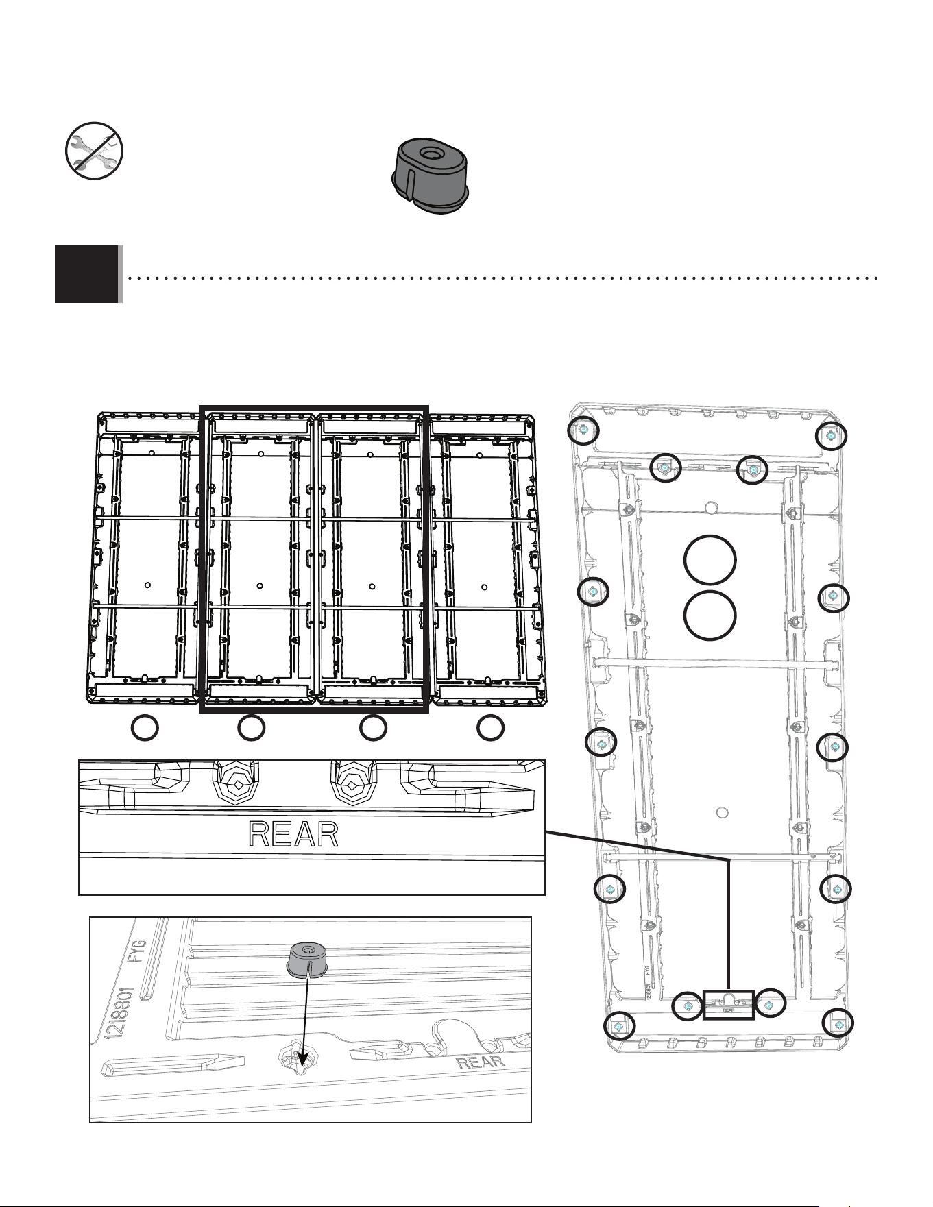
55
X SECTION 8 (CONTINUED) / SECTION 8 (SUITE) / SECCIÓN 8 (CONTINUACIÓN)
TOOLS AND HARDWARE REQUIRED / OUTILS ET QUINCAILLERIE REQUIS / INSTRUMENTAL Y HERRAJE REQUERIDOS
8.2
• Snap fourteen (14) anchors (FEX) in the direction shown into only the slots indicated in this roof panel (FYG). Complete this step
for the second and third panels only.
• Enclencher quatorze (14)ancrages (FEX) dans la direction indiquée seulement dans les fentes indiquées dans ce
panneau de toit (FYG). Compléter cette étape pour les deuxième et troisième panneaux seulement.
• Encajar catorce (14) anclajes (FEX) en la dirección que se muestra solo en las ranuras indicadas en este panel de techo
(FYG). Completar este paso solo para el segundo y tercer panel.
FEX (x28)
2 3 41
2
FEX
3
FYG
Panel #2 & 3 / Panneau n
o
2 & 3 / panel n. ° 2 & 3
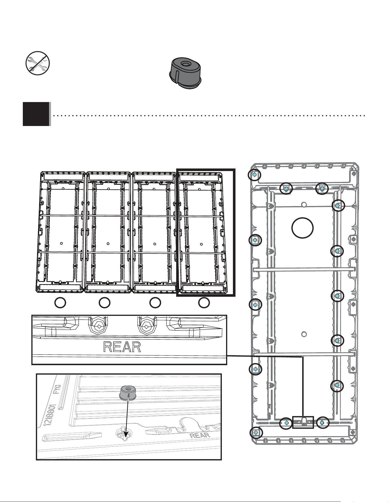
56
X SECTION 8 (CONTINUED) / SECTION 8 (SUITE) / SECCIÓN 8 (CONTINUACIÓN)
TOOLS AND HARDWARE REQUIRED / OUTILS ET QUINCAILLERIE REQUIS / INSTRUMENTAL Y HERRAJE REQUERIDOS
8.3
• Snap fourteen (14) anchors (FEX) in the direction shown into only the slots indicated in this roof panel (FYG).
• Enclencher quatorze (14)ancrages (FEX) dans la direction indiquée seulement dans les fentes indiquées dans ce panneau
de toit (FYG).
• Encajar catorce (14) anclajes (FEX) en la dirección que se muestra solo en las ranuras indicadas en este panel de techo (FYG).
FEX (x14)
2 3 41
4
FEX
FYG
Panel #4 / Panneau n
o
4 / panel n. ° 4
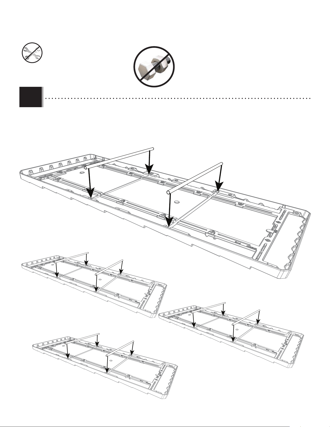
57
X SECTION 8 (CONTINUED) / SECTION 8 (SUITE) / SECCIÓN 8 (CONTINUACIÓN)
TOOLS AND HARDWARE REQUIRED / OUTILS ET QUINCAILLERIE REQUIS / INSTRUMENTAL Y HERRAJE REQUERIDOS
8.4
• Snap two (2) roof support tubes (GKX) into the recesses on the underside of the roof panel. Repeat this step for the remaining three
(3) roof panels.
• Enclencher deux (2)tubes de soutien de toit (GKX) dans les renfoncements sur le dessous du panneau de toit. Répéter cette
étape pour les trois (3)panneaux de toit restants.
• Encajar dos (2) tubos de soporte del techo (GKX) en los agujeros en la parte inferior del panel del techo. Repetir este paso para los
tres (3) paneles del techo restantes.
GKX
GKX
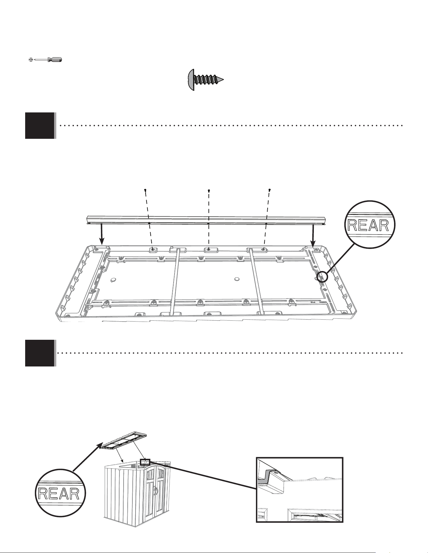
58
X SECTION 8 (CONTINUED) / SECTION 8 (SUITE) / SECCIÓN 8 (CONTINUACIÓN)
TOOLS AND HARDWARE REQUIRED / OUTILS ET QUINCAILLERIE REQUIS / INSTRUMENTAL Y HERRAJE REQUERIDOS
8.5
IAU (x3)
FYG
Panel #1 / Panneau n
o
1 / panel n. ° 1
• Place a gutter channel (FVV) on the right side of the fi rst roof panel (FYG). Secure the gutter channel at the middle three (3) screw
anchors with the hardware indicated.
• Placer une gouttière (FVV) du côté droit du premier panneau de toit (FYG). Bien attacher la gouttière aux trois (3)vis d’ancrage du
milieu avec la quincaillerie indiquée.
• Colocar un canalón (FVV) en el lado derecho del primer panel de techo (FYG). Asegurar bien el canalón en los tres (3) anclajes de
tornillo del medio con el herraje indicado.
FVV
IAU IAU IAU
8.6
• Using two (2) adults, place the fi rst roof panel onto the left side of the shed. Line up the gutter channel into the carve-
outs in the shed. Be sure the roof panel facing the back of the shed has the word REAR on the underside of the panel.
• À l’aide de deux (2)adultes, placer le premier panneau de toit sur le côté gauche de la remise. Aligner la gouttière
avec les rainures dans la remise. Vérifi er que le panneau de toit positionné vers l’arrière de la remise porte bien le mot
REAR (ARRIÈRE) en dessous du panneau.
• Con ayuda de dos (2) adultos, colocar el primer panel del techo en el lado izquierdo de la caseta. Alinear el canalón
con los huecos en el cobertizo. Asegurarse de que el panel del techo que mira hacia la parte posterior de la caseta
tenga la palabra REAR (TRASERO) en la parte inferior del panel.
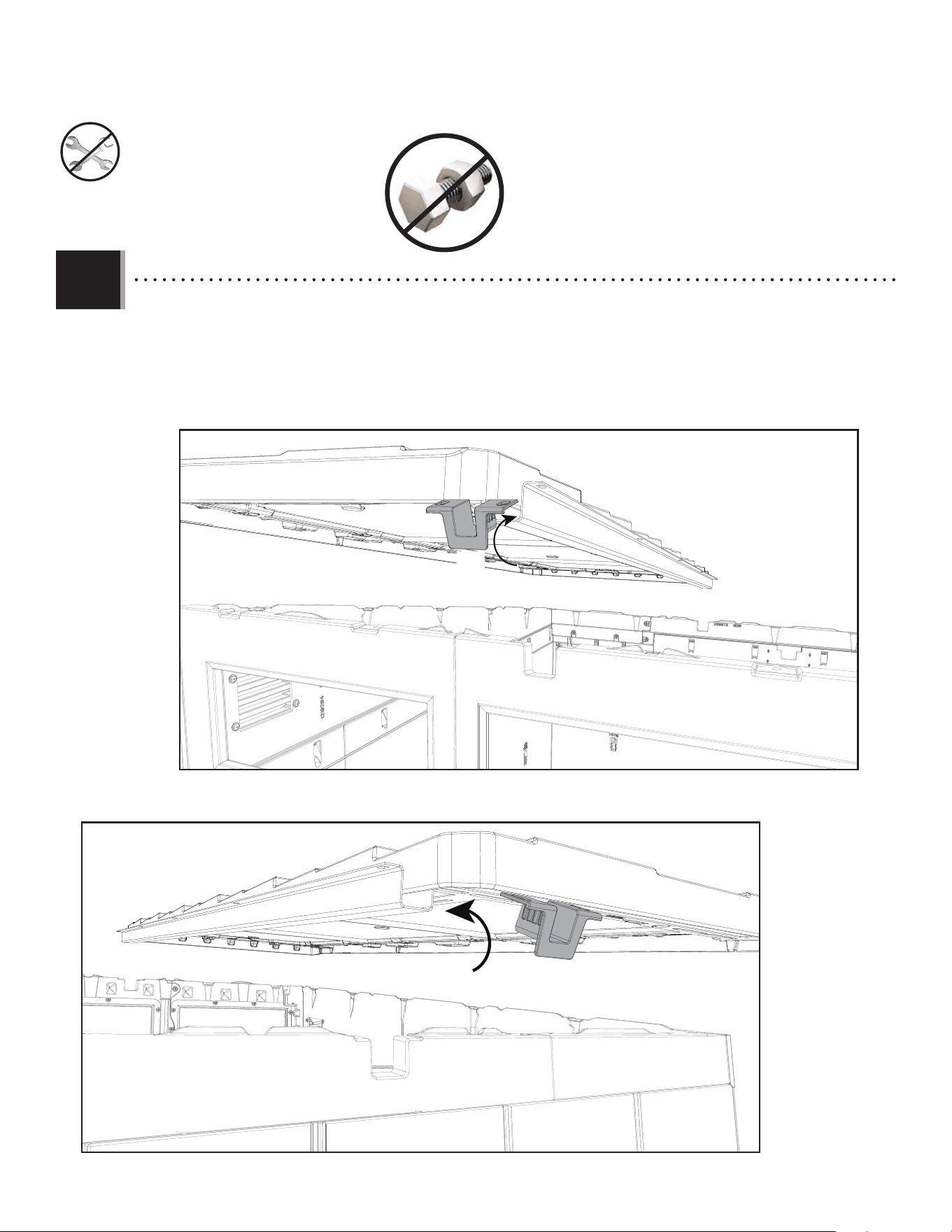
59
X SECTION 8 (CONTINUED) / SECTION 8 (SUITE) / SECCIÓN 8 (CONTINUACIÓN)
TOOLS AND HARDWARE REQUIRED / OUTILS ET QUINCAILLERIE REQUIS / INSTRUMENTAL Y HERRAJE REQUERIDOS
8.7
• To insert one (1) gutter channel cover (GLB) into each end of a gutter channel, slightly tilt the cover upon insertion. Press it over
the channel but under the roof panel.
• Pour insérer un (1) couvercle pour le canal de gouttière (GLB) dans chaque extrémité du canal de gouttière, incliner légèrement la
couverture lor de l’insertion. Presser la couverture sur le canal mais sou le panneau de toit.
• Para insertar una (1) cubierta para el canal de desagüe (GLB) en cada extremo del canal de desagüe, inclinar ligeramente la
cubierta al insertarla. Presionarlas encima del canal mas debajo del panel de techo.
Front view
Vue avant
Vista delantera
Rear view
Vue arrière
Vista trasera
GLB
GLB
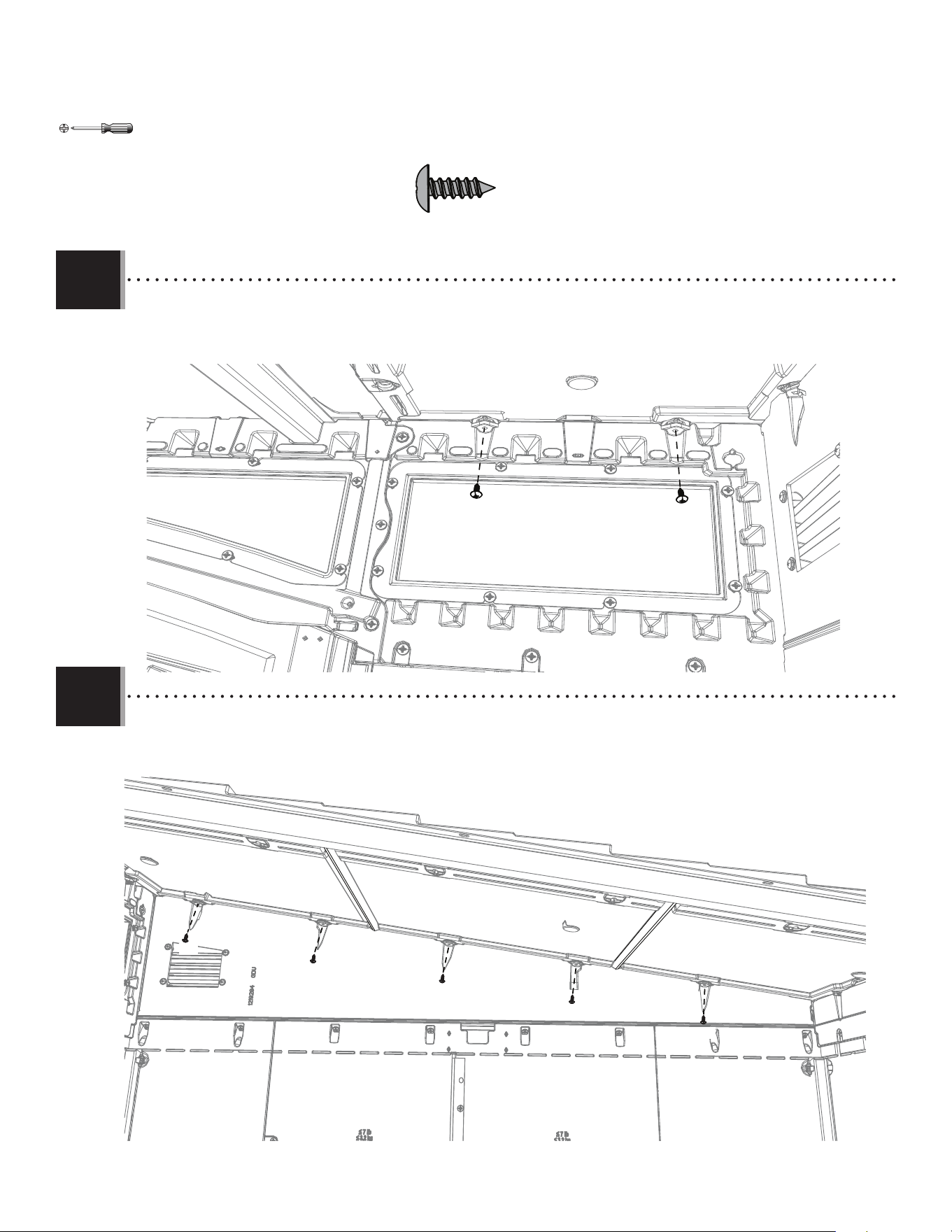
60
X SECTION 8 (CONTINUED) / SECTION 8 (SUITE) / SECCIÓN 8 (CONTINUACIÓN)
TOOLS AND HARDWARE REQUIRED / OUTILS ET QUINCAILLERIE REQUIS / INSTRUMENTAL Y HERRAJE REQUERIDOS
8.8
• Attach the front of the fi rst roof panel with the hardware indicated.
• Fixer l’avant du premier panneau de toit avec la quincaillerie indiquée.
• Fijar la parte delantera del primer panel del techo con el herraje indicado.
IAU (x7)
IAU
IAU
8.9
• Attach the side of the fi rst roof panel with the hardware indicated.
• Fixer le côté du premier panneau de toit avec la quincaillerie indiquée.
• Fijar la parte lateral del primer panel del techo con el herraje indicado.
IAU
IAU
IAU
IAU
IAU
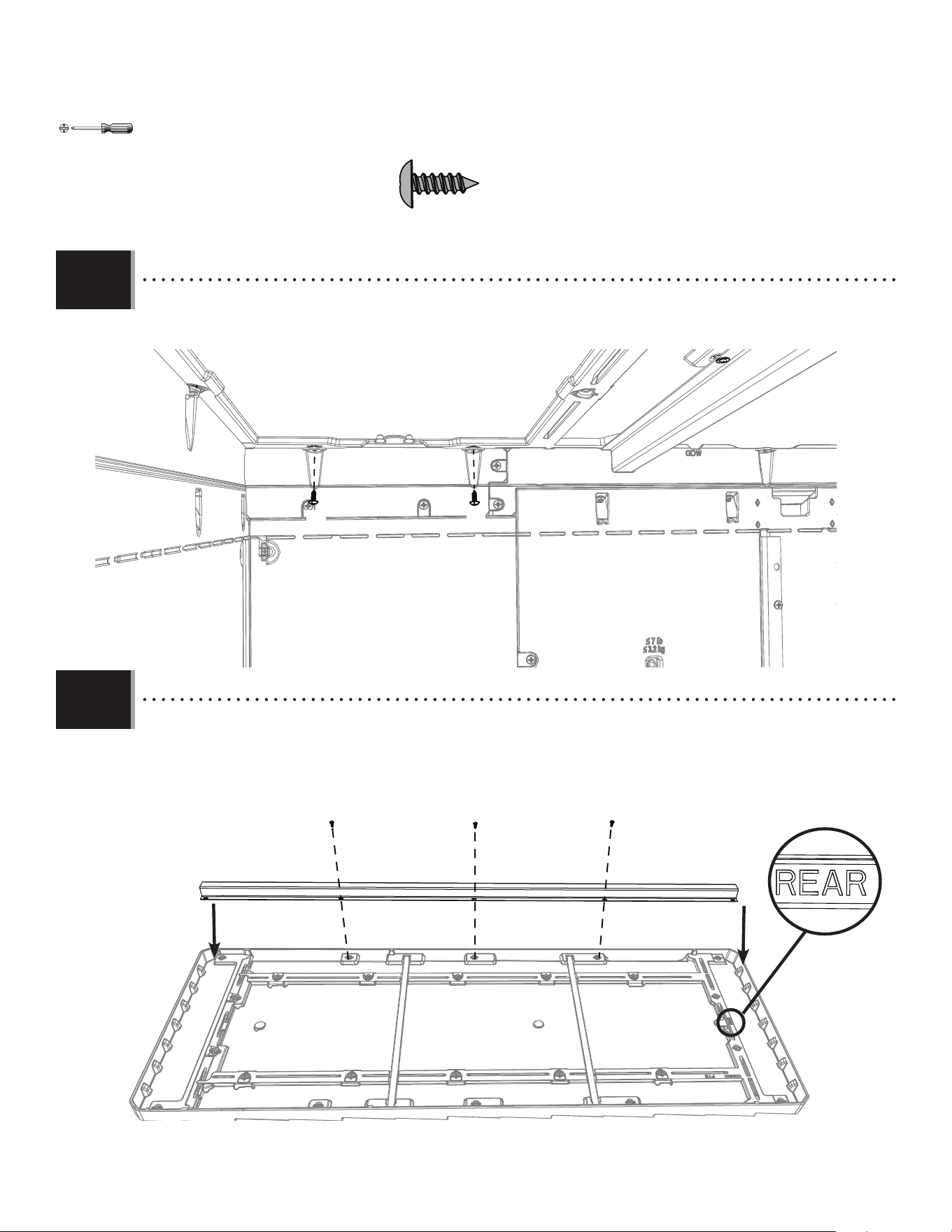
61
X SECTION 8 (CONTINUED) / SECTION 8 (SUITE) / SECCIÓN 8 (CONTINUACIÓN)
TOOLS AND HARDWARE REQUIRED / OUTILS ET QUINCAILLERIE REQUIS / INSTRUMENTAL Y HERRAJE REQUERIDOS
8.10
• Attach the back of the fi rst roof panel with the hardware indicated.
• Fixer l’arrière du premier panneau de toit avec la quincaillerie indiquée.
• Fijar la parte trasera del primer panel del techo con el herraje indicado.
IAU (x5)
IAU IAU
8.11
• Place a gutter channel (FVV) on the right side of the second roof panel (FYG). Secure the gutter channel at the middle three
(3) screw anchors with the hardware indicated.
• Placer une gouttière (FVV) du côté droit du deuxième panneau de toit (FYG). Attacher la gouttière aux trois (3)vis
d’ancrage du milieu avec la quincaillerie indiquée.
• Colocar un canalón (FVV) en el lado derecho del segundo panel de techo (FYG). Asegurar el canalón en los tres (3) anclajes
de tornillo del medio con el herraje indicado.
FVV
IAU IAU IAU
FYG
Panel #2 / FYG – Panneau n
o
2 / FYG: panel n. ° 2
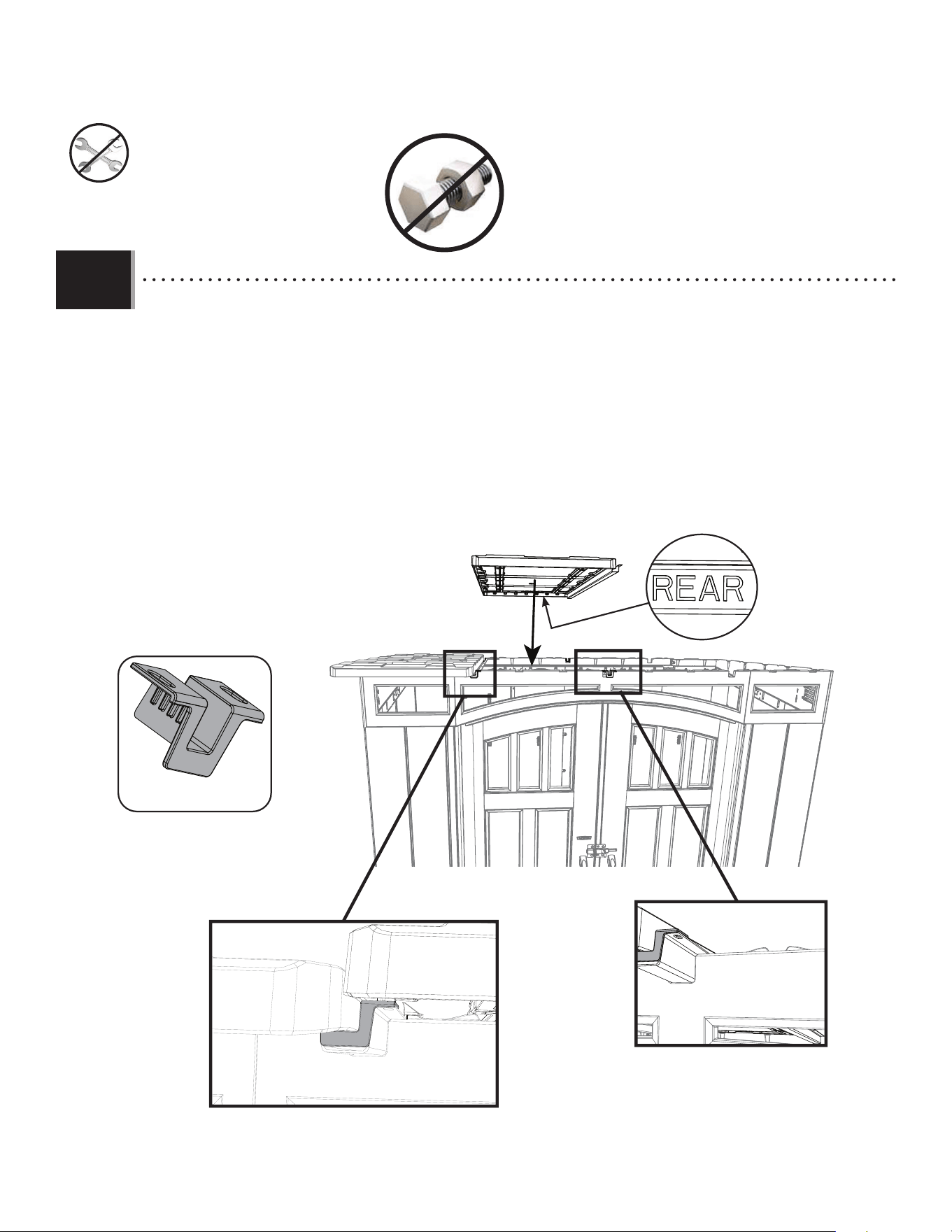
62
X SECTION 8 (CONTINUED) / SECTION 8 (SUITE) / SECCIÓN 8 (CONTINUACIÓN)
TOOLS AND HARDWARE REQUIRED / OUTILS ET QUINCAILLERIE REQUIS / INSTRUMENTAL Y HERRAJE REQUERIDOS
8.12
• Using two (2) adults, place the second roof panel onto the gutter channel of the fi rst roof panel. Add two (2) gutter channel
covers at each end of the second roof panel. Line up the gutter channel of the second roof panel into the carve-outs in the shed. Be
sure the roof panel facing the back of the shed has the word REAR in it on the underside of the panel.
• À l’aide de deux (2)adultes, placer le deuxième panneau de toit sur la gouttière du premier panneau de toit. Ajouter
deux (2) couvertures pour les canaux de guttière à chaque extrémité du deuxième panneau de toit. Aligner la gouttière du deuxième panneau de toit
avec les rainures dans la remise. Vérifi er que le panneau de toit positionné vers l’arrière de la remise porte bien le mot
REAR (ARRIÈRE) en dessous du panneau.
• Con la ayuda de dos (2) adultos, coloque el segundo panel del techo en el canalón del primer panel del techo. Añadir
dos (2) cubiertas para los canales de desagüe a cada extremo del segundo panel de techo. Alinear el canalón del segundo panel del techo con los
agujeros en el cobertizo. Asegurarse de que el panel del techo que mira hacia la parte posterior de la caseta tenga la
palabra REAR (TRASERO) en la parte inferior del panel.
GLB (x2)
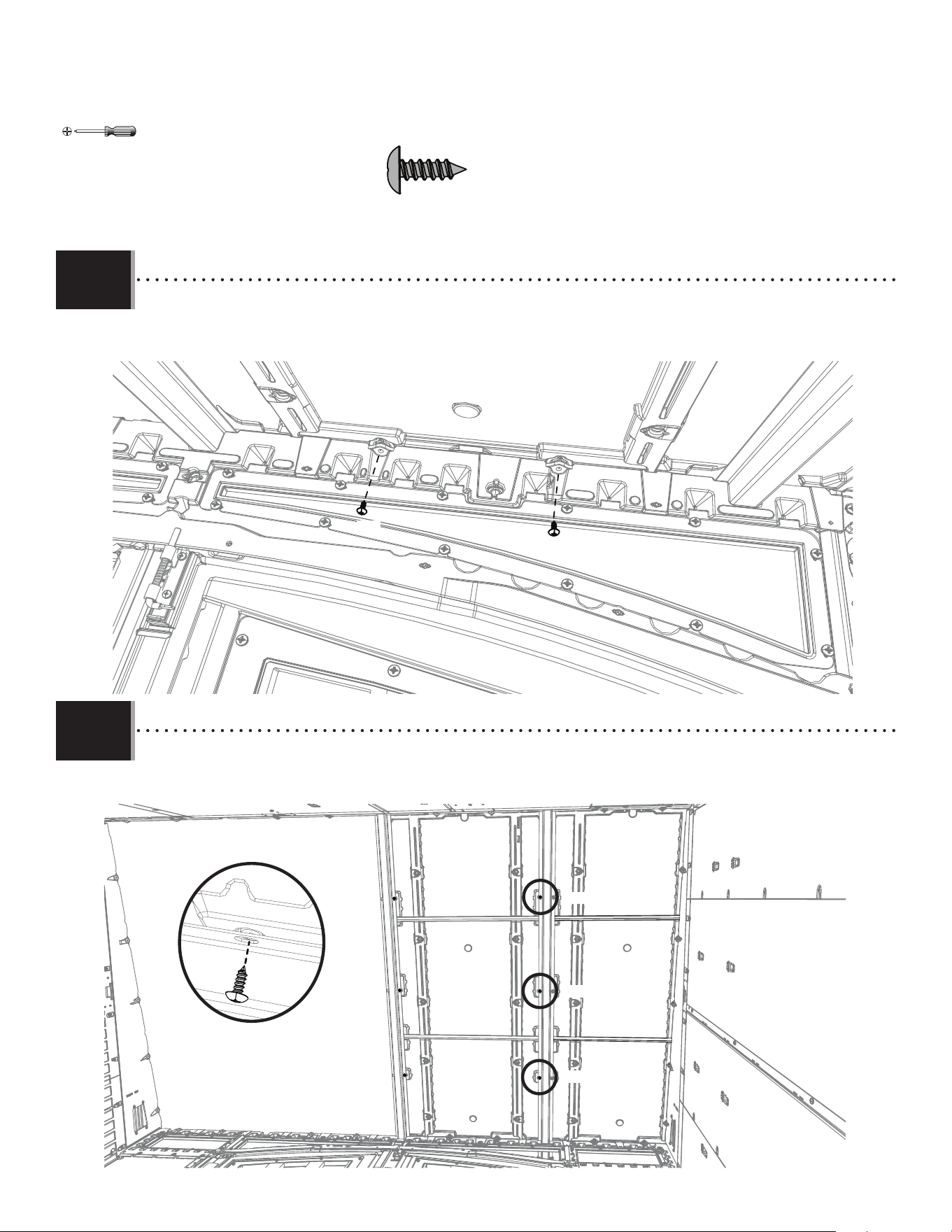
63
X SECTION 8 (CONTINUED) / SECTION 8 (SUITE) / SECCIÓN 8 (CONTINUACIÓN)
TOOLS AND HARDWARE REQUIRED / OUTILS ET QUINCAILLERIE REQUIS / INSTRUMENTAL Y HERRAJE REQUERIDOS
8.13
• Attach the front of the second roof panel with the hardware indicated.
• Fixer l’avant du deuxième panneau de toit avec la quincaillerie indiquée.
• Fijar la parte delantera del segundo panel del techo con el herraje indicado.
IAU
IAU
IAU (x5)
8.14
• Attach the middle of the second roof panel with the hardware indicated.
• Fixer le milieu du deuxième panneau de toit avec la quincaillerie indiquée.
• Fijar la parte media del segundo panel del techo con el herraje indicado.
IAU
IAU
IAU
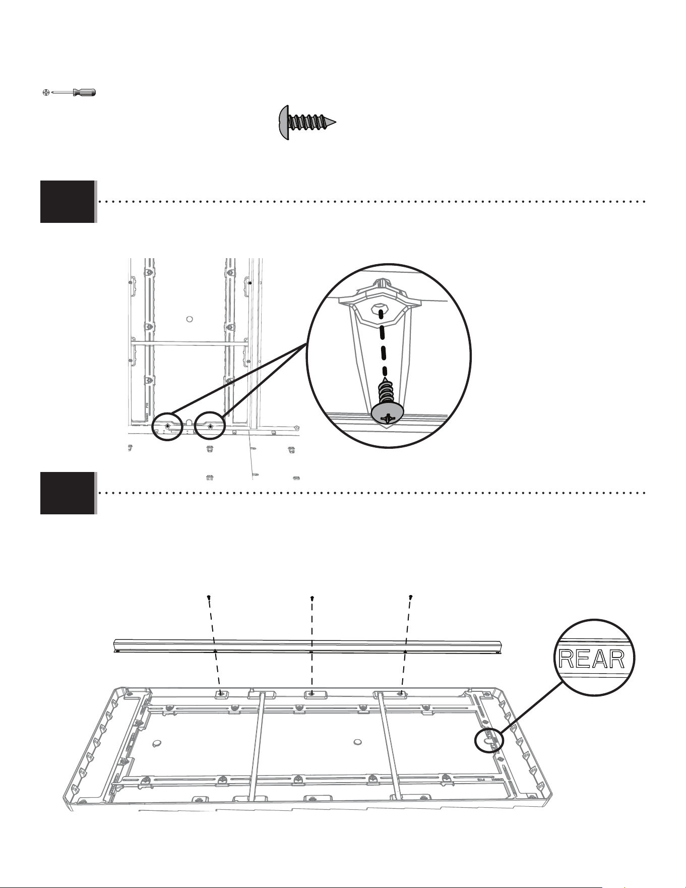
64
X SECTION 8 (CONTINUED) / SECTION 8 (SUITE) / SECCIÓN 8 (CONTINUACIÓN)
TOOLS AND HARDWARE REQUIRED / OUTILS ET QUINCAILLERIE REQUIS / INSTRUMENTAL Y HERRAJE REQUERIDOS
8.15
• Attach the back of the second roof panel with the hardware indicated.
• Fixer l’arrière du deuxième panneau de toit avec la quincaillerie indiquée.
• Fijar la parte trasera del segundo panel del techo con el herraje indicado.
IAU (x5)
IAU
• Place a gutter channel (FVV) on the right side of the third roof panel (FYG). Secure the gutter channel at the middle three (3)
screw anchors with the hardware indicated.
• Placer une gouttière (FVV) du côté droit du troisième panneau de toit (FYG). Attacher la gouttière aux trois (3)vis d’ancrage du
milieu avec la quincaillerie indiquée.
• Colocar un canalón (FVV) en el lado derecho del tercer panel de techo (FYG). Asegurar el canalón en los tres (3) anclajes de
tornillo del medio con el herraje indicado.
8.16
IAU
IAU
IAU
FYG
Panel #3 / Panneau n
o
3 / panel n. ° 3
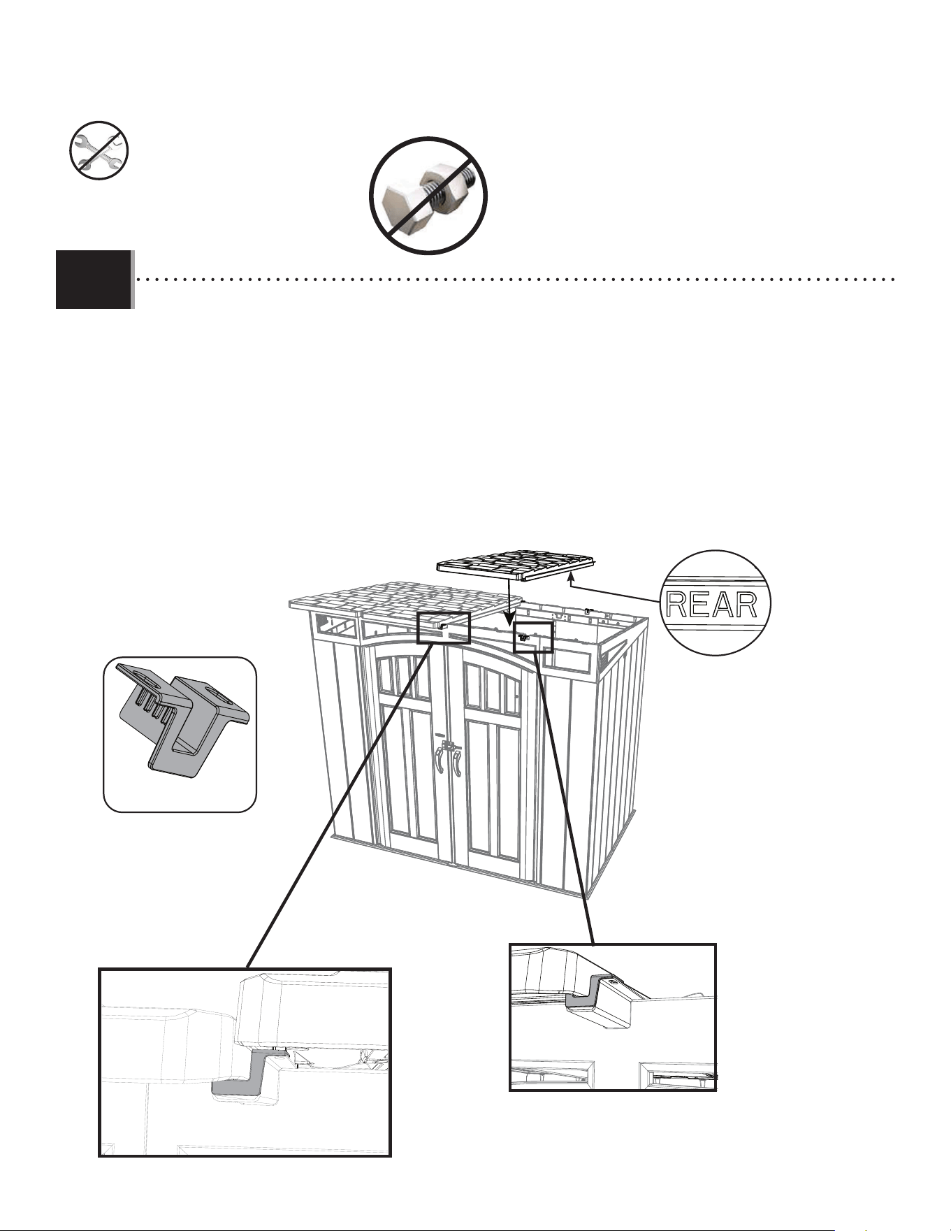
65
X SECTION 8 (CONTINUED) / SECTION 8 (SUITE) / SECCIÓN 8 (CONTINUACIÓN)
TOOLS AND HARDWARE REQUIRED / OUTILS ET QUINCAILLERIE REQUIS / INSTRUMENTAL Y HERRAJE REQUERIDOS
8.17
• Using two (2) adults, place the third roof panel onto the gutter channel of the second roof panel. Add two (2) gutter channel
covers at each end of the second roof panel.Line up the gutter channel of the third roof panel into the carve-outs in the shed. Be
sure the roof panel facing the back of the shed has the word REAR in it on the underside of the panel.
• À l’aide de deux (2)adultes, placer le troisième panneau de toit sur la gouttière du deuxième panneau de toit. Ajouter
deux (2) couvertures pour les canaux de guttière à chaque extrémité du deuxième panneau de toit. Aligner la gouttière du troisième panneau de toit
avec les rainures dans la remise. Vérifi er que le panneau de toit positionné vers l’arrière de la remise porte bien le mot
REAR (ARRIÈRE) en dessous du panneau.
• Con la ayuda de dos (2) adultos, colocar el tercer panel del techo en el canalón del segundo panel del techo. Añadir
dos (2) cubiertas para los canales de desagüe a cada extremo del segundo panel de techo. Alinear el canalón del tercer panel del techo con los
agujeros en el cobertizo. Asegurarse de que el panel del techo que mira hacia la parte posterior de la caseta tenga la
palabra REAR (TRASERO) en la parte inferior del panel.
GLB (x2)
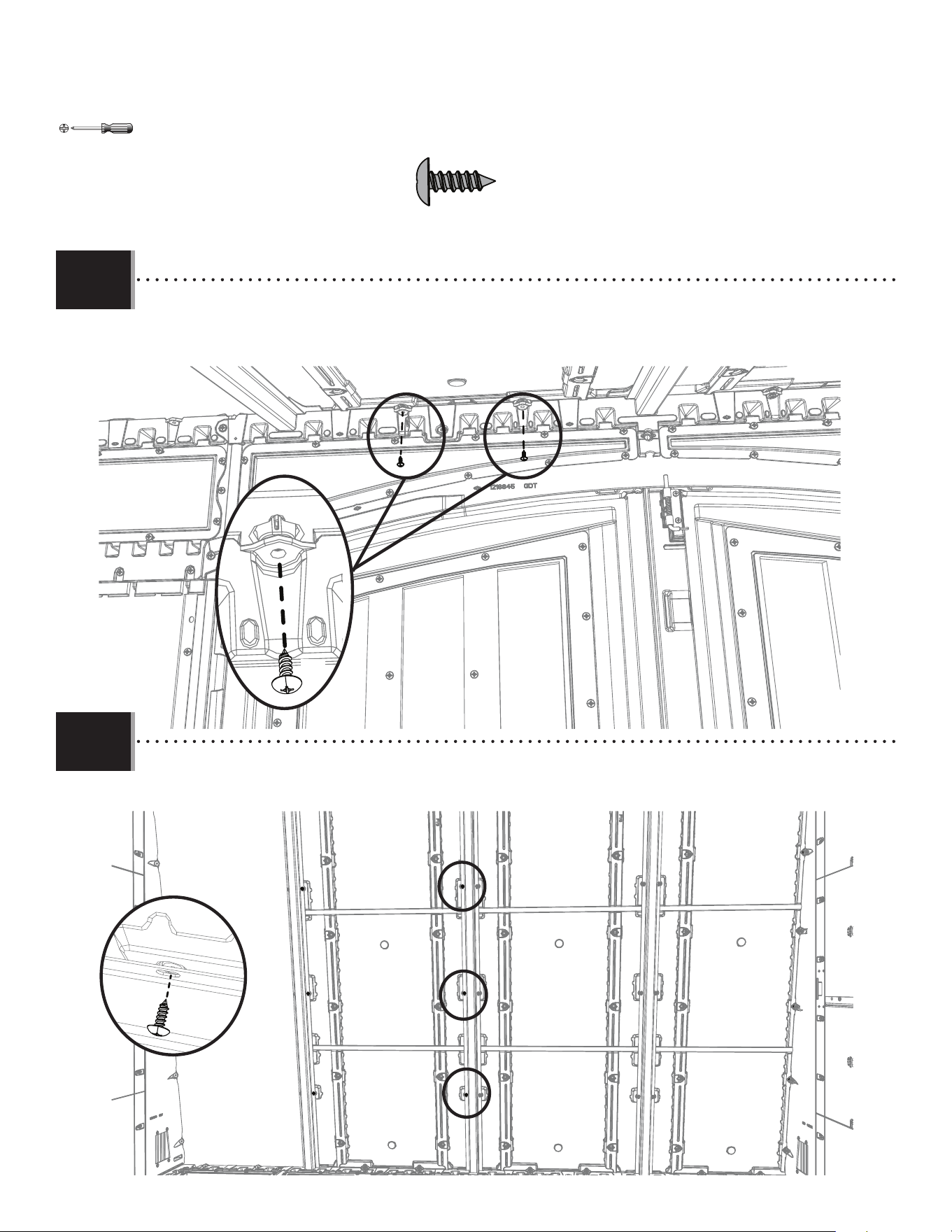
66
X SECTION 8 (CONTINUED) / SECTION 8 (SUITE) / SECCIÓN 8 (CONTINUACIÓN)
TOOLS AND HARDWARE REQUIRED / OUTILS ET QUINCAILLERIE REQUIS / INSTRUMENTAL Y HERRAJE REQUERIDOS
8.18
• Attach the front of the third roof panel with the hardware indicated.
• Fixer l’avant du troisième panneau de toit avec la quincaillerie indiquée.
• Fijar la parte delantera del tercer panel del techo con el herraje indicado.
IAU (x5)
8.19
• Attach the middle of the third roof panel with the hardware indicated.
• Fixer le milieu du troisième panneau de toit avec la quincaillerie indiquée.
• Fijar la parte media del tercer panel del techo con el herraje indicado.
IAU x3
IAU
IAU
IAU
IAU
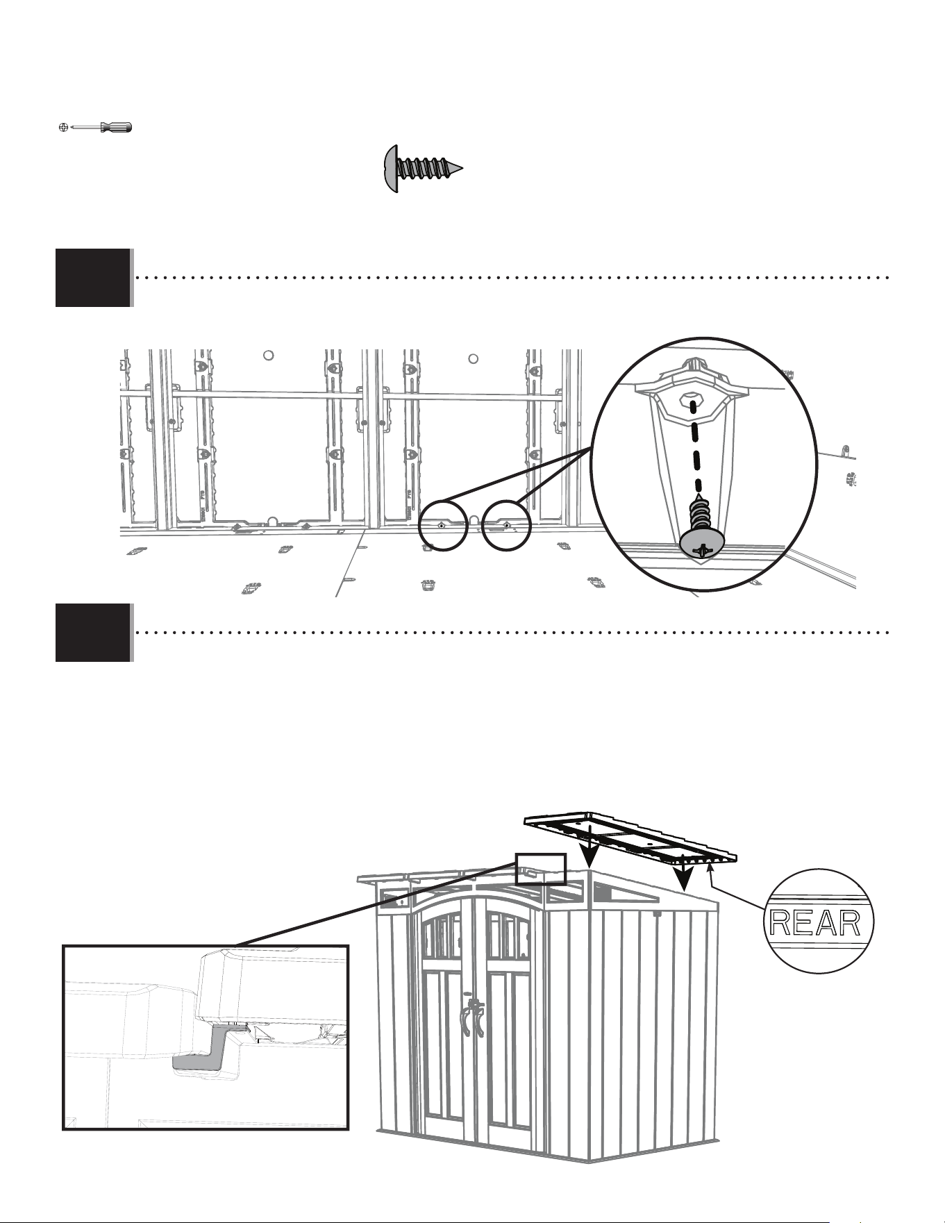
67
X SECTION 8 (CONTINUED) / SECTION 8 (SUITE) / SECCIÓN 8 (CONTINUACIÓN)
TOOLS AND HARDWARE REQUIRED / OUTILS ET QUINCAILLERIE REQUIS / INSTRUMENTAL Y HERRAJE REQUERIDOS
8.20
• Attach the back of the third roof panel with the hardware indicated.
• Fixez l’arrière du troisième panneau de toit avec la quincaillerie indiquée.
• Fijar la parte trasera del tercer panel del techo con el herraje indicado.
IAU (x2)
8.21
• Using two (2) adults, place the fourth roof panel onto the gutter channel of the third roof panel. Be sure the roof panel
facing the back of the shed has the word REAR in it on the underside of the panel. This last panel will not have a
gutter channel installed on it.
• À l’aide de deux (2)adultes, placer le quatrième panneau de toit sur la gouttière du troisième panneau de toit.
Vérifi er que le panneau de toit positionné vers l’arrière de la remise porte bien le mot REAR (ARRIÈRE) en dessous du
panneau. Il n’y aura pas de gouttière installée sur ce dernier panneau.
• Con la ayuda de dos (2) adultos, colocar el cuarto panel del techo en el canalón del tercer panel del techo.
Asegurarse de que el panel del techo que mira hacia la parte posterior de la caseta tenga la palabra REAR
(TRASERO) en la parte inferior del panel. Este último panel no tendrá un canalón instalado.
IAU
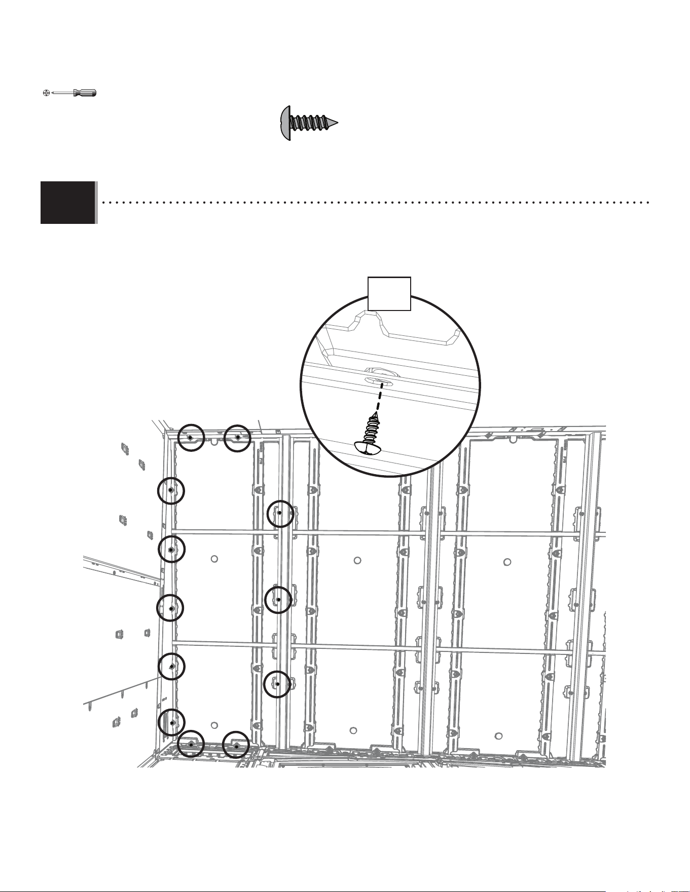
68
X SECTION 8 (CONTINUED) / SECTION 8 (SUITE) / SECCIÓN 8 (CONTINUACIÓN)
TOOLS AND HARDWARE REQUIRED / OUTILS ET QUINCAILLERIE REQUIS / INSTRUMENTAL Y HERRAJE REQUERIDOS
8.22
IAU (x12)
• Attach the fourth roof panel with the hardware indicated.
• Fixer le quatrième panneau de toit avec la quincaillerie indiquée.
• Fijar el cuarto panel del techo con el herraje indicado.
IAU
x12
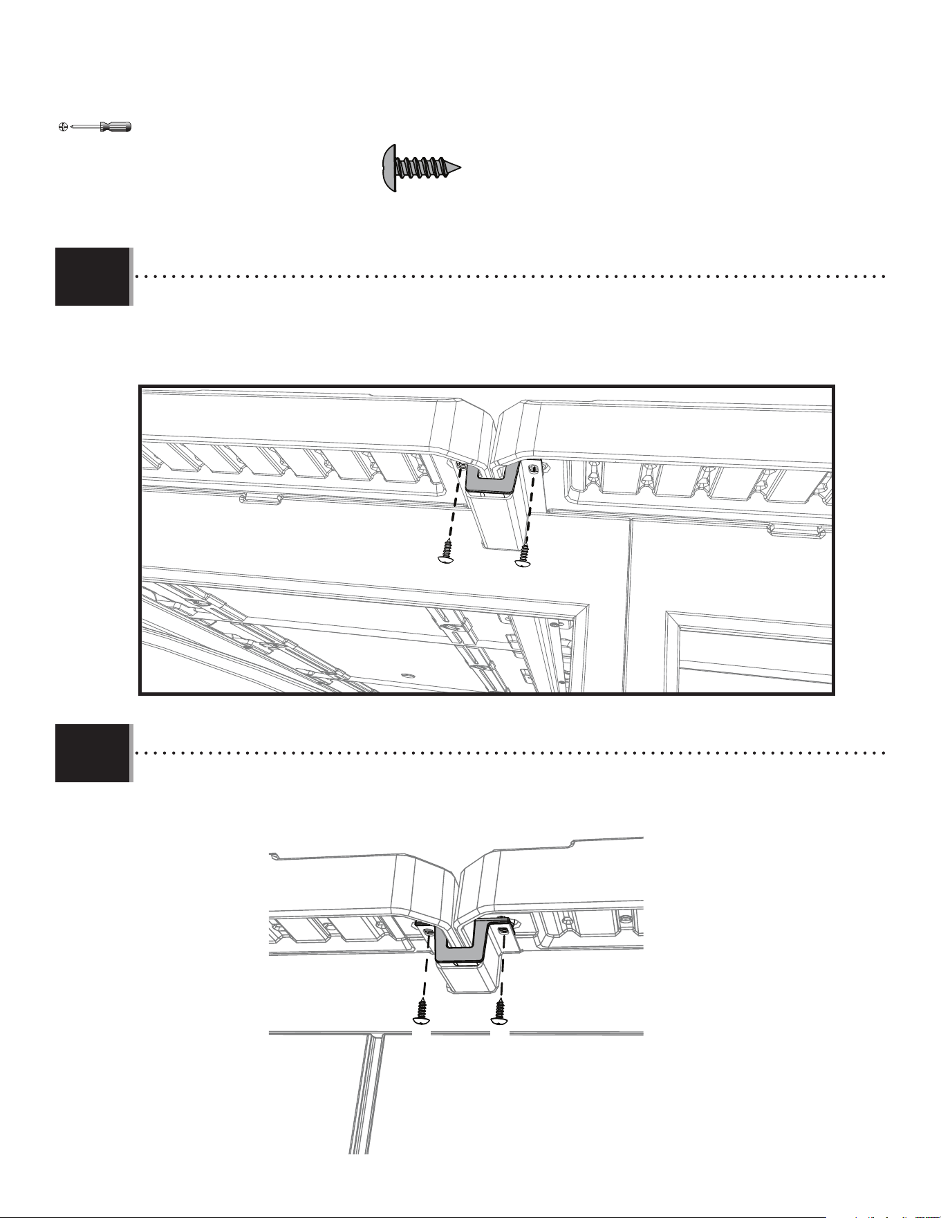
69
X SECTION 8 (CONTINUED) / SECTION 8 (SUITE) / SECCIÓN 8 (CONTINUACIÓN)
TOOLS AND HARDWARE REQUIRED / OUTILS ET QUINCAILLERIE REQUIS / INSTRUMENTAL Y HERRAJE REQUERIDOS
8.23
• Attach the gutter channel covers (GLB) at the front of the shed with the hardware indicated.
• Attacher les couvertures des canaux de guttière (GLB) à l’avant de la caseta à l’aide de la quincaillerie indiquée.
• Sujetar las cubiertas de los canales de desagüe (GLB) a la parte delantera de la caseta usando el herraje indicado.
IAU (x12)
IAU
IAU
8.24
• Attach the gutter channel covers (GLB) at the rear of the shed with the hardware indicated.
• Attacher les couvertures des canaux de guttière (GLB) à l’arrière de la caseta à l’aide de la quincaillerie indiquée.
• Sujetar las cubiertas de los canales de desagüe (GLB) a la parte trasera de la caseta usando el herraje indicado.
IAUIAU
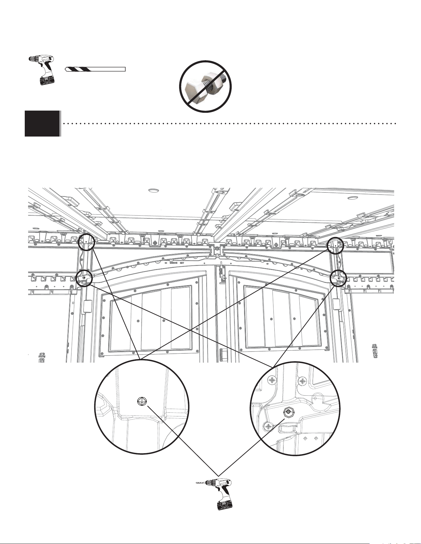
70
X SECTION 8 (CONTINUED) / SECTION 8 (SUITE) / SECCIÓN 8 (CONTINUACIÓN)
TOOLS AND HARDWARE REQUIRED / OUTILS ET QUINCAILLERIE REQUIS / INSTRUMENTAL Y HERRAJE REQUERIDOS
8.25
• Use the 5/32” (5 mm) drill bit to drill through the transom divots and into the hinge tubes. Do not drill all the way through the tubes
and out the transom. Only drill into the front side of the hinge tube.
• Employer un foret de 5/32 po (≈4 mm) pour percer les marques dans l’imposte et dans le tube de charnière. Ne pas
percer complètement l’imposte et les tubes. Ne percer que la face avant du tube des charnières.
• Usar una broca de 5/32 in (≈4 mm) para taladrar las marcas en el montante y en los tubos de bisagra. No taladrar por
completo el montante y los tubos. Perforar sólo en la parte delantera del tubo de la bisagra.
GHO 5/32 in/po (≈4 mm)*
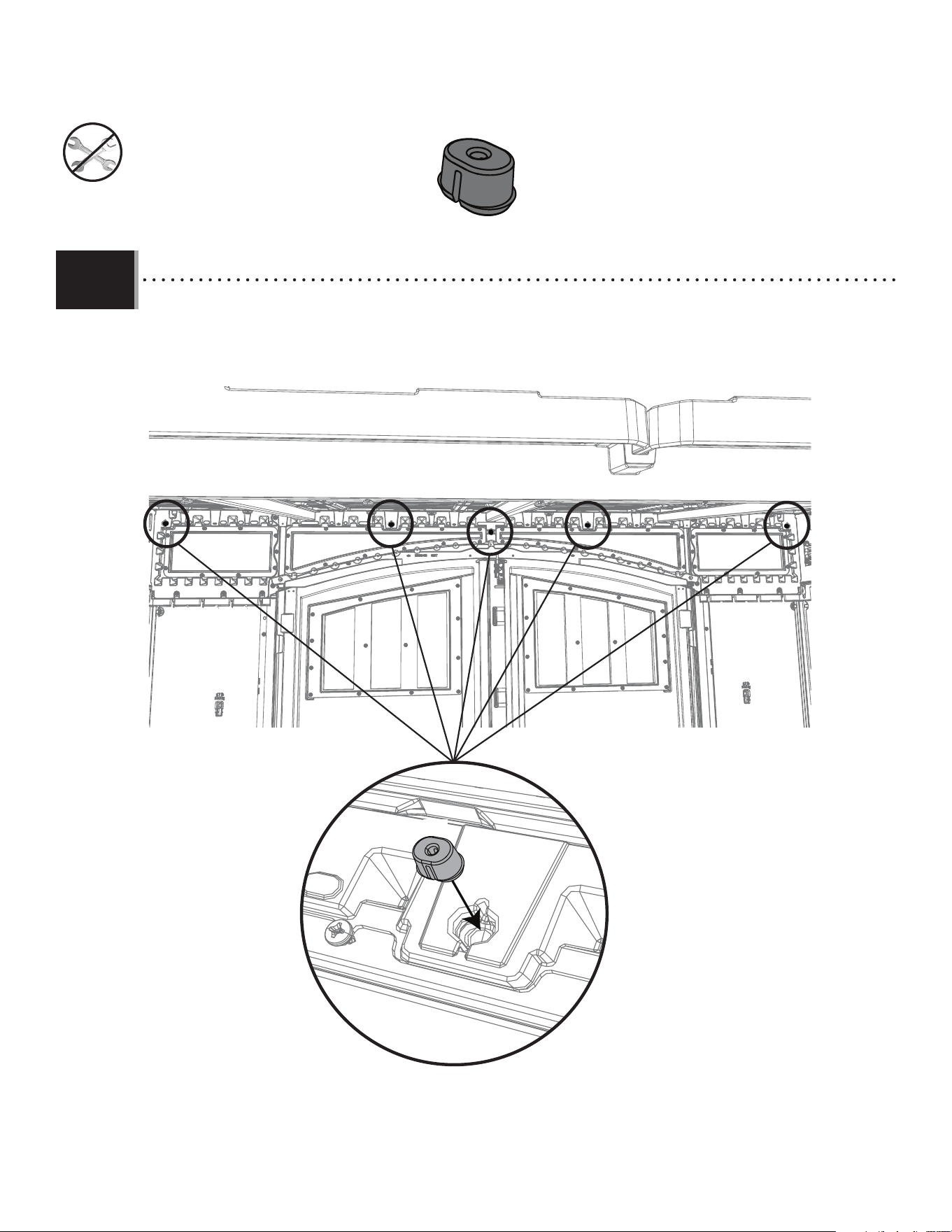
71
X SECTION 8 (CONTINUED) / SECTION 8 (SUITE) / SECCIÓN 8 (CONTINUACIÓN)
TOOLS AND HARDWARE REQUIRED / OUTILS ET QUINCAILLERIE REQUIS / INSTRUMENTAL Y HERRAJE REQUERIDOS
8.26
• Insert an anchor (FEX) into the transom at the fi ve (5) locations shown.
• Insérer un ancre (FEX) dans l’imposte aux cinq (5) endroites indiqués.
• Insertar un ancle (FEX) en el travesaño a las cinco (5) ubicaciones indicadas.
FEX (x5)
FEX
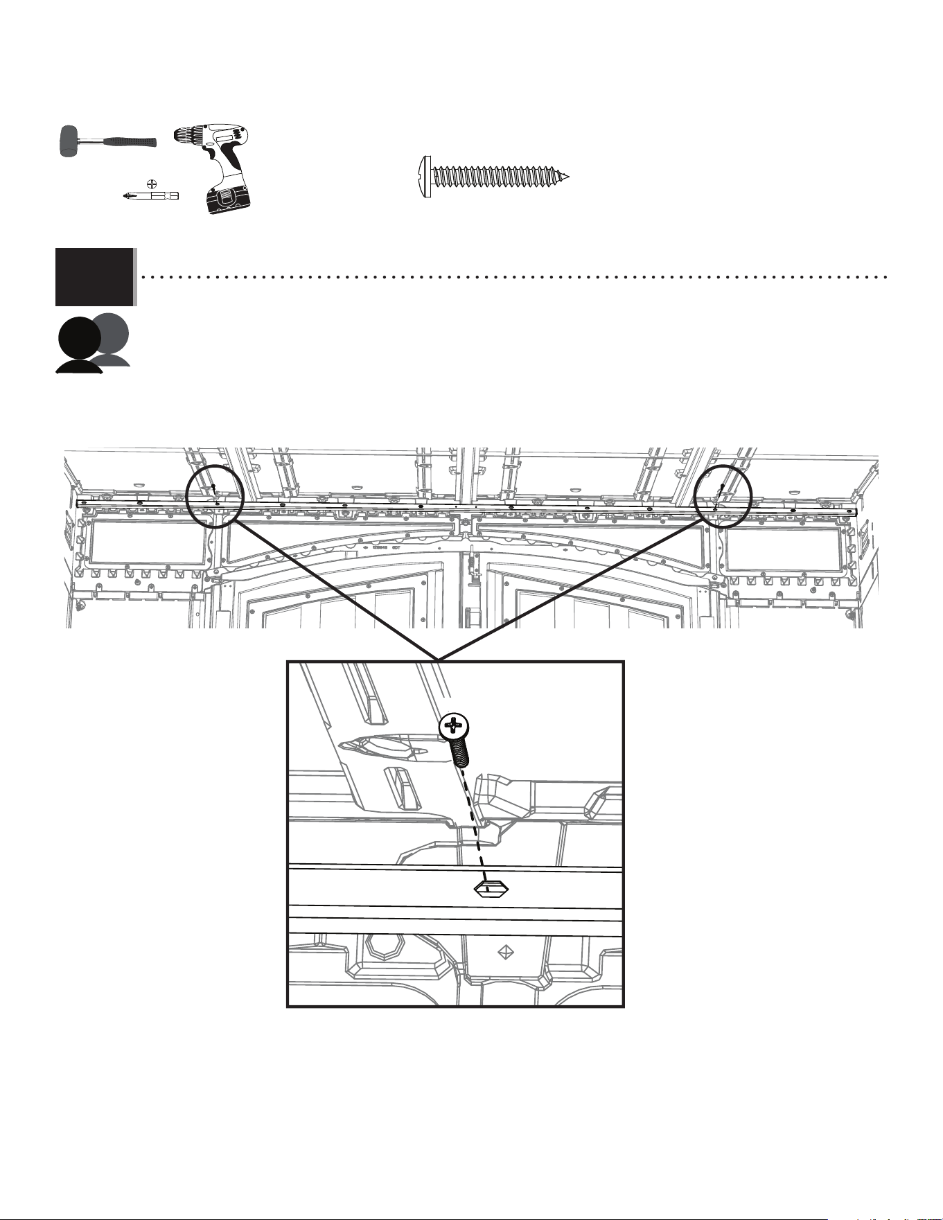
72
X SECTION 8 (CONTINUED) / SECTION 8 (SUITE) / SECCIÓN 8 (CONTINUACIÓN)
TOOLS AND HARDWARE REQUIRED / OUTILS ET QUINCAILLERIE REQUIS / INSTRUMENTAL Y HERRAJE REQUERIDOS
8.27
• Using two people, place the upper header (FVT) near the top of roof panels and attach the upper header in the locations
where the holes were drilled into the upper transom with the hardware indicated.
• À l’aide de deux personnes, placer le tube collecteur supérieur (FvT) près du côté supérieur des panneaux de toit et l’attacher là
où des trous ont été percés dans l’imposte supérieure avec la quincaillerie indiquée.
• Con dos personas, colocar el cabezal superior (FVT) cerca de la parte superior de los paneles del techo y fi jar el cabezal
superior en los lugares donde se perforaron los orifi cios en el travesaño superior con el herraje indicado.
ACB (x2)
ACB
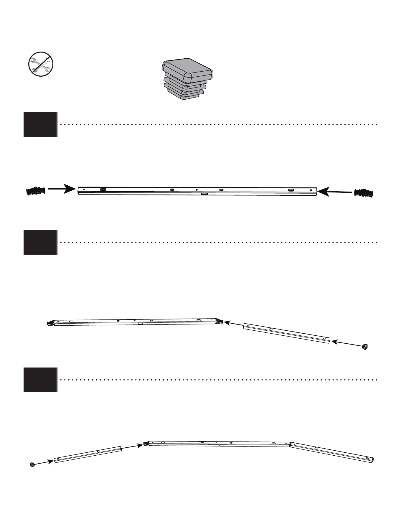
73
X SECTION 8 (CONTINUED) / SECTION 8 (SUITE) / SECCIÓN 8 (CONTINUACIÓN)
TOOLS AND HARDWARE REQUIRED / OUTILS ET QUINCAILLERIE REQUIS / INSTRUMENTAL Y HERRAJE REQUERIDOS
8.28
• Place the two-way square plugs (HDX) into both ends of the lower shed header (FVR). Use a mallet if necessary.
• Placer les bouchons carrés à deux voies (HDX) dans les deux extrémités du tube collecteur inférieur de la remise (FVR). Utiliser un maillet si
nécessaire.
• Colocar los tapones cuadrados de dos vías (HDX) en ambos extremos del cabezal inferior del cobertizo (FVR). Utilizar un mazo si es
necesario.
FVRHDX
HDX
8.29
• Place the angled header (FVS) onto the end of the two-way square plug and place the end plug (AHS) into the end of the angled
header.
• Placer le tube collecteur à angle (FVS) dans l’extrémité du bouchon carré à deux voies et placez le bouchon (AHS) dans l’extrémité
du tube collecteur à angle.
• Colocar el cabezal en ángulo (FVS) en el extremo del tapón cuadrado de dos vías y coloque el tapón de extremo (AHS) en el extremo
del cabezal en ángulo.
FVS
AHS
HDX
8.30
• Repeat step 8.29 to place the other angled header (FVS) onto the end of the lower header with the end plug (AHS).
• Répéter l’étape8.29 pour placer l’autre tube collecteur à angle (FVS) dans l’extrémité du tube collecteur inférieur à l’aide du
bouchon (AHS).
• Repetir el paso 8.29 para colocar el otro cabezal en ángulo (FVS) en el extremo del cabezal inferior con el tapón de extremo (AHS).
AHS
FVS
HDX
AHS (x2)
FVR
FVR
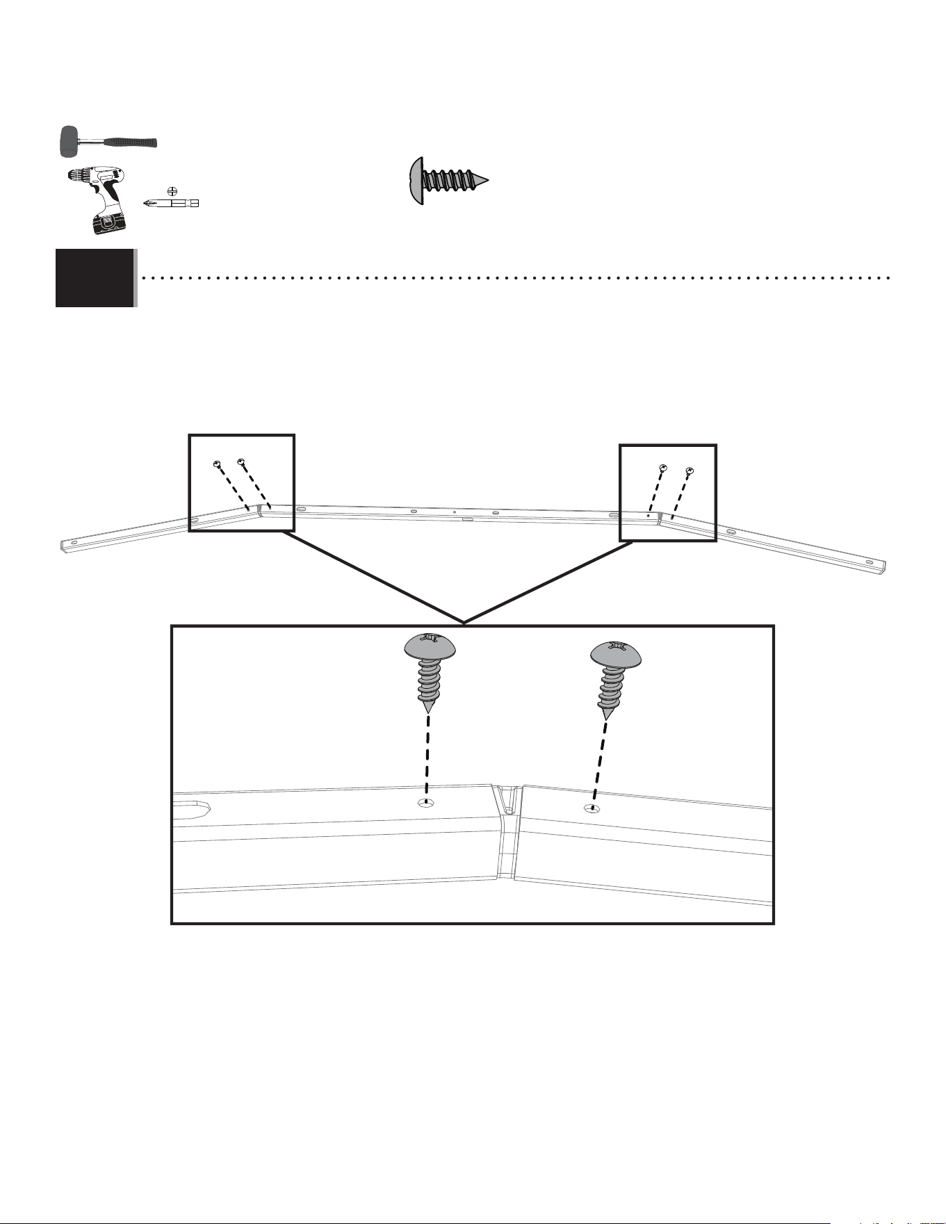
74
X SECTION 8 (CONTINUED) / SECTION 8 (SUITE) / SECCIÓN 8 (CONTINUACIÓN)
TOOLS AND HARDWARE REQUIRED / OUTILS ET QUINCAILLERIE REQUIS / INSTRUMENTAL Y HERRAJE REQUERIDOS
8.31
• Using a drill, place four (4) screws in the locations shown in the lower header. The screws will go through the two-
way square plug. Do not over-tighten the hardware.
• À l’aide d’une perceuse, placer quatre (4)vis aux endroits indiqués dans le tube collecteur inférieur. Les vis
traverseront le bouchon carré à deux voies. Ne pas serrer trop la quincaillerie!
• Con un taladro, colocar cuatro (4) tornillos en las ubicaciones que se muestran en el cabezal inferior. Los tornillos
pasarán por el tapón cuadrado de dos vías. No apretar demasiado el herraje.
IAU IAU
IAU
IAU
IAU (x4)
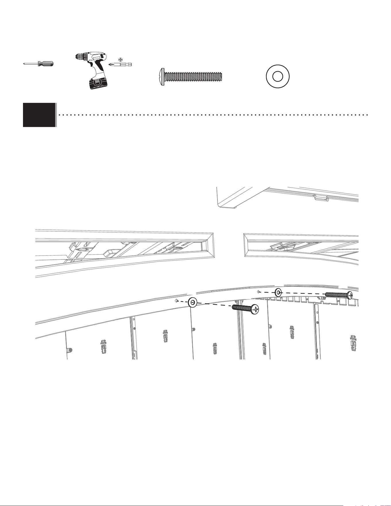
75
X SECTION 8 (CONTINUED) / SECTION 8 (SUITE) / SECCIÓN 8 (CONTINUACIÓN)
TOOLS AND HARDWARE REQUIRED / OUTILS ET QUINCAILLERIE REQUIS / INSTRUMENTAL Y HERRAJE REQUERIDOS
8.32
• Open the doors at the front of the shed. Screw in the hardware indicated into the bottom of the front of the transom
through the divots located there.
• Ouvrir les portes sur le devant de la remise. Visser la quincaillerie indiquée à travers des évidements qui sont situés dans
la partie inférieure du devant de l’imposte.
• Abrir las puertas en la parte delantera de la caseta. Atornillar el herraje indicado en la parte inferior del frente del
travesaño a través de los divots ubicados allí.
AEE
AEE
EYR
EYR
AEE (x2)
EYR (x2)
Or
Ou
O
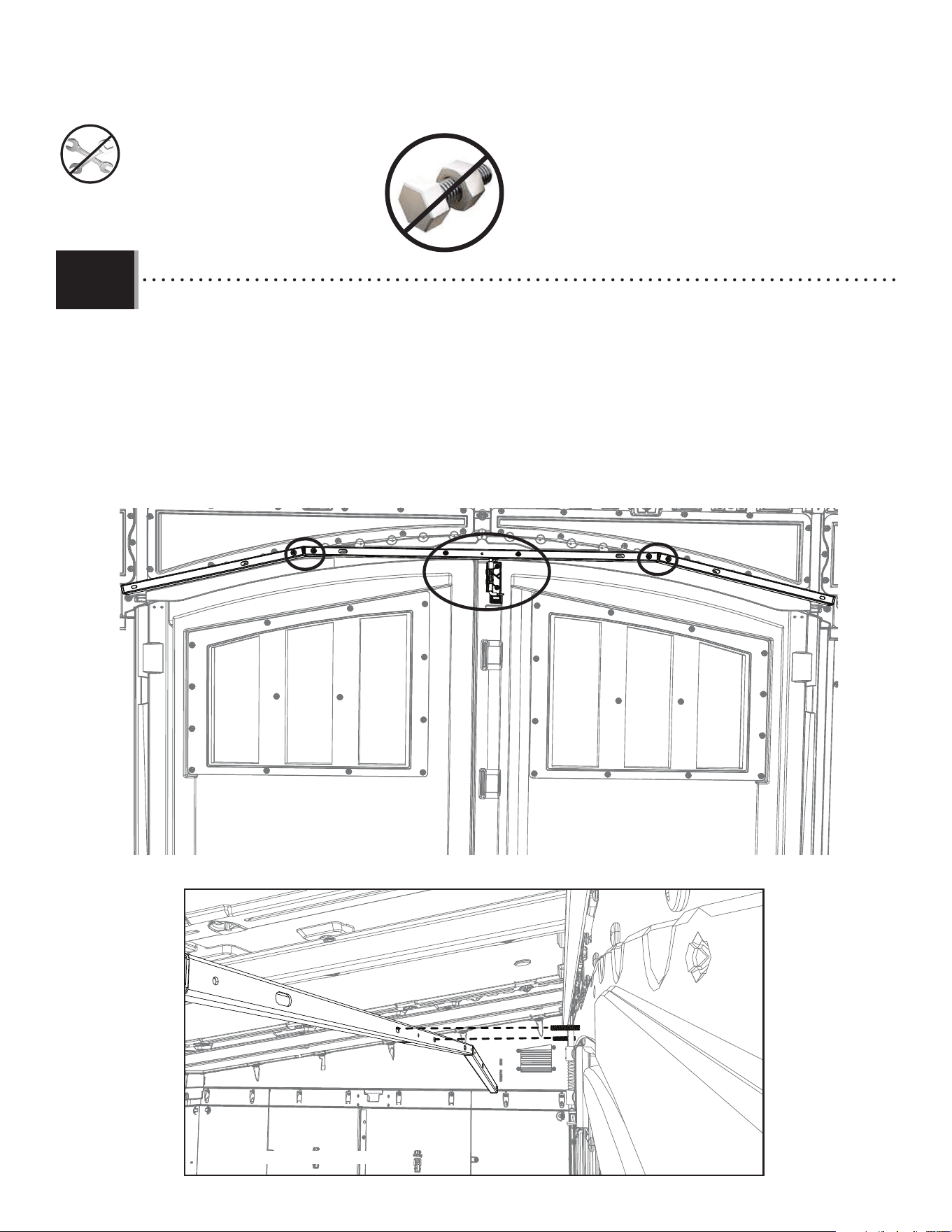
76
X SECTION 8 (CONTINUED) / SECTION 8 (SUITE) / SECCIÓN 8 (CONTINUACIÓN)
TOOLS AND HARDWARE REQUIRED / OUTILS ET QUINCAILLERIE REQUIS / INSTRUMENTAL Y HERRAJE REQUERIDOS
8.33
• Place the lower header onto the two (2) screws and washers that were placed in the last step. Be sure the screws in the
lower header are facing away from the transom. Have another person pull down on the spring lock on the door. The spring
lock will latch into the lower header at the bottom center of the header.
• Placer le tube collecteur inférieur sur les deux (2)vis et espaceurs que vous y avez placé dans la dernière étape.
Vérifi ez que les vis dans le tube collecteur inférieur sont dirigées à l’opposée de l’imposte. Demandez à une autre personne de le
tirer vers le bas sur le verrou à ressort sur la porte. Le verrou à ressort s’enclenchera dans le tube collecteur inférieur
situé en bas au centre du tube.
• Colocar el cabezal inferior en los dos (2) tornillos y arandelas que se colocaron en el último paso. Asegurarse de que los
tornillos del cabezal inferior estén orientados en dirección opuesta al travesaño. Pedirle a otra persona que tire hacia abajo del
seguro de resorte de la puerta. El seguro de resorte se enganchará en el cabezal inferior en la parte inferior central
del cabezal.
Front view / Vue de l’avant / Vista frontal
Rear view / Vue de l’arrière / Vista trasera
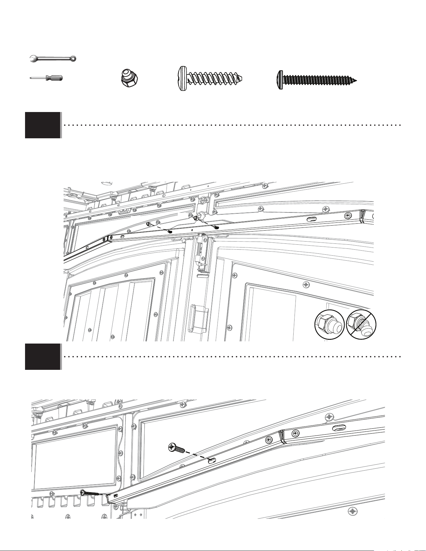
77
X SECTION 8 (CONTINUED) / SECTION 8 (SUITE) / SECCIÓN 8 (CONTINUACIÓN)
TOOLS AND HARDWARE REQUIRED / OUTILS ET QUINCAILLERIE REQUIS / INSTRUMENTAL Y HERRAJE REQUERIDOS
8.34
• Attach the lower header to the transom by placing two (2) cap nuts (ADK) over the two (2) screws that protrude through
the lower header. Do not overtighten the cap nut.
• Attacher le tube collecteur inférieur sur l’imposte en plaçant deux (2)écrous borgnes (ADK) sur les deux (2)vis qui font
saillie à travers le tube collecteur inférieur. Ne pas serrer trop l’écrou borgne.
• Fijar el cabezal inferior al travesaño colocando dos (2) tuercas ciegas (ADK) sobre los dos (2) tornillos que sobresalen del
cabezal inferior. No apretar demasiado la tuerca ciega.
ADK
ADK
ADK (x2)
3/8 in/po (≈10 mm)
8.35
• Attach the left side of the lower header to the transom with the hardware indicated.
• Fixer le côté gauche du tube collecteur inférieur à l’imposte avec la quincaillerie indiquée.
• Con el herraje indicado, fi jar el lado izquierdo del cabezal inferior al travesaño.
ADV
HDZ
ADV (x1) HDZ (x1)
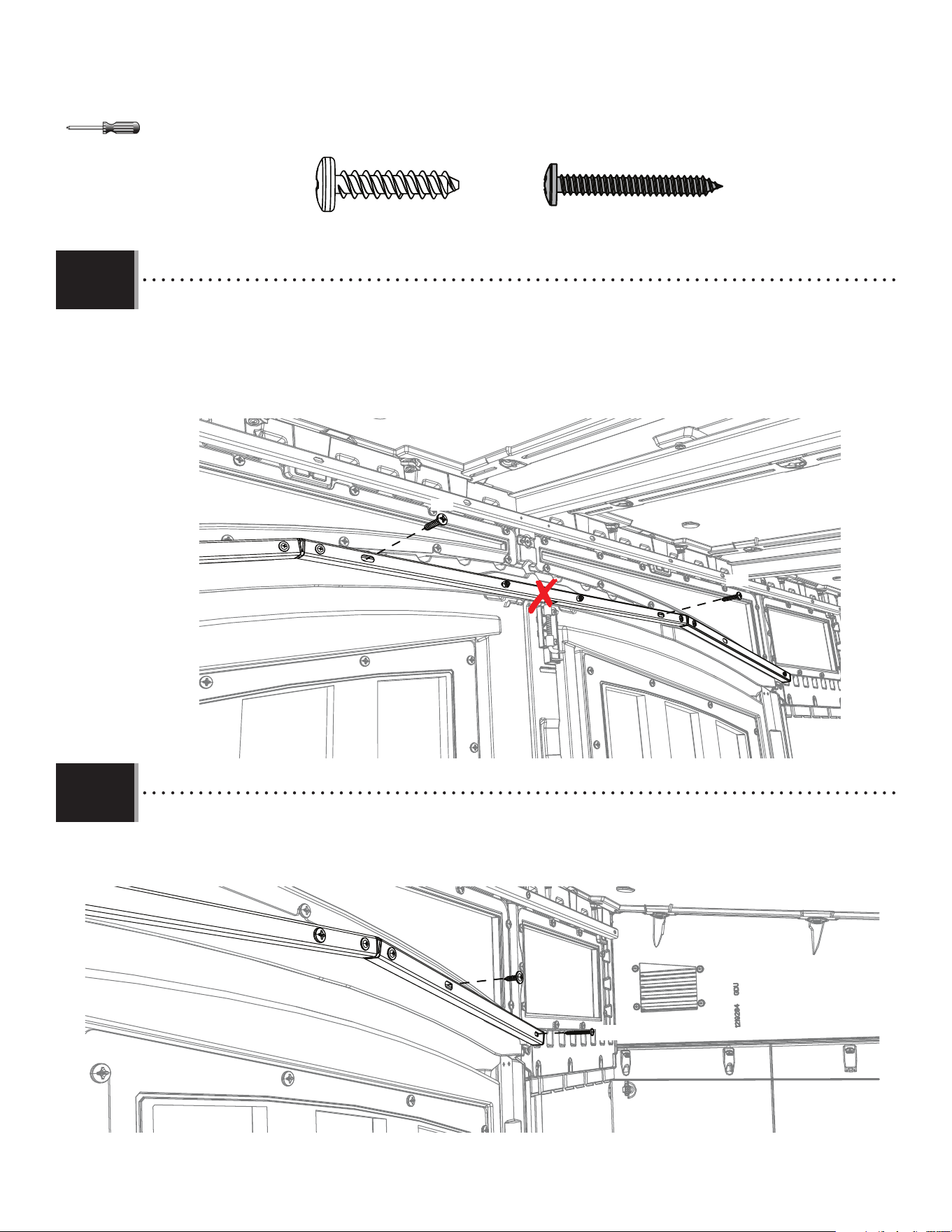
78
X SECTION 8 (CONTINUED) / SECTION 8 (SUITE) / SECCIÓN 8 (CONTINUACIÓN)
TOOLS AND HARDWARE REQUIRED / OUTILS ET QUINCAILLERIE REQUIS / INSTRUMENTAL Y HERRAJE REQUERIDOS
8.36
• Secure the middle section of the lower header using the hardware indicated. Do not place any hardware into the
center hole at this time.
• Fixer la partie centrale du tube collecteur inférieur avec la quincaillerie indiquée. Ne placer pas de quincaillerie dans
le trou central en ce moment.
• Asegurar la sección central del cabezal inferior usando el herraje indicado. No colocar ningún herraje en el orifi cio
central en este momento.
ADV (x3)
ADV
ADV
8.37
• Secure the right section of the lower header using the hardware indicated.
• Fixer la partie droite du tube collecteur inférieur avec la quincaillerie indiquée.
• Asegurar la sección derecha del cabezal inferior usando el herraje indicado.
ADV
HDZ
HDZ (x1)
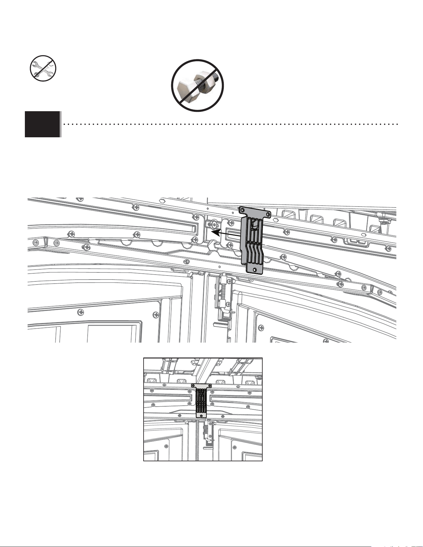
79
X SECTION 8 (CONTINUED) / SECTION 8 (SUITE) / SECCIÓN 8 (CONTINUACIÓN)
TOOLS AND HARDWARE REQUIRED / OUTILS ET QUINCAILLERIE REQUIS / INSTRUMENTAL Y HERRAJE REQUERIDOS
8.38
• Place the vertical brace (FVU) in between the lower and upper header. It will sit in the middle of the headers.
• Placer le support de fi xation vertical (FVU) entre les tubes collecteurs inférieur et supérieur. Il sera au centre des tubes
collecteurs.
• Colocar la riostra vertical (FVU) entre los cabezales superior e inferior. Se sentará en el medio de los cabezales.
FVU
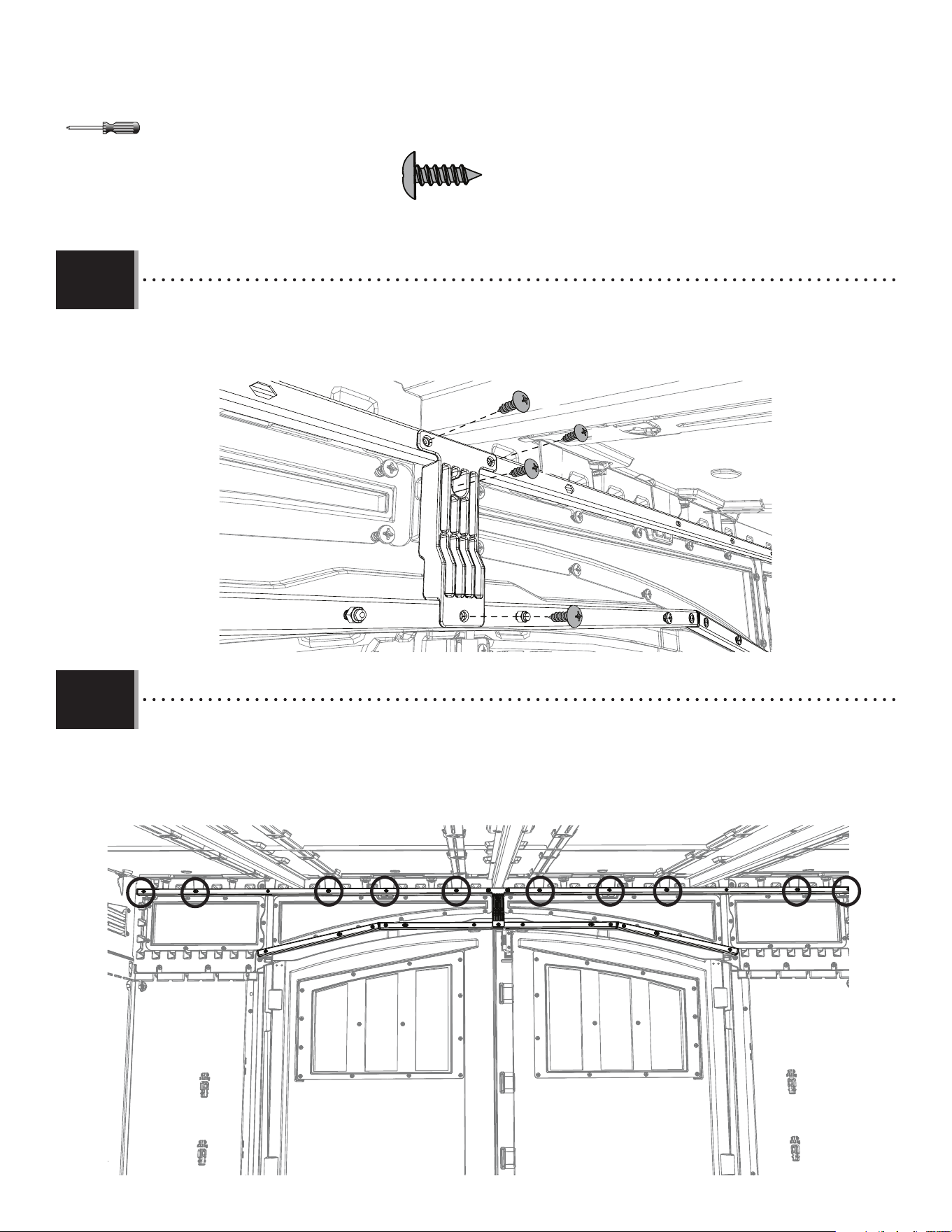
80
X SECTION 8 (CONTINUED) / SECTION 8 (SUITE) / SECCIÓN 8 (CONTINUACIÓN)
TOOLS AND HARDWARE REQUIRED / OUTILS ET QUINCAILLERIE REQUIS / INSTRUMENTAL Y HERRAJE REQUERIDOS
8.39
• Attach the vertical brace (FVU) against the upper and lower headers using the hardware indicated.
• Fixer le support de fi xation vertical (FVU) contre les tubes collecteurs supérieur et inférieur avec le matériel indiqué.
• Colocar la riostra vertical (FVU) contra los cabezales superior e inferior usando el herraje indicado.
IAU
IAU
IAU
IAU
IAU (x4)
8.40
• This is the hardware placement for the upper header (FVT). The next two (2) steps will show the types of hardware that will
be used to install the upper header.
• Ceci est le placement de la quincaillerie pour le tube collecteur supérieur (FVT). Les deux (2) prochaines étapes vous
montreront le type de quincaillerie à utiliser pour l’installation du tube collecteur supérieur.
• Esta es la colocación del herraje para el cabezal superior (FVT). Los siguientes dos (2) pasos mostrarán los tipos de herraje
que se utilizarán para instalar el cabezal superior.
FVT
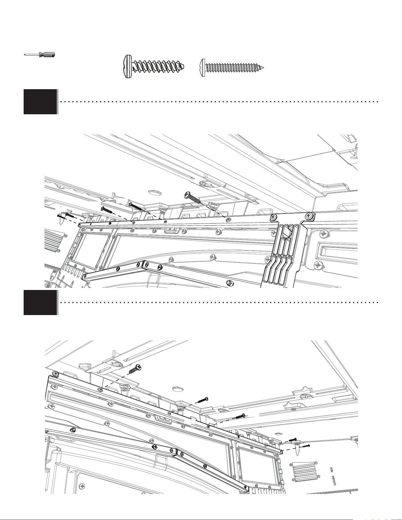
81
X SECTION 8 (CONTINUED) / SECTION 8 (SUITE) / SECCIÓN 8 (CONTINUACIÓN)
TOOLS AND HARDWARE REQUIRED / OUTILS ET QUINCAILLERIE REQUIS / INSTRUMENTAL Y HERRAJE REQUERIDOS
8.42
• Using two (2) adults, attach the upper header (FVT) on the right side using the hardware indicated.
• À l’aide de deux (2)adultes, fi xer le tube collecteur supérieur (FVT) du côté droit à l’aide de la quincaillerie indiquée.
• Con la ayuda de dos (2) adultos, conectar el cabezal superior (FVT) en el lado derecho usando el herraje indicado.
ACB
ACB
ADV
ADV
ADV
ADV (x6)
ACB (x4)
8.41
• Using two (2) adults, attach the upper header (FVT) on the left side using the hardware indicated.
• À l’aide de deux (2)adultes, fi xer le tube collecteur supérieur (FVT) du côté gauche à l’aide de la quincaillerie indiquée.
• Con la ayuda de dos (2) adultos, conectar el cabezal superior (FVT) en el lado izquierdo usando el herraje indicado.
ACB
ACB
ADV
ADV
ADV
FVT
FVT
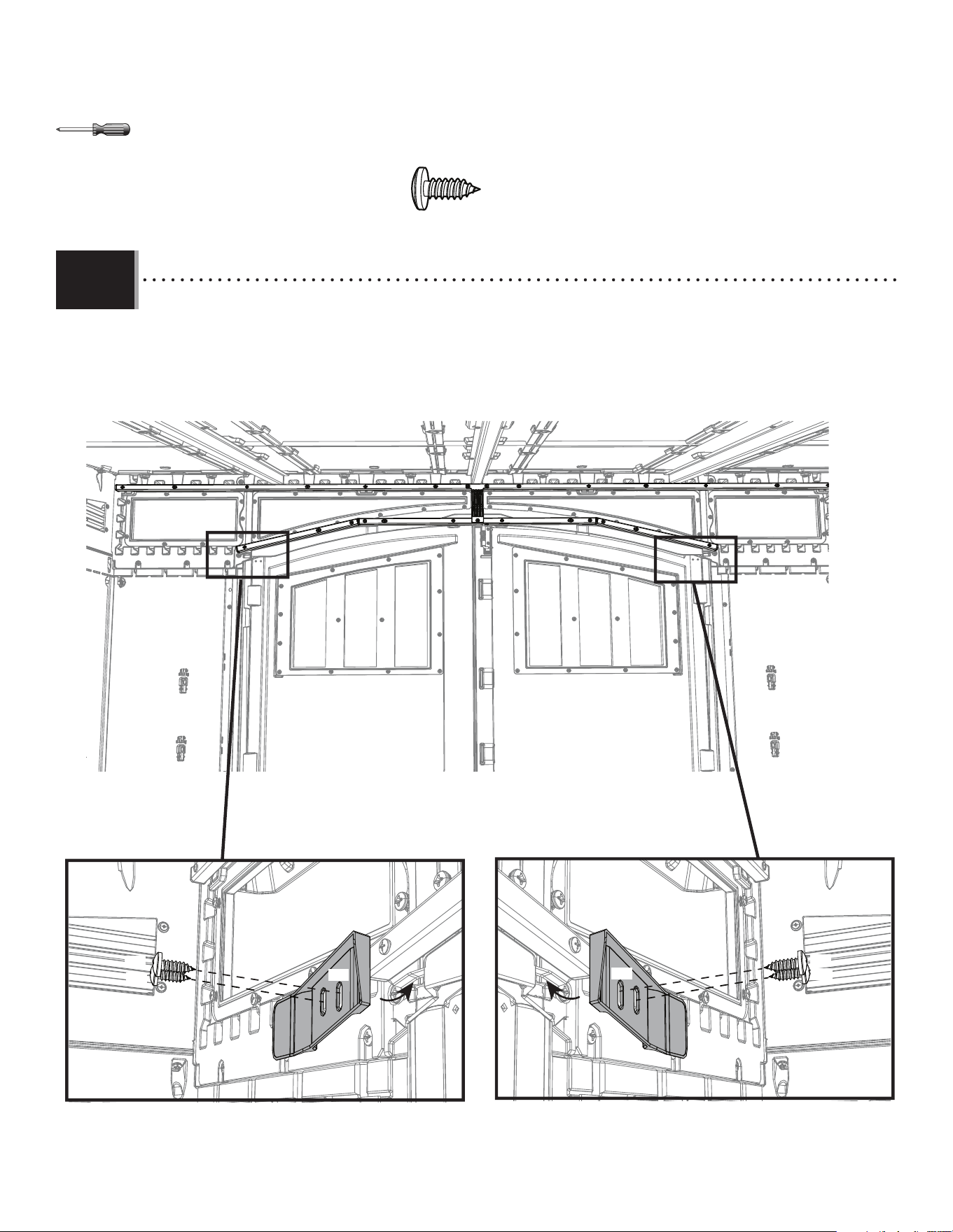
82
X SECTION 8 (CONTINUED) / SECTION 8 (SUITE) / SECCIÓN 8 (CONTINUACIÓN)
TOOLS AND HARDWARE REQUIRED / OUTILS ET QUINCAILLERIE REQUIS / INSTRUMENTAL Y HERRAJE REQUERIDOS
8.43
• Install the left (AIC) and right (AIM) gap fl aps using the hardware indicated. The fl aps slide under the transom and serve to
block out light.
• Installer les rabats des espaces gauche (AIC) et droit (AIM) à l’aide de la quincaillerie indiquée. Les rabats se glissent sous l’imposte
et servent à masquer la lumière.
• Instalar las solapas de separación izquierda (AIC) y derecha (AIM) usando el herraje indicado. Las solapas se deslizan debajo del
travesaño y sirven para bloquear la luz.
AIM
AIC
ADX
ADX
ADX
ADX
ADX (x4)
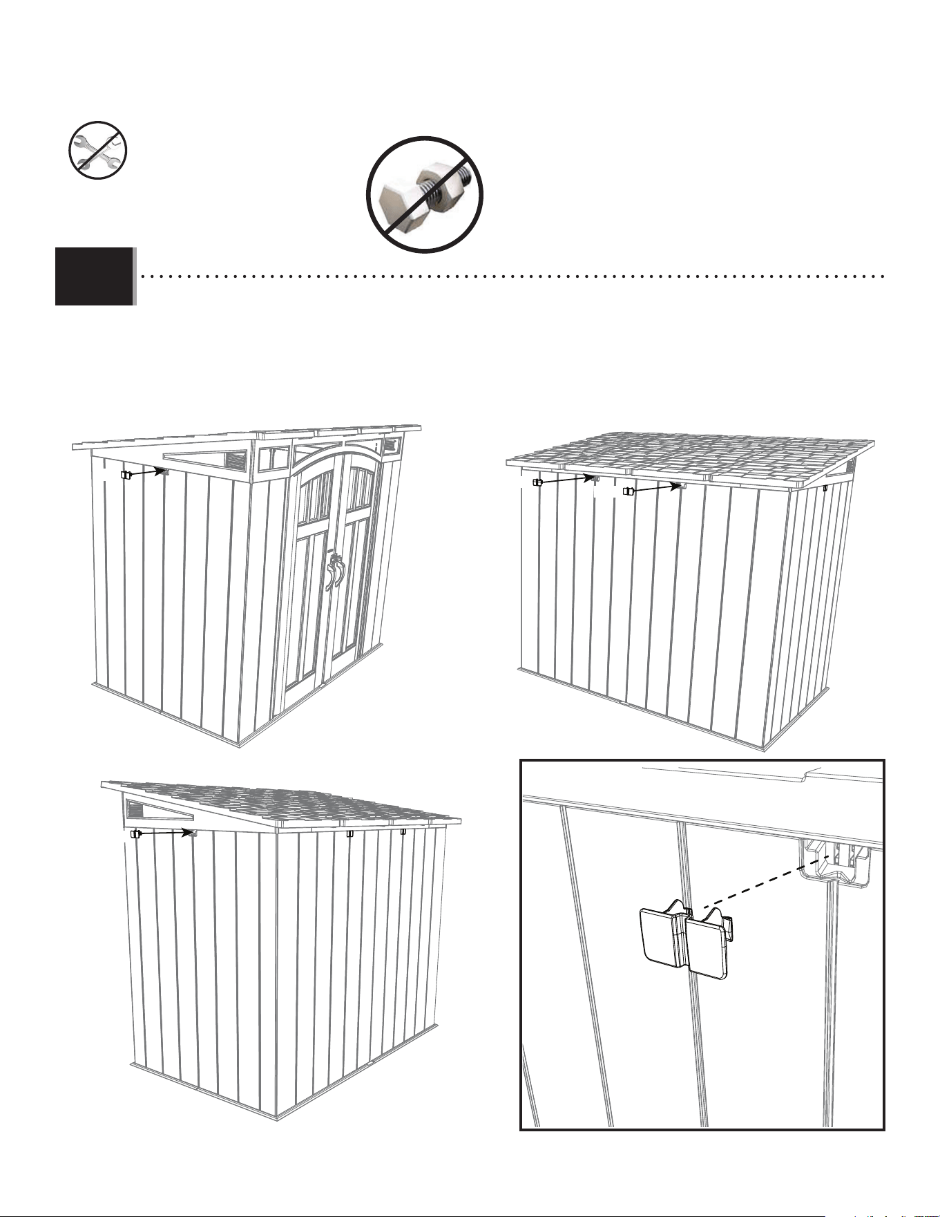
83
X SECTION 8 (CONTINUED) / SECTION 8 (SUITE) / SECCIÓN 8 (CONTINUACIÓN)
TOOLS AND HARDWARE REQUIRED / OUTILS ET QUINCAILLERIE REQUIS / INSTRUMENTAL Y HERRAJE REQUERIDOS
8.44
• Install four (4) truss slot covers (HDW) on both sides and the rear of the shed.
• Installer quatre (4)couvercles des rainures des fermes (HDW) sur les deux côtés et l’arrière de la remise.
• Instalar cuatro (4) cubiertas de ranuras de armadura (HDW) a ambos lados y en la parte trasera de la caseta.
HDW
HDW
HDW
HDW
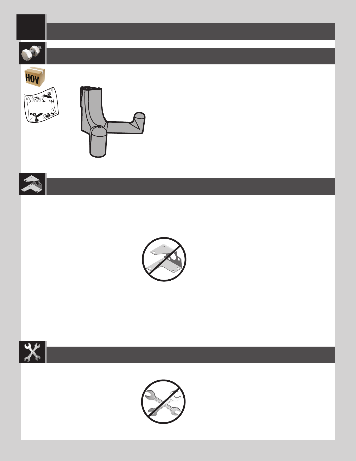
84
ACCESSORIES REQUIRED / ACCESSOIRES REQUIS / ACCESORIOS REQUERIDOS
PARTS REQUIRED / PIÈCES REQUISES / PIEZAS REQUERIDAS
EDH
EDL (x6)
WALL HOOK INSTALLATION / INSTALLATION DES CROCHETS MURAUX / INSTALACIÓN DE LOS GANCHOS MURALES
9
TOOLS REQUIRED / OUTILS REQUIS / INSTRUMENTAL REQUERIDO
(Not included—unless otherwise indicated*) / (Non inclus — sauf indication contraire*) / (No incluido, salvo indicación contraria*)
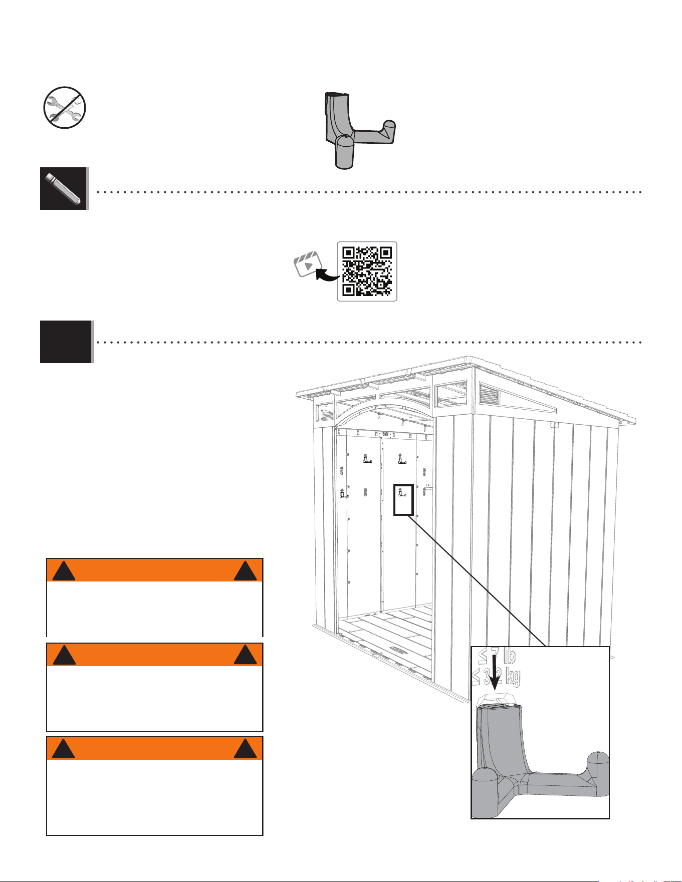
85
TOOLS AND ACCESSORIES REQUIRED / OUTILS ET QUINCAILLERIE REQUIS / INSTRUMENTAL Y ACCESORIOS REQUERIDOS
X SECTION 9 (CONTINUED) / SECTION 9 (SUITE) / SECCIÓN 9 (CONTINUACIÓN)
• Insert the six (6) wall hooks (EDL) into
any of the notches in the wall panels
(any wall of the shed). Then push
downward to lock them in place.
• Insérer les six (6) crochets muraux (EDL) dans
les fentes des panneaux muraux (peu
importe le mur de la remise). Appuyer
vers le bas pour les fi xer en place.
• Insertar los seis (6) ganchos murales (EDL)
en cualquiera de las muescas en los
paneles murales (de cualquier muro
de la caseta). Después, presionar
hacia abajo para fi jarlos en su lugar.
9.1
EDL (x6)
! !
WARNING
The total weight on a wall hook should not exceed
7 lb (3.2 kg) nor more than 30 lb (14 kg) on a wall
panel. Failure to follow this warning could result in
propety damage and/or personal injury.
ADVERTENCIA
El peso total en un gancho mural no debe
exceder de 7 lb (3.2 kg) ni más de 30 lb
(14 kg) en un panel mural. El no seguir esta
advertencia puede resultar en daños a la
propiedad y/o en lesiones graves personales.
!
!
AVERTISSEMENT
Le poids total sur un crochet mural ne devrait
pas excéder ≈3.2 kg (7 lb) ou plus de ≈14 kg (30
lb) sur un panneau mural. Le non-respect de cet
avertissement peut entraîner des dommages à la
propriété et/ou des blessures graves.
!
!
EDL
EDL
EDL
EDL
EDL
http://go.lifetime.com/compactmodernshed-section9
LIFETIME
®
• In case of troubles with this section, scan the QR code below to view a video on its assembly.
• En cas d’avoir des problèmes avec cette section, scanner le code QR en dessous pour voir un vidéo de l’assemblage.
• En caso de tener problemas con esta sección, escanear el código QR debajo para ver un video del ensamblaje.
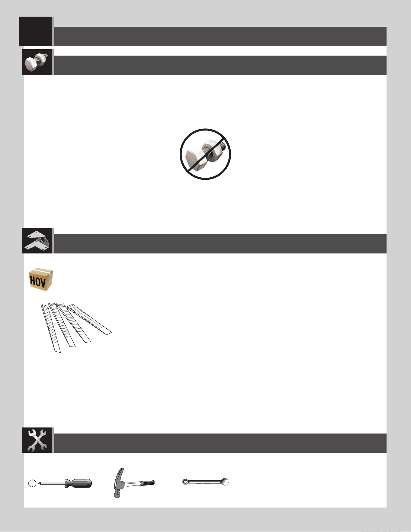
86
PARTS REQUIRED / PIÈCES REQUISES / PIEZAS REQUERIDAS
HARDWARE REQUIRED / QUINCAILLERIE REQUISE / HERRAJE REQUERIDO
AIX (x4)
Plastic parts / Pièces en plastique / Piezas de plástico
DOOR ALIGNMENT / ALIGNEMENT DES PORTES / ALINEACIÓN DE LAS PUERTAS
10
TOOLS REQUIRED / OUTILS REQUIS / INSTRUMENTAL REQUERIDO
(Not included—unless otherwise indicated*) / (Non inclus — sauf indication contraire*) / (No incluido, salvo indicación contraria*)
7/16" (≈11 mm)
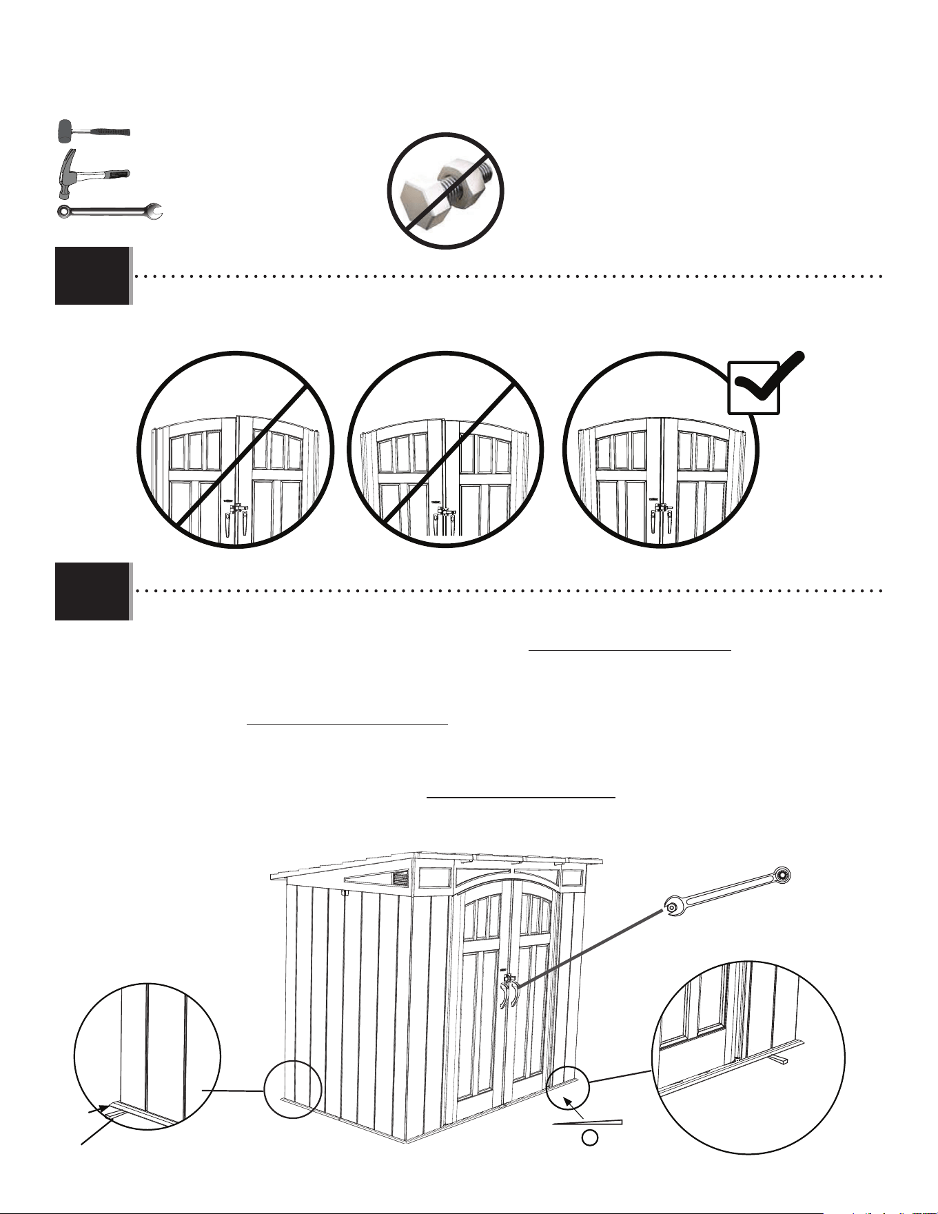
87
X SECTION 10 (CONTINUED) / SECTION 10 (SUITE) / SECCIÓN 10 (CONTINUACIÓN)
TOOLS AND HARDWARE REQUIRED / OUTILS ET QUINCAILLERIE REQUIS / INSTRUMENTAL Y HERRAJE REQUERIDOS
AIX
• If the doors are not level, follow the steps below to even them out.
• Si les portes ne sont pas niveaux l’une avec l’autre, suivre les étapes dans cette page pour les niveler.
• Si las puertas no estén niveladas, seguir los pasos en esta página para nivelarlas.
10.1
10.2
AIX
AIX
1
• If the right door scrapes the fl oor or is lower than the left door, insert a shim (AIX) under the fl oor directly under the
bottom corner of the right door and/or the left rear corner of the shed. If necessary, repeat for the left door until
both doors are level and do not scrape. Break o any excess shim. Tighten the hardware from steps 2.3.
• Si la porte doite frotte en se ferment ou est plus bas que la porte gauche, insérer une cale (AIX) sous le plancher
directement sous le coin droit inférieur de la porte droite et/ou l’encoignure arrière gauche de l’abri. Si besoin,
répéter cette étape pour la porte gauche jusqu’à ce que les deux portes soient nivelles et ne frottent pas. Détacher
de l’excès des cales. Serrer la quincaillerie des étapes 2.3.
• Si la puerta derecha se roza con el piso o está más bajo que la izquierda, insertar una cuña (AIX) debajo el piso
directamente debajo la esquina inferior derecha de la puerta derecha y/o la esquina izquierda trasera de la
caseta. Si es necesario, repetir este paso para la puerta izquierda o hasta que las dos puertas estén niveladas y
no se rocen. Quebrantar cualquier exceso de las cuñas. Apretar el herraje de los pasos 2.3.
7/16" (≈11 mm)
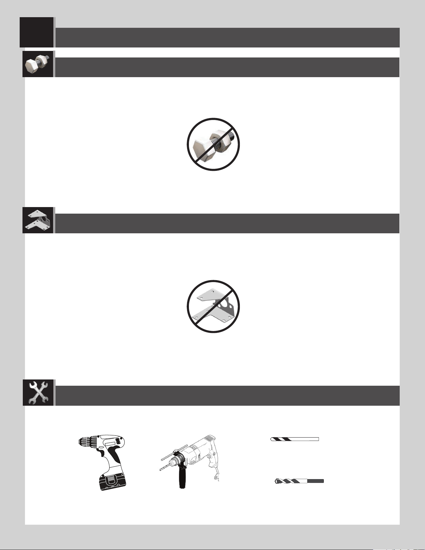
88
PARTS REQUIRED / PIÈCES REQUISES / PIEZAS REQUERIDAS
HARDWARE REQUIRED / QUINCAILLERIE REQUISE / HERRAJE REQUERIDO
5/16 in/po (≈8 mm) Wood Drill Bit
Foret à boit de 8 mm
Broca para madera de 8 mm
5/16 in/po (≈8 mm) Masonry Drill Bit
Foret à maçonnerie de 8 mm
Broca para albañilería de 8 mm
SHED ANCHORING / ANCRAGE DE L’ABRI / ANCLAJE DE LA CASETA
11
TOOLS REQUIRED / OUTILS REQUIS / INSTRUMENTAL REQUERIDO
(Not included—unless otherwise indicated*) / (Non inclus — sauf indication contraire*) / (No incluido, salvo indicación contraria*)
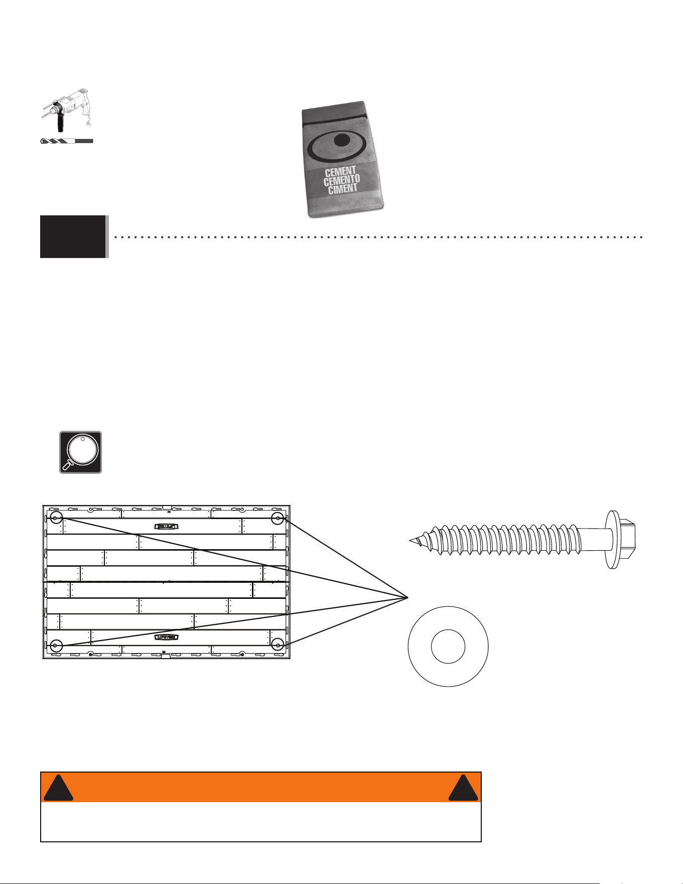
89
X SECTION 11 (CONTINUED) / SECTION 11 (SUITE) / SECCIÓN 11 (CONTINUACIÓN)
(x4)
(x4)
5/16 in/po
(≈8 mm)
(Not included) (Pas incluses) (No incluidas)
(Not included) (Pas incluses) (No incluidas)
• If you plan on anchoring your shed to a concrete platform, you must purchase the correct anchoring
hardware. We recommend using a hammer drill, 5/16" (≈8 mm) masonry bit, four (4) 3/8" x 2" (≈1 cm x 5 cm)
concrete screws and four (4) 3/8" x 1" (≈1 cm x 2,5 cm) fender washers.
• Pour ancrer l’abri sur une plateforme de beton, il faut procurer la quincaillerie d’ancrage appropriée. Nous
recommandons l’utilisation d’un marteau perforateur, d’un foret de maçonnerie de 5/16 po (≈8 mm), quatre
(4) vis de scellement de 3/8 po x 2 po (≈1 cm x 5 cm) et quatre (4) rondelles de protection de 3/8 po x 1 po (1
cm x 2,5 cm).
• Para anclar la caseta a una plataforma hecho de concreto, es necesario comprar el herraje de anclaje
correcto. Recomendamos el uso de un rotomartillo, una broca para albañilería de ≈8 mm (5/16 in), cuatro (4)
tornillos de anclaje para concreto de ≈1 cm x 5 cm (3/8 in x 2 in) y cuatro (4) rondanas de protección de ≈1
cm x 2,5 cm (3/8 in x 1 in).
11.1a
• Do not exceed a 3/8" (≈10 mm) diameter screw. Refer to your local hardware store for this hardware.
• Ne pas excéder une vis de diamètre de 3/8 po (≈10 mm). Consulter votre quincaillerie locale pour cette exigence.
• No usar tornillos que exceden un diámetro de 10 mm (≈3/8 in). Consultar con su ferretería local para obtener este herraje.
FOR A CONCRETE PLATFORM / POUR UNE PLATE-FORME EN BÉTON / PARA UNA PLATAFORMA DE CONCRETO
• Failure to anchor the shed may result in property damage and/or personal injury.
• Si vous n’ancrez pas votre abri, des dommages à la propriété et/ou des blessures peuvent en résulter.
• No anclar la caseta puede resultar en daños a la propiedad y/o en lesiones personales.
WARNING / AVERTISSEMENT / ADVERTENCIA
! !
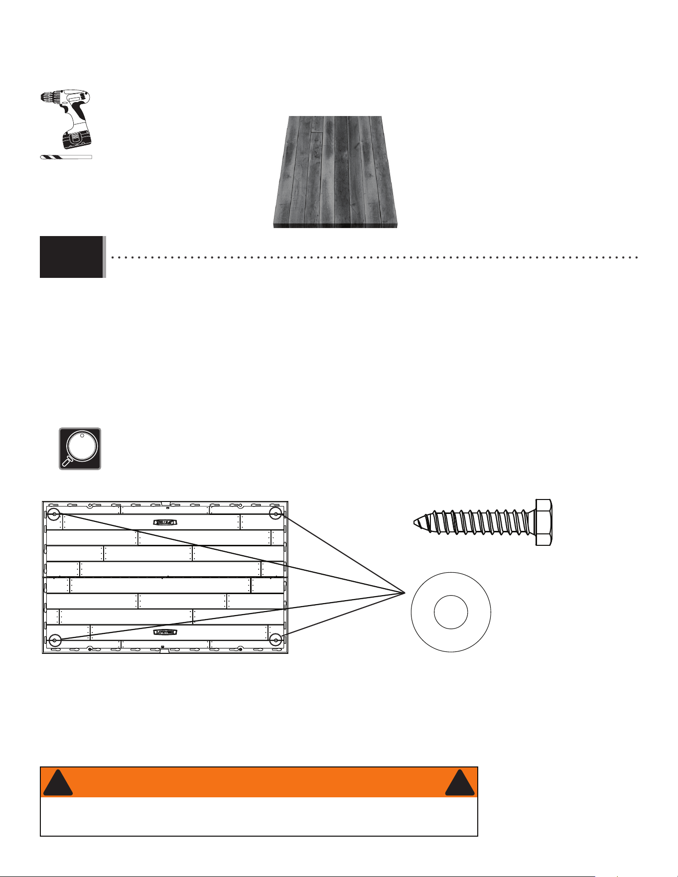
90
X SECTION 11 (CONTINUED) / SECTION 11 (SUITE) / SECCIÓN 11 (CONTINUACIÓN)
• If you plan on anchoring your shed to a wood platform, you must purchase the correct anchoring hardware. We
recommend using a drill, 5/16" (≈8 mm) drill bit, four (4) 3/8" x 1 1/2" (≈1 cm x 4 cm) lag screws and four (4)
3/8" x 1" (≈1 cm x 2,5 cm) fender washers.
• Pour ancrer l’abri à une plate-forme en bois, il faut acheter la quincaillerie d’ancrage correcte. Nous
recommandons l’utilisation d’une perceuse, d’une mèche de 5/16 po (≈8 mm), quatre (4) tirefonds de 3/8 po x 1
1/2 po (≈1 cm x 4 cm) et quatre (4) rondelles de protection de 3/8 po x 1 po (≈1 cm x 2,5 cm).
• Para anclar su caseta a una plataforma hecho de madera, es necesario comprar el herraje de anclaje correcto.
Recomendamos usar un taladro eléctrico, una broca de ≈8 mm (5/16 in), cuatro (4) tornillos para compresión de
≈1 cm x 4 cm (3/8 in x 1 1/2 in), y cuatro (4) rondanas de protección de ≈1 cm x 2,5 cm (3/8 in x 1 in).
(x4)
(x4)
(Not included) (Pas incluses) (No incluidas)
(Not included) (Pas incluses) (No incluidas)
11.1b
5/16 in/po
(≈8 mm)
• Do not exceed a 3/8" (≈1 cm) diameter screw. Refer to your local hardware store for this hardware.
• Ne pas excéder une vis de diamètre de 3/8 po (≈1 cm). Consulter votre quincaillerie locale pour cette exigence.
• No usar tornillos que exceden un diámetro de ≈10 cm (≈3/8 in). Consultar con su ferretería local para obtener este herraje.
FOR A WOOD PLATFORM / POUR UNE PLATE-FORME EN BOIS / PARA UNA PLATAFORMA DE MADERA
• Failure to anchor the shed may result in property damage and/or personal injury.
• Si vous n’ancrez pas votre abri, des dommages à la propriété et/ou des blessures peuvent en résulter.
• No anclar la caseta puede resultar en daños a la propiedad y/o en lesiones personales.
WARNING / AVERTISSEMENT / ADVERTENCIA
! !

91
NOTES / REMARQUES / NOTAS
LIFETIME
®

92
NOTES / REMARQUES / NOTAS
LIFETIME
®

93
NOTES / REMARQUES / NOTAS
LIFETIME
®

94
Congratulations on your Lifetime
®
product purchase. By following the instructions below, your new Lifetime product should provide you with years of service and enjoyment.
The polyethylene panels are stain and solvent resistant. Most stains can be removed using a mild soap and a soft-bristled
brush. Abrasive cleaning materials may scratch the plastic and are not recommended. Repair scratches or rust spots on the
metal by sanding the a ected area lightly; using a rust preventative spray primer; and fi nally, spraying with a high-gloss spray
enamel paint. Avoid placing a direct heat source on or near surfaces unless using a heat barrier.
Nous vous félicitons d’avoir acheté ce produit Lifetime
®
. En suivant les instructions ci-dessous, votre nouveau produit Lifetime devrait vous fournir des années de service et de plaisir.
Les murs et les étagères en polyéthylène sont résistants aux taches et solvants de nettoyage. Pour les nettoyer, se servir
d’un savon doux et d’une brosse douce. Les produits abrasifs de nettoyage risquent d’égratigner le plastique et ne sont pas
recommandés. Pour réparer les égratignures ou taches de rouille sur le métal, frotter légèrement l’endroit a ecté au papier de
verre, puis passer une couche de produit vaporisant préventif, et, enfi n, vaporiser une peinture émail ultrabrillante. Éviter de
placer une source de chaleur directe sur ou près des surfaces, ou les protéger à l’aide d’une protection contre la chaleur.
CLEANING & CARE
NETTOYAGE ET ENTRETIEN
Felicidades por la compra de su producto Lifetime
®
. Al seguir las siguientes instrucciones, su nuevo producto Lifetime le brindará años de servicio y satisfacción.
Los paneles de polietileno son resistentes a las manchas y solventes. La mayoría de las manchas, pueden removerse
usando un jabón suave y un cepillo de cerdas suaves. Los materiales abrasivos para limpieza pueden rayar el plástico y no
se recomiendan. Reparar rayones o manchas de óxido en el metal, lijando suavemente la parte afectada; usando un aerosol
preventivo de óxido y fi nalmente, rociando con una pintura de esmalte brillante. Evitar poner una fuente de calor directa en o
cerca de las superfi cies sin usar una barrera de calor.
LIMPIEZA Y CUIDADO

95
LIFETIME’S PROMISE TO YOU:
We invite you to read our privacy policy at www.lifetime.com
REGISTER today!
At Lifetime
®
, we are committed to providing innovative and quality products. While registering, you will have the opportunity to give us your feedback. Your input is valuable to us.
• You can also opt in to receive new product notifi cations or promotions.
• In the unlikely event of a product recall or safety modifi cation, your registration provides the information we need to notify you directly.
• Registration is fast, easy, and completely voluntary.
Maintaining your privacy is our long-standing policy at Lifetime
®
. And you can rest assured that Lifetime
®
will not sell or provide your personal data to other third parties, or
allow them to use your personal data for their own purposes.
REGISTER YOUR PRODUCT ONLINE AT WWW.LIFETIME.COM
LA PROMESA DE LIFETIME
®
PARA USTED:
Lo invitamos a leer nuestra política de privacidad en www.lifetime.com (sólo en inglés)
¡REGISTRARSE hoy mismo!
En Lifetime
®
, estamos comprometidos a ofrecer productos innovadores y de calidad. Al registrarse, usted tendrá la oportunidad de darnos su retroalimentación. Su información es valiosa para nosotros.
• También puede optar por recibir nuestras notifi caciones o promociones.
• En el caso improbable de que el producto deba ser retirado del mercado o que sufra alguna modifi cación, su registro provee la
información que necesitamos para notifi carle directamente.
• El registro es rápido, fácil y completamente voluntario.
Mantener privacidad es nuestra política permanente en Lifetime
®
. Y puede estar seguro que Lifetime
®
no venderá ni dará datos personales a terceros, ni les permitirá usar
datos personales para sus propios fi nes.
REGISTRAR EL PRODUCTO EN LÍNEA EN WWW.LIFETIME.COM
LA PROMESSE DE LIFETIME :
Nous vous invitons à lire notre politique de confi dentialité à www.lifetime.com (en anglais seulement)
ENREGISTRER CE PRODUIT aujourd’hui!
Chez Lifetime
®
, nous nous engageons à fournir des produits innovateurs de qualité. Lors de votre inscription, vous aurez l’occasion de nous faire parvenir vos commentaires. Votre opinion est importante
pour nous.
• On peut également choisir de recevoir des avis ou des promotions dans le cadre de nouveaux produits.
• Dans l’éventualité improbable d’un rappel ou d’un avis de sécurité, l’inscription fournit les renseignements nécessaires nous
permettant de communiquer avec vous.
• L’inscription est rapide, facile et complètement volontaire.
Conserver votre confi dentialité est notre politique de longue date chez Lifetime
®
. Vous pouvez donc être rassuré par le fait que Lifetime
®
ne vendra pas ou ne fournira pas vos
données personnelles à des tiers, et ne leur permettra pas d’utiliser vos données personnelles à leurs propres fi ns.
ENREGISTRER CE PRODUIT EN LIGNE À WWW.LIFETIME.COM
LIFETIME
®
LIFETIME
®
LIFETIME
®

96
THE MANUFACTURER RESERVES THE RIGHT TO MAKE SUBSTITUTIONS TO WARRANTY CLAIMS IF PARTS ARE UNAVAILABLE OR OBSOLETE.
10-YEAR LIMITED FACTORY WARRANTY
Lifetime Lawn and Garden products are warranted to the original purchaser to be free from defects in material or workmanship
FORAPERIODOFYEARSFROMTHEDATEOFORIGINALRETAILPURCHASE4HEWORDhDEFECTSvISDElNEDASIMPERFECTIONSTHATIMPAIR
the use of the product. Defects resulting from misuse, abuse or negligence will void this warranty. This warranty does not cover
DEFECTSDUETOIMPROPERINSTALLATIONALTERATIONORACCIDENT,IFETIMERECOMMENDSTHATNOMODIlCATIONSBEMADETOTHISPRODUCT
This warranty does not cover damage caused by vandalism, rusting, “acts of nature”, natural disasters, normal wear and tear,
or any other event beyond the control of the manufacturer.
This warranty is nontransferable and is expressly limited to the repair or replacement of defective products. If the product is
defective within the terms of this warranty, Lifetime Products, Inc. will repair or replace defective parts at no cost to the purchaser.
Shipping charges to and from the factory or distribution center are not covered and are the responsibility of the purchaser.
Labor charges and related expenses for removal, installation or replacement of the product or its components are not covered
under this warranty.
4HISWARRANTYDOESNOTCOVERSCRATCHINGSCUFlNGOROTHERCOSMETICDAMAGEOFTHEPRODUCTTHATMAYRESULTFROMNORMALUSAGE
In addition, defects resulting from intentional damage, negligence, or unreasonable use will void this warranty / are not covered
by this warranty.
Liability for incidental or consequential damages is excluded to the extent permitted by law. All merchandise is sold on this
condition, and no representative of the company may waive or change this policy. This product is not intended for institutional
or commercial use; Lifetime Products, Inc. does not assume any liability for such use. Institutional or commercial use will void
the warranty.
4HISWARRANTYISEXPRESSLYINLIEUOFALLOTHERWARRANTIESEXPRESSEDORIMPLIEDINCLUDINGWARRANTIESOFMERCHANTABILITYORlTNESS
for use to extent permitted by Federal and state law. Neither Lifetime Products, Inc., nor any representative assumes any other
LIABILITYINCONNECTIONWITHTHISPRODUCT4HISWARRANTYGIVESYOUSPECIlCLEGALRIGHTSANDYOUMAYALSOHAVEOTHERRIGHTSWHICH
vary from state to state.
AUSTRALIA : Our goods come with guarantees that cannot be excluded under the Australian Consumer Law. You are entitled
to a replacement or refund for a major failure and for compensation for any other reasonably foreseeable loss or damage. You
are also entitled to have the goods repaired or replaced if the goods fail to be of acceptable quality and the failure does not
amount to a major failure.
ALL WARRANTY CLAIMS MUST BE ACCOMPANIED BY A SALES RECEIPT.
REPORT PRODUCT DEFECTS IN WRITING TO:
LIFETIME PRODUCTS, INC.,
PO Box 160010
Freeport Center, Bldg. D-12
#LEARlELD54
For online warranty claims, please visit: www.lifetime.com/warranty
7ARRANTY$EPARTMENT
FOR INTERNATIONAL WARRANTY:
All warranty claims must be accompanied by a sales receipt. Report product defects in writing to your regional sales
support representative. Please include your dated sales receipt and photographs of damaged parts.
To Identify the representative for your region, please visit: www.lifetime.com/international

97
LIFETIME
®
PRODUCTS, INC. RÉSERVE LE DROIT DE FAIRE DES SUBSTITUTIONS EN CAS DE RECOURS EN GARANTIE SI LES PIÈCES NE SONT PAS DISPONIBLES OU SONT
OBSOLÈTES.
GARANTIE DE FABRICATION LIMITÉE DE 10 ANS
,ACHETEURDORIGINEDESPRODUITSPOURPELOUSESETJARDINSDE,IFETIMEB¼N¼lCIEDUNEGARANTIECONTRETOUTED¼FECTUOSIT¼DE
matériel et de fabrication pour une période de 10 ans à compter de la date d’achat. On entend par « défaut » une imperfection
qui nuit à l’utilisation du produit. Tout défaut découlant d’une mauvaise utilisation, d’un abus ou d’une négligence a pour effet
d’annuler cette garantie. Cette garantie ne couvre pas les défauts attribuables à une installation inadéquate, une altération ou un
ACCIDENT,IFETIMERECOMMANDEDENEPASAPPORTERDEMODIlCATIONS¸CEPRODUIT#ETTEGARANTIENECOUVREPASLESDOMMAGES
causés par le vandalisme, la corrosion par la rouille, les cas de « force majeure », les catastrophes naturelles, la détérioration
et l’usure normales et tout autre événement indépendant de la volonté du fabricant.
Cette garantie n’est pas transférable et se limite expressément à la réparation ou au remplacement d’un produit défectueux.
Si le produit est défectueux au sens de cette garantie, Lifetime Products, Inc. réparera ou remplacera les pièces défectueuses
sans frais pour l’acheteur. Les frais d’expédition en partance ou en provenance de l’usine ou du centre de distribution ne sont
pas couverts et incombent à l’acheteur. Les coûts relatifs à la main-d’œuvre et les autres frais liés au retrait, à l’installation ou
au remplacement du produit ou de ses composants ne sont pas couverts par cette garantie.
Cette garantie ne couvre pas les rayures, les égratignures ou autres dommages esthétiques du produit découlant d’un usage
normal. De plus, tout défaut découlant d’un dommage volontaire, de négligence ou d’un usage déraisonnable annule cette
garantie et n’est pas couvert par cette garantie.
Dans la mesure permise par la loi, la société n’est pas responsable des dommages indirects ou accessoires. Toute marchandise
ESTVENDUE¸CETTECONDITIONETAUCUNREPR¼SENTANTDELASOCI¼T¼NEPEUTRENONCER¸LAPPLICATIONDECETTEPOLITIQUEOULAMODIlER
#EPRODUITNESTPASDESTIN¼¸DESlNSINSTITUTIONNELLESOUCOMMERCIALES,IFETIME0RODUCTS)NCNASSUMEAUCUNERESPONSABILIT¼
à cet égard. Toute utilisation institutionnelle ou commerciale annule la garantie.
La présente garantie remplace expressément toute autre garantie, expresse ou implicite, y compris les garanties de qualité
marchande ou d’adaptation à un usage particulier dans la mesure permise par les lois du pays ou de l’État. Ni Lifetime Products,
Inc. ni aucun de ses représentants n’assument une quelconque responsabilité en lien avec ce produit. Cette garantie vous donne
des droits juridiques précis et vous pourriez également avoir d’autres droits selon l’État ou la province.
AUSTRALIE: La garantie qui accompagne nos produits ne peut être exclue en vertu de la loi sur la protection du consommateur
de l’Australie. Le client a droit à un remplacement ou à un remboursement en cas de bris majeur et pour toute autre perte ou
dommage raisonnablement prévisible. Le client a aussi droit à ce que les produits soient réparés ou remplacés si un bris survient
ETRENDLAQUALIT¼INACCEPTABLESANSPOURAUTANT½TREQUALIlABLEDEBRISMAJEUR
TOUTE RÉCLAMATION EN VERTU DE LA GARANTIE DOIT ÊTRE ACCOMPAGNÉE D’UN REÇU DE VENTE.
SIGNALEMENT ÉCRIT DE TOUT PRODUIT DÉFECTUEUX:
LIFETIME PRODUCTS, INC.,
PO Box 160010
Freeport Center, Bldg. D-12
#LEARlELD54
Pour effectuer en ligne une réclamation sous garantie, consultez cette adresse : www.lifetime.com/warranty
3ERVICEDELAGARANTIE
GARANTIE INTERNATIONALE:
Toute réclamation en vertu de la garantie doit être accompagnée d’un reçu de vente. Veuillez signaler par écrit tout produit
défectueux au représentant du soutien aux ventes de votre région Veuillez inclure le reçu de vente daté ainsi que des
photographies des pièces endommagées.
Pour connaître le représentant de votre région, veuillez consulter le : www.lifetime.com/international

98
EL FABRICANTE SE RESERVA EL DERECHO DE HACER SUSTITUCIONES EN LOS ELEMENTOS REEMPLAZADOS BAJO GARANTÍA SI LAS PIEZAS
NO ESTÁN DISPONIBLES O SON OBSOLETAS.
GARANTÍA DE FÁBRICA LIMITADA POR 10 AÑOS
El comprador original recibe una garantía de que los productos de césped y jardín de Lifetime están libres de defectos
de material o mano de obra durante un período de 10 años a partir de la fecha de compra original al por menor.
La palabra “defectos” se defi ne como imperfección que imposibilita el uso del producto. Los defectos ocasionados
por el mal uso, el abuso o la negligencia anularán esta garantía. Esta garantía no cubre los defectos debidos a una
instalación incorrecta, una alteración o un accidente. Lifetime recomienda que no se realicen modifi caciones en este
producto. Esta garantía no cubre los daños causados por vandalismo, oxidación, “actos de la naturaleza”, desastres
naturales, desgaste normal o cualquier otro evento fuera del control del fabricante.
Esta garantía no es transferible y se limita expresamente a la reparación o reemplazo de productos defectuosos. Si el
producto resulta defectuoso dentro de los términos de esta garantía, Lifetime Products, Inc. reparará o reemplazará
las piezas defectuosas sin costo alguno para el comprador. Los gastos de envío hacia y desde la fábrica o el centro
de distribución no están cubiertos y son la responsabilidad del comprador. La mano de obra y los gastos relacionados
por la remoción, la instalación o la sustitución del producto o sus componentes no están cubiertos por esta garantía.
Esta garantía no cubre los rayones, los raspones ni otros daños superfi ciales del producto que pueden resultar del
uso normal. Asimismo, los defectos resultantes de daños intencionales, negligencia o uso indebido anularán o no
están cubiertos por esta garantía.
Se excluye la responsabilidad por daños imprevistos o derivados en la medida en que lo permita la ley. Toda la
mercancía se vende bajo estas condiciones y ningún representante de la empresa puede renunciar a ni cambiar
esta política. Este producto no está destinado para uso institucional o comercial; Lifetime Products, Inc. no asume
ninguna responsabilidad por dicho uso. El uso institucional o comercial anulará la garantía.
Esta garantía sustituye expresamente cualquier otra garantía, expresa o implícita, incluidas las garantías de
comercialización o idoneidad para su uso en la medida permitida por la ley federal y estatal. Ni Lifetime Products,
Inc., ni ningún representante asume ninguna otra responsabilidad en relación con este producto. Esta garantía le
otorga derechos legales específi cos y usted también puede tener otros derechos que varían de un estado a otro.
Nuestros productos vienen con garantías que no se pueden excluir bajo la Ley Australiana del Consumidor. Usted
tiene derecho a recibir un reemplazo o reembolso por un fallo grave y compensación por cualquier otra pérdida o
daño razonablemente previsible. También tiene derecho a la reparación o el reemplazo de los bienes si los bienes
no son de calidad aceptable y el fallo no supone un fallo grave.
TODOS LOS RECLAMOS DE GARANTÍA DEBEN ESTAR ACOMPAÑADOS POR UN RECIBO DE COMPRA.
REPORTE LOS DEFECTOS DEL PRODUCTO POR ESCRITO A:
LIFETIME PRODUCTS, INC.,
PO Box 160010
Freeport Center, Bldg. D-12
Clearfi eld, UT 84016-0010
Para realizar reclamos de garantía por internet, visite: www.lifetime.com/warranty.
Departamento de Garantías: (800) 225-3865
PARA LA GARANTÍA INTERNACIONAL:
Todos los reclamos de garantía deben estar acompañados por un recibo de compra. Reporte los defectos del producto por
escrito a su representante regional de apoyo de ventas. Por favor, incluya su recibo de compra con la fecha y fotografías de
las piezas dañadas.
Para identifi car al representante de su región, por favor visite: www.lifetime.com/international
GARANTIA NO VÁLIDA EN MÉXICO

99
IMPORT INFORMATION / IMPORTATIONS / INFORMACIÓN DE IMPORTACIONES
Distributed by:
Costco Wholesale Corporation
P.O. Box 34535
Seattle, WA 98124-1535
USA
1-800-774-2678
www.costco.com
Costco Wholesale Canada Ltd.*
415 W. Hunt Club Road
Ottawa, Ontario
K2E 1C5, Canada
1-800-463-3783
www.costco.ca
* faisant a aire au Québec sous
le nom les Entrepôts Costco
Costco Wholesale UK Ltd /
Costco Online UK Ltd
Hartspring Lane
Watford, Herts
WD25 8JS
United Kingdom
01923 213113
www.costco.co.uk/contact
Costco Wholesale Japan Ltd.
2 Kakuchi, 2 Gaiku, Kaneda-Nishi
361 Urikura, Kisarazu shi
Chiba, 292-0007 Japan
0570-200-800
www.costco.co.jp
Costco Wholesale Spain S.L.U.
Polígono Empresarial Los Gavilanes
C/ Agustín de Betancourt, 17
28906 Getafe (Madrid) España
NIF: B86509460
900 111 155
www.costco.es/contact
Costco Wholesale Iceland ehf.
Kauptún 3-7, 210 Gardabaer
Iceland
www.costco.is/contact
Costco Wholesale Korea, Ltd.
40, Iljik-ro
Gwangmyeong-si
Gyeonggi-do, 14347, Korea
1899-9900
www.costco.co.kr
Importado por:
Importadora Primex S.A. de C.V.
Blvd. Magnocentro No. 4
San Fernando La Herradura
Huixquilucan, Estado de México
C.P. 52765
RFC: IPR-930907-S70
(55)-5246-5500
www.costco.com.mx
Costco Wholesale Australia Pty Ltd
17-21 Parramatta Road
Lidcombe NSW 2141
Australia
www.costco.com.au
Costco Wholesale New Zealand Limited
2 Gunton Drive
Westgate
Auckland 0814
New Zealand
www.costco.co.nz
Costco (China) Investment Co., Ltd.
Room 01 Mezzanine
No. 5178, Kang Xin Highway
Pudong New District
Shanghai
China 201315
+86-21-6257-7065
Costco France
1 avenue de Bréhat
91140 Villebon-sur-Yvette
France
01 80 45 01 10
www.costco.fr/contact
Costco Wholesale Sweden AB
Box 614
114 11 Stockholm
Sweden
www.costco.se/contact
Made in the U.S.A.
Fabriqué aux États-Unis d’Amérique
Hecho en los E.U.A.
www.lifetime.com
Or call: 1-800-424-3865
To purchase accessories or other Lifetime
®
products, visit us at:
www.lifetime.com
O marcar al 1-800-424-3865
Para comprar accesorios u otros productos de Lifetime®, visitarnos en:
www.lifetime.com
ENHANCE YOUR LIFETIME
®
PURCHASE BY ADDING ACCESSORIES OR OTHER GREAT PRODUCTS
MEJORAR LA COMPRA DE LIFETIME
®
AGREGANDO ACCESORIOS U OTROS MARAVILLOSOS PRODUCTOS
Ou composer le 1-800-424-3865
Pour acheter des accessoires ou des autres produits Lifetime
®
, visiter le :
www.lifetime.com
AMÉLIORER L’ACHAT LIFETIME
®
EN AJOUTANT DES ACCESSOIRES OU D’AUTRES PRODUITS
1249132 2/9/2026