MARK V-100-K12 AND MARK V-200-K12
CONVECTION OVEN
INSTALLATION - OPERATION - MAINTENANCE
BLODGETT OVEN COMPANY
www.blodgett.com
42 Allen Martin Drive, Essex Junction, Vermont 05452 USA Telephone: (802) 658-6600 Fax: (802)864-0183
PN 58093 Rev C (3/18)
© 2018 - G.S. Blodgett Corporation

Your Service Agency’s Address:
Model
Serial number
Oven installed by
Installation checked by

TABLE OF CONTENTS
INSTALLATION
Oven Description and Specications ....................................... 2
Delivery and Location .................................................... 3
Oven Assembly .......................................................... 4
NSF Bolts ........................................................... 4
Leg Attachment ...................................................... 5
Caster Assembly ..................................................... 5
Double Section Assembly ............................................. 6
Oven Leveling ....................................................... 6
Utility Connections - Standards and Codes ................................. 7
Electrical Connection ..................................................... 8
Intial Startup ............................................................. 9
OPERATION
Safety Information ....................................................... 10
SSI-M Solid State Innite Control with Manual Timer ....................... 11
SSI-D Solid State Innite Control with Digital Timer ......................... 12
General Guidelines for Operating Personnel ............................... 13
Suggested Times and Temperatures ...................................... 14
MAINTENANCE
Cleaning and Preventative Maintenance .................................. 15
Troubleshooting Guide .................................................. 16
IMPORTANT
WARNING: Improper installa-
tion, adjustment, alternation,
service or maintenance can
cause property damage, in-
jury or death. Read the instl-
lation, operation and mainte-
nance instructions thoroughly
before installing or servicing
this equipment.
FOR YOUR SAFETY
Do not store or use gasoline or
other ammable vapors or liq-
uids in the vicinity of this or any
other appliance.
The information contained in this
manual is important for the prop-
er installation, use, and mainte-
nance of this oven. Adherence
to these procedures and instruc-
tions will result in satisfactory
baking results and long, trou-
ble free service. Please read
this manual carefully and retain
it for future reference.
ERRORS: Descriptive, typo-
graphic or pictorial errors are
subject to correction. Speci-
cations are subject to change
without notice.
2
Installation
Oven Description and Specications
ELECTRICAL RATINGS- MARK V-100-K12 AND MARK V-200-K12
VOLTAGE
HZ
KW
PHASE
MAX LOAD (AMPS
MOTOR
L1 L2 L2 N
U.S. and Canadian installations - All models
208 60 11.0 1 51 — 51 — 6 AWG
208 60 11.0 3 31 29 29 — 8 AWG
220-240 60 11.0 1 44 — 44 — 6 AWG
220-240 60 11.0 3 26 24 24 — 8 AWG
440 60 11.0 3 15 14 14 — 12 AWG
480 60 11.0 3 14 13 13 — 12 AWG
General Export installations - Mark V-100-K12
208 50 11.0 3 18 18 18 4 Size per local code
220-240 50 11.0 1 48 — — 48 Size per local code
220/380 50 11.0 3 18 16 16 2 Size per local code
240/415 50 11.0 3 18 14 14 4 Size per local code
230/400 50 11.0 3 18 15 15 3 Size per local code
General Export installations - Mark V-200-K12
220/380 60 11.0 3 18 15 15 3 Size per local code
220/380 50 11.0 3 18 15 15 3 Size per local code
240/415 50 11.0 3 18 14 14 4 Size per local code
230/400 50 11.0 3 18 15 15 3 Size per local code
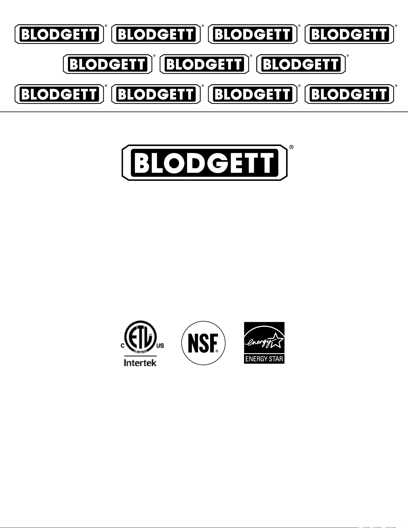
Cooking in a convection oven diers from cooking in a
conventional deck or range oven since heated air is con-
stantly recirculated over the product by a fan in an en-
closed chamber. The moving air continually strips away
the layer of cool air surrounding the product, quickly al-
lowing the heat to penetrate. The result is a high qual-
ity product, cooked at a lower temperature in a shorter
amount of time.
Blodgett convection ovens represent the latest advance-
ment in energy eciency, reliability, and ease of opera-
tion. Heat normally lost, is recirculated within the cooking
chamber before being vented from the oven: resulting in
substantial reductions in energy consumption and en-
hanced oven performance.
Air Flow Pattern for Blodgett Electric Convection Ovens
Figure 1

3
Installation
Delivery and Location
DELIVERY AND INSPECTION
All Blodgett ovens are shipped in containers to prevent
damage. Upon delivery of your new oven:
• Inspect the shipping container for external damage.
Any evidence of damage should be noted on the
delivery receipt which must be signed by the driver.
• Uncrate the oven and check for internal damage.
Carriers will accept claims for concealed damage if
notied within fteen days of delivery and the ship-
ping container is retained for inspection.
The Blodgett Oven Company cannot assume responsibil-
ity for loss or damage suered in transit. The carrier as-
sumed full responsibility for delivery in good order when
the shipment was accepted. We are, however, prepared
to assist you if ling a claim is necessary.
OVEN LOCATION
The well planned and proper placement of your oven will
result in long term operator convenience and satisfactory
performance.
The following clearances must be maintained between
the oven and any combustible or non-combustible con-
struction.
Mark V-100-K12
• Oven body right side - 1” (2.5 cm)
• Oven body left side - 1” (2.5 cm)
• Oven body back - 1” (2.5 cm)
• Single and stacked oven bottom - 1/2” (1.2 cm)
Mark V-200-K12
• Oven body right side - 1/2” (1.3 cm)
• Oven body left side - 1/2” (1.3 cm)
• Oven body back - 1/2” (1.3 cm)
• Single and stacked oven bottom - 1/2” (1.3 cm)
The following clearances must be available for servicing.
• Oven body sides - 12” (30 cm)
• Oven body back - 12” (30 cm)
It is essential that an adequate air supply to the oven be
maintained to provide a sucient ow of combustion and
ventilation air.
• Place the oven in an area that is free of drafts.
• Keep the oven area free and clear of all combus-
tibles such as paper, cardboard, and ammable
liquids and solvents.
• Do not place the oven on a curb base or seal to
a wall. This will restrict the ow of air and prevent
proper ventilation. Tripping of the blower motor’s
thermal overload device is caused by an excessive
ambient temperature on the right side of the oven.
This condition must be corrected to prevent perma-
nent damage to the oven.
Before making any utility connections to this oven, check
the rating plate to be sure the oven specications are
compatible with the electrical services supplied for the
oven.
1. Pull out control panel. The rating plate attached to the
inside of the control compartment.
• Do not place strong sources of heat such as open
ame ranges, griddles, or charbroilers near the
oven. If such an instance exists, it is highly recom-
mended to purchase a heat shield, available from
Blodgett.
• Note that if temperatures are too high, a safety shut-
down may occur.
• Failure to comply may invalidate the oven warranty.
4
Installation
Oven Assembly
NSF BOLTS
These bolts are required by NSF to block any exposed
hole on the back of an oven. This includes:
• any unit, single or stacked, without a back panel.
• any holes in stacked units not used for mounting
stacking brackets.
1. Locate the 5/16” bolts that were shipped with the
oven.
2. Install the bolts as shown.
Figure 2
Double Stacked Units Units without back panels
5
Installation
Oven Assembly
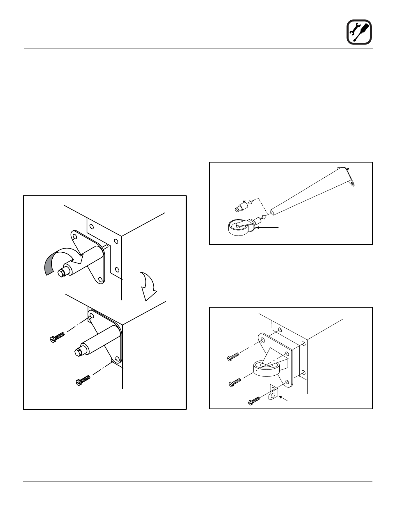
LEG ATTACHMENT
1. Push the oven onto a lift with the bottom of the oven
down.
2. Align the threaded stud in each leg with the nut locat-
ed inside each bottom corner of the oven frame. Turn
the legs clockwise and tighten to the nearest full turn.
3. Align the two leg plate holes in each leg with those
in the oven bottom. Secure each leg using two 1/2”
bolts.
NOTE: If using casters see CASTER ASSEMBLY
before proceeding.
4. Level the oven by screwing the adjustable leg feet in
or out as necessary.
6” (15 cm) Legs Shown
Figure 3
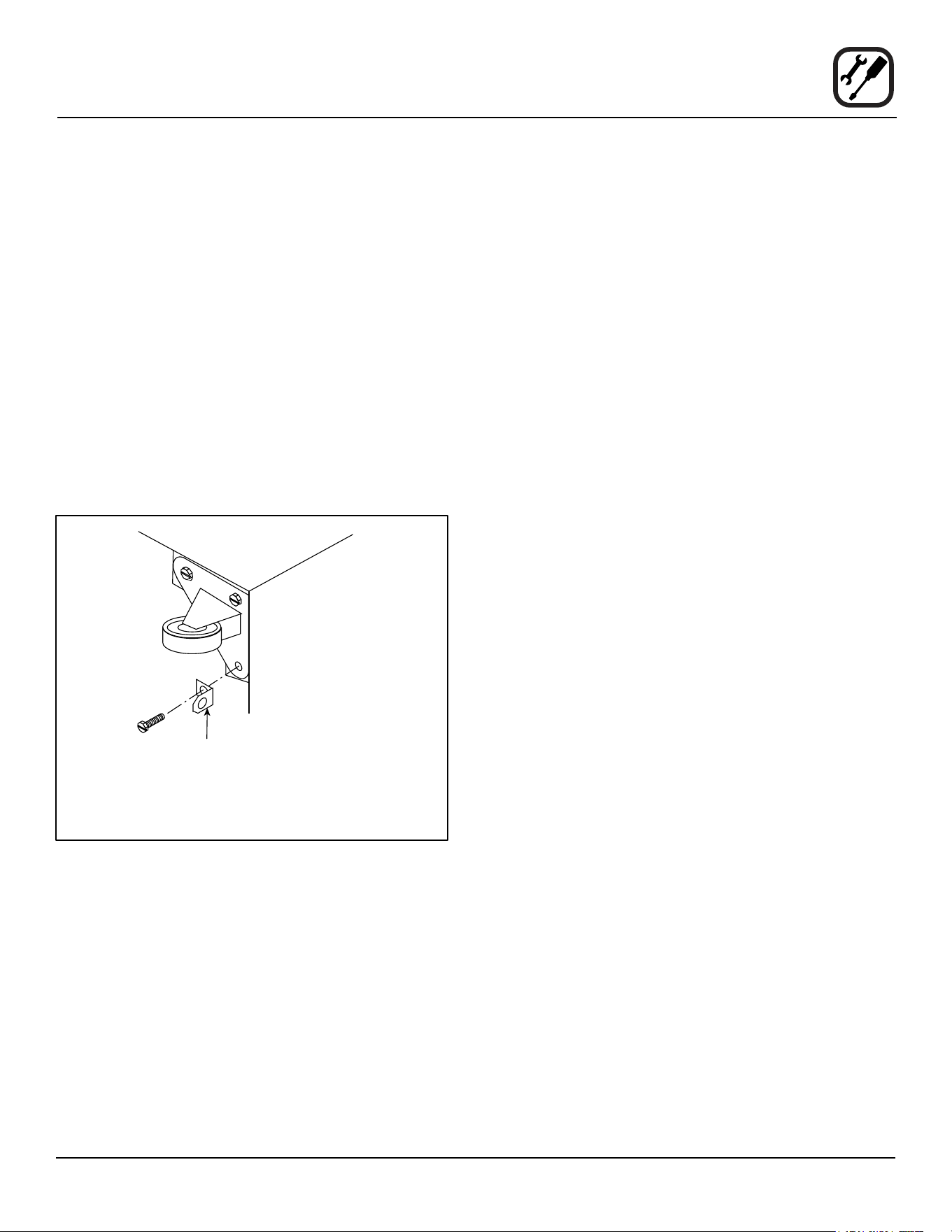
CASTER ASSEMBLY
NOTE: Install the locking casters on the front of the
oven. Install the non-locking casters on the back
of the oven.
Casters for Single and Double Stacked Ovens:
1. Attach the legs as described.
2. Pry the adjustable feet out of the legs
3. Insert one caster into each leg as shown. Tighten the
lock nuts to secure the casters.
Adjustable
Leg Foot
Caster Assembly
25” (64 cm) Legs Shown
Figure 4
Low Prole Casters for Double Stacked Ovens:
1. Align the three holes in each caster assembly plate
with those in the oven bottom. Secure each caster
using three 1/2” bolts.
Figure 5
6
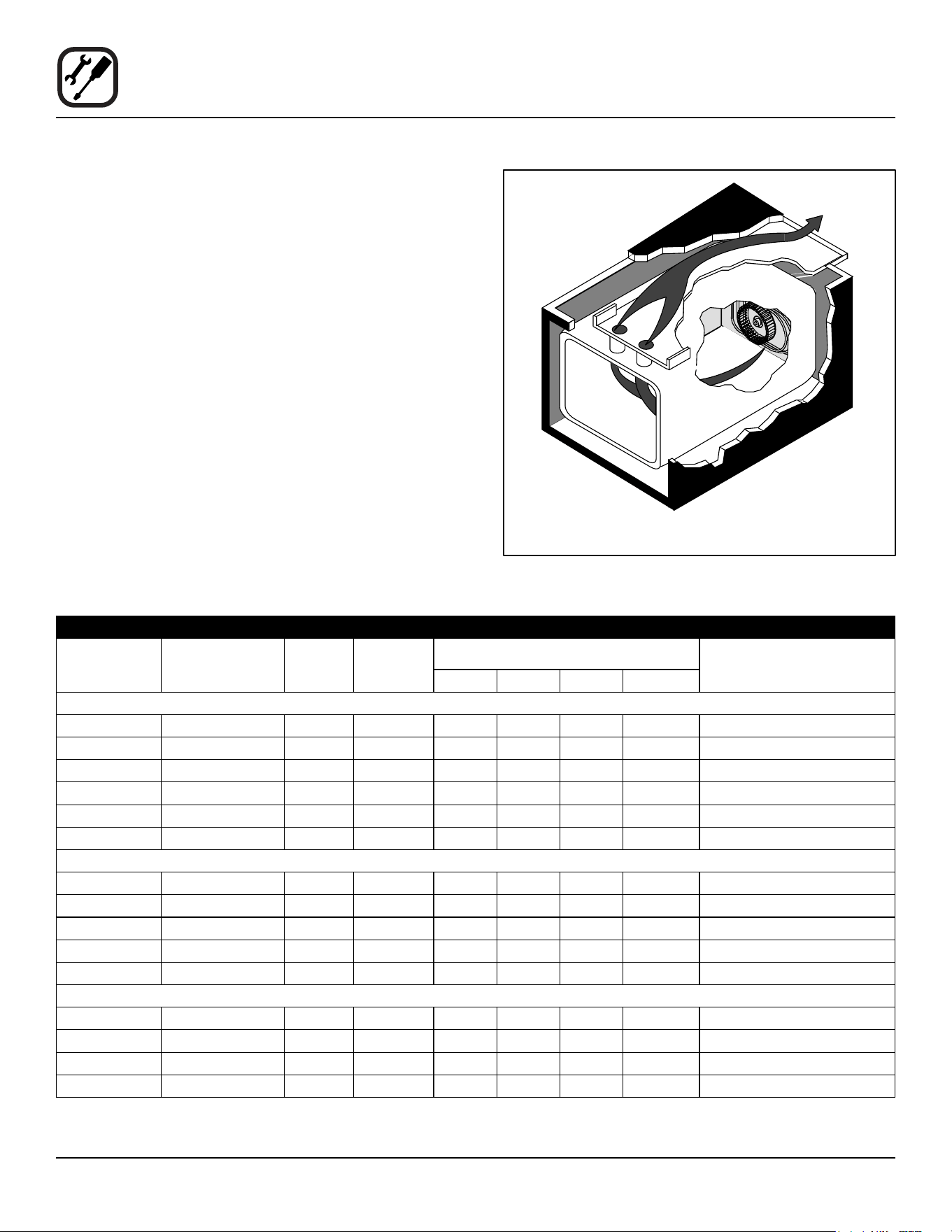
Installation
Oven Assembly
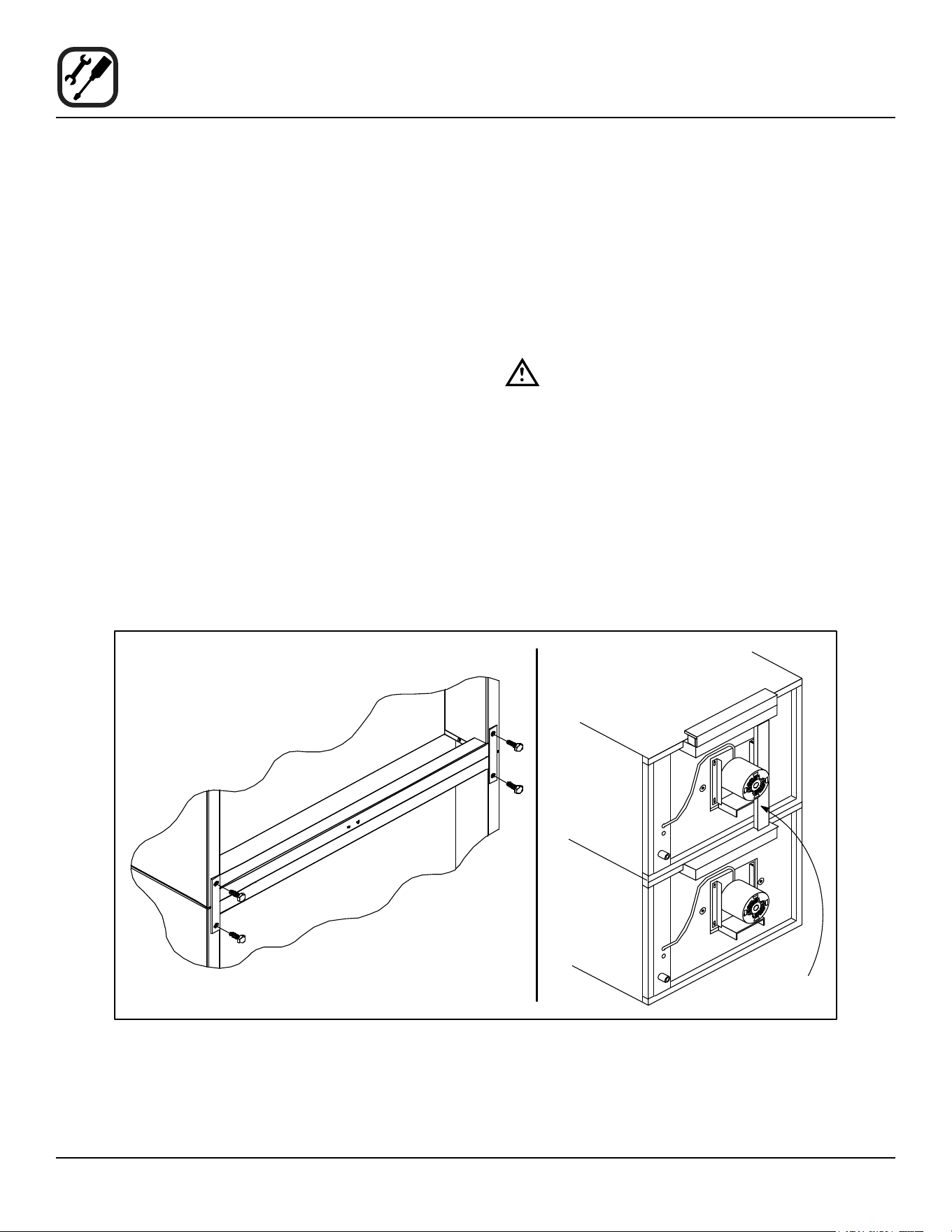
DOUBLE SECTION ASSEMBLY
NOTE: Old style ovens refer to units with painted ex-
posed rear angle. New style ovens refer to units
with rear angle iron enclosed in steel.
The following instructions apply to stacking two new style
ovens.
1. Secure the short legs to the bottom sections as de-
scribed.
2. Place the upper section in position on top of the lower
oven.
3. Attach the stacking brackets using the remaining
5/16” bolts shipped with the ovens.
4. Attach the ue connector.
The following instructions apply to stacking a new style
oven on an old style oven.
1. Secure the short legs to the bottom sections as de-
scribed.
2. Place the upper section in position on top of the lower
oven.
3. Attach the stacking brackets using the remaining
5/16” bolts shipped with the ovens.
4. Drill a clearance hole for a 5/16” bolt in the angle iron
of the old style oven. Use the holes in the stacking
brackets as a pilot.
5. Attach the stacking brackets to the old style oven with
the 5/16” bolts and nuts provided in the kit.
6. Attach the ue connector.
WARNING!!
When stacking ovens be sure to remove the
single oven ue boxes prior to attaching
three-piece connector.
OVEN LEVELING
After assembly, the oven should be leveled and moved to
the operating location.
1. The oven can be leveled by adjusting the feet or cast-
ers located on the bottom of each leg.
Flue
Connector
Figure 6
7
Installation
Utility Connections - Standards and Codes
THE INSTALLATION INSTRUCTIONS CONTAINED
HEREIN ARE FOR THE USE OF QUALIFIED INSTAL-
LATION AND SERVICE PERSONNEL ONLY. INSTAL-
LATION OR SERVICE BY OTHER THAN QUALIFIED
PERSONNEL MAY RESULT IN DAMAGE TO THE OVEN
AND/OR INJURY TO THE OPERATOR.
Qualied installation personnel are individuals, a rm,
a corporation, or a company which either in person or
through a representative are engaged in, and responsible
for:
• the installation of electrical wiring from the electric
meter, main control box or service outlet to the elec-
tric appliance.
Qualied installation personnel must be experienced in
such work, familiar with all precautions required, and have
complied with all requirements of state or local authorities
having jurisdiction.
U.S. and Canadian installations
All ovens, when installed, must be electrically grounded
in accordance with local codes, or in the absence of lo-
cal codes, with the National Electrical Code, ANSI/NFPA
70-Latest Edition and/or Canadian National Electric Code
C22.2 as applicable.
The ventilation of this oven should be in accordance with
local codes. In the absence of local codes, refer to the
National ventilation code titled, “Standard for the Installa-
tion of Equipment for the Removal of Smoke and Grease
Laden Vapors from Commercial Cooking Equipment”,
NFPA-96-Latest Edition.
General export installations
Installation must conform with Local and National instal-
lation standards. Local installation codes and/or require-
ments may vary. If you have any questions regarding the
proper installation and/or operation of your Blodgett oven,
please contact your local distributor. If you do not have a
local distributor, please call the Blodgett Oven Company
at 0011-802-658-6600.
8
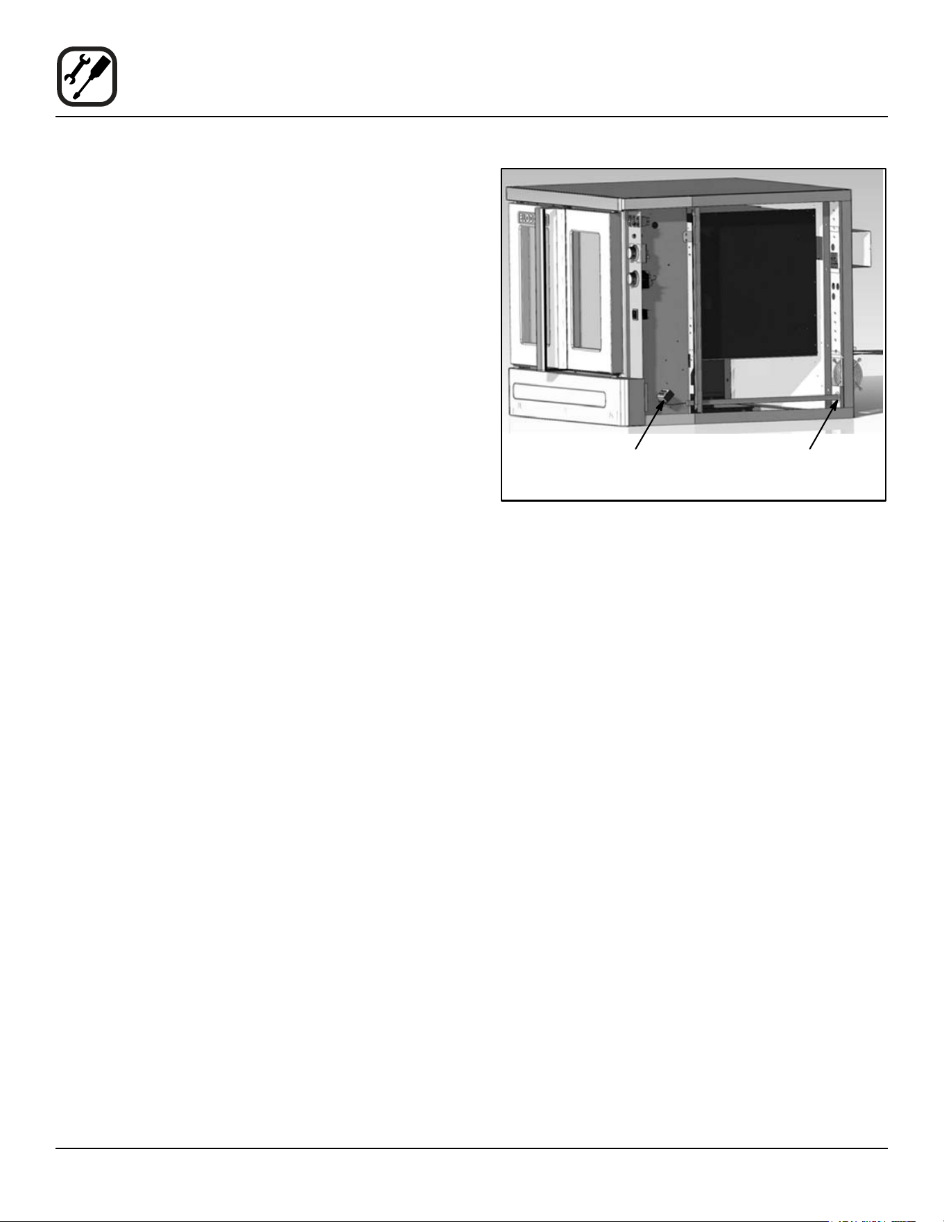
Installation
Electrical Connection
Wiring diagrams are located in the control compartment
and on the back of the oven.
The electric motor, indicator lights and related switches
are connected to the oven as follows:
The service line will enter trough the rear of the oven and
connected to the terminal block (see diagram).
1. Remove the bottom trim and control panel. Removal
of the body side is not necessary.
2. Remove knock-out in the rear of the unit and run the
supply power line to terminal block and connect the
wires.
3. Reinstall the control panel and the bottom trim.
NOTE: To prevent damage there is no power to the
heating elements when the blower is not operat-
ing.
THE BLODGETT OVEN COMPANY CANNOT ASSUME
RESPONSIBILITY FOR LOSS OR DAMAGE SUFFERED
AS A RESULT OF IMPROPER INSTALLATION.
Connect wires to
terminal block
Run supply line through
the knock-out
Figure 7
9
Installation
Intial Startup
OVEN RESTRAINT
If casters are used in conjunction with a power supply
cord for movable appliances, a xed restraint should be
provided.
The restraint (ie: heavy gauge cable) should be attached
without damaging the building. DO NOT use the gas pip-
ing or electrical conduit for the attachment of the perma-
nent end of the restraint! Use anchor bolts in concrete or
cement block. On wooden walls, drive hi test wood lag
screws into the studs of the wall.
If the oven is moved from its regular location, the restraint
must be reconnected when the oven is returned.
1. Mount the supplied bracket to the leg bolt just below
the power cord.
2. Attach the clip on restraining cable to the mounting
bracket.
Back of Oven
Restraint Cable
Bracket
Double stacked unit shown. Use the same
procedure for single units.
Figure 8
ADJUSTMENTS ASSOCIATED WITH INITIAL INSTAL-
LATION
Each oven, and its component parts, have been thorough-
ly tested and inspected prior to shipment. However, it is
often necessary to further test or adjust the oven as part
of a normal and proper installation. These adjustments
are the responsibility of the installer, or dealer. Since
these adjustments are not considered defects in mate-
rial or workmanship, they are not covered by the Original
Equipment Warranty. They include, but are not limited to:
• calibration of the thermostat
• adjustment of the doors
• leveling
• tightening of fasteners.
No installation should be considered complete without
proper inspection, and if necessary, adjustment by quali-
ed installation or service personnel.

10
Operation
Safety Information
The information contained in this section is provided for
the use of qualied operating personnel. Qualied operat-
ing personnel are those who have carefully read the in-
formation contained in this manual, are familiar with the
functions of the oven and/or have had previous experi-
ence with the operation of the equipment described. Ad-
herence to the procedures recommended herein will as-
sure the achievement of optimum performance and long,
trouble-free service.
Please take the time to read the following safety and op-
erating instructions. They are the key to the successful
operation of your Blodgett oven.
SAFETY TIPS
For your safety read before operating
General safety tips:
• If the oven needs to be moved for any reason, the
supply cord must be disconnected from the unit
before removing the restraint cable. Reconnect the
restraint after the oven has been returned to its
original location.
• DO NOT remove the control panel cover unless the
oven is unplugged.
11
Operation
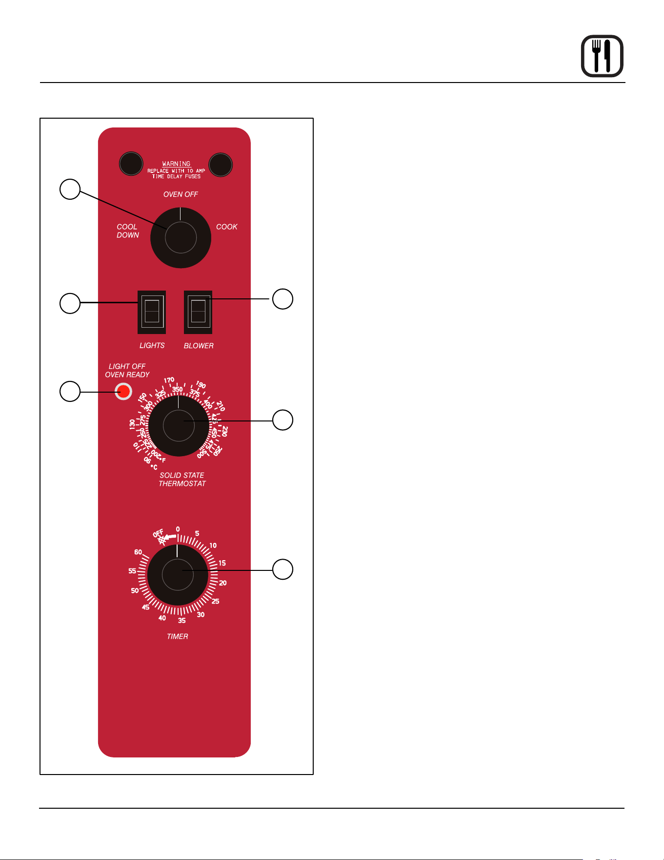
SSI-M Solid State Innite Control with Manual Timer
OFF
ON
LO
HI
1
3
4
2
5
6
Figure 9
CONTROL DESCRIPTION
1. SELECTOR SWITCH - controls power to the oven for
cook or cool down.
2. BLOWER SWITCH - controls blower speed, either hi
or lo.
3. LIGHTS SWITCH - controls interior lights.
4. OVEN READY LIGHT - when lit indicates elements
are heating. When the light goes out the oven has
reached operating temperature.
5. SOLID STATE THERMOSTAT - allows either 8 pre-
set temperatures to be selected in accordance with
customer requirements, or an innite selection of
temperatures from 200-500_F (95-260_C). (innite
control shown)
6. TIMER - activates an electric buzzer that sounds
when the cook time expires.
OPERATION
1. Turn the SELECTOR Switch (1) to COOK. The blower
and control compartment cooling fan operate and are
controlled automatically by the action of the doors.
2. Set BLOWER Switch (2) to the desired speed.
3. Set the SOLID STATE THERMOSTAT (5) to the de-
sired setting or temperature.
4. Preheat until the OVEN READY LIGHT (4) goes out.
5. Load product into the oven. Determine cook time and
set the TIMER (6).
6. When the buzzer sounds, remove the product from
the oven. Turn the TIMER knob (6) to OFF to silence
the buzzer.
7. Turn the SELECTOR Switch (1) to OVEN OFF.
12
Operation
SSI-D Solid State Innite Control with Digital Timer
CIRCUIT
BREAKER
1
3
4
2
5
6
7
8
Figure 10
CONTROL DESCRIPTION
1. SELECTOR SWITCH - controls power to the oven for
cook or cool down.
2. BLOWER SWITCH - controls blower speed, either hi
or lo.
3. LIGHTS SWITCH - controls interior lights.
4. OVEN READY LIGHT - when lit indicates burner op-
eration. When the light goes out the oven has reached
operating temperature.
5. SOLID STATE THERMOSTAT - allows an innite se-
lection of temperatures from 150-500°F (66-260°C).
6. DISPLAY - displays cook time
7. TIMER DIAL - used to enter desired cook time
8. HEAT CUTOFF - circuit breaker
OPERATION
1. Turn the SELECTOR Switch (1) to COOK. The blower
and control compartment cooling fan operate and are
controlled automatically by the action of the doors.
The display reads 00:00.
2. Set BLOWER Switch (2) to the desired speed.
3. Set the SOLID STATE THERMOSTAT (5) to the de-
sired temperature.
4. Preheat until the OVEN READY LIGHT (4) goes out.
5. Load product into the oven. Rotate the dial (7) to the
desired time. The timer will begin to countdown after
approximately 1 second.
6. When the buzzer sounds, remove the product from
the oven. Turn the TIMER dial (7) to silence the buzz-
er.
7. Turn the SELECTOR Switch (1) to OVEN OFF.

13
Operation
General Guidelines for Operating Personnel
COOK TIMES AND TEMPERATURES
Preheating the oven
Always preheat the oven before baking or roasting. We
recommend preheating 50°F (28°C) above the cook tem-
perature to oset the drop in temperature when the doors
are opened and cold product is loaded into the oven. Set
the thermostat to the cook temperature after the product
is loaded.
NOTE: For frozen product, preheat the oven 100°F
(56°C) above the cook temperature.
Cook Temperatures
Generally, cook temperatures should be 50°F (28°C) low-
er than deck or range oven recipes. If the edges of the
product are done but the center is raw, or if there is color
variation, reduce the thermostat setting another 15-25°F
(10-15°C). Continue to reduce the cook temperature on
successive loads until the desired results are achieved.
NOTE: Cooking at excessive temperatures will not
reduce cook time, it will produce unsatisfactory
baking and roasting results.
Cook Time
Check the product in about half the time recommended
for deck or range oven recipes. Record times and tem-
peratures which provide best results for future reference.
NOTE: Cook time will vary with the amount of product
loaded, the type of pan and the temperature.
OPERATING TIPS
Pans and Racks
Product or pan height determines how many racks are
used. The oven holds up to ten 18” x 26” (45.7 x 66.0 cm)
bun pans.
Load the oven from the bottom, centering the pans on the
rack. Never place a pan or aluminum foil on the bottom
of the oven. This obstructs the ow of air and results in
uneven baking and roasting.
Roasting
To reduce shrinkage when roasting, place meat directly on
the racks. Place a sheet pan one-half full of water in the
bottom rack position. The water evaporates, increasing
humidity in the oven chamber. The pan catches grease
from the meat, making oven cleaning easier.
Baking
Weigh the product to ensure equal distribution in each
pan. Varying amounts of product will cause uneven bak-
ing results.
Fans
The fan must be operating for the oven to heat. Use the
Pulse Plus feature to allow light or liquid product to set
in the pan and to avoid rippling towards the fan. If your
oven is not equipped with this feature use the following
procedure.
1. Preheat the oven 25°F (15°C) above the baking tem-
perature.
2. Load the oven with product. Close the doors.
3. Set the thermostat to the baking temperature.
4. Turn the oven o.
5. Allow the product to set for 5-7 minutes with the fan
o. The residual heat in the oven sets the product.
6. Turn the oven on for the remainder of the bake.
Lights
Turn the oven lights o when not viewing the product.
Leaving the lights on for extended periods of time short-
ens the bulb life considerably.
14
Operation
Suggested Times and Temperatures
PRODUCT TEMPERATURE TIME # SHELVES
Meats
Hamburger Patties (5 per lb)
Steamship Round (80 lb. quartered)
Standing Rib Choice (20 lbs, trimmed, rare)
Banquet Shell Steaks (10 oz. meat)
Swiss Steak after Braising
Baked Stued Pork Chop
Boned Veal Roast (15 lbs.)
Lamb Chops (small loin)
Bacon (on racks in 18” x 26” pans)
400°F (205°C)
275°F (135°C)
235°F (115°C)
450°F (235°C)
275°F (135°C)
375°F (190°C)
300°F (150°C)
400°F (205°C)
400°F (205°C)
8-10 mins.
2 hrs 45 mins.
2 hrs 45 mins.
7-8 mins.
1 hr.
25-30 mins.
3 hrs. 10 mins.
7-8 mins.
5-7 mins.
10
2
2
5
5
5
2
5
10
Poultry
Chicken Breast & Thigh
Chicken Back & Wing
Chicken (21/2 lbs. quartered)
Turkey Rolled (18 lb. rolls)
350°F (175°C)
350°F (175°C)
350°F (175°C)
310°F (155°C)
40 mins.
35 mins.
30 mins.
3 hrs 45 mins.
5
5
5
3
Fish and Seafood
Halibut Steaks, Cod Fish (frozen 5 oz)
Baked Stued Lobster (21/2 lb.)
Lobster Tails (frozen)
350°F (175°C)
400°F (205°C)
425°F (220°C)
20 mins.
10 mins.
9 mins.
5
3
5
Cheese
Macaroni & Cheese Casserole
Melted Cheese Sandwiches
350°F (175°C)
400°F (205°C)
30 mins.
8 mins.
5
10
Potatoes
Idaho Potatoes (120 ct.)
Oven Roasted Potatoes (sliced or diced)
400°F (205°C)
325°F (165°C)
50 mins.
10 mins.
5
5
Baked Goods
Frozen Berry Pies (22 oz)
Fresh Apple Pie (20 oz.)
Pumpkin Pies (32 oz.)
Fruit Crisp
Bread (24 - 1 lb. loaves)
Southern Corn Bread
Baking Soda Biscuits
Brown & Serve Rolls
Sheet Cakes (5 lb. mixed batter per pan)
Chocolate Cake
Brownies
325°F (150°C)
350°F (175°C)
300°F (150°C)
300°F (150°C)
325°F (155°C)
375°F (190°C)
400°F (205°C)
350°F (175°C)
325°F (160°C)
325°F (160°C)
325°F (150°C)
35 mins.
25-30 mins.
30-50 mins.
25 mins.
30 mins.
15-20 mins.
6 mins.
15 mins.
16-18 mins.
20 mins.
15 mins.
5 (30 pies)
5 (30 pies)
5 (20 pies)
5
3
5
5
5
5
5
5
NOTE: Actualtimesandtemperaturesmayvaryconsiderablyfromthoseshownabove.Theyareaectedbyweightof
load, temperature of the product, recipe, type of pan and calibration of thermostat. Should your recipe vary, write
in your proven time and temperature for ready reference.

15
Maintenance
Cleaning and Preventative Maintenance
CLEANING THE OVEN
Painted and stainless steel ovens may be kept clean and
in good condition with a light oil.
1. Saturate a cloth, and wipe the oven when it is cold.
2. Dry the oven with a clean cloth.
On the stainless front or interiors, deposits of baked on
splatter may be removed with any non-toxic industrial
stainless steel cleaner. Heat tint and heavy discoloration
may be removed with any non-toxic commercial oven
cleaner.
1. Apply cleaners when the oven is cold. Always rub
with the grain of the metal.
The porcelain interior can be cleaned with any commer-
cial oven cleaner. Be sure caustic cleaning compounds
DO NOT come in contact with the blower wheel and the
aluminized steel panel directly behind it.
1. Remove the racks, rack supports and blower wheel
from the oven.
2. Soak the parts in a solution of ammonia and water.
3. Reinstall after cleaning.
NOTE: If the oven is moved the restraint must be recon-
nected after the unit is returned to it’s regular
position.
Nettoyage hebdomadaire
En plus du nettoyage quotidien, il est nécessaire de net-
toyer les prises d’air sur une base hebdomadaire. Les
prises d’air fournissent l’air de refroidissement nécessaire
aux composants internes. Ils sont généralement situés à
l’arrière et sur les côtés de l’équipement.
PREVENTATIVE MAINTENANCE
The best preventative maintenance measures are, the
proper installation of the equipment and a program for
routinely cleaning the ovens.
Annual Maintenance
This oven requires no lubrication, however, the venting
system should be checked annually for possible deterio-
ration resulting from moisture and corrosive ue products.
If maintenance or repairs are required, contact your local
Blodgett service company, a factory representative or the
Blodgett Oven company.
WARNING!!
Always disconnect the appliance from the
power supply before servicing or cleaning.
16
Maintenance
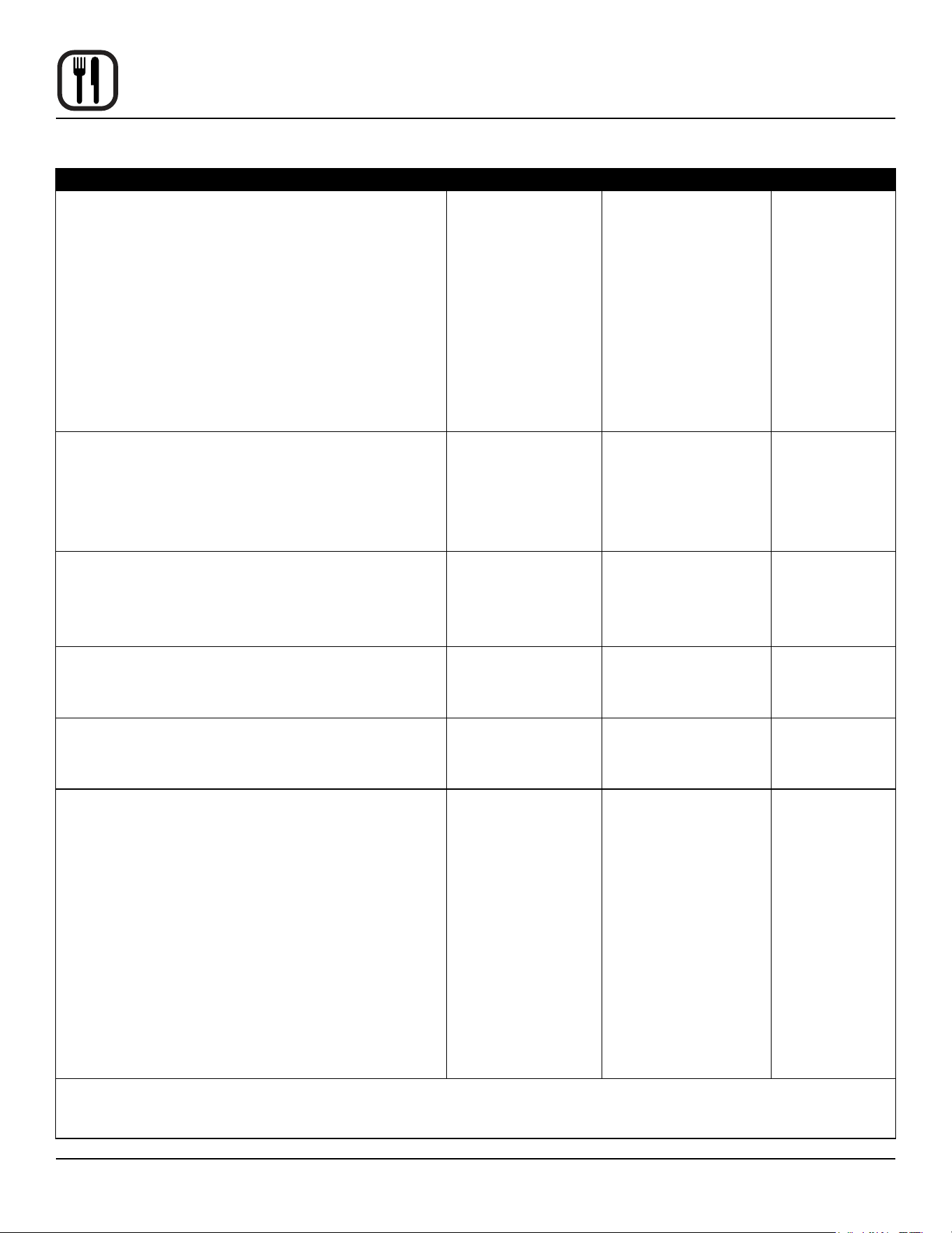
Troubleshooting Guide
POSSIBLE CAUSE(S) SUGGESTED REMEDY
SYMPTOM: Heating elements do not come on.
• Oven not plugged in.
• Power switch on the control panel is o.
• Control set below ambient temperature.
• Doors are open.
• Computerized controls - error code on display.
• Plug in electrical supply cord.
• Set the control panel to COOK or OVEN ON.
• Set to desired cook temperature.
• Close doors.
• *
SYMPTOM: Oven does not come to ready.
• The oven has not reached preheat temperature.
• Fan delay feature may be activated, if applicable.
• Internal problem with main temperature control.
• Wait for oven to reach preheat temperature.
• Deactivate fan delay feature.
• *
SYMPTOM: Convection fan does not run.
• Oven is not plugged in.
• Oven is not set to the cook mode.
• Circuit breaker tripped.
• Fan delay feature may be activated, if applicable.
• Doors are open
• Plug in electrical supply cord.
• Set the control panel to COOK or OVEN ON.
• Reset the breaker.
• Deactivate fan delay feature.
• Close doors.
SYMPTOM: General baking problems.
• Computerized controls - incorrect product program-
ming.
• Thermostat out of calibration.
• Reprogram control per Operation section.
• *
*Denotesremedyisadicultoperationandshouldbeperformedbyqualiedpersonnelonly.Itisrecommended,how-
ever, that All repairs and/or adjustments be done by your local Blodgett service agency and not by the owner/operator.
Blodgettcannotassumeresponsibilityfordamageasaresultofservicingdonebyunqualiedpersonnel.
WARNING!!
Always disconnect the power supply before cleaning or servicing the oven.