Residential Gas
Water Heater
Installa on Instruc ons and
Use & Care Guide
Keep this manual in the pocket on heater for future reference whenever maintenance, adjustment or service is required.
Retain your original receipt as proof of purchase.
Power Vented Ultra Low Nox Gas Water Heater with the
Flammable Vapor Igni on Resistant Safety System
Read this manual and the labels on the water heater before you install,
operate, or service it. If you have diffi culty following the direc ons, or
aren’t sure you can safely and properly do any of this work yourself:
• Call our Technical Assistance Hotline which is listed on your warranty. We can
help you with installa on, opera ons, troubleshoo ng, or maintenance. Before
you call, write down the model and serial number from the water heater’s ra ng
plate.
• Incorrect installa on, opera on, or service can damage the water heater, your
house and other property, and present risks including fi re, scalding, electric
shock, and explosion, causing serious injury or death.
Do not store or use gasoline or other
fl ammable vapors and liquids in the
vicinity of this or any other appliance.
WHAT TO DO IF YOU SMELL GAS
• Do not try to light any appliance.
• Do not touch any electrical switch;
do not use any phone in your build-
ing.
• Immediately call your gas supplier
from a neighbor’s phone. Follow the
gas supplier’s instruc ons.
• If you cannot reach your gas sup-
plier, call the fi re department.
Installa on and service must be per-
formed by a qualifi ed installer, service
agency or the gas supplier.
WARNING: If the informa on in
these instruc ons is not followed
exactly, a fi re or explosion may
result causing property damage,
personal injury or death.
LOW LEAD
CONTENT
Table of Contents Page
IMPORTANT SAFETY INFORMATION ..........................................3-6
GETTING STARTED ...................................................................7-15
INSTALLATION ........................................................................ 16-26
OPERATION ............................................................................27-28
TROUBLESHOOTING .............................................................29-34
MAINTENANCE ...................................................................... 35-37
ELECTRICAL CONNECTIONS ........................................................ 38
REPAIR PARTS ........................................................................39-40
100362953_2000618730 (REV. A)
March 2023
Printed on: 7/6/2023 9:40:13 AM CT
2 • Power Vented Ultra Low Nox Gas Water Heater - Use and Care Guide
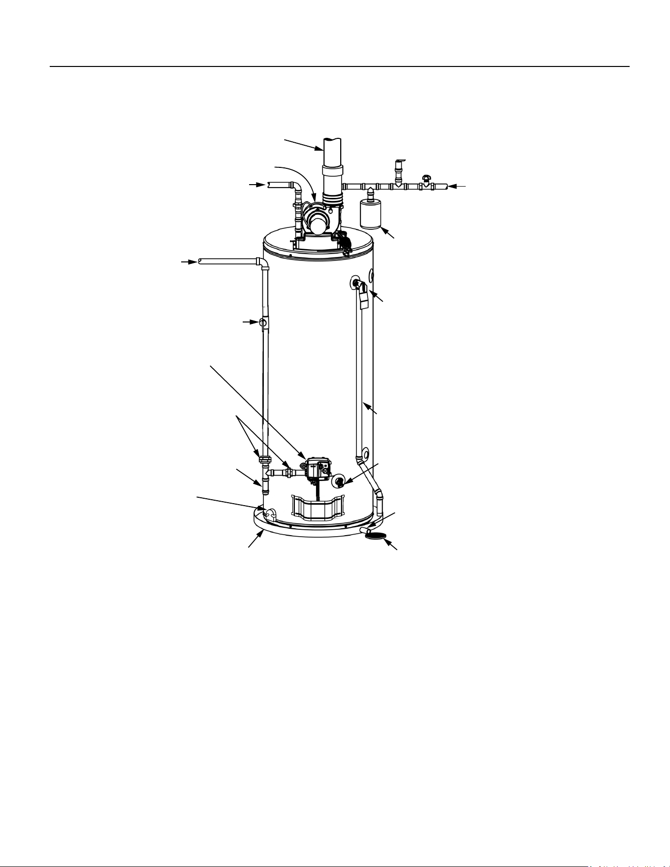
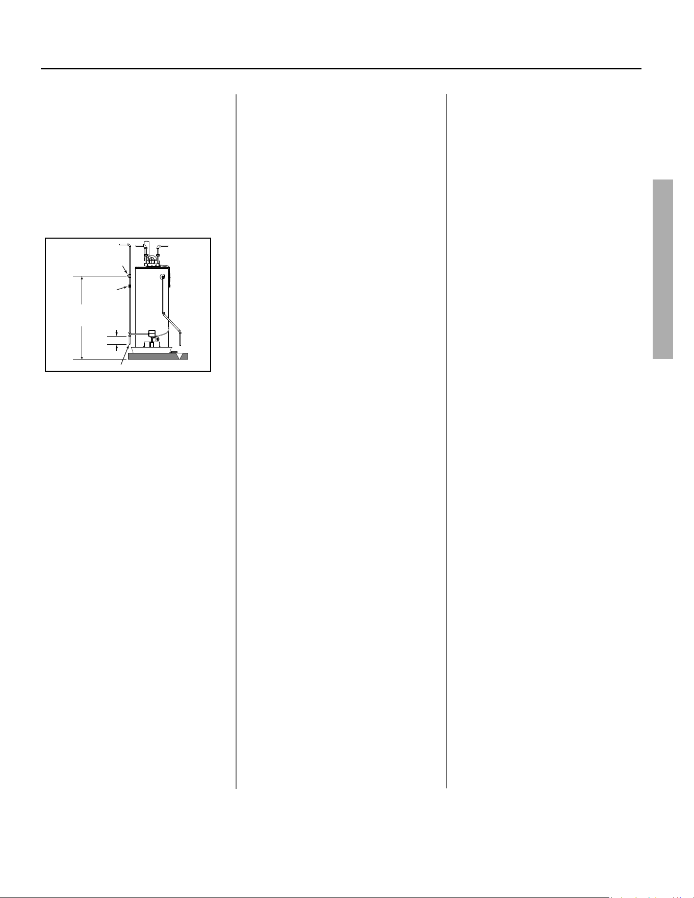
COMPLETED INSTALLATION TYPICAL
Hot water line
Vent Pipe
Cold water line
Expansion tank
(Connected to cold water inlet)
Blower
T&P relief valve
T&P discharge pipe
Drain
Metal drain pan
discharge pipe
Drain valve
Metal drain pan
Sediment trap
Gas Supply
'ĂƐƐƵƉƉůLJƐŚƵƚŽī
Gas control valve/
thermostat
Ground Joint Union
FV Sensor
Printed on: 7/6/2023 9:40:13 AM CT
Power Vented Ultra Low Nox Gas Water Heater - Use and Care Guide • 3
IMPORTANT SAFETY INFORMATION
Important informa on to keep
Fill out this sec on and keep this
manual in the pocket of the water
heater for reference.
Date Installed:
Model number:
Serial number:
Maintenance performed:* Date:
This is the safety alert symbol. It is used to alert you to
poten al physical injury hazards. Obey all safety mes-
sages that follow this symbol to avoid possible property
damage, serious injury or death. Do not remove any per-
manent instruc ons, labels, or the ra ng plate from either the outside of
the water heater or on the inside of the access panels. Keep this manual
near the water heater.
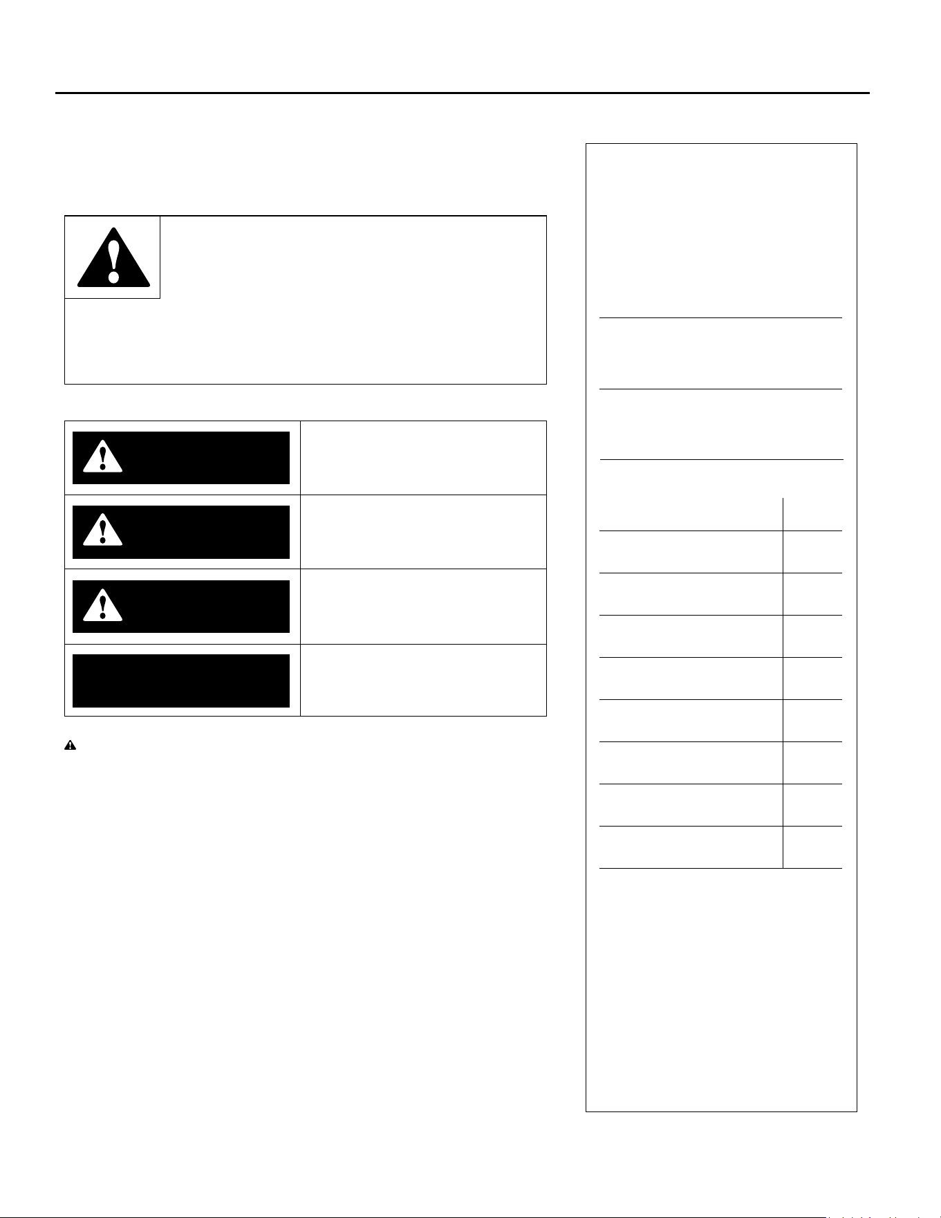
DANGER
Read and follow all safety messages and instruc ons in
this manual.
DANGER indicates hazardous situa-
on that, if not avoided, will result
in death or serious injury.
WARNING
WARNING indicates a hazardous
situa on that, if not avoided, could
result in death or serious injury.
CAUTION
CAUTION indicates a hazardous
situa on that, if not avoided, could
result in minor or moderate injury.
NOTICE
NOTICE indicates prac ces not
related to physical injury.
WARNING! If the informa on in these instruc ons is not followed exactly,
a fi re or explosion may result causing property damage, personal injury or
death. Do not store or use gasoline or other fl ammable vapors and liquids in
the vicinity of this or any other appliance.
An odorant is added by the gas supplier to the gas used by this water heater.
This odorant may fade over an extended period of me. Do not depend upon
this odorant as an indica on of leaking gas. We recommend installing a fuel gas
and carbon monoxide detector.
This product is cer fi ed to comply with a maximum weighted average of 0.25%
lead content as required in some areas.
*Drain and fl ush tank and remove and
inspect anode rod a er fi rst six months
of opera on and at least annually
therea er. Operate the Temperature
and Pressure Relief Valve (T&P) annu-
ally and inspect T&P valve every 2-4
years (see the label on the T&P valve for
maintenance schedule). See the Main-
tenance sec on for more informa on
about maintaining this water heater.
Printed on: 7/6/2023 9:40:13 AM CT
4 • Power Vented Ultra Low Nox Gas Water Heater - Use and Care Guide
SAFETY
IMPORTANT SAFETY INFORMATION
T
o reduce the risk of property
damage, serious injury or death,
read and follow the precau ons below,
all labels on the water heater, and
the safety messages and instruc ons
throughout this manual.
RISKS DURING
INSTALLATION AND
MAINTENANCE
Li ing Risk
WARNING! The
water heater is heavy.
Follow these precau-
ons to reduce the
risk of property damage, injuries from
li ing or impact injuries from dropping
the water heater.
• Use at least two people to li the
water heater.
• Be sure you both have a good grip
before li ing.
• Use an appliance dolly or hand
truck to move the water heater.
Explosion Risk
WARNING! Read the water heater’s
ra ng plate to determine the type of
gas required. Failure to follow these
instruc ons can result in serious injury
or death from explosion, fi re or
carbon monoxide poisoning.
• Do not connect a natural gas water
heater to an L.P. gas supply.
• Do not connect an L.P. gas water
heater to a natural gas supply.
• Use a new CSA approved gas
supply line.
• Install a shut-off valve on the gas
supply line.
Gas Pressure
WARNING! The gas supply pressure
must not exceed the maximum supply
pressure as stated on the water
heater’s ra ng plate. The minimum
supply pressure is for the purpose of
input adjustment.
RISKS DURING
OPERATION
Scalding Risk
This water heater
can make water hot
enough to cause severe burns instantly,
resul ng in severe injury or death.
• Feel water before bathing or
showering.
• To reduce the risk of scalding,
install Thermosta c Mixing Valves
(temperature limi ng valves) at
each point-of-use. These valves
automa cally mix hot and cold
water to limit the temperature at
the tap. Mixing valves are avail-
able from your local plumbing
supplier. Follow manufacturer’s
instruc ons for installa on and
adjustment of the valves.
• The gas control valve on this water
heater has been factory set to its
lowest se ng to reduce the risk
of scalding. Higher temperatures
increase the risk of scalding, but
even at 120°F, hot water can scald.
If you choose a higher tempera-
ture se ng, Thermosta c Mixing
Valves located at each point-of-use
are par cularly important to help
avoid scalding.
Table 1
Temperature
Time to Produce
a Serious Burn
120°F (49°C) More than 5 minutes
125°F (52°C) 1½ to 2 minutes
130°F (54°C) About 30 seconds
135°F (57°C) About 10 seconds
140°F (60°C) Less than 5 seconds
145°F (63°C) Less than 3 seconds
150°F (66°C) About 1½ seconds
155°F (68°C) About 1 second
For informa on about changing the
factory temperature se ng, refer to
“Adjus ng the Temperature” on page
28.
Even if you set the water heater’s gas
control valve to a low se ng, higher
water temperatures may occur in cer-
tain circumstances:
• In some cases, repeated small draws
of water can cause the hot and cold
water in the tank to “stack” in layers.
If this happens, the water can be as
much as thirty degrees ho er than
the gas control valve se ng. This
temperature varia on is the result
of your usage pa ern and is not a
malfunc on.
• Water temperature will be ho er if
someone adjusted the gas control
valve to a higher se ng.
• Problems with the gas control valve
or other malfunc ons may result in
higher than expected water tem-
peratures.
• If the water heater is in a hot envi-
ronment, the water in the tank can
become as hot as the surrounding
air, regardless of the temperature
se ng.
Printed on: 7/6/2023 9:40:13 AM CT
Power Vented Ultra Low Nox Gas Water Heater - Use and Care Guide • 5
SAFETY
IMPORTANT SAFETY INFORMATION
• If the water supplied to the water
heater is pre-heated (for example,
by a solar system) the temperature
in the tank may be higher than the
water heater’s temperature se ng.
• Should overhea ng occur or the
burner fail to shut off , turn off the
manual gas supply valve to the water
heater and call a qualifi ed person.
To reduce the risk of unusually hot wa-
ter reaching the fi xtures in the house,
install Thermosta c Mixing Valves at
each point-of-use.
If anyone in your home is at par cular
risk of scalding (for example, the elder-
ly, children, or people with disabili es),
or if there is a local code or state law
requiring a certain water temperature
at the hot water tap, these precau ons
are par cularly important.
According to a na onal standard (ASSE
1070) and many local plumbing codes,
the water heater’s gas control valve
should not be used as the sole means
to regulate water temperature and
avoid scalds.
Properly adjusted Thermosta c Mixing
Valves installed at each point-of-use al-
low you to set the tank temperature to
a higher se ng without increasing risk
of scalds. A higher temperature se ng
allows the tank to provide much more
hot water and can help provide proper
water temperatures for appliances such
as dishwashers and washing machines.
Higher tank temperatures (140°F)
also kill bacteria that cause a condi-
on known as “smelly water” and can
reduce the levels of bacteria that cause
water-borne diseases.
Water Contamina on Risk
Do not use chemicals that could con-
taminate the potable water supply. Do
not use piping that has been treated
with chromates, boiler seal, or other
chemicals.
Fire Risk
This water heater is
equipped with a Flam-
mable Vapor Igni on
Resistance (FVIR) system.
FVIR is designed to reduce the risk of
fl ammable vapor-related fi res. FVIR
makes this product more sensi ve to
installa on errors or improper installa-
on environments. The FVIR system will
not prevent a possible fi re/explosion if
the hot surface igniter ignites and
fl ammable vapors have accumulated in
the combus on chamber.
Do not a empt to light this appliance
if you suspect fl ammable vapors have
accumulated inside or outside the
appliance. Immediately call a qualifi ed
person to inspect the appliance. Water
heaters subjected to a fl ammable
vapors incident will show a discolor-
a on on the fl ame arrestor and require
replacement of the en re water heater.
Improper installa on or an inadequate
air supply can also cause the FVIR sys-
tem to disable the water heater.
To reduce the risk of a fi re that could
destroy your home and seriously injure
or kill people:
• Do not store things that can burn
easily such as paper or clothes next
to the water heater.
• Do not store or use gasoline or other
fl ammable substances in the vicinity
of this or any other appliance.
• Keep the water heater from becom-
ing wet. Immediately shut the water
heater off and have it inspected by a
qualifi ed person if you fi nd that the
wiring, thermostat(s) or surround-
ing insula on have been exposed
to water in any way (e.g., leaks from
plumbing, leaks from the water
heater itself can damage property
and could cause a fi re risk). If the
water heater is subjected to fl ood
condi ons or the thermostat(s) have
been submerged in water, the en re
water heater must be replaced.
• Replace the water heater’s viewport
if glass is missing or damaged. Repair
the combus on chamber door seals
if damaged.
Explosion Risk
High temperatures and
pressures in the water
heater tank can cause an explosion re-
sul ng in property damage, serious in-
jury or death. A new Temperature and
Pressure (T&P) Relief Valve is included
with your water heater to reduce risk
of explosion by discharging hot water.
Addi onal temperature and pressure
protec ve equipment may be required
by local codes.
A na onally recognized tes ng labo-
ratory maintains periodic inspec on
of the valve produc on process and
cer fi es that it meets the requirements
for Relief Valves for Hot Water Supply
Systems, ANSI Z21.22. The T&P Relief
Valve’s relief pressure must not exceed
the working pressure ra ng of the wa-
ter heater as stated on the ra ng plate.
Maintain the T&P Relief Valve properly.
Follow the maintenance instruc ons
provided by the manufacturer of the
T&P Relief Valve (label a ached to T&P
Relief Valve). An explosion could occur
if the T&P Relief Valve or discharge pipe
is blocked. Do not cap or plug the T&P
Relief Valve or discharge pipe.
Fire and Explosion Risk if Hot Water is
Not Used for Two Weeks or More.
WARNING! Hydrogen gas builds up
in a hot water system when it is not
Printed on: 7/6/2023 9:40:13 AM CT
6 • Power Vented Ultra Low Nox Gas Water Heater - Use and Care Guide 6 • Power Vented Ultra Low Nox Gas Water Heater - Use and Care Guide
SAFETY
IMPORTANT SAFETY INFORMATION
used for a long period (two weeks or
more). Hydrogen gas is extremely
fl ammable. If the hot water system
has not been used for two weeks or
more, open a hot water faucet for
several minutes at the kitchen sink
before using any electrical appliances
connected to the hot water system. If
hydrogen is present there will
probably be an unusual sound such as
“air” escaping through the pipe as hot
water begins to fl ow. Do not smoke or
have an open fl ame or other igni on
source near the faucet while it is
open.
Carbon Monoxide Risk
WARNING! This water heater
operates by burning gas. Carbon
monoxide is a colorless, odorless gas
that is a by-product of burning of fuels
such as coal, wood, charcoal, oil,
kerosene, propane, and natural gas.
Breathing excessive and abnormal
amounts of carbon monoxide can
cause carbon monoxide poisoning,
resul ng in serious injury or death.
This water heater must be supplied
with adequate combus on air and
must be properly
vented to the
outdoors. Have a
qualifi ed person
(licensed plumber,
authorized gas
company personnel, or authorized
service technician) install the ven ng
system using these installa on
instruc ons.
• Install a fuel gas and carbon mon-
oxide detector in the living areas
of your home.
• Do not install this water heater in
a mobile home or manufactured
housing.
• Failure to follow these instruc-
ons can result in serious injury
or death from carbon monoxide
poisoning.
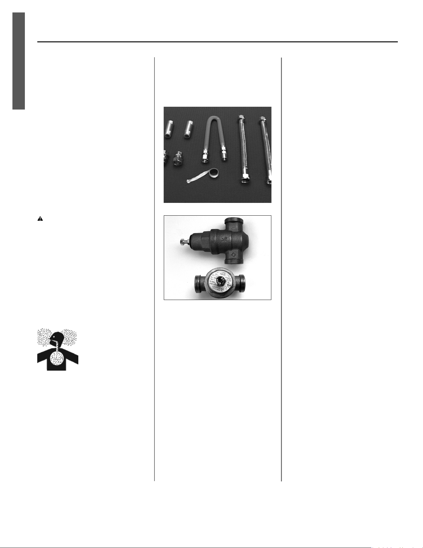
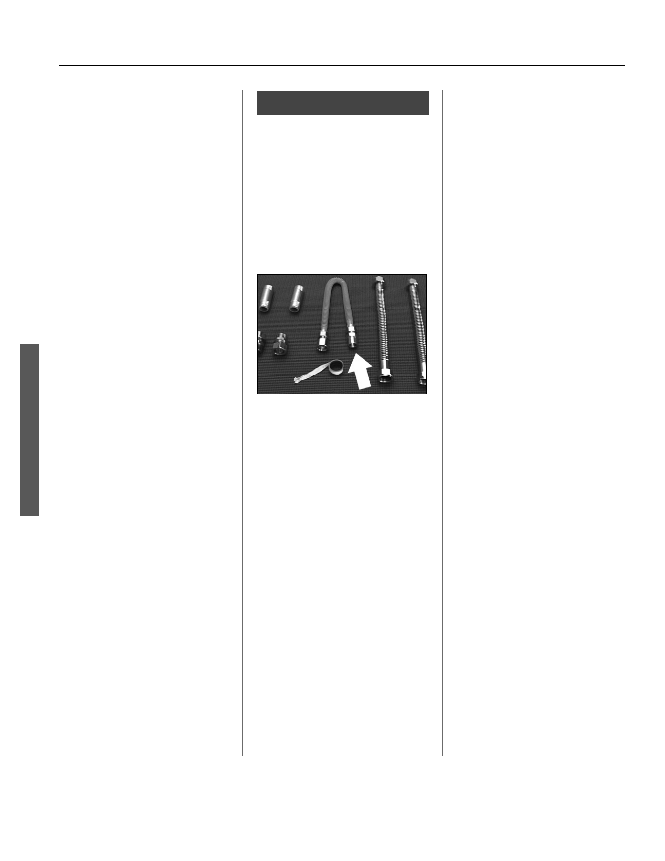
Installa on Accessories
Figure 1 - Gas Water Heater Hook-Up Kit
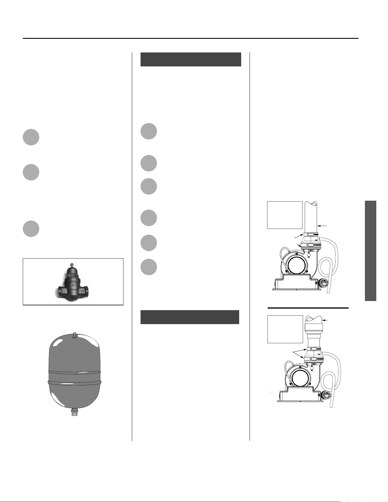
Figure 2 - Install a Pressure Reducing Valve set
to 50 to 60 PSI.
Printed on: 7/6/2023 9:40:13 AM CT
Power Vented Ultra Low Nox Gas Water Heater - Use and Care Guide • 7
GETTING STARTED
GETTING STARTED
1
Review all of the instruc ons
before you begin work. (If you
aren’t sure that you can safely
and properly do this work yourself, call
a qualifi ed person, such as a licensed
plumber, to have the work done).
Improper installa on can damage the
water heater, your home and other
property, and can present risks of
serious injury or death.
2
This water heater is design-
cer fi ed by CSA Interna onal
as a Category IV, non-direct
vented water heater which takes its
combus on air either from the installa-
on area or from air ducted to the unit
from the outside. This water heater
must be installed according to all local
and state codes or, in the absence of
local and state codes, the “Na onal
Fuel Gas Code”, ANSI Z223.1 (NFPA
54)-current edi on. This is available
from the following:
CSA America, Inc.
8501 East Pleasant Valley Road
Cleveland, OH 44131
Na onal Fire Protec on Associa on
1 Ba erymarch Park
Quincy, MA 02269
Check with local code offi cials about
codes governing this installa on. Have
your installa on inspected by a code
offi cial to ensure the installa on meets
all local codes.
NOTICE: If you lack the necessary skills
required to properly install this water
heater, or you have diffi culty follow-
ing the instruc ons, you should not
proceed but have a qualifi ed person
perform the installa on of this water
heater.
Massachuse s code requires this water
heater to be installed in accordance
with Massachuse s 248-CMR 2.00 and
248-CMR 5.00: State Plumbing Code.
Other local and state authori es may
have similar requirements or other
codes applicable to the installa on of
this water heater.
3
Before you start, be sure you
have the following tools and
supplies:
• Common plumbing tools (depend-
ing on what type of water pipes
you have).
• Thread sealant tape or pipe joint
compound approved for potable
water.
• For homes with copper pipes, and
where allowed by local codes, you
may purchase a gas water heater
hook-up kit (available from your
plumbing supplier) with compres-
sion fi ngs that don’t require
soldering. NOTE: Where allowed by
local codes.
• For homes with plas c pipe, use
threaded connectors suitable for
the specifi c type of plas c pipe
used: CPVC or PEX (cross-linked
polyethylene). Do not use PVC pipe.
• Non-corrosive gas leak detec on
solu on made from hand dish-
washing soap mixed with water (1
part soap to 15 parts water) or chil-
dren’s soap bubbles and a small,
so -bristled brush.
• An appliance dolly or hand truck to
move the water heater.
Recommended Accessories:
• A metal drain pan.
• Automa c water leak detec on
and shut-off device.
• Pressure Reducing Valve.
• Thermal Expansion Tank.
• Thermosta c Mixing Valves at each
point-of-use.
• Fuel gas and carbon monoxide
detector.
Combus on and
Ven la on Air Supply
Before installing the water heater, you
must determine the amount of air
needed to supply this water heater
and any other gas appliances in the
same area and provide adequate air for
combus on and ven la on. Consult a
qualifi ed person if you’re unsure of the
proper way to supply air to your water
heater.
WARNING! This gas water heater
requires an adequate source of clean
air for combus on and ven la on.
Without suffi cient air, your water
heater may emit excessive and
abnormal amounts of carbon
monoxide.
Before beginning:
Calculate total BTU/HR ra ng of all ap-
pliances.
To calculate the combus on air and
ven la on required, add up the total
BTU/HR ra ngs of all gas burning ap-
pliances (e.g., water heaters, furnaces,
clothes dryers) in the same area.
Your water heater’s BTU/HR ra ng is on
the ra ng plate, located next to the gas
control valve/thermostat. The BTU/HR
ra ngs should be on the other appli-
ances’ ra ng plates. If you have trouble
determining the BTU/HR ra ngs,
contact the manufacturer or have a
qualifi ed person determine the ven la-
on requirements. NOTICE: If you are
replacing your old water heater with
one that has a higher BTU/HR ra ng,
the amount of ven la on required may
be greater.
Printed on: 7/6/2023 9:40:13 AM CT
8 • Power Vented Ultra Low Nox Gas Water Heater - Use and Care Guide
GETTING STARTED
GETTING STARTED
Example:
Gas Burning Appliance BTU/HR Ra ng
Gas Water Heater 40,000
Furnace 75,000
Dryer 20,000
Total 135,000
Your Appliances:
Gas Burning Appliance BTU/HR Ra ng
Gas Water Heater
Total
Table 2 provides examples of minimum
square footage (area) required for
various BTU/HR totals. Areas used for
storage or which contain large objects
containing less air than is assumed for
the room sizes in Table 2 – see Op on
A for more specifi c calcula ons.
Op on A: Installa on without
outside ven la on (not recom-
mended)
Ven la on with outside air is recom-
mended for all installa ons. Even if
the water heater is installed in a large,
open room inside the house, outdoor
air is usually needed because modern
homes are very ghtly sealed and
o en do not supply enough air to the
water heater. However, when installed
in a large indoor space, it may be pos-
sible to provide enough air without
outside ven la on. If you are unsure if
your installa on loca on has enough
ven la on, contact your local gas
u lity company or code offi cials for a
safety inspec on.
The following instruc ons will help de-
termine if it may be possible to install
without outside ven la on. If there is
not enough ven la on, you will need
to ven late with outside air.
Check for Chemicals:
Air for combus on and ven la on
must be clean and free of corrosive or
acid-forming chemicals such as sulfur,
fl uorine, and chlorine. Ven la on with
outside air will reduce these chemicals,
but it may not completely eliminate
them. Failure due to corrosive chemi-
cals is not covered by the warranty.
Examples of loca ons that require
outside air due to chemicals include:
• Beauty salons
• Photo processing labs
• Indoor pools
• Laundry, hobby, or cra rooms
• Chemical storage areas
Products such as aerosol sprays, de-
tergents, bleaches, cleaning solvents,
gasoline, air fresheners, paint and
varnish removers, and refrigerants
should not be stored or used near the
water heater.
A1: Calculate the air volume of
the room
Air requirements depend on the size of
the room.
Floor Area (Square feet) X Ceiling
Height (feet) = Room Volume (cubic
feet)
If there are large objects in the room
(e.g., refrigerator, furnace, car), sub-
tract their volume from the volume of
the room to get a be er es mate of
the air available.
Room Volume – Object Volume = Air
Volume
Table 2
BTU/HR Minimum Square Typical Room
Input Feet with 8’ Ceiling with 8’ Ceiling
30,000 188 9 x 21
45,000 281 14 x 20
60,000 375 15 x 25
75,000 469 15 x 31
90,000 563 20 x 28
105,000 657 20 x 33
120,000 750 25 x 30
135,000 844 28 x 30
Printed on: 7/6/2023 9:40:13 AM CT
Power Vented Ultra Low Nox Gas Water Heater - Use and Care Guide • 9
GETTING STARTED
GETTING STARTED
A2: Calculate required air volume
A water heater installed in an unconfi ned
a c or garage requires that the space
be at least 50 cubic feet per 1,000 BTU/
HR of the total input for all gas burning
appliances in the same area.
[Total BTU/HR/1000] x 50 = Cubic feet
of air required.
Example:
(135,000 / 1000) x 50 = 6,750
If the air volume of the room is less
than the required air volume, you must
provide two permanent outside air
openings that draw in suffi cient air. Use
Op on B.
If the air volume of the room is greater
than the required air volume, it may
be possible to install the water heater
without outside ven la on.
A3: Verify that combus on ven-
la on is adequate
Because modern homes are o en well-
sealed to prevent dra s, even a large
room may not provide enough combus-
on air without ven la on. However,
your power-vented system could iden-
fy inadequate ven la on by triggering
an error code (See page 32) . S ll,
you must follow all instruc ons in this
sec on to ensure adequate ven la o n .
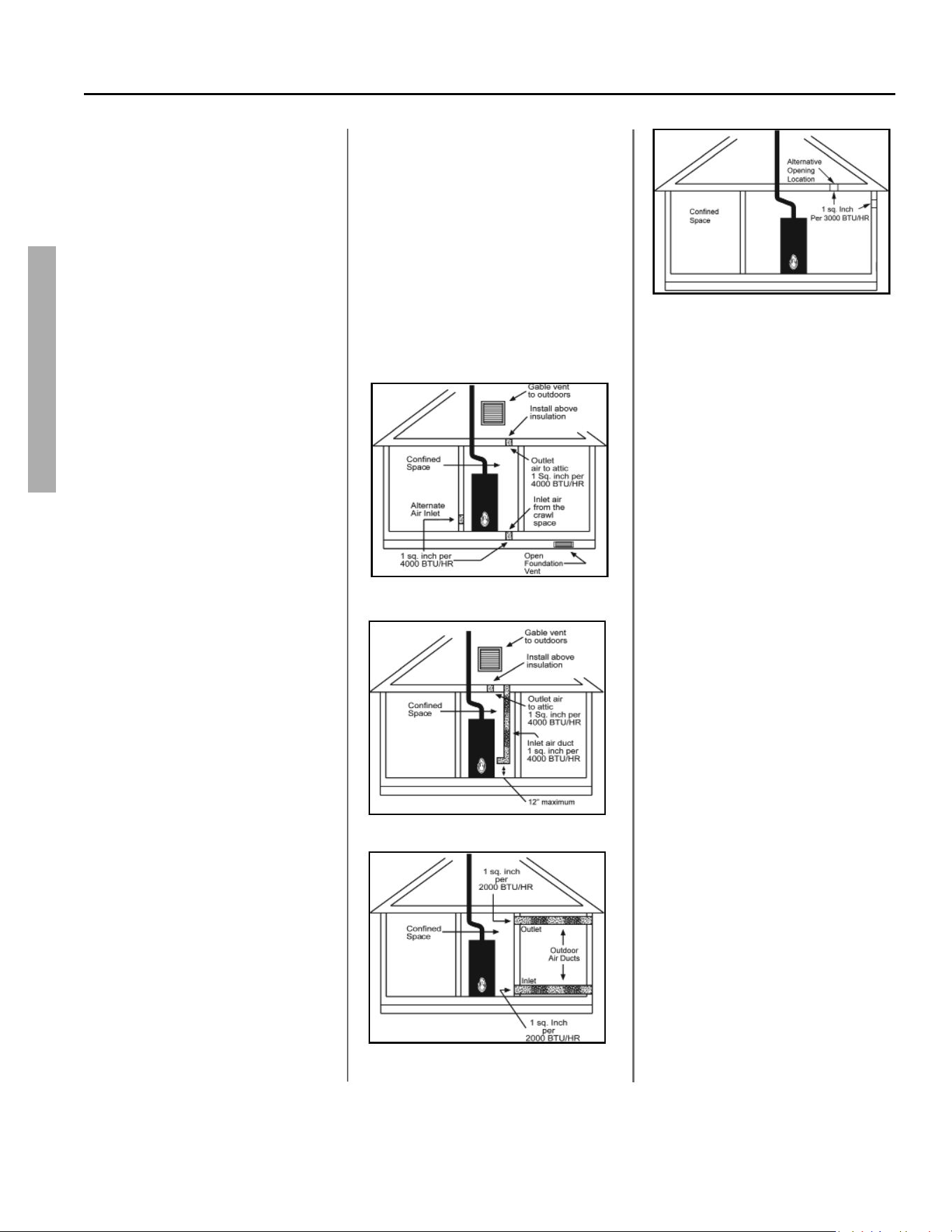
Op on B: Install with outside
ven la on
Ven la on with outside air is recom-
mended, and, for most installa ons, is
needed. There may be exis ng ven la-
on that is adequate, or you may need
to add more ven la on.
Supplying outside air typically requires
two openings. One opening must be
within 12 inches from the fl oor and
the second opening must be within 12
inches from the ceiling. Although a single
opening is not preferred, you may use a
single opening to outside air if the mini-
mum free area is sized according to Table
3. Two openings must be used when
ven la ng with air from another room.
The outside air can be taken from a
crawl space or a c open to the out-
doors and adequately ven lated. You
may use ver cal or horizontal ducts.
B2: Determine type of ven la on
There are several types of ven la on
that can be used :
1. Direct to outdoors
2. Ver cal ducts
3. Horizontal ducts
4. Single opening (not recom-
mended; must be at least 100
square inches. Not appropriate
for confi ned spaces smaller than
50 cubic feet per 1,000 BTU/HR as
calculated in sec on A or when
ge ng air from another room.)
5. From a larger room inside the
house (not recommended – refer
to sec on A above to determine if
the combined volume of the rooms
may be adequate).
B3: Determine minimum free
area required for each vent
opening
The size of the vent openings depends
on the total BTU/HR ra ng of all appli-
ances in the space (use your calcula on
from “Before beginning”) and the type
of vent used. Table 3 provides the mini-
mum free area for each vent opening
depending on the type of ven la on.
B4: Calculate minimum size of
vent openings and ducts
The vent cross-sec onal area needed to
provide the free area depends on the
covering on the vent openings. Typical
vents use louvers or grilles to protect
the opening. The louver or grill itself
blocks some of the free area, so the
opening may need to be larger to meet
the minimum free area requirements.
Use the following formula to calculate
the required cross-sec onal area:
Table 3
Minimum Free Area of Permanent Openings for Ven la on and Combus on Air
Supply – All Air from Outdoors Only.
Based on the total BTU/HR input ra ng for all gas burning appliances within a
confi ned space.
Opening Source Minimum Free Area
Per Opening (sq. in.)
*Direct to outdoors 1 sq. in. per 4,000 BTU/HR (see fi gure on page 10)
Ver cal ducts 1 sq. in. per 4,000 BTU/HR (see fi gure on page 10)
Horizontal ducts 1 sq. in. per 2,000 BTU/HR (see fi gure on page 10)
Single Opening 1 sq. in. per 3,000 BTU/HR (see fi gure on page 10)
*These openings connect directly with the outdoors through a ven lated a c, a
ven lated crawl space, or through an outside wall.
Printed on: 7/6/2023 9:40:13 AM CT
10 • Power Vented Ultra Low Nox Gas Water Heater - Use and Care Guide
GETTING STARTED
GETTING STARTED
Cross-sec onal area = minimum free
area required ÷ percent free area of
covering (in decimals – e.g., 60% = .6)
For example, an installa on area that
requires openings with 100 square
inches of free area would need 134
square inch openings if using metal
louvers rated at 75% free area (100 sq.
in. ÷ .75 = 134 sq. in.).
If you do not know the % free area for
your louver or grill, use the following
values:
• For wood louvers or grilles: 20%
• For metal louvers or grilles: 60%
Follow these rules to ensure that vents
and ducts provide adequate air fl ow:
• Each vent opening must be no
smaller than 100 square inches .
• Ducts must have the same cross-
sec onal area as free area of the
opening.
• All dimensions for rectangular
ducts must be no less than three
inches.
• All screens must have mesh ¼” or
larger.
• Moveable louvers must be locked
open or interconnected with the
equipment so that they open au-
toma cally during opera on.
• Keep louvers and grills clean and
free of debris or other obstruc-
ons.
B5: Check that air source is
clean and free of chemicals
Air for combus on and ven la on
must be clean and free of corrosive
or fl ammable chemicals. A failure due
to corrosive chemicals in the air is not
covered by the warranty. Combus-
on air must be free of acid-forming
chemicals such as sulfur, fl uorine, and
chlorine. Be sure that air at the vent
inlets is free of such chemicals.
B6: Verify that combus on
ven la on is adequate
Your power-vented system could trigger
an error code (page 32) if there is
insuffi cient combus on air. However,
you must also ensure that adequate
combus on air is available by following
all instruc ons in this sec on. Please
verify your calcula ons before you
proceed.
Combus on Air Supply Op ons
Figure 3 - Direct to outdoors openings
Figure 4 - Vertical duct openings
Figure 5 - Vertical duct openings
Figure 5 - Horizontal duct openings
Figure 6 - Single opening
Printed on: 7/6/2023 9:40:13 AM CT
Power Vented Ultra Low Nox Gas Water Heater - Use and Care Guide • 11
GETTING STARTED
Ven ng
WARNING!
• Carbon Monoxide Hazard. This
water heater must be supplied
with adequate air and vented to
the outdoors. The vent system
must be installed by a qualifi ed
person. Examples of a qualifi ed
person include gas technicians,
authorized gas company
personnel, and authorized service
technicians.
• Check to make sure the vent pipe
is not blocked in any way. Do not
common vent this water heater
with any other appliance. Do
not install in the same chase or
chimney with a metal or high-
temperature plastic from another
gas or fuel burning appliance.
• Failure to properly vent the water
heater can result in severe injury
or death from carbon monoxide
poisoning.
• Do not use Schedule 40 PVC
ven ng if used in areas with
ambient temperatures above
110°F.
This water heater must be properly
vented for removal of exhaust gases
to the outside atmosphere. Correct
installation of the vent pipe system is
mandatory for the safe and efficient
operation of this water heater and is
an important factor in the life of the
unit.
The vent pipe must be installed in
accordance with state and local codes,
or in the absence of such, the National
Fuel Gas Code, NFPA 54, ANSI Z223.1-
current edition.
To reduce the risk of carbon monoxide
poisoning, install a fuel gas and carbon
monoxide detector. Install and maintain
the detector in accordance with the
manufacturer’s instruc ons and local
codes.
Vent Pipe Material
The following plastic materials may be
used for exhaust outlet piping subject
to state and local codes.
• 2 or 3 inch Schedule 40 PVC,
CPVC, ABS, and polypropylene
• 2 or 3 inch Schedule 40 or PVC,
CPVC, ABS, and polypropylene
• DWV Pipe is acceptable
Reference Table 5 for more
information.
Use of cellular core PVC (ASTM
F891), cellular core CPVC, or Radel®
(polyphenolsulfone) in non-metallic
venting systems is prohibited.
Plastic pipe and fittings are available
through most plumbing suppliers.
Always check the marking on the pipe
to make sure you are using the correct
material. See also “Connect Vent Pipe
to Blower” on page 23.
Vent Pipe Installa on
The following guidelines should be
followed when installing the exhaust
outlet piping:
• Venting should be as direct as
possible with a minimum number
of pipe fittings.
• Vent diameter must not be
reduced unless specifically noted
in the installation instructions.
• Support all horizontal pipe runs
every four feet and all vertical
pipe runs every six feet or
according to local codes.
• Vents run through unconditioned
spaces where below freezing
temperatures are expected
should be properly insulated to
prevent freezing. For horizontal
runs, wrap the vent pipe with
self-regulating 3 or 5 watt heat
tape. The heat tape must be
U.L. listed and installed per the
manufacturer’s instructions.
• Do not connect this venting
system with an existing vent or
chimney.
• Do not common vent with the
vent pipe of any other water
heater or appliance.
The exhaust outlet piping and
termination may be installed
in one of the following type
terminations:
1.) Standard Horizontal;
2.) Vertical.
All pipe, fittings, pipe cement, primers
and procedures must conform to
American National Standard Institute
and American Society for Testing and
Materials (ANSI/ASTM) standards in
the United States. This water heater
has been design certified by CSA
International for use with the listed
plastic vent pipe material.
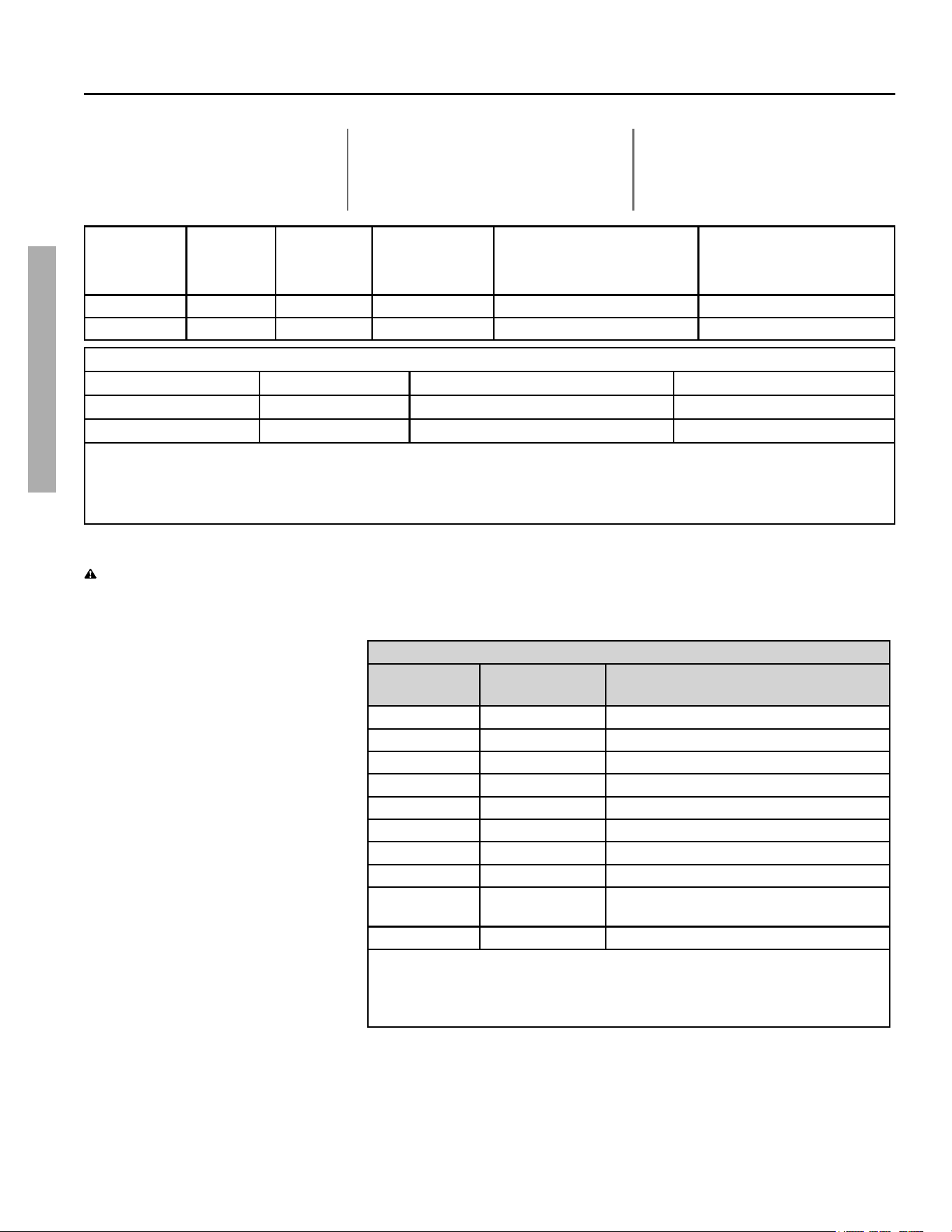
DO NOT use vent elbows in this vent
pipe installation. See “Incorrect
Fittings” in Figure 8.
All joints in the outlet piping must be
properly cemented. Size and cut all
piping before cementing.
1. Cut the pipe end square and
remove all ragged edges and
burrs. Make sure the inside of the
pipe is clean and free of cuttings
and loose dirt. Chamfer the end
and apply primer to the fitting
and pipe.
2. Using a suitable grade of pipe
cement, apply a moderate, even
coat inside the fitting. Apply a
liberal amount of cement to the
outside of the pipe to socket
depth. NOTICE: It is important to
select the proper pipe cement for
the type plastic pipe being used.
3. Assemble the parts quickly while
the cement is still wet. Twist the
pipe 1/4 turn during insertion and
hold for 30 seconds.
GETTING STARTED
Printed on: 7/6/2023 9:40:13 AM CT
12 • Power Vented Ultra Low Nox Gas Water Heater - Use and Care Guide
GETTING STARTED
GETTING STARTED
Vent Pipe Length
Size the exhaust outlet as specified
in Table 4, page 12. This table lists
the maximum allowable length in feet
of the exhaust outlet pipe as related
to the number of required elbows
and the termination. The specified
maximum lengths are for exhaust
pipe systems. Minimum pipe length is
3 feet with one elbow.
Table 4: Vent Pipe Lengths
WATER
HEATER
MODEL
HEATER
INPUT (Btu/
hr)
VENT SIZE
(Inside Diam.)
PRESSURE
SWITCH
SETTING
MAX. EQUIVALENT VENT
LENGTH
MIN. EQUIVALENT VENT
LENGTH
40 & 50 gal. 42,000 2” - 0.27 in. w.c. 50 ft. + termination elbow 7 ft. + termination elbow
40 & 50 gal. 42,000 3” - 0.27 in. w.c. 125 ft. + termination elbow 50 ft. + termination elbow
Equivalent lengths of straight pipe for various elbows using Schedule 40 PVC, CPVC and polypropylene.
Vent Pipe Size Elbow Type Short Sweep/Short Radius Long Sweep/Long Radius
2” or 3” 90° 8 ft. 5 ft.
2” or 3” 45° 4 ft. 2.5 ft.
Notes:
1. Use long radius elbows where possible. Minimum distance between 90º elbows should be 6” wherever possible.
2. Venting systems may use a maximum of five (5) 90° elbows.
3. Use proper screen termination (see Figure 8).
High Ambient Temperature
WARNING! Do not install in
environments above 140°F.
This heater requires room air to lower
the fl ue gas temperatures before the
gases pass through the vent system.
The dilu on air inlets are located on
the rear of the blower assembly.
As the room temperature rises, the
ability to lower the fl ue gases tempera-
ture lessens so special a en on to the
choice of ven ng material is required.
Establishing the ambient temperatures
where the heater and the ven ng is
installed is very important, especially
in regions with warmer climates or any
region that experiences hot summers.
Ambient condi ons between 105°F
and 140°F require that the ven ng
material be either CPVC or polypropyl-
ene. Areas that can experience high
ambient environments include closets,
alcoves, areas under staircases, a cs-
especially in metal roofed buildings,
areas with restricted air movement,
rooms with large solar gains, metal
sheds, industrial or commercial enter-
prises and ven ng systems exposed
to direct sunlight. For high tempera-
ture environments (105°F - 140°F),
obtain high limit switch upgrade Kit
#100112696 and use the higher rated
vent piping. Use of cellularcore PVC
(ASTM F891), cellular core CPVC, or
Radel® (polyphenylsulfone) in non-me-
tallic ven ng systems is prohibited.
Table 5:
Vent Pipe
Material
Pipe and fitting
nomenclature
Applicable Standard
PVC DWV ASTM D2665 or CSA B181.2
PVC Sch 40 ASTM D1785 or CSA B137.3
PVC SDR series ASTM D2241 or CSA B137.3
PVC BH ULC S636‡, UL 1738§
CPVC CPVC 41 ASTM D2846 or CSA B137.6
CPVC Sch 40 ASTM F441 or CSA B137.6
CPVC SDR series ASTM-F442
CPVC BH ULC S636‡, UL 1738§
ABS Sch 40 DWV
ASTM D2661§, CSA B181.1§ or ULC
S636‡
Polypropylene n/a ULC S636‡, UL 1738§
‡ Applicable to Canada only.
§ Applicable to the United States only.
Note: Use of cellular core PVC (ASTM F891), cellular core CPVC, or
Radel®(polyphenysulfone) in non-metallic venting systems is prohibited.
Printed on: 7/6/2023 9:40:13 AM CT

Power Vented Ultra Low Nox Gas Water Heater - Use and Care Guide • 13
GETTING STARTED
GETTING STARTED
Table 6:
PVC pipe
materials (solid
pipe)
DWV ASTM-D2665
Schedule 40
ASTM-D1785, SDR
Series ASTM-D2241
CPVC pipe
materials
CPVC 41
ASTM-D2846
Schedule 40
ASTM-F441
SDR Series
ASTM-F442,
ABS pipe
materials
DWV ASTM-D2661
Schedule 40
Polypropylene
vent system
UL-1738
Note: If local codes require venting
to be marked suitable for use as gas
venting, type BH venting may be used.
The fittings, other than the
Termination should be equivalent to:
Table 7:
PVC pipe
PVC DWV ASTM
D-2665
CPVC pipe CPVC ASTM F-438
ABS pipe
ABS ASTM
D-2661/3311
Polypropylene
vent system
UL-1738
If CPVC or ABS pipe and fittings are
used, the proper cement must be
used for all joints, including joining the
pipe to Termination (PVC Material).
If local codes do not allow the use of
the PVC termination when a material
other than PVC is used for venting, an
equivalent fitting of that material may
be substituted if the screen in the PVC
terminal is removed and inserted into
the new fitting.
This water heater is supplied with
the applicable vent screens. A 90°
termination elbow is optional.
ASTM D-2564 Grade Cement should
be used on PVC Materials and
ASTM F-493 Grade Cement on CPVC
Materials.
Note: Polypropylene vent systems
require separate adaptor, termination,
and elbows (field supplied). It is
recommended to use InnoFlue®
SW Residential products from
Centrotherm (www.centrotherm.
us.com).
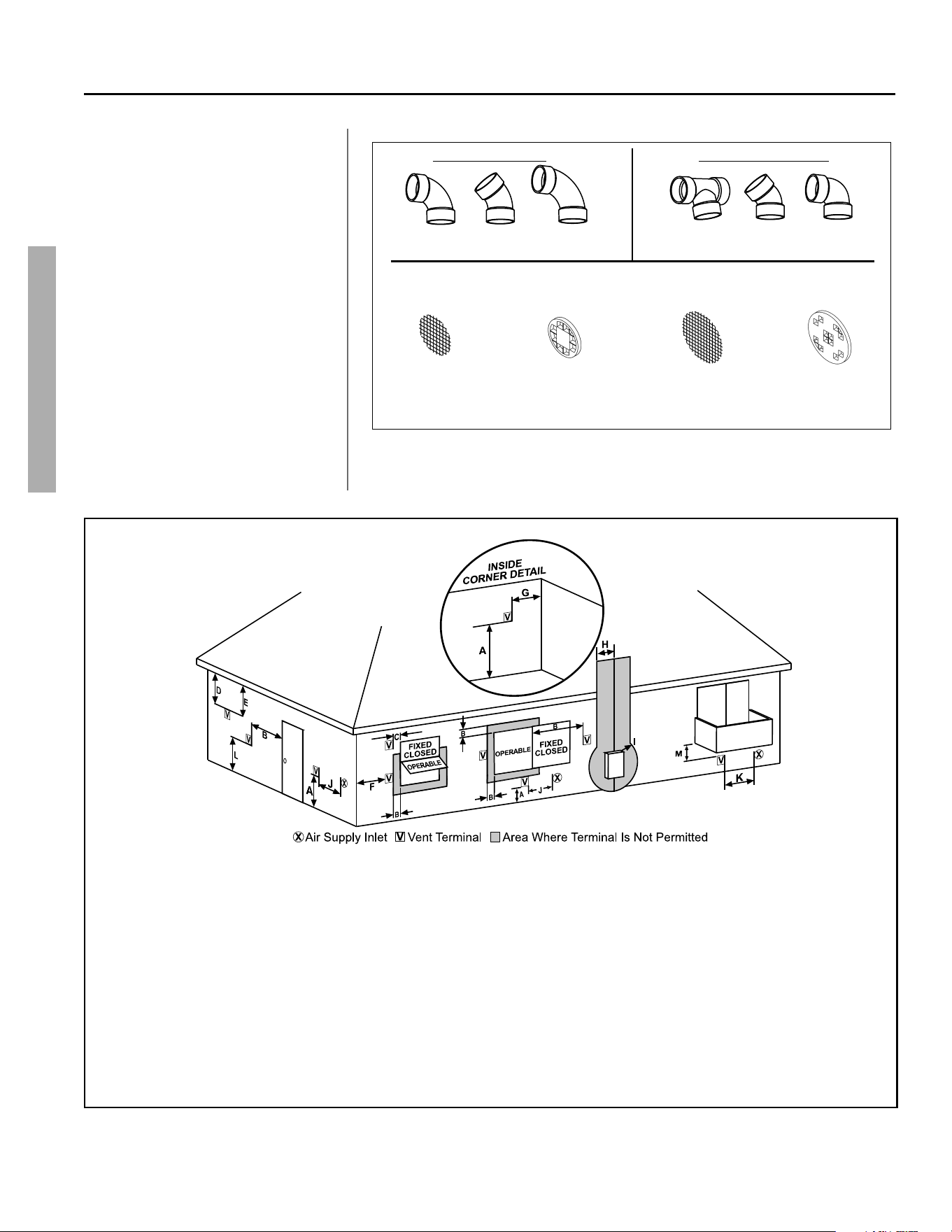
Vent Termina ons
The exhaust outlet must be installed
with the minimum clearances shown
in Figure 9.
In addition to maintaining the
minimum clearances, the vent should
terminate according to the following
guidelines:
1. Do not expose any reducers or
bushings to outdoor ambient
temperatures.
2. The vent for this appliance shall
not terminate:
• Over public walkways;
• Near soffit vents or crawl
space vents or other areas
where condensate or vapor
could create a nuisance,
hazard, or cause property
damage;
• Where condensate vapor
could cause damage or
could be detrimental to the
operation of regulators, relief
valves, or other equipment;
• Where condensate may
cause hazardous frost or ice
accumulations on adjacent
property surfaces;
• Where children or animals
could block pipes;
• Too close to shrubs or bushes.
3. Caulk all cracks, seams and joints
within 6 feet horizontally above
and below the vent.
Ver cal Termina on
The vertical exhaust outlet requires a
return bend or two medium or long
sweep radius 90° elbows to keep the
exhaust outlet downward and prevent
entry of rain. Do not include these
elbows when calculating the maximum
allowable vent pipe because they have
already been considered in the vent
tables. The vertical exhaust outlet
termination is a 2 inch or 3 inch pipe
which must be at least 12 inches
above the roof line or anticipated
snow levels. See Figure 7. Follow all
applicable code requirements.
VĞƌƟĐĂů vent tĞƌŵŝŶĂƟŽŶ
ŶƟĐŝƉĂƚĞĚ
^ŶŽǁ>ĞǀĞů
12” Min.
12” Min.
džŚĂƵƐƚ
Air
KƵƚůĞƚ
ZŽŽĨ
^ƚĂŶĚĂƌĚ,ŽƌŝnjŽŶƚĂůdĞƌŵŝŶĂƟŽŶ
ϭϮDŝŶĂďŽǀĞŐƌĂĚĞŽƌ
ĂŶƟĐŝƉĂƚĞĚƐŶŽǁůĞǀĞů
KƵƚƐŝĚĞtĂůů
sĞŶƚWŝƉĞ
Vent
dĞƌŵŝŶĂů
sĞŶƚƉŝƉĞŵƵƐƚƐůŽƉĞ
ĚŽǁŶǁĂƌĚƚŽǁĂƌĚǁĂůů
ϭϴƉĞƌϱŌŽǁŶǁĂƌĚ
ƐůŽƉĞĂƐƐŝƐƚƐĐŽŶĚĞŶƐĂƚĞ
ĚƌĂŝŶĂŐĞ
Figure 7 - Vent Terminations
Printed on: 7/6/2023 9:40:13 AM CT
GETTING STARTED
14 • Power Vented Ultra Low Nox Gas Water Heater - Use and Care Guide
A. 12 in (30 cm) min. clearance above grade, veranda,
porch, deck, balcony, or maximum anticipated snow
level.
B. Clearance to window or door that may be opened:
4 ft (1.2 m) below or to side of opening; 1 ft (300 mm)
above opening.
C. Clearance to permanently closed window.**
D. Vertical clearance to ventilated soffit located above the
terminal within a horizontal distance of 2 feet (61 cm)
from the center line of the terminal.**
E. Clearance to unventilated soffit.**
F. Clearance to outside corner. **
**Clearance in accordance with local installation codes and the requirements of the gas supplier.
US Installations
G. Clearance to inside corner.**
H. Clearance to each side of center line extended above meter/
regulator assembly.**
I. Clearance to regulator vent outlet.**
J. 12 in (300 mm) clearance above or 4 ft (1.2 m) clearance
below or to the side of non-mechanical air supply inlet to
building or the combustion air inlet to any other appliance.
K. Clearance to a mechanical air supply inlet: 3 ft (91 cm) above
if within 10 ft (3 m) horizontally.
L. Clearance above paved sidewalk or paved driveway located
on public property: 7 ft (2.13 m).**
M. Clearance under veranda, porch, deck, or balcony.**
Figure 9 - Minimum Termination Clearance for Outlet Vent
Standard Horizontal Termina on
The standard horizontal exhaust
outlet termination is a 2 inch or 3
inch pipe which terminates at least
12 inches above grade or anticipated
snow levels. To prevent potential
condensate from collecting in the
venting system, slope the vent at a
downward pitch of 1/8” per 5 ft. away
from the water heater.
Install the correct size coupling at
the outside wall on the exhaust to
prevent the termination from being
pushed inward. Follow all applicable
code requirements.
GETTING STARTED
INCORRECT FITTINGS
90° Vent
Elbow
45° Vent
Elbow
Tee Connector
CORRECT FITTINGS
90° Medium
Sweep Elbow
45° Sweep
Elbow
90° Long
Sweep Elbow
VENT LENGTH
GREATER THAN 20
EQUIVALENT FT.
VENT PIPE SCREENS FOR HEATERS WITH RATED INPUTS OF 50K BTU/HR OR LESS
2” VENTING (LONG)
VENT LENGTH
LESS THAN 20
EQUIVALENT FT.
2” VENTING (SHORT)
VENT LENGTH
GREATER THAN 50
EQUIVALENT FT.
3” VENTING
VENT LENGTH
LESS THAN 50
EQUIVALENT FT.
3” VENTING
NOTE: VENT SCREENS ARE SUPPLIED WITH THE WATER HEATER.
Figure 8 - Vent Termination Fittings
Printed on: 7/6/2023 9:40:13 AM CT
Power Vented Ultra Low Nox Gas Water Heater - Use and Care Guide • 15
GETTING STARTED
GETTING STARTED
Gas Piping
Gas piping must be installed according
to local and state codes or, in the ab-
sence of local and state codes, the “Na-
onal Fuel Gas Code”, ANSI Z223.1(NFPA
54)-current edi on.
NOTICE: When installing gas piping,
apply pipe joint compound or thread
sealant tape approved for fuel gases.
Manual gas
shut-oī valve
Sediment Trap
Check with local
ƵƟůŝƚLJĨŽƌ
minimum height
Ground
Joint
Union
3” Minimum
Figure 10 - Gas Piping
1. Install a readily accessible manual
shut-off valve in the gas supply line
as recommended by the local u lity.
Know the loca on of this valve and
how to turn off the gas to this unit.
2. Install a Sediment Trap as shown in
the Gas Piping fi gure (Figure 10).
The Sediment Trap must be no less
than three inches long for the ac-
cumula on of dirt, foreign material,
and water droplets.
3. Install a ground joint union between
the gas control valve and the manual
gas shut-off valve. This is to allow
easy removal of the gas control
valve.
4. Turn the gas supply on and check
for leaks. Use a small, so -bristled
brush to apply a hand dishwashing
soap and water mixture (1 part soap
to 15 parts water) or children’s soap
bubbles to all connec on points
of the gas piping. Saturate all the
connec ons and check for gas leaks
(which will appear as small bubbles).
If any leaks are detected, ghten
the appropriate connec on(s) and
re-check.
Gas Pressure
NOTICE: When tes ng gas pipes with
a test pressure of more than ½ psi (3.5
kPa), disconnect the gas line at the
manual shut off valve and cap the gas
line. Do not subject the water heater’s
gas control valve or manual shut off
valve to more than ½ psi (3.5 kPa) pres-
sure for any reason. If you are pressure
tes ng the gas line with test pressure of
½ psi (3.5 kPa) or less, you may isolate
the water heater from the gas line by
closing the manual shut off valve.
Solar Installa on
If this water heater is used as a solar
storage heater or as a backup for the
solar system, the water supply tempera-
tures to the water heater tank may be in
excess of 120°F. A Thermosta c Mixing
Valve or other temperature limi ng
valve must be installed in the water sup-
ply line to limit the supply temperature
to 120°F. The unit must be set to Stan-
dard Mode. (See “Opera ng Modes” on
page 28).
NOTICE: Solar water hea ng systems can
o en supply water with temperatures
exceeding 180°F and may result in water
heater malfunc on.
Printed on: 7/6/2023 9:40:13 AM CT
16 • Power Vented Ultra Low Nox Gas Water Heater - Use and Care Guide
INSTALLATION
INSTALLATION
Step 1:
✓
Verify that your
home is equipped
and up-to-date for
proper opera on
Installing a new water heater is the
perfect me to examine your home’s
plumbing system and make sure the
system is up to current code stan-
dards. There have likely been plumb-
ing code changes since the old water
heater was installed. We recommend
installing the following accessories
and any other needed changes to
bring your home up to the latest code
requirements. Upda ng your plumb-
ing system can help extend the life of
your water heater, avoid damage to
your home and property, and reduce
the risk of serious injuries or death.
Inspect your home and install any de-
vices you need to comply with current
codes and assure that your new water
heater performs at its best. Check
with your local plumbing offi cial for
more informa on.
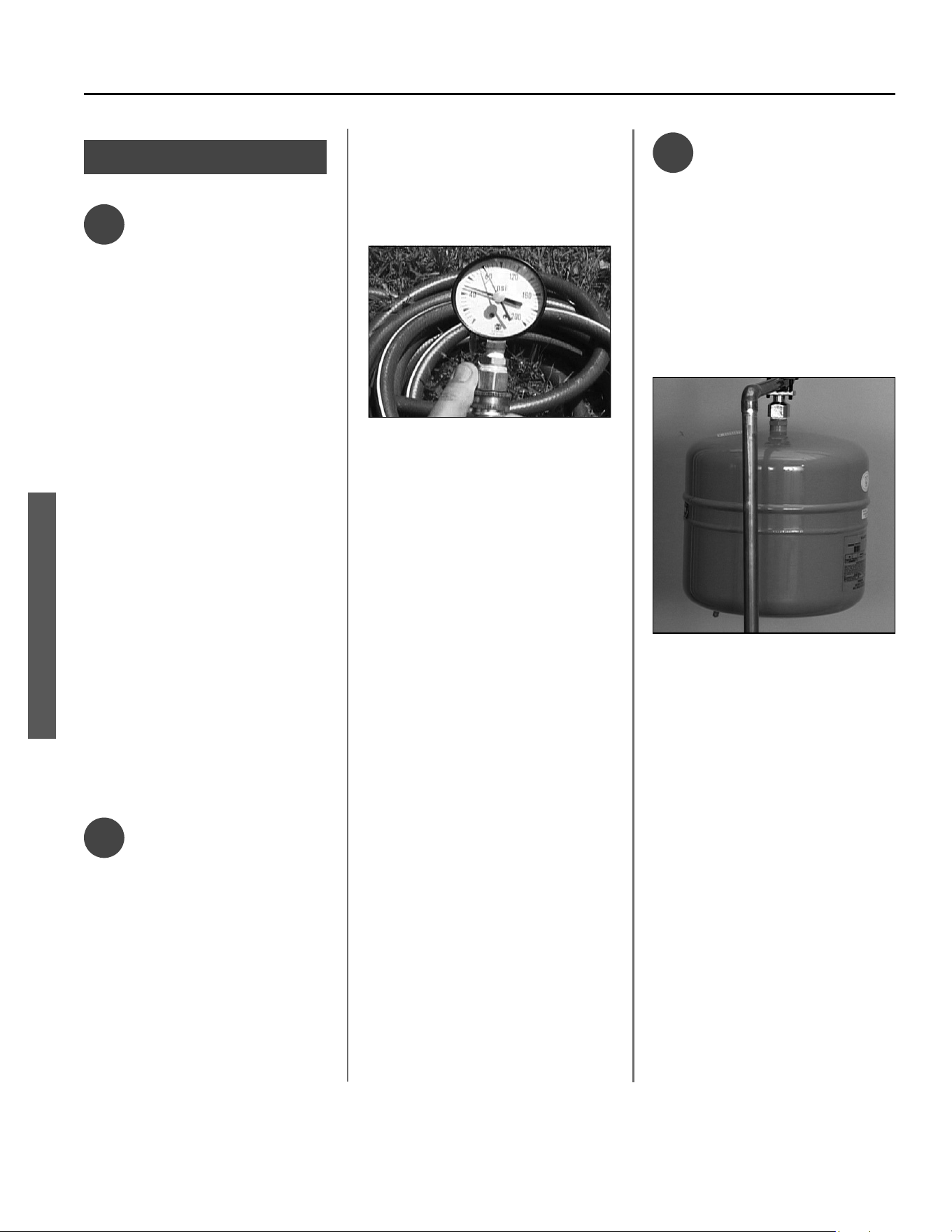
✓
Water pressure
Most codes allow a maximum
incoming water pressure of 80 psi
(we recommend a working pressure
no higher than 50-60 psi). Check your
home’s water pressure with a pressure
gauge and adjust if necessary. High
water pressure can damage the water
heater, piping, and other appliances.
HOW: Purchase an inexpensive water
pressure gauge. Connect the water
pressure gauge to an outside faucet
and measure the maximum water
pressure experienced throughout a
24-hour period (highest water pres-
sures o en occur at night).
Figure 11 - Use a Water Pressure Gauge to make
sure your home’s water pressure is not too
high.
To adjust your home’s water pressure:
Locate your home’s Pressure Reduc-
ing Valve (PRV) on the main incoming
(cold) water supply line and adjust the
water pressure control to between
50 and 60 psi. If your home does not
have a PRV, install one on the home’s
main water supply line and set it to
between 50 and 60 psi. Pressure Re-
ducing Valves are available from your
local plumbing supplier.
BACKGROUND: Over the years,
many u li es have increased water
supply pressures so they can serve
more homes. In some homes today,
pressures can exceed 100 psi. High
water pressures can damage water
heaters, causing premature leaks. If
you have replaced toilet valves, had
a water heater leak, or had to repair
appliances connected to the plumb-
ing system, pay par cular a en on
to your home’s water pressure. When
purchasing a PRV, make sure the PRV
has a built-in bypass.
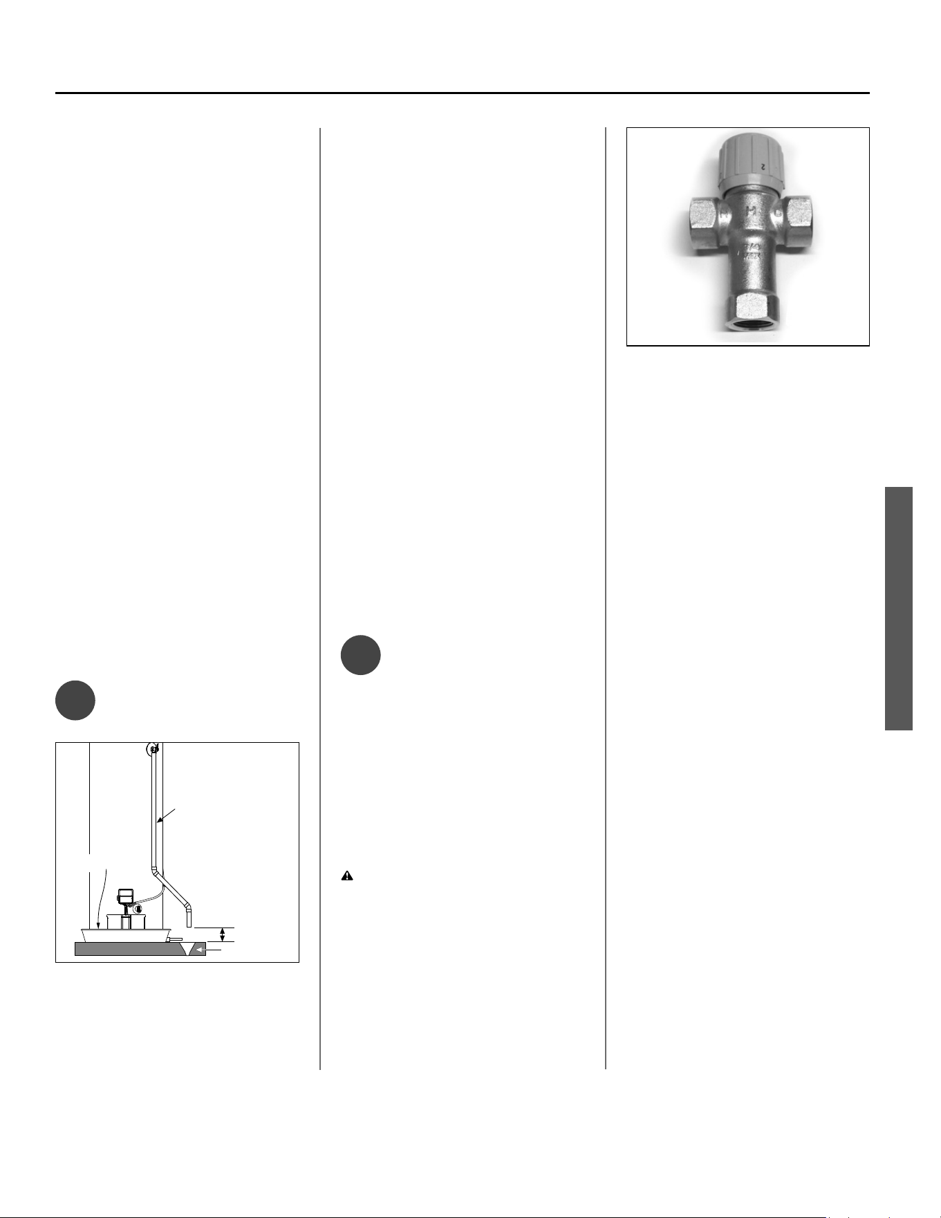
✓
Water pressure
increase caused
by thermal expansion
Verify that you have a properly sized
Thermal Expansion Tank. We recom-
mend installing an expansion tank if
your home does not have one. Plumb-
ing codes require a properly pressur-
ized, properly sized Thermal Expan-
sion Tank in almost all homes.
Figure 12 - A Thermal Expansion Tank helps
protect the home’s plumbing system from pres-
sure spikes.
HOW: Connect the Thermal Expan-
sion Tank (available from your local
plumbing supplier) to the cold water
supply line near the water heater. The
expansion tank contains a bladder and
an air charge. To work properly, the
Thermal Expansion Tank must be sized
according to the water heater’s tank
capacity and pressurized to match
the home’s incoming water pressure
before applying water pressure to the
expansion tank. Refer to the instruc-
ons provided with the Thermal
Expansion Tank for installa on details.
BACKGROUND: Water expands when
heated, and the increased volume
of water must have a place to go, or
Printed on: 7/6/2023 9:40:13 AM CT
Power Vented Ultra Low Nox Gas Water Heater - Use and Care Guide • 17
INSTALLATION
INSTALLATION
thermal expansion will cause large
increases in water pressure (despite
the use of a Pressure Reducing Valve
in the home’s main water supply line).
The Safe Drinking Water Act of 1974
requires the use of backfl ow preven-
ters and check valves to restrict water
from your home reentering the public
water system. Backfl ow preventers are
o en installed in water meters and
may not be readily visible. As a result,
most plumbing systems today are now
“closed,” and almost all homes now
need a Thermal Expansion Tank.
A Thermal Expansion Tank is a prac -
cal and inexpensive way to help avoid
damage to the water heater, washing
machine, dishwasher, ice maker, and
even toilet valves. If your toilet oc-
casionally runs for no apparent reason
(usually briefl y at night), that may be
due to thermal expansion increasing
the water pressure temporarily.
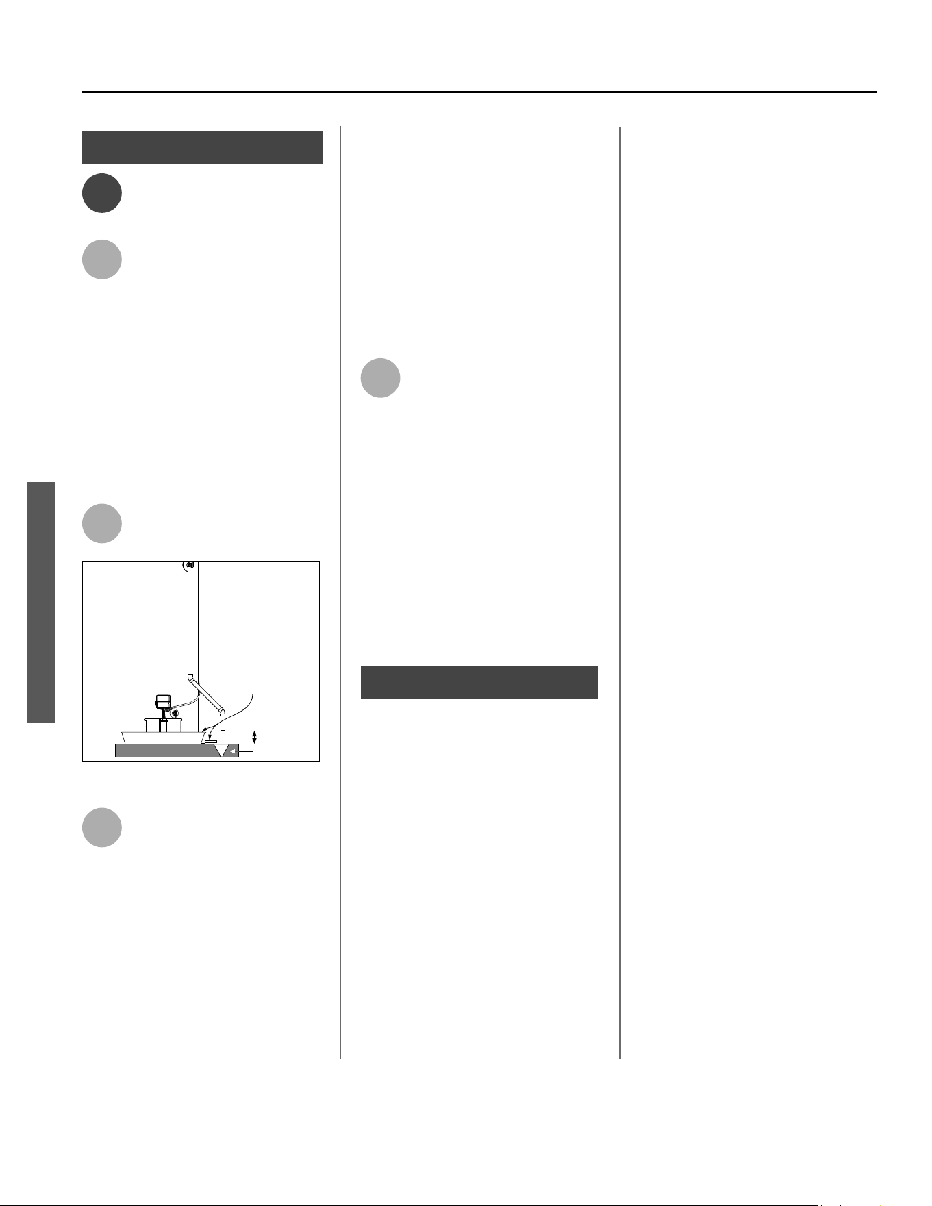
✓
Water Pipe and
Tank Leaks
Discharge line 3/4” Min.
Do not cap or plug.
6” Max.
Drain
Metal drain pan
Figure 13 - A metal drain pan piped to an ad-
equate drain can help protect flooring from leaks
and drips.
Leaks from plumbing pipes or from the
water heater itself can damage prop-
erty and could cause a fi re risk.
• Install an automa c leak detec on
and shutoff device (available from
your local plumbing supplier). These
devices can detect water leaks and
can shut off the water heater’s water
supply if a leak occurs.
• Install a metal drain pan (available
from your local plumbling supplier)
under the water heater to catch
condensa on or leaks from the pip-
ing connec ons or tank. Most codes
require, and we recommend, install-
ing the water heater in a metal drain
pan that is piped to an adequate
drain. The drain pan must be at least
two inches wider than the diameter
of the water heater. Install the drain
pan so the water level would be lim-
ited to a maximum depth of 1-3/4”.
The pan must not restrict air fl ow to
the burner.
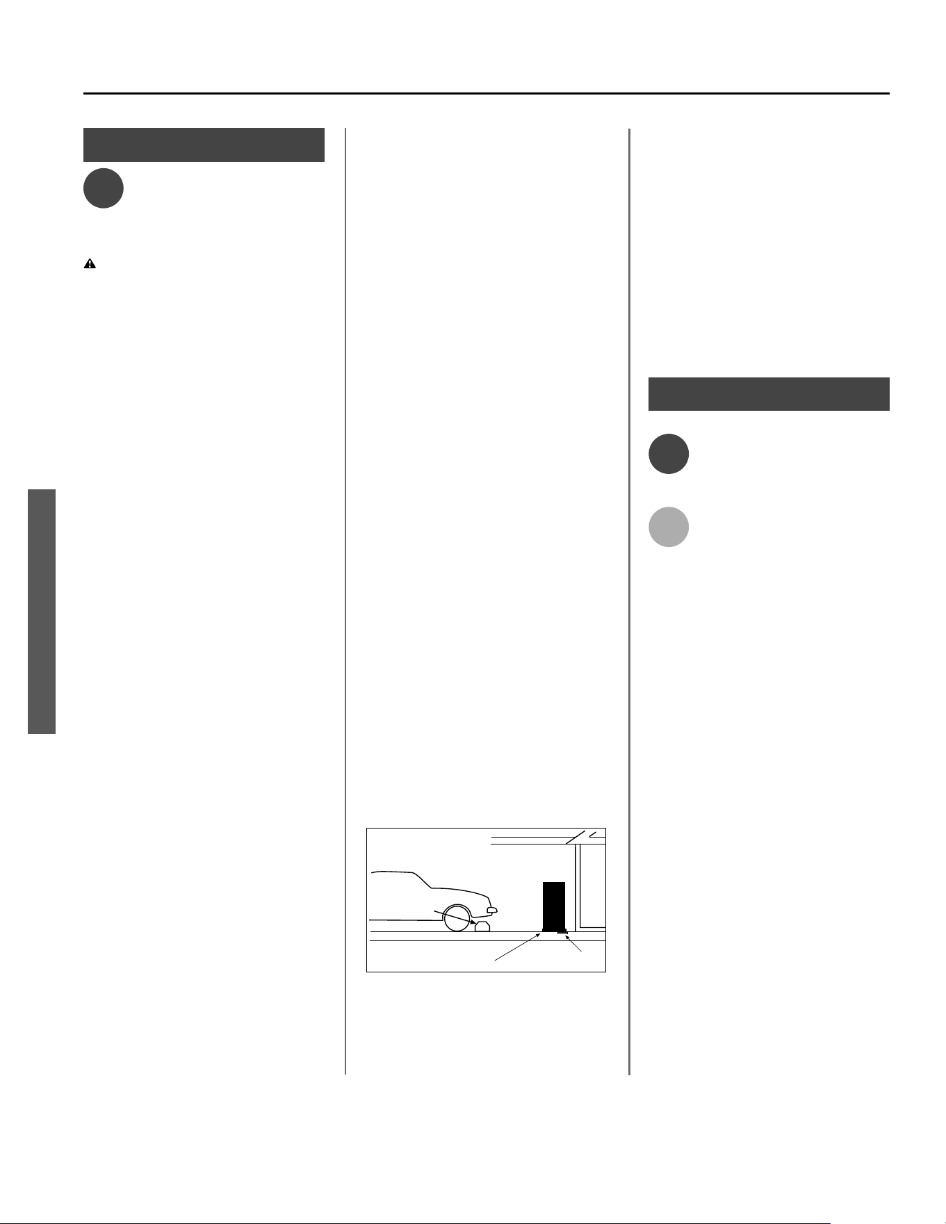
✓
Water Tempera-
ture Regula on
Install Thermosta c Mixing Valves to
regulate the temperature of the water
supplied to each point-of-use (for
example, kitchen sink, bathroom sink,
bath, shower). Install and adjust the
mixing valve according to its manufac-
turer’s instruc ons.
WARNING! Even if the water
heater’s thermostat is set to a rela-
vely low temperature, hot water can
scald. Install Thermosta c Mixing
Valves at each point-of-use to reduce
the risk of scalding.
Figure 14 - Thermostatic Mixing Valves installed
at each point-of-use can help avoid scalding
BACKGROUND: A Thermosta c Mixing
Valve, installed at each point-of-use,
mixes hot water from the water heater
with cold water to more precisely
regulate the temperature of hot water
supplied to fi xtures. If you aren’t sure
if your plumbing system is equipped
with properly installed and adjusted
Thermosta c Mixing Valves at each
point where hot water is used, contact
a qualifi ed person.
Printed on: 7/6/2023 9:40:13 AM CT
18 • Power Vented Ultra Low Nox Gas Water Heater - Use and Care Guide
INSTALLATION
INSTALLATION
Step 2:
✓
Verify that the
loca on is
appropriate
WARNING! Do not store or use
fl ammable materials, vapors, or
liquids in the same loca on where this
water heater is installed.
Before installing your water heater,
ensure that it will be located:
• Indoors in an area with adequate
air supply.
• In an area that will not freeze.
• In a metal drain pan piped to an
adequate drain.
• In an area with adequate space
(clearances) for periodic servicing
(there must be a minimum of 24
inches of front clearance).
• In an area that allows a minimum
clearance from combustible
surfaces as stated on the rating
plate. Refer to the minimum
clearances listed on the rating
plate on the water heater.
• On a fl oor that can support the
weight of a water heater full of water.
You will also want to follow these
guidelines while considering an appro-
priate loca on:
• Do not install near air-moving
devices such as exhaust fans,
ven la on systems, or clothes
dryers.
• Do not obtain ven la ng air for
the furnace/air handler from the
same space as the water heater.
Ensure that any return air ducts
near the water heater are sealed.
• If the water heater is located
in an area subject to lint, dust,
or oily vapors, at least annually
check and clean the air fi lter. See
Maintenance sec on for steps on
cleaning the air fi lter.
• Do not install in a bathroom,
bedroom, or any occupied room
normally kept closed.
• If the water heater is installed di-
rectly on carpe ng, it shall be in-
stalled on a metal or wood panel
extending beyond the full width
and depth of the water heater
by at least 3 in (76.2mm) in any
direc on. If the water heater is
installed in an alcove or closet,
the en re fl oor shall be covered
by the panel.
• If your area is prone to earth-
quakes, use special straps as
required by local building codes.
NOTICE: The state of California re-
quires bracing, anchoring, or strap-
ping the water heater to avoid its
moving during an earthquake. Contact
local u li es for code requirements in
your area, visit h p://www.dsa.dgs.
ca.gov, or call 1-916-445-8100 and
request instruc ons. Other loca ons
may have similar requirements. Check
with your local and state authori es.
• Do not install in a loca on prone
to physical damage by vehicles,
fl ooding, or other risks.
Vehicle
Stop
Drain
Drain
Pan
Figure 15 - In a garage, install a vehicle stop to
avoid water heater damage.
• Avoid loca ons such as a cs, up-
per fl oors, or where a leak might
damage the structure or furnish-
ings. Due to the normal corrosive
ac on of water, the tank will
eventually leak. To minimize prop-
erty damage from leaks, inspect
and maintain your water heater
in accordance with this manual’s
instruc ons. Install a metal drain
pan under the water heater piped
to an adequate drain. Inspect the
drain pan, pipes, and surrounding
area regularly and fi x any leaks
found.
Step 3:
✓
Removing the old
water heater
1
Read each installa on step and
decide if you have the neces-
sary skills to install the water
heater. Only proceed if you are comfort-
able you can safely perform the work. If
you are not sure, have a qualifi ed person
perform the installa on.
ConƟ nued on the next page...
Printed on: 7/6/2023 9:40:13 AM CT
Power Vented Ultra Low Nox Gas Water Heater - Use and Care Guide • 19
INSTALLATION
INSTALLATION
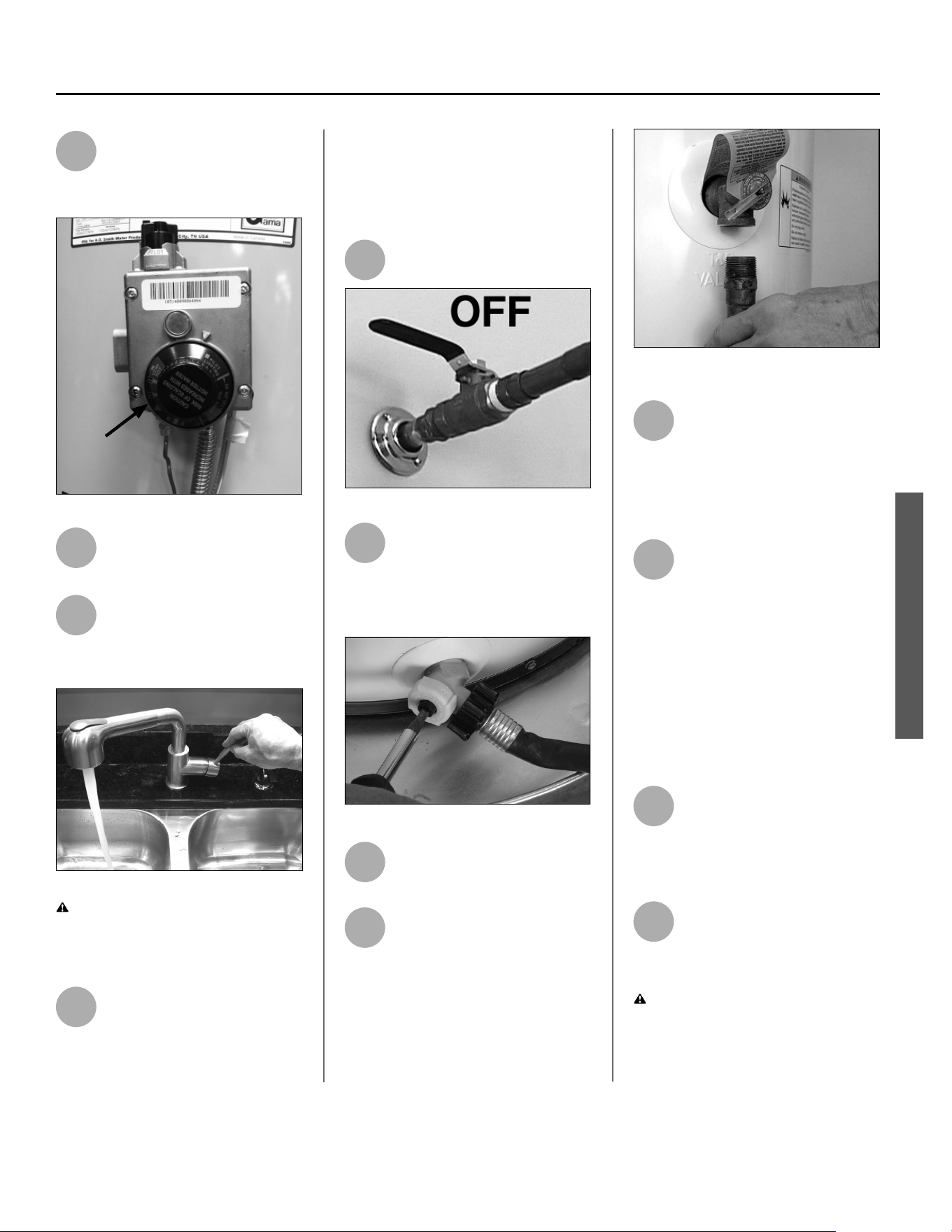
2
On the old water heater, turn
the control knob on the gas
control valve to the
OFF posi on.
Gas
control
knob
Figure 16 - Turn gas control/temperature knob OFF.
3
Turn the manual gas valve for
the water heater’s supply line
OFF.
4
Open a hot water faucet and
let the hot water run un l it is
cool (This may take 10 min
utes or longer).
Figure 17 - Let the hot water run until it is cool.
WARNING! Be sure the water runs
cool before draining the tank to reduce
the risk of scalding.
5
Connect a garden hose to the
drain valve and place the
other end of the hose in a
drain, outside, or in buckets. (Sedi-
ment in the bo om of the tank may
clog the valve and prevent it from
draining. If you can’t get the tank to
drain, contact a qualifi ed person.)
6
Turn the cold water supply
valve OFF.
Figure 18 - Cold water supply in off position.
7
Using a standard fl at-blade
screwdriver, open the drain
valve. Sediment build up in
the bo om of the water heater may
hinder or prevent draining.
Figure 19 - Draining the old water heater.
8
Also open a hot water faucet
to help the water in the tank
drain faster.
9
When the tank is empty,
disconnect the Temperature &
Pressure (T&P) Relief Valve
discharge pipe. You may be able to
reuse the discharge pipe, but do not
reuse the old T&P Relief Valve. A new
T&P Relief Valve comes with your new
water heater.
Figure 20 - Removing the T&P Relief Valve
discharge pipe.
10
Allow the ven ng system to
cool. Once it is cooled,
disconnect the vent pipe from
the water heater. You may need to
support the vent pipe un l the new
water heater is in place.
11
Disconnect the water pipes.
Many water pipes are con-
nected by a threaded union
which can be disconnected with
wrenches. If you must cut the water
pipes, cut the pipes close to the water
heater’s inlet and outlet connec ons,
leaving the water pipes as long as
possible. If necessary, you can make
them shorter later when you install the
new water heater.
12
Confi rm the manual gas valve
for the water heater’s supply
line is turned off . Disconnect
the gas line from the water heater’s
gas control valve and cap it.
13
Remove the old water heater.
Use an appliance dolly or
hand truck to move the water
heater.
WARNING! Use two or more people
to remove or install a water heater.
Failure to do so can result in back or
other injury.
Printed on: 7/6/2023 9:40:13 AM CT
20 • Power Vented Ultra Low Nox Gas Water Heater - Use and Care Guide
INSTALLATION
INSTALLATION
Step 4:
✓
Installing the New
Water Heater
1
Read all instruc ons
completely before beginning. If
you are not sure you can safely
complete the installa on, seek
assistance from any of the following
sources:
• Schedule an appointment with
a qualifi ed person to install your
water heater.
• Call Technical Assistance at the tele-
phone number listed on your war-
ranty.
2
Install a metal drain pan that
is piped to an adequate drain.
6” Max.
Drain
Metal drain pan
piped to drain
Figure 21 - Metal drain pan piped to drain.
3
Set the water heater in place,
taking care not to damage the
drain pan. When installing
directly on carpet, the water heater
must be installed on a wood or metal
base that extends beyond the dimen-
sions of the water heater (width and
depth) by at least 3 inches (76.2 mm)
in any direc on. If the water heater is
installed on carpet in an alcove or
closet, the en re fl oor must be covered
by a wood or metal panel.
NOTICE: Most codes require se ng
the water heater in a metal drain pan
piped to an adequate drain. The drain
pan helps avoid property damage
which may occur from condensa on
or leaks in the piping connec ons or
tank. The drain pan must be at least
two inches wider than the diameter
of the water heater. Install the drain
pan so the water level is limited to a
maximum depth of 1-3/4”.
4
Verify that the water heater is
set in place properly. Check
that:
• There is adequate space to install
the T&P Relief Valve discharge
pipe and that it can be piped to a
separate drain (and not into the
drain pan).
• There is adequate access and
space around the water heater
for future maintenance.
• The water heater is installed ver -
cally.
Step 5:
Air Filter Inspec on
This water heater is equipped with a
base-ring air fi lter. Before proceeding
to the next step, visually check the
fi lter to ensure it is properly seated
in the base-ring. Do not operate the
water heater without the a clean air
fi lter in place.
Printed on: 7/6/2023 9:40:13 AM CT
Power Vented Ultra Low Nox Gas Water Heater - Use and Care Guide • 21
INSTALLATION
INSTALLATION
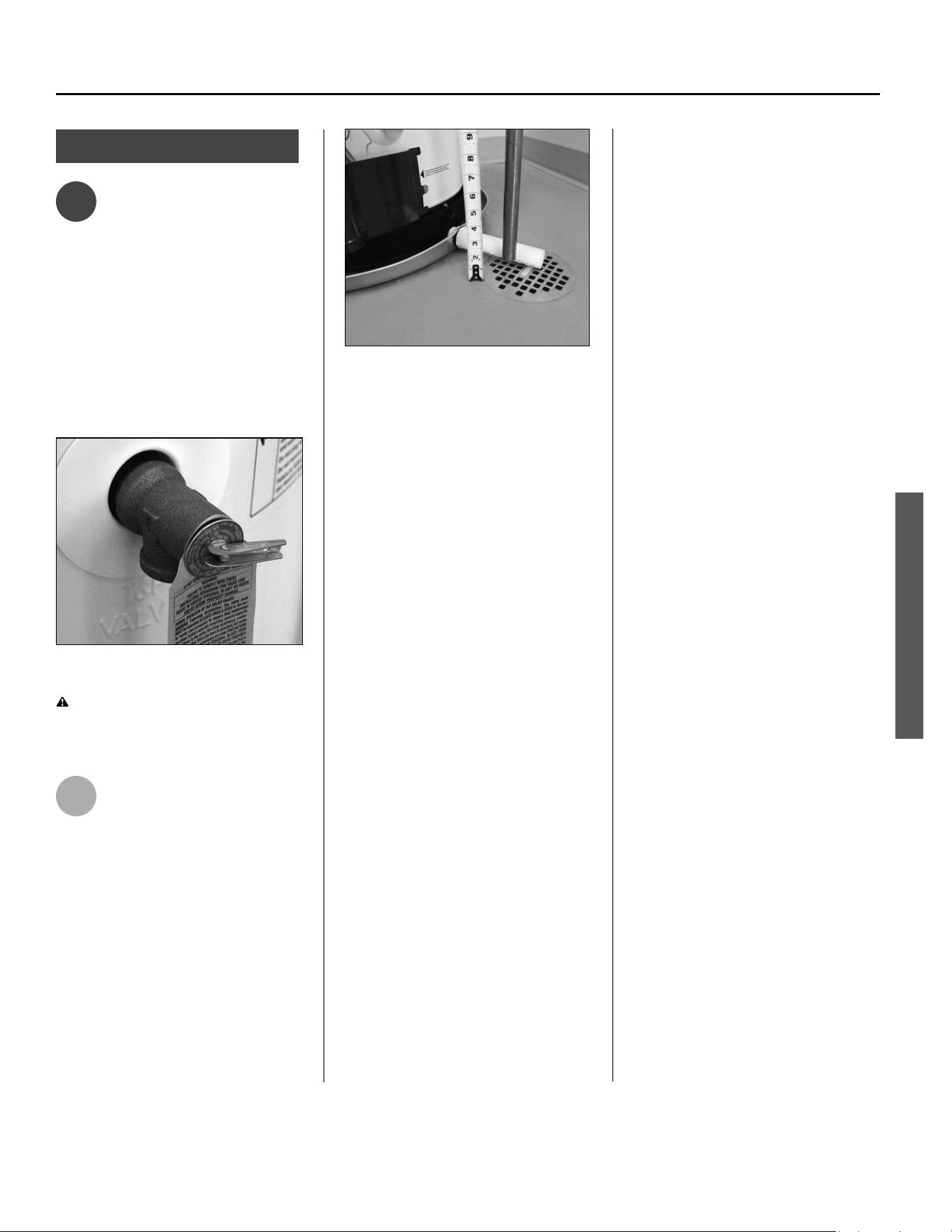
Step 6:
✓
Connect the Tem-
perature and Pres-
sure (T&P) Relief
Valve/Pipe
Most T&P Relief Valves are pre-
installed at the factory. In some cases,
they are shipped in the carton and
must be installed in the opening
marked “T&P Relief Valve” and accord-
ing to local codes.
Figure 22 - Temperature and Pressure Relief
Valve
WARNING! To avoid serious injury
or death from explosion, install a T&P
Relief Valve according to the following
instruc ons:
1
If the T&P Relief Valve was not
factory installed, install the
new T&P Relief Valve that
came with your water heater. Do not
reuse an old T&P Relief Valve.
• The discharge pipe should be at
least 3/4” inside diameter and
sloped for proper drainage. Install
it to allow complete drainage of
both the T&P Relief Valve and the
discharge pipe.
Figure 23 - Temperature and Pressure Relief
Valve Pipe
• The discharge pipe must not be
smaller than the pipe size of the
T&P Relief Valve. The pipe must
also be able to withstand 250°F
(121°C) without distor on. Use
only copper or CPVC pipe. Do not
use any other type of pipe, such as
PVC, iron, fl exible plas c pipe, or
any type of hose.
• Terminate the discharge pipe a
maximum of six inches above a
fl oor drain or outside the building.
Do not drain the discharge pipe
into the drain pan; instead pipe it
separately to an adequate drain.
In cold climates, terminate the dis-
charge pipe inside the building to
an adequate drain. Outside drains
could freeze and obstruct the
drain line—protect the discharge
pipe from freezing.
• Do not place any valve or other
restric on between the tank and
T&P Relief Valve. Do not cap,
block, plug, or insert any valve
between the T&P Relief Valve and
the end of the discharge pipe. Do
not insert or install any reducer in
the discharge pipe.
Printed on: 7/6/2023 9:40:13 AM CT
22 • Power Vented Ultra Low Nox Gas Water Heater - Use and Care Guide
INSTALLATION
INSTALLATION
Step 7:
✓
Install Shutoff and
Thermosta c
Mixing Valves
1
If one is not already installed,
install a manual shutoff valve
in the cold water line that
supplies the water heater. Install the
shutoff valve near the water heater so
that it is readily accessible. Only use a
full-fl ow ball or gate valve compa ble
with potable water.
2
Install a Thermosta c Mixing
Valve at each point-of-use
(for example, kitchen sink,
bathroom sink, bath, shower) per the
valve manufacturer’s instruc ons.
Figure 24 - Install Thermostatic Mixing Valves at
each point where hot water will be used.
WARNING! Even if the water
heater’s thermostat is set to a
rela vely low temperature, hot water
can scald. Install Thermosta c Mixing
Valves at each point-of-use to reduce
the risk of scalding.
3
For water heaters that are fed
by a solar water hea ng
system (or any other pre-
hea ng system), always install a
Thermosta c Mixing Valve or other
temperature limi ng device in the
inlet water supply line to limit water
supply inlet temperature to 120°F.
Solar water hea ng systems can
supply water with temperatures
exceeding 180°F and may result in
water heater malfunc on.
WARNING! Hot water provided by
solar hea ng systems can cause
severe burns instantly, resul ng in
severe injury or death.
Step 8:
Connect the Water
Supply
Note that all piping and components
connected to the water heater must
be suitable for use with potable water.
1
Determine the type of water
pipes in your home. Most
homes use copper water
pipes, but some use CPVC or cross-
linked polyethylene (PEX). Use fi ngs
appropriate for the type of pipe in
your home. Do not use iron or PVC
pipe.
2
Connect the cold water
supply using 3/4 inch
Na onal Pipe Thread “NPT” to the
fi ng marked “COLD”.
For ease of removing the water heater
for service or replacement, connect
the water pipes with a coupling called
a union. We recommend using a
dielectric-type union (available from
your local plumbing supplier). Dielec-
tric unions can help prevent corrosion
IF YOU HAVE COPPER PIPES:
If your home has copper water pipes,
you can solder the water pipe connec-
ons or use compression fi ngs which
don’t require soldering. Compression
fi ngs are easier to install than solder-
ing pipe. Check with local plumbing
offi cials to determine what types of
pipe materials are suitable for your
loca on. Do not use lead-based solder.
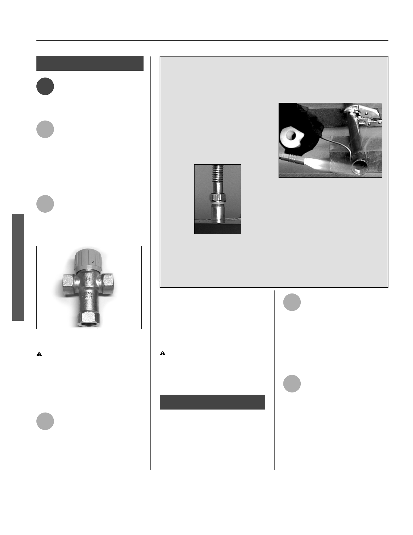
NOTICE: Do not solder pipes while
they are a ached to the water heater.
The water heater’s inlet and outlet
connec ons contain non-metallic parts
which could be damaged. The proper
way to connect the water heater to
copper water pipes is as follows:
Solder a short length of pipe (about a
foot or so) to a threaded adapter using
only 95/5 n-an mony or equivalent
solder. A ach the threaded adapters
to the water heater’s connec ons
(using thread sealant tape or pipe
joint compound). Connect the home’s
water pipes by soldering, keeping the
connec ons at the water heater cool
with wet rags.
Compression fi ngs don’t require soldering.
Printed on: 7/6/2023 9:40:13 AM CT
Power Vented Ultra Low Nox Gas Water Heater - Use and Care Guide • 23
INSTALLATION
caused by ny electric currents com-
mon in copper water pipes and can help
extend the life of the water heater.
NOTICE: Most water heater models
contain energy saving heat traps in the
inlet and outlet connec ons. Do not
remove the heat traps.
3
Connect the hot water supply
using 3/4 inch NPT to the
fi ng marked “HOT”.
4
Install insula on (or heat
tape) on the water pipes
especially if the indoor
installa on area is subject to freezing
temperatures. Insula ng the hot water
pipes can increase energy effi ciency.
5
Adjust (or install) the home’s
Pressure Reducing Valve to
50-60 psi and install a Thermal
Expansion Tank.
Figure 25 - A Pressure Reducing Valve is required
if your home’s water pressure is above 80 psi.
Figure 26 - The Thermal Expansion Tank should
be pressurized with air, using a hand pump, to
match the home’s incoming water pressure.
Step 9:
Verify Connec ons and
Completely Fill Tank
To remove air from the tank and allow
the tank to fi ll completely with water,
follow these steps:
1
Remove the aerator at the
nearest hot water faucet. This
allows debris in plumbing
system to be washed out of the pipes.
2
Turn the cold water supply
back on and fi ll the tank.
3
Open a hot water faucet and
allow the water to run un l it
fl ows with a full stream.
4
Let the water run full stream
for three minutes.
5
Close the hot water faucet
and replace the aerator.
6
Check inlet and outlet connec-
ons and water pipes for leaks.
Dry pipe connec ons so that
any drips or leaks will be apparent.
Repair any leaks. Almost all leaks occur
at connec ons and are not a tank leak.
Step 10:
Connect Vent Pipe to
Blower
Make sure your home’s ven ng system
complies with the instruc ons in this
manual and is in good condi on.
A 3”x 2” condensate drain coupler is
supplied to connect 2” venting to the
blower. The initial connection must
be made with 2” vent pipe. However,
after the initial connection, you may
use either 2” or 3” vent pipe. See
Figure 27. See also “Table 4: Vent Pipe
Lengths” on page 12
These connections must be properly
sealed to prevent the leakage of the
products of combustion into the living
area.
Before installing, clean and lightly sand
the end of the PVC/CPVC plas c vent
piping that will connect into the rubber
coupling. For polypropylene vent sys-
tems follow manufacturer’s instruc ons.
Polypropylene vent systems require
separate adaptor
NOTICE: Some installations may
require a condensate drain line. See
below.
2-Inch Vent Pipe
ŽŶŶĞĐƟŽŶ
Blower
2-Inch Vent
Pipe
Secure the vent
pipe and the
coupler to the
blower with
gear clamps.
Gear
Clamps
Condensate
Drain
Blower
Secure the vent
pipe and the
coupler to the
blower with
gear clamps.
3-Inch Vent Pipe
ŽŶŶĞĐƟŽŶ
Condensate
Drain
Gear
Clamps
3-Inch Vent
Pipe
Figure 27 - Vent Pipe/Blower Connection
INSTALLATION
Printed on: 7/6/2023 9:40:13 AM CT
24 • Power Vented Ultra Low Nox Gas Water Heater - Use and Care Guide
INSTALLATION
INSTALLATION
Condensate Drain:
Condensate forma on does not
occur in all installa ons of power
vented water heaters, but should
be drained on installa ons where it
can form in the ven ng system. The
vent pipe should be sloped upwards
away from the blower assembly, then
adequate means for draining and
disposing of the condensate needs to
be made by the installer. If installa on
condi ons cause condensa on, install
a condensate trap loop approximately
8”in diameter using 3/8” plas c hose.
Connect the hose to the built-in drain
port of the rubber coupling of the
blower assembly (see Figure 27).
Loop the hose in a ver cal posi on as
shown. The tube loop must be fi lled
with water at least half way prior to
opera ng the heater. Ensure the end
of the tube has access to a drain as
condensate will fl ow from the end.
Note: The removable cap must remain
in place if a drain hose is not installed.
Step 11:
Make Gas Connec ons
The Gas Water Heater Hook-Up Kit
(available at your local plumbing sup-
plier) includes a fl exible gas connector
with compression fi ngs to connect
the home’s gas line to the water
heater’s gas control valve. Follow the
kit’s installa on instruc ons to a ach
the fl exible gas connector.
Figure 28 - Flexible gas line connector.
Once you’ve made the gas connec-
ons, use a small, so -bristled brush
to apply a hand dishwashing soap
and water mixture or children’s soap
bubbles (1 part soap to 15 parts water)
to all connec on points of the gas line
and fl exible gas connector (if used).
Make sure to generously coat all the
connec ons and check for gas leaks
(which will appear as small bubbles).
If any leaks are detected, turn the gas
supply off , ghten the leaking connec-
on and re-check.
BEFORE LIGHTING THE WATER
HEATER...
Make sure all checklist items have
been completed.
Water Heater Loca on
✓ Installa on area free of corrosive
or fl ammable materials, liquids or
vapors.
✓ Proper clearances from combus ble
surfaces maintained and suffi cient
room to service the water heater.
✓ Not installed directly on a carpeted
fl oor.
✓ Metal drain pan installed and piped
to an adequate drain.
✓ Water heater not located near an
air moving device (fan, clothes
dryer).
✓ Not in a loca on with large
amounts of lint, dust, etc. (If so,
the air fi lter or fl ame arrestor
located on the bo om of the water
heater will need to be cleaned
more o en.)
Combus on Air Supply and
Ven la on
✓ Adequate air supply for water
heater and any other nearby gas
appliances.
If the water heater is installed in a
closet or other small, enclosed space
or within the living space of the
house, air supply openings needed.
✓ Are the openings of suffi cient size?
✓ Ductwork is the same cross-sec-
onal area as the openings?
✓ Outside air openings are preferred
and may be required in ghtly built
homes.
Printed on: 7/6/2023 9:40:13 AM CT

Power Vented Ultra Low Nox Gas Water Heater - Use and Care Guide • 25
INSTALLATION
INSTALLATION
✓ Sufficient fresh air supply for
proper water heater operation.
✓ Fresh air not taken from areas
that contain negative pressure
producing devices such as exhaust
fans, fireplaces, etc.
✓ Fresh air supply free of corrosive
elements and
flammable vapors.
✓ Fresh air openings sized correctly
with consideration given to the
blocking effect of louvers and
grilles.
✓ Ductwork is the same cross-
sectional area as the openings.
Vent Pipe System
✓ Vent pipe and fittings of approved
material.
✓ Acceptable size, length, and
number of elbows on
exhaust outlet pipe.
✓ Installed in accordance with
prevailing provisions of
local codes, or in the absence of
such, National Fuel Gas Code, NFPA
54, ANSI Z223.1-Current edition.
✓ Slope 2” & 3” horizontal piping at
a downward pitch of 1/8” per 5 ft.
away from the water heater.
✓ Not obstructed in any way.
NOTICE: Venting requirements are
listed in the “Venting” section on
page 11.
Vent Termination
Horizontal Vent Termination
✓ 12” Min. above grade/snow
level.
✓ Slope 2” & 3” horizontal
piping at a downward pitch of
1/8” per 5ft. away from the
water heater.
✓ Away from corners, other
vents, windows, etc.
Vertical Vent Termination
✓ Outlet - 12” Min. above roof/
snow level.
NOTICE: Vent termination
requirements are listed in the
“Vent Terminations” section on
page 13.
Water System Piping
✓ Temperature and pressure relief
valve properly installed with a
discharge line run to an adequate
drain and protected from freezing.
✓ Water pipes free of leaks.
✓ Water heater completely filled with
water.
✓ Thermal Expansion Tank installed
✓ Water Pressure Reducing Valve
installed and adjusted to 50-60 psi.
✓ Thermostatic Mixing Valves installed
at each point-of-use.
Gas Supply and Piping
✓ Gas type is the same as that listed
on the water heater’s rating plate.
✓ Gas line equipped with shut-off
valve.
✓ Adequate gas pipe size and
approved gas pipe material.
✓ All gas connections and fittings leak
checked and any leaks corrected.
Electrical Connections
✓ Unit connected to a 120V electrical
supply. (Do not use an extension
cord.)
✓ A dedicated circuit is preferred.
✓ Proper polarity.
✓ Electrically grounded in accordance
with local codes, or in the absence
of such, the current edition of the
National Electric Code, ANSI/NFPA
70.
See page 38 for specific
information about the electrical
system.
Printed on: 7/6/2023 9:40:13 AM CT
26 • Power Vented Ultra Low Nox Gas Water Heater - Use and Care Guide
INSTALLATION
For all side wall terminated, horizontally vented power vent, direct vent, and power direct vent gas fueled water heaters installed
in every dwelling, building or structure used in whole or in part for residential purposes, including those owned or operated by
the Commonwealth and where the side wall exhaust vent termination is less than seven (7) feet above ¿ nished grade in the
area of the venting, including but not limited to decks and porches, the following requirements shall be satis¿ ed:
INSTALLATION OF CARBON MONOXIDE DETECTORS At the time of installation of the side wall horizontal vented gas
fueled equipment, the installing plumber or gas¿ tter shall observe that a hard wired carbon monoxide detector with an alarm
and battery back-up is installed on the À oor level where the gas equipment is to be installed. In addition, the installing plumber
or gas¿ tter shall observe that a battery operated or hard wired carbon monoxide detector with an alarm is installed on each
additional level of the dwelling, building or structure served by the sidewall horizontal vented gas fueled equipment. It shall
be the responsibility of the property owner to secure the services of quali¿ ed licensed professionals for the installation of hard
wired carbon monoxide detectors.
In the event that the side wall horizontally vented gas fueled equipment is installed in a crawl space or an attic, the hard wired
carbon monoxide detector with alarm and battery back-up may be installed on the next adjacent À oor level.
In the event that the requirements of this subdivision can not be met at the time of completion of installation, the owner shall
have a period of thirty (30) days to comply with the above requirements provided that during said thirty (30) day period, a bat-
tery operated carbon monoxide detector with an alarm shall be installed.
APPROVED CARBON MONOXIDE DETECTORS Each carbon monoxide detector as required in accordance with the above
provisions shall comply with NFPA 720 and be ANSI/UL 2034 listed and CSA certi¿ ed.
SIGNAGE A metal or plastic identi¿ cation plate shall be permanently mounted to the exterior of the building at a minimum height
of eight (8) feet above grade directly in line with the exhaust vent terminal for the horizontally vented gas fueled heating appli-
ance or equipment. The sign shall read, in print size no less than one-half (1/2) inch in size, “GAS VENT DIRECTLY BELOW.
KEEP CLEAR OF ALL OBSTRUCTIONS.”
INSPECTION The state or local gas inspector of the side wall horizontally vented gas fueled equipment shall not approve the
installation unless, upon inspection, the inspector observes carbon monoxide detectors and signage installed in accordance
with the provisions of 248 CMR 5.08(2)(a) 1 through 4.
EXEMPTIONS: The following equipment is exempt from 248 CMR 5.08(2)(a)1 through 4:
1. The equipment listed in Chapter 10 entitled “Equipment Not Required To Be Vented” in the most current edition of NFPA 54
as adopted by the Board; and
2. Product Approved side wall horizontally vented gas fueled equipment installed in a room or structure separate from the
dwelling, building, or structure used in whole or in part for residential purposes.
MANUFACTURER REQUIREMENTS - GAS EQUIPMENT VENTING SYSTEM PROVIDED When the manufacturer of Product
Approved side wall horizontally vented gas equipment provides a venting system design or venting system components with
the equipment, the instructions provided by the manufacturer for installation of the equipment and the venting system shall
include:
1. Detailed instructions for the installation of the venting system design or the venting system components; and
2. A complete parts list for the venting system design or venting system.
MANUFACTURER REQUIREMENTS - GAS EQUIPMENT VENTING SYSTEM NOT PROVIDED When the manufacturer of
a Product Approved side wall horizontally vented gas fueled equipment does not provide the parts for venting the À ue gases,
but identi¿ es “special venting systems,” the following requirements shall be satis¿ ed by the manufacturer:
1. The referenced “special venting system” instructions shall be included with the appliance or equipment installation
instructions; and
2. The “special venting systems” shall be Product Approved by the Board, and the instructions for that system shall include a
parts list and detailed installation instructions.
A copy of all installation instructions for all Product Approved side wall horizontally vented gas fueled equipment, all venting
instructions, all parts lists for venting instructions, and/or all venting design instructions shall remain with the appliance or
equipment at the completion of the installation.
INSTALLATION REQUIREMENTS FOR THE COMMONWEALTH OF MASSACHUSETTS
INSTALLATION
Printed on: 7/6/2023 9:40:13 AM CT
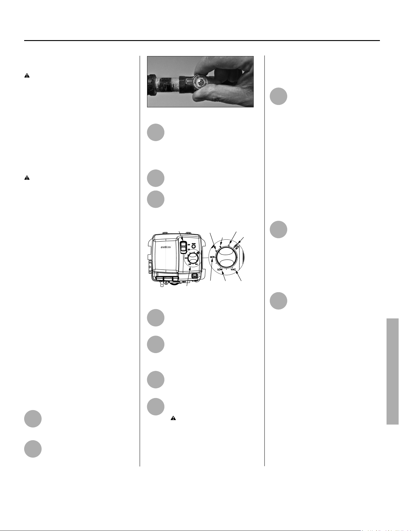
Power Vented Ultra Low Nox Gas Water Heater - Use and Care Guide • 27
OPERATION
OPERATION
Ligh ng Instruc ons
WARNING! Explosion Hazard –
• If you smell gas at any point during
this process, STOP! Turn off the
gas supply and follow the safety
steps on your water heater’s light-
ing label ( tled FOR YOUR SAFETY,
READ BEFORE LIGHTING).
• Replace viewport if glass is miss-
ing or damaged.
• Failure to do so can result in
death, explosion or fi re.
WARNING! Electrical Shock Hazard –
• Disconnect electrical power to
the water heater if service is to
be performed.
• Failure to do so can result in
death or electrical shock.
Read and understand these direc ons
thoroughly before a emp ng put your
water heater into service. Make sure
the viewport is not missing or dam-
aged. Make sure the tank is completely
fi lled with water before ligh ng and
ac va ng the water heater. Check
the ra ng plate near the gas control
valve to ensure the correct gas type.
Do not use this water heater with any
gas other than the one listed on the
ra ng plate. If you have any ques ons
or doubts, consult your gas supplier or
gas u lity company.
NOTICE! A newly installed water heater
will have air in the gas line. It may take
several ligh ng a empts to clear all the
air from the gas line.
Follow these steps to light the water
heater:
1
Disconnect the water heater’s
power plug from the ground-
ed 110/120 volt power supply.
2
Make sure the manual gas
valve for the water heater’s
supply line is OFF.
See
Figure 29.
Figure 29 - Gas valve in “on” position
3
Set the thermostat to the
lowest se ng by turning the
knob to “VAC”. See Figure 30.
DO NOT try to light the burner by
hand.
4
Set the switch to the OFF
posi on.
5
Wait fi ve minutes to clear out
any gas.
ON/OFF
SWITCH
70°F110°F120°F
130°F
140°F
150°F
155°F
TEMPERATURE SETTING DIAL
Figure 30 - Gas control valve.
6
Connect the water heater’s
power plug to a grounded
110/120 volt power supply.
7
Make sure the manual gas
valve for the water heater’s
supply line is ON.
See Figure 29.
8
Set the switch to the ON
posi on.
9
Set the thermostat to the
desired se ng
WARNING! Higher tem-
peratures increase the risk of scalding,
but even at 120°F, hot water can scald.
(See Table 1 on page 4.)
. Install
Thermosta c Mixing Valve(s) at each
point-of-use to reduce the risk of
scalding. The HOT on the gas control
valve indicates the preferred 120°F set
point.
10
IF the water heater will not
operate, follow these steps:
A. Set the thermostat to the lowest
se ng by turning the knob to
“VAC”. See Figure 30 - Gas control
valve.
B. Set the switch to the OFF posi on.
C. Unplug electrical service to the
water heater.
D. Turn off the gas at the manual gas
supply shutoff valve.
E. Call the technical assistance
hot line which is listed on your
warranty.
11
When a gas water heater is
fi rst lit and the tank is cold,
condensa on o en forms
inside the water heater. You may hear
drips or a sizzling sound when the water
heater is fi rst lit or, you may see a small
puddle on the fl oor. Condensa on is not
a leak and will go away once the tank
reaches normal opera ng temperature.
12
The air fi lter at the bo om of
the water heater must be
cleaned from me to me.
See the Maintenance sec on for steps
on cleaning the air fi lter.
Shut down Instruc ons
A. Set the thermostat to the lowest
se ng by turning the knob to
“VAC”. See Figure 30.
B. Set the switch to the OFF posi on.
C. Disconnect the water heater’s
power plug from the grounded
110/120 volt power supply.
Emergency Shut down
Should overhea ng occur or the gas
supply fail to shut off , turn off the water
heater’s manual gas control valve and
call a qualifi ed person.
Printed on: 7/6/2023 9:40:13 AM CT
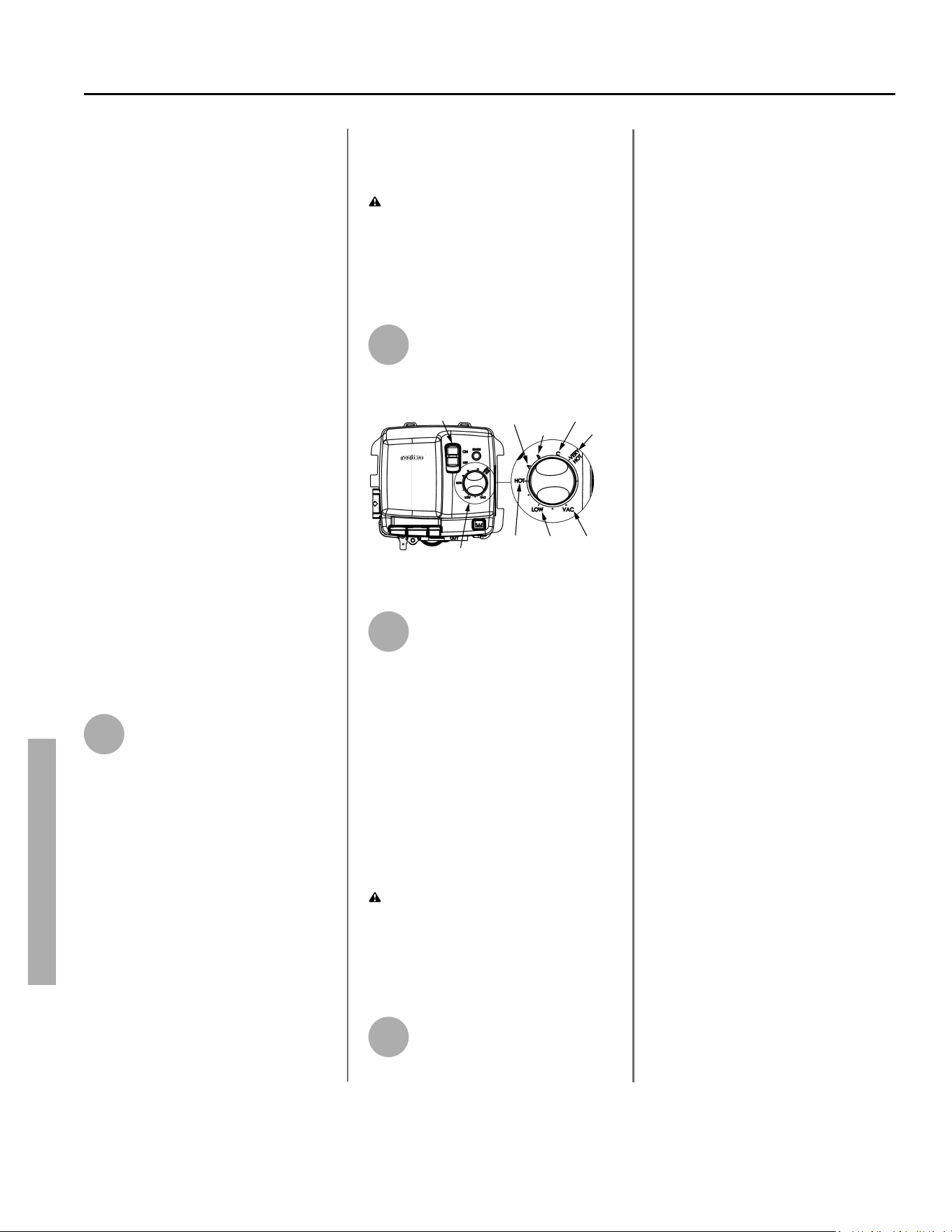
28 • Power Vented Ultra Low Nox Gas Water Heater - Use and Care Guide
OPERATION
NOTICE: This water heater is designed
to automa cally shut off in the event of
the following:
1. The water temperature exceeds
180°F (83°C.)
2. A blockage occurs in the combus-
on chamber air inlet, the fl ue gas
exhaust outlet, or both the inlet
and outlet.
3. The blower fails to operate or oper-
ates improperly.
4. The igni on of fl ammable vapors.
A high temperature limit switch or ECO
(Energy Cut Off ) in the tank is used to
shut off the unit if the water tempera-
ture exceeds 180°F (83°C.)
Temperature Control
System
Adjus ng the Temperature
You may adjust the water heater’s
temperature se ng, if desired. Using
the lowest hot water temperature that
meets your needs will also provide
energy effi cient opera on of the water
heater.
1
Set the gas valve to the desired
temperature. HOT on the gas
control valve/thermostat
indicates a set point of approximately
120°F, reducing the risk of scald injury.
It is the preferred star ng point for
se ng the temperature control.
You may wish to set a higher tempera-
ture to provide hot water for automa c
dishwashers or laundry machines, to
provide more hot water capacity, and
to reduce bacterial growth. Higher
tank temperatures (140°F) kill bacte-
ria that cause a condi on known as
“smelly water” and can reduce the
levels of bacteria that cause water-
borne diseases.
Water usage pa erns, as well as heat
from sources such as solar collectors
and ambient air can result in tempera-
tures higher than the thermostat set
point.
WARNING! Higher temperatures
increase the risk of scalding, but even
at 120°F, hot water can scald. (See
Table 1 on page 4.) Install Thermo-
sta c Mixing Valve(s) at each point-of-
use to reduce the risk of scalding.
2
To adjust the water heater’s
turn the temperature se ng
dial to the desired temperature.
ON/OFF
SWITCH
70°F110°F120°F
130°F
140°F
150°F
155°F
TEMPERATURE SETTING DIAL
Figure 31 - Temperature settings.
3
Wait for the water to heat up. If
you have no hot water a er
two hours, refer to the
Troubleshoo ng Sec on (see page 29).
NOTICE: If the tank is full of cold water,
condensa on may form inside the
water heater. This condensa on may
drop on the burner causing a sizzling
sound. In some cases, you may see a
small puddle on the fl oor. Condensa-
on is normal and should go away once
the tank reaches its normal opera ng
procedure.
WARNING! If you have increased
the temperature se ng and the
Thermosta c Mixing Valves are not set
properly (or not installed) you could
scald yourself while checking the
temperature.
4
Check water temperature at
several points of use in your
home (for example, bathtub
faucet, shower, or lavatory sink) and
adjust the Thermosta c Mixing Valves
as needed. If you aren’t sure how to
adjust the Thermosta c Mixing Valve
se ngs, or aren’t sure if you have
Thermosta c Mixing Valves, contact a
qualifi ed person.
Opera ng Modes
The gas control valve has two diff er-
ent opera ng modes: Standard and
Vaca on. The Standard mode allows
you to adjust the water temperature
to your desired se ng. The Vaca on
(WARM) mode sets the thermostat at
approximately 70°F and is recommend-
ed when not using hot water for an
extended period of me. The WARM
se ng also reduces energy losses and
keeps the tank from freezing during
cold weather but can cause a hydrogen
gas build up. See warning regarding
hydrogen gas on page 5.
OPERATION
Printed on: 7/6/2023 9:40:13 AM CT
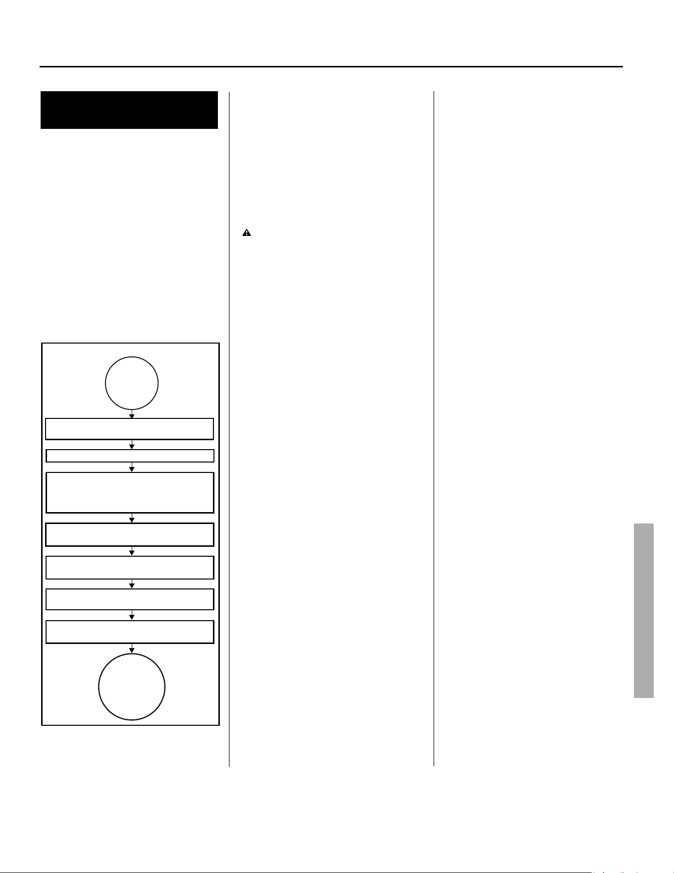
Power Vented Ultra Low Nox Gas Water Heater - Use and Care Guide • 29
TROUBLESHOOTING
TROUBLESHOOTING
NOTICE
If the LEDs on your gas control valve/
thermostat indicate an error code, refer
to the chart on pages 32.
Water Heater
Opera on
The figure below shows the water
heater’s sequence of operation when
a call for heat is initiated. (This is
when the water heater begins to
heat water based on the thermostat
setting.) The ignition control will try
to light the burner three times. If
the ignition control does not detect
ignition, it will enter lock-out mode,
indicated by a three flash error code.
^ĞƋƵĞŶĐĞŽĨKƉĞƌĂƟŽŶ
Heater control checks to ensure blower
pressure switch is open.
Blower is energized.
Control checks to ensure pressure switch
ĐůŽƐĞƐŝŶĚŝĐĂƟŶŐďůŽǁĞƌŝƐŽƉĞƌĂƟŶŐĂŶĚ
ƚŚĞƌĞĂƌĞŶŽǀĞŶƟŶŐďůŽĐŬĂŐĞƐ
(inlet or outlet).
Igniter is energized and
main gas valve is opened.
Main burner comes on and the
ŇĂŵĞŝƐƐĞŶƐĞĚďLJĐŽŶƚƌŽů
DĂŝŶďƵƌŶĞƌĐŽŶƟŶƵĞƐƟůůƚŚĞǁĂƚĞƌŝŶƚŚĞ
ƚĂŶŬƌĞĂĐŚĞƐƚŚĞƌŵŽƐƚĂƚƐĞƫŶŐ
DĂŝŶďƵƌŶĞƌƐŚƵƚƐŽīůŽǁĞƌĐŽŶƟŶƵĞƐĨŽƌ
ĂƉŽƐƚƉƵƌŐĞƟŵĞ
Heater
thermostat
calls for
heat.
Heater
remains on
ƐƚĂŶĚďLJ
ƵŶƟůŶĞdžƚ
call for
heat.
Figure 32 - Sequence of Operation
No Hot Water
If your water heater is not producing
hot water, refer to “TROUBLESHOOT-
ING” on page 29.
Insuffi cient Hot Water
or Slow Hot Water
Recovery
WARNING! Because of the in-
creased risk from scalding, if you set
the water heater’s gas control knob
higher than 120°F, install Thermosta c
Mixing Valves at each point-of-use.
Due to the increased risk of scalding,
do not set the temperature of the
Thermosta c Mixing Valves above
120°F.
If the hot water is simply not warm
enough, there are several possible
causes:
• Faulty Thermosta c Mixing Valve
in a faucet or shower control
(check other faucets in the house
for hot water).
• Water heater’s capacity too small
(or usage too high).
• Reversed plumbing connec ons
or melted dip tube (usually found
soon a er new installa on).
• Plumbing leak.
• Sediment or lime build up in the
bo om of the tank.
• Defec ve thermostat or ECO
(energy cut-off switch)
• For other poten al causes, refer
to “TROUBLESHOOTING” on page
29.
Thermosta c Mixing Valves. If the
hot water is simply not warm enough,
make sure the faucet you are checking
doesn’t have a defec ve Thermosta c
Mixing Valve. Many shower controls
now have built-in mixing valves. If
these devices fail, they can reduce the
amount of hot water the shower or
faucet delivers even though there is
plenty of hot water in the tank. Always
check the water temperature at several
faucets to make sure the problem is
not in a faucet or shower control.
Undersized Water Heater. If your
water heater runs out of hot water
quickly, it may be too small for your
needs. If the water heater is old, con-
sider replacing it with a larger model. If
the water heater is in good condi on,
you may be able to meet your fam-
ily’s hot water needs with the exis ng
water heater by installing Thermosta c
Mixing Valves at each point-of-use and
then turning the gas control knob to a
higher se ng.
You can also reduce your home’s hot
water needs by washing clothes in cold
water, installing fl ow restrictors on
shower heads, repairing leaky faucets,
and taking other conserva on steps.
Reversed Connec ons or Melted Dip
Tube. Check the hot and cold water
connec ons and make sure your
home’s hot water pipe is connected
to the hot water outlet on the water
heater. Usually, reversed connec ons
are found soon a er the installa on
of a new unit. If copper pipes were
soldered while they were a ached to
the water heater, the dip tube may
have melted. The dip tube is a long,
plas c tube inside the tank a ached
to the cold water inlet. If the dip tube
is melted, the nipple dip tube assem-
bly can be removed, and replaced
with a new one.
Plumbing Leak. Even a small leak
in the hot water side of the home’s
plumbing system can make it appear
that the water heater is producing
li le to no hot water. In this case, the
burner will be on all or almost all the
Printed on: 7/6/2023 9:40:13 AM CT

30 • Power Vented Ultra Low Nox Gas Water Heater - Use and Care Guide
TROUBLESHOOTING
TROUBLESHOOTING
me, yet you will have very li le hot
water. Locate and repair the leak.
Sediment or Lime in Tank. With an ex-
is ng water heater, if you have some
hot water but not as much as you’re
used to, there may be a build up of
sediment or lime on the bo om of the
tank. Sediment or lime build up can
reduce the effi ciency of your water
heater. Heavy deposits can damage
the water heater. See the Mainte-
nance sec on for steps on draining
and fl ushing the water heater.
Failure of the thermostat or ECO
(energy cut-off switch). If either
component failed, the water will not
be heated as expected. Replace the
thermostat/ECO as required.
Temperature Too High
Adjust the thermostat on the water
heater to a lower se ng. Install or
adjust Thermosta c Mixing Valves
for each point-of-use (see the valve
manufacturer’s instruc ons).
Low Water Pressure
Check both the cold and hot water
at a sink to determine if the lower
pressure is only on the hot water side.
If both hot and cold faucets have low
pressure, call your local water u lity.
If the low pressure is only on the hot
water side, the primary causes are:
• Melted heat traps or dip tube. Sol-
dering copper pipes while they are
connected to the water heater can
melt the heat traps inside the hot
and cold water connec ons or the
dip tube (cold water side). Melted
heat traps or a melted dip tube
can restrict the fl ow of hot water.
If that’s the case, replace the heat
traps or dip tube.
• Par ally closed supply valve. Open
the water heater’s supply valve fully.
Drips from T&P Relief
Valve Discharge Pipe
A small amount of water dripping
from the Temperature and Pressure
(T&P) Relief Valve usually means the
home’s water pressure is too high
and/or you need a Thermal Expan-
sion Tank. See page 16 for more
informa on.
A large amount of hot water coming
from the T&P discharge pipe may be
due to the tank overhea ng. If the
T&P relief valve is discharging large
amounts of very hot water, turn the
gas supply valve off and call a quali-
fi ed person.
WARNING! Do not cap or plug the
T&P Relief Valve or discharge pipe,
and do not operate the water heater
without a func oning T&P Relief
Valve—this could cause an explosion.
Water Pressure too High. High water
pressure can cause the T&P Relief
Valve to drip. Install a Pressure Re-
ducing Valve (PRV) on the main cold
water supply line. Adjust the PRV to
between 50 and 60 psi.
Thermal Expansion Tank. Install a
Thermal Expansion Tank. If a Thermal
Expansion Tank is already installed
and the T&P Relief Valve discharge
pipe drips, the home’s water pressure
may be too high or the Thermal Ex-
pansion Tank may be defec ve. Refer
to the instruc ons that came with
the Thermal Expansion Tank for more
informa on.
Debris. In rare cases, debris can s ck
inside the T&P Relief Valve, prevent-
ing the valve from sealing fully. In that
case, the T&P Relief Valve discharge
pipe will drip. You may be able to
clear debris from the T&P Relief Valve
by manually opera ng the valve,
allowing small quan es of water to
fl ush out the debris. See the label on
the T&P Relief Valve for instruc ons.
WARNING! When manually
opera ng the temperature-pressure
relief valve, make sure that no one is
in front of or around the discharge
outlet. The water may be extremely
hot and could cause severe burns.
Also ensure that the water discharge
will not cause property damage.
If the water pressure is between 50
and 60 psi, a Thermal Expansion Tank
is installed and properly pressurized,
and the valve has been cleared of any
debris, but it s ll drips, the valve may
be broken. Have a qualifi ed person
replace the T&P Relief Valve.
Water Odor
Harmless bacteria normally present in
tap water can mul ply in water heat-
ers and give off a “ro en egg” smell.
Although elimina ng the bacteria that
causes “smelly water” is the only sure
treatment, in some cases, the stan-
dard anode rod that came with your
water heater can be replaced with a
special zinc anode rod which may help
reduce or eliminate the odor. Contact
a qualifi ed person.
NOTICE: To protect the tank, an anode
rod must be installed in the water
heater at all mes or the warranty is
void.
In cases where the “ro en egg” smell
is very strong, you could increase the
tank temperature to 140°F in order to
reduce bacterial growth in the tank.
WARNING! Because higher
temperatures increase the risk of
scalding, if you set the thermostat(s)
higher than 120°F, Thermosta c
Mixing Valves at each point-of-use
are par cularly important.
Printed on: 7/6/2023 9:40:13 AM CT
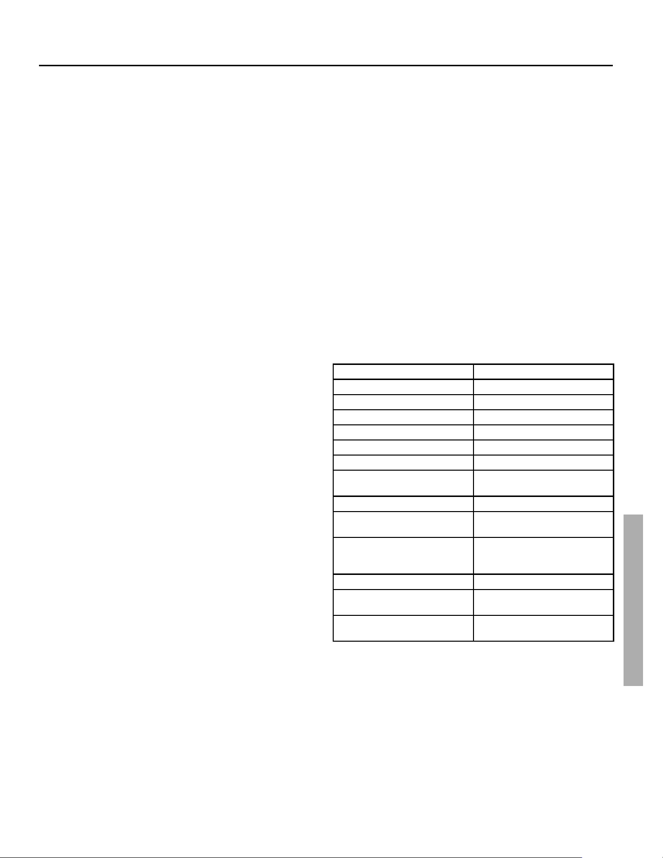
Power Vented Ultra Low Nox Gas Water Heater - Use and Care Guide • 31
TROUBLESHOOTING
TROUBLESHOOTING
These guidelines should be utilized by a qualifi ed service agent.
LOCKOUTS
So Lockout
• • Occurs when a system safety device trips to break the
sequence of operation. The control will try to start the system in
a timed basis but will not reinstate operation until the failure is
corrected.
Hard Lockout
• Occurs when the main controller fails and must be replaced.
RESETTING THE HEATER CONTROL
• Soft lockouts as diagnosed by the system error codes require
the gas control to be reset.
• To reset the control, slide the “ON/OFF” switch to the “OFF”
position. Wait for 10 seconds and move the switch back to the
“ON” position.
• If the problem that caused the control to lock out has not been
corrected, the control will remain locked out, or again go into
lock out.
IGNITION STATE TIMING
Pre-purge 5 Seconds
Hot Surface igniter (HSI) Warm-up 10 Seconds
Ignition Activation Period (IAP) 3.5 Seconds
Flame Recognition Period (FRP) 0.5 Seconds
Trial For Ignition IAP + FRP
Purge when flame not sensed. 30 seconds
Flame Failure
Response Time
2 seconds max
(@ 1uA flame current)
Post-purge 30 seconds
Pressure Switch (PS)
Prove Period
2 minutes
Pressure Switch (PS)
Fault Delay (failed
open/closed)
2 minutes
Soft Lockout 20 minutes (Ignition reattempt)
Energy Cut Off
(ECO) Limit Lockout
Indefinite (clear fault to restart in 15
seconds or less)
Flammable Vapor (FV) Sensor
Lockout
Indefinite (see “Resetting The Heater
Control”)
Soo ng
Is the result of improper combustion.
Check venting to ensure no blockages
are present. Confirm all exhaust piping
is properly sized, see “Combustion
and Ventilation Air Supply” section on
page 7. A wrong gas type may also
cause sooting, see ”Gas Piping” on
page 15.
Heater Lights But Goes
out in 4-5 Seconds
Make sure the correct vent restrictor
is installed. Follow the instructions in
the “Venting” section on page 11. If
the issue continues have a qualified
person check the outlet polarity.
Improperly sized gas piping may also
cause this issue, see ”Gas Piping” on
page 15.
Hot Surface Igniter
Not Glowing Following
Warm-Up Period
The hot surface igniter should glow
when during the warm-up period if it
fails to do so follow the instructions
on page 27-28 to turn off your water
heater and contact a qualified person
to check the system.
Printed on: 7/6/2023 9:40:13 AM CT
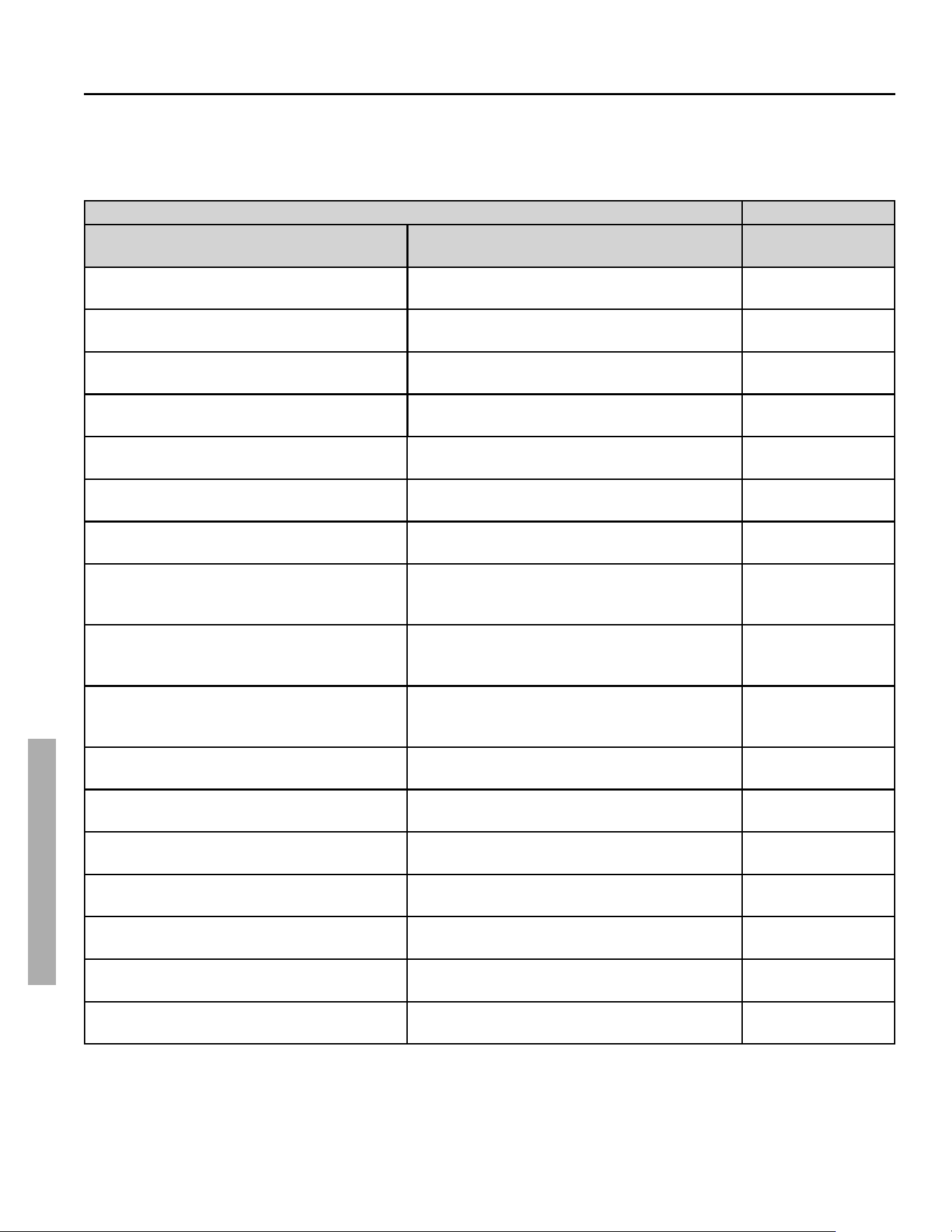
32 • Power Vented Ultra Low Nox Gas Water Heater - Use and Care Guide
TROUBLESHOOTING
TROUBLESHOOTING
SYSTEM STATUS AND ERROR CODES
The micro-controller inside the gas control monitors the ignition sequence, temperature settings, and overall operation of
the heater. If any of these parameters does not operate properly the controller will shut down the water heater, diagnose
the failure and fl ash an error code. The table below lists the System Status Codes for the Honeywell control. Refer to it
and to the “Ignition State And Timing” to diagnose the problem before attempting corrective action.
ERROR CODES
LED Flash Sequence Control Status
Corrective
Action Number
Short flash
once every four seconds
IDLE (no call for heat,
no fault conditions)
1
“Heartbeat”,
alternates bright/dim
Call For Heat
(no fault conditions)
2
One Flash,
three second pause
Low Flame Signal
(control continues to operate)
3
Two Flash,
three second pause
Pressure Switch Failed Closed 4
Three Flash,
three second pause
Pressure Switch Failed Open 5
Four Flash,
three second pause
ECO (Energy Cut Off) Limit Lockout
thermostat temperature limit was exceeded.
6
Five Flash,
three second pause
Flame Out Of Sequence 7
Six-One Flash,
three second pause
Soft Lockout
- Retry Limit
- Failed Trial For Ignition
8
Six-Two Flash,
three second pause
Soft Lockout
- Recycle Limit
- Pressure Switch/High Limit opened
9
Six-Three Flash,
three second pause
Soft Lockout
- Recycle Limit
- Flame Lost
10
Six-Four Flash, three second pause
Soft Lockout
- Flame out of Sequence Sensed
11
Seven Flash,
three second pause
Flammable Vapor Sensor (FVS) Lockout 12
Eight-One Flash,
three second pause
Flammable Vapor Sensor FVS Fault Detected 13
Eight-Two Flash,
three second pause
Temperature Sensor Fault Detected 14
Eight-Three Flash,
three second pause
Electronics Fault Detected 15
Eight-Four Flash,
three second pause
Valve Fault Detected 16
Hardware Fault Lockout Indefinite 17
READING THE LED FLASH SEQUENCE.
The LED indicator light is active when the gas valve/thermostat is in operation. The light will normally show a flash sequence of a short flash once every four seconds
or a “Heartbeat” of alternating bright/dim. Multiple flash codes indicate an error and can be read as follows: Example: Corrective Action Number 9, Six-Two Flash, three
second pause. For this code, the LED indicator light will make six bright flashes, pause for one second and then make two more bright flashes. The LED will pause for
three seconds and repeat the six-two cycle of flashes.
Printed on: 7/6/2023 9:40:13 AM CT
Power Vented Ultra Low Nox Gas Water Heater - Use and Care Guide • 33
TROUBLESHOOTING
CORRECTIVE ACTIONS
See the table below for corrective actions corresponding to the Corrective Action Number in the “System Status And Error Codes” section above. If following those
corrective actions does not resolve the error, refer to “Other Symptoms” table later in this manual.
Corrective
Action
Number
Corrective Action
1 Normal operation, no action necessary.
2 Normal operation, no action necessary.
3 1. Flame rod not properly seated in flame, reposition rod.
2. Clean flame sensor rod with fine steel wood to remove any buildup which may prevent flame sensing
4 1. Check that blower operates and does not have any blockages.
2. Check that all wiring is correct.
3. Ensure the air pressure sensing tubes are properly connected and not kinked or damaged.
4. Ensure the air pressure switch is correct and the air pressure switch (N.O.) is not bypassed (jumpered).
5. Turn power to the unit “OFF” – check for continuity of the air pressure switch (N.O.) with wires disconnected;
a. If the pressure switch contacts show continuity (closed circuit), replace the pressure switch,
b. If the pressure switch contacts are open and all wiring is correct, replace the Gas Control.
5 1. If the blower does not run after resetting the heater, check for 120 VAC to the blower when the heating cycle begins.
a. If the Gas Control does not energize the blower - replace the Gas Control.
b. If the blower fails to start when energized:
i. Turn power to the heater “OFF” – check if the capacitor is connected;
ii. Turn power to the heater “OFF” – check the capacitor rating (3uF +/-5%);
iii. Turn power to the heater “OFF” - replace the blower assembly.
2. Ensure the air pressure sensing tubes are properly connected and not kinked or damaged;
3. Check continuity of the vent temperature limit switch – replace switch if contact remain open.
4. With the blower running, check continuity of the air pressure switch (N.C.) – replace switch if contact remain open.
5. Ensure the correct size of exhaust and air intake pipes were used per the instruction manual for vent length. Ensure maximum number of
elbows or equivalent feet of both pipes was not exceeded.
6. Ensure there are no obstructions in the exhaust and air intake pipes.
7. If there are excessive restrictions in the air intake pipe the air pressure switch (N.C.) will open.
8. Check air pressure switch performance - Check blower vacuum with a manometer - Compare with air pressure switch (N.O.) setting. If the
air pressure switch proves defective – replace the air pressure switch (N.O.).
9. If the air pressure switch (N.O.) performance test results prove the air pressure switch is working properly, and all other steps are followed,
and fault code persist – replace the control.
6 Resetting the ECO (Energy Cut-Out) requires manual intervention. It cannot be reset by cycling power to the control.
Reset Procedure:
1. Manual reset is performed by turning the set point knob to lowest set point position for a minimum of 10 seconds and then return it to the
desired set point.
2. The manual reset of the ECO can only be performed 2 times, after the ECO trips a third time, the gas valve will enter a hard lock out where
the gas control will need to be replaced.
7 1. Turn the power “OFF” for 10-20 seconds then “ON” again to clear the fault code.
2. Clean flame sensor rod with fine steel wool to remove any buildup which may prevent flame sensing.
3. Flame rod not properly seated in flame, reposition rod.
4. Replace the control if the fault code persists.
8 1. Gas supply is turned off or gas pressure is too low. Ensure supply pressure and manifold gas pressures are within requirements. Manifold
pressure is nonadjustable, if gas supply pressure proves correct and manifold pressure is off by more than 0.3” WC replace the control.
2. Low supply voltage - should be 115 - 125 VAC
3. Ensure flame sensor is making good contact with the burner flame and flame is steady.
4. Ensure flame sensor is clean, use ultra- fine steel wool to clean flame sensor.
5. Ensure the Hot Surface Igniter is positioned properly to provide consistent ignition.
6. Check for any cracks in igniter assembly ceramic insulators - replace igniter assembly if damaged.
7. Check resistance of igniter at room temperature (at the plug). Replace the igniter if resistance is not within 42-76 ohms at room
temperature.
8. Ensure correct size of exhaust and air intake pipes were used per the instruction manual for vent length. Ensure maximum number of
elbows or equivalent feet of both pipes was not exceeded.
TROUBLESHOOTING
Printed on: 7/6/2023 9:40:13 AM CT
34 • Power Vented Ultra Low Nox Gas Water Heater - Use and Care Guide
TROUBLESHOOTING
Corrective
Action
Number
Corrective Action
9 1. If the blower does not run after resetting the heater, check for 120 VAC to the blower when the heating cycle begins.
a. If the Gas Control does not energize the blower - replace the Gas Control.
b. If the blower fails to start when energized:
i. Turn power to the unit “OFF” – check if the capacitor is connected;
ii. Turn power to the unit “OFF” – check the capacitor rating (3uF +/-5%);
iii. Turn power to the unit “OFF” - replace the blower assembly.
2. Ensure the air pressure sensing tubes are properly connected and not kinked or damaged;
3. Check continuity of the vent temperature limit switch – replace switch if contacts remain open.
4. With the blower running, check continuity of the air pressure switch (N.C.) – replace switch if contact remain open.
5. Check continuity of the High Limit switch (N.C.) – replace switch if contact remain open.
6. Ensure correct size of exhaust and air intake pipes were used per the instruction manual for vent length. Ensure maximum number of
elbows or equivalent feet of both pipes was not exceeded.
7. Ensure there are no obstructions in the exhaust and air intake pipes.
8. If there are excessive restrictions in the air intake pipe the air pressure switch (N.C.) will open.
9. Check air pressure switch performance - Check blower vacuum with a manometer - Compare with air pressure switch (N.O.) setting. If the
air pressure switch proves defective – replace the air pressure switch (N.O.).
10. If the air pressure switch (N.O.) performance test results prove the air pressure switch is working properly, and all other steps are followed,
and fault code persist – replace the gas control valve.
10 1. Gas supply is turned “OFF” or gas pressure is too low. Ensure supply pressure and manifold gas pressures are within requirements.
Manifold pressure is nonadjustable. If supply pressure proves correct and manifold, pressure is off by more than 0.3” WC replace the
control.
2. Low supply voltage - should be 115 - 125 VAC
3. Ensure flame sensor is making good contact with the burner flame and flame is steady.
4. Ensure the flame sensor is clean, use ultra-fine steel wool to clean flame sensor.
5. Ensure the Hot Surface Igniter is positioned properly to provide consistent ignition.
6. Check for any cracks in igniter assembly ceramic insulators - replace igniter assembly if damaged.
7. Check resistance of igniter at room temperature (at the plug). Replace the igniter if resistance is not within 42-76 ohms at room
temperature.
8. Ensure correct size of exhaust and air intake pipes were used per the instruction manual for vent length. Ensure maximum number of
elbows or equivalent feet of both pipes was not exceeded.
9. Ensure vent termination restrictor/fitting is installed, and is correct in accordance with venting tables.
11 1. Turn the power “OFF” for 10-20 seconds then “ON” again to clear the fault code.
2. Replace the gas control valve if fault code persists.
12 1. Flammable vapor sensed indicates the presence of flammable vapors, or other chemicals which have activated the flammable vapor sensor.
Ensure no flammable vapors, chemicals or littler boxes which release ammonia are near the water heater, and replace the flammable vapor
sensor. Once replaced, reset the control using the “RESETTING THE HEATER CONTROL” procedure on page 31.
13 1. Flammable Vapor Sensor (FVS) Fault Detected means the signal to and from the FVS has been interrupted, or the FVS has been jumped/
bypassed. Physical damage including exposure to water will damage the FVS, requiring replacement. If the FVS has not been exposed to
water, and is not damaged, ensure the FVS connections are secure. If fault continues, replace the FVS. Once replaced, reset the control
using the “RESETTING THE HEATER CONTROL” procedure on page 31.
14 1. Turn the power “OFF” for 10-20 seconds then “ON” again to clear the fault code.
2. Replace the control if the fault code persist.
15 1. Turn the power “OFF” for 10-20 seconds then “ON” again to clear the fault code.
2. Replace the control if the fault code persist.
16 1. Turn the power “OFF” for 10-20 seconds then “ON” again to clear the fault code.
2. Replace the control if the fault code persist.
17 1. Control has failed. If resetting the control does not clear the fault code, replace the control.
TROUBLESHOOTING
Printed on: 7/6/2023 9:40:13 AM CT
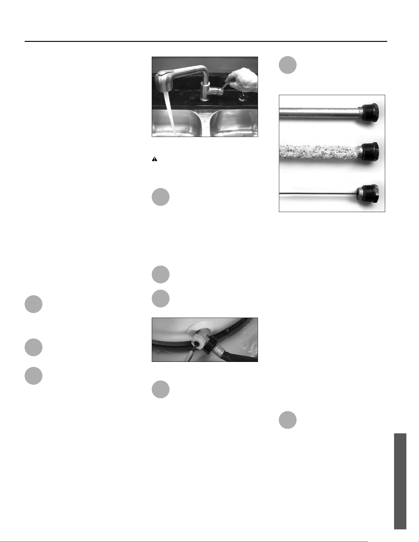
Power Vented Ultra Low Nox Gas Water Heater - Use and Care Guide • 35
REPAIR PARTS
MAINTENANCE
Rou ne Maintenance
Rou ne maintenance will help your
water heater last longer and work bet-
ter. If you can’t perform these rou ne
maintenance tasks yourself, contact a
qualifi ed person.
Draining and Flushing the Water
Heater
Tap water contains minerals that can
form sediment in the bo om of the
tank. The amount of sediment formed
depends on the hardness of your
tap water, the temperature se ngs,
and other variables. We recommend
draining and fl ushing the water heater
a er the fi rst six months of opera on
to determine the amount of sediment
build up. If there is li le sediment, drain
and fl ush the tank annually. If there is a
lot of sediment, drain and fl ush the tank
more o en. Draining sediment extends
the life of the water heater.
To Drain and Flush the Tank:
1
Turn off the gas to the water
heater at the manual gas
supply shut-off valve. (See
Figure 40 on page 37.)
2
Turn off the electrical supply to
the water heater.
3
Open a hot water faucet and
let the hot water run un l it is
cool. This may take 10 minutes
or longer.
Figure 33 - Let the hot water run until it is cool.
WARNING! Be sure the water runs
cool before draining the tank to reduce
the risk of scalding.
4
Connect a garden hose to the
drain valve and place the other
end of the hose in a drain,
outside, or in buckets. Note that
sediment in the bo om of the tank may
clog the valve and prevent it from
draining. If you can’t get the tank to
drain, contact a qualifi ed person.
5
Turn the cold water supply
valve OFF.
6
Open the drain valve on the
water heater.
Figure 34 - Draining the water heater.
7
Open a hot water faucet to
help the water in the tank
drain faster.
8
Remove and inspect the anode
rod and replace if depleted.
The anode rod requires a
1-1/16” socket.
Figure 35 - Anode rods from new (top) to par-
tially depleted (middle) to fully depleted stage
(bottom).
Anode Rod. The anode rod is a sacrifi -
cial metal rod that helps avoid corrosion
and premature failure (leaks) in the
tank. The anode rod is a consumable
item. Inspect the anode rod a er the
fi rst six months of opera on when you
drain and fl ush the tank. Replace the
anode rod if it is substan ally worn out
or depleted. Therea er, inspect the
anode rod annually or more frequently
if needed. If you use a water so ener,
your anode rod will deplete faster than
normal. Inspect the anode rod more
frequently, replacing the anode rod if
it is depleted. Obtain a new anode rod
or have a qualifi ed person replace it.
(Anode rods are a consumable item and
are not covered under warranty.)
9
If a large amount of sediment
was present when the tank
was drained, fl ush the tank by
opening the cold water supply valve
and le ng the water run un l no more
sediment drains from the tank. Close
the drain valve when you are done.
Printed on: 7/6/2023 9:40:13 AM CT
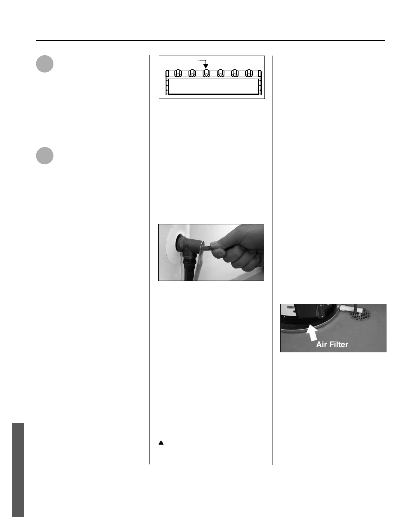
36 • Power Vented Ultra Low Nox Gas Water Heater - Use and Care Guide
MAINTENANCE
10
Refi ll the tank by opening the
cold water supply valve. Make
sure a hot water faucet is
open and the drain valve is closed.
Allow a hot water faucet to run full for
at least three minutes to make sure the
tank has all the air removed and is
completely full of water. Once you are
certain the tank is completely full of
water, close the hot water faucet.
11
Put the water heater into
service using the instruc ons
on page 27 and set the
thermostat to the desired tempera-
ture. It may take an hour or more for
the tank of cold water to heat up.
Visual Inspec on
On an annual basis, visually inspect the
ven ng and air supply system, piping
systems, main burner, fl ame sense rod,
and air fi lter.
Check the water heater for the following:
• Obstruc ons, damage, or deterio-
ra on in the ven ng system. Make
sure the ven la on and combus-
on air supplies are not obstruct-
ed. Check the air fi lter for dust or
other debris and clean if needed.
• Build up of soot and carbon on the
main burner and fl ame sense rod.
The burner may be cleaned with
soap and hot water. The fl ame
sense rod on the hot surface igniter
assembly may be cleaned with steel
wool.
• Inspect the burner flames through
the viewport and compare them
to Figure 36 - Burner Flames.
Flames should be very small with
a blue haze and small amounts
of yellow or orange at the edges.
After several minutes of operation,
the burner screen may glow red.
If large flames are observed at any
time, shut-off unit and call a quali-
fied person.
Correct flame
soft blue
Figure 36 - Burner Flames
• Leaking or damaged water and gas
piping.
• Remove any fl ammable, corrosive
or combus ble materials near the
water heater.
If you lack the necessary skills required
to properly perform this visual inspec-
on or if the burner and/or hot surface
igniter assembly need to be cleaned, get
help from a qualifi ed person.
T&P Relief Valve Maintenance
Figure 37 - T&P Relief Valve.
Read and follow the opera ng and
annual maintenance instruc ons
provided by the manufacturer of the
T&P Relief Valve (yellow label a ached
to T&P Relief Valve). Minerals in the
water can form deposits that cause
the valve to s ck or create blocked
passages, making the T&P Relief Valve
inopera ve. Follow these guidelines:
• At least annually, operate the T&P
Relief Valve manually to ensure the
waterways are clear and the valve
mechanism moves freely (above).
Before opera ng the valve manually,
check that it will discharge in a place
for secure disposal.
WARNING! Hot water will be
released. Before opera ng the T&P
relief valve manually, check that it will
discharge in a safe place. If water does
not fl ow freely from the end of the
discharge pipe, turn the gas control
knob to the OFF posi on and call a
qualifi ed person to determine the
cause.
• At least every fi ve years, have a
qualifi ed person inspect the T&P
Relief Valve and discharge pipe.
Damage caused by corrosive water
condi ons, mineral deposits, or
other problems can only be de-
termined when a qualifi ed person
removes and inspects the valve
and its components.
A dripping T&P Relief Valve is usually
caused by the home’s water pressure
being too high or the lack of a Thermal
Expansion Tank. If your T&P Relief
Valve drips, see “Drips from T&P Relief
Valve Discharge Pipe” on page 30
.
A T&P relief valve that has been al-
lowed to drip for an appreciable period
of me should be inspected for mineral
buildup. See T&P relief valve tag for
more informa on.
Inspect and Clean the Air Filter
Figure 38 - Clean air filter periodically.
An air fi lter should be installed around
the base of the water heater. At least
annually inspect the air fi lter and check
for a build-up of dust or debris.
Vacuum the fi lter to remove any dust
or debris. If an oily residue is present
on the fi lter, wash it in soap and water,
then dry the fi lter.
MAINTENANCE
Printed on: 7/6/2023 9:40:13 AM CT
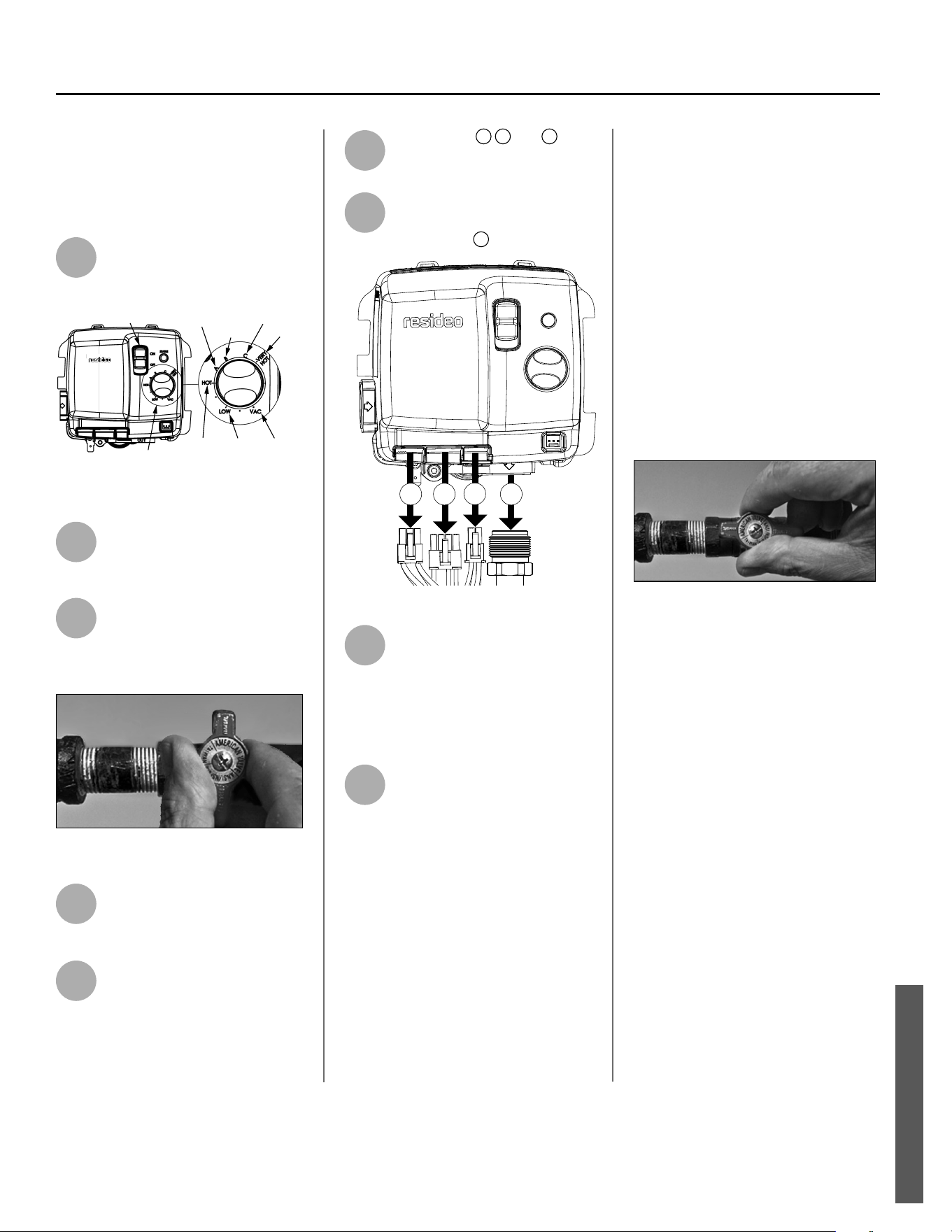
Power Vented Ultra Low Nox Gas Water Heater - Use and Care Guide • 37
MAINTENANCE
MAINTENANCE
Removing and Replacing the Gas
Control Valve/Thermostat
Removing the Gas Control Valve/
Thermostat:
1
Set the Switch to the “OFF”
posi on.
ON/OFF
SWITCH
70°F110°F120°F
130°F
140°F
150°F
155°F
TEMPERATURE SETTING DIAL
Figure 39 - Switch and temperature controls.
2
Disconnect the water heater’s
power plug from the grounded
110/120 volt power supply.
3
Make sure the manual gas
valve for the water heater’s
supply line is OFF.
See Figure 40.
Figure 40 - Gas valve in “off” position
4
Set the thermostat to the
lowest se ng by turning the
knob to “VAC”. See Figure 40.
5
Drain the water heater. Refer
to the “Draining and Flushing
the Water Heater” section on
page 36.
6
Disconnect
A
B
and
C
.
from the thermostat
(See Figure 41).
7
Disconnect the manifold tube
at the gas control valve/
thermostat
D
(Figure 41).
A B
C
D
Figure 41 - Gas valve connections at thermostat.
8
Disconnect the ground joint
union in the gas piping.
Disconnect the remaining pipe
from the gas control valve/thermostat.
(Refer to “COMPLETED INSTALLATION”
on page 2.)
9
To remove the gas control
valve/thermostat, thread a 4”
sec on of gas pipe into the
inlet and use it to turn the gas control
valve/thermostat (counterclockwise).
Do not use a pipe wrench or equivalent
to grip body. Damage may result,
causing leaks. Do not insert any sharp
objects into the inlet or outlet connec-
ons. Damage to the gas control valve/
thermostat may result.
Replacing Gas Control Valve/Thermostat:
To replace the gas control valve/thermo-
stat, reassemble in reverse order. When
replacing the gas control valve/
thermostat, thread a 4” sec on of gas
pipe into the inlet and use it to turn the
gas control valve/thermostat (clockwise).
DO NOT OVER TIGHTEN; damage may
result.
• Be sure to use approved thread sealant
tape or pipe joint compound on the gas
piping connec ons and fi ng on
the back of the gas control valve that
screws into the tank.
Figure 42 - Gas valve in “on” position.
• Turn the gas supply on and check
for leaks. Test the water heater with
the main burner on by brushing on an
approved noncorrosive leak detec on
solu on. Bubbles forming indicate a
leak. Correct any leak found.
• Be sure tank is completely fi lled with
water before ligh ng and ac va ng the
water heater. Follow the “Lighting In-
structions” section on page 27.
• If addi onal informa on is required,
contact the Service Department at the
number listed on your warranty.
Printed on: 7/6/2023 9:40:13 AM CT
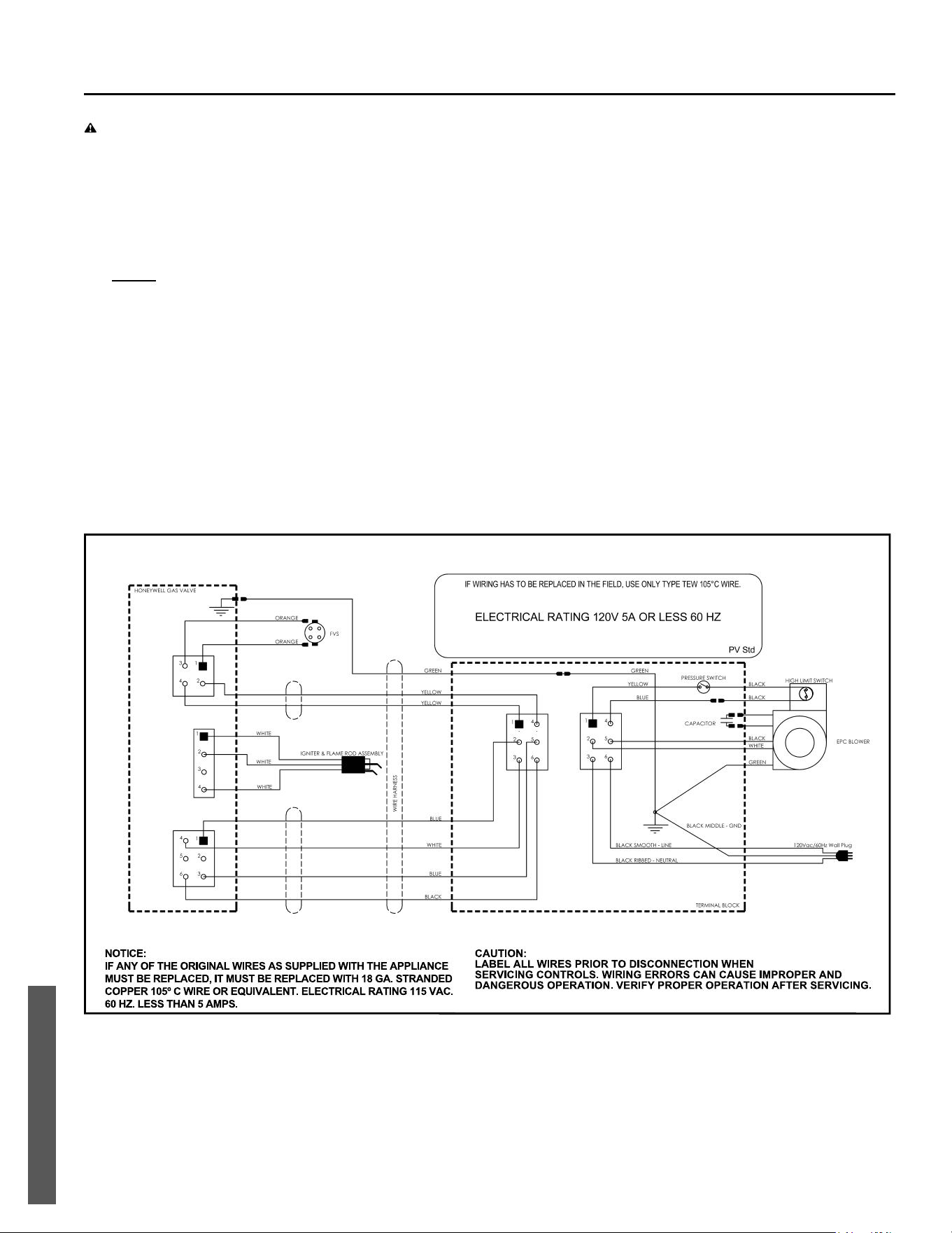
38 • Power Vented Ultra Low Nox Gas Water Heater - Use and Care Guide
ELECTRICAL CONNECTIONS
ELECTRICAL
WARNING! Electrical Shock Hazard –
• Disconnect electrical power to the water heater if service is to be performed.
• Failure to do so can result in death or electrical shock.
Before plugging in the water heater, always make sure:
• The voltage and frequency correspond to that specified on the water heater wiring diagram.
• The electrical outlet has the proper overload fuse or breaker protection.
• Do not use an extension cord to connect the water heater to an electrical outlet.
• The water heater and the outlet are properly grounded.
• Installed in accordance with prevailing provisions of local codes, or in the absence of such, National Electric Code, ANSI/
NFPA 70.
• Always reference the wiring diagram for the correct electrical connections.
• This water heater is a polarity sensitive appliance and will not operate properly if the power supply polarity is reversed.
Power to this water heater must be wired properly (correct polarity).
After making all electrical connections, completely fill the tank with water and check all connections for leaks. Open the
nearest hot water faucet and let it run for 3 minutes to purge the water lines of air and sediment and to ensure complete filling
of the tank. The electrical power may then be turned on. Verify proper operation after servicing.
HIGH LIMIT SWITCH (N.C.)
Figure 43 - Wiring Diagram
Printed on: 7/6/2023 9:40:13 AM CT
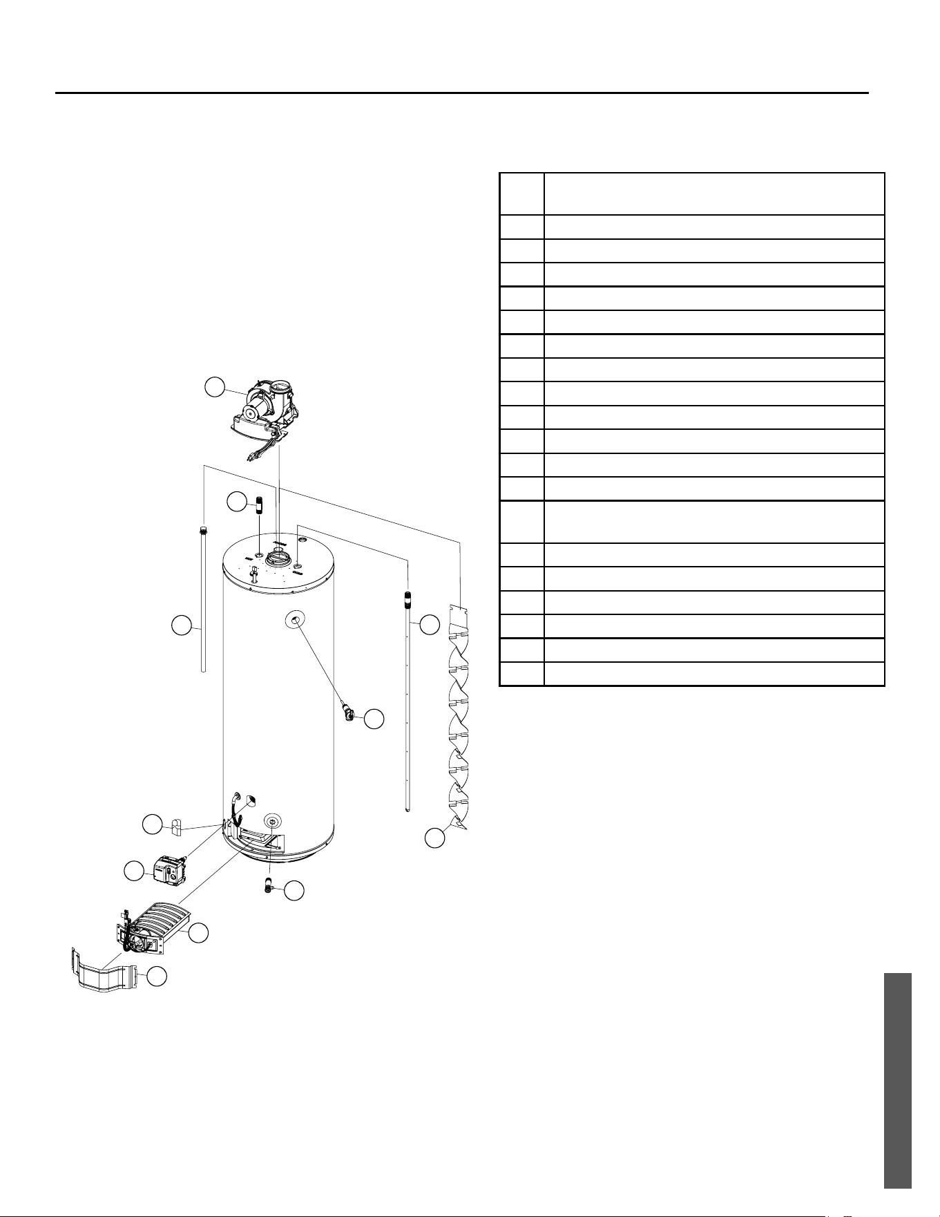
Power Vented Ultra Low Nox Gas Water Heater - Use and Care Guide • 39
REPAIR PARTS
REPAIR PARTS
REPAIR PARTS LIST
Replacement parts may be ordered through your plumber or
the local distributor. You may also call the Technical Assistance
Hotline which is listed on your warranty. Parts will be shipped at
prevailing prices and billed accordingly.
NOTICE: When ordering replacement parts, have the following
informa on ready:
• Model and serial numbers
• Type of gas used
• Item number
• Parts descrip on
Item
No.
Parts Description
1 Blower
2 Pressure Switch (Not Pictured)
3 Flue Baffle
4 Combination Dip Tube/Heat Trap Nipple
5 Heat Trap/Nipple
6 Anode Rod*
7 Temperature and Pressure Relief Valve
8 Drain Valve
9 Gas Control Valve/Thermostat
10 Flame Sensor/Hot Surface Igniter (HSI)**
11 FV Sensor**
12 FV Sensor Bracket**
13 Burner Door Assembly - Natural Gas / Ultra Low
Nox**
14 Manifold Component Block w/Retainer Clip**
15 Viewport Assembly**
16 Burner Door Gasket**
17 Outer Door
18 Flexible Manifold Tube**
19 High Limit Switch**
* Special anode rod available. See “Water Odor” on page 30.
** Pictured on next page.
6
1
5
4
7
12
9
8
13
17
3
Printed on: 7/6/2023 9:40:13 AM CT
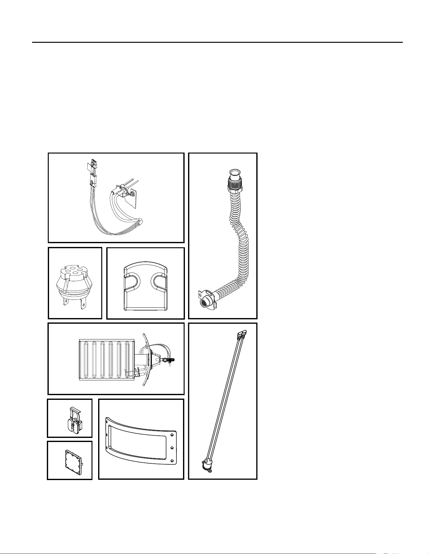
LISTED PARTS KITS AND ILLUSTRATIONS
Item 10: Flame Sense/Hot Surface Igniter Assembly.
Item 11: FV Sensor
Item 12: FV Sensor Bracket
Item 13: Burner door assembly (contains the manifold tube, gasket, manifold door, manifold component block with retainer clip,
and flame sensor/hot surface igniter assembly). Natural Gas.
Item 14: Manifold component block with retainer clip.
Item 15: Viewport.
Item 16: Burner door gasket.
Item 18: Flexible manifold tube.
ITEM 10
ITEM 13
ITEM 15
ITEM 16
ITEM 14
ITEM 18
ITEM 11
ITEM 12
ITEM 19
REPAIR PARTS
Copyright © 2023. A.O. Smith
All Rights Reserved
Printed on: 7/6/2023 9:40:13 AM CT