
SMALL APERTURE SERIES
SA4-66
INSTALLATION MANUAL

2
SMALL APERTURE SERIES SPEAKER
SA4-66
TABLE OF CONTENTS
2 Box Contents
2 Introduction
2 Important Safety Information
2 Preparation
3 Required Parts by Application
3 Drywall/Gypsum Install with Micro Trim Grille
6 Drywall/Gypsum Board Flush Trimless Grille
8 Solid Surface with Mirco Trim or
Flush Trimless Grille
11 Spacers Explained
12 Technical Specifications
13 Detailed Box Contents
15 Warranty
BOX CONTENTS*
SA4-66-COMPLETE-T | 93729
• SA4-66-ENC Speaker Enclosure | 93711
• SA4-66-MOD Speaker Module | 93710
• SA4-GRILLE-RND-KIT-T Round Micro Trim
Grille Kit | 93720
INTRODUCTION
The Sonance SA4-66 system is available as a complete
kit (93729) or in individual components. The complete
kit includes everything needed for installation in drywall
or other surfaces with a Micro Trim grille. For projects
with extended timelines, purchasing components
separately may be preferred to avoid storing shims,
speaker modules, and grilles on-site.
IMPORTANT: Read this section in its entirety before
attempting use of the speaker.
IMPORTANT SAFETY INSTRUCTIONS
Always follow these basic safety precautions when
using your speaker to reduce the risk of fire, electric
shock, and injury to people or objects.
1. Read all the safety and operating instructions
before operating the speaker and retain them for
future reference.
2. Adhere to all warnings and precautions listed on the
speaker and in the operating instructions.
3. Follow all operating instructions.
PREPARATION
Determine the required parts and pieces for your
application based on the Required Parts Chart on the
following page. After installing the SA4-66 Speaker
Enclosure, jump to the section within this document for
finishing instructions related to your specific application.
IMPORTANT: The Sonance SA4-66 speaker is installed
behind the ceiling surface during pre-construction
framing, or as a renovation or remodel installation.
Both installations will require drywall installation,
patching, mudding, and/or final finish to the surface.
The Sonance SA4-66 system is available as a complete
kit (93729) or in individual components. The kit includes
everything needed for installation in drywall or gypsum
with a Micro Trim grille. For projects with extended
timelines, purchasing components separately may be
preferred to avoid storing shims, speaker modules, and
grilles on-site.
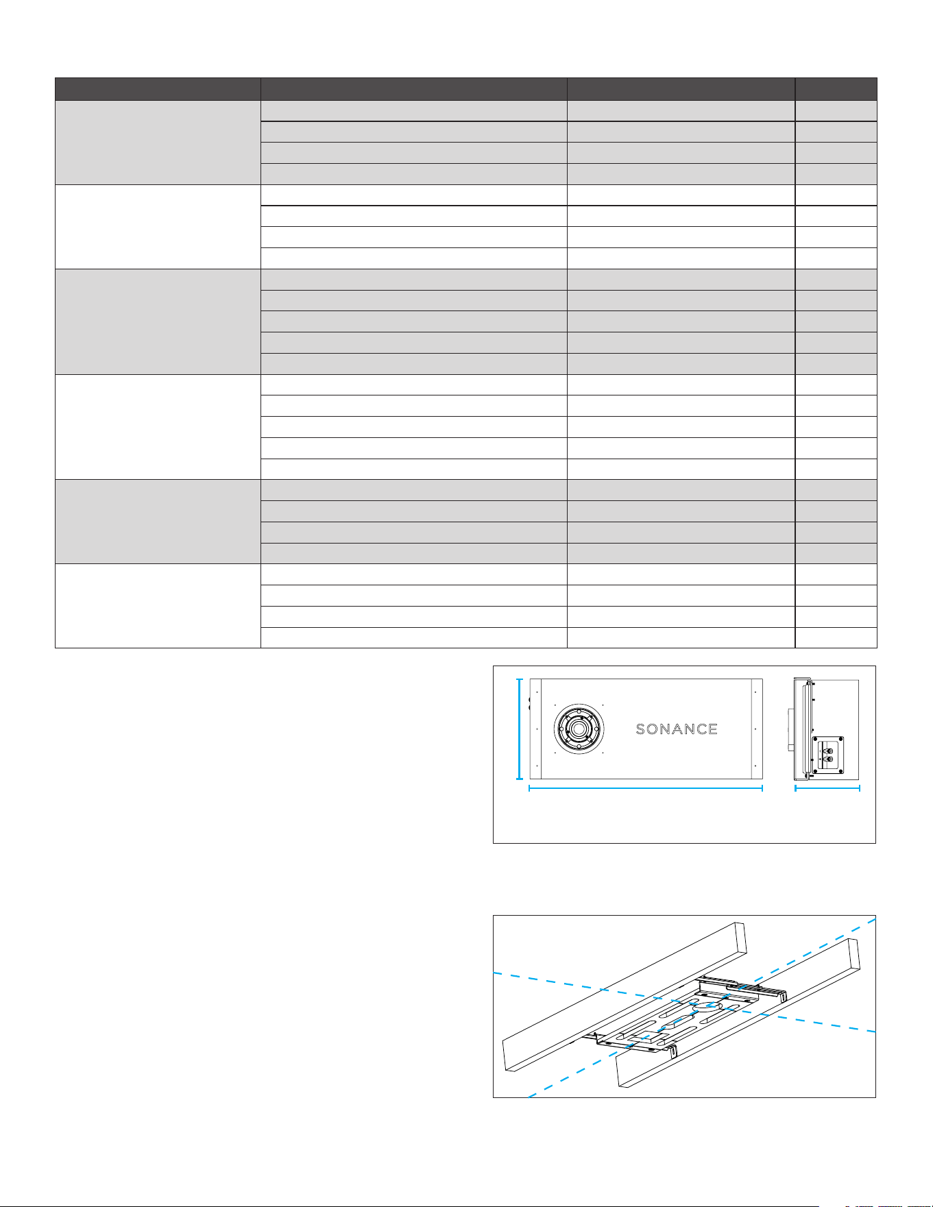
FRONT VIEWEND VIEW
*See page 13 for detailed list, replacement parts, and
installation accessories
• SA4-GRILLE-SQR-KIT-T Square Micro Trim
Grille Kit | 93721
• SA4 Micro Trim Spacer Kit for Micro Trim Finish into
Drywall or Solid Surface (Round and Square)
3
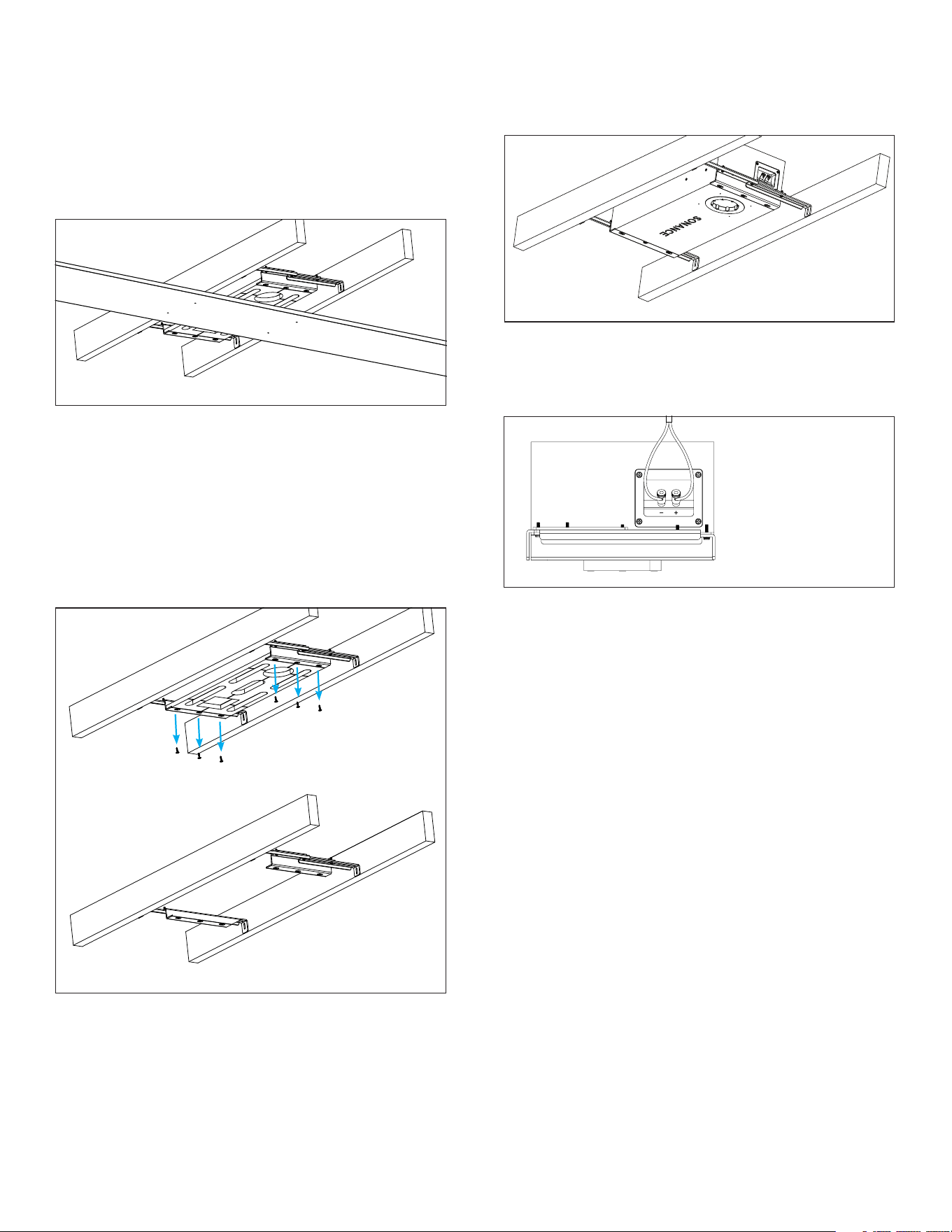
2. Use the provided SA4-66 alignment board to
position and preserve the speaker location (see
Figure 2).
DRYWALL/GYPSUM BOARD MICRO
TRIM GRILLE
INSTALLING THE SA4-66 SPEAKER ENCLOSURE
REQUIRED PARTS
• SA4-66 Speaker Enclosure | 93711
• SA4-66 Alignment Board (included)
• Six (6) Wood Screws (included)
• Laser Level (optional)
• Long Straight Edge (optional)
• Screwdriver or Drill
1. Select the desired location for your SA4-66
speaker, ensuring proper space to accommodate
the dimensions of the enclosure with desired
positioning of the opening for the module. Use a
laser level to ensure alignment with other speakers
and ceiling elements such as lighting (see Figure 1).
APPLICATION REQUIRED PARTS MODEL SKU
DRYWALL/GYPSUM BOARD,
MICRO TRIM,
ROUND
(Page 3)
SPEAKER ENCLOSURE SA4-66 ENC 93711
MICRO TRIM/SOLID SURFACE SPACER KIT SA4-SP-T-SS-KIT 93718
SPEAKER MODULE SA4-66 MOD 93710
MICRO TRIM ROUND GRILLE SA4-GRILLE-RND-KIT-T 93720
DRYWALL/GYPSUM BOARD,
MICRO TRIM,
SQUARE
(Page 3)
SPEAKER ENCLOSURE SA4-66 ENC 93711
MICRO TRIM/SOLID SURFACE SPACER KIT SA4-SP-T-SS-KIT 93718
SPEAKER MODULE SA4-66 MOD 93710
MICRO TRIM SQUARE GRILLE SA4-GRILLE-SQR-KIT-T 93721
DRYWALL/GYPSUM BOARD,
FLUSH,
TRIMLESS,
ROUND
SPEAKER ENCLOSURE SA4-66 ENC 93711
FLUSH DRYWALL SPACER KIT (optional) SA4-SP-FLUSH-GYP-KIT 93719
TRIM KIT SA4-TRIMKIT-FLUSH-GYP-RND 93712
SPEAKER MODULE SA4-66 MOD 93710
TRIMLESS ROUND GRILLE SA4-GRILLE-RND-NT 93725
DRYWALL/GYPSUM BOARD,
FLUSH,
TRIMLESS,
SQUARE
SPEAKER ENCLOSURE SA4-66 ENC 93711
FLUSH DRYWALL SPACER KIT (optional) SA4-SP-FLUSH-GYP-KIT 93719
TRIM KIT SA4-TRIMKIT-FLUSH-GYP-RND 93712
SPEAKER MODULE SA4-66 MOD 93710
TRIMLESS SQUARE GRILLE SA4-GRILLE-SQR-NT 93726
SOLID SURFACE,
FLUSH,
ROUND
(Begin install steps on page 7)
SPEAKER ENCLOSURE SA4-66 ENC 93711
MICRO TRIM/SOLID SURFACE SPACER KIT SA4-SP-T-SS-KIT 93718
SPEAKER MODULE SA4-66 MOD 93710
TRIMLESS ROUND GRILLE SA4-GRILLE-RND-NT 93725
SOLID SURFACE,
FLUSH,
SQUARE
(Begin install steps on page 7)
SPEAKER ENCLOSURE SA4-66 ENC 93711
MICRO TRIM/SOLID SURFACE SPACER KIT SA4-SP-T-SS-KIT 93718
SPEAKER MODULE SA4-66 MOD 93710
TRIMLESS SQUARE GRILLE SA4-GRILLE-SQR-NT 93726
22.95” (583mm) 6.38” (162mm)
9.88” (251mm)
Figure 2: Extend and
Adjust Brackets
Figure 1: Enclosure Dimensions
REQUIRED PARTS BY APPLICATION
3. Use a screwdriver to loosen the bracket on both
ends to make the alignment board adjustable within
the ceiling joist or stud bay.
4
4. Secure the bracket between the two joists using the
included wood screws.
5. Use a block of wood to level the bracket with the
joists on each side.
NOTE: The alignment board should not extend into
the room beyond the plane of the joists. You will use
spacers to account for surface depths in a later step.
Remove Screws from Bracket
Figure 6:
Connecting
Speaker Wire
Figure 3: Level the Alignment Board
6. Adjust the bracket positioning to align its cross
hairs with surrounding room lines and elements as
desired. If finishing with a square trim later, this will
be critical to achieve grille alignment (see Figure 2).
Note the module opening location on the joists.
7. Remove the screws on the front of the bracket,
three on each end, to remove the MDF bracket from
the bracket frame (see Figure 4). These screws can
be discarded.
8. Insert the SA4-66 speaker enclosure into position
behind the bracket frame, setting it in place with
the module opening facing out in the desired
orientation. Make sure that the lip of the enclosure
catches on the lip of each end of the bracket frame.
9. Secure the bracket frame to the speaker enclosure
with the provided new wood screws, three on each
end. Do not reuse the shorter screws removed from
INSTALLING THE SPACERS | FINISHING THE SURFACE
REQUIRED PARTS
• SA4-66 Spacers
1. Determine the surface depth and select the
appropriate spacers. Spacers may be stacked
together along with the included 1mm shims to
accommodate the required depth from the speaker
opening to the final drywall surface (see Figure 7).
2. Secure the Spacer Stack through the threaded
holes in the speaker enclosure opening using the
provided screws.
IMPORTANT: Connect the speaker module to the
enclosure opening to test for functionality BEFORE
installing drywall over the enclosure. Once tested,
remove the module and reserve for later (as outlined in
step 11 in previous section).
Figure 4: Bracket Frame
the bracket earlier. Adjust the positioning as needed
to retain the desired cross hair alignment. Check
enclosure opening location matches the location
noted on the joist in step 6 (see Figure 5).
10. Run speaker wire from the amplifier location to the
speaker location and connect the positive to the red
spring terminal and the negative to the black spring
terminal (see Figure 6).
Figure 5: Speaker
Enclosure in the Brackets
11. Temporarily connect the SA4-66-MOD Speaker
Module to the 2-pin connector in the speaker
opening and play source signal to the speaker to test
operation before proceeding to the finishing section.
Once verified, disconnect the speaker module from
the 2-pin connector and reserve the module for later.
Wood
5
Figure 10: Test
Grille Fit
Figure 11: Remove
Grille, Module, and
Aligner
4. Install drywall around the Space Saver.
5. Once the drywall panel installation and painting
process is complete and has had time to dry, keep
the spacers but discard the plastic Space Saver.
6. Install the SA4-66 Speaker Module and Stacked
Spacers:
INSTALLING THE SPEAKER MODULE AND GRILLE
REQUIRED PARTS
• SA4-66 Speaker Module | 93710
• SA4-66 Round Micro Trim Grille Kit | 93720 or
SA4-66 Square Micro Trim Grille Kit | 93721
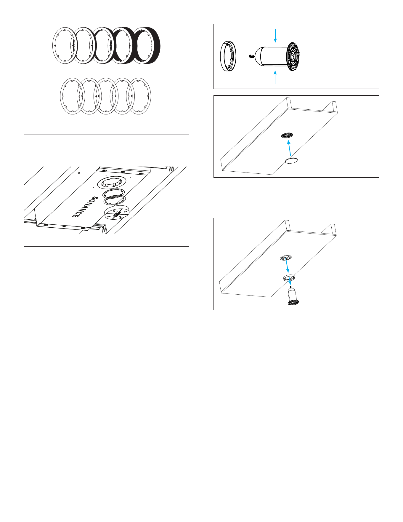
1. Position the aligner so that its flat side faces the
wire end of the speaker module, allowing the
rim of the module to slide into place within the
aligner’s raised lip. The flat side of the aligner
should be toward the wire end. Test fit the assembly
by securing it with two screws to the enclosure
opening (the aligner should be 0.125” (1/8”) proud
of the ceiling surface). Test the grille fit to verify
proper fit and spacing. If there are gaps between
the surface and the grille, remove the grille and
module/spacer assembly to adjust the spacers until
the correct spacing for perfect grille fit is achieved.
Figure 9: Test Fit
Grille and Aligner in
Prepared Opening
2. After the spacers have been adjusted as needed,
remove the module and grille aligner from the
enclosure. Keep the grille aligner and spacer stack
around the speaker module (see Figure 11).
3. Connect the 2-pin connector from the enclosure
opening to the 2-pin connector on the back of the
speaker module, including the aligner and spacer
stack. Make sure that the connector orientation is
correct. Insert the speaker module into the opening
and secure the speaker module to the enclosure
using four screws (see Figure 12).
4. After installing the speaker module, check for and
remove any cable obstructions inside the port.
• Do this by shining a flashlight into the port
openings that surround the installed speaker
module.
• Perform a full 360° check, closely inspecting the
entire length of the port inside the enclosure
around the entire perimeter of the port.
• Look for any area where the cable is bunched
up and potentially blocking the port.
• If any obstructions are found, use a long, thin
tool such as a flat blade screwdriver to push the
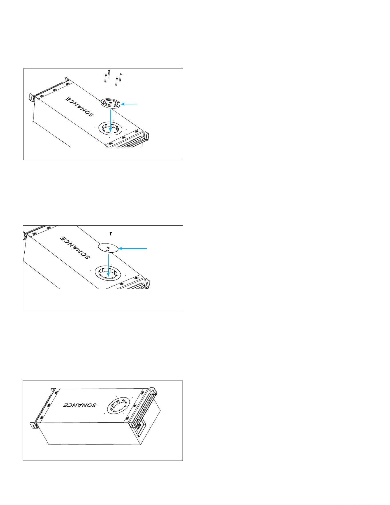
Figure 7: Wallboard Spacer Stacks
Figure 8: Space Saver and Spacers
1mm x 5
1/2”
Red
5/8”
Blue
5/8” +1/2”
Purple
5/8” +
5/8” Green
5/8” + 3/4”
Yellow
3. Secure the Space Saver to the stacked spacers
and shims to cover the speaker opening using the
provided screws (see Figure 8).
6
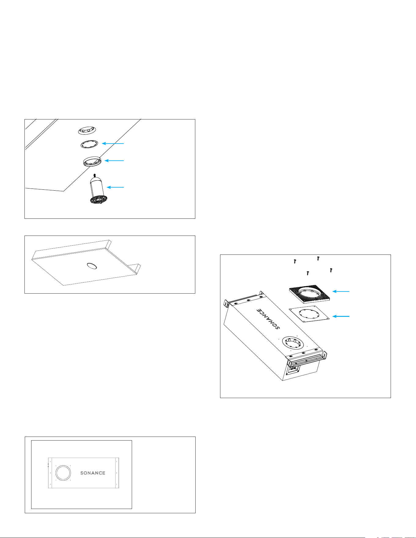
Figure 15: Stack the Mud Ring and Spacers
Figure 12: Insert Module and Secure
Figure 13: Secure Grille
6. Connect and play a source to the amplifier and enjoy!
Grille Aligner
Spacer(s)
Speaker Module
DRYWALL/GYPSUM BOARD FLUSH
TRIMLESS GRILLE
PREPARING THE SA4-66 ENCLOSURE
REQUIRED PARTS
• SA4-66 Speaker Enclosure | 93711
• SA4-66 Spacer Flush Gypsum Kit | 93719 (optional)
• SA4-66 Trim Flush Gypsum Kit Round | 93712 or
• SA4-66 Trim Flush Gypsum Kit Square | 93722
BEFORE YOU BEGIN
1. For precise flush alignment with drywall, it can be
helpful to place the enclosure on a table with the
ceiling materials nearby so that the appropriate
spacer thickness can be selected prior to enclosure
installation (see Figure 14).
cable obstruction further into the port until the
port is 100% clear.
• Best practice is to push the screwdriver into
every opening around the port and keep
pushing until the cable is cleared out of the way.
• After this process, double check with a
flashlight to confirm no port obstructions.
5. Insert the round or square Micro Trim Grille over the
grille aligner (see Figure 13).
2. Determine appropriate spacers for surface thickness.
Refer to page 11, SPACERS EXPLAINED to help
define the spacers required for your application.
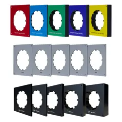
AVAILABLE ACCESSORY KITS
SA4-SP-FLUSH-GYP-KIT | 93719
• Wallboard Spacers (colorful spacers, marked for
wallboard spec)
• Dimensional Spacers (black spacers, marked with
physical thickness)
SA4-TRIMKIT-FLUSH-GYP-RND | 93712
• Round Mud Ring Assembly
• Wallboard Spacers (colorful spacers, marked for
wallboard spec)
SA4-TRIMKIT-FLUSH-GYP-SQR | 93722
• Square Mud Ring Assembly
• Wallboard Spacers (colorful spacers, marked for
wallboard spec)
NOTE: Spacers can be used interchangeably for either
round or square applications
3. Stack the appropriate spacers with either a round or
square mud ring (see Figure 15).
4. Align the inner holes with the threaded inserts in the
enclosure.
Figure 14:
Preparing the
Enclosure
NOTE: Round and square applications require dierent
mud rings, select accordingly.
5. Use screws of the correct length for the surface
thickness to insert the plastic paint shield into the
center of the mud ring.
• Align its four holes with the spacer, mud ring,
and threaded inserts in the enclosure.
• Secure the assembly with screws of the correct
length for the surface thickness through the
inner threaded holes (see Figure 16).
Spacers
Mud Ring
7
1. Select the desired location for your SA4-66
speaker, ensuring proper space to accommodate
the dimensions of the enclosure with desired
positioning of the opening for the module. Use a
laser level to ensure alignment with other speakers
and ceiling elements such as lighting (see Figure 1).
2. Use the provided SA4-66 bracket to position and
preserve the speaker location (see Figure 2).
3. Use a screwdriver to loosen the bracket on both
ends to make the bracket adjustable within the
ceiling joist or stud bay.
4. Secure the bracket between the two joists using the
included wood screws.
5. Use a block of wood to level the bracket with the
joists on each side (see Figure 3).
NOTE: The bracket should not extend into the room
beyond the plane of the joists. The spacers will account
for surface depths.
6. Adjust the bracket positioning to align its cross
hairs with surrounding room lines and elements as
desired. If finishing with a square trim later, this will
be critical to achieve grille alignment (see Figure 2).
Mark the module opening location on the joists to
remember the correct speaker orientation later.
7. Remove the screws on the front of the bracket,
three on each end, to remove the MDF bracket from
the bracket frame (see Figure 4). These screws can
be discarded.
8. Insert the SA4-66 speaker enclosure into position
behind the bracket frame, setting it in place with
the module opening facing out in the desired
orientation. Make sure that the lip of the enclosure
catches on the lip of each end of the bracket frame.
9. Secure the bracket frame to the speaker enclosure
with the new wood screws provided, three on each
end. Do not reuse the shorter screws removed from
the bracket earlier. Adjust the positioning as needed
to retain the desired cross hair alignment. Check
enclosure opening location matches the location
noted on the joist (see Figure 5).
10. Run speaker wire from the amplifier location to the
speaker location and connect the positive to the red
spring terminal and the negative to the black spring
terminal (see Figure 6).
11. Remove the four screws holding the paint shield
(with sanding shield intact) and reserve the shields
and screws to allow for speaker module testing.
IMPORTANT: Connect the speaker module with the
2-pin connector from the enclosure opening and test
for functionality by playing signal from the amplifier
and a source. Then power the amplifier o before
disconnecting the module. Replace paint shield and
sanding shield into the opening using the four reserved
screws from step 11.
Figure 16: Install the Plastic Paint Shield
Figure 17: Install the Metal Sanding Shield and
Secure the Mud Ring Assembly to the Enclosure
Figure 18: Attach the Sanding Shield
6. Fasten the mud ring at all four corners using the
four included wood screws (see Figure 15).
• The enclosure has pilot holes to aid this process.
• Ensure the screws extend at least 1/2” (12mm)
into the enclosure for a firm hold.
7. Place the metal sanding shield on top of the
secured plastic paint shield.
• Secure it to the paint shield using the included
screw (see Figure 18).
• Tip: Cover the keyhole in the sanding shield with
painter’s tape to prevent drywall compound
from blocking it.
INSTALLING THE SA4-66 SPEAKER ENCLOSURE
REQUIRED PARTS
• SA4-66 Speaker Enclosure | 93711
• SA4-66 Bracket (included)
• Six (6) Wood Screws (included)
• Laser Level (optional)
• Long Straight Edge (optional)
• Screwdriver or Drill
The enclosure and mud ring assembly is now prepared
for installation into the surface location.
Paint Shield
Sanding
Shield
8
3. Insert the round or square Trimless Grille into
position over the module.
4. Connect and play a source to the amplifier and enjoy!
SOLID SURFACE WITH MICRO TRIM
OR FLUSH TRIMLESS GRILLE
PREPARING THE SA4-66 SPEAKER ENCLOSURE
REQUIRED PARTS
• SA4-66 Speaker Enclosure | 93711
• SA4-66 Micro Trim/Solid Surface Spacer Kit |
93718
• SA4-66 Round Micro Trim Grille Kit | 93720
or SA4-66 Square Micro Trim Grille Kit | 93721
or SA4 Trimless Grille Round | 93725 or SA4
Trimless Grille Square | 93726
• SA4-66 Speaker Module | 93710
INSTALLING THE SPACERS | FINISHING THE SURFACE
1. Install drywall as usual, ensuring proper taping and
mudding.
• TIP: Use mesh joint tape around all four sides of
the mud ring where it meets the drywall.
• Allow drywall to dry completely before sanding.
2. Sand the surface until a small gap appears around
the perimeter of the sanding shield.
• Remove the center screw from the sanding
shield.
• Clear the keyhole in the sanding shield using a
drywall screw or remove the tape.
• Insert a drywall screw into the keyhole and use
pliers to pull firmly and remove the sanding
shield.
3. Ensure the paint shield is in place before applying
paint.
• Roll paint directly over the opening.
• TIP: Before the paint dries, clean the inside
edges of the mud ring with a dry 1” mini roller or
dry paintbrush to prevent buildup or drips.
4. Once the paint is completely dry, remove the paint
shield by unscrewing the two securing screws.
INSTALLING THE SPEAKER MODULE AND GRILLE
REQUIRED PARTS
• SA4 Trimless Grille Round | 93725 or SA4
Trimless Grille Square | 93726
• SA4-66 Speaker Module | 93710
1. Connect the 2-pin connector from the enclosure
opening to the 2-pin connector on the back of
the speaker module. Make sure that the connector
orientation is correct. Insert the speaker module into
the opening and secure the speaker module to the
enclosure using four screws.
2. After installing the speaker module, check for and
remove any cable obstructions inside the port.
• Do this by shining a flashlight into the port
openings that surround the installed speaker
module.
• Perform a full 360° check, closely inspecting the
entire length of the port inside the enclosure
around the entire perimeter of the port.
• Look for any area where the cable is bunched
up and potentially blocking the port.
• If obstructions are found, use a long, thin tool (a
flat blade screwdriver) to push the obstruction
further into the port until the port is 100% clear.
• Best practice is to push the screwdriver into
every opening around the port and keep
pushing until the cable is cleared out of the way.
• After this process, double check with a flashlight
to confirm no port obstructions.
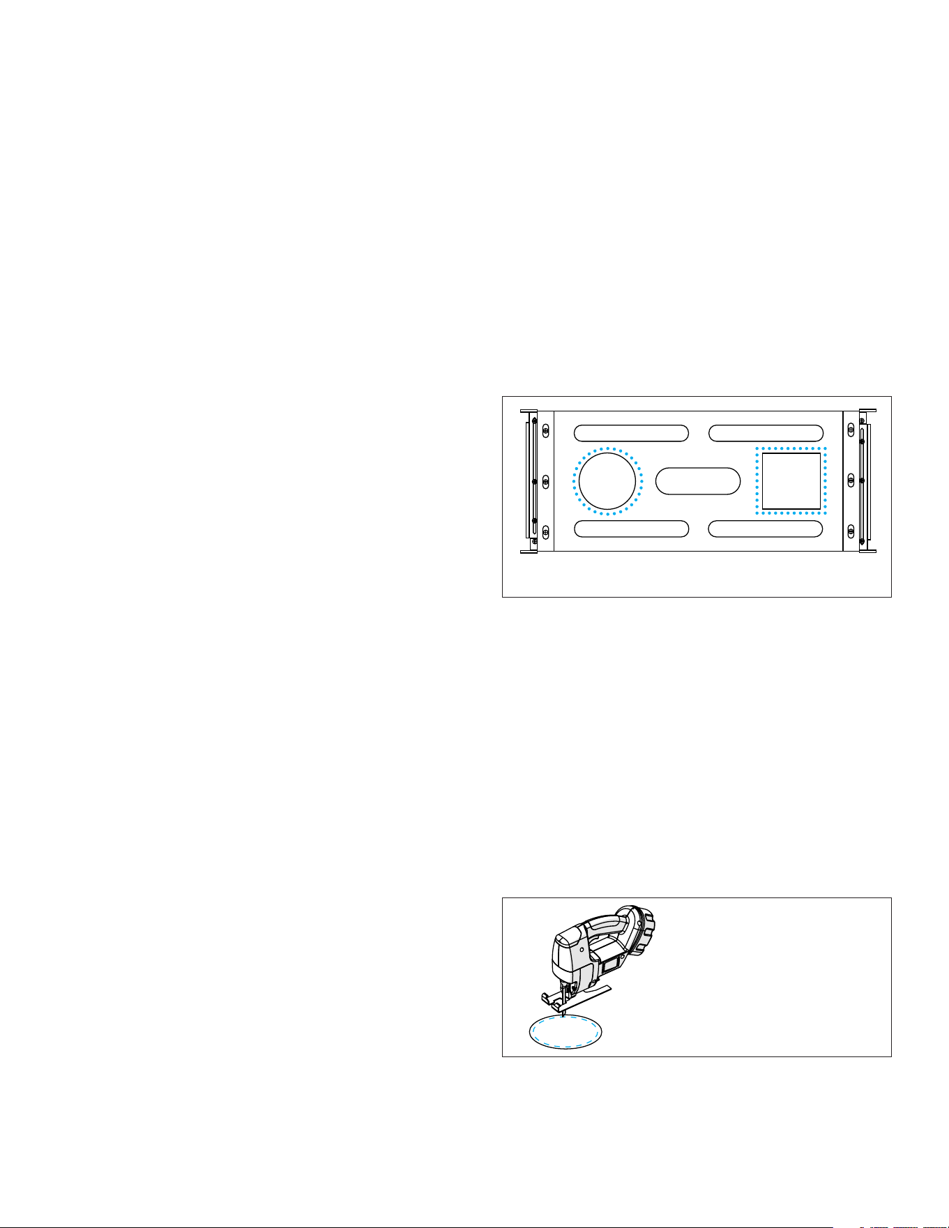
Figure 19: Alignment Board as Round
or Square Router Template
BEFORE YOU BEGIN
1. For precise flush alignment with solid surfaces, it is
helpful to place the enclosure on a table with the
ceiling materials nearby so that the appropriate
spacer thickness can be selected.
2. Use the Alignment Board included with the
enclosure as the routing template; it has cutout
templates for both round and square grilles.
3. Use the square or round template to mark an
outline on the solid surface material in the desired
location of the grille opening.
4. Use a drill and jigsaw to cut a hole through the
material on the inside of the marking, leaving about
1/8” (3mm) border around the edge.
Figure 20: Pre-cut with Jigsaw
IMPORTANT: Leave a 1/8”
(3mm) gap inside the
cutout marking.
5. Ax the Alignment Board to the solid surface
material using double sided tape or clamps, aligning
it precisely with the marking made earlier.
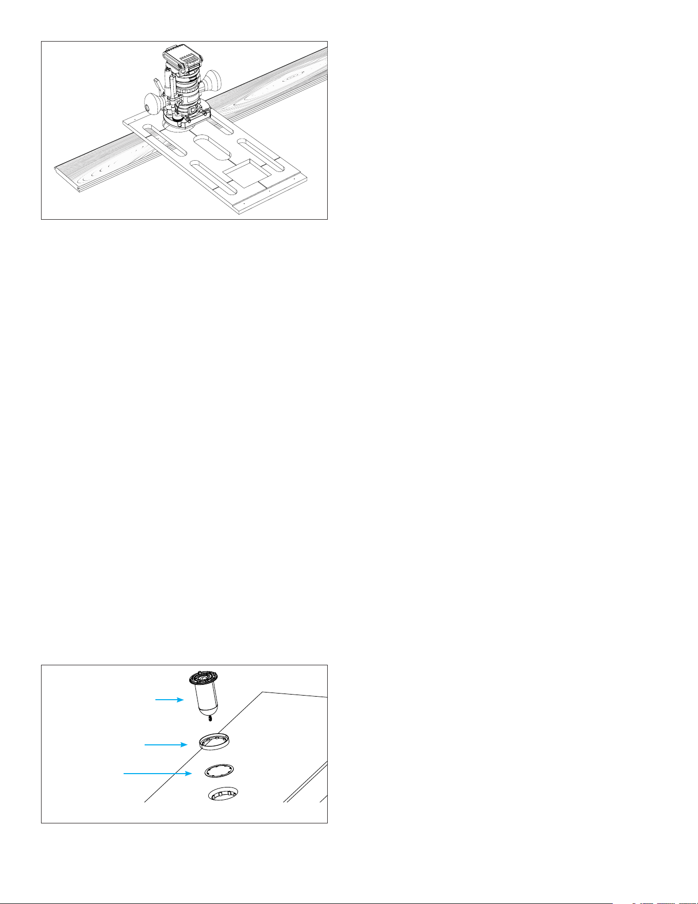
6. Use a Flush Trim Router Bit to clean up the cutout,
allowing its bearing edge to ride along the Alignment
Board template as a guide.
9
INSTALLING THE SA4-66 SPEAKER ENCLOSURE
REQUIRED PARTS
• SA4-66 Speaker Enclosure | 93711
• SA4-66 Bracket (included)
• Six (6) Wood Screws (included)
• Laser Level (optional)
• Long Straight Edge (optional)
• Screwdriver or Drill
Optionally install the selected spacers, shims, and space
saver prior to enclosure installation to help reserve
and identify the speaker locations in the ceiling. For
some installation types, this may interfere with ceiling
installation. Check with your install team first. If the
spacers, shims, and/or space savers will interfere with
the ceiling installation, remove them from the enclosure
and install later.
1. Select the desired location for your SA4-66
speaker. Ensure proper space to accommodate
the dimensions of the enclosure with desired
positioning of the opening for the module. Use a
laser level to ensure alignment with other speakers
and ceiling elements such as lighting (see Figure 1).
2. Use the provided SA4-66 bracket to position and
preserve the speaker location (see Figure 2).
3. Use a screwdriver to loosen the bracket on both
ends to make the bracket adjustable within the
ceiling joist or stud bay.
4. Secure the bracket between the two joists using the
included wood screws.
5. Use a long level or straight edge to level the bracket
with the joists on each side, ensuring that the
bracket is even (see Figure 3).
NOTE: The bracket should not extend into the room
beyond the plane of the joists. The spacers installed
earlier account for surface depths.
6. Adjust the bracket positioning to align its cross
hairs with surrounding room lines and elements as
desired. If finishing with a square trim later, this will
be critical to achieve grille alignment (see Figure 2).
Mark the module opening location on the joists to
remember the correct speaker orientation later.
7. Remove the screws on the front of the bracket,
three on each end, to remove the MDF bracket from
the bracket frame (see Figure 4). These screws can
be discarded.
8. Insert the SA4-66 Speaker Enclosure into position
behind the bracket frame, setting it in place with
the module opening facing out in the desired
orientation. Make sure that the lip of the enclosure
catches on the lip of each end of the bracket frame.
9. Secure the bracket frame to the speaker enclosure
with the new wood screws provided, three on each
end. Do not reuse the shorter screws removed from
the bracket earlier. Adjust the positioning as needed
Figure 22: Spacer Stack
7. Select spacers based on surface thickness. You may
need to stack spacers to achieve the perfect flush
alignment.
• Refer to the Spacers Explained section for details.
• Dimensional Spacers work best for solid surfaces.
RECOMMENDED ACCESSORY KIT:
SA4-SP-T-SS-KIT | 93718
• Wallboard Spacers
• Dimensional Spacers
NOTE: Spacers are compatible for both round and
square grille applications.
8. Test fit the spacers, speaker module, and grille. For
Micro Trim installations, place the grille aligner
around the speaker module.
9. Put the enclosure on a table with the opening facing
up. Align the cutout on the solid surface material
with the enclosure opening and place it on the
enclosure.
10. Stack the appropriate spacers and shims into the
opening, add the speaker module, and grille. For
Solid Surface installations using a micro trim grille,
be sure to add the grille aligner behind the speaker
module before adding to the opening (see Figure 22).
11. Adjust the spacer stack as needed until the grille is
perfectly flush with the solid surface material that will
be used in the ceiling.
Grille Aligner
Spacer(s)
Speaker Module
NOTE: Grille aligner is only applicable when using Micro
Trim grilles. Omit this piece if installing Trimless grilles.
IMPORTANT: Use Flush Trim Router bit.
Figure 21: Flush Trim Router

10
• Perform a full 360° check, closely inspecting the
entire length of the port inside the enclosure
around the entire perimeter of the port.
• Look for any area where the cable is bunched up
and potentially blocking the port.
• If any obstructions are found, use a long, thin
tool such as a flat blade screwdriver to push the
cable obstruction further into the port until the
port is 100% clear.
• Best practice is to push the screwdriver
intoevery opening around the port and keep
pushing until the cable is cleared out of the way.
• After this process, double check with a flashlight
to confirm no port obstructions.
7. Insert the round or square Micro Trim or Trimless
Grille into position over the module.
8. Connect and play a source to the amplifier and enjoy!
to retain the desired cross hair alignment. Check
enclosure opening location matches the location
noted on the joist in step 6.
10. Run speaker wire from the amplifier location to the
speaker location and connect the positive to the red
spring terminal and the negative to the black spring
terminal (see Figure 5).
IMPORTANT: Connect the speaker module to the
enclosure opening to test for functionality BEFORE
installing the ceiling surface over the enclosure. Once
tested, remove the module and reserve for later.
INSTALLING THE SPACERS | FINISHING THE SURFACE
1. Install the solid surface ceiling material over the
speaker enclosure making sure to align all openings
in the solid surface material precisely with the
speaker enclosure opening locations.
2. If spacers were removed earlier, reinstall them.
INSTALLING THE SPEAKER MODULE AND GRILLE
REQUIRED PARTS
• SA4-66 Round Micro Trim Grille Kit | 93720
or SA4-66 Square Micro Trim Grille Kit | 93721
or SA4 Trimless Grille Round | 93725 or SA4
Trimless Grille Square | 93726
• SA4-66 Speaker Module | 93710
1. For Flush installations, skip to the next step. For
Micro Trim installations, place the round or square
grille aligner around the speaker module. Refer back
to page 5, step 1 of the section titled INSTALLING
THE SPEAKER MODULE AND GRILLE for detailed
instructions.
2. Place the speaker module into the enclosure
opening to test fit the assembly by securing it with
two screws. Test the grille fit. If the grille will not
stay on or if there is a gap between the installation
surface and the grille, spacers and shims will need
to be added or removed until the grille fit is perfect.
3. After the spacers have been adjusted as needed,
remove the grille, speaker module, and grille aligner
(if applicable) from the enclosure.
4. For Flush installations, skip to the next step. For
Micro Trim installations, keep the grille aligner
around the module.
5. Connect the 2-pin connector from the enclosure
opening to the 2-pin connector on the back of
the speaker module. Make sure that the connector
orientation is correct. Insert the speaker module
into the opening and secure the speaker module to
the enclosure using four screws.
6. After installing the speaker module, check for and
remove any cable obstructions inside the port.
• Do this by shining a flashlight into the port
openings that surround the installed speaker
module.
11
SURFACE
MICRO TRIM INSTALLATION SPACERS
(93718 SPACER KIT)
FLUSH TRIMLESS INSTALLATION SPACERS
(93719 SPACER KIT, 93712 ROUND TRIM KIT,
OR 93722 SQUARE TRIM KIT)
1/2” Drywall 1/2” Wallboard Spacer (Red) 1/2” Wallboard Spacer (Red)
5/8” Drywall 5/8” Wallboard Spacer (Blue) 5/8” Wallboard Spacer (Blue)
5/8” + 1/2” 5/8” + 1/2” Wallboard Spacer (Purple) 5/8” + 1/2” Wallboard Spacer (Purple)
5/8” + 5/8” 5/8” + 5/8” Wallboard Spacer (Green) 5/8” + 5/8” Wallboard Spacer (Green)
5/8” + 3/4” 5/8” + 3/4” Wallboard Spacer (Yellow) 5/8” + 3/4” Wallboard Spacer (Yellow)
1/2” Drywall + 1”
1/2” Wallboard Spacer (Red) +
1” Dimensional Spacer (Black)
1/2” Wallboard Spacer (Red) +
1” Dimensional Spacer (Black)
5/8” Drywall + 0.25”
5/8” Wallboard Spacer (Blue) +
0.25” Dimensional Spacer (Black)
5/8” Wallboard Spacer (Blue) +
0.25” Dimensional Spacer (Black)
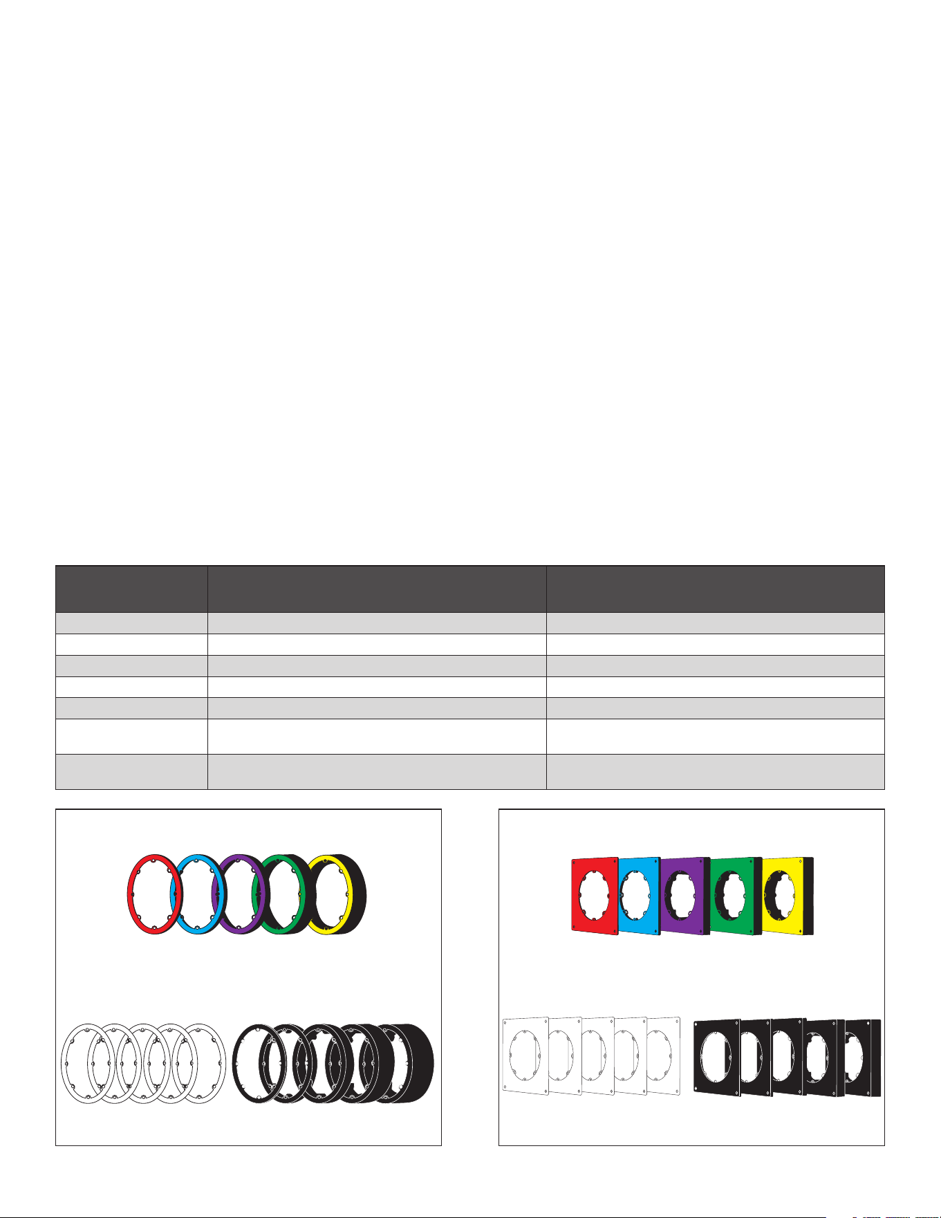
Small Aperture Spacers are used to align the speaker
module to the installation surface for a seamless and
gapless grille finish that blends into the plane of the
ceiling. This is especially important for flush installations.
There are two types of spacers available for Sonance SA:
Wallboard Spacers and Dimensional Spacers.
WALLBOARD SPACERS
Wallboard Spacers are conveniently sized so that when
used properly, the final speaker module height aligns
with common wallboard thicknesses. Each Wallboard
Spacer is color-coded and labeled with the wallboard
panel thickness it is intended to be used with. For
instance, the blue spacer labeled “For 5/8” Wallboard”
should be used with 5/8” wallboard. Some of the
Wallboard Spacers are to be used with various stacks
of wallboard (sometimes referred to in the trade as
“double-rock”). For instance, the green spacer labeled
“For 5/8” + 5/8” Wallboard” should be used when two
layers of 5/8” wallboard are installed. If the speaker
module height does not perfectly match the ceiling
surface, multiple spacers can be stacked and/or the
included white 1mm shims may be used to fine-tune the
speaker module height. Note that the actual thickness
of the Wallboard Spacers are arbitrary dimensions
SPACERS EXPLAINED
1mm x 5
1/2”
Red
5/8”
Blue
5/8” +1/2”
Purple
5/8” + 5/8”
Green
5/8” + 3/4”
Yellow
0.125”
3.2mm
0.25”
6.4mm
0.5”
12.7mm
1”
25.4mm
1.5”
38.1mm
DIMENSIONAL SPACERS
(labeled for actual dimension)
SPACER SHIMS
MICRO TRIM WALLBOARD SPACERS
(calculated to wallboard dimension)
1mm x 5
1/2”
Red
5/8”
Blue
5/8” +1/2”
Purple
5/8” + 5/8”
Green
5/8” + 3/4”
Yellow
0.125”
3.2mm
0.25”
6.4mm
0.5”
12.7mm
1”
25.4mm
1.5”
38.1mm
DIMENSIONAL SPACERS
(labeled for actual dimension)
SPACER SHIMS
FLUSH WALLBOARD SPACERS
(calculated to wallboard dimension)
that are meant to be used with common ceiling panel
thicknesses. If a specific dimensional thickness is
required, which is common for solid surface installations
such as tongue and groove wood ceilings, the Small
Aperture Dimensional Spacers are an alternative
solution.
DIMENSIONAL SPACERS
Dimensional Spacers are made to precise thicknesses as
specified on the face of the spacer. These spacers are
black in color with the thickness dimensions labeled in
both imperial and metric. If the speaker module height
does not perfectly match the ceiling surface, multiple
spacers can be stacked and/or the included white 1mm
shims may be used to fine-tune the speaker module
height.
Wallboard Spacers and Dimensional Spacers may be
mixed and matched and stacked in any combination.
However, regardless of which spacer type is used and
how they are stacked, the total spacer thickness must
not exceed 2” (50mm); otherwise, the performance of
the product will be compromised.
NOTE: Spacers for Flush Drywall installations are
square in shape. Spacers for all other installation
types are circular. Although there is no dierence in
functionality, they must not be interchanged.

12
SA4-66 Complete Kit Micro Trim
SKU 93729
UOM Each
Wide Bandwidth Driver 2” (50mm) Aluminum cone, rubber surround
Woofer 6.5” (165mm) Aluminum cone, rubber surround
Frequency Response 45Hz–22kHz +/-3dB
Frequency Range 35Hz–25kHz +/-10dB
Impedance 8 ohms nominal; 6 ohms minimum
Power Handling 5 watts minimum to 125 watts maximum
Sensitivity 82dB SPL
Overload Protection Two independent, self-resetting poly switches
Enclosure Only (WxHxD)) 22.95” x 10.2” x 6.38” (583mm x 258.5mm x 162mm)
Enclosure With Bracket (WxHxD) 25.9” x 10.2” x 6.38” (658mm x 258.5mm x 162mm)
Minimum Installation Width 10.2” (258.5mm)
Maximum Installation Width 25.5” (649.1mm)
Flush Round Grille (Dia) 4.02” (102mm)
Flush Square Grille (HxW) 4.02” x 4.02” (102mm x 102mm)
Micro Trim Round Grille (Dia) 4.62” (117.4mm)
Micro Trim Square Grille (HxW) 4.62” X 4.62 (117.4mm x 117.4mm)
Enclosure Weight 19.73 lbs (8.95kg)
Module Weight 0.8 lbs (0.35kg)
Complete Kit (SKU 93729) Shipping Weight 34.17lbs (15.5kg)
TECHNICAL SPECIFICATIONS

13
BOX CONTENTS
• SA4-66-ENC Speaker Enclosure | 93711
(1) SA4-66 Speaker Enclosure
(1) 4” Round Space Saver
(1) 4” Square Space Saver
(6) Flat Head Philips Screws (30mm)
• SA4-66-MOD Speaker Module | 93710
(1) SA4-66 Speaker Module
(6) Flat Head Philips Screws (30mm)
(6) Flat Head Philips Screws (50mm)
(6) Flat Head Philips Screws (65mm)
• SA4-GRILLE-RND-KIT-T Round Micro Trim
Grille Kit | 93720
(1) 4” Round Micro Trim Grille
(1) 4” Round Micro Trim Grille Aligner
• SA4-GRILLE-SQR-KIT-T Square Micro Trim
Grille Kit | 93721
(1) 4” Square Micro Trim Grille
(1) 4” Square Micro Trim Grille Aligner
• SA4-SP-T-SS-KIT Spacer Kit for Micro Trim or Solid
Surface (Round and Square)
(1) 1/2” USA Drywall Spacer (red)
(1) 5/8” USA Drywall Spacer (blue)
(1) 5/8” Drywall + 5/8” Drywall Spacer (green)
(1) 5/8” Drywall + 1/2” Plywood Spacer (purple)
(1) 5/8” Drywall + 3/4” Plywood Spacer (yellow)
(5) 1mm Depth Shim (white)
(6) Flat Head Philips Screws (30mm)
(6) Flat Head Philips Screws (50mm)
(6) Flat Head Philips Screws (65mm)
REPLACEMENT/INSTALLATION
ACCESSORIES (SOLD SEPARATELY)
• SA4-66-ENC | 93711
(1) SA4-66 Speaker Enclosure
(1) 4” Round Space Saver
(1) 4” Square Space Saver
(6) Flat Head Philips Screws (30mm)
• SA4-66-MOD | 93710
(1) SA4-66 Speaker Module
(6) Flat Head Philips Screws (30mm)
(6) Flat Head Philips Screws (50mm)
(6) Flat Head Philips Screws (65mm)
• SA4 Replacement Space Saver Kit
(Round and Square) | 93728
(6) Flat Head Philips Screws (30mm)
(1) 4” Round Space Saver
(1) 4” Square Space Saver
• SA4-SP-T-SS-KIT Spacer Kit for Micro Trim or Solid
Surface (Round and Square) | 93718
(1) 1/2” USA Drywall Spacer (red)
(1) 5/8” USA Drywall Spacer (blue)
(1) 5/8” Drywall + 5/8” Drywall Spacer (green)
(1) 5/8” Drywall + 1/2” Plywood Spacer (purple)
(1) 5/8” Drywall + 3/4” Plywood Spacer (yellow)
(5) 1mm Depth Shim (white)
(1) 0.125” (3.2mm) Depth Spacer (black)
(1) 0.25” (6.4mm) Depth Spacer (black)
(1) 0.5” (12.7mm) Depth Spacer (black)
(1) 1” (25.4mm) Depth Spacer (black)
(1) 1.5” (38.1mm) Depth Spacer (black)
(6) Flat Head Philips Screws (30mm)
(6) Flat Head Philips Screws (50mm)
(6) Flat Head Philips Screws (65mm)
• SA4-SP-GYP-FLUSH-KIT Flush Drywall Spacer Kit
(Round and Square) | 93719
(1) 1/2” USA Drywall Spacer (red)
(1) 5/8” USA Drywall Spacer (blue)
(1) 5/8” Drywall + 5/8” Drywall Spacer (green)
(1) 5/8” Drywall + 1/2” Plywood Spacer (purple)
(1) 5/8” Drywall + 3/4” Plywood Spacer (yellow)
(5) 1mm Depth Shim (white)
(1) 0.125” (3.2mm) Depth Spacer (black)
(1) 0.25” (6.4mm) Depth Spacer (black)
(1) 0.5” (12.7mm) Depth Spacer (black)
(1) 1” (25.4mm) Depth Spacer (black)
(1) 1.5” (38.1mm) Depth Spacer (black)
(6) Flat Head Philips Screws (30mm)
(6) Flat Head Philips Screws (50mm)
(6) Flat Head Philips Screws (65mm)

14
• SA4-TRIMKIT-FLUSH-GYP-RND Flush Drywall Trim
Kit (Round) | 93712
(1) 1/2” USA Drywall Spacer (red)
(1) 5/8” USA Drywall Spacer (blue)
(1) 5/8” Drywall + 5/8” Drywall Spacer (green)
(1) 5/8” Drywall + 1/2” Plywood Spacer (purple)
(1) 5/8” Drywall + 3/4” Plywood Spacer (yellow)
(5) 1mm Depth Shim (white)
(1) Mud Ring for Round Flush Trim
(1) Round Paint Shield
(1) Round Sanding Shield
(10) Flat Head Philips Screws (30mm)
(10) Flat Head Philips Screws (50mm)
(10) Flat Head Philips Screws (65mm)
(6) #6 Philips #2 Screws (35mm)
(6) #6 Philips #2 Screws (55mm)
(6) #6 Philips #2 Screws (70mm)
(1) #6 Philips #2 Screws (16mm)
• SA4-TRIMKIT-FLUSH-GYP-SQR Flush Drywall Trim
Kit (Square) | 93722
(1) 1/2” USA Drywall Spacer (red)
(1) 5/8” USA Drywall Spacer (blue)
(1) 5/8” Drywall + 5/8” Drywall Spacer (green)
(1) 5/8” Drywall + 1/2” Plywood Spacer (purple)
(1) 5/8” Drywall + 3/4” Plywood Spacer (yellow)
(5) 1mm Depth Shim (white)
(1) Mud Ring for Square Flush Trim
(1) Square Paint Shield
(1) Square Sanding Shield
(10) Flat Head Philips Screws (30mm)
(10) Flat Head Philips Screws (50mm)
(10) Flat Head Philips Screws (65mm)
(6) #6 Philips #2 Screws (35mm)
(6) #6 Philips #2 Screws (55mm)
(6) #6 Philips #2 Screws (70mm)
(1) #6 Philips #2 Screws (16mm)
• SA4-GRILLE-RND-KIT-T Micro Trim Grille Kit
(Round) | 93720
(1) 4” Round Micro Trim Grille
(1) 4” Round Micro Trim Grille Aligner
• SA4-GRILLE-SQR-KIT-T Micro Trim Grille Kit
(Square) | 93721
(1) 4” Square Micro Trim Grille
(1) 4” Square Micro Trim Grille Aligner
• SA4-GRILLE-RND-T | 92723
(1) 4” Micro Trim Round Grille Only
• SA4-GRILLE-SQR-T | 92724
(1) 4” Micro Trim Square Grille Only
• SA4-GRILLE-RND-NT| 93725
(1) 4” Trimless Round Grille Only
• SA4-GRILLE-SQR-NT| 92726
(1) 4” Trimless Square Grille Only

15
©2025 Sonance. All rights reserved. Sonance is a registered trademark of Dana Innovations. Due to continuous product improvement, all features and
specifications are subject to change without notice. For the latest Sonance product specification information visit our website: www.sonance.com
SONANCE • 991 Calle Amanecer • San Clemente, CA 92673 USA • PHONE: (949) 492-7777
07.21.2025
LIMITED FIFTEEN (15) YEAR WARRANTY
Sonance warrants to the first end-user purchaser that this Sonance-brand product (“Product”), when purchased from an authorized
Sonance Dealer/Distributor, will be free from defective workmanship and materials for fifteen (15) years, of the Product, except for the
grille, which is warranted for five (5) years. Sonance will at its option and expense either repair the defect or replace the Product with a
new or remanufactured Product or a reasonable equivalent.
EXCLUSIONS: TO THE EXTENT PERMITTED BY LAW, THE WARRANTY SET FORTH ABOVE IS IN LIEU OF, AND EXCLUSIVE OF, ALL
OTHER WARRANTIES, EXPRESS OR IMPLIED, AND IS THE SOLE AND EXCLUSIVE WARRANTY PROVIDED BY SONANCE. ALL OTHER
EXPRESS AND IMPLIED WARRANTIES, INCLUDING THE IMPLIED WARRANTIES OF MERCHANTABILITY, IMPLIED WARRANTY OF
FITNESS FOR USE, AND IMPLIED WARRANTY OF FITNESS FOR A PARTICULAR PURPOSE ARE SPECIFICALLY EXCLUDED. NO ONE
IS AUTHORIZED TO MAKE OR MODIFY ANY WARRANTIES ON BEHALF OF SONANCE.
The warranty stated above is the sole and exclusive remedy and Sonance’s performance shall constitute full and final satisfaction of all
obligations, liabilities and claims with respect to the Product.
IN ANY EVENT, SONANCE SHALL NOT BE LIABLE FOR CONSEQUENTIAL, INCIDENTAL, ECONOMIC, PROPERTY, BODILY INJURY, OR
PERSONAL INJURY DAMAGES ARISING FROM THE PRODUCT, ANY BREACH OF THIS WARRANTY OR OTHERWISE.
This warranty statement gives you specific legal rights, and you may have other rights which vary from state to state. Some states do
not allow the exclusion of implied warranties or limitations of remedies, so the above exclusions and limitations may not apply. If your
state does not allow disclaimer of implied warranties, the duration of such implied warranties is limited to period of Sonance’s express
warranty.
Your Product Model and Description: Sonance Small Aperture SA4-66 Speaker.
Additional Limitations and Exclusions from Warranty Coverage: The warranty described above is non-transferable, applies only to the
initial installation of the Product, does not include installation of any repaired or replaced Product, does not include damage to allied
or associated equipment which may result for any reason from use with this Product, and does not include labor or parts caused by
accident, disaster, negligence, improper installation, misuse (e.g. overdriving the amplifier or speaker, excessive heat or cold or humidity,
outdoor installation), or from service or repair which has not been authorized by Sonance.
Obtaining Authorized Service: To qualify for the warranty, you must contact your authorized Sonance Dealer/Installer or call Sonance
Customer Service at (949) 492-7777, must obtain a return merchandise number (RMA), and must deliver the Product to Sonance
shipping prepaid during the warranty period, together with the original sales receipt, or invoice or other satisfactory proof of purchase.
In order to initiate a warranty claim:
1. Contact Sonance Technical Support with a description of the fault, the product’s serial number and the date of purchase from an
authorized Sonance dealer at: [email protected]
2. Sonance Technical Support will follow-up and may request additional troubleshooting.
3. Once a determination has been made on the fault, Sonance Customer Service will follow-up by email. Please have a scanned copy of
your product’s sales invoice ready to send upon request to document the speaker’s warranty status.
4. Sonance Customer Service will provide an RMA number to be included on the shipping label of the packaging. Please send the
product back in its original factory carton, which has been specifically designed to protect it during transit.
Contact us at: https://www.sonance.com/company/contact
