1
Owner’s Manual
UPS Systems
Models: SMART1524ET and SMART1548ET
(Series Number: AG-88E6, AG-88E5)
WARRANTY REGISTRATION
Register your product today and be
automatically entered to win an ISOBAR
®
surge protector in our monthly drawing!
tripplite.com/warranty
tripplite.com/support
Copyright © 2024 Tripp Lite. All rights reserved.
Este manual esta disponible en español en la página de Tripp Lite: tripplite.com
Ce manuel est disponible en français sur le site Web de Tripp Lite : tripplite.com
Owner’s Manual
UPS Systems
Models: SMART1524ET and SMART1548ET
(Series Number: AG-88E6, AG-88E5)
WARRANTY REGISTRATION
Register your product today and be
automatically entered to win an ISOBAR
®
surge protector in our monthly drawing!
tripplite.com/warranty
1111 W. 35th Street, Chicago, IL 60609 USA • tripplite.com/support
Copyright © 2020 Tripp Lite. All rights reserved.
Este manual esta disponible en español en la página de Tripp Lite: tripplite.com
Ce manuel est disponible en français sur le site Web de Tripp Lite : tripplite.com

2
Table of Contents
Important Safety 3
Instructions
UPS Location Warnings 3
UPS Connection Warnings 3
Equipment Connection Warnings 3
Battery Warnings 4
UPS and Battery Recycling 4
Introduction 5
System Architecture 5
Package Contents 6
Optional Accessories 6
User Supplied Items 6
Features 7
UPS Front Panel 7
Mounting 10
2-Post Rack Mounting the UPS 10
4-Post Rack Mounting the UPS 10
Desktop Mounting the UPS 11
Wiring the UPS 12
AC Input and Output Wiring 12
External Battery Connections 13
(Deep-Cycle Lead-Acid
Batteries Only)
Additional Wiring Connections 14
(Optional)
Operation 15
Basic On/O and Manual 15
UPS Test Verication
Operating the LCD / LED 17
Control Panel
LCD Menu Tree 18
LCD Menu Overview 18
LCD Menu Explanations 19
RS-232 / USB Communications 26
Interface
HyperTerminal Set Up 26
RS-232 / USB Main Menu 30
RS-232 / USB Menu Tree 31
Menu Overview 31
Troubleshooting 45
Alarm and Fault Messaging 45
UPS Alarm Messages 46
Battery Backup Time 49
Internal Fan Relacement 51
Fan Replacement 51
Fan Filter Replacement 53
Storage and Service 54
Product Registration 54
Regulatory Compliance 55

3
Important Safety Instructions
SAVE THESE INSTRUCTIONS
This manual contains instructions and warnings that should be followed
during the installation, operation, maintenance and storage of the UPS
and batteries. Failure to heed these warnings may aect the warranty.
UPS Location Warnings
• Install your UPS within an enclosure or location that protects against excessive
moisture, conductive contaminants, dust or direct sunlight.
• For best UPS performance, maintain site temperature between -40ºF and 176ºF
(-40ºC and 80ºC).
• Leave adequate space around all sides of the UPS for proper ventilation.
• Only set the UPS upright on a sturdy at surface. Do not block fans or ventilation
holes, as this will seriously inhibit the unit’s internal cooling and cause product
damage not covered under warranty.
UPS Connection Warnings
• Hardwire the UPS directly to a properly grounded power source.
• If the UPS receives power from a motor-powered AC generator, the generator
must provide clean, ltered, computer-grade output.
• The mains power that supplies power to the UPS should be easily accessible
and located near the UPS.
Equipment Connection Warnings
Install in accordance with National Electrical Code standards
ANSI/NFPA 70 and Canadian Electrical Code, Part I, C22.1.
Short-circuit backup protection and overcurrent protection is
provided by the building installation.
To reduce the risk of re, connect only to a circuit provided
with branch circuit overcurrent protection in accordance with
the National Electrical Code, ANSI/NFPA 70 and the Canadian
Electrical Code, Part I, C22.1. Be sure to provide a disconnect
device in the end use installation.
• Use of this equipment in life support applications where failure of this
equipment can reasonably be expected to cause the failure of the life
support equipment or to signicantly aect its safety or eectiveness is not
recommended.
• Do not connect surge protectors or extension cords to the output of your
UPS. This might damage the UPS and may aect the surge protector and UPS
warranties.
4
Important Safety Instructions
• Connect the UPS to a power source that is adequately protected against excess
currents, short circuits and earth faults as part of the building installation.
Battery Warnings
• Batteries can present a risk of electrical shock and burn from high short-circuit
current. Observe proper precautions. There are no user-serviceable parts inside
the UPS. Do not open the UPS. Do not open batteries. Do not short or bridge
the battery terminals with any object. Do not dispose of batteries in a re. The
batteries may explode. Released material is harmful to the skin and eyes. It may
be toxic. Unplug and turn o the UPS before performing battery replacement.
Use tools with insulated handles. Battery replacement should be performed
only by authorized service personnel using the same number and type of
batteries (sealed lead-acid).
CAUTION: A battery can present a risk of electrical shock and
high short-circuit current. Contact with any part of a grounded
battery can result in electrical shock. The following precautions
should be observed when working on batteries:
• Remove watches, rings or other metal objects.
• Use tools with insulated handles.
• Wear rubber gloves and boots.
• Do not lay tools or metal parts on top of batteries.
• Disconnect charging source and load prior to installing or maintaining the
battery.
• Remove battery grounds during installation and maintenance to reduce
likelihood of shock.
• Remove the connection from ground if any part of the battery is determined to
be grounded.
UPS and Battery Recycling
Tripp Lite products use sealed lead-acid batteries, which are highly
recyclable.
Call Tripp Lite at 773.869.1234 or visit tripplite.com/support/recycling-
program for more information on recycling the batteries or any other
Tripp Lite product. Please refer to local codes for disposal requirements.
5
Introduction
Tripp Lite’s SMART1524ET and SMART1548ET line-interactive UPS Systems oer
a wide operating temperature range and provide constant and reliable backup
power to critical equipment in harsh environments, including outdoor equipment.
The UPS systems distribute utility power to connected equipment when input
power is available and is within valid UPS voltage limits. Automatic Voltage
Regulation (AVR) is available to stabilize output voltage to protected equipment.
The UPS will switch to battery backup power during utility power outages and
extreme voltage uctuations to keep connected equipment running without
interruption.
The maximum output capacity of the UPS system is temperature-dependent:
1600W: -40°F to 131°F (-40°C to 55°C)
1200W: 131°F to 167°F (55°C to 75°C)
1000W: 167°F to 176°F (75°C to 80°C).
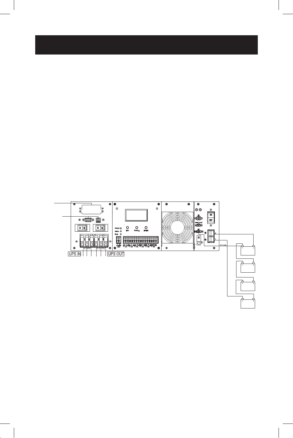
System Architecture
To Remote
Network
Connection
To User’s PC
Note: The 48V conguration is shown for SMART1548ET.
6
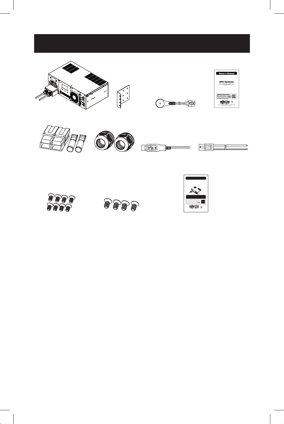
Package Contents
Note: If the listed parts on your package do not match the items you received, or if any items
appear damaged, please immediately notify your carrier agent and the supplier who prepared
your shipment.
Optional Accessories
• WEBCARDLXMINI: Network interface card for SNMP/Web control and monitoring
User Supplied Items
• Wide Temperature Range 48V DC (SMART1548ET) or 24 VDC (SMART1524ET)
Lead-Acid Battery System with included ANDERSON PA75 DC Connection kit.
• The UPS requires a user-supplied battery system that connects to the UPS via
ANDERSON PA75 DC Connection Kit.
• The batteries used must be rechargeable, deep-cycle lead-acid type.
• Select batteries that meet your high- and low-temperature requirements for
reliable operation.
• The recommended battery cable gauges are 6 AWG for the SMART1524ET
and 8 AWG for the SMART1548ET, with a maximum recommended length of
6.56 ft. / 2 m.
• The recommended DC fusing should be installed 18 in. / 0.45 m from the
battery system’s positive connection wire to the UPS.
Owner’s Manual
UPS Systems
Models: SMART1524ET and SMART1548ET
(Series Number: AG-88E6, AG-88E5)
WARRANTY REGISTRATION
Register your product today and be
automatically entered to win an ISOBAR
®
surge protector in our monthly drawing!
tripplite.com/warranty
1111 W. 35th Street, Chicago, IL 60609 USA • tripplite.com/support
Copyright © 2020 Tripp Lite. All rights reserved.
Este manual esta disponible en español en la página de Tripp Lite: tripplite.com
Ce manuel est disponible en français sur le site Web de Tripp Lite : tripplite.com
UPS System Rack-Mount
Brackets (2)
Battery
Temperature
Sensor Cable (1)
Owner’s
Manual
External Battery
Connection Kit
(1)
AC Hardwire
Strain Reliefs (2)
USB Cable (1) External Fan
Power Adapter
Cable (1)
M4 Screws (8) M6 Screws (4)
External Battery DC Connector
Cable Assembly Instruction Sheet
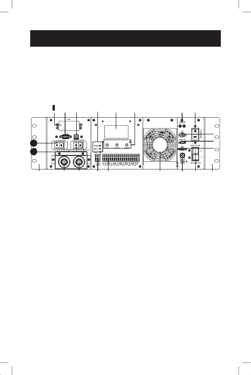
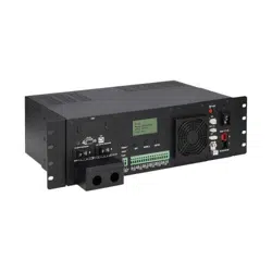
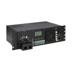
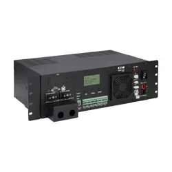
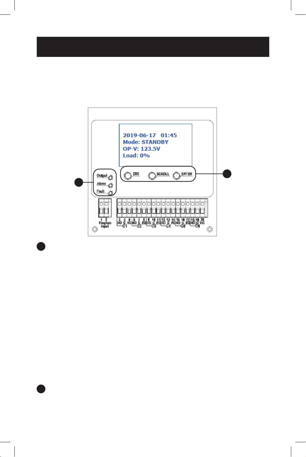
7
The UPS includes built-in USB and DB9 monitoring ports, six sets of output dry-
contacts and one set of input contacts. A slot for an optional SNMP/Web network
interface is included. The interactive front-panel LCD screen and set of three
function keys enable local monitoring of UPS and site power status, as well as
allow for setting a variety of UPS setup and control options.
UPS Front Panel
1
1
AC Input Breaker (30A)
The AC input breaker serves as both input overcurrent protection and an on/
o switch to allow AC line power into the UPS. It must be switched ON for
proper UPS operation.
2
2
AC Input Terminal Block (120V, 3 wires: L, N, G)
This terminal block is the UPS AC line power input.
• Wiring Gauge: 12 AWG recommended
• Torque Specications: 13 in•lb (1.47 N•m)
3
3
AC Output Breaker (30A)
The AC output breaker serves as both output overcurrent protection and
an on/o switch to allow UPS AC output to pass through to connected
equipment. It must be switched ON for proper UPS operation.
4
4
AC Output Terminal Block (120V, 3 Wires: L, N, G)
This terminal block is the UPS AC line power output.
• Wiring Gauge: 12 AWG recommended
• Torque Specications: 13 in•lb (1.47 N•m)
5
5
Input Contact (2 wires: Program Input 1 & 2)
To activate a programmable contact-closure input alarm to the UPS, short
pins 1 & 2. Refer to LCD MENU TREE / SETTINGS / INPUT CONTACT section for
more information.
• Wiring Gauge: Up to 12 AWG recommended
• Torque Specications: 4.5 in•lb (.51 N•m)
Features
3
1
1
1
21
2
2
J
J
J
J
K
K
L
L
M
M
N
N
O
O
P
P
Q
Q
R
R
S
S
T
T
4
4
5
5
6
6
7
7
8
8
9
9

8
Features
6
6
Dry Contacts: 6 Sets of Output Dry Contacts (C1, C2, C3, C4, C5, C6)
Each dry contact supports Normally-Open (NO) or Normally-Closed (NC)
signaling. There are three wiring contact positions per channel (NO, C, NC).
Refer to LCD MENU TREE / SETTINGS / DRY CONTACT section for more
information.
• Wiring Gauge: Up to 12 AWG recommended
• Torque Specications: 13 in•lb (1.47 N•m)
7
7
Internal Fan
The internal fan reduces operating temperature inside the UPS. The fan runs
continuously when the UPS is running by pulling cool air from the front-side of
the UPS and exhausting warmer air through the UPS rear vents. Do not block
input or output ventilation. The fan can be replaced via the front panel by a
trained electrical technician.
Note: If installing a replacement fan, make sure the fan is of equal size and rating.
8
8
Grounding Lug
This connector provides a permanent ground connection for the UPS.
• Wiring Gauge: 12 AWG recommended
• Torque Specications: 13 in•lb (1.47 N•m)
9
9
Battery Connector
The external battery connector enables the connection of a 48V DC
(SMART1548ET) or 24V DC (SMART1524ET) battery system to the UPS.
J
J
Rack-Mounting Brackets
The rack mounting brackets enable two-point mounting of the UPS into a 19-
inch equipment rack enclosure. Screws are provided to attach the mounting
brackets to the UPS power module. Rack-mount installation screws and
hardware (if needed) are user-supplied.
K
K
Battery Temperature Connector
The battery temperature sensor is included with the UPS power module.
The sensor reports temperature of the battery system to the UPS so that the
most ecient charging prole can be used to keep batteries fully charged and
increase battery lifespan. Connect the remote end of the temperature sensor
to the negative terminal of the battery. Connect the other end of the sensor
to the BTS connector on the UPS.
Installation and wiring requires a trained technician.

9
Features
L
L
External Fan Connector
This connector supplies 24V DC (SMART1524ET) or 48V DC (SMART1548ET) 3A
maximum to power a user-supplied external fan to cool a UPS installed in an
enclosure. The fan is powered ON via user-controllable temperature settings,
as reported by the UPS system’s built-in temperature sensor. An external fan
power adapter cable is included with the UPS. Fan adapter wire gauge is
22 AWG.
Installation and wiring requires a trained technician.
M
M
PTS Control Connector
Connect the PTS / Power Transfer Switch option here.
N
N
External Battery Breaker
(100A for 24V DC Systems, 60A for 48V DC Systems)
The External Battery Breaker serves as both DC input overcurrent protection
and an on/o switch to allow DC battery power into the UPS. It must be
switched on for proper UPS operation.
O
O
Battery Voltage Test Points
These test points allow you to measure battery voltage. They accept 2 mm
diameter test probe tips. The battery circuit breaker must be ON to measure
battery voltage. CAUTION: The battery test points are for voltage sensing
only and should NEVER be used as an output DC power source.
P
P
Function keys (ESC, SCROLL, ENTER)
Located directly under the LCD panel, these buttons are used to operate and
control the UPS via the LCD panel.
Q
Q
LCD Panel
The 2.5-inch LCD display enables control of UPS operation and settings.
R
R
Indicator LEDs
These LEDs with color-coded messaging report Output (green), Alarm (yellow)
and Fault (red) status. Refer to the Troubleshooting section for alarm and
fault messaging information.
S
S
USB Port
This optional USB port allows UPS management via local terminal console.
T
T
RS-232 Port
This optional RS-232 port allows UPS management via local console.
1
1
21
Network Interface Card Slot
This optional slot can be used with Tripp Lite’s WEBCARDLXMINI accessory
card and a limit of one optional “E2” environmental sensor for remote
management and monitoring via secure web browser or SNMP protocols. See
the documentation provided with the accessory card for installation and set-
up conguration information.
Attention! – When the optional slot is in use, the RS-232/USB
communications ports are disabled.
10
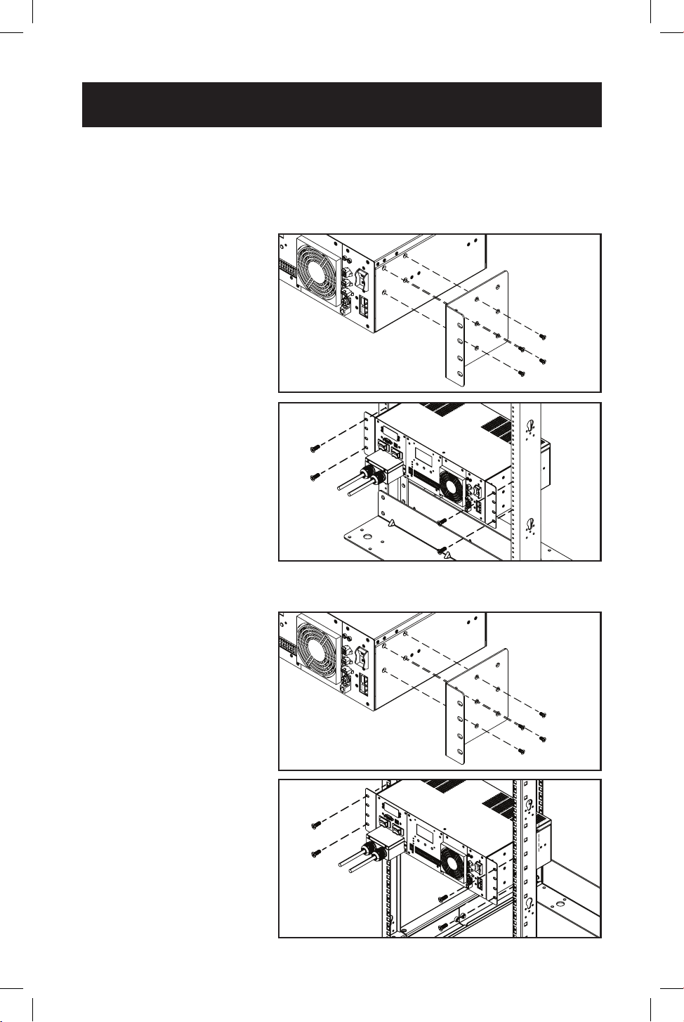
Mounting
It is recommended UPS equipment be mounted inside an enclosure to provide
protection from weather conditions.
2-Post Rack Mounting the UPS
1
1
With the included screw
set, attach the UPS
mounting brackets.
2
2
With user-supplied
screws, attach the
UPS to the forward
mounting rails of the
2-post rack. Tighten all
screws securely.
4-Post Rack Mounting the UPS
1
1
With the included screw
set, attach the UPS
mounting brackets.
2
2
Attach the UPS
mounting brackets to
the forward mounting
rails with user-supplied
screws appropriate
for the rack enclosure
used. Tighten all screws
securely.
1
1
1
1
2
2
2
2
11
Mounting
Models SMART1524ET, SMART1548ET
UPS Dimensions (H x W x D) 5.24 x 15.75 x 9.45 in. / 133 x 400 x 240 mm
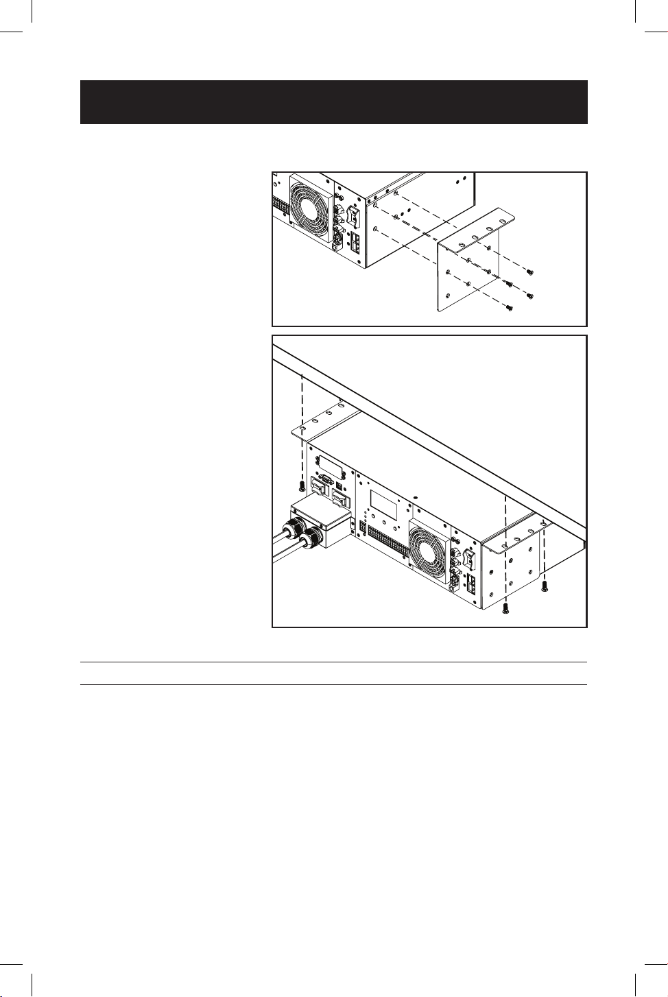
Desktop Mounting the UPS
1
1
With the included screw
set, attach the UPS
mounting brackets.
2
2
With user-supplied
screws, attach the UPS
to the desktop surface.
1
1
2
2
12
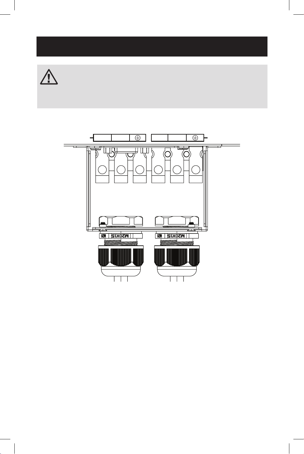
Wiring the UPS
WARNING! All electrical wiring must be performed by a qualied
electrician or trained professional. Make sure line power is
OFF. Switch OFF UPS input and output breakers before making
any electrical connections. Adhere to all electrical codes when
wiring the input connections.
AC Input and Output Wiring
AC IN
L N L N
AC OUT
AC input and output wiring requires 12 AWG gauge wiring with a torque
specication of 13 in•lb (1.47 N•m).
• Install the input and output hardwire terminal strain reliefs prior to securing AC
wiring to the UPS.
• Connect 120V AC line power input to the L, N and G “AC IN” terminals of the
UPS.
• Connect 120V AC UPS output from the L, N and G “AC OUT” terminals of the
UPS to the connected equipment.
13
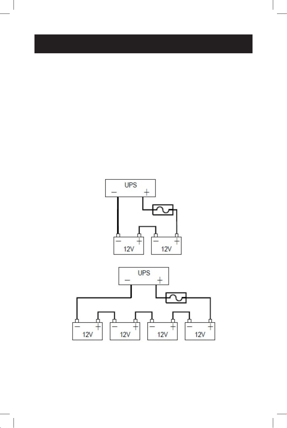
Wiring the UPS
External Battery Connections
(Deep-Cycle Lead-Acid Batteries Only)
The UPS supports a user-supplied and assembled 24V DC (for SMART1524ET)
or 48V DC (for SMART1548ET) battery system. The batteries used must be
rechargeable, deep-cycle lead-acid type. Select batteries that meet your
temperature requirements. Connect batteries into a 24V DC (SMART1524ET)
or 48V DC (SMART1548ET) UPS system, as shown below. A battery bank of at
least 100Ah, but not more than 200Ah, is recommended. For the battery set, the
recommended battery cable gauges are 6 AWG for the SMART1524ET and 8 AWG
for the SMART1548ET, with a maximum recommended length of 6.56 ft. / 2 m. The
SMART1548ET requires a 48V 70A rated fuse bank. The SMART1524ET requires a
24V 150A rated fuse bank. The battery system attaches to the UPS via the included
External Battery Connection Kit (refer to the External Battery DC Connector Cable
Assembly instruction sheet for how to wire the external battery system to the
UPS).
Battery Connection for 24V UPS System
Battery Connection for 48V UPS System

14
Wiring the UPS
Additional Wiring Connections (Optional)
• USB connector
• DB9 RS-232 connector
• Output dry contacts
• Program input contacts
• WEBCARDLXMINI monitoring card and network cabling
• External fan connector adapter cable is included with the UPS. The
recommended wire gauge for connection is 22 AWG.

15
Operation
Basic On/O and Manual UPS Test Verication
Before powering on the UPS, make sure the batteries are fully charged and input
line power is within the congured voltage limits of the UPS (factory default is 88
to 152V AC). The UPS will not turn on to provide AC output without a charged
battery set connected. To verify proper operation and familiarize yourself with UPS
operation, performing these three basic operations prior to putting the UPS into
service is recommended.
1
1
Turn on the UPS in Line Power Mode
1.1 Switch “ON” the battery circuit breaker.
The fan and all LEDs will illuminate momentarily. The LCD display will report
STARTUP, then the yellow ALARM LED will illuminate and a series of UPS
status notication screens will be available to view.
1.2 Switch “ON” the AC Input circuit breaker.
For approximately 30 seconds, the UPS will monitor AC input line power and
turn on if input is valid. The yellow ALARM LED will continue to illuminate. The
LCD may report the initial turn-on sequence as recovery from a power failure.
Press the ESC button to clear these notications and view the main UPS
status screen.
1.3 Switch “ON” the AC Output circuit breaker.
To power connected equipment, switch ON the AC output circuit breaker
to enable UPS output. You may need to press the ESC button to clear any
notications and view the main UPS status screen.
2
2
Verify Battery Backup Operation
Note: Battery mode testing can be performed immediately after installation with a small
test load. For testing at higher loads, it is recommended the battery bank be allowed to
charge for 24 to 48 hours, or until the UPS reports 100% battery charge.
2.1 Switch the UPS from AC LINE POWER MODE to BATTERY MODE.
Switch OFF the AC input circuit breaker to simulate a power failure. The UPS
will continue to provide AC output and the LCD screen will report BATTERY
MODE, OUTPUT VOLTAGE and LOAD LEVEL PERCENTAGE.
Note: You may need to press the ESC BUTTON to clear any notications resulting from the
loss of AC input before viewing status and measurement values on the main UPS status
screen.
2.2 Switch the UPS from BATTERY MODE to AC LINE POWER MODE.
Switch ON the AC input circuit breaker to return the UPS to AC line power
mode. The UPS will maintain the output load and the LCD screen will report
NORMAL MODE, OUTPUT VOLTAGE and LOAD LEVEL PERCENTAGE.
Notes:
• You may need to press the ESC BUTTON to clear any notications resulting from restoring
AC input before viewing status and measurement values on the main UPS status screen.
• If the UPS keeps switching between inverter and line mode, turn on the AVR buck and
boost settings via LCD. If the UPS continues to switch between inverter and line mode
with AVR engaged, change the UPS SENSE TYPE setting from UPS to GENERATOR.

16
Operation
3
3
Turn OFF the UPS
3.1 Switch OFF the OUTPUT circuit breaker.
Switch OFF the output circuit breaker to interrupt power to connected
equipment.
3.2 Switch OFF the BATTERY circuit breaker.
Switch OFF the battery circuit breaker to interrupt battery power connected to
the UPS.
3.3 Switch OFF the INPUT circuit breaker.
Switch OFF the input circuit breaker to interrupt AC line power connected to
the UPS.
All LEDs and the LCD screen will immediately turn OFF.
17
Operation
Operating the LCD / LED Control Panel
The Control Panel includes a four-line LCD display, three indicator LEDs, three LCD
function buttons, set of two program input contacts and six sets of dry contact
outputs.
A
LED Indicators
• Output LED (Green)
• Solid ON: AC output is on (UPS is operating in LINE POWER MODE).
• Flashing OFF and ON: AC output is on (UPS is operating in BATTERY
MODE).
• OFF: AC output is o. The output LED will be o when a local or remote
AC Output “OFF” control command is executed from the LCD, WEB or
Terminal Console session.
• Alarm LED (Yellow)
• Solid ON: UPS output is on.
There is an active alarm indicating a condition not serious enough to
keep the UPS from providing output power.
• Fault LED (Red)
• Solid ON: UPS output is o.
There is an active alarm indicating a serious condition that caused the
UPS to stop providing output.
B
LCD Function Buttons
• ESC: Moves the LCD back to the previous menu or page.
• SCROLL: Moves the LCD forward to the next selection or page.
• ENTER: Conrms selection of the scrolled value or sub-menu function.
A
B

18
Operation
LCD Menu Tree
The LCD MAIN MENU is viewable by pressing the ENTER button anytime you are
viewing the Main UPS Status Screen. There are 5 MAIN MENU options:
1. STATUS
2. EVENT LOG
3. SETTINGS
4. CONTROL
5. HELP
LCD Menu Overview
Each of the menu options can be used to receive detailed UPS status information,
enable user conguration options and perform operational testing. Use the LCD
function buttons to scroll, view, select and enter on-screen information. Below is a
detailed overview listing of the 5 MAIN MENU LCD items:
1.STATUS 2.EVENT LOG 3.SETTINGS 4.CONTROL 5. HELP
SERIAL NO. ACTIVE LOG DRY CONTACT SELF TEST
UPS MODEL
NUMBER
I/P-V (Input volts) HISTORY LOG INPUT CONTACT DRY TEST
I/P-F (Input Hz) AVR FEATURE EXT FAN TEST
BAT V (Battery volts) LINE QUALIFY ON/OFF CTRL
BAT T (Battery temp) LINE DETECT
EVENT/TM RESET
O/P-V (Output volts) SENSE TYPE
O/P-F (Output Hz)
BAT TEMP COMP
O/P-P (Output VA) EXT. FAN
O/P-P (Output W) BAT LOW VOLT
LOAD (Load %) CHARGER
RunTM (Runtime remaining)
BATT CAP
InvEV (Battery events) BATT COEF
InvTM (Battery time) BATT GROUP
BukEV (Buck events) BACKUP TIMER
BukTM (Buck time) DEFAULT UPS
BstEV (Boost events) DEFAULT SNMP
BstTM (Boost time) BACKLIGHT
C1 (C1 status) TEST TIME
C2 (C2 status) SET DATE TIME
C3 (C3 status) PASSWORD
C4 (C4 status)
C5 (C5 status)
C6 (C6 status)
MainFW (Firmware)
LCDFW (Firmware)
HW (Version)

19
LCD Menu Explanations
1. STATUS: There are six UPS STATUS information screens that report detailed
information on UPS operating factors and current site power conditions.
First STATUS Screen (3 selections)
• S/N (UPS serial number)
• I/P-V (UPS input line voltage)
• I/P-F (UPS input line frequency, Hz)
Second STATUS Screen (4 selections)
• BAT V (UPS battery voltage)
• BAT T (UPS battery sensor temperature)
• O/P-V (UPS output voltage)
• O/P-F (UPS output frequency, Hz)
Third STATUS Screen (4 selections)
• O/P-P...VA (UPS output load in VA)
• O/P-P...W (UPS output load in watts)
• LOAD (UPS output load percentage)
• RunTM (Runtime remaining)
Fourth STATUS Screen (4 selections)
• InvEV (Number of battery events since last reset)
• InvTM (Total hours on battery mode since last reset)
• BukEV (Number of times in BUCK mode since last reset)
• BukTM (Total hours in BUCK mode since last reset)
Fifth STATUS Screen (6 selections)
• BstEV (Number of times in BOOST mode since last reset)
• BstTM (Total hours in BOOST mode since last reset)
• C1 (O-On status of C1 output contact)
• C2 (O-On status of C2 output contact)
• C3 (O-On status of C3 output contact)
• C4 (O-On status of C4 output contact)
Sixth STATUS Screen (5 selections)
• C5 (O-On status of C5 output contact)
• C6 (O-On status of C6 output contact)
• MainFW (UPS rmware version)
• LCDFW (UPS LCD rmware version)
• HW (UPS hardware version)
Operation

20
Operation
2. EVENT LOG: There are two UPS EVENT LOG information pages to report active
and logged events.
First EVENT LOG Screen (1 selection)
• ACTIVE LOG (Displays all active UPS notications)
Second EVENT LOG Screen (1 selection)
• HISTORY LOG (View or clear logged notications)
- Select INQUIRY to display past notications (200 events maximum)
- Select CLEAR to delete all past notications
3. SETTINGS: There are four UPS SETTINGS pages that enable user conguration
options. Each of these pages contain multiple sub-menu options.
Note: PASSWORD REQUIRED. (Factory default password is 1111)
Enter the default password by using the scroll button to select the numerical
value. Press the Enter button after every value. The LCD message will conrm
that it has accepted the password.
If the wrong password is used, the LCD screen will report “ACCESS DENIED!”
Re-enter the correct password.
• Upon successful UPS setting change, the screen will report “SETTING OK!”
• If the setting is not accepted by the UPS, the screen will report “SETTING
FAILED!”
First SETTINGS Screen (4 selections)
• DRY CONTACT: Enables conguration of UPS output dry contacts. Navigate
via LCD panel to dry contacts C1/C2/C3/C4/C5/C6. Congure each contact to
match the desired notication type. Disable any unused contacts. Selection
options for each contact include:
ON BATTERY (Energizes when UPS is in battery mode)
BATTERY LOW (Energizes in battery mode when batteries are low)
TIMER TIME UP (Energizes in battery mode after the congured time threshold)
SUMMARY ALARM (Energizes when any UPS alarm occurs)
UPS FAULT (Energizes when any UPS fault occurs)
UPS SHUTDOWN (Energizes when UPS output is o)
DISABLE (Dry contact is not energized)
• INPUT CONTACT: Enables conguration of one user-supplied UPS input
CONTACT-CLOSURE sensor. Navigate via LCD panel to select the closest naming
option for the reported condition from the sub-menu list. Once congured,
shorting the input sensor contacts will report the external condition by the
selected name. Contact closure sensor naming options include:
USER PROGRAM (Use this naming option for other sensor types)
EXT. ALARM (External alarm)
EXT. BAT ALARM (External battery alarm)
EXT. FAN FAILED (External fan failure)
DOOR UNLOCK (Door unlock)
Note: Select "User program" if your sensor type is not listed.

21
Operation
• AVR FEATURE: Enables conguration of AVR / AUTO-VOLTAGE REGULATION
to correct undervoltage and overvoltage conditions. Undervoltage Correction
(BOOST) and Overvoltage Correction (BUCK) functions can be enabled and
disabled independently of each other. To congure, navigate via LCD panel
to the BUCK and BOOST screens and select ENABLE/DISABLE for each from
the sub-menu list. Selection options include:
BOOST (Select to ENABLE/DISABLE brownout boost protection)
BUCK (Select to ENABLE/DISABLE overvoltage buck protection)
• LINE QUALIFY: Enables conguration of the amount of time the UPS
monitors line power quality for stability before switching to LINE POWER
MODE as AC power is restored. To congure, navigate via LCD panel to the
LINE QUALIFY screen and select the desired time duration from the sub-
menu list (default value = 30 SEC.). Selection options include:
3 SEC. (UPS returns to line-power mode after 3 seconds of valid AC input)
10 SEC. (UPS returns to line-power mode after 10 seconds of valid AC input)
30 SEC. (UPS returns to line-power mode after 30 seconds of valid AC input)
Second SETTINGS Screen (4 selections)
• LINE DETECTION: Enables conguration of the switchover voltages between
AC and BATTERY modes, plus AVR activation voltages for AVR BOOST and
AVR CUT operation. To congure, navigate via LCD to the LINE DETECT
screen and select the desired transfer voltage points for each of the six
conditions. Selection options include:
LINE HIGH (Sets the high UPS transfer voltage from line-power mode to
battery mode)
Note: Specify LINE HIGH switchover voltage via LCD (default = 152V AC).
LINE LOW (Sets the low UPS transfer voltage from line-power mode to
battery mode)
Note: Specify LINE LOW switchover voltage via LCD (default = 88V AC).
HIGH GAP (Sets the threshold voltage used to calculate the transition from
battery-power mode back to line-power mode. Default = 5V AC.)
LOW GAP (Sets the threshold voltage used to calculate the transition from
battery-power mode back to line-power mode. Default = 5V AC.)
BOOST VOLT (Sets the low UPS boost-mode activation voltage for
undervoltage correction)
Notes:
• Specify BOOST VOLT activation setting for AVR boost mode operation
(default = 102V AC).
• Boost mode automatically deactivates as the input voltage recovers to the BOOST VOLT
+ LOW GAP value. (Default = 102V AC + 5V AC = 107V AC.)

22
Operation
BUCK VOLT (Sets the high UPS buck-mode activation voltage for overvoltage
correction)
Notes:
• Specify BUCK VOLT activation setting for AVR buck-mode operation
(default = 128V AC).
• Buck mode automatically deactivates as the input voltage recovers to the BUCK VOLT -
HIGH GAP value. (Default = 128V AC - 5V AC = 123V AC.)
• SENSE TYPE: Enables conguration of UPS AC power sensing to maximize
UPS operation for standard line power AC and generator power applications.
To congure, navigate via LCD panel to the SENSE TYPE screen and select
the desired input power conguration to the UPS or GENERATOR (default)
setting. Selection options include:
UPS (UPS is congured for standard AC line power)
GENERATOR (UPS is congured for generator power applications)
• BAT TEMP COMP: Enables conguration of UPS BATTERY TEMPERATURE
COMPENSATION-related oat voltage reduction during high temperature
conditions in mV/°C/Cell units. To congure, navigate via LCD panel to the
BAT TEMP COMP screen and select the desired temperature compensation
value. Selection options include:
REDUCE BY -2.5mV
REDUCE BY -3.0mV (default value)
REDUCE BY -3.5mV
REDUCE BY -4.0mV
• EXT. FAN: Enables conguration of EXTERNAL FAN activation temperature.
To congure, navigate via LCD to the EXT. FAN screen and select the desired
temperature for the external fan to turn on (default = 25C).
Third SETTINGS Screen (4 selections)
• BAT LOW VOLT: Enables conguration of BATTERY LOW VOLTAGE for
notication that batteries are nearly depleted as the UPS is running in
battery mode. To congure, navigate via LCD to the BAT LOW VOLT screen
and select the desired low-battery voltage setting.
SMART1548ET
selection options are 42.0 to 55.0V DC (default value is 46V DC)
SMART1524ET selection options are 21 TO 27.5V DC (default value is 23V DC)
• CHARGER: Enables conguration of CHARGER CURRENT. To congure,
navigate via LCD to the CHARGER I screen and select the desired maximum
charging current. Selection options are: 2 AMP, 4 AMP, 6 AMP, 8 AMP and 10
AMP (default = 2AMP).

23
Operation
• BATTERY CAPACITY: Enables conguration of external battery pack
capacity. To congure, navigate via LCD to the BAT CAP setting screen and
select the desired capacity.
7Ah
9Ah (default value)
10Ah
12Ah
17Ah
26Ah
40Ah
65Ah
100Ah
• BATTERY COEFFICIENT: Enables adjustment of battery coecient as
battery system ages to provide a better estimation of runtime remaining.
To congure, navigate to the Bat Coef screen and enter a coecient setting
from 0.5-2.0 (default value = 1.0).
Fourth SETTINGS Screen (4 selections)
• BAT GROUP: Enables adjustment to the size of external battery system
capacity by groups. If you are using a 200Ah battery system (2x 100Ah
batteries), you would set battery group to 2. To congure, navigate to the Bat
Group screen and enter the desired conguration. Settings range from 01-
10 (01 is default value).
• BACKUP TIMER: Enables conguration of the BACKUP TIMER. This is the
amount of runtime the UPS supports in battery mode before sending a
congured dry contact notication. To congure, navigate to the BACKUP
TIMER screen and select the desired duration. Selection options are between
0 and 480 minutes, in increments of 15 minutes (default = 120 min.).
• DEFAULT UPS: Returns the UPS back to the factory default conguration. To
congure, navigate to the DEFAULT UPS screen and select the YES option.
• DEFAULT SNMP: Reserved for future use.
Fifth SETTINGS Screen (4 selections)
• BACKLIGHT TIMER: Selecting this option enables adjustment the amount
of time the LCD BACKLIGHT will stay on. To congure, navigate to the
BACKLIGHT screen and select the desired setting. Selection options are: 5
MIN. and ALWAYS (default = 5 MIN).
• TEST TIMER: Enables the conguration of the UPS TEST TIME, the maximum
duration that the UPS will perform a battery mode self-test. To congure,
navigate to the TEST TIME screen and enter the desired maximum test time
duration from 1 to 255 minutes (factory default is 1 minute).
• SET DATE TIME: Enables the conguration of the UPS YEAR, DATE and TIME.
To congure, navigate to the SET DATE TIME screen and enter the year, date
and current time.

24
Operation
• PASSWORD: Enables the selection of a new, user-selected 4-digit password.
To congure the UPS with a new password, navigate to the PASSWORD
screen and select the SELECTING PASSWORD on-screen option. The UPS
will request a new 4-digit password be entered. Once entered, the UPS will
display SETTING AGAIN and request the same 4-digit password be entered
again for conrmation.
Note: Factory default password is 1111; please keep track of the new password to enable
future settings and control changes.
4. CONTROL: There are two pages of UPS CONTROL settings that are available
to perform testing, display output power status and reset UPS events. Each of
these pages contain sub-menu UPS control options.
Note: PASSWORD REQUIRED. (Factory default password is 1111)
First CONTROL Screen (4 items)
• SELF TEST: Selecting the SELF TEST option will cause the UPS to switch to
battery mode for the duration selected in the SETTINGS/TEST TIME eld
(factory default is one minute). The UPS must be in Normal, Boost or Buck
mode before a self-test will successfully initiate. To initiate a SELF TEST,
navigate to the SELF TEST screen and select the START option. Once entered,
the UPS will switch to battery mode to test the battery, inverter and battery
transfer circuits for proper operation. To interrupt a self-test, select the STOP
option from the SELF-TEST screen.
• DRY TEST: Selecting the DRY CONTACT TEST option will simultaneously
test all output dry contacts for 1 minute. To initiate a DRY CONTACT TEST,
navigate to the DRY TEST screen and select ON or OFF for the desired testing
conguration. Selection options include:
Select ON to energize all 6 dry contacts for 1 minute
Select OFF to de-energize all 6 dry contacts for 1 minute
Select CANCEL to cancel the test immediately
• EXT FAN TEST: Selecting the EXTERNAL FAN TEST option will test the
external fan for a period of 1 minute. To initiate an EXTERNAL FAN TEST,
navigate to the EXT FAN TEST screen and select ON or OFF for the desired
testing conguration. Selection options include:
Select ON to energize the external fan for a period of 1 minute
Select OFF to de-energize the external fan for a period of 1 minute
Select CANCEL to cancel the test immediately
• ON/OFF CONTROL: Selecting the UPS OUTPUT option enables the setting
of UPS output power to be OFF or ON in Inverter, Boost, Buck and Normal
modes. To turn UPS OUTPUT OFF or ON in these operating modes, navigate
to the UPS OUTPUT screen and select the ON or OFF setting.
Select ON to enable UPS output in Inverter, Boost, Buck and Normal modes
Select OFF to disable UPS output in Inverter, Boost, Buck and Normal modes

25
Operation
Second CONTROL Screen (1 item)
• EVENT/TM RESET: Selecting the EVENT/TM RESET option resets all EVENTS
and TIME DURATIONS stored in the UPS. To reset all events and times,
navigate to the RESET EVENT/TM screen and select YES or NO from the sub-
menu options.
Select YES to reset all Events and Time Durations
Select NO to keep all stored Events and Time Durations
5. HELP: The HELP menu item displays UPS MODEL NUMBER information. To
display the UPS model number, navigate to the HELP screen and press the
Enter button. Then press the Esc button to return to previous menu.
6. COMMUNICATIONS
Your UPS can be congured, managed and monitored via one of the available
communication ports listed below. Choose the connection type most suitable
for your application environment.
• ACCESSORY CARD SLOT: This optional slot can be used with Tripp
Lite’s WEBCARDLXMINI accessory card and a limit of one optional “E2”
environmental sensor for remote management and monitoring via secure
web browser or SNMP protocols. See the documentation provided with the
accessory card for installation and set-up conguration information.
Attention! When the optional slot is in use, the RS-232/USB
communications ports are disabled.
• RS-232 / USB CONSOLE: The front-panel RS-232 and USB monitoring ports
enable local monitoring of UPS status, viewing event logs, setting parameters
and controlling the UPS using a terminal emulation program, such as
Windows HyperTerminal. To use this feature, connect a computer to either
the RS-232 or USB port and open your terminal emulation program. Setup
and operation using Windows HyperTerminal is included here and will vary
by the VT-100 terminal emulation program used.
26
Operation
RS-232 / USB Communications Interface
UPS settings, control and status functions can be accessed using Windows
HyperTerminal. The RS-232 / USB menus are hierarchical. Press ENTER to access
the main menu. Type in the sub-menu number and press ENTER to access a
particular sub-menu. Press the ESC key to return to the prior menu. Press ENTER
to refresh the screen or the Status, Faults and Alarms readouts. The main menu
displays the sub-menu line numbers, line status, output status and any faults or
alarms that may be present.
The MAIN MENU screen with complete status information is shown below the
console setup instructions.
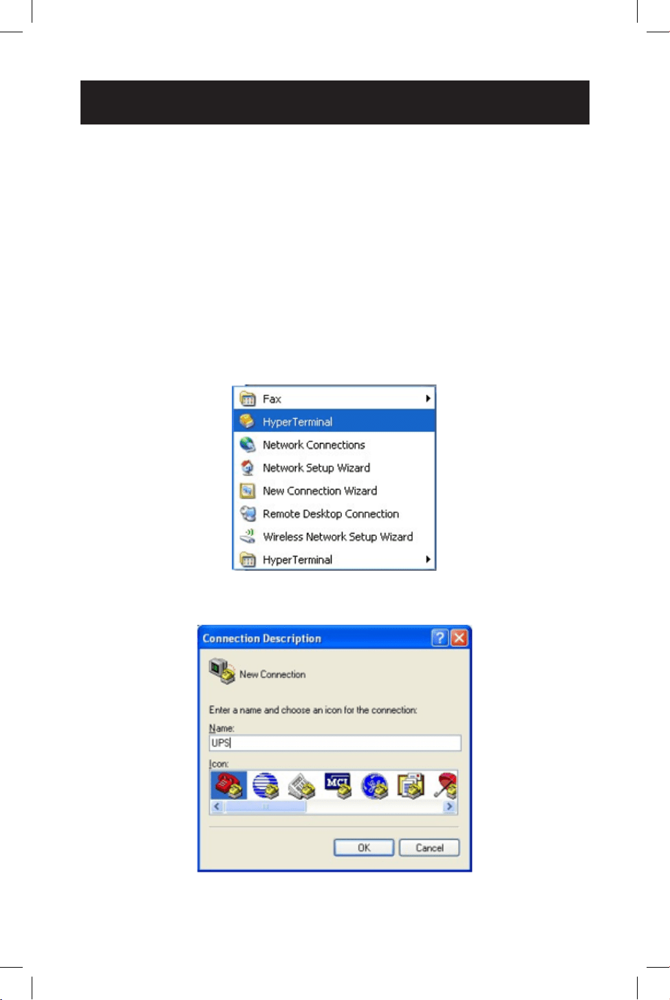
HyperTerminal Set Up
1
1
Open the Windows HyperTerminal program.
2
2
The CONNECTION DESCRIPTION screen will display. Enter a name and select
an icon for your UPS, then click OK.
27
Operation
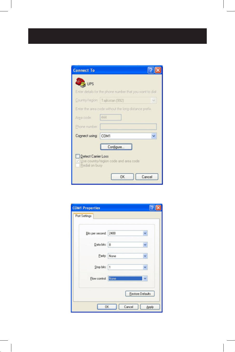
3
3
The CONNECT TO screen will display. Select the COM port from the drop-
down menu, then click OK.
4
4
The COM PROPERTIES screen will display. Select the port setting as shown,
then click OK.
28
Operation
5
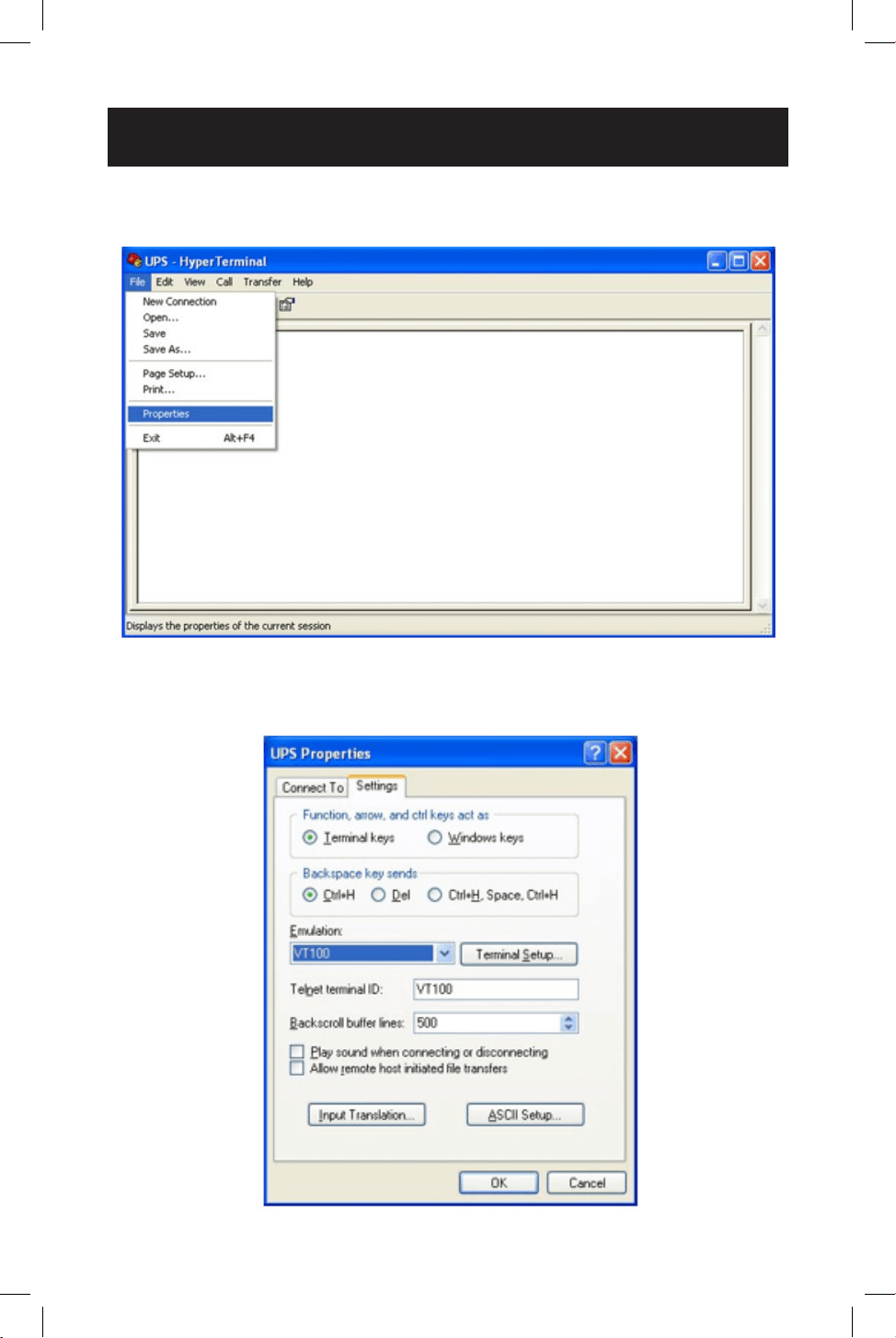
5
A blank window with the entered device name will display. Select PROPERTIES
from the FILE MENU and click on it.
6
6
The PROPERTIES screen will display. Click to open the SETTINGS tab and select
options as displayed here, then click to open the on-screen ASCII SETUP
option.
29
Operation
7
7
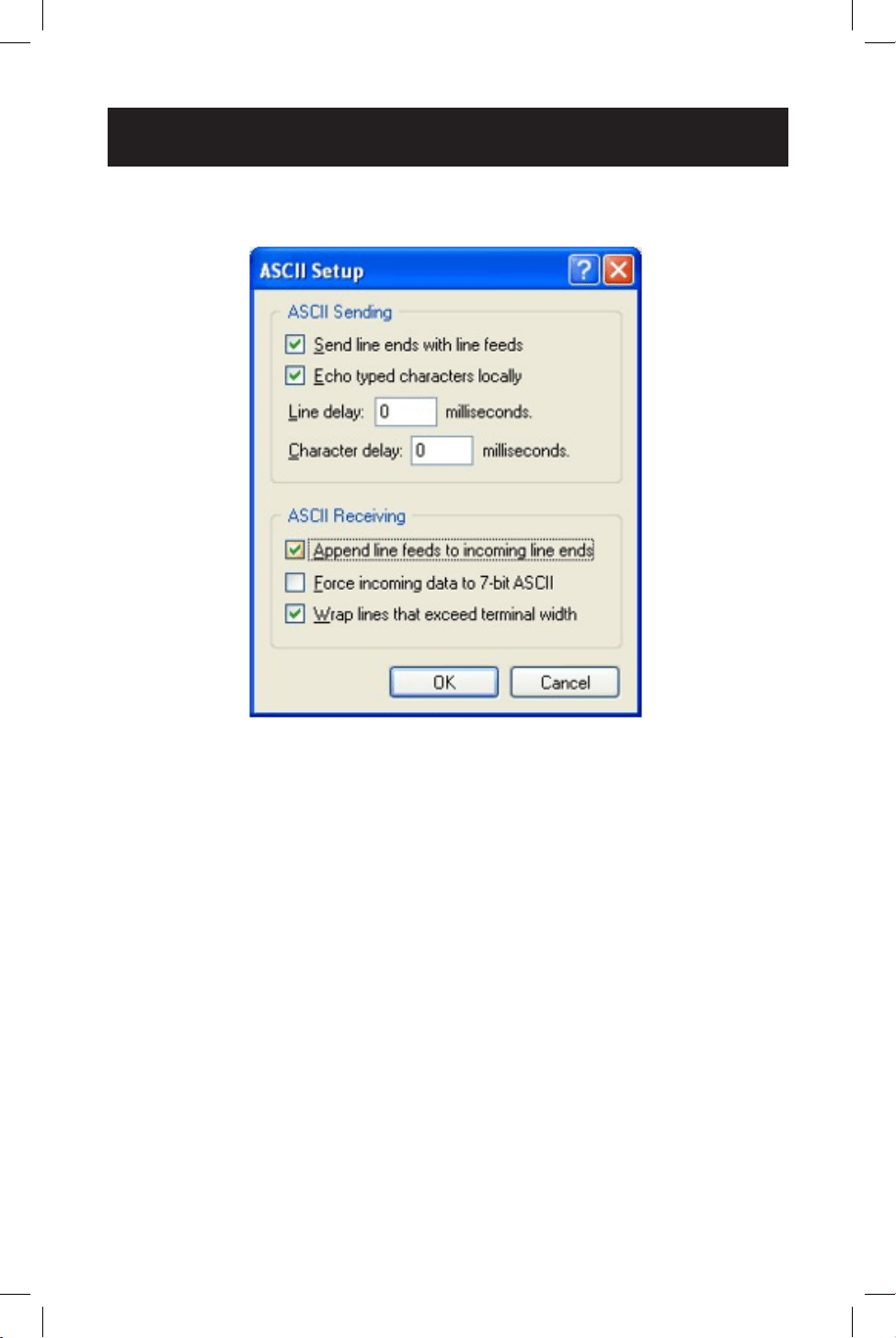
The ASCII SETUP window will open. Select the options as shown here, then
press OK to complete your HyperTerminal setup.

30
Operation
RS-232 / USB Main Menu
UPS settings, control and status functions can be accessed using Windows
HyperTerminal. The RS-232 / USB menus are hierarchical. Press ENTER to access
main menu. Type in the sub-menu number and press ENTER to access a particular
sub-menu. Press ENTER to refresh the screen, the Status, Faults, and Alarms
readouts. The main menu displays the sub-menu line numbers, line status,
output status and any faults or alarms that may be present. The MAIN MENU with
complete status information is shown here:
UPS Model: SMART1548ET / SMART1524ET
ID: ####
[0-MAIN MENU]
1 Unit Specification
2 Input / Output Values
3 Control
4 System Setting
5 Line Conditioning Setup
6 Programmable Contacts Setup
7 Event Log View
8 Login Administrator
Date & Time : YEAR/MONTH/DAY, HOUR/MIN./SEC.
Sense Type : [UPS/Generator]
Line Status : [Normal]
Output Status : [Normal]
Contact Status :
Contact C1 ==> [DISABLED]/NOT ACTIVATED]
Contact C2 ==> [DISABLED]/NOT ACTIVATED]
Contact C3 ==> [DISABLED]/NOT ACTIVATED]
Contact C4 ==> [DISABLED]/NOT ACTIVATED]
Contact C5 ==> [DISABLED]/NOT ACTIVATED]
Contact C6 ==> [DISABLED]/NOT ACTIVATED]
Ext.Fan Status : [Activated/Not Activated]
Faults : [None]*
Alarms : [None]*
*Default values shown. The full set of available display values for SENSE TYPE, LINE
STATUS, OUTPUT STATUS, FAULTS and ALARMS elds are listed here.
• SENSE TYPE: UPS, Generator
• LINE STATUS: Normal, Not Good
• OUTPUT STATUS: Self Test, Inverter, Buck, Boost, Normal, O
• FAULTS: Bus Voltage Over, Bus Voltage Under, Bus Soft Fail, Output Short, INV
Output Voltage Low, INV Output Voltage High, Over Temperature, Fan Fault,
Battery Voltage High, Overload

31
Operation
• ALARMS: Bus Voltage Over, Bus Voltage Under, Bus Soft Fail, Line Fail, Output
Short, INV Output Voltage Low, INV Output Voltage High, Over Temperature, Fan
Fault, Battery Voltage High, Battery Voltage Low, Overcharge, Battery Voltage
Under, Temp Derating, Overload, Eeprom Fault, Battery Temperature Low,
Battery Temperature High, BTS Disconnect, Battery Disconnect
RS-232/USB Menu Tree
Note: It is recommended to enter passwords in 8 LOGIN ADMINISTRATOR rst for access to sub-
menu 3~7. The factory default password is 1111.
The UPS menu tree is shown below:
UPS Model: SMART1548ET / SMART1524ET
ID: ####
[0-MAIN MENU]
1 Unit Specification
2 Input / Output Values
3 Control
4 System Setting
5 Line Conditioning Setup
6 Programmable Contacts Setup
7 Event Log View
8 Login Administrator
Menu Overview
These menu options can be used to receive detailed UPS status information,
enable user conguration options and perform operational testing. Use your
terminal emulation software to view, select and enter on-screen information. A
detailed overview listing each of the 8 MAIN MENU LCD item is listed below:
1. Unit Specications - This screen reports basic specications for the UPS.
[0-MAIN MENU]
[1-Unit Specifications]
Unit Model SMART1548ET / SMART1524ET
Unit Frequency 60 Hertz
Output Voltage 120 Volts
Output VA 1500VA
Battery Voltage ## Volts
Max Chgr Current ##.#A
Panel Firmware Ver ##.##
Main Firmware Ver ##.##
Hardware Ver ##.##

32
2. Input / Output Values - This screen reports UPS input and output values.
[0-MAIN MENU]
[2-INPUT/OUTPUT VALUES]
Input:-
Voltage ###.# Vac
Frequency ##.# Hz
Output:-
Voltage ###.# Vac
Frequency ##.# Hz
Power #### Watt
VA #### VA
Load Percent ### %
Battery:-
Temperature ## Deg C
Voltage ##.## Vdc
Event-Timer
INVERTER EVENTS #####
INVERTER TIMER ####.# Hours
Boost EVENTS #####
Boost TIMER ####.# Hours
Buck EVENTS #####
Buck TIMER ####.# Hours
3. UPS Control Actions - This screen oers control of UPS operation.
[0-MAIN MENU]
[3-Control]
30) Self Test
31) Dry Contact Test
32) External Fan Test
33) Ups Output
34) Event/Timer Reset
UPS Control Sub-Menu Options
Self Test (#30) - Selecting the SELF TEST option will cause the UPS to switch
to battery mode for the duration selected in the SETTINGS/TEST TIME eld
(factory default is one minute). The UPS must be in Normal, Boost or Buck
mode before a self-test will successfully be initiated. To initiate a SELF TEST,
navigate to the SELF TEST screen and select the START option. Once entered,
the UPS will switch to battery mode to test the battery, inverter and battery
transfer circuits for proper operation.
Self Test
0) Stop
1) Start
>
Operation

33
Operation
Dry Contact Test (#31) - Selecting the DRY CONTACT TEST option will
simultaneously test all output dry contacts for 1 minute. To initiate a DRY
CONTACT TEST, navigate to the DRY TEST screen and select ON or OFF for the
desired testing conguration.
Dry Contact Test
0) Off
1) On
2) Cancel
>
External Fan Test (#32) - Selecting the EXTERNAL FAN TEST option will test
the external fan for a period of 1 minute. To initiate an EXTERNAL FAN TEST,
navigate to the EXT FAN TEST screen and select ON or OFF for the desired
testing conguration.
External Fan Test
0) Off
1) On
2) Cancel
>
UPS Output (#33) - Selecting the UPS OUTPUT option enables the setting
of UPS output power to be OFF or ON in Inverter, Boost, Buck and Normal
Modes. To turn UPS OUTPUT OFF or ON in these operating modes, navigate to
the UPS OUTPUT screen and select the ON or OFF setting.
Select ON to enable UPS output in Inverter, Boost, Buck and Normal modes.
Select OFF to disable UPS output in Inverter, Boost, Buck and Normal modes.
UPS Output
0) Off
1) On
>
Reset Event (#34) - Selecting the RESET EVENT/TM option resets all EVENTS
and TIME DURATIONS stored in the UPS. To reset all events and times, navigate
to the RESET EVENT/TM screen and select YES or NO from the sub-menu
options.
Reset Event/TM
0) No
1) Yes
>

34
Operation
4. UPS System Setting - This screen oers control of UPS operating settings.
[0-MAIN MENU]
[4-SYSTEM SETTING]
40) Ext Fan On By Temperature
41) Battery Low Voltage
42) Charging Current
43) Bat cap
44) Bat coef
45) Bat group
46) Battery Temperature Compensation
47) Test Timer
48) Backup Timer
49) LCD BackLight Timer
50) Set To Default UPS
51) Set Date
52) Set Time
53) Change Password
54) Reset Password
System Setting Control Sub-Menu Options
External Fan On By Temperature (#40) - Selecting the EXTERNAL FAN
ON BY TEMPERATURE option enables conguration of the EXTERNAL FAN
activation temperature. To congure, navigate to the EXT. FAN screen and
select the desired temperature for the external fan to turn on (default = 25C).
[0-MAIN MENU]
[4-SYSTEM SETTING]
[40-EXT FAN ON BY TEMPERATURE]
Current setting is [## Deg C]
Enter new value. (20->50)
>
Battery Low Voltage (#41) - Selecting the BATTERY LOW VOLTAGE option
enables conguration of the low-voltage notication that batteries are nearly
depleted as the UPS is running in battery mode. To congure, navigate via
LCD to the BATTERY LOW VOLTAGE screen and select the desired low-battery
voltage setting (SMART1548ET default is 46VDC / SMART1524ET default value is
20V DC).
[0-MAIN MENU]
[4-SYSTEM SETTING]
[41-BATTERY LOW VOLTAGE]
Current setting is [##.# Volts]
Enter new value. [42.0->55.0]
>

35
Operation
Charging Current (#42) - Selecting this option enables conguration of
CHARGER CURRENT. To congure, navigate to the CHARGER screen and select
the desired maximum charging current. Selection options are: 2 AMP, 4 AMP, 6
AMP, 8 AMP and 10 AMP (default = 2A).
[0-MAIN MENU]
[4-SYSTEM SETTING]
[42-Charging Current]
Current setting is [## amps]
0) Set to 2 amps
1) Set to 4 amps
2) Set to 6 amps
3) Set to 8 amps
4) Set to 10 amps
>
Battery Capacity (#43) - Selecting this option enables conguration of UPS
BATTERY Capacity to match the AH of the individual batteries used in the user-
supplied external battery bank. To congure, navigate to the BAT CAP screen and
select the desired AH rating value to match the ratings of the individual batteries
used.
[0-MAIN MENU]
[4-SYSTEM SETTING]
[43-BATCAP]
Current setting is [009 AH]
0) Set to 7 AH
1) Set to 9 AH
2) Set to 10 AH
3) Set to 12 AH
4) Set to 17 AH
5) Set to 26 AH
6) Set to 40 AH
7) Set to 65 AH
8) Set to 100 AH
>
Battery Coecient (#44) - Selecting this option enables adjustment of
battery coecient as battery system ages to provide a better estimation of
runtime remaining. To congure, navigate to the Battery Coef screen and select
a coecient value from 0.5->2.0 (default value = 1.0).
[0-MAIN MENU]
[4-SYSTEM SETTING]
[44-Battery Coef]
Current setting is [1.0]
Enter new value. (0.5->2.0)
>

36
Battery Group (#45) - Selecting this option enables adjustment to the
size of external battery banks’ capacity by groups. If you are using a 200Ah
battery system (2x 100Ah batteries), you would set the battery group to 2.
To congure, navigate to the Battery group screen and select the desired
conguration. Settings range from 01->10 (default value = 01).
[0-MAIN MENU]
[4-SYSTEM SETTING]
[45-Battery group]
Current setting is [01 ]
Enter new value (01->10)
>
Battery Temperature Compensation (#46) - Selecting this option enables
conguration of UPS BATTERY TEMPERATURE COMPENSATION related oat
voltage reduction during high-temperature conditions in mV/°C/Cell units.
To congure, navigate to the BAT TEMP COMP screen and select the desired
temperature compensation value.
[0-MAIN MENU]
[4-SYSTEM SETTING]
[46-Battery Temperature Compensation]
Current setting is [-03mv/Deg C/Cell]
0) Set to -2.5mv/Deg C/Cell
1) Set to -3.0mv/Deg C/Cell
2) Set to -3.5mv/Deg C/Cell
3) Set to -4.0mv/Deg C/Cell
>
Test Timer (#47) - Selecting this option enables the conguration of the UPS
TEST TIME, the maximum duration that the UPS will perform a battery mode
self-test. To congure, navigate to the TEST TIME screen and enter the desired
maximum test time duration from 1 to 255 minutes (factory default
is 1 minute).
[0-MAIN MENU]
[4-SYSTEM SETTING]
[47-Test Timer]
Current setting is [001min)
Enter New Value
>
Operation

37
Operation
Backup Timer (#48) - Selecting this option enables conguration of the
BACKUP TIMER. This is the amount of runtime the UPS supports in battery
mode before sending a congured dry contact notication. To congure,
navigate to the BACKUP TIMER screen and select the desired duration
multiplier. Selection options between 1 and 32 increments. One increment is
equal to 0.25 hours for a maximum of 8 hours (default = [08]* 0.25 hours =
2.0 hours).
[0-MAIN MENU]
[4-SYSTEM SETTING]
[48-Backup Timer]
Current setting is [08] (Unit=0.25Hour)
Enter new value
>
LCD Backlight Timer (#49) - Selecting this option enables adjustment of the
LCD BACKLIGHT. To congure, navigate to the LCD BACKLIGHT screen and
select the desired setting. Selection options are: 5 MIN. and ALWAYS (default =
5 MIN).
[0-MAIN MENU]
[4-SYSTEM SETTING]
[49-LCD BackLight Timer]
0) 5 min
1) Always
>
Set to Default UPS (#50) - Selecting this option enables factory default
conguration of the UPS. To congure, navigate to the DEFAULT UPS screen
and select the YES option.
[0-MAIN MENU]
[4-SYSTEM SETTING]
[50-Set to Default UPS]
0) No
1) Yes
>
Set Date (#51) - Selecting this option enables the setting of the UPS date. To
congure, navigate to the SET DATE screen and enter the new YEAR / MONTH /
DAY information.
[0-MAIN MENU]
[4-SYSTEM SETTING]
[51-Set Date]
Current Date is [YEAR-MONTH-DAY]
Enter new value [##-##-##]
>

38
Operation
Set Time (#52) - Selecting this option enables setting of the UPS time. To
congure, navigate to the SET TIME screen and enter the new time. Time
displays in 24-hour format (18:00 = 6PM).
[0-MAIN MENU]
[4-SYSTEM SETTING]
[52-Set Time]
Current Time is [HOUR:MINUTE:SECOND]
Enter new value [##:##:##]
>
Change Password (#53) - Selecting this option enables the selection of a new,
user-selected 4-digit password. To congure the UPS with a new password,
navigate to the PASSWORD screen. The UPS will request a new 4-digit
password be entered. Once entered, the UPS will display SETTING AGAIN and
request the same 4-digit password be entered again for conrmation. The
factory default password is 1111. Make sure to keep track of the new password
to enable future settings and control changes.
[0-MAIN MENU]
[4-SYSTEM SETTING]
[53-Change Password]
Please Enter New Password:0000-9999
>
Reset Password (#54) – Select this option to reset the UPS back to the factory
default administrator password of 1111.
[0-MAIN MENU]
[4-SYSTEM SETTING]
[54-Reset Password]
0) No
1) Yes
>

39
Operation
5. Line Conditioning Setup - This option allows customization of the UPS
system’s line-interactive voltage regulation capabilities. CAUTION: Improperly
parameter value setting can cause permanent damage to the unit.
Changes should only be made by qualied and trained personnel.
[0-MAIN MENU]
[5-LINE CONDITIONING SETUP]
55) Buck Function
56) Boost Function
57) Sense Type
58) Line Qualify Time
59) High Limit [152] Vac
60) Low Limit [088] Vac
61) Boost Low [102] Vac
62) Buck High [128] Vac
63) High Gap [005] Vac
64) Low Gap [005] Vac
*) High back [147] Vac
*) Low back [093] Vac
*) Boost back [107] Vac
*) Buck back [123] Vac
>
Line Conditioning Sub-Menu Options
Buck Function (#55) - Selecting this option allows users to enable or disable
line interactive UPS overvoltage (BUCK) correction. Select ENABLE to turn
on overvoltage regulation. Select DISABLE to turn o overvoltage regulation
(default = Enabled).
[0-MAIN MENU]
[5-LINE CONDITIONING SETUP]
[55-Buck Function]
Current setting is [Enable]
0) Disable
1) Enable
>
Boost Function (#56) - Selecting this option allows users to enable or disable
line interactive UPS undervoltage (BOOST) correction. Select ENABLE to turn
on undervoltage regulation. Select DISABLE to turn o undervoltage regulation
(default = Enabled).
[0-MAIN MENU]
[5-LINE CONDITIONING SETUP]
[56-Boost Function]
Current setting is [Enable]
0) Disable
1) Enable
>

40
Operation
Sense Type (#57) - Selecting this option enables conguration of UPS AC
power sensing to maximize UPS operation for standard line power AC and
generator power applications. To congure, navigate to the SENSE TYPE screen
and select the desired input power conguration to the UPS or GENERATOR
setting (default= GENERATOR).
[0-MAIN MENU]
[5-LINE CONDITIONING SETUP]
[57-SENSE TYPE]
Current setting is [Generator]
1) Generator
2) UPS
>
Line Qualify Time (#58) - Selecting this option enables conguration of
the amount of time the UPS monitors line power quality for stability before
switching to LINE POWER MODE as AC power is restored. To congure,
navigate to the LINE QUALIFY screen and select the desired time duration from
the sub-menu list (default = 30).
[0-MAIN MENU]
[5-LINE CONDITIONING SETUP]
[58-Line Qualify Time]
Current setting is [## Seconds]
0) Set to 3 seconds
1) Set to 10 seconds
2) Set to 30 seconds
>
High Limit (#59) - Selecting this option enables setting the high UPS transfer
voltage from line-power mode to battery mode. To congure, navigate to the
HIGH LIMIT screen and enter the desired voltage value (default = 152V).
HIGH LIMIT [###] Enter new value. [120->152]
>
Low Limit (#60) - Selecting this option enables setting the low UPS transfer
voltage from line-power mode to battery mode. To congure, navigate to the
LOW LIMIT screen and enter the desired voltage value (default = 88V).
LOW LIMIT [###] Enter new value. [088->120]
>
Boost Low (#61) - Selecting this option enables setting the boost-mode
activation voltage for undervoltage (BOOST) correction. To congure, navigate
to the BOOST LOW screen and enter the desired activation voltage (default =
102V).
BOOST LOW [###] Enter new value. [096->120]
>

41
Buck High (#62) - Selecting this option enable setting the buck-mode
activation voltage for overvoltage (BUCK) correction. To congure, navigate
to the BUCK HIGH screen and enter the desired activation voltage (default =
128V).
BUCK HIGH [###] Enter new value. [120->144]
>
High Gap (#63) - Selecting this option adjusts the high UPS transfer voltage
from Battery Mode to Line Power Mode OR AVR Buck mode to AVR Normal
mode, relative to the congured HIGH LIMIT and BUCK HIGH transfer points
(default = 5V).
• If (#59) HIGH LIMIT is set to 152V and the UPS switches to battery mode
due to input voltage being greater than 152V, a setting of 5V in the HIGH
GAP eld would result in the UPS switching to AC mode when input voltage
is reduced to 147V or lower. In this sample conguration, the HIGH BACK
voltage value will automatically be set to 147V.
• If (#62) BUCK HIGH is set to 128V and the UPS switches to AVR Buck mode
due to input voltage being greater than 128V, a setting of 5V in the HIGH
GAP eld would result in the UPS switching to Normal AVR mode when input
voltage is reduced to 123V or lower. In this sample conguration, the BUCK
BACK voltage value will be automatically set to 123V.
High Gap [005] Enter New Value. (003->007)
>
Low Gap (#64) - Selecting this option adjusts the low UPS transfer voltage from
Battery Mode to Line Power Mode OR AVR Boost Mode to AVR Normal mode,
relative to the congured LOW LIMIT and BOOST LOW transfer points (default =
5V).
• If (#60) LOW LIMIT is set to 88V and the UPS switches to battery mode due
to input voltage being less than 88V, a setting of 5V in the LOW GAP eld
would result in the UPS switching to AC mode when input voltage increases
to 93V or higher. In this sample conguration, the LOW BACK voltage value
will automatically be set to 93V.
• If (#61) BOOST LOW is set to 102V and the UPS switches to battery mode
due to input voltage being less than 102V, as setting of 5V in the LOW GAP
eld would result in the UPS switching back to AC mode when input voltage
increases to 107V or higher. In this sample conguration, the BOOST BACK
voltage value will automatically be set to 107V.
Low Gap [005] Enter New Value. (003->007)
>
Operation

42
Operation
High Back / Buck Back - The High Back view-only value displayed is based on
the High Limit and High Gap settings. The Buck Back view-only value displayed
is based on the Boost High and High Gap settings. See HIGH GAP (#63) for
more information.
Low Back / Boost Back - The Low Back view-only value displayed is based on
the Low Limit and Low Gap settings. The Boost Back view-only value displayed
is based on the Boost High and Low Gap settings. See LOW GAP (#64) for more
information.
*) High back [### Vac]
*) Low back [### Vac]
*) Boost back [### Vac]
*) Buck back [### Vac]
6. Programmable Contacts Setup - This option allows customization of the
notication conguration for the UPS six output dry contacts and one input
contact.
[0-MAIN MENU]
[6-PROGRAMMABLE CONTACTS SETUP]
70) Contact C1 = [Disabled]
71) Contact C2 = [Disabled]
72) Contact C3 = [Disabled]
73) Contact C4 = [Disabled]
74) Contact C5 = [Disabled]
75) Contact C6 = [Disabled]
76) PROGRAM I/P Contact = [EXT FAN FAILED]
>
Programmable Contacts Sub-Menu Options
Contacts C1, C2, C3, C4, C5, C6 - Selecting any of these six output dry
contacts enables setting the appropriate notication type for each set of dry
contacts. To congure reporting congurations for contacts C1 through C6,
navigate to each contact individually and select the desired conguration from
the list of seven available options (default conguration: C1 - C6 = DISABLED).
[0-MAIN MENU]
[6-PROGRAMMABLE CONTACTS SETUP]
[70-CONTACT C1]
Current Setting is [Disabled]
0) Set to [On Battery]
1) Set to [Battery Low]
2) Set to [Timer Time Up]
3) Set to [Summary Alarm]
4) Set to [UPS Fault]
5) Set to [UPS Shutdown]
6) Set to [DISABLED]
>

43
Operation
Program Input Contact - Selecting the PROGRAM I/P CONTACT option
enables conguration of one user-supplied UPS input CONTACT-CLOSURE
sensor. Navigate to select the closest naming option for the reported condition
from the sub-menu list. Once congured, shorting the input sensor contacts
will report the external condition by the selected name (contact closure sensor
naming options are shown below). Select “User program” if your sensor type is
not listed. Default setting is EXT FAN FAILED.
[0-MAIN MENU]
[6-PROGRAMMABLE CONTACTS SETUP]
[76-PROGRAM I/P CONTACT]
Current Setting is [EXT FAN FAILED]
0) Set to [USER PROGRAM IN]
1) Set to [EXT ALARM]
2) Set to [EXT BATT ALARM]
3) Set to [EXT FAN FAILED]
4) Set to [DOOR UNLOCK]
>
7. Event Log - This option enables viewing and resetting event log entries.
[0-MAIN MENU]
[7-EVENT LOG VIEW]
77)Display Event Records
78)Reset Event Log
>
Event Log Sub-Menu Options
Display Event Records - Selecting this option enables viewing of up to 200
logged events. To view events, select the DISPLAY EVENT RECORDS option
and pick from the four available ranges of numbered events. Once a range of
events is selected, they will be available for viewing in a continuous list, each
referenced by the corresponding Event Number, Date, Time and Event Type.
Up to 200 records are stored. The oldest values will be automatically cleared
once the maximum number of records is reached.
[0-MAIN MENU]
[7-EVENT LOG VIEW]
77)Display Event Records
0) Event #001-#050
1) Event #051-#100
2) Event #101-#150
3) Event #151-#200
>

44
Operation
Reset Event Log - To delete all logged events, select the RESET EVENT LOG
option and conrm the choice by selecting the YES option. This option will
delete all stored event records.
[0-MAIN MENU]
[7-EVENT LOG VIEW]
78)Reset Event Log
0) No
1) Yes
>
8. Login Administrator - This option enables password login with administrator
status for access to all available console monitoring options, including setting
and control sub-menus 3 through 7. Once the password is successfully
entered, the interface will report SUCCESS TO ACCESS! (default password is
1111).
[0-MAIN MENU]
[8-Login Administrator]
Please Enter Password
>1111
>
45
Troubleshooting
Alarm and Fault Messaging
The UPS displays a combination of LED and LCD messaging to alert you of
potential UPS, Utility, and Battery mode issues.
Fault LED Conditions LCD Fault Displays
DC Bus Voltage > 300VDC
Bus Voltage
Over
When unit starts, internal DC
Bus voltage is < target voltage
for 15sec+.
Bus Soft Fail
Battery mode inverter output
voltage is greater than 150VAC
INV Opv High
Battery mode inverter output
voltage is less than 96VAC
INV Opv Low
Internal UPS temperature is
greater than 120C (248F)
Over Temp
Output Short Circuit Output short
Battery voltage higher than 60V
for SMART1548ET and higher
than 30V for SMART1524ET in
Battery Mode
Bat High
Output Overload Over Load
46
Troubleshooting
UPS Alarm Messages
The UPS Alarm LED is activated during Alarm and Fault Conditions.
Alarm LED Conditions LCD Alarm Displays
Environment temperature >
55C
Temp Derat
BTS temperature reading is
below -20C
Bat
Temperature
Low
BTS temperature reading is
greater than 49C
BattTemp
High
Battery voltage lower than 42.5V
for SMART1548ET and lower
than 21.3V for SMART1524ET
Battery
Voltage
Under
There is no special alarm
window POP at this condition
47
Troubleshooting
Are there LED/LCD messages for the following conditions?
AC Line Power has failed or
dropped below set transfer
voltage
AC Fail
Fan is not working Fan Fault
Battery voltage higher than 62V
for SMART1548ET and higher
than 31V for SMART1524ET
when charge on.
Overcharge
The UPS detects an output
overload in line or battery
modes and the overload
countdown timer starts. If an
overload is still present at the
end of the countdown, the UPS
will turn output o.
Overload
EEPROM Check fail EEPROM fault
Battery Temp Sensor
disconnected from UPS
interface
BTS
Disconnect
Battery
Disconnect
48
Troubleshooting
Problem Possible Cause Solution
No output AC input and output
circuit breakers are o
Turn on input and output
circuit breakers
No line power input Turn on AC input breaker
Red LED illuminates solid
on front panel, indicating
fault
Read fault event under Event
Log in LCD display. Manually
restart UPS. Contact Tripp
Lite if fault persists.
Output LED is o Line power or battery
power is not available
Apply qualied input power
and make sure battery and
input breakers are turned on
UPS fault Contact Tripp Lite for repair
information
UPS does not transfer
to battery mode during
a power failure or
backup time is shorter
than expected
Battery is not connected Connect batteries
(48V or 24V DC nominal)
Battery circuit breaker
is o
Turn on battery breaker
Battery is not fully
charged
Recharge the battery and
then test discharge time
Dead battery Replace with new batteries
UPS fault Return to repair center
Alarm LED is lit Abnormal conditions are
detected
Solve the problem according
to alarm information
Batteries will not
charge
Battery circuit is open 1. Check if the battery cable
is connected rmly and make
sure battery connection
is correct. If there is any
connection error, loosening
or opening the connection
will cause the circuit to open.
2. Check if proper battery
voltage is detected on the
UPS battery connector.
3. Check if the battery
breaker is closed.
4. If the battery is bad,
replace it.
Wrong or bad
temperature probe
connected
Only use a factory-supplied
temperature probe reading
approximately 15,000 Ohms
@ 25°C (77°F)
LCD text is not readable UPS fault Return to repair center
Password access is not
available
Password is lost or
forgotten
Contact Tripp Lite for
resetting the new password
49
Battery Backup Time
Model SMART1524ET
Operating
Temp Max
Wattage
Output
Load
(Watt)
Conguration: 2x
RBC12V100ET
wired in a series
conguration for a 24V
100Ah battery system
Conguration: 4x
RBC12V100ET
wired in a series-parallel
conguration for a 24V
200Ah battery system
Backup Time @ 24V DC
100Ah (min.)
Backup Time @ 24V DC
200Ah (min.)
75°C to 80°C
150 692 1402
300 352 742
400 258 520
600 154 341
800 113 259
900 89 203
1000 80 184
55°C to 75°C
1050 76 176
1200 69 163
-40°C to 55°C
1350 59 138
1400 57 133
1450 54 128
1500 52 123
1600 43 115
Operating
Temp Max
Wattage
Output
Conguration: 2x
RBC12V55ET
wired in series
conguration for a 24V
55Ah battery system
Conguration: 4x
RBC12V55ET
wired in series-parallel
conguration for a 24V
110Ah battery system
Load
(Watt)
Backup Time @ 24V DC
55Ah (min.)
Backup Time @ 24V DC
110Ah (min.)
75°C to 80°C
150 364 1540
300 196 393
400 126 292
600 88 176
800 54 128
900 49 113
1000 47 98
55°C to 75°C
1050 35 93
1200 30 74
-40°C to 55°C
1350 31 62
1500 28 55
1600 18 47
50
Battery Backup Time
Model SMART1548ET
Operating
Temp Max
Wattage
Output
Load
(Watt)
Conguration: 4x
RBC12V100ET
wired in a series
conguration for a 48V
100Ah battery system.
Conguration: 8x
RBC12V100ET
wired in a series-parallel
conguration for a 48V
200Ah battery system.
Backup Time @ 48 V DC
100Ah (min.)
Backup Time @ 48V DC
200Ah (min.)
75°C to 80°C
160 1174 2348
320 751 1581
400 431 862
640 331 760
800 269 538
960 221 508
1000 212 487
55°C to 75°C
1120 189 435
1200 122 355
-40°C to 55°C
1280 161 335
1440 139 295
1600 117 257
Operating
Temp Max
Wattage
Output
Load
(Watt)
Conguration: 4x
RBC12V55ET
wired in series
conguration for a 48V
55Ah battery system
Conguration: 8x
RBC12V55ET
wired in series-parallel
conguration for a 48V
110Ah battery system
Backup Time @ 48V DC
55Ah (min.)
Backup Time @ 48V DC
110Ah (min.)
75°C to 80°C
160 882 1765
320 421 842
400 273 552
640 188 377
800 125 263
960 117 234
1000 95 221
55°C to 75°C
1120 84 184
1200 75 161
-40°C to 55°C
1280 71 149
1440 63 132
1600 54 105
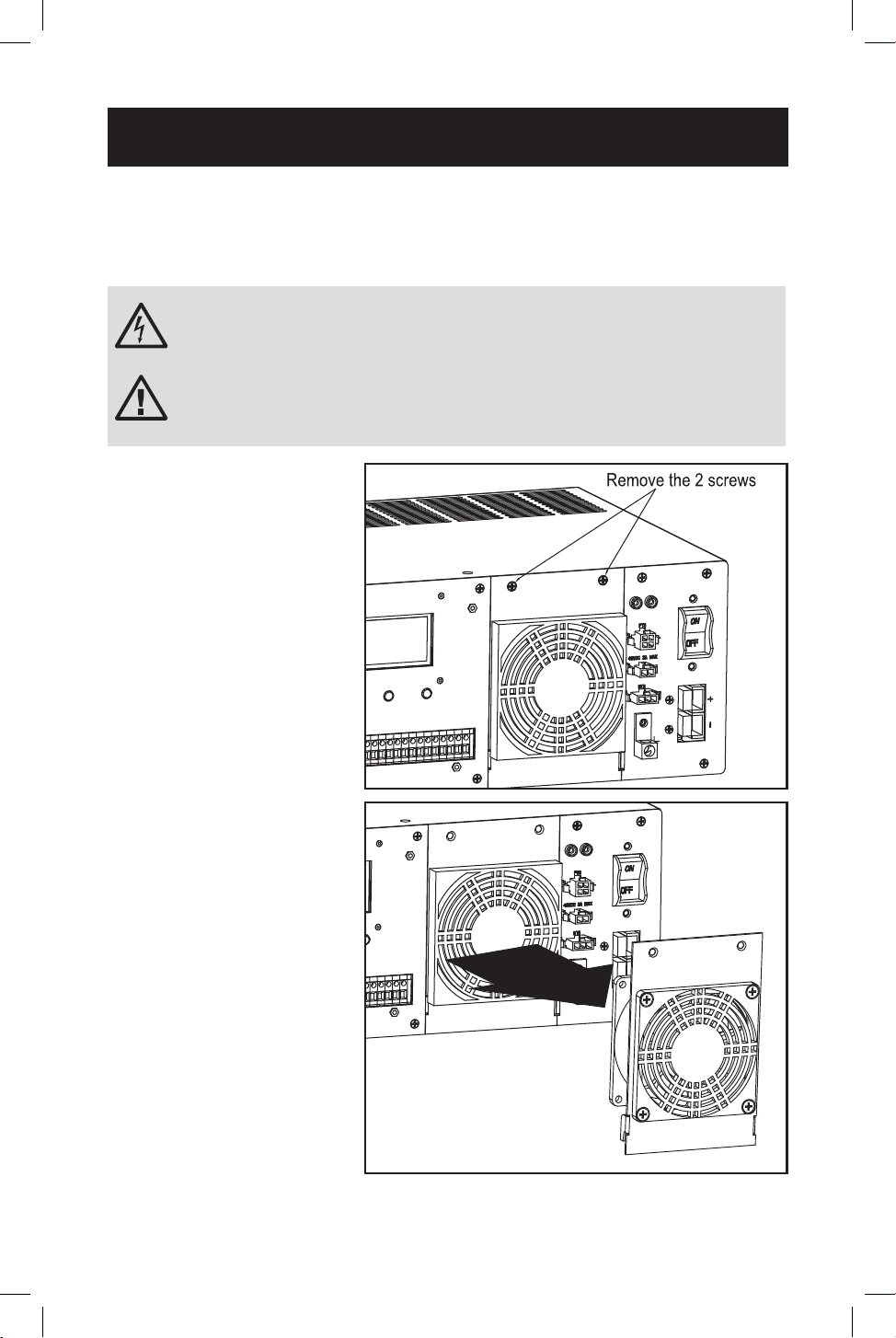
51
Fan Replacement
Under normal conditions, the original fan installation will last several years.
However, the internal fan assembly is replaceable.
CAUTION: The fan circuitry is not isolated from AC mains. Turn o
power to the UPS prior to fan replacement. Fan replacement must
be performed by qualied electrical service personnel.
ATTENTION: Before removing the fan assembly, note the fan
orientation. For proper installation and connectivity, the
replacement fan must remain in its original orientation.
6
6
Power UPS o. Remove
the two screws that
secure the fan panel to
the UPS.
Internal Fan Replacement
2
2
Remove the fan cover
and fan lter, then slide
the fan panel out and
up carefully to remove
it from the UPS, as the
internal fan power cable
is still attached to the
UPS main board.
3
3
Disconnect the fan
cable from the main
board fan connector.
1
1
2
2
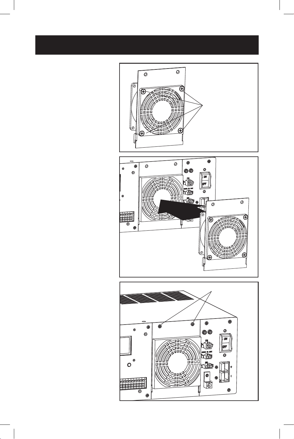
52
Internal Fan Replacement
Insert the 2 screws
9
9
Secure fan panel back
to the UPS with the
screws removed in
step 1.
Remove the 4 screws
4
4
Remove screws that
secure the fan to the
fan panel.
5
5
Install the replacement
fan and secure it to the
fan panel. Make sure
to pay attention to its
original orientation.
6
6
Attach the fan cable
to the main board fan
connector.
7
7
Reattach the fan panel
back to the UPS.
8
8
Check operation of fan
by powering ON the
UPS system.
4
4
7
7
9
9
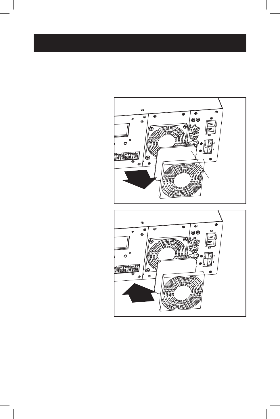
53
Internal Fan Replacement
Fan Filter Replacement
The internal fan is equipped with an air lter. To ensure proper operation, the lter
should be checked periodically for debris or contaminants that would reduce the
fan performance.
1
1
Use a small at-head
screwdriver to remove
fan lter cover from
front of UPS fan panel.
2
2
Clean lter cover.
3
3
Clean or replace
fan lter with one of
equivalent size and
material type.
4
4
Reinstall lter cover.
Fan filter
1
1
4
4

54
Storage and Service
Product Registration
Storage
To avoid battery drain, all connected equipment should be turned o and
disconnected from the UPS. Press the power button and disconnect the unit from
AC power. Your UPS will be completely turned o (deactivated) and will be ready
for storage. If you plan on storing your UPS for an extended period, fully recharge
the UPS batteries every 3 months. Plug the UPS into a live AC outlet, and allow the
batteries to recharge for 4 to 6 hours. If you leave your UPS batteries discharged
for a long period of time, they will suer a permanent loss of capacity.
Service
A variety of Extended Warranty and On-Site Service Programs are available from
Tripp Lite. For more information on service, visit tripplite.com/support.
Before returning your product for service, follow these steps:
1. Review the installation and operation procedures in this manual to ensure that
the service problem does not originate from a misreading of the instructions.
2. If the problem continues, do not contact or return the product to the dealer.
Instead, visit tripplite.com/support.
3. If the problem requires service, visit tripplite.com/support and click the Product
Returns link. From here you can request a Returned Material Authorization
(RMA) number, which is required for service. This simple on-line form will ask
for your unit’s model and serial numbers, along with other general purchaser
information. The RMA number, along with shipping instructions, will be emailed
to you. Any damages (direct, indirect, special or consequential) to the product
incurred during shipment to Tripp Lite or an authorized Tripp Lite service
center is not covered under warranty. Products shipped to Tripp Lite or an
authorized Tripp Lite service center must have transportation charges prepaid.
Mark the RMA number on the outside of the package. If the product is within
its warranty period, enclose a copy of your sales receipt. Return the product for
service using an insured carrier to the address given to you when you request
the RMA.
Visit tripplite.com/warranty today to register your new Tripp Lite product. You’ll be
automatically entered into a drawing for a chance to win a FREE Tripp Lite product!
*
* No purchase necessary. Void where prohibited. Some restrictions apply. See website for
details.

55
Regulatory Compliance
FCC Part 68 Notice (United States Only)
If your Modem/Fax Protection causes harm to the telephone network, the telephone com-
pany may temporarily discontinue your service. If possible, they will notify you in advance.
If advance notice isn’t practical, you will be notied as soon as possible. You will be advised
of your right to le a complaint with the FCC. Your telephone company may make changes
in its facilities, equipment, operations or procedures that could aect the proper operation
of your equipment. If it does, you will be given advance notice to give you an opportunity to
maintain uninterrupted service. If you experience trouble with this equipment’s Modem/Fax
Protection, please visit tripplite.com/support for repair/warranty information. The telephone
company may ask you to disconnect this equipment from the network until the problem has
been corrected or you are sure the equipment is not malfunctioning. There are no repairs
that can be made by the customer to the Modem/Fax Protection. This equipment may not
be used on coin service provided by the telephone company. Connection to party lines is
subject to state taris. (Contact your state public utility commission or corporation commis-
sion for information.)
FCC Notice, Class A
This device complies with part 15 of the FCC Rules. Operation is subject to the following
two conditions: (1) This device may not cause harmful interference, and (2) this device must
accept any interference received, including interference that may cause undesired operation.
Note: This equipment has been tested and found to comply with the limits for a Class A
digital device, pursuant to part 15 of the FCC Rules. These limits are designed to provide
reasonable protection against harmful interference when the equipment is operated in a
commercial environment. This equipment generates, uses, and can radiate radio frequency
energy and, if not installed and used in accordance with the instruction manual, may cause
harmful interference to radio communications. Operation of this equipment in a residential
area is likely to cause harmful interference in which case the user will be required to correct
the interference at his own expense.
WARNING: Changes or modications not expressly approved by the party responsible for
compliance could void the user’s authority to operate the equipment.
Equipment Attachment Limitations
(models with the Industry Canada label in Canada only)
NOTICE: The Industry Canada label identies certied equipment. This certication means
that the equipment meets the telecommunications network protective, operational and
safety requirements as prescribed in the appropriate Terminal Equipment Technical Require-
ments Document(s). The Department does not guarantee the equipment will operate to the
user’s satisfaction. Before installing this equipment, users should ensure that it is permissible
to be connected to the facilities of the local telecommunications company. The equipment
must also be installed using an acceptable method of connection. The customer should
be aware that the compliance with the above conditions might not prevent degradation of
service in some situations.
Repairs to certied equipment should be coordinated by a representative designated by
the supplier. Any repairs or alterations made by the user to this equipment, or equipment
malfunctions, may give the telecommunications company cause to request the user to dis-
connect the equipment.
Users should ensure for their own protection that the electrical ground connections of the
power utility, telephone lines and internal metallic water pipe system, if present, are con-
nected together. This precaution may be particularly important in rural areas. Caution: Users
should not attempt to make connections themselves, but should contact the appropriate
electric inspection authority, or electrician, as appropriate.

56
tripplite.com/support
23-05-123 93-397B_RevF
Regulatory Compliance
Regulatory Compliance Identication Numbers
For the purpose of regulatory compliance certications and identication, your Tripp Lite
product has been assigned a unique series number. The series number can be found on the
product nameplate label, along with all required approval markings and information. When
requesting compliance information for this product, always refer to the series number. The
series number should not be confused with the marking name or model number of the
product.
Tripp Lite has a policy of continuous improvement. Product specications are subject to
change without notice. Photos and illustrations may dier slightly from actual products.