ID TECH
10721 Walker Street, Cypress, CA 90630-4720
Tel: (714) 761-6368 Fax (714) 761-8880
www.idtechproducts.com support@idtechproducts.com
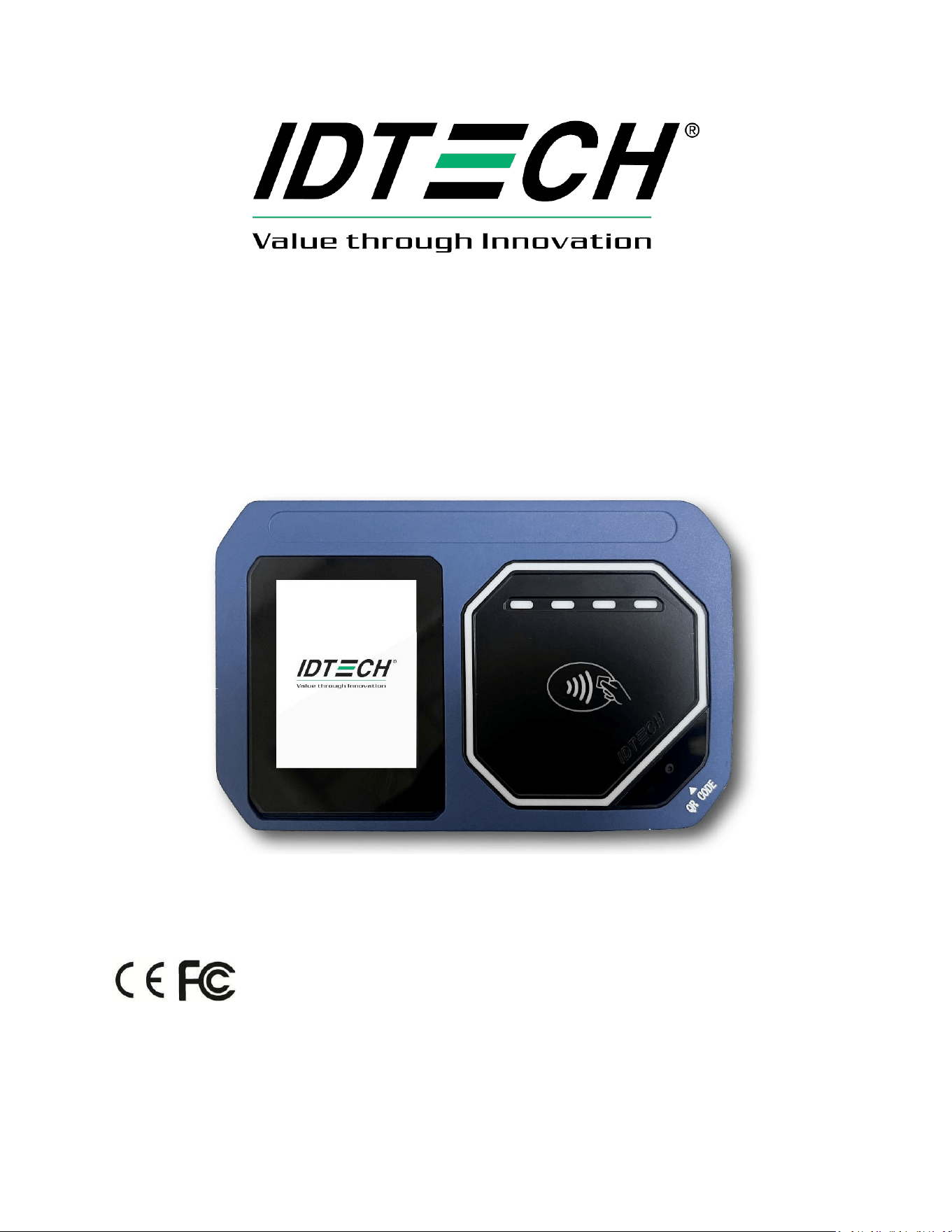
ID TECH VP7225 User Manual
80186502-001 Rev. A
12 February 2026
Copyright © 2025 ID TECH. All rights reserved.

VP7225 User Manual
Page | 2
ID TECH
10721 Walker St.
Cypress, CA 90630
This document, as well as the software and hardware described in it, is furnished under license and may
be used or copied online in accordance with the terms of such license. The content of this document is
furnished for information use only, is subject to change without notice, and should not be construed as
a commitment by ID TECH. Reasonable effort has been made to ensure the accuracy of information
provided herein. However, ID TECH assumes no responsibility or liability for any unintentional errors or
inaccuracies that may appear in this document.
Except as permitted by such license, no part of this publication may be reproduced or transmitted by
electronic, mechanical, recording, or otherwise, or translated into any language form without the
express written consent of ID TECH. ID TECH, Concierge, and ViVOpay are trademarks or registered
trademarks of ID TECH.
Warranty Disclaimer: The services and hardware are provided "as is" and "as-available" and the use of
the services and hardware is at its own risk. ID TECH does not make, and hereby disclaims, any and all
other express or implied warranties, including, but not limited to, warranties of merchantability, fitness
for a particular purpose, title, and any warranties arising from a course of dealing, usage, or trade
practice. ID TECH does not warrant that the services or hardware will be uninterrupted, error-free, or
completely secure.

VP7225 User Manual
Page | 3
FCC Regulatory Compliance
This device complies with Part 15 of the FCC Rules. Operation is subject to the following two conditions: (1) this device may not
cause harmful interference, and (2) this device must accept any interference received, including interference that may cause
undesired operation.
The user manual for an intentional or unintentional radiator shall caution the user that changes or modifications not expressly
approved by the party responsible for compliance could void the user’s authority to operate the equipment.
Note: The grantee is not responsible for any changes or modifications not expressly approved by the party responsible for
compliance. Such modifications could void the user’s authority to operate the equipment.
Note: This equipment has been tested and found to comply with the limits for a Class B digital device, pursuant to part 15 of
the FCC Rules. These limits are designed to provide reasonable protection against harmful interference in a residential
installation. This equipment generates and uses can radiate radio frequency energy and, if not installed and used in accordance
with the instructions, may cause harmful interference to radio communications. However, there is no guarantee that
interference will not occur in a particular installation. If this equipment does cause harmful interference to radio or television
reception, which can be determined by turning the equipment off and on, the user is encouraged to try to correct the
interference by one or more of the following measures:
• Reorient or relocate the receiving antenna.
• Increase the separation between the equipment and the receiver.
• Connect the equipment into an outlet on a circuit different from that to which the receiver is connected.
• Consult the dealer or an experienced radio/TV technician for help.
FCC RF Radiation Exposure Statement
This equipment complies with FCC radiation exposure limits set forth for an uncontrolled environment. To
comply with FCC RF Exposure compliance requirements, this grant applies only to Mobile Configurations. The antennas used for
the transmitter must be installed to provide a separation distance of at least 20cm from all persons and must not be co‐located
or operating in conjunction with any other antenna or transmitter.
ISED Warning statements
This device complies with Canada's licence-exempt RSSs. Operation is subject to the following two conditions:
(1) This device may not cause interference; and (2) This device must accept any interference, including interference that may
cause undesired operation of the device.
Le present appareil est conforme aux CNR d'Industrie Canada applicables aux appareils radio exempts de licence.
L'exploitation est autorisée aux deux conditions suivantes : (1) l'appareil ne doit pas produire de brouillage, et (2) l'utilisateur de
l'appareil doit accepter tout brouillage radioélectrique subi, même si le brouillage est susceptible d'encompromettre le
fonctionnement.
This equipment complies with IC RSS-102 radiation exposure limits set forth for an uncontrolled environment. This equipment
should be installed and operated with a minimum distance of 20cm between the radiator and any part of your body.
Pour se conformer aux exigences de conformité CNR 102 RF exposition, une distance de séparation d'aumoins 20 cm
doit êtremaintenue entre l'antenne de cet appareil ettoutes les personnes.
This Class B digital apparatus complies with Canadian ICES-003. Cet appareil numerique de la classe B est conforme a la norme
NMB-003 du Canada.
VP7225 User Manual
Page | 4
CE Caution
RF Exposure
This equipment complies with CE radiation exposure limits set forth for an uncontrolled environment. This equipment should
be installed and operated with minimum distance of 20cm between the radiator and your body.
EU DECLARATION OF CONFORMITY
Hereby, ID TECH declares that the radio equipment type VP7225 is in compliance with Directive 2014/53/EU.
The full text of the EU declaration of conformity is available at the following Internet address: https://idtechproducts.com/
The product is so constructed that it can be operated in at least one Member State without infringing applicable requirements
on the use of radio spectrum.
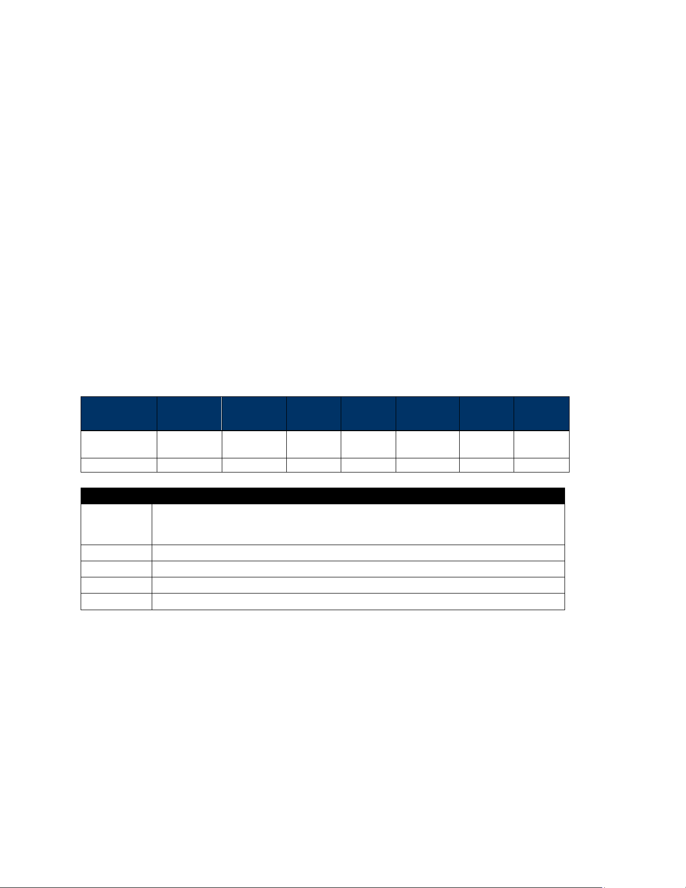
Notice for Operating Frequency and Output Power:
Feature
VP7225
NFC
2dBuA/m at 10m
BLE
Frequency(MHz)2402-2480
< 0dBm
Cautions and Warnings
Caution: The VP7225 should be mounted 1-2 feet away from other VP7225s. Can be adjusted based on lane
setup.
Warning: Avoid close proximity to radio transmitters which may reduce the capability of the reader.

VP7225 User Manual
Page | 5
Revision History
Date
Rev
Changes
By
02/12/2026
A
Initial Draft
YC/CB

VP7225 User Manual
Page | 6
Table of Contents
1. OVERVIEW ................................................................................................................................................................. 8
1.1. Universal SDK ..................................................................................................................................................... 8
1.2. Encryption .......................................................................................................................................................... 8
2. FEATURES ................................................................................................................................................................... 9
2.1. Certifications and Approvals ............................................................................................................................ 10
2.2. Regulatory ........................................................................................................................................................ 10
3. VP7225 SPECIFICATIONS .......................................................................................................................................... 11
3.1. USB Specifications ............................................................................................................................................ 12
3.2. Power Consumption ......................................................................................................................................... 13
3.2.1. Working mode ........................................................................................................................................... 13
3.2.2. Low Power Mode ....................................................................................................................................... 13
3.3. VP7225 Model Differences ............................................................................................................................... 13
3.4. VP7225 LTE, SAM, and SIM Connections .......................................................................................................... 14
3.4.1. Supported SAM Cards................................................................................................................................ 14
4. CABLE INTERFACES .................................................................................................................................................. 16
5. VP7225 LED AND SOUND STATE INDICATORS ......................................................................................................... 18
5.1. Tamper and Failed Self-Check Indicators ......................................................................................................... 19
6. VP7225 INSTALLATION ............................................................................................................................................ 20
6.1. Parts List ........................................................................................................................................................... 20
6.2. VP7225 Interface Connectors ........................................................................................................................... 20
6.3. Mounting the VP7225 ...................................................................................................................................... 20
6.4. VP7225 Hardware Connectors Guide ............................................................................................................... 22
6.4.1. Connecting to Host Systems ...................................................................................................................... 22
6.5. Communication via USB ................................................................................................................................... 23
6.6. Connecting to LTE ............................................................................................................................................. 23
6.6.1. Before You Begin ....................................................................................................................................... 23
6.6.2. Accessing the SAM Slots ............................................................................................................................ 24
6.6.3. Installing the SIM Card .............................................................................................................................. 26
6.6.4. Pairing the SIM Card ................................................................................................................................. 26
6.6.5. Enabling Cellular Functionality .................................................................................................................. 28
6.6.6. Configure Cellular TCP/IP Context (D3-09) ................................................................................................ 29
6.7. SAM (Secure Access Module) Support ............................................................................................................. 31
6.7.1. Performance Tip for SAM Transactions ..................................................................................................... 31
6.7.2. Installing SAM Cards ................................................................................................................................. 31
6.7.3. Protocol and Communication .................................................................................................................... 31
6.7.4. SAM Command Set .................................................................................................................................... 31
6.7.5. Example SAM Operation Flow ................................................................................................................... 31
6.8. Connecting to the Data Port ............................................................................................................................. 33
6.9. Installation Checklist ........................................................................................................................................ 33
6.9.1. Visual Inspection ....................................................................................................................................... 33
6.9.2. Installation Procedures.............................................................................................................................. 33
6.9.3. Recommendations ..................................................................................................................................... 33
6.10. Using the VP7225 to Make a Purchase........................................................................................................... 34
6.10.1. Presenting Cards or NFC Phones ............................................................................................................. 34
6.10.2. Making a Purchase .................................................................................................................................. 35
6.11. Installation Points ........................................................................................................................................... 35
7. VP7225 CONFIGURATION SETTINGS ........................................................................................................................ 36
7.1. Configuring Ethernet Settings .......................................................................................................................... 36
7.1.1. Configuring Ethernet Settings with Low-Level Commands ....................................................................... 36
Configuring BLE Settings .......................................................................................................................................... 40
7.1.2. Configuring BLE with Low-Level Commands ............................................................................................. 40

VP7225 User Manual
Page | 7
7.2. Configuring LTE Settings ................................................................................................................................... 42
7.2.1. Configuring LTE Settings with Low-Level Commands ................................................................................ 42
7.3. Configuring System Settings ............................................................................................................................. 49
7.3.1. Configuring System Settings with Low-Level Commands .......................................................................... 49
8. RF INTERFERENCE .................................................................................................................................................... 52
9. UPGRADING FIRMWARE .......................................................................................................................................... 53
9.1. Preparation ....................................................................................................................................................... 53
9.2. Loading Files onto the Reader .......................................................................................................................... 53
9.3. Updating K81 Bootloader ................................................................................................................................. 54
9.4. Updating K81 Firmware .................................................................................................................................... 55
9.5. Updating K81 Device Tree Firmware ................................................................................................................ 56
9.5.1. Determining the Correct Device Tree Firmware to Use ............................................................................. 56
9.5.2. Updating the Device Tree Firmware .......................................................................................................... 58
9.6. Updating RT1050 Bootloader ........................................................................................................................... 59
9.7. Updating RT1050 Firmware .............................................................................................................................. 60
9.8. Updating RT1050 Device Tree Firmware .......................................................................................................... 61
10. DECOMMISSIONING SRED DEVICES....................................................................................................................... 62
11. TROUBLESHOOTING .............................................................................................................................................. 63
11.1. LTE Diagnostic Troubleshooting ..................................................................................................................... 64
11.1.1. Step 1: Check the Firmware and Device Tree Versions ............................................................................ 64
11.1.2. Step 2: Check the Cellular Configuration ................................................................................................. 64
11.1.3. Step 3: Check the LTE Working Mode...................................................................................................... 64
11.1.4. Step 4: Check the Current SIM Card Slot Settings .................................................................................... 65
12. AVOIDING DEVICE TAMPER ISSUES ....................................................................................................................... 66
12.1. Device Handling Best Practices ...................................................................................................................... 66
12.2. ID TECH Support ............................................................................................................................................. 66
13. FOR MORE INFORMATION..................................................................................................................................... 67

VP7225 User Manual
Page | 8
1. Overview
The ID TECH VP72225 is a compact, standalone contactless reader, designed to support contactless EMV
transactions based on ISO 18092, ISO 14443 Type A/Type B/MiFare compatible cards, fobs and tags, as
well as NFC phones. The VP7225 is a single piece device including controller and antenna.
The VP7225 supports USB and serial RS-232 host communication using the NEO 3 protocol defined in
the NEO 2 Interface Developers Guide. This comprehensive guide describes all the firmware commands
and other features available in NEO 3-series devices; it is the authoritative source for technical
information of interest to systems integrators. (Contact your ID TECH representative to obtain a copy of
this guide, which is available only on request.) See this guide when controlling the VP7225 through
firmware commands sent directly over a serial port.
1.1. Universal SDK
A feature-rich Windows-based Universal SDK is available to aid rapid development of applications that
talk to VP7225. The SDK is available for the C# language on Windows and comes with sample code for
demo apps. To obtain the SDK and other useful utilities, demos, and downloads, be sure to check the
Downloads link on the ID TECH Knowledge Base (no registration required).
1.2. Encryption
VP7225 readers support industry-standard Triple DES or AES encryption, with DUKPT-based key
management (per ANSI X9.24). Encryption can be configured to occur with a data variant as desired. ID
TECH operates a certified Key Injection Facility, capable of injecting your unit(s) with any required keys.
Consult your ID TECH representative to learn about all available options involving key injections.

VP7225 User Manual
Page | 9
2. Features
The VP7225 supports the following transaction types:
• ISO/IEC 14443 Type A and B
• ISO 18092
• ISO 21481 (PCD & NFC)
• Suitable for transit, kiosks, parking and various other unattended and attended verticals.
• Consumer Intuitive: Equipped with LEDs and sound to provide visual and audible cues to enable
smooth and seamless transactions.
• Secure: Provides highly secure transactions whether financial, pre-paid, loyalty, or gift cards.
Data is encrypted at the time of the transaction and never travels in clear-text form.
• Self-contained antenna
• VP7225 is certified with Visa Ready for Transit
This document assumes that users are familiar with their host systems and all related functions.

VP7225 User Manual
Page | 10
2.1. Certifications and Approvals
VP7225 supports the following contactless payment applications and mobile payments:
• American Express ExpressPay 4.1
• Discover DPAS 2.0
• Felica
• Interac Flash v1.8
• JCB
• MasterCard PayPass/MChip 3.1.4
• UPI
• Visa VCPS 2.2 and VISA VCTKS 1.1
• Mifare
• Apple Pay, Google Pay, Samsung Pay, & other Mobile Wallets
• Apple VAS & Google SmartTap mobile Loyalty Programs
• AT&T Trendi
• PTCRB/GCF Report
2.2. Regulatory
• CE Mark
• UL certified
• ROHS2 and REACH
• TQM Certification
• Japan Telec/VCCI
VP7225 User Manual
Page | 11
3. VP7225 Specifications
Hardware
MTBF
500,000 hours based on Telcordia Technologies SR-332 modeled at 40° C.
Transmitter Frequency
13.56 MHz +/- 0.01%
Transmitter Modulation
ISO 14443-2 Type A
Rise/Fall Time: 2-3 µsec. Rise, < 1 µsec fall ISO 14443-2 Type B
Rise/Fall Time: < 2 µsec. each; 8% - 14% ASK ISO 18092
ISO 21481 (PCD & NFC)
Receiver Subcarrier
Frequency
847.5 KHz
Receiver Subcarrier
Data
ISO 14443-2 Type A: Modified Manchester ISO 14443-2 Type B: NRZ-L, BPSK
ISO 18092
ISO 21481 (PCD & NFC)
Typical Read Range
Up to 6 cm (2.3 inches)
Physical
Length
138.4 mm
Width
88.4 mm
Depth
37.2 mm
Environmental
Operating Temperature
0 C to 50° C , max change of 10° C per hour
Storage Temperature
-30° C to 85° C [non-condensing]
Operating Humidity
10% to Water-resistant 90% non-condensing, maximum 95%
Storage Humidity
10% to 90% non-condensing, duration 3 months
Transit Humidity
5% to 95% non-condensing, duration 1 week
Operating Environment
Water resistant for indoor and semi outdoor use
IK Rating
IK 6
IP Rating
IP 65
ESD
+/-8KV Contact and +/- 12KV Air
Electrical
Reader Input Voltage
+5V (USB port-powered; RS-232 requires power supply)
Working Current Rated
power
<2A
<10w
Battery (for real-time
clock)
CR2032 20mm x 3.2mm, 230mAh ("coin" battery), lifetime 5 years

VP7225 User Manual
Page | 12
3.1. USB Specifications
USB C Female
Power Supply Requirement
Voltage (V)
4.75 to 5.25
Current (A)
2
Power (W)
10
USB
Version
2.0
Protocol
USB Standard
USB Speed (Full speed or High Speed)
High Speed
PD Support
Not supported
USB Role( Host or Device )
Device
OTG
Not supported
Pin Out
View Sheets
USB Power Delivery
Mode of Operation
Voltage
Max Current
Max Power
USB 1.x / USB 2.0
5 V
0.5 A
2.5 W
USB 3.X
5 V
0.9 A
4.5 W
USB-C (Standard)
5 V
3 A
15 W
USB-C (PD)
5 - 20 V
5 A
25W - 100W
VP7225 Pin Out
A1
GND
A2
AP_RS232_TX1
A3
3] AP_RS232_RTS1
A4
VBUS_A4_B9
A5
CC1
A6
USB1_AP_DP
A7
USB1_AP_DN
A8
LINEOUT_L
A9
VBUS_B4_A9
A10
ETHERNET_RXN
A11
ETHERNET_RXP
A12
GND
B1
GND
B2
ETHERNET_TXP
B3
ETHERNET_TXN
B4
VBUS_B4_A9
B5
MIC_DET
B6
UART5_RX
B7
UART5_TX
B8
LINEOUT_R
B9
VBUS_A4_B9
B10
AP_RS232_CTS1
B11
AP_RS232_RX1
B12
GND
VP7225 User Manual
Page | 13
3.2. Power Consumption
Note the following information about VP7225 power consumption.
3.2.1. Working mode
• Contactless transaction mode maximum power consumption is <2A/5V.
• When the VP7225’s RF is inactive due to no connection to the host device, the maximum power
consumption is <200mA/5V.
3.2.2. Low Power Mode
VP7225 low power mode is only supported with RS-232 5VDC input. Note that low power mode is NOT
supported via USB.
• Standby mode power consumption is 110mA/5V. VP7225 units can wake up via RS-232 with a
wake-up time of <1s.
• Sleep mode power consumption is 100mA/5V. VP7225 units can wake up via RS-232 with a
wake-up time of <8s.
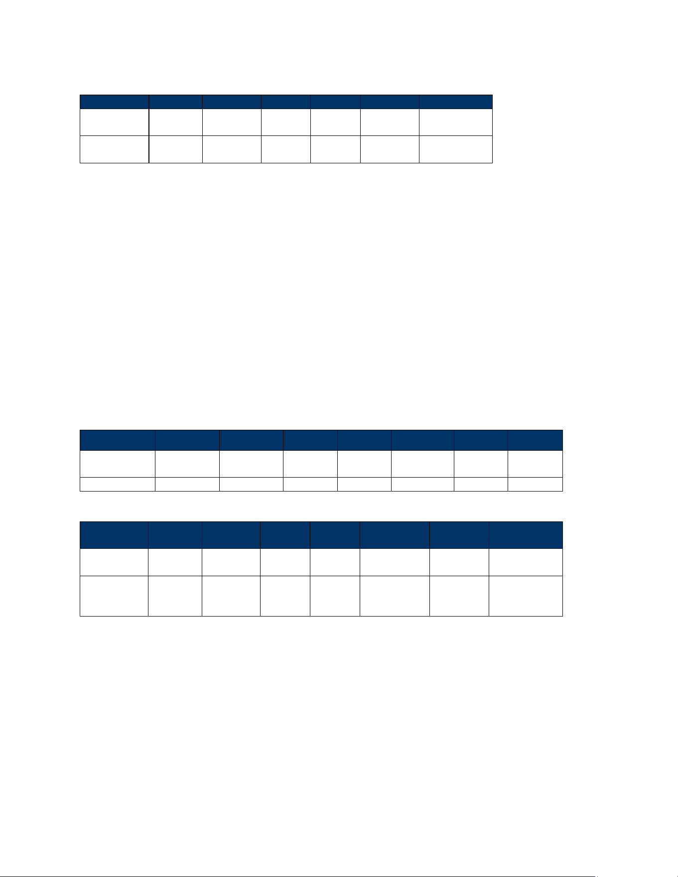
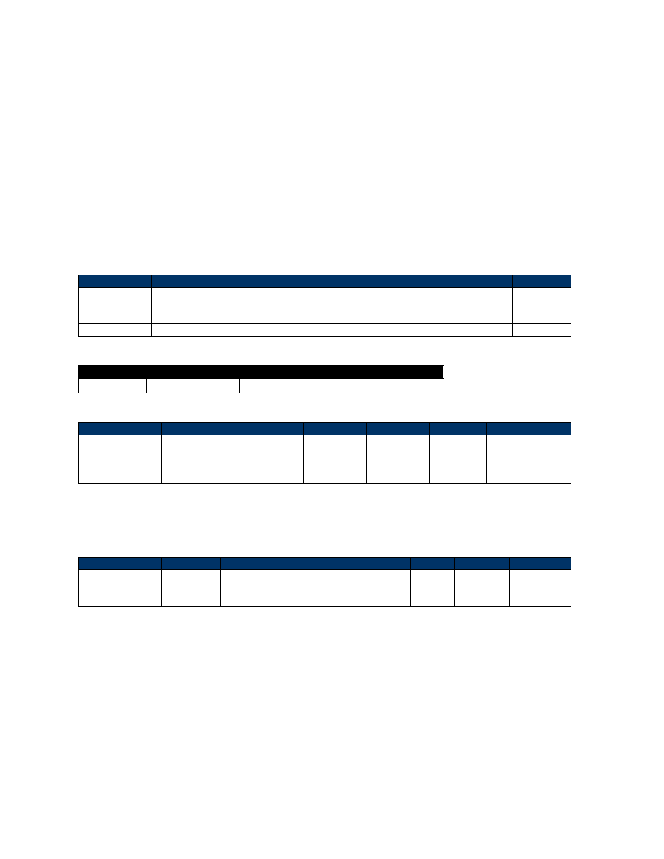
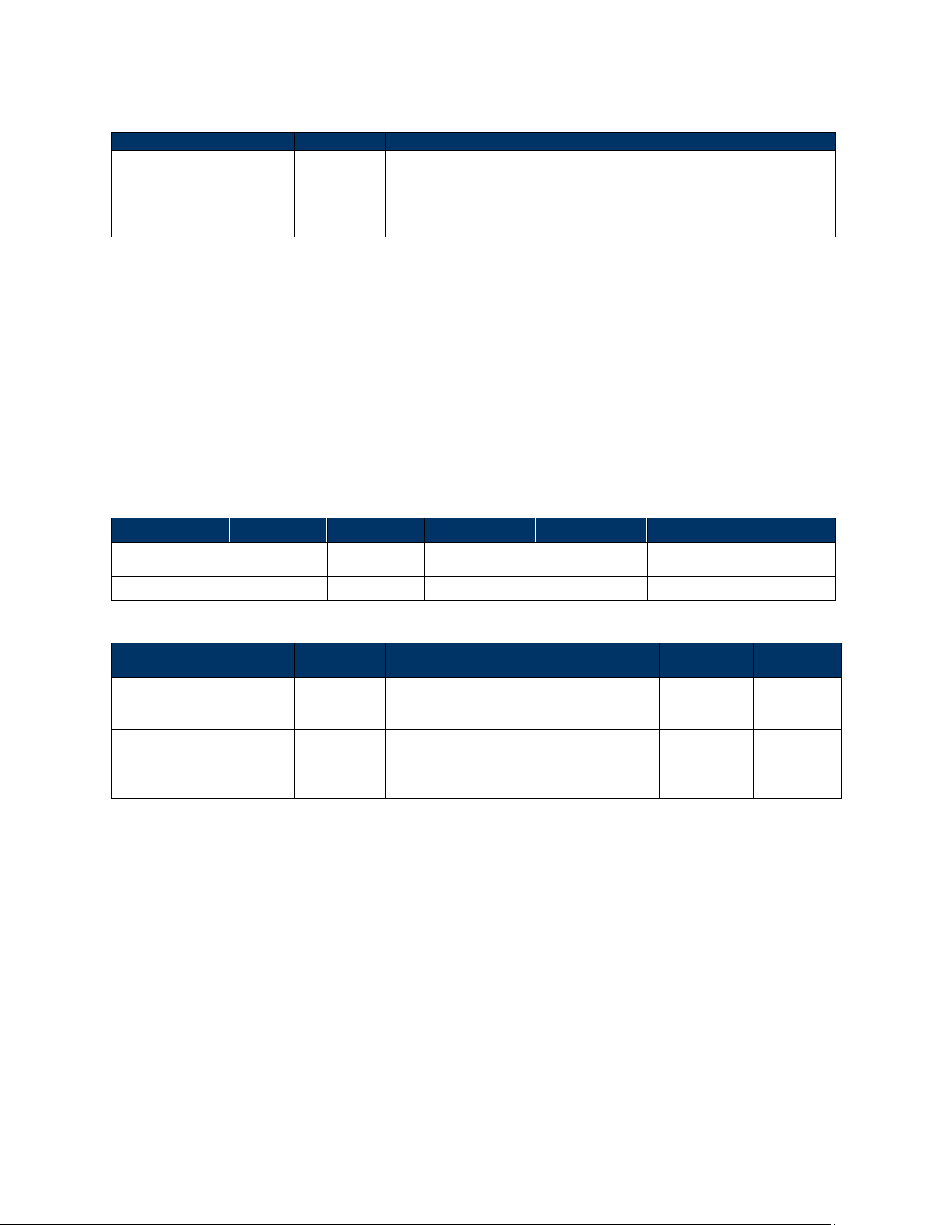
3.3. VP7225 Model Differences
P/N : ID72-808HF; ID72-808HFD;ID72-008HF; ID72-008HFD;ID72-800HF; ID72-800HFD;ID72-000HF;
ID72-000HFD
Model No:
camera
Ethernet
Others
ID72-808HF; ID72-808HFD (This two models just have
difference key)
YES
YES
All the
same
ID72-008HF; ID72-008HFD (This two models just have
difference key)
NO
YES
VP7225 User Manual
Page | 14
ID72-800HF; ID72-800HFD (This two models just have
difference key)
YES
NO
ID72-000HF; ID72-000HFD (This two models just have
difference key)
NO
NO
The key is a software key which is related to the transaction.
The Ethernet has no related components on the PCBA, it is turned on/off by software.
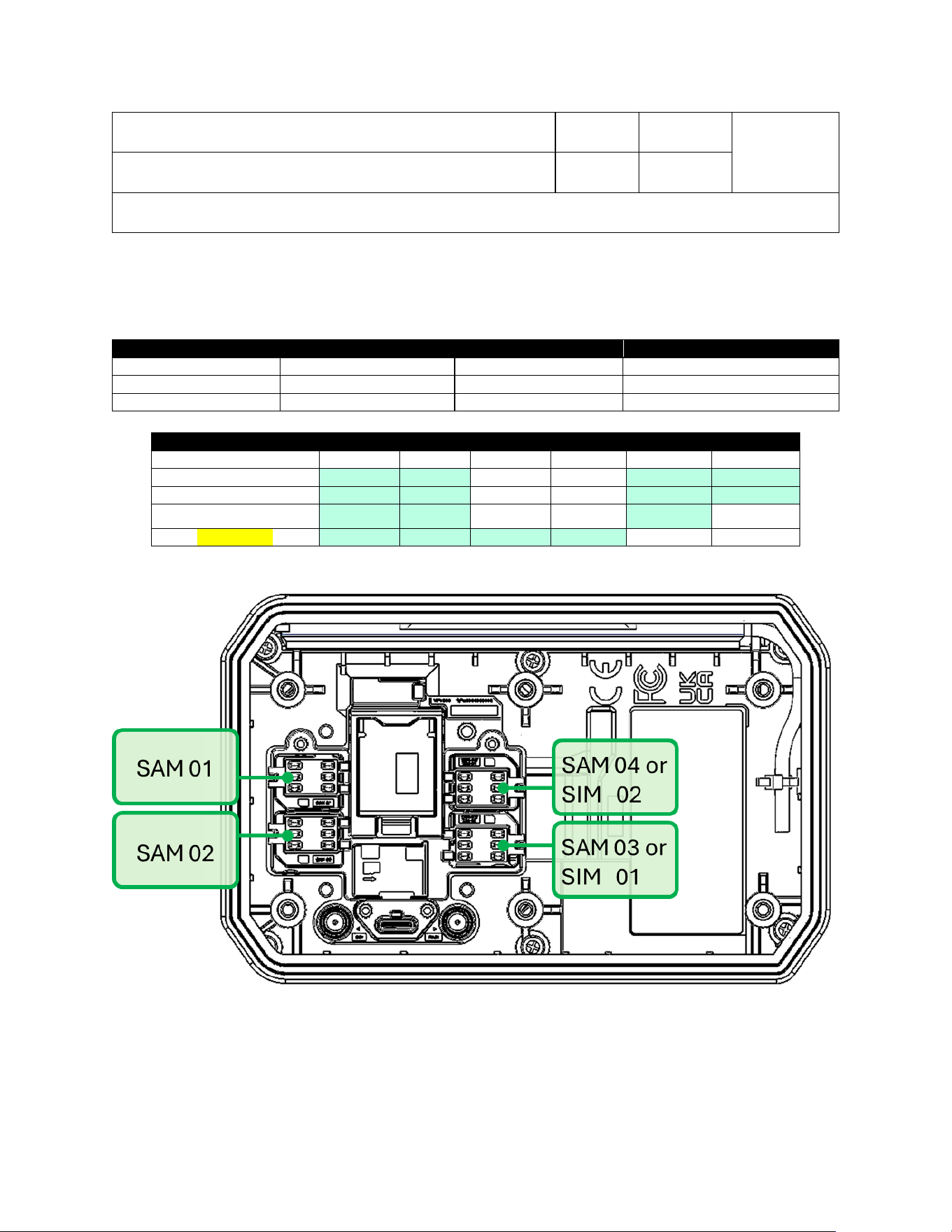
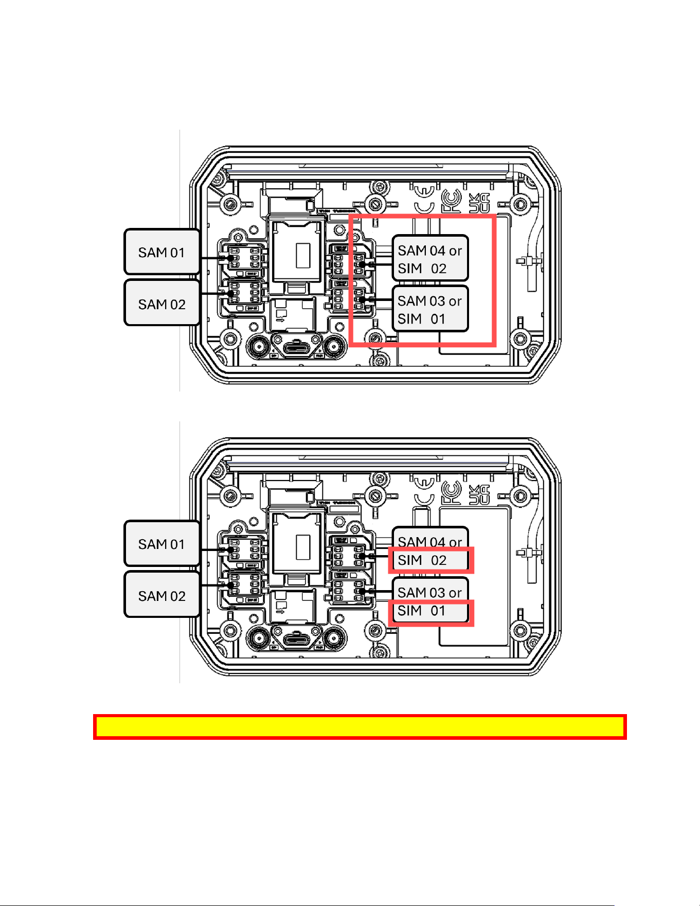
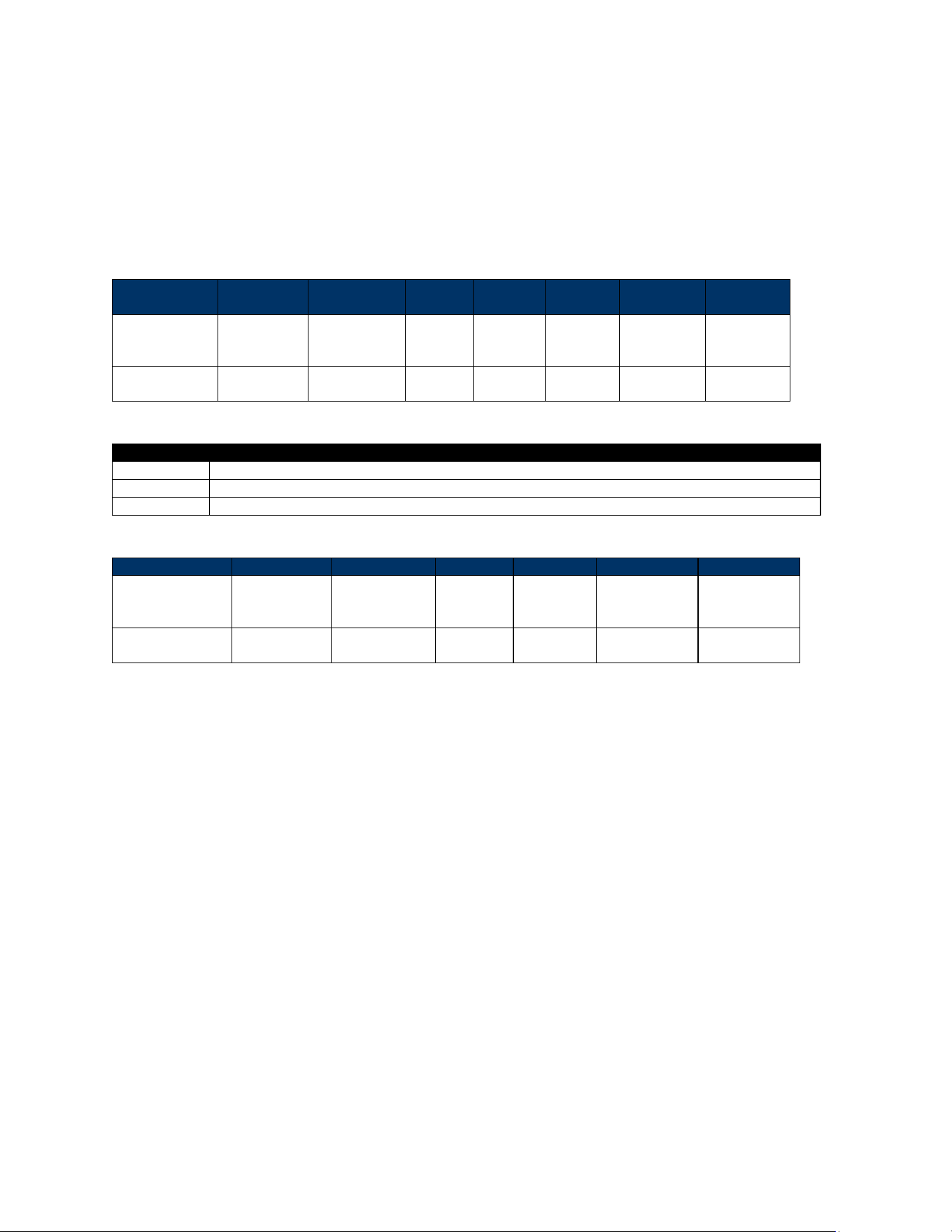
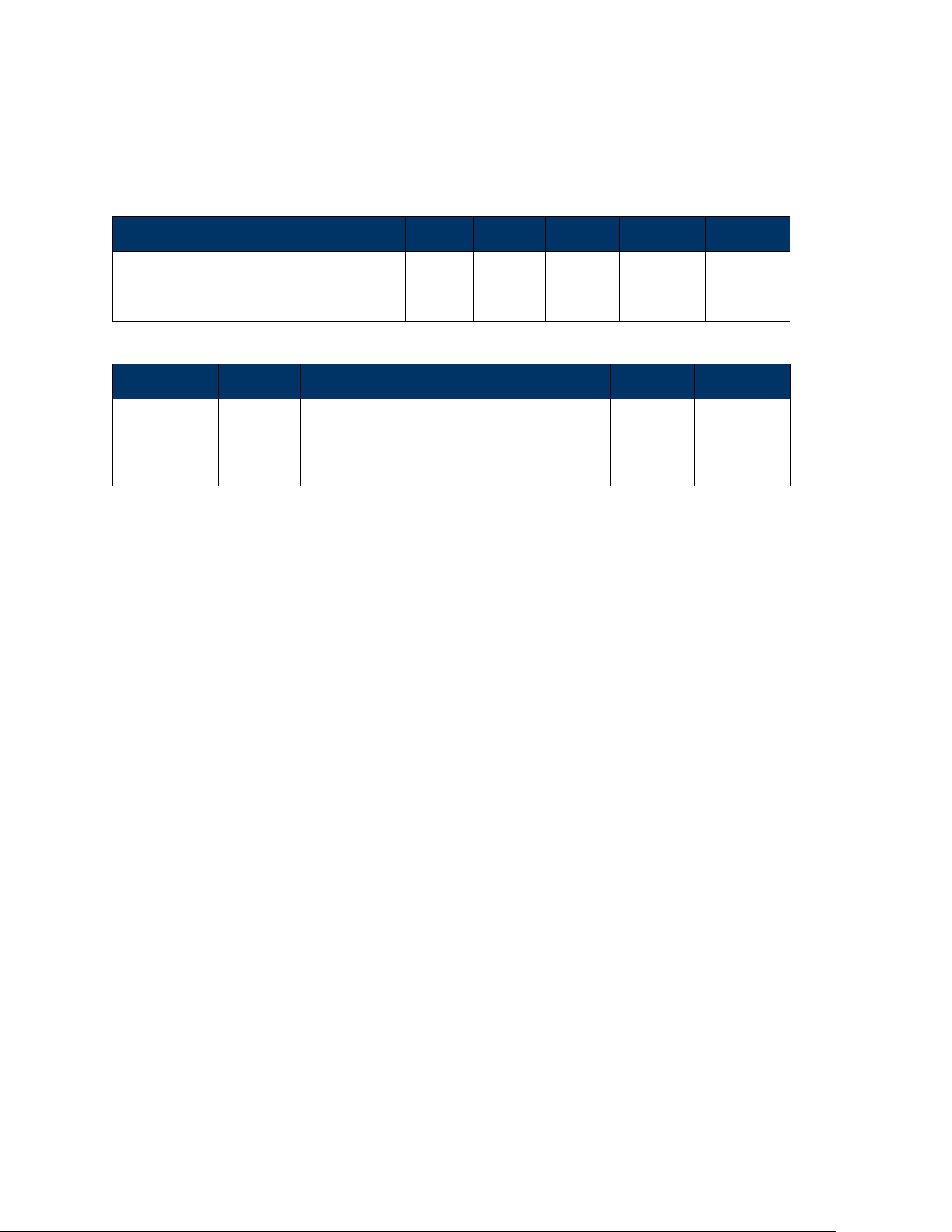
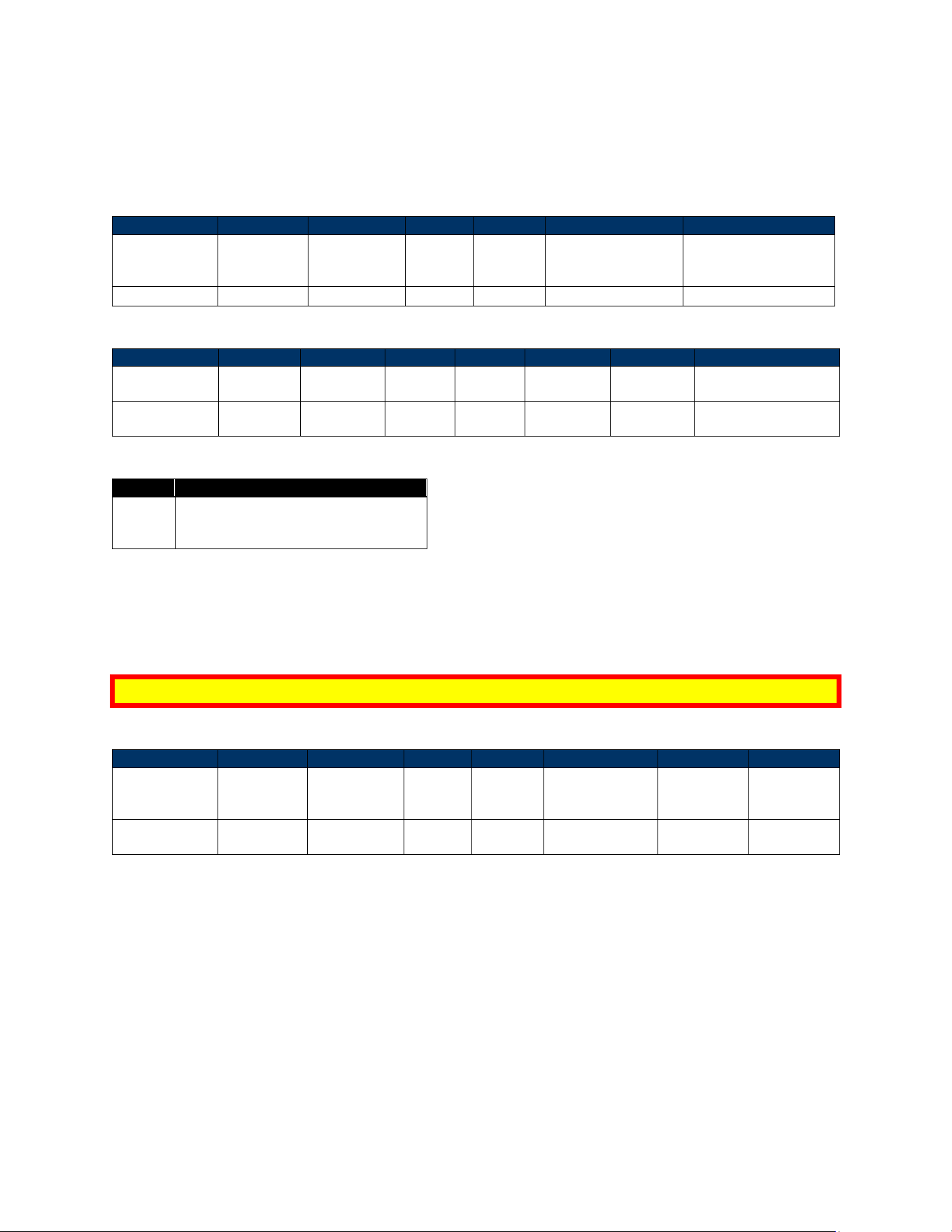
3.4. VP7225 LTE, SAM, and SIM Connections
The tables and diagram below illustrate VP7225 LTE, SAM, and SIM connections.
P/N
Region/Operator
SIM card slot
Antenna connection
ID72-818HJD
North America
SIM1/SIM2
Main/DIV
ID72-838HJD
EMEA
SIM1/SIM2
Main/DIV
ID72-868HJD
Japan
SIM1
Main
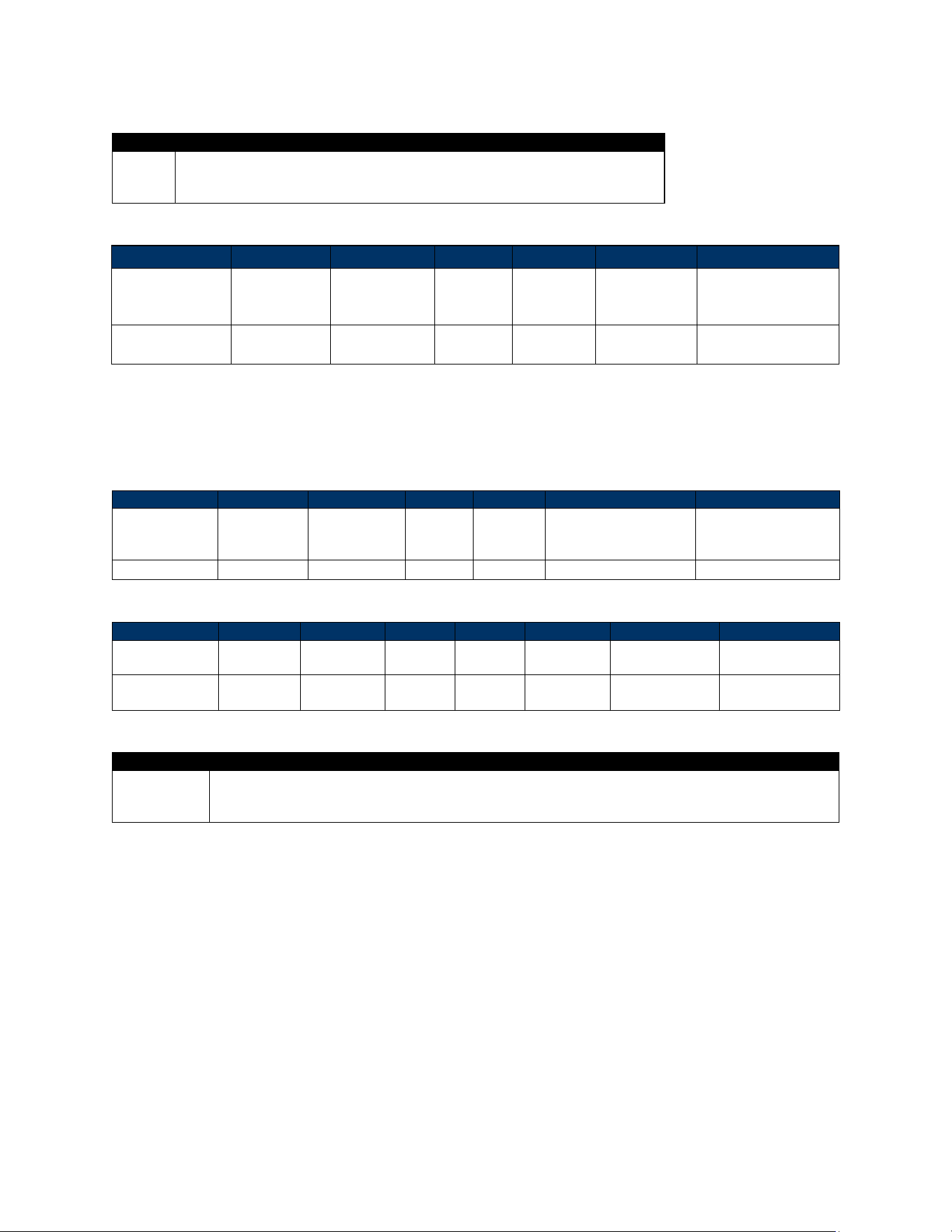
P/N
SAM card slot
SIM card slot
SAM1
SAM2
SAM3
SAM4
SIM1
SIM2
ID72-818HJD
✓
✓
X
X
✓
✓
ID72-838HJD
✓
✓
X
X
✓
✓
ID72-868HJD
✓
✓
X
X
✓
X
ID72-808HFD
✓
✓
✓
✓
X
X
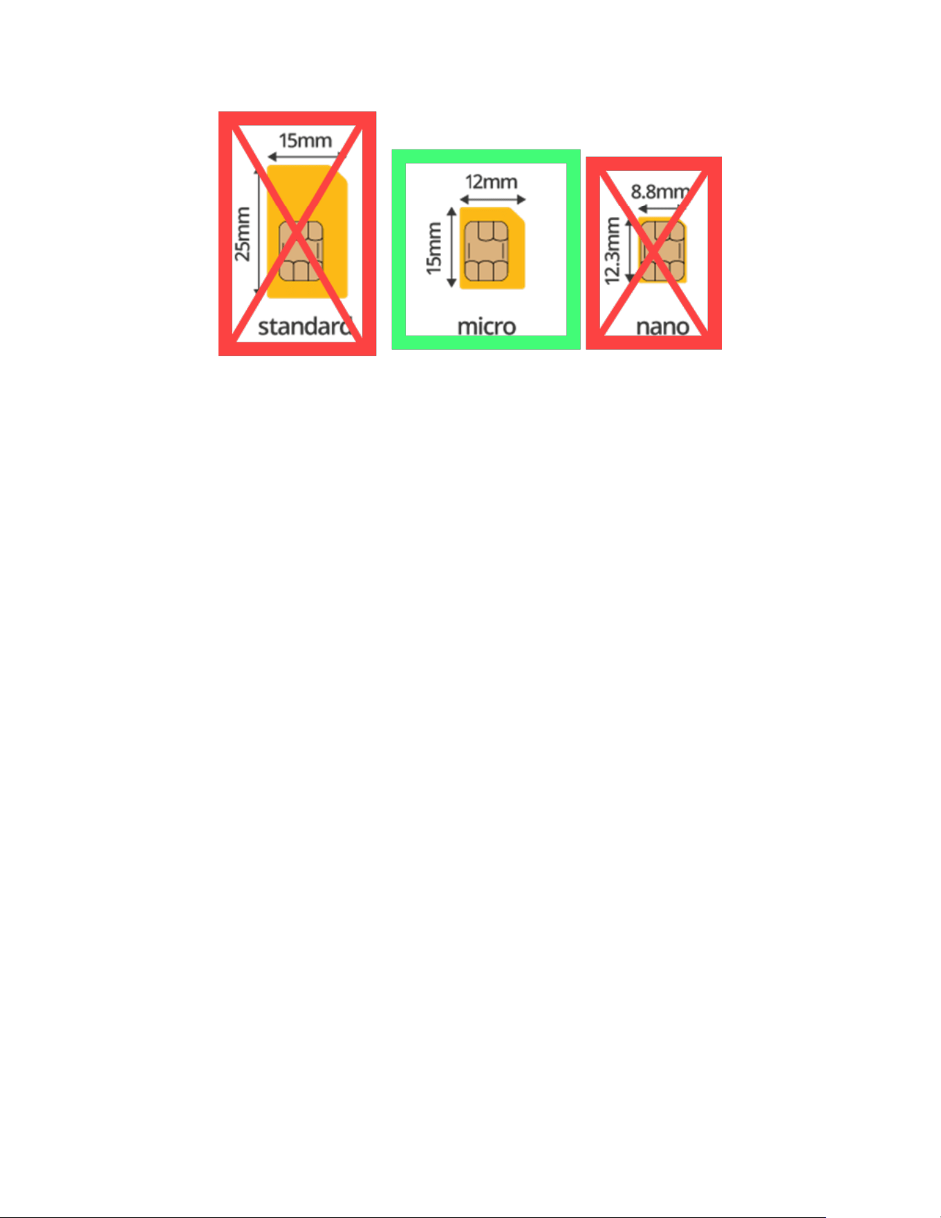
3.4.1. Supported SAM Cards
VP7225 readers use MicroSAM cards, illustrated below:
VP7225 User Manual
Page | 15
VP7225 User Manual
Page | 16
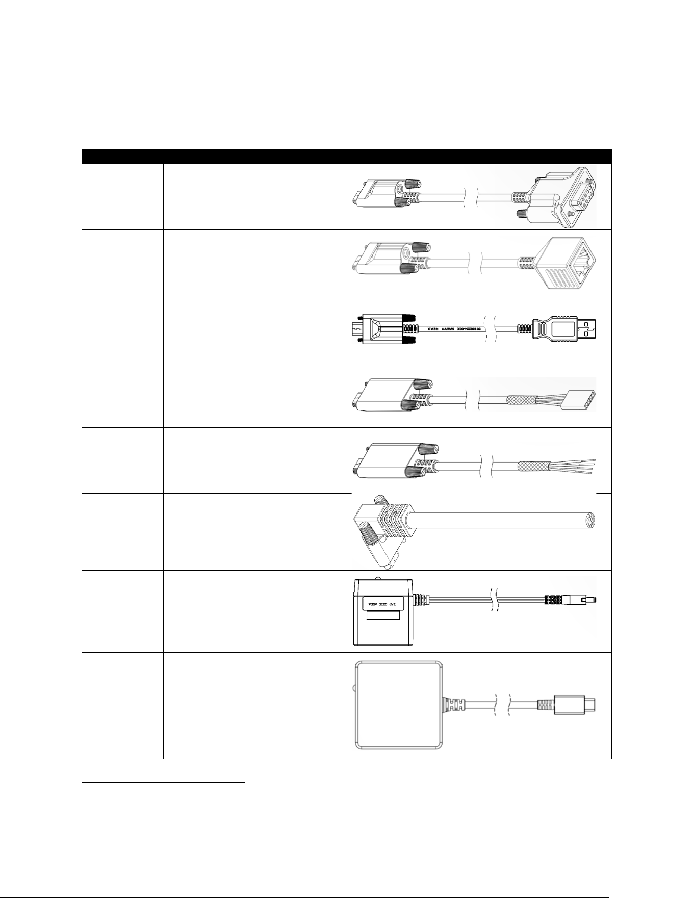
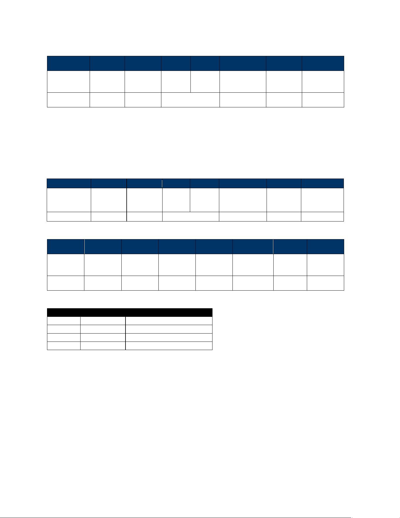
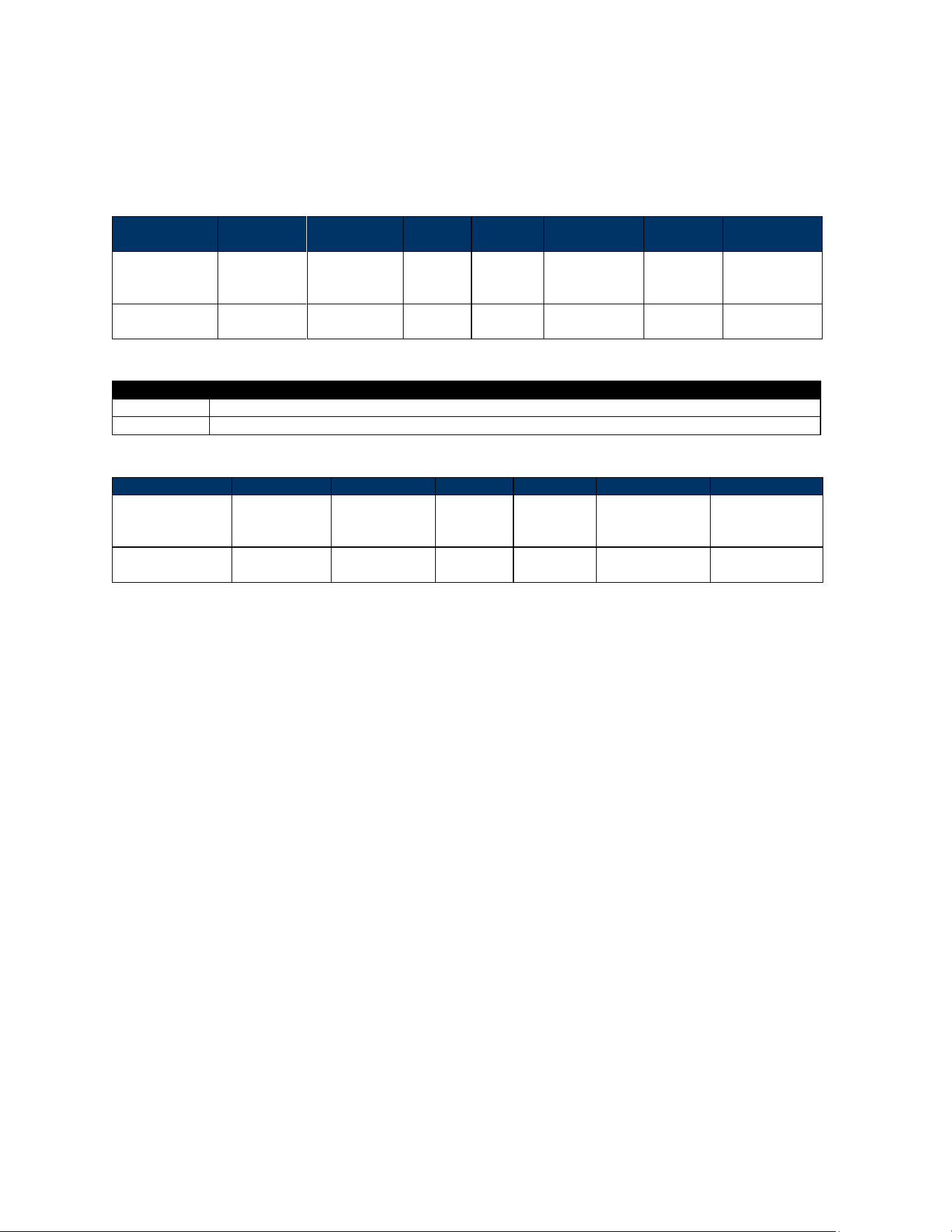
4. Cable Interfaces
VP7225 readers use a USB-C connector to connect to the host device. Cables connect to multiple types
of communication ports, as shown below.
Input
Output
P/N
Part
USB-C (IDT)
1
RS232
(DB9) cable
80185224-001
USB-C (IDT)
1
Ethernet
(RJ45) cable
80186228-001
USB-C (IDT)
1
USB-A cable
80186214-001
USB-C (IDT)
UART (IDT)
80185226-001
USB-C (IDT)
UART (IDT)
80185226-002
USB-C (IDT)
(Right Angle)
Cable end
only
80186227-001
DC Jack
US Plug
AC0005R-28
USB-C
(Standard)
US Plug
AC0005R-29
1
Note that cables 80185224-001, 80186228-001, and 80186214-001 all require a power adapter (P/N AC0005R-
28).
VP7225 User Manual
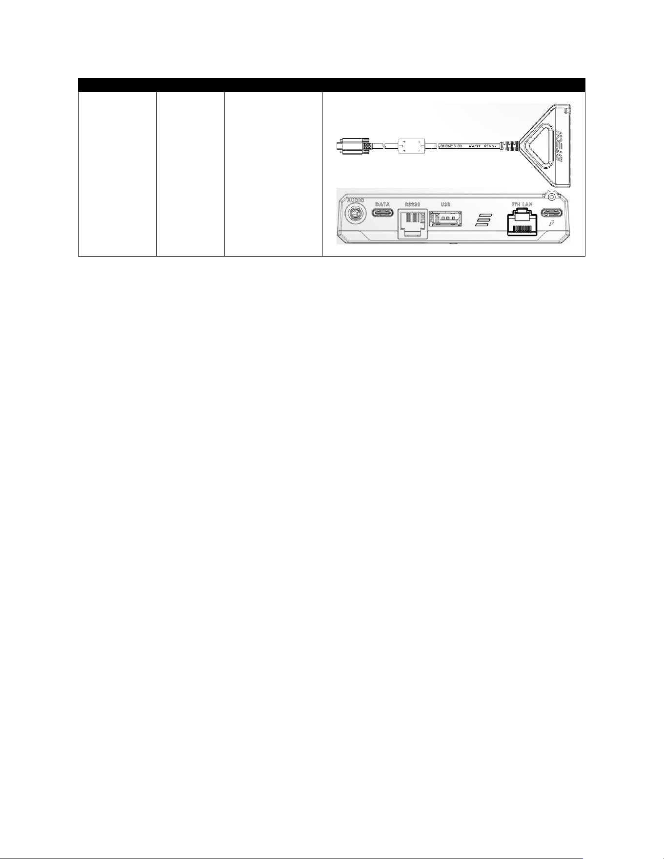
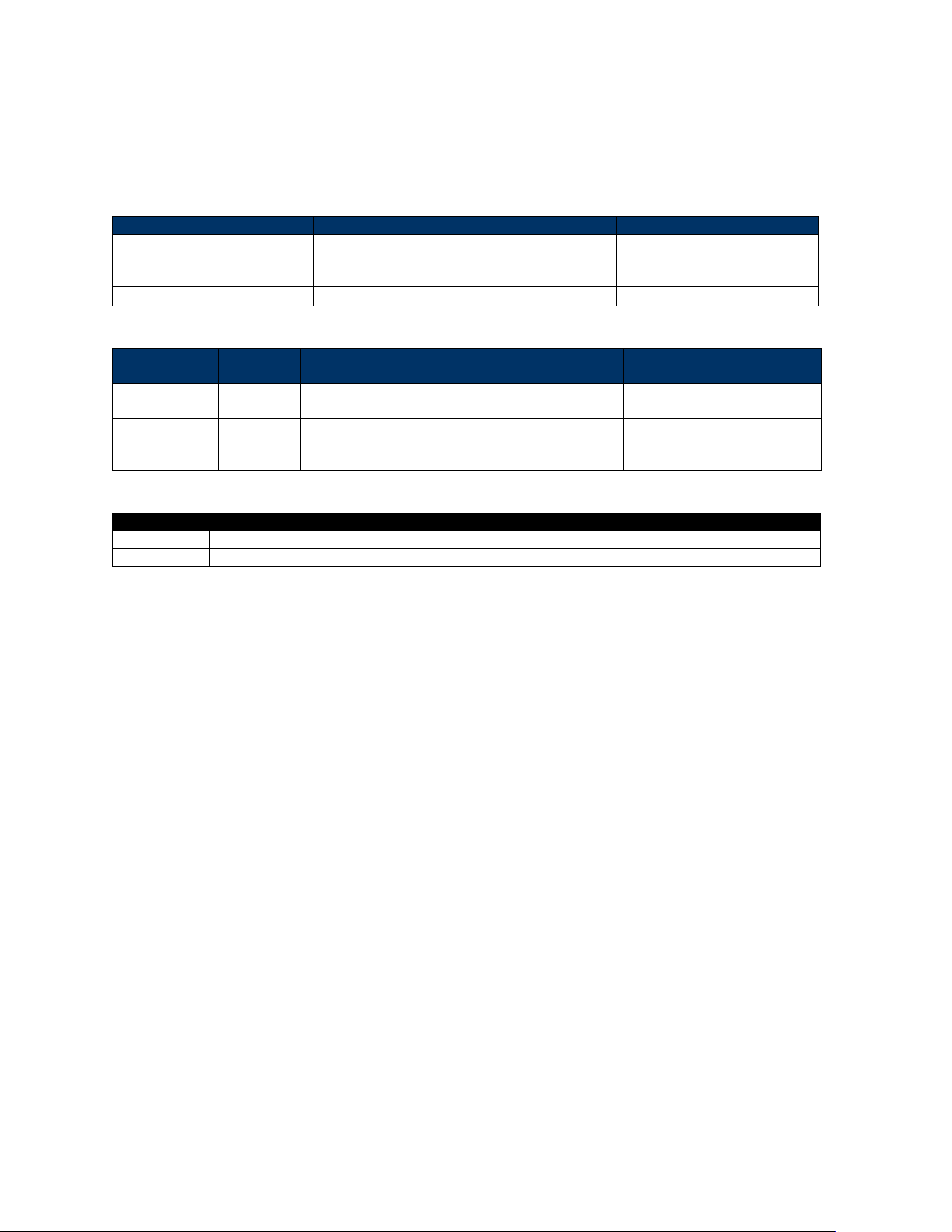
Page | 17
Input
Output
P/N
Part
USB-C (IDT)
Multi-port
80186213-001

VP7225 User Manual
Page | 18
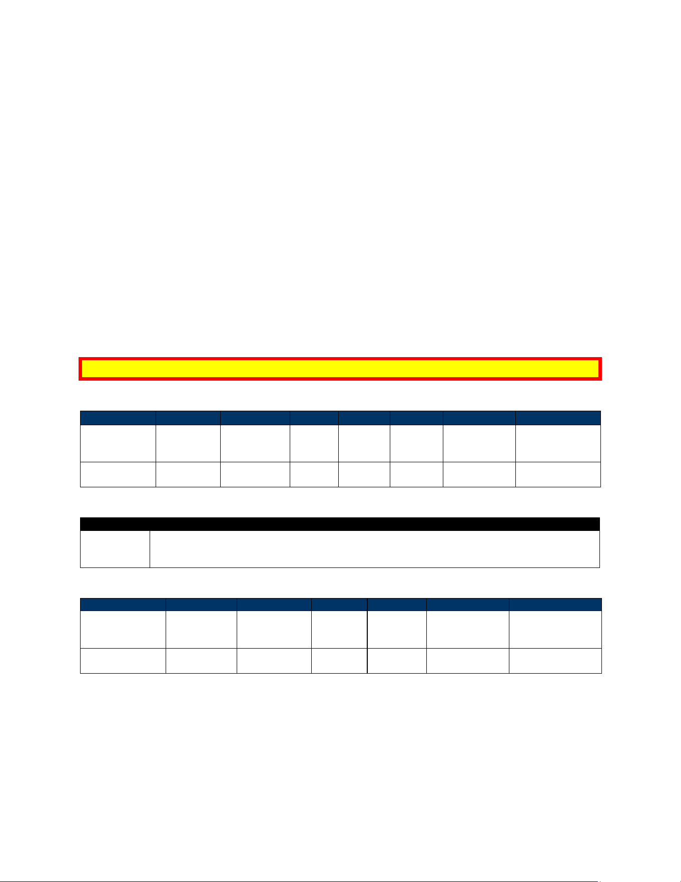
5. VP7225 LED and Sound State Indicators
The VP7225 uses the following LEDs and sounds to indicate various statuses, including power
management, transactions, and security.
Device State
LED1
LED2
LED3
LED4
Beeper
2
Device FW, certificates,
or keys self-test failed.
○
off
○
off
○
off
●
blink
Beeps
Device Tampered
○
off
○
off
○
off
●
blink
Beeps
Device Deactivated
○
off
○
off
○
off
●
blink
Beeps
Device Activated
3
○
off
○
off
○
off
●
on
Off
Device Key Missing
4
●
blink
●
blink
●
blink
●
blink
Off
Ready for Transaction
●
blink
○
off
○
off
○
off
Off
Transaction Started
5
●
on
○
off
○
off
○
off
Off
Transaction Successful
6
●
on
●
on
●
on
●
on
Beeps
Once
Transaction Failed
○
off
○
off
○
off
○
off
Beeps
Twice
2
Note that “beeps” indicates constant beeping unless the description includes a specific number of beeps (such as “twice”).
3
The device has loaded certificates successfully and is activated.
4
The device only has LCL-KEK; the required key is not injected.
5
The transaction has started and the device is waiting to read a card.
6
LEDs remain on for 1000ms.
VP7225 User Manual
Page | 19
5.1. Tamper and Failed Self-Check Indicators
The VP7225 displays the following indicators when it has been tampered or has any of the other
following internal issues, such as an expired certificate, missing key, or similar fault discovered during a
self-check.
Indicator
Tampered Status
LED
LED4 blinks red
Buzzer
Alarm tone
VP7225 User Manual
Page | 20
6. VP7225 Installation
This section provides information on how to install the VP7225 on a kiosk.
6.1. Parts List
Verify that you have the following hardware for the installation of the VP7225:
• VP7225
• Cables (sold separately)
o RS-232: Use a cable with P/N to 80185224-001 or equivalent 5VDC powered cable.
o USB: Use a USB-A to USB-C cable with P/N 80186214-001 (the VP7225 unit, in this
case, would be port-powered).
o Ethernet cable: P/N 80186228-001; using an ethernet cable requires 5VDC power
adapter P/N AC0005R-28.
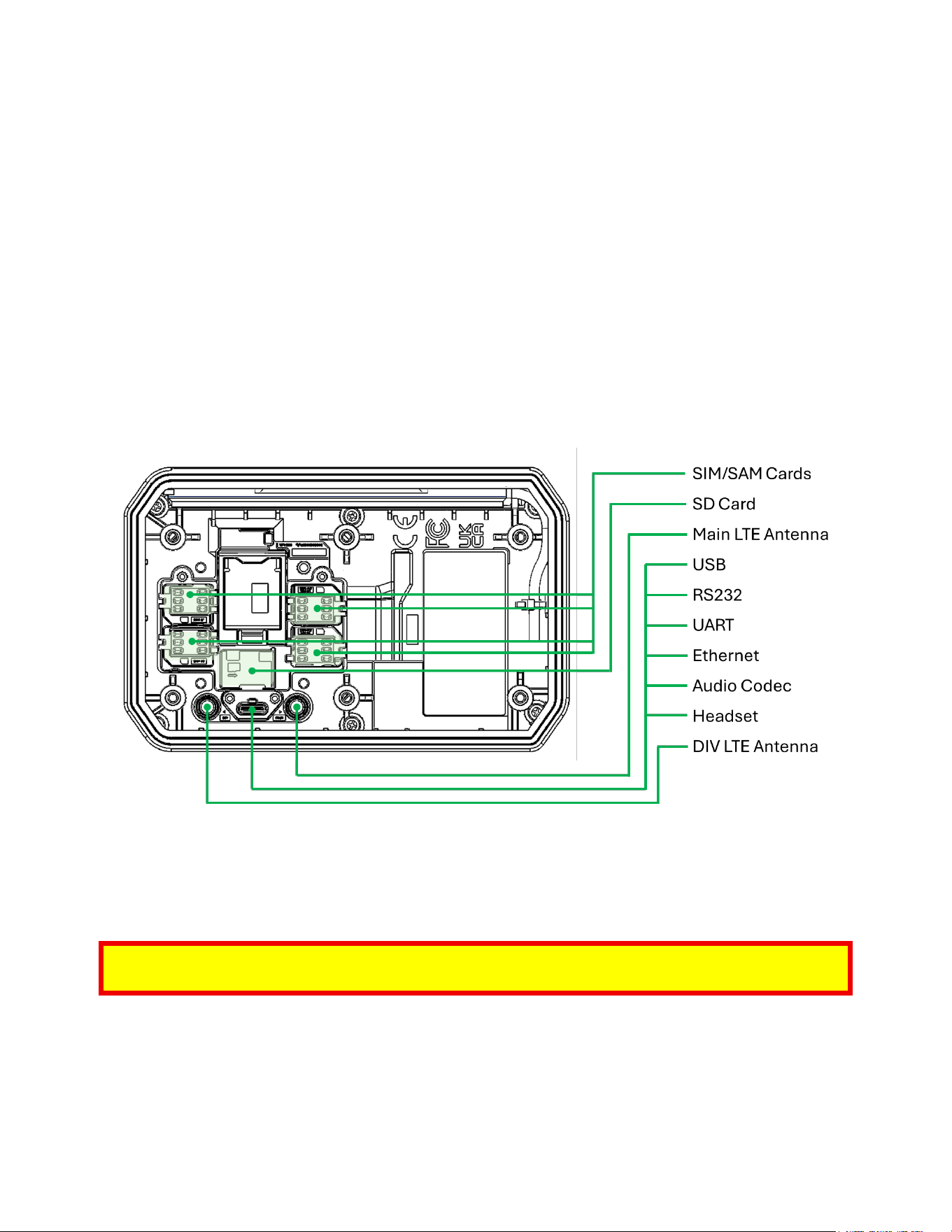
6.2. VP7225 Interface Connectors
The diagram below displays interface connectors for VP7225 readers.
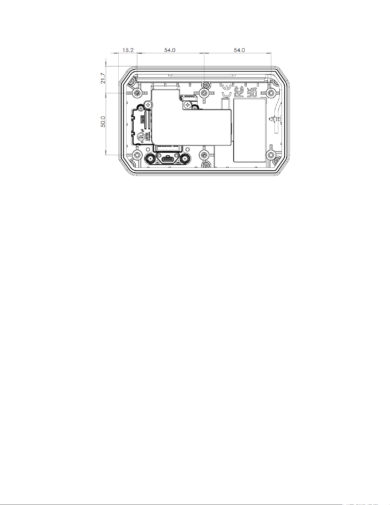
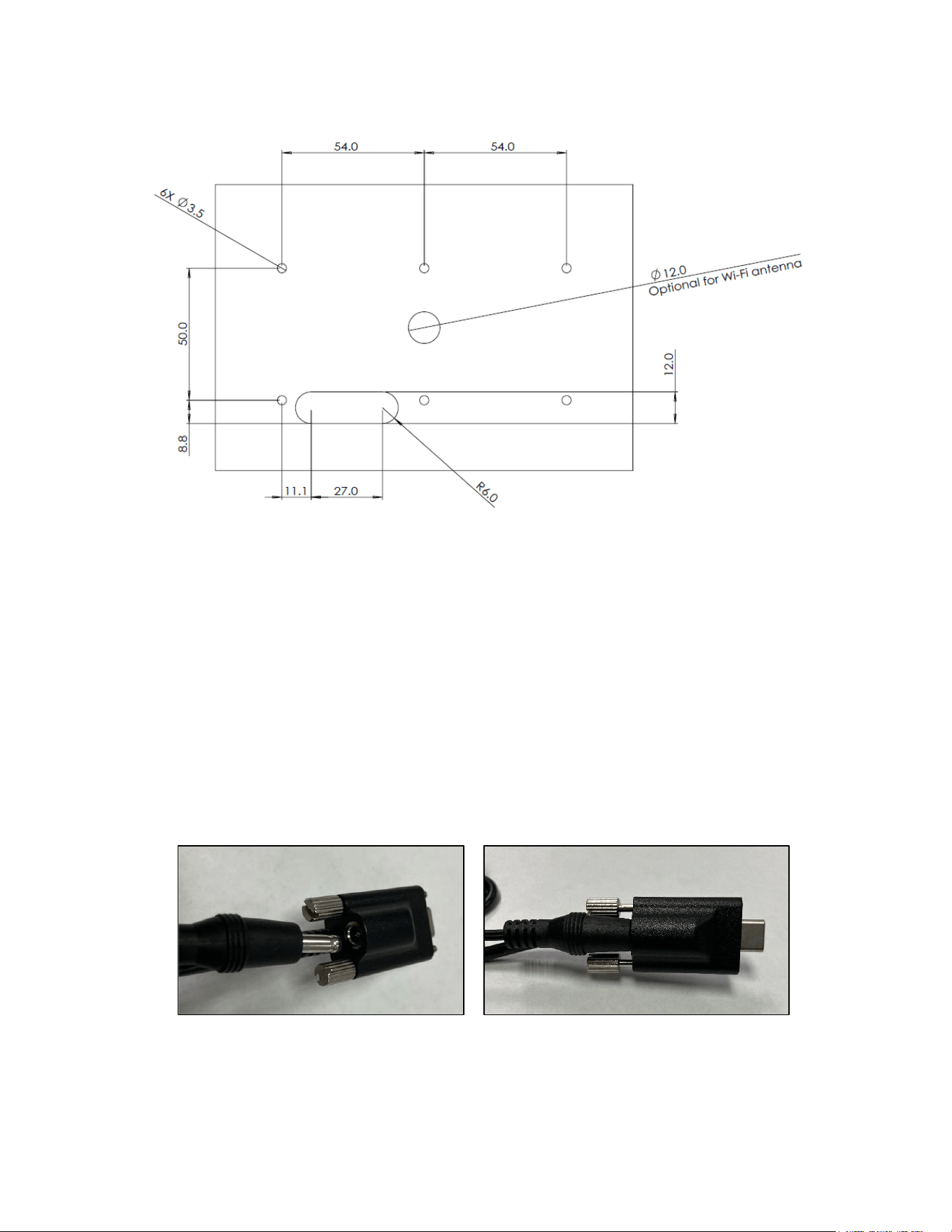
6.3. Mounting the VP7225
To optimize performance, install VP7225 readers away from or in front of any metal surfaces or
materials that have metallic content, which can interfere with the RF field. VP7225 readers perform
optimally when mounted away from metal surfaces.
Note: For safety reasons, make sure to mount the VP7225 at a height no greater than two meters from
the floor.
VP7225 User Manual
Page | 21
VP7225 User Manual
Page | 22
There are six M3 nuts in the bottom housing, which can be used to mount the unit to equipment.
6.4. VP7225 Hardware Connectors Guide
VP7225 readers have several options for connecting to hardware like host systems and LTE (wireless
internet) connections. This section provides details for each hardware type.
6.4.1. Connecting to Host Systems
VP7225 readers have multiple methods for connecting to host systems. Note that the cables below also
require a power adapter (P/N AC0005R-28) to power the VP7225.
• RS-232 (P/N to 80185224-001)
• USB-A to USB-C (P/N 80186214-001)
• Ethernet cable (P/N 80186228-001)
When connecting the VP7225 to a host system:
1. Insert the power adapter into the USB-C male end of the VP7225 connector cable; for safety,
make sure the power adapter is not yet plugged into an outlet.

VP7225 User Manual
Page | 23
2. Insert the USB-C male connector into the VP7225 reader.
a. Make sure to tighten the screws built into the connector to ensure the cable does not
become loose or dislodged.
3. Connect the cable to the host system.
4. Plug in the power adapter.
6.5. Communication via USB
The PID is 4700 (hex) and the VID is 0ACD (hex).
6.6. Connecting to LTE
Connecng a VP7225 to LTE requires mulple steps. Each secon below covers a dierent part of the
process in sequence.
6.6.1. Before You Begin
Make sure to have the following parts:
• VP7225
• SIM card
• One of the ID TECH connector cables described above
• Power adapter (P/N AC0005R-28)
• Antenna (P/N ANT009R)
You will also need:
• A Windows computer with the ID TECH Universal SDK Demo app installed (available at no
charge)
• A USB cable with a USB-C male connector
VP7225 User Manual
Page | 24
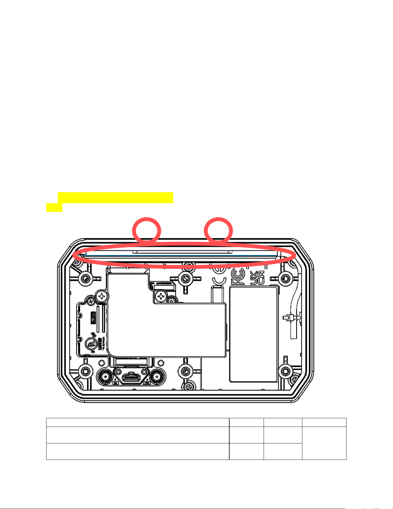
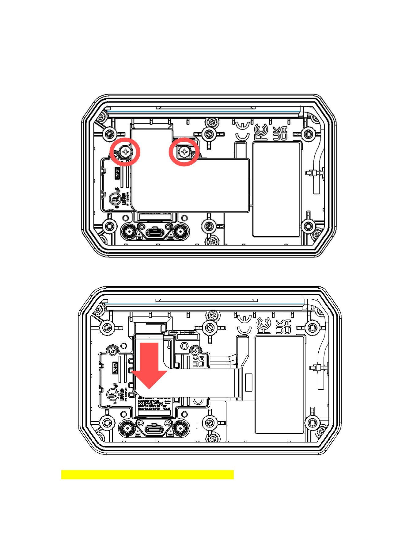
6.6.2. Accessing the SAM Slots
To access the reader's SAM slots:
1. Loosen the two screws below and remove the flexible printed circuit board (FPCB) cover.
2. Gently pull off the FPCB connector.
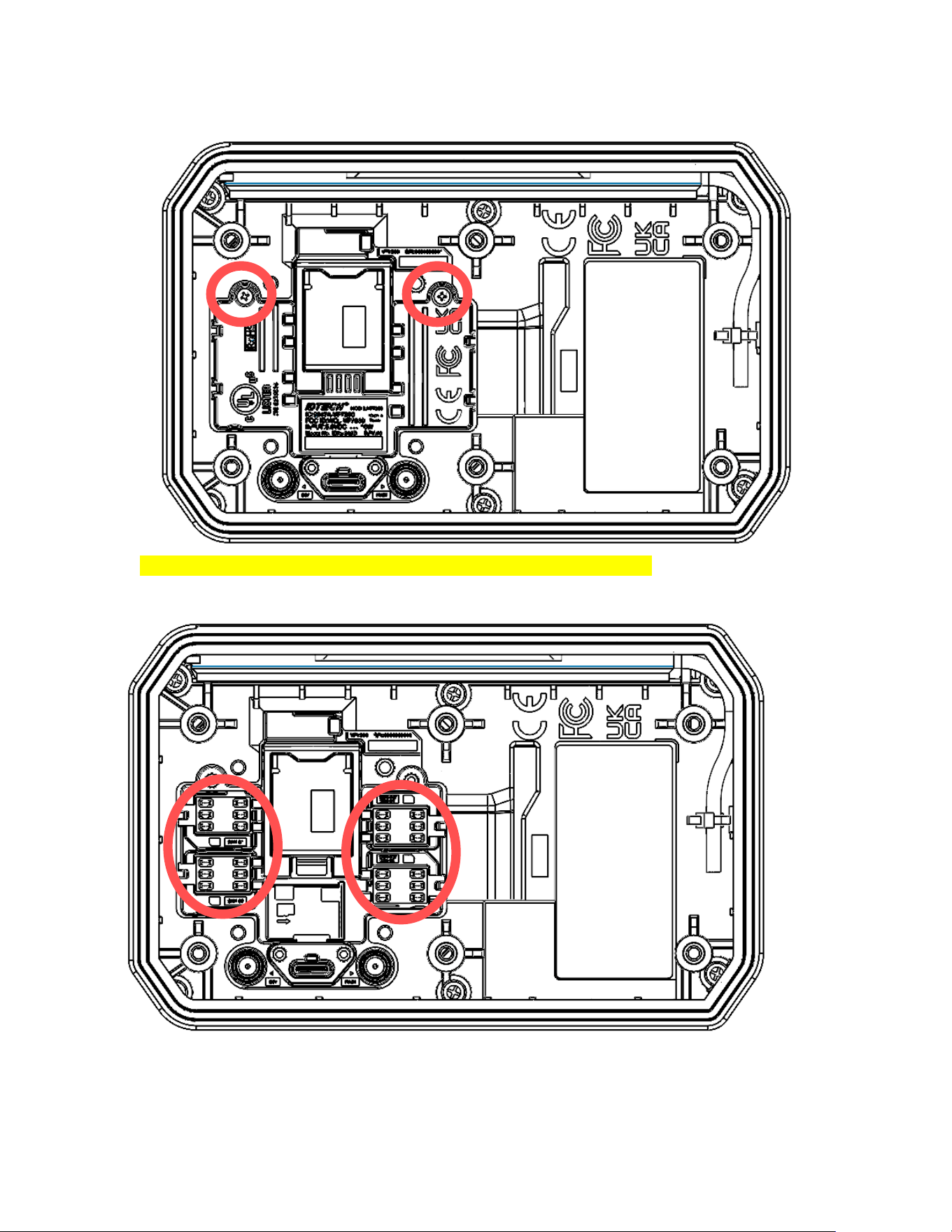
3. Loosen the two screws below and remove the cover.
VP7225 User Manual
Page | 25
4. When you see this screen, you can start installing the SIM/SAM cards.
VP7225 User Manual
Page | 26
6.6.3. Installing the SIM Card
To install the SIM card:
1. Aer removing the FPCB cover and removing the connector, locate the SIM slots.
2. Insert the SIM card into the desired slot. Make sure to note which slot you have used.
Note: For VP7225, the default SIM slot is Slot #1.
3. Close the SIM card panel on the VP7225.
6.6.4. Pairing the SIM Card
You must pair a SIM card before it can provide an LTE connecon. To pair the SIM card:

VP7225 User Manual
Page | 27
1. Open the Universal SDK Demo app on your Windows PC.
2. Connect your VP7225 to the computer and power on the reader.
3. Go to COMMANDS in the Universal SDK Demo app.
4. Use the Retrieve Cellular Switch Status (D3-02) command to check if cellular funconality is
enabled or disabled.
[TX]: 56 69 56 4F 74 65 63 68 32 00 D3 02 00 00 39 58
[RX]: 56 69 56 4F 74 65 63 68 32 00 D3 00 00 01 01 31 02
5. If cellular funconality is disabled, use the Cellular Switch Control (D3-01) command to enable
it. This change requires a device reboot.
[TX]: 56 69 56 4F 74 65 63 68 32 00 D3 01 00 01 01 47 B6
[RX]: 56 69 56 4F 74 65 63 68 32 00 D3 00 00 00 57 38
Note: If you switch the SIM card to another slot or insert a new SIM card, you must reboot the
device. LTE firmware does not support hot-swapping SIM cards.
6. To verify or change the SIM card slot in use, run the Retrieve Dual (U)SIM Card Slot Selecon
(D3-0C) command.
[TX]: 56 69 56 4F 74 65 63 68 32 00 D3 0C 00 00 22 59
[RX]: 56 69 56 4F 74 65 63 68 32 00 D3 00 00 01 01 31 02
7. If needed, send the Dual (U)SIM Card Slot Select (D3-0B) command to select the desired SIM
slot. The reader will reboot automacally aer switching the SIM slot.
[TX]: 56 69 56 4F 74 65 63 68 32 00 D3 0B 00 01 01 2F 1D
[RX]: 56 69 56 4F 74 65 63 68 32 00 D3 00 00 00 57 38
8. Use Detect (U)SIM Card in Slots (D3-0D) to check if the SIM card is funconing correctly. The
response data should be D3-00-01 if everything is working properly.
[TX]: 56 69 56 4F 74 65 63 68 32 00 D3 0D 00 01 01 08 84
[RX]: 56 69 56 4F 74 65 63 68 32 00 D3 00 00 01 01 31 02
9. Use the Retrieve Selected Network Operator Informaon (D3-0F) command to verify the
current network mode and selected operator. If the cellular network is not registered, use Auto
Register Cellular Operator to automacally register the device with an available operator.
Aer the expected operator informaon is returned, the reader should be able to communicate
via LTE.
[TX]: 56 69 56 4F 74 65 63 68 32 00 D3 0F 00 00 7B 09
[RX]: 56 69 56 4F 74 65 63 68 32 00 D3 00 00 1B 2B 43 4F 50 53 3A
20 30 2C 30 2C 22 4D 69 6E 74 22 2C 37 0D 0A 0D 0A 4F 4B 0D 0A 20
38 // +COPS: 0,0,"Mint",7
10. Use the Ping Remote Server (D3-06) command (in this case, “www.google.com”).
[TX]: 56 69 56 4F 74 65 63 68 32 00 D3 06 00 0E 77 77 77 2E 67 6F
6F 67 6C 65 2E 63 6F 6D 2C B6
[RX]: 56 69 56 4F 74 65 63 68 32 00 D3 00 00 A9 33 32 20 62 79 74
65 73 20 66 72 6F 6D 20 31 34 32 2E 32 35 30 2E 37 32 2E 31 33 32
3A 20 69 63 6D 70 5F 73 65 71 3D 30 20 74 69 6D 65 3D 32 39 31 20
VP7225 User Manual
Page | 28
6D 73 0A 33 32 20 62 79 74 65 73 20 66 72 6F 6D 20 31 34 32 2E 32
35 30 2E 37 32 2E 31 33 32 3A 20 69 63 6D 70 5F 73 65 71 3D 31 20
74 69 6D 65 3D 35 34 20 6D 73 0A 32 20 70 61 63 6B 65 74 73 20 74
72 61 6E 73 6D 69 74 74 65 64 2C 20 32 20 72 65 63 65 69 76 65 64
2C 20 30 25 20 70 61 63 6B 65 74 20 6C 6F 73 73 2C 20 74 69 6D 65
20 32 30 30 32 20 6D 73 0A A1 87
11. Enable the cellular auto-connect feature with the Cellular Auto Connect to Server (D3-03)
command.
[TX]: 56 69 56 4F 74 65 63 68 32 00 D3 03 00 01 01 AA DE
[RX]: 56 69 56 4F 74 65 63 68 32 00 D3 00 00 00 57 38
After completing SIM card installation and pairing, mount the VP7225 in the desired kiosk or other
location.
6.6.5. Enabling Cellular Functionality
VP7225 readers do not automatically detect SIM cards. After inserting the SIM card(s) and attaching the
antenna, use the Cellular Switch Control (D3-01) command to enable the SIM card.
Integrators having issues with LTE functionality should refer to LTE Diagnostic Troubleshooting.
Note: You must restart the device for the change to take effect.
6.6.5.1. Cellular Switch Control (D3-01)
The Cellular Switch Control command enables or disables cellular functionality. The reader saves the
specified configuration in flash.
Command Frame
Byte 0-9
Byte 10
Byte 11
Byte 12
Byte 13
Byte14
Byte 14+n
Byte 15+n
Header Tag &
Protocol
Version
Command
Sub-
Command
Data
Length
(MSB)
Data
Length
(LSB)
Data
CRC (LSB)
CRC (MSB)
ViVOtech2\0
D3h
01h
00h
01h
See send
data field
Variable
Variable
VP7225 User Manual
Page | 29
Command Data Field
Length
Description
1
00h: Disable cellular functionality.
01h: Enable cellular functionality.
Other: Reserved.
Response Frame
Byte 0-9
Byte 10
Byte 11
Byte 12
Byte 13
Byte 14
Byte 15
Header Tag &
Protocol Version
Command
Status Code
Data Length
(MSB)
Data Length
(LSB)
CRC (MSB)
CRC (LSB)
ViVOtech2\0
D2h
See status
code table
00h
00h
Variable
Variable
If necessary, use the Dual (U)SIM Card Slot Select (D3-0B) command to set the desired slot for Dual SIM
cards. See the NEO 2 Interface Developer's Guide for details.
6.6.6. Configure Cellular TCP/IP Context (D3-09)
Use the Configure Cellular TCP/IP Context command to set the reader's TCP/IP settings.
The Configure Cellular TCP/IP Context command is used for configuring the parameters of a TCP/IP
Context. The specified configuration is saved in flash.
Note the following:
1. If the username and password are empty, the authentication parameter should be 01h, 02h, or
03h.
2. Context ID currently only supports 01h.
3. Context Type currently only supports 01h.
4. If the response is an error, the LTE module cannot update the internal parameters completely as
requested, or some other error happened. In this case, the LTE module’s internal parameters
may be partially changed. Before the error returns, the firmware will try to revert the
parameters back to their original state.
5. LTE functionality takes effect after a device reboot.
Note: Network registration may take 10 to 40 seconds, depending on the network. Be sure to wait for
registration to complete before testing after the reader restarts.
Command Frame
Byte 0-9
Byte 10
Byte 11
Byte 12
Byte 13
Byte 14-
Byte 14+n-1
Byte 14+n
Byte 15+n
Header Tag
& Protocol
Version
Command
Sub-
Command
Data Length
(MSB)
Data Length
(LSB)
Data
CRC (LSB)
CRC (MSB)
ViVOtech2\
0
D3h
09h
Varies
Variable
See below
Variable
Variable
Command Data Format
VP7225 User Manual
Page | 30
Item
Description
Context ID
01h
02h
...
10h
Context Type
01h: IPv4
02h: IPv6
03h: IPv4v6
APN
Access Point Name.
ASCII, must end with 0x00. Maximum length is 63 bytes including null terminator.
Username
Username, provided by the ISP.
ASCII, must end with 0x00. Maximum length is 63 bytes including null terminator.
Password
Password of the target AP, provided by the ISP.
ASCII, must end with 0x00. Maximum length is 63 bytes including null terminator.
Authentication
00h: None
01h: PAP
02h: CHAP
03h: PAP or CHAP
Response Frame
Byte 0-9
Byte 10
Byte 11
Byte 12
Byte 13
Byte 14
Byte 15
Header Tag &
Protocol
Version
Command
Status Code
Data Length
(MSB)
Data Length
(LSB)
CRC (MSB)
CRC (LSB)
ViVOtech2\0
D3h
See status
code table
00h
00h
Variable
Variable
Example:
Set LTE APN configuration as:
Context ID: 1
Context Type: 1
APN: “IDTech”
Username: "”
Password: "”
Authentication: 0
Test the connection's ping with Ping Remote Server (D3-06) and verify the operator with Retrieve
Selected Network Operator Information (D3-0F).

VP7225 User Manual
Page | 31
6.7. SAM (Secure Access Module) Support
The VP7225 includes 4 SAM slots to enhance security for sensive operaons. It communicates with
SAM cards in pass-through mode.
6.7.1. Performance Tip for SAM Transactions
Please note that the best way to optimize performance is to minimize the number of APDU
exchanges, even if combining all operations into a single exchange is not feasible.
Reducing the frequency of APDU calls helps lower communication overhead and shortens overall
transaction time, especially critical in time-sensitive applications like fare collection or contactless
payments.
6.7.2. Installing SAM Cards
• SAM slots are located on the back of the device.
• Please insert or remove SAM cards only when the device is powered o to avoid hardware
damage.
6.7.3. Protocol and Communicaon
• Supported Protocols: ISO/IEC 7816 T=0 and T=1, depending on the card ATR.
• Maximum Baud Rate: Up to 125.1 Kbps.
• Clock Frequency: 4.002 MHz.
• The reader supports a wide range of TA1 conguraons for compability with various SAM cards.
* Note: For compatibility verification with custom or non-standard SAM cards, please contact IDTECH
technical support.
6.7.4. SAM Command Set
The VP7225 supports low-level ICC commands, enabling direct APDU communication with chip cards:
• The Pass-Through Mode Start/Stop (2C-01) command enables pass-through mode for direct
SAM card communication. You must issue this command before the reader can process any SAM
commands. This command also terminates pass-through mode.
• The Get ATR (2C-12) command activates the ICC and establishes a Layer 1 session to retrieve the
ATR.
• The Exchange APDU Data (2C-13) command exchanges APDU data with the SAM card.
• The Contact Transacon Power O (2C-18) command powers o the SAM card. When a
transaction is successful, the ICC slot or SAM needs to power off before the user removes their
card.
6.7.5. Example SAM Operaon Flow
1. Use the Pass-Through Mode Start/Stop (2C-01) command to enable SAM card access. You must
issue this command before sending any APDU commands.
[TX]: 56 69 56 4F 74 65 63 68 32 00 2C 01 00 01 01 19 1D
[RX]: 56 69 56 4F 74 65 63 68 32 00 2C 00 00 00 1C 9B
2. Use the Get ATR (2C-12) command to acvate the selected SAM slot and retrieve its ATR
(Answer to Reset).

VP7225 User Manual
Page | 32
[TX]:56 69 56 4F 74 65 63 68 32 00 2C 12 00 01 21 00 B9
[RX]:56 69 56 4F 74 65 63 68 32 00 2C 00 00 12 3B F8 96 00 00 81
31 FE 45 4A 43 4F 50 76 32 34 31 32 FD E1
3. Use the Exchange APDU Data (2C-13) command to send ISO/IEC 7816-compliant APDU
commands to the SAM card and receive the response.
[TX]:56 69 56 4F 74 65 63 68 32 00 2C 13 00 15 21 00 A4 04 00 0E
31 50 41 59 2E 53 59 53 2E 44 44 46 30 31 00 AD E5
[RX]:56 69 56 4F 74 65 63 68 32 00 2C 00 00 28 6F 24 84 0E 31 50
41 59 2E 53 59 53 2E 44 44 46 30 31 A5 12 88 01 01 5F 2D 08 65 73
65 6E 66 72 64 65 9F 11 01 01 90 00 5F 72
4. Use the Contact Transacon Power O (2C-18) command to shut down the SAM card and
terminate the ICC session.
[TX]:56 69 56 4F 74 65 63 68 32 00 2C 18 00 01 21 AB D1
[RX]:56 69 56 4F 74 65 63 68 32 00 2C 00 00 00 1C 9B
5. Use the Pass-Through Mode Start/Stop (2C-01) command again to reinialize the SAM interface
(for example, when switching to another slot or starng a new session).
[TX]:56 69 56 4F 74 65 63 68 32 00 2C 01 00 01 00 38 0D
[RX]:56 69 56 4F 74 65 63 68 32 00 2C 00 00 00 1C 9B
Note: Step 5 is optional and used to re-enter pass-through mode (for example, for switching to another
SAM slot).
Detailed descriptions of these commands can be found in the NEO 2 Interface Developer's Guide.
It is the responsibility of the integrator to develop their own applicaon to interface with the device
using IDG commands.

VP7225 User Manual
Page | 33
6.8. Connecting to the Data Port
The VP7225 has three data connection options: USB, RS-232, and Ethernet through the USB-C
connector.
USB-C Connector
PIN#
Function
PIN#
Function
A1
GND
B12
GND
A2
RS232_TX→
B11
RS232_RX←
A3
RS232_RTS→
B10
RS232_CTS←
A4
VBUS
B9
VBUS
A5
CC1
B8
LINEOUT_R
A6
USB_DP
B7
UART_TX→(3.3V IO)
A7
USB_DN
B6
UART_RX←(3.3V IO)
A8
LINEOUT_L
B5
MIC_DET
A9
VBUS
B4
VBUS
A10
ETHERNET_RXN
B3
ETHERNET_TXN
A11
ETHERNET_RXP
B2
ETHERNET_TXP
A12
GND
B1
GND
6.9. Installation Checklist
When installing VP7225 units, be sure to verify the following items.
6.9.1. Visual Inspection
Before installing a VP7225:
• Visually inspect the reader for any modifications on the plastic housing.
• Check the security labels over the screws to verify the reader has not been tampered with.
• Power up the reader and check for any flashing LEDs and beeps that indicate tampering. Refer
to Tamper and Failed Self-Check indicators for specific information.
6.9.2. Installation Procedures
After visually inspecting the VP7225, follow these guidelines when integrating the reader to your
system:
• Insert any Security Access Modules into the SAM sockets.
• For additional memory expansion, insert any microSD card into the uSD socket.
• If your unit supports LTE radio, insert your network SIM into the SIM sockets.
• Close the cover and install the unit in its housing using four screws. Note: Do not overtighten
the screws.
• If the display module is supported, insert the display module flex into the optional LCD
connector.
• Insert the communication/power cable into the USB-C connector and tighten the locking screws
(if provided).
• Power on the whole system and check the unit’s operations.
6.9.3. Recommendations
Additionally, follow these recommendations after installation:
• Periodically inspect the system for any tampering and insertion of electronic bugs.
• Look for the latest updates on the manual or firmware on the ID TECH website.
VP7225 User Manual
Page | 34
• See the Installation Points, and Firmware Upgrade sections below for additional information
about verifying device functionality and performing maintenance.
6.10. Using the VP7225 to Make a Purchase
The section below provides instructions for making purchases with the VP7225.
6.10.1. Presenting Cards or NFC Phones
The VP7225 allows for credit/debit card purchases using Contactless (NFC) technology.
Present the card/phone in close proximity to the front portion of the antenna module. Present the
card/phone so that maximum surface area is parallel to the antenna module as shown below.
The antenna should beep, and the four green LEDs should illuminate in sequence, then all will illuminate
together, briefly (750 msec), to indicate a successful test.
This tests the VP7225’s ability to read the Contactless test card. If unsuccessful, there will be no reaction
from the reader. If you use a test card and the VP7225 antenna is attached to the VP7225 Controller, a
dummy transaction can be tested. The transaction will not be authorized and will come back with a
response but will at least test for end-to-end connectivity.

VP7225 User Manual
Page | 35
6.10.2. Making a Purchase
After the transaction has been entered on the kiosk control panel, the customer should present his or
her card/fob/phone in close proximity with the device so that maximum surface area is parallel to the
antenna.
• A single beep and all four LEDs briefly flashing indicates the card/fob/phone has been read
correctly.
6.11. Installation Points
• The VP7225 is NOT designed to be mounted on a metal surface and in close proximity to any
internal motors and electrical devices that may be operating inside the kiosk. However, the
VP7225 is susceptible to RF and electromagnetic interference. It is important that the unit not
be mounted near (within 3 or 4 feet) large electric motors, computer UPS systems, microwave
transmitters (Wi-Fi routers), anti-theft devices, radio transmitters, communications equipment
and so on.
• Close proximity of metal to the RF-emitting end of the antenna can greatly reduce the range of
the antenna. See the precautions described in Flush Mounting the VP7225 Antenna.
• Make sure to install the SAM/SIM card cover before checking SAM/SIM cards functions.
• Tie all cables neatly with nylon cable-ties and route them so that they are inaccessible and
invisible to customers. Label the cable ends, host, ID TECH and power, to simplify connection
testing or component replacement.
• Test the VP7225 installation using a test card to perform an end-to-end transaction (the same as
an actual purchase on the Kiosk). The kiosk display panel (if it exists) should display "Requesting
Authorization." Even if the transaction is declined (as it should be with a test card), it will prove
connectivity all the way through the system. If possible, the store manager or some other
responsible party should test each VP7225 on a regular basis (perhaps at the start of each day or
at least once per week) with a test card to ensure continued operation and functionality. If the
kiosk is rebooted on a regular basis (such as every night), it is important to test the contactless
reader as soon as possible afterwards to ensure continued communication to the kiosk host.
VP7225 User Manual
Page | 36
7. VP7225 Configuration Settings
VP7225 integrators can configure readers via IDG commands. Refer to the NEO 2 Interface Developer's
Guide for a complete list of commands (available from your ID TECH representative).
7.1. Configuring Ethernet Settings
The section below describes configuring VP7225 ethernet settings.
7.1.1. Configuring Ethernet Settings with Low-Level Commands
To configure ethernet settings via low-level commands, send the following commands in sequence:
1. Set Network Configuration (D1-13)
2. Get Network Configuration (D1-15)
3. Set Ethernet SSL Request Configuration (D2-01)
4. Get Ethernet SSL Request Configuration (D2-02)
7.1.1.1. Set Network Configuration (D1-13)
The Set Network Configuration command sets the static network DHCP for the reader. If set static, the
network configuration is saved. If set DHCP, reader will function as a DHCP client to get the network
configuration from the host device.
Command Frame
Byte 0-9
Byte 10
Byte 11
Byte 12
Byte 13
Byte 14-
Byte 13+n
Byte 19
Byte 20
Header Tag &
Protocol
Command
Sub
Command
Length
MSB
Length
LSB
Data
CRC
(LSB)
CRC
(MSB)
ViVOtech2/0
D1h
13h
00h
variable
See blow
Varies
Varies
Length
Description
2
Determine to set static or DHCP. Zero-terminated ASCII value.
30h: Set DHCP.
31h: Set static IP network configuration.
Variable
IP address, zero-terminated ASCII. Maximum length is 16 bytes including null terminator.
Variable
Net mask, zero-terminated ASCII. Maximum length is 16 bytes including null terminator.
Variable
Gateway, zero-terminated ASCII. Maximum length is 16 bytes including null terminator.
Variable
DNS, zero-terminated ASCII. Maximum length is 16 bytes including null terminator.
VP7225 User Manual
Page | 37
Response Frame
Byte 0-9
Byte 10
Byte 11
Byte 12
Byte 13
Byte 14
Byte 15
Header Tag &
Protocol
Command
Status
Length
MSB
Length
LSB
CRC
(MSB)
CRC
(LSB)
ViVOtech2/0
D1h
See status
code table
00h
00h
Varies
Varies
Example:
Set ethernet configuration as:
IP address:
192.168.6.99
Net mask:
255.255.255.0
Gateway:
192.168.6.1
DNS:
192.168.6.17
TX: 56 69 56 4F 74 65 63 68 32 00 D1 13 00 36 31 00 31 39 32 2E 31 36 38
2E 36 2E 39 39 00 32 35 35 2E 32 35 35 2E 32 35 35 2E 30 00 31 39 32
2E 31 36 38 2E 36 2E 31 00 31 39 32 2E 31 36 38 2E 36 2E 31 37 00 04
8B
RX: 56 69 56 4F 74 65 63 68 32 00 D1 00 00 00 50 BA
7.1.1.2. Get Network Configuration (D1-15)
The Get Network Configuration command retrieves all network configurations for the VP7225.
Command Frame
Byte 0-9
Byte 10
Byte 11
Byte 12
Byte 13
Byte 14
Byte 15
Byte 16
Header Tag &
Protocol
Command
Sub
Command
Length
MSB
Length
LSB
Data
CRC
(LSB)
CRC
(MSB)
ViVOtech2/0
D1h
15h
00h
01h
00
Varies
Varies
Response Frame
Byte 0-9
Byte 10
Byte 11
Byte 12
Byte 13
Byte 14-
Byte 19
Byte 14+n
Byte 14+n+1
Header Tag &
Protocol
Command
Status
Length
MSB
Length
LSB
Data
CRC
(MSB)
CRC
(LSB)
ViVOtech2/0
D1h
See status
code table
00h
variable
Data
(See D1-13
command)
Varies
Varies
VP7225 User Manual
Page | 38
7.1.1.3. Set Ethernet SSL Request Configuration (D2-01, PCI only)
The Set Ethernet SSL Request Configuration command sets the reader’s SSL-request-to-SSL-client
configuration.
This command saves the server IP and port number in the client’s flash memory. When the reader
powers on it connects automatically to the remote server.
Command Frame
Byte 0-9
Byte 10
Byte 11
Byte 12
Byte 13
Bye14-
13+n
Byte 14+n
Byte 15+n
Header Tag &
Protocol
Version
Command
Sub-
Command
Data
Length
(MSB)
Data
Length
(LSB)
Data
CRC
(LSB)
CRC (MSB)
ViVOpayV3\0
D2h
01h
variable
variable
See send
data field
Command Data Field
Length
Description
Variable
Server IP address, zero terminated ASCII. Maximum length is 16 bytes including null terminator.
2
Port number, HEX value, Big Endian.
1
00
Response Frame
Byte 0-9
Byte 10
Byte 11
Byte 12
Byte 13
Byte 14
Byte 15
Header Tag &
Protocol Version
Command
Status Code
Data
Length
(MSB)
Data
Length
(LSB)
CRC (MSB)
CRC (LSB)
ViVOtech2\0
D2h
See status
code table
00h
00h
Example: Server IP 192.168.6.126, port: 1443
OUT: 5669564f746563683200d20100113139322e3136382e362e3132360005a3004592
IN: 5669564f746563683200d2000000218c
VP7225 User Manual
Page | 39
7.1.1.4. Get Ethernet SSL Request Configuration (D2-02, PCI only)
The Get Ethernet SSL Request Configuration command retrieves the server’s IP address and port
number from flash memory.
Command Frame
Byte 0-9
Byte 10
Byte 11
Byte 12
Byte 13
Bye14-
13+n
Byte 14+n
Byte 15+n
Header Tag &
Protocol
Version
Command
Sub-
Command
Data
Length
(MSB)
Data
Length
(LSB)
Data
CRC
(LSB)
CRC (MSB)
ViVOpayV3\0
D2h
02h
00
01
00
Response Frame
Byte 0-9
Byte 10
Byte 11
Byte 12
Byte 13
Byte 14-
Byte 19
Byte 14+n
Byte 14+n+1
Header Tag &
Protocol
Command
Status
Length
MSB
Length
LSB
Data
CRC
(MSB)
CRC
(LSB)
ViVOtech2/0
D2h
See status
code table
00h
variable
Data
(See D2-01
command)
Varies
Varies
Example: Server IP 192.168.6.126, port: 1443
OUT: 56 69 56 4F 74 65 63 68 32 00 D2 02 00 01 00 66 1A
IN: 56 69 56 4F 74 65 63 68 32 00 D2 00 00 11 31 39 32 2E 31 36 38 2E 36
2E 31 32 36 00 05 A3 00 A7 F6
VP7225 User Manual
Page | 40
Configuring BLE Settings
The section below describes configuring VP7225 BLE settings.
7.1.2. Configuring BLE with Low-Level Commands
To configure BLE settings via low-level commands, send the following commands in sequence:
1. Set Bluetooth Parameters (Name) (77-81)
2. Get Bluetooth Name (77-82)
3. Get Bluetooth Local Information (77-83)
7.1.2.1. Set Bluetooth Parameters (Name) (77-81)
The Set Bluetooth Parameters command sets a Bluetooth name.
Command Frame
Byte 0-9
Byte 10
Byte 11
Byte 12
Byte 13
Byte 14
Byte 14+n
Byte 15+n
Header Tag &
Protocol
Version
Command
Sub-
Command
Data
Length
(MSB)
Data
Length
(LSB)
Data
CRC (LSB)
CRC (MSB)
ViVOtech2\0
77h
81h
var
var
Command Data Field
Data Field
Length (bytes)
Description
Name
Var to 26
ASCII, must end with 0x00
Response Frame
Byte 0-9
Byte 10
Byte 11
Byte 12
Byte 13
Byte 14
Byte 15
Header Tag &
Protocol Version
Command
Status Code
Data Length
(MSB)
Data Length
(LSB)
CRC (MSB)
CRC (LSB)
ViVOtech2\0
77h
See Status
Code Table
00h
00h
7.1.2.2. Get Bluetooth Name (77-82)
The Get Bluetooth Name command retrieves a Bluetooth name.
Command Frame
Byte 0-9
Byte 10
Byte 11
Byte 12
Byte 13
Byte 14
Byte 14+n
Byte 15+n
Header Tag &
Protocol Version
Command
Sub-
Command
Data Length
(MSB)
Data Length
(LSB)
Data
CRC (LSB)
CRC (MSB)
ViVOtech2\0
77h
82h
00h
00h
null
VP7225 User Manual
Page | 41
Response Frame
Byte 0-9
Byte 10
Byte 11
Byte 12
Byte 13
Byte 14 …
Byte 14+n-1
Byte 14+n
Byte 15+n
Header Tag &
Protocol
Version
Command
Status Code
Data
Length
(MSB)
Data
Length
(LSB)
Data
CRC (MSB)
CRC (LSB)
ViVOtech2\0
77h
See status
code table
var
ASCII
(<26 bytes)
The Bluetooth name of the response data must be less than 26 bytes.
7.1.2.3. Get Bluetooth Local Information (77-83)
The Get Bluetooth Local Information command retrieves Bluetooth local information for the module
version and Bluetooth address.
Command Frame
Byte 0-9
Byte 10
Byte 11
Byte 12
Byte 13
Byte 14
Byte 14+n
Byte 15+n
Header Tag &
Protocol
Version
Command
Sub-
Command
Data
Length
(MSB)
Data
Length
(LSB)
Data
CRC (LSB)
CRC (MSB)
ViVOtech2\0
77h
83h
var
Response Frame
Byte 0-9
Byte 10
Byte 11
Byte 12
Byte 13
Byte 14 …
Byte 14+n-1
Byte 14+n
Byte 15+n
Header Tag
& Protocol
Version
Command
Status Code
Data Length
(MSB)
Data Length
(LSB)
Data
CRC (MSB)
CRC (LSB)
ViVOtech2\
0
77h
See status
code table
00h
0Dh
See below
data table
Data Table: Get Bluetooth Local information
Data Item
Length (bytes)
Description
Event
2
Reserved
Version
4
Firmware version (BCD)
Address
6
ASCII code MAC Address (LSB)
Identify
1
0x02: CYW43455
VP7225 User Manual
Page | 42
7.2. Configuring LTE Settings
The section below describes configuring VP7225 LTE settings.
7.2.1. Configuring LTE Settings with Low-Level Commands
To configure LTE settings via low-level commands, send the following commands in sequence:
1. Cellular Switch Control (D3-01)
2. Retrieve Cellular Switch Status (D3-02)
3. Cellular Auto Connect Control (D3-03)
4. Retrieve Cellular Auto Connect Status (D3-04)
5. Configure Cellular Remote Server IP Address and Port Number (D3-07)
6. Configure Cellular Remote Server IP Address and Port Number (D3-08)
7. Configure Cellular TCP/IP Context (D3-09)
8. Retrieve Cellular TCP/IP Context (D3-0A)
7.2.1.1. Cellular Switch Control (D3-01)
The Cellular Switch Control command enables or disables cellular functionality. The reader saves the
specified configuration in flash.
Note: This function takes effect after a device reboot.
Command Frame
Byte 0-9
Byte 10
Byte 11
Byte 12
Byte 13
Byte14
Byte 14+n
Byte 15+n
Header Tag &
Protocol
Version
Command
Sub-
Command
Data
Length
(MSB)
Data
Length
(LSB)
Data
CRC (LSB)
CRC (MSB)
ViVOtech2\0
D3h
01h
00h
01h
See send
data field
Variable
Variable
Command Data Field
Length
Description
1
00h: Disable cellular functionality.
01h: Enable cellular functionality.
Other: Reserved.
Response Frame
Byte 0-9
Byte 10
Byte 11
Byte 12
Byte 13
Byte 14
Byte 15
Header Tag &
Protocol Version
Command
Status Code
Data
Length
(MSB)
Data
Length
(LSB)
CRC (MSB)
CRC (LSB)
ViVOtech2\0
D3h
See status
code table
00h
00h
Variable
Variable
VP7225 User Manual
Page | 43
7.2.1.2. Retrieve Cellular Switch Status (D3-02)
The Retrieve Cellular Switch Status command retrieves the cellular functionality enable or disable
status.
Command Frame
Byte 0-9
Byte 10
Byte 11
Byte 12
Byte 13
Byte 14+n
Byte 15+n
Header Tag &
Protocol
Version
Command
Sub-
Command
Data
Length
(MSB)
Data
Length
(LSB)
CRC (LSB)
CRC (MSB)
ViVOpayV3\0
D3h
02h
00
00
Variable
Variable
Response Frame
Byte 0-9
Byte 10
Byte 11
Byte 12
Byte 13
Byte 14
Byte 14+n
Byte 14+n+1
Header Tag &
Protocol
Command
Status
Length
MSB
Length
LSB
Data
CRC
(MSB)
CRC
(LSB)
ViVOtech2/0
D3h
See status
code table
00h
01h
Data
Variable
Variable
Response Data Field
Length
Description
1
00h: Cellular functionality is disabled.
01h: Cellular functionality is enabled.
Other: Reserved.
7.2.1.3. Cellular Auto Connect Control (D3-03)
The Cellular Auto Connect Control command enables or disables the reader’s auto connect feature. The
reader connects to the remote server automatically when it starts up. The reader saves the specified
configuration in flash.
Note: This function takes effect after a device reboot.
Command Frame
Byte 0-9
Byte 10
Byte 11
Byte 12
Byte 13
Bye14
Byte 14+n
Byte 15+n
Header Tag &
Protocol
Version
Command
Sub-
Command
Data
Length
(MSB)
Data
Length
(LSB)
Data
CRC (LSB)
CRC (MSB)
ViVOtech2\0
D3h
03h
00h
01h
See Command
Data Field
Variable
Variable
VP7225 User Manual
Page | 44
Command Data Field
Length
Description
1
00h: Cellular functionality will not connect to the remote server automatically.
01h: Cellular functionality will connect to the remote server automatically.
Other: Reserved.
Response Frame
Byte 0-9
Byte 10
Byte 11
Byte 12
Byte 13
Byte 14
Byte 15
Header Tag &
Protocol Version
Command
Status Code
Data
Length
(MSB)
Data Length
(LSB)
CRC (MSB)
CRC (LSB)
ViVOtech2\0
D3h
See status code
table
00h
00h
Variable
Variable
7.2.1.4. Retrieve Cellular Auto Connect Status (D3-04)
The Retrieve Cellular Auto Connect Status command retrieves the cellular functionality auto connect
feature status.
Command Frame
Byte 0-9
Byte 10
Byte 11
Byte 12
Byte 13
Byte 14+n
Byte 15+n
Header Tag &
Protocol
Version
Command
Sub-
Command
Data
Length
(MSB)
Data
Length
(LSB)
CRC (LSB)
CRC (MSB)
ViVOtech2\0
D3h
04h
00
00
Response Frame
Byte 0-9
Byte 10
Byte 11
Byte 12
Byte 13
Byte 14
Byte 14+n
Byte 14+n+1
Header Tag &
Protocol
Command
Status
Length
MSB
Length
LSB
Data
CRC
(MSB)
CRC
(LSB)
ViVOtech2/0
D3h
See status
code table
00h
01h
Data
Variable
Variable
Response Data Field
Length
Description
1
00h: Cellular functionality will not connect to the remote server automatically.
01h: Cellular functionality will connect to the remote server automatically.
Other: Reserved.
VP7225 User Manual
Page | 45
7.2.1.5. Configure Cellular Remote Server IP Address and Port Number (D3-07)
The Configure Cellular Remote Server IP Address and Port Number command configures the remote
server IP address and port number. The reader saves the specified configuration in flash.
Command Frame
Byte 0-9
Byte 10
Byte 11
Byte 12
Byte 13
Byte 14 …
Byte 14+n-1
Byte 14+n
Byte 15+n
Header Tag &
Protocol
Version
Command
Sub-
Command
Data
Length
(MSB)
Data
Length
(LSB)
Data
CRC (LSB)
CRC (MSB)
ViVOtech2\0
D3h
07h
Variable
Variable
See Command
Data Field
Variable
Variable
Command Data Field
Length
Description
Variable
Server IP address, zero terminated ASCII. Maximum length is 16 bytes including null terminator
2
Port number, HEX value, Little Endian
Response Frame
Byte 0-9
Byte 10
Byte 11
Byte 12
Byte 13
Byte 14
Byte 15
Header Tag &
Protocol Version
Command
Status Code
Data
Length
(MSB)
Data
Length
(LSB)
CRC (MSB)
CRC (LSB)
ViVOtech2\0
D3h
See status
code table
00h
00h
Variable
Variable
Example:
Server IP: 180.169.129.58, Port: 1555(0x1306)
TX: 56 69 56 4F 74 65 63 68 32 00 D3 07 00 11 31 38 30 2E 31 36 39 2E 31
32 39 2E 35 38 00 13 06 0C 0A
RX: 56 69 56 4F 74 65 63 68 32 00 D3 00 00 00 57 38
VP7225 User Manual
Page | 46
7.2.1.6. Retrieve Cellular Remote Server IP Address and Port Number (D3-08)
The Retrieve Cellular Remote Server IP Address and Port Number command retrieves the remote
server IP address and port number.
Command Frame
Byte 0-9
Byte 10
Byte 11
Byte 12
Byte 13
Byte 14
Byte 15
Header Tag &
Protocol
Version
Command
Sub-Command
Data Length
(MSB)
Data Length
(LSB)
CRC (LSB)
CRC (MSB)
ViVOtech2\0
D3h
08h
00
00
Variable
Variable
Response Frame
Byte 0-9
Byte 10
Byte 11
Byte 12
Byte 13
Byte 14-
Byte 14+n-1
Byte 14+n
Byte 14+n+1
Header Tag &
Protocol
Command
Status
Length
MSB
Length
LSB
Data
CRC (MSB)
CRC (LSB)
ViVOtech2/0
D3h
See status
code table
00h
Variable
See
Response
Data Field
Variable
Variable
Response Data Field
Length
Description
Variable
Server IP address, zero terminated ASCII. Maximum length is 16 bytes including null terminator
2
Port number, HEX value, Little Endian
Example:
Server IP: 180.169.129.58, Port: 1555(0x1306)
TX: 56 69 56 4F 74 65 63 68 32 00 D3 08 00 00 99 FE
RX: 56 69 56 4F 74 65 63 68 32 00 D3 00 00 12 31 38 30 2E 31 36 39 2E 31
32 39 2E 35 38 00 13 06 00 D6 CA
VP7225 User Manual
Page | 47
7.2.1.7. Configure Cellular TCP/IP Context (D3-09)
The Configure Cellular TCP/IP Context command is used for configuring the parameters of a TCP/IP
Context. The specified configuration is saved in flash.
Note:
1. If username and password are not empty, the authentication parameter should not be 0.
2. Context ID currently only supports 01h.
3. Context Type currently only supports 01h.
4. If the response is an error, it means the LTE module cannot update the internal parameters
completely as requested, or some other error happened. In this case, the LTE module’s internal
parameters may be partially changed. Before the error returns, the firmware will try to revert the
parameters back to their original state.
5. This function takes effect after a device reboot.
Command Frame
Byte 0-9
Byte 10
Byte 11
Byte 12
Byte 13
Byte 14-
Byte 14+n-1
Byte 14+n
Byte 15+n
Header Tag &
Protocol
Version
Command
Sub-
Command
Data Length
(MSB)
Data Length
(LSB)
Data
CRC (LSB)
CRC (MSB)
ViVOtech2\0
D3h
09h
Varies
Variable
See below
Variable
Variable
Command Data Format
Item
Description
Context ID
01h
02h
...
10h
Context Type
01h: IPv4
02h: IPv6
03h: IPv4v6
APN
Access Point Name.
ASCII, must end with 0x00. The maximum length is 63 bytes including null terminator.
Username
Username, provided by the ISP.
ASCII, must end with 0x00. The maximum length is 63 bytes including null terminator.
Password
Password of the target AP, provided by the ISP.
ASCII, must end with 0x00. The maximum length is 63 bytes including null terminator.
Authentication
00h: None
01h: PAP
02h: CHAP
03h: PAP or CHAP
VP7225 User Manual
Page | 48
Response Frame
Byte 0-9
Byte 10
Byte 11
Byte 12
Byte 13
Byte 14
Byte 15
Header Tag &
Protocol
Version
Command
Status Code
Data Length
(MSB)
Data Length
(LSB)
CRC (MSB)
CRC (LSB)
ViVOtech2\0
D3h
See status
code table
00h
00h
Variable
Variable
Example:
Set LTE APN configuration as:
Context ID: 1
Context Type: 1
APN: “IDTech”
Username: "”
Password: "”
Authentication: 0
7.2.1.8. Retrieve Cellular TCP/IP Context (D3-0A)
The Retrieve Cellular TCP/IP Context command retrieves the parameters of a TCP/IP context.
Command Frame
Byte 0-9
Byte 10
Byte 11
Byte 12
Byte 13
Byte 14
Byte 15
Header Tag &
Protocol Version
Command
Sub-
Command
Data Length
(MSB)
Data Length
(LSB)
CRC (LSB)
CRC (MSB)
ViVOtech2\0
D3h
0Ah
00h
00h
Variable
Variable
Response Frame
Byte 0-9
Byte 10
Byte 11
Byte 12
Byte 13
Byte14…
14+n-1
Byte 14+n
Byte 15+n
Header Tag &
Protocol
Version
Command
Status Code
Data Length
(MSB)
Data Length
(LSB)
Data
CRC (MSB)
CRC (LSB)
ViVOtech2\0
D3h
See status
code table
Variable
Variable
Refer to D3-
09
Command
Data Format
Variable
Variable
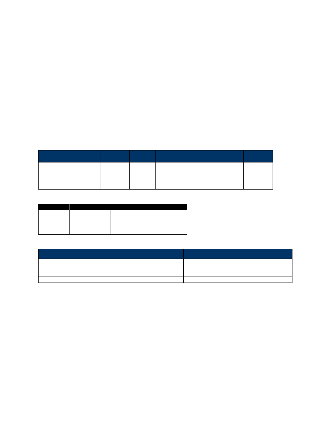
VP7225 User Manual
Page | 49
7.3. Configuring System Settings
The section below describes configuring VP7225 backlight and audio volume settings.
7.3.1. Configuring System Settings with Low-Level Commands
To configure system settings via low-level commands, send the following commands to the reader (they
can be sent independently of each other):
• Set Backlight (83-2F)
• Set/Get Audio Volume (61-32)
• Get System Info (09-15)
7.3.1.1. Set Backlight (83-2F)
This command sets the VP7225’s backlight level. If the level is set to >100%, the command will be
rejected; if the level is set to <10%, backlight level will be set to 10%.
Command Frames
Byte 0-9
Byte 10
Byte 11
Byte 12
Byte 13
Byte 14-
Byte17
Byte 18
Byte 19
Header Tag &
Protocol
Version
Command
Sub-
Command
Data
Length
(MSB)
Data Length
(LSB)
Data
CRC (LSB)
CRC (MSB)
ViVOpayV2\0
83
2F
00
04
See below
Data Format
Item
Length (bytes)
Description
Status
1 byte
0: backlight off
1: backlight on
Brightness
1 byte
0-100
Reserved
2 bytes
Fixed 0x00, 0x00
Response Frame
Byte 0-9
Byte 10
Byte 11
Byte 12
Byte 13
Byte 14
Byte 15
Header Tag &
Protocol
Version
Command
Status Code
Data Length
(MSB)
Data Length
(LSB)
CRC (MSB)
CRC (LSB)
ViVOtech2\0
83h
00h
00h
00h
Example:
• Set Backlight 100:
TX: 56 69 56 4F 74 65 63 68 32 00 83 2F 00 04 01 32 00 00 1E 33
RX: 56 69 56 4F 74 65 63 68 32 00 83 00 00 00 22 03
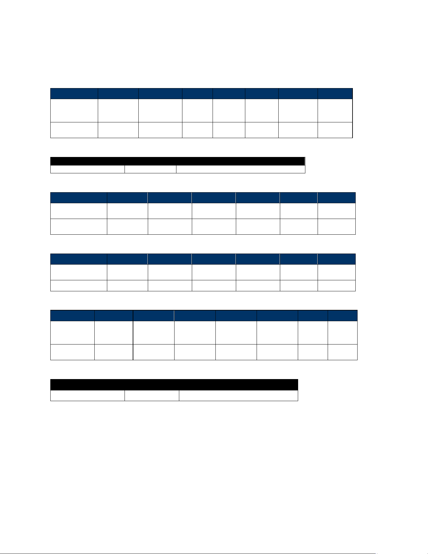
VP7225 User Manual
Page | 50
7.3.1.2. Set/Get Audio Volume (61-32)
The Set/Get Audio Volume command sets and retrieves the reader’s audio volume.
Command Frame (Set Volume)
Byte 0-9
Byte 10
Byte 11
Byte 12
Byte 13
Bye14
Byte 15
Byte 16
Header Tag &
Protocol
Version
Command
Sub-
Command
Data
Length
(MSB)
Data
Length
(LSB)
Data
CRC
(LSB)
CRC
(MSB)
ViVOpayV2\0
61h
32h
00h
01h
See
below
Data Format
Item
Length (bytes)
Description
Set Volume Percent
1
0 - 100 (00h - 14h) in 5% increments.
Response Frame (Set Volume)
Byte 0-9
Byte 10
Byte 11
Byte 12
Byte 13
Byte 14
Byte 15
Header Tag &
Protocol Version
Command
Status Code
Data Length
(MSB)
Data Length
(LSB)
CRC (MSB)
CRC (LSB)
ViVOtech2\0
61h
See status
code table
00h
00h
Command Frame (Get Volume)
Byte 0-9
Byte 10
Byte 11
Byte 12
Byte 13
Byte 14
Byte 15
Header Tag &
Protocol Version
Command
Sub-
Command
Data Length
(MSB)
Data Length
(LSB)
CRC
(LSB)
CRC
(MSB)
ViVOpayV2\0
61h
32h
00h
00h
Response Frame (Get Volume)
Byte 0-9
Byte 10
Byte 11
Byte 12
Byte 13
Bye14
Byte 15
Byte 16
Header Tag &
Protocol
Version
Command
Status Code
Data Length
(MSB)
Data Length
(LSB)
Data
CRC
(MSB)
CRC
(LSB)
ViVOtech2\0
61h
See status
code table
00h
01h
See Below
Data Format
Item
Length (bytes)
Description
Get Volume Percent
1
0-100 (00h - 14h) in 5% increments.

VP7225 User Manual
Page | 51
Get System Info (09-15)
The Get System Info command retrieves system info for individually set items or an entire system.
When retrieving all system info, this command returns only available information.
Byte 0-9
Byte 10
Byte 11
Byte 12
Byte 13
Byte 14
Byte 15
Byte 16
Header Tag &
Protocol Version
Command
Sub-
Command
Data Length
(MSB)
Data Length
(LSB)
Data
CRC
(LSB)
CRC
(MSB)
ViVOpayV2\0
09h
15h
00h
01h
0Dh
Response Frame
Byte 0-9
Byte 10
Byte 11
Byte 12
Byte 13
Bye14 - 26
Byte 27
Byte 28
Header Tag &
Protocol Version
Command
Status
Code
Data Length
(MSB)
Data Length
(LSB)
Data
CRC
(MSB)
CRC (LSB)
ViVOtech2\0
09h
See status
code table
00h
0Dh
ASCII string
Example:
• Get HWID:
TX: 56 69 56 4F 74 65 63 68 32 00 09 15 00 01 0D 26 20
RX: 56 69 56 4F 74 65 63 68 32 00 09 00 00 0D 0D 0B 48 31 38 34 2D
38 30 30 30 30 42 52 AB
Response PCI-ID: 0D 0B 48 31 38 34 2D 38 30 30 30 30 42 (H184-80000B)

VP7225 User Manual
Page | 52
8. RF Interference
Q. Why do I need to know about RF interference?
A. Contactless payment uses radio frequency technology to send card data to a contactless terminal
reader.
Q. How can RF interference affect contactless payment?
A. RF interference can cause data errors. If RF interference is present, contactless payment devices may
operate intermittently or inconsistently.
Q. Where does RF interference come from?
A. Radio frequency interference (RFI) can originate from a wide number of sources at the point-of-sale
(POS). Some examples of sources of RF energy and RF interference include:
AM/FM radio and TV transmitters 2-way radios, pagers
Mobile telephones Power lines, transformers Medical equipment Microwaves
Electromechanical switches
Q. What should I do if I suspect RF interference exists in my environment?
A. Begin by inspecting your environment for possible sources of RF interference.
Q. Do equipment manufacturers test their devices for RF interference?
A. Electronic equipment is tested for RFI sensitivity by the manufacturers. These tests are performed in a
controlled laboratory environment and will often not replicate the types of devices that would be
encountered in your point-of-sale (POS) environment.
Q. What RF levels will impact RF operations?
A. Factors that can cause RF interference vary case-by-case. There are no set rules defining a single RF
level that will cause RFI. RFI depends on the sensitivity of the equipment under consideration, or how
low an interfering signal can be in the presence of the equipment and cause problems.
Equipment can be particularly sensitive to very low signal levels of one frequency and yet be quite
immune to high signal levels of another frequency - so frequency is an important factor. Some electronic
system components are internally shielded and have a very high immunity to interference; but
generally, most equipment has not been so engineered.
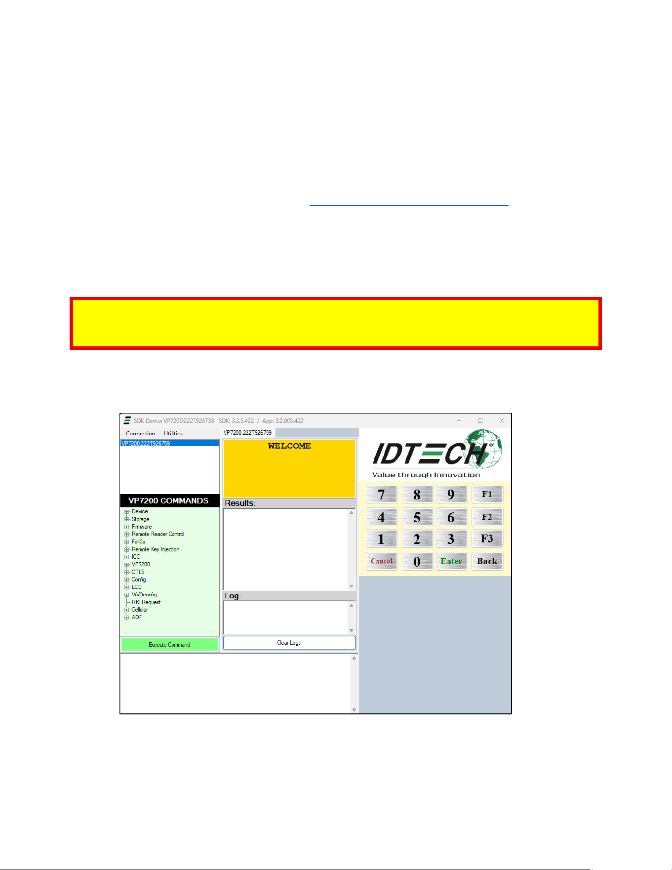
VP7225 User Manual
Page | 53
9. Upgrading Firmware
Use the USB interface to upgrade VP7225 firmware. Contact your ID TECH representative to obtain the
necessary software.
9.1. Preparation
To update the new firmware, you will need:
• PC with an available USB port with the ID TECH Universal SDK Demo application installed.
• A VP7225 reader with a Multi Cable (use the USB port labeled Data).
• Firmware files extracted to your computer; contact your ID TECH representative to receive the
following:
o K81 Bootloader, Firmware, and Device Tree files
o RT1050 Bootloader, Firmware, and Device Tree files
Note: All RT1050 Firmware, and Device Tree files have EXT in their filenames; the RT1050 bootloader
filename contains RT1050. K81 files will not update the RT1050 processor. Likewise, RT1050 files will not
update the K81 processor.
9.2. Loading Files onto the Reader
1. Check and confirm the device is correctly connected to the power source and USB connection.
2. Open the Universal SDK Demo app; the app automatically scans for devices.
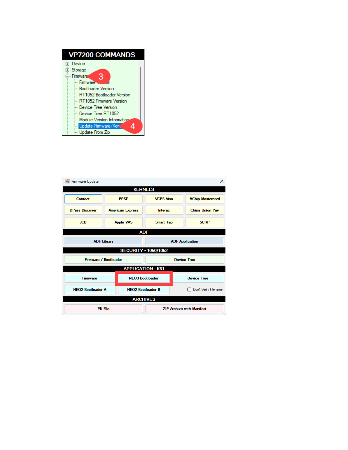
VP7225 User Manual
Page | 54
3. Under Commands, open the Firmware tree.
4. Select Update Firmware/Kernels, then select Execute Commands; the USDK Demo app opens a
Firmware Update dialog.
9.3. Updating K81 Bootloader
1. In the Firmware Update dialog, under APPLICATION - K81, select NEO3 Bootloader.
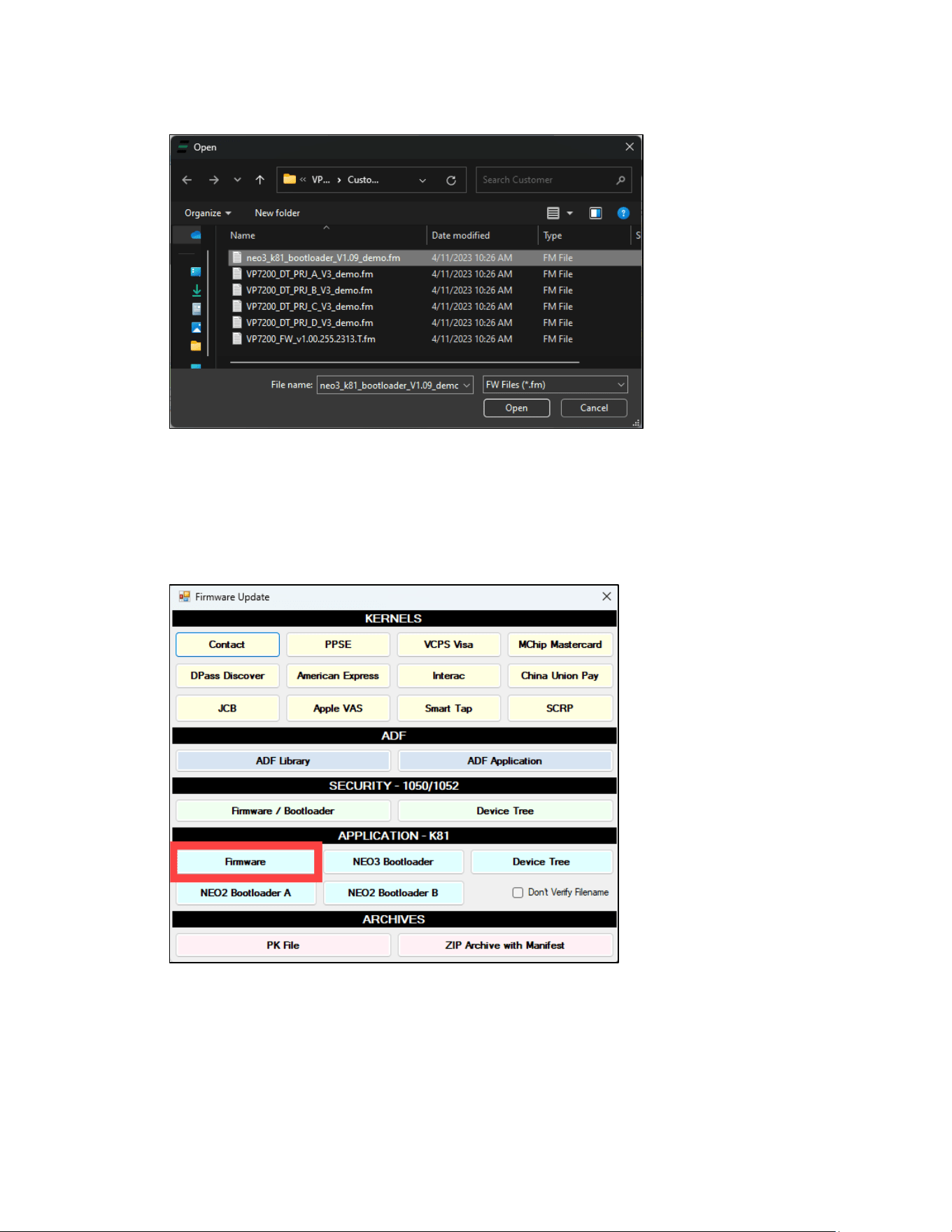
VP7225 User Manual
Page | 55
2. Select the K81 Bootloader file from the extracted location and select Open.
3. The Universal SDK Demo app will update the reader’s K81 firmware; this process may take
several minutes.
4. When the process is complete, the Results pane displays Firmware Update Successful and
Firmware Update Process Completed with Success.
9.4. Updating K81 Firmware
1. In the Firmware Update dialog, under APPLICATION - K81, select Firmware.
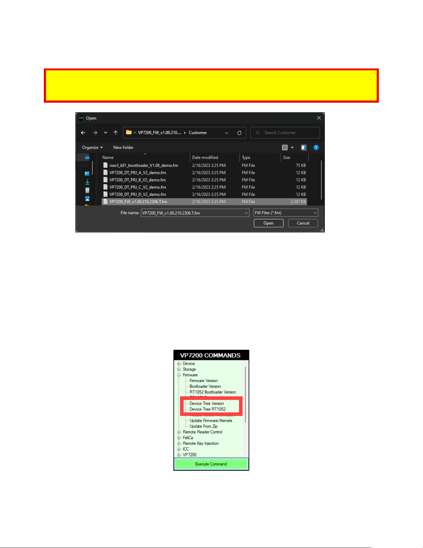
VP7225 User Manual
Page | 56
2. Select the VP7225_FW file and select Open.
Note: Make sure to use the correct type of firmware file for your device:
• Production devices require firmware files ending with .S
• Demo devices require firmware files ending with .T
3. The Universal SDK Demo app will update the reader’s firmware; this process may take several
minutes.
4. When the process is complete, the Results pane displays Firmware Update Successful and
Firmware Update Process Completed with Success.
9.5. Updating K81 Device Tree Firmware
The section below provides steps for updating the K81 Device Tree firmware.
9.5.1. Determining the Correct Device Tree Firmware to Use
Note that VP7225 readers use different Device Tree versions depending on their model numbers. The
Universal SDK Demo app provides an easy way to tell the reader's Device Tree version:
Select the appropriate command (Device Tree Version for K81 and Device Tree RT1052 for RT1050) and
select Execute Command. The Device Tree version prints in the Results pane:
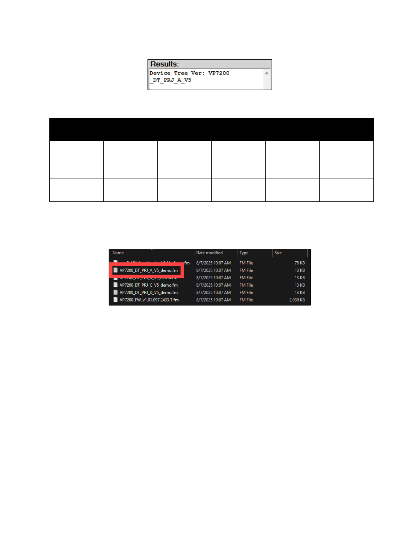
VP7225 User Manual
Page | 57
Device Tree versions can also be determined by model numbers, as listed in the table below:
Model
ID72-818D
ID72-818
ID72-838D
ID72-838
ID72-868D
ID72-868
ID72-808D
ID72-808
ID72-000D
ID72-000
Secure DT model
T or S
T or S
T or S
T or Z
T or S
Project DT model
(RT1050)
A
A
B
C
D
Project DT model
(K81)
A
A
B
C
D
For example, referencing the table above, a reader with a model number of ID72-818 (or ID72-818D for
demo readers) uses version A in the Device Tree. Firmware files have these project version designations
listed in their file names as provided in firmware updates:
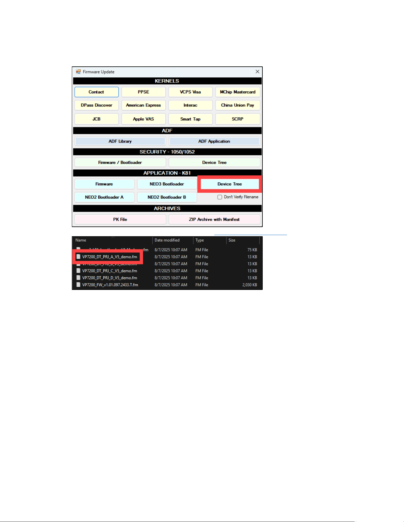
VP7225 User Manual
Page | 58
9.5.2. Updating the Device Tree Firmware
1. In the Firmware Update dialog, under APPLICATION - K81, select Device Tree.
2. Select the K81 VP7225_Ext_DT_PRJ file for your VP7225’s model number and select Open.
3. The Universal SDK Demo app will update the reader’s firmware; this process may take several
minutes.
4. When the process is complete, the Results pane displays Firmware Update Successful and
Firmware Update Process Completed with Success.
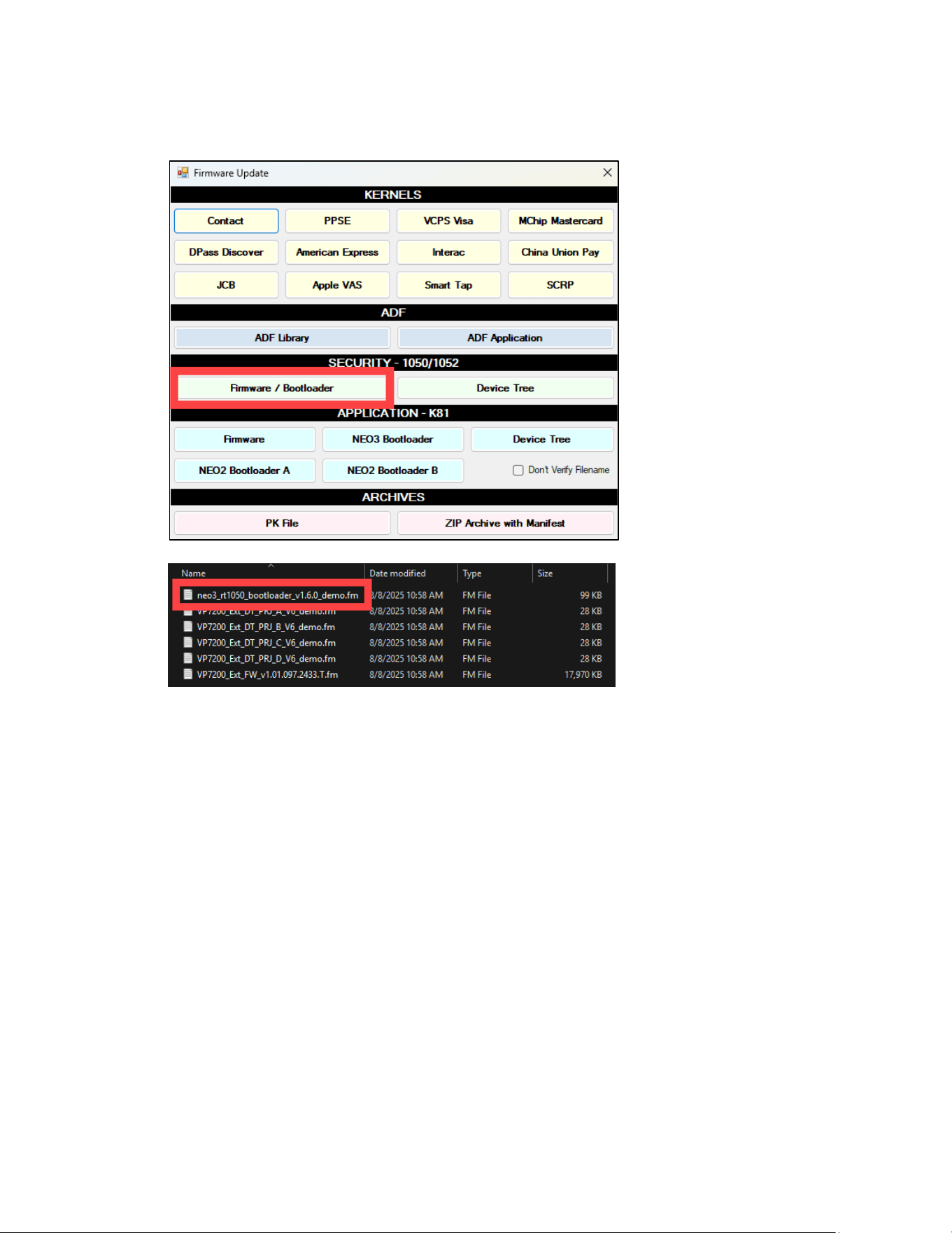
VP7225 User Manual
Page | 59
9.6. Updating RT1050 Bootloader
1. In the Firmware Update dialog, under SECURITY - 1050/1052, select Firmware / Bootloader.
2. Select the neo3_rt1050_bootloader file from the extracted location and select Open.
3. Select the neo3_rt1050_bootloader file and select Open.
4. The Universal SDK Demo app will update the reader’s RT1050 bootloader; this process may take
several minutes.
5. When the process is complete, the Results pane displays Firmware Update Successful and
Firmware Update Process Completed with Success.
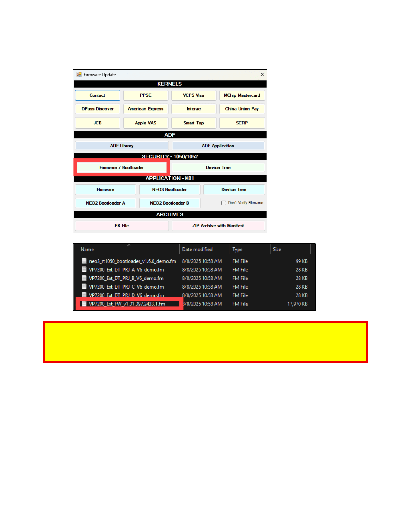
VP7225 User Manual
Page | 60
9.7. Updating RT1050 Firmware
1. In the Firmware Update dialog, under SECURITY - 1050/1052, select Firmware / Bootloader.
2. Select the VP7225_Ext_FW file and select Open.
Note: Make sure to use the correct type of firmware file for your device:
• RT1050 files contain Ext as part of their file name
• Production devices require firmware files ending with .S
• Demo devices require firmware files ending with .T
3. The Universal SDK Demo app will update the reader’s firmware; this process may take several
minutes.
4. When the process is complete, the Results pane displays Firmware Update Successful and
Firmware Update Process Completed with Success.
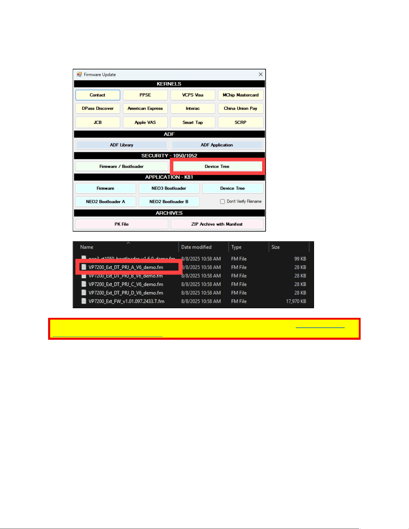
VP7225 User Manual
Page | 61
9.8. Updating RT1050 Device Tree Firmware
3. In the Firmware Update dialog, under SECURITY - 1050/1052, select Device Tree.
4. Select the VP7225_Ext_DT_PRJ file and select Open.
Note: Make sure to use the correct device tree firmware for your reader; see the Determining the
Correct Device Tree Firmware to Use section above for assistance.
5. The Universal SDK Demo app will update the reader’s device tree; this process may take several
minutes.
6. When the process is complete, the Results pane displays Firmware Update Successful and
Firmware Update Process Completed with Success.

VP7225 User Manual
Page | 62
10. Decommissioning SRED Devices
All PCI devices require proper decommissioning prior to device disposal in order to ensure the
protection of all sensitive financial card data. For instructions on decommissioning your device, see
Decommissioning of SRED Devices on the ID TECH Knowledge Base.

VP7225 User Manual
Page | 63
11. Troubleshooting
VP7225 readers are reliable and easy to troubleshoot. The components that may require
troubleshooting include the power supply, the reader itself, and the serial cable. If you are unable to
resolve the problem, contact [email protected] (sending an e-mail to this address will
automatically open a support ticket).
Symptom
Possible Cause
Remedy
General Issues
Reader does not appear
to be powered on (no
LEDs are lit).
Note that when the unit
is expecting a
transaction, the first LED
(on the left) will
illuminate continuously.
Otherwise, in the idle
state, it will blink.
• Reader not powered
on or incorrect voltage.
• Improper use of
internal power supply
provided by the kiosk.
• Check cable connections.
• Verify that power is on and correct voltage and
current are present.
• Make sure that the correct pins are utilized.
• Make sure that the power provided is within the
specified range of the VP7225 reader.
• Make sure that the correct polarity is observed.
• For more information, refer to the Input Voltage
under the Electrical specification section.
• Replace the VP7225.
Reading Cards/Phones
First LED is lit, but beeper
is not audible when
card/fob presented.
• Card/fob/phone not
properly presented.
• RF interference.
• Unsupported card
used.
• Wrong firmware
(contact your local
support
representative).
• Present card/fob/phone closer to the antenna, and
ensure it is parallel to the face of the reader.
• Verify that the card/fob/phone is valid/current.
• Verify that metal is not interfering with the antenna.
• Test with “ViVOcard Contactless Test Card”
• part number 241-0015-03 Rev A.
• Try a different card/fob.
• Check to see if card/fob is damaged.
• Verify that correct firmware is loaded on reader
(local support representative only).
• Power cable plug is fully inserted.
• Replace the VP7225.
Some cards/fobs read,
but not all.
• Possible bad card/fob.
• Unsupported card used.
• Wrong firmware
(contact your local
support representative).
• Check to see if card/fob is damaged.
• Verify that correct firmware is loaded on reader
(local support representative only).
• Present the card in a different orientation.

VP7225 User Manual
Page | 64
Communication to Kiosk
No data is received, or
data is garbled.
• Faulty or incorrect
cable connections.
• Check that the cable connection is secure and in the
correct port on the VP7225.
Load Firmware
Firmware loading
software indicates “open
RS232 failed”
Device is not well
connected to PC or other
software is using serial
interface
• Check the cable connection
• Close other software which is using serial interface
Firmware loading
software indicate “Load
firmware failed”
Device is not well
connected to PC
• Check the cable connection
Firmware loading
software indicates “Send
Command failed”
Bootloader firmware in
device is destroyed
• contact your local support representative to reload
manufacture firmware
11.1. LTE Diagnostic Troubleshooting
The section below provides steps to self-diagnose VP7225 LTE issues. Integrators performing diagnostics
can send these commands independently of each other. When performing diagnostics, power on the
VP7225 and wait thirty to sixty seconds to allow boot-up to complete before sending any commands.
For details on the commands used below, see the NEO 2 Interface Developer's Guide.
11.1.1. Step 1: Check the Firmware and Device Tree Versions
Send the following commands to the reader to check version numbers:
• Get RT1050 Firmware Version (29-80)
o Expected response format: VP7225 FW v1.01.243.2535.T RT1052
• Get Version: Protocol 2 (29-00)
o Expected response format: VP7225 EXT FW v1.01.243.2535.T
• Get Device Tree Version (29-0B-01)
o Expected response format: VP7225_DT_PRJ_B_V10
• Get Device Tree Version (29-0B-11)
o Expected response format: VP7225_Ext_DT_PRJ_B_V10
11.1.2. Step 2: Check the Cellular Configuration
Send the following commands to the reader to verify the cellular connection is enabled:
• Retrieve Cellular Switch Status (D3-02)
o Expected response: 01
• Retrieve Cellular Auto Connect Status (D3-04) (Optional):
o Expected response: 00
11.1.3. Step 3: Check the LTE Working Mode
Send the following commands to verify that airplane mode is turned off (00):
• Get Airplane Mode (D3-12)
o Expected response: 00

VP7225 User Manual
Page | 65
11.1.4. Step 4: Check the Current SIM Card Slot Settings
Send the following command to verify the position the SIM card should be in:
• Retrieve Dual (U)SIM Card Slot Selection (D3-0C)
o Expected response: 01 (indicating the SIM card is in slot 1)

VP7225 User Manual
Page | 66
12. Avoiding Device Tamper Issues
All ID TECH PCI-certified devices integrate tamper switches and disable the card reader when it has been
compromised. The section below describes best practices when handling PCI-secure devices to help
prevent triggering the tamper switches.
Note that following these guidelines does not guarantee a device will not tamper if inadvertently
mishandled or breached. User-induced tamper events will incur repair fees, key injection fees, and
shipping both to and from ID TECH, regardless of warranty status.
12.1. Device Handling Best Practices
• Do not excessively shake the reader.
• Do not drop the reader.
• Do not strike the reader.
• Do not attempt to twist or cause any torsion to the reader.
• Do not expose the reader to extreme heat or cold.
• Do not intentionally subject the reader to electrical shocks.
• Do not submerge the reader in liquids of any type for extended time.
• Do not attempt to open the reader.
• Do not provide power to the reader until all connectors are plugged into the unit.
• Check the device manual to ensure the reader receives the correct power voltage. Providing
power to wires and connectors before plugging them into the device may cause power spikes
that can trigger a tamper event.
• When working with or installing the reader, minimize exposure to static electricity.
12.2. ID TECH Support
In the event the reader does tamper when under warranty, report the tampered device to ID TECH
to troubleshoot and, if needed, be returned to ID TECH for analysis. Contact ID TECH support
at [email protected] for assistance.