MAD
USER MANUAL
Warning notices: Before using this product, please read this manual carefully and keep it for future reference.
MAD50 S1OW W CM

2
CONTENTS
This manual contains valuable tips for the proper use and maintenance of your dehumidifi er.
With a bit of preventive care, you can save time and money throughout the appliance’s lifespan.
The troubleshooting section addresses common issues, allowing you to resolve most problems
quickly before seeking professional service. While these instructions cover many scenarios,
using common sense and adhering to safety guidelines is essential when installing, operating,
and maintaining the unit.
Thank you for choosing Midea!
Before using your new Midea product, please review this manual thoroughly to ensure safe and
effective operation of its features and functions.
CONTENTS ...............................................................................................................2
SAFETY PRECAUTIONS .........................................................................................3
PRODUCT OVERVIEW ...........................................................................................12
PRODUCT INSTALLATION ....................................................................................13
PRODUCT FEATURES ............................................................................................16
SMART FEATURE SETUP .......................................................................................20
CLEANING AND MAINTENANCE .........................................................................24
TROUBLESHOOTING TIPS ....................................................................................29
WARRANTY .............................................................................................................30
CAUTION
• For support, please call the Service Center at 1-888-365-2230.
• This appliance is not intended for use by people (including children) with reduced physical, sensory, or
mental capabilities or lack of experience and knowledge, unless they have been given supervision or
instruction concerning use of the appliance by a person responsible for their safety.
• Children should be supervised to ensure that they do not play with the appliance.
• The appliance shall be installed in accordance with national wiring regulations.
3
SAFETY PRECAUTIONS
Safety and Inspection Guidelines
The following safety guidelines are designed to prevent risks or damage from improper use of the appliance.
Upon arrival, inspect the packaging and appliance to ensure everything is intact for safe operation. If you
notice any damage, contact the retailer or dealer immediately. Please note that modifi cations or alterations to
the appliance are prohibited to ensure safety. Using the appliance in unintended ways may result in hazards
and void any warranty claims.
Explanation of Symbols
Please read through these instructions before you start the installation process. Improper installation can cause
damage to the unit and/or personal property and can be a personal safety hazard.
• Ensure not to exceed the rated capacity of the power outlet or connection device.
• Do not stop or switch off the unit by cutting off the power.
• Do not damage or use an unspecifi ed power cord.
• Do not modify power cord length or share the outlet with other appliances.
• Do not insert or pull out plug with wet hands.
• Do not install the unit in a location that may be exposed to combustible gas.
• Do not place the unit near a heat source.
• Disconnect the power if strange sounds, smell, or smoke comes from it.
• Never try to take apart or repair the unit by yourself.
• Before cleaning, turn off the power and unplug the unit.
• Do not use the unit near fl ammable gas or combustibles, such as gasoline, benzene, thinner, etc.
• Do not drink or use the water drained from the unit.
• Do not take the water bucket out during operation.
• Do not use the unit in small spaces.
• Do not put in places where water may splash onto the unit.
• Place the unit on a level, sturdy section of the fl oor.
• Do not cover the intake or exhaust openings with cloths or towels.
• Care should be taken when using the unit in a room with the following persons: infants, children, elderly
people, and people with reduced physical, sensory, or mental capabilities.
• Do not use in areas where chemicals are handled.
• Never insert your fi nger or other foreign objects into grills or openings. Take special care to warn children
of these dangers.
• Do not place heavy objects on the power cord and take care so that the cord is not compressed.
• Do not climb up on or sit on the unit.
• Always insert the fi lters securely. Clean fi lter once every two weeks. See page 24 for fi lter cleaning instructions.
• lf water enters the unit, turn the unit off and disconnect the power, contact a qualifi ed service technician.
• Do not place fl ower vases or other water container fi lled on top of the unit.
• Do not use extension cords.
WARNING
WARNING
This signal indicates a medium-level hazard that, if not avoided, could result in death or
serious injury.
CAUTION
This signal indicates a hazard with a low degree of risk which, if not avoided, may result in a
minor or moderate injury.

4
• This unit is not intended for use by persons (including children) with reduced physical, sensory or
mental capabilities or lack of experience and knowledge, unless they have been given supervision or
instruction concerning use of the appliance by a person responsible for their safety.
• Children should be supervised to ensure that they do not play with the unit.
• If the supply cord is damaged, it must be replaced by the manufacturer, its service agent or similarly
qualified persons in order to avoid a hazard.
• Prior to cleaning or other maintenance, the unit must be disconnected from the power supply.
• Do not install the unit in a location that may be exposed to combustible gas. If combustible gas
accumulates around the unit, it may cause fire.
• lf the appliance is knocked over during use, turn off the unit and unplug it from the main power supply
immediately. Visually inspect the unit to ensure there is no damage. If you suspect the unit has been
damaged, contact a technician or customer service for assistance.
• Our product should not be used in a water damaged environment.
• ln a thunderstorm, the power must be cut off to avoid damage to the unit due to lightning.
• Do not run cord under carpeting. Do not cover cord with throw rugs, runners, or similar coverings. Do
not route cord under furniture or appliances. Arrange cord away from areas and where it will not be
tripped over.
• Do not operate unit with a damaged cord or plug. Discard unit or return to an authorized service facility
for examination and/or repair.
• To reduce the risk of fi re or electric shock, do not use this unit with any solid-state speed control device.
• The unit shall be installed in accordance with national wiring regulations.
• Contact the authorized service technician for repair or maintenance of this unit.
• Turn off the unit when not in use.
• The manufacturer’s nameplate is located on the panel of the unit and contains electrical and other
technical data specific to this unit.
• Be sure the unit is properly grounded. To minimize shock and fi re hazards, proper grounding is important.
• The power cord is equipped with a three-prong grounding plug for protection against shock hazards.
• Your unit must be used in a properly grounded wall receptacle. If the wall receptacle you intend to use
is not adequately grounded or protected by a time delay fuse or circuit breaker (please refer to the
nameplate for the electrical data), have a qualified electrician install the proper receptacle.
• The unit’s circuit board (PCB) is designed with a fuse to provide overcurrent protection specifi cations of
the fuse are printed on the circuit board, such as: T 3.15A/250V (or 350V), etc.
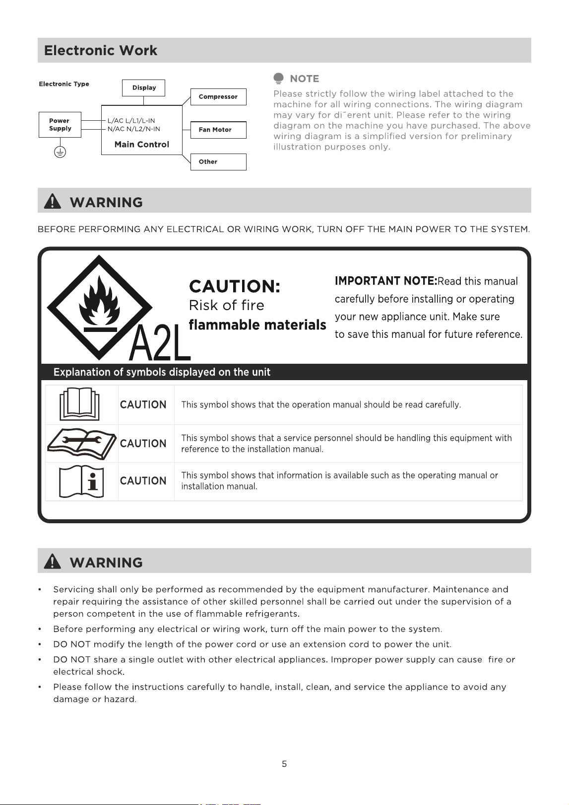
CAUTION

6
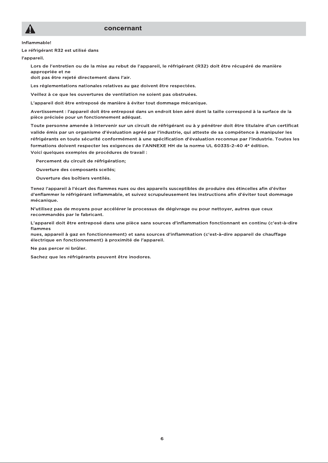
Flammable!
Refrigerant R32 is used within the unit.
• When maintaining or disposing the unit, the refrigerant (R32) shall be recovered properly, shall not
discharge to air directly.
• Compliance with national gas regulations shall be observed.
• Keep ventilation openings clear of obstruction.
• The appliance shall be stored so as to prevent mechanical damage from occurring.
• A warning that the unit shall be stored in a well-ventilated area where the room size corresponds to the
room area as specifi ed for operation.
Examples for such working procedures are:
• Breaking into the refrigerating circuit;
• Opening of sealed components;
• Opening of ventilated enclosures.
• Keep the appliance away from open fl ames or devices that may cause sparks to avoid igniting the
fl ammable refrigerant, and follow instructions carefully to prevent mechanical damage.
• Do not use means to accelerate the defrosting process or to clean, other than those recommended by the
manufacturer.
• The unit shall be stored in a room without continuously operating ignition sources (i.e. open fl ames, an
operating gas appliance) and ignition sourcesor (i.e. an operating electric heater) close to the unit.
• Do not pierce or burn.
• Be aware that the refrigerants may not contain an odor.
WARNING (for using R32 refrigerant)
• Any person who is involved with working on or breaking into a refrigerant circuit should hold a current
valid certificate from an industry-accredited assessment authority, which authorizes their competence to
handle refrigerants safely in accordance with an industry recognized assessment specification. All training
shall follow the ANNEX HH requirements of UL 60335-2-40 4th Edition.

7
How To Handle Equipment Containing Flammable Refrigerants
1. Transport of equipment containing fl ammable refrigerants.
See transport regulations.
2. Marking of equipment using signs.
See local regulations.
3. Disposal of equipment using fl ammable refrigerants.
See national regulations.
4. Storage of equipment/appliances.
5. Storage of packed (unsold) equipment.
Storage package protection should be constructed such that mechanical damage to the equipment inside
the package will not cause a leak of the refrigerant charge. The maximum number of pieces of equipment
permitted to be stored together will be determined by local regulations.
6. Information on servicing.
1) Checks to the area
Prior to beginning work on systems containing fl ammable refrigerants, safety checks are necessary
to ensure that the risk of ignition is minimized. For repair to the refrigerating system, the following
precautions shall be complied with prior to conducting work on the system.
2) Work procedure
Work shall be undertaken under a controlled procedure so as to minimize the risk of a fl ammable gas or
vapor being present while the work is being performed.
3) General work area
All maintenance staff and others working in the local area shall be instructed on the nature of work being
carried out. Work in confi ned spaces shall be avoided. The area around the workspace shall be sectioned
of. Ensure that the conditions within the area have been made safe by control of fl ammable material.
4) Checking for presence of refrigerant
The area shall be checked with an appropriate refrigerating detector prior to and during work, to ensure the
technician is aware of potentially fl ammable atmospheres. Ensure that the leak detection equipment being
used is suitable for use with fl ammable refrigerants. (i.e. non-sparkling, adequately sealed or intrinsically safe).
5) Presence of fi re extinguisher
If any hot work is to be conducted on the refrigeration equipment or any associated parts, appropriate
fi re extinguishing equipment shall be available to hand. Have a dry powder or CO2 fi re extinguisher
adjacent to the charging area.
6) No ignition sources
During work on refrigeration systems involving pipes containing or having contained fl ammable
refrigerants, individuals must avoid using any ignition sources that could potentially cause fi re or
explosion risks. This includes maintaining a safe distance from the installation, repair, removal, and
disposal sites where fl ammable refrigerants may be present. Before commencing work, the surrounding
area must be inspected to ensure there are no fl ammable hazards or ignition risks. Additionally, ‘No
Smoking’ signs should be prominently displayed.
7) Ventilated area
Before initiating any system breach or conducting hot work, ensure the area is outdoors or properly
ventilated. Adequate ventilation must be maintained throughout the duration of the work to safely
disperse any released refrigerant, ideally venting it externally into the atmosphere.
The storage of the appliance should be in accordance with the applicable regulations or instructions,
whichever is more stringent.

8
8) Checks to the refrigerating equipment
When replacing electrical components, ensure they are suitable for their intended purpose and meet
the correct specifi cations. Always adhere to the manufacturer’s maintenance and service guidelines. If
uncertain, seek guidance from the manufacturer’s technical department. The following checks should be
performed for installations utilizing fl ammable refrigerants:
The refrigerant charge must align with the size of the room where refrigerant-containing parts are
installed. Ensure ventilation systems and outlets operate effectively and remain unobstructed. If using
an indirect refrigerating circuit, verify the presence of refrigerant in the secondary circuit. Equipment
markings must be visible and legible at all times; any illegible markings or signs should be promptly
corrected. Refrigeration pipes and components should be installed in locations unlikely to expose them
to corrosive substances, unless they are inherently corrosion-resistant materials or adequately protected
against corrosion.
9) Checks to electrical devices
Repair and maintenance to electrical components shall include initial safety checks and component
inspection procedures. If a fault exists that could compromise safety, then no electrical supply shall be
connected to the circuit until it is satisfactorily addressed. If the fault cannot be corrected immediately
but it is necessary to continue operation, an adequate temporary solution shall be used. This shall be
reported to the owner of the equipment so all parties are advised.
Initial safety checks shall include:
That capacitors are discharged: this shall be done in a safe manner to avoid possibility of sparking; That there
are no live electrical components and wiring are exposed while charging, recovering or purging the system;
That there is continuity of earth bonding.
7. Sealed electrical components shall be replaced.
8. Intrinsically safe components must be replaced.
9. Cabling.
Check that cabling will not be subject to wear, corrosion, excessive pressure, vibration, sharp edges or any
other adverse environmental effects. The check shall also take into account the effects of aging or continual
vibration from sources such as compressors or fans.

9
10. Detection of fl ammable refrigerants.
Under no circumstances should potential sources of ignition be used during the search for or detection
of refrigerant leaks. This includes avoiding the use of halide torches or any other detectors that utilize
naked fl ames.
The following leak detection methods are deemed acceptable for systems containing fl ammable
refrigerants. Electronic leak detectors shall be used to detect fl ammable refrigerants, but the sensitivity
may not be adequate, or may need re-calibration.
(Detection equipment shall be calibrated in a refrigerant-free area).
Ensure that the detector is not a potential source of ignition and is suitable for the refrigerant used. Leak
detection equipment shall be set at a percentage of the LFL of the refrigerant and shall be calibrated to the
refrigerant employed and the appropriate percentage of gas (25% maximum) is confi rmed. Leak detection
fl uids are suitable for use with most refrigerants but the use of detergents containing chlorine shall be
avoided as the chlorine may react with the refrigerant and corrode the copper pipe-work.
If a leak is suspected, all naked fl ames shall be removed/extinguished. If a refrigerant leak requiring brazing
is detected, all refrigerant must be recovered from the system, or isolated (using shut-off valves) in a part of
the system away from the leak. Removal of refrigerant shall be according to “Removal and evacuation”.
11. Removal and evacuation.
When breaking into the refrigerant circuit to make repairs - or for any other purpose - conventional
procedures shall be used. However, for fl ammable refrigerants it is important that best practice be
followed, since fl ammability is a consideration. The following procedure shall be adhered to:
- safely remove refrigerant following local and national regulations;
- evacuate;
- purge the circuit with inert gas (optional for A2L);
- evacuate (optional for A2L);
- continuously fl ush or purge with inert gas when using fl ame to open circuit; and
- open the circuit.
The refrigerant charge must be recovered into appropriate recovery cylinders if venting is prohibited by
local and national codes. For appliances containing fl ammable refrigerants, the system should be purged
with non-fl ammable refrigerants that are oxygen-free. Under no circumstances should compressed air or
oxygen be used for purging refrigerant systems.
For appliances containing fl ammable refrigerants, purging must be conducted by initially breaking the
vacuum in the system with oxygen-free nitrogen. Nitrogen should be continuously added until the desired
working pressure is reached, then vented to the atmosphere. Subsequently, the system should be pulled
down to a vacuum (this step is optional for A2L refrigerants). This purging process should be repeated until
no refrigerant remains in the system (optional for A2L refrigerants). After the fi nal charge of oxygen-free
nitrogen is used, the system should be vented to atmospheric pressure to facilitate further work.
The outlet for the vacuum pump shall not be close to any potential ignition sources, and ventilation shall
be available.
The refrigerant charge shall be recovered into the correct recovery cylinders if venting is not allowed by
local and national codes. For appliances containing fl ammable refrigerants, the system shall be purged
with oxygen-free nitrogen to render the appliance safe for fl ammable refrigerants. This process might
need to be repeated several times. Compressed air or oxygen shall not be used for purging refrigerant
systems. For appliances containing fl ammable refrigerants, refrigerants purging shall be achieved by
breaking the vacuum in the system with oxygen-free nitrogen and continuing to fi ll until the working
pressure is achieved, then venting to atmosphere, and fi nally pulling down to a vacuum (optional for A2L).
This process shall be repeated until no refrigerant is within the system (optional for A2L). When the fi nal
oxygen-free nitrogen charge is used, the system shall be vented down to atmospheric pressure to enable
work to take place. Ensure that the outlet for the vacuum pump is not close to any potential ignition
sources and that ventilation is available.

10
12. Charging procedures.
In addition to conventional charging procedures, the following requirements shall be followed. Ensure that
contamination of different refrigerants does not occur when using charging equipment. Hoses or lines shall
be as short as possible to minimize the amount of refrigerant contained in them. Cylinders shall be kept
in an appropriate position according to the instructions. Ensure that the refrigeration system is earthed
prior to charging the system with refrigerant. Label the system when charging is complete (if not already).
Extreme care shall be taken not to overfi ll the refrigeration system. Prior to recharging the system it shall
be pressure tested with OFN. The system shall be leak tested on completion of charging but prior to
commissioning. A follow up leak test shall be carried out prior to leaving the site.
13. Decommissioning.
Before carrying out this procedure, it is essential that the technician is completely familiar with the
equipment and all its detail. It is recommended good practice that all refrigerants are recovered safely.
Before commencing the task, it is essential to take oil and refrigerant samples in case analysis is needed
before reclaimed refrigerant can be reused. Ensure electrical power is available prior to starting the task.
a. Become familiar with the equipment and its operation.
b. Isolate system electrically.
c. Before attempting the procedure ensure that mechanical handling equipment is available if required for
handling refrigerant cylinders;
All personal protective equipment is available and being used correctly; The recovery process is supervised
at all times by a competent person; Recovery equipment and cylinders conform to the appropriate standards.
d. If possible, pump down the refrigerant system.
e. If a vacuum is not possible, make a manifold so that refrigerant can be removed from various parts of
the system.
f. Make sure that cylinder is situated on the scales before recovery takes place.
g. Start the recovery machine and operate in accordance with instructions.
h. Do not overfi ll cylinders. (No more than 80 % volume liquid charge).
i. Do not exceed the maximum working pressure of the cylinder, even temporarily.
j. When the cylinders have been fi lled correctly and the process completed, make sure that the cylinders and
the equipment are removed from site promptly and all isolation valves on the equipment are closed off.
k. Recovered refrigerant shall not be charged into another refrigeration system unless it has been cleaned
and checked.
14. Labeling.
Equipment shall be labeled stating that it has been de-commissioned and emptied of refrigerant. The label
shall be dated and signed.
Ensure that there are labels on the equipment stating the equipment contains fl ammable refrigerant.

11
Recovery.
When removing refrigerant from a system, either for servicing or decommissioning, it is recommended
good practice that all refrigerants are removed safely.
When transferring refrigerant into cylinders, ensure that only appropriate refrigerant recovery cylinders
are employed. Ensure that the correct number of cylinders for holding the total system charge is available.
All cylinders to be used are designated for the recovered refrigerant and labeled for that refrigerant (i.e.
special cylinders for the recovery of refrigerant). Cylinders shall be complete with pressure-relief valve and
associated shut-off valves in good working order. Empty recovery cylinders are evacuated and, if possible,
cooled before recovery occurs.
The recovery equipment shall be in good working order with a set of instructions concerning the
equipment that is at hand and shall be suitable for the recovery of the fl ammable refrigerant. If in doubt, the
manufacturer should be consulted. In addition, a set of calibrated weighing scales shall be available and in
good working order. Hoses shall be complete with leak-free disconnect couplings and in good condition.
The recovered refrigerant shall be processed according to local legislation in the correct recovery cylinder,
and the relevant waste transfer note arranged. Do not mix refrigerants in recovery units and especially not
in cylinders.
If compressors or compressor oils are to be removed, ensure that they have been evacuated to an
acceptable level to make certain that fl ammable refrigerant does not remain within the lubricant. The
compressor body shall not be heated by an open fl ame or other ignition sources to accelerate this process.
When oil is drained from a system, it shall be carried out safely.
Non-duct connected appliances containing A2L refrigerants with the supply and return air openings in the
conditioned space may have the body of the appliance installed in open areas such as false ceilings not
being used as return air plenums, as long as the conditioned air does not directly communicate with the air
of the false ceiling.
15.
13
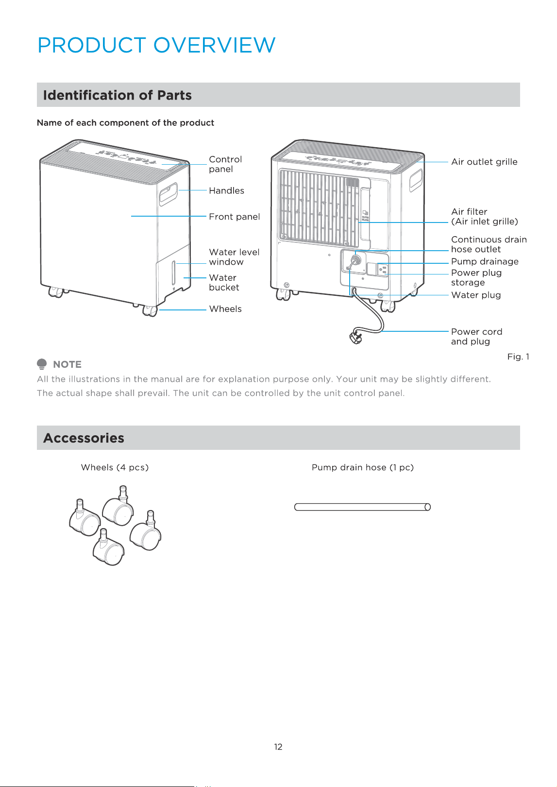
PRODUCT INSTALLATION
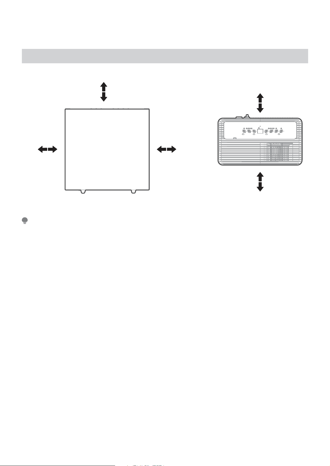
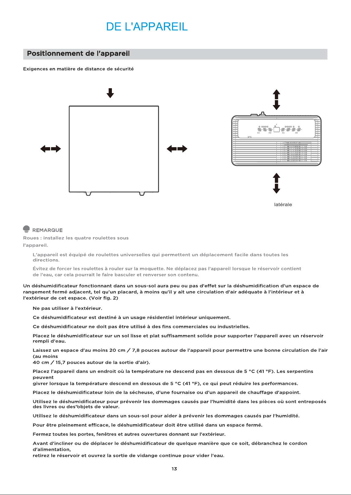
Positioning the Unit
A dehumidifier operating in a basement will have little or no effect in drying an adjacent enclosed storage
area, such as a closet, unless there is adequate circulation of air in and out of the area. (See Fig. 2)
• Do not use outdoors.
• This dehumidifer is intended for indoor residential applications only.
• This dehumidifer should not be used for commercial or industrial applications.
• Place the dehumidifi er on a smooth, level fl oor strong enough to support the unit with a full bucket of water.
• Allow at least 20cm / 7.8in of air space on all sides of the unit for good air circulation (at least 40cm /
15.7in of air space on air outlet).
• Place the unit in an area where the temperature will not fall below 5°C (41°F). The coils may develop
frost when temperatures drop below 5°C (41°F), potentially reducing performance.
• Place the dehumidifi er away from the dryer, heater or radiator.
• Use the dehumidifi er to prevent moisture damage in areas where books or valuables are stored.
• Use the dehumidifi er in a basement to help prevent moisture damage.
• The dehumidifi er must be operated in an enclosed area to be most effective.
• Close all doors, windows and other outside openings to the room.
• Before tilting or moving the dehumidifi er in any way, disconnect the power cord, take out the bucket,
and open the continuous drain outlet to empty the water.
Fig. 2
Safe distance requirements
Wheels - install all four on the bottom of the unit.
• The unit is equipped with universal wheels that allow fl exible movement in all directions.
• Avoid forcing the wheels to move over carpet. Do not move the unit when the bucket contains water, as
this may cause tipping and spillage.
NOTE
20cm
or more
20cm
or more
40cm
or more
40cm
or more
40cm
or more
Front view Top view
20cm / 7.8 in
or more
40cm / 15.7in
or more
40cm / 15.7in
or more
40cm / 15.7in
or more
20cm / 7.8 in
or more
14
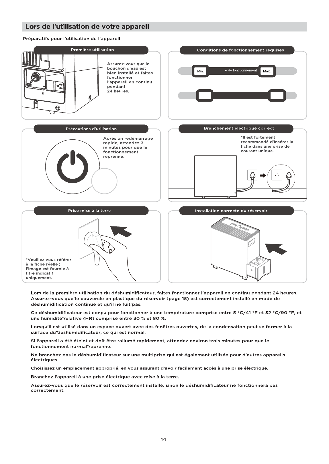
When Using Your Product
• When fi rst using the dehumidifi er, operate the unit continuously for 24 hours. Ensure that the plastic cover
of the bucket (Page 15) is securely installed in continuous dehumidifi cation mode and does not leak.
• This dehumidifi er is designed to operate with a working environment between 5°C/41°F and 32°C/90°F,
and between 30% (RH) and 80% (RH).
• When use in open space with open windows, condensation may form on the surface of the dehumidifi er,
which is normal.
• lf the unit has been switched off and needs to be switched on again quickly, allow approximately three
minutes for the correct operation to resume.
• Do not connect the dehumidifi er to a multiple socket outlet, which is also being used for other electrical
appliances.
• Select a suitable location, making sure you have easy access to an electrical outlet.
• Plug the unit into an electrical socket-outlet with ground connection.
• Make sure the water bucket is correctly fi tted otherwise the dehumidifi er will not operate properly.
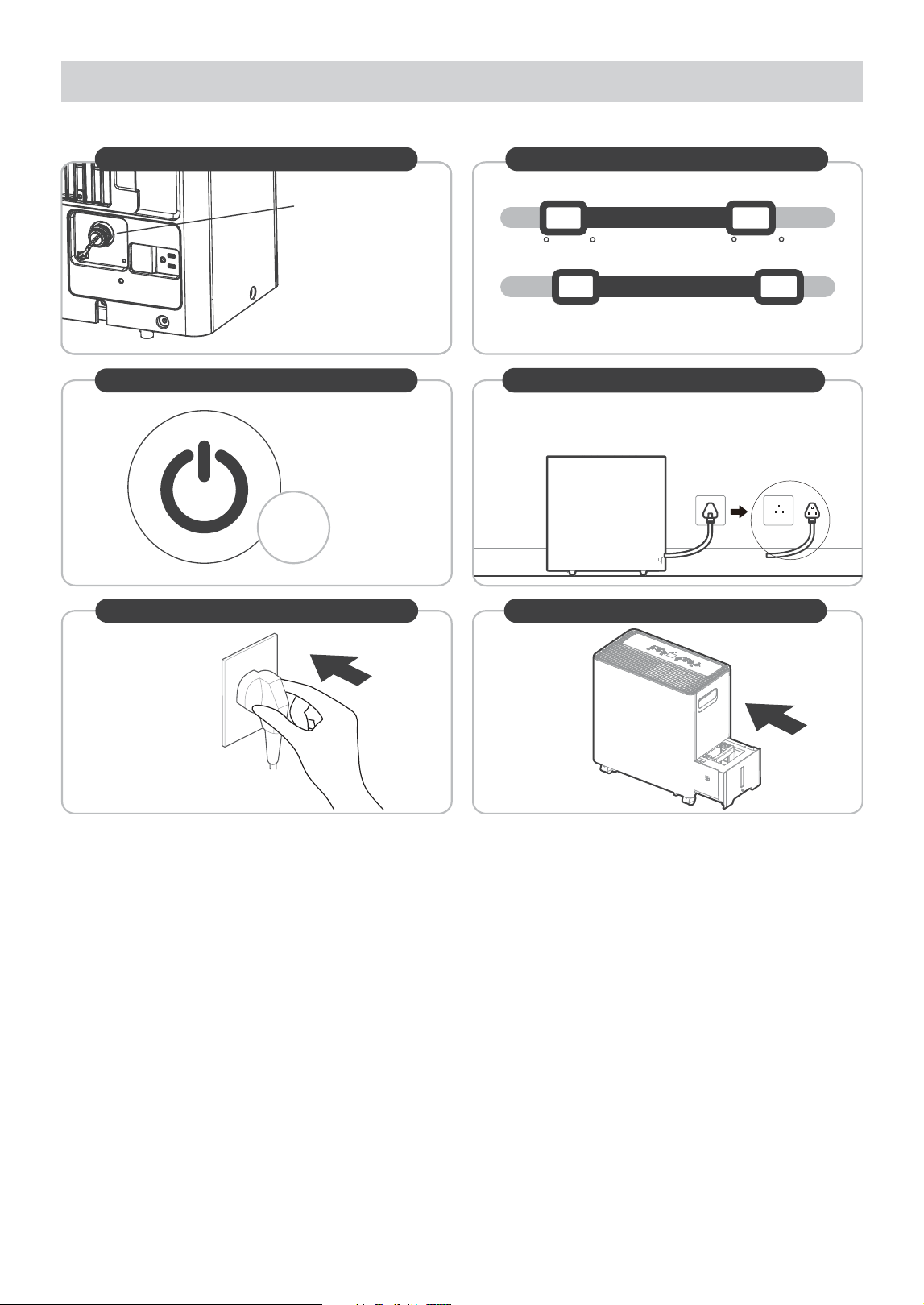
Preparations for product use
3min
After a quick restart,
wait 3 minutes for the
operation to resume.
*Please refer to the
actual plug; image
is for reference only.
30% (RH) 80% (RH)
Operating TEMP.
Operating Humidity
Min.
Min.
Max.
Max.
5 C/41 F
32 C/90 F
Working condition requirement
Precautions for use
First time using
Ensure the water plug
is securely installed
and operate the unit
continuously for
24 hours.
Ground connection Proper installation of water bucket
Correct power connection
*It is highly recommended
to insert the plug into a
single socket outlet.
15
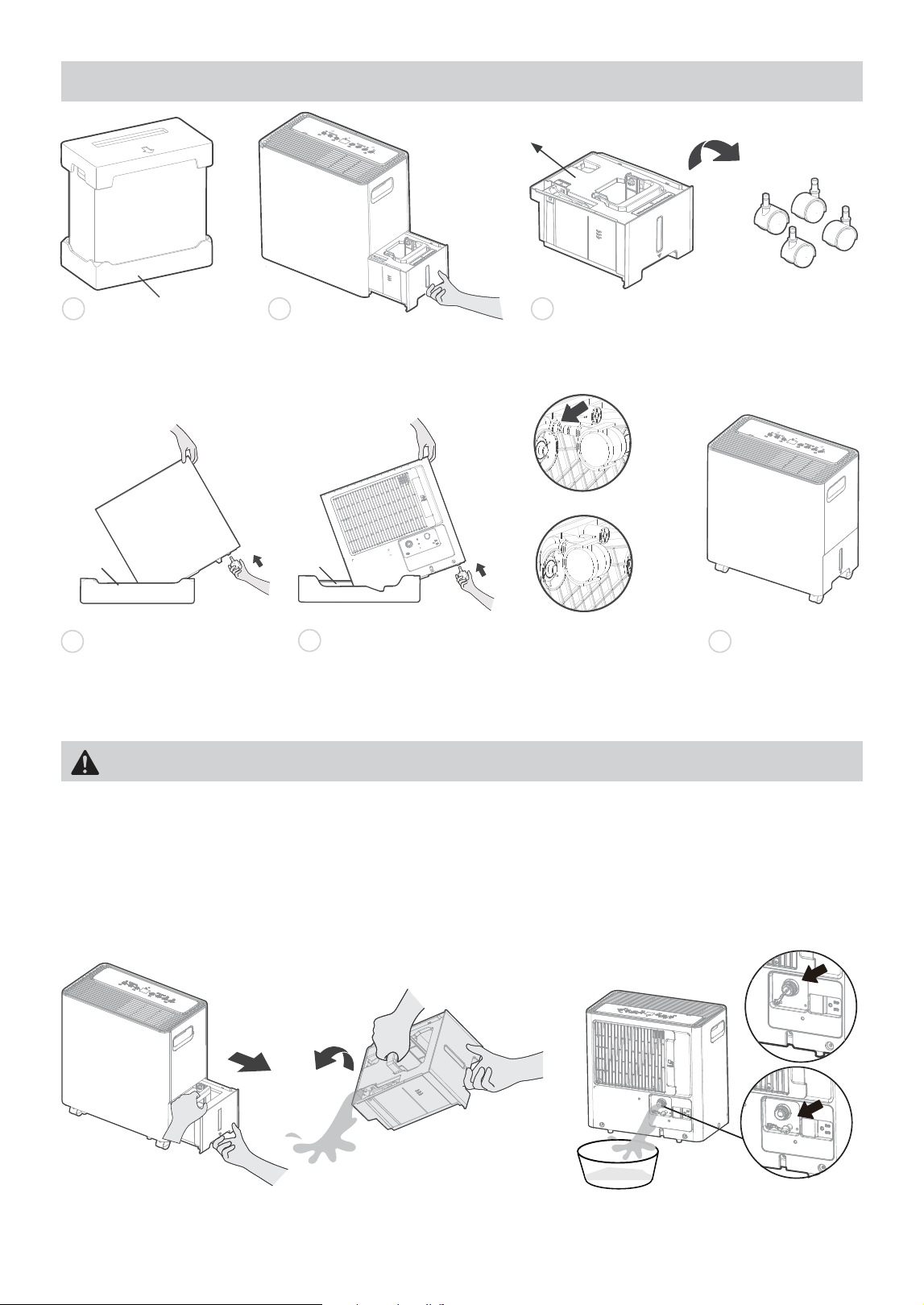
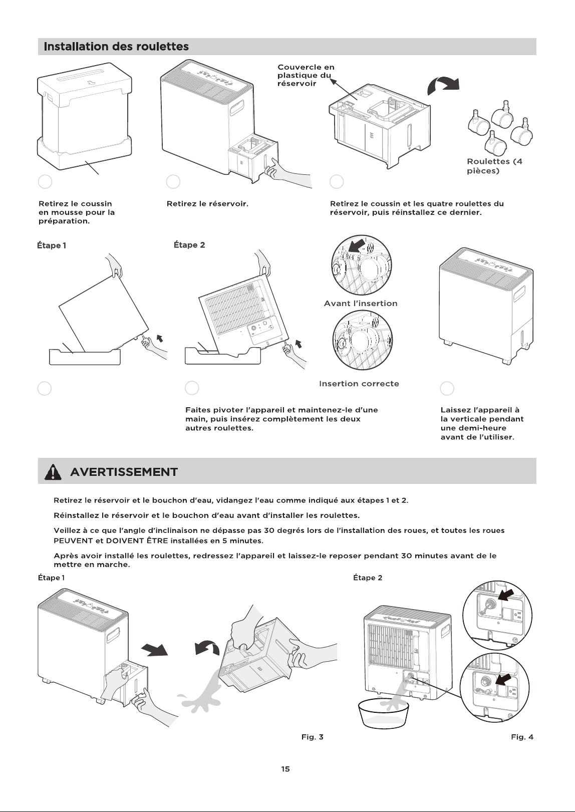
Wheels Installation
• Remove the bucket and water plug, drain the water as shown in step 1 and step 2.
• Reinstall the bucket and water plug before installing the wheels.
• Ensure the tilt angle does not exceed 30 degrees during wheels installation, and all wheels MUST BE
installed within 5 minutes.
• After installing the wheels, set the unit upright and let it rest for 30 minutes before starting the unit.
WARNING
Step 1
Step 2
Fig. 3 Fig. 4
2 3
Pull out the water bucket.
1
Remove the foam pad
for preparation.
Remove the cushion pad and four wheels from
the bucket, then reinstall the water bucket.
Wheels (4 pc)
Plastic cover of
the bucket
4 6
Tilt the unit on its side and
hold it with one hand, then
fully insert two wheels.
Leave the unit
standing up for half
an hour before use.
Rotate the unit and hold it with one hand, then
fully insert the other two wheels.
Before inserting
Correctly inserted
5
Foam pad
Step 1
Step 2
Foam pad
Foam pad
16
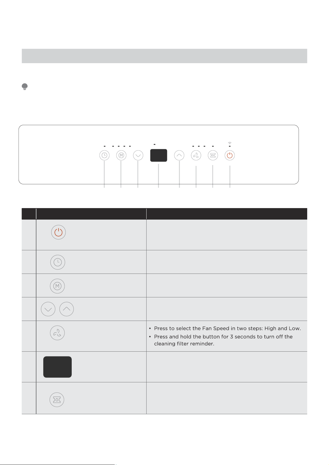
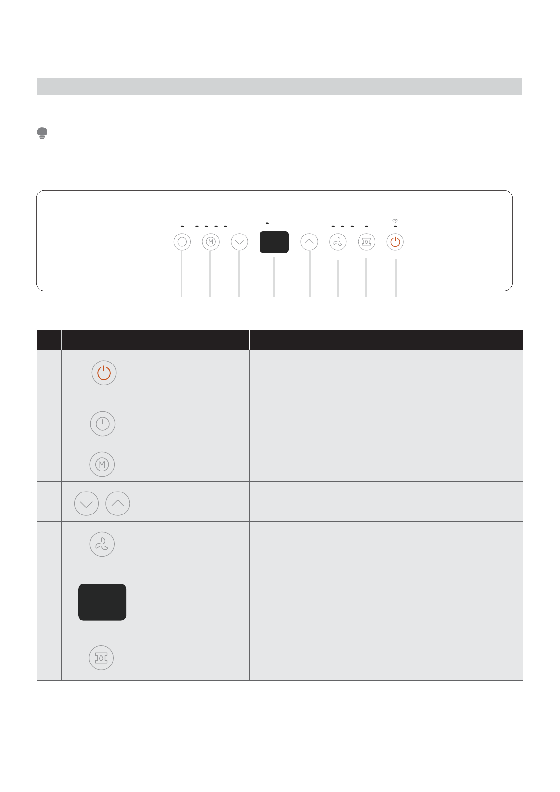
Control Panel Features
PRODUCT FEATURES
Description
1 ON / OFF
• Press to turn unit on or off.
• Press for 3 sec to initiate wireless connection mode.
2 TIMER Button • Press to turn unit Auto Start/Stop.
3 Mode Button
• Press to choose operating mode in a sequence:
Set → Cont. → Dryer → Comfort
4
UP / DOWN
Buttons
• Press to set humidity and timer.
5 FAN Button
6
LED Display
• Show the ambient humidity and set humidity, set time
(when timer function is used), and the error codes.
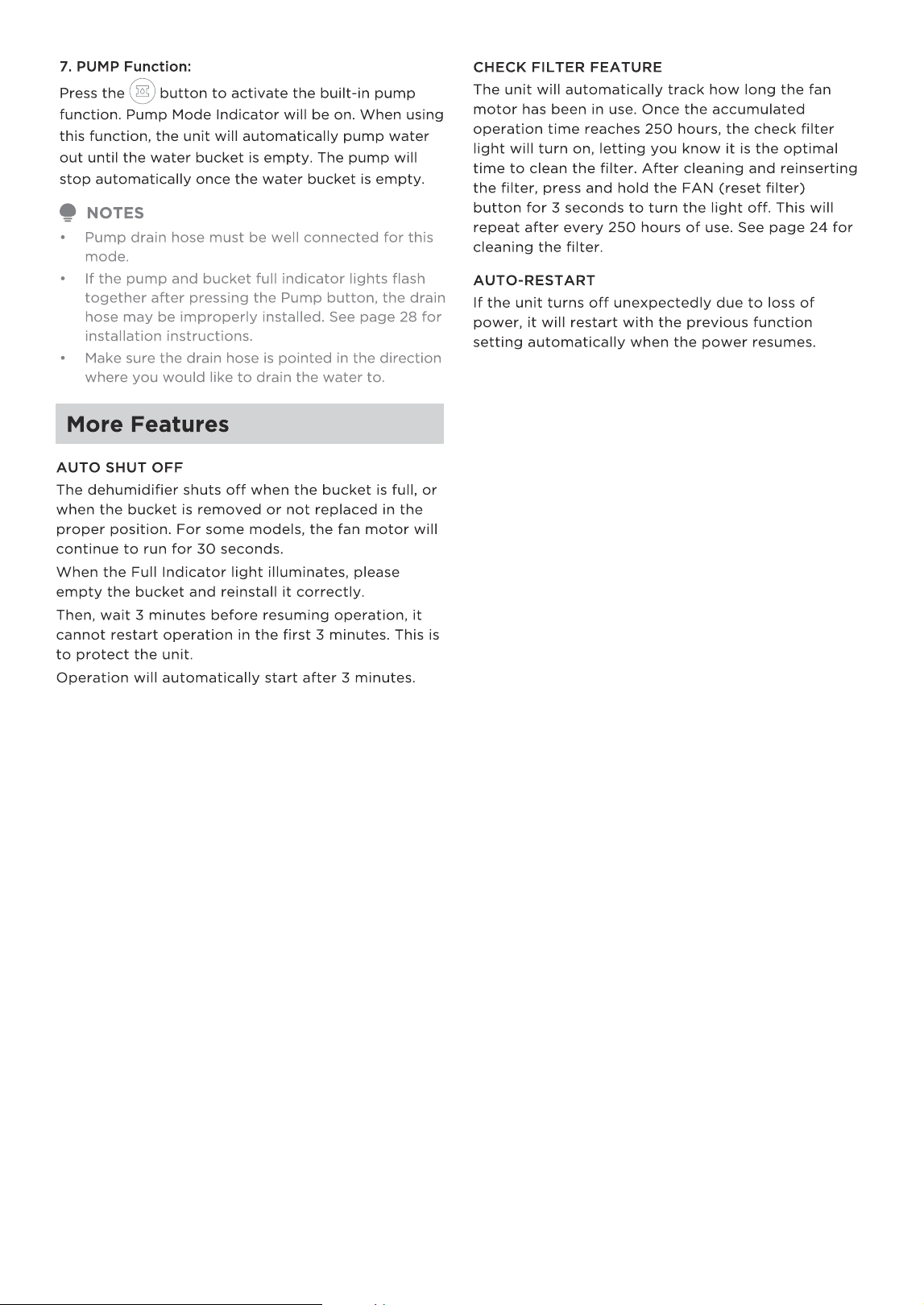
7 PUMP Button
• Press to activate the built-in pump function.
The following control panels are for illustrative purposes only. The control panel of the unit you purchased
may vary slightly depending on the model. Some indicators or buttons may not be present. The physical
shape of the unit will remain consistent.
NOTE
Operation Display
32 1764 4 5
Minuterie
Timer
Déshumidifier
Set
Cont.
Cont.
Plus sec
Dryer
Comfort
Confort
Full
Plein
Faible Élevée Filtre Pompe
Low High Filter Pump
Reset filter (3s)
Connect (5s)
Réinitialiser le filtre (3s)
Marche/Arrêt (5s)
Reset filter (3s)
Réinitialiser le filtre (3s)
Connect (5s)
Marche/Arrêt (5s)
17
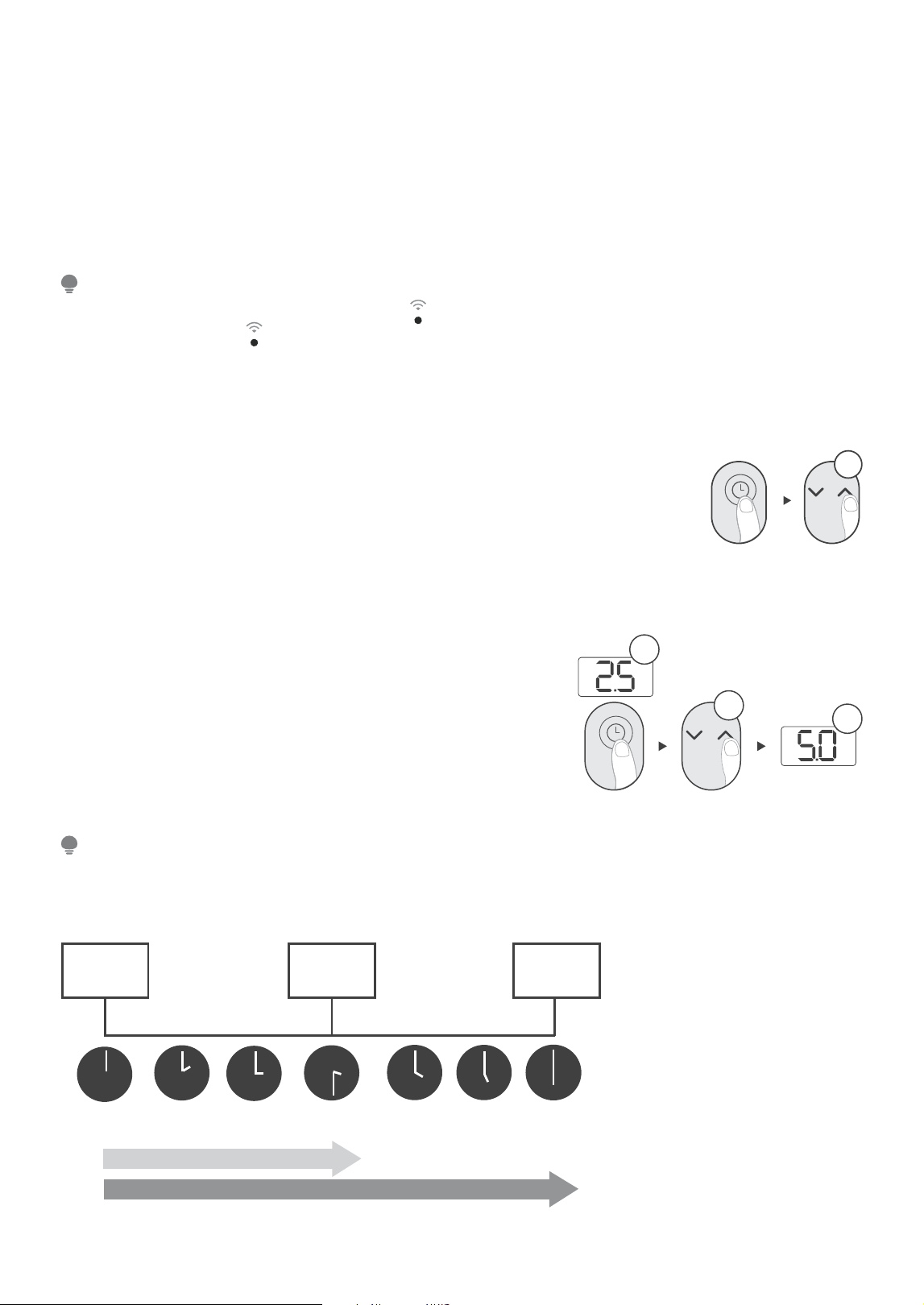
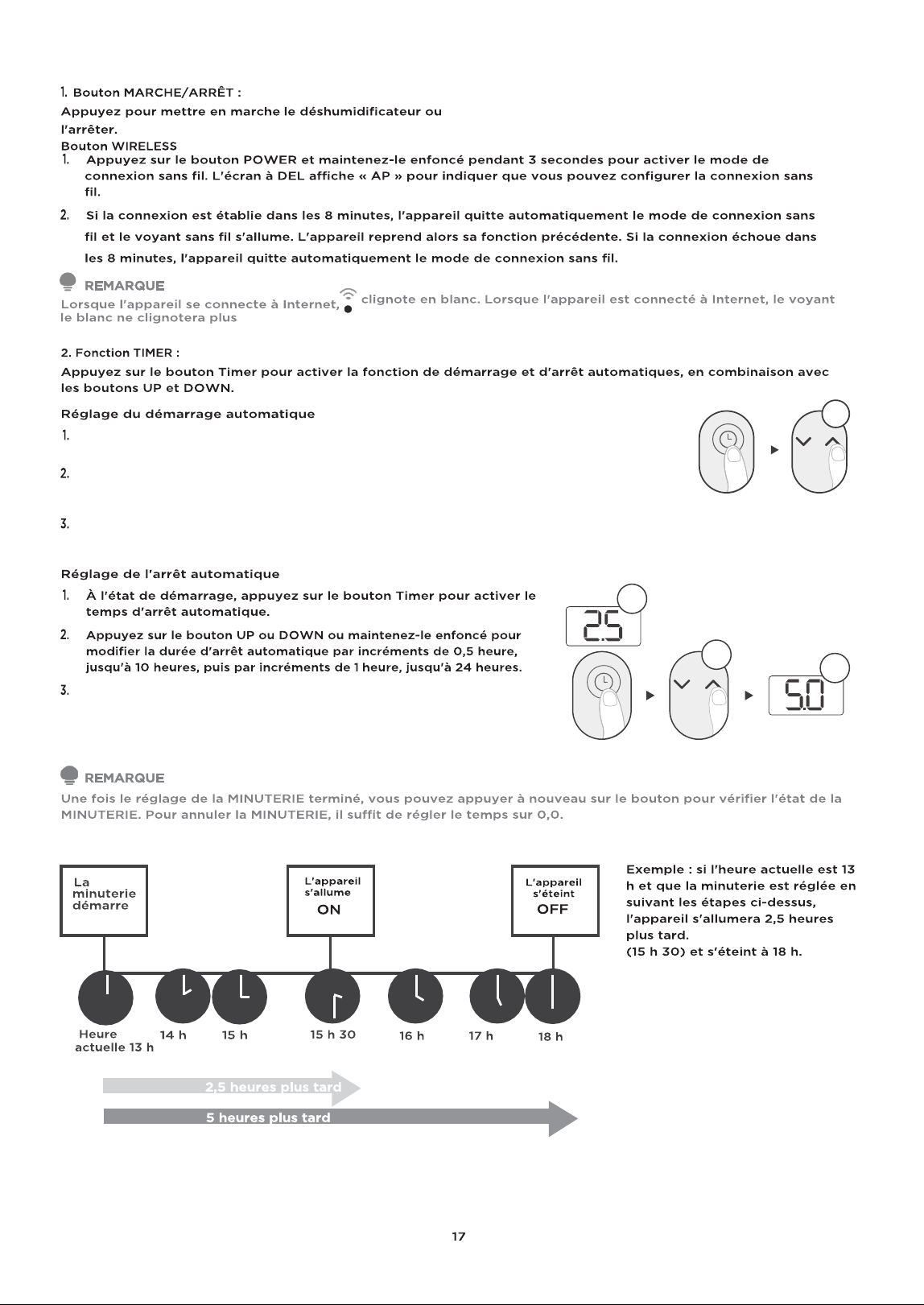
2. TIMER Function:
Press the Timer button to initiate the Auto start and Auto stop function, in conjunction with the UP and
DOWN buttons.
Auto start setting
1. When the unit is off, press the timer button to activate the Auto start time.
2. Press or hold the UP or DOWN button to change the Auto start time by 0.5 hour
increments, up to 10 hours. After the 10th hour, it will be by 1 hour increments, up
to 24 hours.
3. The selected time will register in 5 seconds, after which the system will
automatically revert to displaying the ambient humidity. The control will also count down the remaining
time until the start.
Auto stop setting
1. In the startup state, press the Timer button to active the Auto
stop time.
2. Press or hold the UP or DOWN button to change the Auto stop
time by 0.5 hour increments, up to 10 hours, then at 1 hour
increments, up to 24 hours.
3. The selected time will register in 5 seconds and the system will
automatically revert back to display the ambient humidity. The
control will count down the time remaining until stop.
Once the TIMER setting is complete, you can press the button again to check the TIMER status. To cancel the
TIMER, simply set the time to 0.0.
NOTE
Example: If current time is
1:00PM, and the timer is set
following the steps above,
the unit will turn on 2.5h later
(3:30PM) and turn off at 6:00PM.
x5
5sec
x10
5sec
Current
time 1PM
2:00PM 3:00PM
4PM 5PM
6PM
Timer
starts
Unit turns
ON
Unit turns
OFF
5 hours later
3:30PM
2.5 hours later
1. POWER ON/OFF Button:
Press to turn the dehumidifi er on and off.
WIRELESS Button
1. Press and hold the POWER button for 3 seconds to initiate the Wireless connection mode. The LED
DISPLAY will show ‘AP’ to indicate that you can now set up the wireless connection.
2. If the connection is successful within 8 minutes, the unit will automatically exit Wireless connection mode,
and the Wireless indicator will illuminate. The unit will resume its previous function. If the connection fails
within 8 minutes, the unit will exit Wireless connection mode automatically.
When the unit is connecting to the Internet, the light will fl icker in white. When the unit has connected
to the Internet, the white light will stop fl ickering
NOTE
18
The unit will automatically maintain room
humidity within a comfortable range of 45%
to 55%, depending on the room temperature.
NOTE
The fan speed indicator light illuminates under different
fan speed settings.
NOTE
For some models, the unit will exit Dryer mode
after a maximum of 10 hours of operation.
NOTE
The humidity setting cannot be adjusted
manually in Dryer, Continuous, or Comfort
mode. The set humidity will be displayed
when the mode is selected, and the ambient
humidity will appear 5 seconds later.
NOTE
Humidity can be set from 35% to 85%, with
5% adjustment per press.
NOTE
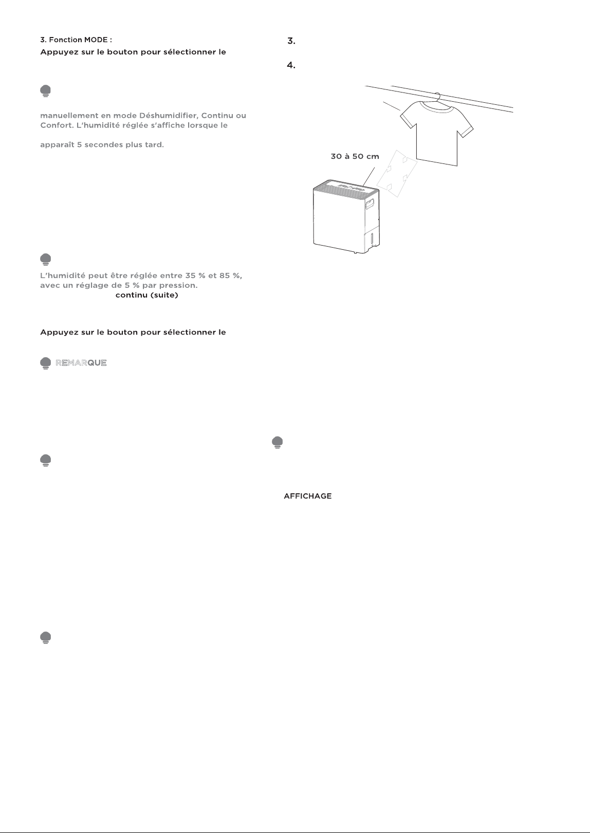
3. MODE Function:
Press the button to select the mode you want,
as shown: Set → Cont. → Dryer → Comfort.
Set Dehumidifying Mode (Set)
Set mode allows you to manually adjust the
desired humidity level between 35% and 85%.
Press the button to select the Dehumidifying
mode, and adjust the desired humidity by
pressing the UP and DOWN buttons.
Continuous Dehumidifying Mode (Cont.)
Press the button to select the Continuous
dehumidifying mode.
Comfort Dehumidifying Mode (Comfort)
Press the button to select the Comfort
Dehumidifying mode.
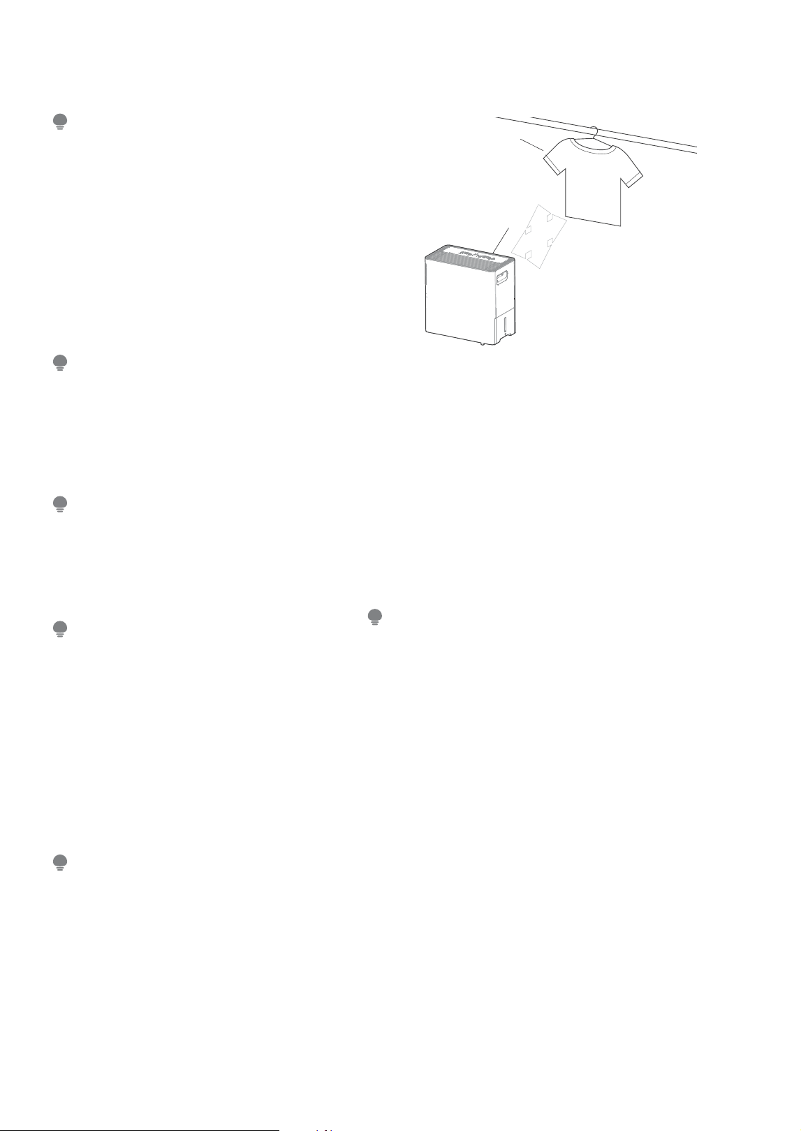
Dryer Mode (Dryer)
In dryer mode, the unit will fi lter out moisture
and blow it back into the room at a warmer
temperature on a higher fan setting.
Press the button to select Dryer mode. In
this mode, the unit will operate in continuous
dehumidifying with high fan speed.
30~50cm
Wet clothes
30~50cm
$LUµRZ
Allow 30~50cm of distance
on the top and right side of
the unit to the wet clothes.
4. UP AND DOWN Buttons:
Humidity Set Control Buttons
The humidity level can be set within a range of 35% RH
(Relative Humidity) to 85% RH (Relative Humidity) in 5%
increments.
TIMER Set Control Buttons
Press the UP and DOWN buttons to set the Auto start and
Auto stop time from 00:00 to 24:00.
5. FAN SPEED Function:
Press the button to select a fan speed in the following
setting: Low → High → Low ...
6. DISPLAY:
The electronic display will show both the ambient humidity and
the set humidity. When the timer function is active, the display
will indicate the set time. In case of an error, the display will
show the corresponding error code.
Error Codes:
ES/EH61 - Evaporator coil temperature sensor error.
Unplug the unit and plug it back in. If the error repeats,
call for service.
AS/EH60 - Room temperature sensor error. Unplug the
unit and plug it back in. If the error repeats, call for service.
P2 - Bucket is full of water or bucket is not in right position.
Empty the bucket and replace it in the right position.
Eb - For the water pump models, the unit will display “Eb” if
the bucket is not in the right position.
EH00 - Indoor EEPROM error. Unplug the unit and plug it
back in. If error repeats, call for service.
1. Close doors and windows while operating
in this mode.
2. For best results, please ring out excess
moisture from the clothes before using the
dryer mode.
Fig. 5
3. Make sure to direct airfl ow at the wet clothes.
4. Clothes that are thick and heavy may not dry as
effectively.
Humidity cannot be adjusted in this mode.
NOTE
19

20
SMART FEATURE SETUP
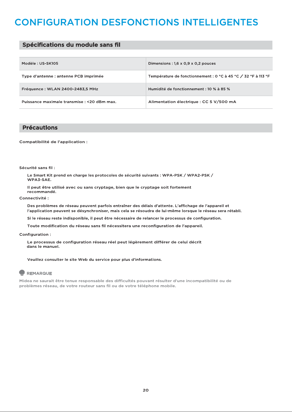
Specifi cation of Wireless Module
Model: US-SK105 Dimensions: 1. 6 x 0.9 x 0.2 (in.)
Antenna Type: Printed PCB Antenna Operation Temperature: 0°C ~ 45°C / 32°F ~ 113°F
Frequency: WLAN 2400-2483.5 MHz Operation Humidity: 10% ~ 85%
Maximum Transmitted Power: <20 dBm Max Power Input: DC 5V/500 mA
Precautions
App Compatibility:
• The app is available for both iOS and Android, however older versions may no longer be compatible.
Please keep the app updated with the latest version. Midea makes no guarantee of compatibility and is not
responsible for issues arising as a consequence thereof.
Wireless Security:
• The Smart Kit supports the following security protocols: WPA-PSK / WPA2-PSK / WPA3-SAE.
• It may be used with or without encryption although encryption is strongly recommended.
Connectivity:
• Network issues may occasionally cause timeouts. The unit display and the app may become unsynchronized
but this will resolve itself when the network is restored.
• Should the network remain unavailable, it might be necessary to run the confi guration process again.
• Change in the wireless network will require reconfi guration of the device.
Confi guration:
• The actual network confi guration process may vary slightly from the manual.
• Please check the service website for more information.
Midea will not be responsible for any problems that could be caused by incompatibility or network issues,
your wireless router and mobile phone.
NOTE
21
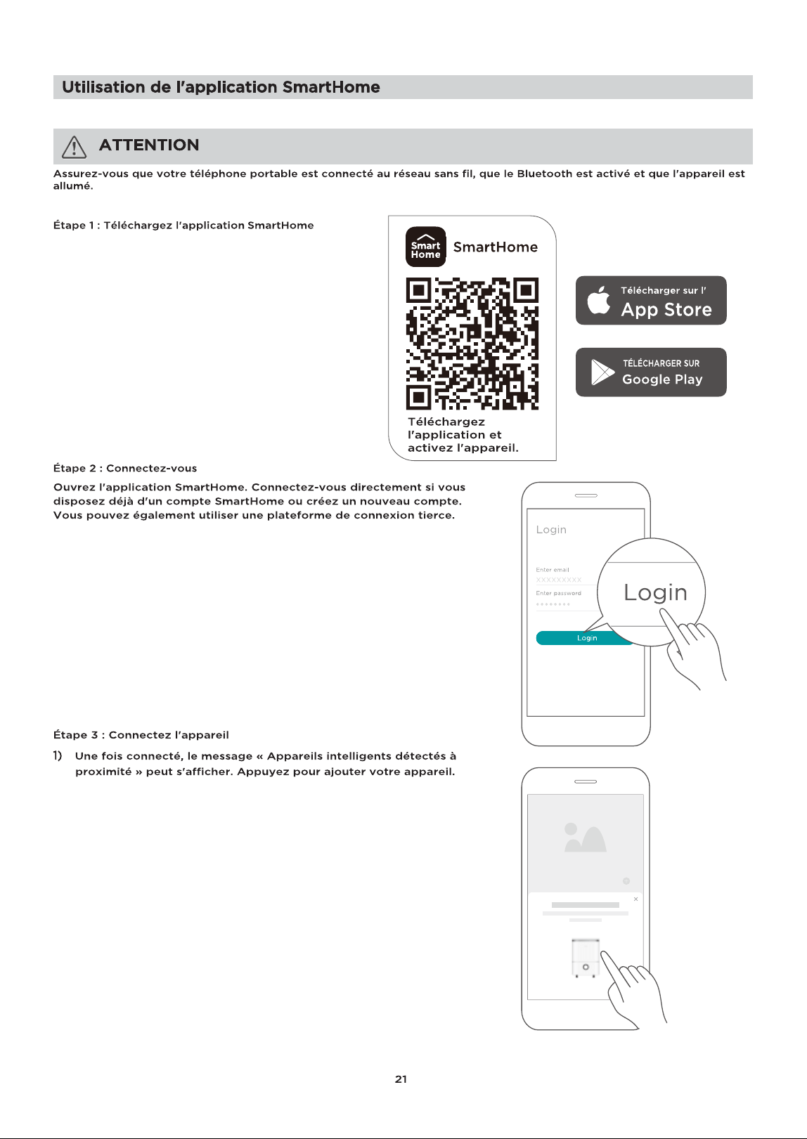
Using the SmartHome App
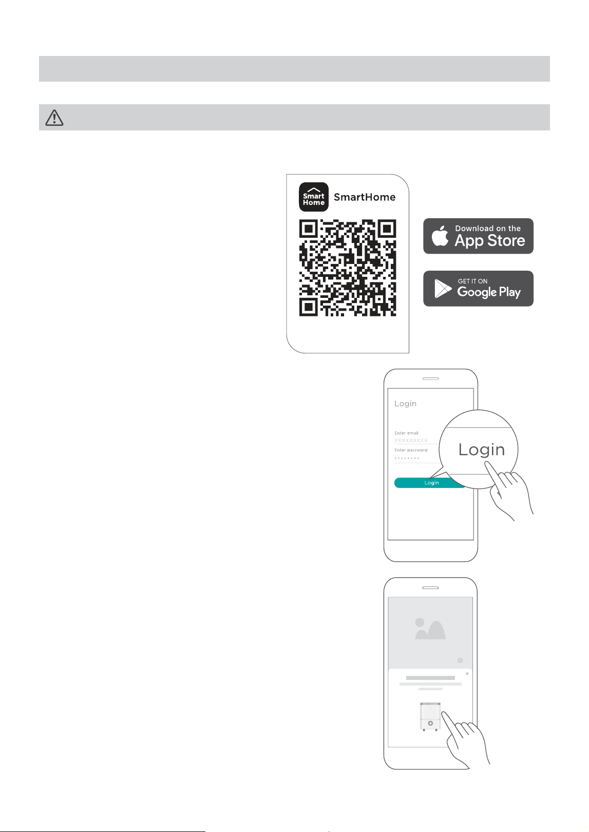
Step 1: Download the SmartHome app
Scan the QR code below to download the
SmartHome app from app store or search for it
directly on the Google Play Store or Apple App
Store.
Step 2: Log in
Open the SmartHome app. Log in directly if you have an existing
SmartHome account or create a new account. Alternatively, you can
also use a 3rd party login platform.
Step 3: Connecting the device
1) When you log in, you may see the message “Smart devices
discovered nearby”. Tap to add your device.
Ensure your mobile phone is connected to the wireless network, Bluetooth is enabled, and the device is powered on.
CAUTION
Download the app
& activate product
22
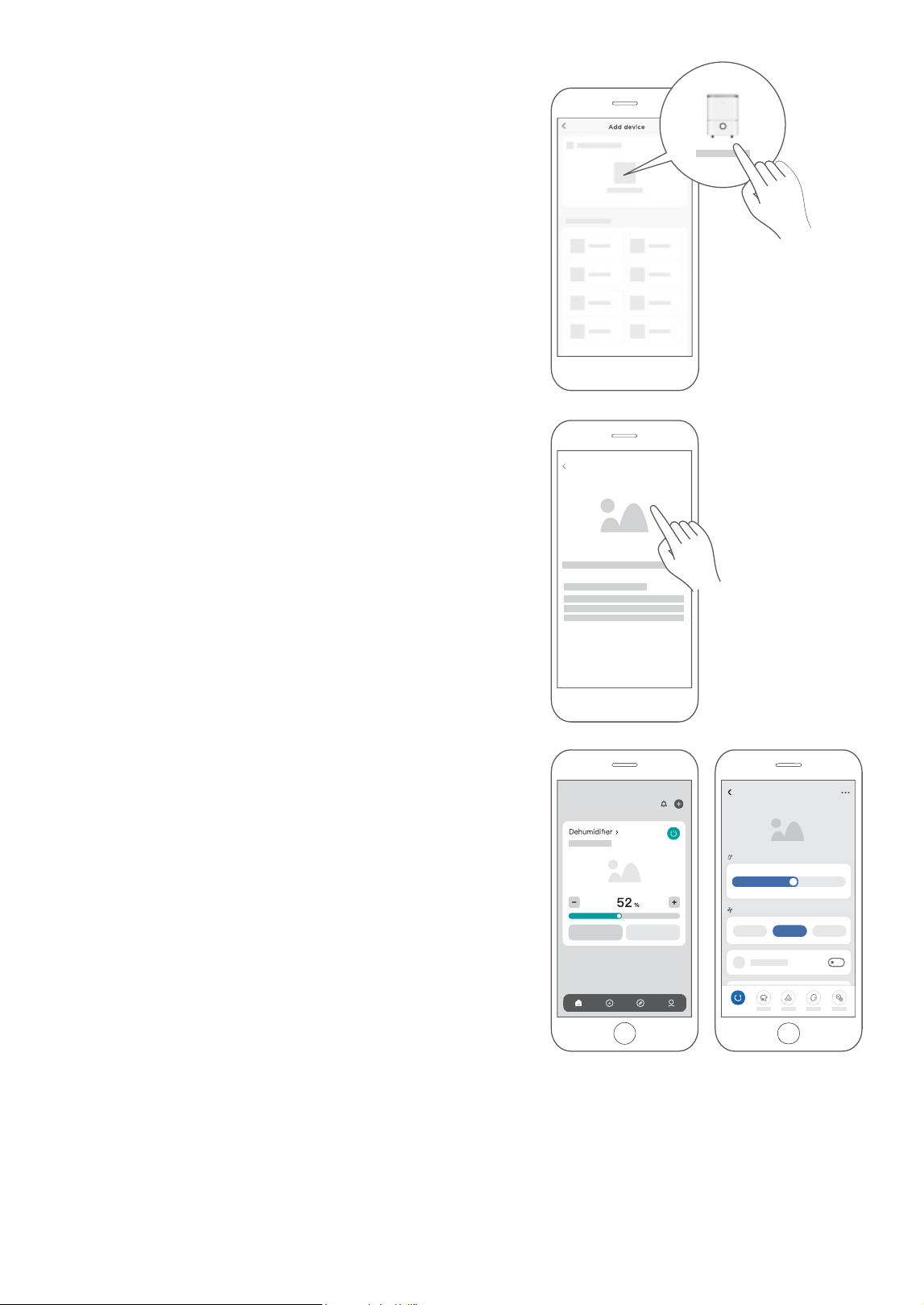
2) If no such message appears, proceed as follows:
Tap on “+” and select your device in the list of nearby
available devices.
If your device is not listed, please add your device manually,
fi rst selecting the device category (i.e. Dehumidifi er).
3) Follow the steps in the app to connect your device to the
wireless network. If your device fails to connect, follow the
additional instructions in the app.
Step 4: Controlling the device
After pairing successfully, a card will be created for the device in
the SmartHome app.
Shortcuts for basic functions will appear on the card such as
changing the humidity or switching the device on or off.
Tapping on the card (as shown on Fig. A), will reveal additional
features and settings.
The actual design may look different from examples due to
app updates.
Fig. A
Dehumidifier
52%
38%
45%
55% 70%
Target Humidity
Low Med High
Fan Speed
Room humidity 52%
Power
SmartHome
Add device

23
Compliance
We, hereby declare that this dehumidifi er is in compliance with the relevant provisions of RE Directive
2014/53/EU. A copy of the full DoC is attached (Europen Union products only).
Wireless module models:
US-SK105:
FCC ID: 2ADQOMDNA21
IC: 12575A-MDNA21
This device complies with Part 15 of the FCC Rules and it contains licence exempt transmitter(s) / receiver(s)
that comply with Innovation, Science and Economic Development Canada’s licence-exempt RSS(s).
Operation is subject to the following two conditions:
(1) This device may not cause harmful interference;
(2) This device must accept any interference, including interference that may cause undesired operation of
the device.
Only operate the device in accordance with the instructions supplied.
Changes or modifi cations to this unit not expressly approved by the party responsible for compliance could
void the user’s authority to operate the equipment.
This device complies with FCC radiation exposure limits set forth for an uncontrolled environment. In order to
avoid the possibility of exceeding the FCC radio frequency exposure limits, human proximity to the antenna
shall not be less than 20cm (8 inches) during normal operation.
This equipment has been tested and found to comply with the limits for a Class B digital device, pursuant to part
15 of the FCC Rules. These limits are designed to provide reasonable protection against harmful interference in a
residential installation. This equipment generates, uses and can radiate radio frequency energy and, if not installed
and used in accordance with the instructions, may cause harmful interference to radio communications. However,
there is no guarantee that interference will not occur in a particular installation. If this equipment does cause
harmful interference to radio or television reception, which can be determined by turning the equipment off and
on, the user is encouraged to try to correct the interference by one or more of the following measures:
• Reorient or relocate the receiving antenna.
• Connect the equipment into an outlet on a circuit different from that to which the receiver is connected.
• Consult the dealer or an experienced radio/TV technician for help.
NOTE

24
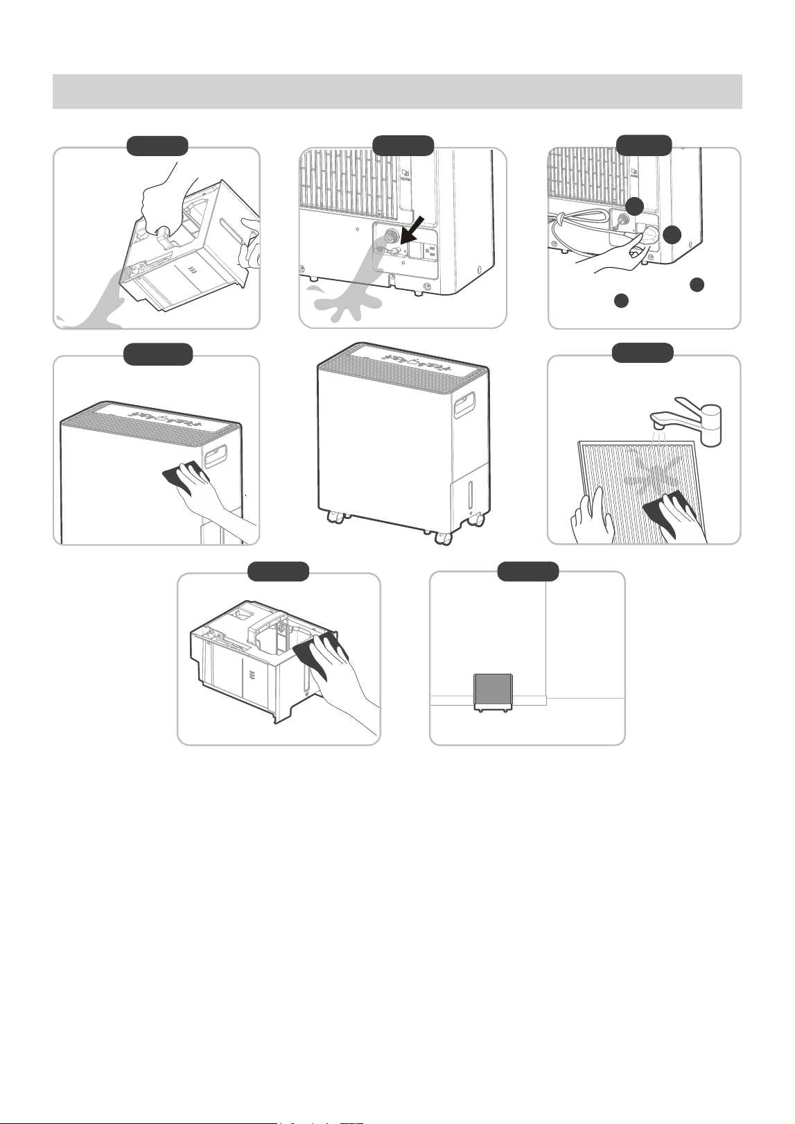
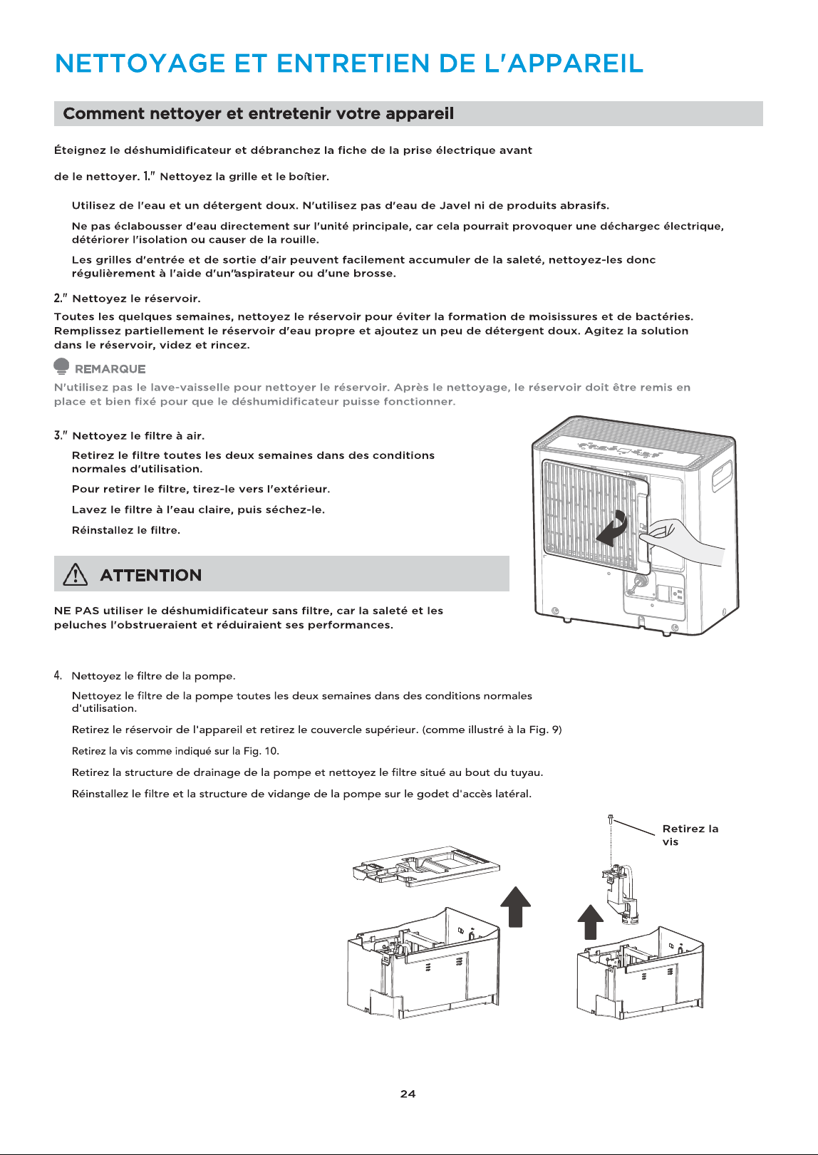
How To Clean & Care For Your Product
CLEANING AND MAINTENANCE
Turn the dehumidifi er off and disconnect the plug from the power source before cleaning.
CAUTION
DO NOT operate the dehumidifi er without the fi lter because dirt and
lint will clog it and reduce performance
3. Clean the air fi lter
• Remove the fi lter every two weeks based on normal operating
conditions.
• To remove the fi lter, pull fi lter outwards.
• Wash the fi lter with clean water then dry.
• Re-install the fi lter.
4. Clean the pump fi lter
• Clean the pump filter every two weeks based on normal operating conditions.
• Take out the water bucket from the unit and remove the bucket top cover. (as shown as Fig. 9)
• Remove the screw as shown as Fig. 10.
• Take out the pump drainage structure and clean the filter at the button of the hose.
• Reinstall the filter and pump drainage structure to the side access bucket.
Do not use a dishwasher to clean the bucket. After cleaning, the bucket must be in place and securely seated
for the dehumidifi er to operate.
NOTE
1. Clean the Grill and Case
• Use water and a mild detergent. Do not use bleach or abrasives.
• Do not splash water directly onto the main unit, as this may result in electrical shock, deteriorate
insulation, or cause rust.
• The air intake and outlet grilles can collect dirt easily, so clean them regularly using a vacuum attachment
or brush.
2. Clean the bucket
Every few weeks, clean the bucket to prevent growth of mold, mildew and bacteria. Partially fill the
bucket with clean water and add a little mild detergent. Swish it around in the bucket, empty and rinse.
Fig. 10Fig. 9
Fig. 8
Remove
the screw
25
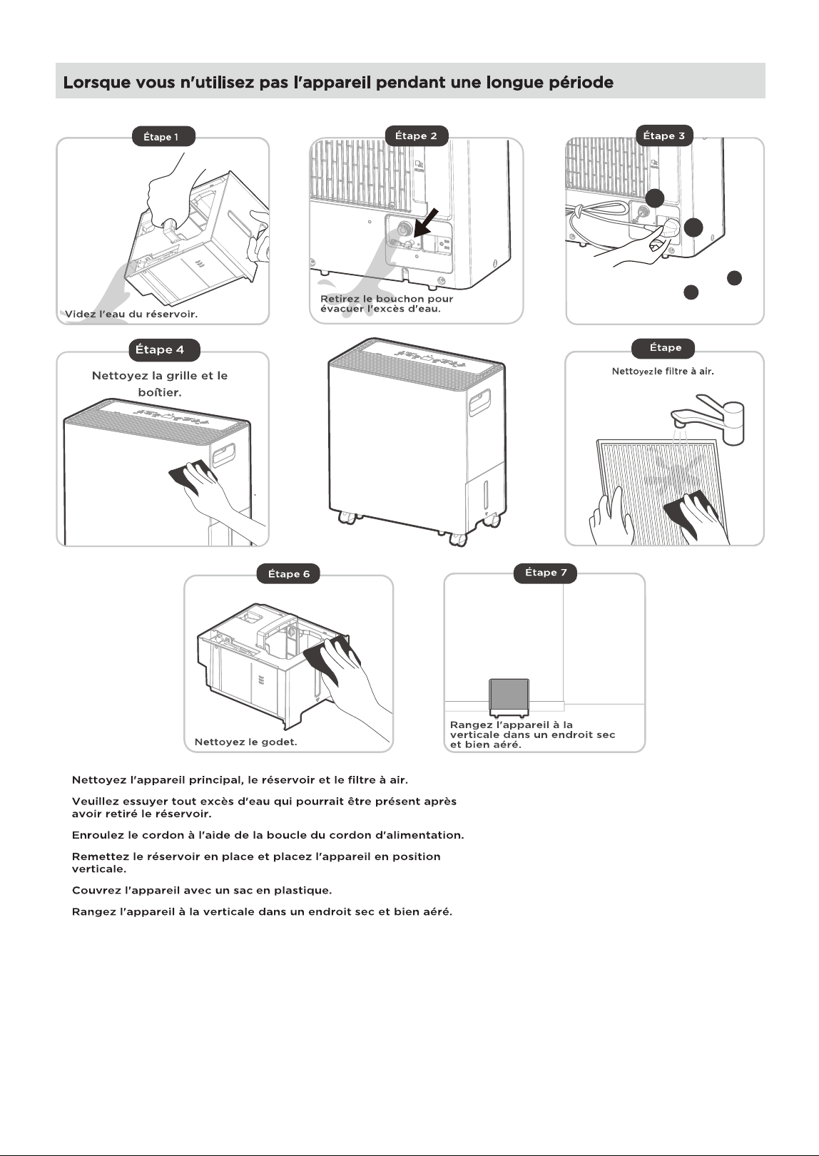
When Not Using The Unit For Long Time Periods
• Clean the main unit, water bucket and air filter.
• Please dry off any excess water that may be present after removing the bucket.
• Wrap the cord with the power cord buckle.
• Properly restore the bucket and place the unit in an upright position.
• Cover the unit with a plastic bag.
• Store the unit upright in a dry, well-ventilated place.
Step 2
Remove water plug to drain
any excess water.
Step 3
Re-insert the water plug and
insert plug into the the back
of the unit to keep them in place.
Step 1
Remove water from the bucket.
Clean the grille and case.
Step 4
Clean the bucket.
Step 6
Store the unit upright in a dry,
well-ventilated place.
Step 7
&OHDQWKHDLU´OWHU
.
Step 5
1
2
1
2
26
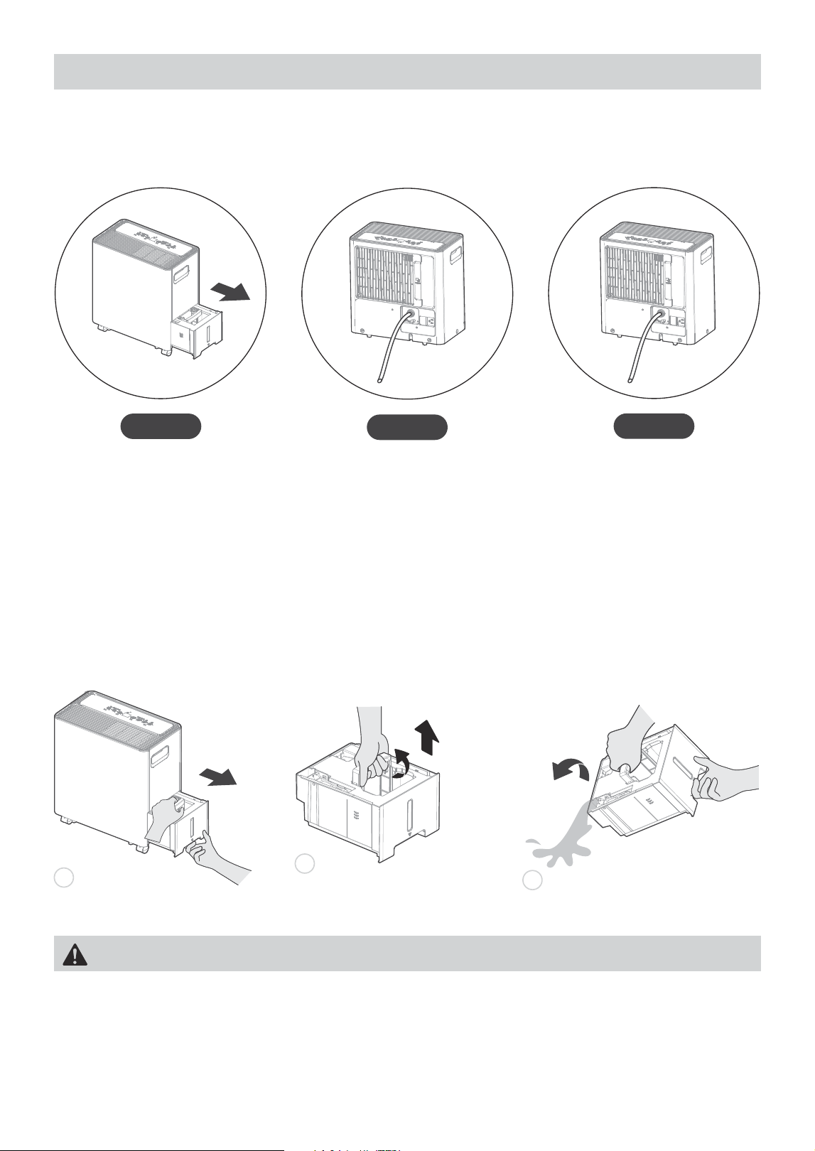
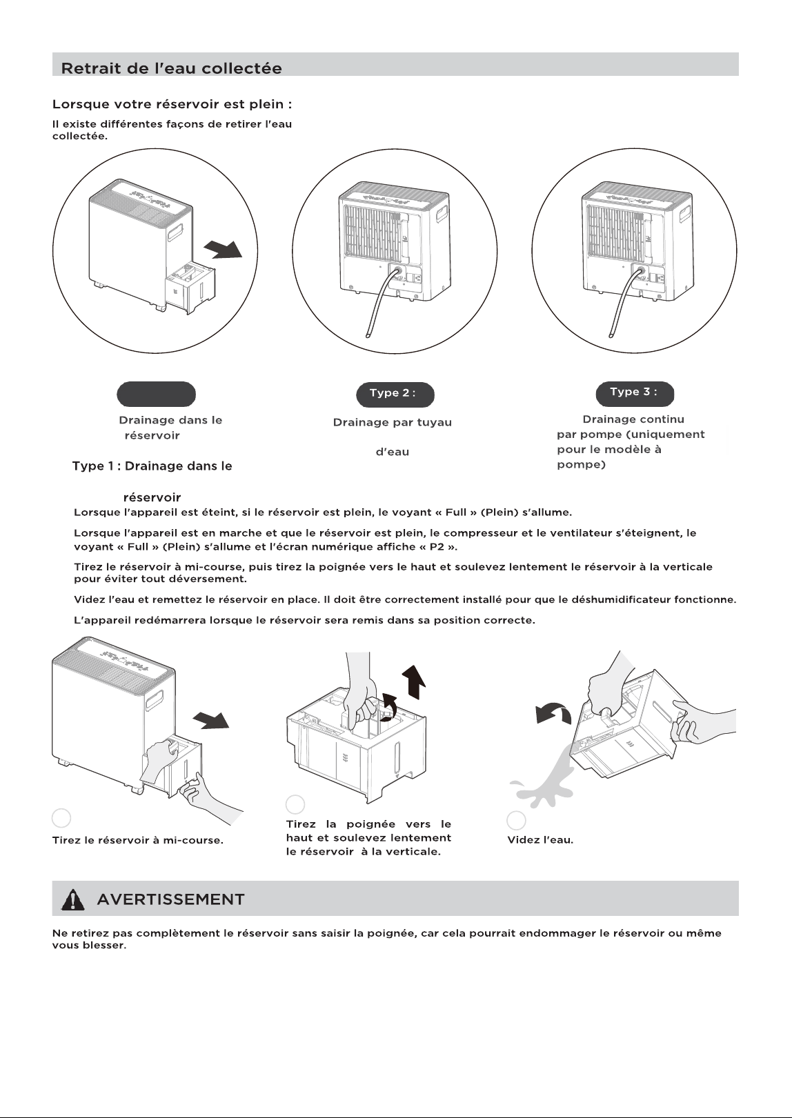
Removing Collected Water
When Your Bucket Is Full
Type 1: Bucket Drainage
There are different ways to remove collected water.
• When the unit is off, if the bucket is full, the Full Indicator light will turn on.
• When the unit is on and the bucket is full, the compressor and fan will turn off, the Full indicator light
will activate, and the digital display will show “P2.”
• Pull the bucket out halfway, then pull up the handle and lift the bucket slowly vertically to prevent spillage.
• Dump the water and replace the bucket. The bucket must be correctly installed for the dehumidi er to operate.
• The unit will re-start when the bucket is restored in its correct position.
1
Pull the bucket out halfway.
Do not pull out the whole bucket without grabbing the handle, or it may cause damage to the bucket or
even injure you.
WARNING
2
Pull up the handle and lift
the bucket slowly vertically.
3
Pour the water out.
Bucket drainage
Type 1:
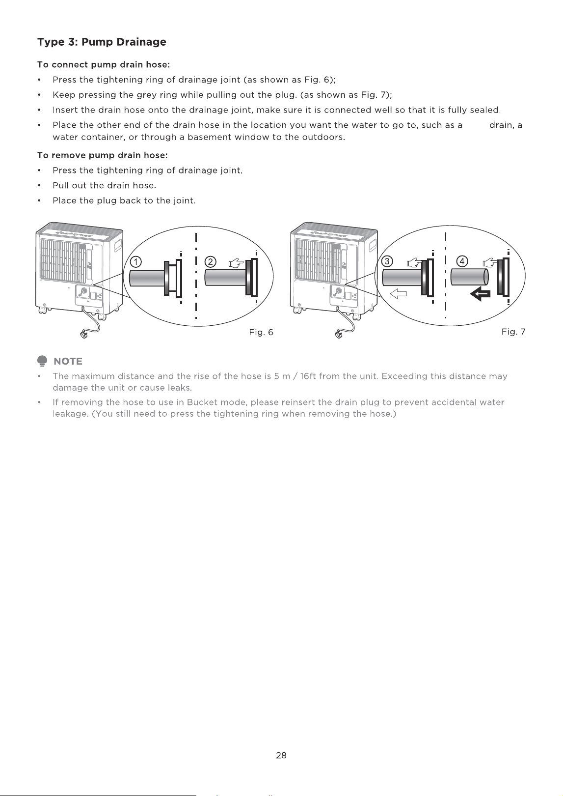
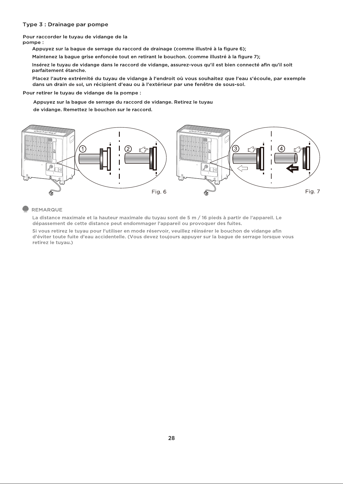
Type 3:
Pump drainage
(only for pump model)
Type 2:
Water hose drainage
(continuous)
27
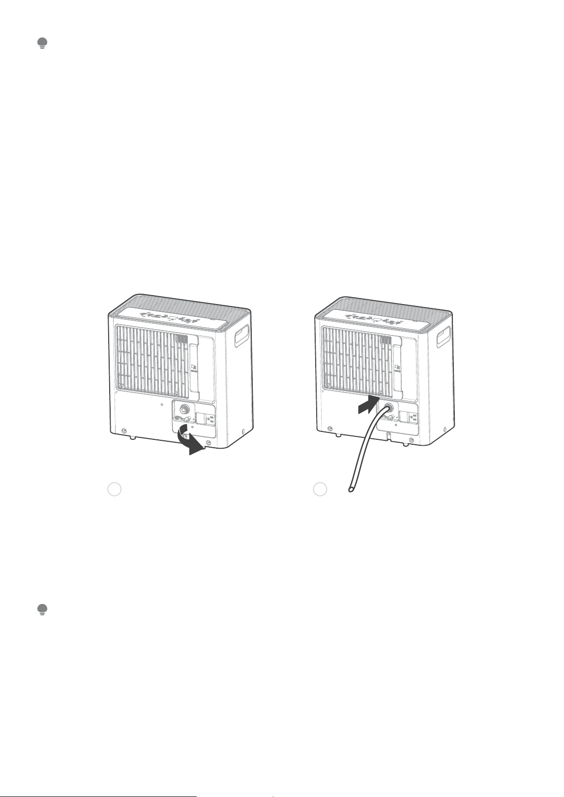
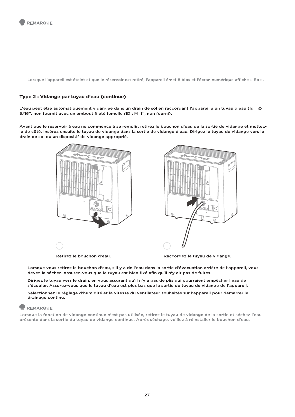
Type 2: Water Hose Drainage (continuous)
• When you remove the bucket, do not touch any parts inside of the unit. Doing so may damage the product.
Be sure to push the bucket gently all the way into the unit. Banging the bucket against anything or failing
to push it in securely may cause the unit not to operate.
• If the pump hose becomes disconnected when you remove the bucket, you must reinstall the pump hose
properly to the unit before replacing the bucket .
• When you remove the bucket, if there is some water in the unit you must dry it.
• When the unit is on and the bucket is removed, the compressor and fan will turn off, the unit will beep 8
times, and the digital display will show “Eb”.
• When the unit is off and the bucket is removed, the unit will beep 8 times, and the digital display will show “Eb”.
NOTE
Water can be automatically emptied into a fl oor drain by attaching the unit with a water hose (ld Ø 5/16”,
not included) with a female threaded end (ID: M=1”, not included).
Before the water bucket begins fi lling, remove the water plug from the drain outlet and set aside. Then, insert the
drain hose through the water drain outlet. Lead the drain hose to the fl oor drain or a suitable drainage facility.
When the continuous draining feature is not being used, remove the drain hose from the outlet, and dry the
water in the continuous drain hose outlet. After drying, make sure to reinstall the water plug.
NOTE
1
Remove the water plug.
2
Connect the drain hose.
• When you remove the water plug, if there is any water in the back drain outlet of the unit you must dry it.
Make sure the hose is secure so there are no leaks.
• Direct the hose toward the drain, making sure that there are no kinks that will stop the water fl owing. Make
sure the water hose is lower than the drain hose outlet of the unit.
• Select the desired humidity setting and fan speed on the unit for continuous draining to start.
floor

29
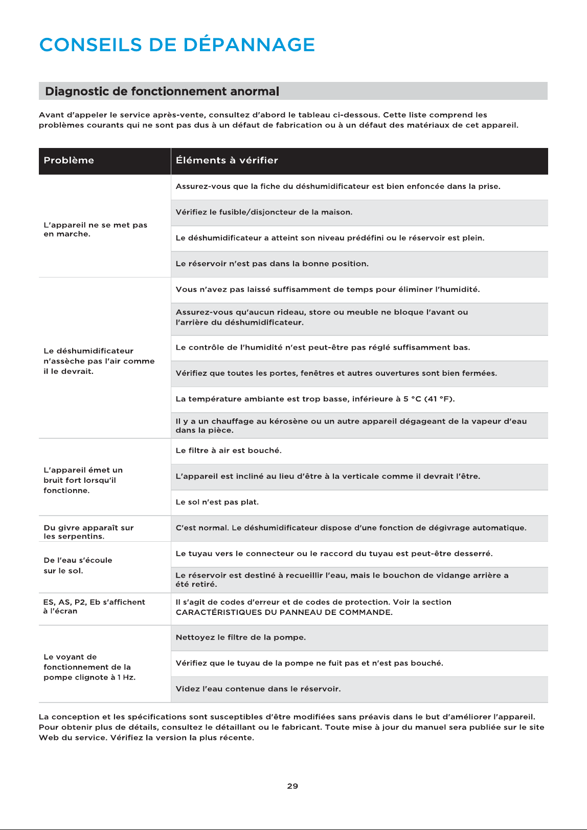
TROUBLESHOOTING TIPS
Problem What to check
Unit does not start
Make sure the dehumidifi ers plug is pushed completely into the outlet.
Check the house fuse/circuit breaker box.
Dehumidifi er has reached its preset level or bucket is full.
Water bucket is not in the proper position.
Dehumidifi er does not dry
the air as it should
Did not allow enough time to remove the moisture
Make sure there are no curtains, blinds or furniture blocking the front or back
of the dehumidifi er.
The humidity control may not be set low enough.
Check that all doors, windows and other openings are securely closed.
Room temperature is too low, below 5°C (41°F).
There is a kerosene heater or something giving off water vapor in the room.
The unit makes a loud
noise when operating
The air fi lter is clogged.
The unit is tilted instead of upright as it should be.
The fl oor surface is not level.
Frost appears on the coils This is normal. The dehumidifi er has an Auto defrost feature.
Water is leaking onto the
fl oor
Hose to connector or hose connection may be loose.
Intended to use the bucket to collect water, but the back drain plug is removed.
ES, AS, P2, Eb appear on
display
These are error codes and protection codes. See the CONTROL PANEL
FEATURES section.
The pump operation on
light blinks at 1 Hz
Clean the fi lter of the pump.
Check the pump hose does not leak or block.
Empty the water in the bucket.
Before calling for service, review the chart below fi rst. This list includes common occurrences that are not the
result of defective workmanship or materials in this unit.
The design and specifi cations are subject to change without prior notice for product improvement.
Consult with the sales agency or manufacturer for details. Any updates to the manual will be uploaded to the
service website, please check for the latest version.
Malfunction Diagnosis

30
WARRANTY
Dehumidifi er Limited Warranty
Your product is protected by this Limited Warranty:
Warranty service must be obtained from Midea Consumer Services or an authorized Midea servicer.
Warranty
Midea, through its authorized servicers will:
• Pay all costs for reparing or replacing parts of this appliance which prove to be defective in materials or
workmanship.
Consumer will be responsible for:
• Diagnostics, removal, transportation and reinstallation cost required because of service.
• Costs of service calls that are a result of items listed under NORMAL RESPONSABILITIES OF THE CONSUMER**
Midea replacement parts shall be used and will be warranted only for the original warranty.
NORMAL RESPONSABILITIES OF THE CONSUMER**
This warranty applies only to products in ordinary household use, and the consumer is responsible for the items
listed below:
1. Proper use of the appliance in accordance with instructions provided with the product.
2. Routine maintenance and cleaning is necessary to keep the good working condition.
3. Proper installation by an authorized service professional in accordance with instructions provided with the appliance and
in accordance with all local plumbing, electrical and/or gas codes.
4. Proper connection to a grouded power supply of suffi cient voltage, replacement of blown fuses, repair of loosen
connections or defects in house wiring.
5. Expenses for making the appliance accessible for servicing.
6. Damages to fi nish after intallation.
EXCLUSIONS
This warranty does not cover the following:
1) Failure caused by damage to the unit while in your possesion (other than damage caused by defect or
malfunction), by its improper installation, or by unreasonable use of the unit, including without limitation, failure
to provide reasonable and necessary maintenance or to follow the written installation and Operating Instructions.
2) Damages caused by serviced performed by persons other than those authorized by Midea customer service; or
external causes such as abuse, misuse, inadequate power supply or acts of God.
3) If the unit is put to commercial, business, rental, or other use or application other than for consumer use, Midea
makes no warranties, express or implied, including but not limited to, any implied warranty of merchantability or
fi tness for use or purpose.
4) Products without original serial numbers or products that have serial numbers which have been altered or cannot
be readily determined.
NOTICE: Some states do not allow the exclusions or limitation of incidental or consequential damages. So this
limitation or exclusion may not apply to you.
IF SERVICE IS NEEDED
Keep the bill of sale, delivery slip, or some other appropriate payment record.
The date on the bill establishes the warranty period, should service be required.
If service is performed, its your best interest to obtain and keep all receipts.
This written warranty gives you specifi c legal rights. You may also have other rights that vary from state to state.
Service under this warranty must be obtained by following these steps, in order:
1)Contact Midea Consumer Services or an authorized Midea services at 1-888-365-2230.
2)If there is a question as to where to obtain service, contact our consumer relations Departament.
• One Year Limited Warranty from the date of delivery or the purchase date, whichever is later.
• The date of delivery establishes the warranty period, should service be required.


2026
MAD
MANUEL D'UTILISATION
Avertissements : avant d'utiliser cet appareil, veuillez lire attentivement ce manuel et le conserver pour
référence ultérieure. La conception et les spécifications sont susceptibles d'être modifiées sans préavis
dans le but d'améliorer l'appareil. Pour obtenir plus de détails, consultez votre détaillant ou le fabricant.
Le schéma ci-dessus est fourni à titre indicatif. Veuillez vous référer à l'apparence de l'appareil réel.
MAD50S1OWWCM
Déshumidificateur

2
TABLE DES MATIÈRES
Merci d'avoir choisi Midea!
Avant d'utiliser votre nouvel appareil Midea, veuillez lire attentivement ce manuel afin de garantir un
fonctionnement sûr et efficace de ses caractéristiques et ses fonctions.
ATTENTION
SOMMAIRE ..............................................................................................................2
MESURES DE SÉCURITÉ.........................................................................................3
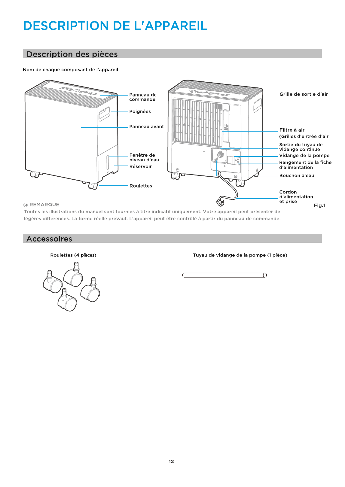
DESCRIPTION DE L'APPAREIL ............................................................................12
INSTALLATION DE L'APPAREIL ..........................................................................13
CARACTÉRISTIQUES DE L'APPAREIL..................................................................16
CONFIGURATION DES FONCTIONS INTELLIGENTES .......................................20
NETTOYAGE ET ENTRETIEN DE L'APPAREIL.....................................................24
CONSEILS DE DÉPANNAGE...................................................................................29
GARANTIE................................................................................................................30
Ce manuel contient des conseils précieux pour l'utilisation et l'entretien corrects de votre déshu-
midificateur. Avec un peu d'entretien préventif, vous pouvez gagner du temps et de l'argent tout
au long de la durée utile de l'appareil. La section consacrée au dépannage traite des problèmes
courants, vous permettant de résoudre rapidement la plupart des problèmes avant de faire appel
à un service professionnel. Bien que ces instructions couvrent de nombreux scénarios, il est
essentiel de faire preuve de bon sens et de respecter les consignes de sécurité lors de l'installa-
tion, du fonctionnement et de l'entretien de l'appareil.
• Pour obtenir de l'aide, veuillez appeler le centre de service au 1-888-365-2230.
• Cet appareil n'est pas destiné à être utilisé par des personnes (y compris des enfants) ayant des capacités
physiques, sensorielles ou intellectuelles réduites ou manquant d'expérience et de connaissances, à moins
qu'elles ne soient surveillées ou aient reçu des instructions concernant l'utilisation de l'appareil par une
personne responsable de leur sécurité.
• Les enfants doivent être surveillés afin de s'assurer qu'ils ne jouent pas avec l'appareil.
• L'appareil doit être installé conformément aux réglementations nationales en matière de câblage électrique.
•
•
•
•
•
•
•
•
•
•
•
•
•
•
•
•
•
•
•
•
•
•
•
•
•
•
•
•
•
•
•
•
•
•
•
•
•
•
•
•
•
•
•
•
•
•
•
•
•
•
A2L
•
•
•
•
•
•
•
•
•
•
•
•
•
•
AVERTISSEMENT ( l'utilisation du réfrigérant R32)

-
-
-
-
-
-
INSTALLATION
Vue de face Vue
dessus
Fig. 2
•
•
•
•
•
•
•
•
•
•
•
•
•
•
40 cm
/
15,7
pouces ou
plus
20 cm / 7,8
pouces ou
plus
40 cm
/
15,7
pouces ou
plus
40 cm / 15,7
pouces ou
plus
20 cm / 7,8
pouces ou
plus
Températur
Max.
5 °C/41 °F 32 °C/90 °F
Min.
Humidité de fonctionnement
Max.
30 %
(HR)
80 %
(HR)
3 min
•
•
•
•
•
•
•
•
Coussin en
mousse
•
•
•
•
2 31
4 6
5
Coussin en
mousse
Coussin en mousse
Inclinez l'appareil sur le côté
et maintenez-le d'une main,
puis insérez complètement
les deux roulettes.
16
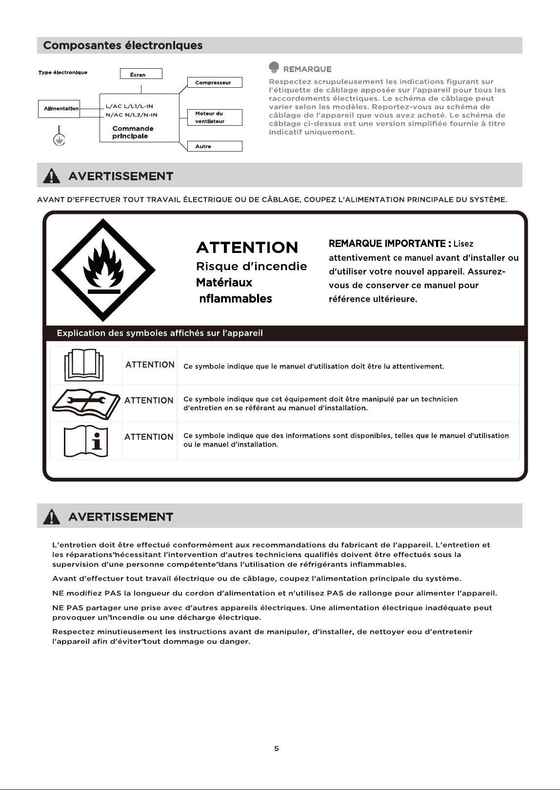
Caractéristiques du panneau de commande
CARACTÉRISTIQUES DE L'APPAREIL
Affichage des opérations
REMARQUE
Les panneaux de commande suivants sont fournis à titre indicatif uniquement. Le panneau de commande de l'appareil que vous
avez acheté peut varier légèrement en fonction du modèle. Certains voyants ou boutons peuvent ne pas être présents. La forme
physique générale de l'appareil restera la même.
Description
1
MARCHE
/
ARRÊT
•
Appuyez pour mettre l'appareil en marche ou l'arrêter.
•
Appuyez pendant 3 secondes pour activer le mode de connexion sans
fil.
2
Bouton
TIMER
•
Appuyez pour activer/désactiver la fonction de démarrage/arrêt
automatique de l'appareil.
3
Bouton
Mode
•
Appuyez pour choisir le mode de fonctionnement dans l'ordre suivant :
Réglage → Cont. → Déshumidifier → Confort
4
Boutons UP / DOWN
•
Appuyez pour régler le taux d'humidité et la minuterie.
5
Bouton
FAN
6
Écran à DEL
•
Affiche l'humidité ambiante et l'humidité réglée, l'heure réglée
(lorsque la fonction minuterie est utilisée) et les codes d'erreur.
7
Bouton
PUMP
•
Appuyez pour activer la fonction de pompe intégrée.
•
Appuyez sur cette touche pour sélectionner la vitesse du ventilateur en
deux étapes : élevée et faible.
•
Appuyez sur cette touche et maintenez-la enfoncée pendant 3
secondes pour désactiver le rappel de nettoyage du filtre.
32 1764 4 5
Minuterie
Timer
Déshumidifier
Set
Cont.
Cont.
Plus sec
Dryer
Comfort
Confort
Full
Plein
Faible Élevée Filtre Pompe
Low High Filter Pump
Reset filter (3s)
Connect (5s)
Réinitialiser le filtre (3s)
Marche/Arrêt (5s)
Reset filter (3s)
Réinitialiser le filtre (3s)
Connect (5s)
Marche/Arrêt (5s)
Lorsque l'appareil est éteint, appuyez sur le bouton de la minuterie pour activer
l'heure de démarrage
Appuyez sur le bouton UP ou DOWN ou maintenez-le enfoncé pour modifier
l'heure de démarrage automatique par incréments de 0,5 heure, jusqu'à 10 heures.
Après la 10e heure, les incréments seront de 1 heure, jusqu'à 24 heures.
L'heure sélectionnée s'enregistre en 5 secondes, après quoi le système revient
automatiquement à l'affichage de l'humidité ambiante. La commande effectuera
également un compte à rebours du temps restant jusqu'au démarrage.
Le temps sélectionné s'affichera dans 5 secondes, puis le
système reviendra automatiquement à l'affichage de
l'humidité ambiante. La commande effectuera un compte
à rebours du temps restant jusqu'à l'arrêt.
x5
5sec
x10
5sec
30~50cm
18
mode souhaité, comme indiqué : Réglage →
Cont. →Déshumidifier → Confort.
REMARQUE
Veillez à diriger le flux d'air vers les vêtements
humides.
Les vêtements épais et lourds peuvent ne pas
sécher aussi
efficacement.
Le réglage de l'humidité ne peut pas être mpodifié
mode est sélectionné, et l'humidité ambiante
Mode Déshumidifier (Set)
Le mode Réglage vous permet de régler
manuellement le taux d'humidité souhaité entre 35
% et 85 %.
Appuyez sur le bouton pour sélectionner le
mode Déshumidifier, puis réglez le taux
d'humidité souhaité à l'aide des boutons HAUT et
BAS.
REMARQUE
4.Boutons UP et DOWN : boutons de contrôle du
réglage de l'humidité
Fig. 5
Mode
Déshumidifier en
mode Déshumidifier en continu.
REMAR E
L'humidité ne peut pas être réglée dans ce
mode.
Mode Déshumidifier en continu (suite)
Appuyez sur le bouton pour sélectionner le
mode Déshumidifier en continu.
REMARQUE
L'appareil maintiendra automatiquement
l'humidité de la pièce dans une plage
confortable comprise entre 45 % et 55 %, en
fonction de la température ambiante.
Mode Plus sec (Dryer)
En mode Plus sec, l'appareil filtre l'humidité et
la renvoie dans la pièce à une température plus
élevée avec un réglage plus élevé du
ventilateur.
Appuyez sur le bouton pour sélectionner le
mode Plus sec. Dans ce mode, l'appareil
fonctionnera en déshumidification continue
avec une vitesse de ventilation élevée.
REMARQUE
Sur certains modèles, l'appareil quitte le
mode Plus sec après 10 heures de
fonctionnement maximum.
1.
Fermez les portes et les fenêtres lorsque
l'appareil"fonctionne dans ce mode.
2.
Pour obtenir de meilleurs résultats, veuillez
essorer"l'excès d'humidité des vêtements
avant d'utiliser le"mode Plus sec.
Le taux d'humidité peut être réglé dans une plage de 35 % HR.
(Humidité relative) à 85 % HR (Humidité relative) par
incréments de 5 %.
Boutons de commande de réglage de la minuterie
Appuyez sur les boutons UP et DOWN pour régler l'heure de
démarrage et d'arrêt automatiques de 00:00 à 24:00.
5.
Fonction VITESSE DU VENTILATEUR :
Appuyez sur le bouton pour sélectionner une vitesse de
ventilation parmi les réglages suivants : Faible → Élevée →
Faible ...
REMARQUE
Le voyant de vitesse du ventilateur s'allume selon les différents
réglages de vitesse du ventilateur.
6.
L'écran affiche à la fois l'humidité ambiante et l'humidité
réglée. Lorsque la fonction minuterie est activée, l'écran
indique l'heure réglée. En cas d'erreur, l'écran affiche le
code d'erreur correspondant.
Codes d'erreur :
ES/EH61 - Erreur du capteur de température du serpentin de
l'évaporateur. Débranchez l'appareil et rebranchez-le. Si l'erreur
persiste, appelez le service après-vente.
AS/EH60 - Erreur du capteur de température ambiante.
Débranchez l'appareil et rebranchez-le. Si l'erreur persiste,
appelez le service après-vente.
P2 - Le réservoir est plein d'eau ou n'est pas dans la bonne
position. Videz le réservoir et replacez-le dans la bonne position.
Eb - Pour les modèles à pompe à eau, l'appareil affiche « Eb » si le
réservoir n'est pas dans la bonne position.
EH00 - Erreur EEPROM intérieure. Débranchez l'appareil et
rebranchez-le. Si l'erreur persiste, appelez le service après-vente.
Vêtements
humides
Flux d'air
Laissez un espace entre 30 et
50 cm entre le haut et le côté
droit de l'appareil et les
vêtements mouillés.
7.
Fonc�on POMPE :
Appuyez sur le bouton
« P » (
Pompe
)
pour ac�ver la fonc�on de
pompe intégrée. Le voyant « Pump Mode » (Mode pompe) s'allume.
Lorsque vous u�lisez ce�e fonc�on, l'appareil pompe
automa�quement l'eau jusqu'à ce que le
soit vide. La
pompe s'arrête automa�quement une fois que le
est vide.
REMARQUES
Le tuyau de vidange de la pompe doit être correctement raccordé
pour ce mode.
Si les voyants de la pompe et du
plein clignotent
simultanément après avoir appuyé sur le bouton « Pump », le
tuyau de vidange est peut-être mal installé.
la page 28
pour les instruc�ons d'installa�on.
Assurez-vous que le tuyau de vidange est orienté dans la direc�on où
vous souhaitez évacuer l'eau.
FONCTION DE VÉRIFICATION DU FILTRE
L'appareil enregistre automa�quement la durée d'u�lisa�on du
moteur du ven�lateur. Une fois que la durée de fonc�onnement
cumulée a�eint 250 heures, le voyant de vérifica�on du filtre s'allume
pour vous indiquer qu'il est temps de ne�oyer le filtre. Après avoir
ne�oyé et réinséré le filtre, appuyez sur le bouton FAN
(
éini�alisa�on du filtre) et maintenez-le enfoncé pendant 3 secondes
pour éteindre le voyant. Ce�e opéra�on se répète toutes les 250
heures d'u�lisa�on. Voir page 24 pour le ne�oyage du filtre.
REDÉMARRAGE AUTOMATIQUE
Si l'appareil s'éteint de manière ina�endue en raison d'une
coupure de courant, il redémarrera automa�quement avec les
derniers réglages lorsque le courant sera rétabli.
ARRÊT AUTOMATIQUE
Le déshumidificateur s'arrête lorsque le est plein, ou lorsque
le
est re�ré ou n'est pas replacé dans la bonne posi�on. Sur
certains modèles, le moteur du ven�lateur con�nue de fonc�onner
pendant 30 secondes.
Lorsque le voyant « Full » (
lein) s'allume, et
réinstalle
correctement.
A�endez ensuite 3 minutes avant de reprendre le fonc�onnement, car
l'appareil ne peut pas redémarrer dans les 3 premières minutes. Ce�e
mesure vise à protéger l'appareil.
Le fonc�onnement redémarrera automa�quement après 3 minutes.
Autres
fonc�onnalités
•
•
•
•
•
•
•
•
L'application est disponible pour iOS et Android, mais les anciennes versions peuvent ne plus être compatibles.
Veuillez mettre à jour l'application avec la dernière version. Midea ne garantit pas la compatibilité et n'est pas
responsable des difficultés qui pourraient en découler.
Balayez le code QR ci-dessous pour télécharger
l'application SmartHome depuis l'App Store ou
recherchez-la directement sur Google Play Store
ou Apple App Store.
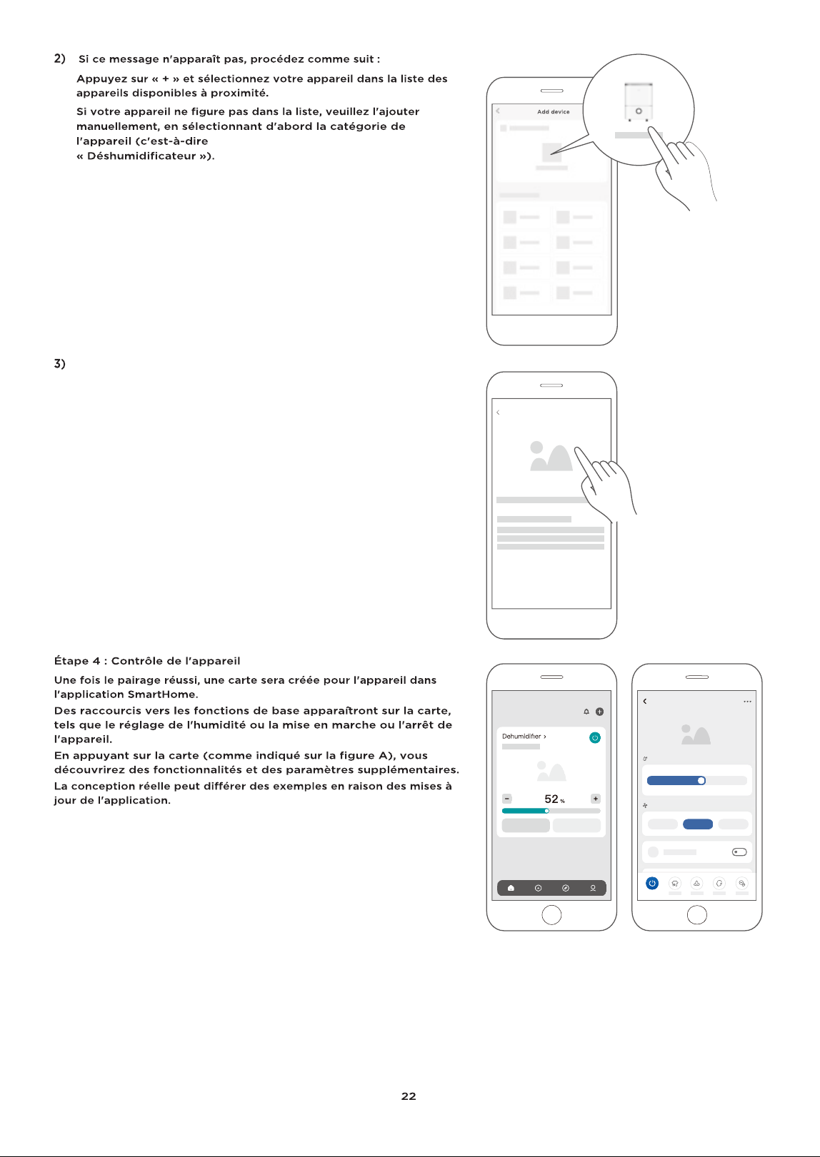
Fig. A
Dehumidifier
52%
38%
45%
55% 70%
Target Humidity
Low Med High
Fan Speed
Room humidity 52%
Power
SmartHome
Add device
Suivez les étapes indiquées dans l'application pour connecter votre
appareil au réseau sans fil. Si votre appareil ne parvient pas à se
connecter, suivez les instructions supplémentaires fournies
dans l'application.
Step 4: Controlling the device
•
•
•
•
•
•
•
•
•
•
•
•
•
•
•
Fig. 10Fig. 9
Fig. 8
1
2
1
2
25
•
•
•
•
•
•
Réinsérez le bouchon d'eau et
insérez le bouchon 2à
l'arrière de l'appareil pour maintenir
en place.
26
Type 1 :
•
•
•
•
•
1
2
3
•
•
•
•
•
≥
•
•
•
1 2
Si le tuyau de la pompe se déconnecte lorsque vous retirez le réservoir, vous devez le réinstaller correctement sur
l'appareil avant de replacer le réservoir.
Lorsque vous retirez le réservoir, s'il reste de l'eau dans l'appareil, vous devez le sécher.
Lorsque l'appareil est en marche et que le réservoir est retiré, le compresseur et le ventilateur s'éteignent,
l'appareil émet 8 bips et l'écran numérique affiche « Eb ».
Lorsque vous retirez le réservoir, ne touchez aucune pièce à l'intérieur de l'appareil. Cela pourrait endommager
l'appareil. Veillez à enfoncer doucement le réservoir à fond dans l'appareil. Si vous cognez le réservoir contre
quoi que ce soit ou si vous ne l'enfoncez pas correctement, l'appareil risque de ne pas fonctionner.
•
•
•
•
•


2026
16122000A83490