user manual
Cyclo Directional IP65
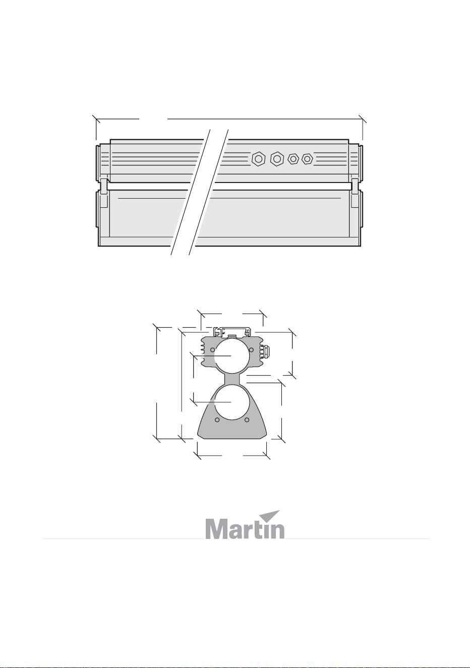
150
230
135
93
121
230
Height
incl.
mounting
bracket
242
1257
Dimensions
Measurements are in millimeters
©2007 Martin Professional A/S, Denmark. All rights reserved. No part of this manual may be
reproduced, in any form or by any means, without permission in writing from Martin Professional
A/S, Denmark. Information subject to change without notice. Martin Professional A/S and all
affiliated companies disclaim liability for any injury, damage, direct or indirect loss,
consequential or economic loss or any other loss occasioned by the use of, inability to use or
reliance on the information contained in this manual.
P/N 35000191, Rev. A
Safety information 3
Safety information
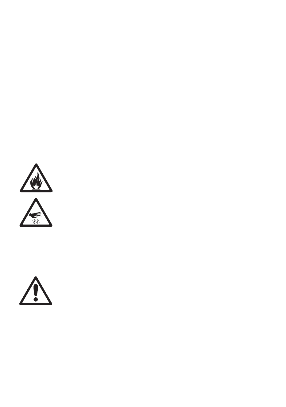
The following symbols are used to identify important safety information:
DANGER! This product is not for household use. It presents risks of
injury due to electric shock, fire, burns and falls if safety precautions
are not followed.
Read this manual before installing, powering, operating or servicing
the luminaire. Follow the safety precautions listed below, and observe
all warnings in this manual and on the luminaire. Use the luminaire
only as described in this manual and in accordance with local laws
and regulations. Refer any operation not described in this manual to a
qualified technician.
If you have any questions about how to operate this luminaire safely, contact
your Martin Architectural supplier or call the Martin 24-hour service hotline
on +45 70 200 201.
Protection from electric shock
• Do not use the luminaire if any cable, seal, cover, housing or other
component is cracked, deformed or damaged in any way.
• Isolate the luminaire from power and lock out power before removing or
installing a tube, fuses or any part
WARNING!
Read the safety precautions in this
section before installing, powering,
operating or servicing this product.
Danger! Safety
hazard. Risk of
personal injury or
death.
Danger! Hazardous
voltage. Contact
will cause electric
shock.
Danger! Fire
hazard.
Warning! Burn
hazard. Hot
surface. Do not
touch.
4 Cyclo IP65 Directional user manual
• Always ground (earth) the luminaire electrically.
• Use only a source of AC power that complies with local building and
electrical codes and has both overload and ground (earth) fault protection.
• Ensure that the AC power distribution system includes a means of
isolating all installed devices from power and locking out power during
service.
• Ensure that all components in the AC power distribution circuits (cables,
junction boxes, etc.) are protected from water and airborne particles to
IP67 or higher, are suitably dimensioned for the current and power
requirements of the devices installed, and are of suitable type for the
location (including water, pollution, temperature and UV resistance).
• Do not expose the luminaire to a high-pressure water jet.
• Do not immerse the luminaire in water or install it in a location where
flooding may occur.
• Refer all service not described in this manual to a Martin service
technician.
Protection from burns and fire
• Do not operate the luminaire if the ambient temperature (T
a
) exceeds 40°
C (104° F).
• Keep flammable materials well away from the luminaire.
• Allow the luminaire to cool for 15 minutes before servicing.
• Do not attempt to bypass thermostatic switches or fuses. Replace
defective fuses with ones of the specified type and rating only.
• Do not modify the luminaire. Install only genuine Martin parts and
approved fluorescent tubes of the type and wattage specified for the
armature.
• Provide a minimum clearance of 25 mm (1 inch) and unobstructed airflow
around the luminaire.
• Do not mask or modify light output with filters or other materials.
Protection from injury due to falls
• Block access below the work area and work from a stable platform
whenever installing, servicing or removing the luminaire.
• Ensure that all supporting structures, surfaces, fasteners and lifting
equipment can bear the weight of all the devices they are intended to
support plus an adequate safety margin, and that they conform to local
building and safety regulations.
• Use fasteners that have sufficient corrosion resistance, dimensions and
strength to mount the luminaire safely. Any nuts used must be self-
locking.
• Ensure that all components and installation fittings are securely fastened.

Contents
Safety information . . . . . . . . . . . . . . . . . . . . . . . . . . . . . . . . . . . . . 3
Product overview. . . . . . . . . . . . . . . . . . . . . . . . . . . . . . . . . . . . . . . 6
Introduction . . . . . . . . . . . . . . . . . . . . . . . . . . . . . . . . . . . . . . . . . . . . 7
Installation . . . . . . . . . . . . . . . . . . . . . . . . . . . . . . . . . . . . . . . . . . . . . 8
Included items . . . . . . . . . . . . . . . . . . . . . . . . . . . . . . . . . . . . . . . . . . . 8
Access to tube module . . . . . . . . . . . . . . . . . . . . . . . . . . . . . . . . . . . . 9
Access to connections compartment . . . . . . . . . . . . . . . . . . . . . . . . 10
Mounting . . . . . . . . . . . . . . . . . . . . . . . . . . . . . . . . . . . . . . . . . . . . . . 11
Orientation and adjustment . . . . . . . . . . . . . . . . . . . . . . . . . . . . . . . . 12
Cable entry . . . . . . . . . . . . . . . . . . . . . . . . . . . . . . . . . . . . . . . . . . . . 15
AC power . . . . . . . . . . . . . . . . . . . . . . . . . . . . . . . . . . . . . . . . . . . . . 18
Linking luminaires for DMX and synchronized operation . . . . . . . . . 21
Operation: general . . . . . . . . . . . . . . . . . . . . . . . . . . . . . . . . . . . . 27
Fluorescent tube lifetimes and performance . . . . . . . . . . . . . . . . . . . 27
Avoiding condensation and humidity. . . . . . . . . . . . . . . . . . . . . . . . . 27
Operation in extreme ambient temperatures. . . . . . . . . . . . . . . . . . . 28
Stand-alone operation. . . . . . . . . . . . . . . . . . . . . . . . . . . . . . . . . 29
Stand-alone operation settings . . . . . . . . . . . . . . . . . . . . . . . . . . . . . 30
Single stand-alone operation . . . . . . . . . . . . . . . . . . . . . . . . . . . . . . 31
Master/
client st
and-alone operation . . . . . . . . . . . . . . . . . . . . . . . . . 31
DMX-controlled operation. . . . . . . . . . . . . . . . . . . . . . . . . . . . . 35
DMX control functions . . . . . . . . . . . . . . . . . . . . . . . . . . . . . . . . . . . . 35
Service . . . . . . . . . . . . . . . . . . . . . . . . . . . . . . . . . . . . . . . . . . . . . . . . 36
Cleaning . . . . . . . . . . . . . . . . . . . . . . . . . . . . . . . . . . . . . . . . . . . . . . 36
Tube replacement . . . . . . . . . . . . . . . . . . . . . . . . . . . . . . . . . . . . . . . 36
Main fuse replacement . . . . . . . . . . . . . . . . . . . . . . . . . . . . . . . . . . . 39
Voltage setting . . . . . . . . . . . . . . . . . . . . . . . . . . . . . . . . . . . . . . . . . 40
Troubleshooting . . . . . . . . . . . . . . . . . . . . . . . . . . . . . . . . . . . . . . . 41
DMX protocols. . . . . . . . . . . . . . . . . . . . . . . . . . . . . . . . . . . . . . . . 42
Cyclo IP65 Directional specifications . . . . . . . . . . . . . . . . . 43
6 Cyclo IP65 Directional user manual
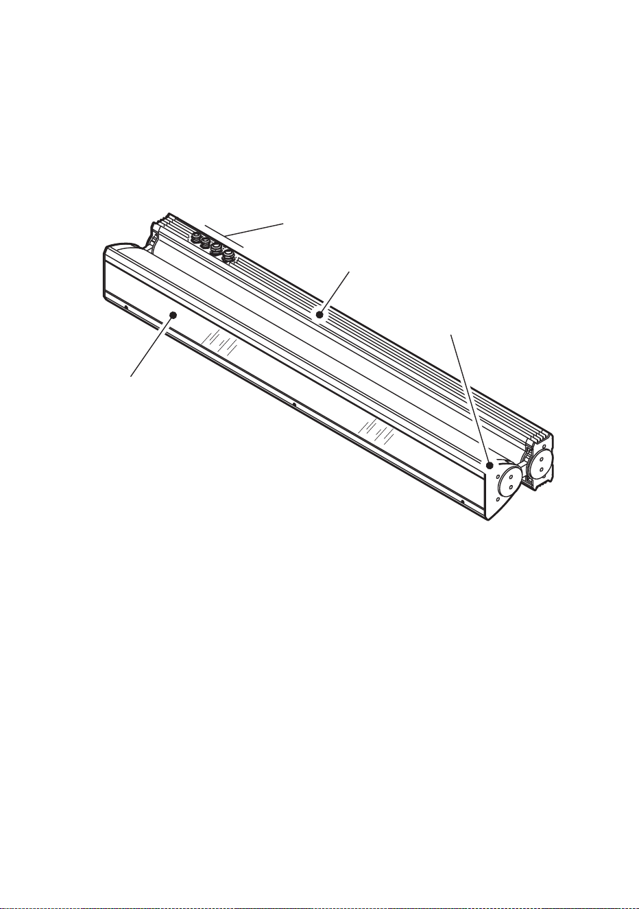
A
B
D
C
Product overview
A – Tube module
B – Base module
C – Front cover
D – Metal cable glands (if used)

Introduction 7
Introduction
Thank you for selecting a luminaire from the Martin Architectural
®
Cyclo
IP65 Directional series. Cyclo IP65 Directional luminaires are fluorescent
tube-based dynamic color-changing luminaires designed for illumination of
walls and surfaces. Dimmable 54 watt T5 fluorescent tubes combine high
efficiency, bright color and long lamp life. Luminaires are designed for
surface mounting, and adjustable arms allow tilting through a wide range of
angles.
Cyclo IP65 Directional luminaires offer independent 0-100% control of tube
intensity using a standard DMX controller. They can also be programmed to
run stand-alone light shows alone or in synchronized groups.
Two models are available. The 03 has red, green and blue tubes, allowing
RGB additive color mixing. The 04 has red, green and blue tubes plus a cool
daylight white tube, allowing RGBW color mixing. The color temperature of
the white tube’s output can be controlled using the colored tubes.
Luminaires are dustproof and protected from water projections and low-
pressure water jets to IP65. A self-purging humidity valve eliminates
condensation. Luminaires can start and operate with tubes dimmed to 1%
light output in ambient temperatures as low as -20° C (-4° F).
Versions are available to suit the following voltage ranges:
• 120 V models accept 100-130 V nominal AC power at 50/60 Hz.
• 230 V models accept 200-240 V nominal AC power at 50/60 Hz.
Martin Architectural can offer expert assistance with planning an installation,
if desired.
Installation, on-site service and maintenance can be provided worldwide by
the Martin
®
Global Service organization and its authorized agents.
Choosing a Martin service contract gives owners access to Martin’s
expertise and product knowledge in a partnership that will ensure the
highest level of performance throughout the product’s lifetime.
The most recent version of this user manual is available from the Support
area of http://www.martin-architectural.com

8 Cyclo IP65 Directional user manual
Installation
DANGER! Read “Safety information” on page 3 before attempting to
install this product.
The safety and suitability of lifting equipment, installation location,
anchoring method, mounting hardware and electrical circuits are the
responsibility of the installer. All local safety regulations and legal
requirements must be observed when installing and connecting the
Cyclo IP65 Directional. Installation must be carried out by qualified
professionals only.
This section describes how to install the luminaire, including how to connect
it to power and control data cables, and how to set it up for DMX control or
stand-alone operation.
We recommend that you read the Installation section of this manual and
familiarize yourself with the procedures involved before starting to install
luminaires. If you are not familiar with DMX, pay particular attention to the
section on setting DMX addresses.
Included items
Cyclo IP65 Directional luminaires are supplied with the following items:
• Osram T5 fluorescent tubes (installed)
• Surface-mounting bracket.
• Two TET 5-7 Thorsman rubber membrane cable glands (installed) for
data cable entry: cable diameter 5-7 mm (0.20-0.28 in.)
• Two TET 10-14 Thorsman rubber membrane cable glands (installed) for
power cable entry: cable diameter 10-14 mm (0.40-0.55 in.)
• Two M25 metal blanking plugs (installed) for unused power cable entry
holes.
• Two M16 metal blanking plugs (installed) for unused data cable entry
holes.
• Two M25 metal IP68 cable glands (supplied loose) for AC power cable
entry: cable diameter 7 - 15 mm (0.28 - 0.6 in.).
• Two M16 metal IP68 cable glands (supplied loose) for data cable entry:
cable diameter 5 - 12 mm (0.2 - 0.45 in.).
Installation 9
Access to tube module
Various operations described in this manual require access to the inside of
the module that contains the tubes. To access the inside of the tube module:
1. Isolate the luminaire from power and ensure that power cannot be
reconnected.
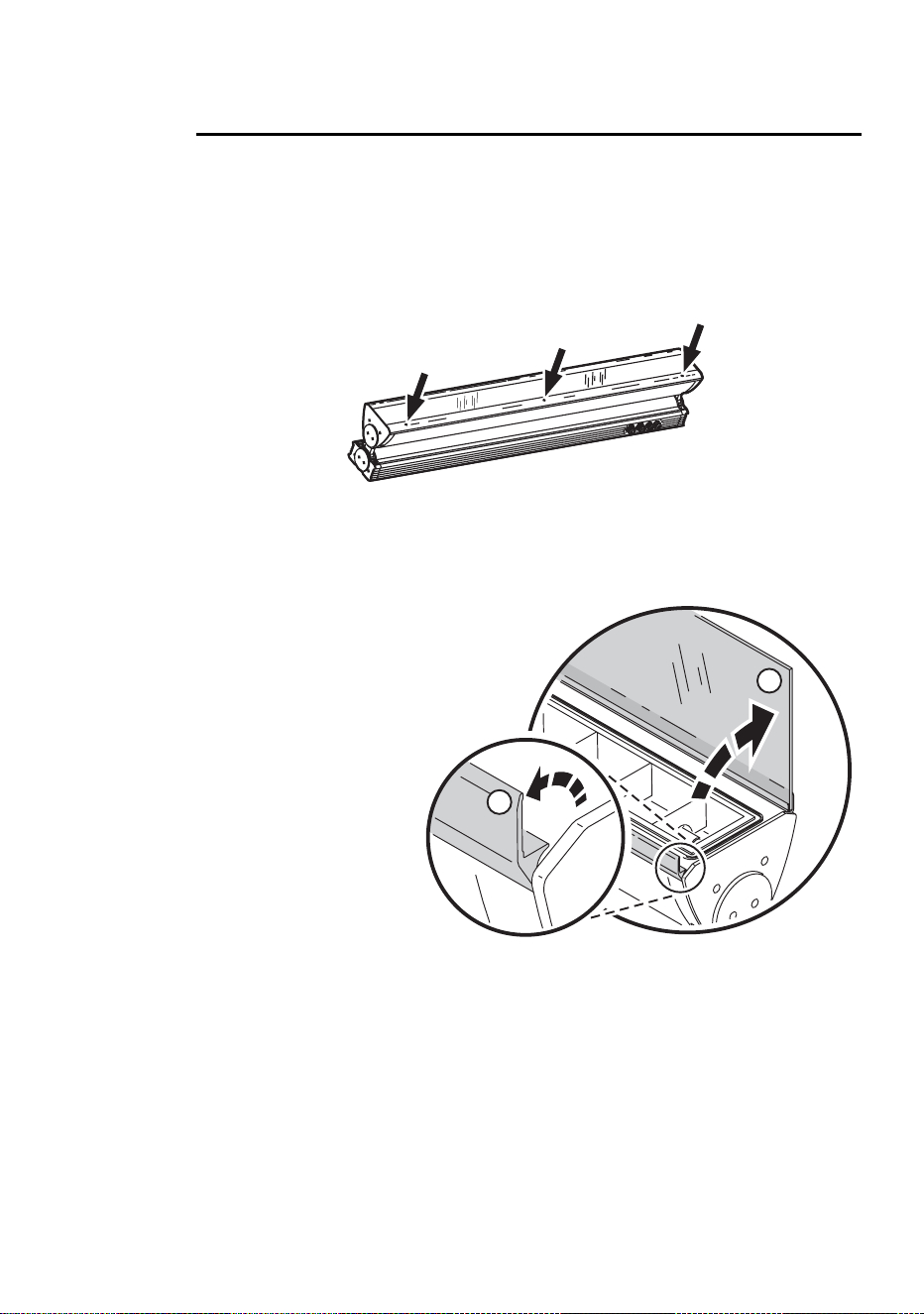
2. See Figure 1. Loosen the three front cover release screws in the hinged
front cover release flap until they turn freely.
3. See Figure 2. Lift
the release flap (A)
and then lift the
hinged front cover
(B). If you need to
lever the release
flap up, use a
plastic or wooden
object, as a metal
object may
damage the glass.
Avoid damaging
seals while you are
working.
4. To close the front
cover, first close
the cover (B), then
close the release
flap (A) so that it clips down over the cover. The seals on the inside faces
of covers must be in perfect condition to maintain their waterproof
qualities. Avoid damaging them. Any seal that is not in perfect condition
must be replaced by a Martin service agent.
.
Figure 1: Front cover release screws
A
B
Figure 2: Opening the front cover
10 Cyclo IP65 Directional user manual
Access to connections compartment
Various operations described in the is manual require access to the
connections compartment in the base module. To access the connections
compartment:
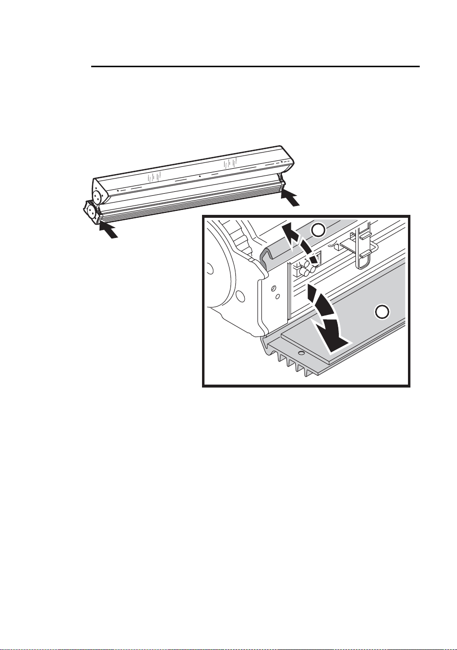
1. See Figure 3. Remove the two screws from the ends of the connections
compartment cover.
2. Open the hinged release flap (A) and then open the hinged cover (B).
Avoid damaging the seal on the inside of the cover.
3. To close the connections compartment, first close the hinged cover (B),
then close the release flap (A) so that it clips down over the cover. The
seals on the inside faces of covers must be in perfect condition to
maintain their waterproof qualities. Avoid damaging them. Any seal that
is not in perfect condition must be replaced by a Martin service agent.
4. Tighten the two screws at either end of the cover before applying power.
A
B
Figure 3: Opening the connections compartment cover
Installation 11
Mounting
DANGER! It is the installer’s responsibility to ensure that the
installation is safe and that all local safety regulations and legal
requirements are observed when mounting the Cyclo IP65 Directional.
The Cyclo IP65 Directional can be surface-mounted on a floor, wall or
ceiling. To surface-mount the Cyclo IP65 Directional:
1. Ensure that the mounting surface is flat and can support the weight of all
the devices to be installed on it. Allow 25 mm (1 inch) of free space
around each luminaire.
2. Using the mounting bracket as a guide, mark up and drill holes in the
mounting surface to take mounting fasteners.
3. Fasten the mounting bracket to the surface with at least two fasteners
that have sufficient corrosion resistance and strength to mount the
luminaire safely. Choice of mounting hardware will depend on the
installation, but use high-quality corrosion-resistant fasteners with
recommended minimum properties grade A4-70 (ISO 3506), or grade 8.8
(ISO 898-1). Any nuts used must be self-locking.
4. Check that the bracket is not distorted and is securely attached to the
mounting surface.
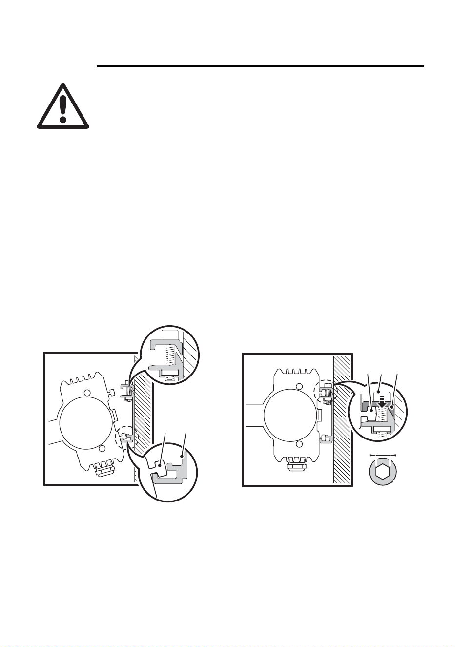
5. See Figure 4. To install the luminaire on the mounting bracket, hook the
raised T-section (A) on the lower side of the luminaire base into the
channel (B) on the mounting bracket, then swing the luminaire up so that
1
A B
5mm
2
C E D
Figure 4: Installing on the mounting bracket
12 Cyclo IP65 Directional user manual
the T-section (C) on the upper side of the base passes behind the
retaining rail (D).
6. Tighten the retaining screws (E) so that the retaining rail (D) grips the T-
section (C) tightly. Check that the luminaire is held securely.
Orientation and adjustment
Important! The Cyclo IP65 Directional support arms must both
be fixed at the same angle. Do not twist the luminaire in the
support arms, or you may deform the product and make it
impossible to obtain a waterproof seal.
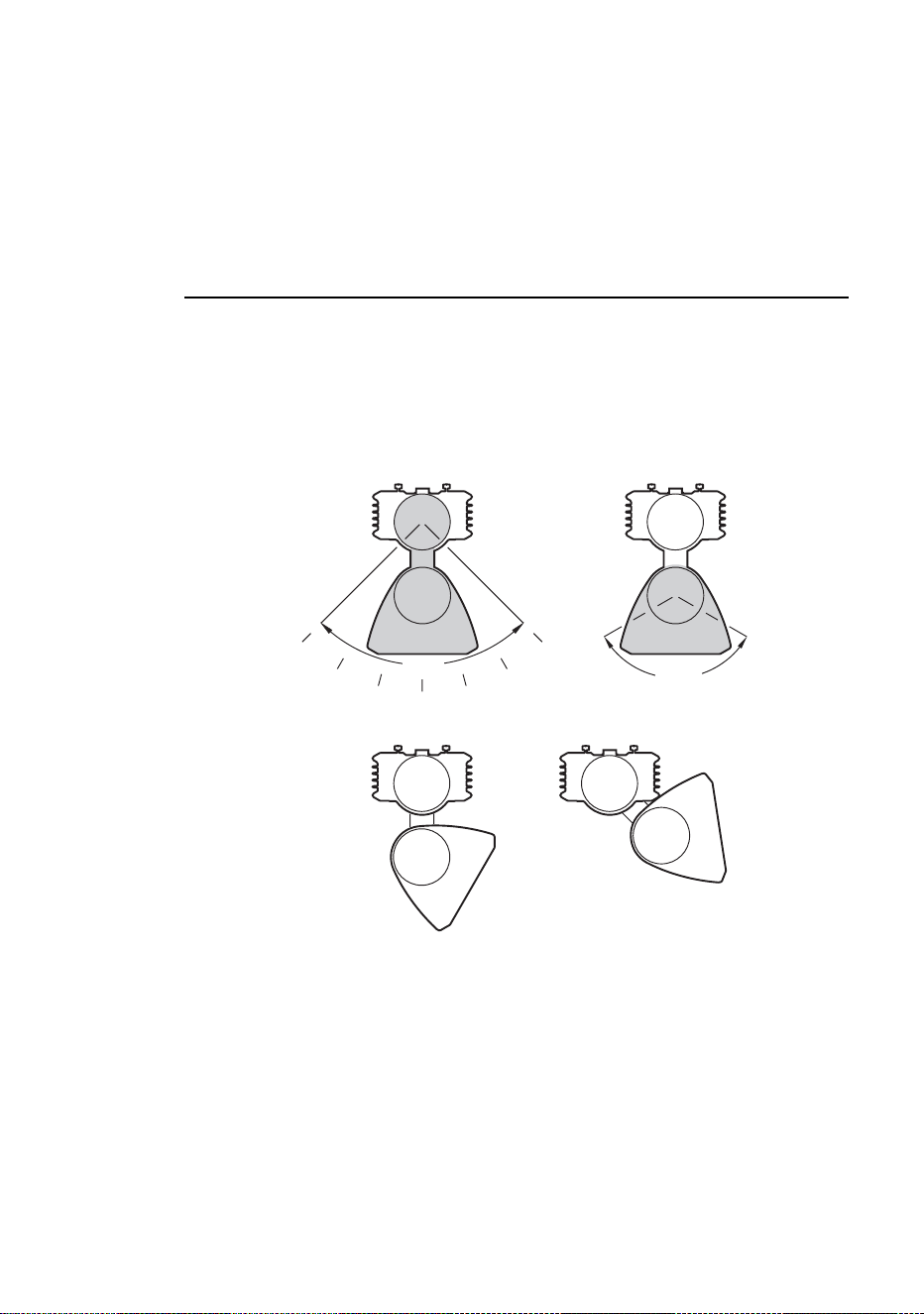
The Cyclo IP65 Directional can be installed in any orientation.
See Figure 5. The angle of the support arms can be adjusted in the base
module, and the tube module can be rotated in the support arms, allowing a
wide range of tilt angles.
90°
0°
15°
30°
45°
15°
30°
45°
120°
0°
60°
= 60°
= 60°
60°
45°
= 105°
= 105°
Figure 5: Tilt angle adjustment
Installation 13
Adjusting the support arm angle
To adjust the angle of the support arms in the base module:
1. Ensure that the luminaire is securely mounted and isolated from power.
2. Open the connections compartment as described in “Access to
connections compartment” on page 10.
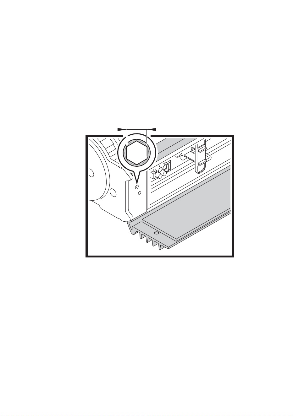
3. See Figure 6. Support the weight of the tube module. Loosen the arm
adjustment screws at both ends of the base module with a long Allen key,
tilt the arms to the desired angle and retighten slowly, rocking the tube
module up and down slightly while you tighten so that the adjustment
screws engage correctly in the cutouts in the arm.
4. Reinstall the connections compartment cover as described in “Access to
connections compartment” on page 10.
3mm
Figure 6: Arm-to-base adjustment screws
14 Cyclo IP65 Directional user manual
Adjusting the tube module tilt angle
To rotate the tube module in the support arms:
1. Ensure that the luminaire is securely mounted and isolated from power.
1. Open the front cover as described in “Access to tube module” on page 9.
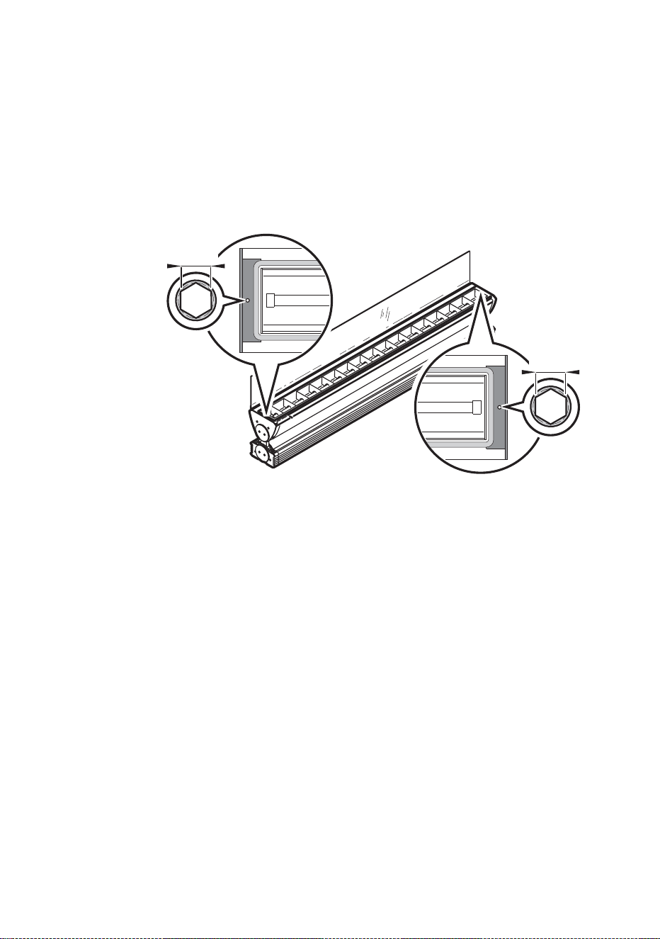
2. See Figure 7. Loosen both the tilt adjustment screws with a long Allen
key, rotate the tube module to the desired angle, and retighten.
3. Reinstall the front cover as described in “Access to tube module” on page
9.
3mm
3mm
Figure 7: Tube module tilt adjustment screws
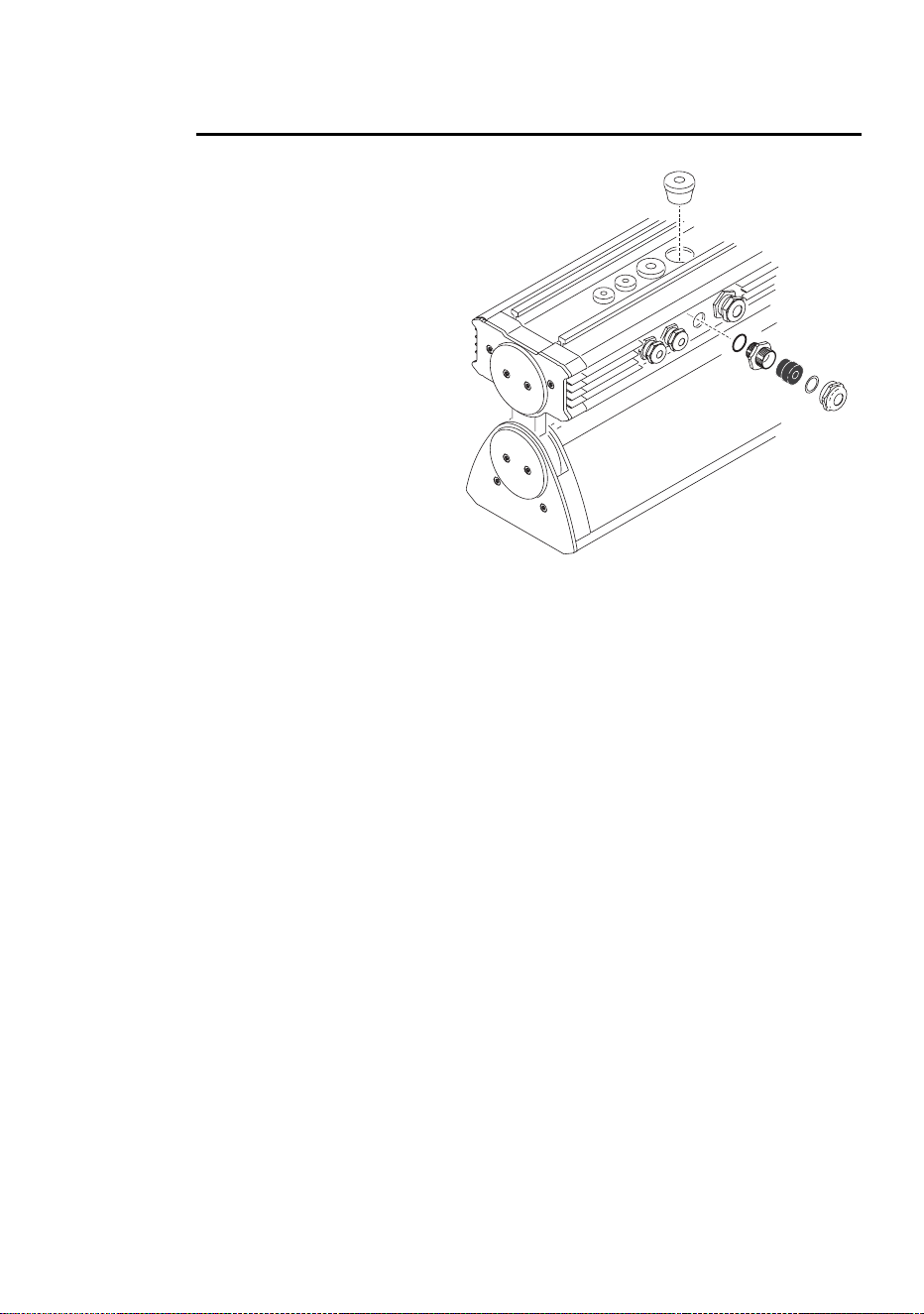
Installation 15
Cable entry
Two types of seal can be
used for cable entry:
Thorsman rubber
membrane cable glands
(see Figure 9) installed in
the base module and
metal cable glands (see
Figure 10) packed loose
with the product. If the
metal glands are used,
blanking plugs must be
removed and replaced
with metal glands.
Use the larger glands for
power cable entry and the
smaller glands for DMX
data cable entry.
Cable glands may need to
be replaced in the
following situations:
• If power or data cable is
used that is not within the diameters specified under “Included items” on
page 8, new cable glands that match cable diameter must be obtained
from Martin or an electrical supplier.
• Rubber and metal glands must be replaced with new items if cable in an
existing installation is replaced with cable of a different diameter.
• Used rubber membrane glands must be replaced with new unpierced
items or replaced with blanking plugs if they are no longer used for cable
entry.
• If metal cable glands are installed, they must be replaced with blanking
plugs if no longer used for cable entry.
Replacement rubber membrane glands must have the following
characteristics:
Temperature range . . . . . . . . . . . . . . . . . . . . -20° to +70°C or better
Ingress protection rating . . . . . . . . . . . . . . . . . . . . . . . . IP67 or IP68
Installation plate thickness . . . . . . . . . . . . 0.5-4.0 mm (0.02-0.17 in.)
Power cable gland installation hole diameter . . . . . .23 mm (0.91 in.)
Data cable gland installation hole diameter . . . . . . . 16 mm (0.63 in.)
Figure 8: Cable gland options
16 Cyclo IP65 Directional user manual
Replacement metal glands must have the following characteristics:
Temperature range: . . . . . . . . . . . . . . . . . . . -20° to +70°C or better
Ingress protection rating: . . . . . . . . . . . . . . . . . . . . . . . IP67 or IP68
Power cable gland thread size: . . . . . . . . . . . . . . . . . . . . . . . . . M25
Data cable gland thread size: . . . . . . . . . . . . . . . . . . . . . . . . . . M16
Minimum entry thread length: . . . . . . . . . . . . . . . . . 10 mm (0.4 in.)
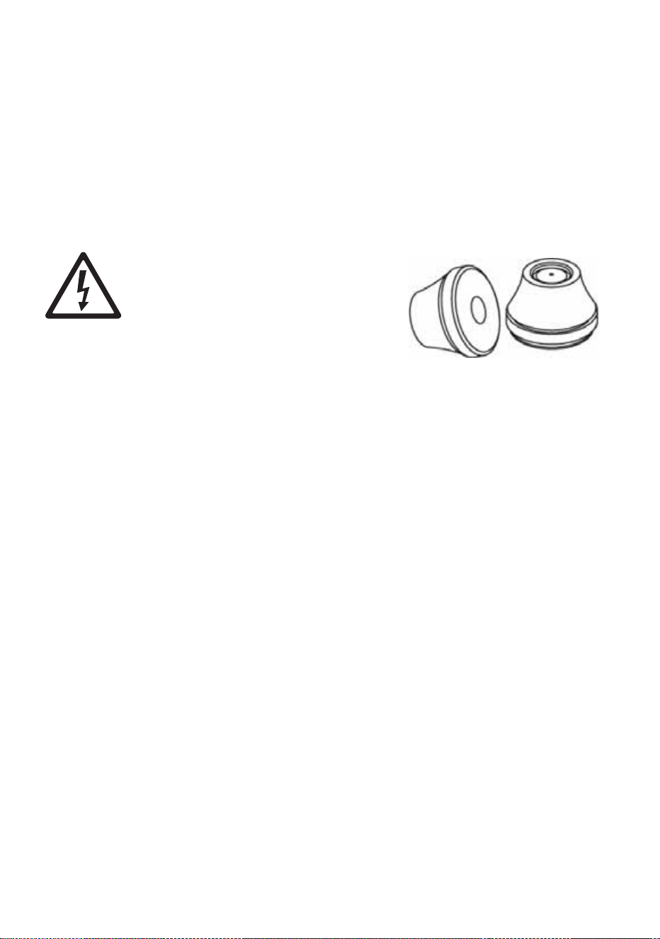
Installing cable using rubber membrane glands
DANGER! Using a rubber membrane
gland involves making a hole in the
membrane. A used gland is therefore
only waterproof with cable installed. If
the cable is removed, the hole in the
housing must be sealed with a
blanking plug or new gland.
To install cable using a rubber gland:
1. Push a round spiked object through
the center of the membrane from the
outside of the housing just enough to pierce it. Do not enlarge the hole or
remove rubber from the membrane.
2. Push cable through the gland from the outside of the housing.
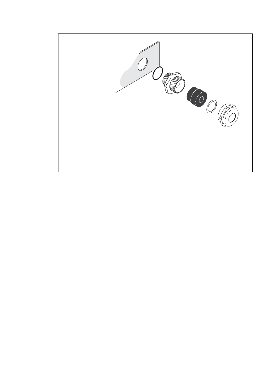
Installing cable using metal cable glands
Two sizes of metal cable gland are supplied loose with the product. Use the
larger glands for power cable entry and the smaller glands for DMX data
cable entry.
To install cable using a metal cable gland:
1. Remove a blanking plug that matches the cable gland size from the base
module housing.
Figure 9: Thorsman rubber
membrane cable glands
Installation 17
2. See Figure 10. Dismantle the cable gland.
3. Ensure that there is a rubber O-ring A on the housing end of the cable
entry B, and screw this end into the threaded hole in the housing. Tighten
until the O-ring A makes a water-resistant seal against the outer surface
of the housing. Do not over-tighten, as this may damage the seal or
housing.
4. Thread the cable through the compression nut E, washer D, gland C, and
cable entry B into the housing.
5. Allow approx. 20 cm (8 in.) of cable slack inside the housing. Prevent the
cable entry from turning and tighten the compression nut sufficiently to
make a water-resistant seal. Do not over-tighten, as this may damage the
gland. Check that the cable is firmly gripped in the rubber gland.
Figure 10: Metal cable gland
A
B
C
D
E
A – O-ring seal
B – Cable entry
C – Gland
D – Washer
E – Compression nut
18 Cyclo IP65 Directional user manual
AC power
DANGER! It is the installer’s responsibility to ensure that all power
cable and equipment is adequately dimensioned and of appropriate
type for the installation, and that all local safety regulations and legal
requirements are observed when installing and connecting the Cyclo
IP65 Directional.
Current and power data are given in the Specifications section on page 43.
Inrush currents and electronic circuit-breakers
When fluorescent tubes with ECG (electronic control gear) systems are
switched on at the AC wave peak, a larger current surge occurs than with
conventional ballasts. If a large number of luminaires are switched on
simultaneously, this inrush current can trip electronic circuit breakers. To
avoid this in large installations, either switch on luminaires at intervals or
limit the number of luminaires per 16 A electronic circuit breaker to
approximately ten luminaires.
RCDs and common neutral conductors
Many fixed installations use common neutral conductors in branch circuit
distribution boxes. To avoid unintentional tripping of the RCD (residual
current device, or ground fault/earth leakage circuit breaker), ensure that
each luminaire’s neutral conductor is connected to AC power via the same
RCD as the live conductor.
Leakage to ground and RCDs
Each ECG “leaks” a total current of maximum 0.5 mA to ground (earth).
Luminaires must be correctly connected to ground so that this “leakage”
current can be absorbed.
Allow for the “leakage” current from ECGs when connecting luminaires to a
circuit that has an RCD for ground fault protection, otherwise the RCD may
trip unintentionally. Bear in mind that RCDs are rated at their maximum trip
current, and that some RCDs rated 30 mA may trip when leakage to ground
is as low as 20 mA.
RCDs can also be tripped by the inrush current when tubes are switched on.
To avoid unintentional tripping of RCDs:
1. Distribute power using 3 phases and install 3-phase RCDs.
2. If it is both safe and legal, use RCDs with a trip current rating higher than
30 mA. When considering this option, the installer must ensure that all
local building and electrical regulations are respected. Maximum legally
Installation 19
permitted RCD trip current ratings are normally stated in national
electrical and building codes.
3. Install surge current-resistant RCDs.
Connecting to power
A screw clamp is provided for connecting the luminaire to the power cable’s
earth conductor, and a block of spring-loaded clamp terminals are provided
for connecting the luminaire to the power cable’s live and neutral power
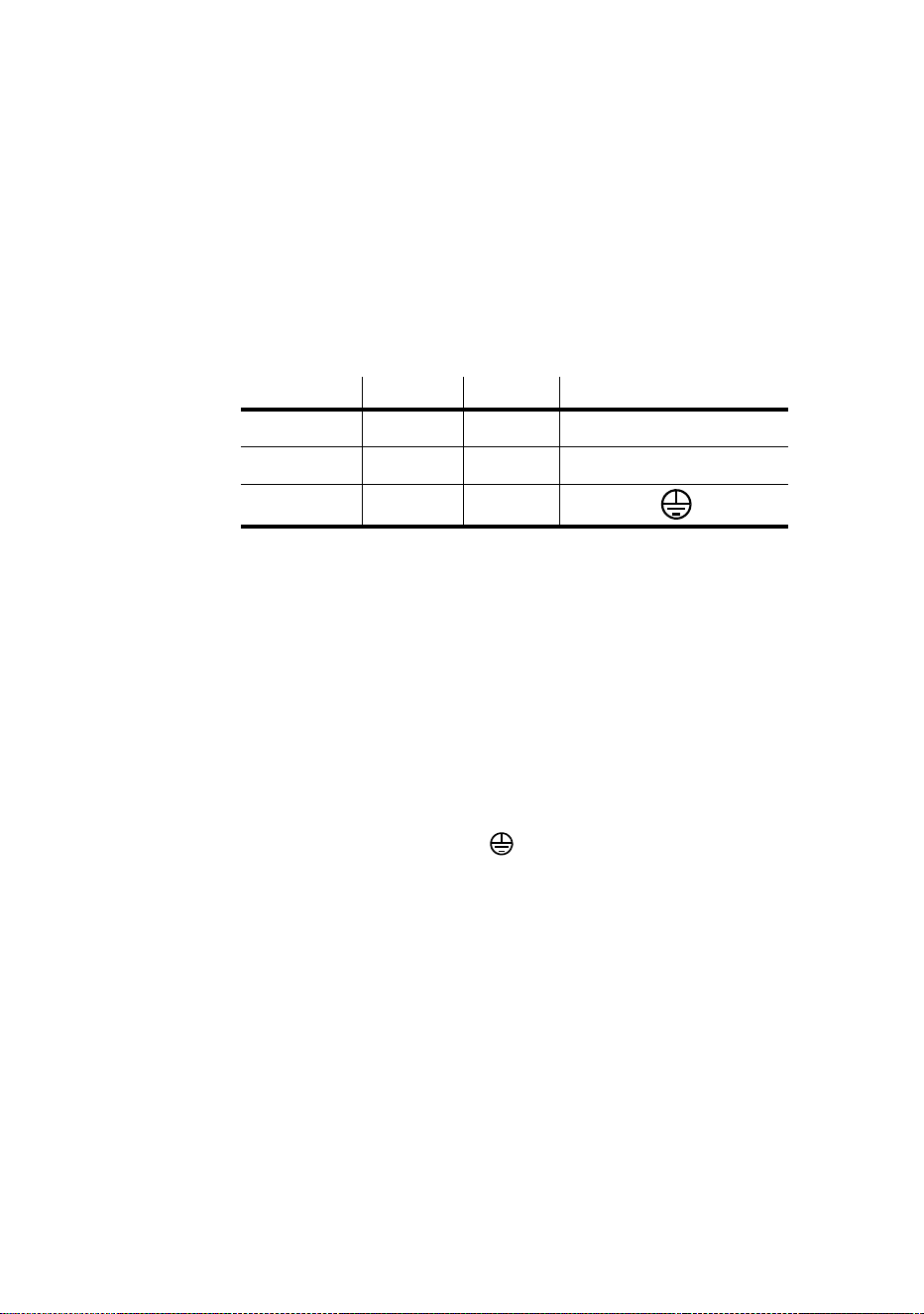
conductors.Some common color-coding systems for power wiring are given
below:
To connect to AC power:
1. Ensure that power cannot be applied to the cable during installation.
2. Open the connections compartment as described in “Access to
connections compartment” on page 10.
3. Pass the power input cable through a cable gland as described in “Cable
entry” on page 15 so that approximately 20 cm (8 in.) of cable is free
inside the luminaire, and prepare the end of the cable for connection.
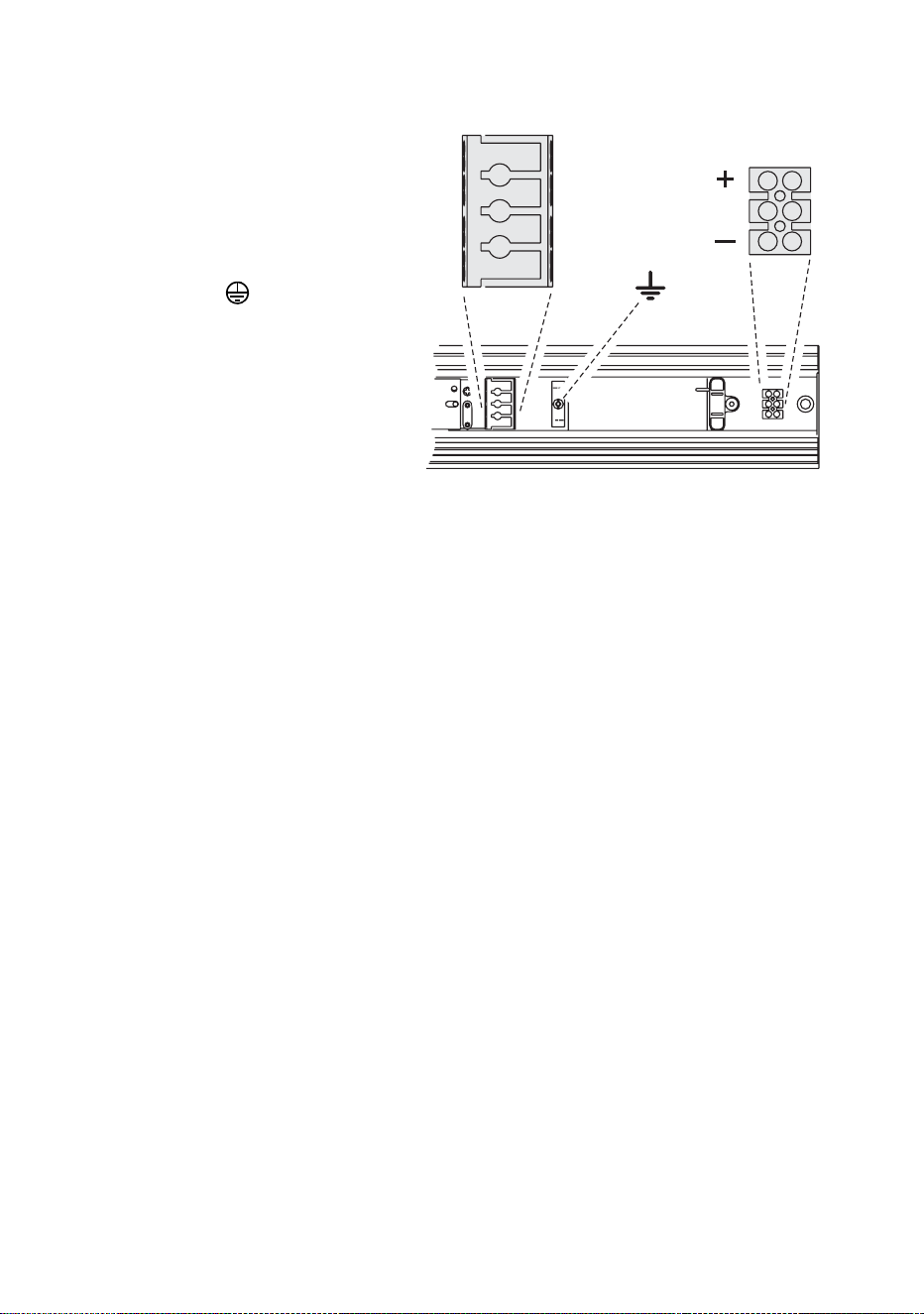
4. See Figure 11. Four spring-loaded terminals marked L1, L2, L3 and N
and one screw clamp marked are provided for power cable
connection. The terminals marked L2 and L3 are not used to supply
power to the luminaire and are provided only to allow phase conductors
to be connected if power is supplied from a 3-phase system (see
“Connecting to a 3-phase system” on page 20).
Wire (EU) Wire (US) Pin Marking on luminaire
brown black live L1
blue white neutral N
yellow/green green ground
Table 1: Power cable color-coding systems
20 Cyclo IP65 Directional user manual
5. Connect the
conductors in the
power input cable as
follows:
• Connect the
ground (earth) wire
to the screw
terminal marked
close to the
power terminals.
• Connect the
neutral wire to the
spring-loaded
power terminal
marked N
• Connect the live
wire to the spring-
loaded power
terminal marked
L1.
6. If power is to continue to another luminaire, pass power output cable
through a cable gland as described in “Cable entry” on page 15 and
prepare the end of the cable for connection. Each spring-loaded terminal
has two holes. One hole now contains a conductor from the input cable
and one is available for a conductor from the output cable. Using the
spare holes, connect the conductors in the power output cable as
described under point 5. above.
Connecting to a 3-phase system
If you are supplying luminaires with power from a 3-phase system, the live
conductor in the power input cable that you connect to terminal L1 will be
one of the phases. Connect one of the remaining phases to terminal L2 and
the last remaining phase to terminal L3.
To distribute the load evenly over the 3 phases, connect phase 1 to terminal
L1 on one-third of the luminaires in the installation, phase 2 to terminal L1
on one-third of the luminaires, and phase 3 to terminal L1 on the remaining
one-third of the luminaires. Terminals L2 and L3 do not supply power to the
luminaire and are provided simply to allow phase conductors in separate
lengths of power cable to be joined.
To avoid confusion, each time you install a power output cable to take power
to the next luminaire, connect each phase conductor in the power output
cable to the terminal used for that phase conductor in the power input cable.
N
N
L1
L1
L2
L2
L3
L3
Shield
Shield
Figure 11: Power and DMX connections
DMX terminalsPower terminals

Installation 21
After making power connections
If you are installing DMX data cables, continue to the next section.
Otherwise, close the connections compartment as described in “Access to
connections compartment” on page 10.
Linking luminaires for DMX and
synchronized operation
You need to create a data link to:
• Control luminaires with a DMX control device.
• Operate two or more Cyclo IP65 Directionals in master/client stand-alone
mode, where all luminaires run a synchronized light show without a
separate DMX control device.
A reliable data connection requires suitable cable. CAT 5 (category 5) UTP
(unshielded twisted pair) network cable is suitable for this purpose. The
minimum recommended wire size is 0.2 mm
2
(24 AWG) for runs up to 300
meters (1000 ft.) and 0.322 mm
2
(22 AWG) for runs up 500 meters (1640 ft).
Your Martin Architectural supplier can advise and supply suitable cable.
Luminaires on a serial data link must be daisy-chained in one single line,
maximum 500 meters (1640 ft.) long, with maximum 32 luminaires. To
exceed 32 luminaires or 500 meters, or to add branches, an optically
isolated amplifier-splitter such as the Martin RS-485 Opto-Splitter (P/N
90758060) must be used.
A male 3-pin XLR connector can be fitted at the controller end of the data
link to allow a standard connection to Martin DMX controller. The XLR
connector should be wired as follows:
• Pin 1: shield
• Pin 2: DMX - (cold)
• Pin 3: DMX + (hot)
To avoid ground (earth) loop interference, make sure that the DMX cable
shield does not come into contact with the shell or body of the XLR
connector.
A screw-type terminal block is provided in the connections compartment for
connecting the data link. The data input and data output cables must both
be connected to this terminal block. The data output may only be used to
relay data to one luminaire.
22 Cyclo IP65 Directional user manual
Connecting to control data
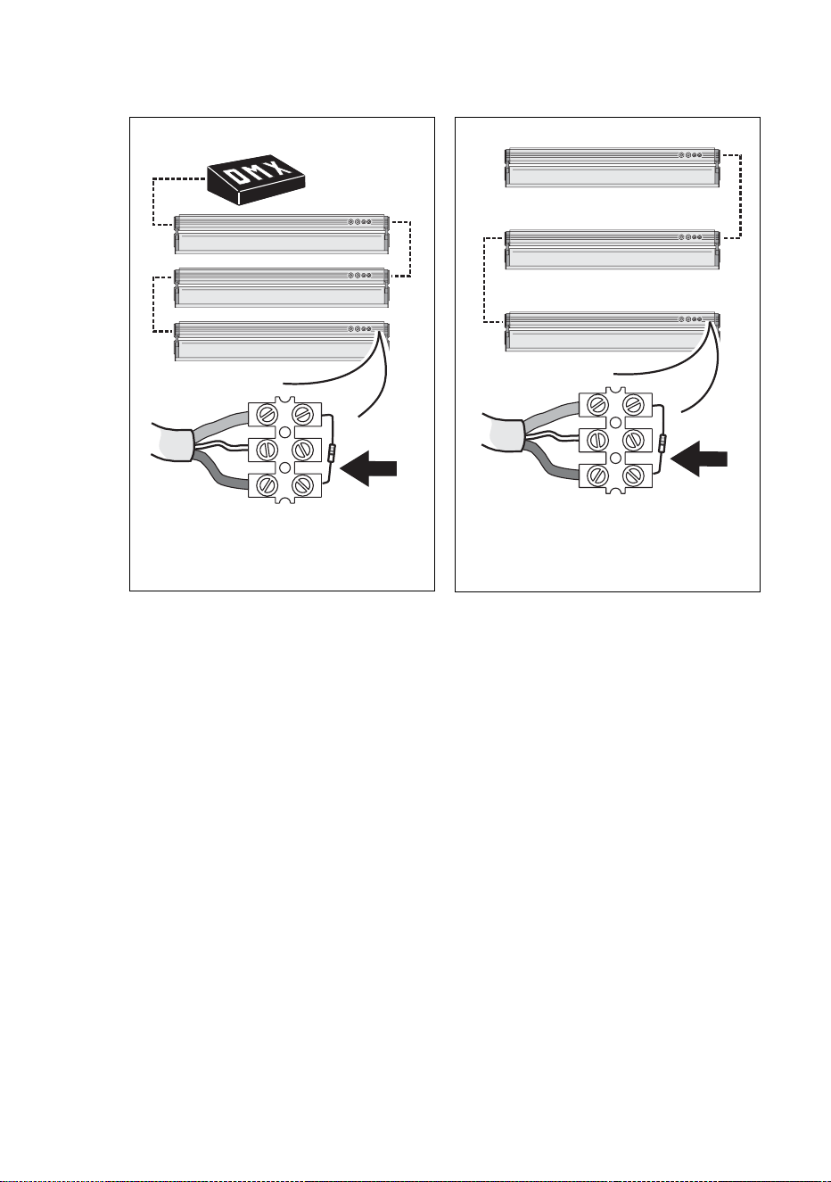
To create the data link:
1. If using a DMX control device, run suitable cable from the controller’s
DMX output to the first luminaire on the link.
2. Use an M16 cable gland to run the data cable through the housing (see
“Cable entry” on page 15).
3. Connect the data cable wires to the data terminal block (see“DMX
terminals” in Figure 11). Wiring polarity is labelled on the luminaire.
4. Continue connecting up to 32 luminaires using the above procedure.
5. Terminate the data link by connecting a 120 Ohm, 0.25 W resistor across
the + (hot) and - (cold) terminals of the last luminaire’s terminal block.
TIp! Random “flicker” and other unexplained control problems
during stand-alone master/FOLHQW operation can often be cured
by also connecting a 120 Ohm resistor across the + (hot) and -
(cold) terminals of the first luminaire’s data connection terminal
block.
Master
&OLHQW
&OLHQW
DMX controller
Master/FOLHQW linkDMX control link
120 Ohm resistor
120 Ohm resistor
Installation 23
Configuring luminaires for DMX or stand-alone
operation
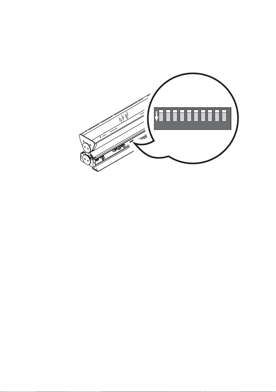
Each DMX model Cyclo IP65 Directional luminaire needs to be set up for
DMX or stand-alone operation using the DIP switch located on the circuit
board in the base module.
Configuring for DMX operation
DMX operation is enabled by setting pin 10 on the DIP switch to OFF. Pins
1 - 9 are then used to set the luminaire’s control address.
The Cyclo IP65 Directional uses one DMX channel to control each tube.
The DMX address, also known as the start channel, is the first of these
channels. It must be set on the luminaire (and selected on the DMX
controller) before the controller can send commands to the luminaire via a
data link. For example, a Cyclo 04 IP65 Directional with its DMX address set
to 101 uses channels 101, 102, 103 and 104 to control its four tubes.
Allow enough channels when setting the DMX address. If control channels
for two luminaires overlap, one of the luminaires will receive the wrong
commands.
If two or more Cyclo IP65 Directional luminaires share the same DMX
address, they will receive the same commands and respond identically.
Individual control will be impossible.
The default factory-set control address is ‘1’.
To set the Cyclo IP65 Directional’s DMX address:
1. Set DIP switch pin 10 to OFF.
1 2 3 4 5 6 7 8 910
ON
Figure 12: DIP switch
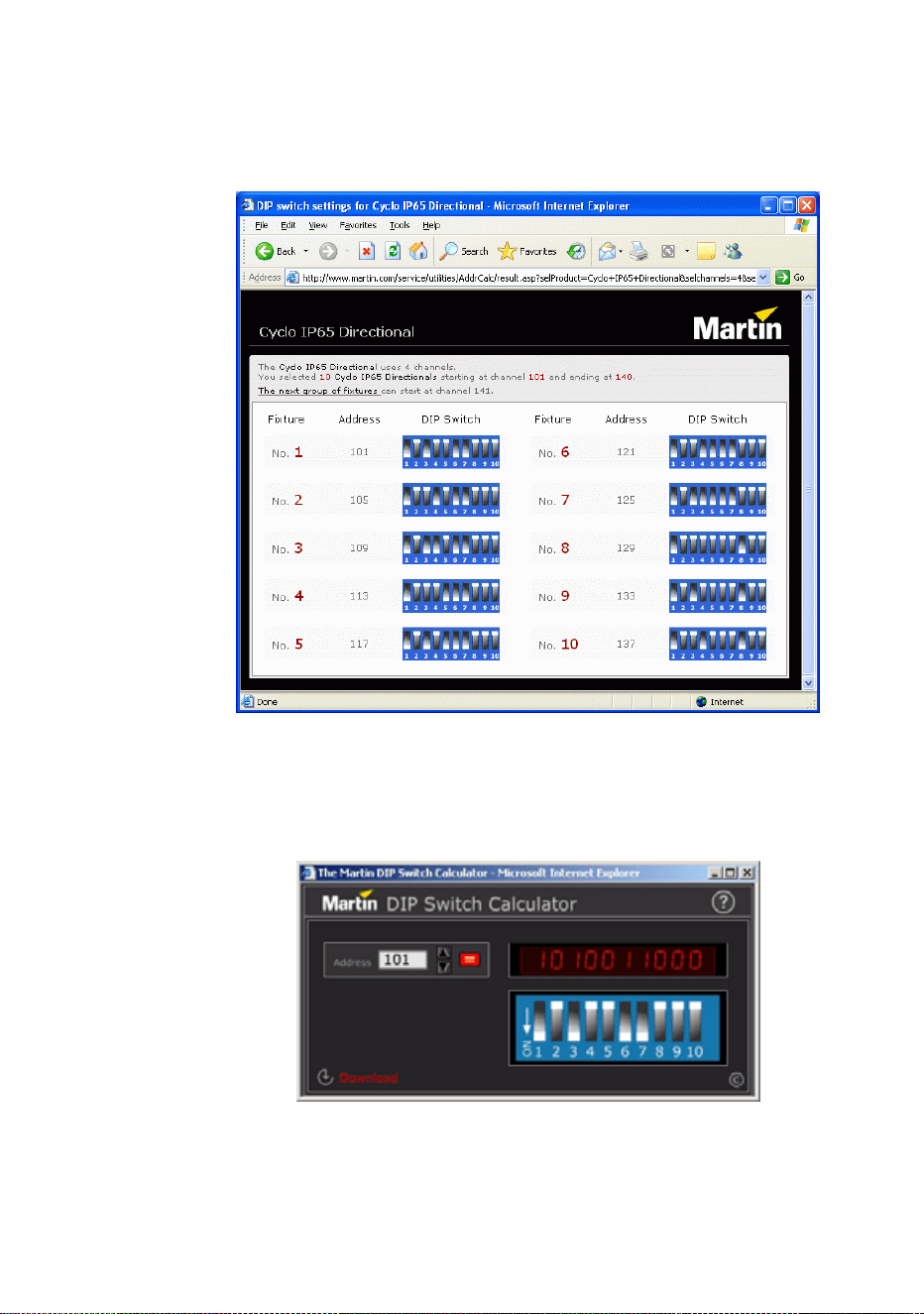
2. Decide on a DMX address for the luminaire. If you are calculating the
DMX addresses for multiple luminaires, save time by using the
online Martin Address Calculator at
http://www.martin.dk/service/utilities/AddrCalc/index.asp (see
illustration below).
3. You can also look up DIP switch settings using the Martin DIP
Switch Calculator, available for use and downloadable at
http://www.martin.dk/service/dipswitchpopup.htm
If you do not have Internet access, refer to "Table 2: DMX address
DIP switch settings" on page 25.
4. Set DIP switch pins 1 through 9 to ON (1) or OFF (0) with reference
to the table.
Installation 25
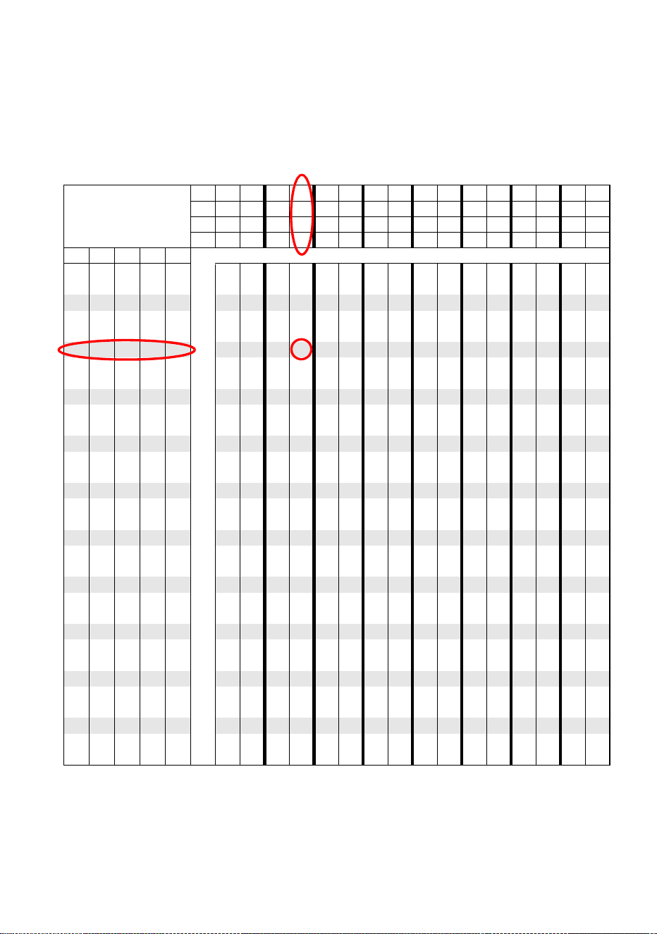
To use this table, first find the DMX address in the main block in the table.
Then read the settings for pins 1 - 5 to the left and read the settings for pins
6 - 9 above the address. “0” means OFF and “1” means ON.
For example, to set the DMX address to 101, you need to set DIP switch
pins 1, 3, 6 and 7 to ON, as highlighted in the table.
DIP switch pins setting
0 = OFF
1 = ON
#9 0 0 0 0 000011111111
#8 0 0 0 0 111100001111
#7 0 0 1 1 001100110011
#6 0 1 0 1 010101010101
#1 #2 #3 #4 #5
0 0 0 0 0 32 64 96 128 160 192 224 256 288 320 352 384 416 448 480
1 0 0 0 0 1 33 65 97 129 161 193 225 257 289 321 353 385 417 449 481
0 1 0 0 0 2 34 66 98 130 162 194 226 258 290 322 354 386 418 450 482
1 1 0 0 0 3 35 67 99 131 163 195 227 259 291 323 355 387 419 451 483
0 0 1 0 0 4 36 68 100 132 164 196 228 260 292 324 356 388 420 452 484
1 0 1 0 0 5 37 69 101 133 165 197 229 261 293 325 357 389 421 453 485
0 1 1 0 0 6 38 70 102 134 166 198 230 262 294 326 358 390 422 454 486
1 1 1 0 0 7 39 71 103 135 167 199 231 263 295 327 359 391 423 455 487
0 0 0 1 0 8 40 72 104 136 168 200 232 264 296 328 360 392 424 456 488
1 0 0 1 0 9 41 73 105 137 169 201 233 265 297 329 361 393 425 457 489
0 1 0 1 0 10 42 74 106 138 170 202 234 266 298 330 362 394 426 458 490
1 1 0 1 0 11 43 75 107 139 171 203 235 267 299 331 363 395 427 459 491
0 0 1 1 0 12 44 76 108 140 172 204 236 268 300 332 364 396 428 460 492
1 0 1 1 0 13 45 77 109 141 173 205 237 269 301 333 365 397 429 461 493
0 1 1 1 0 14 46 78 110 142 174 206 238 270 302 334 366 398 430 462 494
1 1 1 1 0 15 47 79 111 143 175 207 239 271 303 335 367 399 431 463 495
0 0 0 0 1 16 48 80 112 144 176 208 240 272 304 336 368 400 432 464 496
1 0 0 0 1 17 49 81 113 145 177 209 241 273 305 337 369 401 433 465 497
0 1 0 0 1 18 50 82 114 146 178 210 242 274 306 338 370 402 434 466 498
1 1 0 0 1 19 51 83 115 147 179 211 243 275 307 339 371 403 435 467 499
0 0 1 0 1 20 52 84 116 148 180 212 244 276 308 340 372 404 436 468 500
1 0 1 0 1 21 53 85 117 149 181 213 245 277 309 341 373 405 437 469 501
0 1 1 0 1 22 54 86 118 150 182 214 246 278 310 342 374 406 438 470 502
1 1 1 0 1 23 55 87 119 151 183 215 247 279 311 343 375 407 439 471 503
0 0 0 1 1 24 56 88 120 152 184 216 248 280 312 344 376 408 440 472 504
1 0 0 1 1 25 57 89 121 153 185 217 249 281 313 345 377 409 441 473 505
0 1 0 1 1 26 58 90 122 154 186 218 250 282 314 346 378 410 442 474 506
1 1 0 1 1 27 59 91 123 155 187 219 251 283 315 347 379 411 443 475 507
0 0 1 1 1 28 60 92 124 156 188 220 252 284 316 348 380 412 444 476 508
1 0 1 1 1 29 61 93 125 157 189 221 253 285 317 349 381 413 445 477 509
0 1 1 1 1 30 62 94 126 158 190 222 254 286 318 350 382 414 446 478 510
1 1 1 1 1 31 63 95 127 159 191 223 255 287 319 351 383 415 447 479 511
Table 2: DMX address DIP switch settings

26 Cyclo IP65 Directional user manual
Configuring for stand-alone operation
Stand-alone operation is enabled by setting pin 10 on the DIP switch to ON
and pin 8 to OFF. The other pins are then used to program the luminaire.
See “Stand-alone operation settings” on page 30 for details of how to set
these pins.
After making connections
After you have finished making power and data connections, make sure that
any holes not used for cable entry are sealed either with blanking plugs or
unpierced membrane cable glands, then close the connections
compartment as described in “Access to connections compartment” on
page 10 before applying power.

Operation: general 27
Operation: general
DANGER! Read “Safety information” on page 3 before operating this
product!
Fluorescent tube lifetimes and
performance
The Osram high output T5 tubes fitted as standard meet color specifications
for at least 10 000 hours. Average tube life is 20 000 hours, but note that
tube life will vary depending on operating conditions.
Each power off/on cycle reduces tube life by approximately 30 minutes. To
optimize tube life when controlling via DMX, do not dim tubes below DMX
value 3 (i.e. approximately 1%) when they are not required in the color mix.
To optimize tube life in stand-alone mode, program color-changing cycles
that run as slowly as possible. For more detailed information on maximizing
tube lifetimes, see the Martin website at http://www.martin.com/service.
Achieve optimum tube performance by ‘burning in’ new fluorescent tubes,
i.e. running them for 100 hours at full power.
Avoiding condensation and humidity
Excess humidity inside the luminaire can be experienced if:
• Seals are affected because covers are distorted or not correctly fastened
• Cable glands are not correctly assembled and tightened
• Cable diameters are not correct for cable glands
• Blanking plugs are not correctly fitted and tightened
• Cables open into damp or wet locations (e.g. poorly sealed junction
boxes), which will encourage moisture to pass along the cable into the
luminaire.
The Cyclo IP65 Directional is fitted with a self-purging valve that gradually
expels moisture as the luminaire heats up and cools down in normal use. To
eliminate condensation rapidly (after installation, for example), run the
luminaire at full operating temperature in dry weather conditions for a minute

28 Cyclo IP65 Directional user manual
or two with the front cover removed so that air circulates, then refit the front
cover while the luminaire is hot. If you do this:
• The exposed internal components present a risk:, so block public access.
• Ensure that no dust or objects enter the luminaire while it is open.
Operation in extreme ambient
temperatures
Do not operate the Cyclo IP65 Directional if the ambient temperature
exceeds 40° C.
Cyclo IP65 Directional luminaires can be operated in ambient temperatures
as low as -20° C (-4° F), but a combination of low temperature and low
dimming level will give a risk of flickering and cause voltage across tubes to
rise. In extreme cases, luminaires will shut down power to tubes to avoid
damage to components. If this happens, luminaires must be reset by
powering them off and on again before tubes can be restarted.
Flickering can be avoided at ambient temperatures below freezing point if
luminaires are operated so that they generate their own heat and maintain
tube temperature at or above freezing point. For best low-temperature
dimming performance:
• As soon as the ambient temperature falls below 0° C (32° F), apply power
permanently to luminaires. If light output is not required, reduce output by
dimming tubes instead of shutting down power completely.
• If flickering occurs when dimming, increase the minimum dimming level.
• If flickering occurs when dimming luminaires after startup, start luminaires
at full power for several minutes.
As a general rule, the higher the light output, the lower the ambient
temperature luminaires can tolerate.
Stand-alone operation 29
Stand-alone operation
DANGER! Read “Safety information” on page 3 before attempting to
operate this product!
In stand-alone operation, the Cyclo IP65 Directional can run light shows
without a DMX controller. Luminaires can be programmed to change colors
in cycles. Changes can be programmed at 1, 5, 10 or 30 second intervals.
Two stand-alone operation modes are available:
•In single stand-alone operation, luminaires run independently of each
other. No data link is required.
•In master/FOLHQW stand-alone operation, luminaires must be linked with a
serial data link (“Linking luminaires for DMX and synchronized operation”
on page 21 explains how to install this link). Synchronized action in all
luminaires is triggered by one “master” luminaire.
In both single and master/client stand-alone operation, luminaires are
programmed by setting the pins on the DIP switch on the circuit board as
shown in the following table.
Pin Function
1 White active (04 models), red active (03 models)
2 Red active (04 models), green active (03 models
3 Green active (04 models), blue active (03 models)
4 Blue active (04 models)
5 & 6 Program speed
Pin 6 Pin 5 Speed
OFF OFF 1 sec. steps (fastest setting)
OFF ON 5 sec. steps
ON OFF 10 sec. steps
ON ON 30 sec. steps (slowest setting)
7 OFF = Blackout fading, ON = Crossfading
8 OFF = Run program, ON = Deactivate program (Note: always set to OFF)
9 OFF = Master, ON =
Client (No
te: do not set more than one luminaire as master)
10 ON
= Stand-alone mode.
Table 3. Stand-alone DIP switch settings
30 Cyclo IP65 Directional user manual
A quick reference table covering DIP switch functions is also provided on
the back cover of this manual.
Stand-alone operation settings
Activating tubes
DIP switch pins 1 to 3 (03 models) or 1 to 4 (04 models) activate tubes in the
stand-alone program.
Setting program speed
Combinations of DIP switch pins 5 and 6 allow one of four different speeds
to be set.
Note that the speed of color changes affects tube life (see “Fluorescent tube
lifetimes and performance” on page 27).
Fading between colors
If DIP switch pin 7 is set to OFF (blackout fading), colors fade to almost
blackout before the next color fades in.
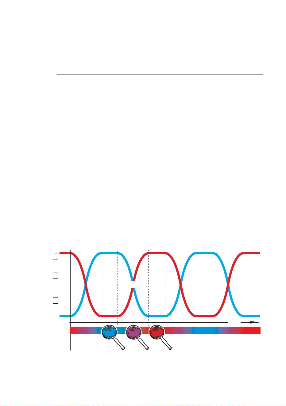
If DIP switch pin 7 is set to ON (crossfading), color fading overlaps. If two or
more colors are active, one color fades in while another is fading out, giving
a color mixing effect. For example, if red and blue are activated and
crossfading is selected, colors will crossfade from red through purple to
blue, then back through purple to red in a continuous cycle (see example).
Red
Blue
100%
Time
Purple
Blue
Blue
100% Blue
100% Blue
0% Red
0% Red
50% Blue
50% Blue
50% Red
50% Red
0% Blue
0% Blue
100% Red
100% Red
Red
0%
50%
Example: crossfading between red and blue

Stand-alone operation 31
Single stand-alone operation
In single stand-alone operation, a luminaire runs its own program
independently of all other luminaires. To do this, the luminaire must be set
as a master.
Activating single stand-alone operation
To activate single stand-alone operation:
1. Set DIP switch pin 10 to ON (switches from DMX to stand-alone mode).
2. Set DIP switch pin 9 to OFF (activates master mode).
3. Set DIP switch pin 8 to OFF (activates stand-alone mode)
4. Program the luminaire using DIP switch pins 1 - 7 (see table on page 29).
Master/Client stand-alone operation
Important! Do not set more than one luminaire on a data link as master, and
do not set a luminaire as master on a data link with a DMX
controller. Doing so may cause damage to the electronics that
is not covered by the product warranty.
In master/client stand-alone operation, one master luminaire transmits a
synchronizing signal to client luminaires over the data link each time it starts
a new action. Client luminaires start their next programmed action when
they receive this signal from the master luminaire. Programs can be
identical on all luminaires, or luminaires can – subject to certain practical
constraints – run programs that are synchronized but not identical.
Note that each luminaire follows the program set on its own DIP switch as
described in the table on page 29.
Note also that colors are always displayed in the order: white → red →
green → blue.
This means for example that if white is activated, it will always be first in the
program. If white is not activated but red is activated, red will be first in the
program.
More sophisticated light shows can be programmed using a DMX controller
(see “DMX-controlled operation” on page 35).
The synchronization signal used by the Cyclo IP65 Directional is identical to
that used in other Cyclo luminaires with the same number of tubes, allowing
these products to be combined in master/client operation on one data link.
However, Cyclos with different numbers of tubes cannot be mixed in master-

32 Cyclo IP65 Directional user manualcient
operation. Consult your Martin Architectural supplier if you need
advice on combining and controlling products.
Identical light shows
Master and client luminaires can be set to behave identically. In this mode,
the master sends synchronizing signals to the clients, and all luminaires run
the same light show. Each client luminaire follows the program set on its
own DIP switch, so for identical operation, all luminaires’ DIP switch settings
must be the same apart from pin 9, which is set to ON for clients and OFF
for the master.
Synchronized non-identical light shows
It is also possible to synchronize changes but program client luminaires to
behave differently from the master. To use this feature effectively, you need
to plan your light show using scenes as building blocks and set the
luminaires’ DIP switches accordingly.
A scene is a change from one output to another. When a luminaire is in client
mode, it starts a scene when it receives a synchronization signal from
the master. The time taken by the scene is determined by the speed setting
of the DIP switch. A client will not respond to new synchronization signals
until its scene is complete.
When crossfading is selected, each color takes up one scene (fade in only).
When blackout fading is selected, each color takes up two scenes (fade in
and fade out). This means that the maximum number of scenes that can be
programmed is twice the number of tubes installed, with all tubes activated
and blackout fading selected.
Each time the master luminaire starts at scene 1, it sends a signal to all the client
luminaires to start at scene 1. This means that if a client luminaire has:
1. Fewer scenes than the master luminaire, it will run these in a cycle until
the master luminaire signals that the program should start from the
beginning again.
2. More scenes than the master, the additional scenes will never run,
because the program will reset to the first scene when the master starts
its program from the beginning.
Here is an example of what will happen when a client luminaire has fewer
scenes than the master luminaire:
Luminaire setting Scene pattern
Master with 6 scenes 123456 123456 123456...
Client with 4 scenes 123412 123412 123412...
Stand-alone operation 33
Program examples
The following examples of programs show how an individual luminaire’s
program is made up of scenes.
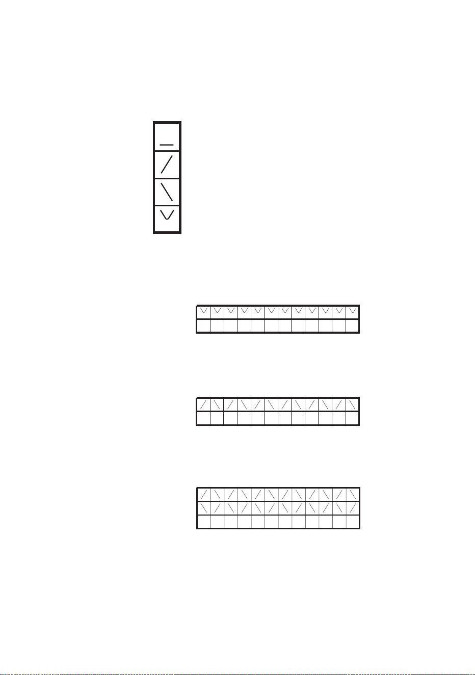
The following symbols are used in program diagrams:
Example 1
DIP switch 7 is set to ON (crossfading) and only red is activated:
Example 2
DIP switch 7 is set to OFF (blackout fading) and only red is activated:
Example 3
DIP switch 7 is set to ON (crossfading) and red and blue are activated:
Tube turned fully off
Fade in
Fade out
Fade to 50% and back to 100% in one scene
(applies when only one color is active and
crossfading is selected)
1 1 11 111 1 111 1
Red
Scene
21 21 21 21 21 21
Red
Scene
1 2 21 211 2 21 21
Red
Blue
Scene
34 Cyclo IP65 Directional user manual
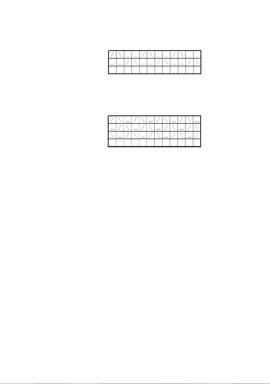
Example 4
DIP switch 7 is set to OFF (blackout fading) and red and blue are activated:
Example 5
To achieve a rainbow effect, activate red, green and blue tubes and set DIP
switch pin 7 to ON (crossfading).
Activating master/client stand-alone operation
To activate master/client stand-alone operation:
1. Isolate all luminaires from power.
2. Set all luminaires as clients and enable stand-alone mode by setting DIP
switch pins 9 and 10 to ON and pin 8 to OFF.
3. Decide which luminaire to use as master and set this luminaire’s DIP
switch pin 9 to OFF. Note that any luminaire can be set as master, but
you will obtain the most reliable data signal by either setting the first
luminaire on the link as master or using 120 Ohm resistors to terminate
the data link (see “Connecting to control data” on page 22) at both ends.
4. When power is applied, client luminaires will go to the next scene in their
program each time the master goes to its next scene. Client luminaires
will also start scene 1 of their programs each time the master starts
scene 1 of its program.
21 43 421 3 421 3
Red
Blue
Scene
1 2 3 1 2 3 1 2 3 1 2 3
Red
Green
Blue
Scene

DMX-controlled operation 35
DMX-controlled operation
DANGER! Read “Safety information” on page 3 before attempting to
operate this product!
Cyclo IP65 Directional DMX models may be operated with any lighting
control device that is compatible with the USITT DMX (1990) standard.
For details of connecting luminaires on a data link to a DMX controller, see
“Linking luminaires for DMX and synchronized operation” on page 21.
For details of setting up luminaires for DMX control, see “Configuring
luminaires for DMX or stand-alone operation” on page 23
DMX control functions
The Cyclo IP65 Directional’s advanced fluorescent tubes can be dimmed
from maximum output right down to zero using one channel per tube on a
DMX controller. This allows a wide range of color shades with variable
intensity to be obtained using additive color mixing. On 04 models the color
temperature of white light can also be fine-tuned.
Depending on the functions available on the controller, sophisticated light
shows on the Cyclo IP65 Directional can be programmed over time,
allowing constantly and rapidly shifting color mixes, or color displays which
change slowly according to the time of day, or even year, for example. See
the controller’s manual for details.
Your Martin Architectural supplier can advise about available controllers and
control options.

36 Cyclo IP65 Directional user manual
Service
DANGER! Read “Safety information” on page 3 before attempting to
service this product!
With long-life fluorescent tubes and no moving parts, the Cyclo IP65
Directional is almost service-free, but this section describes the minimum of
periodic maintenance required.
Refer any service operation not described in this manual to an authorized
Martin service agent.
Cleaning
Use a damp cloth or soft brush soaked in a solution of water and a mild
detergent cleaner such as auto shampoo to clean luminaires. Do not use
abrasive, acidic or caustic cleaning products, or you will damage the
luminaires’ anodized finish.
Do not use a high pressure water-jet for cleaning: IP65 luminaires are
protected against water projections and low-pressure water jets only.
Tube replacement
To replace the tubes in the Cyclo IP65 Directional:
1. Isolate the luminaire from power and ensure that power cannot be
reapplied, even accidentally.
2. Loosen the front cover release screws, lift up the release flap and open
the front cover as described in “Orientation and adjustment” on page 12.
3. See Figure
13. Remove
the reflector
by lifting it out
of the tube
module
housing.
4. In 04 models,
remove the
white tube by
holding the
metal caps at
both ends of
the tube,
rotating the
tube approx.
1/4 turn in
either direction, and sliding the tube’s terminal pins out of their
sockets. Support the tube at both ends as it is released.
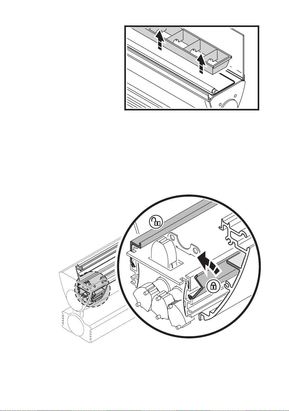
5. See Figure 14. To release the diffuser, push the locking bars from
position B in towards the center of the luminaire until they are in
position A. Lift the diffuser out of the luminaire.
6. The red, green and blue tubes are installed close together. To
remove, press with one finger on the metal caps at both ends of each
tube and rotate to release from the sockets.
Figure 13: Removing the reflector
A
A
B
B
Figure 14: Removing the diffuser

7. When installing new tubes, line them up so that the manufacturer’s
markings on all tubes are at the same end of the luminaire. Tube
positions are labelled R for red, G for green and B for blue. Slide
each tube’s terminal pins fully into their sockets and rotate the tube
approx. 1/4 turn in either direction to engage the pins. Check that
tubes are held securely.
8. Reinstall the diffuser, reflector, white tube (in 04 models) and front
cover before reapplying power.
Tube positions
The burning positions of fluorescent tubes affect their warm-up times,
operating temperature, light output and tube life. For optimum results:
• Install tubes so that the manufacturer’s markings are all at the same
end of the luminaire.
• If the luminaire is installed in a vertical position or at an angle from the
horizontal, locate the ends of the tubes that carry the manufacturer’s
markings at the lower end of the luminaire. However, in a cold
environment, i.e. where temperatures are generally around or below
freezing point, locate the markings at the upper end of the luminaire).
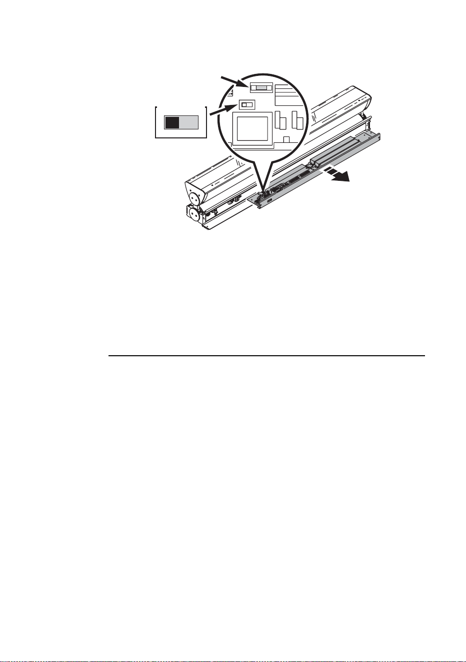
Main fuse replacement
The main fuse is located on the PCB in the ballast tray. See page 43 in
the Specifications section for details of fuse types and ratings. Never
replace a fuse with one of a different type or rating.
To replace the fuse:
1. Isolate the luminaire from power and ensure that power cannot be
reapplied accidentally.
2. Open the connections compartment cover as described in “Access to
connections compartment” on page 10.
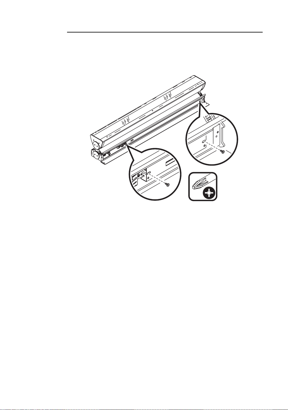
3. See Figure 15. Undo the two retaining screws from the ballast tray
and slide the tray out of the housing.
Figure 15: Removing the PCB
4. See Figure 16. Replace the main fuse on the PCB with one of the
same type and rating.
5. Reinstall all covers before reapplying power.
If a fuse blows repeatedly, refer to your Martin Architectural supplier for
service.
Voltage setting
See Figure 16. The voltage switch on the PCB is factory-set to match
100-120 or 200-240 V nominal AC power at 50 or 60 Hz.
Important! Do not change the voltage setting without first
consulting your Martin Architectural supplier.
230V 115V
230V 115V
Figure 16: Main fuse
Main fuse

Troubleshooting
Problem Probable cause(s) Remedy
No response from luminaire
when power is applied.
No power to luminaire. Check power connections.
Ground fault protection circuit
breaker (RCD) has tripped.
Reset RCD. If problem
persists, have an electrician
replace the RCD or reduce the
number of luminaires powered
via one RCD.
If running in stand-alone
mode, DIP switch pin 8 is set
to ON.
Set DIP switch pin 8 to OFF to
allow stand-alone operation.
Luminaires do not respond
correctly to DMX control.
Controller not connected. Check DMX data link. Inspect
connections and test cables.
Repair or replace as
necessary.
Incorrect DMX addressing. Check address setting on
luminaire and controller.
Data link not terminated. Connect 120 Ohm termination
resistor across data link +
(hot) and - (cold) in parallel
with last luminaire on link.
Two devices transmitting on
link.
Check that all luminaires are
set as
clients (DIP switch pin 9
ON).
Defective luminaire. Bypass luminaires one at a
time until normal operation is
regained to identify faulty
luminaire.
Have faulty luminaire tested
and repaired by Martin service
technician.
Luminaires do not behave
correctly in master/
client mo
de
Tw
o luminaires transmitting on
link.
Check that only one luminaire
is set to operate as master.
Defective luminaire. Bypass luminaires one at a
time until normal operation is
regained to identify faulty
luminaire.
Have faulty luminaire tested
and repaired by Martin service
technician.
Poor quality light output and/or
color rendering.
Tube or tubes not burnt in. Run tubes at 100% intensity
for 100 hours to burn in.
Tube defective. Disconnect luminaire and
replace tube.
Table 4: Troubleshooting

DMX protocols
Cyclo 04 IP65 Directional
Cyclo 03 IP65 Directional
Channel Value Percent Function
1
0-2
3-252
253-255
0
1 - 99
100
White intensity
Tube off
Intensity 1
→100%
Intensity 100%
2
0-2
3-252
253-255
0
1 - 99
100
Red intensity
Tube off
Intensity 1
→100%
Intensity 100%
3
0-2
3-252
253-255
0
1 - 99
100
Green intensity
Tube off
Intensity 1
→100%
Intensity 100%
4
0-2
3-252
253-255
0
1 - 99
100
Blue intensity
Tube off
Intensity 1
→100%
Intensity 100%
Table 5: DMX protocol, Cyclo 04 IP65 Directional
Channel Value Percent Function
1
0-2
3-252
253-255
0
1 - 99
100
Red intensity
Tube off
Intensity 1
→100%
Intensity 100%
2
0-2
3-252
253-255
0
1 - 99
100
Green intensity
Tube off
Intensity 1
→100%
Intensity 100%
3
0-2
3-252
253-255
0
1 - 99
100
Blue intensity
Tube off
Intensity 1
→100%
Intensity 100%
Table 6: DMX protocol, Cyclo 03 IP65 Directional

Cyclo IP65 Directional
specifications
Physical
L x W x H . . . . . . . . . . . . . . . . . 1257 x 149 x 230 mm (49.5 x 5.9 x 9.1 in.)
Weight . . . . . . . . . . . . . . . . . . . . . . . . . . . . . . . . . . . . . . . . 22 kg (48.5 lbs)
Lamp
Type . . . . . . . . . . . . . . . . . . . . . . . . . . . . . . . . . . . . . . T5 fluorescent tubes
Approved lamps . . . . . . . . . . . . . . . . . . . . . . . . . . . . . Osram FQ 54 W HO
Average tube life . . . . . . . . . . . . . . . . . . . . . . . . . . . . . . . . . . 20 000 hours
Socket . . . . . . . . . . . . . . . . . . . . . . . . . . . . . . . . . . . . . . . . . . . . . . . . . . G5
Dynamic effects
Color mixing . . . . . . . . . . . . . . . . . . .RGB (03 models) RGBW (04 models)
Red. . . . . . . . . . . . . . . . . . . . . . . . . . . . . . . . . . . . . . . . . . . . . . . . 0 - 100%
Green . . . . . . . . . . . . . . . . . . . . . . . . . . . . . . . . . . . . . . . . . . . . . . 0 - 100%
Blue . . . . . . . . . . . . . . . . . . . . . . . . . . . . . . . . . . . . . . . . . . . . . . . 0 - 100%
Cool white (4000 K) . . . . . . . . . . . . . . . . . . . . . . . . . 0 - 100% (04 models)
Control and programming
Control options . . . . . . . . .DMX, stand-alone, synchronized (master/client)
Number of DMX channels . . . . . . . . . . . . . . .3 (03 models), 4 (04 models)
DMX address setting . . . . . . . . . . . . . . . . . . . . . . . . . . . . . . . . . DIP switch
Stand-alone and master/client programming . . . . . . . . . . . . . . . DIP switch
Protocol . . . . . . . . . . . . . . . . . . . . . . . . . . . . . . . . . . USITT DMX512/1990
Receiver . . . . . . . . . . . . . . . . . . . . . . . . . . . . . . . . . . . . . . . . . . . . . RS-485
Construction
Housing . . . . . . . . . . . . . . . . . . . . . . . . . . . . Aluminum and stainless steel
Finish . . . . . . . . . . . . . . . . . . . . . . . . . . . . . . . . . . . . . . . . . Clear anodized
Front cover . . . . . . . . . . . . . . . . . . . . . . . . . . . . . . . . . . . . Toughened glass
Reflectors . . . . . . . . . . . . . . . . . . . . . . . . . .High specular 99.9% aluminum
Protection factor . . . . . . . . . . . . . . . . . . . . . . . . . . . . . . . . . . . . . . . . . . IP65
Installation
Orientation . . . . . . . . . . . . . . . . . . . . . . . . . . . . . . . . . . . . . . . . . . . . . . Any
Minimum free space around luminaire . . . . . . . . . . . . . . . .25 mm (1 inch)
Connections
Power cable entry. . . . . . . . . . . . . . . . . . . . . . . . . . . . . . . IP68 cable gland
Power connection. . . . . . . . . . . . . . . . . . . . . . . . Quick connector terminals
Data cable entry . . . . . . . . . . . . . . . . . . . . . . . . . . . . . . . . IP68 cable gland
Data connection . . . . . . . . . . . . . . . . . . . . . . . . . . . . . . . . . Screw terminals

Electrical
AC power . . . . . . . . . . . . . . . . . . . . 100-120/200-240 V nominal, 50/60 Hz
Main fuse, 03, 120 V model . . . . . . . . . . . . . . . . . . . . . . . 2 AT (slow blow)
Main fuse, 04, 120 V model . . . . . . . . . . . . . . . . . . . . . . 2.5 AT (slow blow)
Main fuse, 03, 230 V model . . . . . . . . . . . . . . . . . . . . . . . 1 AT (slow blow)
Main fuse, 04, 230 V model . . . . . . . . . . . . . . . . . . . . . . . 2 AT (slow blow)
Typical power and current
Cyclo IP65 03 Directional, 120 V model
100 V, 60 Hz. . . . . . . . . . . . . . . . . . . . . . . . . . . . . . . . . . . . . . 163 W, 1.6 A
120 V, 60 Hz. . . . . . . . . . . . . . . . . . . . . . . . . . . . . . . . . . . . . . 180 W, 1.5 A
Cyclo IP65 03 Directional, 230 V model
208 V, 60 Hz. . . . . . . . . . . . . . . . . . . . . . . . . . . . . . . . . . . . . . 180 W, 0.9 A
230 V, 50 Hz. . . . . . . . . . . . . . . . . . . . . . . . . . . . . . . . . . . . . . 181 W, 0.8 A
240 V, 50 Hz. . . . . . . . . . . . . . . . . . . . . . . . . . . . . . . . . . . . . . 179 W, 0.8 A
Cyclo IP65 04 Directional, 120 V model
100 V, 60 Hz. . . . . . . . . . . . . . . . . . . . . . . . . . . . . . . . . . . . . . 219 W, 2.2 A
120 V, 60 Hz. . . . . . . . . . . . . . . . . . . . . . . . . . . . . . . . . . . . . . 236 W, 2.0 A
Cyclo IP65 04 Directional, 230 V model
208 V, 60 Hz. . . . . . . . . . . . . . . . . . . . . . . . . . . . . . . . . . . . . . 235 W, 1.2 A
230 V, 50 Hz. . . . . . . . . . . . . . . . . . . . . . . . . . . . . . . . . . . . . . 234 W, 1.1 A
240 V, 50 Hz. . . . . . . . . . . . . . . . . . . . . . . . . . . . . . . . . . . . . . 231 W, 1.0 A
Measurements made at nominal voltage. Allow for a deviation of +/- 10%.
Thermal
Maximum ambient temperature (T
a
). . . . . . . . . . . . . . . . . . . 40° C (104° F)
Minimum ambient temperature (starting from and dimming
at 1% output possible when permanently powered). . . . . . -20°C (-4°F)
Cooling . . . . . . . . . . . . . . . . . . . . . . . . . . . . . . . . . . . . . . . . . . . .Convection
Total heat dissipation (calculated, +/- 10%):. . . . . 615 BTU/hr. (03 models)
. . . . . . . . 805 BTU/hr. (04 models)
Approvals
US Safety . . . . . . . . . . . . . . . . . . . . . . UL 1573
Canadian Safety . . . . . . . . CSA C22.2 No. 166
European safety . . . EN 60598-1, EN 60598-2
European EMC . . . . . . EN 60555-3. EN 55015

Included items
Osram FQ 54 W/60 HO red T5 tube
Osram FQ 54 W/66 HO green T5 tube
Osram FQ 54 W/67 HO blue T5 tube
Osram FQ 54 W/840 HO cool daylight white (4000 K) T5 tube (04 models)
Two M25 cable glands, IP68, metal, cable Ø 7 - 15 mm (0.28 - 0.6 in.)
Two M16 cable glands, IP68, metal, cable Ø 5 - 12 mm (0.2 - 0.45 in.)
M25 blanking plug, metal
M16 blanking plug, metal
Surface-mounting bracket
User manual
Accessories
DMX termination resistor, 120 Ohm . . . . . . . . . . . . . . . . . . . P/N 04150308
Osram T5 FQ 54 W/827 HO 2700 K warm white
tube (04 model) . . . . . . . . . . . . . . . . . . . . . . . . . . . . . . . . P/N 97020009
Osram T5 FQ 54 W/865 HO 6500 K daylight white
tube (04 model) . . . . . . . . . . . . . . . . . . . . . . . . . . . . . . . . P/N 97020011
Spare parts
Osram T5 FQ 54 W/60 HO red tube . . . . . . . . . . . . . . . . . . P/N 97020006
Osram T5 FQ 54 W/66 HO green tube . . . . . . . . . . . . . . . . P/N 97020007
Osram T5 FQ 54 W/67 HO blue tube. . . . . . . . . . . . . . . . . . P/N 97020008
Osram T5 FQ 54 W/840 HO 4000 K cool white
tube (04 model) . . . . . . . . . . . . . . . . . . . . . . . . . . . . . . . . P/N 97020010
Ordering information
Cyclo IP65 03 Directional, 54 W tubes, 120 V . . . . . . . . . . . P/N 90566810
Cyclo IP65 03 Directional, 54 W tubes, 230 V . . . . . . . . . . . P/N 90566010
Cyclo IP65 04 Directional, 54 W tubes, 120 V . . . . . . . . . . . P/N 90567810
Cyclo IP65 04 Directional, 54 W tubes, 230 V . . . . . . . . . . . P/N 90567010
Specifications subject to change without notice.

Disposing of this product
Martin Architectural
®
products are supplied in compliance with
Directive 2002/96/EC of the European Parliament and of the
Council of the European Union on WEEE (Waste Electrical and
Electronic Equipment), as amended by Directive 2003/108/EC,
where applicable.
Help preserve the environment! Ensure that this product is
recycled at the end of its life. Your supplier can give details of
local arrangements for the disposal of Martin
®
products.

www.martin-architectural.com • Olof Palmes Allé 18 • 8200 Aarhus N • Denmark
Tel: +45 8740 0000 •
Fax +45 8740 0010
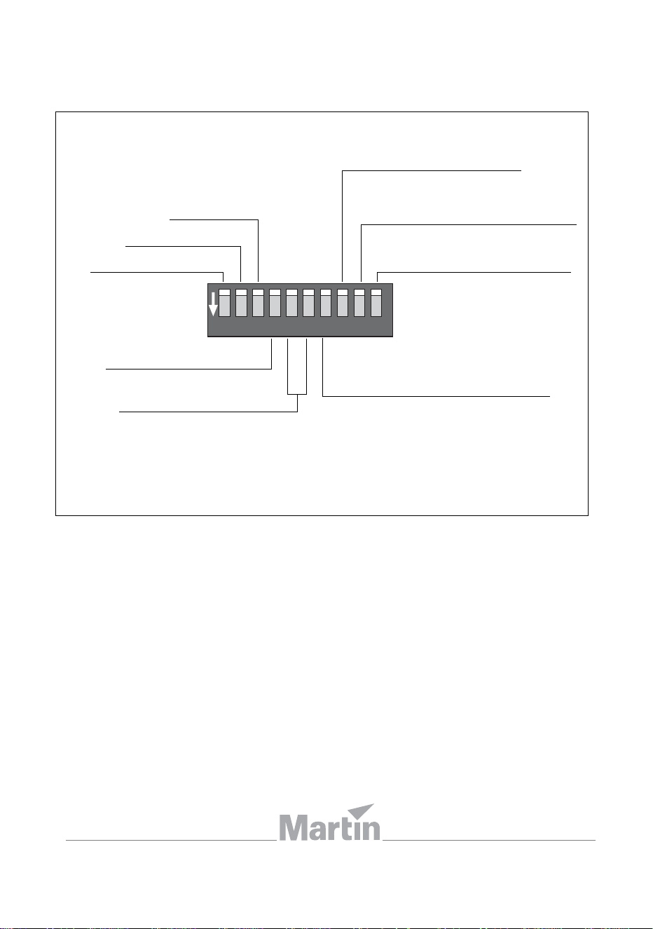
1 2 3 4 5 6 7 8 910
ON
1. Tube 1
2. Tube 2
3. T
ube 3
4. Tube 4 (04 models)
5/6. Program speed
8. ON = Deactivate stand-alone OFF
= Activate stand-alone
9. ON = Stand-alone client
OFF = Stand-alone master/single
10. ON = Stand-alone
OFF = DMX
7. ON = Crossfading
OFF = Blackout fading
Quick reference
Cyclo IP65 Directional stand-alone operation
DIP switch settings
