THIS INSTRUCTION BOOKLET CONTAINS IMPORTANT SAFETY INFORMATION.
PLEASE READ AND KEEP FOR FUTURE REFERENCE.
Date: 2024-06-12 Rev. 0001-A
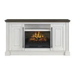
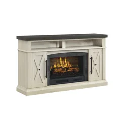
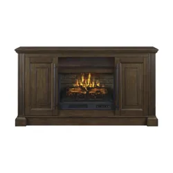
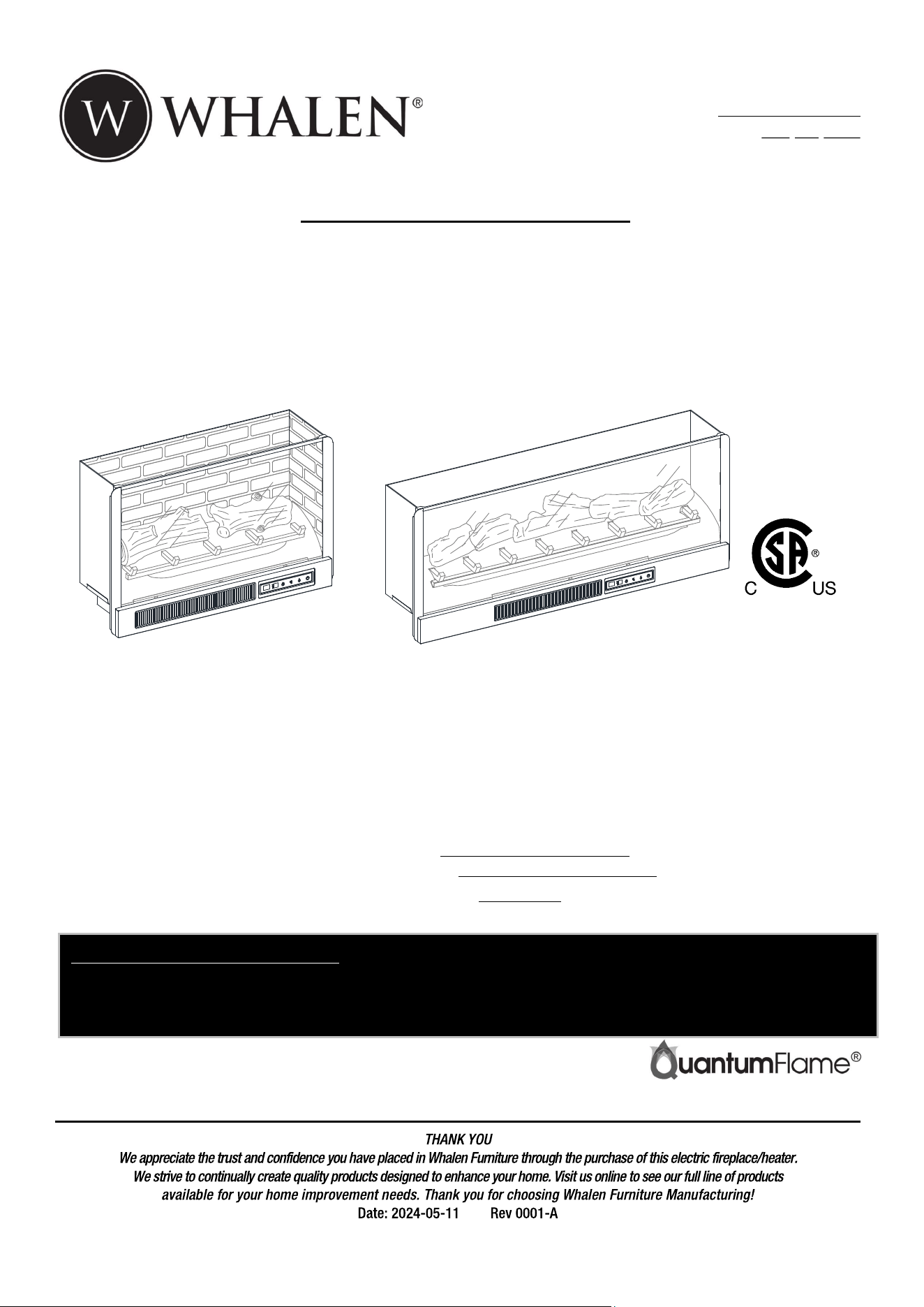
Hutchinson 65” Fireplace Console
Model # MNFP65MR26HLAWT
# MNFP65MR26HLADK
ADULT ASSEMBLY REQUIRED
If you have any questions regarding assembly or if parts are missing, DO NOT return this item to the
store where it was purchased. Please call our toll-free customer service number and have your
instructions and parts list ready to provide the model name, part name or factory number:
1-866-942-5362
Pacific Standard Time: 8:30 a.m. - 4:30 p.m., Monday - Friday
Or visit our web site 24 hours a day, 7 days a week for product assistance at
www.whalenfurniture.com
Or e-mail your request to parts@whalenfurniture.com
LOT NUMBER:
DATE PURCHASE
D
:
/
/
OR
2
IMPORTANT
Before you begin: Open, identify and count all parts prior to assembly. Lay out parts on a flat and
non-abrasive surface. You will need the parts identified on page 3, 4 and 5 of this instruction manuals.
NOTE: IT IS VERY IMPORTANT TO USE GLUE WITH THE DOWELS. EXCESS GLUE CAN BE
WIPED OFF WITH A DAMP CLOTH.
Insert dowel at least halfway by tapping lightly with a rubber mallet (not included), IF NECESSARY.
CAM LOCK SYSTEM OPERATION
HOW THE KNOCK DOWN (KD) ASSEMBLY SYSTEM WORKS
1. Screw the Cam Bolt into the pre-drilled small holes on the panel. Connect both panels together; making sure
the Cam Bolt goes into the pre-drilled hole at the end of the panel with the Cam Lock.
2. Insert the Cam Lock into the pre-drilled large hole in the panel. Make sure the arrow on the Cam Lock is
pointed towards the Cam Bolt.
3. Once the Cam Bolt is connected inside the Cam Lock, take a Phillips screwdriver (not included) and
tighten the Cam Lock clockwise.
4. Stick the paper cover on the Cam Locks to conceal the cam.
You are now ready to assemble the KD unit.
How to adjust the European adjustable hinges on doors
Shipping may cause doors to go out of alignment. If you find that the doors need to be adjusted slightly,
turn the appropriate screw, as illustrated.
1. TO ADJUST DOOR FORWARD OR BACKWARD.
2. TO ADJUST DOOR TO RIGHT OR TO LEFT.
3. TO ADJUST DOOR UP OR DOWN.
1
2
3
4
FINAL
1
3
G
L
UE
3
Parts and Hardware List
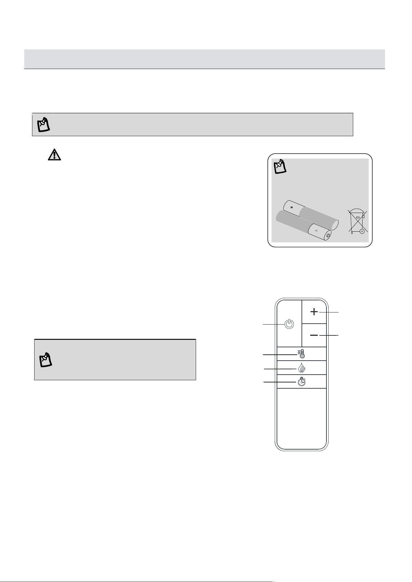
Please read completely through the instructions and verify that all listed parts and hardware are present
before beginning assembly.
A- Heater B- Left Upright Arm C- Right Upright Arm
(Qty. 1) (Qty. 1) (Qty. 1)
D- Connector Strap E- Ember Bed F- Left Log
(Qty. 1) (Qty. 1) (Qty. 1)
G- Right Log H- Wall Panel I- Glass Screen
(Qty. 1) (Qty. 1) (Qty. 1)
J- Remote Control with Battery K- Top Panel L- Top Stretcher
(Qty. 1) (Qty. 1) (Qty. 1)
M- Bottom Panel N- Front Skirting O- Rear Skirting
(Qty. 1) (Qty. 1) (Qty. 1)
P- Side Skirting Q- Firebox Holder R- Bottom Middle Stretcher
(Qty. 2) (Qty. 1) (Qty. 1)
4
Parts and Hardware List
Please read completely through the instructions and verify that all listed parts and hardware are present
before beginning assembly.
S- Left Side Panel T- Left Partition U- Right Partition
(Qty. 1) (Qty. 1) (Qty. 1)
V- Right Side Panel W- Media Shelf X- Door
(Qty. 1) (Qty. 1) (Qty. 2)
Y- Wood Door Panel Z- Adjustable Shelf A1- Middle Back Panel
(Qty. 2) (Qty. 4) (Qty. 1)
B1- Side Back Panel C1- Firebox Long Support D1- Firebox Short Support
(Qty. 2) (Qty. 1) (Qty. 2)
E1- Door Hinge F1- Handle
(Qty. 4) (Qty. 2)
5
Parts and Hardware List
Please read completely through the instructions and verify that all listed parts and hardware are present
before beginning assembly.
(1) M4 x 10 mm Insert Screw (2) Cam Lock (3) Cam Bolt
(Qty. 10+1 extra) (Qty. 38+1 extra) (Qty. 38+1 extra)
(4) M8 x 30 mm Wood Dowel (5) M3.5 x 15 mm Washer Head Screw (6) M3.5 x 12 mm Screw
(Qty. 42+2 extra) (Qty. 40+2 extra) (Qty. 4+1 extra)
(7) Mending Plate (8) M4 x 50 mm Pan Head Screw (9) M4 x 15 mm Nickel Screw
(Qty. 2) (Qty. 13+1 extra) (Qty. 24+1 extra)
(10) 5/32” x 22 mm Bolt (11) M4 x 12 mm Pan Head Screw (12) L-Shaped Metal Bracket
(Qty. 4+1 extra) (Qty. 8+1 extra) (Qty. 2)
(13) Shelf Support (14) Acrylic Stopper (15) Paper Cover (16) Rubber Bumper
(Qty. 16+1 extra) (Qty. 1) (Qty. 12+1 extra) (Qty. 4+1 extra)
Glue Touch-up Pen Tipping Restraint Hardware Kit (Qty. 2)
(Qty. 2) (Qty. 1) (Included in plastic bag)
Tools required (not included): Phillips screwdriver, stud finder, pencil, tape measure, power drill
and 1/8” drill bit, rubber mallet and pliers.
6
S
V
L
4
4
4
4
4
4
Assembly Instructions
1. Unpack the unit and confirm that you have all the hardware and required parts. Assemble the unit on a
carpeted floor or the empty carton to avoid any scratch.
2. Securely screw 14 Cam Bolts (3) into the designated small holes on the Top Panel (K) and Side Panels
(S and V) with a Phillips screwdriver.
NOTE: Screw-in cam bolts must be screwed down flush. DO NOT overtighten the cam bolts.
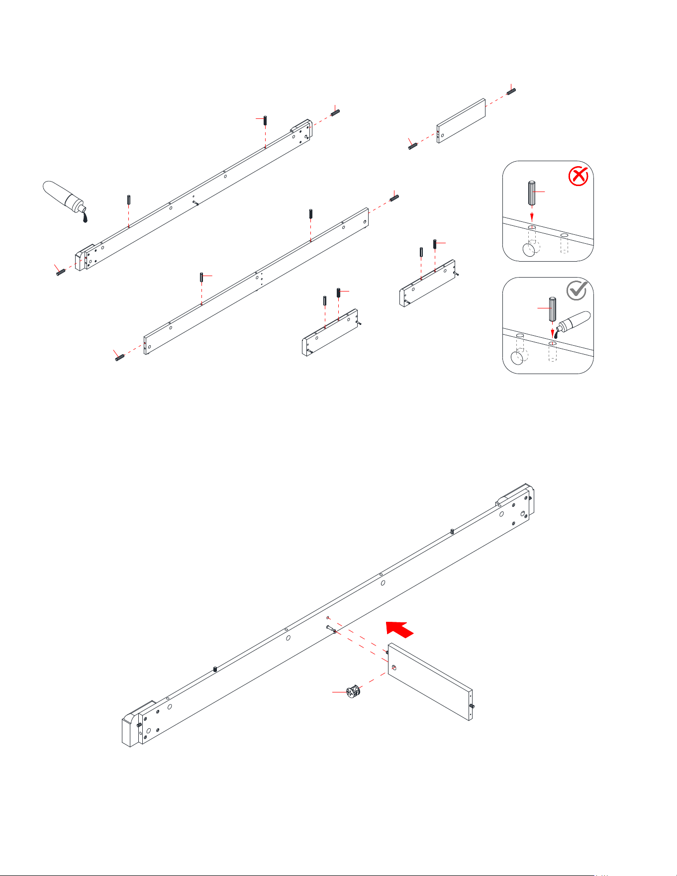
3. Glue 10 Wood Dowels (4) into the designated holes on the Side Panels (S and V) and Top Stretcher (L).
NOTE: It is very important to use a small amount of glue on both ends of dowels and wipe away the
excess glue immediately with a damp cloth.
K
S
V
3
4
4
Correct
Incorrect
7
V
S
L
2
Assembly Instructions
4. Orient and attach the Top Stretcher (L) between the Side Panels (S and V) by engaging and tightening 2
Cam Locks (2) with a Phillips Screwdriver. (Refer to page 2 on Cam Lock system operation
supplement).
5. Ask for assistance to position the Top Panel (K) onto the Top Stretcher (L) and the Side Panels (S and
V) properly and fasten them into place with 8 Cam Locks (2).
The cam lock housings
face inward.
S
V
L
K
2
The wood dowels face upward.
8
Assembly Instructions
6. Securely screw 4 Cam Bolts (3) into the designated small holes on the Partitions (T and U) with a
Phillips screwdriver.
7. Glue 12 Wood Dowels (4) into the designated holes on both Partitions (T and U) and the Media Shelf
(W).
T
U
3
T
U
W
4
4
4
4
4
4
4
4
Correct
Incorrect
9
U
T
W
2
Assembly Instructions
8. Orient and attach the Media Shelf (W) between the Partitions (T and U) by engaging and tightening 4
Cam Locks (2).
9. Align and attach the previous assembly to the Top Panel (K) by engaging and tightening 4 Cam Locks
(2).
U
T
K
2
The cam lock housings
face inward.
The molding is located at the front.

10
Assembly Instructions
10. Securely screw 11 Cam Bolts (3) into the designated small holes on the Bottom Panel (M) with a
Phillips screwdriver.
11. Securely screw 5 Cam Bolts (3) into the designated small holes on the Front Skirting(N) and Side
Skirtings (P) with a Phillips screwdriver.
M
3
3
N
P
P
11
Assembly Instructions
12. Glue 14 Wood Dowels (4) into the designated holes on the Skirting Boards (N, O and P) and Bottom
Middle Stretcher (R).
13. Align and attach the Bottom Middle Stretcher (R) to the Front Skirting (N) by engaging one Cam Lock
(2).
4
4
R
N
2
Correct
Incorrect
4
4
4
4
4
4
4
O
R
N
4
4
P
P
4

12
Assembly Instructions
14. Orient and attach the Rear Skirting (O) to the Bottom Middle Stretcher (R) by inserting two 50 mm Pan
Head Screws (8) through the counter-sunk holes on the Rear Skirting (O) and securely screw into place.
15. Align and attach the Side Skirtings (P) to the Front and Rear Skirtings (N and O) by engaging 4 Cam
Locks (2).
R
O
N
8
The wood dowels face upward.
N
O
P
P
2
13
Assembly Instructions
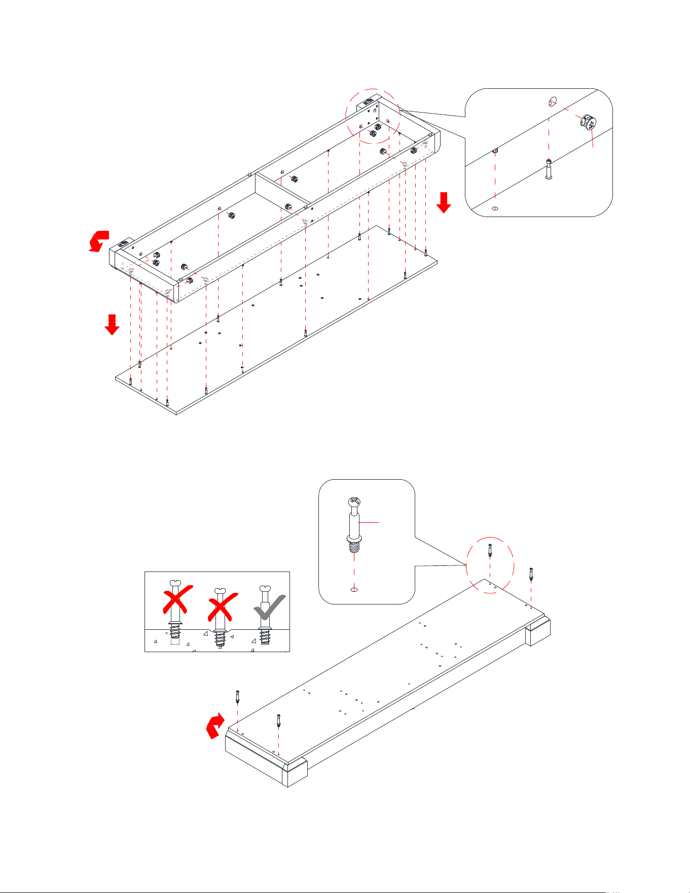
16. Align and attach the previous assembly to the Bottom Panel (M) by engaging 11 Cam Locks (2).
17. Securely screw 4 Cam Bolts (3) into the designated small holes on the top of the Bottom Panel (M)
using a Phillips screwdriver.
M
180°
3
180°
N
O
P
P
M
2
14
Assembly Instructions
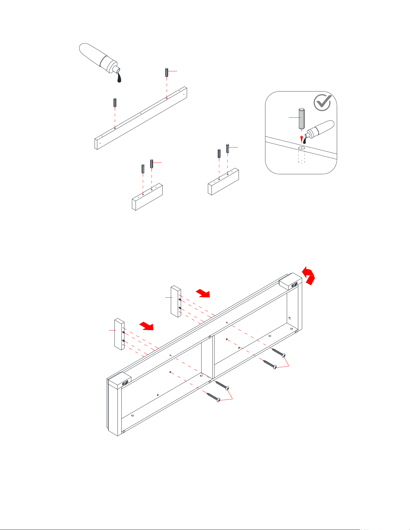
18. Glue 6 Wood Dowels (4) into the inner holes on the Firebox Supports (C1 and D1) as shown.
19. Align the wood dowels inserted under the Firebox Short Supports (D1) with the holes on the Bottom
Panel (M), and then press them together. Insert four 50 mm Pan Head Screws (8) through the mounting
holes on the Bottom Panel (M) and securely screw into the Firebox Short Supports (D1).
C1
D1
D1
4
4
4
4
M
D1
D1
8
8
90°
Correct
15
Assembly Instructions
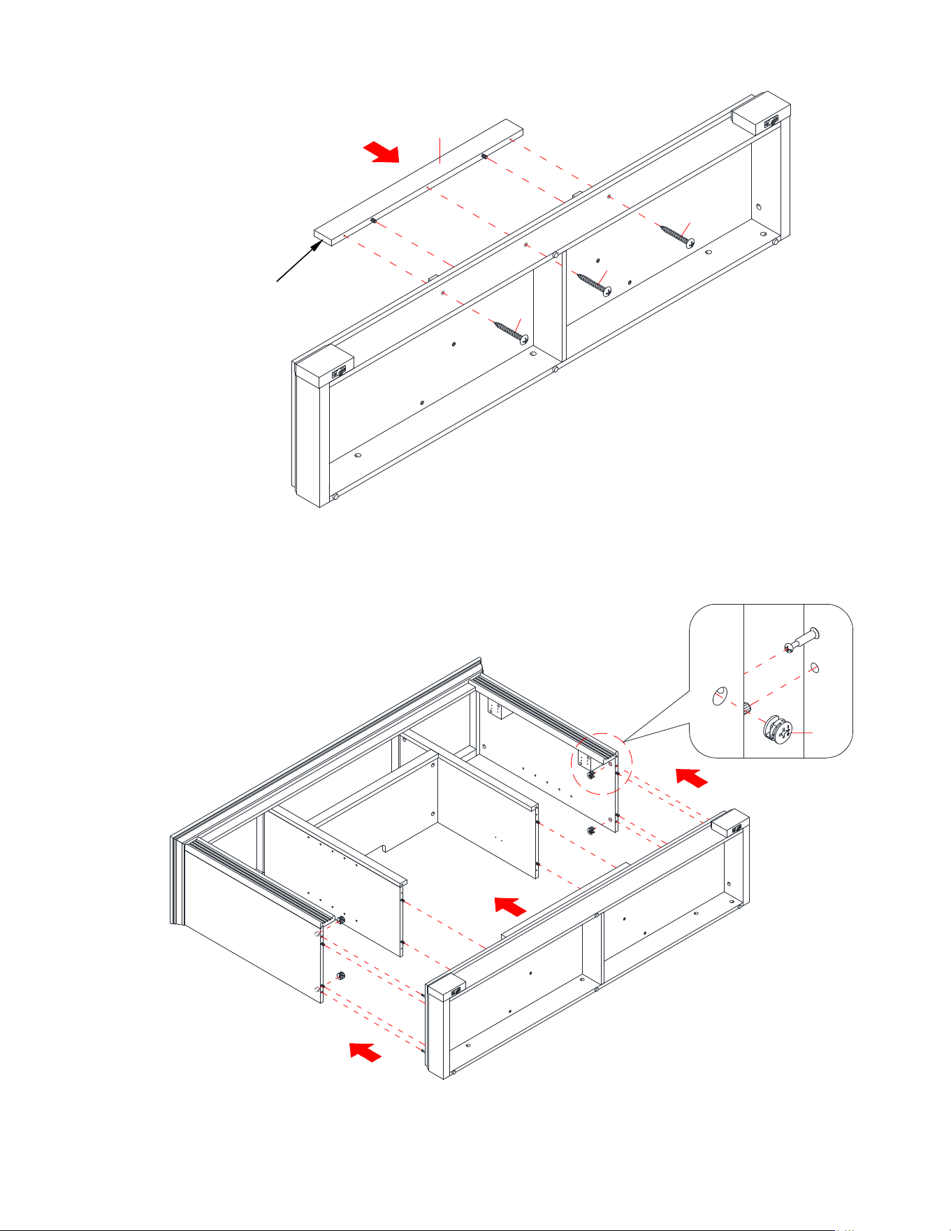
20. Orient and attached the Firebox Long Support (C1) to the Bottom Panel (M).
21. Insert three 50 mm Pan Head Screws (8) through the mounting holes on the Bottom Panel (M) and
securely screw into the Firebox Long Support (C1).
22. Align and attach the Bottom Panel (M) to the assembled Side Panels (S and V) by engaging and
tightening 4 Cam Locks (2) with a Phillips screwdriver.
C1
8
8
8
M
U
T
S
V
2
The mounting holes face inward.
16
Assembly Instructions
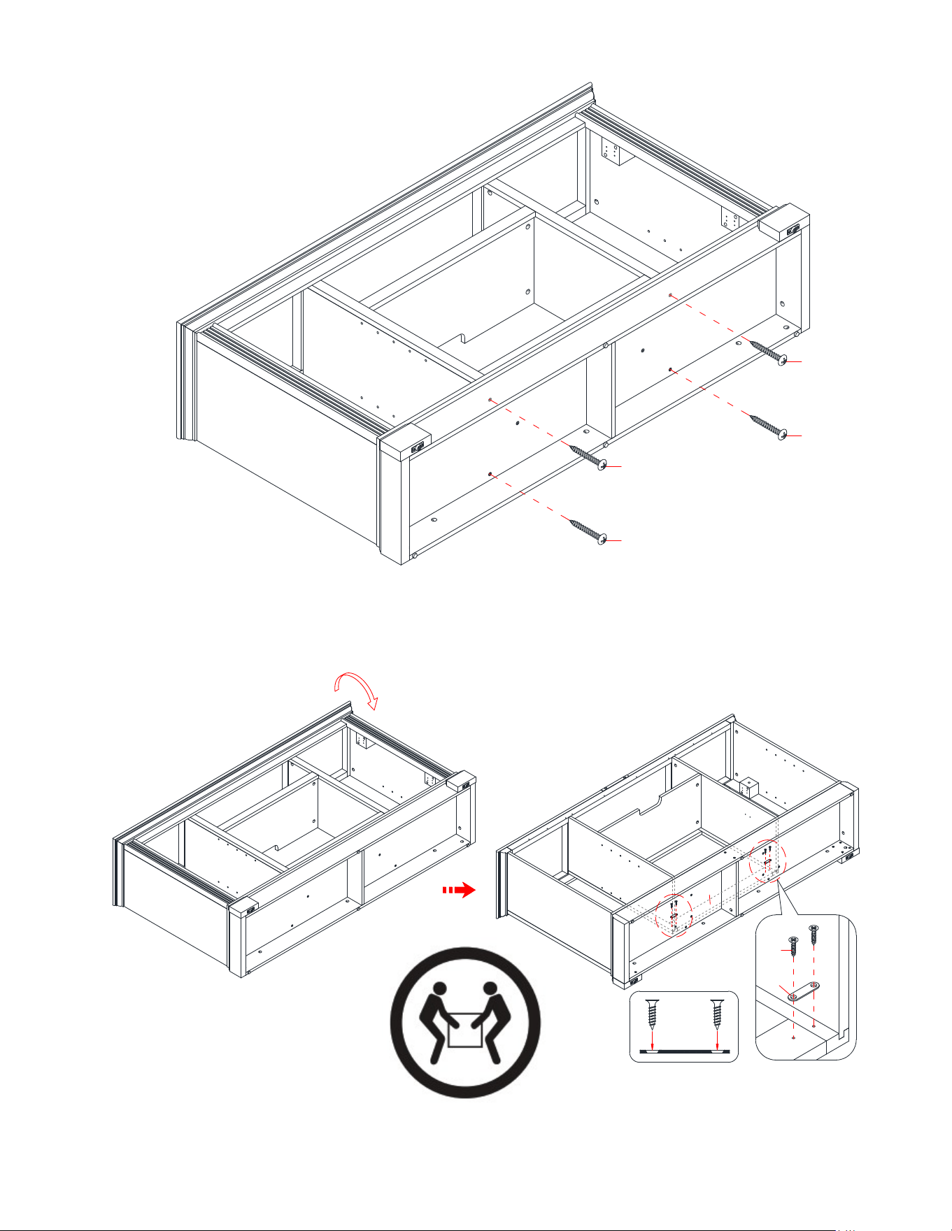
23. Insert four 50 mm Pan Head Screws (8) through the mounting holes on the Bottom Panel (M) and
securely screw into the Partitions (T and U).
24. Ask for assistance to flip around the previous assembly at its front edges.
25. Using the pilot holes as a guide, attach two Mending Plates (7) at the joints where the Firebox Long
Support (C1) meets the Partitions (T and U), with two 12 mm Screws (6) per plate.
U
T
M
8
8
8
8
M
M
C1
U
T
U
T
180°
6
7
17
Assembly Instructions
26. Now, go back and securely tighten all the cam locks and screws. Make sure that all the parts are tight
and there are no gaps between the parts. This will help keep the unit square.
27. Pick up the Middle Back Panel (A1) and align the pre-drilled holes against the upper long edge of the
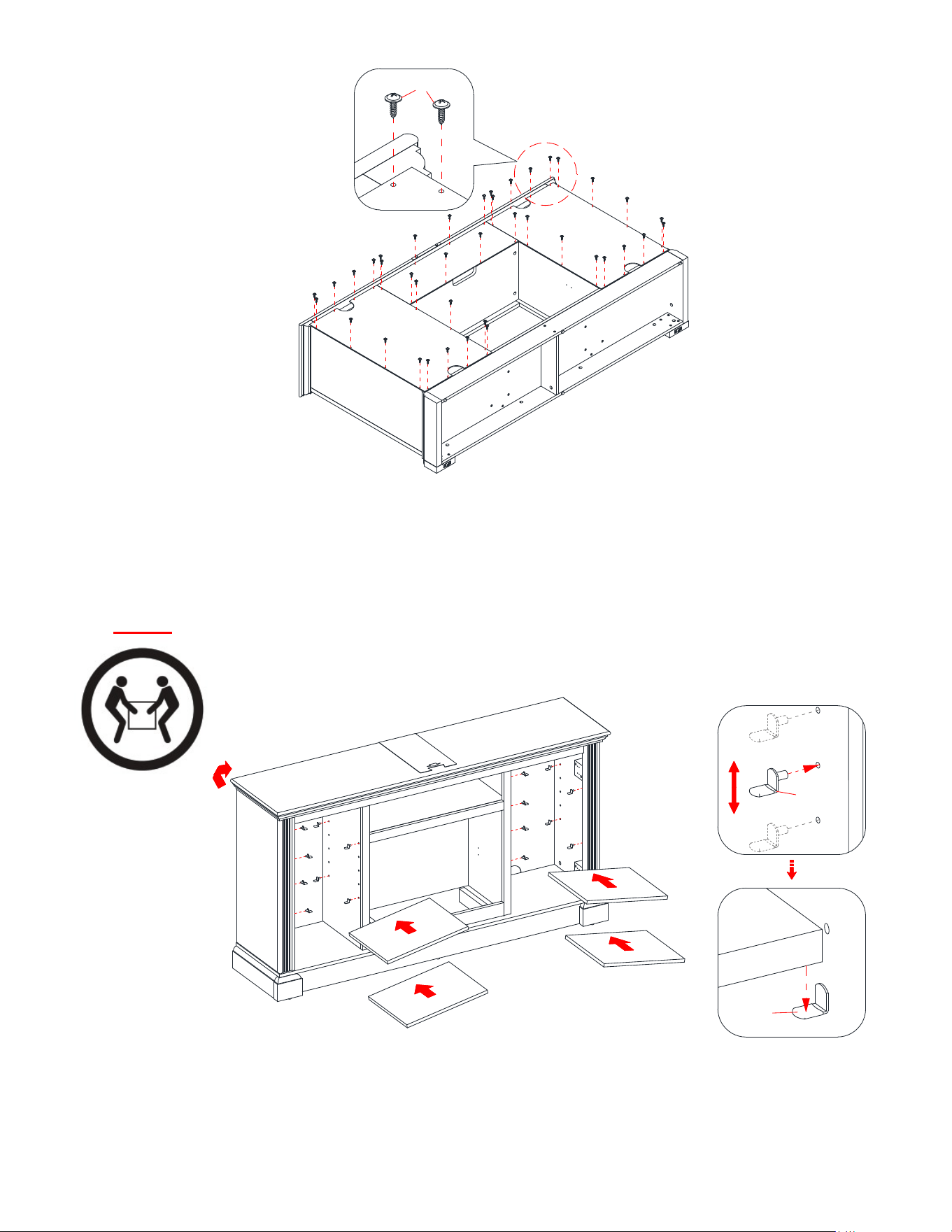
pilot holes on the back of Top Panel (K). Fasten it in place with the provided Washer Head Screws (5).
28. Using the pilot holes as a guide, align and attach the Side Back Panels (B1) to the mantel frame with
provided Washer Head Screws (5).
NOTE: We recommend attaching back panel with washer head screws at the corners first.
29. Ask for assistance to stand the assembled unit upright.
30. Completely tilt one Adjustable Shelf (Z) into one compartment as shown, then hold it horizontally to the
upper portion of the compartment.
31. Proceed to insert four Shelf Supports (13) into the holes at the desired height under the Adjustable Shelf
(Z). Then, rest the Adjustable Shelf (Z) onto the Shelf Supports (13).
32. Repeat the same process with the other Adjustable Shelves (Z).
T
V
B1
A1
B1
5
U
T
S
V
K
Z
Z
Z
Z
Z
13
13
90°
CAUTION: The unit is heavy so you may need assistance.
18
Assembly Instructions
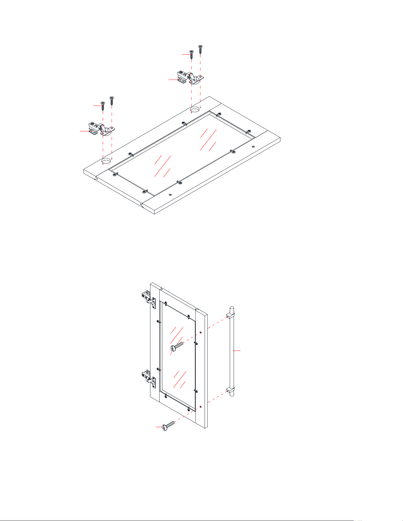
33. Extend two Door Hinges (E1) and rest the hinge cups onto the cutouts of each door (X). Secure the
Door Hinges (E1) in place by using two 15 mm Screws (9) in each hinge.
34. Using pilot holes as a guide, attach one Handle (F1) to the front of each Door (X) with two 22 mm Bolts
(10). Tighten with a Phillips screwdriver.
x 2
x 2
9
E1
9
E1
X
10
10
X
F1
19
Assembly Instructions
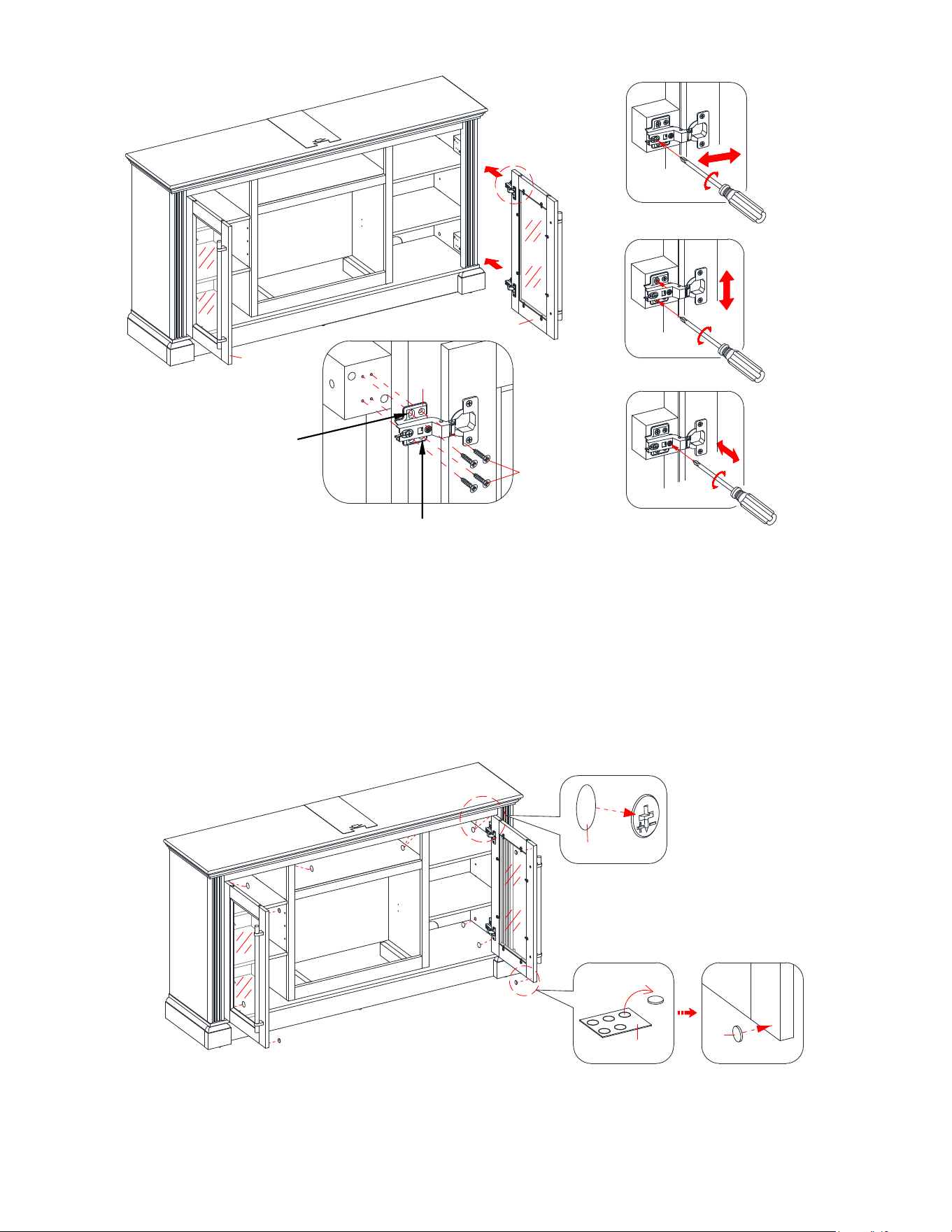
35. Pick up one Door (X) and attach the installed Door Hinges (E1) to the hinge supports pre-attached on the
Left Side Panel (S), using the pilot holes as a guide. Turn four 15 mm Screws (9) a few turns through the
CENTERS of the oval holes in the hinges. Move the door up or down to the desired position. Tighten the
screws with a Phillips screwdriver. Make sure that both door hinges engage and function properly.
36. Proceed to finish fastening the Door (X) to the Left Side Panel (S), using four 15 mm Screws (9) through
the round holes in the hinges.
37. Repeat the same process to attach the other Door (X) to the Right Side Panel (V).
38. Open and close the doors to make sure they are aligned and shut correctly. If necessary, adjust the screws
for a good fit. Fully tighten all 15 mm Nickel Screws (9) one final time when they are aligned properly.
39. Put the Paper Covers (15) onto the visible cam locks to conceal the cams.
40. Stick the Rubber Bumpers (16) on the outer corners of doors where the Partitions (T and U) are in
contact with.
Vertical
Adjustment
Horizontal
Adjustment
Depth
Adjustment
S
V
X
X
K
16
16
15
K
U
T
9
E1
Round hole
Oval hole
20
Assembly Instructions
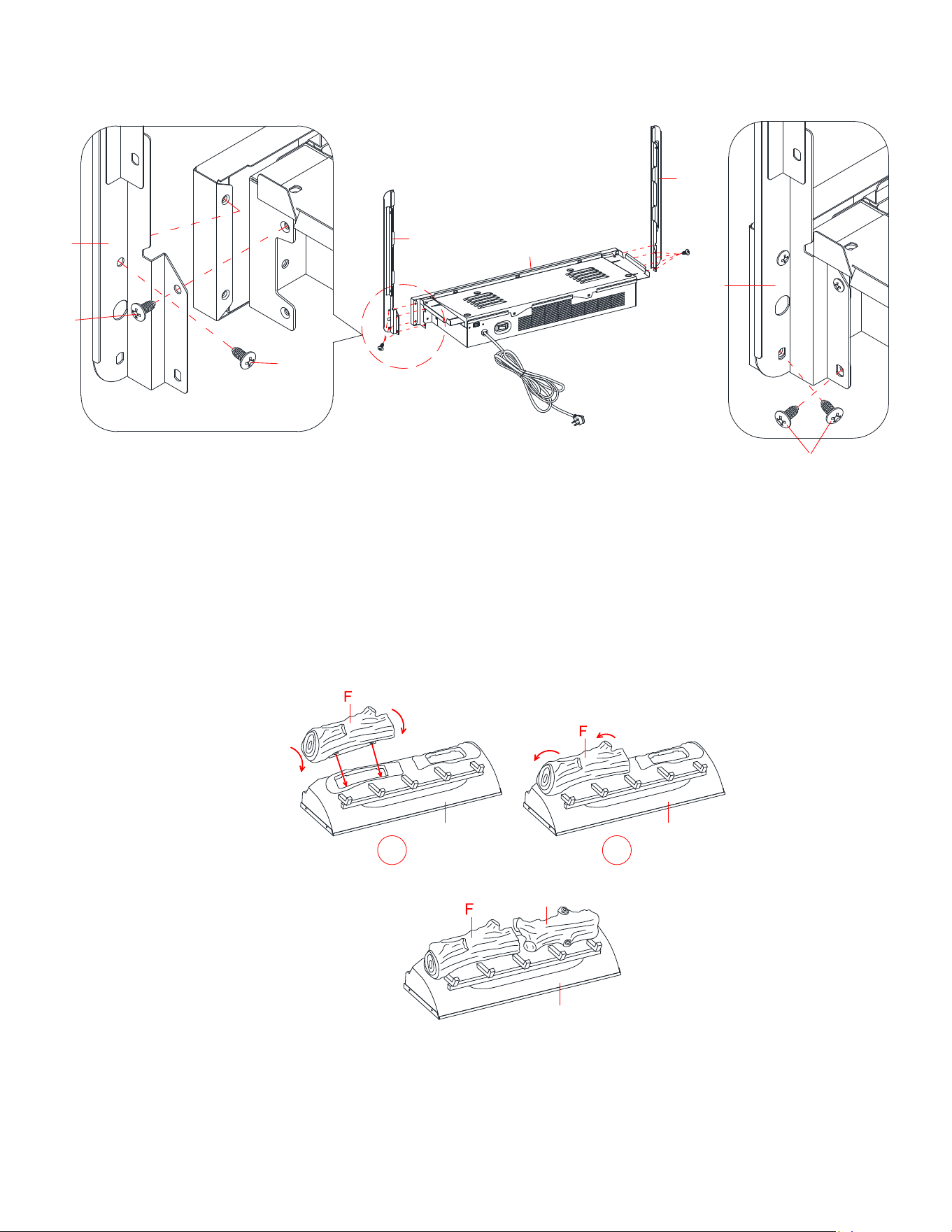
IMPORTANT NOTE: Use hand screwdriver, not power driver to assemble fireplace insert. See BILT
for video instructions.
41. See figure A: Fasten upper 2 Insert Screws (1) through the Upright Arm (C) into the Heater (A) until
tight.
42. See figure B: Fasten lower 2 Insert Screws (1) into the Upright Arm (C) until tight.
43. Fully tighten all 4 Insert Screws (1) one final time.
44. Repeat the same process with Upright Arm (B).
WARNING: Do not lift or transport the heater by using the upright arms.
IMPORTANT: Carefully follow the 2 steps below for inserting each log.
45. Install Left Log (F) into left hole of Ember Bed (E) by inserting front edge of base of the log into front
notches of ember bed hole.
46. Then tilt the log back to insert the rear edge of the log base into rear notches of ember bed hole (press
down log firmly to lock into position).
47. Repeat the above process for the Right Log (G).
Figure A Figure B
E E
1
2
G
E
1
A
C
B
C
1
1
A
A
C
21
A
E
E
A
Assembly Instructions
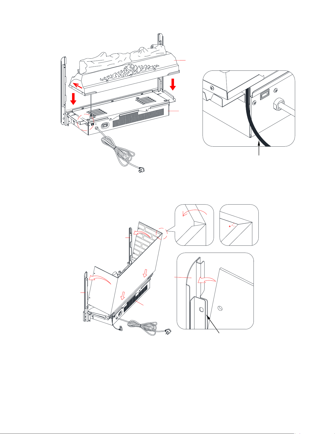
48. Set the Ember Bed (E) onto the Heater (A) as shown.
49. Push ember bed forward against the front flange of heater.
50. Position the USB cable as shown.
51. Fold the Wall Panel (H) as shown. Then position yourself at back side of Heater (A).
52. Hold Wall Panel (H) at the angle shown above and insert lower back edges into metal slots on back of
Heater (A).
53. Tilt Wall Panel (H) forward until bottom corners insert into lower U-channels on both Upright Arms (B
and C).
54. Continue to tilt Wall Panel (H) forward until the top corners insert into upper U-channels on both
Upright Arms (B and C).
USB cable
U-channels
H
A
C
B
H
90
H
H
B/C
22
Assembly Instructions
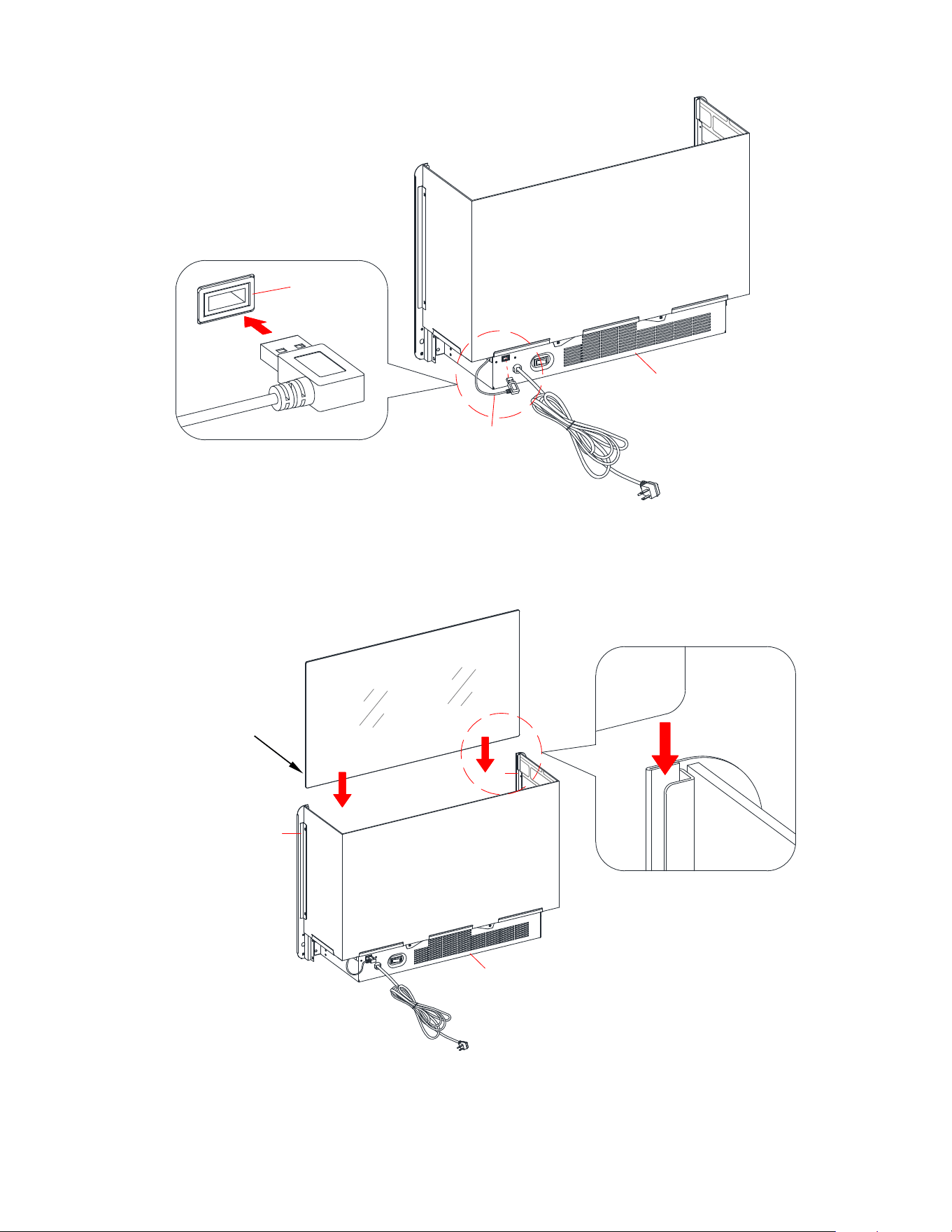
55. Fully plug the USB connector of the Ember Bed (E) into the back port of Heater (A).
56. Slide the Glass (I) into the inner U-channels on both Upright Arms (B and C) until the glass sits onto the
Heater (A). If needed, push top of upright arms in or out to accommodate glass. Make sure the top of the
Glass (I) is flush with the top of both Upright Arms (B and C).
The warning labels
on glass should face
outward
.
E
A
A
H
A
B
C
I
I
H
23
Assembly Instructions
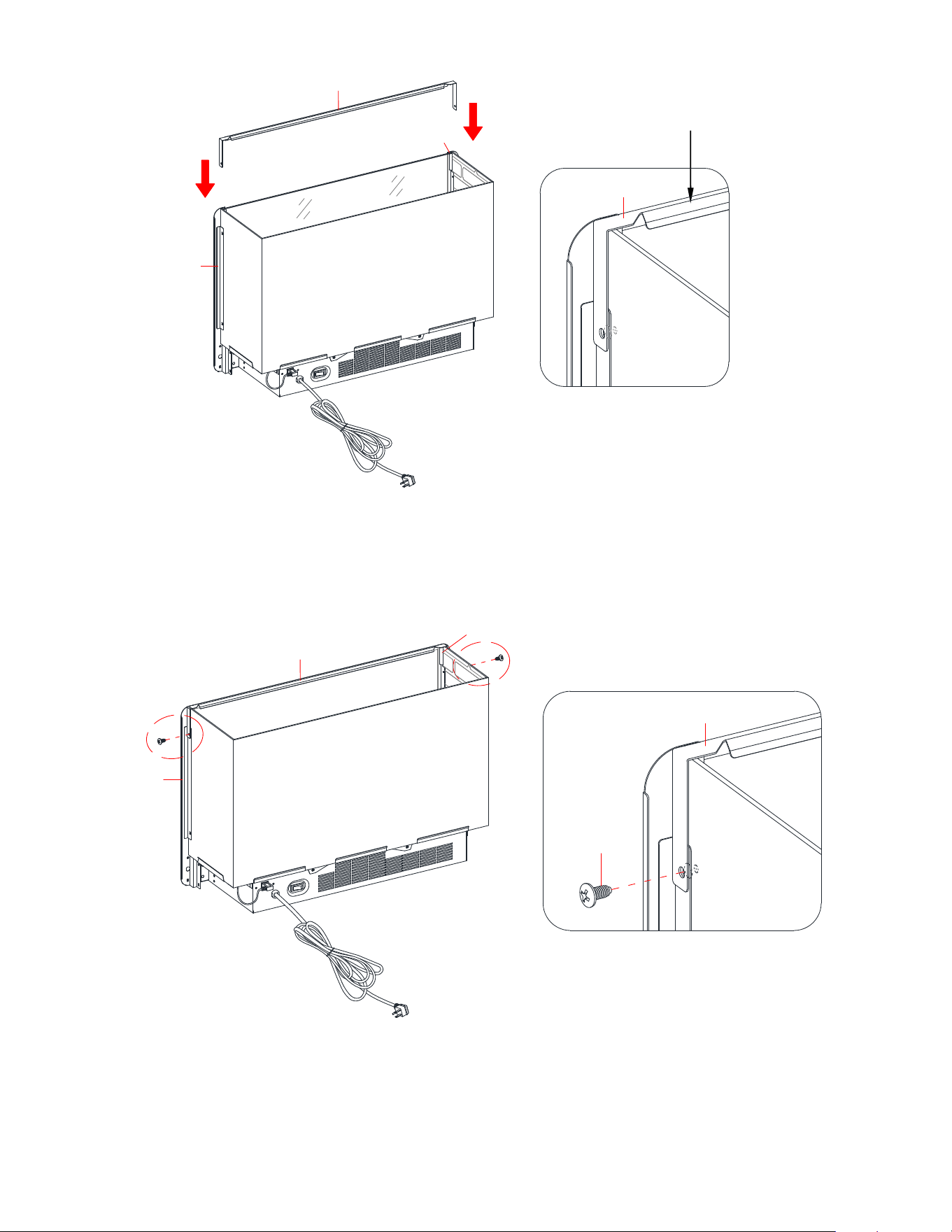
57. Position Top Connector Strap (D) over the Glass (I) and Upright Arms (B and C). Follow orientation
shown above.
58. Fasten Connector Strap (D) to both Upright Arms (B and C) using two Insert Screws (1) as shown
above. Holes must be in line for screw to pass through.
The bevel edge faces inside the unit.
D
I
H
C
B
D
H
D
H
C
B
D
1
H
24
Assembly Instructions
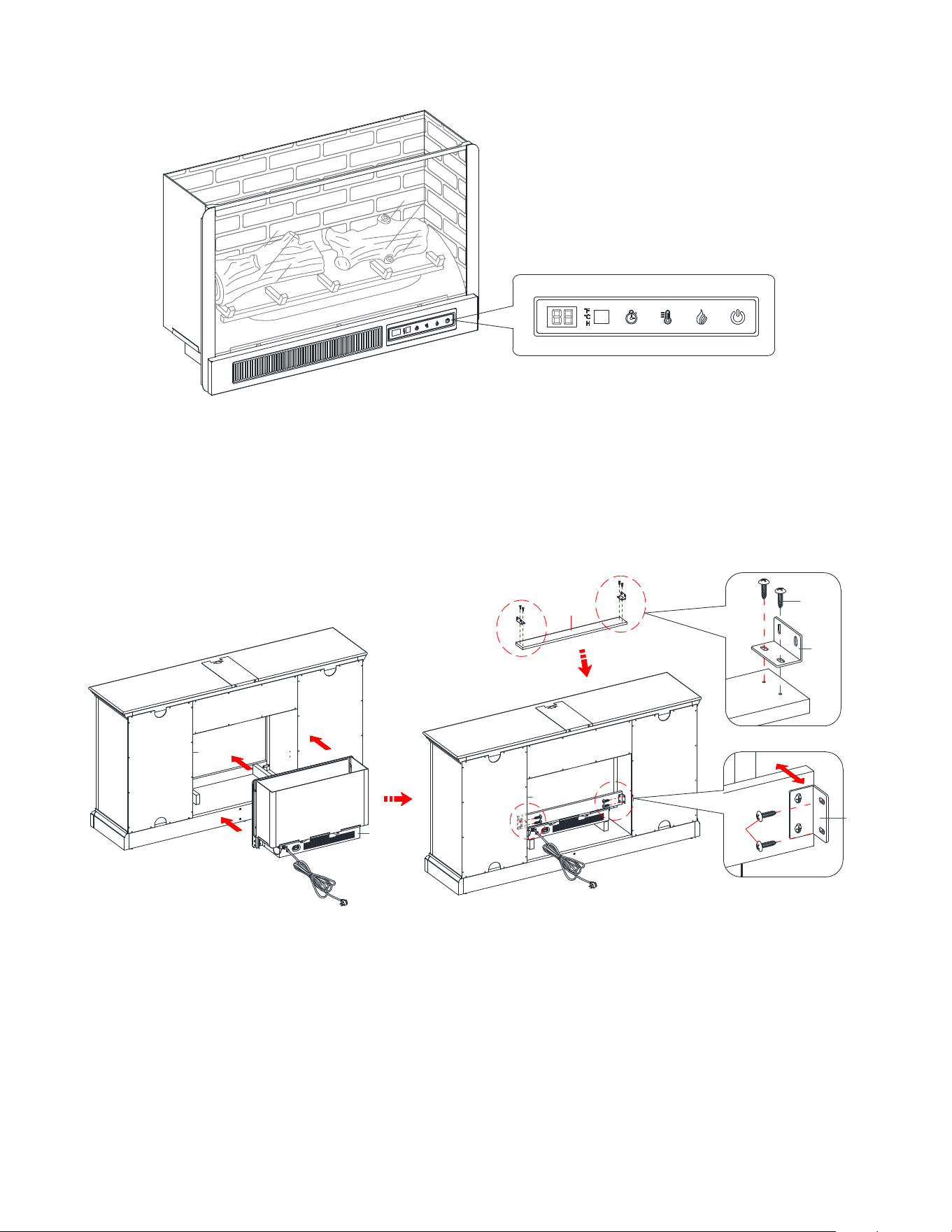
59. The firebox is now ready for the next assemble step.
60. Lift the fireplace insert carefully into the back of the assembled mantel and centre it on the bottom panel
in the opening.
61. Use the pilot holes as a guide, fasten two L-Shaped Metal Brackets (12) onto the Firebox Holder (Q)
with four 12 mm Pan Head Screws (11). Make sure that the right-angle side of metal brackets is flush
with the short edge of Firebox Holder (Q).
62. Use the pilot holes as a guide, fasten the Firebox Holder (Q) between the Partitions (T and U) with four
12 mm Pan Head Screws (11).
H
A
Q
11
Q
11
12
12
Q
K
K
Q
U
T
U
T
25
Assembly Instructions
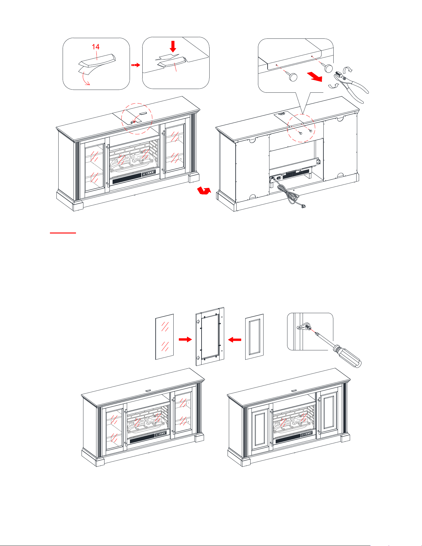
NOTE: To prevent your TV from tipping, you must install the acrylic TV stopper if you place a flat
panel television on the top panel. Otherwise, skip to next step.
63. Remove the paper backing of Acrylic Stopper (14), then properly align the acrylic stopper into the
cutout on the acrylic stopper template on the front of the Top Panel (K). Press down on the acrylic
stopper to adhere it to the Top Panel (K).
64. At the back of Top Panel (K), grip the heads of plastic tacks with pliers, with twisting motion pull tacks
loose to remove the acrylic stopper template.
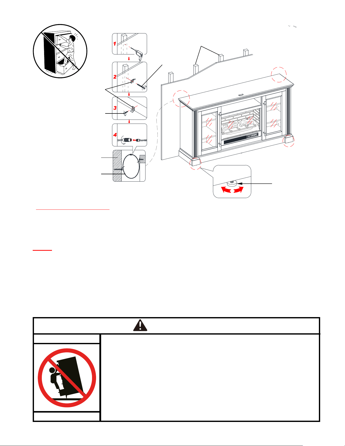
65. The doors of this unit are shipped with the glass insert panel. You can keep the doors as they are, or
interchange the insert panel with the Wood Door Panel (Y), depending on the desired configuration.
66. To change door panels, loosen the screws on the inside of the door and rotate the clips to remove the
panel. Replace with the desired panel, then rotate clips to secure the panel within the door frame and
tighten the screws.
K
K
14
K
Glass door panel
Wood door panel
Y
X
26
Assembly Instructions
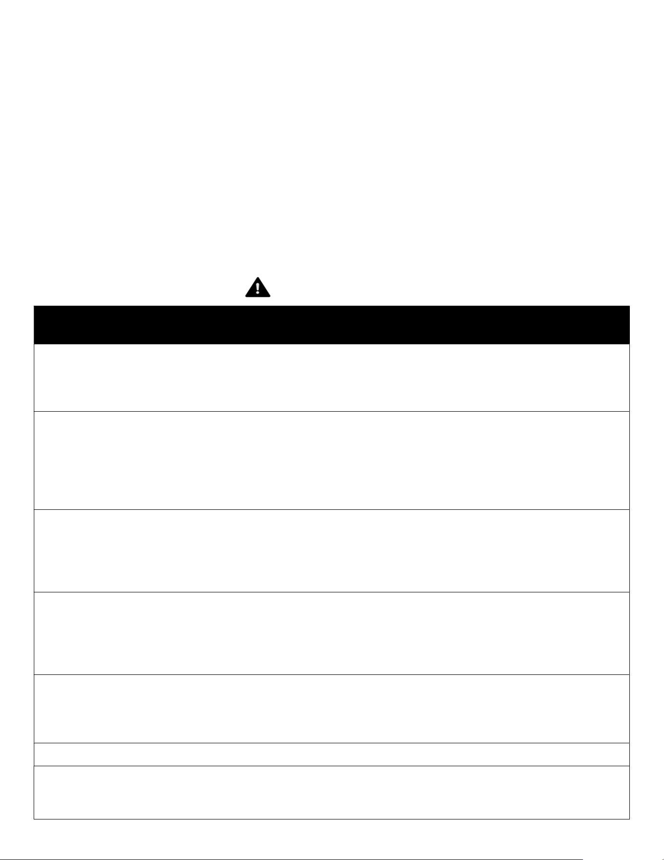
Tools required (not provided): Phillips screwdriver, stud finder, tape measure, pencil, power drill and 1/8” drill bit.
67. Ask for assistance to position the assembled fireplace at the desired location against a wall. If necessary,
adjust the floor levelers to correct the tilting and level the doors.
68. Now, follow the instructions printed on the plastic bag containing the Tipping Restraint Hardware to
attach the tip-over restraints to the unit and the wall.
NOTE: The tipping restraint hardware included is for wooden stud wall construction. It must be attached
to a wall stud. Depending upon your wall construction, different anchor hardware maybe required. Please
contact your local hardware store for assistance. Young children can be seriously injured by tipping
furniture. You must install the tipping restraint hardware with the unit to prevent the unit from tipping,
causing any accidents or damage. The tipping restraints are intended only as a deterrent, they are not a
substitute for proper adult supervision. The tipping restraints are not earthquake restraints. If you wish to
add the extra security of earthquake restraints, they must be purchased and installed separately.
69. Connect the fireplace to the power transformer. Follow the operating manual for the electric fireplace
insert to control your fireplace.
Children have died from furniture tip-over.
To reduce the risk of furniture tip-over:
ALWAYS install anti-tip device restraint provided.
FOR use with televisions weighing 100 lbs or less. Use with heavier televisions
may result in instability causing tip-over resulting in death or serious injury.
NEVER allow children to stand, climb or hang on any drawers, doors, or
shelves.
NEVER open more than one drawer at a time.
Place heaviest items in the lowest drawers.
Use of tip-over restraints may only reduce, but not eliminate, the risk of
tip-over.
WARNING
W
all
Wooden stud
Short screw
Long screw
Metal bracket
Floor leveler
Steel cable
Wall
Connector
Wall
W
all
27
Care and Maintenance
Use a soft, clean cloth that will not scratch the surface when dusting.
Use of furniture polishes is not necessary. Should you choose to use polishes, test first in an inconspicuous area.
Using solvents of any kind on your furniture may damage the finish.
Never use water to clean your furniture as it may cause damage to the finish.
Always use coasters under beverage glasses and flowerpots.
Liquid spills should be removed immediately. Using a soft, clean cloth, blot the spill gently. Avoid rubbing.
Always use protective pads under hot dishes and plates. Heat can cause chemical changes that may create
spotting within the furniture finish.
Stains or marks from crayons or ink markers will be difficult to remove.
In the event that your furniture is stained or otherwise damaged during use, we recommend that you call a
professional to repair your furniture.
Check bolts/screws periodically and tighten them if necessary.
A touch-up pen has been provided to minimize the small nicks or scratches that may occur during
assembly or shipping.
WARNING
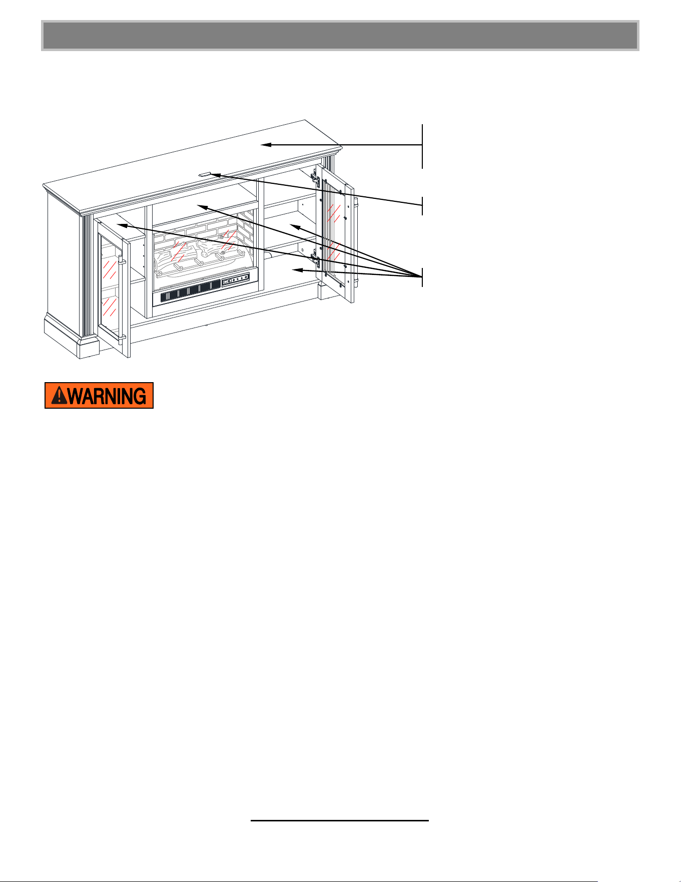
Please use your furniture correctly and safely. Improper use can cause safety hazards, or damage to
your furniture or household items. Carefully read the following safety information.
This unit is not intended for use with CRT TVs. The top surface maximum weight capacity is 100 lb (45.4 kg) and
maximum load 75 in. (190.5 cm) diagonal flat-panel TV. The shelf maximum recommended weight
allowance is 50 lb (22.7 kg). Use with heavier televisions may result in instability causing tip over resulting
in death or serious injury.
Death or serious injury may occur when children climb on audio and/or video equipment furniture. A remote
control or toys placed on the furnishing may encourage a child to climb on the furnishing and as a result may
tip over onto the child.
NEVER allow children to climb or play with the TV or furnishing supporting the TV.
NEVER place toys, food, remote, etc. on top of the TV or TV furnishing.
ALWAYS use either the safety hardware as instructed or other wall anchoring device.
Relocating audio and/or video equipment to furniture not specifically designed to support audio and/or video
equipment may result in death or serious injury due to furniture collapse or overturning onto a child.
NEVER place a TV on furniture that is not intended to support a TV.
NEVER exceed the maximum size and weight of the TV shown in the instructions.
Be sure to refer to the TV warning label as shown in the instructions.
Overloading drawers and shelves may result in furniture that can break or sag, or tip-over which may result in
injury.
NEVER exceed the weight limits shown in the instructions.
Place the heavier items on lower shelves as far back from the front as possible.
Load the bottom surfaces first to avoid top-heavy furniture.
Moving furniture that is not designed to be moved or equipped with casters may result in injury or damage to
furnishings or personal property.
ALWAYS unload shelves and drawers, starting with the top surfaces, before moving.
NEVER push or pull furniture on carpet. Have a friend help lift properly to move and/or reposition it.
The unit is not meant as a seat and no one should be sitting or standing on the unit.
Clean the metal trim using a soft cloth, slightly dampened with citrus oil-based product and buff with a clean
soft cloth. DO NOT use brass polish or household cleaners as these products will damage the metal trim. Citrus
oil-based products can be obtained at supermarkets or hardware stores.
28
MANUFACTURER: Whalen Furniture Manufacturing
CATALOG : Hutchinson 65” Fireplace Console
MODEL #: MNFP65MR26HLAWT / MNFP65MR26HLADK
QUALITY GUARANTEE
We are confident that you will be delighted with your Whalen Furniture purchase.
Should this product be defective in workmanship or materials or fail under normal use, we will repair or
replace it for up to one (1) year from date of purchase. Every Whalen Furniture product is designed to meet
your highest expectations. We guarantee that you will immediately see the value of our fine furniture.
This warranty gives you specific legal rights and you may also have other rights which vary from state to state
or province to province.
Whalen Furniture Manufacturing
1578 Air Wing Road, San Diego, CA 92154, USA
Customer Service: 1-866-942-5362
8:30 a.m. - 4:30 p.m., PST, Monday to Friday
www.whalenfurniture.com
M A X I M U M R E C O M M E N D E D W E I G H T L O A D S
MAXIMUM LOAD 22.7 kg / 50 lb
THIS UNIT IS NOT INTENDED FOR USE WITH CRT TVS. USE ONLY WITH FLAT
PANEL TVS AND AUDIO/VIDEO EQUIPMENT MEETING RECOMMENDED SIZE AND WEIGHT LIMITS.
NEVER USE WITH LARGER/HEAVIER THAN RECOMMENDED FLAT PANEL TVS OR EQUIPMENT. TO
AVOID INSTABILITY, PLACE FLAT PANEL TV IN THE CENTER OF THE UNIT; THE BASE OF THE
TELEVISION MUST BE ABLE TO REST ON THE SUPPORTING SURFACE OF THE UNIT WITHOUT
OVER-HANGING THE EDGES. IMPROPERLY POSITIONED FLAT PANEL TVS, OR FLAT PANEL TVS
INCLUDING OTHER EQUIPMENT THAT EXCEED RECOMMENDED SIZE AND WEIGHT LIMITS
COULD FALL OFF OR BREAK THE UNIT, CAUSING POSSIBLE SERIOUS INJURY. FOR USE WITH
TELEVISIONS WEIGHING 100 LB (45.4 KG) OR LESS. USE WITH HEAVIER TELEVISIONS MAY RESULT IN
INSTABILITY CAUSING TIP OVER RESULTING IN DEATH OR SERIOUS INJURY.
FITS MOST FLAT PANEL TVS UP
TO 190.5 cm / 75 in. DIAGONAL
AND 45.4 kg / 100 lb
PLACE TV BEHIND THE STOPPER