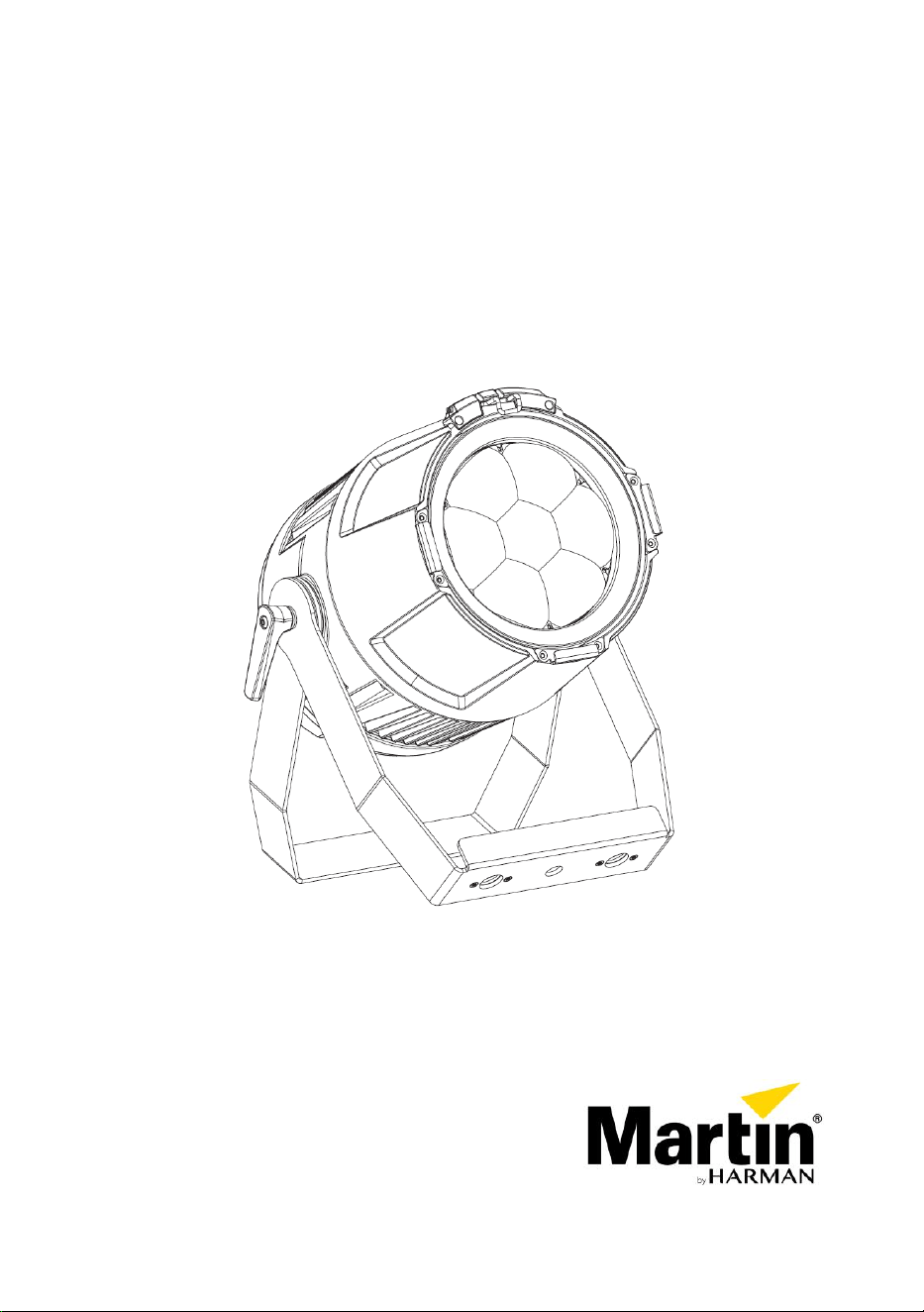
ELP PAR
User Guide

©2021-2023 HARMAN PROFESSIONAL DENMARK ApS. All rights reserved.
Features, specifications and appearance are subject to change without notice.
HARMAN PROFESSIONAL DENMARK ApS and all affiliated companies
disclaim liability for any injury, damage, direct or indirect loss, consequential or
economic loss or any other loss occasioned by the use of, inability to use or
reliance on the information contained in this document. Martin is a registered
trademark of HARMAN PROFESSIONAL DENMARK ApS registered in the
United States and/or other countries.
HARMAN PROFESSIONAL DENMARK ApS, Olof Palmes Allé 44, 8200
Aarhus N, Denmark
HARMAN PROFESSIONAL SOLUTIONS U.S., 8500 Balboa Blvd., Northridge
CA 91329, USA
www.martin.com
ELP PAR User Guide Revision C

Table of contents
Safety information ................................................................................. 4
Introduction ........................................................................................... 9
Before using the product for the first time ....................................... 9
Fixture overview ................................................................................. 10
Physical installation ............................................................................ 11
Standing the fixture on a flat, horizontal surface ........................... 12
Fastening the fixture to a flat surface ............................................ 13
Mounting the fixture on a truss ...................................................... 13
Securing with a safety cable ......................................................... 14
Connecting to AC power ..................................................................... 15
Linking fixtures to power in a chain ............................................... 16
Connecting to data ............................................................................. 17
Tips for reliable data transmission ................................................ 17
Connecting the DMX data link....................................................... 17
Fixture setup ....................................................................................... 18
DMX address setting ..................................................................... 19
DMX mode .................................................................................... 19
Raw, extended and calibrated modes ........................................... 20
Tungsten emulation mode ............................................................ 20
Dimming curves ............................................................................ 20
Dimming speed and smoothness .................................................. 21
Blackout or Hold if DMX signal stops ............................................ 21
Scene capture ............................................................................... 21
Cooling mode ................................................................................ 22
Display rotation ............................................................................. 23
Display intensity ............................................................................ 23
Temperature units ......................................................................... 23
Resetting to factory defaults ......................................................... 23
Fixture test .................................................................................... 24
Fixture information ........................................................................ 24
DMX Live ...................................................................................... 26
Resetting the fixture ...................................................................... 26
Manual control .............................................................................. 26
Focus shortcut .............................................................................. 27
Control / Settings DMX channel .................................................... 27
Effects ................................................................................................ 28
RDM ................................................................................................... 30
Maintenance ....................................................................................... 32
Cleaning ........................................................................................ 32
Uploading new firmware ............................................................... 33
Service and repairs ....................................................................... 34
DMX protocol – Basic Mode (default) ................................................. 35
DMX protocol – Compact Mode .......................................................... 39
Control menus .................................................................................... 40
Troubleshooting .................................................................................. 45
Dimensions ......................................................................................... 46
Specifications ..................................................................................... 47
4 Martin
®
ELP PAR User Guide
Safety information
WARNING!
Read the safety precautions in this manual before
installing, operating or servicing this product.
The following symbols are used to identify important safety information on
the product and in this manual:
Warning!
Safety hazard.
Risk of severe
injury or death.
Warning!
Powerful light
emission. Risk
of eye injury.
Warning!
See user
manual for
important
safety
information.
Warning!
Hazardous
voltage. Risk
of lethal or
severe electric
shock.
Warning!
Hot surfaces
and fire
hazard.
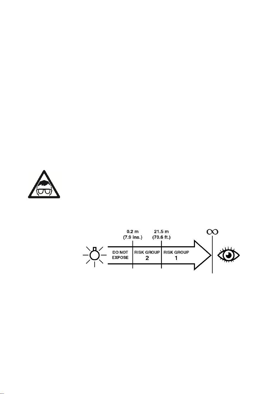
Warning! Risk Group 2 product according to EN 62471 and
IEC/TR 62778. Possibly hazardous radiation emitted from this
product. May be harmful to the eyes. Do not stare at operating
lamp and do not view the light output with optical instruments
or any device that may concentrate the beam.
This lighting fixture is for professional use only and must be
installed by a qualified technician. It is not for household use. It
presents risks of severe injury or death due to fire hazards,
electric shock and falls. It produces a powerful, concentrated
beam of light that can create a fire hazard or a risk of eye
injury if the safety precautions below are not followed. Respect
all locally applicable laws, codes and regulations when
installing, operating or servicing the fixture.
The light source contained in this fixture must be replaced by
Martin Service or an authorized Martin Service partner only.
Martin
®
ELP PAR User Guide 5
Install, operate and service Martin products only as directed in
their user manuals, or you may create a safety hazard or
cause damage that is not covered by product warranties.
Follow the safety precautions listed below and observe all
warnings in this manual and printed on the product. Before
you install, operate or service the fixture, check the Martin
website at www.martin.com and make sure that you have the
latest user documentation for the fixture. Document revisions
are indicated at the bottom of page 2.
Technical Support
If you have questions about how to install or operate the
fixture safely, please contact Harman Professional Technical
support:
• For technical support in North America, please contact:
HProT[email protected]
Phone: (844) 776-4899
• For technical support outside North America, please
contact your national distributor.
Protection from electric shock
Do not expose the fixture to rain or moisture.
Disconnect the fixture from AC power before carrying out any
installation or maintenance work and when the fixture is not in
use.
Ensure that the fixture is electrically connected to ground
(earth).
Use only a source of AC power that complies with local
building and electrical codes and has both overload and
ground-fault (earth-fault) protection.
Socket outlets or external power switches used to supply the
fixture with power must be located near the fixture and easily
accessible so that the fixture can easily be disconnected from
power.
Isolate the fixture from power immediately if the power plug or
any seal, cover, cable, or other component is damaged,
defective, deformed, wet or showing signs of overheating. Do
not reapply power until repairs have been completed.

6 Martin
®
ELP PAR User Guide
Before using the fixture, check that all power distribution
equipment and cables are in perfect condition and rated for
the current requirements of all connected devices.
Use only Neutrik powerCON TRUE1 TOP cable connectors to
connect to the fixture’s power sockets.
Do not connect devices to power in a chain that will exceed
the electrical ratings of any cable or connector used in the
chain.
To connect fixtures to mains power in a chain, you must first
obtain 12 AWG or 2.5 mm
2
power input and throughput cables
that are 16 A rated and temperature-rated to suit the
application. In the USA and Canada the cables must be UL-
listed, type SJT or equivalent. In the EU the cables must be
type H05VV-F or equivalent. Suitable cables with Neutrik
powerCON TRUE1 TOP connectors are available from Martin
(see ‘Accessories’ on page 49). If you use these cables, you
can connect fixtures to power in a linked chain, POWER OUT
throughput socket to POWER IN input socket, but do not link
more than:
• four (4) ELP PAR fixtures in total at 100-120 V, or
• seven (7) ELP PAR fixtures in total at 200-240 V.
If you intend to connect other devices to the POWER OUT
socket in a daisy chain, add together the maximum current
draw of all the devices in the chain. Do not create a chain of
devices whose total maximum current draw will exceed the
maximum current rating of any connector in the chain. The
maximum permitted current at the POWER IN connector is
16 A. The maximum permitted current at the POWER OUT
connector is 12 A.
The voltage and frequency at the POWER OUT socket are the
same as the voltage and frequency applied to the POWER IN
socket. Only connect devices to the POWER OUT socket that
accept this voltage and frequency.
Protection from burns and fire
Do not operate the fixture if the ambient temperature (T
a
)
exceeds 40° C (104° F).
The surface of the product casing can reach up to 71° C
(160° F) during operation. Avoid contact by persons
Martin
®
ELP PAR User Guide 7
and materials. Allow the fixture to cool for at least 15 minutes
before handling.
Keep flammable materials well away from the fixture. Keep all
combustible materials (e.g. fabric, wood, paper) at least 0.5 m
(1.7 ft.) away from the fixture housing.
Ensure that there is free and unobstructed airflow around the
fixture. Provide a minimum clearance of 0.5 m (1.7 ft.) around
fans and air vents.
Do not use the fixture to illuminate surfaces within 1 m (3.3 ft.)
of the fixture.
Do not stick filters, masks or other materials onto any optical
component.
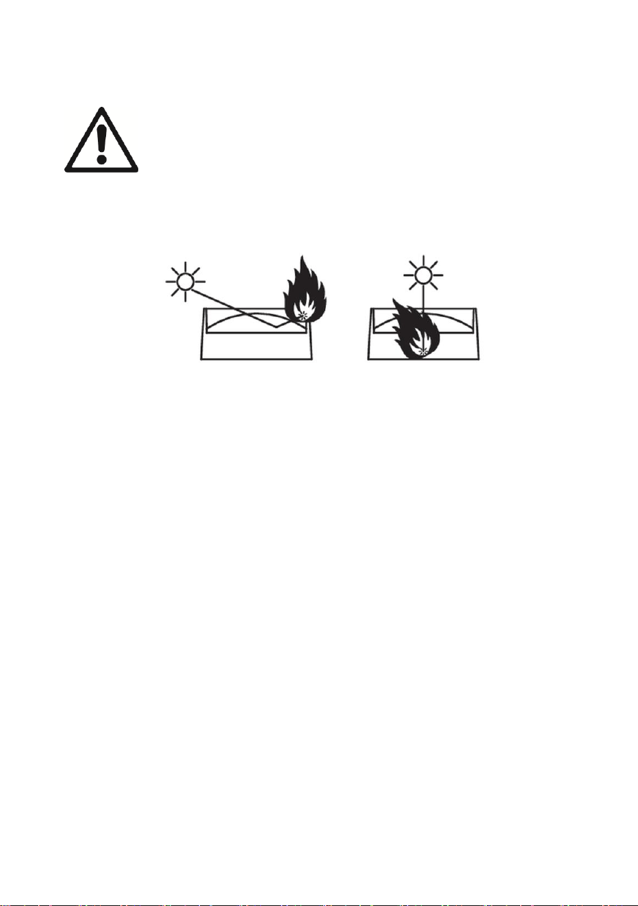
The fixture’s lenses can focus the sun’s rays, creating a risk of
fire and damage. Do not expose the front of the fixture to
sunlight or any other bright light source.
Protection from eye injury
Warning! Risk Group 2 product according to EN 62471 and
IEC/TR 62778.
The ELP PAR fixture falls into the following risk groups
according to EN 62471 and IEC/TR 62778 at the distances
indicated below.
The luminaire should be positioned so that prolonged staring
into the luminaire at a distance closer than 21.5 m is not
expected.
Do not look directly into the product’s light output.
Do not look at operating lamp. Eye injury may result.
Do not look at the light output with magnifiers, telescopes,
binoculars or similar optical instruments that may concentrate
the light output.
Ensure that persons are not looking directly into the front of

8 Martin
®
ELP PAR User Guide
the fixture when the product lights up suddenly. This can
happen when power is applied, when the product receives a
DMX signal, or when certain control menu items are selected.
To minimize the risk of eye irritation or injury, disconnect the
fixture from power at all times when the fixture is not in use
and provide well-lit conditions to reduce the pupil diameter of
anyone working on or near the fixture.
Protection from injury
The fixture is not portable when installed.
Ensure that any supporting structure and/or hardware used
can hold at least 10 times the weight of all the devices they
support.
If suspending from a rigging structure, fasten the fixture to a
rigging clamp. Do not use safety cables as the primary means
of support.
If the fixture is installed in a location where it may cause injury
or damage if it falls, install as directed in this manual a
secondary attachment such as a safety cable that will hold the
fixture if a primary attachment fails. The secondary attachment
must be approved by an official body such as TÜV as a safety
attachment for the weight that it secures, must comply with EN
60598-2-17 Section 17.6.6 and must be capable of bearing a
static suspended load that is ten times the weight of the fixture
and all installed accessories.
Check that all external covers and rigging hardware are
securely fastened.
Block access below the work area and work from a stable
platform whenever installing, servicing or moving the fixture.
Do not operate the fixture with missing or damaged covers,
shields or any optical component.
In the event of an operating problem, stop using the fixture
immediately and disconnect it from power. Do not attempt to
use a fixture that is obviously damaged.
Do not modify the fixture in any way not described in this
manual or install other than genuine Martin parts.
Refer any service operation not described in this manual to a
qualified technician.

Martin
®
ELP PAR User Guide 9
Introduction
The ELP PAR is a bright LED PAR Can with calibrated color output from
seven RGBW LEDs and a motorized zoom with an angle that varies from
5.6° to 57.6° (field angle, one-tenth peak) or 4.2° to 35.4° (beam angle, half-
peak). It offers electronic dimming and strobe and features a bracket for floor
or truss mounting.
The ELP PAR can be controlled using any DMX-compliant controller and is
RDM-compatible.
The fixture is supplied with a folding mounting bracket.
Before using the product for the first time
1. Read ‘Safety information’ on page 4 before installing, operating or
servicing the fixture.
2. Unpack and ensure that there is no transportation damage before using
the fixture. Never attempt to operate a damaged fixture.
3. Check that the voltage and frequency of the local power source match
the mains power requirements of the fixture.
4. Either hard-wire the fixture to an AC mains power source or provide a
power input cable and local power plug as described in this manual and
connect to an AC mains power outlet.
5. Check the support pages on the Martin Professional website at
www.martin.com for the most recent user documentation and technical
information about the fixture. Martin user manual revisions are identified
by the revision letter at the bottom of the inside cover.
Be prepared for the fixture to suddenly emit bright light when power is
applied.
10 Martin
®
ELP PAR User Guide
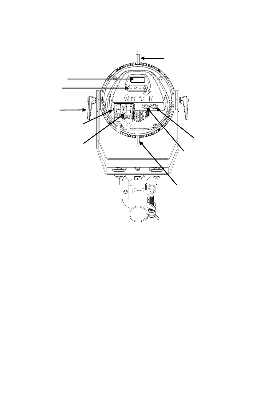
Fixture overview
1 – Display
2 – Control buttons
3 – Tilt adjustment handle
4 – Mains power IN (Neutrik powerCON TRUE1 TOP)
5 – Mains power OUT / THRU (Neutrik powerCON TRUE1 TOP)
6 – DMX IN (Neutrik 5-pin XLR)
7 – DMX OUT / THRU (Neutrik 5-pin XLR)
8 – Carabiner clips (not supplied) for safety cable
2
1
3
4
5
7
6
8
8
Martin
®
ELP PAR User Guide 11
Physical installation
Read ‘Safety information’ on page 4 before installing the
fixture.
Warning! See illustration below. Position or shade the
head so that the front of the head will not be exposed to
sunlight or any other strong light source from any angle –
even for a few seconds. The fixture can focus the sun’s
rays internally, creating a risk of fire and damage.
The fixture is designed for indoor use only and must be used in a dry
location with adequate ventilation. Ensure that none of the fixture’s
ventilation slots are blocked.
You can either fasten the fixture to a secure structure (such as a rigging
truss) or surface. You can also stand it on a secure surface. Do not place
the fixture in a location where it can be moved, fall over, or present a danger
of tripping or injury.
If you install the fixture in a location where it may cause injury or damage if it
falls, secure it as directed in this user manual using a securely anchored
safety cable that will hold the fixture if the primary fastening method fails.
Martin can supply safety cables and rigging clamps that are suitable for use
with the fixture (see ‘Accessories’ on page 49).
Avoiding damage from other light sources
Important! Do not point the light output from other lighting fixtures at the ELP
PAR, as powerful light can damage the display.
12 Martin
®
ELP PAR User Guide
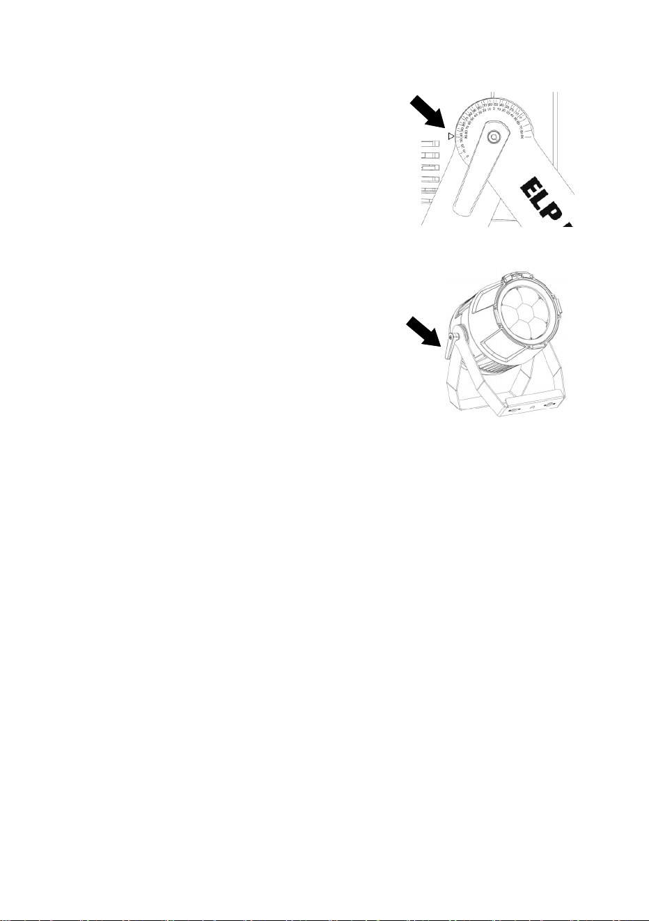
Mounting bracket angle scales
See illustration on right. The fixture’s mounting
bracket has angle scales printed on both sides
next to the adjustment handles. The scales show
the precise angle at which the head is tilted. There
are two scales. The inner scale is for use when
standing the fixture on the floor. The outer scale is
for use when flying the fixture overhead.
Standing the fixture on a flat, horizontal surface
Use a stable horizontal surface that can support at
least 10 times the weight of all the fixtures and
equipment that it will support.
See illustration on right. The fixture can be
placed on the surface by releasing the adjustment
handles (arrowed) on both sides of the fixture, fully
opening the legs of the mounting bracket, and then
re-tightening the adjustment handles.
Martin
®
ELP PAR User Guide 13
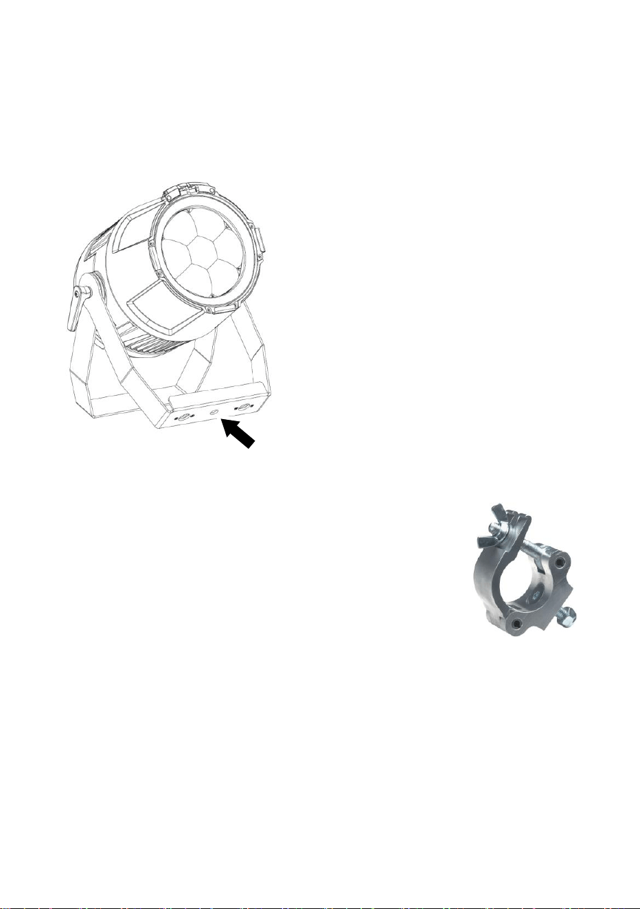
Fastening the fixture to a flat surface
Use a stable horizontal surface that can support at least 10 times the weight
of all the fixtures and equipment that it will support. Ensure that all fasteners
used can support at least ten times the weight of all the fixtures and
equipment that they will support.
To fasten the fixture to a surface:
1. See illustration on left. Pass an M12,
grade 8.8 steel minimum, bolt or
screwbolt through the hole (arrowed) in
the center of the main mounting
bracket leg and into the surface.
2. If using a bolt, secure with a washer
and self-locking nut.
3. Check that the fixture is held securely.
4. If you install the fixture in a location
where it may cause injury or damage if
it falls, secure it as directed below with
a securely anchored safety cable that
will hold the fixture if the primary
fastening method fails.
Mounting the fixture on a truss
The fixture can be clamped to a truss or similar rigging
structure in any orientation. When installing the fixture
hanging vertically down, you can use an open-type clamp
such as a G-clamp. When installing in any other
orientation, you must use a half-coupler clamp (see
illustration on right) that completely encircles the truss
chord.
To clamp the fixture to a truss:
1. Check that the rigging structure can support at least ten times the weight
of all fixtures and equipment to be installed on it.
2. Block access under the work area.
3. Either:
- Bolt a rigging clamp directly to the fixture’s mounting bracket using
an M12 grade 8.8 steel bolt and self-locking washer, or
14 Martin
®
ELP PAR User Guide
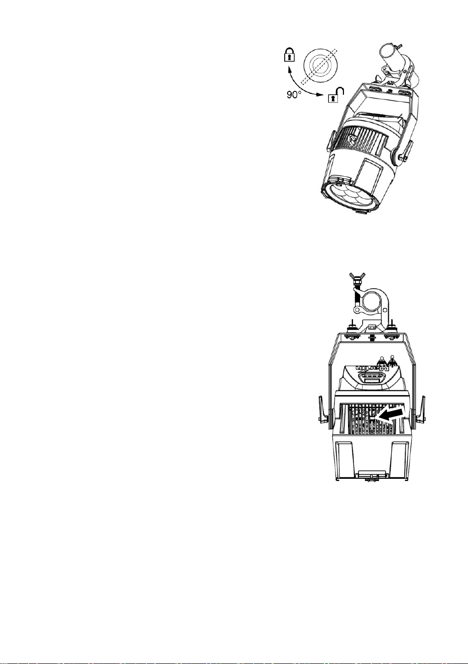
- Bolt a rigging clamp to a Martin omega
bracket (available as an accessory by
ordering P/N 91602001 from your
Martin supplier) using a grade 8.8 steel
bolt. See illustration on right. Fold the
legs of the fixture’s mounting bracket
together and fasten the omega bracket
securely to the mounting bracket. Turn the
quarter-turn fasteners on the omega
bracket a full 90° to lock.
4. Working from a stable platform, hang the fixture
with its clamp on the truss and fasten the clamp
securely.
5. Loosen the adjustment handles on both sides of the fixture, adjust the
fixture’s tilt angle, and re-tighten the handles.
6. Secure the fixture with a safety cable as directed below.
Securing with a safety cable
1. Obtain a safety cable (or other secondary
attachment) that is approved for the weight of the
fixture.
2. See illustration on right. There is one attachment
point (arrowed) in the cooling vent on the top of
the fixture and a second, identical attachment
point on the bottom of the fixture. Fasten the
cable to one of the safety cable attachment
points (arrowed) on the fixture by either looping it
around the attachment point or using a carabiner
clip.
Do not simply loop the safety cable around the
legs of the mounting bracket, as this will leave
the fixture unsecured if the fixture separates from
the mounting bracket.
3. Remove as much slack as possible from the safety cable and fasten it to
a secure anchoring point.
4. Make sure that the safety cable will hold the fixture if a primary
attachment fails.
Your Martin dealer can supply suitable safety cables and rigging clamps
(see ‘Accessories’ on page 49).

Martin
®
ELP PAR User Guide 15
Connecting to AC power
Read ‘Safety information’ on page 4 before connecting the
fixture to AC mains power.
Before you connect other fixtures to the POWER OUT socket,
see ‘Linking fixtures to power in a chain’ on page 16.
For protection from electric shock, the fixture must be
grounded (earthed). The power distribution circuit must be
equipped with a fuse or circuit breaker and ground-fault (earth-
fault) protection.
Socket outlets or external power switches used to supply the
fixture with power must be located near the fixture and easily
accessible so that the fixture can easily be disconnected from
power.
Do not use an external dimming system to supply power to the fixture, as
this may cause damage to the fixture that is not covered by the product
warranty.
The fixture requires a power input cable with a Neutrik powerCON TRUE1
NAC3FX-W (TOP) female cable connector for AC mains power input. The
cable must meet the requirements listed under “Protection from electric
shock” on page 5. Martin can supply suitable cables with female TRUE1
TOP input connectors 1.5 m (4.9 ft.) or 5 m (16.4 ft.) long, as well as loose
female TRUE1 TOP input connectors (see “Accessories” on page 49).
The fixture can be hard-wired to a building electrical installation if you want
to install it permanently, or a power plug that is suitable for the local power
outlets can be installed on the power cable. If you install a power plug on the
power cable, follow the plug manufacturer’s instructions and connect the
wires in the power cable as shown in this table:
Earth, Ground or
Neutral or N
Live or L
US system
Green
White
Black
EU system
Yellow/green
Blue
Brown
The fixture has an auto-ranging power supply that accepts AC mains power
at 100-120/200-240 V at 50/60 Hz. Do not apply AC mains power at any
other voltage or frequency to the fixture.

16 Martin
®
ELP PAR User Guide
Linking fixtures to power in a chain
If you obtain a 12 AWG / 2.5 mm
2
power input cable and 12 AWG / 2.5 mm
2
throughput cables from Martin (see “Accessories” on page 49), you can
relay mains power from one fixture to another by connecting fixtures to
power in a linked daisy-chain, POWER OUT throughput socket to POWER
IN input socket.
Using 12 AWG / 2.5 mm
2
cables from Martin, you can create a daisy chain
of linked fixtures that contains:
• maximum four (4) ELP PAR fixtures in total at 100-120 V, or
• maximum seven (7) ELP PAR fixtures in total at 200-240 V.
Martin
®
ELP PAR User Guide 17
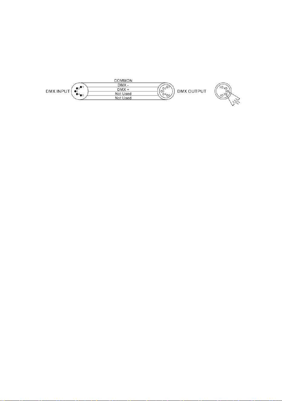
Connecting to data
A DMX 512 data link is required in order to control the fixture via DMX. The
fixture has 5-pin XLR connectors for DMX data input and output.
The number of daisy-chained fixtures is limited by the number of DMX
channels required by the fixtures in relation to the maximum 512 channels
available in one DMX universe. Note that if independent control of a fixture is
required, it must have its own DMX channels. Fixtures that are required to
behave identically can share the same DMX address and channels. To add
more fixtures or groups of fixtures when the above limit is reached, add a
DMX universe and another daisy-chained link.
Tips for reliable data transmission
Use shielded twisted-pair cable designed for RS-485 devices: standard
microphone cable cannot transmit control data reliably over long runs. 24
AWG cable is suitable for runs up to 300 meters (1000 ft.). Heavier gauge
cable and/or an amplifier is recommended for longer runs. The pinout on all
connectors is pin 1 = shield, pin 2 = cold (-), and pin 3 = hot (+). Pins 4 and 5
in the 5-pin XLR connectors are not used in the fixture but are available for
possible additional data signals as required by the DMX512-A standard.
Standard pinout is pin 4 = data 2 cold (-) and pin 5 = data 2 hot (+).
If you need to split the link into branches, use an opto-isolated splitter. Use
an RDM-compatible splitter if using RDM.
Terminate the link by installing a DMX termination plug in the output socket
of the last fixture. The termination plug, which is a male XLR plug with a 120
Ohm, 0.25 W resistor soldered between pins 2 and 3, “soaks up” the control
signal so it does not reflect and cause interference. If a splitter is used,
terminate each branch of the link.
Connecting the DMX data link
To connect the fixture to data:
1. Connect the DMX data output from the controller to the first fixture’s
male XLR DMX input connector.
2. Connect the first fixture’s DMX output to the DMX input of the next
fixture and continue connecting fixtures output to input. Terminate the
last fixture on the link with a DMX termination plug.

18 Martin
®
ELP PAR User Guide
Fixture setup
This section explains the fixture characteristics that can be set to determine
how it can be controlled and will behave. These settings are made using the
menus available in the control panel. Settings are retained in memory when
the fixture is powered off.
You can find a complete map of the control menu structure in ‘Control
menus’ on page 40.
Using the control menus
• To access the control menus or to return to the next highest level in the
menu structure, press the MENU button.
• Navigate the menu structure using the DOWN, UP and ENTER buttons.
• If you have selected a menu option, confirm your selection and set that
option using the ENTER button, or if you want to return to the next
highest level in the menu structure without making a change, press the
MENU button.
• To exit the menus, press the MENU button.
Special keypress functions
• Holding the UP button and pressing the DOWN button rotates the
control panel display through 180°.
• Holding the MENU button and pressing the UP button resets the entire
fixture.
• Holding the ENTER button pressed for two seconds puts the fixture into
Focus shortcut mode for one minute (see ‘Focus shortcut’ on page 27).
MENU
• Activate the control menus, or
• Open the Shortcuts menu by holding for 2
seconds, or
• Return to the previous level of the menu structure,
or
• Press to exit the menus
DOWN
Go down a menu level
UP
Go up a menu level
ENTER
• Confirm the selected function
• Hold for 2 seconds to enter Focus shortcut mode

Martin
®
ELP PAR User Guide 19
Menu shortcuts
Pressing and holding the MENU button for two seconds opens a small
Shortcuts menu with two items:
• RESET ALL carries out a complete reset of the fixture with all its effects.
• ROTATE DISPLAY rotates the control panel display through 180°. This
function makes it easier to read the control panel menus when changing
from standing to hanging installation.
• PERSONALITY OVERVIEW displays a list of the fixture’s personality
settings. Use the DOWN and UP buttons to scroll through the list.
DMX address setting
The DMX address, also known as the start channel, is the first channel used
to receive instructions from a DMX controller. The fixture uses 14 DMX
channels. This means that if you have a group of fixtures and you set the
first fixture’s DMX address to 1, then DMX address 15 is available for the
next fixture, DMX address 29 for the fixture after that, and so on.
For independent control, each fixture must be assigned its own control
channels. You can give the same DMX address to two fixtures of the same
type if you want them to behave identically. Giving the same DMX address
to multiple fixtures can be useful for grouped control and troubleshooting.
To set the fixture’s DMX address:
1. In the fixture’s control panel, use the UP and DOWN buttons to select
DMX ADDRESS and press ENTER. The fixture’s currently set DMX
address will blink in the display.
2. Use the UP and DOWN buttons to select a new address.
3. Once the new address has been selected, press ENTER to confirm it (or
press MENU to exit without making a change).
DMX mode
Two DMX modes are available:
• Basic Mode is the default DMX mode. It gives control of all the feature’s
effects as well as the Control/Settings channel that lets you configure
the fixture over the DMX link. Basic Mode uses 14 DMX channels.
• Compact Mode is a reduced mode with a smaller DMX footprint. It
gives control of a reduced number of effects, with 8-bit RGB control and
does not give access to the Control/Settings channel. Compact Mode
uses 9 DMX channels.
20 Martin
®
ELP PAR User Guide
Raw, extended and calibrated modes
In raw mode, all LEDs operate at full intensity and CTC (color temperature
correction) functionality is disabled. The color output of one fixture may or
may not closely match that of other fixtures, depending on LED binning.
In extended mode, mixed white is calibrated, giving perfect white matching
across multiple fixtures, but primary and secondary colors are not calibrated,
which allows maximum color saturation. The closer you move towards white,
the more closely multiple fixtures will match each other’s output. The further
you move away from white and the closer you move towards saturated color,
the less closely multiple fixtures will match each other’s output.
In calibrated mode, white and color are fully calibrated. This means that the
output of multiple fixtures will match with no visible differences. On the other
hand, color saturation will be slightly less heavy.
Tungsten emulation mode
In tungsten emulation mode, the fixture’s white light output is made warmer,
the warm shift is increased at lower dimming levels, and an ‘afterglow‘ effect
is added after dimming. This mode gives the ‘look and feel’ of a fixture that
uses a 2800 K incandescent light bulb as its source.
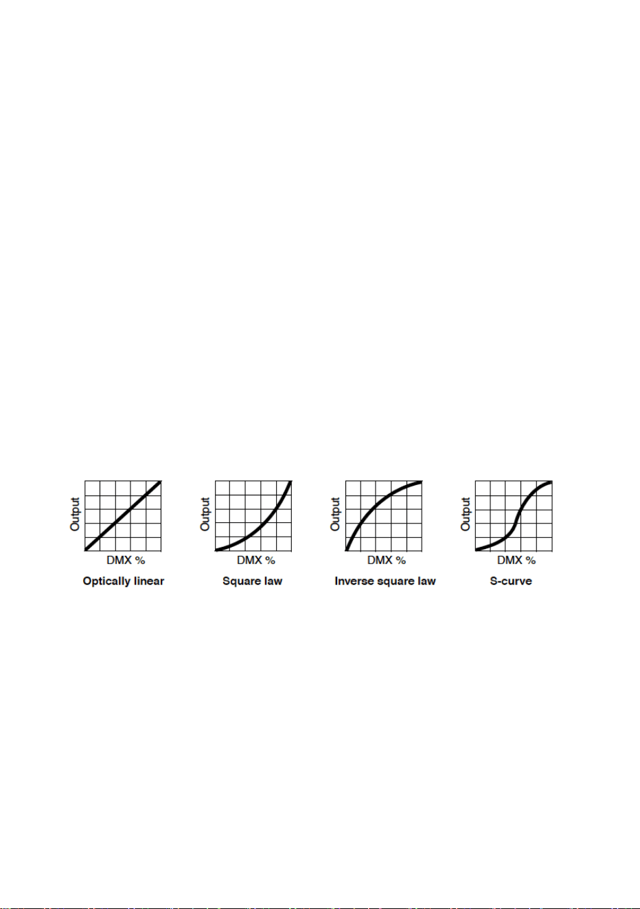
Dimming curves
Four dimming curves are available:
LINEAR – The increase in light intensity appears to be linear as DMX
value is increased.
SQUARE LAW – light intensity control is finer at low levels and coarser
at high levels.
INVERSE SQUARE LAW – light intensity control is coarser at low levels
and finer at high levels.
S-CURVE – light intensity control is finer at low levels and high levels
and coarser at medium levels.

Martin
®
ELP PAR User Guide 21
To set the fixture’s dimming curve:
1. Select DIMMER CURVE and press ENTER. The currently set dimming
curve mode will blink in the display.
2. Use the DOWN and UP buttons to select LINEAR, SQUARE LAW, INV
SQ LAW, or S-CURVE.
3. Press ENTER to confirm your choice (or press MENU to exit without
making a change).
Dimming speed and smoothness
You can optimize dimming to give either the fastest or the smoothest
changes in dimming levels. To optimize dimming:
1. Select DIMMING SPEED and press ENTER.
2. Use the DOWN and UP buttons to select FAST (dimmer optimized for
speed) or SMOOTH (dimmer optimized for smoothness).
3. Press ENTER to confirm your choice (or press MENU to exit without
making a change).
Blackout or Hold if DMX signal stops
You can decide how the fixture should behave if you are controlling the
fixture via DMX and then you stop sending the DMX data signal:
1. Select NO DATA MODE and press ENTER. The currently set mode will
blink in the display.
2. Using the DOWN and UP buttons, select BLACKOUT or HOLD to
decide how the fixture should respond if it stops receiving a DMX signal:
- If you select BLACKOUT, the fixture will black out
- If you select HOLD, the fixture will continue to show the effect that it
is displaying at the time.
3. Press ENTER to confirm your choice (or press MENU to exit without
making a change).
Scene capture
The SCENE CATCH menu lets you capture all the DMX values that the
fixture is currently receiving and save them as a ‘scene’ that you can choose
to play back each time the fixture power is cycled off and on or each time
that you carry out a reset.
Three scene capture controls are available:
• SCENE CATCH RECORD stores the currently displayed scene in the
fixture’s memory. Once you have captured a scene, the fixture keeps
that scene in memory even if you cycle power off and on again.

22 Martin
®
ELP PAR User Guide
• SCENE CATCH = ON sets the fixture to show the scene that is stored in
memory if the fixture stops receiving a DMX signal.
If the fixture receives a DMX control signal during scene playback, it will
immediately stop showing its saved scene. If fixture power is cycled off
and on again or if the fixture is reset, it will again show its saved scene.
• SCENE CATCH = OFF disables the scene playback function: the fixture
does not show the scene that is stored in memory.
Setting SCENE CATCH to OFF does not delete the saved scene from
memory: the scene will still be available if you set SCENE CATCH to ON
again.
Cooling mode
The cooling mode setting lets you decide whether to give priority to lowest
noise level or maximum light output:
1. Select COOLING MODE and press ENTER. The currently set mode will
blink in the display.
2. Using the DOWN and UP buttons, select one of the three cooling
options:
- If you select REGULATED FANS, the fans operate at normal speed.
Temperature regulation increases fan speed if the fixture
approaches its maximum operating temperature. This setting
provides a good compromise between low fan noise and powerful
light output.
- If you select THEATER MODE, the fans operate at lower speed.
Temperature regulation reduces maximum light output if the fixture
approaches its maximum operating temperature. This setting gives
priority to the lowest possible noise.
The THEATER MODE setting also increases the LED PWM
frequency to 19 200 Hz to ensure flicker-free high speed video
recording.
- If you select FULL, the fans operate at full speed without
temperature regulation. This setting maximizes cooling and gives
priority to the highest possible light output intensity. FULL fan mode
can also be used as a quick way of dislodging dirt from fans.
3. Press ENTER to confirm your choice (or press MENU to exit without
making a change).

Martin
®
ELP PAR User Guide 23
Display rotation
The fastest way to rotate the control panel display through 180° to match the
fixture’s orientation is to press and hold the UP button and then press the
DOWN button.
You can also rotate the display using the DISPLAY control menu:
1. Select DISPLAY → DISPLAY ROTATION and press ENTER.
2. Use the DOWN and UP buttons to select NORMAL (display in normal
orientation) or ROTATE 180° (display inverted to make it easier to read if
you install the fixture hanging vertically from its mounting bracket).
3. Press ENTER to confirm your choice (or press MENU to exit without
making a change).
Display intensity
To set the brightness of the control panel display:
1. Select DISPLAY → DISPLAY INTENSITY and press ENTER.
2. Use the DOWN and UP buttons to adjust the brightness of the display
from 10% to 100%.
3. Press ENTER to confirm your choice (or press MENU to exit without
making a change).
Temperature units
To set the fixture to display temperatures in degrees Celsius or Fahrenheit:
1. Select DISPLAY → TEMPERATURE UNIT and press ENTER.
2. Use the DOWN and UP buttons to select °C or °F.
3. Press ENTER to confirm your choice (or press MENU to exit without
making a change).
Resetting to factory defaults
To reset the fixture to its factory default settings:
1. Select FACTORY DEFAULT and press ENTER to confirm.
2. Use the DOWN and UP buttons to select YES to erase any custom
settings that you have configured and reset the fixture to its factory
default settings, or select NO.
3. Press ENTER to confirm your choice (or press MENU to exit without
making a change).

24 Martin
®
ELP PAR User Guide
Fixture test
You can run an automatic sequence to test all the fixture’s effects or
manually test individual effects using the control menus.
Automatic effects test
To perform a complete test of all of the fixture’s effects:
1. Select FIXTURE TEST → TEST ALL and press ENTER to confirm. The
automatic test will run.
2. To stop the test and return to the previous level of the menu structure,
press MENU.
Manual effects tests
You can also manually test individual effects.
To test LED dimming:
1. Select FIXTURE TEST → TEST DIMMER and press ENTER.
2. To stop the test and return to the previous level of the menu structure,
press MENU.
To test an individual effect:
1. Select FIXTURE TEST → TEST EFFECTS and press ENTER.
2. Use the DOWN and UP buttons to select RED, GREEN, BLUE, CTC,
COLOR (this tests the virtual color wheel effect), or ZOOM. Press
ENTER to confirm your selection. The fixture will now run an automatic
test of the selected effect.
3. Press MENU to exit the test and return to the list of effects.
Fixture information
Power on time
1. Select INFORMATION → POWER ON TIME and press ENTER to
display the total number of hours the fixture has been powered on since
it left the factory.
2. To return to the previous level of the menu structure, press MENU.
LED operating time
1. Select INFORMATION → LED HOURS and press ENTER to display the
total number of hours the LEDs have been activated since the fixture left
the factory.
2. To return to the previous level of the menu structure, press MENU.

Martin
®
ELP PAR User Guide 25
Firmware version
To see which software version is installed in the fixture:
1. Select INFORMATION → SW VERSION and press ENTER. The display
will indicate the currently installed firmware version.
2. Use the UP and DOWN buttons to scroll through firmware revisions.
3. To return to the previous level of the menu structure, press MENU.
Fixture ID number
You can set a custom 4-digit ID number for the fixture to help you identify it.
To manage the ID number:
1. Select INFORMATION → FIXTURE ID and press ENTER. The display
will indicate the current fixture ID number.
2. Use the DOWN and UP buttons to increase or decrease the current
fixture ID number until you reach the ID number that you want to allocate
to the fixture.
3. Press ENTER to confirm the new ID number (or press MENU to exit
without making a change).
RDM unique ID number
You can view the fixture’s unique non-resettable 12-digit RDM ID number.
To view the RDM UID number:
1. Select INFORMATION → RDM UID and press ENTER. The display will
indicate the fixture’s unique RDM ID number.
2. Press MENU to exit.
Fixture temperature readouts
To check the onboard temperature of the fixture:
1. Select INFORMATION → TEMPERATURES and press ENTER. The
fixture will display on two lines the current temperatures of the LED PCB
and of the PSU PCB.
2. To return to the previous level of the menu structure, press MENU.
Fan speed readouts
To view the current speed of each of the fixture’s cooling fans in RPM:
1. Select INFORMATION → FAN SPEED and press ENTER. The fixture
will display on two lines the current speeds in RPM of the LED PCB
cooling fan and of the PSU PCB cooling fan.
2. To return to the previous level of the menu structure, press MENU.

26 Martin
®
ELP PAR User Guide
DMX Live
You can view the DMX values currently being received on each of the
fixture’s DMX channels. This can be useful for troubleshooting purposes.
To view the DMX values being received:
1. Select DMX LIVE and use the UP and DOWN buttons to scroll through
the value being received on each channel.
2. To return to the previous level of the menu structure, press MENU.
Resetting the fixture
You can reset the entire fixture to return it to its state when you powered it
on, or you can reset its effects only.
• To carry out a full reset, select MANUAL CONTROL → RESET → ALL,
select YES or NO and press ENTER. The entire fixture will reset as if
you had cycled power. The reset process will take several seconds.
• To reset only the fixture’s effects, select MANUAL CONTROL → RESET
→ EFFECTS and press ENTER. The fixture’s effects will reset. The
effects reset process will take several seconds.
Manual control
You can control the fixture’s effects manually without needing a DMX signal.
This lets you set up a stand-alone scene.
To manually control the fixture:
1. Select MANUAL CONTROL and then use the UP and DOWN buttons to
scroll to the effect that you want to control. Press ENTER.
2. Use the UP and DOWN buttons to scroll to the DMX value from 000 to
255 that you want to send to that effect. Press ENTER to confirm and
send that value.
3. To return to the list of effects, press MENU.
4. If you want to manually control other effects together with the first effect,
repeat steps 1. and 2. and 3. above for the other effects. When you have
finished setting effects, return to the previous level of the menu structure,
by pressing MENU.
The fixture will continue to show the effects that you have set manually
until you set new manual control values for the effects. The effects are
unaffected by a power OFF/ON cycle: if you power the fixture off and on
again, it will resume showing the effects.
To stop the effects, open the DMX SETUP menu. This will immediately
stop all manually controlled effects.

Martin
®
ELP PAR User Guide 27
When in manual control mode, pressing any button on the control panel
lights up the control panel display and shows the message MANUAL
CONTROL MODE.
Focus shortcut
The fixture features a ‘focus shortcut’ mode that lets you adjust the zoom
effect. This can be useful if you are setting up multiple fixtures in the rig and
want to match the appearance of their projected beams.
To adjust the zoom effect:
1. Hold ENTER for two seconds. Focus shortcut mode is now enabled for
one minute. Light output switches to full white and zoom moves to
narrow
2. Use the UP and DOWN buttons to adjust the zoom effect for optimum
angle and position.
3. To return to the previous level of the menu structure, press MENU.
4. The fixture will keep its zoom adjustment setting until the next power
cycle.
DMX control is disabled while the fixture is in ‘focus shortcut’ mode.
Control / Settings DMX channel
The Control / Settings DMX channel lets you configure certain fixture
settings remotely via DMX. It gives access to many of the settings that are
available in the control menus (see the ‘Fixture setup’ chapter starting on
page 18) and it also gives access to Hibernation Mode (see below).
The control / settings functions require you to hold the required DMX value
for a certain number of seconds to implement them (see the DMX protocol
section on page 35).
Hibernation mode
Hibernation mode sets light output intensity to zero and disables effect
deployment.
The main purpose of this mode is to protect the fixture from the intake of
airborne material such as dust and confetti and to provide an option for
situations where noise is critical. The small reduction in power consumption
obtained in hibernation mode is not the mode’s main purpose.
When you bring the fixture out of hibernation mode, it performs a full reset.

28 Martin
®
ELP PAR User Guide
Effects
See the ‘DMX protocol’ section starting on page 35 for a full list of the DMX
channels and values required to control the different effects.
Shutter effect
The electronic ‘shutter’ effect provides instant open and blackout, variable
speed regular and random strobe.
Dimmer
Overall intensity can be adjusted 0-100% using smooth continuous
electronic dimming with 16-bit control resolution.
Custom colors
The fixture offers an RGB color mixing interface with 16-bit resolution in
Basic DMX Mode and 8-bit resolution in Compact DMX Mode. Colors are
obtained using RGBW LED output.
Color wheel effect
Besides color mixing, Basic DMX Mode features a virtual color wheel effect
with 48 preset colors. The virtual color wheel also provides variable speed
color scrolling and random colors.
Note that DMX commands sent on the virtual color wheel channel override
DMX commands sent on individual RGB color channels. This means that if
you want to use RGB color control on DMX channels 4 – 9, the color wheel
effect on channel 10 must be set to a DMX value from 0 to 10 (open
position).
The virtual color wheel follows the selected calibration mode (see ‘Raw,
extended and calibrated modes’ on page 20).
Color Temperature Control
The ELP PAR’s CTC channel lets you vary the color temperature of the
fixture’s white output from 1800 K to 12 850 K. The default color temperature
is 6000 K (which corresponds to DMX value 118 on the CTC channel).
If the fixture cannot reach some low CTC values, it clips at the lowest
achievable value (for example, DMX values 0-34 all give a color temperature
of 1800 K).
Note that CTC is disabled if you put the fixture into raw mode.

Martin
®
ELP PAR User Guide 29
Zoom
Zoom control via DMX lets you vary the field (one-tenth peak) angle from
5.6° to 57.6° and beam (half-peak) angle from 4.2° to 35.4°. 16-bit control is
available in Basic and Compact DMX Modes.

30 Martin
®
ELP PAR User Guide
RDM
The ELP PAR responds to the following RDM PIDs:
PID
Name
Description
GET
SET
0x0001
DISC_UNIQUE_BRANCH
Fixture discovery
N/A
N/A
0x0002
DISC_MUTE
Fixture discovery
N/A
N/A
0x0003
DISC_UN_MUTE
Fixture discovery
N/A
N/A
0x0020
QUEUED_MESSAGE
Get Queued Messages
Y
0x0030
STATUS_MESSAGES
Get Status/Error
Information
Y
0x0031
STATUS_ID_DESCRIPTION
Status/Error Description
Y
0x0032
CLEAR_STATUS_ID
Clear Status/Error Queue
Y
0x0050
SUPPORTED_PARAMETERS
Parameter discovery
Y
0x0051
PARAMETER_DESCRIPTION
Parameter discovery
Y
0x0060
DEVICE_INFO
Get basic info
Y
0x0080
DEVICE_MODEL_DESCRIPTION
Product Name
Y
0x0081
MANUFACTURER_LABEL
Manufacturer Name
Y
0x0082
DEVICE_LABEL
User-Changeable Label
Y
Y
0x0090
FACTORY_DEFAULTS
Reset to factory defaults
Y
Y
0x00C0
SOFTWARE_VERSION_LABEL
Firmware version
Y
0x00E0
DMX_PERSONALITY
DMX Mode
Y
Y
0x00E1
DMX_PERSONALITY_DESCRIPTION
DMX Mode Name
Y
0x00F0
DMX_START_ADDRESS
DMX Start Address
Y
Y
0x0121
SLOT_DESCRIPTION
DMX Channel Description
Y
0x0200
SENSOR_DEFINITION
Sensor Description
Y
0x0201
SENSOR_VALUE
Sensor Value
Y
Y
0x0400
DEVICE_HOURS
Fixture Hours
Y
Y
0x0405
DEVICE_POWER_CYCLES
Fixture Power Cycles
Y
Y
0x0500
DISPLAY_INVERT
Flip Display
Y
Y
0x0501
DISPLAY_LEVEL
Display Intensity
Y
Y
0x1000
IDENTIFY_DEVICE
Highlight Fixture in rig
Y
Y
0x1001
RESET_DEVICE
Warm/Cold Reset
Y
0x1020
PERFORM_SELFTEST
Self test
Y
Y

Martin
®
ELP PAR User Guide 31
0x1021
SELF_TEST_DESCRIPTION
Self test Description
Y
0x8001
DMX_RESET
Enable/Disable Fixt. Off via
DMX
Y
Y
0x8003
FIXTURE_ID
User-Changeable Fixture
Number
Y
Y
0x8004
COLOR_MODE
Set Color Mode
Y
Y
0x8301
EFFECT_SPEED
Set Effects Speed
Y
Y
0x8308
DISPLAY_ERRORS_ENABLE
Show Errors on Display
Y
Y
0x8310
DIMMER_CURVE
Set Dimmer Curve
Y
Y
0x8312
DISPLAY_AUTO_OFF
Display Auto Off
Y
Y
0x8329
HIBERNATION_MODE
Enable/Disable
Hibernation
Y
Y
0x832A
TUNGSTEN_MODE
Enable/Disable Tungsten
Mode
Y
Y
0x8603
FAN_CLEAN
Fan Clean Mode
Y
Y
0x8604
FAN_MODE
Fan Mode
Y
Y
0x8700
SERIAL_NUMBER
Read Serial Number
Y

32 Martin
®
ELP PAR User Guide
Maintenance
Read ‘Safety information’ on page 4 before servicing the
fixture.
Refer any service operation not described in this user manual
to a qualified service technician.
Disconnect the fixture from mains power and allow to cool
completely before cleaning or servicing.
Service fixtures in an area where there is no risk of injury from
falling parts, tools or other materials.
Cleaning
Excessive dust, smoke fluid, and particle buildup degrades performance,
causes overheating and will damage the fixture. Damage caused by
inadequate cleaning or maintenance is not covered by the product warranty.
The cleaning of external optical lenses must be carried out periodically to
optimize light output. Cleaning schedules for lighting fixtures vary greatly
depending on the operating environment. It is therefore impossible to specify
precise cleaning intervals for the fixture. Environmental factors that may
result in a need for frequent cleaning include:
• Use of smoke or fog machines.
• High airflow rates (near air conditioning vents, for example).
• Presence of cigarette smoke.
• Airborne dust (from stage effects, building structures and fittings or the
natural environment at outdoor events, for example).
If one or more of these factors is present, inspect fixtures within their first
100 hours of operation to see whether cleaning is necessary. Check again at
frequent intervals. This procedure will allow you to assess cleaning
requirements in your particular situation. If in doubt, consult your Martin
dealer about a suitable maintenance schedule.
Use gentle pressure only when cleaning, and work in a clean, well-lit area.
Do not use any product that contains solvents or abrasives, as these can
cause surface damage.
To clean the fixture:
1. Disconnect the fixture from power and allow it to cool for at least 15
minutes.

Martin
®
ELP PAR User Guide 33
2. Vacuum or gently blow away dust and loose particles from the outside of
the fixture and the air vents with low-pressure compressed air. Holding
cooling fan blades stationary with a screwdriver will protect them from
spinning too fast and possibly being damaged when you apply a vacuum
or air jet.
3. Clean lenses by wiping gently with a soft, clean lint-free cloth moistened
with a weak detergent solution. Do not rub the surface hard: lift particles
off with a soft repeated press. Dry with a soft, clean, lint-free cloth or
low-pressure compressed air. Remove stuck particles with an unscented
tissue or cotton swab moistened with glass cleaner or distilled water.
4. Check that the fixture is dry before reapplying power.
Uploading new firmware
Important! Do not switch the fixture off or disconnect the source of the
firmware during an update, or the firmware will be corrupted.
You can check the currently installed firmware version in the INFORMATION
menu. Firmware updates can be downloaded automatically from the Martin
cloud using the Martin Companion software suite on a PC connected to the
Internet.
Fixture information and settings are not affected when you upload new
firmware to the fixture. All ELP PAR fixtures that are powered on and
connected via a DMX link to the fixture that you update will also have their
firmware updated.
If you update firmware to a newer version, check the ELP PAR area of
www.martin.com to see whether an updated version of this User Guide is
available for the new firmware.
You need the following in order to install firmware:
• A Windows PC running the latest version of the Martin Companion
software suite that is available for download from the Martin website at
www.martin.com.
• The latest ELP PAR firmware files (Martin Companion automatically
downloads these from the Martin fixture firmware cloud when you run it
on a PC that is connected to the Internet).
• A Martin Companion Cable USB-DMX hardware interface (see
“Accessories” on page 49). Note that you can install new firmware in
multiple fixtures at the same time using the Martin Companion Cable.
To install the ELP PAR firmware using a Martin Companion Cable:
1. Apply power to the ELP PAR fixture(s) and allow it to boot

34 Martin
®
ELP PAR User Guide
2. Connect the Martin Companion Cable’s USB connector to a USB port on
your PC. Connect the Martin Companion Cable’s XLR connector to
either the fixture’s DMX IN connector or the DMX link.
3. Start the PC and launch Martin Companion. Check that the Martin
Companion application correctly detects the Martin Companion Cable (a
green dot should appear next to USB Connected in the top right-hand
corner of the window).
4. Locate the latest ELP PAR firmware in Martin Companion (Firmware →
ELP → ELP PAR).
5. Start the firmware update by clicking Update Firmware in Martin
Companion. Do not disconnect the Martin Companion Cable or power
off the fixture(s) until the upload is complete and the fixture(s) has
successfully rebooted.
6. If you are updating multiple fixtures over a DMX link, check that they
have all rebooted correctly.
Service and repairs
There are no user-serviceable parts inside the fixture. Do not open the
housing. The LED light source is not user-replaceable.
Refer any service or repair operation not described in this manual to an
authorized Martin service technician. Do not try to carry out such an
operation yourself, as doing so may present a health or safety risk. It may
also cause damage or malfunction, and it may void your product warranty.
Installation, on-site service and maintenance can be provided worldwide by
the Martin Professional Global Service organization and its approved
agents, giving owners access to Martin’s expertise and product knowledge
in a partnership that will ensure the highest level of performance throughout
the product’s lifetime. Please contact your Martin supplier for details.
Martin
®
ELP PAR User Guide 35
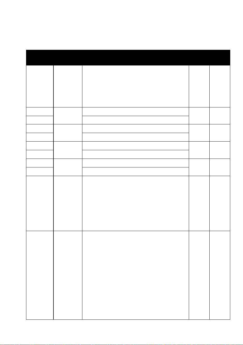
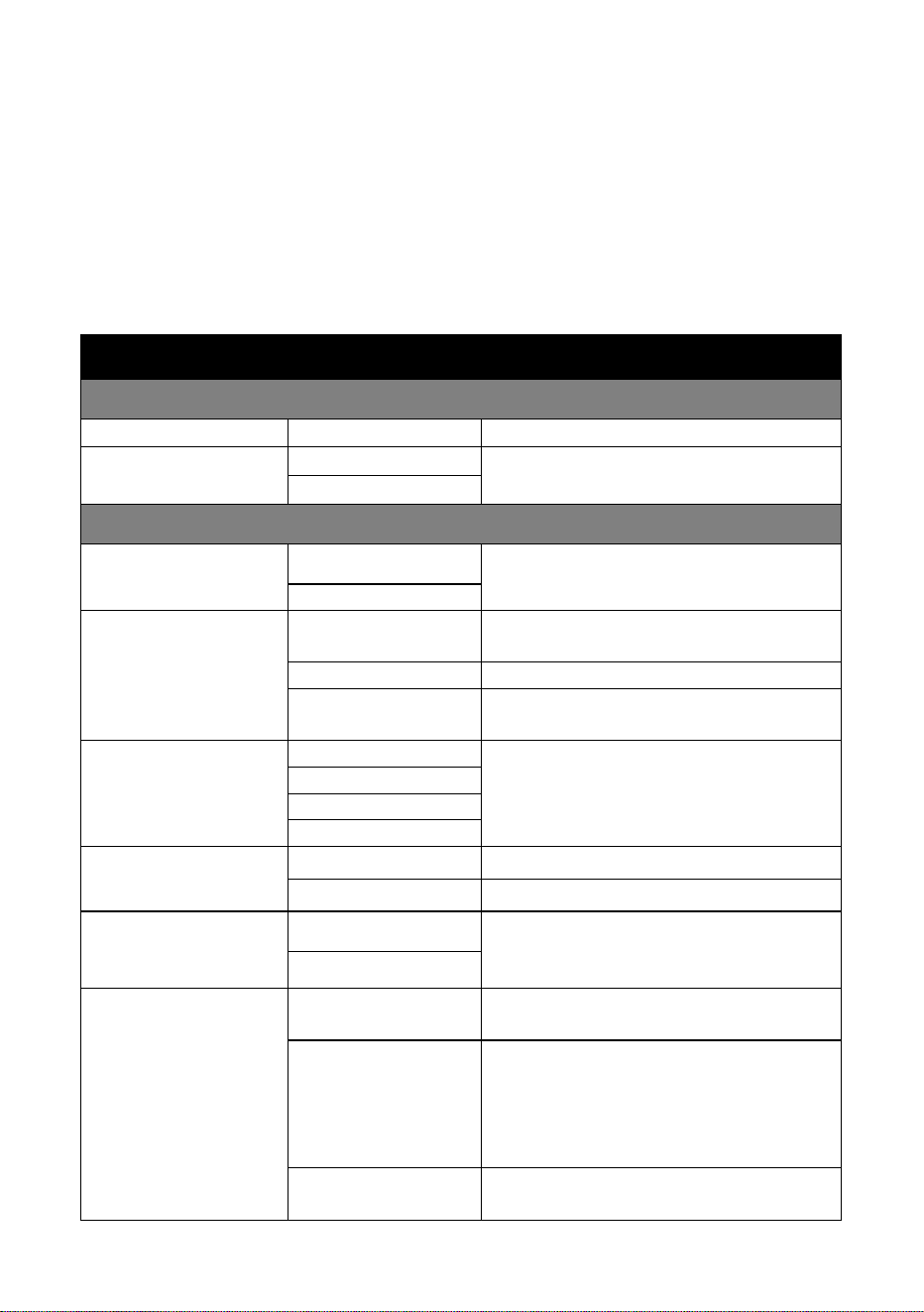
DMX protocol – Basic Mode (default)
DMX footprint: 14 channels
Channel
Value
Function
Fade
type
De-
fault
1
0-19
20-49
50-200
201-210
211-255
Strobe and shutter effects
Shutter closed
Shutter open
Strobe, slow → fast
Shutter open
Random strobe, slow → fast
Snap
30
2
0-65535
Dimming coarse 0 → 100%
Fade
0
3
Dimming fine
4
0-65535
Red coarse 0 → 100%
Fade
0
5
Red fine
6
0-65535
Green coarse 0 → 100%
Fade
0
7
Green fine
8
0-65535
Blue coarse 0 → 100%
Fade
0
9
Blue fine
10
0-34
…
118
…
128
…
255
CTC
1800 K
…
6000 K
…
6500 K
…
12 850 K
Fade
118
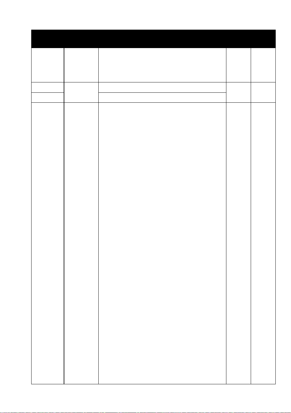
11
0-10
11-12
13-14
15-16
17-18
19-20
21-22
23-24
25-26
27-28
29-30
31-32
Color wheel effect (color presets)
Open (white)
Moroccan Pink (LEE 790)
Pink (LEE 157)
Special Rose Pink (LEE 332)
Follies Pink (LEE 328)
Fuchsia Pink (LEE 345)
Surprise Pink (LEE 194)
Congo Blue (LEE 181)
Tokyo Blue (LEE 071)
Deep Blue (LEE 120)
Just Blue (LEE 079)
Medium Blue (LEE 132)
Snap
0

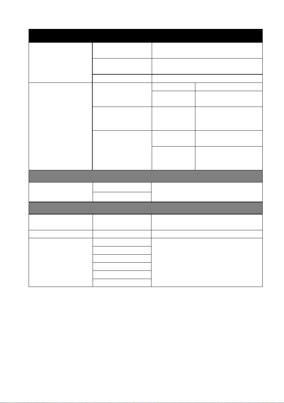
36 Martin
®
ELP PAR User Guide
Channel
Value
Function
Fade
type
De-
fault
11
(contd.)
33-34
35-36
37-38
39-40
41-42
43-44
45-46
47-48
49-50
51-52
53-54
55-56
57-58
59-60
61-62
63-64
65-66
67-68
69-70
71-72
73-74
75-76
77-78
79-80
81-82
83-84
85-86
87-88
89-90
91-92
93-94
95-96
97-98
99-100
101-102
103-104
105-106
107 - 190
191 - 214
215 - 219
220 - 243
Double CT Blue (LEE 200)
Slate Blue (LEE 161)
Full CT Blue (LEE 201)
Half CT Blue (LEE 202)
Steel Blue (LEE 117)
Lighter Blue (LEE 353)
Light Blue (LEE 118)
Medium Blue Green (LEE 116)
Dark Green (LEE 124)
Primary Green (LEE 139)
Moss Green (LEE 089)
Fern Green (LEE 122)
Jas Green (LEE 738)
Lime Green (LEE 088)
Spring Yellow (LEE 100)
Deep Amber (LEE 104)
Chrome Orange (LEE 179)
Orange (LEE 105)
Gold Amber (LEE 021)
Millennium Gold (LEE 778)
Deep Golden Amber (LEE 135)
Flame Red (LEE 164)
Red Magenta (LEE 113)
Medium Lavender (LEE 343)
Pure White (White LEDs only)
Pure Red (Red LEDs only)
Pure Yellow (Red+Green LEDs only)
Pure Green (Green LEDs only)
Pure Cyan (Green+Blue LEDs only)
Pure Blue (Blue LEDs only)
Pure Magenta (Blue+Red LEDs only)
Peacock Blue (LEE 115)
Dark Lavender (LEE 180)
Double CT Orange (LEE 287)
Full CT Orange (LEE 204)
Half CT Orange (LEE 205)
Deep Straw (LEE 015)
No function
Continuous rotation (color scroll)
Ascending, fast → slow
Stop (at current position)
Descending, slow → fast
Martin
®
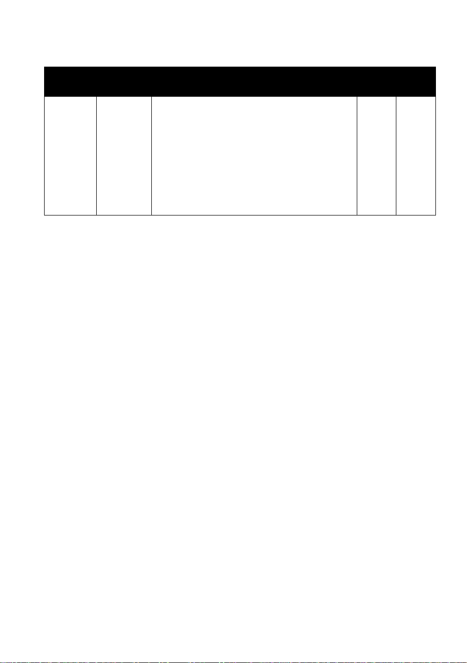
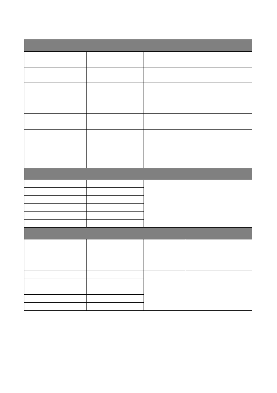
ELP PAR User Guide 37
Channel
Value
Function
Fade
type
De-
fault
11
(contd.)
244 - 247
248 - 251
252 - 255
Random colors
Random color, fast
Random color, medium
Random color, slow
Snap
0
12
0-65535
Zoom narrow → wide coarse 0 → 100%
Fade
32768
13
Zoom narrow → wide fine
14
0 - 9
10 - 14
15 - 16
17
18-22
23
24
25
26
27 - 30
31
32
33 - 37
38
39
40
41 - 51
52
53
54
55
56
57 - 60
61
62
63 - 71
72
73
74
75
76
77 - 99
Control / Settings
No function (disables calibration) – 5 s.
Reset fixture – 5 s.
No function
Reset beam – 5 s.
No function
Linear dimming curve – 1 s.
Square law dimming curve – 1 s.
Inverse square law dimming curve –1 s.
S-curve dimming curve – 1 s.
No function
Dimming speed = Fast – 1 s.
Dimming speed = Slow – 1 s.
No function
Extended color mode – 1 s.
Calibrated color mode – 1 s.
Raw color mode –1 s.
No function
Display ON –1 s.
Display OFF –1 s.
Regulated fan speed, fixed intensity
– 1 s.
Full fan speed, regulated intensity – 1 s.
Theater mode: reduced max. intensity,
low fan speed – 1 s.
No function
Hibernation mode = ON – 5 s.
Hibernation mode = OFF – 5 s.
No function
Tungsten emulation = ON – 1 s.
Tungsten emulation = OFF – 1 s.
Scene catch record – 5 s.
Scene catch playback = ON – 5 s.
Scene catch playback = OFF – 5 s.
No function
Snap
0
38 Martin
®
ELP PAR User Guide
Channel
Value
Function
Fade
type
De-
fault
14
(contd.)
100
101
102
103 - 113
114
115 - 198
199
200 - 255
Enable calibration – 5 s.
No function
Store dimmer calibration – 5 s.
No function
Store zoom calibration – 5 s.
No function
Reset ALL calibration settings to
factory defaults – 5 s.
No function
Martin
®
ELP PAR User Guide 39
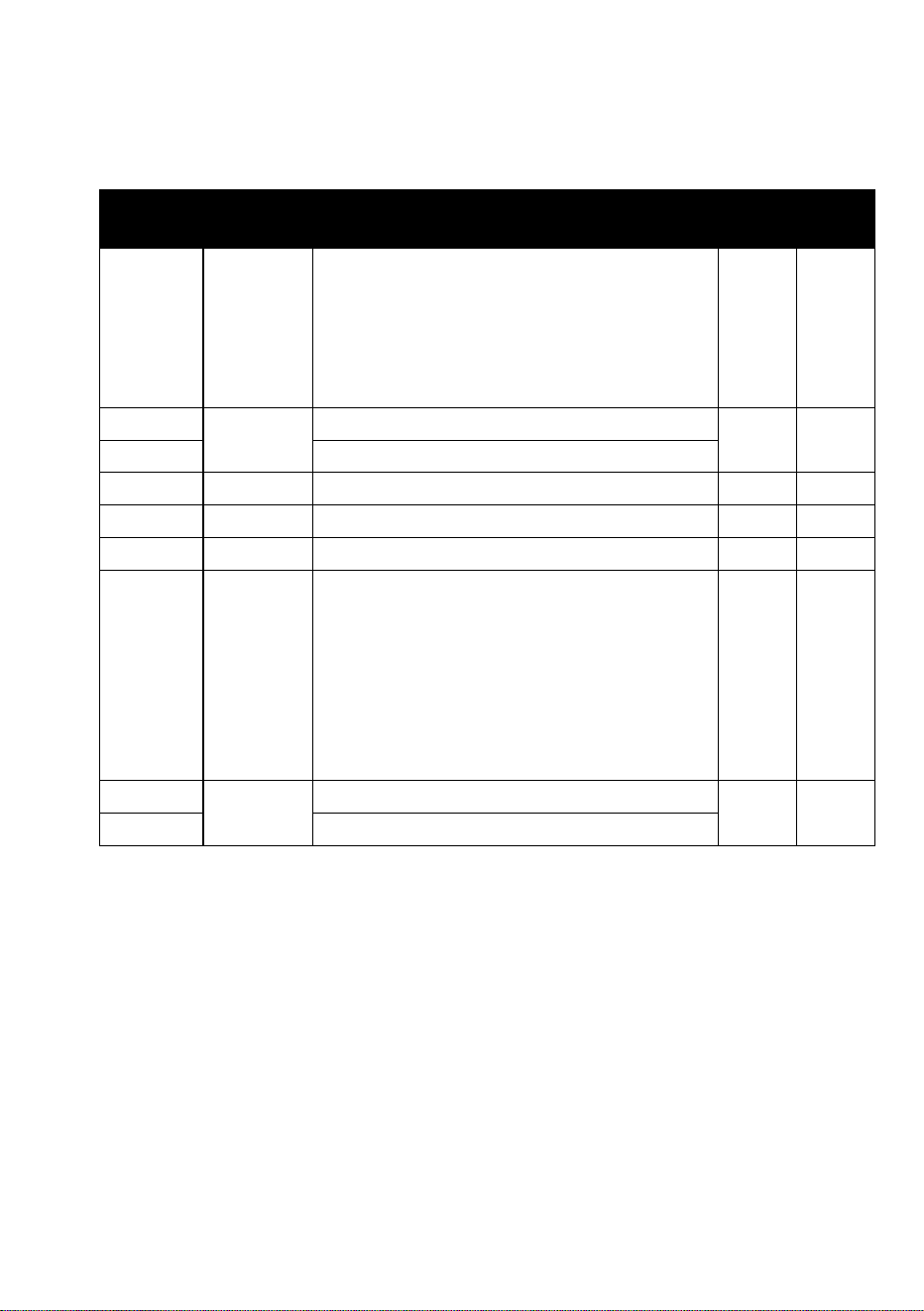
DMX protocol – Compact Mode
DMX footprint: 9 channels
Channel
Value
Function
Fade
type
De-
fault
1
0-19
20-49
50-200
201-210
211-255
Strobe and shutter effects
Shutter closed
Shutter open
Strobe, slow → fast
Shutter open
Random strobe, slow → fast
Snap
30
2
0-65535
Dimming coarse 0 → 100%
Fade
0
3
Dimming fine
4
0-255
Red 0 → 100%
Fade
0
5
0-255
Green 0 → 100%
Fade
0
6
0-255
Blue 0 → 100%
Fade
0
7
0-34
…
118
…
128
…
255
CTC
1800 K
…
6000 K
…
6500 K
…
12 850 K
Fade
118
8
0-65535
Zoom narrow → wide coarse 0→100%
Fade
32768
9
Zoom narrow → wide fine
40 Martin
®
ELP PAR User Guide
Control menus
To access the control menus, press the MENU button. Use the UP and
DOWN buttons to navigate the menus. Select any required menu option
using the ENTER button. For more information, see ‘Using the control
menus’ on page 18.
Default fixture settings are shown in bold.
Menu
Setting/value
Notes
DMX SETUP
DMX ADDRESS
001–499
Set fixture’s DMX address
DMX CONTROL
MODE
COMPACT
Set DMX control mode
BASIC
PERSONALITY
TUNGSTEN
EMULATOR
ON
Activate tungsten incandescent
lamp emulation mode
OFF
COLOR MODE
EXTENDED
COLOR
Calibrated white, uncalibrated
color
CALIBRATED
Calibrated white, calibrated color
RAW
UNCALIBRATED
Raw: uncalibrated white,
uncalibrated color
DIMMER CURVE
LINEAR
Dimming curve options
SQUARE LAW
INV SQ LAW
S-CURVE
DIMMING SPEED
FAST
Optimize dimmer for speed
SLOW
Optimize dimmer for smoothness
NO DATA MODE
BLACKOUT
Set fixture behavior if DMX signal
stops: blackout or hold current
effect
HOLD
SCENE CATCH
SCENE CATCH
RECORD
Saves all current DMX values as
playback scene
SCENE CATCH
ON
Sets fixture to run currently saved
playback scene after power cycle
or reset. Any new DMX input
disables scene playback until next
power cycle.
SCENE CATCH
OFF
Disables playback scene
functionality
Martin
®
ELP PAR User Guide 41
Menu
Setting/value
Notes
COOLING MODE
REGULATED
FANS
Fans normal, temperature-
regulated
THEATER
MODE
Fans low-noise, temperature-
regulated (reduced max. output)
FULL
Fans constant full speed
DISPLAY
DISPLAY
ROTATION
NORMAL
Normal orientation
ROTATE
180°
Inverted orientation
DISPLAY
INTENSITY
10 - 100
Control panel
display intensity in
%
TEMPERATURE
UNIT
°C
All temperature
readouts in Celsius
°F
All temperature
readouts in
Fahrenheit
DEFAULT SETTINGS
FACTORY
DEFAULT
NO
Return all fixture settings except
calibration to factory defaults
YES
FIXTURE TEST
TEST ALL
TESTING
Automatic test of all effects
including dimming
TEST DIMMER
DIMMER
Manually test LED groups only*
TEST EFFECTS
RED
Manually test individual effects*
COLOR = Virtual color wheel
GREEN
BLUE
CTC
COLOR
ZOOM
* Use UP & DOWN to scroll through LED groups or scroll through effects
and pause test, press ENTER to start test. Press MENU to exit test.
42 Martin
®
ELP PAR User Guide
INFORMATION
POWER ON TIME
xxxxH
Display hours fixture powered on
since manufacture
LED HOURS
xxxxH
Display hours LEDs powered on
since manufacture
SW VERSION
Vx.x.x
Display currently installed
firmware version
FIXTURE ID
0 - 9999
Display a user-settable 4-digit
fixture ID number
RDM UID
xxxxxxxxxxxx
Display the fixture’s unique RDM
ID number
TEMPERATURES
LED / BASE
Display temperatures of all PCBs
and the integrated PSU
FAN SPEED
LED / PSU
Display speeds in RPM of all
cooling fans including the PSU
cooling fan
DMX LIVE
STROBE
0 - 255
Scroll to display DMX values
currently being received on each
DMX channel from Strobe channel
to Control / Settings channel
DIMMER
0 - 255
DIMMER FINE
0 - 255
…
…
ZOOM FINE
0 - 255
FUNCTION
0 - 255
MANUAL CONTROL
RESET
ALL
NO
Reset entire fixture
YES
EFFECTS
NO
Reset effects only
YES
STROBE
0 - 255
Manually send DMX values on
each channel from Strobe channel
to Zoom fine control channel
DIMMER
0 - 255
DIMMER FINE
0 - 255
…
…
ZOOM FINE
0 - 255
Martin
®
ELP PAR User Guide 43
SERVICE
CALIBRATION
DIMMER
0 - 255
Calibrate overall
dimming and RGB
colors
RED
0 - 255
GREEN
0 - 255
BLUE
0 - 255
CTC
0 - 255
Adjust 6000 K
center point
CTC Tint
0 - 255
Adjust green/
magenta tint
RAW CTC
0 - 255
Adjust 6000 K
center point
RAW CTC Tint
0 - 255
Adjust green/
magenta tint
ZOOM
-128 - 127
Calibrate zoom
LOAD
DEFAULTS
LOAD
Load the factory
default calibration
settings
SAVE
Save current
custom calibration
settings.
Important! See
note below
SAVE SETTING
SAVE
Replace factory
default calibration
settings with
custom values
or zero values.
Important! See
note below
CLEAR ALL
VALUES
RESTORE
Reset all calibration
values to zero.
Important! See
note below
Important note
• LOAD DEFAULTS → SAVE stores any custom calibration values that
you have created in the CALIBRATION menu. The fixture will keep using
these values even when the fixture power is cycled off and on.
• LOAD DEFAULTS → LOAD loads the original factory default calibration
values (unless these have been overwritten or erased – see below)

44 Martin
®
ELP PAR User Guide
• CLEAR ALL VALUES → RESTORE erases all calibration settings – both
custom settings and the original factory settings. Important! If you use
this command you will need to fully recalibrate the fixture.
• Important! SAVE SETTING → SAVE permanently overwrites the
original factory settings with either the custom settings created
using LOAD DEFAULTS → SAVE or the zero values created using
CLEAR ALL VALUES → RESTORE. The SAVE SETTING → SAVE
command should normally be used by Martin Service only!

Martin
®
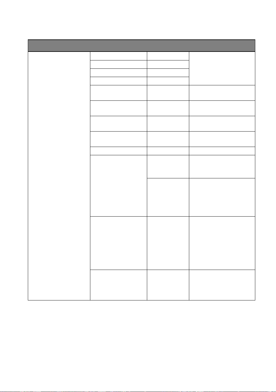
ELP PAR User Guide 45
Troubleshooting
This section describes a few common problems that may occur during
operation and provides some suggestions for easy troubleshooting:
Symptom
Potential cause
Remedies
No light from
fixture or fans not
working.
Power supply issue
such as faulty
connector, damaged
cable or internal fault.
Ensure that the mains
supply is connected and
supplying power to the
fixture. Check all power
connections and cables.
Contact your Martin
authorized distributor or
service center for
assistance.
One of the control
channels is
unresponsive or
only responds
intermittently.
DMX setup or DMX link
fault.
Faulty cable
connection.
Damaged zoom step
motor.
See next section.
Contact your Martin
authorized distributor or
service center for
assistance.
Fixture does not
respond to DMX
control.
Incorrect DMX
addressing.
Fault on DMX link due
to damaged connector
or cable, or potential
interference from
proximity to a high-
voltage installation.
Ensure that fixture’s DMX
address matches address
set on DMX control device.
Check all DMX cables and
connections.
Ensure that DMX link is
terminated.
Check that all components
on DMX link use standard
DMX polarity.
Attempt to control the fixture
with another DMX control
device.
Move or shield link if it is
close to an unshielded high-
voltage installation.
46 Martin
®
ELP PAR User Guide
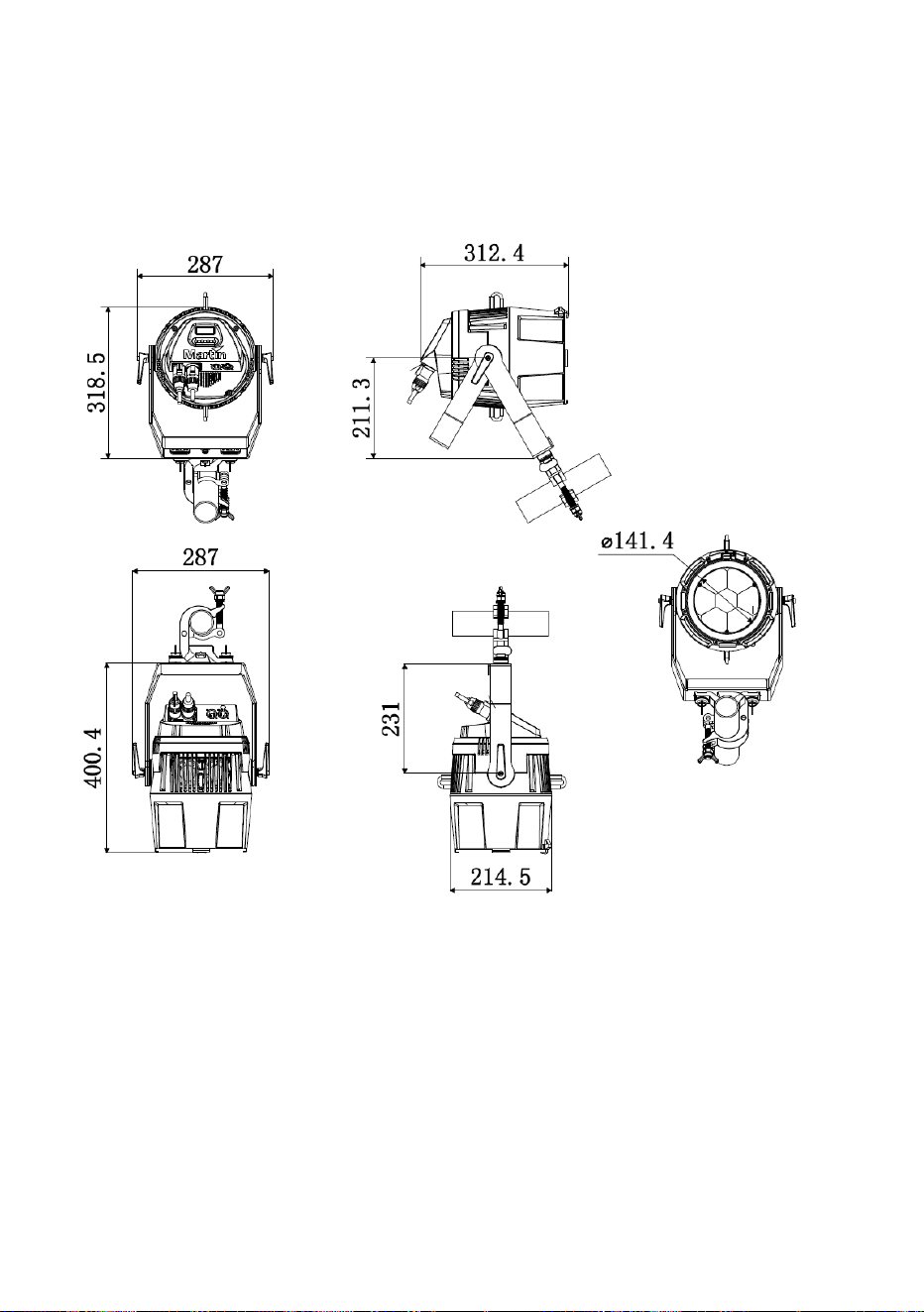
Dimensions
All dimensions are in millimeters

Martin
®
ELP PAR User Guide 47
Specifications
Physical
Dimensions incl. bracket (LxWxH) . 312x287x401 mm (12.3x11.3x15.8 in.)
Weight ............................................................................... 7.8 kg (17.2 lbs.)
Dynamic Effects
Color mixing ..................................................................................... RGBW
Color presets ........................... 48 color presets, virtual color wheel effects
Color temperature ............................................... Variable 1800 – 12 850 K
Electronic dimming ........................... 0 - 100%, four dimming curve options
Strobe and pulse effects .......... Variable speed and action, random strobe
Electronic 'shutter' effect .................................... Instant open and blackout
Zoom ............................................................................................ Motorized
Control and Programming
Control options .......................................................................... DMX, RDM
DMX channels ................. 14 (Basic DMX Mode), 9 (Compact DMX Mode)
16-bit fine control ............................ Dimming, RGB (in Basic Mode), Zoom
LED color management modes .................... Raw, extended and calibrated
DMX address setting ............................... Control panel with OLED display
DMX compliance ............................................................ USITT DMX512-A
RDM compliance ............................................................ ANSI/ESTA E1.20
Optics
Light source ................................................. 7 x 40 W RGBW Osram LEDs
Minimum LED lifetime ................ 50 000 hours (to >70% luminous output)*
Beam angle ................................................................................ 4.2 – 35.4°
Field angle .................................................................................. 5.6 – 57.6°
Cutoff angle ................................................................................ 6.2 – 65.1°
*Figure obtained under manufacturer´s test conditions
Construction
Filter mount .................................... PAR 46 – 191 x 191 mm (7.5 x 7.5 in.)
Color .................................................................................................... Black
Housing ............................................................... Aluminum and composite
Protection rating .................................................................................. IP 20
Installation
Mounting points ................................... Adjustable bracket, surface or truss
.............................................................. mount (fits Martin Omega Bracket)
Location .................. Not for household use, indoor use in dry location only
Orientation ............................................................................................. Any
Minimum distance to illuminated surfaces ................................ 1 m (3.3 ft.)
Minimum distance to combustible material ............................ 0.5 m (1.7 ft.)
Minimum clearance around fans and vents ........................... 0.5 m (1.7 ft.)
48 Martin
®
ELP PAR User Guide
Connections
AC power input ......................................... Neutrik powerCON TRUE1 TOP
AC power throughput ............................... Neutrik powerCON TRUE1 TOP
DMX data in/out ................................................... Neutrik 5-pin locking XLR
Electrical
AC power ....................................................... 100-240 V nominal, 50/60 Hz
Typical power consumption ............................................................... 300 W
Typical half-cycle RMS inrush current at 240 VAC ............................. 8.7 A
Power supply unit .............................. Auto-ranging electronic switch mode
Maximum power and current
100-120 V, 60 Hz ..................................... 3.0 A, 320 W, Power factor 0.99
220-240 V, 50 Hz ..................................... 1.7 A, 320 W, Power factor 0.94
*Measurements made at nominal voltage with all LEDs at full intensity.
Allow for a deviation of +/- 10%.
Thermal
Maximum surface temperature ............................................ 65° C (149° F)
Cooling ................................ Forced air (temperature regulated, low noise)
Maximum ambient temperature (Ta max.) ........................... 40° C (104° F)
Minimum ambient temperature (Ta min) ............................... -10° C (32° F)
Total heat dissipation* ............................................................ 1170 BTU/hr.
*Calculated, +/- 10%, at full intensity, full white
Approvals
Global CB Certification/IECEE ................... IEC 60598-2-17 (IEC 60598-1)
EU safety .................. EN 60598-2-17 (EN 60598-1), EN 62471, EN 62493
EU EMC.......................... EN 55015, EN 55032, EN 55035, EN 61000-3-2,
EN 61000-3-3, EN 61547
US safety ........................................................................................ UL 1573
US EMC...................................................................... FCC Part 15 Class B
Canadian safety ........................................................... CSA C22.2 No. 166
Canadian EMC ................................ ICES-003 Class B, ICES-005 Class B
Australia/NZ ......................................................................................... RCM
United Kingdom ................................................................................. UKCA
Environmental
RoHS ........................................................................................... Compliant
REACH ........................................................................................ Compliant
WEEE .......................................................................................... Compliant
Proposition 65 ............................................................................. Compliant

Martin
®
ELP PAR User Guide 49
Efficacy (max output)................................................................... 14.9 lm/W
LWR* .......................................................................... 449 lm/kg (204 lm/lb)
*LWR = Lumen-to-Weight Ratio
Included Items
Adjustable mounting bracket
Accessories
Power input cables, 16 A
Power Input Cable, H07RN-F, 2.5 mm2, bare ends to
TRUE1 NAC3FX-W (female), 1.5 m (4.9 ft.) ........................ P/N 91611797
Power Input Cable, H07RN-F, 2.5 mm2, bare ends to
TRUE1 NAC3FX-W (female), 5 m (16.4 ft.) ......................... P/N 91611786
Power Input Cable, SJOOW, 12 AWG, bare ends to
TRUE1 NAC3FX-W (female), 1.5 m (4.9 ft.) ........................ P/N 91610173
Power Input Cable, SJOOW, 12 AWG, bare ends to
TRUE1 NAC3FX-W (female), 5 m (16.4 ft.) ......................... P/N 91610174
Power relay cables, 16 A, for relaying power to fixtures in chains
Power Relay Cable, H07RN-F, 2.5 mm2,
TRUE1 to TRUE1, 0.45 m (1.5 ft.) ...................................... P/N 91611784
Power Relay Cable, H07RN-F, 2.5 mm2,
TRUE1 to TRUE1, 1.2 m (3.9 ft.) ......................................... P/N 91611785
Power Relay Cable, H07RN-F, 2.5 mm2,
TRUE1 to TRUE1, 2.5 m (8.2 ft.) ......................................... P/N 91611796
Power Relay Cable, SJOOW, 12 AWG,
TRUE1 to TRUE1, 0.45 m (1.5 ft.) ...................................... P/N 91610170
Power Relay Cable, SJOOW, 12 AWG,
TRUE1 to TRUE1, 1.2 m (3.9 ft.) ......................................... P/N 91610171
Power Relay Cable, SJOOW, 12 AWG,
TRUE1 to TRUE1, 2.5 m (8.2 ft.) ......................................... P/N 91610172
Power connectors
Cable Connector, Neutrik powerCON TRUE1
NAC3FX-W TOP (female) .............................................. P/N 91611789HU
Cable Connector, Neutrik powerCON TRUE1
NAC3MX-W TOP (male) ................................................. P/N 91611788HU
Installation hardware
Martin Omega bracket for rigging clamp attachment ........... P/N 91602001
Half-coupler clamp ............................................................... P/N 91602005
G-clamp (suspension vertically downwards only) ................ P/N 91602003
Quick-trigger clamp (suspension vertically downwards only)P/N 91602007
Safety Cable, SWL 60 kg, BGV C1 / DGUV 17, black ......... P/N 91604006
Safety Cable, SWL 60 kg, BGV C1 / DGUV 17, silver ......... P/N 91604007

50 Martin
®
ELP PAR User Guide
Related Items
Martin Companion software
suite (incl. firmware uploader) .......... Free download from www.martin.com
Martin Companion Cable
USB/DMX hardware interface .............................................. P/N 91616091
Ordering Information
ELP PAR in cardboard box .................................................. P/N 90800000
Specifications are subject to change without notice. For the latest product
specifications, see www.martin.com
Supplier’s Declaration of Conformity
Harman Professional, Inc. have issued an FCC Supplier’s Declaration of
Conformity for this product. The Declaration of Conformity is available for
download from the ELP PAR area of the Martin website at www.martin.com
FCC compliance statement
This equipment has been tested and found to comply with the limits for a
Class B digital device, pursuant to part 15 of the FCC Rules. These limits
are designed to provide reasonable protection against harmful interference
in a residential installation. This equipment generates, uses and can radiate
radio frequency energy and, if not installed and used in accordance with the
instructions, may cause harmful interference to radio communications.
However, there is no guarantee that interference will not occur in a particular
installation. If this equipment does cause harmful interference to radio or
television reception, which can be determined by turning the equipment off
and on, the user is encouraged to try to correct the interference by one or
more of the following measures:
• Reorient or relocate the receiving antenna.
• Increase the separation between the equipment and receiver.
• Connect the equipment into an outlet on a circuit different from that to
which the receiver is connected.
• Consult the dealer or an experienced radio/TV technician for help.

Martin
®
ELP PAR User Guide 51
Disposing of this product
Martin® products are supplied in compliance with Directive 2012/19/EC
of the European Parliament and of the Council of the European Union
on WEEE (Waste Electrical and Electronic Equipment), where
applicable. Help preserve the environment! Ensure that this product is
recycled at the end of its life. Your supplier can give details of local
arrangements for the disposal of Martin products


www.martin.com
