版 次 签 字 日 期
设 计
校 对
审 核
工 艺
标准化
批 准
更改文件号
印刷专用件
说明书
80g书写纸
宁波康韩瑞电器有限公司
共 1 张 第 1 张
06091644
阶段标记 质量 比例
1:1
翁文珊
2026.1.26
2026.1.26
2026.1.26
2026.1.26
2026.1.26
2026.1.26
焦森森
温清奎
陈城彬
姜朦朦
温清奎
空调说明书
技术要求
1.纸张边角应裁剪整齐、印刷字迹清晰整洁、内容正确,
没有明显的拖墨和重影等缺陷;
2.未注公差按GB/T1804C级;
3.版面为A5纸,黑白印刷;
4.字体颜色为黑色K100;
5.装订:骑马钉装订;
6.新品或版本更改后必需送样确认方可实施。
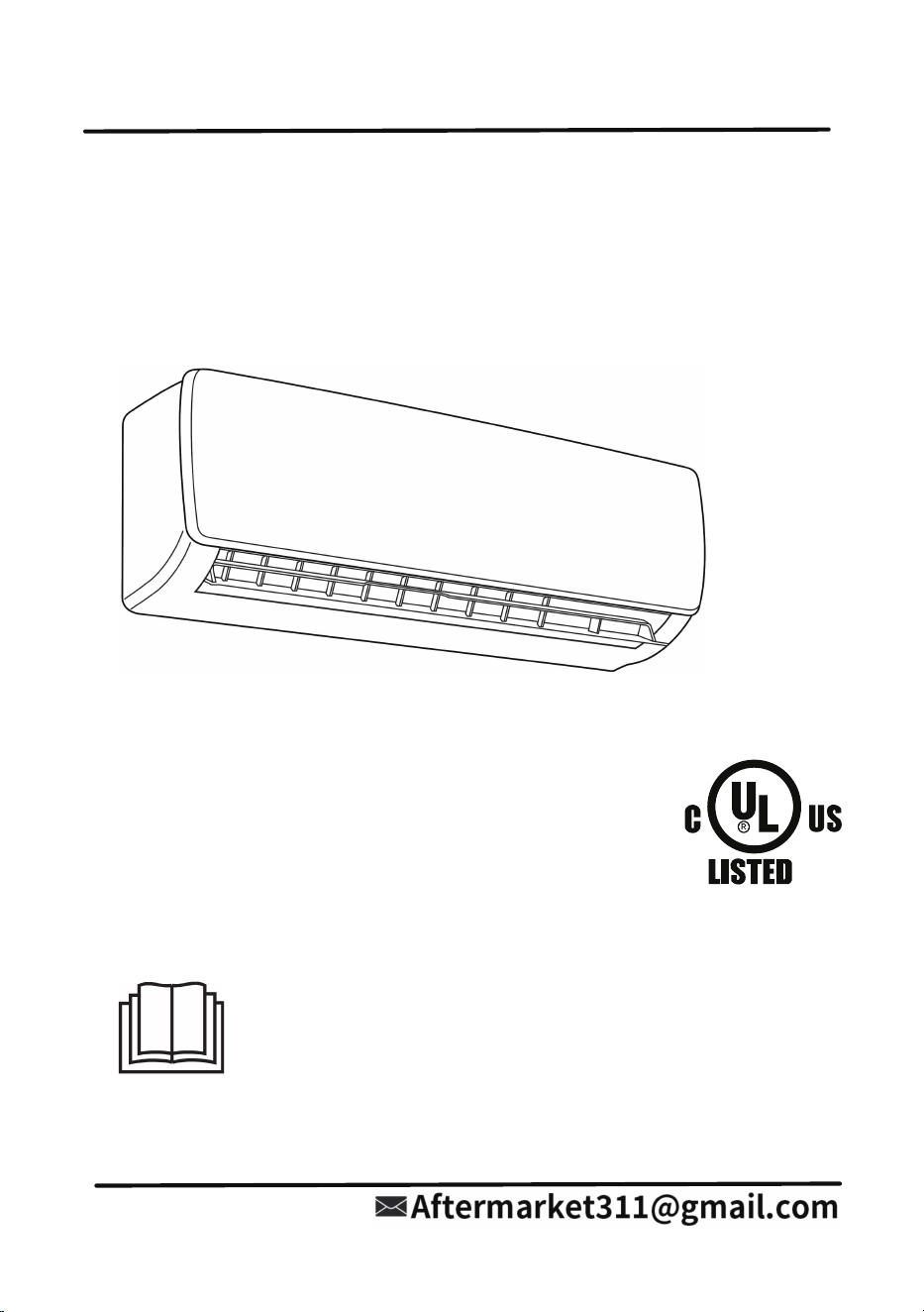
SPLIT-TYPE AIR CONDITIONER
Installation &
User’s Manual
HY9GWH115-1 / HY9GWH115-2
HY12GWH115-1 / HY12GWH115-2
HY12GWH230-1 / HY12GWH230-2
HY18GWH230-1 / HY18GWH230-2
HY24GWH230-1 / HY24GWH230-2
IMPORTANT NOTICE:
Read this manual carefully before installing or operating your new air
conditioning unit.
Be sure to save this manual for future reference
25
21-24
18-20
14-17
1
2-6
7-8
9
10-11
12-13
26
28
29-33
Indoor unit display
Remote Control
27
Remote Control Display
- 1 -
- 2 -
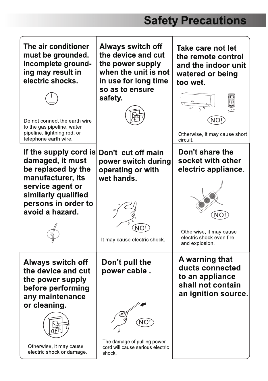
- 3 -
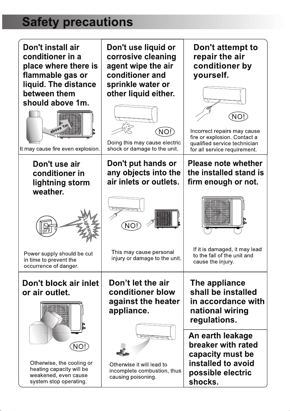
- 4 -
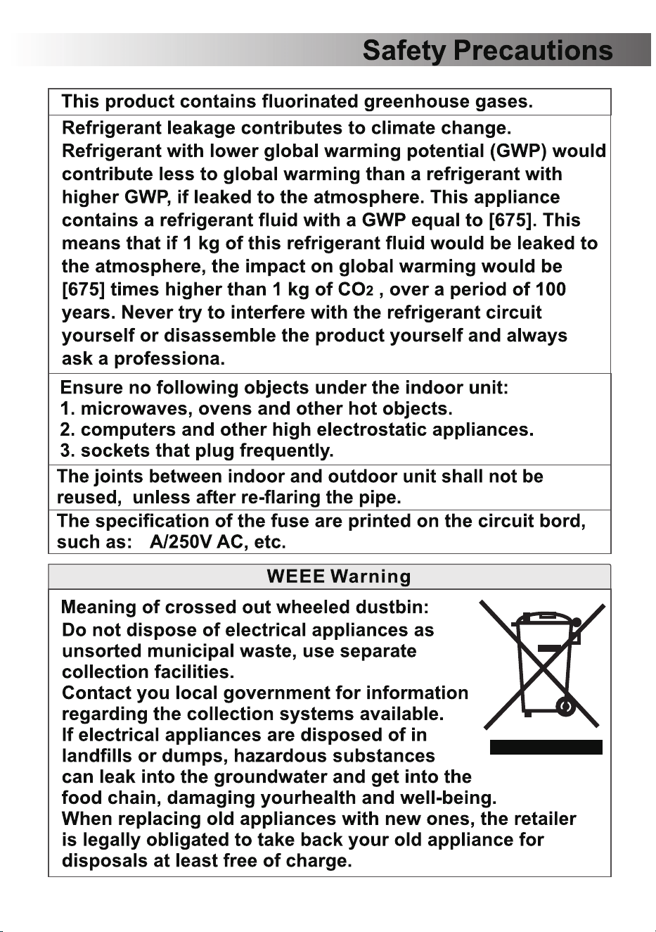
- 5 -
4
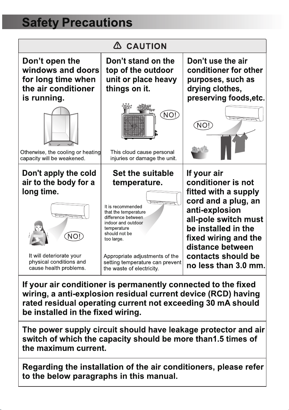
- 6 -
- 7 -
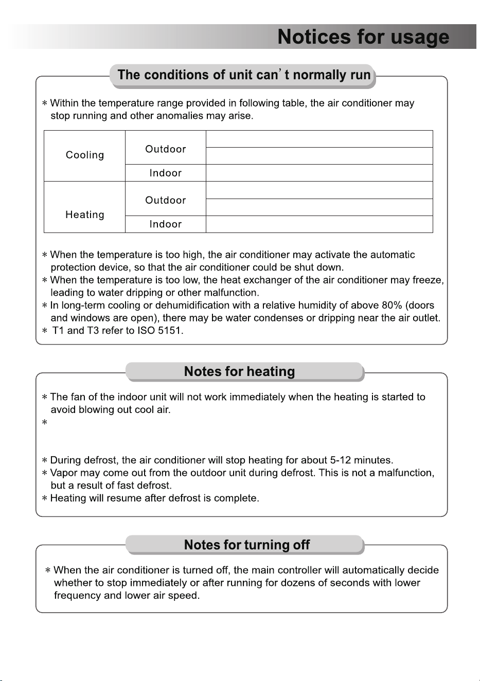
>43℃ (110℉) (Apply to T1)
>52℃ (126℉) (Apply to T3)
<18℃ (65℉)
>24℃ (76℉)
<-7℃ (19℉)
>27℃ (81℉)
When it is cold and wet outside, frost will form on the heat exchanger of the outdoor
unit, which reduces the heating efficiency. At this point, the air conditioner will activate
its defrosting function.
- 8 -
- 9 -
- 10 -
- 11 -
- 12 -
- 13 -
- 14 -
- 15 -
- 16 -
- 17 -
- 18 -
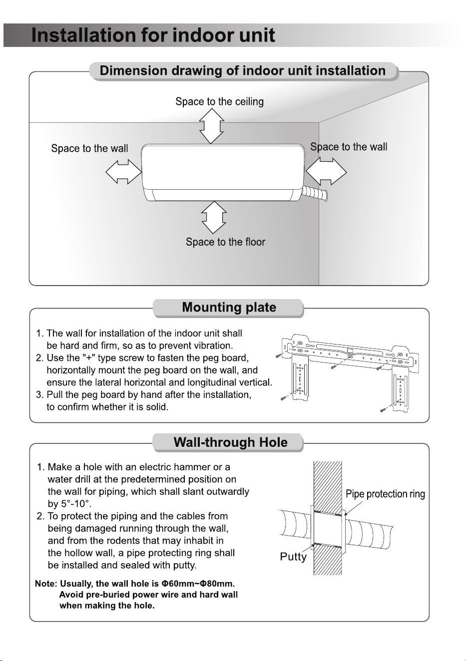
20cm above
(7.88in)
20cm above
(7.88in)
15cm above
(5.91in)
230-260cm
(90.56-102.37in)
- 19 -
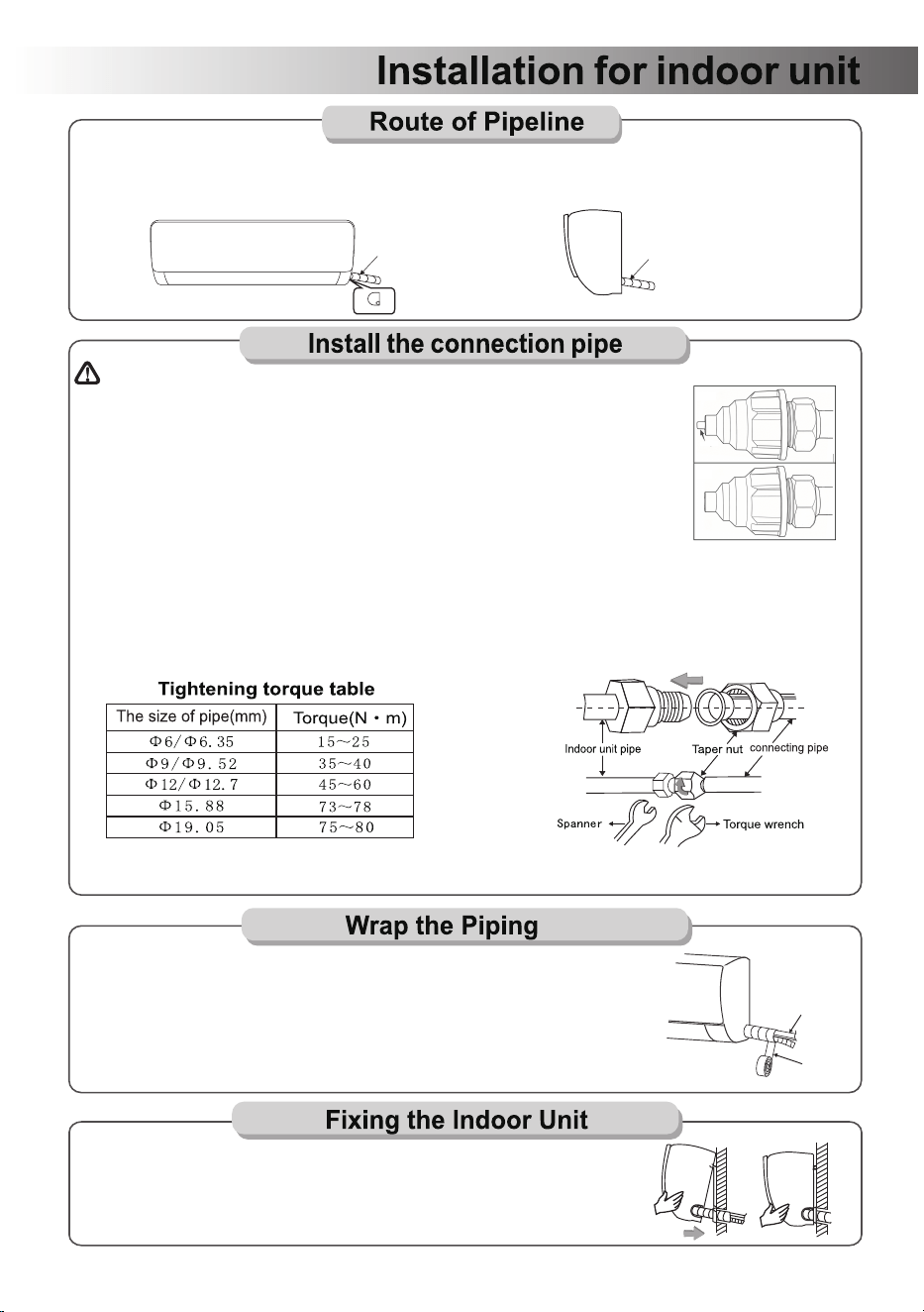
1.Depending on the position of the unit, the piping may be routed sideway from the left or the right
( Fig 1 ), or vertically from the back( Fig 2 )(depending on the pipe length of the indoor unit). In the
case of sideway routing, cut off the outlet cutting stock of the opposite side.
Connecting Pipe
Drain Hose
and Cables
Connecting Pipe
Drain Hose
and Cables
Connecting Pipe
Drain Hose
and Cables
Outlet material preparation
1.Remove the fixed part to pull out pipe of indoor machine from the case. Screw the hexagon nut in the
left of the joint to the end with your hand.
2.Connect the connecting pipe to the indoor unit: Aim at the pipe center, tighten the Taper nut with fingers,
and then tighten the Taper nut with a torque wrench, and the direction is shown in diagram on the right.
The torque used is shown in the following table.
Note: Carefully check if there is any damage of joints before installation.
The joints shall not be reused, unless after re-flaring the pipe.
IMPORTANT: If the unit with the quick connectors, please refer to the booklet of “Install the connection
pipe(the unit with the quick connectors)”.
Fig1 Fig2
1.Use the insulation sleeve to wrap the joint part the indoor unit and the
connection pipe, and then use insulating material to pack and seal
insulation pipe, to prevent generation of condensate water on the joint part.
2.Connect the water outlet with drain pipes, and make the connection
pipe, cables, and the drain hose straight.
3.Use plastic cable ties to wrap the connecting pipes, cables and drain
hose. Run the pipe sloping downward.
Plastic Strap
1.Hang the indoor unit on the peg board, and move the unit from left to
right to ensure that the hook is properly positioned in the peg board.
2.Push toward the lower left side and the upper right side of the unit
toward the peg board, until the hook is embedded in the slot and
makes a "click" sound.
The indoor unit of this product is factory-charged with nitrogen for pipeline sealing
and pressure retention. A red pressure indicator pin is installed at the pipeline
connection port.
Inspect the pin status BEFORE installation:
A protruded/extended pin confirms normal pipeline pressure with no leakage,
and the unit is safe for installation.
A recessed/non-protruded pin indicates nitrogen leakage and pipeline defects.
DO NOT INSTALL THE UNIT. Stop all operations immediately and contact after-
sales service for replacement or repair.
PRE-INSTALLATION CHECK: NITROGEN PRESSURE RETENTION PIN INSPECTION
GOOD
red pin
BAD
- 20 -
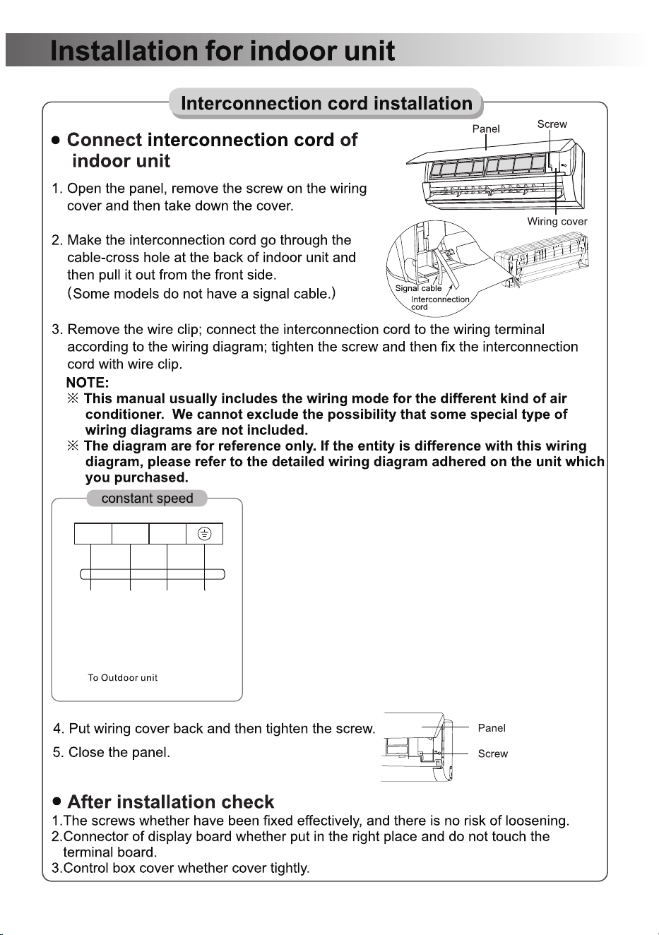
1 2 3

- 21 -
HY12GWH115-1/-2
HY9GWH115-1/-2
HY12GWH230-1/-2
HY18GWH230-1/-2
30cm
(11.82in)
200cm
(78.74in)
50cm
(19.69in)
50cm
(19.69in)
10cm
(3.94in)
780(830)x602x310mm
715(755)x502x250mm
520mm
20.47in
451mm
17.76in
328mm
12.91in
265mm
10.43in
30.71(32.68)x23.7x12.2in
28.15(29.72)x19.76x9.84in
HY24GWH230-1/-2
902(960)x652x320mm
623mm
24.53in
347mm
13.66in
35.51(37.8)x25.67x12.6in
Model
- 22 -
MODEL Rated voltage Frequency
HY12GWH115-1/-2
HY9GWH115-1/-2
HY12GWH230-1/-2
HY24GWH230-1/-2
HY18GWH230-1/-2
115V~ 60Hz
115V~ 60Hz
60Hz
60Hz
208-230V~
208-230V~
60Hz208-230V~
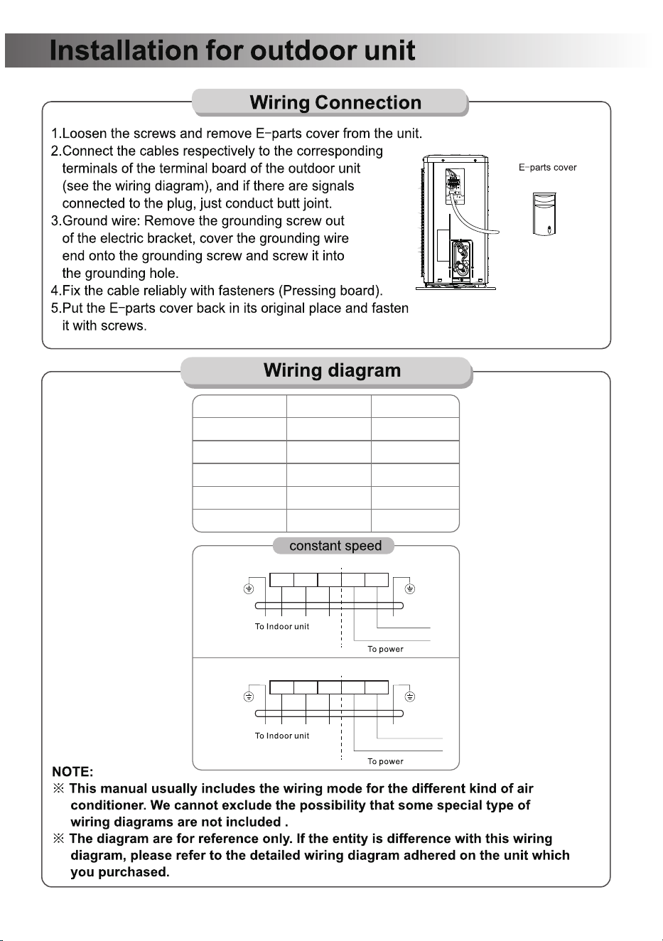
1 2 3 L N
1 2 3 L1 L2
115V hot wire
Neutral wire
115V hot wire L1
115V hot wire L2
115V Outdoor Unit
230V Outdoor Unit
- 23 -
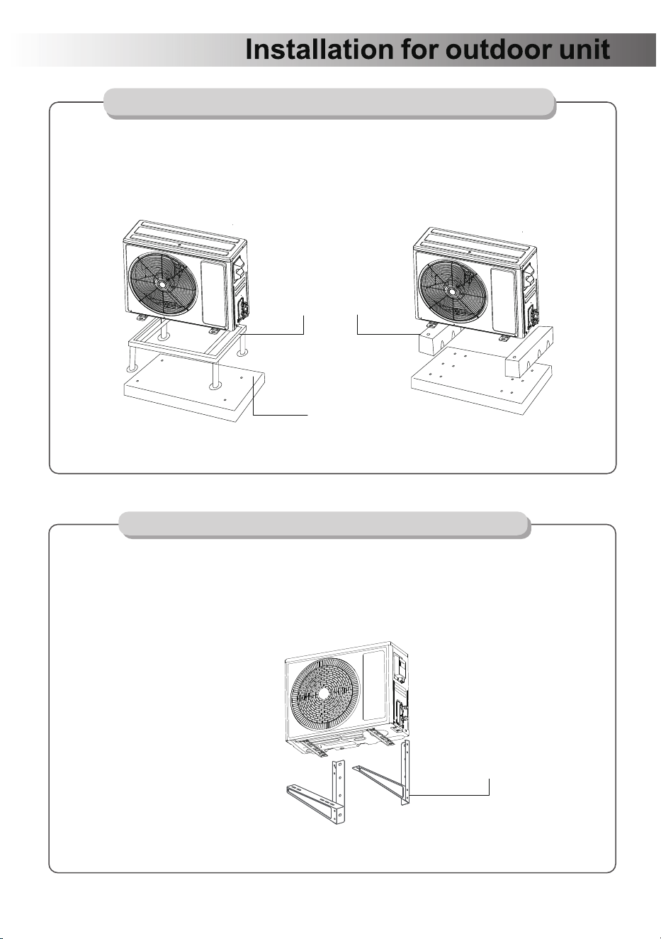
1.Place a concrete pad on the installation location.
2.Mount the outdoor unit in a base kit or stand.
3.Drill holes on the concrete pad.
4.Secure the base kit or stand on the concrete pad with concrete anchor bolts.
Secure the Outdoor Unit (Ground Installation)
NOTE:
Rubber foot pads can be placed between the outdoor unit and the mounting kit to
reduce vibrations and noise.
Secure the Outdoor Unit (Wall Installation)
The outdoor unit can be fixed on a wall mounting bracket if there is no ground
mounting option.
1. Measure the distance between the outdoor unit's legs.
2. Mount the wall mounting bracket on the wall.
3. Secure the outdoor unit on the wall mounting bracket.
NOTE:
The wall mounting bracket and the wall must be able to support at least 4 times
the weight of the outdoor unit, or 441lb, whichever is heavier.
Mounting Stand / Base Kit
(Not included)
Concrete Pad (Not included)
Wall Mount Bracket
(Not included)
- 24 -
19
(some products)
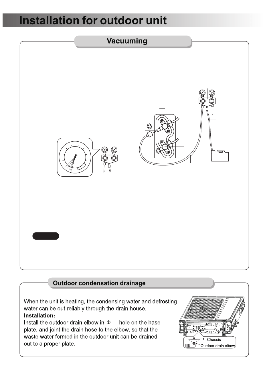
1. Remove the protective cap from the service port, low-pressure valve, and
high-pressure valve.
2. Connect the pressure hose from the manifold gauge to the service port.
3. Connect the charge hose from the manifold gauge to the vacuum pump.
4. OPEN the low-pressure valve (Lo·M) and
CLOSE the high-pressure valve (Hi·M) on
the manifold gauge.
5. Turn on the vacuum pump to vacuum
the system.
6. Let the vacuum pump run for at least
15 minutes and make sure the gauge
indicates -0.1Mpa(-76cmHg).
7. Close the pressure valve (Lo·M) and turn off the vacuum pump.
8. Leave the system connected with the manifold gauge for 5 minutes, then make sure
the gauge indication does not exceed 0.005Mpa.
*In the case of a leak, and the pressure value increases, reconnect all the connection
joints on the refrigerant line, and redo the vacuum pumping.
9. Open the high-pressure valve (Hi·R) for 1/4 turn, then close the valve after 5 seconds.
10. Check all the connection joints with a refrigerant leak detector or liquid leak detector.
11. Add refrigerant charge if you use a lengthened refrigerant line.
12. Disconnect the pressure hose from the service port, then fully open the low-pressure
valve (Lo·R) and high-pressure valve (Hi·R).
13. Put the protective caps back on the service port, low-pressure valve, and
high-pressure valve.Tighten the caps.
Charge Hose
Vacuum Pump
High Pressure
Valve(Hi·M)
Low Pressure
Valve(Lo·M)
Manifold Gauge
Pressure Hose
Low Pressure
Valve(Lo·R)
High Pressure
Valve(Hi·R)
Service Port
0
1
2
3
4
5
6
7
8
-0.1
Mpa
Page 21
- 25 -
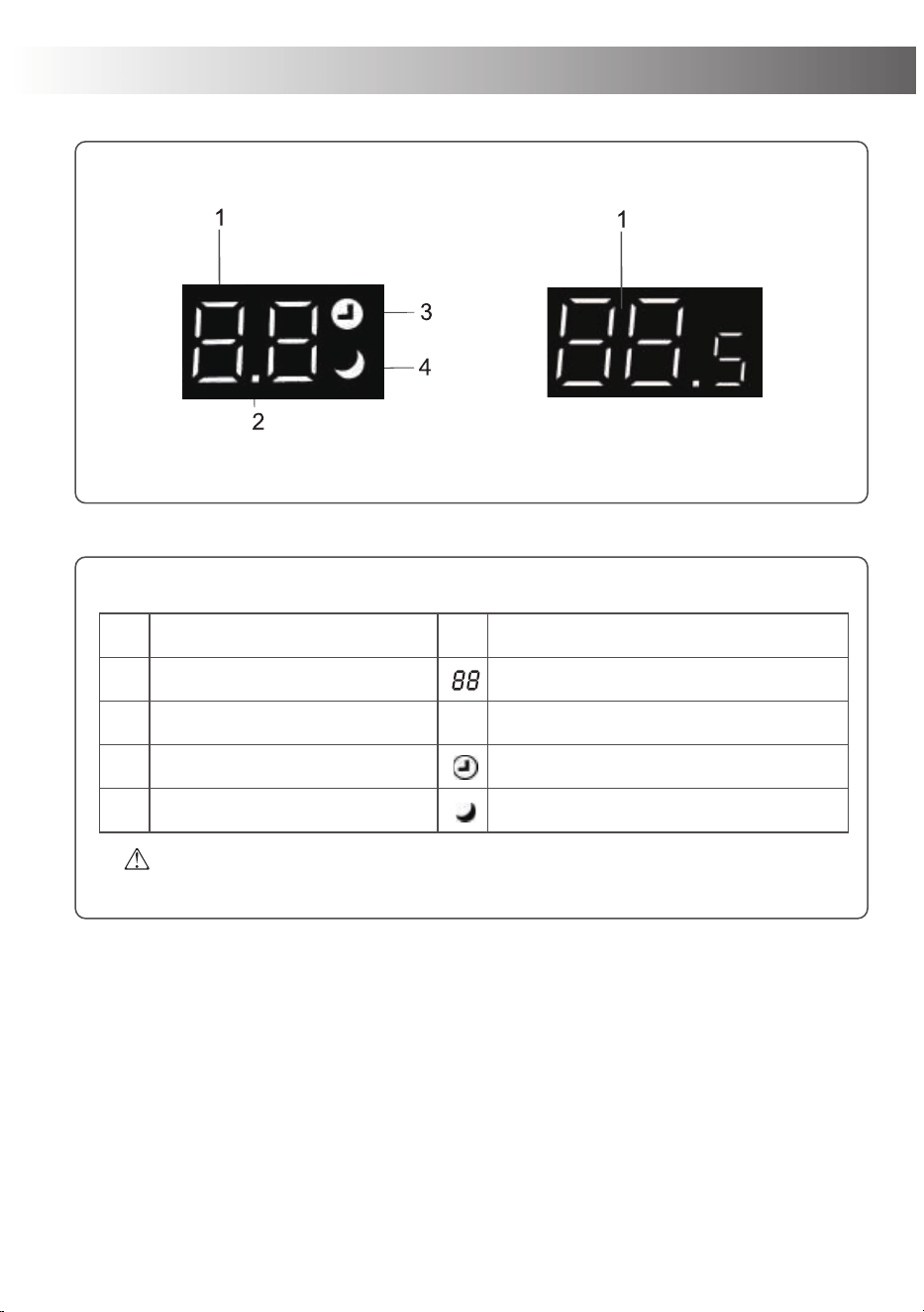
Indoor unit display
The shape and position of switchesand indicators may vary according to the
model, but their function is the same.
No.
1
2
3
4
Led Function
Temperature display(if present)
TIMER light/same NO.1
TIMER TIMER mode
SLEEP SLEEP mode
Indicates the set temperature in ℃ or ℉
TIMER mode light/same NO.1
- 26 -
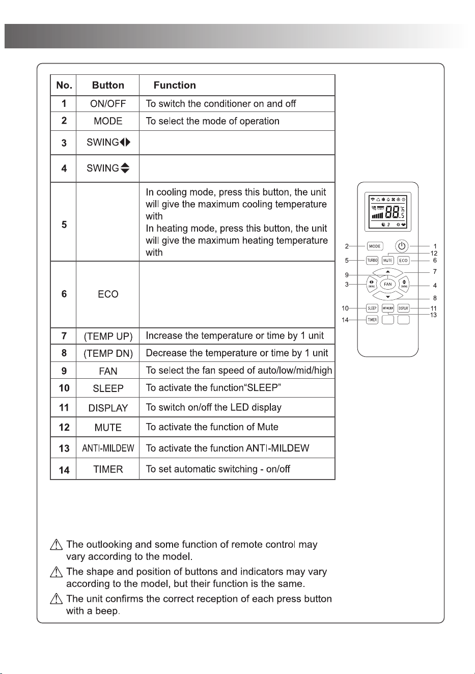
Remote Control
61℉(16℃)
88℉(31
TURBO
℃)
Activate function Swing horizontally
Activate function Swing vertical
ECO
In ECO mode, the air conditioner may
appropriately restrict its cooling or heating
capacity to achieve energy efficiency, but it
can generally still meet basic temperature
regulation needs
- 27 -
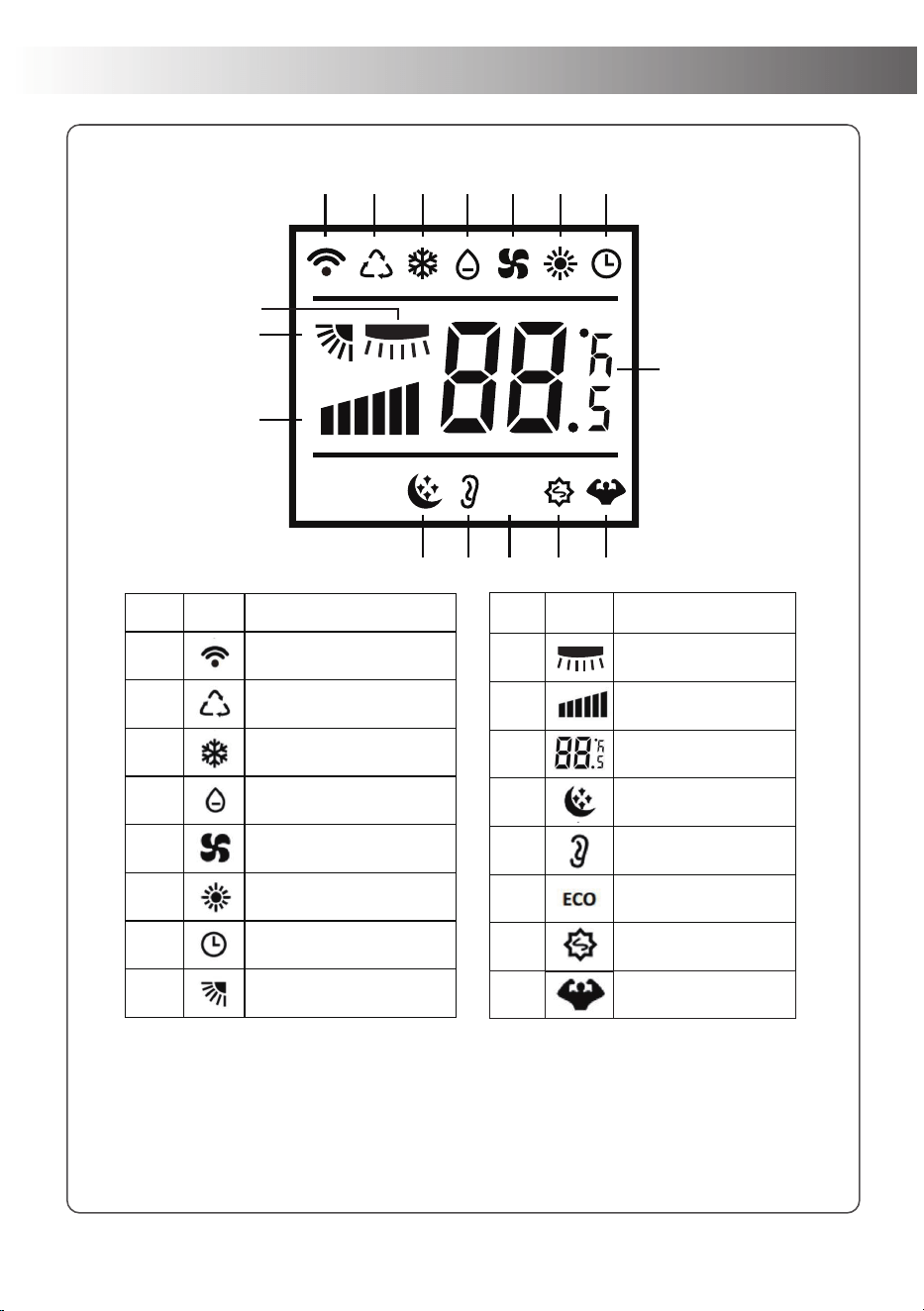
Remote Control Display
NOTE:
1. All indicators shown in the figure are for the purpose of clear presentation.
But during the actual operation only the relative functional signs are shown on
the display window.
2. Appearance of the display and function of the remote control may differ
from some models.
NO. Icon Description
1
Signal Transmission
2
Automatic Mode
3
Cool Mode
4
Dehumidification Mode
5
Fan Only Mode
6
Heat Mode
7
Timer Function
8
Up-Down Louver Swing
NO. Icon Description
9
Wind Speed Gear
Display
10
Set Temperature/
timer display
11
Sleep Mode
12
Mute Mode
13
ECO Mode
14
Anti-Mildew Mode
15
16
Turbo Mode
ECO
1
8
9
10
12 13 14 15 16
11
2 3 4 5 6 7
left-right Louver
Swing
- 28 -
- 29 -
- 30 -
- 31 -
- 32 -
- 33 -

If you encounter any problems when
using our products, please feel free to
contact us through the following Email
to get a quick response and a 100%
satisfactory solution.
Questions or Problems?
Tell us
We are here
to help with
our 100%
satisfactory service
within 24 hours
Email: Aftermarket311@gmail.com
MADE IN CHINA