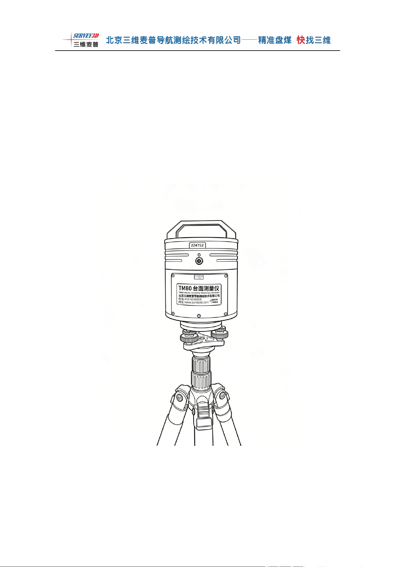
TM80 Countertop Measuring
Instrument
User Manual

Table of Contents
Important Notice ................................................................................. 2
Declaration .......................................................................................... 3
Chapter 1 Hardware Description ........................................................ 4
1 Instrument Checklist ..................................................................5
2 Specifications .............................................................................6
Chapter 2 Tabletop Measurement Software Description ................... 8
Chapter 3 Operating Procedure ......................................................10
1、 Unboxing and Assembly .................................................... 10
2 Connection ............................................................................... 11
2 Prepare for Measurement ........................................................ 15
3 Start Measurement ...................................................................15
Chapter 4 How to Modify the Ranging Difference .......................... 49
Chapter 5 Advanced Features for Other Surveying Industries
(Reference When Needed) ................................................................52
1 Station Setup ............................................................................52
2 Orientation ............................................................................... 53
3 Measurement ............................................................................55
Chapter 6 Product Warranty ............................................................. 56

第 2 页 共 57 页
Important Notice
Dear User,
Thank you for purchasing and using the product of BEIJING SAM SURVEYING
AND MAPPING TECHNOLOGY CO., LTD.For your safety and interests, please read
this user manual and all accompanying materials carefully before using this product.
Beijing Sanwei Maipu Navigation Surveying Technology Co., Ltd. shall not be held
liable for any personal injury, property damage, or other losses caused by failure to
follow the user manual instructions.
If you have any questions or objections regarding the contents of this manual,
please submit a written objection to Beijing Sanwei Maipu Navigation Surveying
Technology Co., Ltd. within seven days of receiving the instrument. Otherwise, it shall
be deemed that you have understood, agreed to, and accepted all contents of this manual.
If you encounter any problems during use, please feel free to contact us:
Pre-sales and after-sales consultation hotline: 010-62381808
Service hours: 7 days/week, 9 hours/day, 8:30-17:30
24-hour service phone: 18511635101 (Manager Zhang)
Beijing Sanwei Maipu Navigation Surveying Technology Co., Ltd. reserves the
right to interpret and modify this user manual. Any modifications, updates, or
interpretations to the manual will be published on the company's website
(www.survey3d.com). Please stay informed.
Thank you!
BEIJING SAM SURVEYING AND MAPPING TECHNOLOGY CO., LTD.

第 3 页 共 57 页
Declaration
Copyright Notice
This manual (including all photographs, illustrations, and software) is protected
by copyright law. All rights are reserved. This manual and all information contained
herein may not be reproduced without the written permission of the author.
Copyright ® BEIJING SAM SURVEYING AND MAPPING TECHNOLOGY
CO., LTD.Disclaimer
The information in this document is subject to change without notice. The
manufacturer makes no representations or warranties regarding the contents herein and
expressly disclaims any implied warranties of merchantability or fitness for any
particular purpose. The manufacturer reserves the right to revise this publication and to
make changes to the content from time to time without notice to any person.
Trademarks
All product names used in this manual are the property of their respective owners
and are used with acknowledgment.
第 4 页 共 57 页
Chapter 1 Hardware Description
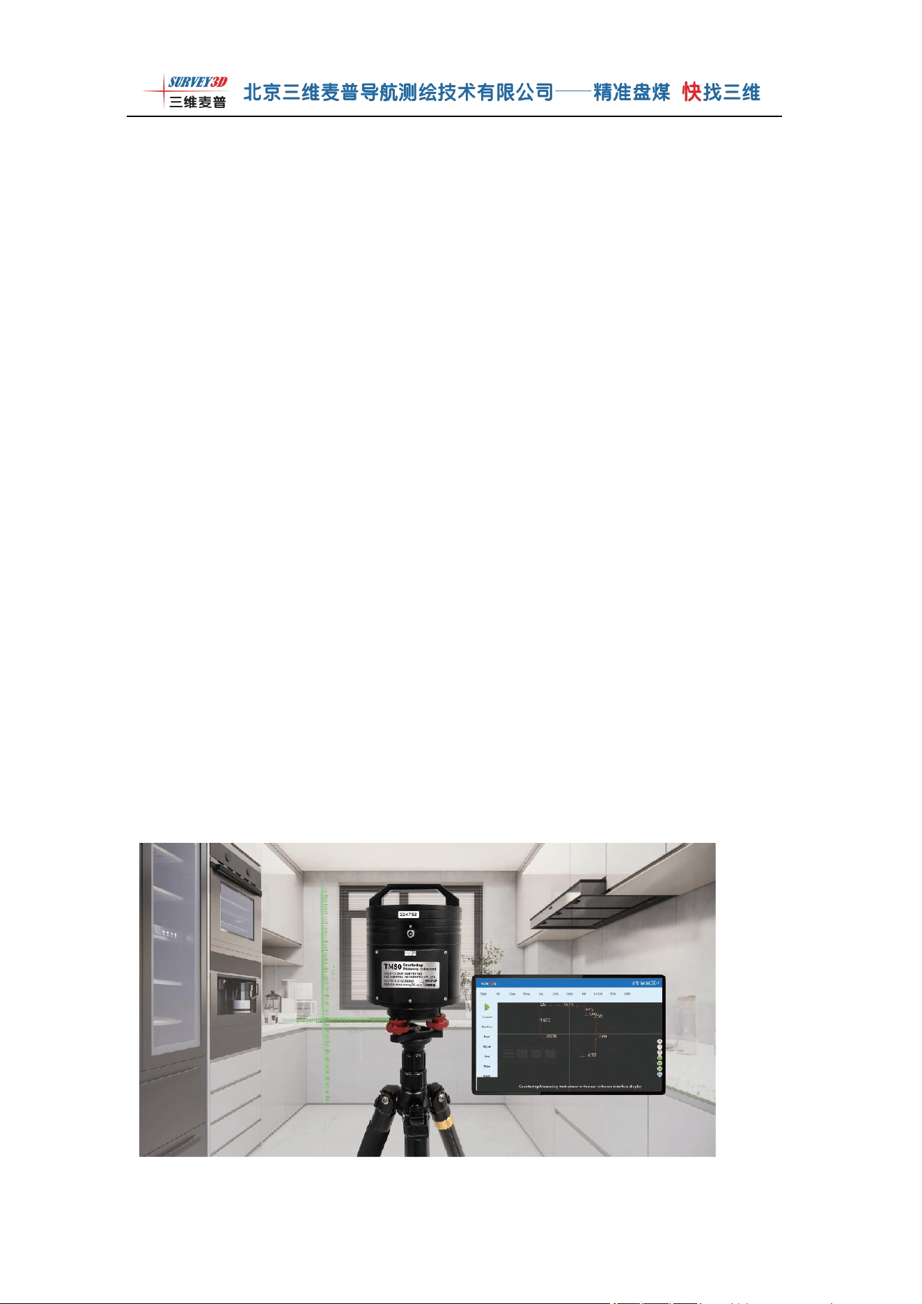
Older Countertop Measuring Instruments on the market have an angle
measurement accuracy of only 0.1° with significant errors, a measurement range of less
than 5 meters, and require manual dimension verification, otherwise the margin of error
is too large and prone to mistakes, making the process time-consuming and labor-
intensive.
Sanwei Maipu, a manufacturer with 18 years of experience in producing 3D laser
scanners, has leveraged its proprietary 3D laser scanner total station patent technology
to launch the TM80 Countertop Measuring Instrument, achieving an angle
measurement accuracy of up to 0.0005° (2 arc seconds).
With a measurement range exceeding 80 meters, eye-safe millimeter-level ranging
laser, and on-site CAD drawing export, it provides users in the stone countertop cutting
industry with a broader, more precise, and reliable measurement solution.
In the custom cabinetry, wooden door customization, carpet installation, and
building surveying industries, as well as in tunnel monitoring and oil tank inspection
fields, it can measure door frame building CAD outline shapes, cabinet installation
shapes,
irregular countertop dimensions, and stair profiles. The TM80 2D Countertop
Measuring Instrument can be widely applied.
第 5 页 共 57 页
1 Instrument Checklist
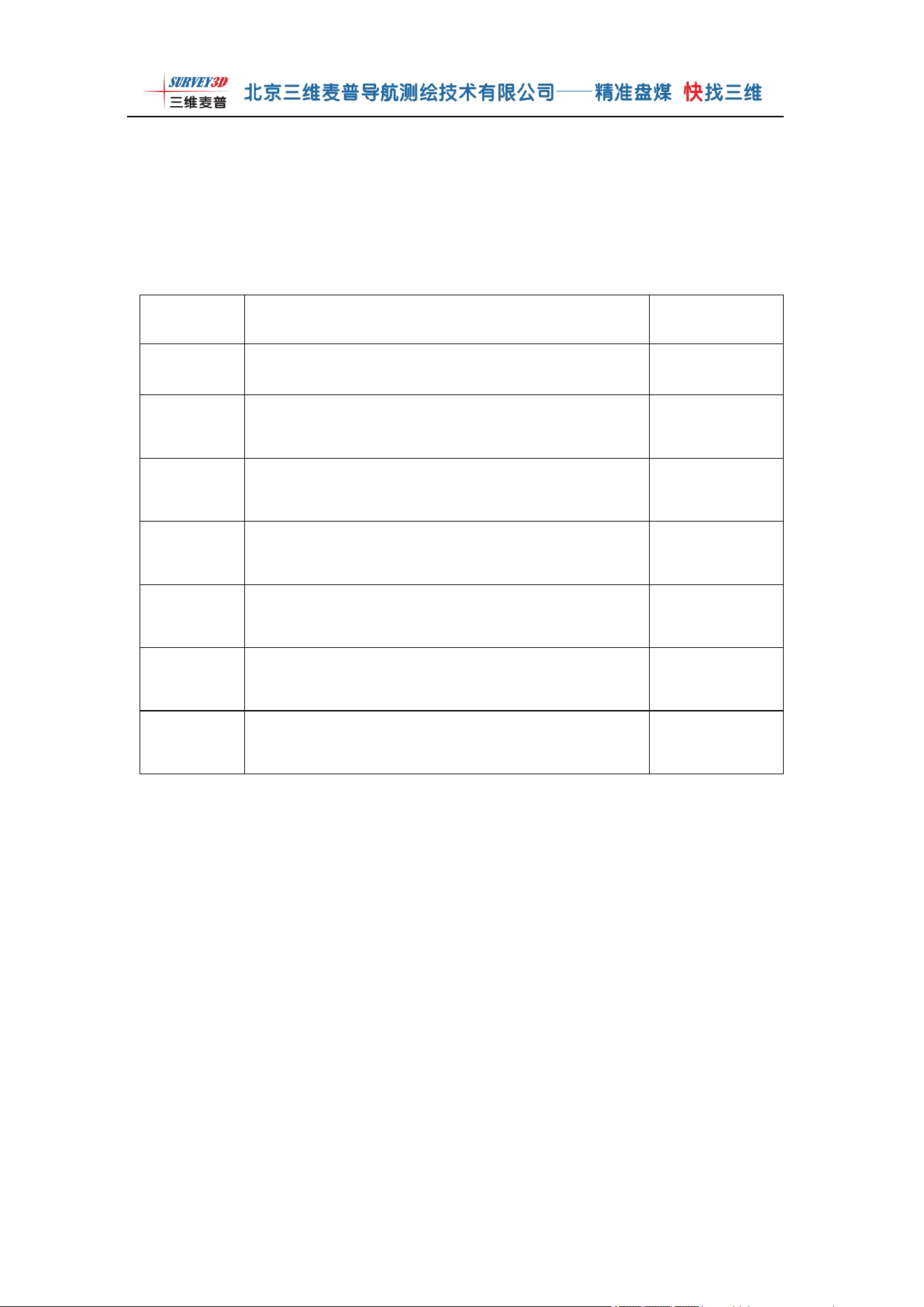
After receiving the instrument, please read the product user manual carefully. The
instrument should include the following items:
No.
Product Name
Quantity
1
Countertop Main Unit
1 unit
2
Tripod
1 set
3
Three-Jaw Base
1 piece
4
User Manual
1 copy
5
Certificate of Conformity
1 piece
6
Warranty Card
1 piece
7
Software USB Drive
1 piece
第 6 页 共 57 页
2 Specifications
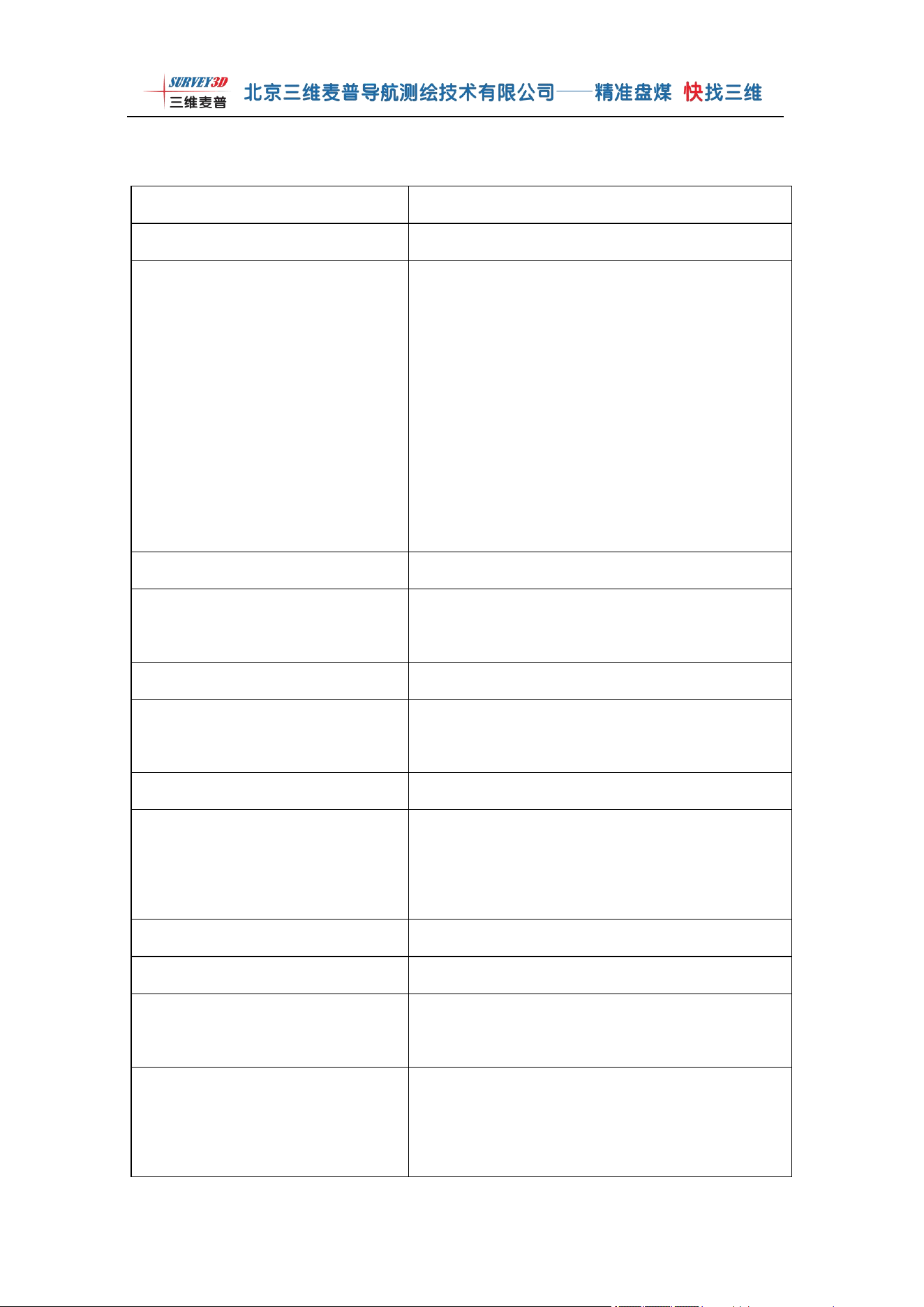
Laser Measuring Range
0.05-80m
Angle Measurement Accuracy
0.0005° (2″)
Distance Measurement Accuracy
±1mm (<10m), ±1.5mm (<20m), ±1.7mm
(<30m)
±1.9mm (40m), ±2.1mm (50m), ±2.3mm
(<60m), ±2.8mm (<80m)
±
1mm (<10m),
±
1.5mm (<20m),
±
1.7mm
(<30m)
±
1.9mm (40m),
±
2.1mm (50m),
±
2.3mm
(<60m),
±
2.8mm (<80m)
IP Rating
IP65
Measurement Range
Manual or automatic rotation, 360°
omnidirectional scanning
Battery Type
11.1V built-in 3500mAh lithium battery
Drive Mode
Friction brake technology, motor drive or
manual drive available without accuracy loss
Instrument Weight
2.6kg
Product Dimensions
With handle: Diameter 12.7cm × Height 21cm,
Without handle: Diameter 12.7cm × Height
17.1cm
Operating Temperature
-40~60°C
Data Transmission
Bluetooth
Cross Line
High-precision green laser cross line, switchable
at any time, anti-glare
Ranging Laser
Class 2 eye-safe red ranging laser, 635 nm
wavelength, < 1 mW; Class 2 green cross line
laser, 520 nm wavelength
第 7 页 共 57 页
Leveling Method
Three-jaw base, fast and precise leveling via
three leveling screws
Mounting Method
Supports upright, inverted and horizontal
mounting
Data Format
*.dxf (CAD file), *.csv (Excel point cloud file),
*.db (Factory original file)
Point Cloud Registration
Supports station setup and orientation survey,
resection, and automatic registration of multi-
station point cloud data on the instrument
Device Connection
Machining center, 4-axis & 5-axis bridge saw,
waterjet, strip cutting machine, etc.
Display Hardware
Display on Android phones or tablets, supports
HarmonyOS for mobile devices
Notes: ① When reflectivity is greater than 70% and ambient light is less than 3000
Lux, the measurement range exceeds 80 meters. ② Distance measurement accuracy
within 10 meters is ±1mm.

第 8 页 共 57 页
Chapter 2 Tabletop Measurement Software
Description
When first downloading the measurement software, make sure to enable all
permissions in the software interface (if permissions are not enabled, the software
will not function).
After the software installation is complete, restart the tablet or phone.
The tabletop instrument program does not distinguish between 32-bit and 64-bit
systems; it is a universal cross-platform operating system program.
Please modify the ranging difference value in the software to the correct number.
Bluetooth connection and operation must be initiated from within the graphic
interface only; do not use external buttons to start operations.
Before each measurement, you need to reopen the program to perform the
measurement.
Ensure that both the phone and the instrument have sufficient battery charge.
The green light on the back of the instrument cycles every 5 seconds. When the
green light is on for 1 second and off for 4 seconds, it indicates the instrument is in a
low-battery state.
After turning off the instrument, please wait 30 seconds before turning it on again.
Otherwise, measurement data may fail to return, resulting in no data.
Before use, ensure that the circular level bubble is centered in all directions (it
should be within the inner circle).
To avoid the instrument laser producing an elliptical light spot on the wall, try to
position the instrument at a 45° angle to the wall being measured.
If measuring countertop sections beyond 20 meters, please change the maximum
distance setting in the station setup configuration to the actual distance from the
measuring instrument to the countertop.
第 9 页 共 57 页
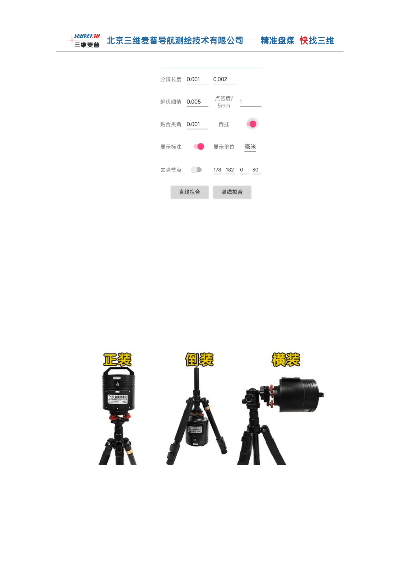
Standard parameter properties are shown in the figure. If the measurement length
is too long and causes the fitted line segment to not fit properly, you can adjust the
起
伏
threshold appropriately so that the fitted line segment overlaps with the white point
cloud.
Note: The device supports flexible installation methods, including upright,
inverted, and horizontal mounting, adaptable to on-site conditions. The instrument main
unit is equipped with level bubbles on both the top and bottom for quick calibration and
leveling.
第 10 页 共 57 页
Chapter 3 Operating Procedure
1
、
Unboxing and Assembly
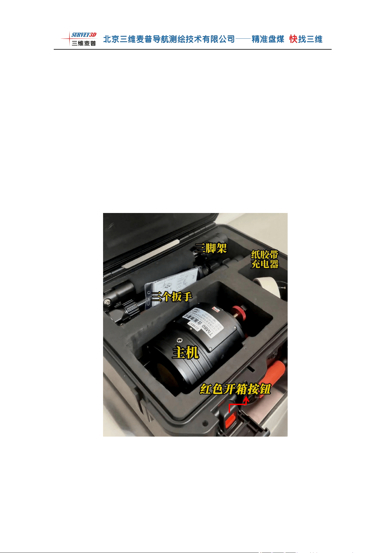
Press the red button on the instrument case to open the lid. The case contains a
tripod, measuring instrument main unit, masking tape, charger, and three wrenches of
different sizes. See Figure 1-1.
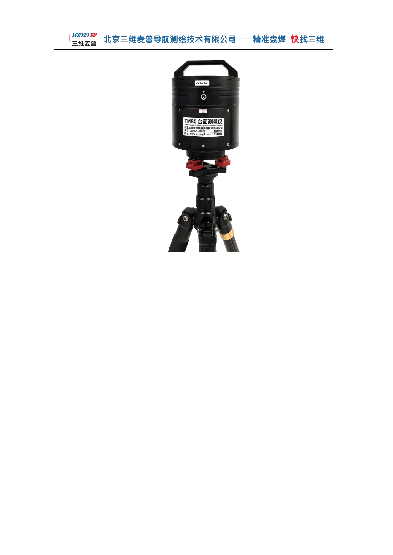
Remove the tripod and extend it; the leg height can be adjusted according to on-
site requirements. Then remove the main unit, align the screw port at the bottom of
the main unit base with the tripod screw interface, and rotate to tighten. The main unit
and tripod are now assembled. See Figure 1-2.
Figure 1-1
第 11 页 共 57 页
Figure 1-2
2 Connection
Please confirm that the bubble level on the TM80 main unit is centered, ensuring
the instrument is placed stably. Press the red power button on the main unit to start the
instrument. Press the green laser power button to activate the green laser, achieving
coaxial red-green laser alignment, which effectively improves countertop measurement
accuracy. See Figure 1-3.
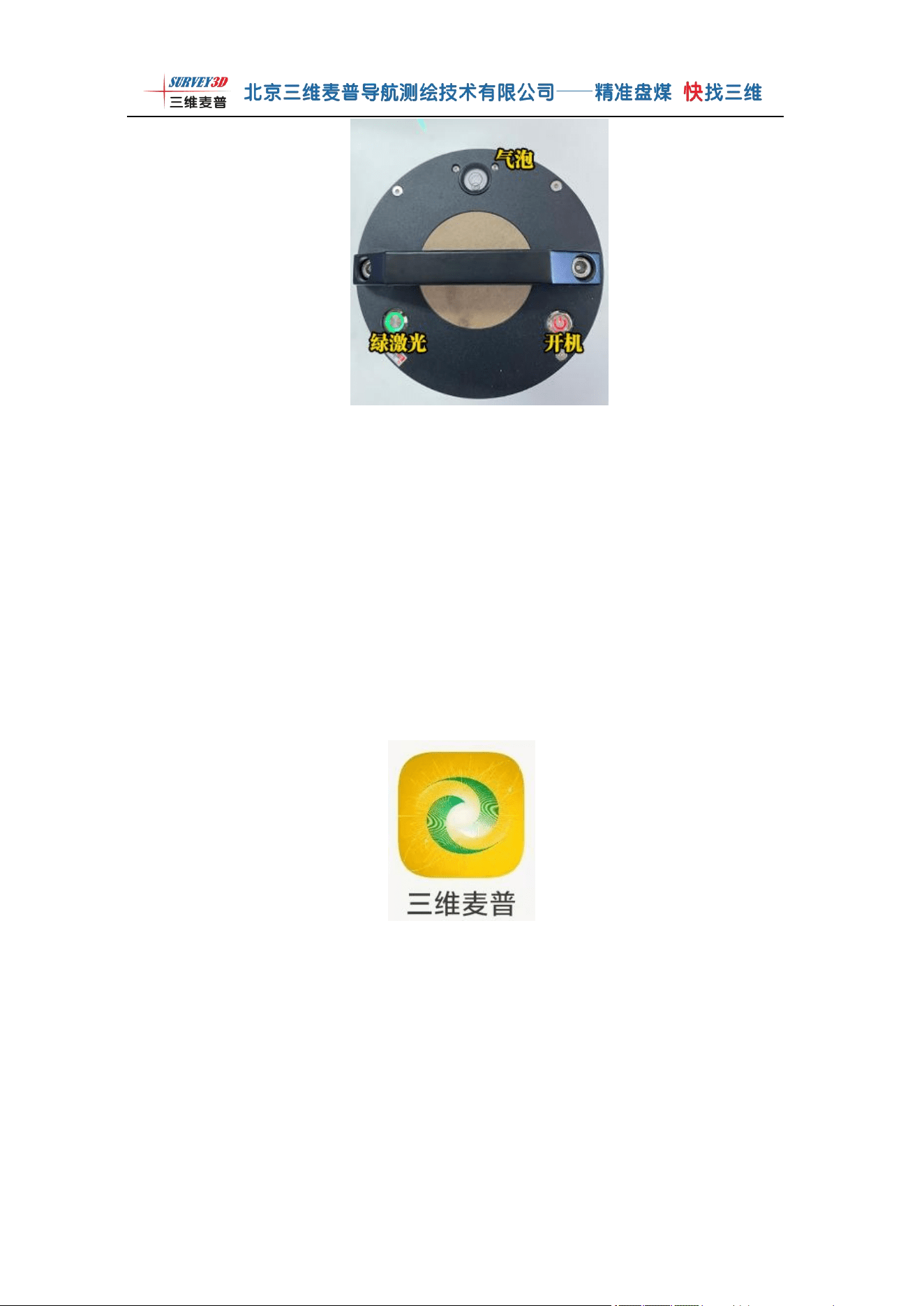
第 12 页 共 57 页
Figure 1-3
Open the Sanwei Maipu APP (see Figure 1-4), enter the main interface, and
select [Connect] in the upper left corner (see Figure 1-5). Align the red laser
perpendicular to the wall before connecting Bluetooth. Connect to the [sanwei]
Bluetooth signal (see Figure 1-6). When connecting Bluetooth, it will also prompt you
to aim the red light at the front wall, then click Next (see Figure 1-7). After the
software connection is complete, it will automatically return to the main interface.
Once connected, the Connect button will switch to [Disconnect] status, and the
instrument will enter measurement-ready mode. (See Figure 1-8)
Sanwei Maipu APP (Figure 1-4)
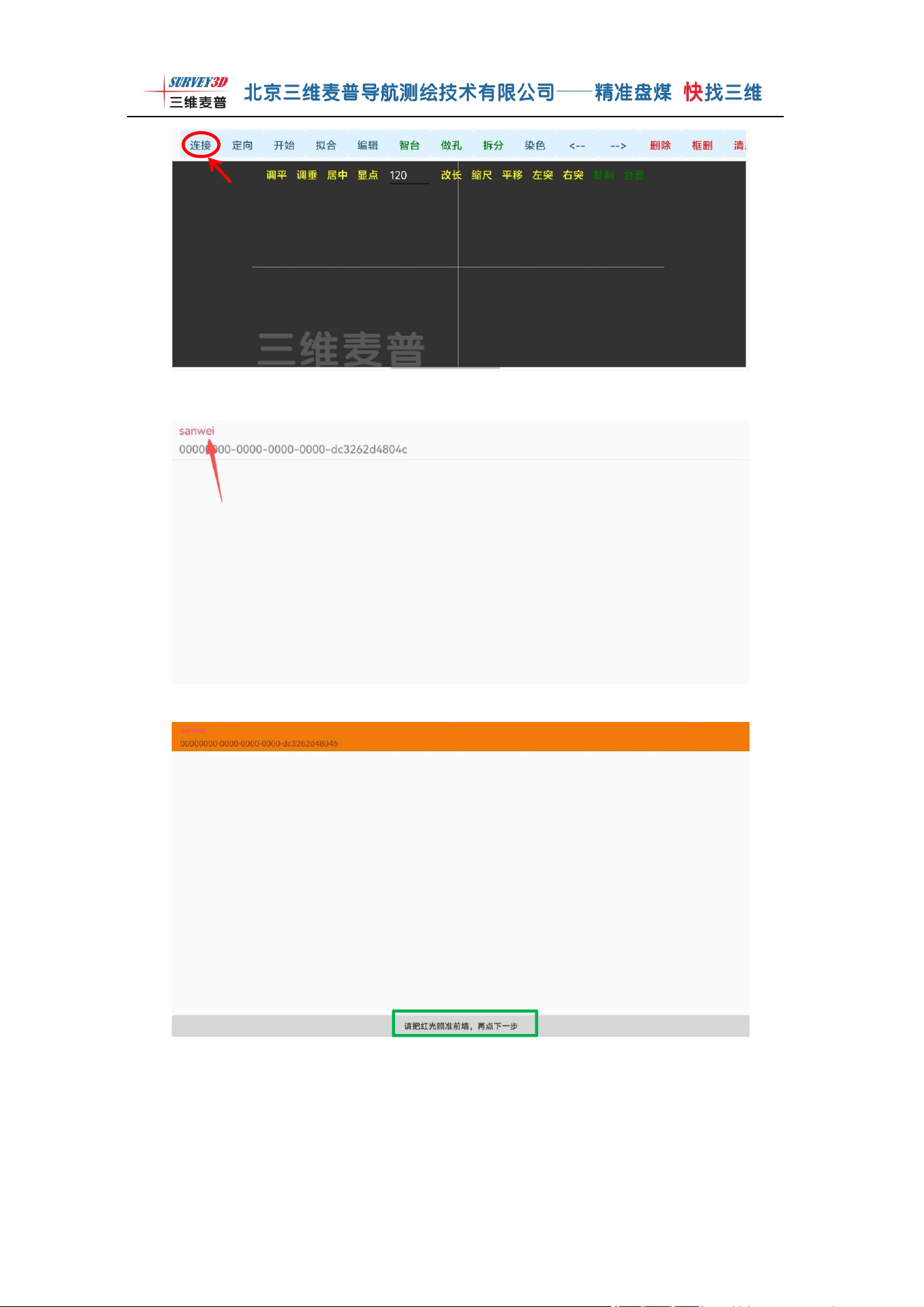
第 13 页 共 57 页
Countertop Measuring Instrument Main Interface Figure 1-5
Figure 1-6
Figure 1-7
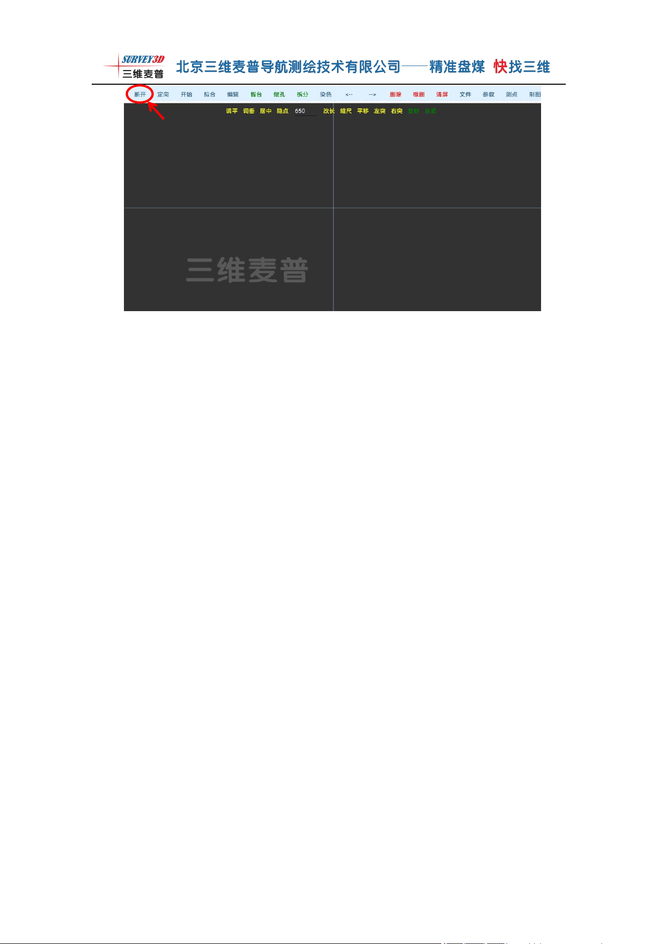
第 14 页 共 57 页
Figure 1-8
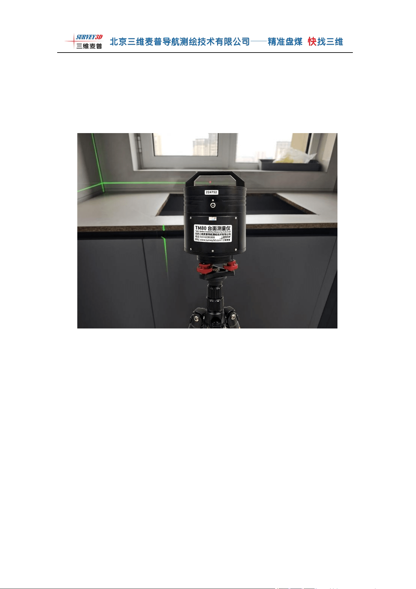
第 15 页 共 57 页
2 Prepare for Measurement
First, rotate the red laser to the starting measurement point to prepare for
measurement. See the figure below.
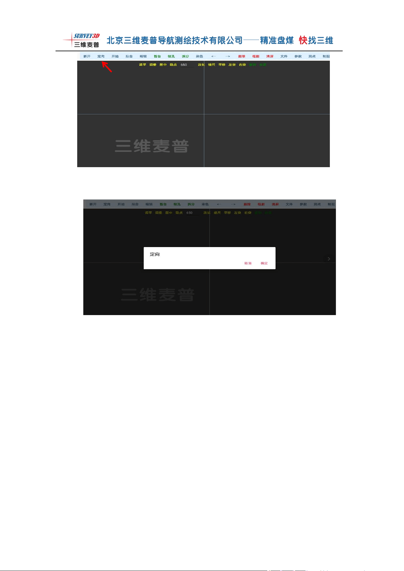
3 Start Measurement
Click the [Start] button on the main interface to enter the orientation calibration
step. At this point, confirm again whether the red laser is perpendicular to the front
wall. If not perpendicular, please adjust it to a perpendicular state. After orientation
calibration is complete, click [OK] in the orientation popup. See Figures 1-9 and 1-10.
第 16 页 共 57 页
Figure 1-9
Figure 1-10
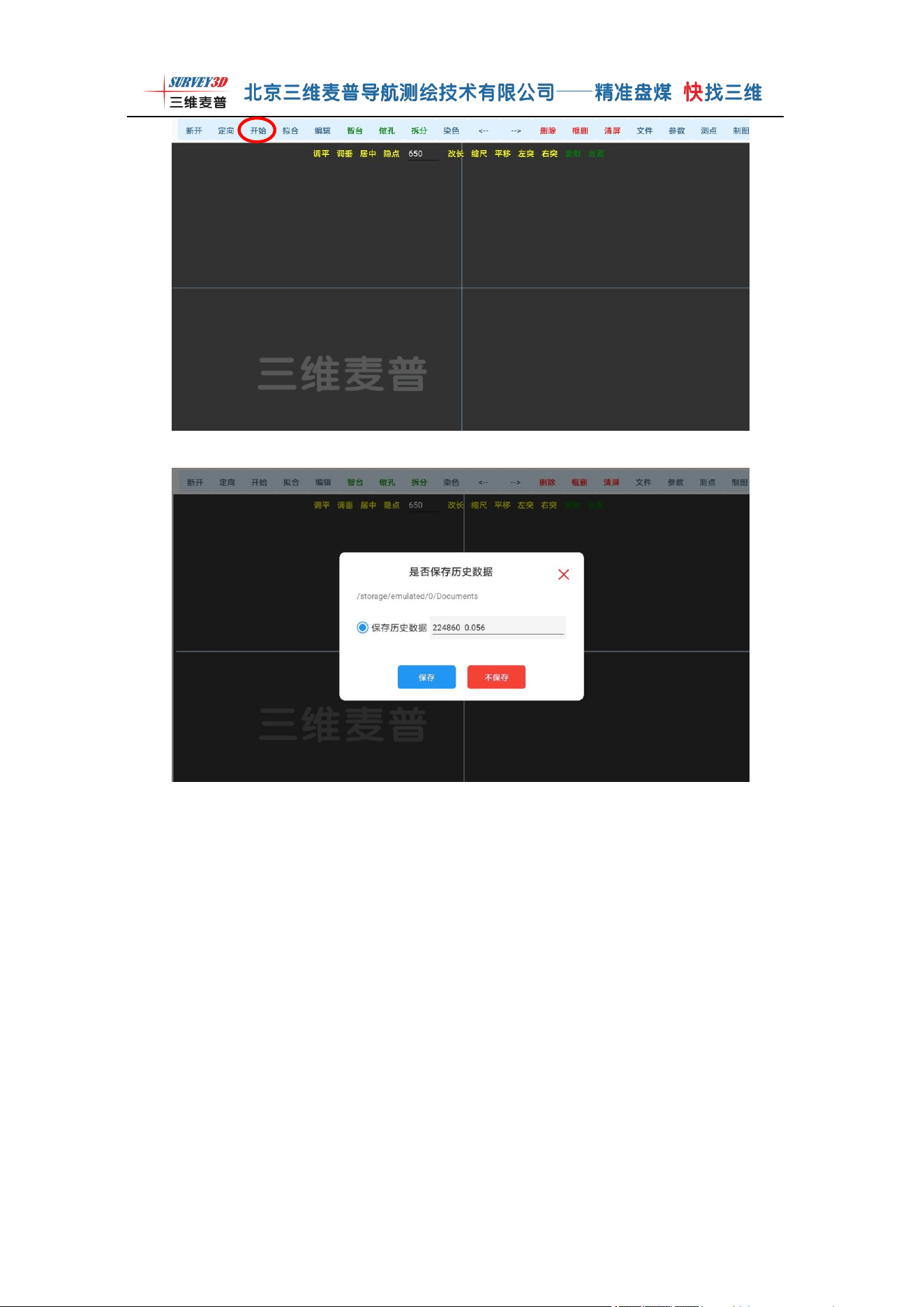
After orientation confirmation is complete, return to the main interface and click
the [Start] button. The page will display a prompt asking [Save History Data?]. You
can choose [Save] or [Don't Save] as needed. After confirmation, it will automatically
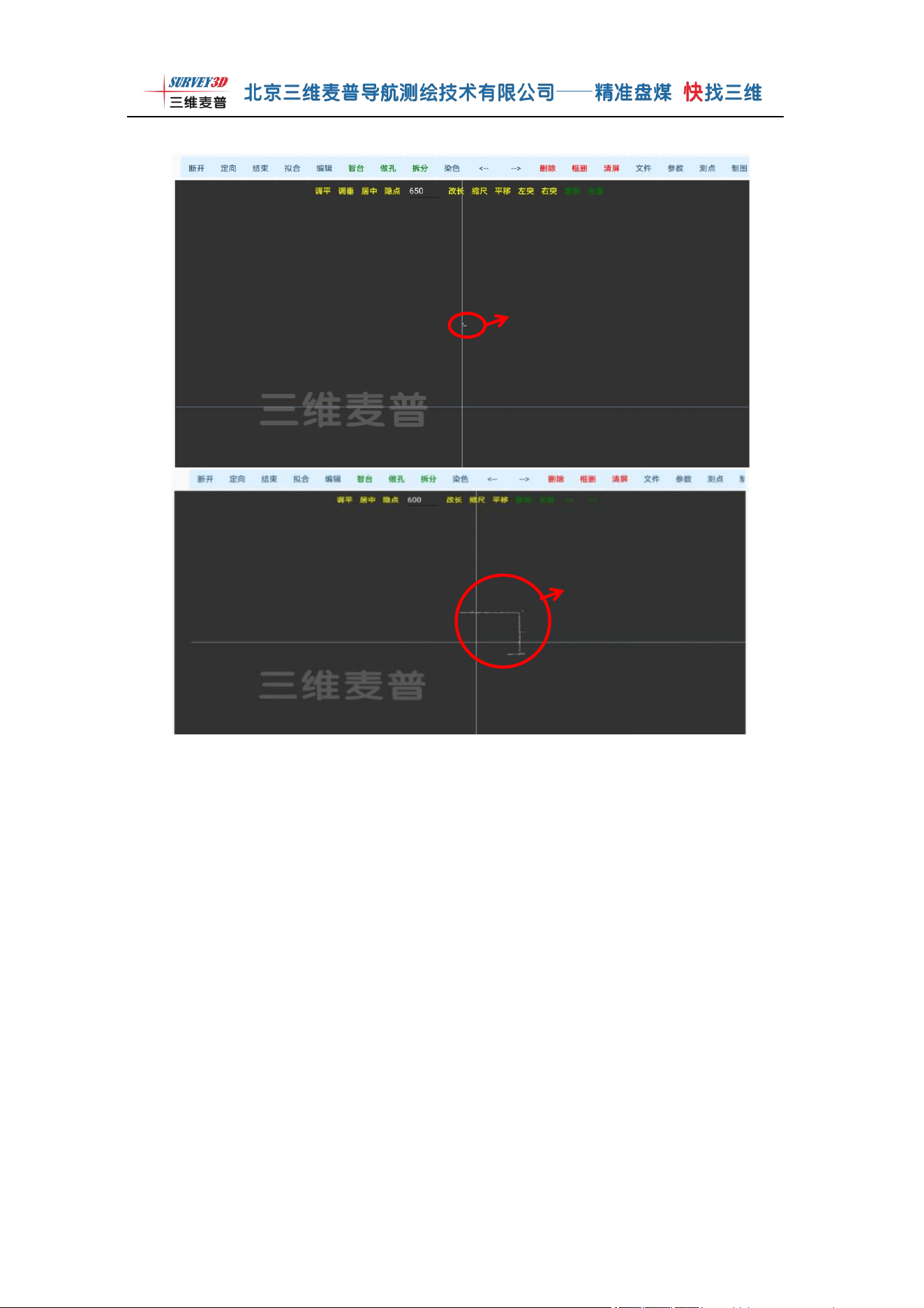
return to the main interface, and the device will start scanning and display point cloud
data, showing the point cloud map in real time. See Figures 1-11, 1-12, and 1-13.
第 17 页 共 57 页
Figure 1-11
Figure 1-12
第 18 页 共 57 页
Figure 1-13
点云数据
点云数据
第 19 页 共 57 页
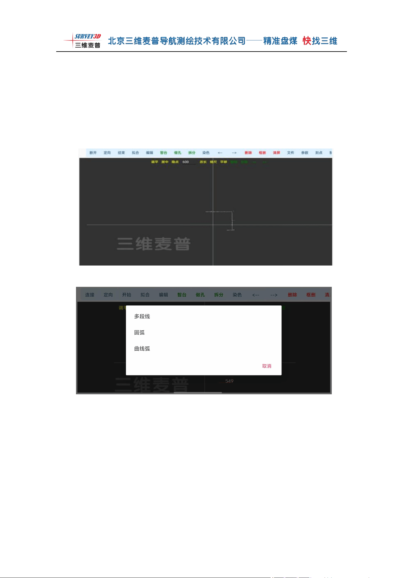
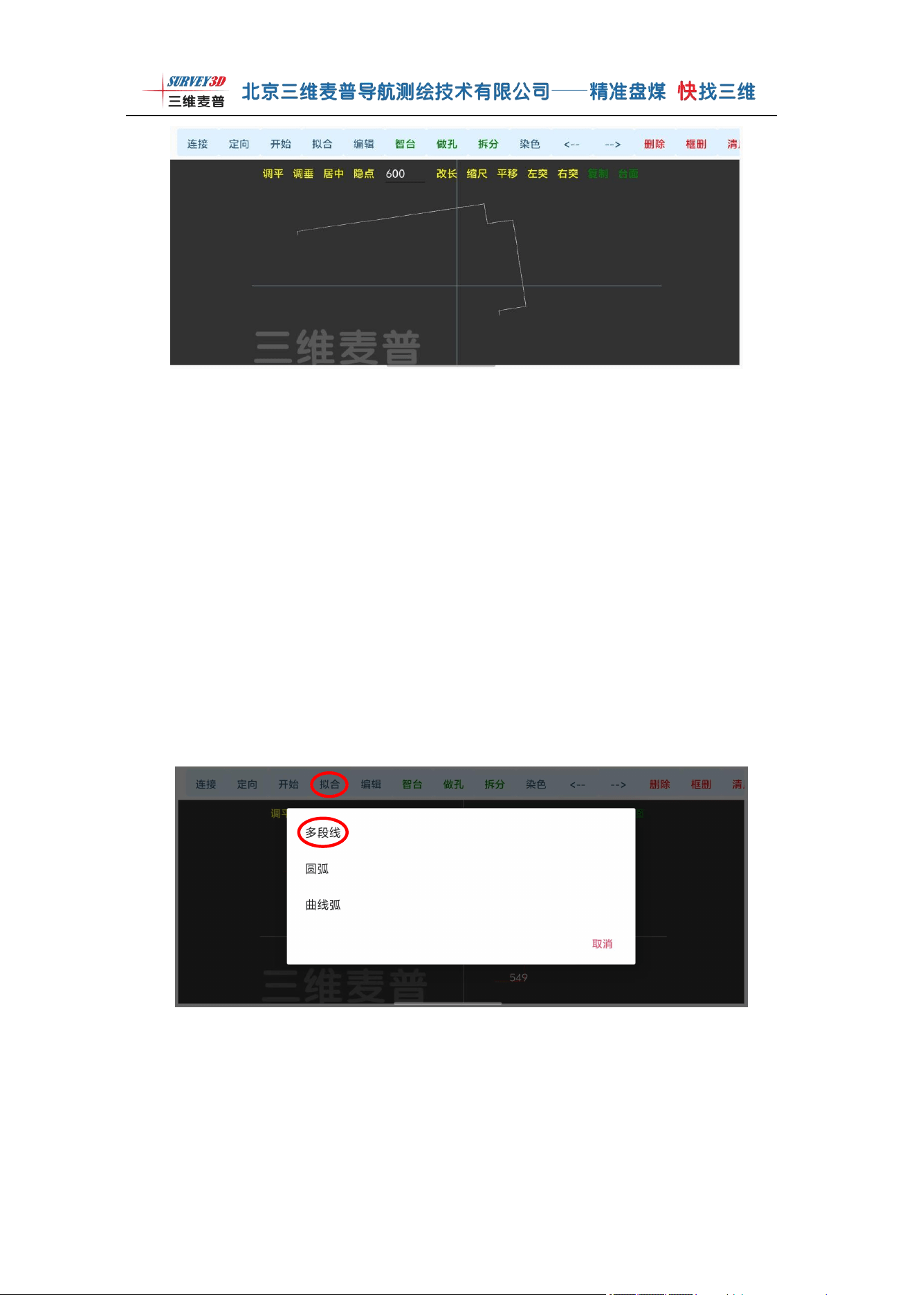
When the red laser moves to the end point, click the [End] button, and the
measuring instrument will stop immediately. After measurement is complete, a popup
will appear with options for polyline, circle, and curve arc. You can select the
appropriate type as needed. The countertop measured this time has a polyline
structure. After returning, the main interface will automatically display the measured
point cloud polyline graphic. See Figures 1-14, 1-15, and 1-16.
Figure 1-14
Figure 1-15
第 20 页 共 57 页
Figure 1-16
4 Function Introduction:
Based on the completed measurement and generated point cloud polyline
graphic, proceed with the following function operations:
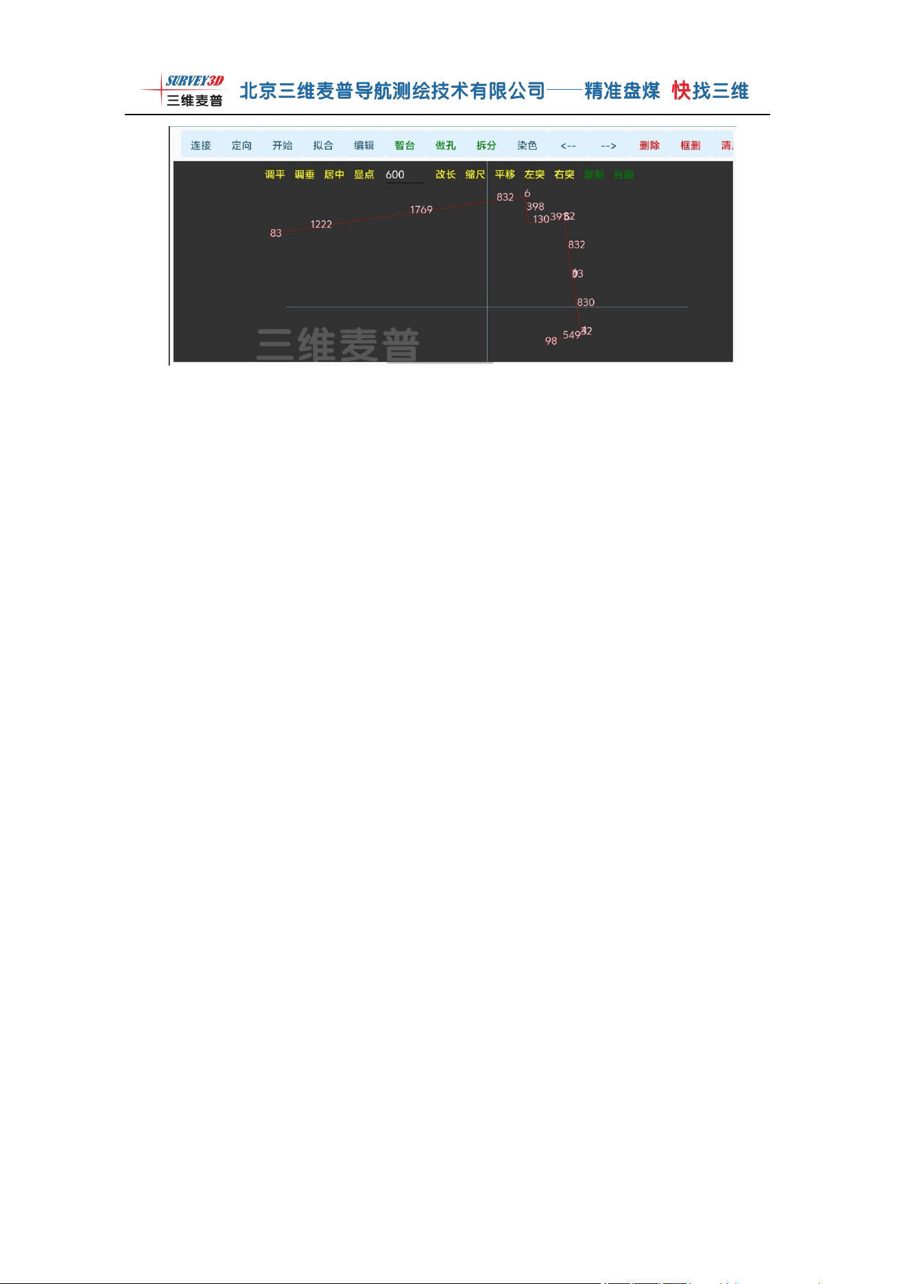
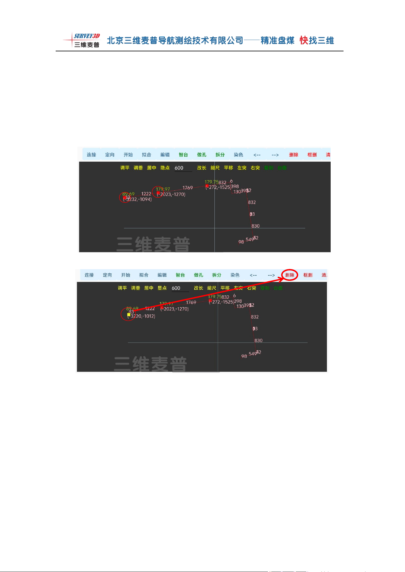
Click the [Fit] button, and the interface will display a selection window for
polyline, circle, and curve arc. You can choose according to the actual on-site
conditions. The countertop measured this time has a polyline structure, so select
polyline directly, and the software will automatically complete the graphic fitting. See
Figures 1-17 and 1-18.
Figure 1-17
第 21 页 共 57 页
Figure 1-18
第 22 页 共 57 页
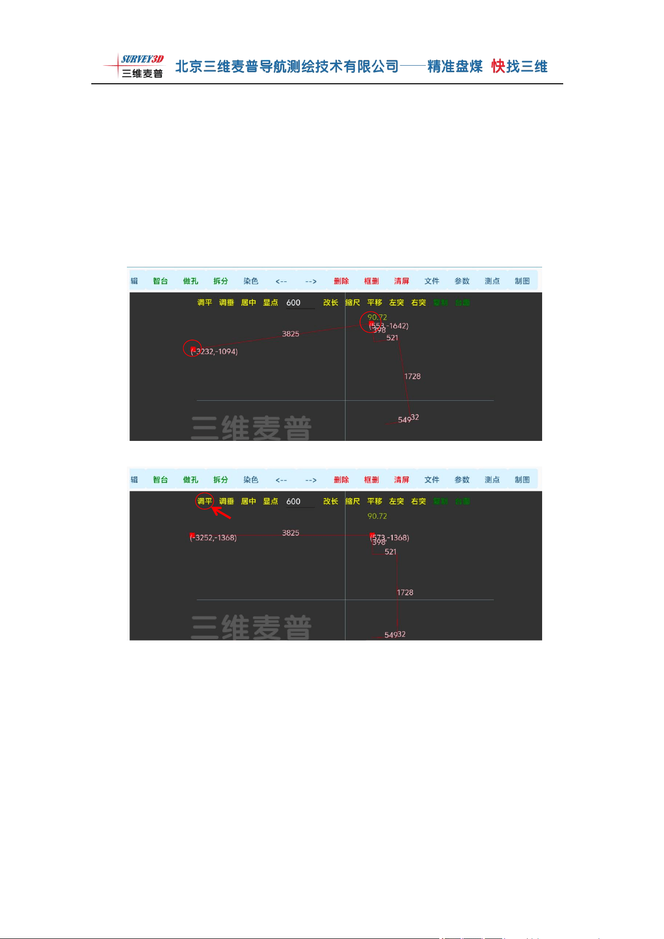
After fitting is complete, excess noise points will appear in the point cloud data
and need to be cleaned up. First, click on the point cloud image, and red control points
will appear on the line segments. Select the red endpoint to be deleted, and when the
endpoint turns yellow, click [Delete] to complete the single noise point deletion.
Follow the same procedure to select and delete other excess endpoints one by one
until all noise points are cleaned up. See Figures 1-19 and 1-20.
Figure 1-19
Figure 1-20
第 23 页 共 57 页
After all noise points are cleaned up, each line segment should retain only one
annotation, and then you can begin the [Level] operation.
Leveling operation instructions: First select the line segment to be leveled. After
selection, red endpoints will appear at both ends of the line segment (see Figure 1-21),
then click the Level button on the interface to complete the leveling.
For example, select line segment number 3823. After both endpoints turn red,
click the [Level] button to level the line segment with one click (see Figure 1-22).
Figure 1-21
Figure 1-22
After all noise points are cleaned up, each contour line segment should retain
only one annotation, and then you can proceed with the [Plumb] operation.
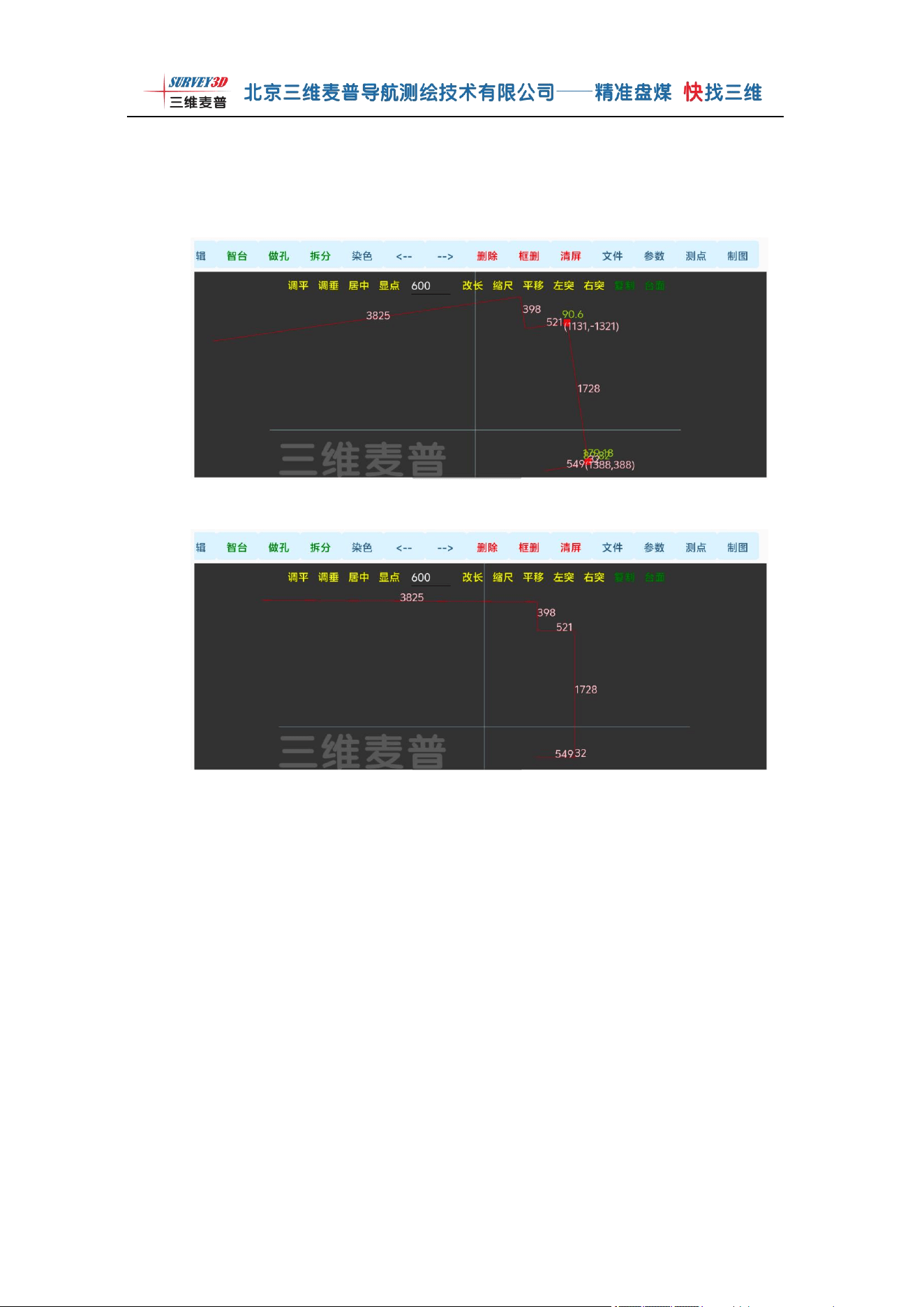
Plumb operation notes: First select the line segment to be plumb-adjusted. After
selection, red endpoints will appear at both ends (see Figure 1-23), then click the
Plumb button on the interface to complete the vertical correction with one click.
第 24 页 共 57 页
Example: Select line segment number 1728. After both endpoints turn red, click
the [Plumb] button to quickly complete the vertical correction of the line segment.
(See Figure 1-24)
Figure 1-23
Figure 1-24
第 25 页 共 57 页
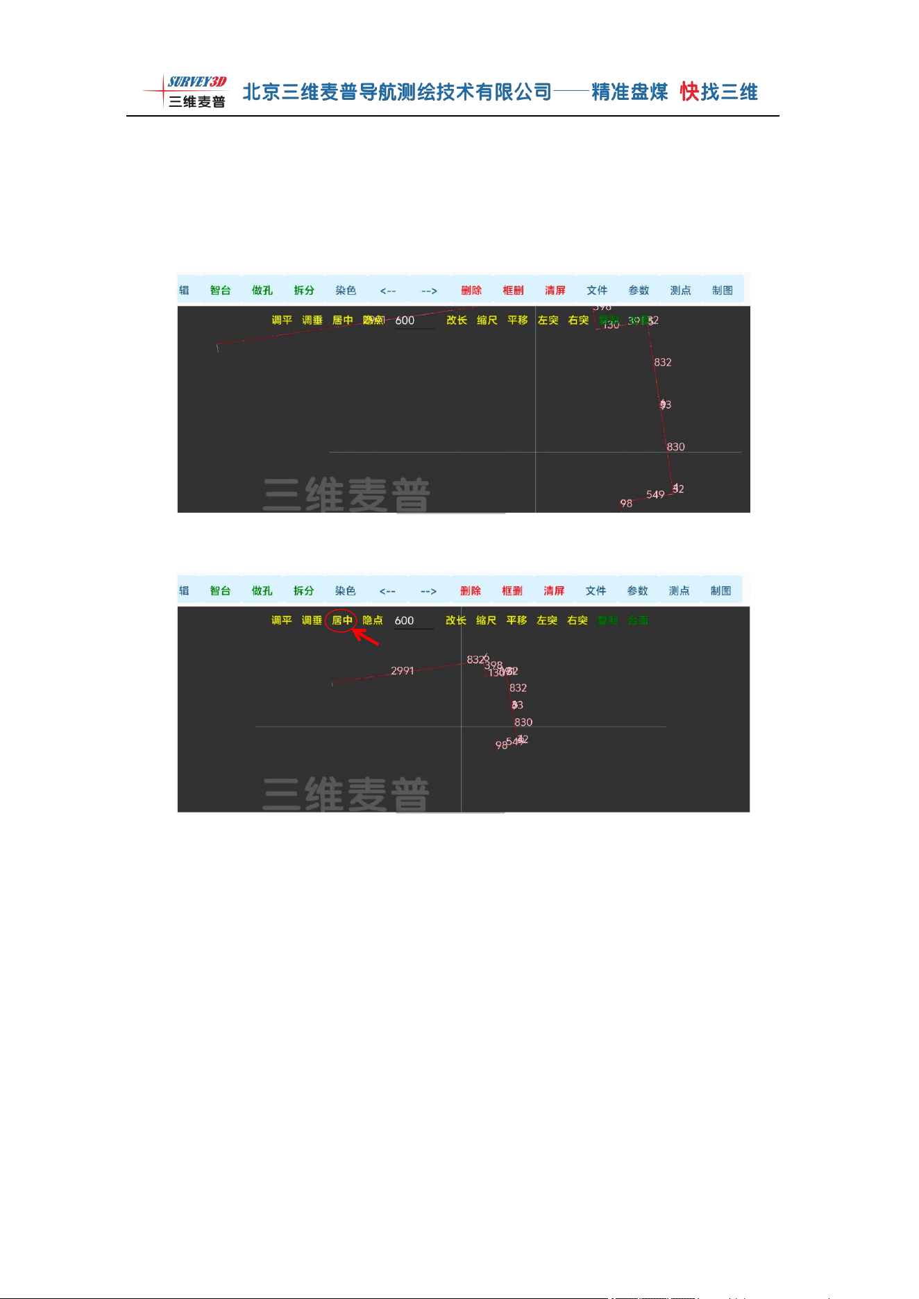
Center: If you cannot find the graphic position in the point cloud view after
performing point deletion, zooming in or out (see Figure 1-25), click [Center] to
automatically reset the point cloud view to the center of the interface. (See Figure
1-26)
Figure 1-25 Point cloud zoomed view not found
Figure 1-26 Point cloud centered back to interface center position
第 26 页 共 57 页
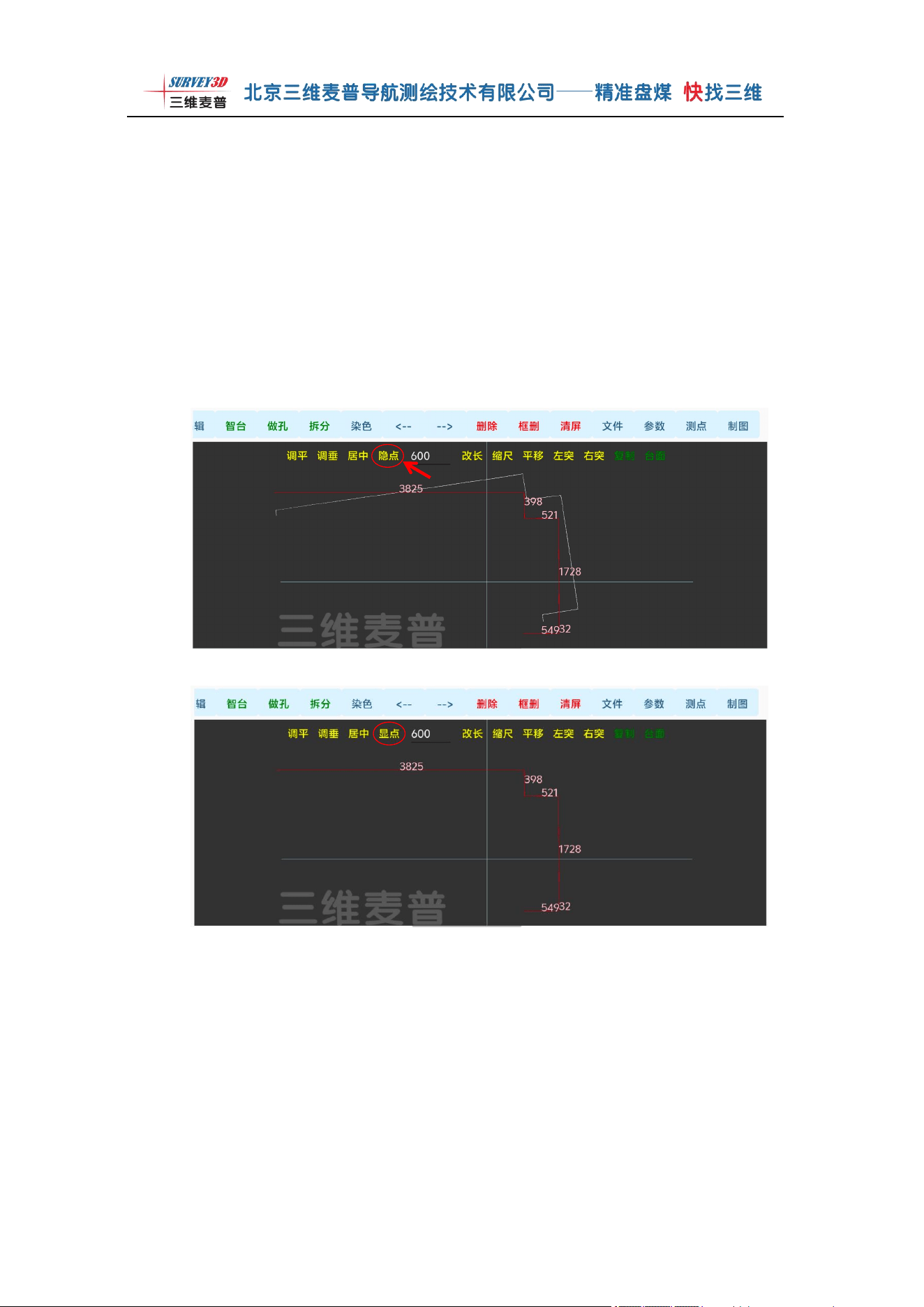
Hide Points (Show Points): After measurement is complete, the interface
automatically generates a white point cloud graphic. After fitting, red contour line
segments are generated. If the white point cloud is no longer needed after fitting
and noise point deletion, or if the white point cloud visually conflicts with the red
contour lines during subsequent leveling operations, click the [Hide Points] button
to hide the white point cloud. After hiding, the button automatically switches to
[Show Points]. You can toggle between hiding/showing the point cloud at any time
according to your needs. See Figures 1-27/1-28.
Figure 1-27 Both white point cloud and red contour lines are present
Figure 1-28 White point cloud hidden
第 27 页 共 57 页
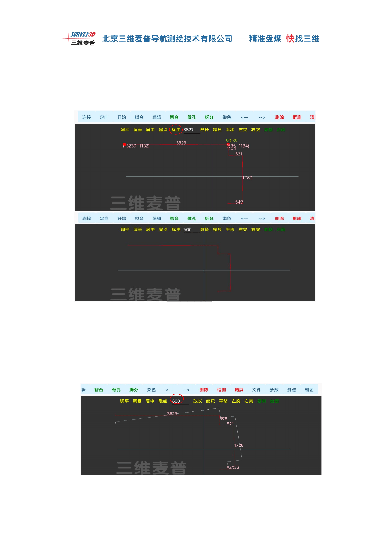
Annotation: The annotation function displays length values on each line
segment. Click the [Annotation] button to hide all line segment values with one
click, flexibly turning off annotation display as needed. Click the annotation
button again to display all line segment length values again. See Figure 1-29.
Figure 1-29
600 Value Box: The default value is 600. This input box applies globally to the
functions on the right: Extend, Shrink, Offset, Left Protrusion, and Right
Protrusion. When operating, first select the line segment to be adjusted, then enter
the corresponding value in the 600 value box to quickly achieve line segment
extension, shrinkage, offset, left protrusion, right protrusion, and other effects.
See Figure 1-30.
See Figure 1-30
第 28 页 共 57 页
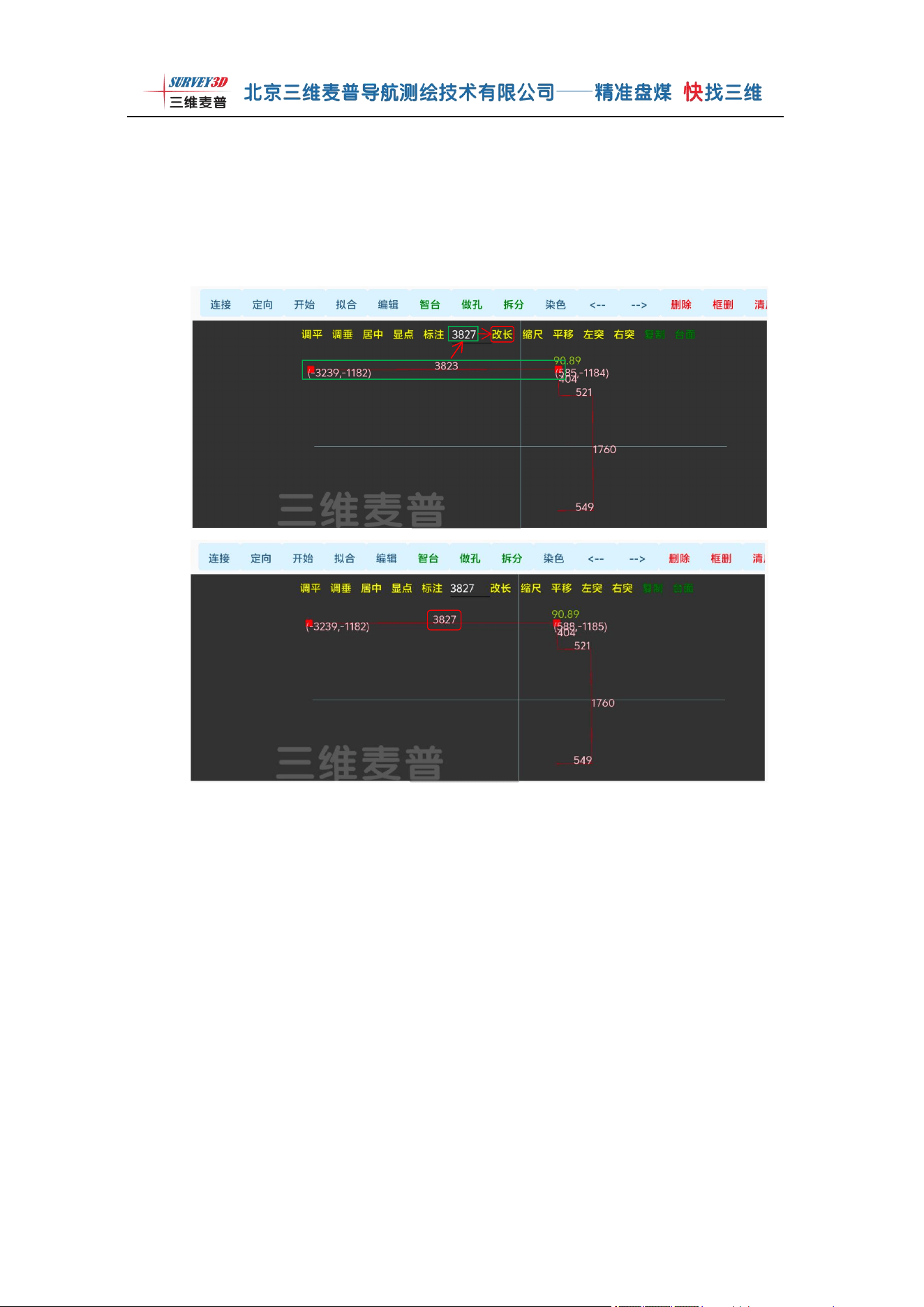
Extend: Select any line segment, and both endpoints will turn red to indicate
selection. Change the default value of 600 in the value input box to the total length of
the line segment after adjustment, then click [Extend] to complete the line segment
extension. Example: To extend line segment 3823 by 4mm, first select the line
segment so its endpoints turn red, change the value box to 3827, click [Extend], and
the line segment length will automatically update to 3827. The extension operation is
complete. See Figure 1-31.
Figure 1-30
第 29 页 共 57 页
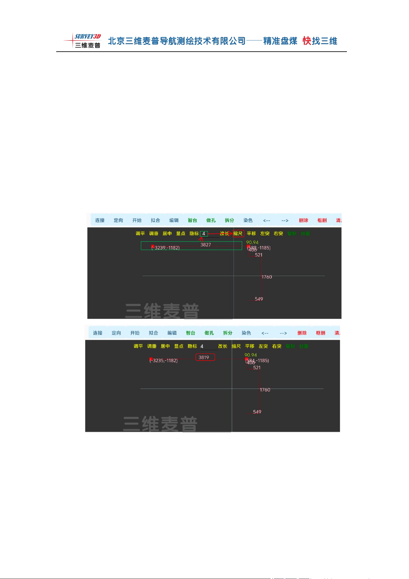
Shrink: Select any line segment, and both endpoints will turn red to indicate
selection. Change the default value of 600 in the value input box to the shrinkage
length, then click the [Shrink] button. Note: The left and right endpoints of the
line segment will each shrink inward by the value set in the input box,
automatically updating the total line segment length to complete the shrinkage
operation.
Example: To shrink line segment 3827 by 4mm on each side: First select the line
segment so its endpoints turn red, change the value box to 4, click [Shrink], and the
line segment length will automatically update to 3819. The shrinkage modification is
complete. See Figure 1-31.
Figure 1-31
第 30 页 共 57 页
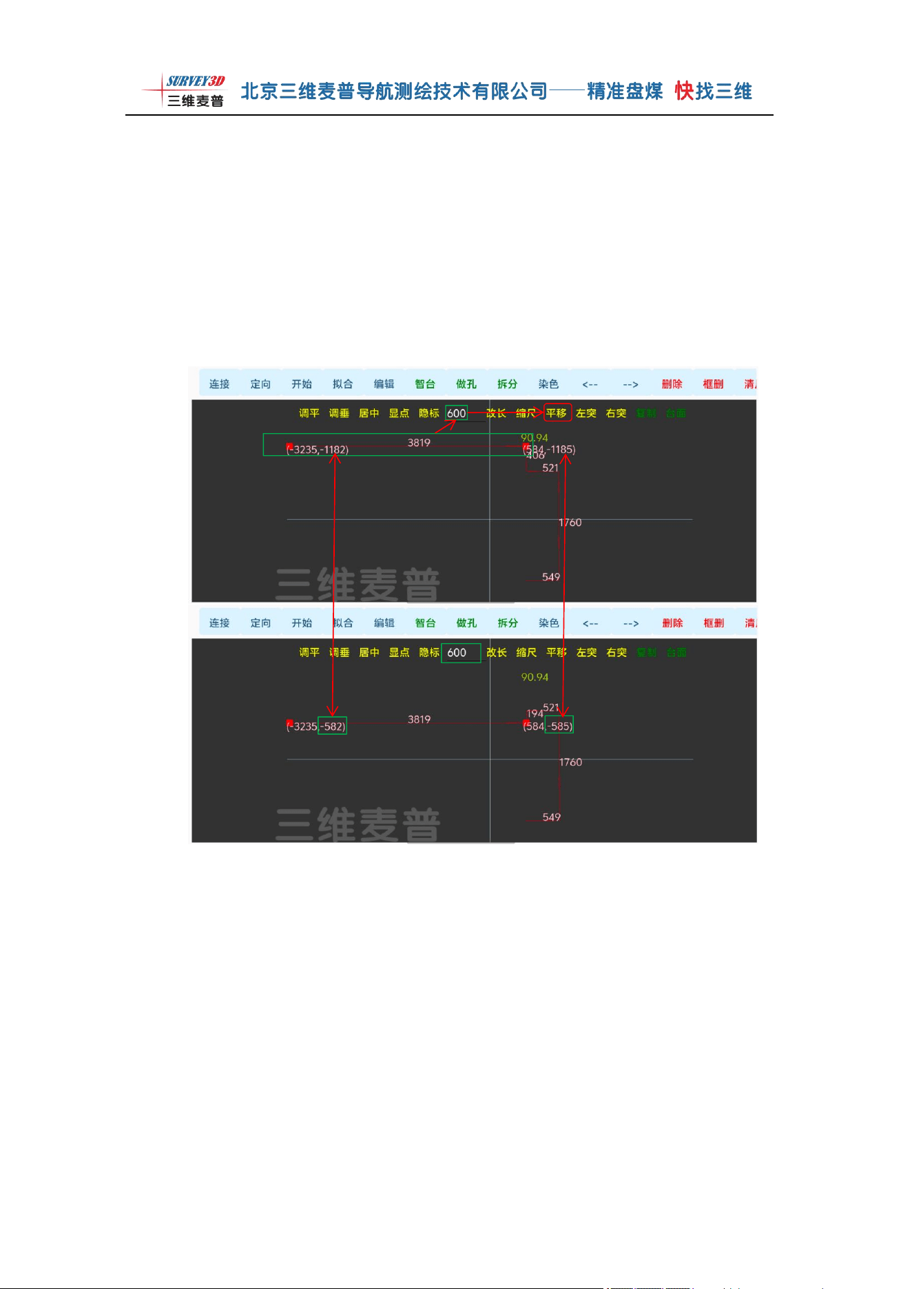
Offset: Select the line segment to be offset, change the default value of 600 in
the input box to the target offset distance, and click the [Offset] button to
complete the perpendicular offset at the specified value.
Example: For line segment 3819, if you need to offset downward by
600 perpendicularly, simply enter 600 in the input box and click the
[Offset] button to complete the 600 downward perpendicular offset.
See Figure 1-32.
Figure 1-32
第 31 页 共 57 页
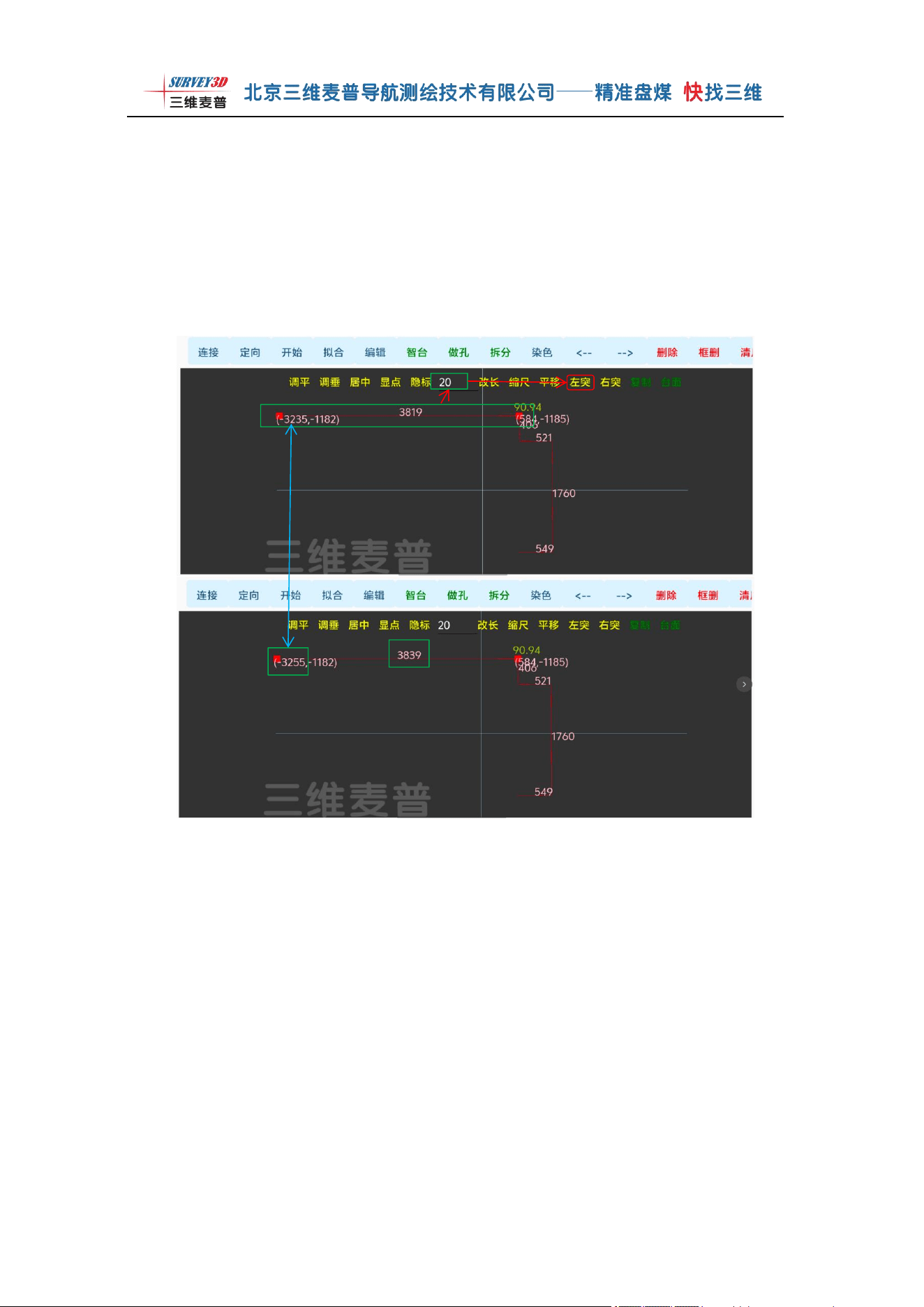
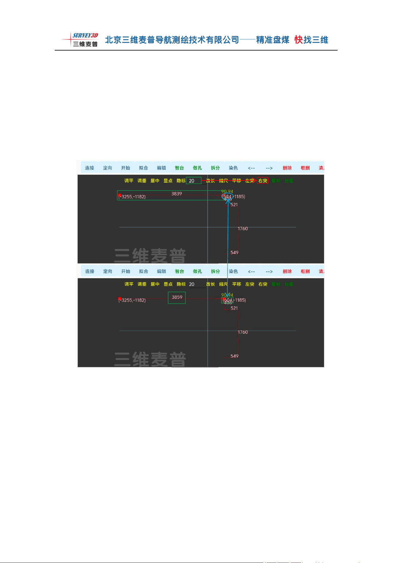
Left Protrusion: Select the line segment to be left-protruded,
and change the default value of 600 in the input box to the target
left protrusion distance. Example: Select line segment 3819. If you
need a left protrusion of 20, enter the value 20 and click the [Left
Protrusion] button to complete the left protrusion at the specified
distance, generating a line segment value of 3839. See Figure 1-33.
Figure 1-33
第 32 页 共 57 页
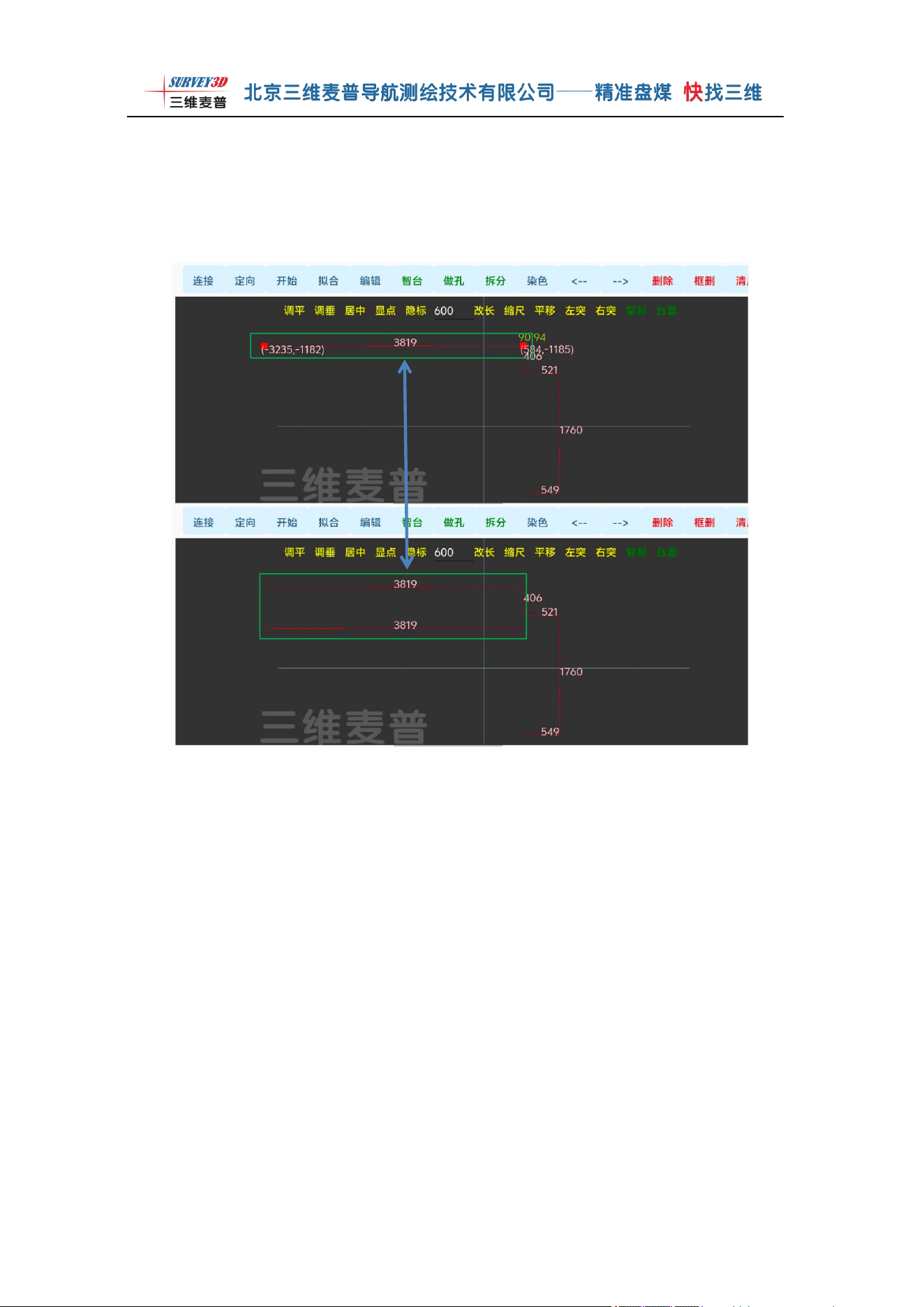
Right Protrusion: Select the line segment to be right-protruded,
and change the default value of 600 in the input box to the target
right protrusion distance. Example: Select line segment 3839. If you
need a right protrusion of 20, enter the value 20 and click the
[Right Protrusion] button to complete the right protrusion at the
specified distance, generating a line segment value of 3859. See
Figure 1-34.
Figure 1-34
第 33 页 共 57 页
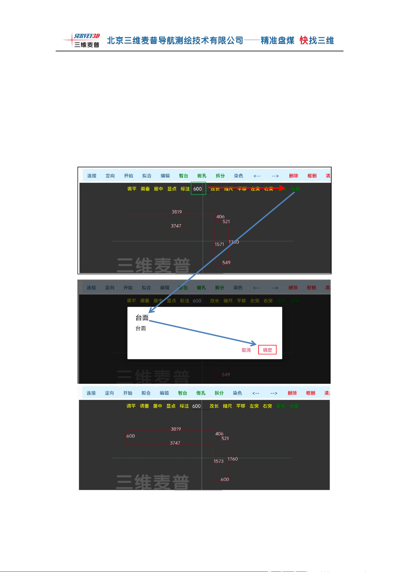
Copy: Select the line segment to be copied and click the [Copy] button to
copy the selected line segment. Example: Select line segment 3819, click the
[Copy] button, and a copy of the line segment with the same number 3819 will be
generated. See Figure 1-35.
Figure 1-35
第 34 页 共 57 页
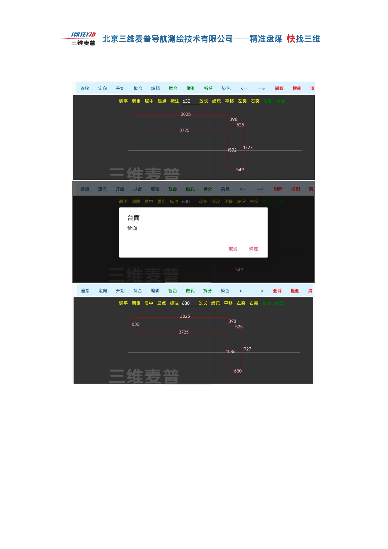
Countertop: After copying the line segment, change the default value of 600
in the input box to the desired countertop width value, click the [Countertop]
button, and click [OK] in the popup countertop dialog to generate the countertop
with the corresponding dimensions. Example 1: To generate a 600mm wide
countertop, change the default value in the input box to 600, click [Countertop],
click [OK] in the popup countertop dialog, and a 600-wide countertop will be
generated. See Figure 1-36.
Figure 1-36
第 35 页 共 57 页
Example 2: To generate a 630mm wide countertop, change the default value in the input
box to 630, click [Countertop], click [OK] in the popup countertop dialog, and a 630-
wide countertop will be generated. See Figure 1-37.
Figure 1-37
第 36 页 共 57 页
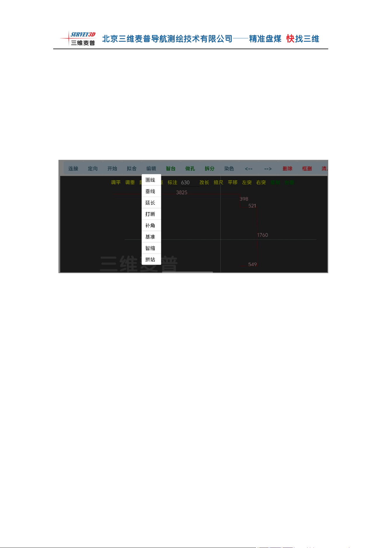
Edit: First use the online editing function to adjust line lengths and calibrate
dimensions accurately, and complete manual shrinkage before generating the
countertop. Once the countertop is generated, you can no longer perform shrinkage or
modify line lengths. Open the Edit dropdown menu, select the Draw Line function to
manually draw split lines. If you need a line to extend to the right, first select the
target line, click Extend in the Edit bar, and the line will extend to the specified
position. See Figure 1-38.
第 37 页 共 57 页
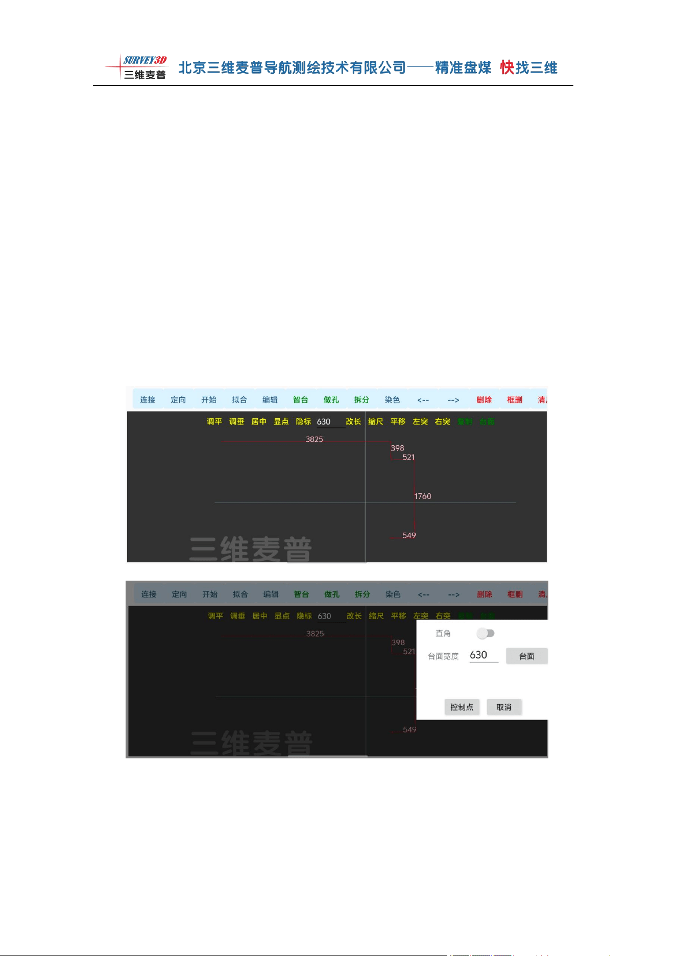
Smart Countertop: After scanning, the system automatically generates
contour line segments. First adjust the head and tail line segment lengths, and
clean up excess lines: select excess nodes to turn them yellow, and click [Delete]
to remove excess line segments. After dimension adjustment and line cleanup are
complete, click [Smart Countertop]. In the popup dialog, fill in the countertop
width according to your actual needs. After filling, confirm the countertop to
complete the creation.
Example: To create a 630 countertop, enter 630 in the dialog, then click [Smart
Countertop]. A popup dialog will appear. Fill in the countertop width as needed (in
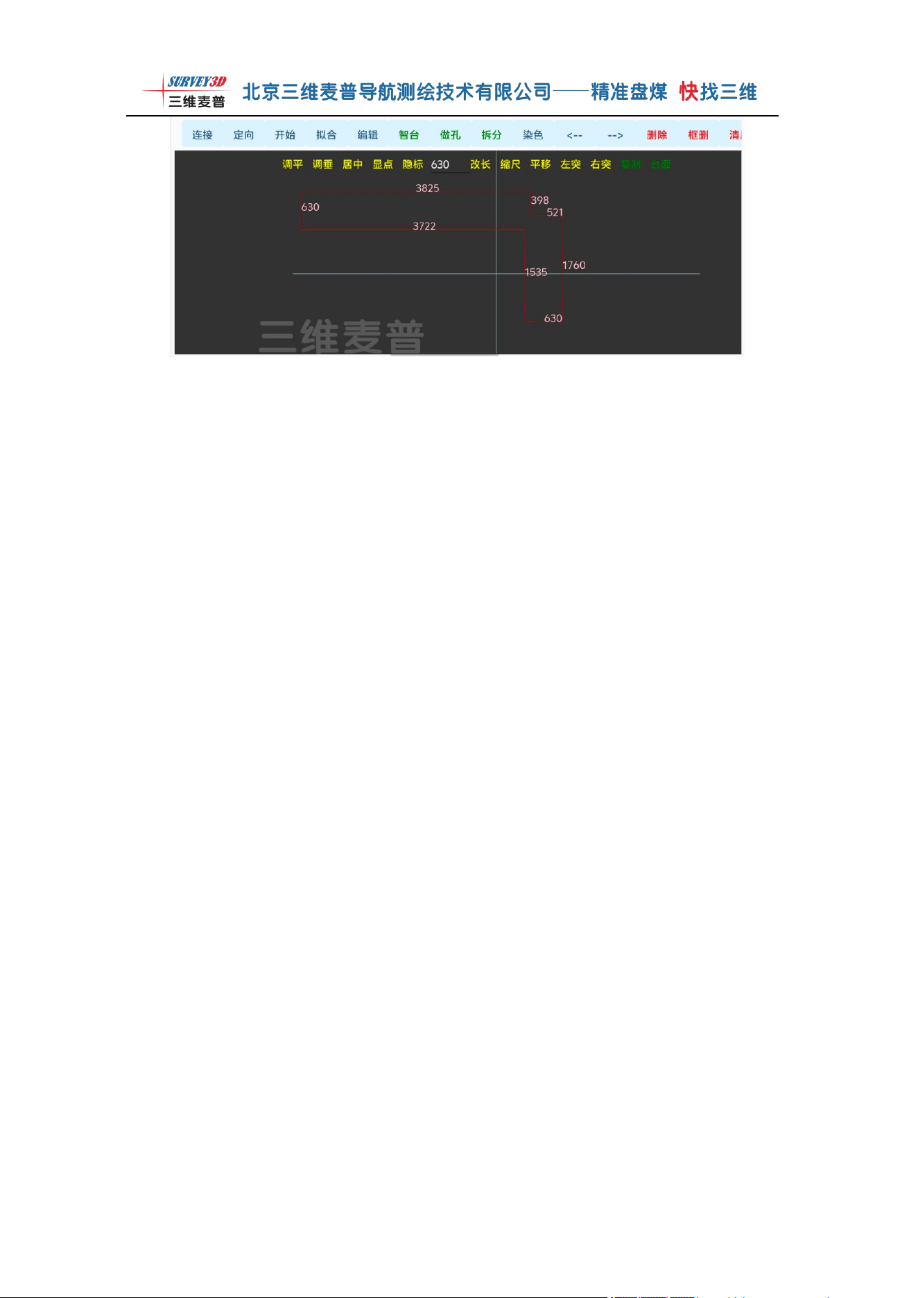
this case, 630), and click the countertop button to directly generate a 630-wide
countertop. See Figure 1-39.
第 38 页 共 57 页
Figure 1-39
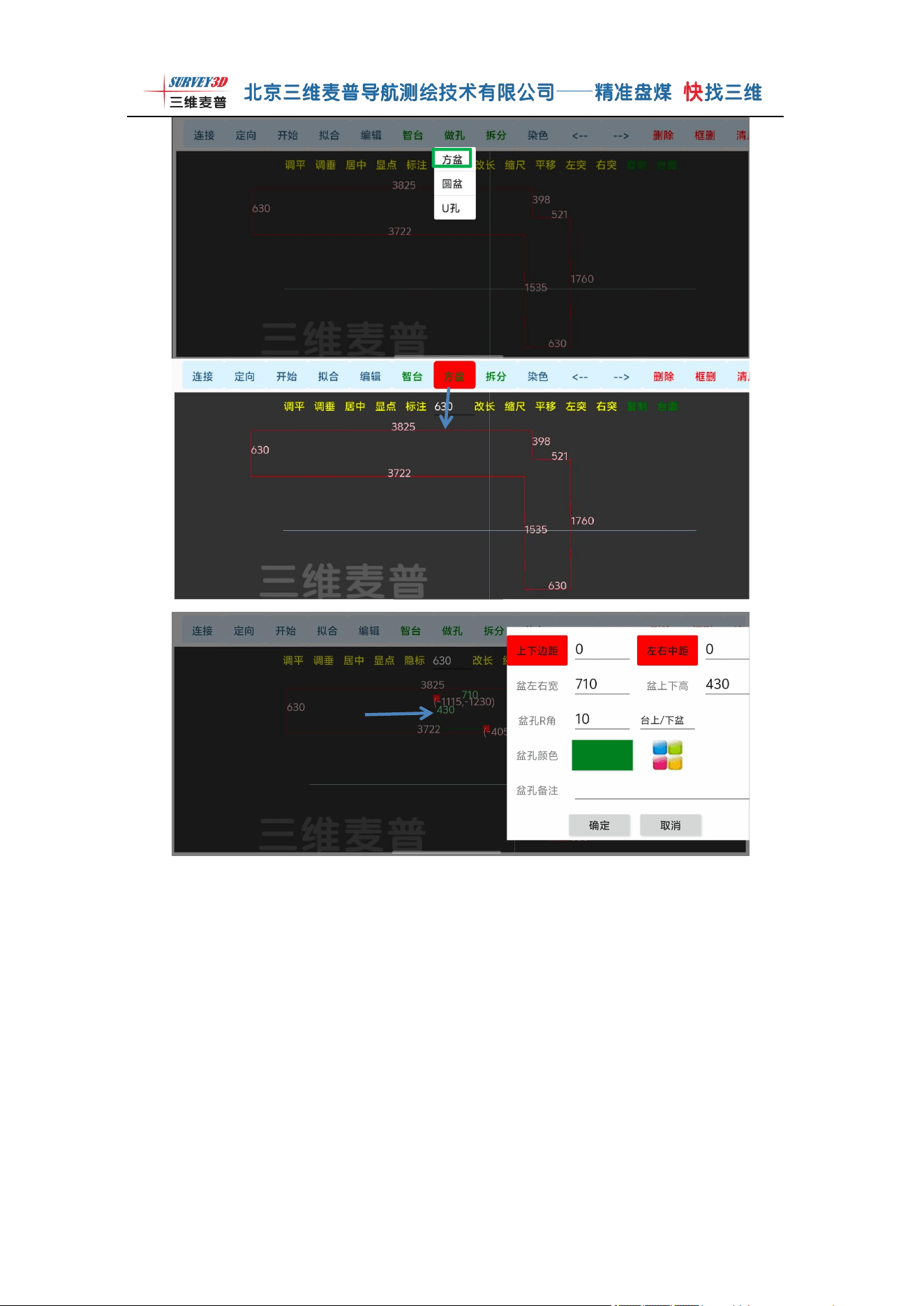
Make Hole: After the basic countertop shape is created, you can start
making sink holes. Click the [Make Hole] function to display a dropdown menu
with three built-in styles: square basin, round basin, and U-hole. You can drag
and drop the corresponding basin template as needed. Drag the basin template
to the countertop position and release, and a parameter setting window will
immediately pop up. Enter the upper and lower edge distances, left and right
center distances, basin left-right width, basin top-bottom height, basin hole R-
angle, and other data according to the actual on-site dimensions. After all
parameters are set, click [OK] to generate a complete countertop with sink hole.
Make Hole operation has four steps:
· Select upper and lower edge distances: Click the [Upper/Lower
Edge Distance] position, select the upper or lower wall line segment,
and enter the edge distance value;
· Select left and right center distances: Click the [Left/Right
Center Distance] position, select the left or right wall line
segment, and enter the center distance value;
· Set basin dimensions: Fill in the basin left-right width and
top-bottom height;
· Configure corners and installation mode: Enter the basin hole
R-angle parameter, then select one of three installation methods:
under-mount sink, above-counter sink, or drop-in sink.
Example: After selecting [Square Basin], [Make Hole] will automatically switch
to square basin mode. Drag the basin template to the center position on the countertop
and release. The square basin will appear, and the parameter setting interface will
immediately pop up. See the figure below.
第 39 页 共 57 页
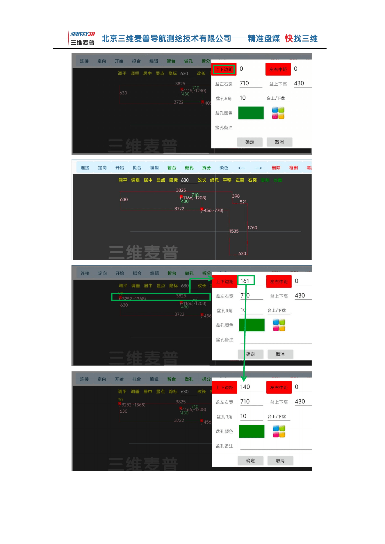
After the parameter setting interface appears, click the
[Upper/Lower Edge Distance] position. The page will automatically
switch back to the countertop view. Select the upper wall line
segment 3825, and two red positioning points will appear on the
interface. Then an upper and lower edge distance input box will pop
up. Change the default value of 161 to the actual dimension of 140.
See the figure below.
在这个空白位置进行拖拽一个方盆,出来方盆出来后松手
绿色线框 430*710 就是方盆
第 40 页 共 57 页
After entering 140, click the [Left/Right Center Distance]
position. The page will return to the countertop view again. Select
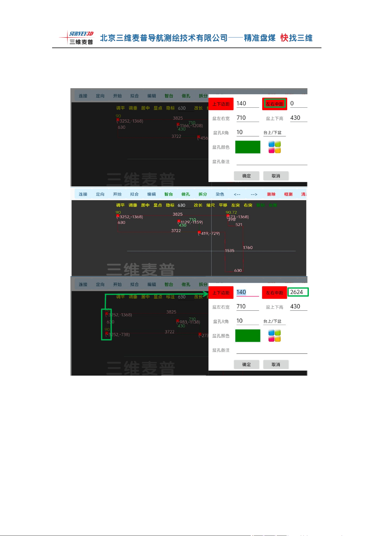
第 41 页 共 57 页
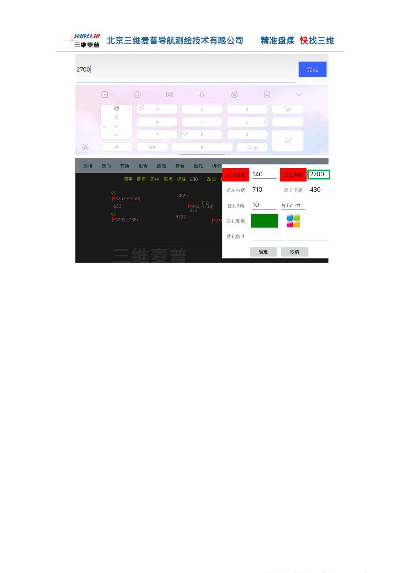
the left wall line segment on the 630 side, and two red positioning
points will appear on the interface. Then an input box will pop up.
Change the default value of 2624 to the actual dimension of 2700. See
the figure below.
第 42 页 共 57 页
第 43 页 共 57 页
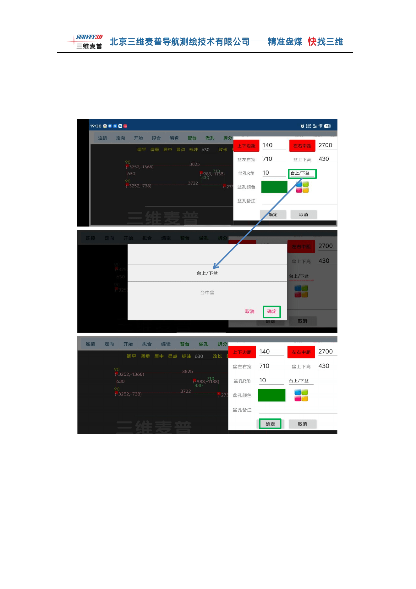
After completing the left/right center distance, fill in the
basin left-right width, basin top-bottom height, basin hole R-angle
value, and select above-counter/under-counter sink as needed. The
basin hole color can use the default value. Click OK to generate the
square basin. Note: The operation logic for making a pipe hole is the
same as for a basin hole, with identical steps. See the figure below.
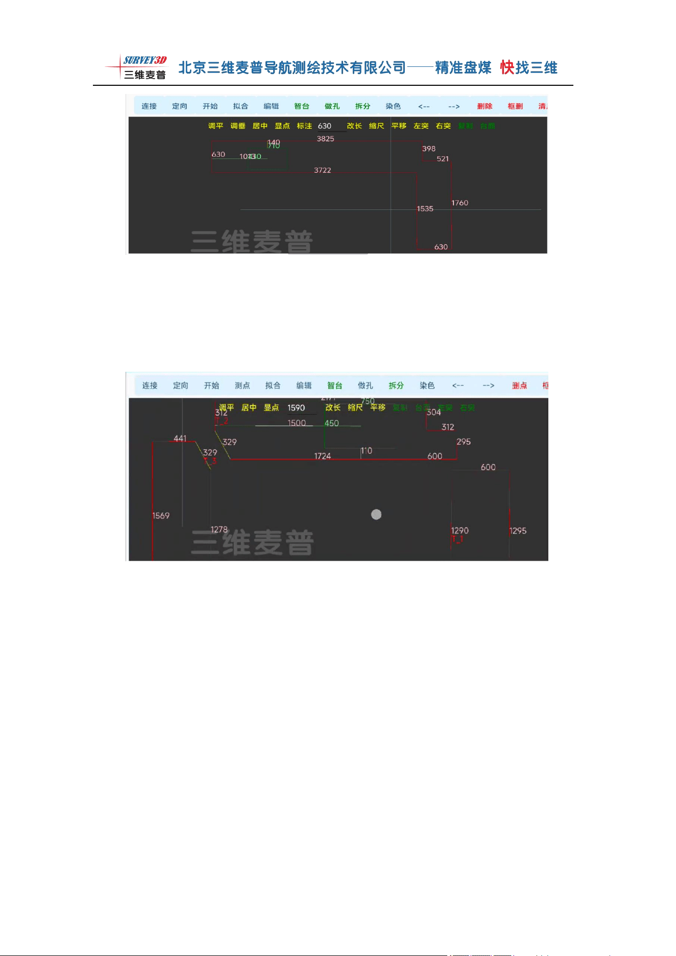
第 44 页 共 57 页
Split: Then proceed with panel splitting: Open the Edit dropdown menu, select
the Draw Line function to manually draw split lines. If you need a line to extend to
the right, first select the target line, click Extend in the Edit bar, and the line will
extend to the specified position. Then click Split to split the entire panel into multiple
pieces.
第 45 页 共 57 页
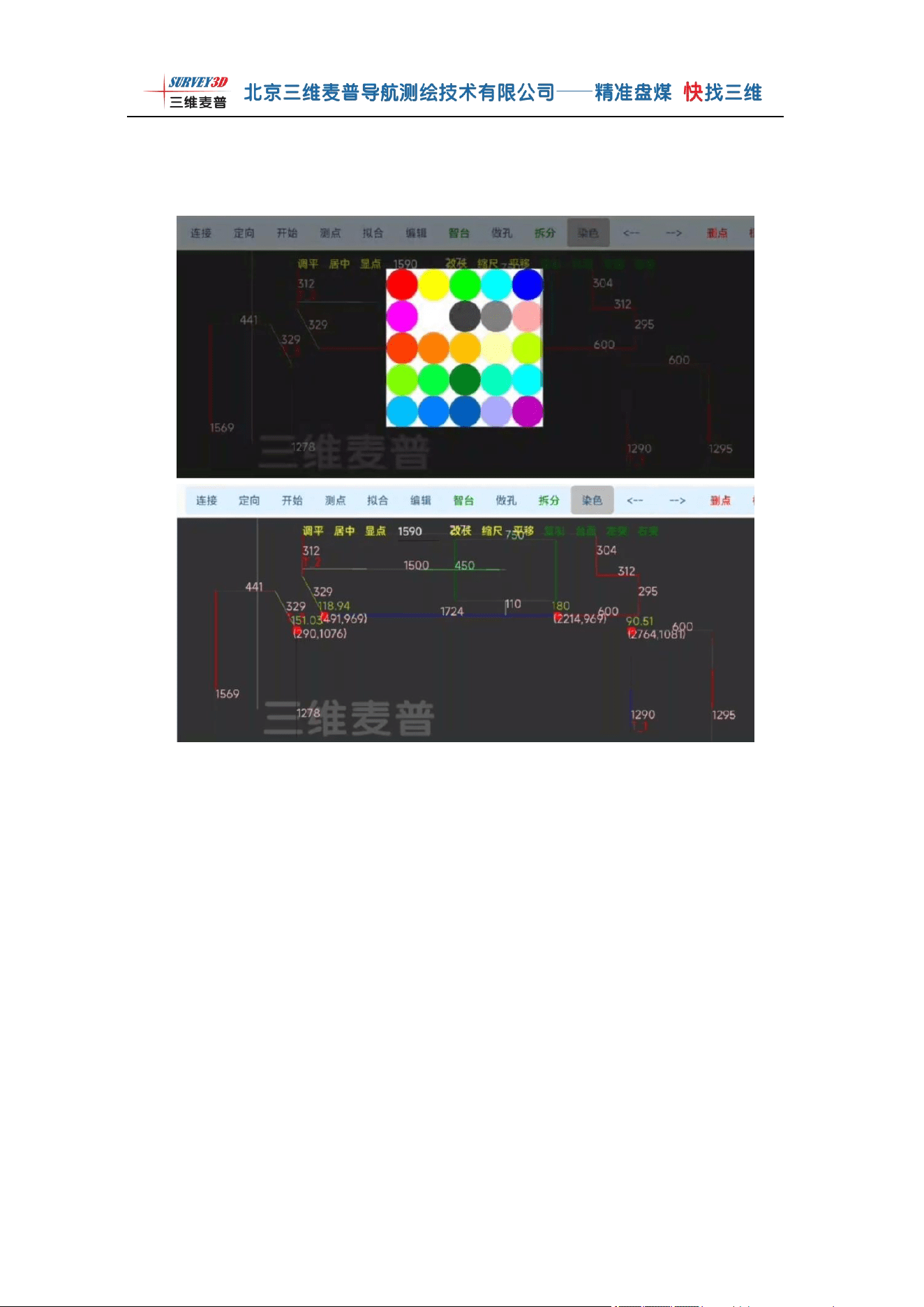
Color: After splitting, you can apply colors: Click the Color function and select
blue to apply color to the corresponding area. For the seam saw blade position, you
can change color number 329 to red. After adjustment, click Cancel to exit color
mode.
第 46 页 共 57 页
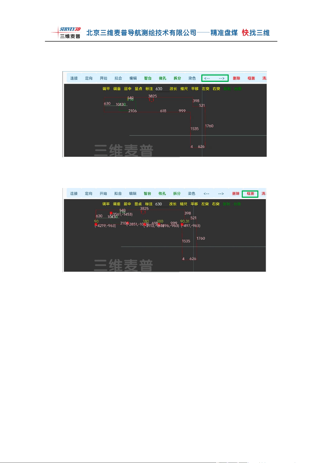
Left/Right Arrows: The left and right arrow buttons can be used to undo
mistaken operations or incorrect steps. After undoing, you can re-perform the
operation. See the example figure below.
Box Delete: When you need to delete multiple nodes or lines in batch, instead of
clicking them one by one, simply box-select the target content to delete them all at
once, making the operation more efficient. See the example figure below.
第 47 页 共 57 页
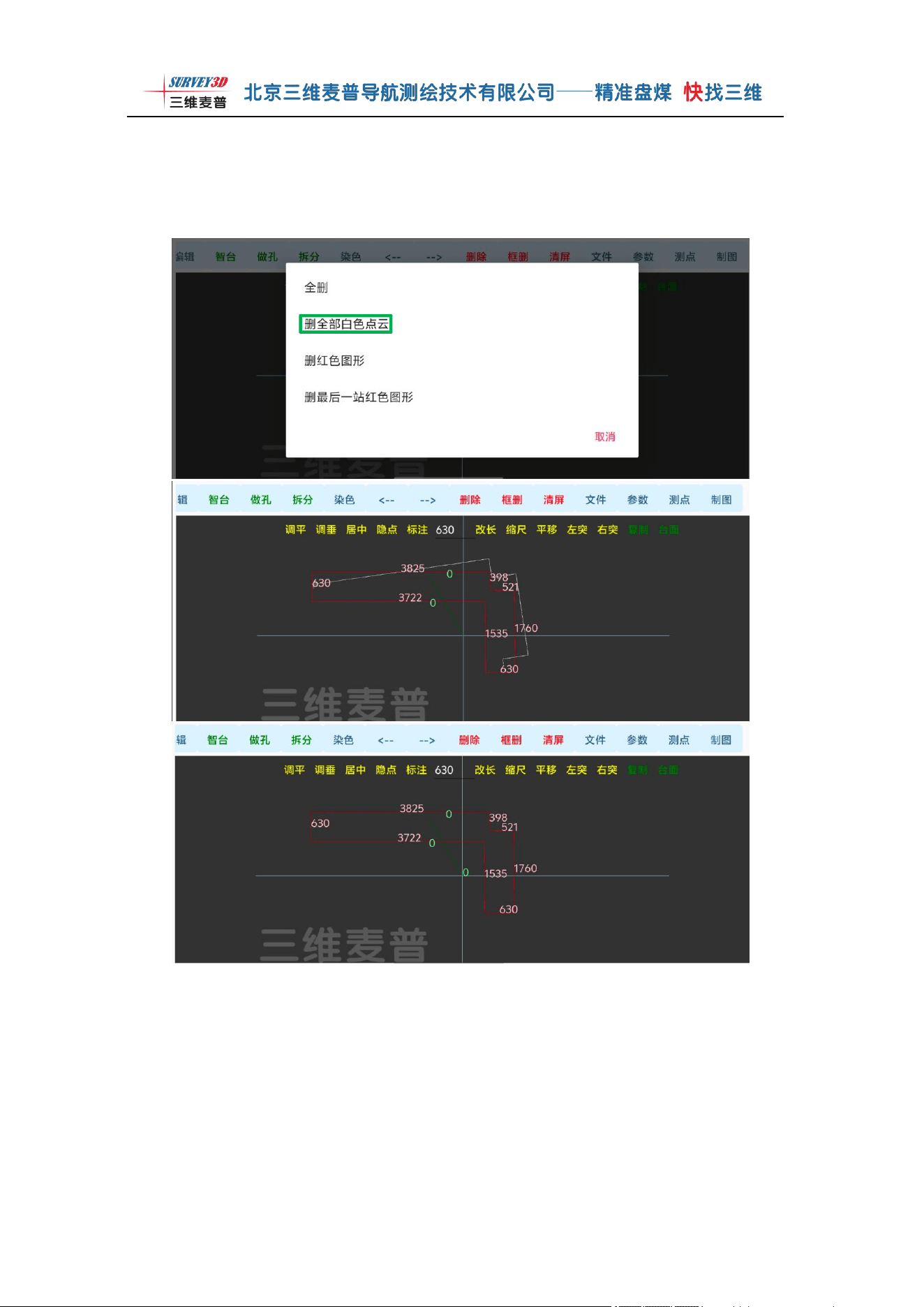
Clear Screen: Clear Screen provides four deletion modes: [Delete All], [Delete
All White Point Cloud], [Delete Red Graphics], [Delete Last Red Graphics]. You can
select the corresponding deletion method according to your actual operation needs.
After selection, click OK to complete the cleanup and deletion. See the example
figure below.
All white point cloud deleted
第 48 页 共 57 页
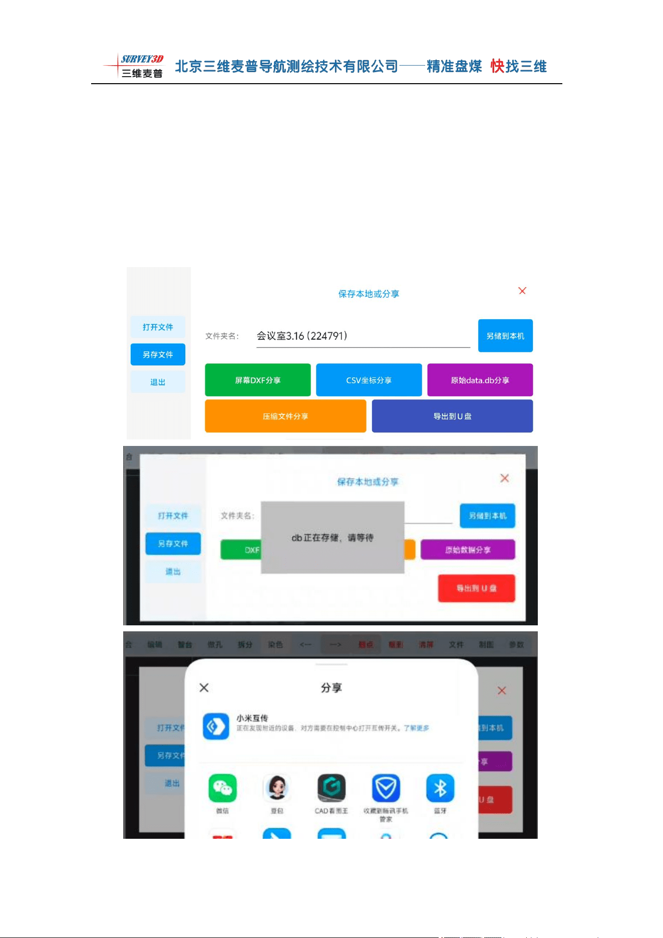
File: After the file is completed, you can save and share it. Select the drawing
from left to right, click the [File] button, and customize the name as "Community
Name + Building Unit Information". Click Save to Local. The system will
automatically generate three files: DXF, DX1, and DX2 for the entire drawing. If the
drawing has pipe holes, an additional patch file will be generated. To share, you can
directly send the entire set of files via WeChat. To export raw data, insert a USB drive
for one-click export. The entire drawing operation process is then complete.
第 49 页 共 57 页
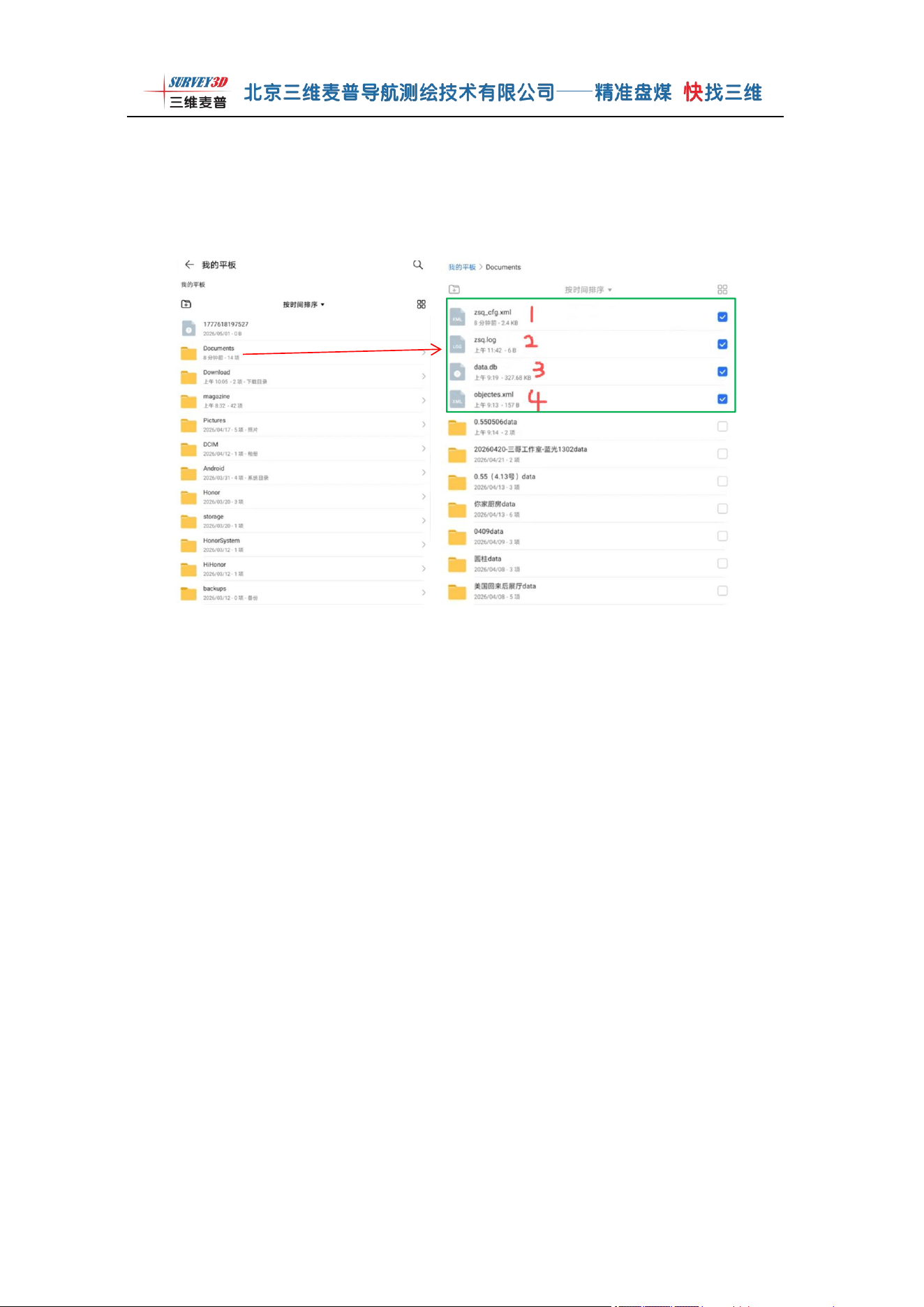
Chapter 4 How to Modify the Ranging Difference
When upgrading the software to a new version, uninstall the old program first, and
delete the four excess files in the document folder. See the figure below.
第 50 页 共 57 页
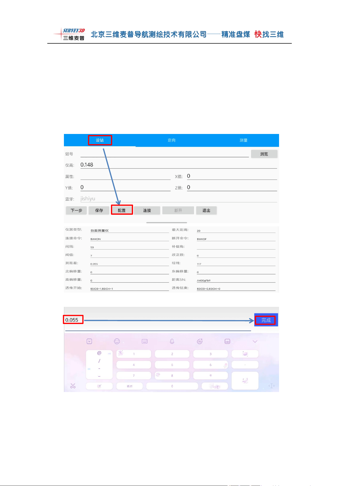
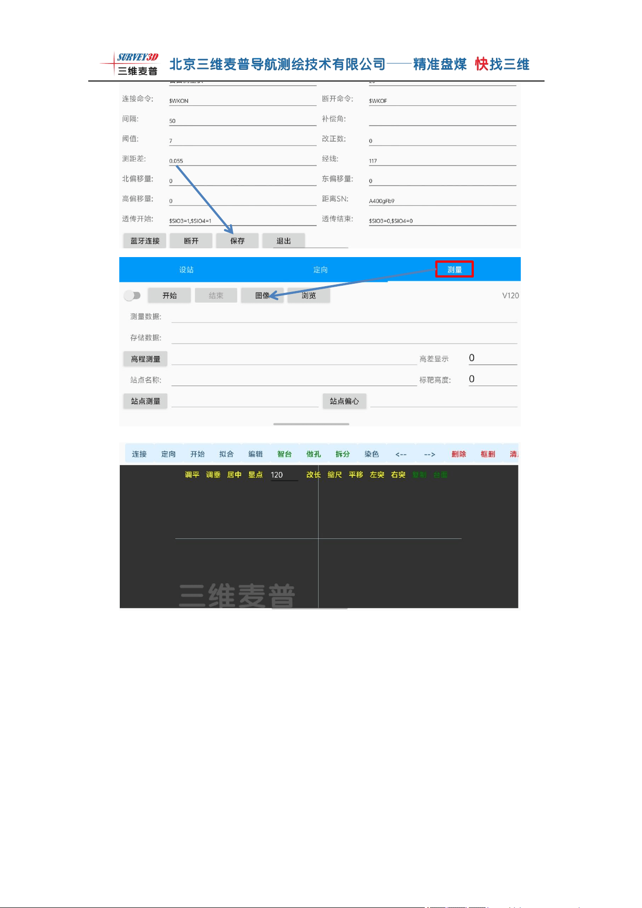
After deletion, open the Countertop APP program. After entering the APP main
interface, click Back (on some devices you can swipe left to return, and on some
interfaces click the less-than icon; use the actual device operation method to return).
Then click [Station Setup], find the [Configuration] option in the lower left corner of
the page and enter it. Change the ranging difference value to 0.055, and click Save after
modification. Then click [Measurement], find and open [Image] to return to the
measurement interface. The ranging difference parameter modification is now complete,
and the instrument can be used normally. Tip: If the instrument has been idle for a long
time, it is recommended to exit the APP program and re-enter before operating. See the
figure below.
第 51 页 共 57 页
第 52 页 共 57 页
Chapter 5 Advanced Features for Other Surveying
Industries (Reference When Needed)
1 Station Setup
The TM80 tabletop scanner has two methods for entering station coordinates
(method b is generally used):
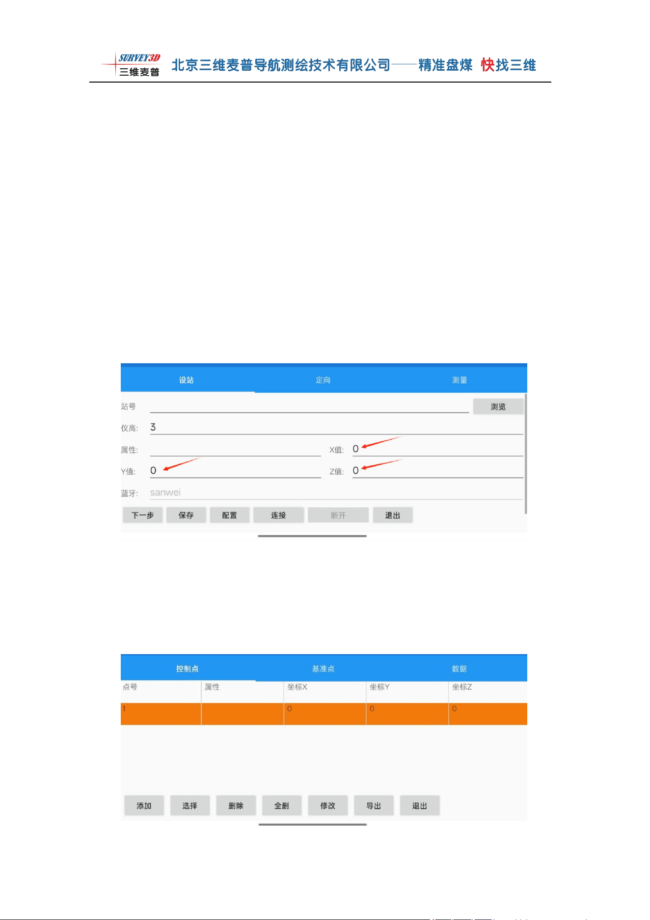
a. Click the blank space after X, Y, Z, and the system will automatically pop up
a soft keyboard interface. Switch between letter, number, pinyin, or English
input methods and enter the known coordinates. See the figure:
b. You can click the [Browse] button to call up point coordinate data. For the
first measurement, if there is existing data, click Delete All to clear the memory.
Then, on the control point interface, click the [Add] button, and the software will
automatically add a row of default point coordinate data. See the figure.
第 53 页 共 57 页
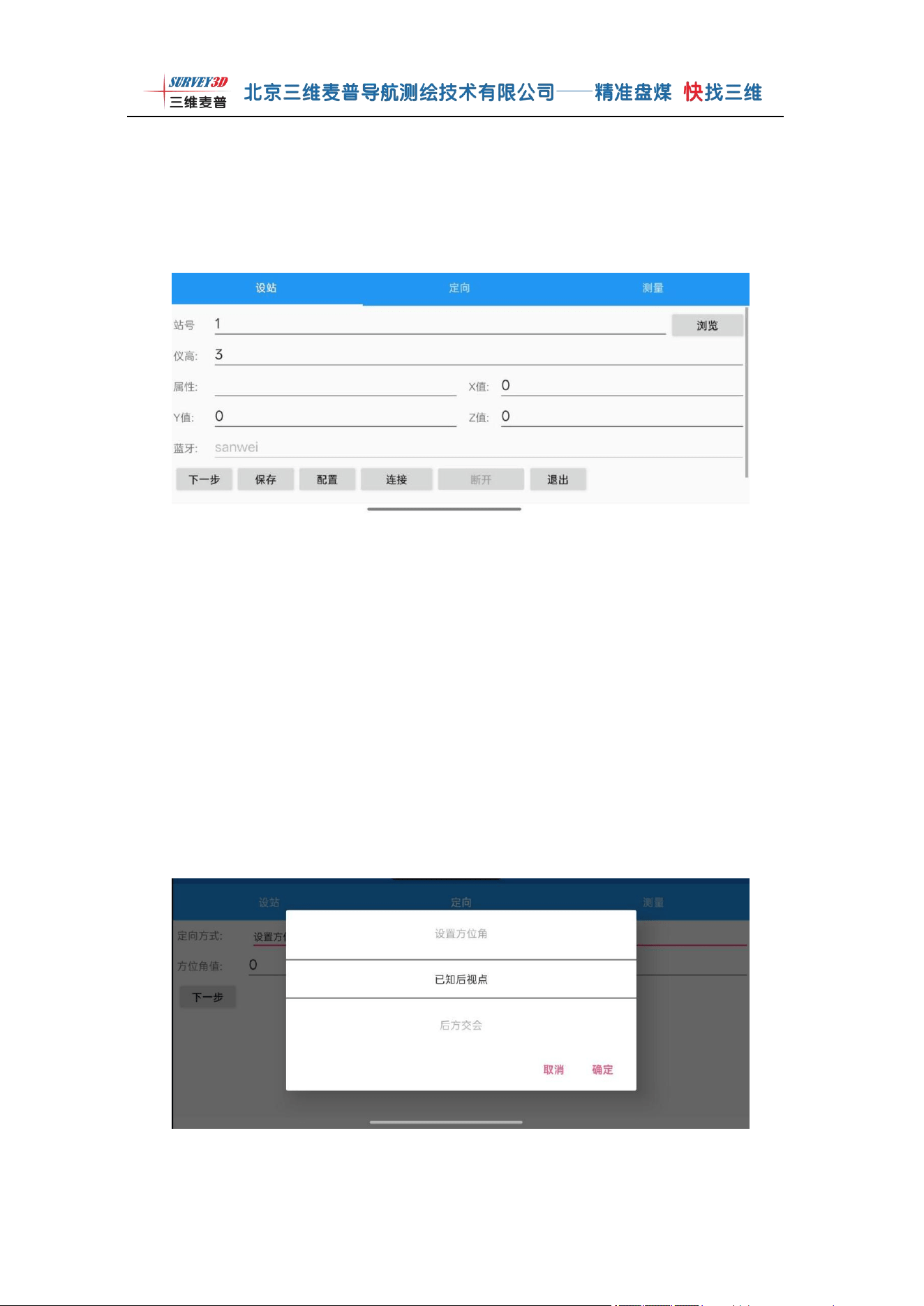
At this point, select the T:1 column information and click [Select]. The system will
automatically return to the station setup interface and connect all T:1 information from
data management to the station setup interface. See the figure:
Then click Next to enter the station setup interface.
Note: The X, Y, and Z values in the station setup interface can be modified directly,
but after modification, you must click Save. Although the data will take effect, the point
will not be displayed in Browse.
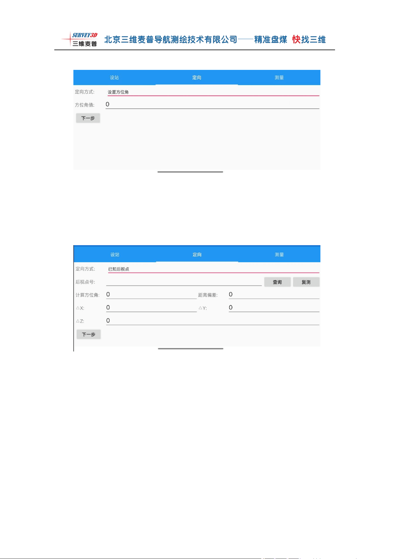
2 Orientation
After completing the station setup step, click Next to enter the orientation
interface. Click the orientation method, and three orientation methods will be
available for selection. See the figure:
a. Set Azimuth: Aim the laser red dot at the north direction, click [Next] to
第 54 页 共 57 页
complete orientation, and the program enters the measurement interface.
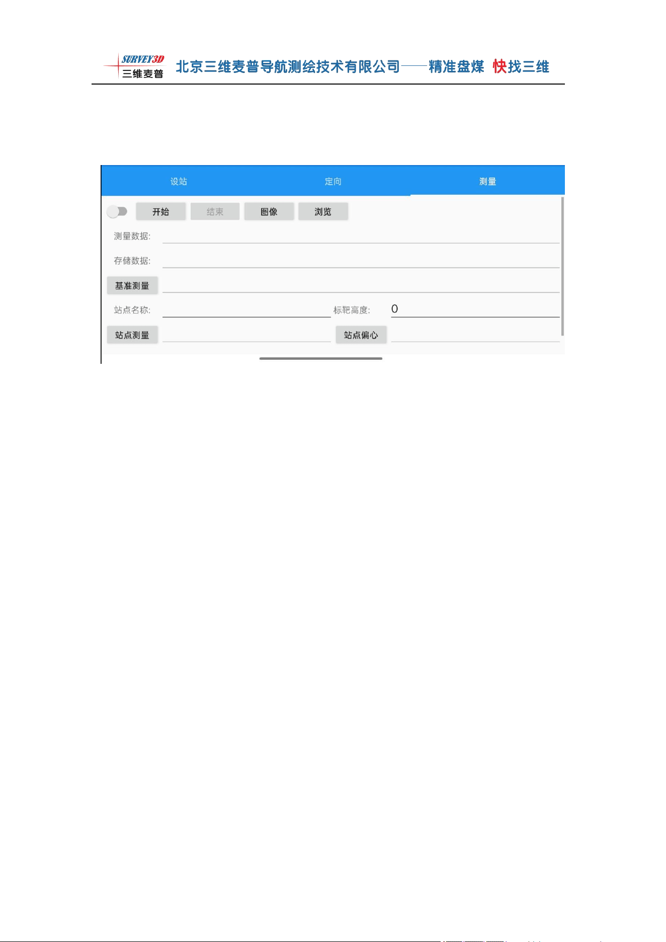
b. Known Backsight Point: First, place the instrument at a known point position.
During station setup, import that point's coordinates, then enter the station setup
interface. Click [Query] to select the required control point, then aim at it and click
[Resurvey]. See the figure, then click Next.
c. Resection: (This function is only used in surveying applications and is omitted
for now)
第 55 页 共 57 页
3 Measurement
Enter the measurement interface. See the figure:
Start: Start scanning. The instrument will automatically measure continuously (This
function is not yet available and is prohibited from use)
End: End scanning (This function is not yet available and is prohibited from use)
Image: Open the point cloud image interface (Do not view images when there is no
station measurement data)
Measurement Data: Angles and distances measured by the instrument
Stored Coordinates: Point numbers and coordinates already stored in memory (Data
appears only when Start is pressed)
Reference Measurement: Measure the reference surface height of the target
Station Name: Names for conveniently remembering each control point measured at a
station
Station Measurement: When one station cannot measure all sides of the target, this
function can be used to measure coordinates of other stations. This data is mainly used
for resection
Target Height: Height of the target
Browse: Query data in memory

第 56 页 共 57 页
Chapter 6 Product Warranty
Unless otherwise specifically stated by the company, the warranty period
for this equipment is twelve months from the date the user receives the
instrument. The instrument warranty is subject to the following terms:
(1) The company is not responsible for warranty coverage if equipment
failure or damage is caused by modifications made to the equipment at the
customer's request;
(2) Damage or failure caused by improper use, improper storage,
transportation, or power supply issues; any equipment damage or failure caused
by on-site or personal reasons of the user is not covered by warranty;
(3) The company is not responsible for free warranty if equipment is
damaged or fails due to unauthorized repairs or modifications without the
company's written consent;
(4) The instrument's accessories are also covered by the warranty.
In the event of equipment failure, the user should contact the company
promptly and notify the company of the equipment condition in writing or by
email, while keeping the equipment properly stored. For equipment that needs to
be shipped to the company for repair, the user is responsible for safely
transporting the equipment to the company's designated location and bearing the
associated costs. For issues caused by the equipment itself, the company provides
free repair during the warranty period. After repair, the company is responsible
for transporting the equipment to the user's designated location. After the
warranty period expires, the company will charge certain costs depending on the
situation.

This equipment has been tested and found to comply with the limits for a Class B digital device,
pursuant to part 15 of the FCC Rules. These limits are designed to provide reasonable protection
against harmful interference in a residential installation. This equipment generates, uses and can
radiate radio frequency energy and, if not installed and used in accordance with the instructions, may
cause harmful interference to radio communications. However, there is no guarantee that interference
will not occur in a particular installation. If this equipment does cause harmful interference to radio or
television reception, which can be determined by turning the equipment off and on, the user is
encouraged to try to correct the interference by one or more of the following measures:
•Reorient or relocate the receiving antenna.
•Increase the separation between the equipment and receiver.
•Connect the equipment into an outlet on a circuit different from that to which the receiver is
connected.
•Consult the dealer or an experienced radio/TV technician for help.
Caution: Any changes or modifications to this device not explicitly approved by manufacturer could
void your authority to operate this equipment.
This device complies with part 15 of the FCC Rules. Operation is subject to the following two
conditions: (1) This device may not cause harmful interference, and (2) this device must accept any
interference received, including interference that may cause undesired operation.
RF Exposure Information
The device has been evaluated to meet general RF exposure requirement. The device can be used in
portable exposure condition without restriction.
FCC Statement