INSTALLATION &
OPERATION MANUAL
CHEESEMELTER - 1024, 1036, 1048
MODELS:
1024C ML-103833
1024W ML-103834
1024P ML-103835
1036C ML-103836
1036W ML-103837
1036P ML-103838
1048C ML-103839
Canadian ML-126600
1048W ML-103840
Canadian ML-126602
1048P ML-103841
Canadian ML-126601
F-33225 Rev. B (03-23)Vulcan is a division of ITW Food Equipment Group | 3600 North Point Blvd., Baltimore, MD 21222
TECHNICAL SERVICE AND PARTS ASSISTANCE - US: 1-800-814-2028 | CANADA: 1-800-444-4764
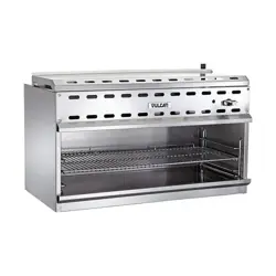
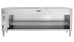
Model 1024


– 3 –
TABLE OF CONTENTS
GENERAL............................................................................................................................................. 4
Specifications ........................................................................................................................... 4
INSTALLATION.................................................................................................................................... 5
Unpacking................................................................................................................................. 5
Location .................................................................................................................................... 5
Installation Codes and Standards ........................................................................................... 6
Wall Mounting........................................................................................................................... 6
Heater Installation .................................................................................................................... 8
Rack Installation....................................................................................................................... 8
Electrical Connections ............................................................................................................. 9
OPERATION ...................................................................................................................................... 10
Cleaning.................................................................................................................................. 10
TROUBLESHOOTING ....................................................................................................................... 11
© Vulcan
– 4 –
OPERATION & INSTALLATION
MODELS 1024,1036,1048
CHEESEMELTERS
PLEASE KEEP THIS MANUAL FOR FUTURE USE
GENERAL
Vulcan-Hart Cheesemelters are produced with quality workmanship and material. Proper installation,
usage, and maintenance of your cheesemelter will result in many years of satisfactory performance.
Thoroughly read this entire manual and carefully follow all of the instructions provided.
The cheesemelter is designed for either countertop or wall mounted operation, and is also available
in a pass through (backless) version for countertop use only. It can also be used for finishing, glazing,
or to keep food warm.
SPECIFICATIONS
MODELS 1024C 1024W 1024P 1036C 1036W 1036P 1048C 1048W 1048P
DIMENSIONS
Width Inches 27 27 27 36
1
⁄2 36
1
⁄2 36
1
⁄2 50 50 50
(mm) (686) (686) (686) (927) (927) (927) (1270) (1270) (1270)
Depth Inches 17
1
⁄4 17
1
⁄4 16 17
1
⁄4 17
1
⁄4 16 17
1
⁄4 17
1
⁄4 16
(mm) (438) (438) (406) (438) (438) (406) (438) (438) (406)
Height Inches 19
1
⁄4 15
1
⁄4 19
1
⁄4 19
1
⁄4 15
1
⁄4 19
1
⁄4 19
1
⁄4 15
1
⁄4 19
1
⁄4
(mm) (489) (387) (489) (489) (387) (489) (489) (387) (489)
INPUT POWER ALL: 208 or 240 Volts, 50-60 Hz., Single Phase
REQUIREMENTS 2.4 KW 2.4 KW 2.4 KW 3.6 KW 3.6 KW 3.6 KW 4.2 KW 4.2 KW 4.2 KW
(Canadian) (4.0 KW) (4.0 KW) (4.0 KW)
HEATING 222222444
ELEMENTS 1200 W 1200 W 1200 W 1800 W 1800 W 1800 W 1050 W 1050 W 1050 W
(Canadian) (1000 W) (1000 W) (1000 W)
© Vulcan
– 5 –
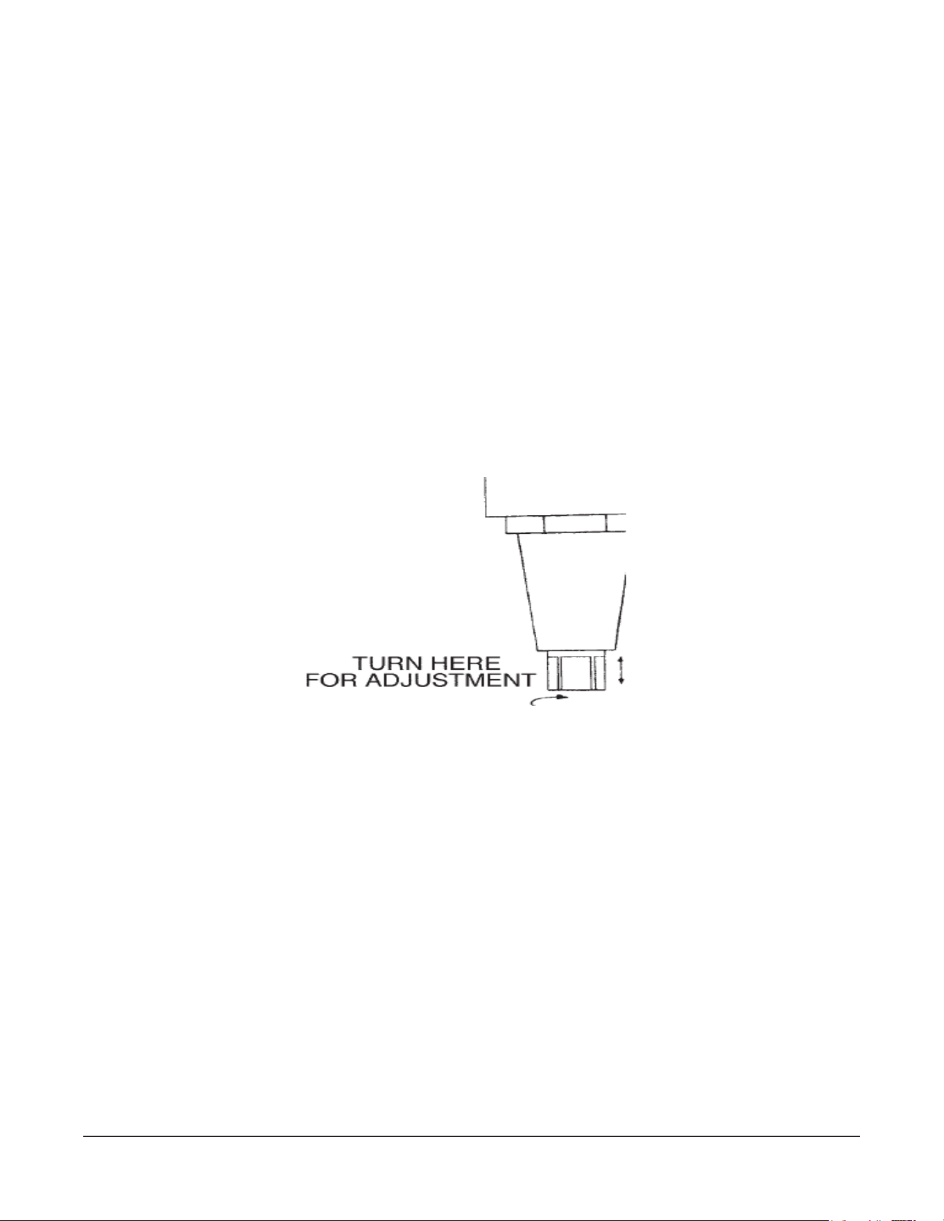
UNPACKING: This unit was inspected before leaving the factory. The carrier assumes full responsibility for the
safe delivery upon acceptance of the shipment. Check for possible shipping damage immediately after receipt. If the
unit is found to be damaged, complete the following steps:
1. Carrier must be notified within 5 business days of receipt.
2. Carrier’s local terminal must be notified immediately upon discovery (note time, date, and who was spoken to),
and follow up and confirm with written or electronic communication.
3. All original packing materials must be kept for inspection purposes.
4. The unit cannot have been moved, installed, or modified.
5. Notify Vulcan Customer Service immediately at 800-814-2028 of any missing or damage
LOCATION
Do not install pass through cheesemelters on a wall. Pass through cheesemelters must be installed
with adequate clearances for servicing and proper operation.
Do not operate countertop and pass through cheesemelters without the legs in place. Damage to the
countertop may result.
It is recommended that the cheesemelter not be installed directly over or directly adjacent to charbroilers,
griddles or fryer banks. Quartz elements can be susceptible to the effects of grease laden smoke and
installation in these locations
may shorten element life. The cheesemelter must be installed so that it is
level side to side and front to back
© Vulcan

– 6 –
INSTALLATION CODES AND STANDARDS
The cheesemelter must be installed in accordance with:
In the United States of America:
1. State and local codes.
2. National Electrical Code, ANSI/NFPA-70 (latest edition). Copies may be obtained from The
National Fire Protection Association, Batterymarch Park, Quincy, MA 02269.
In Canada:
1. Local codes.
2. Canadian Electric Code, CSA C22.1 (latest edition). Copies may be obtained from The Canadian
Standard Association, 178 Rexdale Blvd., Etobicoke, Ontario, Canada M9W 1R3.
WALL MOUNTING (MODELS 1024, 1036 & 1048W ONLY)
1. Remove the two back retaining bolts on the bottom of the cheesemelter along the rear.
2. Pry out the back from the bottom of the cheesemelter.
3. Remove the back by pulling out and down.
4. Remove (but DO NOT discard) the insulation.
5. Use the back as a template to locate holes for wall attaching lag bolts.
6. Fasten the back to the wall with lag bolts or with anchor fasteners (not provided). Make sure that
the back is level and securely fastened.
7. Replace the insulation.
8. Hang the cheesemelter onto the wall mounted back.
9. Replace the two back retaining bolts in the bottom of the cheesemelter.
© Vulcan

– 7 –
© Vulcan
– 8 –
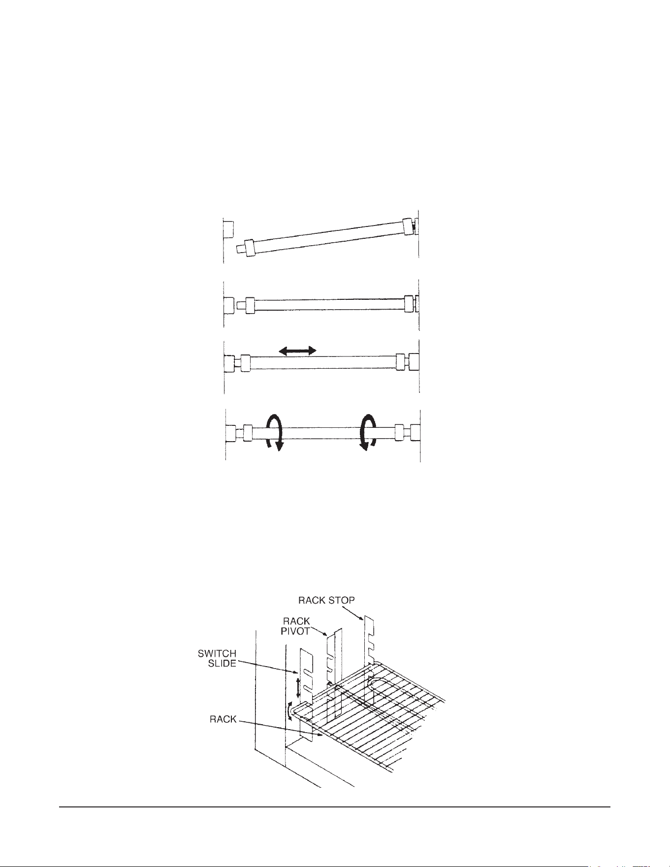
HEATER INSTALLATION
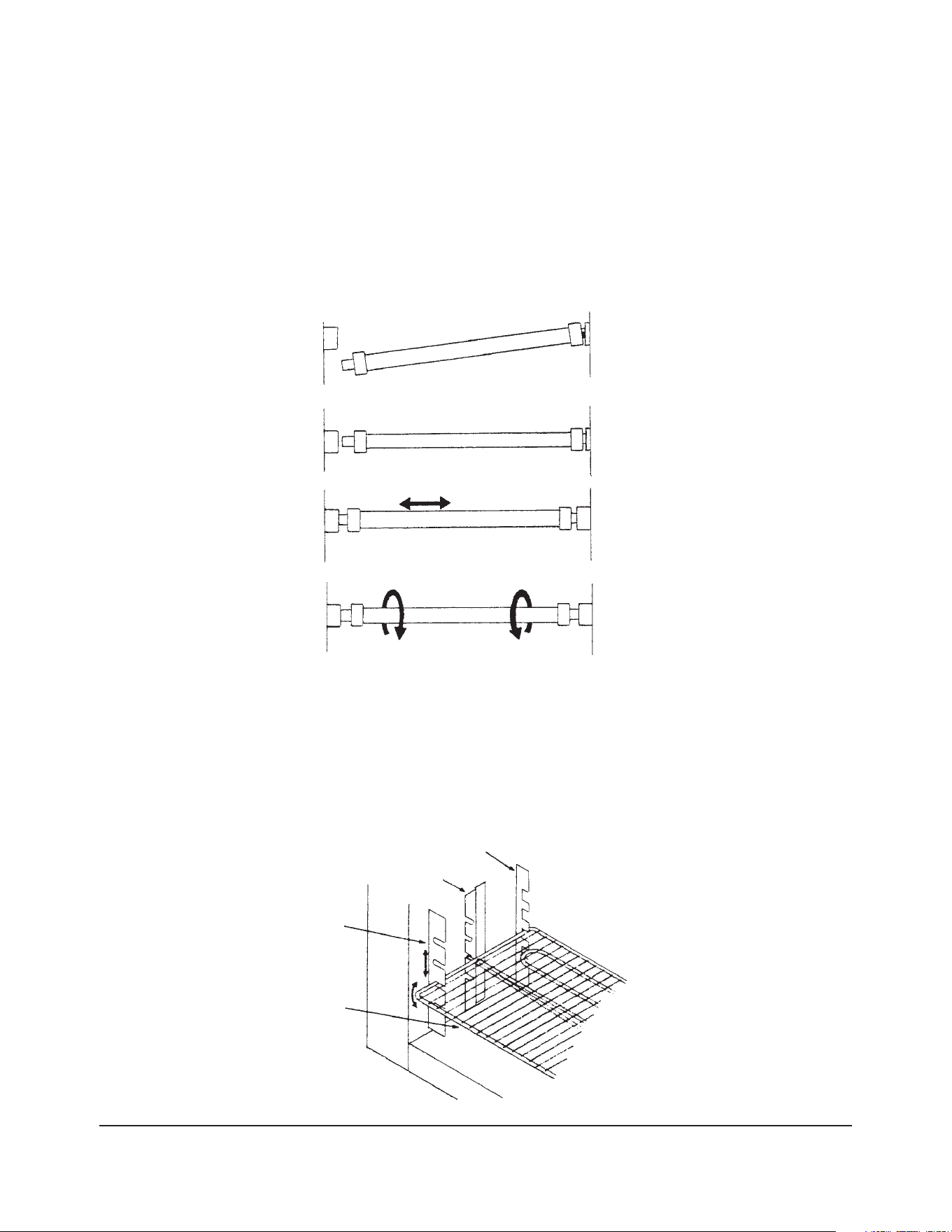
1. Push one end of the heater into one socket as far as it will go.
2. Swing the other end of heater up until it lines up with the opposite socket.
3. Release heater and it will snap into place.
4. Grasp the heater and move it back and forth to ensure that it is centered correctly.
5. Rotate the heater clockwise, then counterclockwise, to ensure that it is seated correctly.
RACK INSTALLATION
1. Insert the rack by placing the left pivot point just behind the switch slide.
2. Line up the rack evenly and push it straight back until the pivot points can be inserted into the
rack pivots.
3. The rack should tilt smoothly and readily.
© Vulcan

– 9 –
ELECTRICAL CONNECTIONS
WARNING: ELECTRICAL AND GROUNDING CONNECTIONS MUST COMPLY WITH THE
APPLICABLE PORTIONS OF THE NATIONAL ELECTRICAL CODE AND/OR OTHER LOCAL
ELECTRICAL CODES.
WARNING: DISCONNECT ELECTRICAL POWER SUPPLY AND PLACE A TAG AT THE
DISCONNECT SWITCH TO INDICATE YOU ARE WORKING ON THE CIRCUIT.
Two 1" (25 mm) knockouts are provided at the left rear for conduit installation. The terminal block and
grounding lug are located behind the access cover on the left side.
© Vulcan

– 10 –
OPERATION
WARNING: THE CHEESEMELTER AND ITS PARTS ARE HOT. BE VERY CAREFUL WHEN
OPERATING, CLEANING, OR SERVICING THE CHEESEMELTER.
1. Push the main switch to ON.
• Pilot lights.
• Cooling fan runs.
2. Place the product on the front of the rack. The heaters will automatically come on full power.
• If the heaters do not come on full power when the product is placed on the rack:
a. Be sure that the product is on the front half of the rack. The rack is balanced to trip the
actuating switch, but the weight must be on the front half of the rack to trip the switch.
b. Check that the rack is at same level on both sides and is correctly inserted.
c. If the rack operates freely, the failure of the actuating switch is the probable cause.
Contact your local Vulcan-Hart servicer.
3. Remove the product.
• Heaters will revert to “standby” with 25% of its heat on. (A slight glow may be visible.)
On the 1048, one or both of the two top switches must be on before the heaters will light.
• Top switch is for the left side.
• Bottom switch is for the right side.
The amount of heat may be changed by changing the rack height.
• Lower levels are for food warming.
• Upper levels are for finishing, glazing, or cheese melting.
CLEANING
WARNING: DISCONNECT ELECTRICAL POWER SUPPLY BEFORE CLEANING.
1. Allow cheesemelter to cool before cleaning.
2. Clean cheesemelter with soap and water, rinse, and dry with a soft dry cloth.
3. Remove rack and clean as you would any normal utensil.
The heaters are self-cleaning. DO NOT immerse heaters in water.
© Vulcan

– 11 –
TROUBLESHOOTING
IF THE CHEESMELTER BLOWS A FUSE OR TRIPS A CIRCUIT BREAKER
1.Check the capacity of the circuit.
2.Contact your local Hobart Food Equipment Group office.
IF THE HEATERS DO NOT LIGHT
1.If the pilot light does not come on, and the cooling fan does not run, check for a blown fuse or
an open circuit breaker.
2.If the pilot light is lit, and the cooling fan is running, but the heaters do not light, the cheesemelter
may be in standby. When cheesemelter is in standby with no product on the rack, the heaters may
not glow, but will still emit some heat.
3.If one heater is lit, but the other is not, a burnout or a loose connection is the probable cause.
Contact your local Hobart Food Equipment Group office.
IF THE COOLING FAN DOES NOT RUN
1.If the pilot light is not lit, and the heaters do not light, check for a blown fuse or an open circuit
breaker.
2.If the pilot light is lit and the heaters function, the probable cause is a loose connection. Contact
your local Hobart Food Equipment Group office.
© Vulcan

– 12 –
NOTES
© Vulcan
MODE D’EMPLOI
SALAMANDRES 1024, 1036, 1048
MODÈLES:
1024C ML-103833
1024W ML-103834
1024P ML-103835
1036C ML-103836
1036W ML-103837
1036P ML-103838
1048C ML-103839
Canadian ML-126600
1048W ML-103840
Canadian ML-126602
1048P ML-103841
Canadian ML-126601
F-
33225 Rev. B (03-23) IMPRIMÉ AUX É.-U.
Vulcan is a division of ITW Food Equipment Group | 3600 North Point Blvd., Baltimore, MD 21222
SERVICE TECHNIQUE ET ASSISTANCE EN PIÈCES - US: 1-800-814-2028 | CANADA: 1-800-444-4764
Modèle 1024
© Vulcan

– 2 –
© Vulcan

– 3 –
TABLE DES MATIÈRES
GÉNÉRALITÉS .................................................................................................................................... 4
Caractéristiques ....................................................................................................................... 4
INSTALLATION.................................................................................................................................... 5
Déballage.................................................................................................................................. 5
Emplacement............................................................................................................................ 5
Codes d’installation et normes ................................................................................................ 6
Montage mural ......................................................................................................................... 6
Installation des éléments chauffants....................................................................................... 8
Installation de la grille .............................................................................................................. 8
Raccordement électrique......................................................................................................... 9
FONCTIONNEMENT ......................................................................................................................... 10
Nettoyage ............................................................................................................................... 10
DÉPANNAGE ..................................................................................................................................... 11
© Vulcan
– 4 –
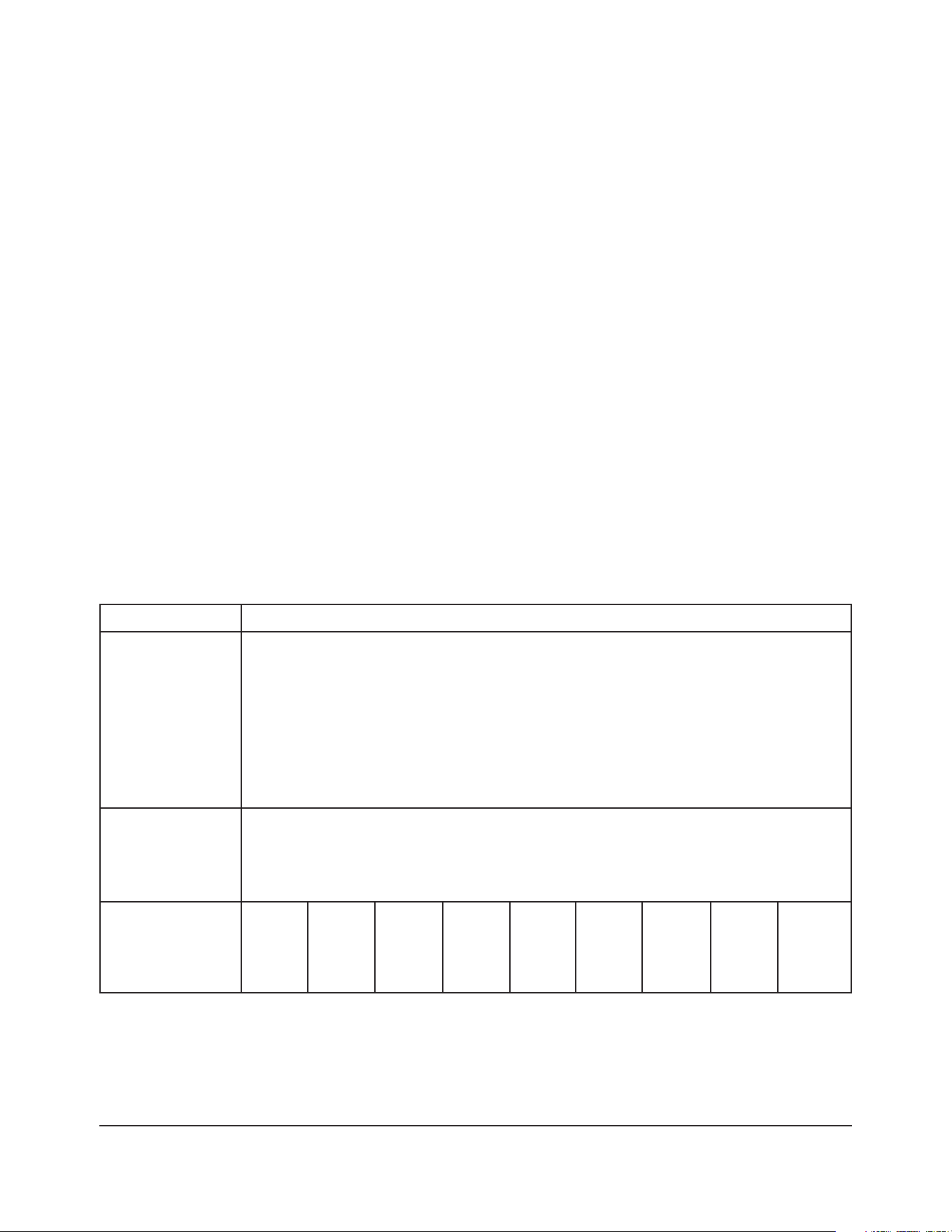
CARACTÉRISTIQUES
MODÈLE 1024C 1024W 1024P 1036C 1036W 1036P 1048C 1048W 1048P
DIMENSIONS
Largeur 686 686 686 927 927 927 1270 1270 1270
mm (po) (27) (27) (27) (36 1/2) (36 1/2) (36 1/2) (50) (50) (50)
Profondeur 438 438 406 438 438 406 438 438 406
mm (po) (17 1/4) (17 1/4) (16) (17 1/4) (17 1/4) (16) (17 1/4) (17 1/4) (16)
Hauteur 489 387 489 489 387 489 489 387 489
mm (po) (19 1/4) (15 1/4) (19 1/4) (19 1/4) (15 1/4) (19 1/4) (19 1/4) (15 1/4) (19 1/4)
ALIMENTATION TOUS LES MODÈLES : Courant monophasé de 208 ou 240 V, 50-60 Hz
2,4 kW 2,4 kW 2,4 kW 3,6 kW 3,6 kW 3,6 kW 4,2 kW 4,2 kW 4,2 kW
(Canada) (4,0 kW) (4,0 kW) (4,0 kW)
ÉLÉMENTS 222222444
CHAUFFANTS 1200 W 1200 W 1200 W 1800 W 1800 W 1800 W 1050 W 1050 W 1050 W
(Canada) (1000 W) (1000 W) (1000 W)
Installation et fonctionnement
SALAMANDRES
1024, 1036 ET 1048
DOCUMENT À CONSERVER EN CAS DE BESOIN.
GÉNÉRALITÉS
Les appareils Vulcan sont fabriqués avec le plus grand soin et à partir des meilleurs matériaux. Leur
installation, utilisation et entretien appropriés permettront d’en obtenir un rendement optimal pendant
de nombreuses années.
On recommande de lire ce manuel au complet et de suivre attentivement toutes les instructions.
Ces appareils s’installent sur un comptoir ou au mur et sont aussi offerts en modèles passe-plats
(c.-à-d. sans panneau arrière) pour l’utilisation sur un comptoir seulement. Ils permettent de dorer,
glacer ou simplement garder les aliments au chaud.
© Vulcan
– 5 –
INSTALLATION
DÉBALLAGE
Cet appareil a été inspecté avant de quitter l’usine. En acceptant de livrer cette marchandise, le
transporteur en assume l’entière responsabilité jusqu’à la livraison. Immédiatement après avoir
déballé l’appareil, vérifier s’il n’a pas été endommagé lors du transport. En cas de dommages,
conserver le matériel d’emballage et aviser le transporteur dans les sept jours suivant la date de
réception.
1. Déballer l’appareil et enlever tout le matériel d’emballage.
• L’élément chauffant et les pieds des modèles de comptoir et passe-plats de même que les
éléments chauffants des modèles muraux sont emballés et maintenus en place sur la sole
de la salamandre.
2. Visser les quatre pieds des modèles de comptoir et passe-plats.
3. Placer l’appareil sur une surface droite et horizontale à l’endroit désiré.
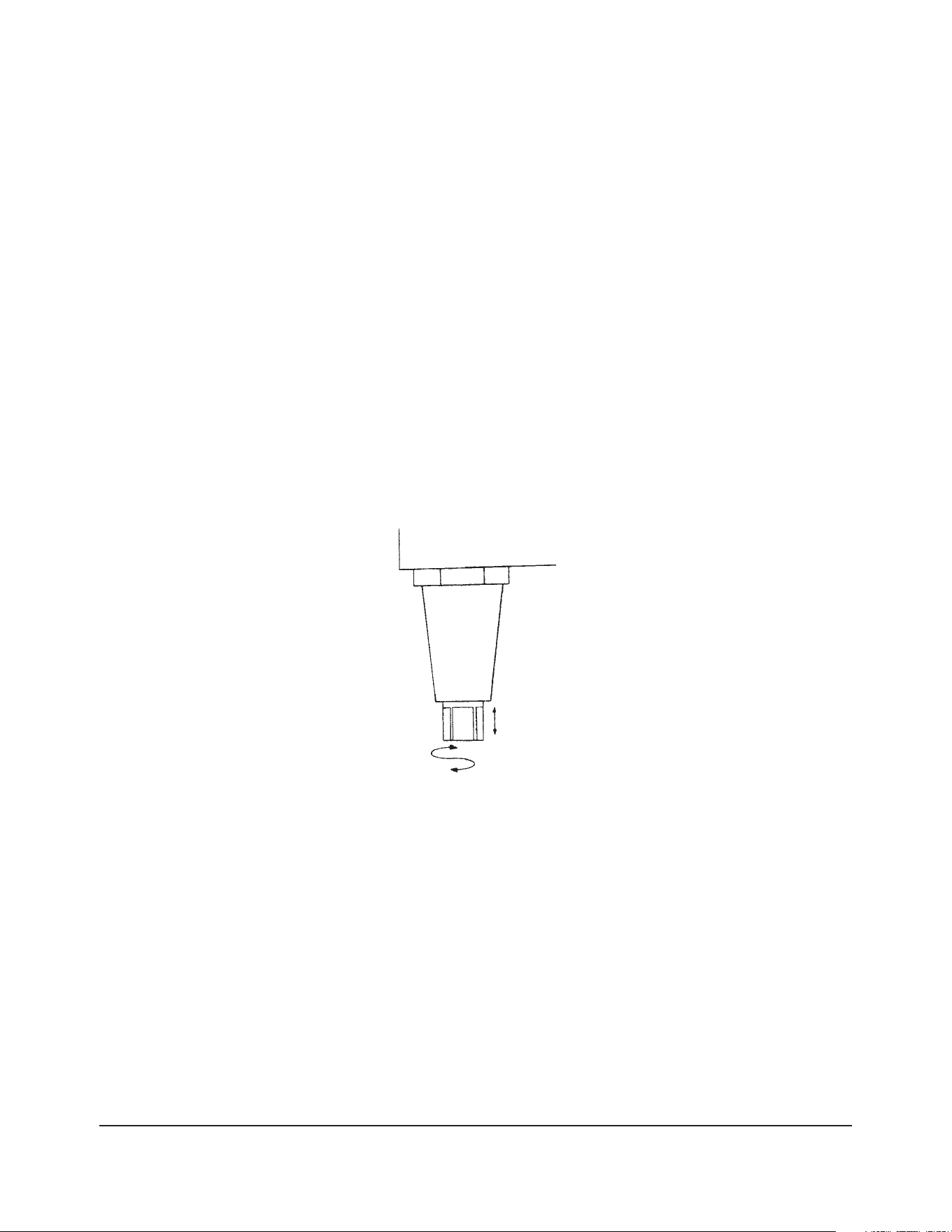
4. Niveler l’appareil (au besoin) en vissant ou dévissant la partie inférieure réglable des pieds.
Se reporter à l’illustration ci-dessous.
EMPLACEMENT
Ne pas installer les salamandres passe-plats au mur, mais dans un endroit suffisamment espacé pour
en permettre l’entretien et le fonctionnement approprié.
S’assurer que les pieds des modèles de comptoir et passe-plats sont en place avant d’utiliser ces
appareils, faute de quoi le comptoir risque d’être endommagé.
TOURNER ICI POUR LE
NIVELAGE DE L’APPAREIL
© Vulcan

– 6 –
CODES D’INSTALLATION ET NORMES
L’installation de ces salamandres doit se faire selon les codes suivants :
Aux États-Unis :
1. Codes locaux.
2. Norme ANSI/NFPA n° 70 (dernière édition) du National Electrical Code disponible auprès de la
National Fire Protection Association, Batterymarch Park, Quincy, MA 02269.
Au Canada :
1. Codes locaux.
2. Norme CSA-C22.1 (dernière édition) du Code canadien de l’électricité dont on peut se procurer
un exemplaire auprès de l’Association canadienne de normalisation, 178 Rexdale Blvd.,
Etobicoke (Ontario) M9W 1R3.
MONTAGE MURAL (MODÈLES 1024, 1036 & 1048W SEULEMENT)
1. Enlever les deux vis de retenue au bas de l’appareil, près de la partie arrière.
2. Insérer la pointe d’un outil quelconque au bas du panneau arrière.
3. Enlever le panneau en le tirant vers le bas.
4. Enlever (mais NE PAS jeter) l’isolant.
5. Utiliser le panneau arrière comme gabarit aux fins de repérage des trous pour les tire-fonds
servant au montage mural de l’appareil.
6. Fixer le panneau arrière au mur au moyen de tire-fonds ou d’ancrages (non fournis) en s’assurant
qu’il est de niveau et fixé solidement.
7. Remettre l’isolant en place.
8. Suspendre l’appareil au panneau sur le mur.
9. Fixer au moyen des deux vis de retenue au bas de l’appareil.
© Vulcan

– 7 –
APPAREIL
ISOLANT
PANNEAU
ARRIÈRE
TIRE-FONDS
VIS DE
RETENUE
DU PANNEAU
ARRIÈRE
© Vulcan
– 8 –
INSTALLATION DES ÉLÉMENTS CHAUFFANTS
1. Enfoncer une des extrémités de l’élément chauffant aussi loin que possible dans une douille.
2. Aligner l’autre extrémité avec la douille opposée.
3. Relâcher l’élément chauffant et il s’enclenche en place.
4. Saisir l’élément et lui imprégner un mouvement de va-et-vient pour s’assurer qu’il est bien centré.
5. Tourner l’élément dans le sens des aiguilles d’une montre, puis dans le sens contraire pour
s’assurer qu’il est bien en place.
INSTALLATION DE LA GRILLE
1. Insérer le pivot gauche derrière le cran correspondant de la crémaillère.
2. Aligner la grille et la pousser complètement vers l’arrière jusqu’à ce que les pivots s’insèrent dans
les crans d’inclinaison.
3. S’assurer que la grille s’incline facilement.
GRILLE
CRÉMAILLÈRE
CRANS
D’INCLINAISON
BUTÉE DE GRILLE
© Vulcan

– 9 –
RACCORDEMENT ÉLECTRIQUE
AVERTISSEMENT : LE RACCORDEMENT ÉLECTRIQUE ET LA MISE À LA TERRE DOIVENT ÊTRE
CONFORMES AUX NORMES CONCERNÉES DU CODE CANADIEN DE L’ÉLECTRICITÉ OU DE
TOUT AUTRE CODE D’ÉLECTRICITÉ EN VIGUEUR.
AVERTISSEMENT : COUPER L’ALIMENTATION ÉLECTRIQUE DE L’APPAREIL ET APPOSER
UNE ÉTIQUETTE AU DISJONCTEUR POUR AVERTIR QU’UN TECHNICIEN TRAVAILLE SUR LE
CIRCUIT.
Deux débouchures de 25 mm (1 po) ont été prévues à l’arrière de l’appareil, côté gauche, pour le
raccordement électrique. Une borne de mise à la terre et une plaque à bornes se trouvent derrière le
couvercle de visite situé du côté gauche de l’appareil.
© Vulcan

– 10 –
FONCTIONNEMENT
AVERTISSEMENT : LA SALAMANDRE ET SES COMPOSANTS SONT CHAUDS. EXERCER UNE
EXTRÊME PRUDENCE LORS DE SON UTILISATION, NETTOYAGE ET ENTRETIEN.
1. Mettre l’interrupteur général sous tension.
• Le voyant s’allume.
• Le ventilateur se met en marche.
2. Déposer le produit sur la partie avant de la grille. Les éléments chauffants s’allument
automatiquement à pleine puissance.
• Si les éléments ne s’allument pas à pleine puissance dès qu’on dépose le produit sur la grille:
a. S’assurer que le produit se trouve bien sur la partie avant de la grille. Celle-ci est
équilibrée de façon à actionner l’interrupteur lorsque le poids du produit se trouve sur
la partie avant.
b. S’assurer que la grille est bien insérée dans les crans correspondants.
c. Si les éléments refusent toujours de s’allumer après les vérifications ci-dessus, un
interrupteur défectueux en est probablement la cause. Communiquer alors avec le
service de l’entretien Hobart le plus près.
3. Enlever le produit.
• Les éléments chauffants passent au mode ATTENTE, c’est-à-dire qu’ils fonctionnent à
25 % de la pleine puissance (possibilité d’une faible lueur).
Dans le cas du modèle 1048, l’un des interrupteurs du haut (ou les deux) doivent être sous tension pour
que les éléments chauffants s’allument.
• L’interrupteur du haut commande les éléments de gauche.
• L’interrupteur du bas commande les éléments de droite.
Pour augmenter ou diminuer la quantité de chaleur qui arrive au produit, changer la position de la grille.
• Les positions inférieures conviennent particulièrement bien au réchauffage d’aliments.
• Les positions supérieures se prêtent au dorage, glaçage et gratinage des aliments.
NETTOYAGE
AVERTISSEMENT : DÉBRANCHER L’APPAREIL AVANT DE PROCÉDER À SON NETTOYAGE.
1. Laisser la salamandre refroidir avant de la nettoyer.
2. Nettoyer la salamandre à l’eau savonneuse, rincer et essuyer à l’aide d’un chiffon doux et sec.
3. Enlever la grille et la nettoyer comme tout autre ustensile de cuisine.
Les éléments chauffants sont autonettoyants. NE PAS les immerger dans l’eau.
© Vulcan

– 11 –
DÉPANNAGE
FUSIBLE GRILLÉ OU DISJONCTEUR DÉCLENCHÉ
1. Vérifier la capacité du circuit.
2. Communiquer avec le service de l’entretien Hobart le plus près.
LES ÉLÉMENTS CHAUFFANTS REFUSENT DE S’ALLUMER
1. Si le voyant refuse de s’allumer et que le ventilateur ne fonctionne pas, s’assurer qu’aucun
fusible n’est grillé ou disjoncteur ouvert.
2. Si le voyant est allumé et le ventilateur fonctionne, il se peut que l’appareil se trouve en mode
ATTENTE et que la grille ne comporte aucun produit. Le cas échéant, les éléments chauffants
ne semblent pas allumés, mais émettent tout de même une certaine chaleur.
3. Si un seul des deux éléments chauffants est allumé, le grillage d’un fusible ou une connexion
desserrée en est probablement la cause. Communiquer alors avec le service de l’entretien
Hobart le plus près.
LE VENTILATEUR NE FONCTIONNE PAS
1. Si le voyant est éteint et que les éléments chauffants ne s’allument pas, s’assurer qu’aucun
fusible n’est grillé ou disjoncteur ouvert.
2. Si le voyant est allumé et que les éléments chauffants fonctionnent, une connexion desserrée
en est probablement la cause. Communiquer alors avec le service de l’entretien Hobart le plus
près.
© Vulcan

– 12 –
NOTA
© Vulcan