
V103/V103HDKIT
User Manual
This package should contain the following:
•
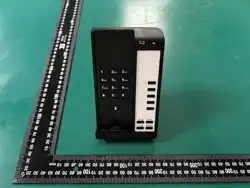
Telephone base unit
•
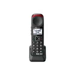
Mobile handset
•
Printed paper faceplate
•
Clear plastic faceplate cover
•
Power adapter
•
Handset battery
Optional items to be ordered separately:
•
Handset package: charging station, power
adapter, battery, handset
Features
•
Phone circuit can directly drive hands-free
•
Digital wireless/no interference technology
•
10 programmable speed dial keys for storing
up to 24 elements (digits and characters such
as *, #, Flash, and Pause)
•
Message Waiting Indicator and OneTouch
message retrieval key integrated into design
•
Handset auto-sync registration
•
Each base unit can register up to 4 additional
handsets
•
Handset battery low-voltage warning
•
Message high- and low-voltage detection
•
Message for reverse polarity Line
•
Extension detection function
•
6-ringer option (using the handset numeric
keypad 1–6)
Installation
CONNECTING THE POWER LINE CORD
Two line cords are provided: one RJ45 and one
RJ11
.
To install, simply plug one end of the RJ45 cord into
the modular jack at the top end of the base unit
and the other end into the RJ45 phone jack on the
power
adapt
or
.
Take the other
RJ11
line cord and
plug into the line jack on the power adaptor, then
plug the other end into the wall
.
Finish by plugging
the power adaptor into normal wall outlet
.
Be sure your power adaptor is specified for your
region of the world prior to plugging into the wall
socket
.
HANDSET BATTERY
CHARGING THE HANDSET BATTERY (ON BASE
AND CHARGING STATION)
The handset battery is a Li battery
.
This battery
requires a full charge prior to use to ensure long
life
.
To charge the battery, complete the
installation procedure by plugging the power
source into the wall outlet and the telephone
base or charging station
.
Install the battery per instructions, inserting
battery plug into receptacle
.
Place the battery in the opening in the handset,
press into place, then replace cover, and place
handset into base (face down) or charging station
(face down)
.
BATTERY LIFE—WHEN COMPLETELY
CHARGED
•
Talk time: 7.5 hours
•
Standby (handset off hook): 6 days
•
Charge for 24 hours to ensure a fully charged
battery
INSTALLING THE BATTERY INTO THE
HANDSET
1
.
Hold the handset and gently push up the
handset back shell
.
2 .
Remove the back, exposing the battery
compartment
.
3 .
Slide the battery plug into its receptacle,
matching up slot and opening on
receptacle
.
4
.
Do not force the battery
.
5
.
Press
on
back
end
of battery to
snap
into plac
e
.
6
.
Put the back shell of handset into slot,
then press down and snap into place
.

FACEPLATE
To install a faceplate, simply remove the plastic
overly (no tools required) and insert the paper
faceplate over the buttons
.
Then replace the
plastic
o
v
erla
y
.
Operation
VOLUME CONTROL
Ringer volume control: The ringer volume is
controlled via the
“
Volume
+/–”
k
e
y
.
There are five volume levels
.
When you have
reached the maximum or minimum sound level
there will be a warning beep
.
HANDSET VOLUME CONTROLS
The handset volume control increases the volume
of the handset
.
When the handset is off-hook or the Speaker key
engaged on speakerphones, press the Volume
Control keys to increase or decrease the volume
.
The handset volume control is a 5-step operation
.
All models are hearing aid compatible
.
ON-HOOK AND OFF-HOOK/PICK-UP
AND HANG-UP
Base unit: To get a dial tone with off-hook status,
press a line key or the Speaker key to pick up with
speak
er
.
To hang up or go on-hook, press the
Speaker key again to hang-up
.
Handset: Press ON/OFF key in the handset
faceplate to pickup or hang-up
.
HOLD
handset: Controls the “local hold” function
.
Each
press of the [Hold] key toggles the local hold mode
On or Off
.
An LED indicator located above the
[Hold] key displays the on-hold status
.
MUTE
The Mute key toggles the microphone Mute
function On and Off. The LED indicator above
the [Mute] key displays the On/Off status of the
Mute function
.
When Mute is on, the handset and
hands-free microphone audio are turned off
.
You
will be able to hear the party at the other end of
your call, but they will not be able to hear you
.
MESSAGE
1 .
The hidden 3-position switch marked
TYPE LR1 LR2 configures the message-
waiting lamp
.
2 .
For most applications the TYPE position
will work
.
This is the factory default
setting
.
Always try the TYPE position first:
If the message lamp blinks when a
message is in the mailbox, this confirms
that TYPE is the correct setting
.
3 .
For some PBX systems that provide
reverse polarity message signaling, it may
be necessary to move the switch to either
LR1 or LR2
.
The correct position of the
switch will cause the message lamp to be
on continuously when a message is in the
mailbox
.
PAGE
CALL THE HANDSET
Press the base unit’s Page key to call the handset
and the handset’s Message and On/Off indicator
lights flash
.
Press the Page key again (or any
key in the handset or place the handset into the
cradle) to end the page
.
REGISTERING A HANDSET
Auto-Sync Handset Registration
Place the handset into the base unit cradle and
make sure the charging leads make contact
.
The

Line will light up, and the base and the handset
will enter Registration mode
.
When the base and
the handset have successfully paired, the phone
will beep a Registration confirmation tone
.
SWITCH BETWEEN BASE AND HANDSET
If the handset is registered with the base unit, then
the handset and base can switch the call freely
.
To switch from the handset to the base, press the
Speaker key in the base unit
.
Press the ON/OFF
key in the handset to switch from base to handset
.
SWITCH BETWEEN HANDSETS
Every base unit can register up to 4 additional
handsets
.
If one of the handsets is picking up, any
one of the other handsets can pick up the call by
pressing the ON/OFF key
.
The ON/OFF indicator
of the other handsets will flash to display the
phone is in use
.
Programming
PROGRAM SPEED DIALS USING
SUBMERGED [STORE] AND [FLASH]
[Store] and [Flash] programming keys are located
under the faceplate and overlay; begin by lifting
up faceplate and overlay, by either a paperclip or
sharp pointer
.
STORING A NUMBER INTO MEMORY
KEYS—[STORE]
Each speed-dial location can store up to 24 digits
in tone mode
.
Note: Flash programmed into memory counts as
one digit when storing a number.
1
.
Press the
STORE
k
e
y
.
2
.
Enter the number to be stored using the
numeric dial pad
.
3
.
Press the
STORE
k
e
y
.
4
.
Press the desired memory location where
the number is to be stored
.
5 .
If additional numbers are to be stored,
repeat steps 3 through 5
.
6
.
Hang up the handset
.
PROGRAMMING FLASH TIMING
Flash timing options are 100 ms through 1000
ms, programmable in 100 ms increments
.
The
default Flash timing is 600 ms
.
1
.
Press the STORE key once
.
2. Program FLASH by pressing 1 for 100
ms, 2 for 200 ms, etc
.
3
.
Press
STORE
.
4
.
Press FLASH
.

In Case of Power Outage
The phone base will function without commercial
power (but the handset will not operate).
Ringer: When receiving a new call, the phone
base will ring, but not the handset
.
Pick up: Press the Line or Speaker key to pick up
.
Dial: Under off-hook status the loudspeaker and
microphone will receive sound and calls can be
placed using the dial pad
.
Hang-up: After talking, press the Speaker or Line
key to hang up
.
Note: Without commercial power, the base unit only
supports dialing and calling; the indicator lights will
fail to light; and Redial, Hold, Flash, Guest Service
Keys, and the handset will not operate.
Important Safety Instructions
When using your telephone equipment, basic
safety precautions should always be followed to
reduce the risk of fire, electric shock, and injury
to persons, including the following:
1
.
Read and understand all instructions
.
2
.
Follow all warnings and instructions
marked on the product
.
3
.
Unplug the product from the wall outlet
before cleaning
.
Do not use liquid cleaner
or aerosol cleaners
.
Use a damp cloth for
cleaning
.
4 .
Do not use this product near water—for
example, near a bathtub, wash bowl,
kitchen sink or laundry tub, in a wet
basement, or near a swimming pool
.
5
.
Do not place this product on an unstable
cart, stand, or table
.
The product may fall,
causing serious damage to the product
.
6 .
Slots and openings in the cabinet and the
back or bottom are provided for
ventilation, to protect it from overheating
.
These openings must not be blocked or
covered
.
The openings should never be
blocked by placing the product on the bed,
sofa, rug, or any other similar surface
.
This product should never be place near
or over a radiator or heat
r
egis
t
er
.
This
product should not be placed in a built-in
installation unless proper ventilation is
provided
.
7 .
Never push objects of any kind into this
product through cabinet slots as they may
touch dangerous voltage points or short
out parts that could result in a risk of fire
or electric shock
.
Never spill liquid of any
kind on the product
.
8 .
To reduce the risk of electric shock do
not disassemble this product
.
Take it to a
qualified service facility if service or repair
work is required
.
Opening or removing
covers may expose you to dangerous
voltages or other risks
.
Incorrect
reassembly can cause electric shock when
the appliance is subsequently used
.
9 .
Unplug this product from the wall outlet
and refer servicing to qualified service
personnel under the following conditions:
– When the power supply cord or plug is
damaged or frayed
.
– If liquid has been spilled into the
product
.
– If the product has been exposed to rain
or water
.
– If the product does not operate normally
by following the operating instructions
.
Adjust only those controls that are
covered by the operating instructions, as
improper adjustment of other controls
may result in damage and may require
extensive work by a qualified technician
to restore the product to normal
operation
.
– If the product has been dropped or the
cabinet has been damaged
.
– If the product exhibits a distinct change
in performance
.

10 .
Avoid using a telephone (other than a
cordless type) during an electrical storm
.
There may be a remote risk of electric
shock from lightning
.
11 .
Do not use the telephone to report a gas
leak in the vicinity of the leak
.
PLEASE SAVE THESE INSTRUCTIONS.
FCC Caution:
Any Changes or modifications not expressly
approved by the party responsible for compliance
could void the user's authority to operate the
equipment.
This device complies with part 15 of the FCC
Rules. Operation is subject to the following two
conditions: (1) This device may not cause
harmful interference, and (2) this device must
accept any interference received, including
interference that may cause undesired
operation.
Privacy of communications may not be ensured
when using this phone.
IMPORTANT NOTE:
Note: This equipment has been tested and found
to comply with the limits for a Class B digital
device, pursuant to part 15 of the FCC Rules.
These limits are designed to provide reasonable
protection against harmful interference in a
residential installation. This equipment generates,
uses and can radiate radio frequency energy and,
if not installed and used in accordance with the
instructions, may cause harmful interference to
radio communications. However, there is no
guarantee that interference will not occur in a
particular installation. If this equipment does cause
harmful interference to radio or television reception,
which can be determined by turning the equipment
off and on, the user is encouraged to try to correct
the interference by one or more of the following
measures:
—Reorient or relocate the receiving antenna.
—Increase the separation between the equipment
and receiver.
—Connect the equipment into an outlet on a circuit
different from that to which the receiver is
connected.
—Consult the dealer or an experienced radio/TV
technician for help.
FCC Radiation Exposure Statement:
This base complies with FCC radiation
exposure limits set forth for an uncontrolled
environment. This base should be installed
and operated with minimum distance 20cm
between the radiator& your body.
The handset has been tested and comply
with FCC SAR limits.
1. This equipment complies with Part 68 of the
FCC rules and the requirements adopted by the
ACTA. On the bottom of this equipment is a
label that contains, among other information, a
product identifier in the format
US:AAAEQ##TXXXX. If requested, this number
must be provided to the telephone company.
2. A plug and jack used to connect this equipment
to the premises wiring and telephone network
must comply with the applicable FCC Part 68
rules and requirements adopted by the ACTA. A
compliant telephone cord and modular plug is
provided with this product. It is designed to be
connected to a compatible modular jack that is
also compliant. See installation instructions for
details.
3. If this equipment [US: 2N3W405AV103] causes
harm to the telephone network, the telephone
company will notify you in advance that
temporary discontinuance of service may be
required. But if advance notice isn't practical,
the telephone company will notify the customer
as soon as possible. Also, you will be advised
of your right to file a complaint with the FCC if
you believe it is necessary.
4. The telephone company may make changes in
its facilities, equipment, operations or
procedures that could affect the operation of the
equipment. If this happens the telephone
company will provide advance notice in order
for you to make necessary modifications to
maintain uninterrupted service.
5. If trouble is experienced with this equipment
[US: 2N3W405AV103], for repair or warranty
information, Service can be facilitated through
our office at:
U.S. Agent Company name: Cetis, Inc.
Address: 4975 N. 30th Street Colorado Springs

CO, 80919 USA
Tel: +1 719 638 8821
Fax:N/A
If the equipment is causing harm to the
telephone network, the telephone company
may request that you disconnect the equipment
until the problem is resolved.
6. Please follow instructions for repairing if any
(e.g. battery replacement section); otherwise
do not alternate or repair any parts of device
except specified. For repair procedures, follow
the instructions outlined under the limited
warranty.
7. Connection to party line service is subject to
state tariffs. Contact the state public utility
commission, public service commission or
corporation commission for information.
8. If your home has specially wired alarm
equipment connected to the telephone line,
ensure the installation of this [W4] does not
disable your alarm equipment. If you have
questions about what will disable alarm
equipment, consult your telephone company or
a qualified installer.
9. If the telephone company requests information
on what equipment is connected to their lines,
inform them of:
a) The ringer equivalence number [0.5A]
b) The USOC jack required [RJ11C]
c) Facility Interface Codes (“FIC”) [N/A]
d) Service Order Codes (“SOC”) [N/A]
e) The FCC Registration Number [US:
2N3W405AV103]
10. The REN is used to determine the number of
devices that may be connected to a telephone
line. Excessive RENs on a telephone line may
result in the devices not ringing in response to
an incoming call. In most but not all areas, the
sum of RENs should not exceed five (5.0). To
be certain of the number of devices that may
be connected to a line, as determined by the
total RENs, contact the local telephone
company. The REN for this product is part of
the product identifier that has the format
US:AAAEQ##TXXXX. The digits represented
by ## are the REN without a decimal point. For
this product the FCC Registration number is
[US: 2N3W405AV103] indicates the REN
would be 0.5A.
11. We suggest the customers use a surge
arrestor to protect the device.