
1. Product Introduction
Dear user, thank you for using Thunderbol t Thunder Wir eless
Image Transmitter.
Thun der bo lt is a wir e l ess vide o tr an sm is s io n sy ste m
inde pe nd ent ly deve lop ed by Bes TV.
One of the features supports 1080p/60Hz resolution with backward
compatibility for multiple resolutions, enabling seamless implementation.
400-meter long-distance wireless transmission with automatic
selection of optimal configurations for open spaces and
Optimal frequency bandwidth for multi-disruption environments.
With latency as low as 70 milliseconds, the HDCP protocol prevents
interference and is suitable for complex environments. Supports
Type-C interface and NP-F battery power, enables real-time audio-
video synchronization transmission, and features dual HDMI ports
for plug-and-play functionality.
Supports high-definition output, enabling seaml ess
monitoring for di rectors/cameras and live sc ene
transmission.
2. Product Features
S upports HD 1080p/60 and
backward compatibility with
H.264 video codec
S uppo rts auto mat ic fre que nc y ho pp ing
(auto ma t ica l ly detec ts envi ro n me n tal
inte rf er enc e an d sw it ch es to clea n ch an nel s) and
HDCP proto co l
T he tra nsm itter supports HDMI
input and HDMI loop output, whi l e
the receiver supports dual HDMI
outputs.
L ow latency 70ms
O perating frequency bands: 5150MHz–5250MHz,
5250MHz –5350MHz, 5470MHz–5725MHz, 5725MHz–
5850MHz, with a bandwidth of 20MHz and an
unobstructed transmission range of 400 meters.
S upports battery power from Type C and NP-F batteries
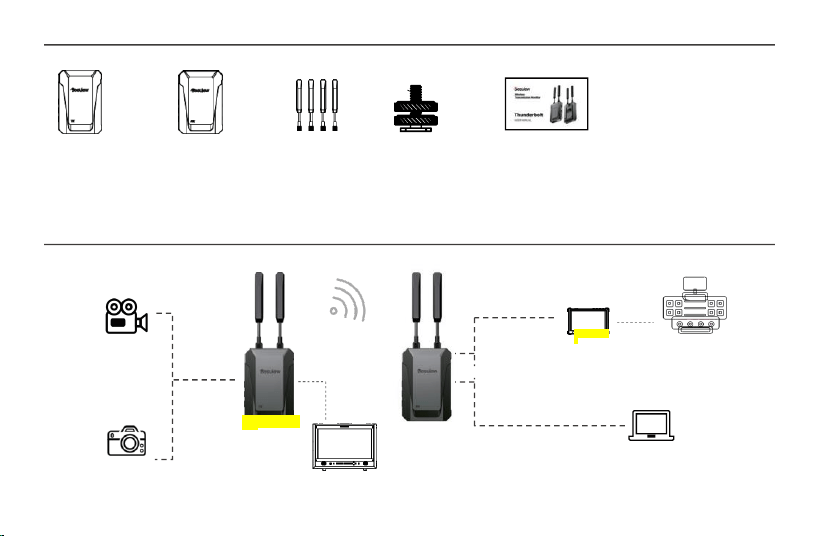
3. Packing List
Transmitter TX x 1, Receiver RX x 1, Antenna x 4, Cold Boot x 1, Instruction Manual/Certificate of Conformity x 1 Transmitter TX x 1,
Receiver RX x 1, Antenna x 4, Cold Boot x 1, Instruction Manual/Certificate of Conformity x 1 Transmitter TX x 1, Receiver RX x 1,
Antenna x 4, Cold Boot x 1, Instruction Manual/Certificate of Conformity x 1 Transmitter TX x 1, Receiver RX x 1, Antenna x 4, Cold
Boot x 1, Instruction Manual/Certificate of Conformity x 1 Transmitter TX x 1, Receiver RX x 1, Antenna x 4, Cold Boot x 1,
Instruction Manual/Certificate of Conformity x 1
4. Application Examples
cam e ra
HDMI output
400m
Dire c t o r ' s c o n so l e
HDMI import
receiver (RX)
HDMI output
Co m p u te r vi d eo re s o u r c e s
came r a
moni t or
moni t o
r
transmitter (T
X)
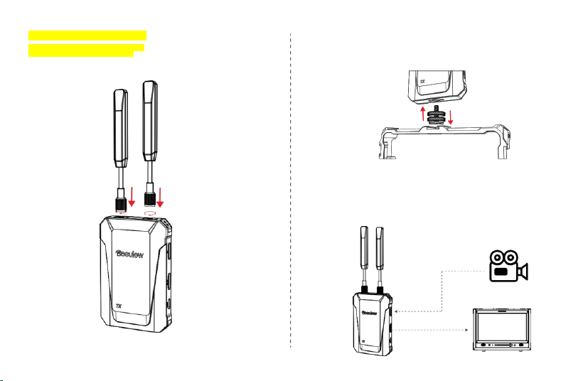
5.3 Mounting the image transmission device
on other equipment
Mount Thunderbolt on your camera or other equipment using a snail mount or a specialized tool like a monster hand.
5.4 Connection Lines
Connect the video transmission system to cameras and monitoring devices using
HDMI cables based on practical application requirements.
HDMIIN
HDMIOUT
5.2 Antenna Installation
Install the antenna at the top of the image
transmission as shown in the diagram.
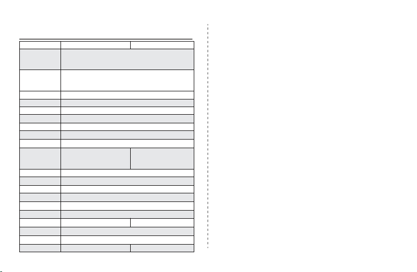
6. Technical Specifications
ejector TX
acceptor RX
Operating
frequency range
5150MHz~5250MHz
5250MHz ~5350MHz
5470MHz ~5725MHz
5725MHz~5850MHz
Video format
1080P60/1080P59.94/1080P30/1080P29.97/1080P25/1080P24
1080I60/1080I50/720P60/720P50/576P60
576I60/480P60/480I60
Audio format
PCM
HDMI protocol
HDMI1.3
HDCP protocol
HDCP 1.4
transmission
delay
70ms
video coding
H.264
transmission
distance
400M (barrier-free, interference-free)
Antenna
configuration
1T2R
Product interface
HDMI in put / HDMI
ring output
Type-C
HDMI ou tput
*2Type-C
Product buttons
Switch button, pairing button, battery level indicator button
Status indicator
light
Switches, network connections
working power
supply
Type_C
(
5V_2A
)
/ NP-F
(
6.4V-8.4V
)
Heat dissipation
method
/
productsize
104×70×16mm
Product power
consumption
2.5W
2W
working
temperature
-10
°
C~45
°
C
Storage
temperature
-40°C~60°C
weight
197g
197g
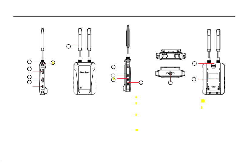
5. Rapid application
5.1 Interface Button Labeling
Note: The RX end lacks an HDMI inputinterface,whileall other interfacesareidentical to those on theTX end.
6
1
12
7
3
8
4
13
5
4 HDMI ring output ports
Transmitter: Route HDMI input signals to other
devices Receiver: HDMI output, deliver
received video signals
5 Type-C power port
supports 5V-2A
power supply
6 Signal Antenna
2T2R external 3dBi
2
10
11
battery status
Switch button
Short press for about 1 second to
power on, and long press for 3
seconds to power off.
Signal connection button
Long press for three seconds to
enter pairing mode
Battery level button
Press and hold for 1 second to
display battery level
1 Connectionstatus
indicator lightRed
light: Modelnot
connectedGreenlight:
Signalconnected
2 Power indicator light
Redlight: Connected to
power.Greenlight: The
machine is on.
3 HDMI input ports
HDMI port for video source
connection
11 1/4" threaded joint
12 Battery Release
Button
13 NP-F Series Battery
Backplate
10
7
8
9
9
harmful interference to radio communications. However, there is no guarantee that
interference will not occur in a particular installation. lf this equipment does cause
harmful interference to radio or television reception, which can be determined by
turning the equipment off and on, the user is encouraged to try to correct the
interference by one or more of the following measures:
-Reorient or relocate the receiving antenna.
Increase the separation between the equipment and receiver.
-Connect the equipment into an outlet on a circuit different from that to which
the receiver is connected.
-Consult the dealer or an experienced radio/TV technician for help.
Radiation Exposure Statement
This device complies with FCC radiation exposure limits set forth for an
uncontrolled environment and it also complies with Part 15 of the FCC RF Rules.T
his equipment should be installed and operated with a minimum distance 20cm b
etween the device and your body.
This device complies with part 15 of the FCC Rules. Operation is subject to the following two conditions: (1) This device may not cause harmful
interference, and (2) this device must accept any interference received, including interference that may cause undesired
FCC Statement
This equipment has been tested and found to comply with the limits for a Class B
digital device, pursuant to Part 15 of the FCC Rules.These limits are designed to provide reasonable protection against harmful interference in a re
sidential installation.This equipment generates, uses and can radiate radio frequency energy and,
if not installed and used in accordance with the instruc tions, may cause
operation.
Changes or modifications not expressly approved by the party responsible for compliance could void the user’s authority to operate the equipment.