www.follettice.com
01473883R01
Installation, Operation and Service Manual
Undercounter and Freestanding
R290 Integrated Icemaker
Following installation, please forward this manual
to the appropriate operations person.
Follett Europe Polska Sp. z o.o.
Mokry Dwór 26 c • 83-021 Wiślina, Poland
+48 (58) 785-6140 • Fax +48 (58) 785-6159
www.folletteurope.com
801 Church Lane • Easton, PA 18040, USA
Toll free (877) 612-5086 • +1 (610) 252-7301
www.follettice.com
2 Integrated Icemaker R290
Contents
Welcome ..................................................................................... 3
Before You Begin ............................................................................ 3
Important Safety Information ..................................................................... 4
Specications ................................................................................. 5
Detailed Drawing ............................................................................... 7
Installation .................................................................................... 8
Start-Up Procedure ............................................................................11
Periodic Cleaning and Sanitizing ................................................................ 12
Service ...................................................................................... 16
Accessing Internal Components ................................................................. 17
Water System ................................................................................. 18
Electrical System .............................................................................. 20
Starting Procedure ............................................................................ 22
Wiring Diagram ............................................................................... 31
Compressor Data ............................................................................. 32
Mechanical System ............................................................................ 33
Refrigeration System .......................................................................... 35
Troubleshooting .............................................................................. 37
Replacement Parts ............................................................................ 38
Risk of re or explosion. Flammable refrigerant used. Follow handling instruction carefully. To
be repaired only by trained service Personnel.
Do not puncture Refrigerant Tubing. Do not use this product with ammable gases or ammable
solvents.
Do not store ammable gases, ammable liquids or ammable solids in these units. Do not use
FLAME to check for gas leak.
Do not under any circumstances try to modify or repair valves, regulator, connectors, controls or
any other appliance. Doing so creates the risk of a gas leak.
Keep ventilaton openings clear of obstruction.
Do not damage the refrigerant circuit.
Connect to potable water supply only.
Integrated Icemaker R290 3
Welcome
Follett equipment enjoys a well-deserved reputation for excellent performance, long-term reliability, and
outstanding after-the-sale support. To ensure that this product delivers that same degree of service, we ask that
you take a moment to review this manual before beginning the installation. Should you have any questions or
require technical help at any point, please call our technical service group at +48 58 785 61 40 for European
market, and +1 877-612-5086 for US market.
Before You Begin
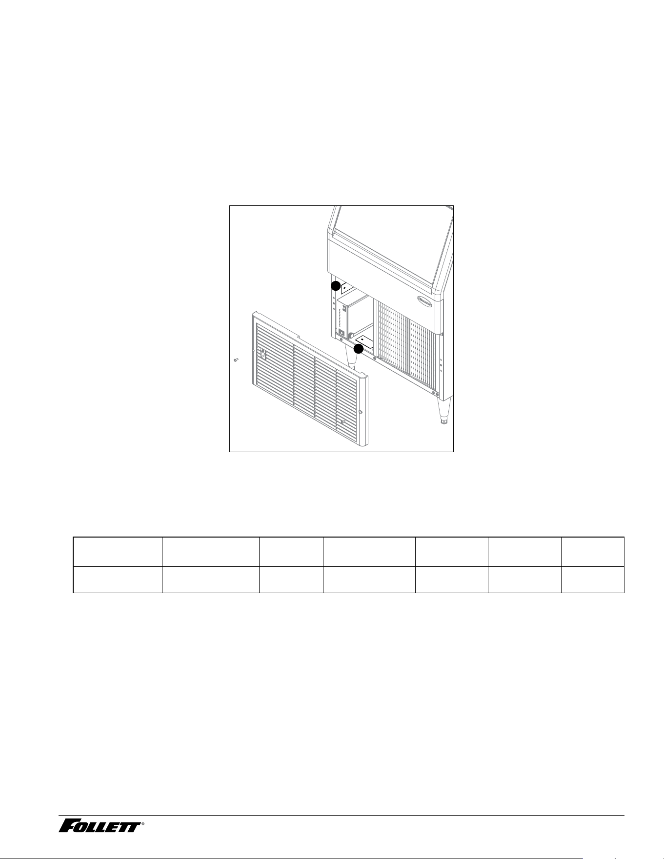
After uncrating and removing all packing material, inspect the equipment for concealed shipping damage. If
damage is found, immediately notify the shipper and contact Follett Corporation so that we can help in the ling
of a claim, if necessary. If needed, the serial number of your dispenser can be found by removing the grill and
locating the serial number label (1) on the bin and on the bottom of the main frame (2).
1
2
Check your paperwork to verify that you received the correct dispenser. Follett conguration numbers are
designed to provide information about the type of dispenser you are receiving. The following is an explanation of
the different model numbers.
U F C 4 14 A 80
Product
Type
Ice Type Voltage Icemaker
Capacity
Refrigerant
Type
Condenser Bin
Capacity
U Undercounter F Flake
M Micro Chewblet
D 115/60
E 230/50
4 Up to 425 lbs 14 R290 A Air cooled 80 80 lbs.
4 Integrated Icemaker R290
Important Safety Information
CAUTION!
§ For indoor use only. Designed for commercial use. Follett is not able to provide in-house services for residential
installations.
§ This appliance should be permanently connected by a qualied person in accordance with application codes.
§ If the supply cord is damaged, it must be replaced by the manufacturer, its service agent or similarly qualied
persons in order to avoid a hazard.
§ Connect to potable water supply only.
§ This appliance can be used by children aged 8 years and above and persons with reduced physical, sensory,
or mental capabilities, or lack of experience and knowledge if they have been given supervision or instruction
concerning use of the appliance in a safe way and understand the hazards involved. Children should be
supervised to ensure that they do not play with the appliance.
§ Children should not be allowed to perform any maintenance of this appliance.
§ Do not store explosive substances such as aerosol cans with a ammable propellant inside the bin!
§ Warranty does not cover exterior or outside installations.
§ Moving parts. Do not operate with front cover removed.
§ Hot parts. Do not operate with cover removed.
§ To reduce risk of shock, disconnect power before servicing.
§ Follett recommends water ltration system. Contact Follett for more information.
§ Most icemaker cleaners contain citric or phosphoric acid, which can cause skin irritation. Read caution label on
product and follow instructions carefully.
§ Ice is slippery. Maintain counters and oors around dispenser in a clean and ice-free condition.
§ Ice is food. Follow recommended cleaning instructions to maintain cleanliness of delivered ice.
§ To avoid potential contamination do not use the surface of the unit as a worktop.
Integrated Icemaker R290 5
Specications
Electrical
§ Power supply:
— 230 V, 50/60 Hz, 1 phase, maximum machine amperage 3.8A, maximum fuse 10A (UME/UMC/UFE/UFC
models)
— 115 V, 60 Hz, 1 phase, maximum machine amperage 7.0A, maximum fuse 15A (UMD/UFD models)
§ Connect to dedicated circuit.
§ Must be grounded (requires 3-prong outlet). Do not remove ground.
§ Replacement cord instructions, if the supply cord is damaged, it must be replaced by a special cord or assembly
available from the manufacturer or its service agent.
Plumbing
§ 3/8" OD push-in water inlet
§ 3/4" MPT drain
Notes:
§ 3/4" drain line must slope 1/4" per foot (6 mm per 30,4 cm run). Maximum drain line run is 6 ft (1.8 m) for units
without 6" legs.
§ Drain to be hard piped and insulated.
§ To prevent back ow, do not connect drains.
§ Water shut-off recommended within 5 ft (1,5 m), drain to be hard piped and insulated.
§ Follett recommends a Follett water lter system be installed in the ice machine inlet water line (standard capacity
#00130229, high capacity #00978957, carbonless high capacity #01050442).
Ambient
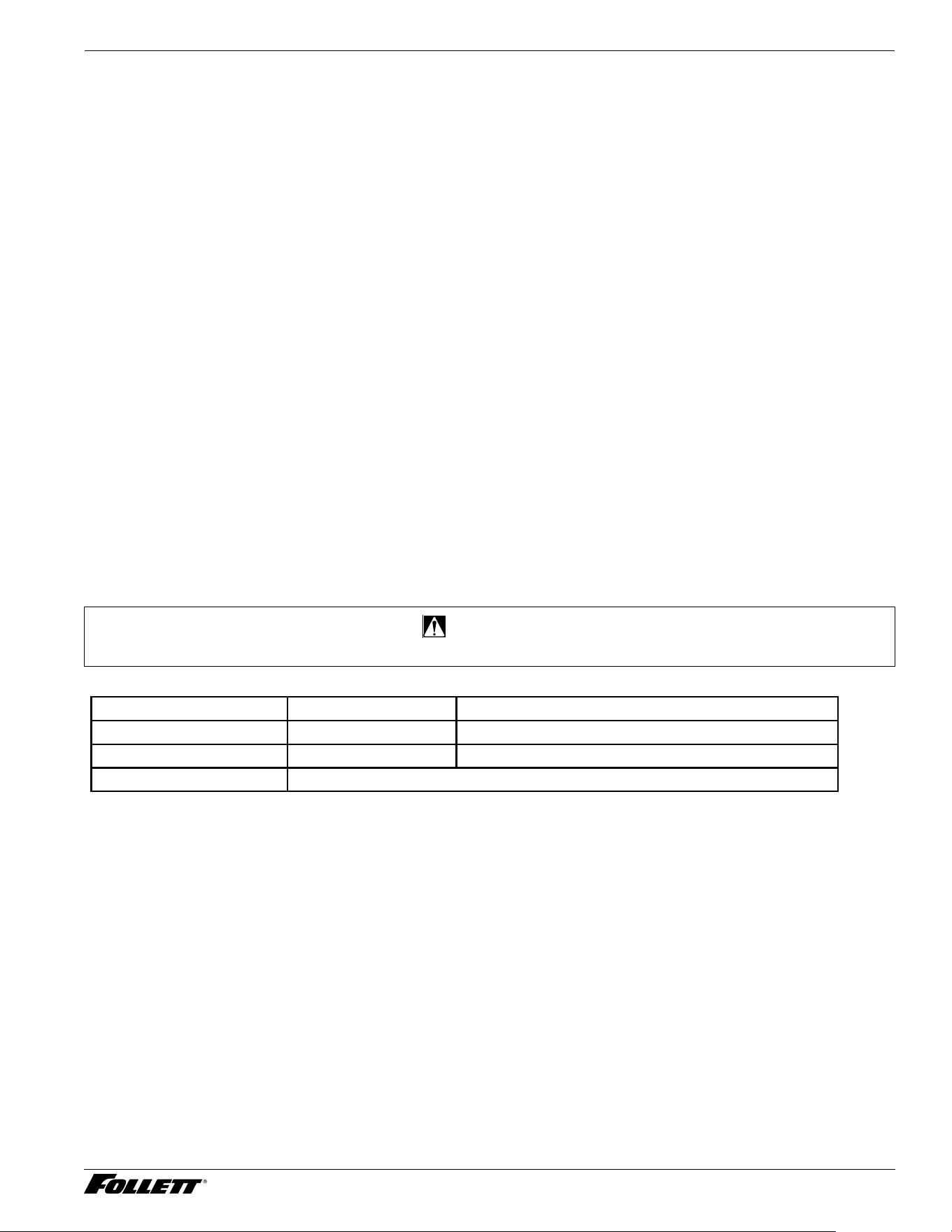
CAUTION!
§ This unit is for indoor use only.
Air temp* 100 F/38 C max. 50 F/10 C min. Best performance below 80 F (27 C)
Water temp
†
90 F/32 C max. 40 F/7 C min. Best performance below 70 F (21 C)
Water pressure 70 PSI/5 Bar max. 10 PSI/0.7 Bar min.
Relative humidity 55% at 78 F (25,5 C)
* Use outside of these limits is misuse and will void warranty.
†
Best performance is achieved between 80 F (27 C) and 50 F (10 C).
Heat Rejection
§ 5000 BTU/hr
6 Integrated Icemaker R290
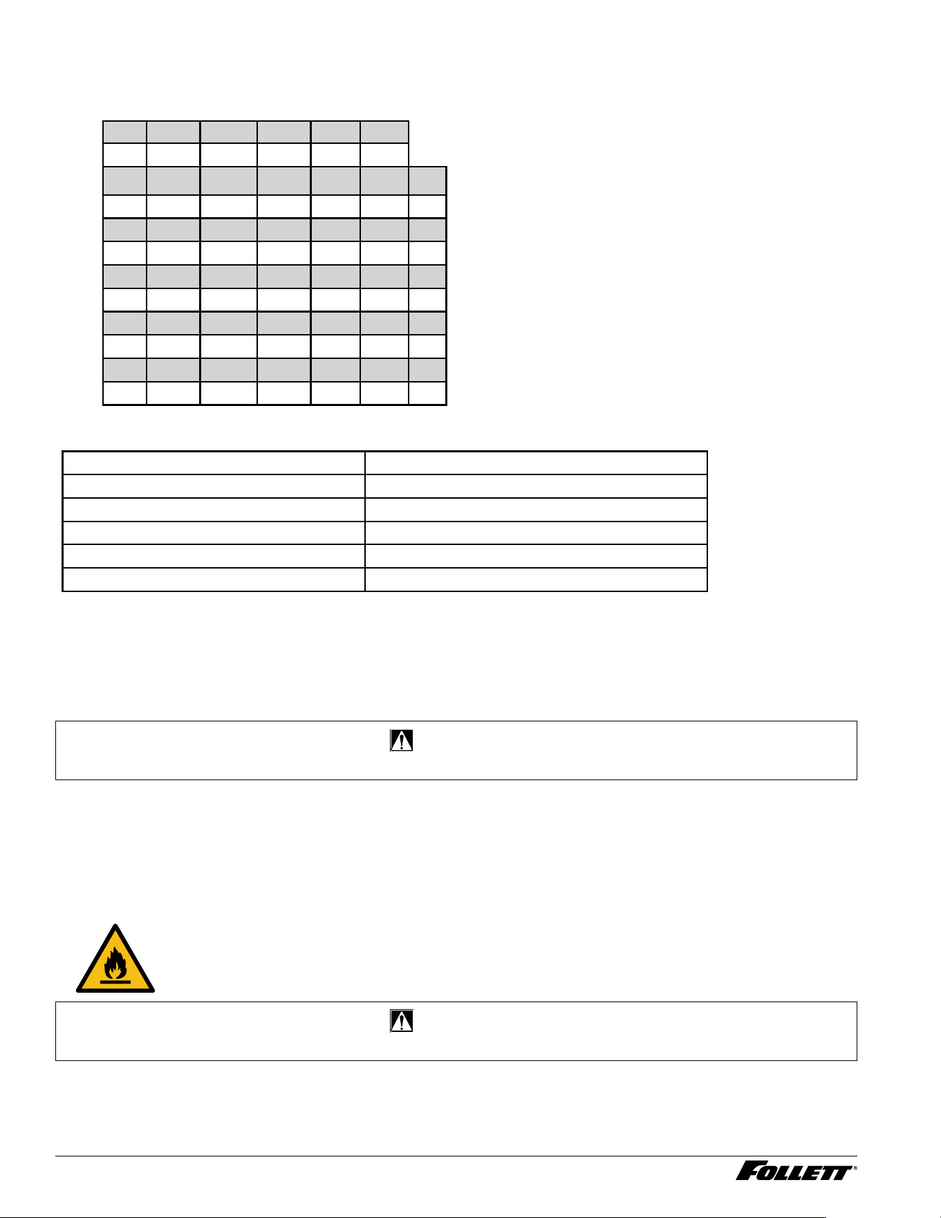
Ice Production Chart
Air-Cooled icemaker capacity/24hrs.
Ambient Air Temperature F/C
Inlet Water Temperature F/C
F 60 70 80 90 100
C 16 21 27 32 38
50 497 443 387 327 266 lb
10 226 201 176 148 121 kg
60 472 424 389 379 263 lb
16 219 193 173 146 120 kg
70 443 407 371 315 259 lb
21 201 185 169 143 118 kg
80 413 375 338 290 241 lb
27 188 171 154 132 109 kg
90 384 345 305 263 221 lb
32 176 157 138 120 100 kg
Dimensions
Width 23.43" (59,5 cm)
Depth 25.98" (66,0 cm)
Height 32.99" (83,8 cm)
Height with legs 38.90" (98,8 cm)
Unit shipping weight 185 lb (84 kg)
Unit net weight 154 lb (70 kg)
Clearances
§ This unit is a front-breathing device. No side and back clearances needed.
Water
CAUTION!
§ Connect to potable water supply only.
§ Not recommended for use with softened water
§ Ingress Protection (IP) rating: IPX0 (no protection)
§ Water pressure: 10–70 psi (69–483 kPa)
Refrigeration
Caution: Risk of re.
CAUTION!
§ Do not damage the refrigerant circuit. Refrigerant can cause personal injury and/or damage dispenser.
§ Refrigerant R290 – 99 g (3.49 oz.).
Integrated Icemaker R290 7
Detailed Drawing
26.0" (66 cm)
23.43" (59,5 cm)
5.9"
(15 cm)
33"
(83,8 cm)
5.8"
(14,7 cm)
2.1"
(5,4 cm)
6.4"
(16,3 cm)
2
1
3
2
1
3
3/8" OD push-in water inlet
3/4" MPT drain outlet
Power supply cable entry grommet
Power cord connection
0.2" (5 mm)
33.2"
(84,3 cm)
4
With 6" Legs
With Leveling Feet
4
8 Integrated Icemaker R290
Installation
CAUTION!
§ For indoor use only. Designed for commercial use. Follett is not able to provide in-house services for residential
installations.
§ Use caution when tipping the dispenser during leg installation. Do not lay unit on back or side. DO NOT
EXCEED 30° angle. Tipping more than 30° can result in compressor malfunction.
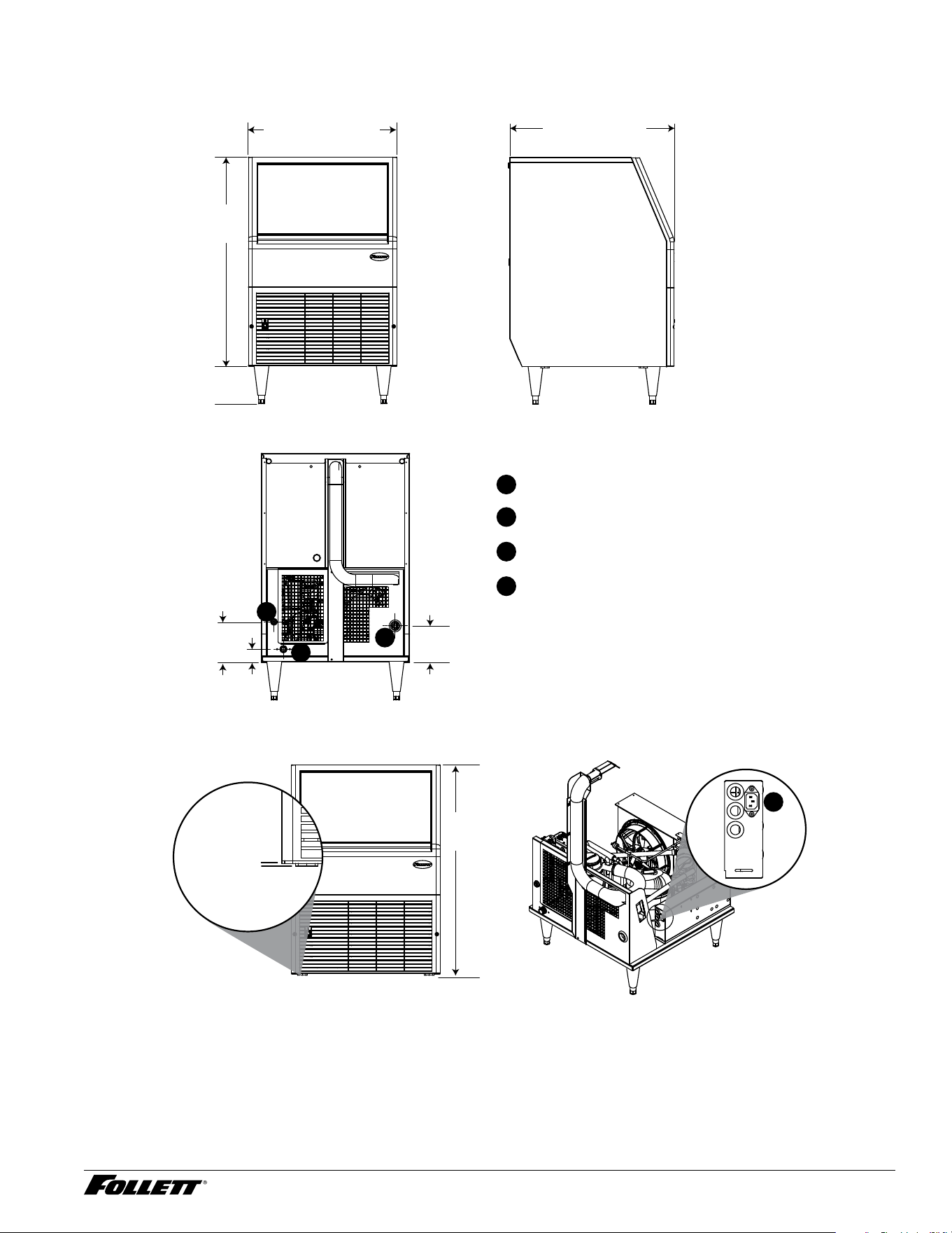
Uncrating Information
1. Carefully unpack and inspect the contents of
your Follett icemaker.
2. Unscrew all four bolts fastening the machine
to the skid.
3. Slide the unit to one side of the skid and
screw in supplied accessory leg set or
leveling feet according to your machine setup.
Fig. 1
Screw, hex
HD cap,
5/18-11 x 1-3/4
Fig. 2 - Leg Set (Freestanding) or Leveling Feet (Undercounter) Option
LEG SET
LEVELING
FEET
Integrated Icemaker R290 9
Undercounter Installation
Install icemaker section rst, to ease installation
procedure. Installation instructions for freestanding
model may be found on page 10.
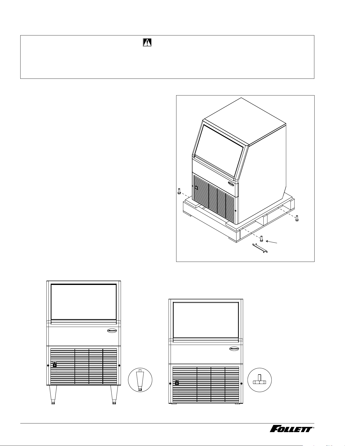
Bin portion must be removed after uncrating
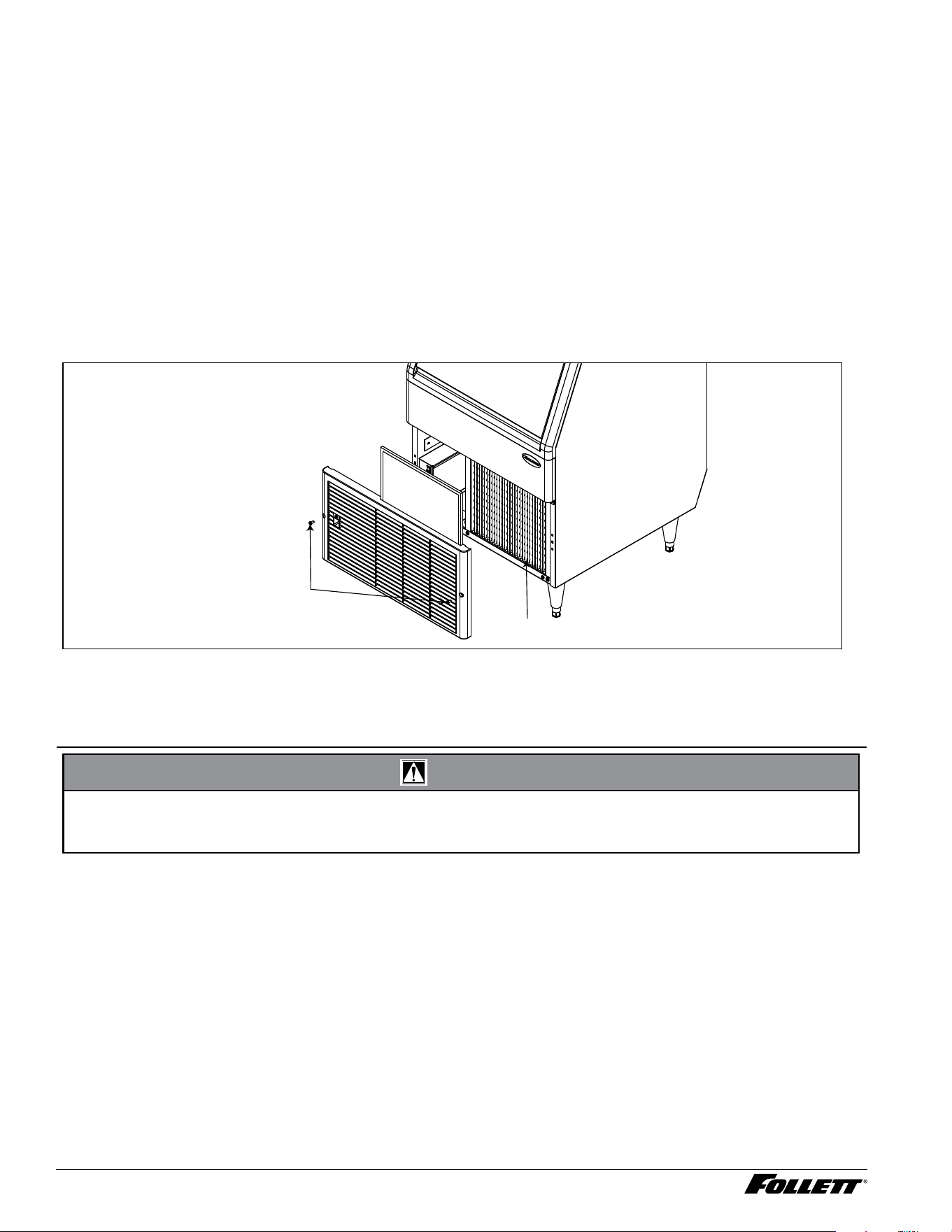
1. Remove the front grille (Fig. 3.1).
2. Remove two screws behind the grille
(Fig.3.2).
3. Remove the drain tube from the ice bin
(Fig.4).
4. Facing the unit, slide the bin out by pulling it
towards you.
Rough-in the electrical service and water line
§ Unit is provided with a 2.4 m IEC power cord.*
— UFC, UMC family (220 V/60Hz)
— UFE, UME family (230 V/50 Hz)
§ For 115/60Hz market the UFD, UMD family comes
with NEMA 5-15A grounded – complete power cord
with plug
§ Water: supply line (with shut-off valve) connects to
the dispenser’s (3/8" OD push-in water inlet)
Note: This appliance is intended to be permanently
connected to water main using 3/8" OD
tubing.
1. Connect water line and drain. Maximum drain
line run is 6 ft (1.8 m). Recommended routing
(Fig. 5) allows easy access to water for
cleaning and sanitizing procedure. Verify the
bin drain shut-off valve is open (Fig. 4).
2. Connect power supply.
3. Unit must be level to operate properly.
4. Install bin portion after all supplies are
connected.
5. Sanitize the dispenser prior to use (see
Cleaning and Sanitizing on page 11).
* Depending on the market, the user must install the proper
plug per local electrical code (plug not included.)
Fig. 3
ICE BIN
FRONT
GRILLE
SCREWS
ICEMAKER
THERMOSTAT
2
1
Fig. 4
STORAGE
BIN
DRAIN
TUBE
SHUT-OFF
VALVE
10 Integrated Icemaker R290
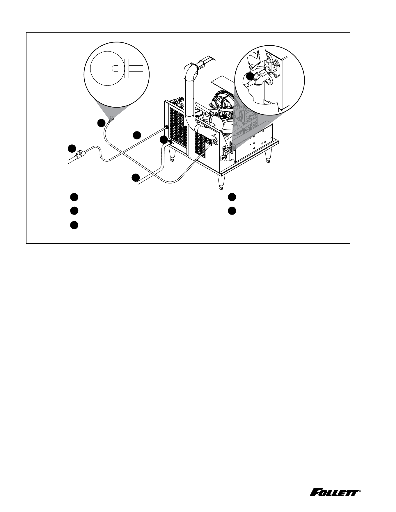
Fig. 5 - Undercounter
2
1
3
3/8" OD push-in water inlet
3/4" MPT drain outlet
Power supply cord: NEMA 5-15 for 115 V/60 Hz
(no plug for other voltages)
2
1
3
4
5
5
4
Water shut-off valve
Drain line (not supplied)
115 V/60 Hz
L2
L1
G
Maximum drain line run
is 6 ft (1.8 m).
3
Freestanding Installation
1. Rough-in the electrical service and water line
Unit is provided with a 2.4 m IEC power cord. Depending on the market, the user must install the proper plug
per local electrical code (plug not included.):
— UFC, UMC family (220 V/60 Hz)
— UFE, UME family (230 V/50 Hz)
§ For 115 V/60 Hz market the UFD, UMD family comes with NEMA 5-15A grounded – complete power cord
with plug.
§ Water: supply line (with shut-off valve) connects to the dispenser’s 3/8" OD push-in water inlet.
Note: This appliance is intended to be permanently connected to water main using 3/8" OD tubing.
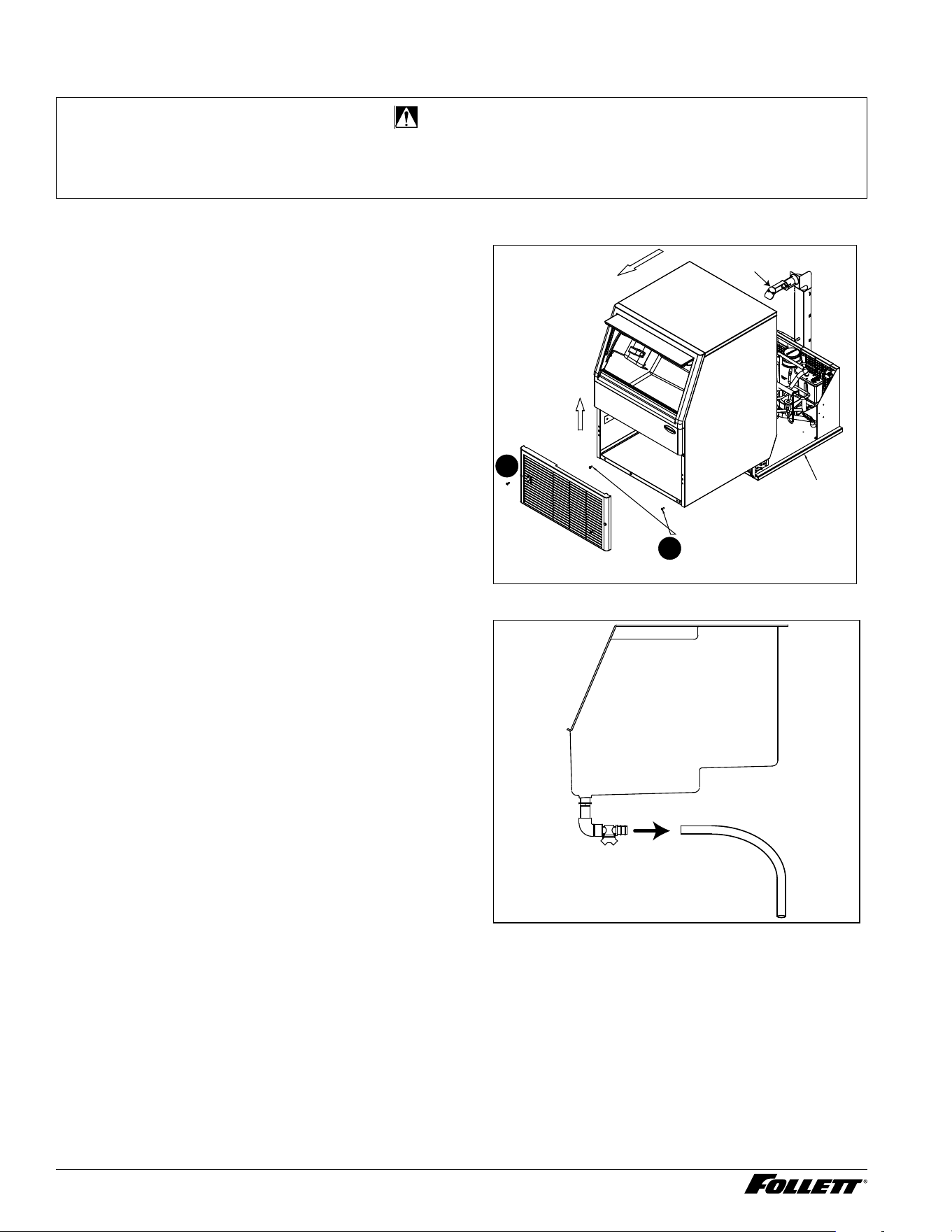
2. Connect water line and drain. Recommended routing (Fig. 6) allows easy access to water for cleaning
and sanitizing procedure. Ensure that the water drain valve is open (Fig. 4).
3. Connect power supply.
4. Ensure that the unit is level. Unit must be level to operate properly.
5. Sanitize the dispenser prior to use (see Cleaning and Sanitizing on page 12).
Integrated Icemaker R290 11
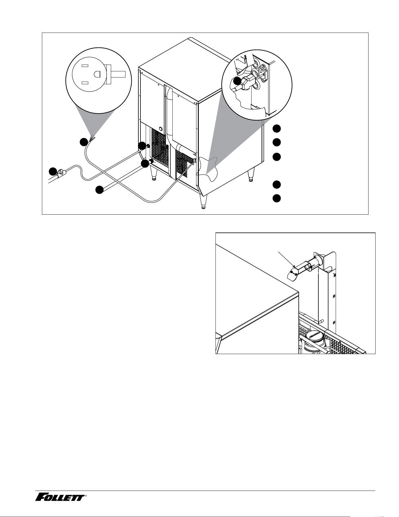
Fig. 6 - Freestanding
2
1
3
4
5
2
1
3
3/8" OD push-in water inlet
3/4" MPT drain outlet
Power supply cord:
NEMA 5-15 for 115 V/60 Hz
(no plug for other voltages)
5
4
Water shut-off valve
Drain line (not supplied)
115 V/60 Hz
L2
L1
G
3
Start-Up Procedure
Before turning power on
1. Clean and sanitize ice bin in accordance with
cleaning procedure.
2. Turn water to icemaker ON.
After turning power on
1. Turn ON the machine with on/off switch and
conrm that gearmotor, compressor and fan
motor start.
2. Check that ice begins to enter bin within
approximately 5 minutes.
3. After making ice for 5 minutes, put ice against
ice level thermostat tube (Fig. 7) and check
that icemaker shuts down.
4. Warm the ice level thermostat tube with your
ngers and check that icemaker restarts in
approximately 20minutes (bin must be calling
for ice).
Fig. 7
THERMOSTAT
12 Integrated Icemaker R290
Periodic Cleaning and Sanitizing
Periodic cleaning/descaling and sanitizing of Follett’s ice and water dispenser and icemaker system is required to
ensure peak performance and delivery of clean, sanitary ice. The recommended cleaning procedures that follow
should be performed at least as frequently as recommended and more often if environmental conditions dictate.
Cleaning of the condenser can usually be performed by facility personnel. Cleaning/descaling and sanitizing
of the icemaker system should be performed by your facility’s trained maintenance staff or a Follett authorized
service agent. Regardless of who performs the cleaning, it is the operator’s responsibility to see that this cleaning
is performed according to the schedule below. Service problems resulting from lack of preventive maintenance will
not be covered under the Follett warranty.
Condenser
Unit is supplied with condenser lter (Fig. 8). At least once per month use a vacuum cleaner or stiff brush to clean
condenser lter and evaporator coils of lint and debris to ensure optimal performance. To access condenser lter
remove plastic front cover grille.
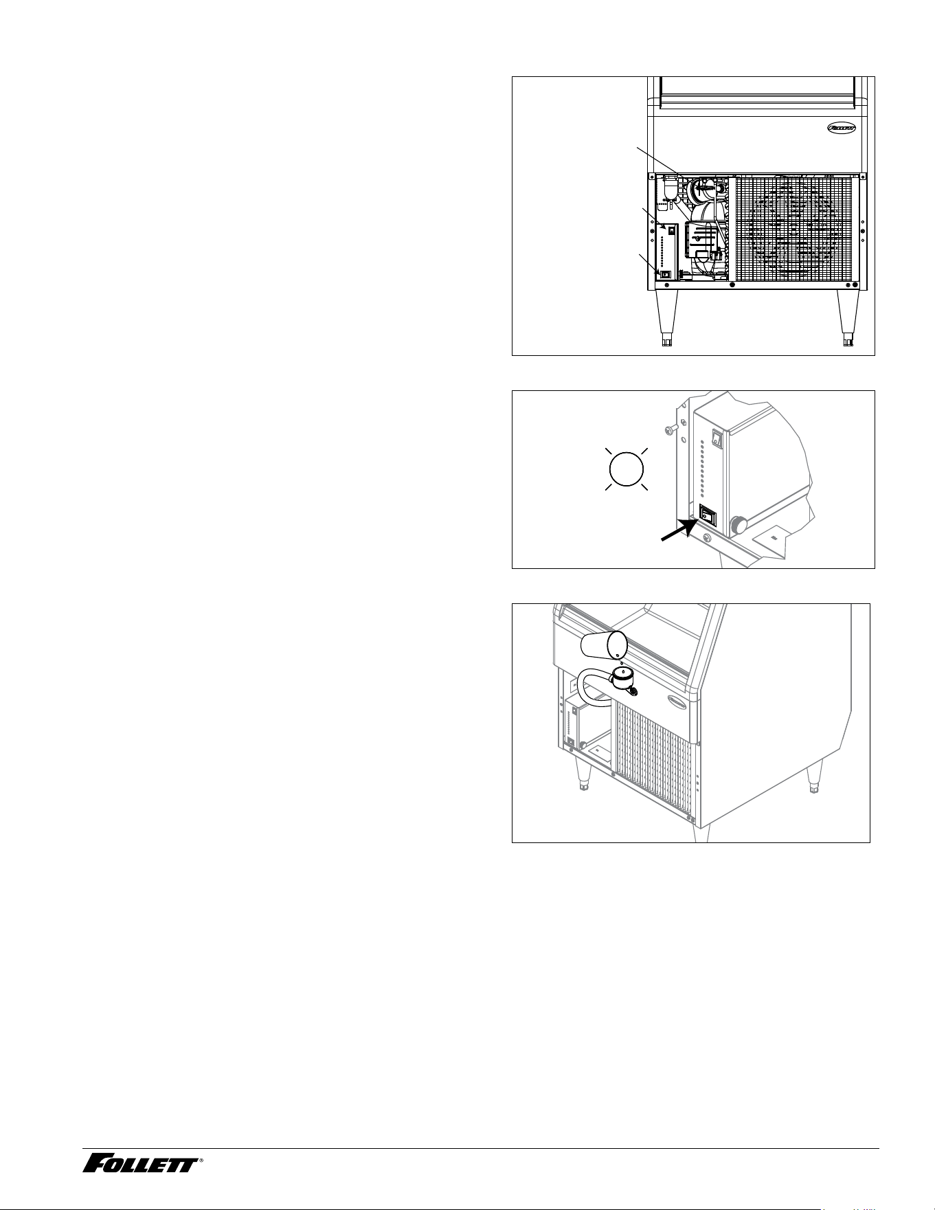
Fig. 8
CONDENSER
SCREWS
FRONT GRILLE
FILTER
Cleaning/Descaling and Sanitizing
Cleaning and sanitizing should be performed at least every 6 months (more often if local water conditions dictate).
For initial startup, only sanitizing is required.
CAUTION!
§ Wear rubber gloves and safety goggles (or face shield) when handling SafeCLEAN Plus solution.
§ Use only Follett approved cleaners.
§ Do not use solvents, abrasive cleaners, metal scrapers or sharp objects to clean any part of the dispenser.
Required Supplies
Cleaning Tool Checklist
§ (1) 1.5 gallon (or larger) plastic bucket
§ (2) clean cloths
§ Sanitary gloves
§ Safety glasses
§ SafeCLEAN™ Plus ice machine cleaner
§ (2) SaniSponge™ (PN 00131524 - single sponge)
SafeCLEAN Plus Solution: Follow the directions on the SafeCLEAN Plus packaging to mix 1 gal. (3.8 L) of
Follett SafeCLEAN Plus solution. Use 100 F (38 C) water.
Integrated Icemaker R290 13
Cleaning
1. Remove front grille to access internal
components (Fig. 9).
2. Press clean switch on the main control box.
The MAINTENANCE light will turn on and the
machine will drain. Wait for the LOW WATER
light to turn on (Fig. 10).
3. Remove lid from cleaning cup (Fig. 11) and ll
(about 1 quart) until
SafeCLEAN Plus
solution
completely lls the reservoir. Place lid back on
cup.
4. Soak one SaniSponge in remaining
SafeCLEAN Plus
solution.
5. CLEANER FULL light will turn on (Fig.12)
and machine will start cleaning cycle
then rinse three times; this process takes
approximately 15 minutes.
6. When machine is nished cleaning, the
MAINTENANCE light will turn off.
7. Remove any remaining cleaner from tube and
cleaning cup.
Note: The next steps must be completed before
machine ushes and starts producing ice!
Fig. 9
CLEANING CUP
ON/OFF SWITCH
CLEAN SWITCH
Fig. 10
LO WATER
Fig. 11
14 Integrated Icemaker R290
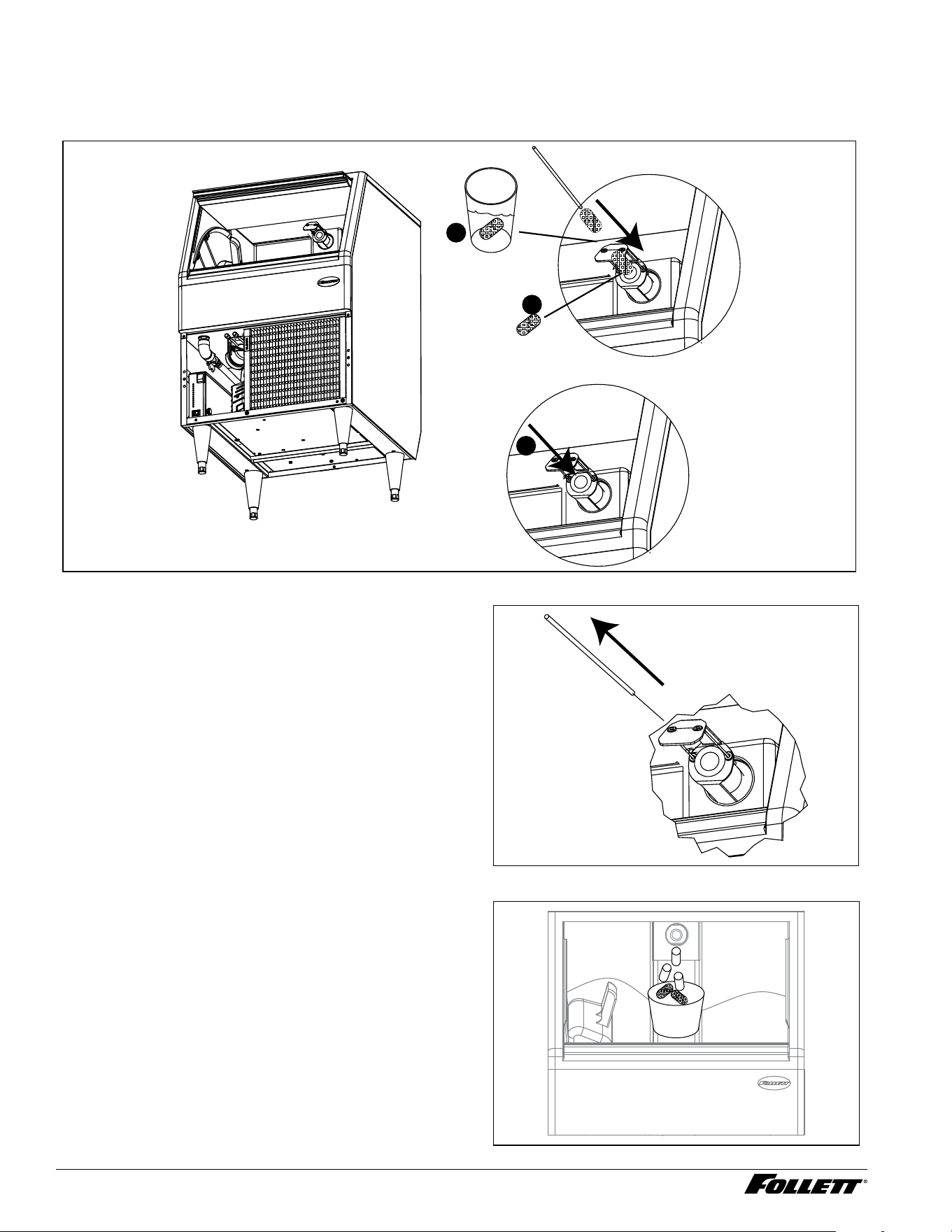
8. Using disposable food service grade gloves, insert one dry Sani-Sponge™ (Fig.13.1). Next, insert one
Sani-Sponge soaked in
SafeCLEAN Plus
solution (Fig.12.2). Push both of the Sani-Sponges down ice
transport tube (ice chute outlet) with supplied pusher tube (Fig.12.3).
Fig. 12
3
2
1
9. Remove and discard pusher tube (Fig.13).
10. The MAINTENANCE light will turn off and
machine will start producing the ice. Ice
pushes Sani-Sponges through the tube.
11. Place a sanitary (2 gallon or larger) container
in bin to collect Sani-Sponges and ice for
10minutes. Collect 5.5 lbs (3 kg) of ice from
unit. Discard ice and Sani-Sponges (Fig. 14).
Cleaning bin before use and ongoing bin
maintenance
Interior of bin must be cleaned and sanitized prior to
use and should be cleaned on a routine basis during
use.
Interior bin care
Bin is equipped with polyethylene liner and stainless
steel elements that should be cleaned and sanitized
periodically with products suitable for use in a food
zone. While cleaning and sanitizing the thermostat
capillary tube bracket area, use products that are
non-aggressive to such materials. After cleaning and
sanitizing, rinse thoroughly with potable water.
Fig. 13
Fig. 14
Integrated Icemaker R290 15
Service
CAUTION!
§ No service or maintenance should be performed until the technician has thoroughly read this service manual.
Except for routine cleaning and sanitizing, only qualied technicians should attempt to service or maintain this
equipment.
Overview
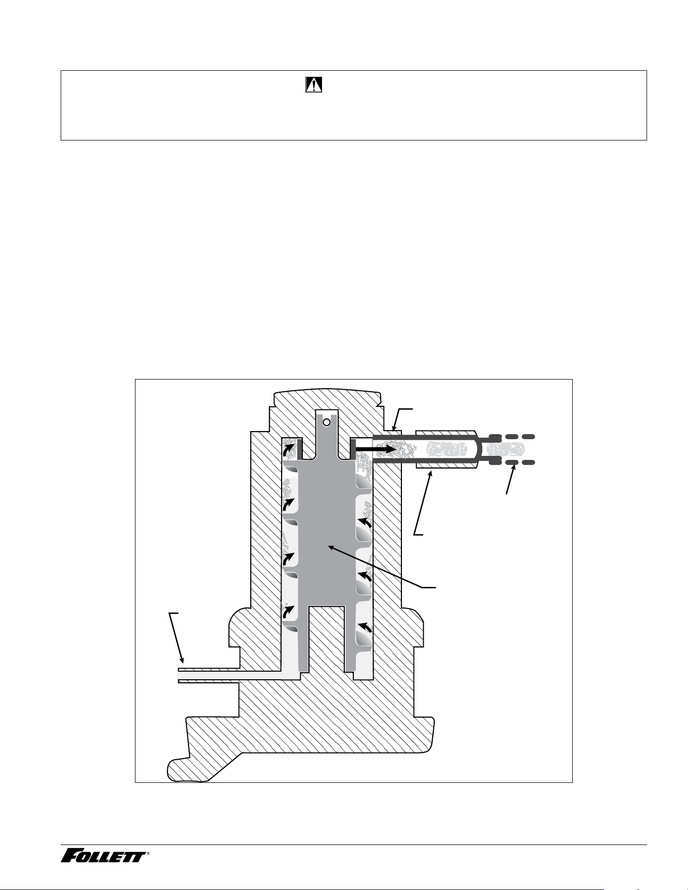
How the Machine Works
Follett’s automatic-load icemaker is equipped with Follett’s 425 lb (193 kg)/day ice technology. In the continuous
icemaking process, water freezes to the inside wall of the evaporator. A rotating stainless steel auger carries
the ice to the top of the evaporator where it is compressed and extruded through an outlet port. The ice is then
pushed through a tube to the integrated ice storage bin. When the bin is full, a bin thermostat opens and turn
OFF the icemaker.
A solid state control board located in the electrical box of the icemaker controls the normal operation of the
icemaker and monitors gearmotor torque. This control board will shut down the icemaker should an overtorque
condition occur. It is very important that you familiarize yourself with the operational sequences detailed in this
manual before attempting to service the icemaker.
Ice enters the integrated ice bin. Using the scoop supplied with the unit, you can easily take the ice out of the bin.
There is a scoop holder located on the internal wall. When ice is emptied from the ice bin, the thermostat capillary
tube gets warm and signals the machine to produce ice. There is no need turn off the machine during its normal
operation.
water
inlet
auger
compression nozzle
ice transport tube
evaporator
port
16 Integrated Icemaker R290
Accessing Internal Components
CAUTION!
§ Except for routine cleaning and sanitizing, only qualied technicians should attempt to service or maintain this
equipment.
§ Use caution when sliding out the bin.
Ice Bin Removal
1. Empty all the ice from the bin.
2. Remove the front grille (Fig. 15.1).
3. Remove two screws behind the grille
(Fig.15.2).
4. Shut off the bin drain valve and remove the
drain tube from the ice bin (Fig. 16).
5. Facing the unit, slide the bin out by pulling it
towards you.
Fig. 15
ICE BIN
FRONT
GRILLE
SCREWS
ICEMAKER
THERMOSTAT
2
1
Fig. 16
STORAGE
BIN
DRAIN
TUBE
SHUT-OFF
VALVE
Integrated Icemaker R290 17
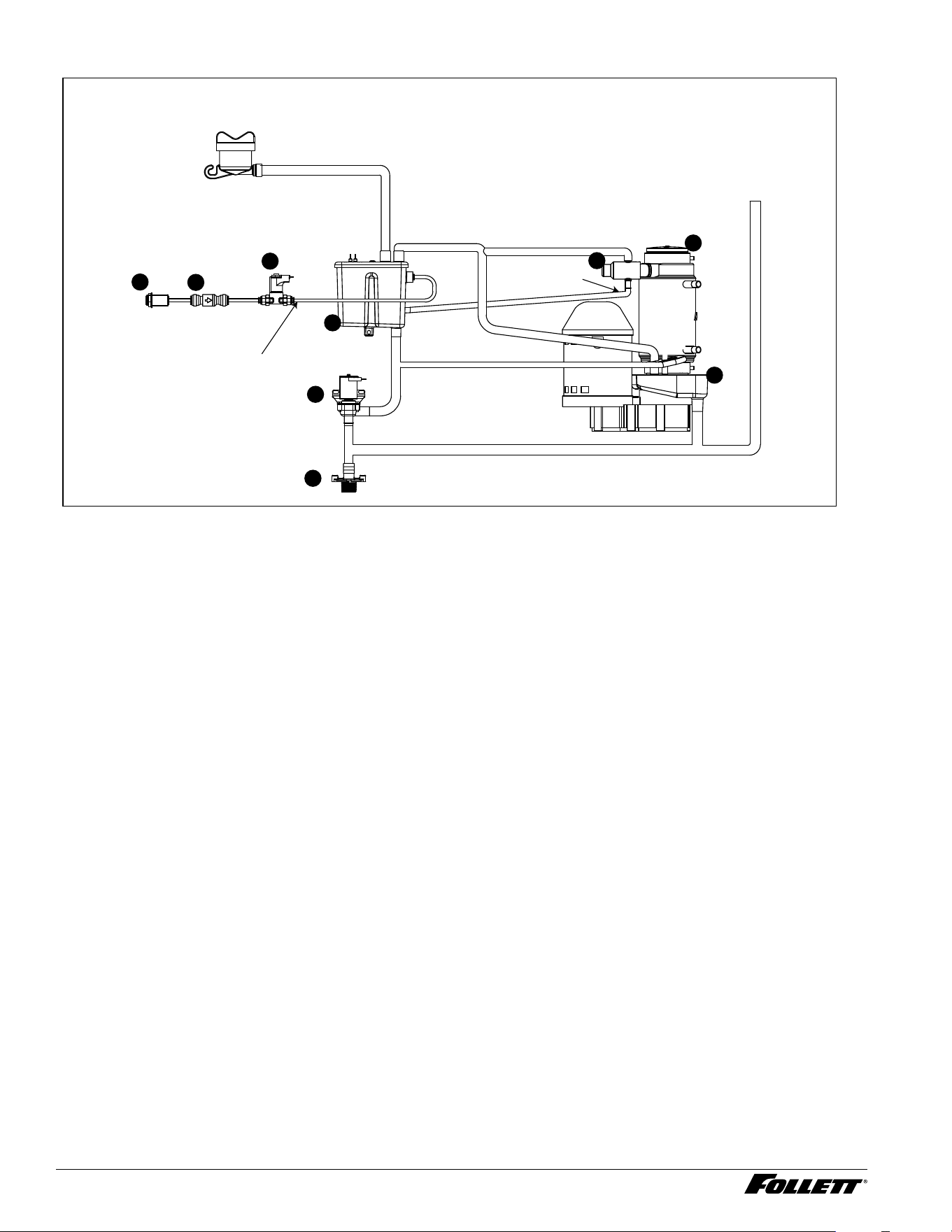
Water System
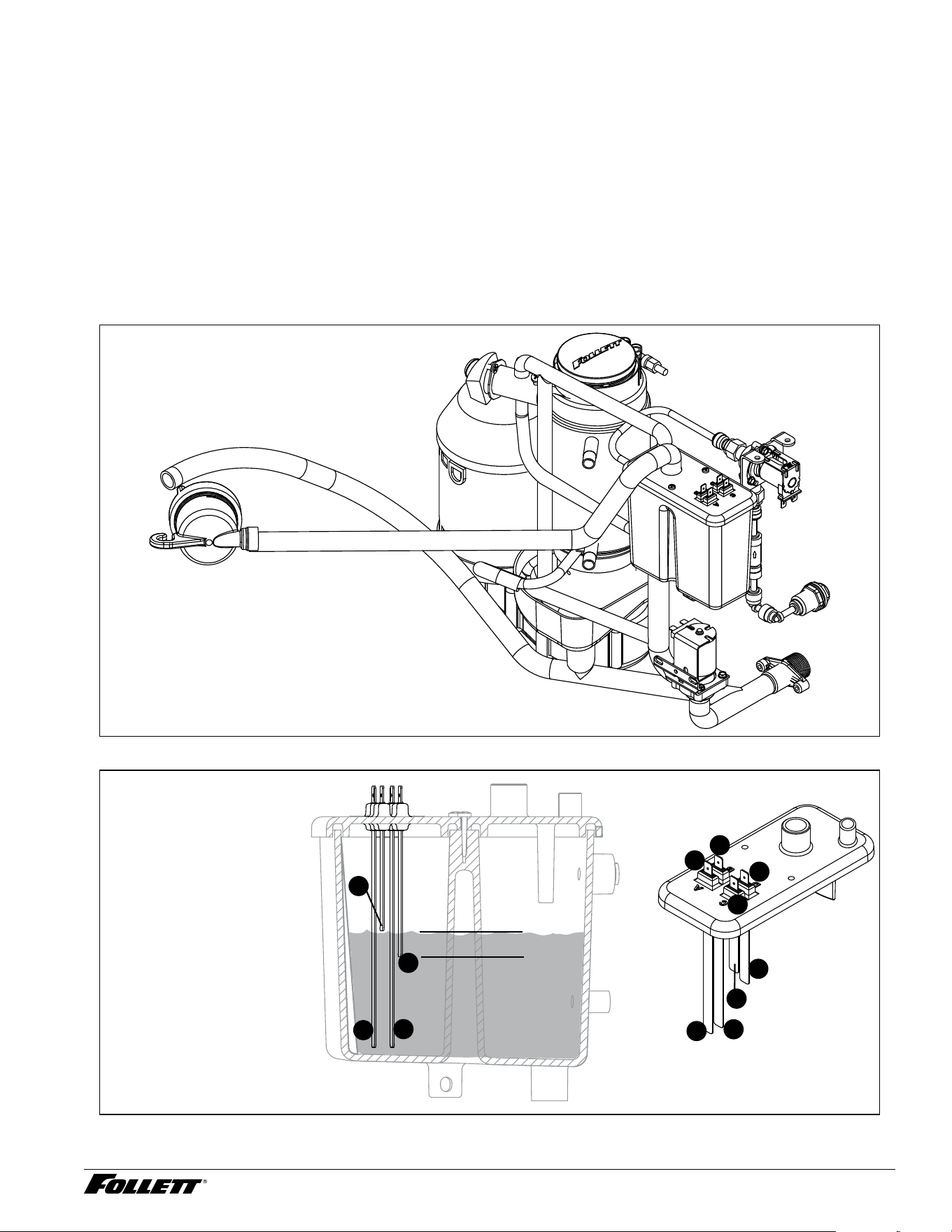
The water level in the evaporator is controlled by a feed solenoid and level detecting sensors. Referencing the
diagram below, water sensing rods extend down into the reservoir. The system works via electrical conductivity as
follows:
One of the longest probes is a Common. When water is between any of the other probes and the common, the
PC board will sense the activation. During normal operation, the water level rises and falls between the Normal
High and Normal Low sensors. As water is consumed to make ice, the water level will fall until the Normal Low
sensor is exposed, triggering the water feed solenoid to turn on. Water will ll until the Normal High sensor is
activated.
Note: The potable water dissolved solids content must be greater than 10 ppm for the water control
system to function properly. If using a reverse osmosis water ltration system, ensure TDS (total
dissolved solids) level is greater than 10 ppm.
Fig. 17
Fig. 18 - Water Reservoir
A ALARM LOW (RED)
B COMMON (BLACK)
C NORMAL HIGH (ORANGE)
D NORMAL LOW (YELLOW)
B
A
B
A
C
D
C
D
NORMAL OPERATING RANGE
B
A
C
D
18 Integrated Icemaker R290
Fig. 19
DRAIN LINE
FEED LINE
DRAIN
OVERFLOW
WATER
SUPPLY
CLEANING
CUP
SANITIZING LINE
1
2
3
4
5
6
7
8
9
ICE BIN MELT
WATER
1 Push in water inlet 3/8" 6 Drain outlet 3/4"
2 Check valve 7 Evaporator and gearmotor assembly
3 Water feed solenoid valve 8 Ice compression nozzle
4 Water reservoir 9 Drain pan
5 Purge valve
Integrated Icemaker R290 19
Electrical System
ATTENTION!
To prevent circuit breaker overload, wait 15 minutes before restarting this unit. This allows the compressor
to equalize and the evaporator to thaw.
Normal Control Board Operation
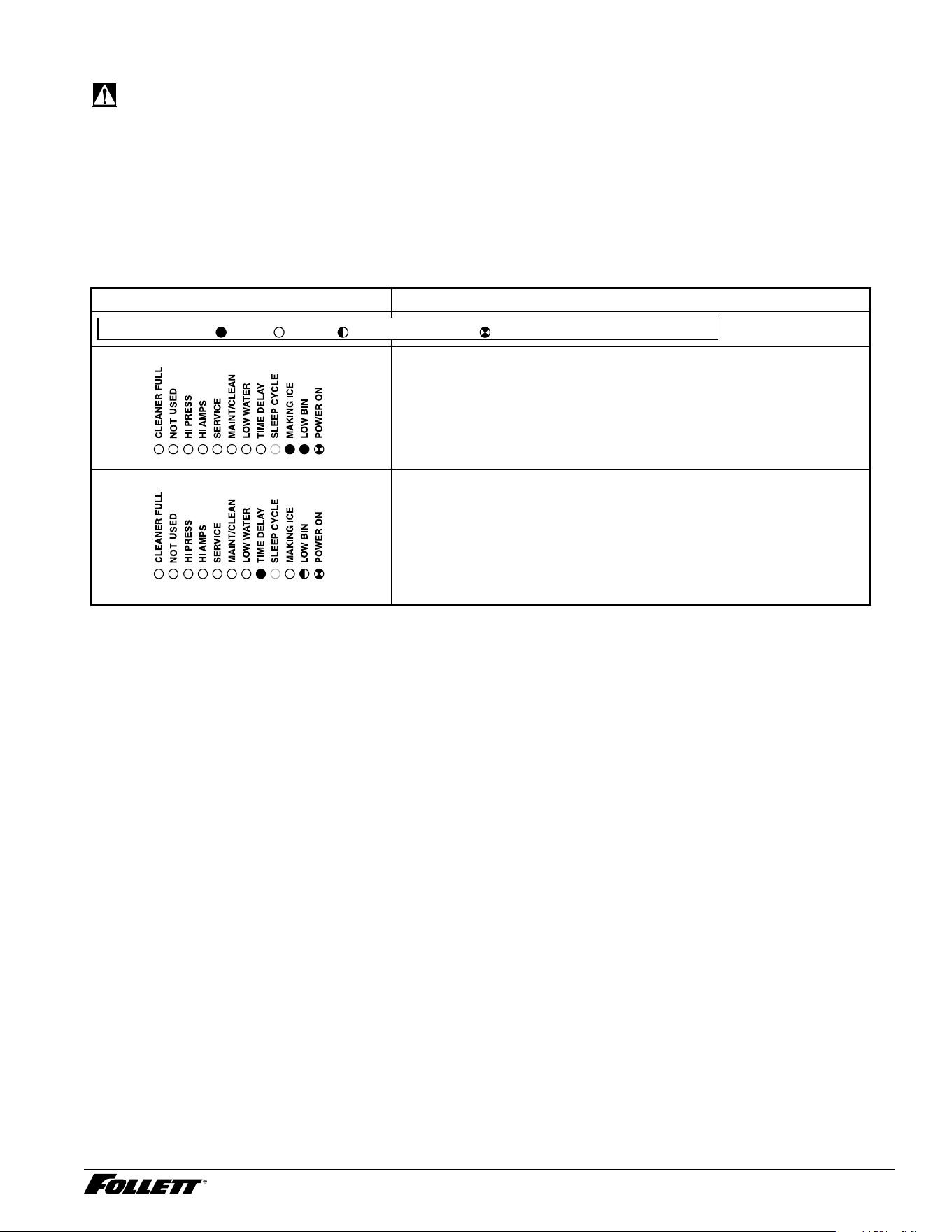
The PC board indicator lights provide all the information necessary to determine the machine’s status. Green
indicator lights generally represent "go" or normal operation; Yellow indicators represent normal off conditions; Red
indicators generally represent alarm conditions, some of which will lock the machine OFF.
A ashing green light labeled POWER indicates power to the machine. All other normal operation status indicators
are covered as follows:
Icemaker disposition Operating conditions
FLASHINGON or OFF
Legend:
OFFON
1. Icemaker is making ice. 1. Normal running.
2. Icemaker is not making ice.
2. Normal time delay. When the bin lls with ice, the LOW BIN
light goes out momentarily and the refrigeration and auger
drive systems immediately shut down. (Note: The fan motor will
continue to run for 10 minutes to cool condenser). The TIME
DELAY LED lights, initiating the time delay period. When the
time delay expires, the machine will restart as long as the LOW
BIN light is on.

20 Integrated Icemaker R290
Error Faults:
The PC board monitors various operating parameters including high pressure, auger gearmotor amperage limits,
and low water alarm conditions. There are two types of errors namely "hard" or "soft". A hard error is one that
shuts the machine off and will not allow restart until the reset button is pressed. Even cycling power will not reset
a hard error.
A soft error can either be automatically reset should the condition rectify, or if power is cycled. Should an error
occur, consult the troubleshooting guide in this manual or a Follett service technician.
Soft Errors:
HI AMPS: The PC board monitors the amperage of the auger motor. Should the gear motor experience current
draw above the allowable limit, the machine will shut down and the TIME DELAY and HI AMP will be illuminated.
After the time delay, the machine will restart and the TIME DELAY and HI AMP will clear. HI AMPS will also occur
if the PC board detects no gear motor amperage (0A - gear motor disconnected).
LO WATER: During operation, the water level cycles between the normal low and normal high sensors. Should
the water be shut off to a running machine, a soft error will occur. The error sequence is as follows: During
operation, the water level falls to the normal low sensor, and when it does the water feed solenoid is energized.
If water is not detected at the normal low sensor within 10 seconds, a soft error will occur. The machine will shut
down, but the water feed solenoid will remain energized. Should water return, it will ll to the normal low sensor
and the machine will resume normal operation. The error will clear automatically.
HI PRESSURE: Should the refrigeration pressure rise above 425 psi, the machine will shut down and the TIME
DELAY and HIGH PRESSURE will be illuminated. After the time delay, and if the pressure has fallen back below
the reset point of 295 psi, the machine will restart and the TIME DELAY and HIGH PRESSURE will clear.
Hard Error:
HI AMPS: If a second hi-amp error occurs within 1 hour of the initial hi-amp error, the icemaker will shut off and
the reset on the board must be pressed to clear the error. If a second hi-amp has occurred, the HI AMP LED only
will be illuminated.
Relay/triac Output Indication:
Each relay on the board has an indicator light associated with its output. For example, when the relay for the
water feed solenoid is energized, the adjacent indicator light glows green.
Flushing Logic:
Off cycle: At the completion of off-cycle time delay, the machine checks for a cumulative one (1) hour of ice
making time since the last off-cycle ush. If the cumulative ice making time exceeds one (1) hour, the machine
will open the drain valve for 60 seconds to drain the evaporator in its entirety. It will then rell with water and begin
making ice. If the ice making time is less than 1 hour, the machine will start and begin making ice without draining
the evaporator.
Integrated Icemaker R290 21
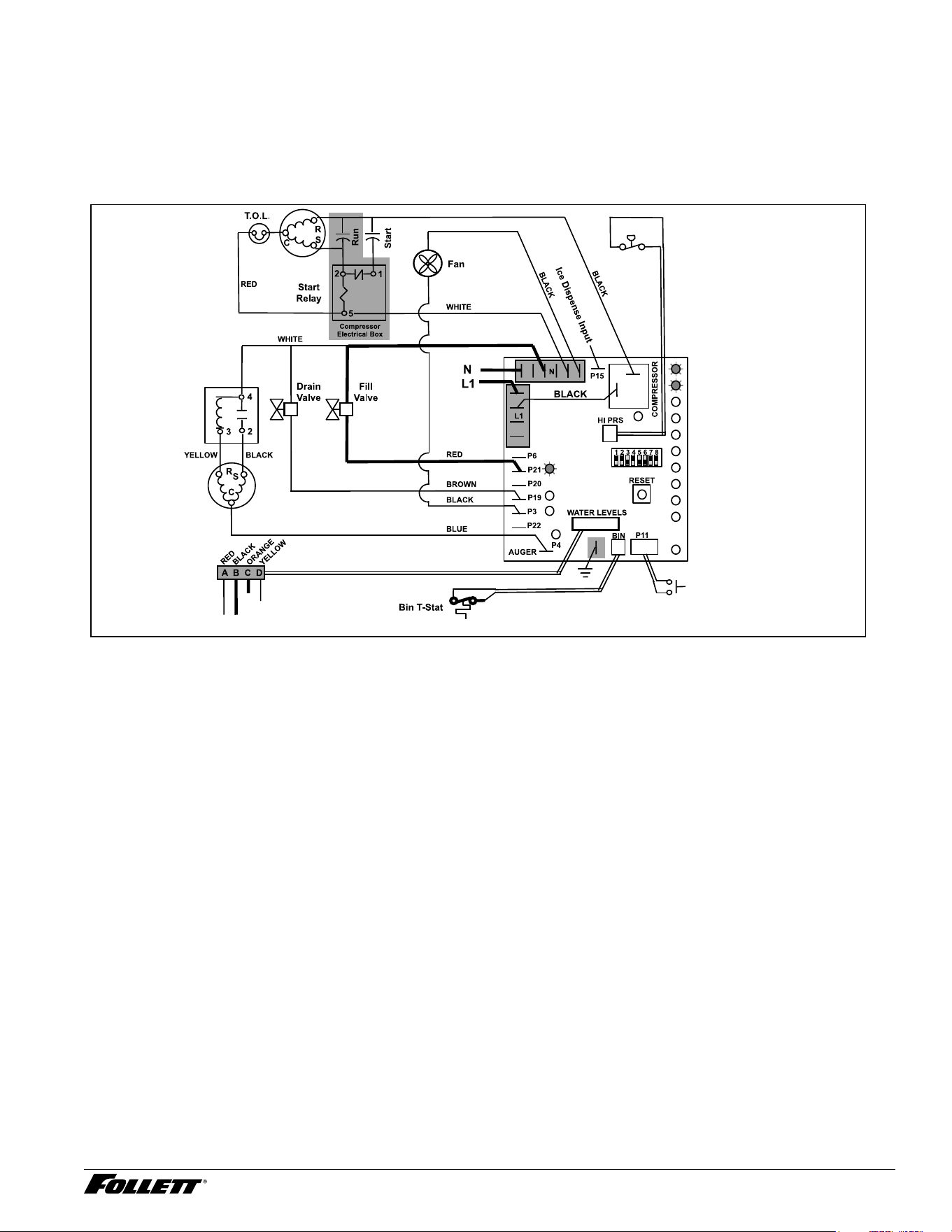
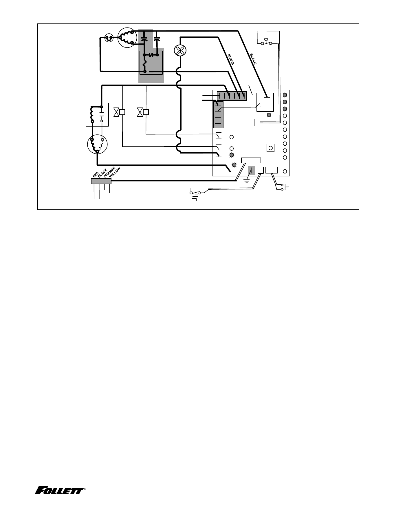
Starting Procedure
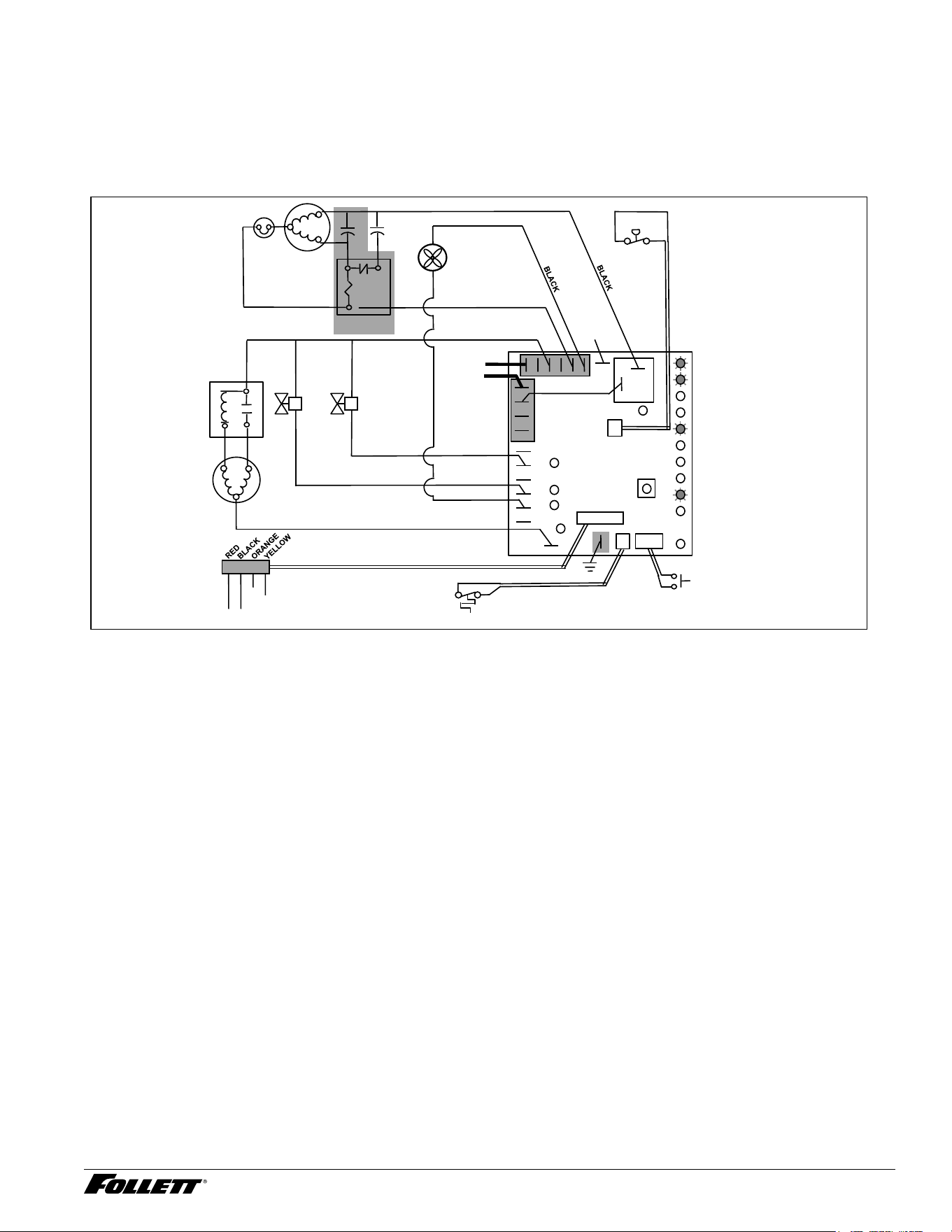
Normal Operation – Stage 1
Power is supplied to L1 of the control board, the POWER LED light begins ashing. The ice level bin thermostat in
the dispenser is closed and calling for ice, supplying contact closure to the control board. The LOW BIN LED will
be lit. The control board will now go through the start-up sequence. The board checks the water sensors (located
in the reservoir) for continuity between the common probe (B) and the high probe (C). If continuity is not sensed,
the water ll valve (P21) is energized.
Compressor
MAINTENANCE
LOW WATER
TIME DELAY
SLEEP CYCLE
MAKING ICE
LOW BIN
POWER
SERVICE
HI AMPS
HI PRESSURE
CLEANER FULL
Gearmotor
Water Sensors
Clean Switch
High
Pressure
Switch
Start
Relay
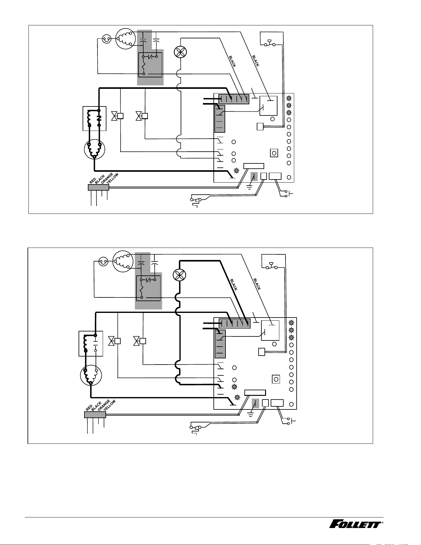
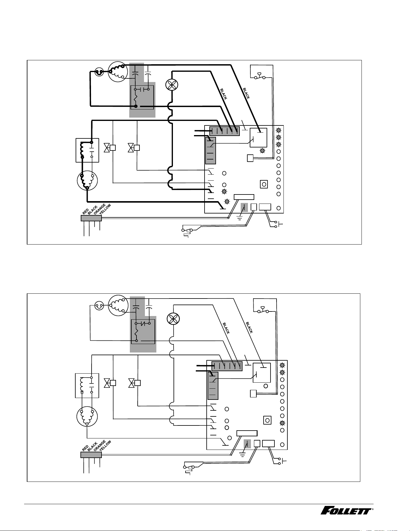
Normal Operation – Stage 2
When continuity is seen between B and C, the water valve de-energizes, the AUGER output (P4) comes on along
with the MAKING ICE LED. The auger gearmotor’s start windings are energized through a current style start relay
that is pulled in by the initial high current draw of the gearmotor.
22 Integrated Icemaker R290
5
2
1
Start
Run
Compressor
T.O.L.
MAINTENANCE
LOW WATER
TIME DELAY
SLEEP CYCLE
MAKING ICE
LOW BIN
POWER
SERVICE
HI AMPS
HI PRESSURE
CLEANER FULL
High
Pressure
Switch
R
S
C
Gearmotor
Start
Relay
Start
Relay
N
L1
Fan
A B C D
Water Sensors
RESET
Fill
Valve
Drain
Valve
3
4
2
Bin T-Stat
Clean Switch
P6
P21
P20
P19
P3
P22
P4
AUGER
WATER LEVELS
BIN
P11
HI PRS
L1
R
S
C
RED
WHITE
WHITE
BLACK
BROWN
BLUE
RED
BLACK YELLOW
Compressor
Electrical Box
COMPRESSOR
1 2 3 4 5 6 7 8
BLACK
N
P15
Ice Dispense Input
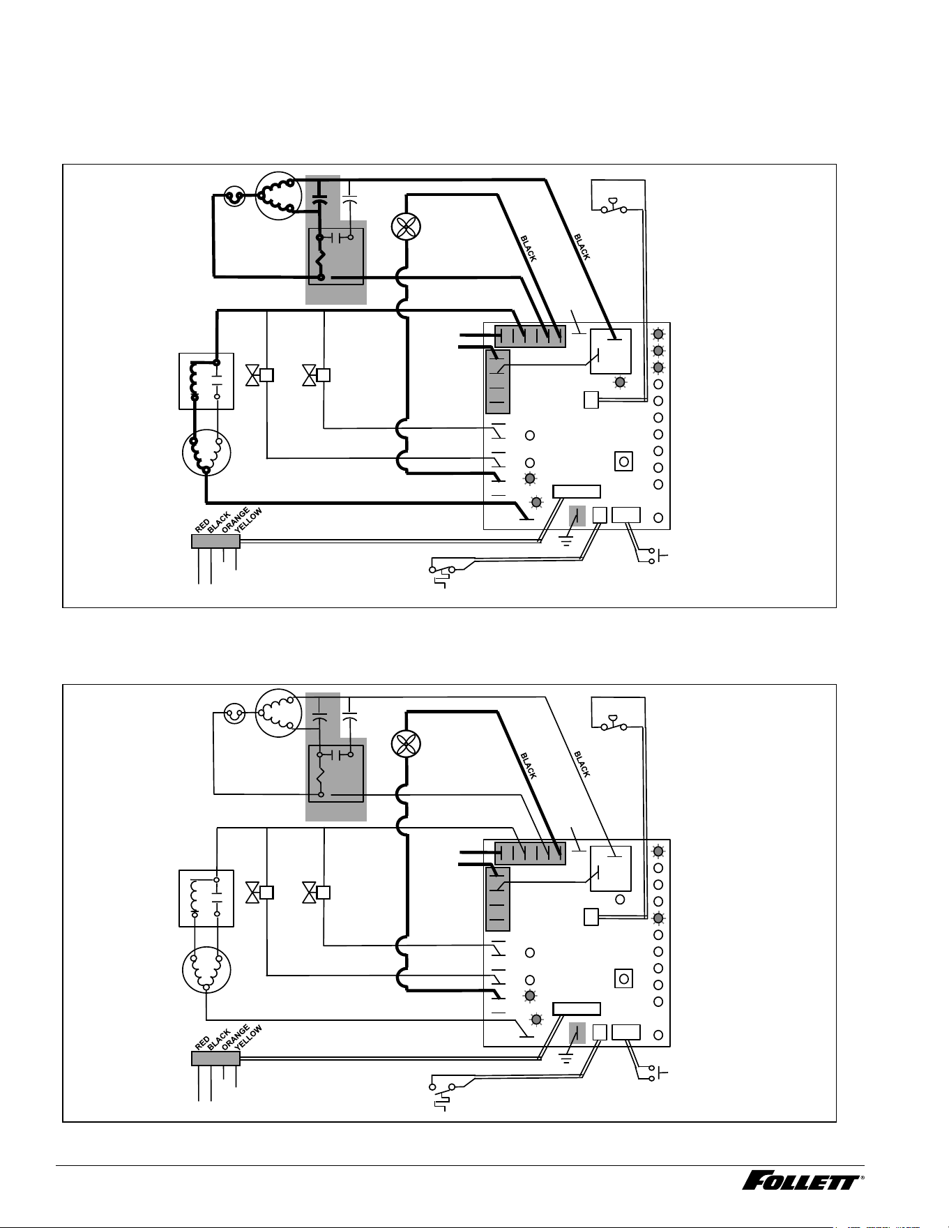
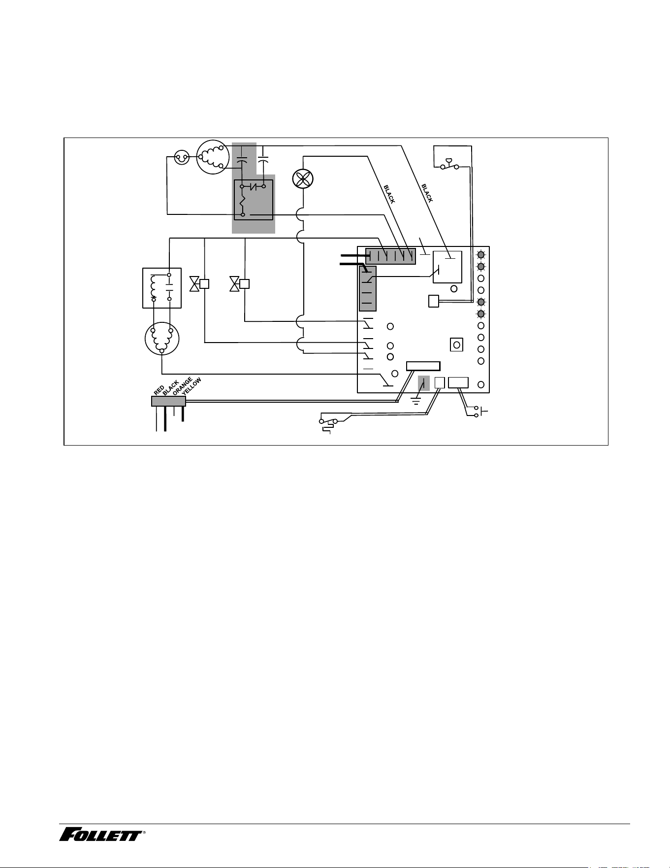
Normal Operation – Stage 3
After the initial high current draw drops off, the gearmotor start relay contacts open, dropping out the start winding.
The condenser fan output (P3) comes on 0.5 seconds later.
5
2
1
Start
Run
Compressor
T.O.L.
MAINTENANCE
LOW WATER
TIME DELAY
SLEEP CYCLE
MAKING ICE
LOW BIN
POWER
SERVICE
HI AMPS
HI PRESSURE
CLEANER FULL
High
Pressure
Switch
R
S
C
Gearmotor
Start
Relay
Start
Relay
N
L1
Fan
A B C D
Water Sensors
RESET
Fill
Valve
Drain
Valve
3
4
2
Bin T-Stat
Clean Switch
P6
P21
P20
P19
P3
P22
P4
AUGER
WATER LEVELS
BIN
P11
HI PRS
L1
R
S
C
RED
WHITE
WHITE
BLACK
BROWN
BLUE
RED
BLACK YELLOW
Compressor
Electrical Box
COMPRESSOR
1 2 3 4 5 6 7 8
BLACK
N
P15
Ice Dispense Input
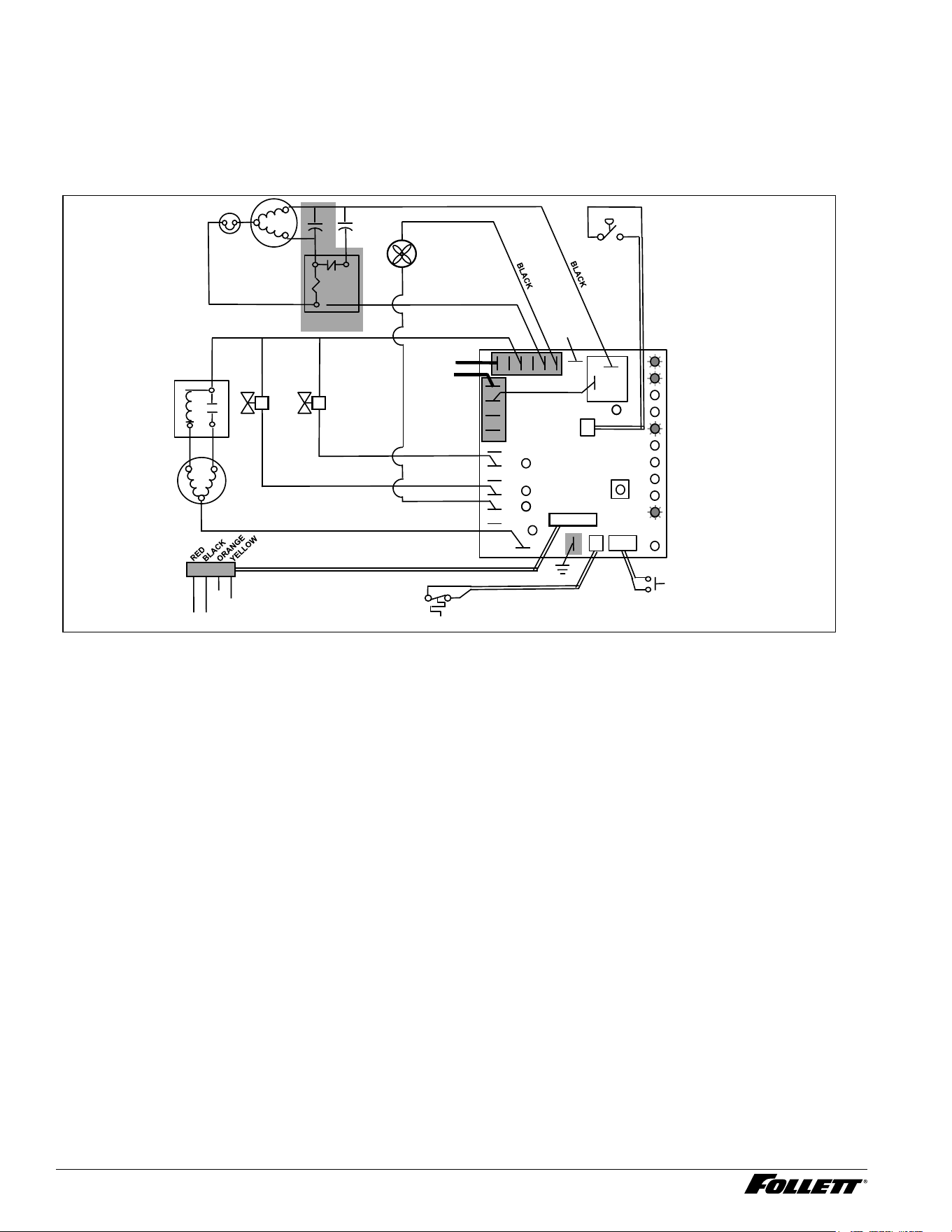
Normal Operation – Stage 4
One second (1 s) after the fan comes on, the COMPRESSOR output comes on. The compressor circuit uses both
run and start capacitors along with a potential start relay. The start capacitor in energized through the normally
closed contacts of the start relay.
Integrated Icemaker R290 23
5
2
1
Start
Run
Compressor
T.O.L.
MAINTENANCE
LOW WATER
TIME DELAY
SLEEP CYCLE
MAKING ICE
LOW BIN
POWER
SERVICE
HI AMPS
HI PRESSURE
CLEANER FULL
High
Pressure
Switch
R
S
C
Gearmotor
Start
Relay
Start
Relay
N
L1
Fan
A B C D
Water Sensors
RESET
Fill
Valve
Drain
Valve
3
4
2
Bin T-Stat
Clean Switch
P6
P21
P20
P19
P3
P22
P4
AUGER
WATER LEVELS
BIN
P11
HI PRS
L1
R
S
C
RED
WHITE
WHITE
BLACK
BROWN
BLUE
RED
BLACK YELLOW
Compressor
Electrical Box
COMPRESSOR
1 2 3 4 5 6 7 8
BLACK
N
P15
Ice Dispense Input
24 Integrated Icemaker R290
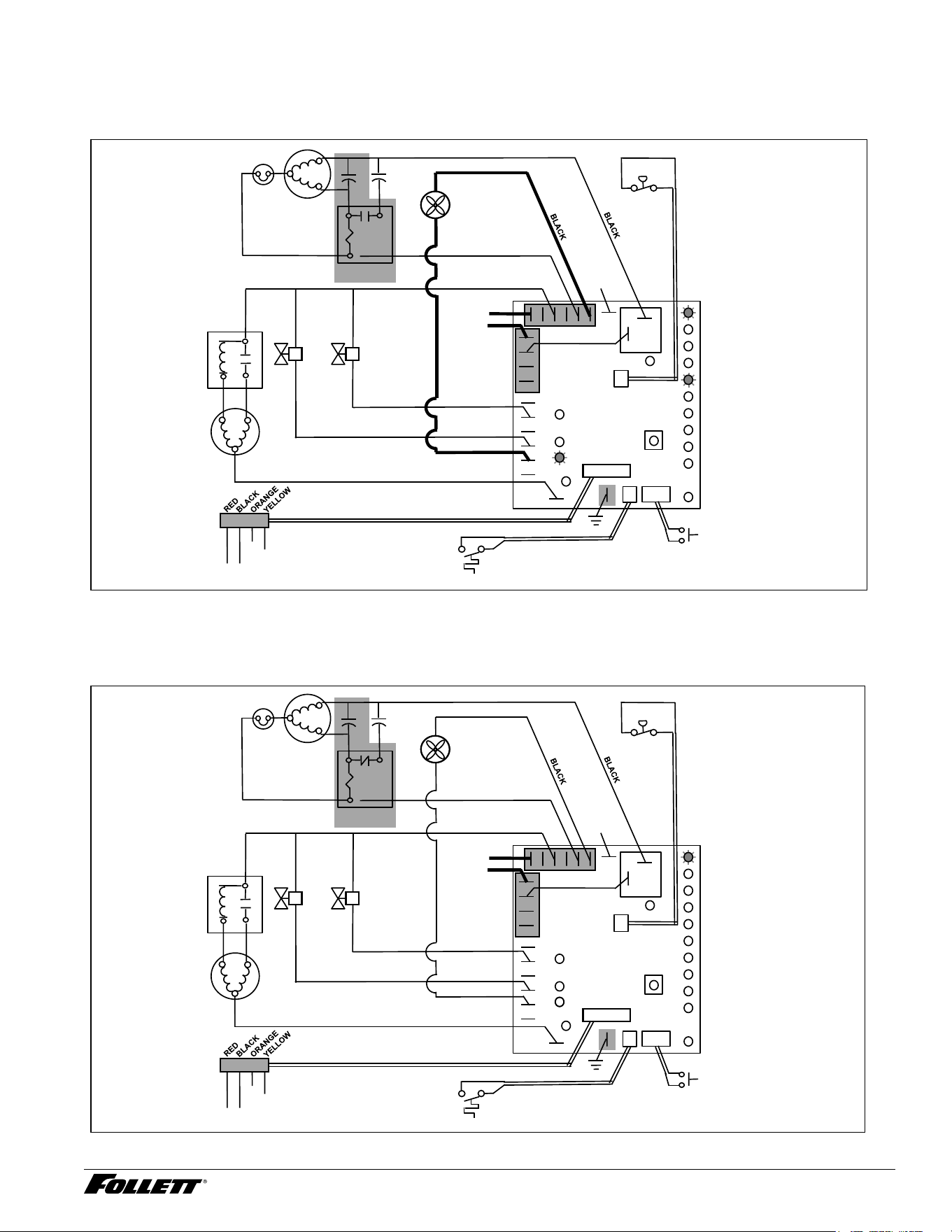
Normal Operation – Stage 5
As the compressor comes up to normal running speed, its start winding generates a voltage potential across the
relay’s coil. This energizes the coil to open the contact and drop out the start capacitor.
The icemaker is now in a normal ice making mode. The icemaker will produce ice until the bin level control in the
ice dispenser is satised.
5
2
1
Start
Run
Compressor
T.O.L.
MAINTENANCE
LOW WATER
TIME DELAY
SLEEP CYCLE
MAKING ICE
LOW BIN
POWER
SERVICE
HI AMPS
HI PRESSURE
CLEANER FULL
High
Pressure
Switch
R
S
C
Gearmotor
Start
Relay
Start
Relay
N
L1
Fan
A B C D
Water Sensors
RESET
Fill
Valve
Drain
Valve
3
4
2
Bin T-Stat
Clean Switch
P6
P21
P20
P19
P3
P22
P4
AUGER
WATER LEVELS
BIN
P11
HI PRS
L1
R
S
C
RED
WHITE
WHITE
BLACK
BROWN
BLUE
RED
BLACK YELLOW
Compressor
Electrical Box
COMPRESSOR
1 2 3 4 5 6 7 8
BLACK
N
P15
Ice Dispense Input
Normal Operation – Stage 6
Once the bin thermostat control opens, the LOW BIN LED goes out. After a 10 second delay the compressor
output turns off, the MAKING ICE LED goes out and the TIME DELAY LED comes on.
5
2
1
Start
Run
Compressor
T.O.L.
MAINTENANCE
LOW WATER
TIME DELAY
SLEEP CYCLE
MAKING ICE
LOW BIN
POWER
SERVICE
HI AMPS
HI PRESSURE
CLEANER FULL
High
Pressure
Switch
R
S
C
Gearmotor
Start
Relay
Start
Relay
N
L1
Fan
A B C D
Water Sensors
RESET
Fill
Valve
Drain
Valve
3
4
2
Bin T-Stat
Clean Switch
P6
P21
P20
P19
P3
P22
P4
AUGER
WATER LEVELS
BIN
P11
HI PRS
L1
R
S
C
RED
WHITE
WHITE
BLACK
BROWN
BLUE
RED
BLACK YELLOW
Compressor
Electrical Box
COMPRESSOR
1 2 3 4 5 6 7 8
BLACK
N
P15
Ice Dispense Input
Integrated Icemaker R290 25
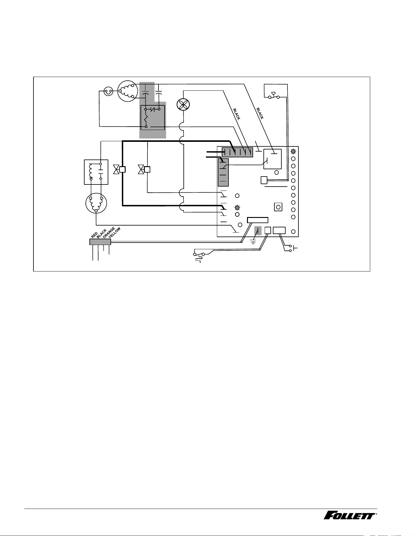
Normal Operation – Stage 7
The fan motor continues for 10 minutes before shutting off. The TIME DELAY LED remains on for 20 minutes. The
icemaker will not start while the TIME DELAY LED is on. To restart the icemaker for troubleshooting purposes,
depress the reset button to clear the control board.
5
2
1
Start
Run
Compressor
T.O.L.
MAINTENANCE
LOW WATER
TIME DELAY
SLEEP CYCLE
MAKING ICE
LOW BIN
POWER
SERVICE
HI AMPS
HI PRESSURE
CLEANER FULL
High
Pressure
Switch
R
S
C
Gearmotor
Start
Relay
Start
Relay
N
L1
Fan
A B C D
Water Sensors
RESET
Fill
Valve
Drain
Valve
3
4
2
Bin T-Stat
Clean Switch
P6
P21
P20
P19
P3
P22
P4
AUGER
WATER LEVELS
BIN
P11
HI PRS
L1
R
S
C
RED
WHITE
WHITE
BLACK
BROWN
BLUE
RED
BLACK YELLOW
Compressor
Electrical Box
COMPRESSOR
1 2 3 4 5 6 7 8
BLACK
N
P15
Ice Dispense Input
Normal Operation – Stage 8
When the dwell time of 20 minutes has expired, the TIME DELAY LED goes off. If 5 seconds of ice has been
dispensed and the SLEEP CYCLE LED is off, the icemaker will go through the normal start-up sequence when
the bin level control signals the control board for ice.
5
2
1
Start
Run
Compressor
T.O.L.
MAINTENANCE
LOW WATER
TIME DELAY
SLEEP CYCLE
MAKING ICE
LOW BIN
POWER
SERVICE
HI AMPS
HI PRESSURE
CLEANER FULL
High
Pressure
Switch
R
S
C
Gearmotor
Start
Relay
Start
Relay
N
L1
Fan
A B C D
Water Sensors
RESET
Fill
Valve
Drain
Valve
3
4
2
Bin T-Stat
Clean Switch
P6
P21
P20
P19
P3
P22
P4
AUGER
WATER LEVELS
BIN
P11
HI PRS
L1
R
S
C
RED
WHITE
WHITE
BLACK
BROWN
BLUE
RED
BLACK YELLOW
Compressor
Electrical Box
COMPRESSOR
1 2 3 4 5 6 7 8
BLACK
N
P15
Ice Dispense Input
26 Integrated Icemaker R290
Self-ushing
At the completion of the 20 minute time delay, the machine checks for a cumulative one hour of ice making time
since the last off-cycle ush. If the cumulative ice making time exceeds one hour, the machine will energize the
drain valve P19 for 60 seconds to drain the evaporator. It will then rell with water, ush again, rell and begin
making ice if the LOW BIN LED is on. If the ice making time is less than 1 hour, the machine will start and begin
making ice without draining the evaporator.
5
2
1
Start
Run
Compressor
T.O.L.
MAINTENANCE
LOW WATER
TIME DELAY
SLEEP CYCLE
MAKING ICE
LOW BIN
POWER
SERVICE
HI AMPS
HI PRESSURE
CLEANER FULL
High
Pressure
Switch
R
S
C
Gearmotor
Start
Relay
Start
Relay
N
L1
Fan
A B C D
Water Sensors
RESET
Fill
Valve
Drain
Valve
3
4
2
Bin T-Stat
Clean Switch
P6
P21
P20
P19
P3
P22
P4
AUGER
WATER LEVELS
BIN
P11
HI PRS
L1
R
S
C
RED
WHITE
WHITE
BLACK
BROWN
BLUE
RED
BLACK YELLOW
Compressor
Electrical Box
COMPRESSOR
1 2 3 4 5 6 7 8
BLACK
N
P15
Ice Dispense Input
Integrated Icemaker R290 27
Diagnostic Stages
High Gearmotor Amps – Stage 1
The HI AMPS error and TIME DELAY LEDs are on indicating that the control board has sensed an over-torque
condition at the P4 terminal (more than 3A from the gearmotor) and shut the icemaker down (strike one). The HI
AMPS and TIME DELAY LEDs will remain on for 60 minutes after an over-torque condition has occurred. The
icemaker will remain off as long as these two LEDs are on. After the 60 minute time delay, these LED lights turn
off, and the control board will try to go through a normal start-up sequence.
5
2
1
Start
Run
Compressor
T.O.L.
MAINTENANCE
LOW WATER
TIME DELAY
SLEEP CYCLE
MAKING ICE
LOW BIN
POWER
SERVICE
HI AMPS
HI PRESSURE
CLEANER FULL
High
Pressure
Switch
R
S
C
Gearmotor
Start
Relay
Start
Relay
N
L1
Fan
A B C D
Water Sensors
RESET
Fill
Valve
Drain
Valve
3
4
2
Bin T-Stat
Clean Switch
P6
P21
P20
P19
P3
P22
P4
AUGER
WATER LEVELS
BIN
P11
HI PRS
L1
R
S
C
RED
WHITE
WHITE
BLACK
BROWN
BLUE
RED
BLACK YELLOW
Compressor
Electrical Box
COMPRESSOR
1 2 3 4 5 6 7 8
BLACK
N
P15
Ice Dispense Input
28 Integrated Icemaker R290
High Gearmotor Amps – Stage 2
If the restart is successful the board will continue to monitor the current draw on P4 for 60 minutes looking for a
second high amps (above 3A) occurrence. If the icemaker runs without problems for 60 minutes and no additional
torque errors occur, the icemaker will continue normal operation.
5
2
1
Start
Run
Compressor
T.O.L.
MAINTENANCE
LOW WATER
TIME DELAY
SLEEP CYCLE
MAKING ICE
LOW BIN
POWER
SERVICE
HI AMPS
HI PRESSURE
CLEANER FULL
High
Pressure
Switch
R
S
C
Gearmotor
Start
Relay
Start
Relay
N
L1
Fan
A B C D
Water Sensors
RESET
Fill
Valve
Drain
Valve
3
4
2
Bin T-Stat
Clean Switch
P6
P21
P20
P19
P3
P22
P4
AUGER
WATER LEVELS
BIN
P11
HI PRS
L1
R
S
C
RED
WHITE
WHITE
BLACK
BROWN
BLUE
RED
BLACK YELLOW
Compressor
Electrical Box
COMPRESSOR
1 2 3 4 5 6 7 8
BLACK
N
P15
Ice Dispense Input
High Gearmotor Amps – Stage 3
If a second occurrence happens during the 60 minute monitoring period, the HI AMPS LED will come on again
and shut the machine down (strike two). The HI AMPS LED (without the TIME DELAY LED) will indicate to the
technician that two consecutive over-torque situations have occurred. The icemaker is shut down at this time and
locked out. It will not restart unless the manual reset button is depressed while power is on.
5
2
1
Start
Run
Compressor
T.O.L.
MAINTENANCE
LOW WATER
TIME DELAY
SLEEP CYCLE
MAKING ICE
LOW BIN
POWER
SERVICE
HI AMPS
HI PRESSURE
CLEANER FULL
High
Pressure
Switch
R
S
C
Gearmotor
Start
Relay
Start
Relay
N
L1
Fan
A B C D
Water Sensors
RESET
Fill
Valve
Drain
Valve
3
4
2
Bin T-Stat
Clean Switch
P6
P21
P20
P19
P3
P22
P4
AUGER
WATER LEVELS
BIN
P11
HI PRS
L1
R
S
C
RED
WHITE
WHITE
BLACK
BROWN
BLUE
RED
BLACK YELLOW
Compressor
Electrical Box
COMPRESSOR
1 2 3 4 5 6 7 8
BLACK
N
P15
Ice Dispense Input
Integrated Icemaker R290 29
Loss of Water
During operation, the water level cycles between the normal low (D) and normal high (C) water probes - the ll
valve (P21) cycling on and off. If continuity is not detected between the common probe (B) and normal low (D)
within 10 seconds, the LOW WATER and TIME DELAY LEDs will come on and the machine will shut down for
the one hour time delay period. After the time delay, the ll valve will re-energize and wait for continuity between
the common probe and normal high before restarting. LOW WATER LED will remain on until the water level is
satised.
5
2
1
Start
Run
Compressor
T.O.L.
MAINTENANCE
LOW WATER
TIME DELAY
SLEEP CYCLE
MAKING ICE
LOW BIN
POWER
SERVICE
HI AMPS
HI PRESSURE
CLEANER FULL
High
Pressure
Switch
R
S
C
Gearmotor
Start
Relay
Start
Relay
N
L1
Fan
A B C D
Water Sensors
RESET
Fill
Valve
Drain
Valve
3
4
2
Bin T-Stat
Clean Switch
P6
P21
P20
P19
P3
P22
P4
AUGER
WATER LEVELS
BIN
P11
HI PRS
L1
R
S
C
RED
WHITE
WHITE
BLACK
BROWN
BLUE
RED
BLACK YELLOW
Compressor
Electrical Box
COMPRESSOR
1 2 3 4 5 6 7 8
BLACK
N
P15
Ice Dispense Input
30 Integrated Icemaker R290
High Refrigerant Pressure
Should the refrigeration pressure rise above 425 psi, the high pressure switch contacts will open. The board sees
the open circuit and the HIGH PRESSURE and TIME DELAY LEDs will come on, the machine shuts down. After
the one hour time delay, the machine will attempt to restart. If the pressure has fallen below the reset point of
295 psi and the board see the contacts closed, the machine will resume normal operation. If the contacts are
still open after the restart, the board will again go into HIGH PRESSURE and TIME DELAY, cycling until contact
closure is seen.
5
2
1
Start
Run
Compressor
T.O.L.
MAINTENANCE
LOW WATER
TIME DELAY
SLEEP CYCLE
MAKING ICE
LOW BIN
POWER
SERVICE
HI AMPS
HI PRESSURE
CLEANER FULL
High
Pressure
Switch
R
S
C
Gearmotor
Start
Relay
Start
Relay
N
L1
Fan
A B C D
Water Sensors
RESET
Fill
Valve
Drain
Valve
3
4
2
Bin T-Stat
Clean Switch
P6
P21
P20
P19
P3
P22
P4
AUGER
WATER LEVELS
BIN
P11
HI PRS
L1
R
S
C
RED
WHITE
WHITE
BLACK
BROWN
BLUE
RED
BLACK YELLOW
Compressor
Electrical Box
COMPRESSOR
1 2 3 4 5 6 7 8
BLACK
N
P15
Ice Dispense Input
Integrated Icemaker R290 31
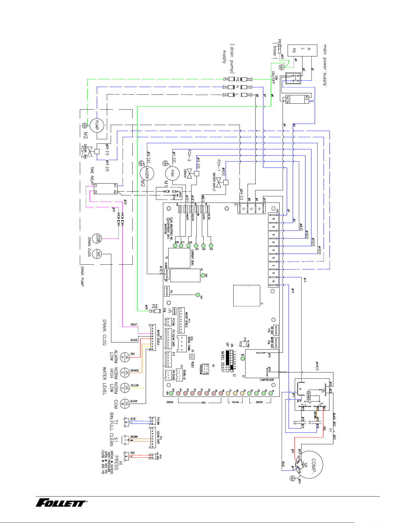
Wiring Diagram
A2
32 Integrated Icemaker R290
Compressor Data
Compressor Current Draw at 115 Vac
Locked rotor amps 44.9A @ 115 V
Ambient air temperature 60 F/15.6 C 70 F/21.1 C 80 F/26.7 C 90 F/32.2 C 100 F/37.8 C
Amperage 4.76 4.94 5.14 5.55 5.84
Low-side pressure (bar/psi) 1.08/15.7 1.09/15.8 1.13/16.4 1.19/17.3 1.22/17.7
High-side pressure (bar/psi) 8.63/125.2 9.79/142 10.89/157.9 12.97/188.1 14.75/213.9
Compressor Current Draw at 230 Vac
Locked rotor amps 21.0A @ 230 V, 50 Hz
Ambient air temperature 60 F/15.6 C 70 F/21.1 C 80 F/26.7 C 90 F/32.2 C 100 F/37.8 C
Amperage 2.25 2.27 2.34 2.4 2.57
Low-side pressure (bar/psi) 1.14/16.5 1.12/16.2 1.16/16.8 1.25/18.1 1.31/19
High-side pressure (bar/psi) 8.13/117.9 9.12/132.3 10.08/146.2 12.11/175.6 13.9/201.6
Gearmotor Data
115 V 230 V
Gearmotor current 1. 76 1. 3
Gearmotor torque-out (high amp) trip point 3.0 1. 8
Locked rotor amps 14A 6.8A
115 Vac 230 Vac
Resistance of windings Yellow to black: 16 Ω Yellow to black: 49 Ω
Black to blue: 7 Ω Black to blue: 33 Ω
Blue to yellow: 10.5 Ω Blue to yellow: 16.7 Ω
115 V 230 V
Compressor start winding 4 Ω 18.4 Ω
Compressor run winding 1 Ω 6 Ω
Fan Motor Data
115 V 230 V
Fan motor current EBM: 0.35 Ω
EC Fan at Drives: : 0.45 Ω
EBM: 0.42 Ω
Integrated Icemaker R290 33
Mechanical System
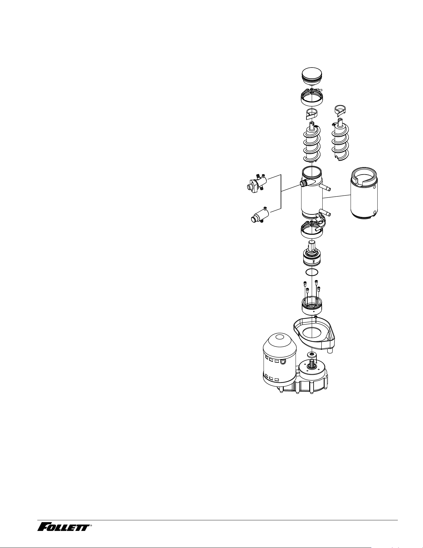
Evaporator Disassembly
1. Press CLEAN SWITCH to purge evaporator.
2. Disconnect power to icemaker when LOW
WATER lights.
3. Shut off water to icemaker.
4. Disconnect plastic tubing from evaporator
water inlet, drain pan stub, compression
nozzle tubing and reservoir overow tubing
from secured clip.
5. Disconnect ice transport tube from
compression nozzle.
6. Loosen nut and remove upper vee-band
coupling from top of evaporator.
7. Lift top bearing assembly straight up with a
slight rotating motion and remove.
8. Remove ice compression loop located at top
of auger.
9. Lift auger straight up and out of evaporator.
10. Remove nut and lower vee-band coupling
from bottom of evaporator.
11. Lift evaporator to clear bottom bearing
assembly.
12. Loosen hex head bolt in side of mounting
base with 5/16 wrench and lift lower bearing
assembly.
13. Remove condensate shield.
14. Remove four allen head machine screws
holding mounting base to gearbox.
15. If replacing evaporator, remove compression
nozzle from evaporator port.
Fig. 20

34 Integrated Icemaker R290
Evaporator Reassembly
1. Clean gearmotor boss, output shaft and shaft well.
2. Install drain pan and evaporator mounting base.
3. Fill gearmotor shaft well with food-grade grease.
4. Install condensate shield and seat against gearmotor boss.
5. Install mounting base O ring in groove in evaporator mounting base.
6. Lower bottom bearing assembly into evaporator mounting base.
7. While maintaining a downward pressure on bottom bearing assembly, tighten hex head bolt with a 5/16
wrench.
8. Position evaporator over lower bearing assembly and align grooves with pins in bearing assembly.
9. Install vee-band clamp and nut and tighten to 70 in/lb.
10. Place auger in center of evaporator and rotate to mate with drive pin.
11. Install ice compression loop, orienting loop as shown.
12. Install upper bearing and seal assembly, rotating bearing to slip pin into auger slot.
13. Install upper vee-band clamp and nut and tighten to 70 in/lb.
14. If evaporator was replaced, reinstall compression nozzle.
Integrated Icemaker R290 35
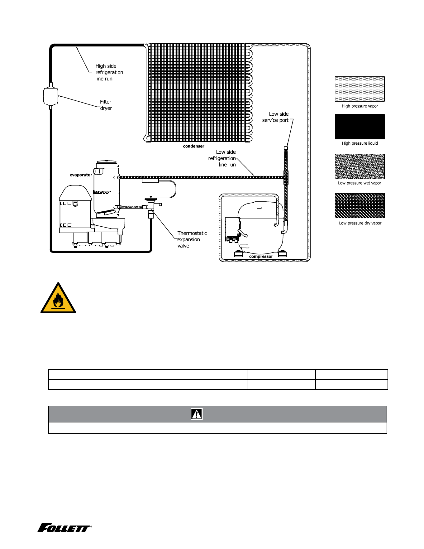
Refrigeration System
Caution: Risk of re.
Refrigeration Charge
All service on refrigeration systems must be performed in accordance with all federal, state and local laws. It is
the responsibility of the technician to ensure that these requirements are met. Recharging icemaker to other than
factory specications will void the warranty.
R425 icemaker charge specications
Model Charge Refrigerant type
UME414A80; UMD414A80; UFE414A80; UFD414A80 99 g (3.49 oz) R290
CAUTION!
§ Recharging of unit at other than factory specications will void icemaker warranty.
36 Integrated Icemaker R290
Ice Capacity Test
Icemaker production capacity can only be determined by weighing ice produced in a specic time period.
1. Remove top panel and hopper lid of unit.
2. Weigh and record weight of container used to catch ice.
3. Run icemaker for at least 15 minutes.
4. Catch ice for 15 or 20 minutes.
5. Weigh harvested ice and record total weight.
6. Subtract weight of container from total weight.
7. Convert fractions of pounds to decimal equivalents (Ex. 6 lbs 8 oz = 6.5 lbs).
8. Calculate production using following formula:
1440 min. x wt. of ice produced
= Production capacity/24 hr. period
Total test time in minutes
9. Calculated amount per 24 hours should be checked against rated capacity for same ambient and water
temperatures in Ice Production Table (see page 6).
Integrated Icemaker R290 37
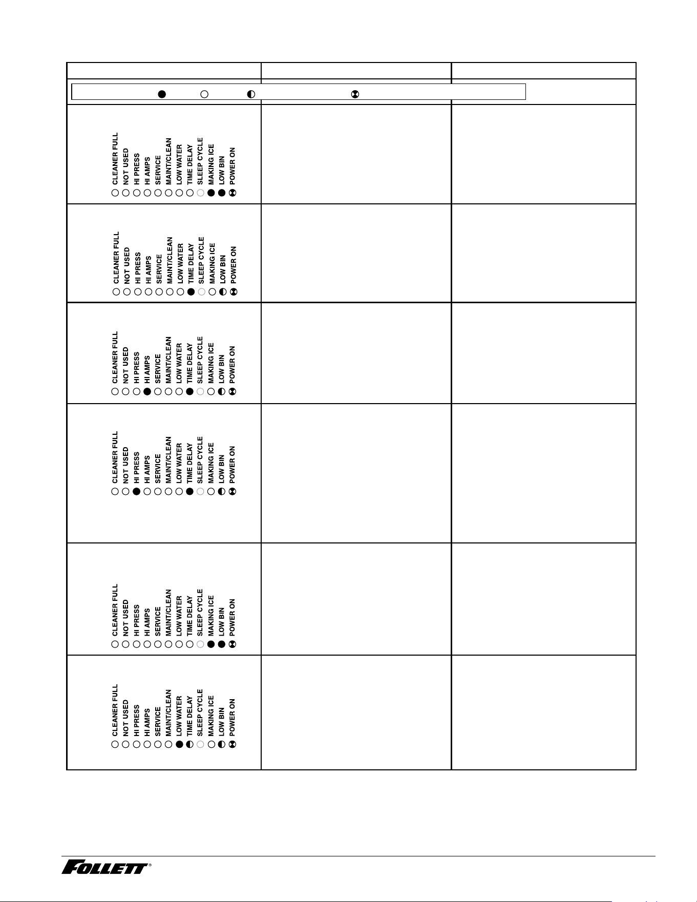
Troubleshooting
Icemaker disposition Possible causes Corrective action
FLASHINGON or OFF
Legend:
OFFON
1. Icemaker is in running
condition but not making ice.
1. Defective compressor.
2. Defective start relay.
3. Defective start capacitor.
4. Defective run capacitor.
5. Defective main contactor.
6. No output from PC board.
7. Machine in Purge cycle.
1. Replace compressor.
2. Replace start relay.
3. Replace start capacitor.
4. Replace run capacitor.
5. Replace main contactor.
6. Replace PC board.
7. Check for Purge operation.
2. Machine in TIME DELAY without full
bin.
1. Damaged or improperly installed
thermostat (open).
1. Replace or reposition thermostat.
3. Icemaker is not making ice.
HI AMPS.
.
1. Poor water quality causing ice to jam
auger.
2. Ice transport tube damaged or bent.
3. Intermittent drive output from
PC board. Evaporator will freeze
causing a hi amps error.
4. Gearmotor is unplugged.
1. Clean icemaker.
2. Inspect ice transport tube - replace
if needed.
3. Replace PC board.
4. Plug in gearmotor.
4. Icemaker is not making ice.
HI PRESSURE.
.
1. High ambient temperatures >100F
(38 C).
2. Poor ventilation or air circulation.
3. Clogged condenser or condenser
lter.
4. Fan not working properly. No air ow.
• Blocked fan blades
• No fan output from PC board
• Faulty fan motor
5. Icemaker is making ice. Excessive
water in bin from transport tube.
5. Icemaker is not making ice.
Excessive water in bin from
transport tube.
.
1. Failed water sensors. Processor
assumes there is no water when
there is water.
2. Blocked reservoir vent.
3. Defective water feed solenoid valve.
Stuck in open position.
1. Clean or replace water probe
assembly. Check wiring
connections.
2. Clean or replace vent tubes
3. Replace water feed solenoid valve.
6. Icemaker is not making ice. LOW
WATER.
.
1. Water supply is insufficient
2. Low water pressure.
3. Defective water feed solenoid valve.
Stuck in closed position.
4. No water feed output from PC board.
1. Restore water supply and check
water lters. If evaporator was
completely empty the reset button
may have to be pressed to restart
the icemaker.
2. Icemaker will eventually start when
water reaches normal LO level.
3. Replace water feed solenoid valve.
4. Replace PC board.
38 Integrated Icemaker R290
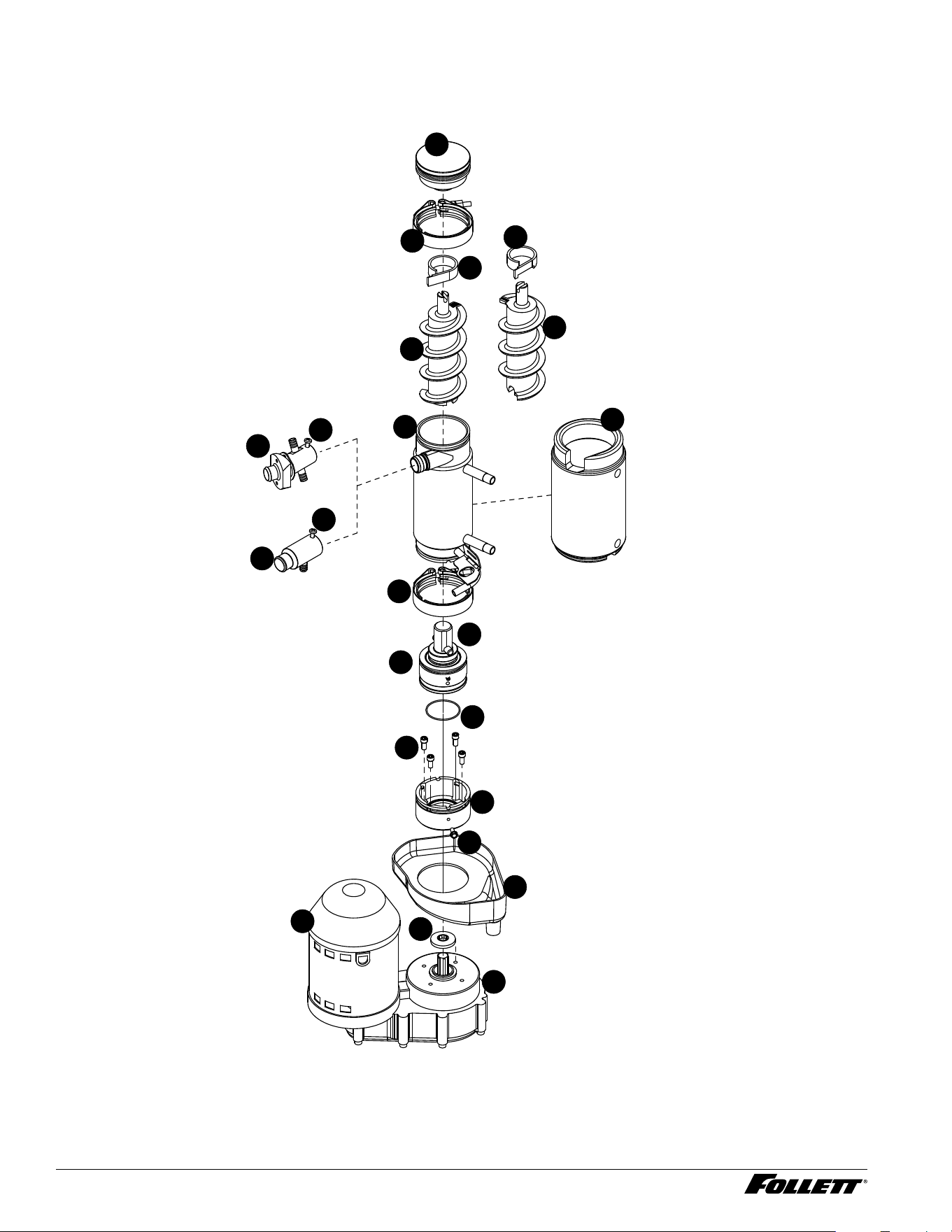
Replacement Parts
Evaporator Assembly
1
7
6
13
21
18
9
10
8
11
12
17
4
5
3
17
15
16
1
2
3a
4a
20
Integrated Icemaker R290 39
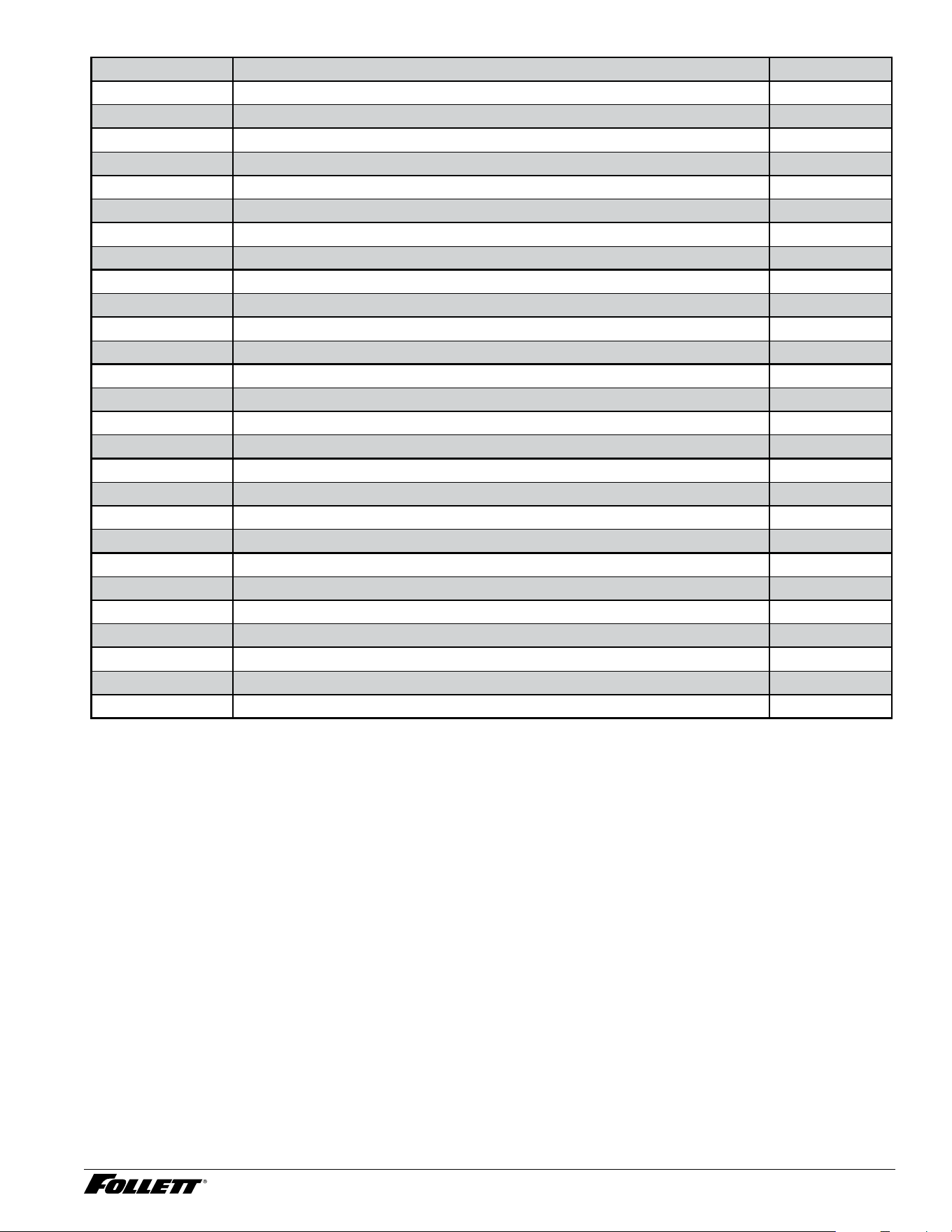
Reference # Description Part #
1 Coupling, vee-band, includes nut 502735
2 Bearing assembly, top 502736
3 Loop, ice compression, beveled 502110
3a Loop, ice compression, notched (Flaker component) 00124115
4 Auger 502737
4a Auger, with paddle (Flaker component) 00124123
5 Evaporator assembly (does not include insulation jacket) 01096205
6 O-ring, bearing housing 500496
7 Bearing assembly, bottom 502738
8 O-ring, mounting base 501063
9 Shield, condensate 500744
10 Screw, Allen 1/4 20 x 1/2 (set of 4) 501080
11 Mounting base, evaporator (includes 501063) 502733
12 Bolt, mounting base 502227
13 Gearbox & motor 115 V 502730
13 Gearbox & motor 220 V 60 Hz/230 V 50 Hz 502832
Not shown Mounting base, gearbox 01067693
15 Compression nozzle, Micro Chewblet, assembly 01092584
16 Compression nozzle, Flaker, assembly 01092592
17 Screw, compression nozzle mounting 00911743
18 Drain pan, evaporator 00181990
Not shown Grease 501111
19 Bracket, drain hose 01007087
20 Insulation jacket, evaporator 00946392
Not shown Relay, gearmotor 00142042
21 Cover, plastic 01012228
Not shown Insulation, compression nozzle 01092568
40 Integrated Icemaker R290
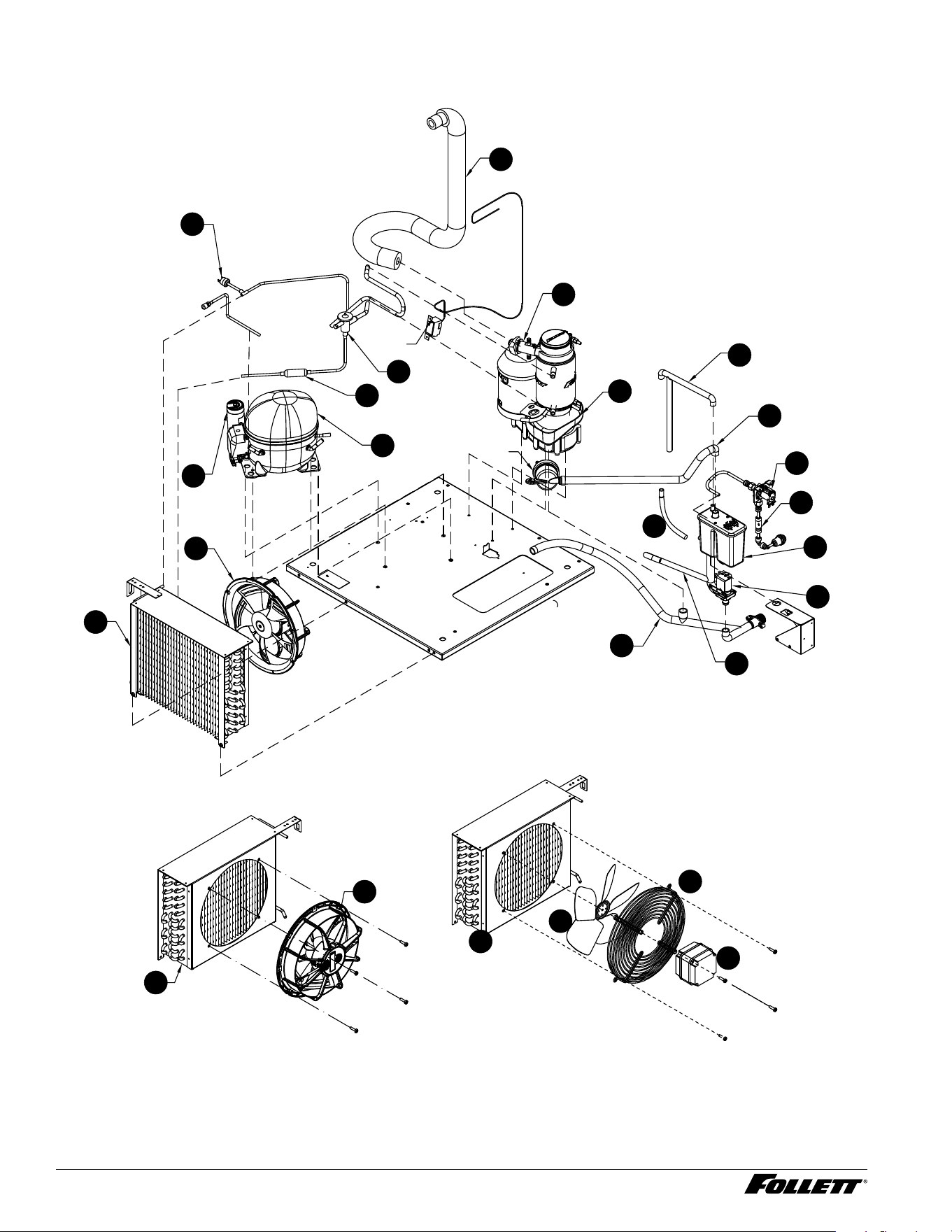
Components Assembly
5
6b
6c
6a
115 V
230 V
11
10
15
12
14
21
20
9
13
8
7
4
2
1
19
6
5
6
5
3
17
Integrated Icemaker R290 41
Reference # Description Part #
1 Compressor, 230 V 50 Hz 01458074
1 Compressor, 115 V 60 Hz 01458066
2 Filter, drier 01355452
3 Switch, high pressure 00117077
4 Valve, expansion 01440288
5 Condenser 01079433
6 Fan assembly, condenser 115 V 50/60 Hz 01076504
6a Fan motor, condenser 230 V 50/60 Hz 01292564
6b Fan cover, condenser 230 V 50/60 Hz 01292572
6c Fan blade, condenser 230 V 50/60 Hz 01292580
7 Compression Nozzle, Flaker, assembly 01092592
7 Compression Nozzle, Micro Chewblet, assembly 01092584
8 Pan, drain 00181990
9 Tube, sanitizer 01092865
10 Tube, water feed 01056225
11 Tube, drain line 01056241
12 Water reservoir assembly 01093517
13 Valve, water feed solenoid 230 V 50 Hz 00116848
13 Valve, water feed solenoid 115 V 01333707
14 Valve, check 01066166
15 Valve, purge 230 V 50 Hz 00991190
15 Valve, purge 115 V 00991216
16 Cup, cleaning 01065226
17 Tube, ice transport (includes insulation and clamp) 01079623
18 Bin thermostat 01383504
19 Capacitor, compressor run 115 V 60 Hz 01440650
19 Capacitor, compressor run 230 V 50 Hz 01458058
20 Tube, nozzle vent 01092857
21 Tube, nozzle to reservoir 01098862
Not shown Lid, water reservoir (includes screws, probes, elbow and gasket) 01099118
Not shown Gasket, water reservoir 00990978
Not shown Overload switch, compressor (230 V 50 Hz) 01458470
Not shown Overload switch, compressor (115 V 60 Hz) 01458462
Not shown Water inlet, push in 00976787
42 Integrated Icemaker R290
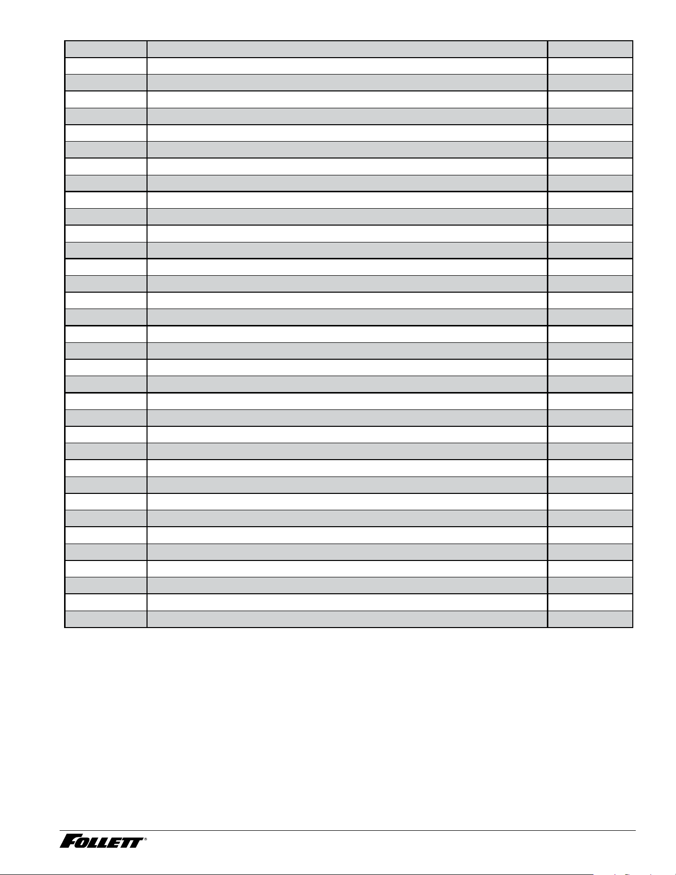
External Components
1
11
9
2
3
8
7
6
5
10
4
13
12
Reference # Description Part #
1 Grille, front cover 01079474
2 Frame, door assembly 01079482
3 Guide, door slide left 01079490
4 Guide, door slide right 01079508
5 Sliding doors 01079540
6 Roller, doors 01056407
7 Scoop 01056415
8 Holder, scoop 01056423
9 Filter, condenser 01058544
10 Cover, top 01032556
11 Cover, front stainless steel blend 01079532
12 Legs, 6" (150 mm) accessory (set of 4) 205440
13 Feet, leveling (each) 01066224
Integrated Icemaker R290 43
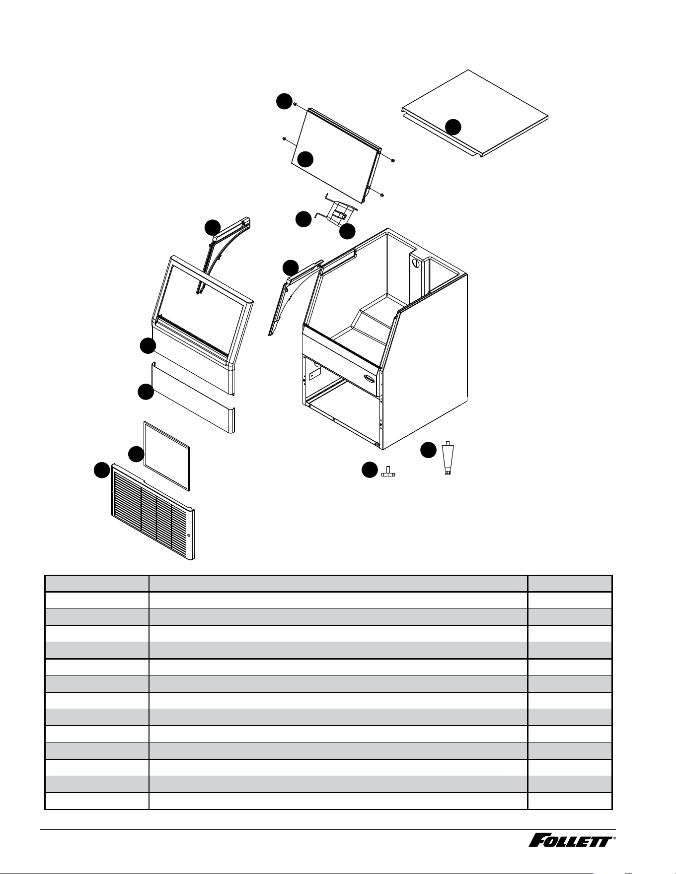
Electrical Box
3
7
11
2
12
1
5
13
14
15
4
8
9
10
6
Reference # Description Part #
1 Cover, includes thumbscrew 01079573
2 Main board 115 V (includes stand-offs) 01064708
2 Main board 230 V 50 Hz (includes stand-offs) 01092550
3 Label, LED 01016914
4 Capacitor, compressor start 230 V 50 Hz 01458041
4 Capacitor, compressor start 115 V 60 Hz 01440643
5 Relay, compressor start 230 V 50 Hz 01458033
5 Relay, compressor start 115 V 60 Hz 01440635
6 Stand-offs 115 V 00903005
Stand-offs 230 V 50 Hz 01066208
7 Switch, clean 01066539
8 Grommet 00177907
9 Inlet, power supply IEC 01115930
10 Frame, electric box 01061092
11 Switch, on/off 01086024
12 Thumbscrew, knurled 01082791
13
14
15
Not Shown Cord and plug 115 V 01078039
Not Shown Cord, 230 V 50 Hz 01066547
44 Integrated Icemaker R290
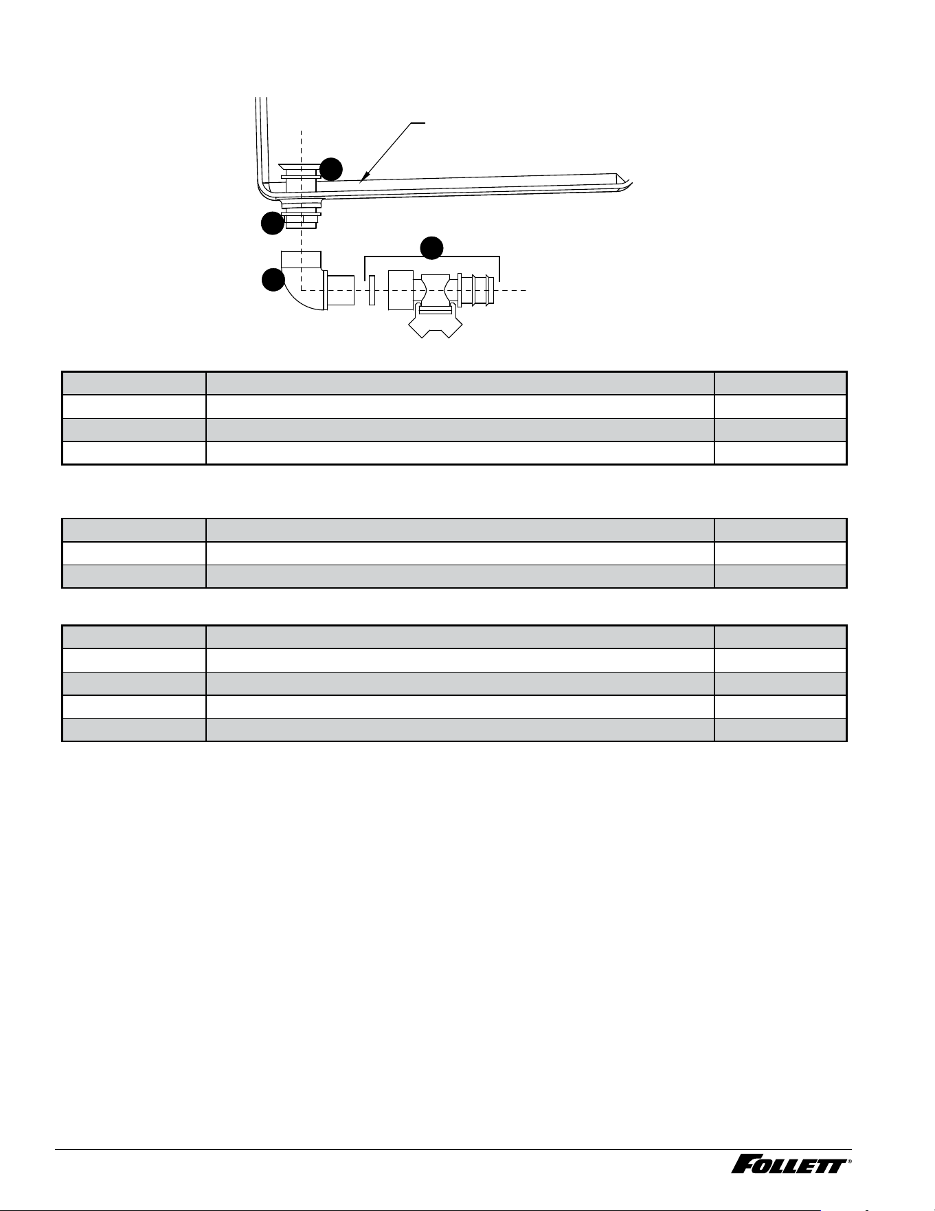
Bin Drain
ICE BIN
2
1
1
3
Reference # Description Part #
1 Bin drain tting 01066042
2 Elbow 3/4" 01066018
3 Bin drain valve (includes gasket) 01458025
Water Connections 220 V 60 Hz/230 V 50 Hz
Reference # Description Part #
Not shown 3/8" push-in x 1/2" BSP 01083211
Not shown 3/8" tubing x 3 m 208592
Drain Line Components 220 V 60 Hz/230 V 50 Hz
Reference # Description Part #
Not shown 3/4" drain elbow 01092519
Not shown 3/4" barbed thread 01092501
Not shown 3/4" tubing (25,3 mm x 3 m) 00949917
Not shown Clamp 01083278
Integrated Icemaker R290 45
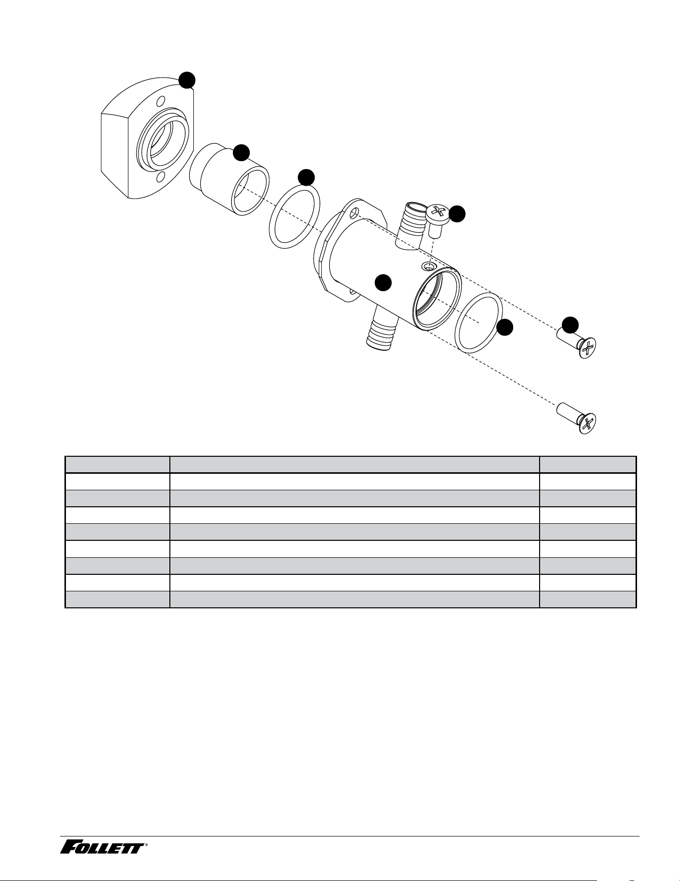
Micro Chewblet Nozzle
4
3
2
1
6
7
5
Reference # Description Part #
1 Ice breaker 01066794
2 Nozzle, compression 01066802
3 O-ring, 22 x 3 01081074
4 Screw, M5 x 10 00911743
5 Holder with clamp, nozzle 01073303
6 O-ring, 22 x 2 01081066
7 Screw, M5 x 16 00911750
Not shown Insulation, compression nozzle 01092568
46 Integrated Icemaker R290
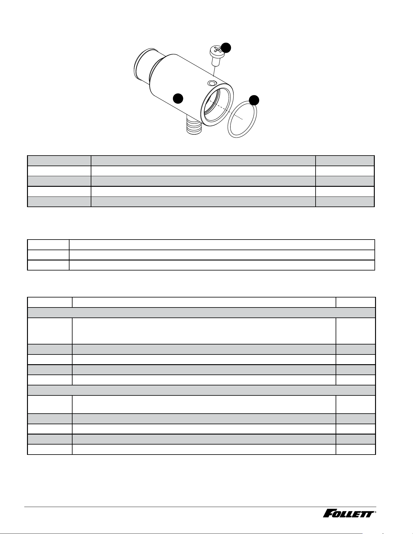
Flaker Nozzle
1
3
2
Reference # Description Part #
1 Nozzle, aker 01076876
2 O-ring, 22 x 2 01081066
3 Screw, M5 x 10 00911743
Not shown Insulation, compression nozzle 01092568
Icemaker Cleaner/Descaler
01149954 SafeCLEAN Plus, case of 6
01149962 SafeCLEAN Plus, case of 24
00131524 Sponge, sanitary, each
Water Treatment Accessories
Reference # Description Part #
Standard capacity lter system
Not shown Follett QC4-FL4S water lter system (includes FL4S primary cartridge and head,
coarse pre-lter and head, pressure gauge, ushing valve; assembled and installed on
mounting bracket), one per ice machine
00130229
Not shown Follett FL4S primary replacement cartridge 00130245
Not shown Water lter cartridge – primary, carton of 6 00954297
Not shown Everpure coarse pre-lter cartridge 00130211
Not shown Water pre-lter cartridge – pre-lter, carton of 12 00954305
Carbonless high capacity lter system
Not shown Carbonless high capacity water lter system (one per ice machine) – Horizon™ and
MaestroPlus series ice machines
01050442
Not shown Carbonless high capacity water lter cartridge – primary, single 01050426
Not shown Carbonless high capacity water lter cartridge – primary, carton of 6 01050434
Not shown Water pre-lter cartridge – pre-lter, single 00130211
Not shown Water pre-lter cartridge – pre-lter, carton of 12 00954305

Integrated Icemaker R290 47

01473883R01
© Follet Products, LLC 7/24
Micro Chewblet and SafeCLEAN Plus are trademarks of Follett Products, LLC.
Chewblet and Follett are registered trademarks of Follett Products, LLC, registered in US.
Follett Europe Polska Sp. z o.o.
Mokry Dwór 26 c • 83-021 Wiślina, Poland
+48 (58) 785-6140 • Fax +48 (58) 785-6159
www.folletteurope.com
801 Church Lane • Easton, PA 18040, USA
Toll free (877) 612-5086 • +1 (610) 252-7301
www.follettice.com