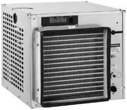
D414AS D414AT
P414A/W
Welcome to Follett
Follett equipment enjoys a well-deserved reputation for excellent performance, long-term reliability and outstanding
after-the-sale support. To ensure that this equipment delivers that same degree of service, review this guide carefully
before you begin your installation.
Should you have need technical help, please call our Technical Service group at (877) 612-5086 or (610) 252-7301.
Please have your model number, serial number and complete and detailed explanation of the problem when
contacting Technical Service.
Getting Started
After uncrating and removing all packing material. Inspect the equipment for concealed shipping damage. All freight
is to be inspected upon delivery. If visible signs of damage exist, please refuse delivery or sign your delivery receipt
"damaged." Follett Customer Service must be notied within 48 hours. Wherever possible, please include detailed
photos of the damage with the original packaging so that we may start the freight claim process.
Installation and Service Videos:
www.follettice.com/servicevideolibrary
01570225R00
801 Church Lane • Easton, PA 18040, USA
Toll free (877) 612-5086 • +1 (610) 252-7301
www.follettice.com
Installation, Operation and Service Manual
Please visit https://www.follettice.com/technicaldocuments
for the Operation and Service manual for your unit.
D414AT, D414AS, P414A/W
Ice Machines

2 D414A/W, R414A/W, D414A/W_F, P414A/W Ice Machines
Contents
Welcome to Follett. . . . . . . . . . . . . . . . . . . . . . . . . . . . . . . . . . . . . . . . . . . . . . . . . . . . . . . . . . . . . . . . . . . . . . . . . . . 1
Getting Started ........................................................................... 1
Specications .............................................................................. 5
Electrical ................................................................................ 5
Plumbing ................................................................................ 5
Ambient ................................................................................. 5
Water usage (water-cooled condenser only) .................................................... 5
Shipping weight .......................................................................... 5
R290 ice machine charge specications ....................................................... 5
Refrigeration pressure data ................................................................. 6
Compressor data ......................................................................... 6
Dimensions and clearances ................................................................. 7
Cleaning ................................................................................... 8
Weekly ................................................................................. 8
Monthly ................................................................................. 8
Semi-Annually (more often if conditions dictate) ................................................. 8
Service ................................................................................... 10
Ice machine Operation (all models) .......................................................... 10
The icemaking process .................................................................... 10
Water system ............................................................................11
Electrical system ......................................................................... 12
Electrical control system schematic .......................................................... 14
Electrical control system operation ........................................................... 15
Refrigeration system (all models) ............................................................ 30
Replacement parts ......................................................................... 34
Air-cooled skins assembly (D414A) .......................................................... 34
Water-cooled skins assembly (D414W) ....................................................... 35
Louvered docking station (D414A/W_T) ....................................................... 36
Electrical components .................................................................... 37
Evaporator ............................................................................. 38
Air-cooled ice machines ................................................................... 40
Water-cooled ice machines. . . . . . . . . . . . . . . . . . . . . . . . . . . . . . . . . . . . . . . . . . . . . . . . . . . . . . . . . . . . . . . . . 42
Replacement ice machine ordering matrix ..................................................... 45
WARNING! Risk of re or explosion. Flammable refrigerant used. Follow handling instruction
carefully. To be repaired only by trained service Personnel.
WARNING! Do not puncture Refrigerant Tubing. Do not use this product with ammable gases or
ammable solvents.
WARNING! Do not store ammable gases, ammable liquids or ammable solids in these units. Do not
use FLAME to check for gas leak.
WARNING! Do not under any circumstances try to modify or repair valves, regulator, connectors,
controls or any other appliance. Doing so creates the risk of a gas leak.
WARNING! Keep ventilaton openings clear of obstruction.
WARNING! Do not damage the refrigerant circuit.
WARNING! Connect to potable water supply only.
WARNING!
Installation
§ Read this manual thoroughly before operating, installing or performing maintenance on the equipment. Failure to follow
instructions in this manual can cause property damage, personal injury, or death.
§ The ice machine contains R290 (propane) refrigerant. R290 (propane) is ammable in concentrations of air between
approximately 2.1% and 9.5% by volume. R290 (propane) may burn if exposed to a heat source above 470 °C.
§ Because R290 is highly ammable, a combustible gas leak detector is required when servicing R290 systems.
§ This equipment contains high-voltage electricity and refrigerant charge. Installation and Service repairs are to be performed by
properly trained technicians aware of the dangers of dealing with high voltage electricity and refrigerant under pressure. The
technician must also be certied in proper refrigerant handling and servicing procedures.
§ All lockout and tag out procedures must be followed when working on this equipment.
§ A qualied person shall provide a readily accessible disconnect device incorporated into the xed wiring.
§ This appliance should be permanently connected by a qualied person in accordance with application codes.
§ If the supply cord is damaged, it must be replaced by the manufacturer, its service agent or similarly qualied persons in order to
avoid a hazard.
§ Do not tilt unit further than 30° off vertical during uncrating or installation.
§ This appliance is designed for commercial use.
§ This equipment is intended for indoor use only. Do not install or operate this equipment in outdoor areas.
§ Warranty does not cover exterior or outside installations.
§ To avoid a hazard due to instability of the appliance, it must be xed in accordance with the instructions.
§ Maintain all minimum clearances. DO NOT obstruct vents or openings.
§ This appliance is not suitable for installation in an area where a water jet could be used.
§ Connect to potable water supply only.
§ Follett recommends a Follett water lter system be installed in the ice machine inlet water line (standard capacity, high capacity,
carbonless high capacity).
§ We reserve the right to make product improvements at any time. Specications and design are subject to change without notice.
Usage
§ Read this manual thoroughly before operating, installing or performing maintenance on the equipment. Failure to follow
instructions in this manual can cause property damage, personal injury, or death.
§ User maintenance should not be done by children.
§ This appliance can be operated by children aged 8 years and above and persons with reduced physical, sensory, or mental
capabilities, or lack of experience and knowledge if they have been given supervision or instruction concerning use of the
appliance in a safe way and understand the hazards involved. Children should be supervised to ensure that they do not play with
the appliance.
§ If the supply cord is damaged, it must be replaced by the manufacturer, its service agent or similarly qualied persons in order to
avoid a hazard.
§ Routine adjustments and maintenance procedures outlined in this manual are not covered by the warranty.
D414A/W, R414A/W, D414A/W_F, P414A/W Ice Machines 3

4 D414A/W, R414A/W, D414A/W_F, P414A/W Ice Machines
§ Maintain all minimum clearances. DO NOT obstruct vents or openings.
§ This appliance must not be cleaned by a water jet.
§ Connect to potable water supply only.
§ Ice is food. Follow recommended cleaning instructions to maintain cleanliness of delivered ice.
§ Ice is slippery. Maintain counters and oors around dispenser in a clean and ice-free condition.
§ We reserve the right to make product improvements at any time. Specications and design are subject to change without notice.
Service
§ Read this manual thoroughly before operating, installing or performing maintenance on the equipment. Failure to follow
instructions in this manual can cause property damage, personal injury, or death.
§ Review Installation section.
§ This equipment contains high-voltage electricity and refrigerant charge. Installation and Service repairs are to be performed by
properly trained technicians aware of the dangers of dealing with high voltage electricity and refrigerant under pressure. The
technician must also be certied in proper refrigerant handling and servicing procedures.
§ To reduce risk of shock, disconnect power before servicing.
§ When servicing this equipment, be sure to lock the circuit breaker, and display an in-service notice.
§ Repair on R290 systems must always be done in a well-ventilated area.
§ If the supply cord is damaged, it must be replaced by the manufacturer, its service agent or similarly qualied persons in order to
avoid a hazard.
§ Only use parts recommended or provided by the manufacturer. Use of unapproved parts can be dangerous due to design
requirements to safely use R290 (propane).
§ Routine adjustments and maintenance procedures outlined in this manual are not covered by the warranty.
§ Maintain all minimum clearances. DO NOT obstruct vents or openings.
§ This appliance must not be cleaned by a water jet.
§ Connect to potable water supply only.
§ We reserve the right to make product improvements at any time. Specications and design are subject to change without notice.
Decommissioning and Dismantling
§ Read this manual thoroughly before operating, installing or performing maintenance on the equipment. Failure to follow
instructions in this manual can cause property damage, personal injury, or death.
§ Decommissioning and Dismantling are to be performed by properly trained technicians aware of the dangers of dealing with
high voltage electricity and refrigerant under pressure. The technician must also be certied in proper refrigerant handling
procedures for R290 (ammable) refrigerant.
§ Review Installation section.
§ Ensure area is being well-ventilated before Decommissioning and Dismantling of equipment using R290 (ammable) refrigerant.
§ When servicing this equipment, be sure to lock the circuit breaker, and display an in-service notice.
§ To reduce risk of shock, disconnect power before servicing.
§ Utilize and maintain good safety practices and follow all applicable local, state, and federal regulations for proper
decommissioning and disposal of the equipment.
§ Ensure all personal protective equipment is used during the entire process.
§ Ensure all necessary tools and equipment are available, including recovery equipment and cylinders.
§ All containers used for recovery must have proper labelling to ensure they can be used for R290 (ammable) refrigerant.
§ Before starting recovery, place refrigerants on scales. Do not overll containers more than 80% of volume, and do not exceed
working pressure of the container.
§ Before using a recovery machine, ensure that it is in satisfactory working order and that the electrical components are properly
sealed to prevent any type of ignition.
§ Recovered refrigerant shall not be added or used in another refrigerating system or mixed into another container.
§ If the compressor or compressor oils are removed, ensure it has been removed to an acceptable level so that ammable
refrigerant does not remain in the lubricant.
Disposal
§ Follow all applicable local, state, and federal regulations for proper disposal of the equipment.
§ All recovered refrigerant must be returned to an appropriate refrigerant supplier for proper disposal.
§ DO NOT dispose of your appliance with household waste.
Specications
Electrical
§ Each ice machine and dispenser requires a separate circuit with electrical disconnect within 10 ft (6 m).
§ Equipment ground required.
§ Standard electrical – 115 V, 60 Hz, 1 phase.
§ Connect to a dedicated 15A circuit.
§ Maximum ice machine amperage – 11A each.
§ Cord and plug provided on ice machine.
Plumbing
§ 3/8" FPT water inlet
§ 3/4" MPT drain
§ 3/8" FPT condenser inlet (water-cooled condenser only)
§ 3/8" FPT condenser drain (water-cooled condenser only)
Notes:
§ Slope to drain of 1/4" per foot (20 mm per 1 m run) with a 1/2" min. is recommended.
§ Water shut-off recommended within 10 feet (3 m), drain to be hard piped and insulated.
§ Separate drains for ice machine and condenser. To prevent back ow, do NOT connect drains.
§ Follett recommends a Follett water lter system be installed in the ice machine inlet water line (standard capacity,
high capacity, carbonless high capacity).
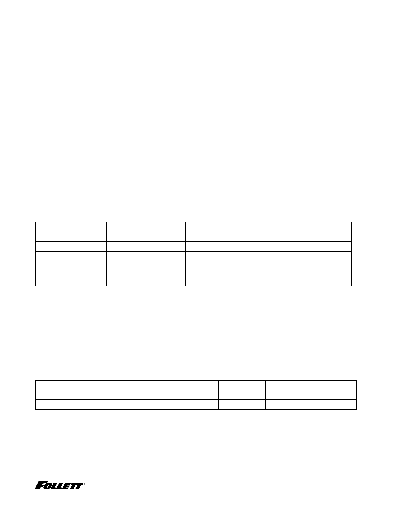
Ambient
Air temperature* 100 F/38 C max. 50 F/10 C min. (best performance below 80 F/27 C)
Water temperature
†
90 F/32 C max. 45 F/10 C min. (best performance below 70 F/21 C)
Water pressure 70 psi max. (482 kPA) 10 psi min. (68 kPA)
Condenser water
temperature
90 F/32.2 C max. 45 F/7.2 C min
Condenser water
pressure
125 psi (862 kPA) max. 10 psi (68 kPA) min.
*
Ambient air temperature is measured at the air-cooled condenser coil inlet.
†
Ambient water temperature is measured in the ice machine reservoir.
Water usage (water-cooled condenser only)
§ 0.25 gpm @ 50 F (10 C)
§ 0.5 gpm @ 70 F (21 C)
§ 1.25 gpm @ 90 F (32 C)
Shipping weight
§ 160 lb (73 kg)
R290 ice machine charge specications
Model Charge Refrigerant type
D414A, P414A (air-cooled) 3.49 oz (99 g) R290
P414W (water-cooled) 1.83 oz (52 g) R290
D414A/W, R414A/W, D414A/W_F, P414A/W Ice Machines 5
Refrigeration pressure data
§ Water regulating valve is factory set at 300 (±10) PSIG head pressure.
§ Readings within 10% of table values should be considered normal.
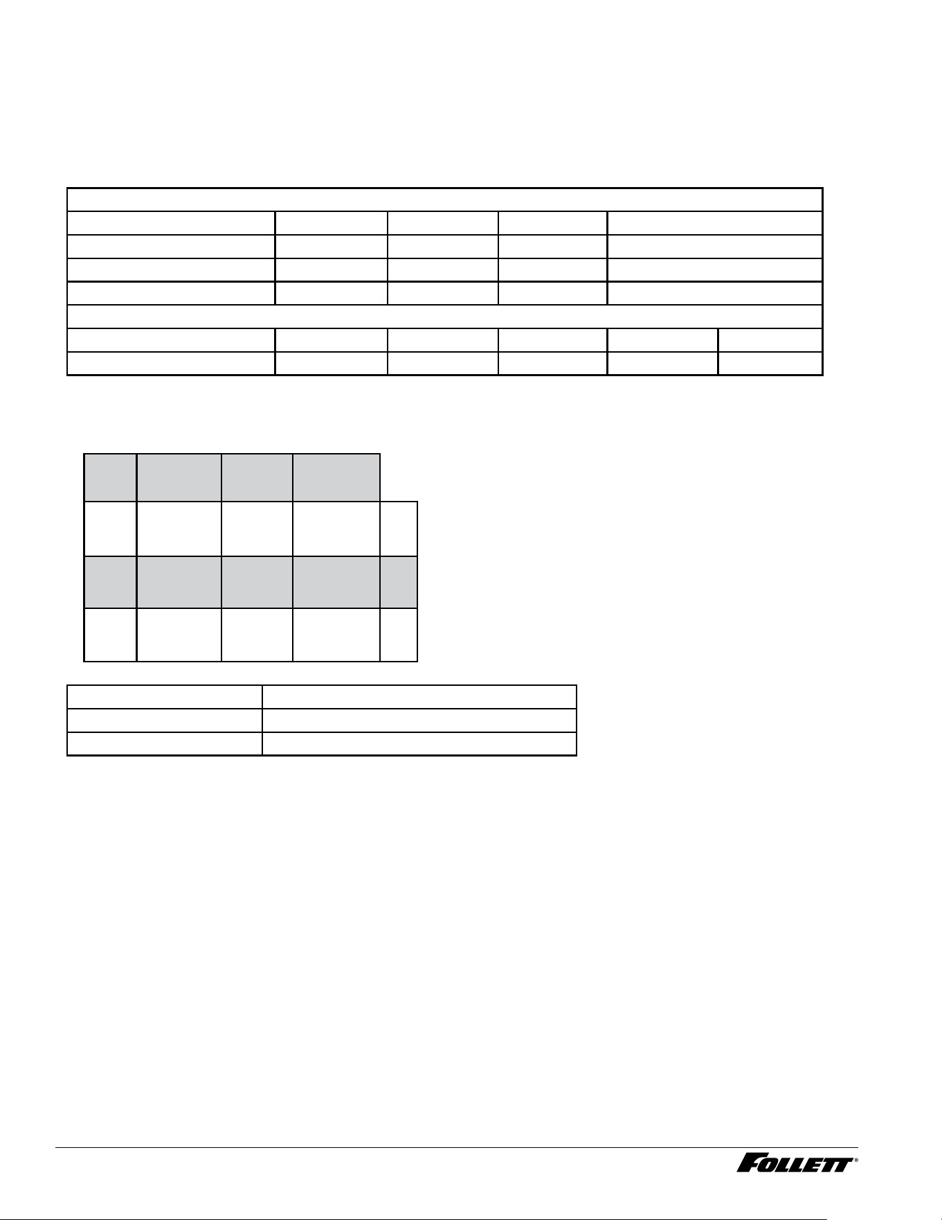
Compressor data
Locked rotor amps 48A
Compressor current draw
Air-cooled
Ambient air temperature 60 F/15.6 C 70 F/21.1 C 80 F/26.7 C 90 F/32.2 C
Amperage 5.4A 5.6A 6.0A 6.1A
High-side pressure (psi) 140 150 174 206
Low-side pressure (psi) 15 17 21 26
Water-cooled
Water temperature at oat 50 F/10 C 60 F/15.6 C 70 F/21.1 C 80 F/26.7 C 90 F/32.2 C
5.6A 5.6A 5.7A 5.8A 5.8A
Water-Cooled ice machine refrigeration pressure
Discharge pressure/suction pressure
Condenser Water Temperature F/C
Inlet Water Temperature F/C
F/C 50/10 70/21 90/32
50/10 200/22 200/24 207/25 psi
70/21 200/22 200/24 207/25 psi
90/32 200/22 200/24 207/25 psi
Gearmotor data PSC (permanent split capacitor)
Gearmotor current 0.8A–0.9A (nominal)
Locked rotor amps 7A–14A (temperature dependent)
6 D414A/W, R414A/W, D414A/W_F, P414A/W Ice Machines
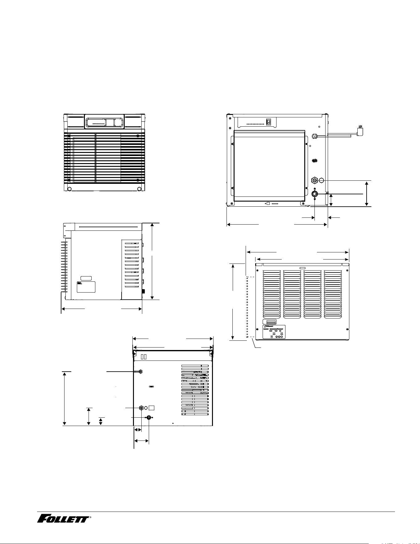
Side view — air-cooled
20.75" (52.7 cm)
22.75" (57.8 cm)
17.00"
(43.2 cm)
RIDE model air-cooled units only
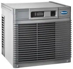
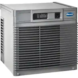
Front view — top mount
D414AT
D414AS
Side view — top mount
22.49" (57.1 cm)
21.29" (54.1 cm)
22.69" (57.6 cm)
22.46" (57.1 cm)
Back view — top mount
A
B
C
Front view — air-cooled
4.81"
(12.0 cm)
2.31" (5.7 cm)
2.5" (6.4 cm)
C
D
A
B
18.88" (48 cm)
2.32"
(5.9 cm)
4.40" (11.2 cm)
15.22" (38.7 cm)
5.03" (12.8 cm)
2.34" (6 cm)
Dimensions and clearances
§ Entire front of ice machine must be clear of obstructions/connections to allow removal.
§ 12" (30.5 cm) clearance above ice machine for service.
§ 6" (15.3 cm) minimum clearance between exhaust side of ice machine and any adjacent equipment.
§ 18" (45.7 cm) minimum, 10 ft (3 m) maximum clearance between discharge and air
intake grilles.
A – 3/4" MPT drain
B – 3/8" FPT water inlet
C – Electrical cord
D – 3/8" FPT condenser inlet
E – 3/8" FPT condenser drain
F – Bin signal connection (DO NOT APPLY VOLTAGE!)
D414A/W, R414A/W, D414A/W_F, P414A/W Ice Machines 7
Cleaning
Follett ice machines and dispensers, and their associated cleaning and sanitizing procedures, are designed for
use with potable water sources. The presence, or suspected presence, of infectious agents may call for additional
measures, including the replacement of components and more comprehensive disinfection measures. Follett
recommends that these cleaning and sanitizing procedures be reviewed with the appropriate infectious agent subject
matter experts to assure complete remediation.
Periodic cleaning of Follett’s ice machine system is required to ensure peak performance and delivery of clean,
sanitary ice. The recommended cleaning procedures that follow should be performed at least as frequently as
recommended and more often if environmental conditions dictate.
Cleaning of the condenser can usually be performed by facility personnel. Cleaning of the ice machine system
should be performed by your facility’s trained maintenance staff or a Follett authorized service agent. Regardless of
who performs the cleaning, it is the operator’s responsibility to see that this cleaning is performed according to the
schedule below. Service problems resulting from lack of preventive maintenance will not be covered under the Follett
warranty.
Recommended cleaning intervals*
Maestro Plus Frequency
Drain Line weekly
Drain Pan/Drip Pan weekly
Exterior, Water Station Tube as needed
Condenser monthly (air-cooled only)
Ice Machine semi-annually
Transport Tube semi-annually
* Ice machine must be cleaned prior to start-up.
Weekly
The exterior may be cleaned with a stainless cleaner such as 3M™ Stainless Steel Cleaner & Polish or equivalent.
Monthly
Condenser (air-cooled ice machine only)
1. Use a vacuum cleaner or stiff brush to carefully clean condenser coils of lint and debris to ensure optimal
performance.
2. When reinstalling counter panels in front of RIDE
®
model ice machines, be sure that ventilation louvers line
up with condenser air duct.
Semi-Annually (more often if conditions dictate)
§ A cleaning procedure should always include both the ice machine and bin/dispenser.
§ Icemaking system can be cleaned in place.
Cleaning Tool Checklist
§ (1) 1.5 gallon (or larger) plastic bucket
§ (2) clean cloths
§ Sanitary gloves
§ Safety glasses
§ SafeCLEAN™ Plus ice machine cleaner
§ (2) SaniSponge™ (P/N 00131524 - single sponge)
8 D414A/W, R414A/W, D414A/W_F, P414A/W Ice Machines
CAUTION!
§ Wear rubber gloves and safety goggles (or face shield) when handling SafeCLEAN Plus solution.
§ Use only Follett approved cleaners.
§ Do not use solvents, abrasive cleaners, metal scrapers or sharp objects to clean any part of the dispenser.
SafeCLEAN Plus Solution: Follow the directions on the SafeCLEAN Plus packaging to mix 1 gal. (3.8 L) of Follett
SafeCLEAN Plus solution. Use 100 F (38 C) water.
Cleaning Procedure
Note: Check drains and drain cup to ensure they are open and owing freely.
1. If ice machine was running recently, ensure that the evaporator is completely free of ice before proceeding.
If there is ice in the evaporator, complete steps 2-8 using only hot water to remove the ice, then begin
Cleaning Procedure again.
2. Remove front or top cover.
3. Disconnect bin signal cable from ice machine electrical box.
4. Press CLEAN switch. The MAINTENANCE light will turn on and the machine will ll and drain three times.
Wait for the LOW WATER light to turn on.
5. Remove water reservoir drain tube from the evaporator drain cup bracket and lift tube to higher level than
reservoir.
6. Remove lid from cleaning cup and ll (about 1 quart) until SafeCLEAN Plus solution completely lls the
reservoir. Place lid back on cup.
7. CLEANER FULL light will turn on and machine will start cleaning cycle then rinse three times; this process
takes approximately 15 minutes.
8. When machine is nished cleaning, the MAINTENANCE light will turn off.
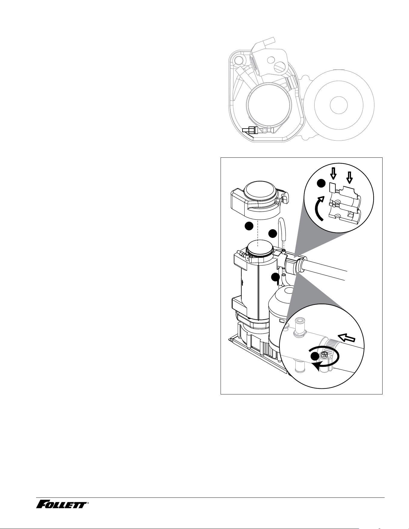
9. Remove top bearing insulation. Loosen Phillips-head screw on nozzle connected to evaporator. Remove
nozzle from evaporator side only, leave other side of nozzle connected to transport tube.
10. Soak both Sani-Sponges in remaining SafeCLEAN Plus solution .
11. Insert both sponges soaked in SafeCLEAN Plus solution into nozzle then insert one at a time.
12. Replace nozzle onto evaporator and tighten screw. Ensure drain is connected to reservoir and vent tubes
are connected to evaporator drain pan. Replace top bearing insulation.
13. Lower water reservoir drain tube back to evaporator drain bracket.
14. Reconnect bin signal cable. Wait for ice to push sponges through transport tube.
15. Collect sponges from ice storage bin.
16. Replace front or top cover.
1 7. After 10 minutes, dispense all ice and discard.
18. Clean the dispenser/bin.
Exterior Cabinet
Clean stainless steel panels with stainless steel cleaner.
D414A/W, R414A/W, D414A/W_F, P414A/W Ice Machines 9
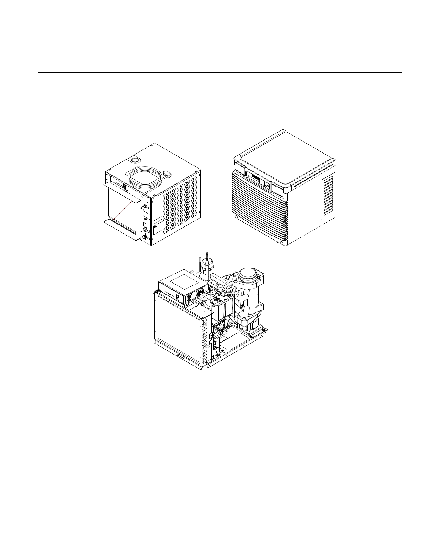
Service
Ice machine Operation (all models)
Follett’s ice machine consists of four distinct functional systems:
§ Harvesting system
§ Water system
§ Electrical control system
§ Refrigeration system
These four systems work together to accomplish the production and harvesting of ice. A problem in any one of these
systems will result in improper operation of the entire ice production cycle. When troubleshooting the ice machine, it is
important to analyze the entire system operation to determine which system is not functioning properly, then pinpoint
the component within that system that is malfunctioning. Determine what corrective action must be taken before
making any adjustments or replacing any components.
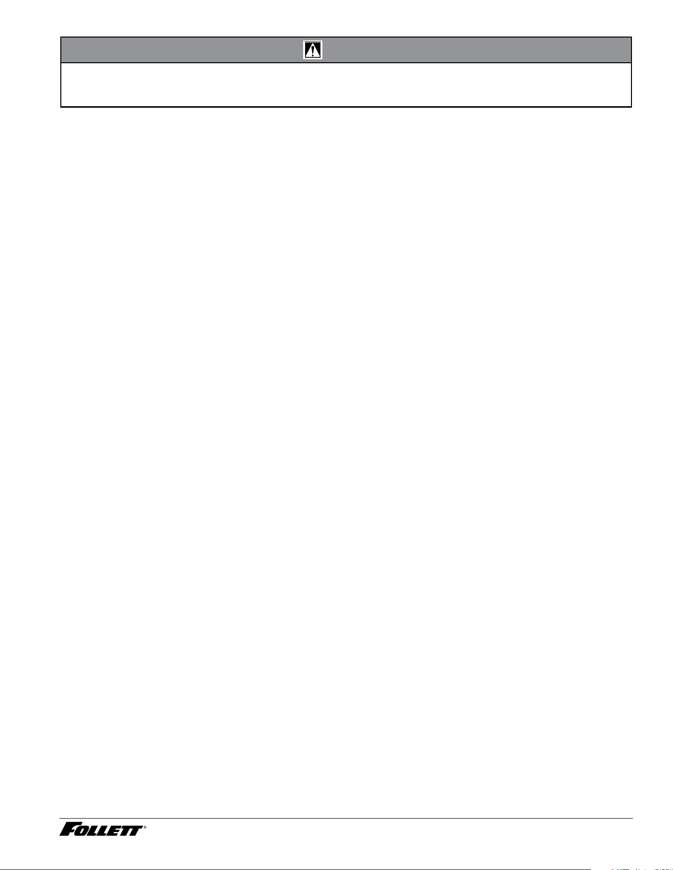
The icemaking process
The Maestro Plus ice machine uses a stainless steel jacketed evaporator and operates on a continuous freezing
cycle. Water is supplied to the evaporator from the water reservoir where the water level is controlled by conductivity
probes.
When the ice machine is running, a layer
of ice forms on the interior surface of the
evaporator. This ice is continuously removed
by a slowly rotating (12RPM) auger. The
auger carries the ice upward into the cavity
formed by the top bearing housing and the
compression loop, where it is compressed to
remove excess water. When the ice reaches
the desired hardness it rotates within the
cavity and is forced through a discharge
port and compression nozzle and into the
ice transport tube. The discharge tube and
compression nozzle are slightly restricted to
further compress the ice and produce the
desired hardness.
A solid state control board located in the
electrical box of the ice machine controls
the normal operation of the ice machine
and monitors gearmotor torque. This control
board will shut down the ice machine should
an over-torque condition occur. It is very
important that you familiarize yourself with
the operational sequences detailed in this
manual before attempting to service the ice
machine.
water
inlet
auger
compression nozzle
ice transport tube
evaporator
port
10 D414A/W, R414A/W, D414A/W_F, P414A/W Ice Machines
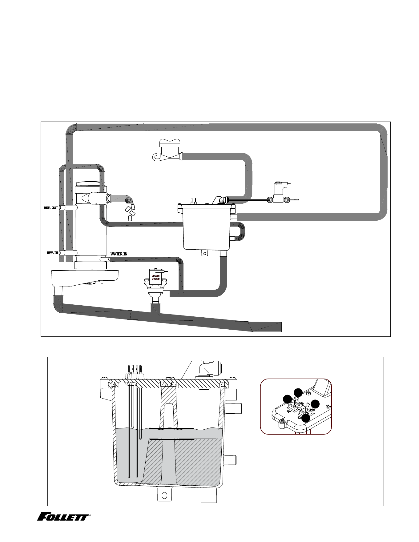
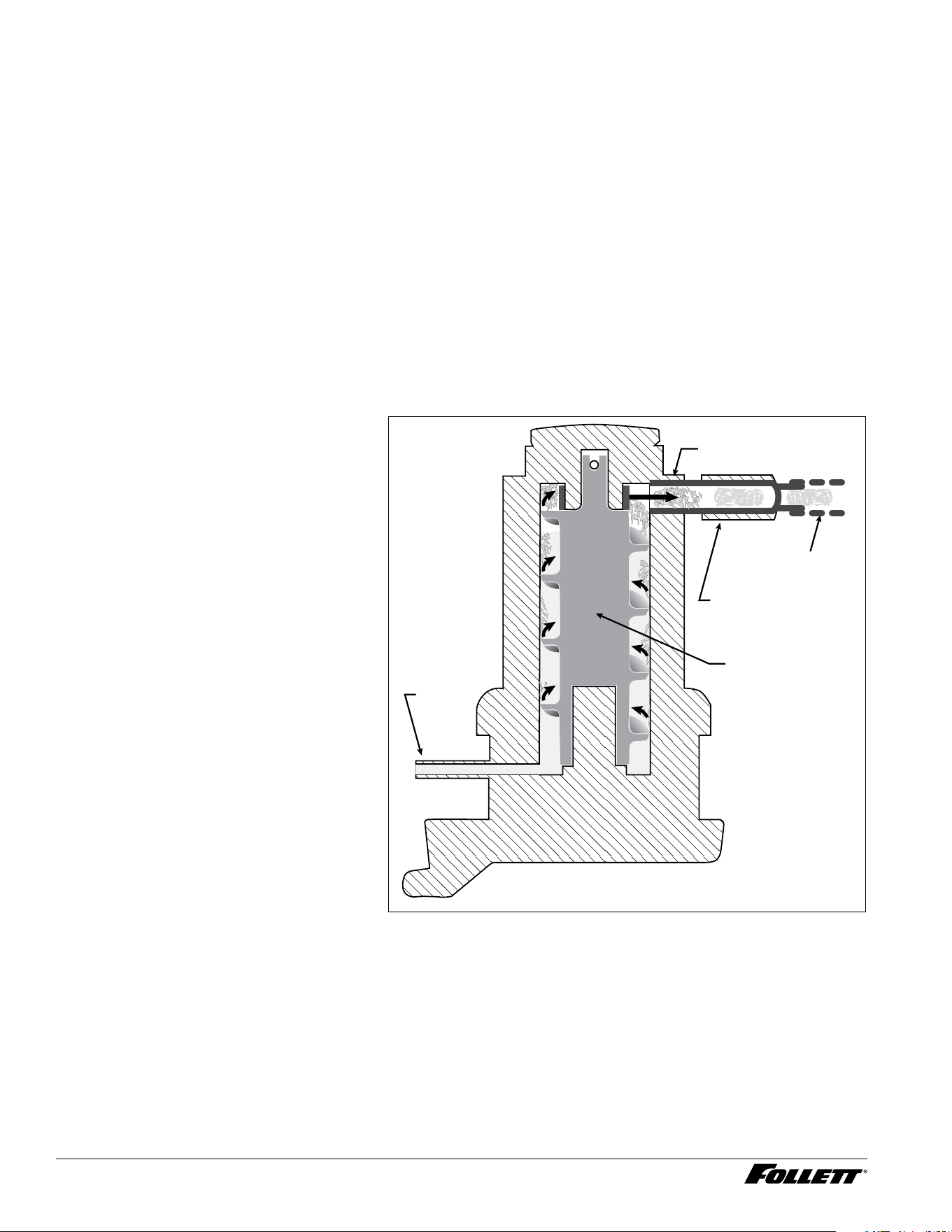
Water system
The water level in the evaporator is controlled by a ll solenoid (Fig 1) and level detecting sensors. Water sensing
rods (Fig. 2) extend down into the reservoir at the end of the evaporator assembly. The system works via electrical
conductivity as follows:
One of the longest probes is a common. When water is between any of the other probes and the common, the
PC board will sense the activation. During normal operation, the water level rises and falls between the Normal
High and Normal Low sensors. As water is consumed to make ice, the level will fall until the Normal Low sensor is
exposed, triggering the water feed solenoid on. Water will ll until the Normal High sensor is activated.
Note: The potable water dissolved solids content must be greater than 10 ppm for the water control system to
function properly. If using reverse osmosis water ltration system, ensure T.D.S level is greater than 10 ppm.
Fig. 1 Water system diagram
CLEANING CUP
WATER SUPPLY
3/8" FPT, 45-90 F (7-32 C)
10-70 PSI (69-483 KPA)
RESERVOIR FILL
SOLENOID
WASTE WATER DRAIN
3/4" FPT
WATER
RESERVOIR
EVAPORATOR
ICE
NOZZLE
DRAIN PAN
VENT
DRAIN
Fig. 2 Water level diagram
A ALARM LOW (RED)
B COMMON (BLACK)
C NORMAL HIGH (ORANGE)
D NORMAL LOW (YELLOW)
B
A
C
D
B
A
C
D
NORMAL OPERATING RANGE
D414A/W, R414A/W, D414A/W_F, P414A/W Ice Machines 11
12 D414A/W, R414A/W, D414A/W_F, P414A/W Ice Machines
Electrical system
ATTENTION!
To prevent circuit breaker overload, wait 15 minutes before restarting this unit. This allows the compressor
to equalize and the evaporator to thaw.
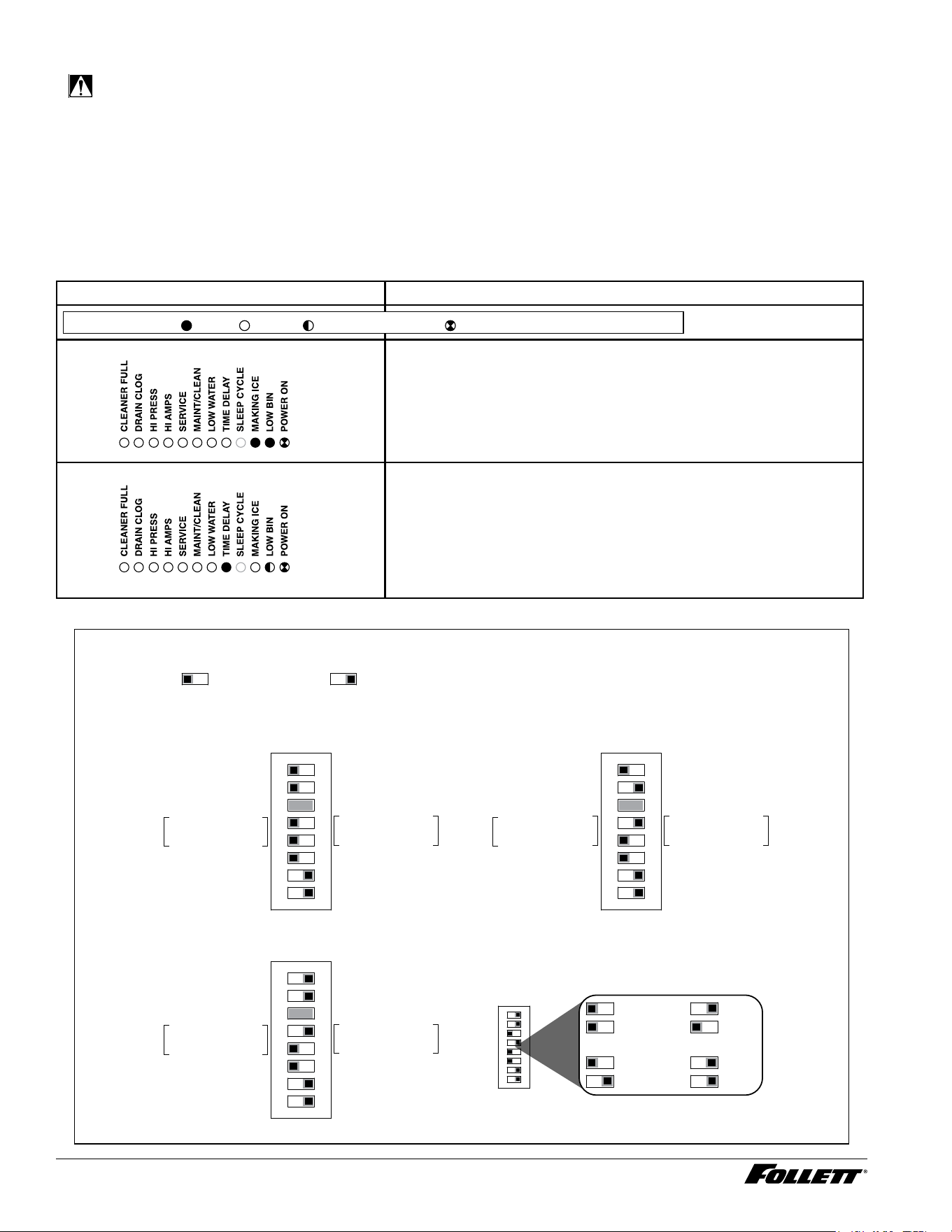
Normal control board operation
The PC board indicator lights provide all the information necessary to determine the machine's status. Green
indicator lights generally represent “go” or normal operation; yellow indicators represent normal off conditions; red
indicators generally represent alarm conditions, some of which will lock the machine off.
A ashing green light labeled POWER indicates power to the machine. All other normal operation status indicators
are covered as follows:
Ice machine disposition Operating conditions
FLASHINGON or OFF
Legend:
OFFON
1. Ice machine is making ice. 1. Normal running.
2. Ice machine is not making ice.
2. Normal time delay. When the bin lls with ice, the LOW BIN
light goes out momentarily and the refrigeration and auger
drive systems immediately shut down. (Note: The fan motor
will continue to run for 10 minutes to cool condenser) The TIME
DELAY light comes on, initiating the time delay period. When
the time delay expires, the machine will restart provided that the
LOW BIN light is on.
DIP Switch Settings
Sleep cycle dispense duration
OFF ON
1 2 3 4 5 6 7 8
4 5 4 5
4 5 4 5
35 s
15 s
5 s
60 s
OFF POSITION ON POSITION
Bin level timer on
Sleep cycle enabled
Lever*
Sleep cycle
dispense duration
60 min. time delay
Flush enabled
Maint. timer OFF
OFF ON
Bin level timer off
Sleep cycle disabled
SensorSAFE*
Sleep cycle
dispense duration
20 min. time delay
Flush disabled
Maint. timer ON
1 2 3 4 5 6 7 8
MUST be set to off
Sleep cycle enabled
Lever/Not used
Sleep cycle
dispense duration
60 min. time delay
Flush enabled
Maint. timer OFF
OFF ON
MUST be set to off
Sleep cycle disabled
SensorSAFE/Not used
Sleep cycle
dispense duration
20 min. time delay
Flush disabled
Maint. timer ON
1 2 3 4 5 6 7 8
D414AT, D414AS
Integrated Icemaker (all models)
Symphony Plus 110FB only
MUST be set to off
Sleep cycle enabled
Lever*
Sleep cycle
dispense duration
60 min. time delay
Flush enabled
Maint. timer OFF
OFF ON
MUST be set to off
Sleep cycle disabled
SensorSAFE*
Sleep cycle
dispense duration
20 min. time delay
Flush disabled
Maint. timer ON
1 2 3 4 5 6 7 8
Symphony Plus 12/25/50 CI, HI, or FB; E12CI
R290 Units Only
* Set according to application.

D414A/W, R414A/W, D414A/W_F, P414A/W Ice Machines 13
Relay/triac output indication
Each relay on the board has an indicator light associated with its output. For example, when the relay for the water
feed solenoid is energized, the adjacent indicator light glows green.
Flushing logic
Off cycle: At the completion of off-cycle time delay, the machine checks for a cumulative one (1) hour of ice making
time since the last off-cycle ush. If the cumulative ice making time exceeds one (1) hour, the machine will open
the drain valve for 60 seconds to drain the evaporator in its entirety. It will then rell with water, ush again and rell,
and begin making ice. If the ice making time is less than 1 hour, the machine will start and begin making ice without
draining the evaporator.
Error faults
The Maestro Plus PC board monitors various operating parameters including high pressure, auger gearmotor
amperage limits, clogged drain, and low water alarm conditions. There are two types of errors namely “hard” or “soft”.
A hard error is one that shuts the machine off and will not allow restart until the reset button is pressed. Even cycling
power will not reset a hard error. A soft error can either be automatically reset should the condition rectify, or if power
is cycled. Should an error occur, consult the troubleshooting guide in this manual or a Follett service technician.
Soft errors:
Note: For all soft errors, the ice machine will remain off for 1 hour.
LO WATER: During operation, the water level cycles between the normal low and normal high sensors. Should the
water be shut off to a running machine, a soft error will occur. The error sequence is as follows: During operation,
the water level falls to the normal low sensor, and when it does the water feed solenoid is energized. If water is not
detected at the normal low sensor within 10 seconds, a soft error will occur. The machine will shut down and TIME
DELAY and LOW WATER LEDs will be lit. After time delay, the solenoid will energize and remain energized until the
water level is sufficient for restart.
HI PRESSURE: Should the refrigeration pressure rise above 425 psi, the machine will shut down and the TIME
DELAY and HIGH PRESSURE will be illuminated. After the time delay, and if the pressure has fallen back below the
reset point of 295 psi, the machine will restart and the TIME DELAY and HIGH PRESSURE will clear.
HI AMPS: The PC board monitors the amperage of the auger motor. Should the gear motor experience current draw
above the allowable 3A limit or no current draw (0A), the machine will shut down and the TIME DELAY and HI AMP
will be illuminated. After the time delay the machine will restart and the TIME DELAY and HI AMP will clear.
Hard error:
HI AMPS: If a second hi-amp error occurs within 1 hour of the initial hi-amp error, the ice machine will shut off and
the reset on the board must be pressed to clear the error. If a second hi-amp has occurred, the HI AMP LED only will
be illuminated.
SERVICE: The drain clog sensor, located in the evaporator drain pan will detect the presence of water just below the
top edge of the pan. If water does not properly ow out of the internal or external drain lines it will backup into the
drain pan (especially during a self-ushing purge cycle). Pressing the reset button will restart the ice machine.
14 D414A/W, R414A/W, D414A/W_F, P414A/W Ice Machines
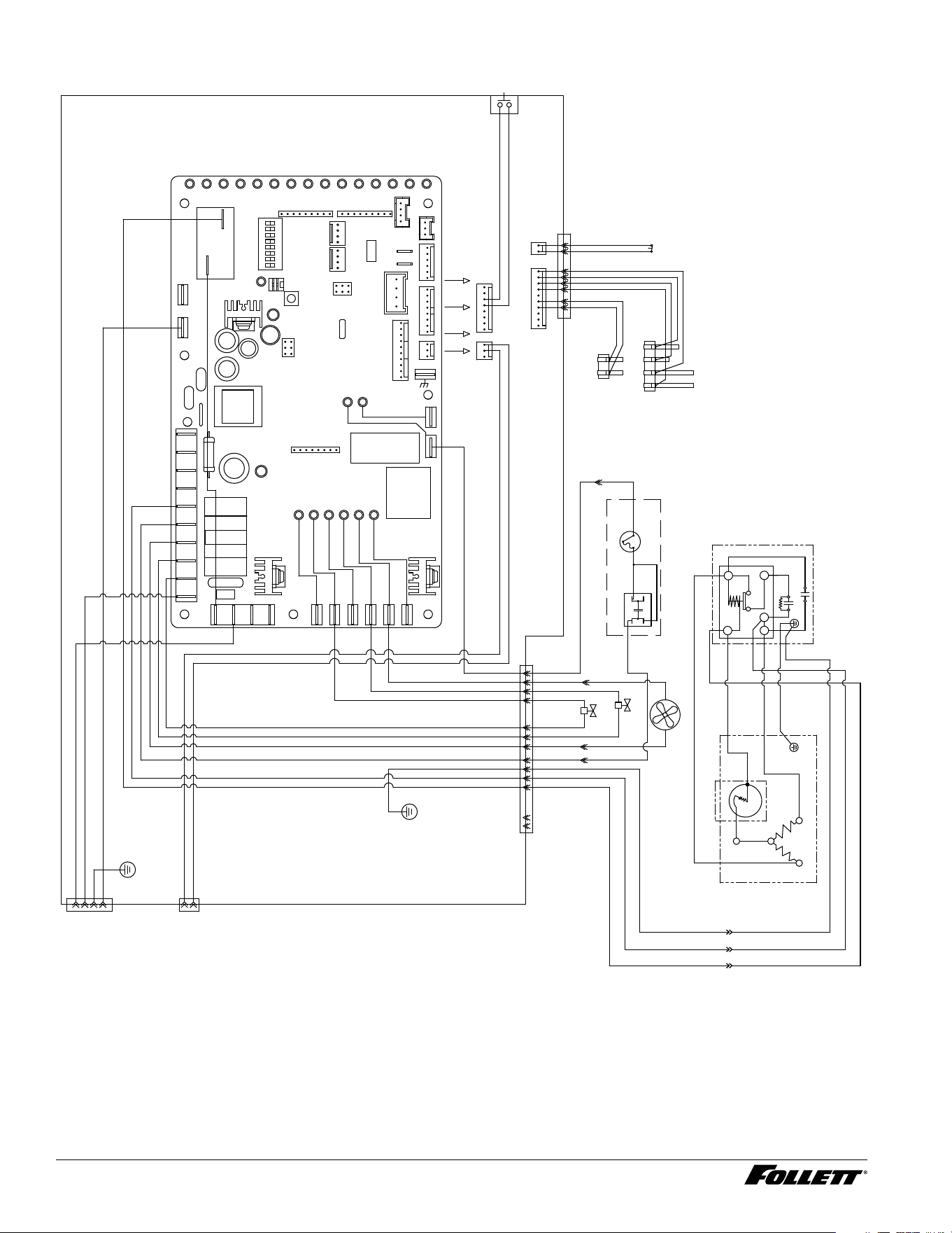
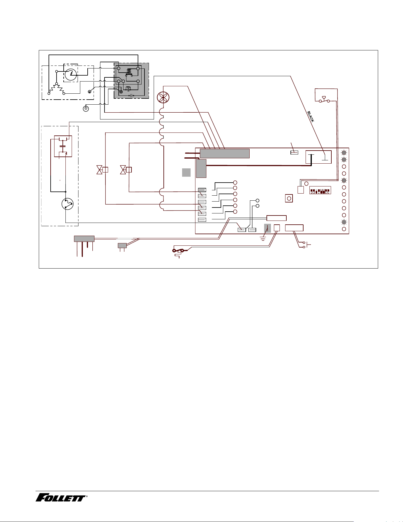
Electrical control system schematic
WATER LEVELS
P17
BIN
P12
CLEAN SAFE
P11
POWER
LOW BIN
MAKING ICE
SLEEP CYCLE
TIME DELAY
LOW WATER
MAINTENANCE
SERVICE
HI AMPS
HI PRESSURE
CLEANER FULL
HI PRS
P14
P
BLACK #51
GRN-YEL #24
WHITE #25
BLACK #26
FAN
RED #16
WHITE #35
WHITE #13
BROWN #14
BLACK 36
BLUE #07
BLACK #51
WHITE #52
1 2 3
GREEN #53
BLACK #51
WHITE #52
GREEN #53
#15
#13
WHITE
DRAIN CLOG
BLACK
BLUE
BLUE #07
PSC MOTOR
YELLOW
BLACK
T.O.L.
WHITE
COMPRESSOR
ELECTRICAL
BOX
4
1
2
5
4
1
3
RED
BLACK 51
WHITE 52
GRN/YEL 53
GRND
SCREW
BLACK
Cs
Cr
C1
#20 #19
2
WHITE #05
#52#05#35#13
WHITE #05
WHITE #35
WHITE #13
RED #16
BROWN #14
BLACK 36
COMPRESSOR MODELS
OPTIONAL IN CERTAIN
WHITE #15
WHITE #15
#15
P6
ICE DISP
P21
P20
P19
P3
P22
FS
WD
Drain
Fan
Spare
L1 L1L1
P1
COMPRESSOR
D16
K1
N N N N N N N N
P2
N
ICE AUX
P15
WATER AUX
P16
AUGER
P5
D37
P4
D18
MODEL SELECT
S1
ON
1 1 1 1 1 1 1 1
HI PRS
RESET
P14
S2
D9
D8
D5
D4
D3
D2
D15
D14
D13
D12
D11
D10
D1
D7
D6
P18
WATER LEVELS
P17
BIN
P12
RS485
P11
P8
P13
SERIAL COMM
P10
RS485 UI
P7
CN4 CN3
CN2
K3
CURRENT SENS
T2
1
P9
MISO
SCK
RESET
UCC
MOSI
GND
T1
BLACK 01
BLACK #23 BLACK #23
RESERVOIR
WATER SENSOR
MAINT.
CLEAN
HIGH
PRESS
A B C D
BLACK
YELLOW
ORANGE
RED
BIN
CONTACT
CLOSURE
L1
L2/N
DISP
FEED VALVE
DRAIN VALVE
DRAIN CLOG
SENSOR
BLACK
VIOLET
CAPACITOR
c
s
R
BLACK
YELLOW
GND
D414A/W, R414A/W, D414A/W_F, P414A/W Ice Machines 15
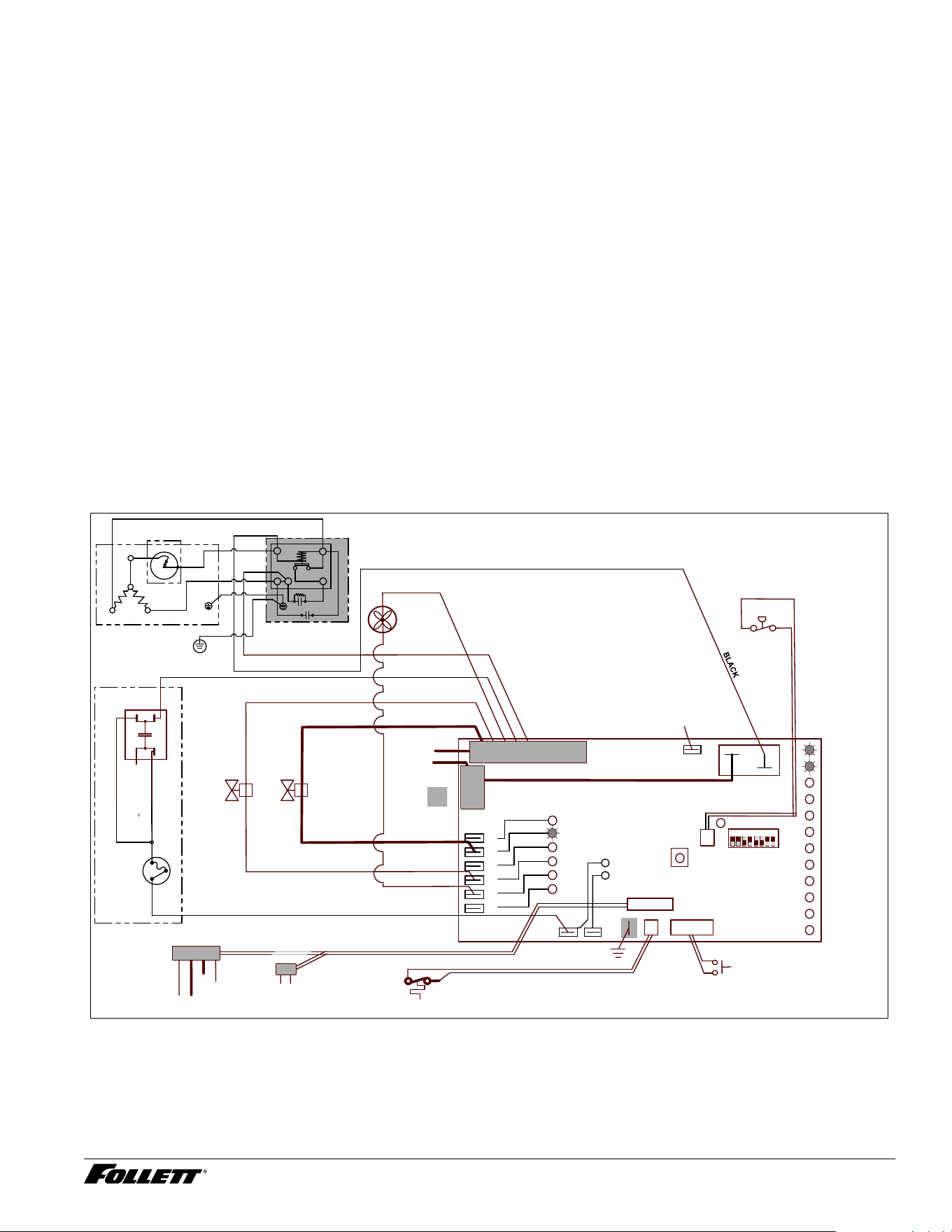
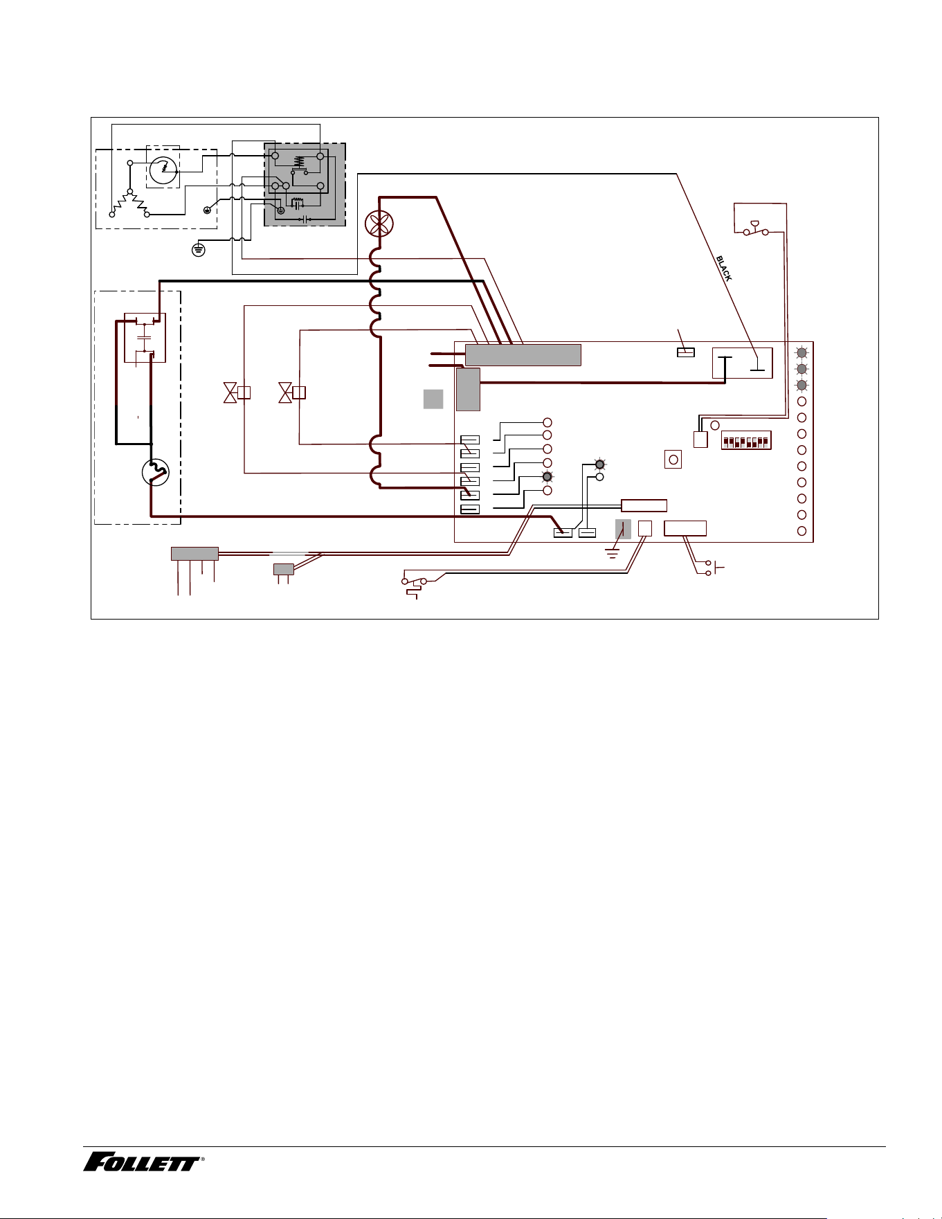
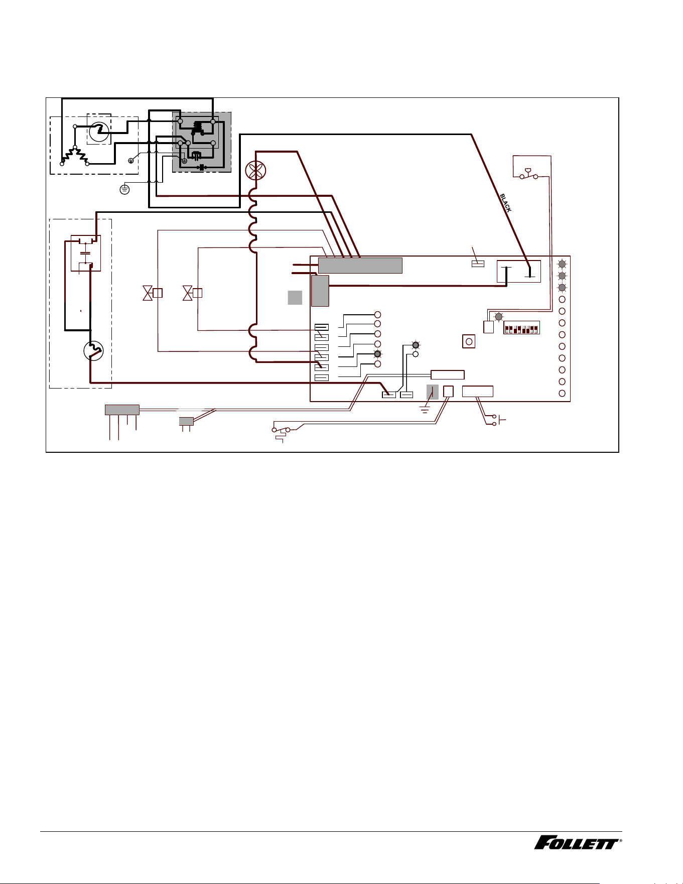
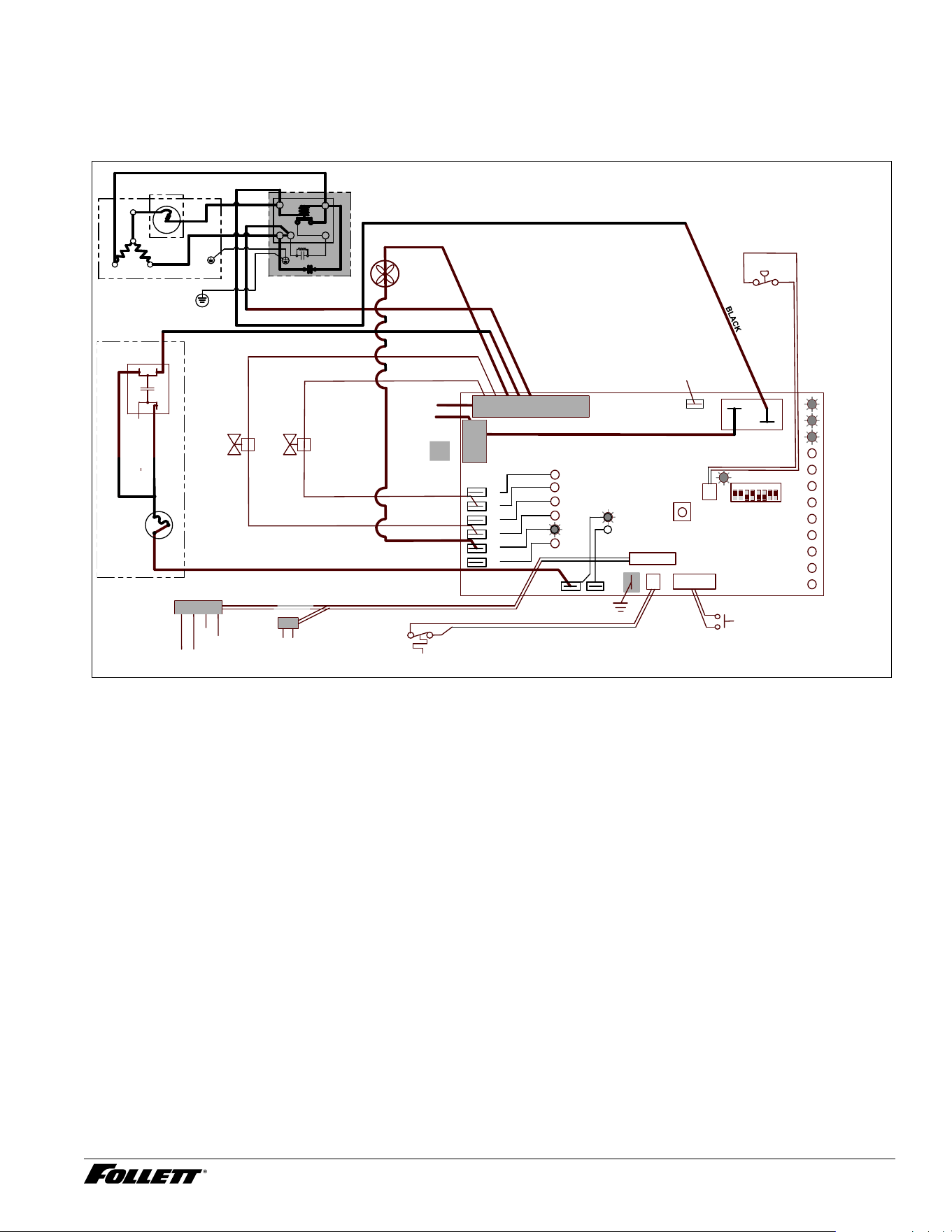
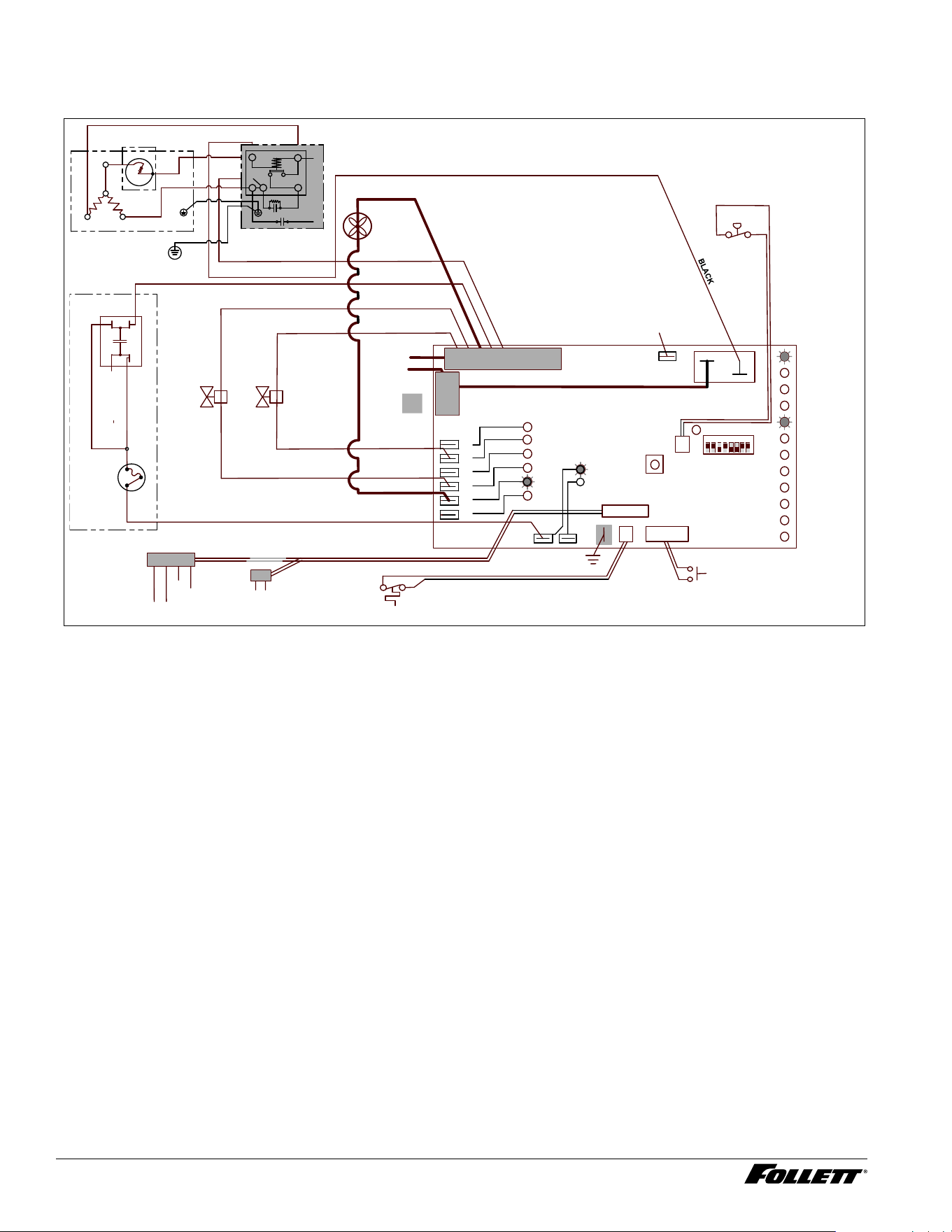
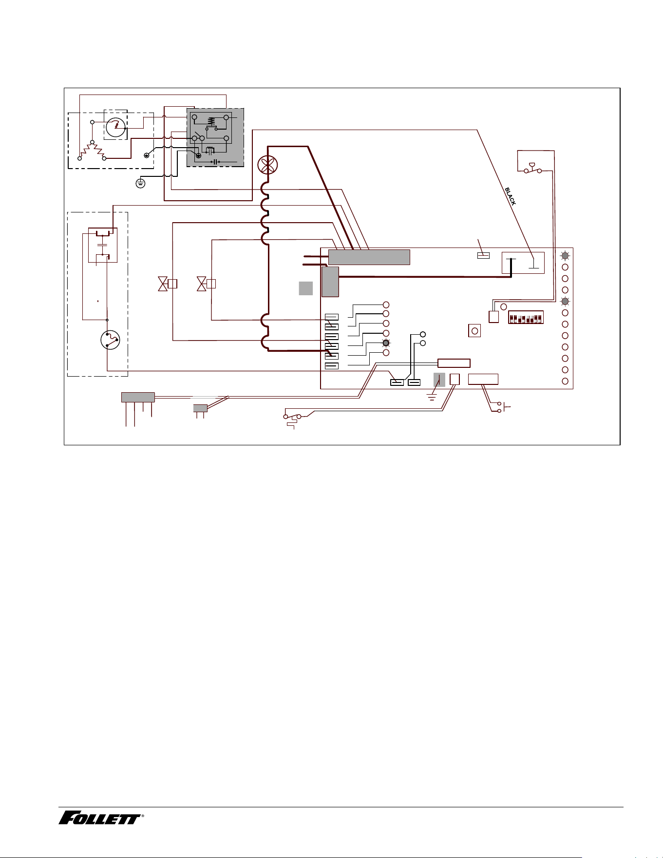
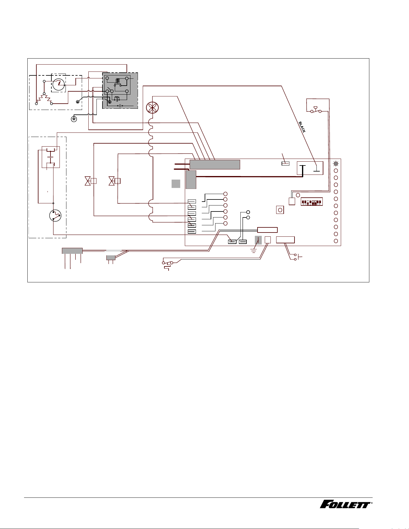
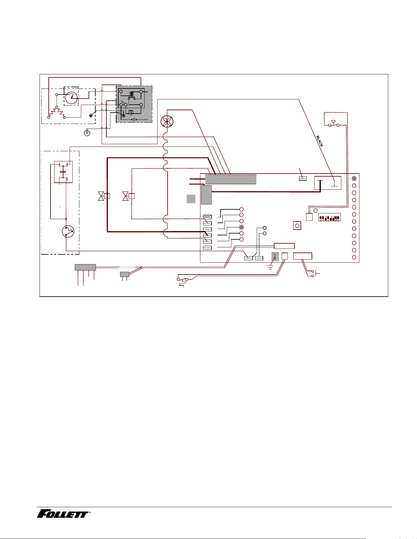
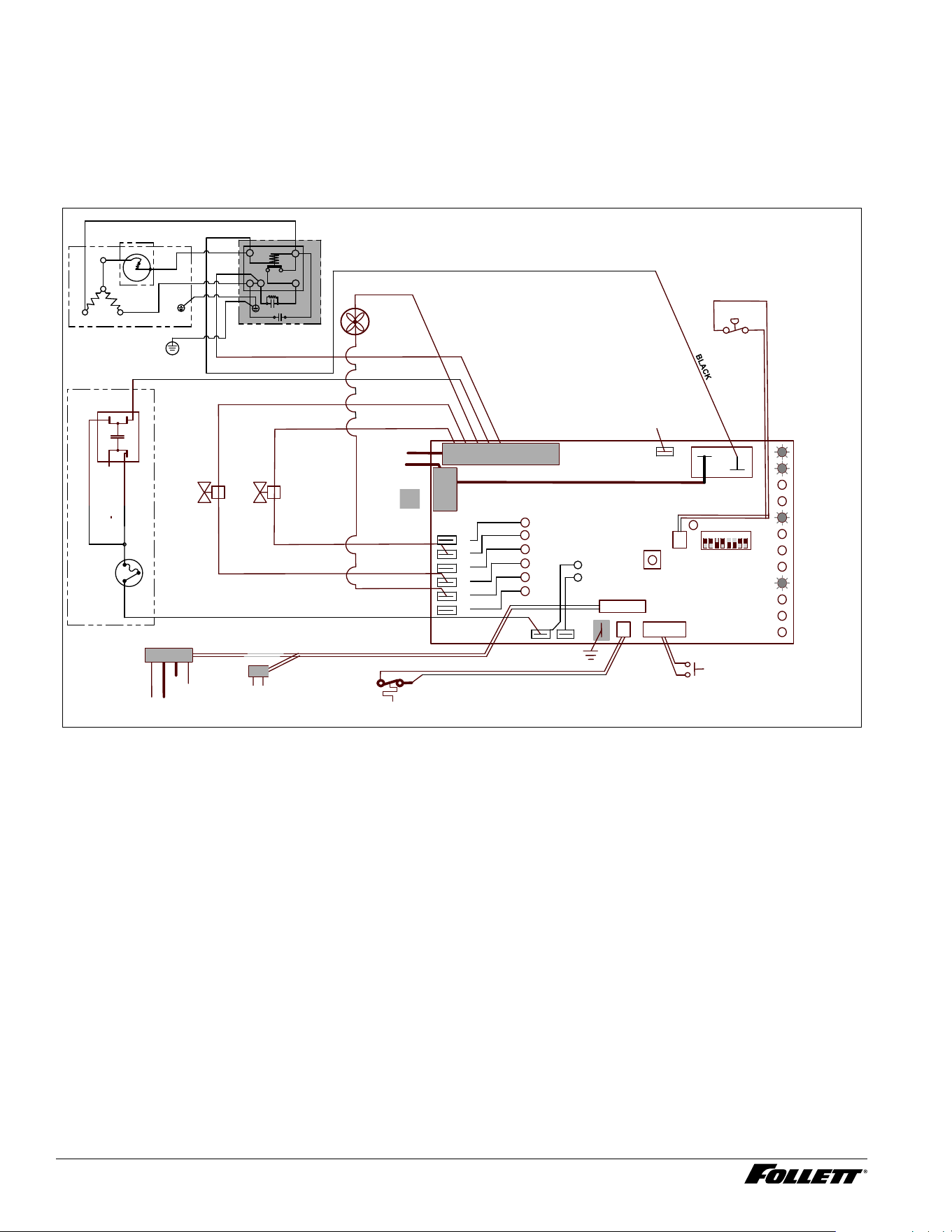
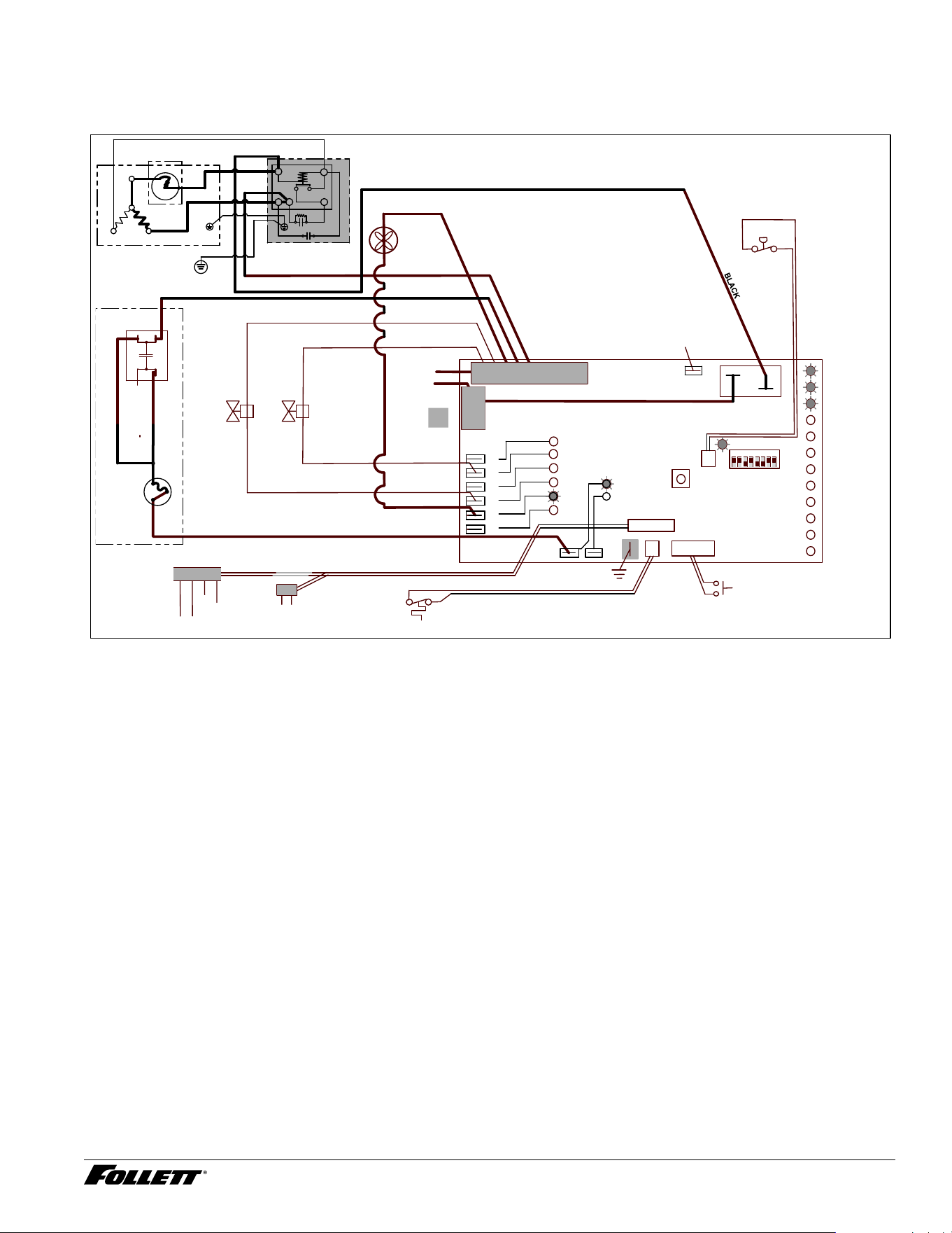
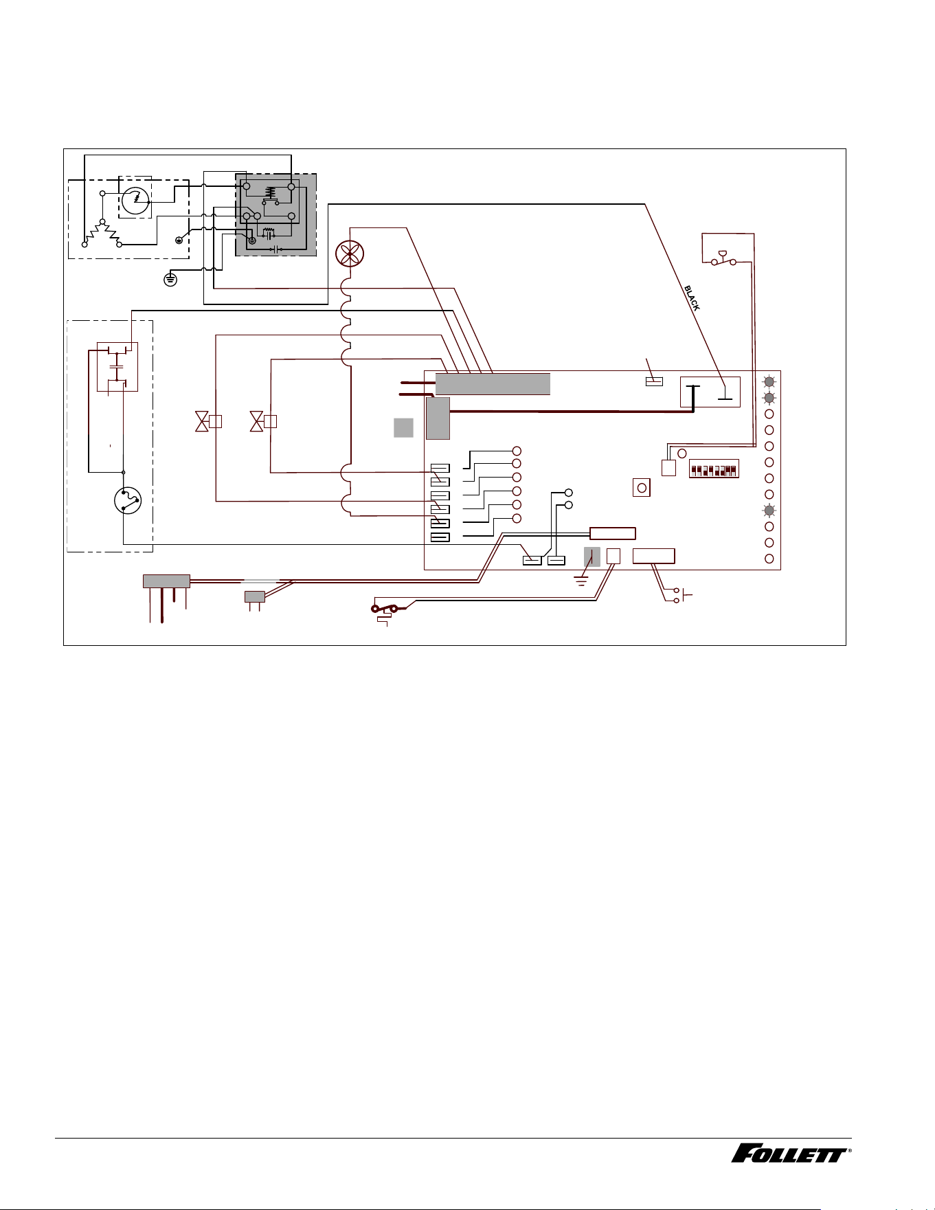
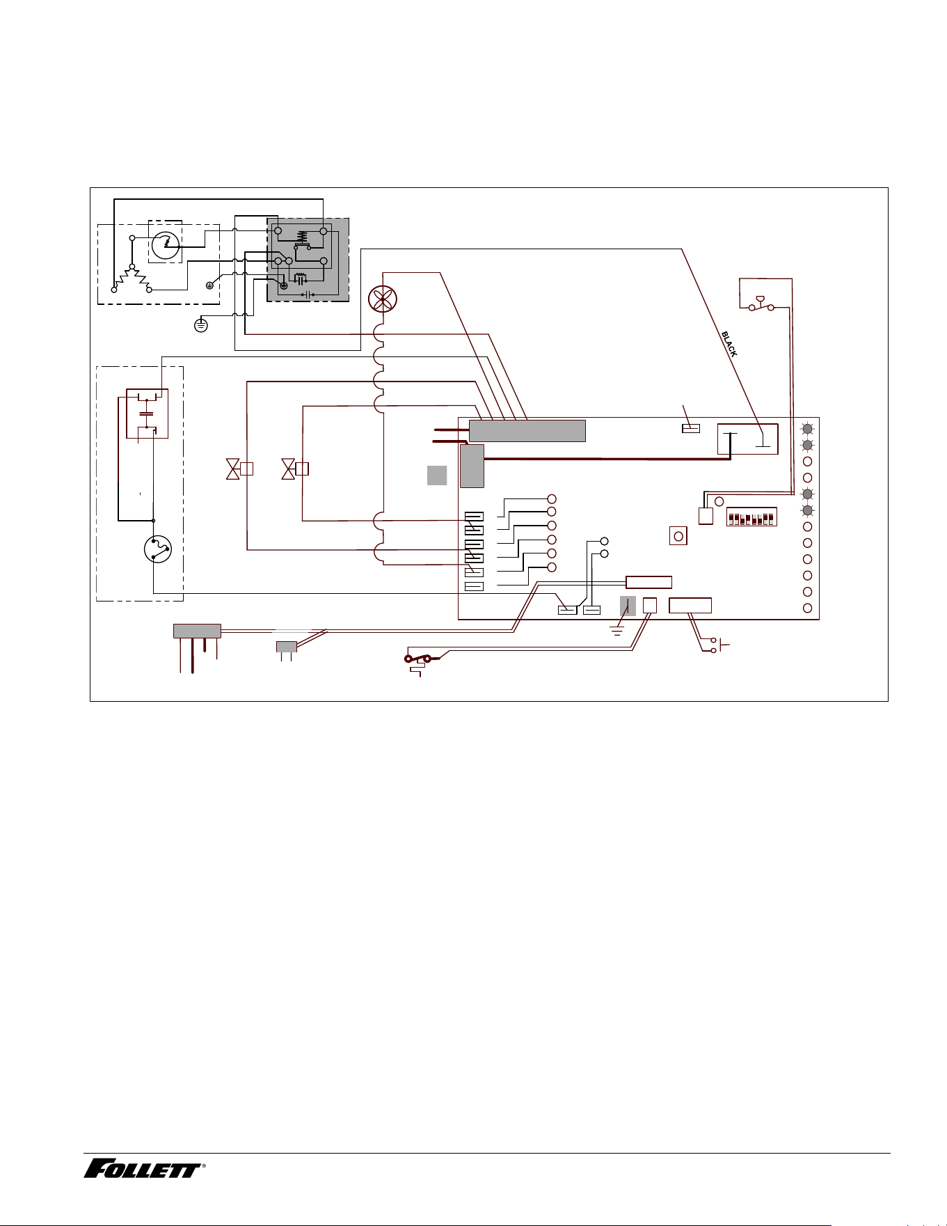
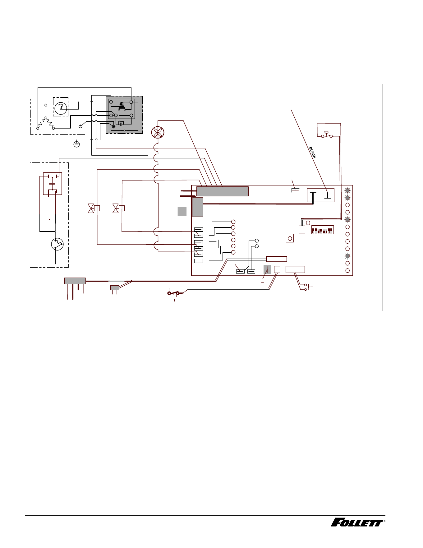
Electrical control system operation
The P414A/W, D414A/W_S and R414A/W wiring diagrams which follow illustrate the circuitry of Follett ice
machines used with ice dispensers. Both normal operation of the ice machine (Stages 1–6) and non-normal
diagnostic sequences showing torque-out (Stages 7–10) for use in troubleshooting ice machine problems are
shown.
Circuitry notes
When the ice machine is used with a dispenser it receives power from the main power supply. Disconnect the
power source before performing service. When performing electrical service, always use a meter to determine
whether or not the components being serviced are energized.
§ High pressure cutout opens at 425 PSI and closes at 287 PSI (auto reset).
§ The bin signal input to the control board in the 414A/W ice machine must only be initiated by contact closure.
Do not supply power. To run the ice machine in the workshop, use the bin signal jumper (P/N 01069095).
Note: The operation stage descriptions that follow are based on the unit containing the split-phase gear
motor.
Normal operation – Stage 1
Power is supplied to L1 of the control board, the POWER LED light begins ashing. The ice level bin thermostat in
the dispenser is closed and calling for ice, supplying contact closure to the control board. The LOW BIN LED will
be on. The control board will now go through the start-up sequence. The board checks the water sensors (located
in the reservoir) for continuity between the common probe (B) and the high probe (C). If continuity is not sensed,
the water ll valve (P21) is energized.
MAINTENANCE
LOW WATER
TIME DELAY
SLEEP CYCLE
MAKING ICE
LOW BIN
POWER
SERVICE
HI AMPS
HI PRESSURE
DRAIN CLOG
CLEANER FULL
High
Pressure
Switch
Gearmotor
L2/N
L1
Fan
A B C D
Water Sensors
RESET
Fill
Valve
Drain
Valve
Bin T-Stat
Clean Switch
Drain Clog Sensor
P6
P21
P20
P19
P3
P22
P4
AUGER
WATER LEVELS
BIN
P11
HI PRS
WHITE
BLACK
BROWN
BLUE
RED
COMPRESSOR
1 2 3 4 5 6 7 8
BLACK
N
P15
Ice Dispense Input
Capacitor
BLACK
YELLOW
NO CONNECT
L1
WHITE
WHITE
WHITE
WHITE
BLACK
Cs
Cr
1
5
2
4
4
P5
T.O.L.
VIOLET
BLACK
RED
BLACK
ORANGE
YELLOW
c
s
R
Compressor
Electrical Box
Optional in Certain
Compressor Models
Compressor
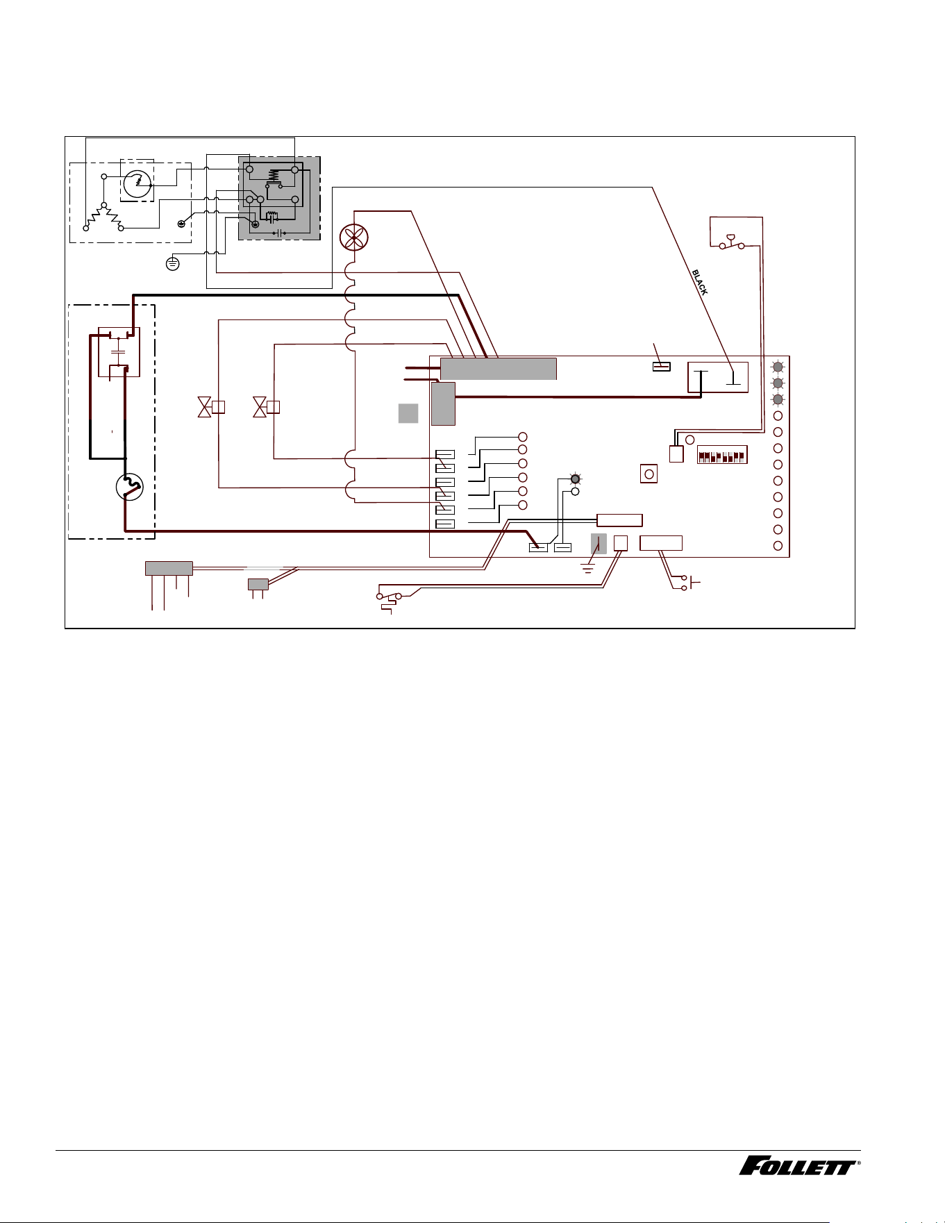
Normal operation – Stage 2
When continuity is seen between B and C, the water valve de-energizes, the AUGER output (P4) comes on along
with the MAKING ICE LED. The auger gearmotor’s start windings are energized through a current style start relay
that is pulled in by the initial high current draw of the gearmotor.
MAINTENANCE
LOW WATER
TIME DELAY
SLEEP CYCLE
MAKING ICE
LOW BIN
POWER
SERVICE
HI AMPS
HI PRESSURE
DRAIN CLOG
CLEANER FULL
High
Pressure
Switch
Gearmotor
L2/N
L1
Fan
A B C D
Water Sensors
RESET
Fill
Valve
Drain
Valve
Bin T-Stat
Clean Switch
Drain Clog Sensor
P6
P21
P20
P19
P3
P22
P4
AUGER
WATER LEVELS
BIN
P11
HI PRS
WHITE
BLACK
BROWN
BLUE
RED
COMPRESSOR
1 2 3 4 5 6 7 8
BLACK
N
P15
Ice Dispense Input
L1
WHITE
WHITE
WHITE
WHITE
BLACK
Cs
Cr
1
5
2
4
4
P5
T.O.L.
Capacitor
BLACK
YELLOW
NO CONNECT
VIOLET
BLACK
RED
BLACK
ORANGE
YELLOW
c
s
R
Compressor
Electrical Box
Optional in Certain
Compressor Models
Compressor
16 D414A/W, R414A/W, D414A/W_F, P414A/W Ice Machines
Normal operation – Stage 3
After the initial high current draw drops off, the gearmotor start relay contacts open, dropping out the start winding.
The condenser fan output (P3) comes on 0.5 seconds later.
MAINTENANCE
LOW WATER
TIME DELAY
SLEEP CYCLE
MAKING ICE
LOW BIN
POWER
SERVICE
HI AMPS
HI PRESSURE
DRAIN CLOG
CLEANER FULL
High
Pressure
Switch
Gearmotor
L2/N
L1
Fan
A B C D
Water Sensors
RESET
Fill
Valve
Drain
Valve
Bin T-Stat
Clean Switch
Drain Clog Sensor
P6
P21
P20
P19
P3
P22
P4
AUGER
WATER LEVELS
BIN
P11
HI PRS
WHITE
BLACK
BROWN
BLUE
RED
COMPRESSOR
1 2 3 4 5 6 7 8
BLACK
N
P15
Ice Dispense Input
L1
WHITE
WHITE
WHITE
WHITE
BLACK
Cs
Cr
1
5
2
4
4
P5
T.O.L.
Capacitor
BLACK
YELLOW
NO CONNECT
VIOLET
BLACK
RED
BLACK
ORANGE
YELLOW
c
s
R
Compressor
Electrical Box
Optional in Certain
Compressor Models
Compressor
D414A/W, R414A/W, D414A/W_F, P414A/W Ice Machines 17
Normal operation – Stage 4
One second (1 s) after the fan comes on, the COMPRESSOR output comes on. The compressor circuit uses both
run and start capacitors along with a potential start relay. The start capacitor in energized through the normally
closed contacts of the start relay.
MAINTENANCE
LOW WATER
TIME DELAY
SLEEP CYCLE
MAKING ICE
LOW BIN
POWER
SERVICE
HI AMPS
HI PRESSURE
DRAIN CLOG
CLEANER FULL
High
Pressure
Switch
Gearmotor
L2/N
L1
Fan
A B C D
Water Sensors
RESET
Fill
Valve
Drain
Valve
Bin T-Stat
Clean Switch
Drain Clog Sensor
P6
P21
P20
P19
P3
P22
P4
AUGER
WATER LEVELS
BIN
P11
HI PRS
WHITE
BLACK
BROWN
BLUE
RED
COMPRESSOR
1 2 3 4 5 6 7 8
BLACK
N
P15
Ice Dispense Input
L1
WHITE
WHITE
WHITE
WHITE
BLACK
Cs
Cr
1
5
2
4
4
P5
T.O.L.
Capacitor
BLACK
YELLOW
NO CONNECT
VIOLET
BLACK
RED
BLACK
ORANGE
YELLOW
c
s
R
Compressor
Electrical Box
Optional in Certain
Compressor Models
Compressor
18 D414A/W, R414A/W, D414A/W_F, P414A/W Ice Machines
Normal operation – Stage 5
As the compressor comes up to normal running speed, its start winding generates a voltage potential across the
relay’s coil. This energizes the coil to open the contact and drop out the start capacitor.
The ice machine is now in a normal ice making mode. The ice machine will produce ice until the bin level control
in the ice dispenser is satised.
MAINTENANCE
LOW WATER
TIME DELAY
SLEEP CYCLE
MAKING ICE
LOW BIN
POWER
SERVICE
HI AMPS
HI PRESSURE
DRAIN CLOG
CLEANER FULL
High
Pressure
Switch
Gearmotor
L2/N
L1
Fan
A B C D
Water Sensors
RESET
Fill
Valve
Drain
Valve
Bin T-Stat
Clean Switch
Drain Clog Sensor
P6
P21
P20
P19
P3
P22
P4
AUGER
WATER LEVELS
BIN
P11
HI PRS
WHITE
BLACK
BROWN
BLUE
RED
COMPRESSOR
1 2 3 4 5 6 7 8
BLACK
N
P15
Ice Dispense Input
L1
WHITE
WHITE
WHITE
WHITE
BLACK
Cs
Cr
1
5
2
4
4
P5
T.O.L.
Capacitor
BLACK
YELLOW
NO CONNECT
VIOLET
BLACK
RED
BLACK
ORANGE
YELLOW
c
s
R
Compressor
Electrical Box
Optional in Certain
Compressor Models
Compressor
D414A/W, R414A/W, D414A/W_F, P414A/W Ice Machines 19
Normal operation – Stage 6
Once the bin thermostat control opens, the LOW BIN LED goes out. The compressor and gear motor outputs turn
off, the MAKING ICE LED goes out and the TIME DELAY LED comes on. .
MAINTENANCE
LOW WATER
TIME DELAY
SLEEP CYCLE
MAKING ICE
LOW BIN
POWER
SERVICE
HI AMPS
HI PRESSURE
DRAIN CLOG
CLEANER FULL
High
Pressure
Switch
Gearmotor
L2/N
L1
Fan
A B C D
Water Sensors
RESET
Fill
Valve
Drain
Valve
Bin T-Stat
Clean Switch
Drain Clog Sensor
P6
P21
P20
P19
P3
P22
P4
AUGER
WATER LEVELS
BIN
P11
HI PRS
WHITE
BLACK
BROWN
BLUE
RED
COMPRESSOR
1 2 3 4 5 6 7 8
BLACK
N
P15
Ice Dispense Input
L1
WHITE
WHITE
WHITE
WHITE
BLACK
Cs
Cr
1
5
2
4
4
P5
T.O.L.
Capacitor
BLACK
YELLOW
NO CONNECT
VIOLET
BLACK
RED
BLACK
ORANGE
YELLOW
c
s
R
Compressor
Electrical Box
Optional in Certain
Compressor Models
Compressor
20 D414A/W, R414A/W, D414A/W_F, P414A/W Ice Machines
Normal operation – Stage 7
The fan motor continues for 10 minutes before shutting off. The TIME DELAY LED remains on for 20 minutes.
The ice machine will not start while the TIME DELAY LED is on. To restart the ice machine for troubleshooting
purposes, depress the reset button to clear the control board.
MAINTENANCE
LOW WATER
TIME DELAY
SLEEP CYCLE
MAKING ICE
LOW BIN
POWER
SERVICE
HI AMPS
HI PRESSURE
DRAIN CLOG
CLEANER FULL
High
Pressure
Switch
Gearmotor
L2/N
L1
Fan
A B C D
Water Sensors
RESET
Fill
Valve
Drain
Valve
Bin T-Stat
Clean Switch
Drain Clog Sensor
P6
P21
P20
P19
P3
P22
P4
AUGER
WATER LEVELS
BIN
P11
HI PRS
WHITE
BLACK
BROWN
BLUE
RED
COMPRESSOR
1 2 3 4 5 6 7 8
BLACK
N
P15
Ice Dispense Input
L1
WHITE
WHITE
WHITE
WHITE
BLACK
Cs
Cr
1
5
2
4
4
P5
T.O.L.
Capacitor
BLACK
YELLOW
NO CONNECT
VIOLET
BLACK
RED
BLACK
ORANGE
YELLOW
c
s
R
Compressor
Electrical Box
Optional in Certain
Compressor Models
Compressor
D414A/W, R414A/W, D414A/W_F, P414A/W Ice Machines 21
Normal operation – Stage 8
When the dwell time of 20 minutes has expired, the TIME DELAY LED goes off. If 5 seconds of ice has been
dispensed and the SLEEP CYCLE LED (Symphony Plus only) is off, the ice machine will go through the normal
start-up sequence when the bin level control signals the control board for ice.
MAINTENANCE
LOW WATER
TIME DELAY
SLEEP CYCLE
MAKING ICE
LOW BIN
POWER
SERVICE
HI AMPS
HI PRESSURE
DRAIN CLOG
CLEANER FULL
High
Pressure
Switch
Gearmotor
L2/N
L1
Fan
A B C D
Water Sensors
RESET
Fill
Valve
Drain
Valve
Bin T-Stat
Clean Switch
Drain Clog Sensor
P6
P21
P20
P19
P3
P22
P4
AUGER
WATER LEVELS
BIN
P11
HI PRS
WHITE
BLACK
BROWN
BLUE
RED
COMPRESSOR
1 2 3 4 5 6 7 8
BLACK
N
P15
Ice Dispense Input
L1
WHITE
WHITE
WHITE
WHITE
BLACK
Cs
Cr
1
5
2
4
4
P5
T.O.L.
Capacitor
BLACK
YELLOW
NO CONNECT
VIOLET
BLACK
RED
BLACK
ORANGE
YELLOW
c
s
R
Compressor
Electrical Box
Optional in Certain
Compressor Models
Compressor
Quiet Night/Sleep cycle (Symphony Plus only)
The board monitors ice dispensing through a line voltage input to P15. If the ice dispense has not be initiated for
more than 5 seconds during the 20 minute time delay, the SLEEP CYCLE LED comes on. The machine will stay
off for 12 hours unless 5 seconds of dispensing is seen. After 12 hours, the SLEEP CYCLE LED goes out and the
ice making will resume if the bin thermostat is closed. The sleep cycle dispense duration is adjustable using the
DIP switches on the control board.
22 D414A/W, R414A/W, D414A/W_F, P414A/W Ice Machines
Self-ushing (when enabled)
At the completion of the 20 minute time delay, the machine checks for a cumulative one hour of ice making time
since the last off-cycle ush. If the cumulative ice making time exceeds one hour, the machine will energize the
drain valve P19 for 60 seconds to drain the evaporator. It will then rell with water, ush again, rell and begin
making ice if the LOW BIN LED is on. If the ice making time is less than 1 hour, the machine will start and begin
making ice without draining the evaporator.
MAINTENANCE
LOW WATER
TIME DELAY
SLEEP CYCLE
MAKING ICE
LOW BIN
POWER
SERVICE
HI AMPS
HI PRESSURE
DRAIN CLOG
CLEANER FULL
High
Pressure
Switch
Gearmotor
L2/N
L1
Fan
A B C D
Water Sensors
RESET
Fill
Valve
Drain
Valve
Bin T-Stat
Clean Switch
Drain Clog Sensor
P6
P21
P20
P19
P3
P22
P4
AUGER
WATER LEVELS
BIN
P11
HI PRS
WHITE
BLACK
BROWN
BLUE
RED
COMPRESSOR
1 2 3 4 5 6 7 8
BLACK
N
P15
Ice Dispense Input
L1
WHITE
WHITE
WHITE
WHITE
BLACK
Cs
Cr
1
5
2
4
4
P5
T.O.L.
Capacitor
BLACK
YELLOW
NO CONNECT
VIOLET
BLACK
RED
BLACK
ORANGE
YELLOW
c
s
R
Compressor
Electrical Box
Optional in Certain
Compressor Models
Compressor
D414A/W, R414A/W, D414A/W_F, P414A/W Ice Machines 23
Diagnostic Stages
High gearmotor amps – Stage 1
The HI AMPS error and TIME DELAY LEDs are on indicating that the control board has sensed an over-torque
condition at the P4 terminal (more than 3 amps from the gearmotor) or no current draw (0A) and shut the ice
machine down (strike one). The HI AMPS and TIME DELAY LEDs will remain on for 60 minutes after an over-
torque condition has occurred. The ice machine will remain off as long as these two LEDs are on. After the
60 minute time delay, these LED lights turn off, and the control board will try to go through a normal start-up
sequence.
MAINTENANCE
LOW WATER
TIME DELAY
SLEEP CYCLE
MAKING ICE
LOW BIN
POWER
SERVICE
HI AMPS
HI PRESSURE
DRAIN CLOG
CLEANER FULL
High
Pressure
Switch
Gearmotor
L2/N
L1
Fan
A B C D
Water Sensors
RESET
Fill
Valve
Drain
Valve
Bin T-Stat
Clean Switch
Drain Clog Sensor
P6
P21
P20
P19
P3
P22
P4
AUGER
WATER LEVELS
BIN
P11
HI PRS
WHITE
BLACK
BROWN
BLUE
RED
COMPRESSOR
1 2 3 4 5 6 7 8
BLACK
N
P15
Ice Dispense Input
Capacitor
BLACK
YELLOW
NO CONNECT
L1
WHITE
WHITE
WHITE
WHITE
BLACK
Cs
Cr
1
5
2
4
4
P5
T.O.L.
VIOLET
BLACK
RED
BLACK
ORANGE
YELLOW
c
s
R
Compressor
Electrical Box
Optional in Certain
Compressor Models
Compressor
24 D414A/W, R414A/W, D414A/W_F, P414A/W Ice Machines
High gearmotor amps – Stage 2
If the restart is successful the board will continue to monitor the current draw on P4 for 60 minutes looking for
a second high amps (above 3A) occurrence. If the ice machine runs without problems for 60 minutes and no
additional torque errors occur, the ice machine will continue normal operation.
MAINTENANCE
LOW WATER
TIME DELAY
SLEEP CYCLE
MAKING ICE
LOW BIN
POWER
SERVICE
HI AMPS
HI PRESSURE
DRAIN CLOG
CLEANER FULL
High
Pressure
Switch
Gearmotor
L2/N
L1
Fan
A B C D
Water Sensors
RESET
Fill
Valve
Drain
Valve
Bin T-Stat
Clean Switch
Drain Clog Sensor
P6
P21
P20
P19
P3
P22
P4
AUGER
WATER LEVELS
BIN
P11
HI PRS
WHITE
BLACK
BROWN
BLUE
RED
COMPRESSOR
1 2 3 4 5 6 7 8
BLACK
N
P15
Ice Dispense Input
L1
WHITE
WHITE
WHITE
WHITE
BLACK
Cs
Cr
1
5
2
4
4
P5
T.O.L.
Capacitor
BLACK
YELLOW
NO CONNECT
VIOLET
BLACK
RED
BLACK
ORANGE
YELLOW
c
s
R
Compressor
Electrical Box
Optional in Certain
Compressor Models
Compressor
D414A/W, R414A/W, D414A/W_F, P414A/W Ice Machines 25
High gearmotor amps – Stage 3
If a second occurrence happens during the 60 minute monitoring period, the HI AMPS LED will come on again
and shut the machine down (strike two). The HI AMPS LED (wihout the TIME DELAY LED) will indicate to the
technician that two consecutive over-torque situations have occurred. The ice machine is shut down at this time
and locked out. It will not restart unless the manual reset button is depressed while power is on.
MAINTENANCE
LOW WATER
TIME DELAY
SLEEP CYCLE
MAKING ICE
LOW BIN
POWER
SERVICE
HI AMPS
HI PRESSURE
DRAIN CLOG
CLEANER FULL
High
Pressure
Switch
Gearmotor
L2/N
L1
Fan
A B C D
Water Sensors
RESET
Fill
Valve
Drain
Valve
Bin T-Stat
Clean Switch
Drain Clog Sensor
P6
P21
P20
P19
P3
P22
P4
AUGER
WATER LEVELS
BIN
P11
HI PRS
WHITE
BLACK
BROWN
BLUE
RED
COMPRESSOR
1 2 3 4 5 6 7 8
BLACK
N
P15
Ice Dispense Input
Capacitor
BLACK
YELLOW
NO CONNECT
L1
WHITE
WHITE
WHITE
WHITE
BLACK
Cs
Cr
1
5
2
4
4
P5
T.O.L.
VIOLET
BLACK
RED
BLACK
ORANGE
YELLOW
c
s
R
Compressor
Electrical Box
Optional in Certain
Compressor Models
Compressor
26 D414A/W, R414A/W, D414A/W_F, P414A/W Ice Machines
D414A/W, R414A/W, D414A/W_F, P414A/W Ice Machines 27
Loss of water
During operation, the water level cycles between the normal low (D) and normal high (C) water probes - the ll
valve (P21) cycling on and off. If continuity is not detected between the common probe (B) and normal low (D)
within 10 seconds, the LOW WATER and TIME DELAY LEDs will come on and the machine will shut down for
the one hour time delay period. After the time delay, the ll valve will re-energize and wait for continuity between
the common probe and normal high before restarting. LOW WATER LED will remain ON until the water level is
satised.
MAINTENANCE
LOW WATER
TIME DELAY
SLEEP CYCLE
MAKING ICE
LOW BIN
POWER
SERVICE
HI AMPS
HI PRESSURE
DRAIN CLOG
CLEANER FULL
High
Pressure
Switch
Gearmotor
L2/N
L1
Fan
A B C D
Water Sensors
RESET
Fill
Valve
Drain
Valve
Bin T-Stat
Clean Switch
Drain Clog Sensor
P6
P21
P20
P19
P3
P22
P4
AUGER
WATER LEVELS
BIN
P11
HI PRS
WHITE
BLACK
BROWN
BLUE
RED
COMPRESSOR
1 2 3 4 5 6 7 8
BLACK
N
P15
Ice Dispense Input
Capacitor
BLACK
YELLOW
NO CONNECT
L1
WHITE
WHITE
WHITE
WHITE
BLACK
Cs
Cr
1
5
2
4
4
P5
T.O.L.
VIOLET
BLACK
RED
BLACK
ORANGE
YELLOW
c
s
R
Compressor
Electrical Box
Optional in Certain
Compressor Models
Compressor
28 D414A/W, R414A/W, D414A/W_F, P414A/W Ice Machines
High refrigerant pressure
Should the refrigeration pressure rise above 425 psi, the high pressure switch contacts will open. The board sees
the open circuit and the HIGH PRESSURE and TIME DELAY LEDs will come on, the machine shuts down. After
the one hour time delay, the machine will attempt to restart. If the pressure has fallen below the reset point of 295
psi and the board see the contacts closed, the machine will resume normal operation. If the contacts are still open
after the restart, the board will again go into HIGH PRESSURE and TIME DELAY, cycling until contact closure is
seen.
MAINTENANCE
LOW WATER
TIME DELAY
SLEEP CYCLE
MAKING ICE
LOW BIN
POWER
SERVICE
HI AMPS
HI PRESSURE
DRAIN CLOG
CLEANER FULL
High
Pressure
Switch
Gearmotor
L2/N
L1
Fan
A B C D
Water Sensors
RESET
Fill
Valve
Drain
Valve
Bin T-Stat
Clean Switch
Drain Clog Sensor
P6
P21
P20
P19
P3
P22
P4
AUGER
WATER LEVELS
BIN
P11
HI PRS
WHITE
BLACK
BROWN
BLUE
RED
COMPRESSOR
1 2 3 4 5 6 7 8
BLACK
N
P15
Ice Dispense Input
Capacitor
BLACK
YELLOW
NO CONNECT
L1
WHITE
WHITE
WHITE
WHITE
BLACK
Cs
Cr
1
5
2
4
4
P5
T.O.L.
VIOLET
BLACK
RED
BLACK
ORANGE
YELLOW
c
s
R
Compressor
Electrical Box
Optional in Certain
Compressor Models
Compressor
Service
If continuity is seen between the two drain clog sensor probes, the SERVICE LED will come on and the machine
will shut down. The machine will not restart unless the manual reset button is depressed while power is on.
MAINTENANCE
LOW WATER
TIME DELAY
SLEEP CYCLE
MAKING ICE
LOW BIN
POWER
SERVICE
HI AMPS
HI PRESSURE
DRAIN CLOG
CLEANER FULL
High
Pressure
Switch
Gearmotor
L2/N
L1
Fan
A B C D
Water Sensors
RESET
Fill
Valve
Drain
Valve
Bin T-Stat
Clean Switch
Drain Clog Sensor
P6
P21
P20
P19
P3
P22
P4
AUGER
WATER LEVELS
BIN
P11
HI PRS
WHITE
BLACK
BROWN
BLUE
RED
COMPRESSOR
1 2 3 4 5 6 7 8
BLACK
N
P15
Ice Dispense Input
Capacitor
BLACK
YELLOW
NO CONNECT
L1
WHITE
WHITE
WHITE
WHITE
BLACK
Cs
Cr
1
5
2
4
4
P5
T.O.L.
VIOLET
BLACK
RED
BLACK
ORANGE
YELLOW
c
s
R
Compressor
Electrical Box
Optional in Certain
Compressor Models
Compressor
D414A/W, R414A/W, D414A/W_F, P414A/W Ice Machines 29
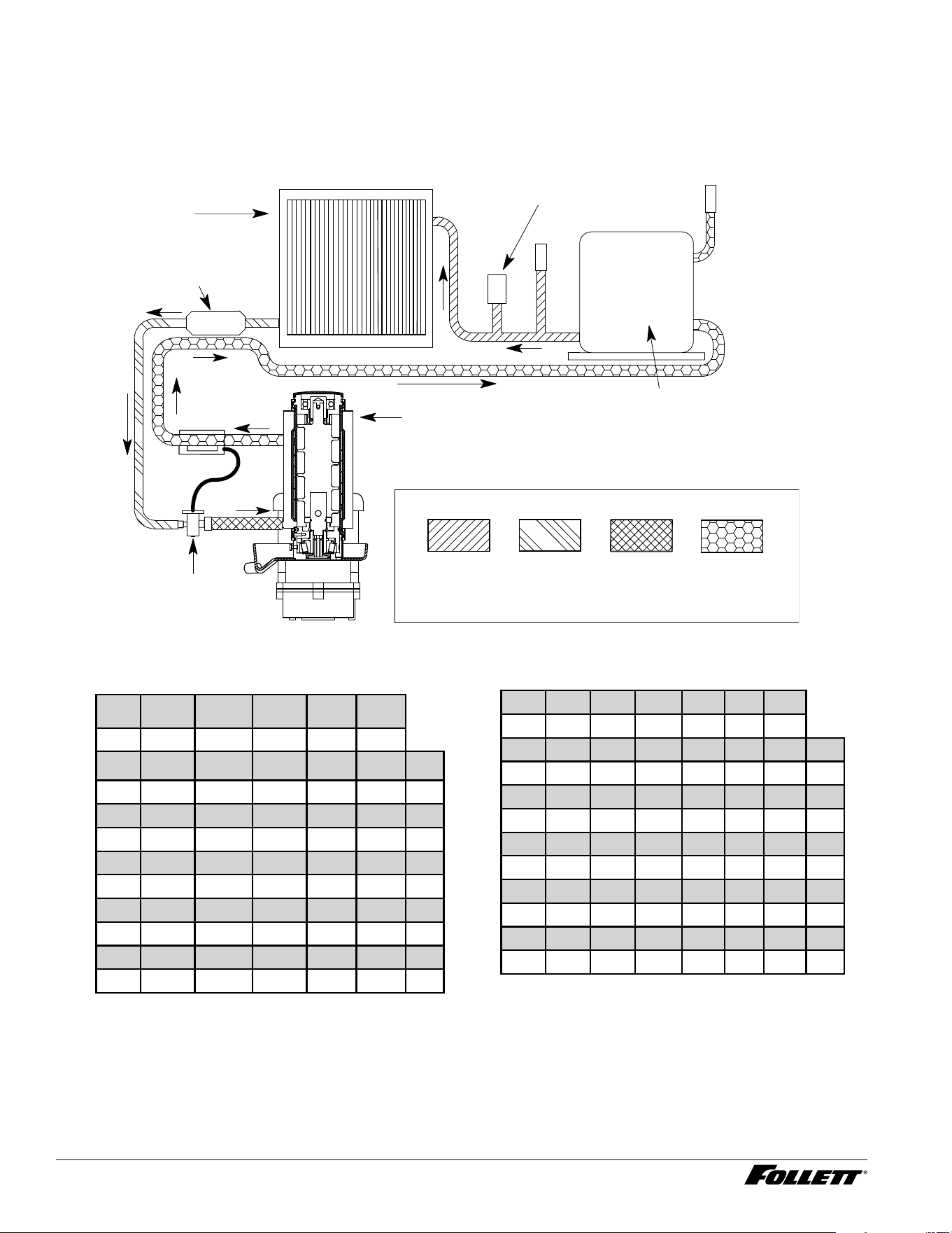
Refrigeration system (all models)
All service on refrigeration systems must be performed in accordance with all federal, state and local laws. It is the
responsibility of the technician to ensure that these requirements are met. Recharging ice machine to other than
factory specications will void the warranty.
Refrigeration system diagram
condenser
lter dryer
thermostatic
expansion
valve
evaporator
high pressure
switch
compressor
high
pressure
vapor
low
pressure
vapor
high
pressure
liquid
low
pressure
liquid
Air-Cooled ice machine capacity/24hrs.
Ambient Air Temperature F/C
Inlet Water Temperature F/C
F 60 70 80 90 100
C 16 21 27 32 38
50 460 425 390 355 320 lbs.
10 208 193 177 161 145 kg.
60 437.5 405 372.5 340 307.5 lbs.
16 198 184 169 154 139 kg.
70 415 385 355 325 295 lbs.
21 188 175 161 147 134 kg.
80 405 375 345 315 285 lbs.
27 184 170 156 142 129 kg.
90 395 365 335 305 275 lbs.
32 179 166 152 138 125 kg.
Water-Cooled ice machine capacity/24hrs.
Condenser Water Temperature F/C
Inlet Water Temperature F/C
F 50 60 70 80 90 100
C 10 16 21 27 32 38
50 486 465 443 422 400 389 lbs.
10 220 211 201 191 181 176 kg.
60 464 445 425 406 386 367 lbs.
16 210 202 193 184 175 166 kg.
70 443 425 408 390 372 358 lbs.
21 201 193 185 177 169 162 kg.
80 422 406 389 373 356 340 lbs.
27 191 184 176 169 161 154 kg.
90 400 385 371 356 341 326 lbs.
32 181 175 168 161 155 148 kg.
Note: Nominal values - actual production may vary by ±10%.
30 D414A/W, R414A/W, D414A/W_F, P414A/W Ice Machines
D414A/W, R414A/W, D414A/W_F, P414A/W Ice Machines 31
R290 ice machine charge specications
Model Charge Refrigerant type
D414A (air-cooled) 3.49 oz. (99 g) R290
D414W (water-cooled) 1.83 oz. (52 g) R290
Refrigerant replacement requirements
1. Non-contaminated refrigerant removed from any Follett refrigeration system can be recycled and
returned to the same system after completing repairs. Recycled refrigerant must be stored in a clean,
approved storage container. If additional refrigerant is required, virgin or reclaimed refrigerant that meets
ARI standard 700-88 must be used.
2. In the event of system contamination (for example, a compressor burn out, refrigerant leak, presence of
non-condensibles or moisture), the system must be repaired, evacuated and recharged using virgin or
reclaimed refrigerant that meets ARI standard 700-88.
3. Follett Corporation does not approve of recovered refrigerants. Improper refrigeration servicing
procedures will void the factory warranty.
Evacuation
Evacuate the system to a level of 500 microns. When the 500 micron level is reached, close valves and both
manifold and shut down the vacuum pump. Allow the system to sit for approximately 20 minutes. During this period
the system pressure should not rise. If the system pressure rises and stabilizes there is moisture in the system and
further evacuation is needed. If the pressure continues to rise check the system for leaks.
Ice capacity test
Ice machine production capacity can only be determined by weighing ice produced in a specic time period.
Replace all panels on ice machine.
1. Run ice machine for at least 15 minutes.
2. Weigh and record weight of container used to catch ice.
3. Catch ice for 15 or 20 minutes.
4. Weigh harvested ice and record total weight.
5. Subtract weight of container from total weight.
6. Convert fractions of pounds to decimal equivalents (ex. 6 lb 8 oz. = 6.5 lb).
7. Calculate production using following formula:
1440 min. x wt. of ice produced
= Production capacity/24 hr. period
Total test time in minutes
8. Calculated amount per 24 hours should be checked against rated capacity for same ambient and water
temperatures in Ice Production Tables.
32 D414A/W, R414A/W, D414A/W_F, P414A/W Ice Machines
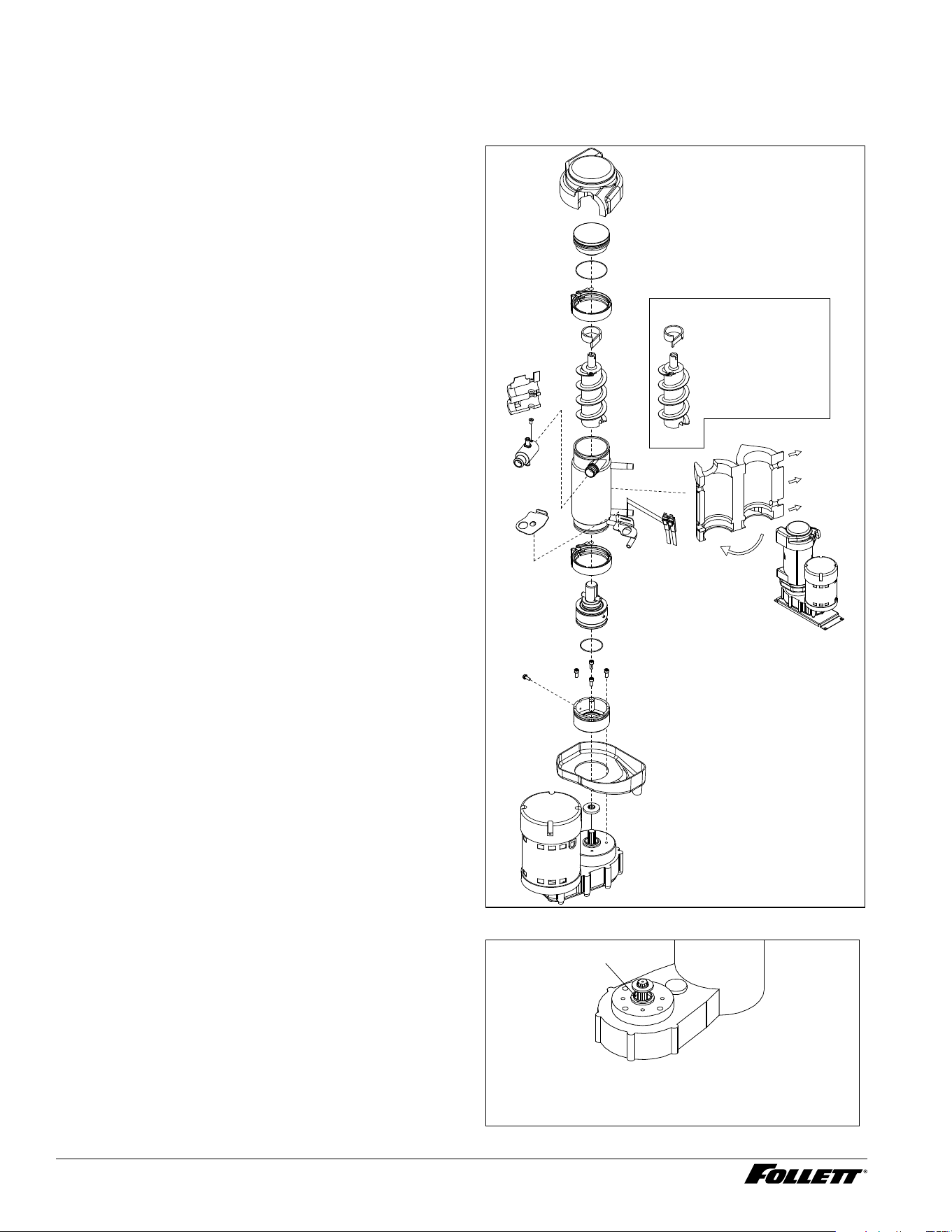
Evaporator disassembly
Note: The upper bearing, lower bearing and auger assemblies must be replaced as assemblies. The bottom and
top bearing assemblies cannot be eld assembled to factory specications.
1. Press CLEAN switch.
2. Wait for LOW WATER light to illuminate.
3. Turn OFF power.
4. Remove top bearing insulation and
compression nozzle insulation.
5. Disconnect vent and drain tube from nozzle.
6. Disconnect compression nozzle from
evaporator.
7. Disconnect evaporator water feed line.
8. Remove nut and upper v-band coupling from
top of evaporator.
9. Lift top bearing assembly straight up with a
slight rotating motion and remove.
10. Remove ice compression loop located at top
of auger.
11. Lift auger straight up and out of evaporator.
12. Remove nut and lower vee band coupling
from bottom of evaporator.
13. Lift evaporator to clear bottom bearing
assembly.
14. Loosen hex head bolt in side of mounting
base with 5/16 wrench and lift lower bearing
assembly.
15. Remove condensate shield.
16. Remove 4 Allen head machine screws holding
mounting base to gearbox.
Fig. 3
AUGER 00124123
COMPRESSION
FLAKER COMPONENTS
LOOP 00124115
Evaporator reassembly
1. Clean gearmotor boss, output shaft and shaft
well.
2. Install drain pan and evaporator mounting
base.
3. Fill gear motor shaft well with food grade
grease (Fig. 4).
4. Install condensate shield and seat against
gear motor boss.
5. Install bearing O ring in groove in evaporator
mounting base.
Fig. 4
Apply grease in well
Evaporator drain pan and mounting base not shown for clarity.
D414A/W, R414A/W, D414A/W_F, P414A/W Ice Machines 33
6. Lower bottom bearing assembly into
evaporator mounting base.
7. While maintaining rm downward pressure
on bottom bearing assembly, tighten hex
head bolt with a 5/16 wrench.
8. Position evaporator over lower bearing
assembly and align grooves with pins in
bearing assembly.
9. Install vee band clamp and nut to 70 in/lb.
(Fig. 5).
Note: Clamp must be oriented as shown
in order for the insulation to be placed
properly.
10. Place auger in center of evaporator and
rotate to mate with drive pin.
11. Install ice compression loop, orienting loop.
12. Install upper bearing and seal assembly,
rotating bearing to slip pin into auger slot.
13. Install upper vee band clamp and nut to
70in/lb.
14. Install evaporator insulation.
15. Install compression nozzle and tubing.
16. Secure ice transport tube with clamp
(Fig.6.1).
Note: Clamp must be oriented as shown
in order for the insulation to be placed
properly.
1 7. Install compression nozzle insulation
(Fig.6.2).
18. Install vent and drain tube (Fig.6.3).
19. Install top bearing insulation (Fig.6.4).
Gearmotor replacement
1. Disassemble evaporator.
2. Disconnect the wire connectors.
3. Remove 4 screws holding gear motor
mounting plate to base of ice machine and
lift gearbox and motor clear of ice machine.
4. Remove machine screws holding mounting
plate to motor.
5. Install new motor in reverse order.
Fig. 5
Fig. 6
4
3
3
1
2

34 D414A/W, R414A/W, D414A/W_F, P414A/W Ice Machines
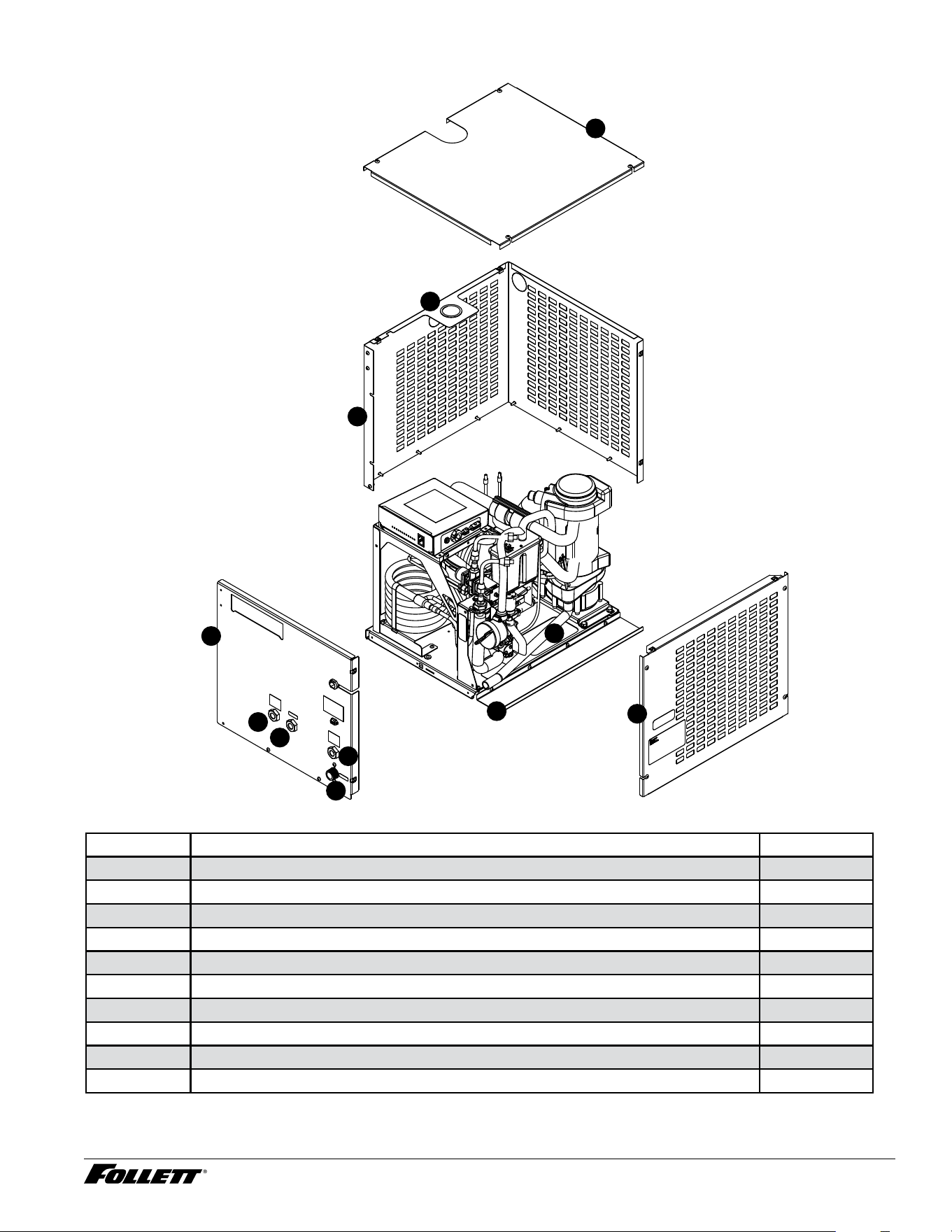
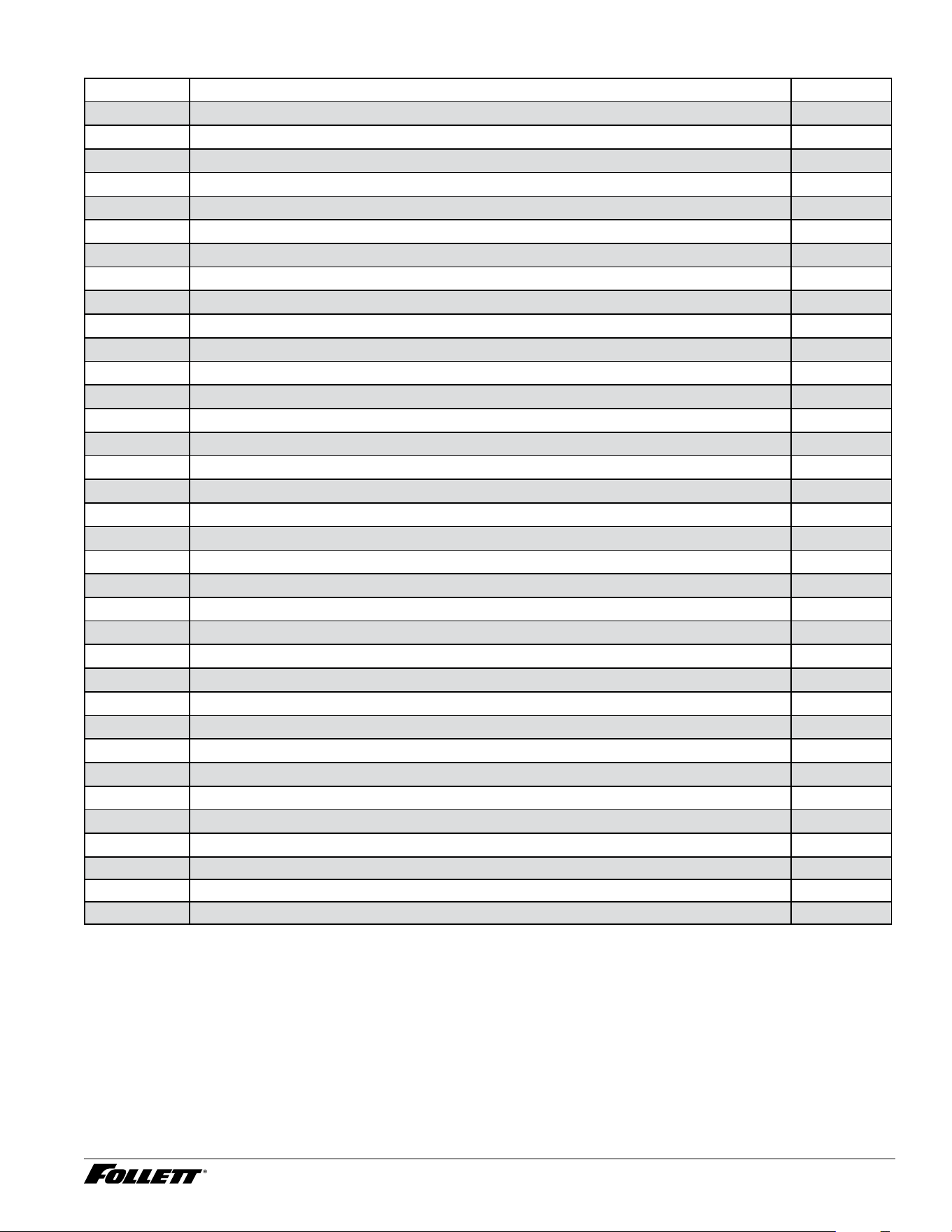
Replacement parts
Air-cooled skins assembly (D414A)
7
10
9
8
6
5
1
11
3
2
4
Reference # Description Part #
1 Gasket, duct 502781
2 Duct (including gasket) 01068188
3 Front panel 01068204
4 Spacer, base 01068220
5 Panel, right side 01068238
6 Panel, left side and rear (1 piece) 01068246
7 Bushing 01026152
8 Panel, top 01575257
9 Tube, drain 01016948
10 Fitting, water 01065275
11 Fitting, drain 00109728
D414A/W, R414A/W, D414A/W_F, P414A/W Ice Machines 35
Water-cooled skins assembly (D414W)
7
10
9
8
6
5
1
1
3
2
4
Reference # Description Part #
1 Fitting, condenser 00195966
2 Fitting, water 01065275
3 Fitting, drain 00109728
4 Panel, front 01068261
5 Spacer, base 01068220
6 Panel, right side 01068238
7 Tube, drain 01016948
8 Panel, left side and rear (1 piece) 01068246
9 Bushing 01026152
10 Panel, top 01575257
36 D414A/W, R414A/W, D414A/W_F, P414A/W Ice Machines
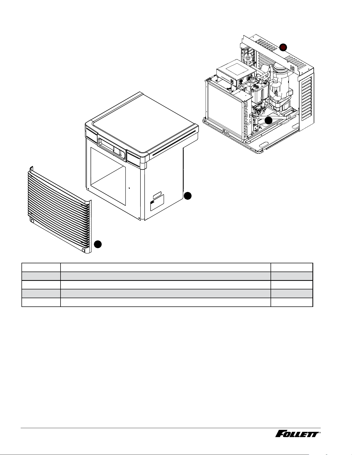
Louvered docking station (D414A/W_T)
1
2
3
4
Reference # Description Part #
1 Louver, front 01006154
2 Cover, front 01575265
3 Tube, drain 01055185
4 Lovered docking station 01068287
D414A/W, R414A/W, D414A/W_F, P414A/W Ice Machines 37
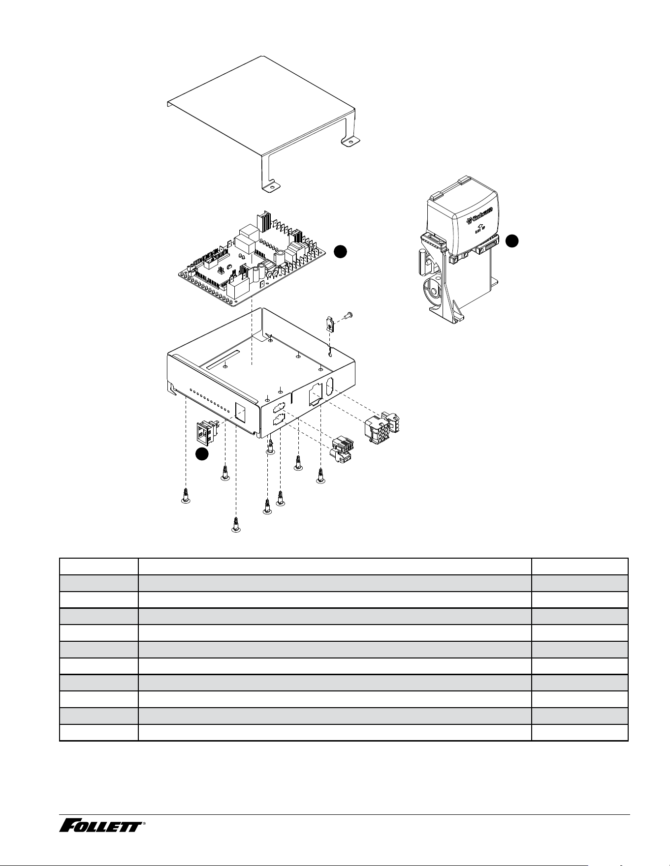
Electrical components
1
3
2
Reference # Description Part #
1 Compressor start component 01572122
2 Board, control circuit, 115 V, 60 Hz 01064708
3 Switch, clean 01229418
Not shown Bin thermostat 500514
Not shown Board, stand off control (8 required) 00903005
Not shown Relay, power to contact closure 01020734
Not shown Jumper, bin signal 01069095
Not shown Cord and plug, power 01075589
Not shown Converter, bin signal, Vision 01067156
Not shown Relay, bin signal (power to contact closure) 01020734
38 D414A/W, R414A/W, D414A/W_F, P414A/W Ice Machines
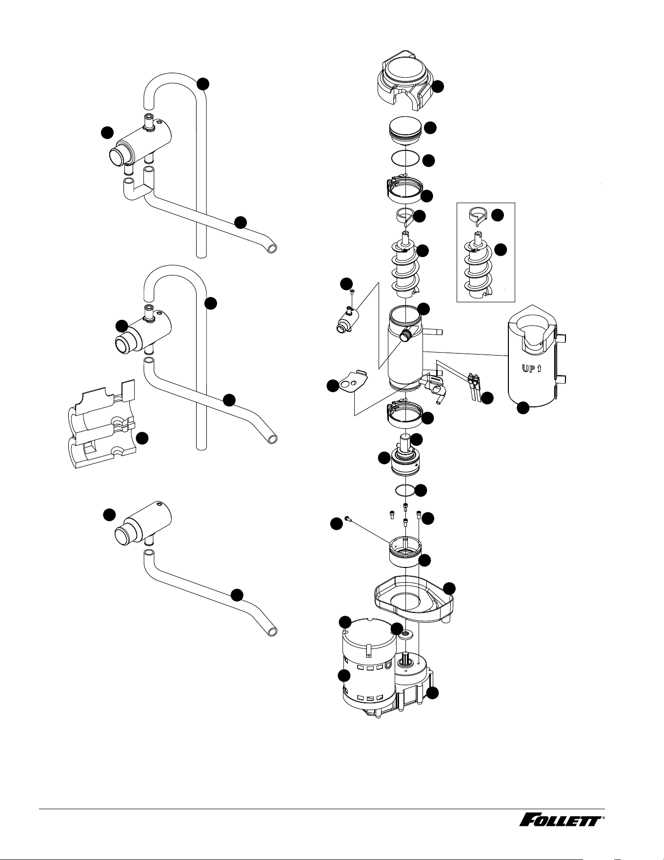
Evaporator
FOOD SERVICE
HEALTHCARE
FLAKER
FLAKER
COMPONENTS
27
15
17
25
1
3
4
5
20
19
7
6
8
10
11
12
16
9
1
17
18
18
26
24
2
28
23
29
3
4
22
13
21
14
D414A/W, R414A/W, D414A/W_F, P414A/W Ice Machines 39
Evaporator
Reference # Description Part #
1 Coupling, vee band, includes nut 502735
2 Bearing assembly, top 502736
3 Loop, ice compression, beveled (see below for Flaker-specic components) 502110
4 Auger (see below for Flaker-specic components) 502737
5 Evaporator (includes insulation jacket, 01049592) 01064658
6 O ring, bearing housing 500496
7 Bearing assembly, bottom (includes O rings and condensate shield) 502738
8 O ring, mounting base 501063
9 Shield, condensate 500744
10 Screw, Allen 1/4 20 x 1/2 (set of 4) 501080
11 Mounting base, evap. (includes 501063) 502733
12 Bolt, mounting base 502227
13 Gearbox and motor 502730
Not shown Mounting base, gearbox 01067693
14 Cover, aluminum 01106376
15 Compression nozzle, with single drain 01064674
16 Drain pan, evaporator 00181990
17 Tube, compression nozzle vent 01148691
18 Tube, compression nozzle, single drain 01148675
Not shown Grease, Chevron SRI-2, 14 oz 501111
19 Bracket, vent hoses 01007087
20 Insulation jacket, evaporator 01049592
21 Screw, compression nozzle 00956250
22 16 µF Capacitor (for PSC motor only) 01103142
23 Nozzle, compression, dual drain 01067446
24 O ring, top bearing 01064963
25 Tube, compression nozzle, dual drain 01148683
26 Sensor, overow 01039783
27 Insulation, top bearing 01049600
28 Insulation, compression nozzle, single drain 01049584
Not shown O-ring, compression nozzle 00988097
Flaker-specic components
Reference # Description Part #
3 Loop, compression, notched 00124115
4 Auger (with paddle) 00124123
18 Tube, compression nozzle, single drain 01148675
29 Compression nozzle, aker 01067453
40 D414A/W, R414A/W, D414A/W_F, P414A/W Ice Machines
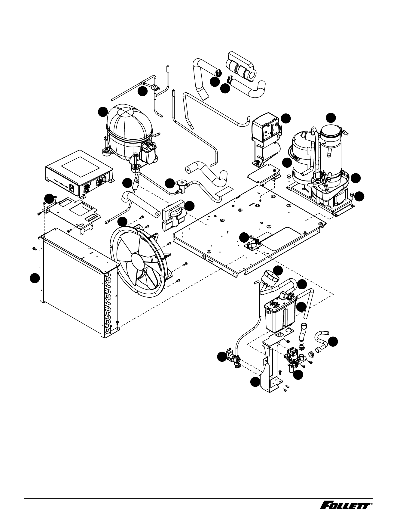
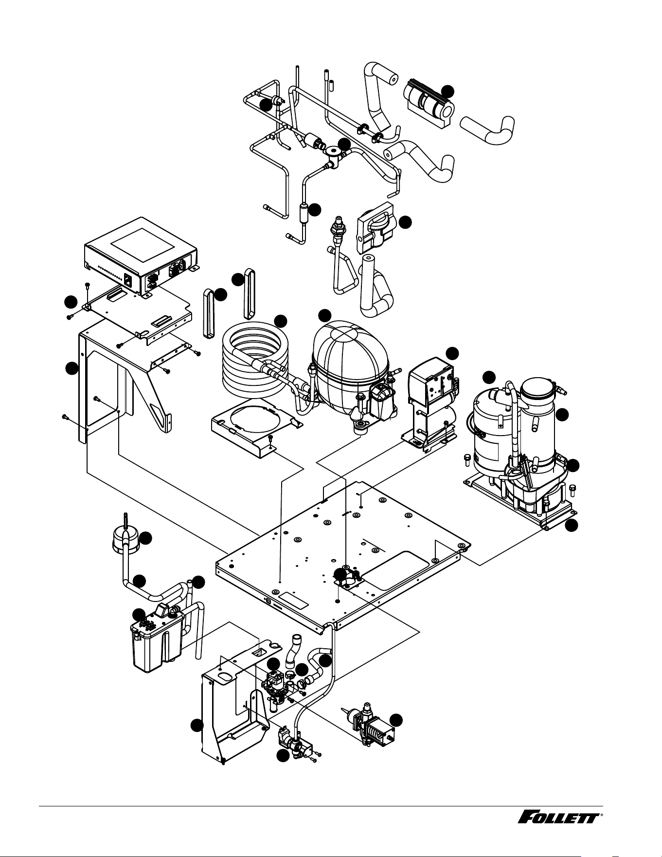
Air-cooled ice machines
2
5
9
16
1
18
21
3
20
17
19
7
6
10
8
11
13
4
12
22
22
14
15
D414A/W, R414A/W, D414A/W_F, P414A/W Ice Machines 41
Air-cooled ice machines
Reference # Description Part #
1 Drier 502724
2 Condenser coil, A/C 01067461
3 Reservoir mounting bracket, a/c 01375609
4 Reservoir assembly (includes lid, gasket, fasteners) 01572163
5 Bracket, electrical box 01068170
6 Evaporator —
Not shown Tubing, polypropylene, reservoir supply (sold by foot) 502079
7 Valve, expansion, thermal 502726
8 Drain pan, evaporator 00181990
9 High pressure cutout 00117077
10 Mounting bracket, gearbox 01067693
11 Gearbox & motor assembly, 115 V, 60 Hz 502730
12 Compressor start components 01572122
13 Condenser fan, motor, and bracket 01222793
14
Cleaning cup tube 01448562
15
Cleaning cup 01448588
Not shown Overload, compressor, 115 V, 60 Hz 01027572
16 Compressor, 115 V, 60 Hz (includes start components) 01571488
17 Tube, ll/purge - reservoir-solenoid-evaporator feed (includes 3 hose clamps) 01261544
Not shown Water inlet tting, brass 01065275
18 Jacket, insulation, TXV 502830
19 Bracket, ice tube entry 01067644
20 Solenoid, purge 01261510
21 Solenoid, ll 01352483
Not shown Tube, drain, D414AT, 25/50FB 01055185
Not shown Tube, drain, D414AT, 110FB, 110CT 01055540
Not shown Tube, drain, D414AS 01016948
Not shown Tube, ice transport, D414A/WT 01003532
Not shown Jacket, insulation, TXV bulb 00106534
22 Clamp, hose (each) 01281450
Not shown Reservoir vent tube 01448570
42 D414A/W, R414A/W, D414A/W_F, P414A/W Ice Machines
Water-cooled ice machines
1
2
3
4
5
6
7
8
10
12
13
14
15
16
16
17
18
19
20
21
22
23
11
9
25
24
26
D414A/W, R414A/W, D414A/W_F, P414A/W Ice Machines 43
Water-cooled ice machines
Reference # Description Part #
1 Drier 502724
2 Valve, water regulating (includes Iso-washer) 500537
Not shown Iso-washer (for water regulating valve) 501810
3 Reservoir assembly (includes lid, gasket, fasteners) 01572163
4 Reservoir mounting bracket 01068162
Not shown Tubing, polypropylene, reservoir supply (sold by foot) 502079
Not shown Fitting, reservoir, plastic 1/4" stem x 1/4" push-in 00121699
5 Evaporator —
6 Bracket, electrical box tower 01068121
7 Valve, expansion, thermal 502726
8 Drain pan, evaporator 00181990
9 Gearbox & motor assembly, 115 V, 60 Hz 502730
10 Mounting bracket, gearbox 01067693
11 Bracket, electrical box mounting 01068139
Not shown Overload compressor, 115 V, 60 Hz 01027572
12 Compressor, 115 V, 60 Hz 01571488
13 Coil, condenser 00195933
14 Compressor start components 01572122
Not shown Water inlet tting, brass 01065275
15 High pressure cutout 00117077
16 Ty-rap (2 required) 204584
17 Tube, ll/purge - reservoir-solenoid-evaporator feed (includes 3 hose clamps) 01261544
18 Bracket, ice tube entry 01067644
19 Solenoid, purge 01261510
20 Solenoid, ll 01352483
Not shown Tube, drain, 25/50CI 01054576
Not shown Tube, drain, D414AT, 25/50FB 01055185
Not shown Tube, drain, D414AT, 110FB, 110CT 01055540
Not shown Tube, drain, D414AS 01016948
21
Clamp, hose (each) 01281450
22 Jacket, insulation, TXV 502830
23 Jacket, insulation, TXV bulb 00106534
24 Cleaning cup tube 01448562
25 Reservoir vent tube 01448570
26 Cleaning cup 01448588
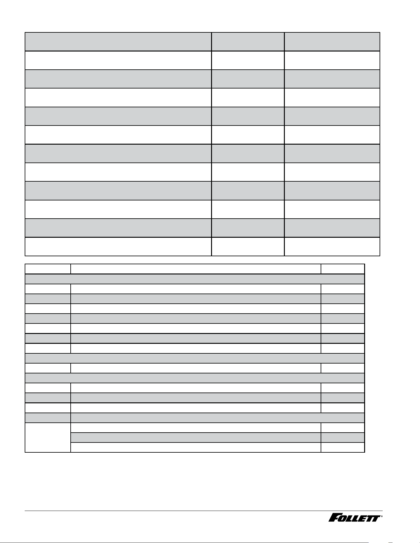
44 D414A/W, R414A/W, D414A/W_F, P414A/W Ice Machines
Water treatment accessories for Symphony ice and water dispensers
Description Old part number
(and capacity)
New Part Number
(and capacity)
Carbonless high-capacity water lter system 01050442
(15,000 gal)
CARBONLESSHICAPSYS
(Based on water conditions)
Carbonless high-capacity water lter cartridge, single 01050426
(15,000 gal)
CARBONLESSHICAPFILT
(Based on water conditions)
Carbonless high-capacity water lter cartridge, carton of 6 01050434
(15,000 gal)
CARBONLESSHICAPFILT6
(Based on water conditions)
Standard capacity carbon lter system 00130229
(3,000 gal)
CARBONSTDCAPSYSTEM
(5,000 gal)
Standard capacity carbon lter cartridge, single 00130245
(3,000 gal)
CARBONSTDCAPFILTER
(5,000 gal)
Standard capacity carbon lter cartridge, carton of 6 00954297
(3,000 gal)
CARBONSTDCAPFILTER6
(5,000 gal)
High-capacity carbon lter system 00978957
(15,000 gal)
CARBONHICAPSYSTEM
(17,500 gal)
High-capacity carbon lter cartridge, single 00978965
(15,000 gal)
CARBONHICAPFILTER
(17,500 gal)
High-capacity carbon lter cartridge, carton of 6 00978973
(15,000 gal)
CARBONHICAPFILTER6
(17,500 gal)
Water pre-lter cartridge, single 00130211
(N/A)
SEDIMENTPREFILTER
(N/A)
Water pre-lter cartridge, carton of 12 00954305
(N/A)
SEDIMENTPREFILTER12
(N/A)
Reference # Description Part #
Other ltration
Not shown Claris hardness removal ltration system 00986059
Not shown Replacement lter for Claris system 00985127
Not shown Reverse osmosis system, 200 gallons per day 00986034
Not shown Replacement reverse osmosis cartridge 00985085
Not shown Replacement reverse osmosis pre-lter 00985077
Not shown Cleaning plug for reverse osmosis system 00985119
Not shown Cleaning cartridge for reverse osmosis system 00985101
Water pressure
Not shown Water pressure regulator (25 psi) 501781
Cleaning
Not shown SafeClean Plus, case of 6 0114995 4
Not shown SafeClean Plus, case of 24 011499 6 2
Not shown Sponge, sanitary, each 00131524
IMS-II or IMS-III sanitizing concentrate
Not shown 16 oz. bottle 00979674
Case of 12 x 16 oz. bottles 01038652
Sponge, sanitary, pack of 24 01075431
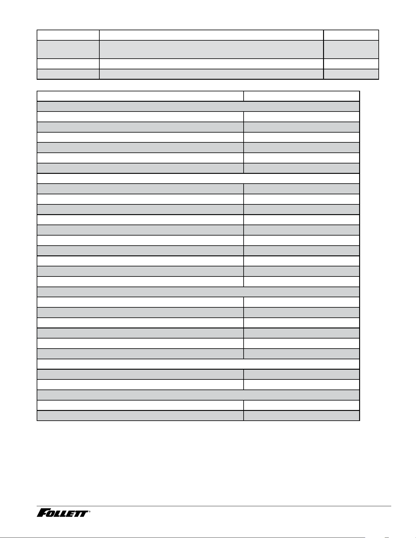
D414A/W, R414A/W, D414A/W_F, P414A/W Ice Machines 45
Miscellaneous
Reference # Description Part #
Not shown Diverter plate (single agitator Cornelius dispensers and left-hand
dispense chute on dual-agitator Cornelius dispensers)
307277
Not shown Diverter plate (right-hand dispense chute on dual-agitator dispensers) 00996207
Not shown Diverter plate, Cornelius Flavor Fusion 01100825
Replacement ice machine ordering matrix
Dispenser models Replacement ice machine model
Dispensers with top mounted ice machines
50CT414A & 50HT414A P414A
50HT414W & 50HT414W P414W
25CT 414A & 25HT414A P414A
25CT414W & 25HT414W P414W
110CT414A P414A
110CT414W P414W
Dispensers with remote ice machines
25CR414A & 25HR414A R414A
25CR414W & 25HR414W R414W
50CR414A & 50HR414A R414A
50CR414W & 50HR414W R414W
110CR414A R414A
110CR414W R414W
All U150/VU155 series with air-cooled ice machines MCD414AVS
All U150/VU155 series with water-cooled ice machines MCD414W
All VU300 series with air-cooled ice machines MCD414A
All VU300 series with water-cooled ice machines MCD414W
Freestanding dispensers with ice machines in the base
25FB414A P414A
25FB414W P414W
50FB414A P414A
50FB414W P414W
110FB414A P414A
110FB414W P414W
Nugget ice machine on top of bin
MCD425ABT D414AT*
MCD414WBT D414WT*
Flake ice machine on top of bin
MFD425ABT D414ATF*
MFD425WBT D414WTF*
* New bin top required.
46 D414A/W, R414A/W, D414A/W_F, P414A/W Ice Machines
Ice machine cleaner
01149954 SafeClean Plus liquid, case of 6
01149962 SafeClean Plus liquid, case of 24
00131524 Sponge, sanitary, each
Miscellaneous
Part # Description
01151950 Kit, Universal RIDE D414
501860 Condensate pump
502775 Oil, gearmotor, 1 pint
501111 Grease, Mobile FM 222, 14 oz tube
500377 Clamp, ice tube
501425 Grille
01075431 Sponge, sanitary, pack of 24

D414A/W, R414A/W, D414A/W_F, P414A/W Ice Machines 47

01570225R00
© Follett Products, LLC 2/25
801 Church Lane • Easton, PA 18040, USA
Toll free (877) 612-5086 • +1 (610) 252-7301
www.follettice.com
Calgon is a licensed trademark distributed by Nu-Calgon, in the United States.
3M is a trademark of 3M Company.
SafeCLEAN, SaniSponge, and Symphony Plus are trademarks of Follett Products, LLC.
Follett is a registered trademark of Follett Products, LLC, registered in US.
Warranty Registration and Equipment Evaluation
Thank you for purchasing Follett ® equipment. Our goal is to deliver high value products and services that earn your complete
satisfaction by delivering high-value products and services backed by outstanding customer and technical support.
Please review the installation instructions thoroughly. It is important that the installation be performed to factory specications so
your equipment operates at its maximum efficiency.
Follett LLC will not be liable for any consequential damages, expenses, connecting or disconnecting charges, or any losses
resulting from a defect of the machine. For full warranty details, visit our website www.follettice.com/productwarranties.
Registering your equipments helps Follett track your equipment's service history should you need to contact us for technical
support, and your feedback helps us improve our products and services. Please visit www.follettice.com/support to complete
the Warranty Registration form.
Should you have any questions, please contact Follett's technical support group at (877) 612-5086 or (610) 252-7301 and we
will be happy to assist you.