MCD425A/W_S
R425A/W
MCD425A/W_T
MFD425A/W_T
P425A/W
01033646R06
801 Church Lane • Easton, PA 18040, USA
Toll free (877) 612-5086 • +1 (610) 252-7301
www.follettice.com
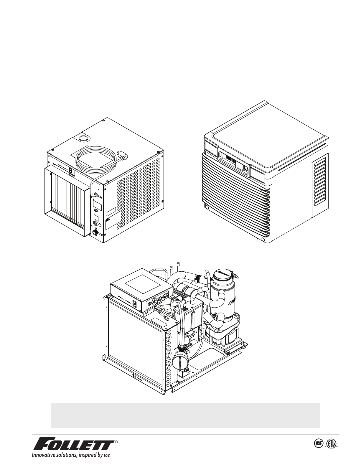
Operation and Service Manual
MCD425A/W, R425A/W, MFD425A/W, P425A/W
Ice Machines
Following installation, please forward this manual
totheappropriate operations person.
Serial numbers below K39864

2 MCD425A/W, R425A/W, MFD425A/W, P425A/W Ice Machines

MCD425A/W, R425A/W, MFD425A/W, P425A/W Ice Machines 3
Contents
Welcome to Follett. . . . . . . . . . . . . . . . . . . . . . . . . . . . . . . . . . . . . . . . . . . . . . . . . . . . . . . . . . . . . . . . . . . . . . . . . . . 4
Before you begin ............................................................................ 4
Specications .............................................................................. 5
Electrical ................................................................................ 5
Plumbing ................................................................................ 5
Ambient ................................................................................. 5
Water usage (water-cooled condenser only) .................................................... 5
Dimensions and clearances ................................................................. 6
Operation .................................................................................. 7
Cleaning/descaling and sanitizing ............................................................ 7
Weekly ................................................................................. 7
Monthly ................................................................................. 7
Semi-Annually (more often if conditions dictate) ................................................. 7
Service .................................................................................... 9
Ice machine Operation (all models) ........................................................... 9
Water system ........................................................................... 10
Electrical system ..........................................................................11
Technical specications (all models) ......................................................... 13
Electrical control system schematic .......................................................... 14
Electrical control system operation ........................................................... 15
Refrigeration system (all models) ............................................................ 24
Replacement parts ......................................................................... 27
Replacement ice machine ordering matrix ..................................................... 27
Air-cooled skins assembly (MCD425A_S, R425A) .............................................. 28
Water-cooled skins assembly (MCD425W_S, R425W) ........................................... 29
Louvered docking station (MCD425A/W_T) .................................................... 30
Electrical components .................................................................... 31
Evaporator ............................................................................. 32
Air-cooled ice machines ................................................................... 34
Water-cooled ice machines. . . . . . . . . . . . . . . . . . . . . . . . . . . . . . . . . . . . . . . . . . . . . . . . . . . . . . . . . . . . . . . . . 36
Welcome to Follett
Follett equipment enjoys a well-deserved reputation for excellent performance, long-term reliability and outstanding
after-the-sale support. To ensure that this equipment delivers that same degree of service, we ask that you review
the installation portion of this manual before beginning to install the unit. Our instructions are designed to help you
achieve a trouble-free installation. Should you have any questions or require technical help at any time, please call
our technical service group at (877) 612-5086 or +1 (610) 252-7301.
Note: To expedite assistance, all correspondence or communication MUST include the model number, serial number
and complete and detailed explanation of the problem.
Before you begin
After uncrating and removing all packing material, inspect the equipment for concealed shipping damage. If damage
is found, notify the shipper immediately and contact Follett Corporation so that we can help in the ling of a claim,
if necessary.
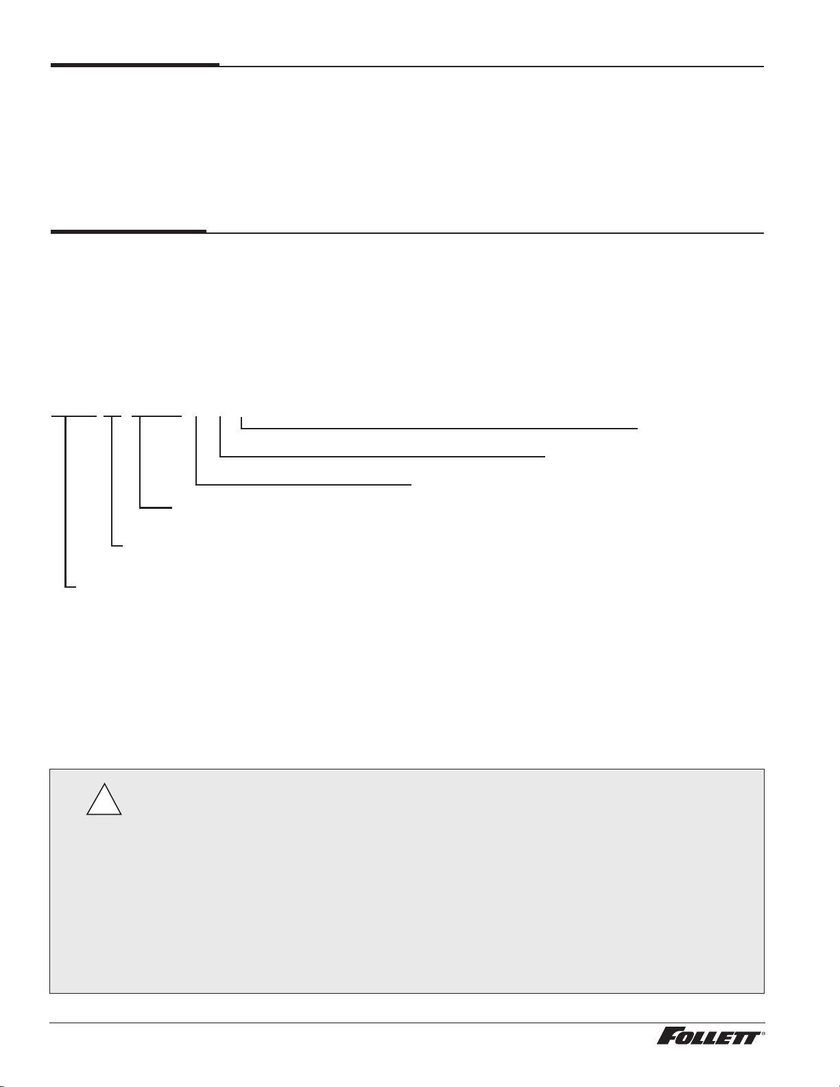
Check your paperwork to determine which model you have. Follett model numbers are designed to provide
information about the type and capacity of Follett equipment. Following is an explanation of the different model
numbers in the 425 series.
Important cautions
Moving parts. Do not operate with front cover removed.
Hot parts. Do not operate with cover removed.
To reduce risk of shock disconnect power before servicing.
Most ice machine cleaners contain citric or phosphoric acid, which can cause skin irritation. Read caution label
on product and follow instructions carefully.
Ice is slippery. Maintain counters and oors around dispenser in a clean and ice-free condition.
Ice is food. Follow recommended cleaning instructions to maintain cleanliness of delivered ice.
!
MCD425ABT
Application
V – Vision
B – Bin
H – Harmony
Configuration
S – RIDE
®
T – top-mount
Ice machine capacity and refrigerant
400 – 425 lbs (193 kg)/day, R404A
Ice machine series
Nugget ice machine
Voltage
D – 115V 60Hz
Condenser type
A – air-cooled
W – water-cooled
MCD – RIDE model installation, Vision
™
ice and beverage dispensers and top installation, Follett ice storage bins
R – Remote installation, Symphony
™
ice and water dispensers
P – Replacement icemaker, Symphony ice and water dispensers
Flake ice machine
MFD – Top installation, Follett ice storage bins
4 MCD425A/W, R425A/W, MFD425A/W, P425A/W Ice Machines
Specications
Electrical
§ Each ice machine and dispenser require a separate circuit with electrical disconnect within 10 ft (6 m).
§ Equipment ground required.
§ Standard electrical – 115 V, 60 Hz, 1 phase.
§ Connect to a dedicated 15A circuit.
§ Maximum ice machine amperage – 11A each.
§ Cord and plug provided on ice machine.
Plumbing
§ 3/8" FPT water inlet
§ 3/4" MPT drain
§ 3/8" FPT condenser inlet (water-cooled condenser only)
§ 3/8" FPT condenser drain (water-cooled condenser only)
Notes:
§ Slope to drain of 1/4" per foot (6 mm per 30.4 cm run) with a 1/2" min. is recommended.
§ Water shut-off recommended within 10 feet (3 m), drain to be hard piped and insulated.
§ Separate drains for ice machine and condenser. To prevent back ow, do NOT connect drains.
§ Follett recommends a Follett water lter system be installed in the ice machine inlet water line (standard capacity
#00130229, high capacity #00978957, carbonless high capacity #01050442).
Ambient
Air temperature* 100 F/38 C max. 50 F/10 C min. (best performance below 80 F/27 C)
Water temperature
†
90 F/32 C max. 45 F/10 C min. (best performance below 70 F/21 C)
Water pressure 70 psi max. (482 kPA) 10 psi min. (68 kPA)
Condenser water
temperature
90 F/32.2 C max. 45 F/7.2 C min
Condenser water
pressure
125 psi (862 kPA) max. 10 psi (68 kPA) min.
*
Ambient air temperature is measured at the air-cooled condenser coil inlet.
†
Ambient water temperature is measured in the ice machine reservoir.
Water usage (water-cooled condenser only)
§ 0.25 gpm @ 50 F (10 C)
§ 0.5 gpm @ 70 F (21 C)
§ 1.25 gpm @ 90 F (32 C)
MCD425A/W, R425A/W, MFD425A/W, P425A/W Ice Machines 5
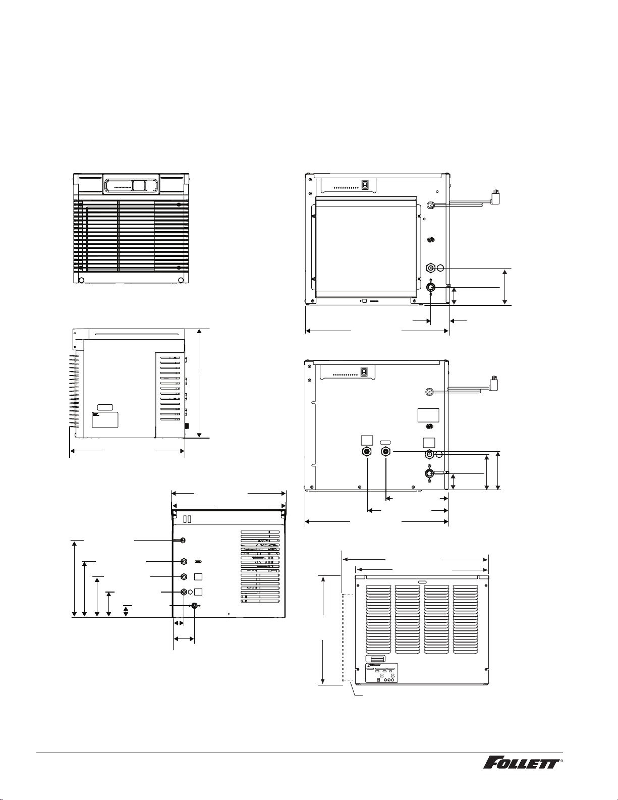
Side view — air-cooled and water-cooled
20.75" (52.7 cm)
22.75" (57.8 cm)
17.00"
(43.2 cm)
RIDE model air-cooled units only
Front view — top mount
MCD425A/W_T
MFD425A/W_T
MCD425A/W_S
R425A/W
Side view — top mount
22.49" (57.1 cm)
21.29" (54.1 cm)
22.69" (57.6 cm)
22.46" (57.1 cm)
Back view — top mount
A
B
D
E
C
Front view — water-cooled
CONDENSER
OUTLET
10.62" (27.0 cm)
8.25" (20.9 cm)
4.81"
(12.0 cm)
2.31"
(5.7 cm)
5.25"
(13.3 cm)
C
F
E
D
A
B
Front view — air-cooled
4.81"
(12.0 cm)
2.31" (5.7 cm)
2.5" (6.4 cm)
C
F
A
B
18.88" (48 cm)
18.88" (48 cm)
2.32"
(5.9 cm)
4.40" (11.2 cm)
15.22" (38.7 cm)
11.03" (28.0 cm)
8.03" (20.4 cm)
5.03" (12.8 cm)
2.34" (6 cm)
Dimensions and clearances
§ Entire front of ice machine must be clear of obstructions/connections to allow removal.
§ 12" (30.5 cm) clearance above ice machine for service.
§ 6" (15.3 cm) minimum clearance between exhaust side of ice machine and any adjacent equipment.
§ MCD425A & R425A – 18" (45.7 cm) minimum, 10 ft (3 m) maximum clearance between discharge and air
intake grilles.
A – 3/4" MPT drain
B – 3/8" FPT water inlet
C – Electrical cord
D – 3/8" FPT condenser inlet
E – 3/8" FPT condenser drain
F – Bin signal connection (DO NOT APPLY VOLTAGE!)
6 MCD425A/W, R425A/W, MFD425A/W, P425A/W Ice Machines
Operation
Cleaning/descaling and sanitizing
Follett ice machines and dispensers, and their associated cleaning and sanitizing procedures, are designed for
use with potable water sources. The presence, or suspected presence, of infectious agents may call for additional
measures, including the replacement of components and more comprehensive disinfection measures. Follett
recommends that these cleaning and sanitizing procedures be reviewed with the appropriate infectious agent subject
matter experts to assure complete remediation.
Periodic cleaning/descaling and sanitizing of Follett’s ice machine system is required to ensure peak performance
and delivery of clean, sanitary ice. The recommended cleaning procedures that follow should be performed at least
as frequently as recommended and more often if environmental conditions dictate.
Cleaning of the condenser can usually be performed by facility personnel. Cleaning/descaling and sanitizing of
the ice machine system should be performed by your facility’s trained maintenance staff or a Follett authorized
service agent. Regardless of who performs the cleaning, it is the operator’s responsibility to see that this cleaning is
performed according to the schedule below. Service problems resulting from lack of preventive maintenance will not
be covered under the Follett warranty.
Symphony Plus Frequency
Drain Line weekly
Drain Pan/Drip Pan weekly
Exterior, Water Station Tube as needed
Condenser monthly (air-cooled only)
Ice Machine semi-annually
Transport Tube semi-annually
* Ice machine must be sanitized prior to start-up.
Weekly
The exterior may be cleaned with a stainless cleaner such as 3M* Stainless Steel Cleaner & Polish or equivalent.
* 3M is a trademark of 3M Company.
Monthly
Condenser (air-cooled ice machine only)
1. Use a vacuum cleaner or stiff brush to carefully clean condenser coils of lint and debris to ensure optimal
performance.
2. When reinstalling counter panels in front of RIDE model ice machines, be sure that ventilation louvers line
up with condenser air duct.
Semi-Annually (more often if conditions dictate)
§ A cleaning/descaling and sanitizing procedure should always include both the ice machine and bin/dispenser.
§ Icemaking system can be cleaned/descaled in place.
Cleaning & Sanitizing Tool Checklist
§ (2) 1.5 gallon (or larger) plastic buckets
§ (2) clean cloths
§ Sanitary gloves
§ Safety glasses
§ (2) Sani-Sponge™ (P/N 00131524 - single sponge)
§ (1 ) Packet of SafeCLEAN™ (P/N 00132001 - 24 packets)
§ 1.6 oz. of Nu-Calgon IMS-II or IMS-III Sanitizer (P/N 00979674 - 16 . oz. bottle)
MCD425A/W, R425A/W, MFD425A/W, P425A/W Ice Machines 7
CAUTION!
§ Wear rubber gloves and safety goggles (or face shield) when handling cleaner or sanitizer mixtures.
§ Use only Follett approved cleaners.
§ It is a violation of Federal law to use the Cleaning or Sanitizing solution in a manner inconsistent with their
labeling.
§ Do not use solvents, abrasive cleaners, metal scrapers or sharp objects to clean any part of the dispenser.
Cleaning Solution: Mix cleaning solution of 1 gal. (3.8 L) 100 F (38 C) water and 7 oz. (198 g) (one 7 oz. packet) of
Follett SafeCLEAN ice machine cleaner/descaler (P/N 00132001).
Sanitizing Solution: Mix a sanitizing solution of 1 gal. (3.8 L) 100 F (38 C) water and 1.6 oz. (47 ml) Nu-Calgon IMS-II or
IMS-III Sanitizer (P/N 00979674).
Cleaning/descaling procedure
Note: Check drains and drain cup to ensure they are open and owing freely.
1. If ice machine was running recently, ensure that the evaporator is completely free of ice before proceeding.
If there is ice in the evaporator, complete steps 2-7 using only hot water to remove the ice then begin
Cleaning/Descaling Procedure again.
2. Remove front or top cover.
3. Disconnect bin signal cable from ice machine electrical box.
4. Press CLEAN switch. The MAINTENANCE light will turn on and the machine will drain. Wait for the LOW
WATER light to turn on.
5. Remove lid from cleaning cup and ll (about 1 quart) until cleaning solution completely lls the reservoir.
Place lid back on cup.
6. CLEANER FULL light will turn on and machine will start cleaning cycle then rinse three times; this process
takes approximately 15 minutes.
7. When machine is nished cleaning, the MAINTENANCE light will turn off.
Sanitizing Procedure
8. Press CLEAN switch. The MAINTENANCE light and LOW WATER light will turn on.
9. Fill cleaning cup with sanitizing solution until completely lls the reservoir. Place lid back on cup. Save
remainder of sanitizing solution.
10. CLEANER FULL light will turn on and machine will start sanitizing cycle then rinse three times; this
process takes approximately 15 minutes.
11. When machine is nished rinsing, the MAINTENANCE light will turn off. Remove top bearing insulation and
nozzle insulation, then loosen phillips-head screw on nozzle connected to evaporator. Remove nozzle from
evaporator side only, leave other side of nozzle connected to transport tube.
12. Place one Sani-Sponge in remaining sanitizing solution.
13. Insert the sponge soaked in sanitizing solution into nozzle then insert a dry sponge into the nozzle.
14. Replace nozzle onto evaporator and tighten screw. Ensure drain is connected to reservoir and vent tubes
are connected to evaporator drain pan.
15. Reconnect bin signal cable. Wait for ice to push sponges through transport tube.
16. Collect sponges from ice storage bin.
1 7. Replace front or top cover.
18. After 10 minutes, dispense all ice and discard.
19. Clean/descale and sanitize dispenser/bin.
User Interface and Exterior Cabinet
§ Clean stainless steel panels with stainless steel cleaner.
8 MCD425A/W, R425A/W, MFD425A/W, P425A/W Ice Machines
Service
Ice machine Operation (all models)
Follett’s ice machine consists of four distinct functional systems:
§ Harvesting system
§ Water system
§ Electrical control system
§ Refrigeration system
These four systems work together to accomplish the production and harvesting of ice. A problem in any one of these
systems will result in improper operation of the entire ice production cycle. When troubleshooting the ice machine,
it is important to analyze the entire system operation to determine which system is not functioning properly, then
pinpoint the component within that system that is malfunctioning. Determine what corrective action must be taken
before making any adjustments or replacing any components.
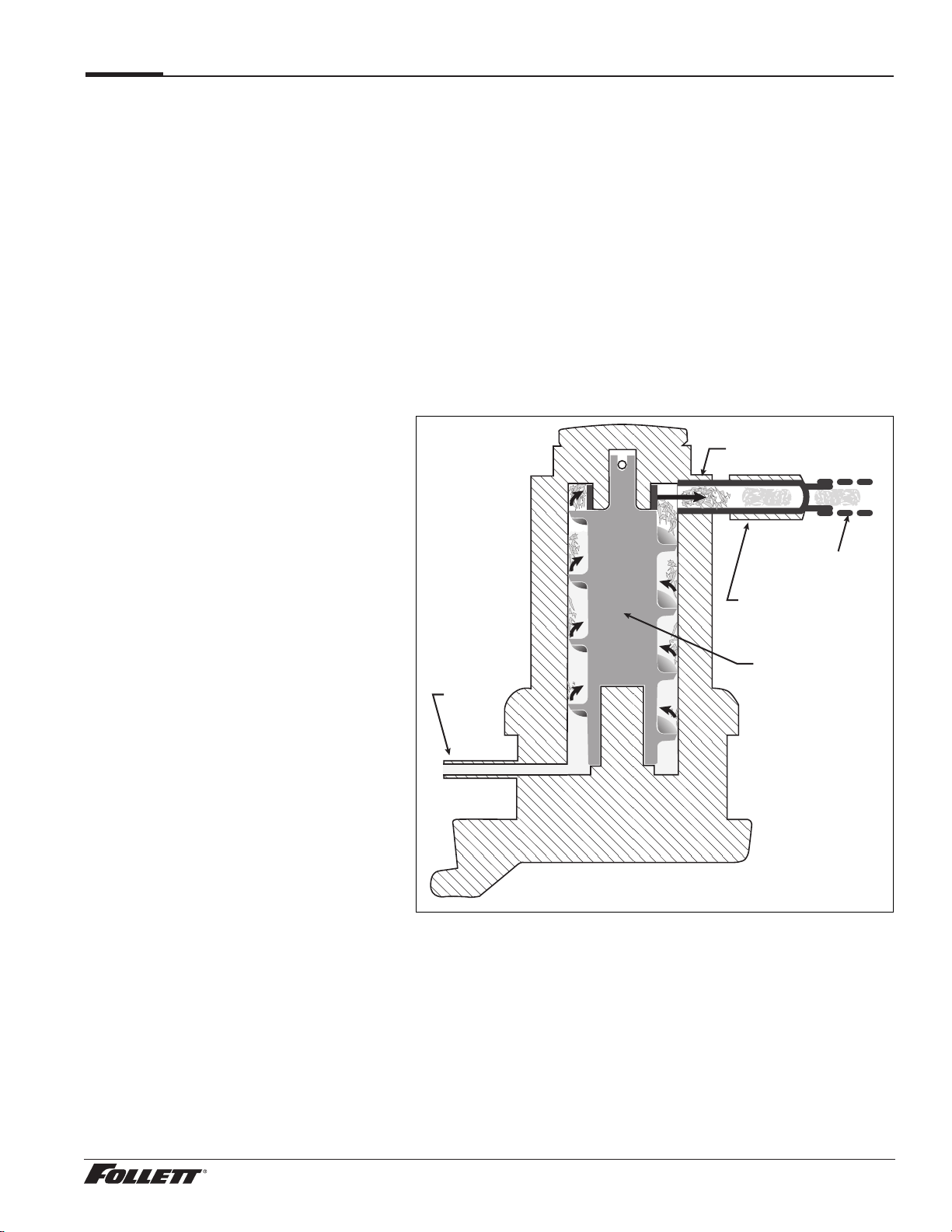
The icemaking process
The Maestro Plus ice machine uses a stainless steel jacketed evaporator and operates on a continuous freezing
cycle. Water is supplied to the evaporator from the water reservoir where the water level is controlled by a oat valve.
This valve also shuts off the water supply when the ice machine is not running.
When the ice machine is running, a layer
of ice forms on the interior surface of the
evaporator. This ice is continuously removed
by a slowly rotating (12RPM) auger. The
auger carries the ice upward into the cavity
formed by the top bearing housing and the
compression loop, where it is compressed to
remove excess water. When the ice reaches
the desired hardness it rotates within the
cavity and is forced through a discharge
port and compression nozzle and into the
ice transport tube. The discharge tube and
compression nozzle are slightly restricted to
further compress the ice and produce the
desired hardness.
A solid state control board located in the
electrical box of the ice machine controls
the normal operation of the ice machine
and monitors gearmotor torque. This control
board will shut down the ice machine should
an over-torque condition occur. It is very
important that you familiarize yourself with
the operational sequences detailed in this
manual before attempting to service the ice
machine.
water
inlet
auger
compression nozzle
ice transport tube
evaporator
port
MCD425A/W, R425A/W, MFD425A/W, P425A/W Ice Machines 9
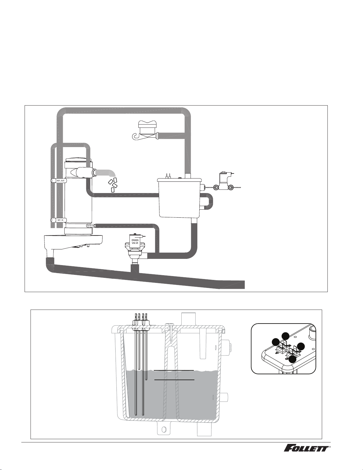
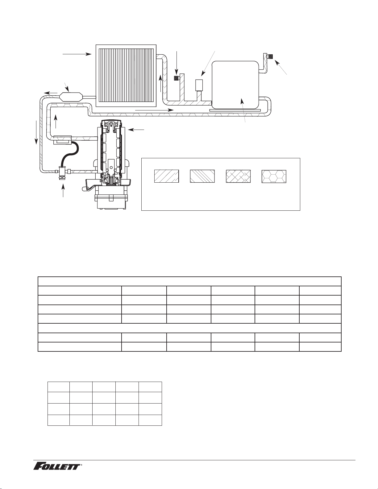
Water system
The water level in the evaporator is controlled by a ll solenoid (Fig 1) and level detecting sensors. Water sensing
rods (Fig. 2) extend down into the reservoir at the end of the evaporator assembly. The system works via electrical
conductivity as follows:
One of the longest probes is a common. When water is between any of the other probes and the common, the
PC board will sense the activation. During normal operation, the water level rises and falls between the Normal
High and Normal Low sensors. As water is consumed to make ice, the level will fall until the Normal Low sensor is
exposed, triggering the water feed solenoid on. Water will ll until the Normal High sensor is activated.
Note: The potable water dissolved solids content must be greater than 10 ppm for the water control system to
function properly. If using reverse osmosis water ltration system, ensure T.D.S level is greater than 10 ppm.
Fig. 1 Water system diagram
CLEANING CUP
WATER SUPPLY
3/8" FPT, 45-90 F (7-32 C)
10-70 PSI (69-483 KPA)
RESERVOIR FILL
SOLENOID
WASTE WATER DRAIN
3/4" FPT
WATER
RESERVOIR
EVAPORATOR
ICE
NOZZLE
DRAIN PAN
VENT
DRAIN
Fig. 2 Water level diagram
B
A
C
D
NORMAL OPERATING RANGE
A ALARM LOW (RED)
B COMMON (BLACK)
C NORMAL HIGH (ORANGE)
D NORMAL LOW (YELLOW)
B
A
B
A
C
D
C
D
10 MCD425A/W, R425A/W, MFD425A/W, P425A/W Ice Machines
MCD425A/W, R425A/W, MFD425A/W, P425A/W Ice Machines 11
Electrical system
ATTENTION!
To prevent circuit breaker overload, wait 15 minutes before restarting this unit. This allows the compressor
to equalize and the evaporator to thaw.
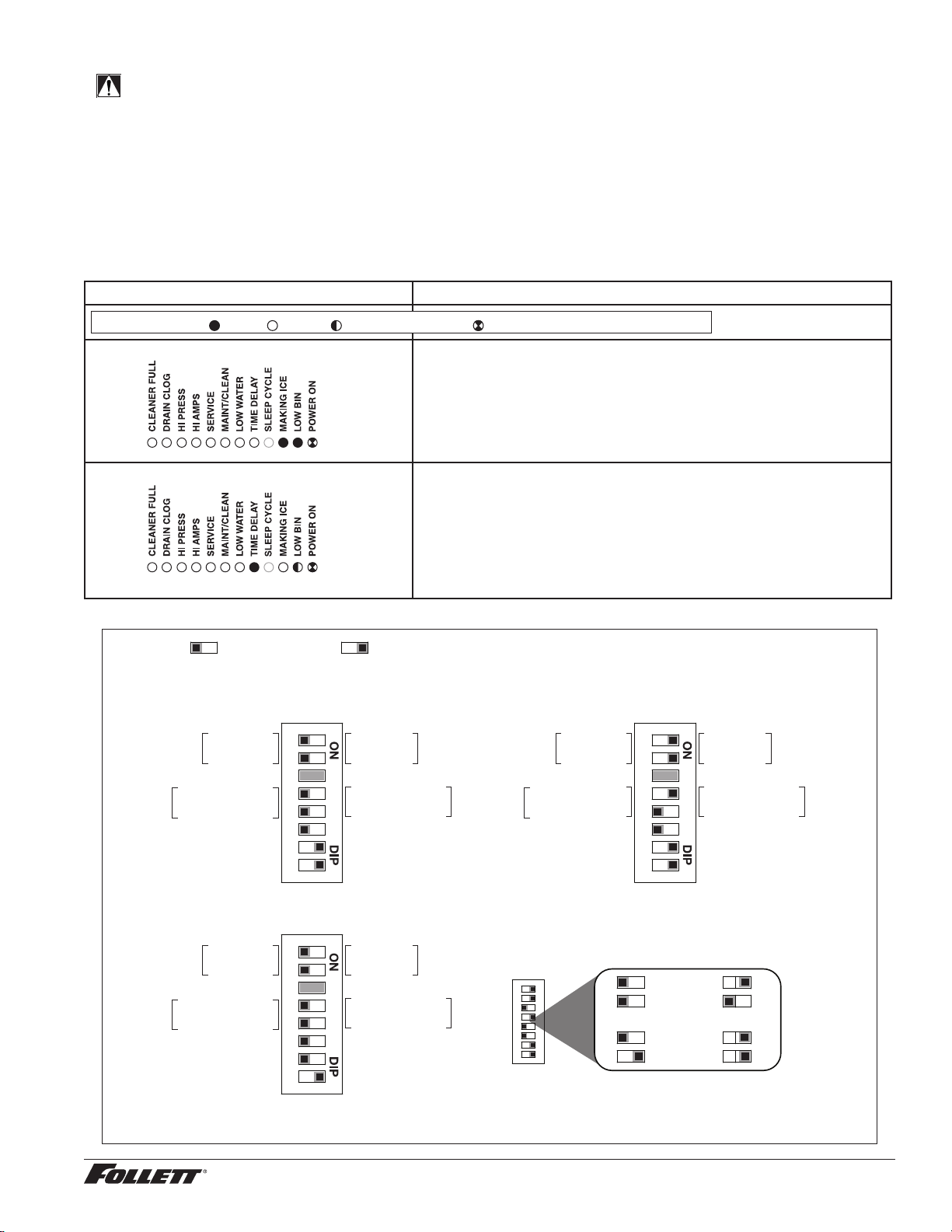
Normal control board operation
The PC board indicator lights provide all the information necessary to determine the machine's status. Green
indicator lights generally represent “go” or normal operation; Yellow indicators represent normal off conditions; Red
indicators generally represent alarm conditions, some of which will lock the machine off.
A ashing green light labeled POWER indicates power to the machine. All other normal operation status indicators
are covered as follows:
Ice machine disposition Operating conditions
FLASHINGON or OFF
Legend:
OFFON
1. Ice machine is making ice. 1. Normal running.
2. Ice machine is not making ice.
2. Normal time delay. When the bin lls with ice, the LOW BIN
light goes out momentarily and the refrigeration and auger
drive systems immediately shut down. (Note: The fan motor
will continue to run for 10 minutes to cool condenser) The TIME
DELAY light comes on, initiating the time delay period. When
the time delay expires, the machine will restart provided that the
LOW BIN light is on.
DIP Switch Settings
Sleep cycle dispense duration
OFF ON
1 2 3 4 5 6 7 8
4 5 4 5
4 5 4 5
35 s
15 s
5 s
60 s
OFF POSITION ON POSITION
Sleep cycle
enabled
Not used
Sleep cycle
dispense duration
60 min. time delay
Flush enabled*
Maint. timer OFF
OFF ON
Sleep cycle
disabled
Not used
Sleep cycle
dispense duration
20 min. time delay
Flush disabled
Maint. timer ON
1 2 3 4 5 6 7 8
Sleep cycle
enabled
Not used
Sleep cycle
dispense duration
60 min. time delay
Flush enabled
Maint. timer OFF
OFF ON
Sleep cycle
disabled
Not used
Sleep cycle
dispense duration
20 min. time delay
Flush disabled
Maint. timer ON
MCD425A/W_T, MCD425A/W_S, R425A/W
Replacement P425A/W installed in Symphony dispenser
Sleep cycle
enabled
Not used
Sleep cycle
dispense duration
60 min. time delay
Flush enabled
Maint. timer OFF
OFF ON
Sleep cycle
disabled
Not used
Sleep cycle
dispense duration
20 min. time delay
Flush disabled
Maint. timer ON
425A/W installed in Symphony Plus
25/50/110 CI, CT, or FB
* Flush can be enabled on Symphony CT and FB models. Flush should be disabled on Symphony CI units due to risk of internal leak if
drain line is blocked. All Symphony Plus models should be set to Flush enabled.
1 2 3 4 5 6 7 8
1 2 3 4 5 6 7 8

12 MCD425A/W, R425A/W, MFD425A/W, P425A/W Ice Machines
Relay/triac output indication
Each relay on the board has an indicator light associated with its output. For example, when the relay for the water
feed solenoid is energized, the adjacent indicator light glows green.
Flushing logic
Off cycle: At the completion of off-cycle time delay, the machine checks for a cumulative one (1) hour of ice making
time since the last off-cycle ush. If the cumulative ice making time exceeds one (1) hour, the machine will open
the drain valve for 60 seconds to drain the evaporator in its entirety. It will then rell with water, ush again and rell,
and begin making ice. If the ice making time is less than 1 hour, the machine will start and begin making ice without
draining the evaporator.
Error faults
The Maestro Plus PC board monitors various operating parameters including high pressure, auger gearmotor
amperage limits, clogged drain, and low water alarm conditions. There are two types of errors namely “hard” or “soft”.
A hard error is one that shuts the machine off and will not allow restart until the reset button is pressed. Even cycling
power will not reset a hard error. A soft error can either be automatically reset should the condition rectify, or if power
is cycled. Should an error occur, consult the troubleshooting guide in this manual or a Follett service technician.
Soft errors:
Note: For all soft errors, the ice machine will remain off for 1 hour.
LO WATER: During operation, the water level cycles between the normal low and normal high sensors. Should the
water be shut off to a running machine, a soft error will occur. The error sequence is as follows: During operation,
the water level falls to the normal low sensor, and when it does the water feed solenoid is energized. If water is not
detected at the normal low sensor within 10 seconds, a soft error will occur. The machine will shut down and TIME
DELAY and LOW WATER LEDs will be lit. After time delay, the solenoid will energize and remain energized until the
water level is sufficient for restart.
HI PRESSURE: Should the refrigeration pressure rise above 425 psi, the machine will shut down and the TIME
DELAY and HIGH PRESSURE will be illuminated. After the time delay, and if the pressure has fallen back below the
reset point of 295 psi, the machine will restart and the TIME DELAY and HIGH PRESSURE will clear.
HI AMPS: The PC board monitors the amperage of the auger motor. Should the gear motor experience current draw
above the allowable 3A limit or no current draw (0A), the machine will shut down and the TIME DELAY and HI AMP
will be illuminated. After the time delay the machine will restart and the TIME DELAY and HI AMP will clear.
Hard error:
HI AMPS: If a second hi-amp error occurs within 1 hour of the initial hi-amp error, the ice machine will shut off and
the reset on the board must be pressed to clear the error. If a second hi-amp has occurred, the HI AMP LED only will
be illuminated.
DRAIN CLOG: The drain clog sensor, located in the evaporator drain pan will detect the presence of water just below
the top edge of the pan. If water does not properly ow out of the internal or external drain lines it will backup into the
drain pan (especially during a self-ushing purge cycle). Pressing the reset button will restart the ice machine.
MCD425A/W, R425A/W, MFD425A/W, P425A/W Ice Machines 13
Technical specications (all models)
Refrigeration system diagram
condenser
filter dryer
thermostatic
expansion
valve
evaporator
high side
service port
low side
service port
high pressure
switch
compressor
high
pressure
vapor
low
pressure
vapor
high
pressure
liquid
low
pressure
liquid
Refrigeration pressure data
§ Water regulating valve is factory set at 300 (±10) PSIG head pressure.
§ Readings within 10% of table values should be considered normal.
Compressor data
Locked rotor amps 58.8A
Compressor current draw
Air-cooled
Ambient air temperature 60 F/15.6 C 70 F/21.1 C 80 F/26.7 C 90 F/32.2 C 100 F/37.8 C
Amperage 6.3A 6.5A 6.7A 6.9A 7.1A
High-side pressure (psi) 190 220 250 290 330
Low-side pressure (psi) 27 29 31 33 36
Water-cooled
Water temperature at oat 50 F/10 C 60 F/15.6 C 70 F/21.1 C 80 F/26.7 C 90 F/32.2 C
5.6A 5.6A 5.7A 5.8A 5.8A
50/10
280/27
280/27
280/27
70/21
285/29
285/29
285/29
90/32
290/31
290/31
290/31
psi
psi
psi
Discharge Pressure/Suction Pressure
Water-cooled Ice Machine Refrigeration Pressure
˚F/˚C
50/10
70/21
90/32
Condenser inlet water temperature ˚F/˚C
Air-cooled Ice Machine Refrigeration Pressure
Ambient air temperature ˚F/˚C
Ice machine inlet water
temperature ˚F/˚C
Discharge Pressure/Suction Pressure
psi
psi
psi
100/38
237/37
326/38
347/40
80/27
245/31
244/30
265/32
60/16
174/23
174/23
190/25
˚F/˚C
50/10
70/21
90/32
Ice machine inlet water
temperature ˚F/˚C
Gearmotor data Split-Phase PSC (permanent split capacitor)
Gearmotor current 1.8A-1.9A (nominal) 0.8A-0.9A (nominal)
Locked rotor amps 14A 7A-14A (temperature dependent)
14 MCD425A/W, R425A/W, MFD425A/W, P425A/W Ice Machines
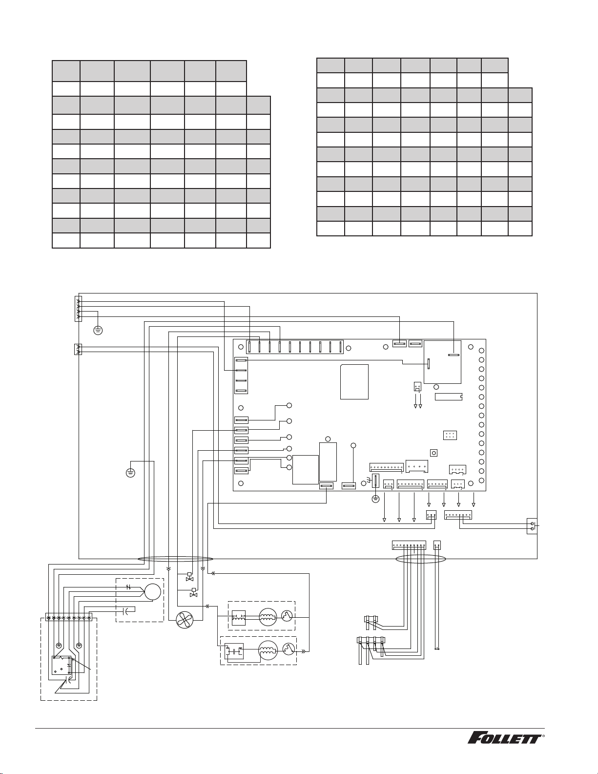
Electrical control system schematic
WATER LEVELS
P17
BIN
P12
CLEAN SAFE
P11
POWER
LOW BIN
MAKING ICE
SLEEP CYCLE
TIME DELAY
LOW WATER
MAINTENANCE
SERVICE
HI AMPS
HI PRESSURE
CLEANER FULL
RESERVOIR
WATER SENSOR
MAINT.
CLEAN
HI PRS
P14
HIGH
PRESS
P
A B C D
BLACK
YELLOW
ORANGE
RED
GRN #17
BLACK #51
BLACK #23
BIN
CONTACT
CLOSURE
L1
L2/N
DISP
GND
BLACK #23
GRN-YEL #24
WHITE #25
BLACK #26
WHITE
BLUE
SPLIT-PHASE
START
RELAY
3
4
2
YELLOW
BLACK
T.O.L.
START
RUN
FAN
FEED VALVE
DRAIN VALVE
RED #16
WHITE #121
WHITE #13
BROWN #14
BLACK #122
BLUE #07
BLACK #51
WHITE #52
COMP.
R
C
S
O.L.
C2 START
1 2 3 4 5 6 7 8 9
GREEN #53
COMPRESSOR
COMPRESSOR
ELECTRICAL
BOX
BLACK #51
WHITE #52
GREEN #53
RED #54
ORANGE #55
BLACK #56
GREEN #57
BLACK #58
BLACK #59
6
4
1
2
5
BLACK #61
WHITE #62
GREEN #63
WHITE #64
BLACK #65
BLACK #66
GREEN #67
BLACK #68
BLACK #69
C1 RUN
BLACK #66
BLACK #69
BLACK #71
#15
#04
#05
WHITE
DRAIN CLOG
SENSOR
BLACK
VIOLET
DRAIN CLOG
MODEL SELECT
SERIAL COMM
COMPRESSOR
AUGER
WATER LEVELS
HI PRS
BIN RS485
RS485 UI
CURRENT SENS
RESET
PROGRAM
P5
ICE AUX WATER AUX
D9
D8
D7
D6
D5
D4
D37
D3
D2
D18
D16
D15
D14
D13
D12
D11
D10
D1
T1
P18
P11
P13
P17
P12
P14
P16
P15
P4
T2
S1
S2
K1
P7
P8
P10
K3
1
2
6
5
P9
L1 L1L1
N N N N N N N N N
P2
P1
P21
P20
P19
P3
BLACK #01
P6
P22
D19D22D21D20
D17
D48
BLACK
BLACK
BLUE
OR
CAPACITOR
T.O.L.
START
RUN
BLACK
YELLOW
PSC MOTOR
Water-Cooled ice machine capacity/24hrs.
Condenser Water Temperature F/C
Inlet Water Temperature F/C
F 50 60 70 80 90 100
C 10 16 21 27 32 38
50 486 465 443 422 400 389 lbs.
10 220 2 11 201 191 181 176 kg.
60 464 445 425 406 386 367 lbs.
16 210 202 193 184 175 166 kg.
70 443 425 408 390 372 358 lbs.
21 201 193 185 177 169 162 kg.
80 422 406 389 373 356 340 lbs.
27 191 184 176 169 161 154 kg.
90 400 385 371 356 341 326 lbs.
32 181 175 168 161 155 148 kg.
Air-Cooled ice machine capacity/24hrs.
Ambient Air Temperature F/C
Inlet Water Temperature F/C
F 60 70 80 90 100
C 16 21 27 32 38
50 460 425 390 355 320 lbs.
10 208 193 177 161 145 kg.
60 437.5 405 372.5 340 307.5 lbs.
16 198 184 169 154 139 kg.
70 415 385 355 325 295 lbs.
21 188 175 161 147 134 kg.
80 405 375 345 315 285 lbs.
27 184 170 156 142 129 kg.
90 395 365 335 305 275 lbs.
32 179 166 152 138 125 kg.
Note: Nominal values - actual production may vary by ±10%.
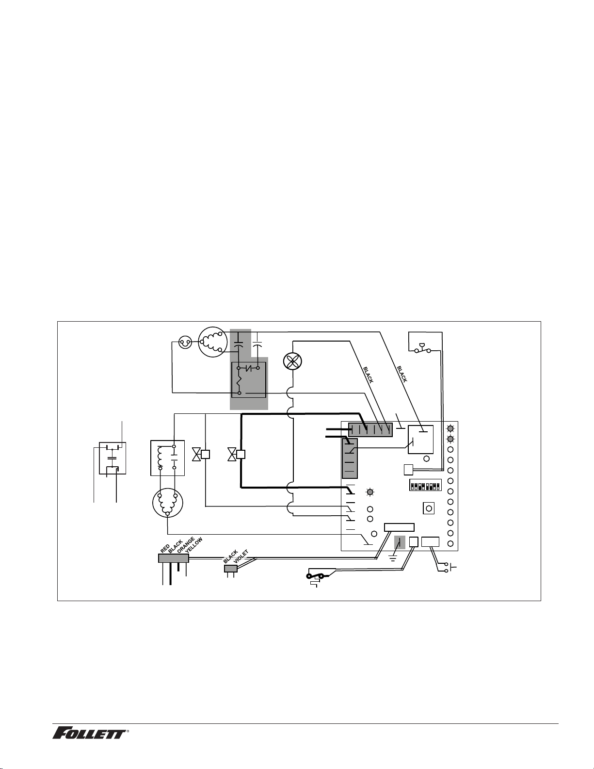
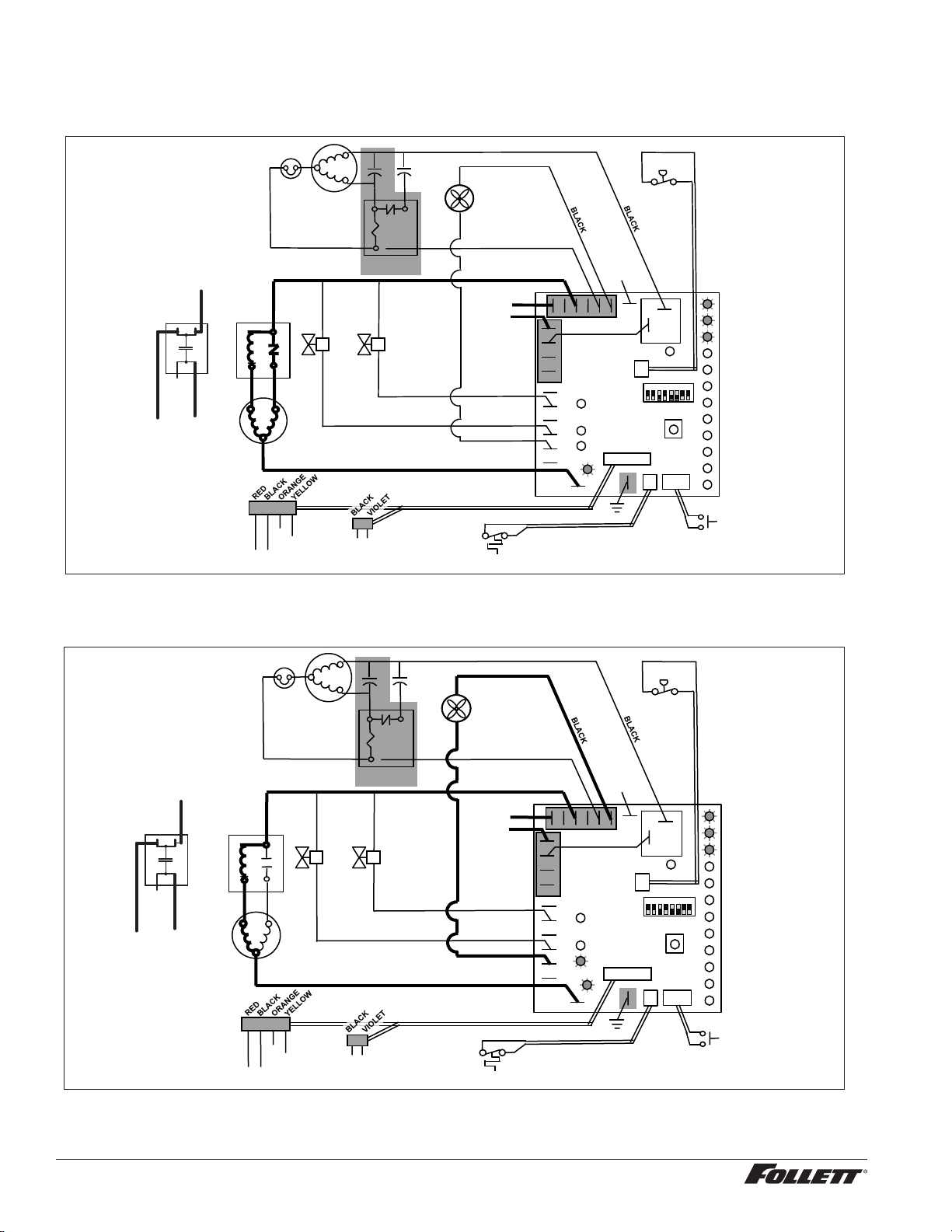
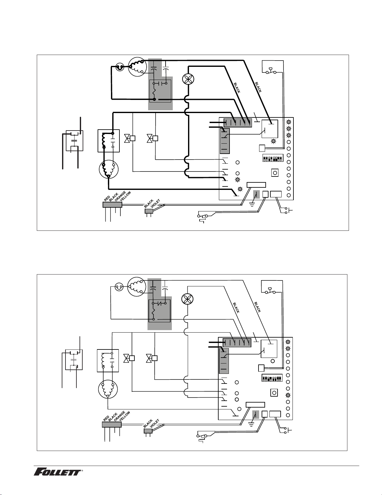
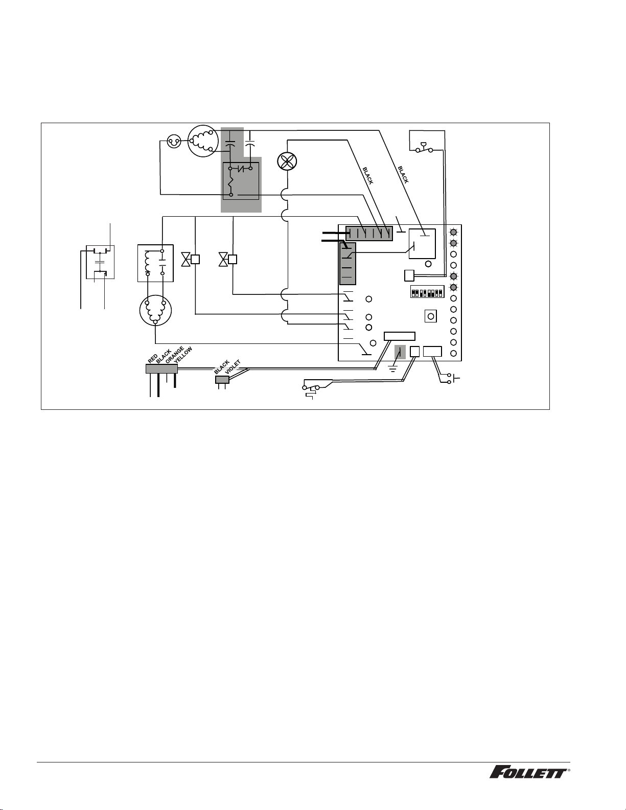
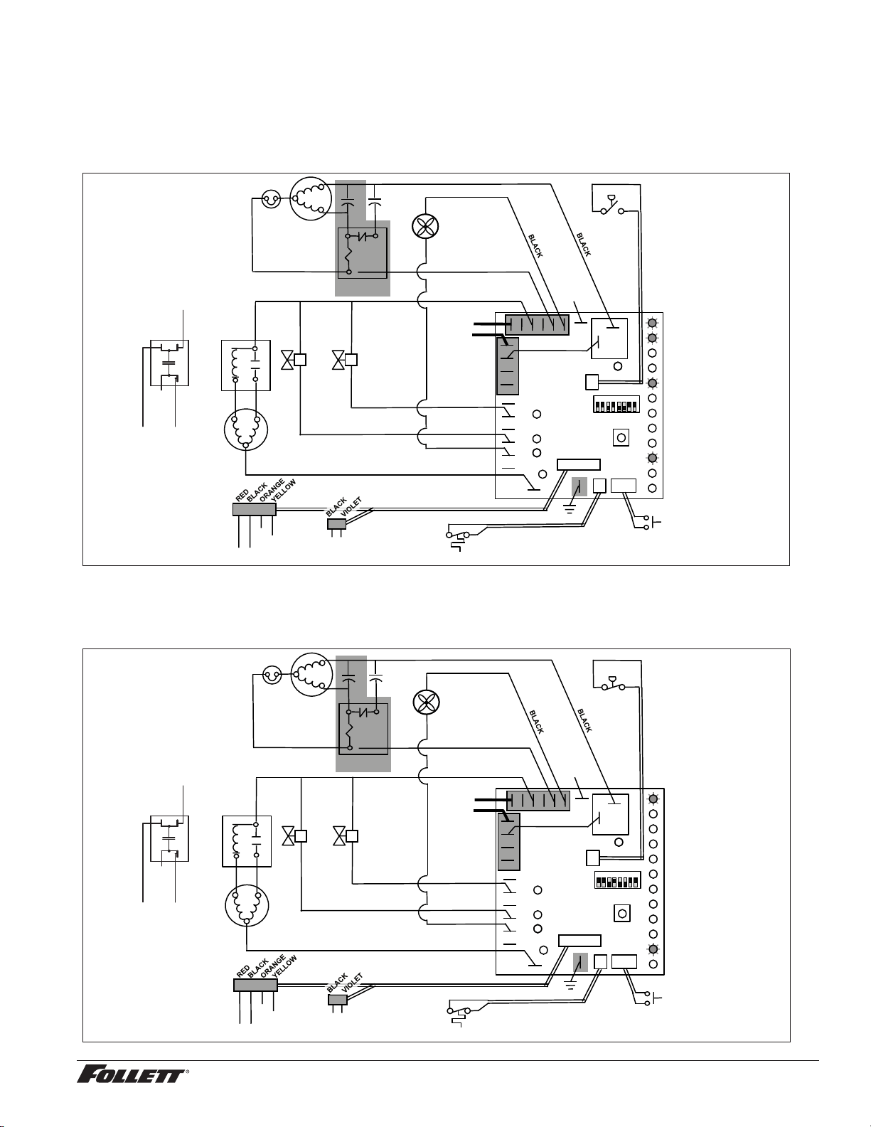
Electrical control system operation
The P425A/W, MCD425A/W_S and R425A/W wiring diagrams which follow illustrate the circuitry of Follett ice
machines used with ice dispensers. Both normal operation of the ice machine (Stages 1–6) and non-normal
diagnostic sequences showing torque-out (Stages 7–10) for use in troubleshooting ice machine problems are
shown.
Circuitry notes
When the ice machine is used with a dispenser it receives power from the main power supply. Disconnect the
power source before performing service. When performing electrical service, always use a meter to determine
whether or not the components being serviced are energized.
§ High pressure cutout opens at 425 PSI and closes at 287 PSI (auto reset).
§ The bin signal input to the control board in the 425A/W ice machine must only be initiated by contact closure. Do
not supply power. To run the ice machine in the workshop, use the bin signal jumper (P/N 01069095).
Note: The operation stage descriptions that follow are based on the unit containing the split-phase gear
motor.
Normal operation – Stage 1
Power is supplied to L1 of the control board, the POWER LED light begins ashing. The ice level bin thermostat in
the dispenser is closed and calling for ice, supplying contact closure to the control board. The LOW BIN LED will
be on. The control board will now go through the start-up sequence. The board checks the water sensors (located
in the reservoir) for continuity between the common probe (B) and the high probe (C). If continuity is not sensed,
the water ll valve (P21) is energized.
5
2
1
Start
Run
Compressor
T.O.L.
MAINTENANCE
LOW WATER
TIME DELAY
SLEEP CYCLE
MAKING ICE
LOW BIN
POWER
SERVICE
HI AMPS
HI PRESSURE
DRAIN CLOG
CLEANER FULL
High
Pressure
Switch
R
S
C
Gearmotor
Start
Relay
Start
Relay
N
L1
Fan
A B C D
Water Sensors
RESET
Fill
Valve
Drain
Valve
3
4
2
Bin T-Stat
Clean Switch
Drain Clog Sensor
P6
P21
P20
P19
P3
P22
P4
AUGER
WATER LEVELS
BIN
P11
HI PRS
L1
R
S
C
RED
WHITE
WHITE
BLACK
BROWN
BLUE
RED
BLACK YELLOW
Compressor
Electrical Box
COMPRESSOR
1 2 3 4 5 6 7 8
BLACK
N
P15
Ice Dispense Input
Capacitor
BLACK
YELLOW
OR
NO CONNECT
MCD425A/W, R425A/W, MFD425A/W, P425A/W Ice Machines 15
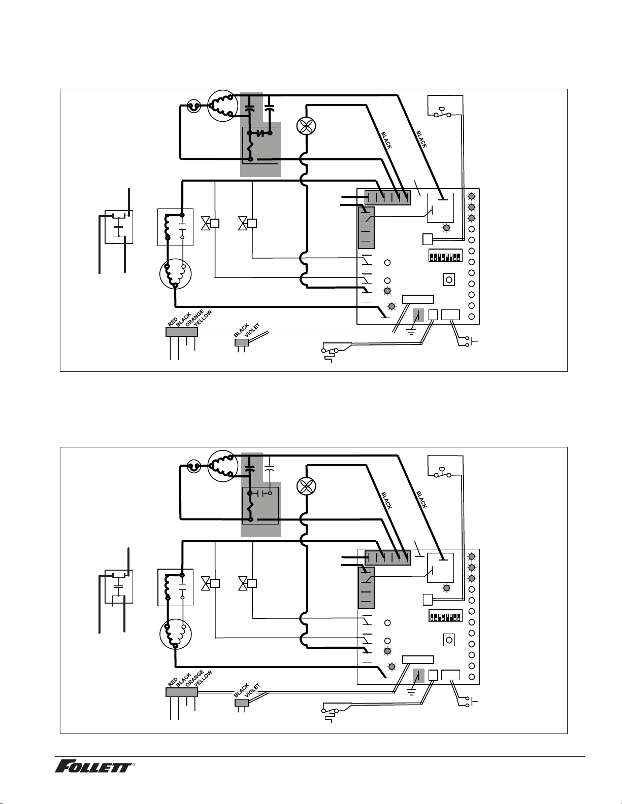
Normal operation – Stage 2
When continuity is seen between B and C, the water valve de-energizes, the AUGER output (P4) comes on along
with the MAKING ICE LED. The auger gearmotor’s start windings are energized through a current style start relay
that is pulled in by the initial high current draw of the gearmotor.
5
2
1
Start
Run
Compressor
T.O.L.
MAINTENANCE
LOW WATER
TIME DELAY
SLEEP CYCLE
MAKING ICE
LOW BIN
POWER
SERVICE
HI AMPS
HI PRESSURE
DRAIN CLOG
CLEANER FULL
High
Pressure
Switch
R
S
C
Gearmotor
Start
Relay
Start
Relay
N
L1
Fan
A B C D
Water Sensors
RESET
Fill
Valve
Drain
Valve
3
4
2
Bin T-Stat
Clean Switch
Drain Clog Sensor
P6
P21
P20
P19
P3
P22
P4
AUGER
WATER LEVELS
BIN
P11
HI PRS
L1
R
S
C
RED
WHITE
WHITE
BLACK
BROWN
BLUE
RED
BLACK YELLOW
Compressor
Electrical Box
COMPRESSOR
1 2 3 4 5 6 7 8
BLACK
N
P15
Ice Dispense Input
Capacitor
BLACK
YELLOW
OR
NO CONNECT
PSC: Start winding
energized through
capacitor.
Normal operation – Stage 3
After the initial high current draw drops off, the gearmotor start relay contacts open, dropping out the start winding.
The condenser fan output (P3) comes on 0.5 seconds later.
5
2
1
Start
Run
Compressor
T.O.L.
MAINTENANCE
LOW WATER
TIME DELAY
SLEEP CYCLE
MAKING ICE
LOW BIN
POWER
SERVICE
HI AMPS
HI PRESSURE
DRAIN CLOG
CLEANER FULL
High
Pressure
Switch
R
S
C
Gearmotor
Start
Relay
Start
Relay
N
L1
Fan
A B C D
Water Sensors
RESET
Fill
Valve
Drain
Valve
3
4
2
Bin T-Stat
Clean Switch
Drain Clog Sensor
P6
P21
P20
P19
P3
P22
P4
AUGER
WATER LEVELS
BIN
P11
HI PRS
L1
R
S
C
RED
WHITE
WHITE
BLACK
BROWN
BLUE
RED
BLACK YELLOW
Compressor
Electrical Box
COMPRESSOR
1 2 3 4 5 6 7 8
BLACK
N
P15
Ice Dispense Input
Capacitor
BLACK
YELLOW
OR
NO CONNECT
PSC: Start
windings stay
energized.
16 MCD425A/W, R425A/W, MFD425A/W, P425A/W Ice Machines
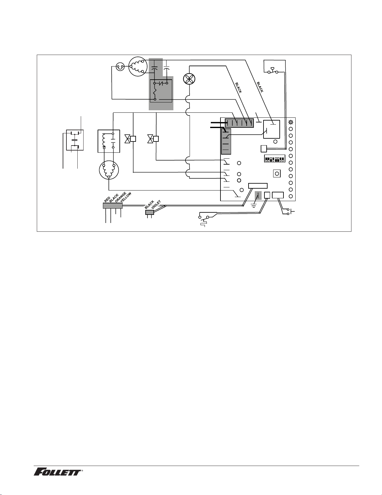
Normal operation – Stage 4
One second (1 s) after the fan comes on, the COMPRESSOR output comes on. The compressor circuit uses both
run and start capacitors along with a potential start relay. The start capacitor in energized through the normally
closed contacts of the start relay.
5
2
1
Start
Run
Compressor
T.O.L.
MAINTENANCE
LOW WATER
TIME DELAY
SLEEP CYCLE
MAKING ICE
LOW BIN
POWER
SERVICE
HI AMPS
HI PRESSURE
DRAIN CLOG
CLEANER FULL
High
Pressure
Switch
R
S
C
Gearmotor
Start
Relay
Start
Relay
N
L1
Fan
A B C D
Water Sensors
RESET
Fill
Valve
Drain
Valve
3
4
2
Bin T-Stat
Clean Switch
Drain Clog Sensor
P6
P21
P20
P19
P3
P22
P4
AUGER
WATER LEVELS
BIN
P11
HI PRS
L1
R
S
C
RED
WHITE
WHITE
BLACK
BROWN
BLUE
RED
BLACK YELLOW
Compressor
Electrical Box
COMPRESSOR
1 2 3 4 5 6 7 8
BLACK
N
P15
Ice Dispense Input
Capacitor
BLACK
YELLOW
OR
NO CONNECT
Normal operation – Stage 5
As the compressor comes up to normal running speed, its start winding generates a voltage potential across the
relay’s coil. This energizes the coil to open the contact and drop out the start capacitor.
The ice machine is now in a normal ice making mode. The ice machine will produce ice until the bin level control
in the ice dispenser is satised.
5
2
1
Start
Run
Compressor
T.O.L.
MAINTENANCE
LOW WATER
TIME DELAY
SLEEP CYCLE
MAKING ICE
LOW BIN
POWER
SERVICE
HI AMPS
HI PRESSURE
DRAIN CLOG
CLEANER FULL
High
Pressure
Switch
R
S
C
Gearmotor
Start
Relay
Start
Relay
N
L1
Fan
A B C D
Water Sensors
RESET
Fill
Valve
Drain
Valve
3
4
2
Bin T-Stat
Clean Switch
Drain Clog Sensor
P6
P21
P20
P19
P3
P22
P4
AUGER
WATER LEVELS
BIN
P11
HI PRS
L1
R
S
C
RED
WHITE
WHITE
BLACK
BROWN
BLUE
RED
BLACK YELLOW
Compressor
Electrical Box
COMPRESSOR
1 2 3 4 5 6 7 8
BLACK
N
P15
Ice Dispense Input
Capacitor
BLACK
YELLOW
OR
NO CONNECT
MCD425A/W, R425A/W, MFD425A/W, P425A/W Ice Machines 17

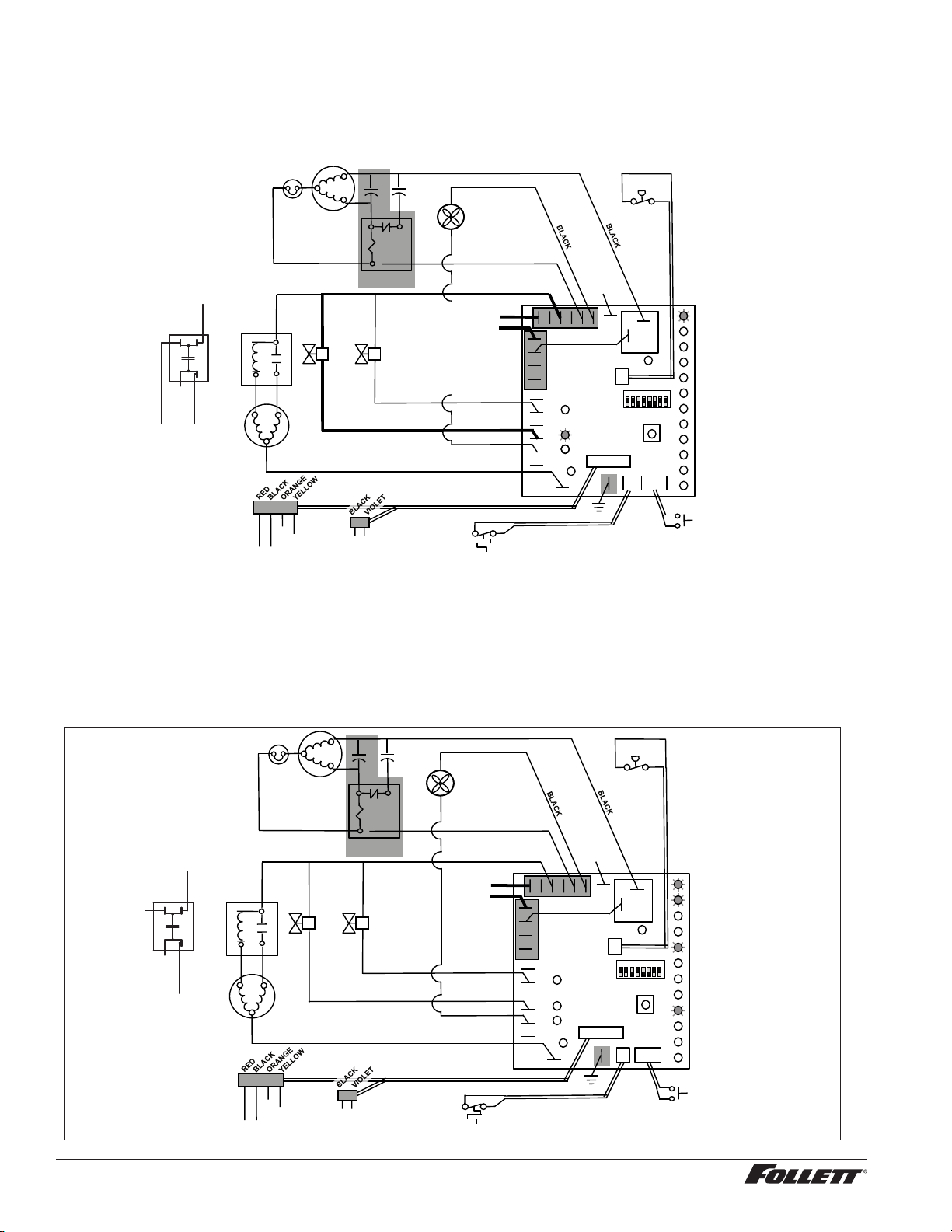
Normal operation – Stage 6
Once the bin thermostat control opens, the LOW BIN LED goes out. The compressor and gear motor outputs turn
off, the MAKING ICE LED goes out and the TIME DELAY LED comes on. .
5
2
1
Start
Run
Compressor
T.O.L.
MAINTENANCE
LOW WATER
TIME DELAY
SLEEP CYCLE
MAKING ICE
LOW BIN
POWER
SERVICE
HI AMPS
HI PRESSURE
DRAIN CLOG
CLEANER FULL
High
Pressure
Switch
R
S
C
Gearmotor
Start
Relay
Start
Relay
N
L1
Fan
A B C D
Water Sensors
RESET
Fill
Valve
Drain
Valve
3
4
2
Bin T-Stat
Clean Switch
Drain Clog Sensor
P6
P21
P20
P19
P3
P22
P4
AUGER
WATER LEVELS
BIN
P11
HI PRS
L1
R
S
C
RED
WHITE
WHITE
BLACK
BROWN
BLUE
RED
BLACK YELLOW
Compressor
Electrical Box
COMPRESSOR
1 2 3 4 5 6 7 8
BLACK
N
P15
Ice Dispense Input
Capacitor
BLACK
YELLOW
OR
NO CONNECT
Normal operation – Stage 7
The fan motor continues for 10 minutes before shutting off. The TIME DELAY LED remains on for 20 minutes.
The ice machine will not start while the TIME DELAY LED is on. To restart the ice machine for troubleshooting
purposes, depress the reset button to clear the control board.
5
2
1
Start
Run
Compressor
T.O.L.
MAINTENANCE
LOW WATER
TIME DELAY
SLEEP CYCLE
MAKING ICE
LOW BIN
POWER
SERVICE
HI AMPS
HI PRESSURE
DRAIN CLOG
CLEANER FULL
High
Pressure
Switch
R
S
C
Gearmotor
Start
Relay
Start
Relay
N
L1
Fan
A B C D
Water Sensors
RESET
Fill
Valve
Drain
Valve
3
4
2
Bin T-Stat
Clean Switch
Drain Clog Sensor
P6
P21
P20
P19
P3
P22
P4
AUGER
WATER LEVELS
BIN
P11
HI PRS
L1
R
S
C
RED
WHITE
WHITE
BLACK
BROWN
BLUE
RED
BLACK YELLOW
Compressor
Electrical Box
COMPRESSOR
1 2 3 4 5 6 7 8
BLACK
N
P15
Ice Dispense Input
Capacitor
BLACK
YELLOW
OR
NO CONNECT
18 MCD425A/W, R425A/W, MFD425A/W, P425A/W Ice Machines
Normal operation – Stage 8
When the dwell time of 20 minutes has expired, the TIME DELAY LED goes off. If 5 seconds of ice has been
dispensed and the SLEEP CYCLE LED (Symphony Plus only) is off, the ice machine will go through the normal
start-up sequence when the bin level control signals the control board for ice.
5
2
1
Start
Run
Compressor
T.O.L.
MAINTENANCE
LOW WATER
TIME DELAY
SLEEP CYCLE
MAKING ICE
LOW BIN
POWER
SERVICE
HI AMPS
HI PRESSURE
DRAIN CLOG
CLEANER FULL
High
Pressure
Switch
R
S
C
Gearmotor
Start
Relay
Start
Relay
N
L1
Fan
A B C D
Water Sensors
RESET
Fill
Valve
Drain
Valve
3
4
2
Bin T-Stat
Clean Switch
Drain Clog Sensor
P6
P21
P20
P19
P3
P22
P4
AUGER
WATER LEVELS
BIN
P11
HI PRS
L1
R
S
C
RED
WHITE
WHITE
BLACK
BROWN
BLUE
RED
BLACK YELLOW
Compressor
Electrical Box
COMPRESSOR
1 2 3 4 5 6 7 8
BLACK
N
P15
Ice Dispense Input
Capacitor
BLACK
YELLOW
OR
NO CONNECT
Quiet Night/Sleep cycle (Symphony Plus only)
The board monitors ice dispensing through a line voltage input to P15. If the ice dispense has not be initiated for
more than 5 seconds during the 20 minute time delay, the SLEEP CYCLE LED comes on. The machine will stay
off for 12 hours unless 5 seconds of dispensing is seen. After 12 hours, the SLEEP CYCLE LED goes out and the
ice making will resume if the bin thermostat is closed. The sleep cycle dispense duration is adjustable using the
DIP switches on the control board.
MCD425A/W, R425A/W, MFD425A/W, P425A/W Ice Machines 19
Self-ushing (when enabled)
At the completion of the 20 minute time delay, the machine checks for a cumulative one hour of ice making time
since the last off-cycle ush. If the cumulative ice making time exceeds one hour, the machine will energize the
drain valve P19 for 60 seconds to drain the evaporator. It will then rell with water, ush again, rell and begin
making ice if the LOW BIN LED is on. If the ice making time is less than 1 hour, the machine will start and begin
making ice without draining the evaporator.
5
2
1
Start
Run
Compressor
T.O.L.
MAINTENANCE
LOW WATER
TIME DELAY
SLEEP CYCLE
MAKING ICE
LOW BIN
POWER
SERVICE
HI AMPS
HI PRESSURE
DRAIN CLOG
CLEANER FULL
High
Pressure
Switch
R
S
C
Gearmotor
Start
Relay
Start
Relay
N
L1
Fan
A B C D
Water Sensors
RESET
Fill
Valve
Drain
Valve
3
4
2
Bin T-Stat
Clean Switch
Drain Clog Sensor
P6
P21
P20
P19
P3
P22
P4
AUGER
WATER LEVELS
BIN
P11
HI PRS
L1
R
S
C
RED
WHITE
WHITE
BLACK
BROWN
BLUE
RED
BLACK YELLOW
Compressor
Electrical Box
COMPRESSOR
1 2 3 4 5 6 7 8
BLACK
N
P15
Ice Dispense Input
Capacitor
BLACK
YELLOW
OR
NO CONNECT
Diagnostic Stages
High gearmotor amps – Stage 1
The HI AMPS error and TIME DELAY LEDs are on indicating that the control board has sensed an over-torque
condition at the P4 terminal (more than 3 amps from the gearmotor) or no current draw (0A) and shut the ice
machine down (strike one). The HI AMPS and TIME DELAY LEDs will remain on for 60 minutes after an over-
torque condition has occurred. The ice machine will remain off as long as these two LEDs are on. After the
60 minute time delay, these LED lights turn off, and the control board will try to go through a normal start-up
sequence.
Capacitor
BLACK
YELLOW
5
2
1
Start
Run
Compressor
T.O.L.
MAINTENANCE
LOW WATER
TIME DELAY
SLEEP CYCLE
MAKING ICE
LOW BIN
POWER
SERVICE
HI AMPS
HI PRESSURE
DRAIN CLOG
CLEANER FULL
High
Pressure
Switch
R
S
C
Gearmotor
Start
Relay
Start
Relay
N
L1
Fan
A B C D
Water Sensors
RESET
Fill
Valve
Drain
Valve
3
4
2
Bin T-Stat
Clean Switch
Drain Clog Sensor
P6
P21
P20
P19
P3
P22
P4
AUGER
WATER LEVELS
BIN
P11
HI PRS
L1
R
S
C
RED
WHITE
WHITE
BLACK
BROWN
BLUE
RED
BLACK YELLOW
Compressor
Electrical Box
COMPRESSOR
1 2 3 4 5 6 7 8
BLACK
N
P15
Ice Dispense Input
OR
NO CONNECT
20 MCD425A/W, R425A/W, MFD425A/W, P425A/W Ice Machines
High gearmotor amps – Stage 2
If the restart is successful the board will continue to monitor the current draw on P4 for 60 minutes looking for
a second high amps (above 3A) occurrence. If the ice machine runs without problems for 60 minutes and no
additional torque errors occur, the ice machine will continue normal operation.
5
2
1
Start
Run
Compressor
T.O.L.
MAINTENANCE
LOW WATER
TIME DELAY
SLEEP CYCLE
MAKING ICE
LOW BIN
POWER
SERVICE
HI AMPS
HI PRESSURE
DRAIN CLOG
CLEANER FULL
High
Pressure
Switch
R
S
C
Gearmotor
Start
Relay
Start
Relay
N
L1
Fan
A B C D
Water Sensors
RESET
Fill
Valve
Drain
Valve
3
4
2
Bin T-Stat
Clean Switch
Drain Clog Sensor
P6
P21
P20
P19
P3
P22
P4
AUGER
WATER LEVELS
BIN
P11
HI PRS
L1
R
S
C
RED
WHITE
WHITE
BLACK
BROWN
BLUE
RED
BLACK YELLOW
Compressor
Electrical Box
COMPRESSOR
1 2 3 4 5 6 7 8
BLACK
N
P15
Ice Dispense Input
Capacitor
BLACK
YELLOW
OR
NO CONNECT
High gearmotor amps – Stage 3
If a second occurrence happens during the 60 minute monitoring period, the HI AMPS LED will come on again
and shut the machine down (strike two). The HI AMPS LED (wihout the TIME DELAY LED) will indicate to the
technician that two consecutive over-torque situations have occurred. The ice machine is shut down at this time
and locked out. It will not restart unless the manual reset button is depressed while power is on.
5
2
1
Start
Run
Compressor
T.O.L.
MAINTENANCE
LOW WATER
TIME DELAY
SLEEP CYCLE
MAKING ICE
LOW BIN
POWER
SERVICE
HI AMPS
HI PRESSURE
DRAIN CLOG
CLEANER FULL
High
Pressure
Switch
R
S
C
Gearmotor
Start
Relay
Start
Relay
N
L1
Fan
A B C D
Water Sensors
RESET
Fill
Valve
Drain
Valve
3
4
2
Bin T-Stat
Clean Switch
Drain Clog Sensor
P6
P21
P20
P19
P3
P22
P4
AUGER
WATER LEVELS
BIN
P11
HI PRS
L1
R
S
C
RED
WHITE
WHITE
BLACK
BROWN
BLUE
RED
BLACK YELLOW
Compressor
Electrical Box
COMPRESSOR
1 2 3 4 5 6 7 8
BLACK
N
P15
Ice Dispense Input
Capacitor
BLACK
YELLOW
OR
NO CONNECT
MCD425A/W, R425A/W, MFD425A/W, P425A/W Ice Machines 21
Loss of water
During operation, the water level cycles between the normal low (D) and normal high (C) water probes - the ll
valve (P21) cycling on and off. If continuity is not detected between the common probe (B) and normal low (D)
within 10 seconds, the LOW WATER and TIME DELAY LEDs will come on and the machine will shut down for
the one hour time delay period. After the time delay, the ll valve will re-energize and wait for continuity between
the common probe and normal high before restarting. LOW WATER LED will remain ON until the water level is
satised.
5
2
1
Start
Run
Compressor
T.O.L.
MAINTENANCE
LOW WATER
TIME DELAY
SLEEP CYCLE
MAKING ICE
LOW BIN
POWER
SERVICE
HI AMPS
HI PRESSURE
DRAIN CLOG
CLEANER FULL
High
Pressure
Switch
R
S
C
Gearmotor
Start
Relay
Start
Relay
N
L1
Fan
A B C D
Water Sensors
RESET
Fill
Valve
Drain
Valve
3
4
2
Bin T-Stat
Clean Switch
Drain Clog Sensor
P6
P21
P20
P19
P3
P22
P4
AUGER
WATER LEVELS
BIN
P11
HI PRS
L1
R
S
C
RED
WHITE
WHITE
BLACK
BROWN
BLUE
RED
BLACK YELLOW
Compressor
Electrical Box
COMPRESSOR
1 2 3 4 5 6 7 8
BLACK
N
P15
Ice Dispense Input
Capacitor
BLACK
YELLOW
OR
NO CONNECT
22 MCD425A/W, R425A/W, MFD425A/W, P425A/W Ice Machines
High refrigerant pressure
Should the refrigeration pressure rise above 425 psi, the high pressure switch contacts will open. The board sees
the open circuit and the HIGH PRESSURE and TIME DELAY LEDs will come on, the machine shuts down. After
the one hour time delay, the machine will attempt to restart. If the pressure has fallen below the reset point of 295
psi and the board see the contacts closed, the machine will resume normal operation. If the contacts are still open
after the restart, the board will again go into HIGH PRESSURE and TIME DELAY, cycling until contact closure is
seen.
5
2
1
Start
Run
Compressor
T.O.L.
MAINTENANCE
LOW WATER
TIME DELAY
SLEEP CYCLE
MAKING ICE
LOW BIN
POWER
SERVICE
HI AMPS
HI PRESSURE
DRAIN CLOG
CLEANER FULL
High
Pressure
Switch
R
S
C
Gearmotor
Start
Relay
Start
Relay
N
L1
Fan
A B C D
Water Sensors
RESET
Fill
Valve
Drain
Valve
3
4
2
Bin T-Stat
Clean Switch
Drain Clog Sensor
P6
P21
P20
P19
P3
P22
P4
AUGER
WATER LEVELS
BIN
P11
HI PRS
L1
R
S
C
RED
WHITE
WHITE
BLACK
BROWN
BLUE
RED
BLACK YELLOW
Compressor
Electrical Box
COMPRESSOR
1 2 3 4 5 6 7 8
BLACK
N
P15
Ice Dispense Input
Capacitor
BLACK
YELLOW
OR
NO CONNECT
Drain clog
If continuity is seen between the two drain clog sensor probes, the DRAIN CLOG LED will come on and the
machine will shut down. The machine will not restart unless the manual reset button is depressed while power is
on.
5
2
1
Start
Run
Compressor
T.O.L.
MAINTENANCE
LOW WATER
TIME DELAY
SLEEP CYCLE
MAKING ICE
LOW BIN
POWER
SERVICE
HI AMPS
HI PRESSURE
DRAIN CLOG
CLEANER FULL
High
Pressure
Switch
R
S
C
Gearmotor
Start
Relay
Start
Relay
N
L1
Fan
A B C D
Water Sensors
RESET
Fill
Valve
Drain
Valve
3
4
2
Bin T-Stat
Clean Switch
Drain Clog Sensor
P6
P21
P20
P19
P3
P22
P4
AUGER
WATER LEVELS
BIN
P11
HI PRS
L1
R
S
C
RED
WHITE
WHITE
BLACK
BROWN
BLUE
RED
BLACK YELLOW
Compressor
Electrical Box
COMPRESSOR
1 2 3 4 5 6 7 8
BLACK
N
P15
Ice Dispense Input
Capacitor
BLACK
YELLOW
OR
NO CONNECT
MCD425A/W, R425A/W, MFD425A/W, P425A/W Ice Machines 23
Refrigeration system (all models)
All service on refrigeration systems must be performed in accordance with all federal, state and local laws. It is the
responsibility of the technician to ensure that these requirements are met. Recharging ice machine to other than
factory specications will void the warranty.
R404A ice machine charge specications
Model Charge Refrigerant type
MCD425A, MFD425A, R425A, P425A (air-cooled) 15 oz. (425 g) R404A
MCD425W, MFD425W, R425W, P425W (water-cooled) 9 oz. (255 g) R404A
Refrigerant replacement requirements
1. Non-contaminated refrigerant removed from any Follett refrigeration system can be recycled and returned
to the same system after completing repairs. Recycled refrigerant must be stored in a clean, approved
storage container. If additional refrigerant is required, virgin or reclaimed refrigerant that meets ARI
standard 700-88 must be used.
2. In the event of system contamination (for example, a compressor burn out, refrigerant leak, presence of
non-condensibles or moisture), the system must be repaired, evacuated and recharged using virgin or
reclaimed refrigerant that meets ARI standard 700-88.
3. Follett Corporation does not approve of recovered refrigerants. Improper refrigeration servicing
procedures will void the factory warranty.
Evacuation
Evacuate the system to a level of 500 microns. When the 500 micron level is reached, close valves and both
manifold and shut down the vacuum pump. Allow the system to sit for approximately 20 minutes. During this period
the system pressure should not rise. If the system pressure rises and stabilizes there is moisture in the system and
further evacuation is needed. If the pressure continues to rise check the system for leaks.
Ice capacity test
Ice machine production capacity can only be determined by weighing ice produced in a specic time period.
Replace all panels on ice machine.
1. Run ice machine for at least 15 minutes.
2. Weigh and record weight of container used to catch ice.
3. Catch ice for 15 or 20 minutes.
4. Weigh harvested ice and record total weight.
5. Subtract weight of container from total weight.
6. Convert fractions of pounds to decimal equivalents (ex. 6 lb 8 oz. = 6.5 lb).
7. Calculate production using following formula:
1440 min. x wt. of ice produced
= Production capacity/24 hr. period
Total test time in minutes
8. Calculated amount per 24 hours should be checked against rated capacity for same ambient and water
temperatures in Ice Production Tables.
24 MCD425A/W, R425A/W, MFD425A/W, P425A/W Ice Machines
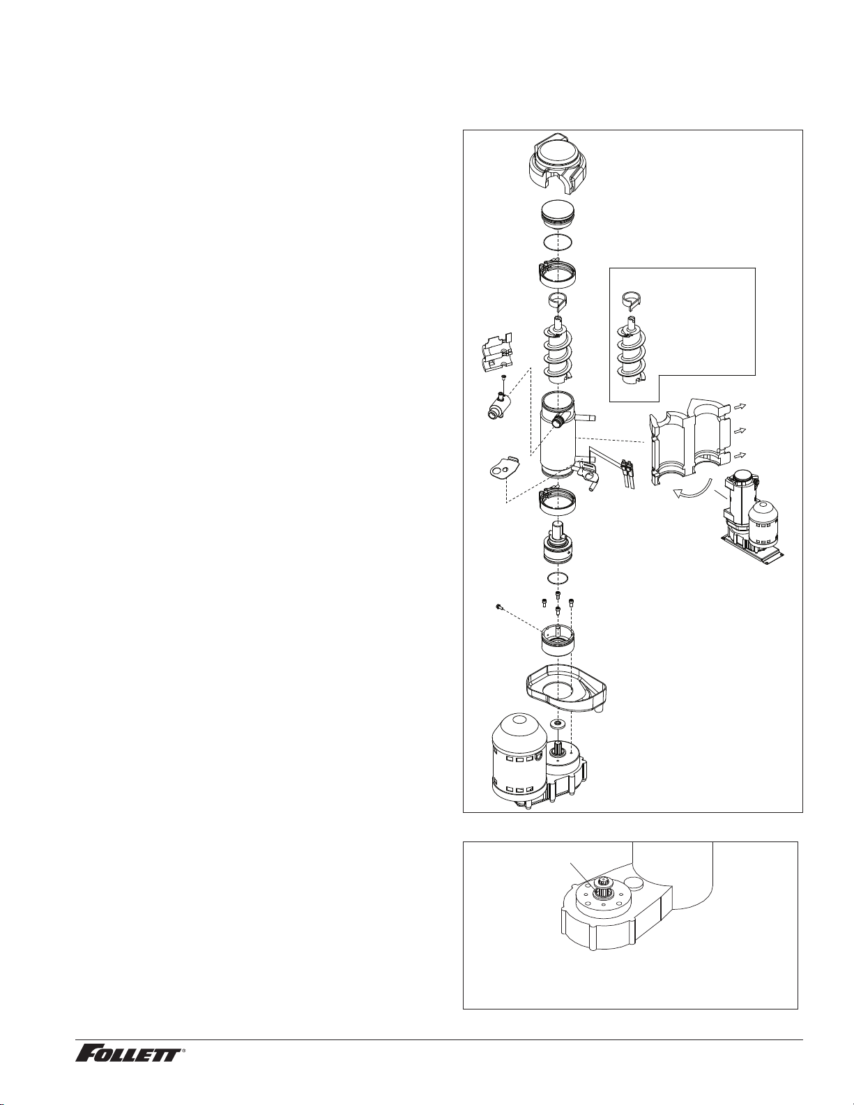
Evaporator disassembly
Note: The upper bearing, lower bearing and auger assemblies must be replaced as assemblies. The bottom and
top bearing assemblies cannot be eld assembled to factory specications.
1. Press CLEAN switch.
2. Wait for LOW WATER light to illuminate.
3. Turn OFF power.
4. Remove top bearing insulation and
compression nozzle insulation.
5. Disconnect vent and drain tube from nozzle.
6. Disconnect compression nozzle from
evaporator.
7. Disconnect evaporator water feed line.
8. Remove nut and upper v-band coupling from
top of evaporator.
9. Lift top bearing assembly straight up with a
slight rotating motion and remove.
10. Remove ice compression loop located at top of
auger.
11. Lift auger straight up and out of evaporator.
12. Remove nut and lower vee band coupling from
bottom of evaporator.
13. Lift evaporator to clear bottom bearing
assembly.
14. Loosen hex head bolt in side of mounting
base with 5/16 wrench and lift lower bearing
assembly.
15. Remove condensate shield.
16. Remove 4 Allen head machine screws holding
mounting base to gearbox.
Fig. 3
AUGER 00124123
COMPRESSION
FLAKER COMPONENTS
LOOP 00124115
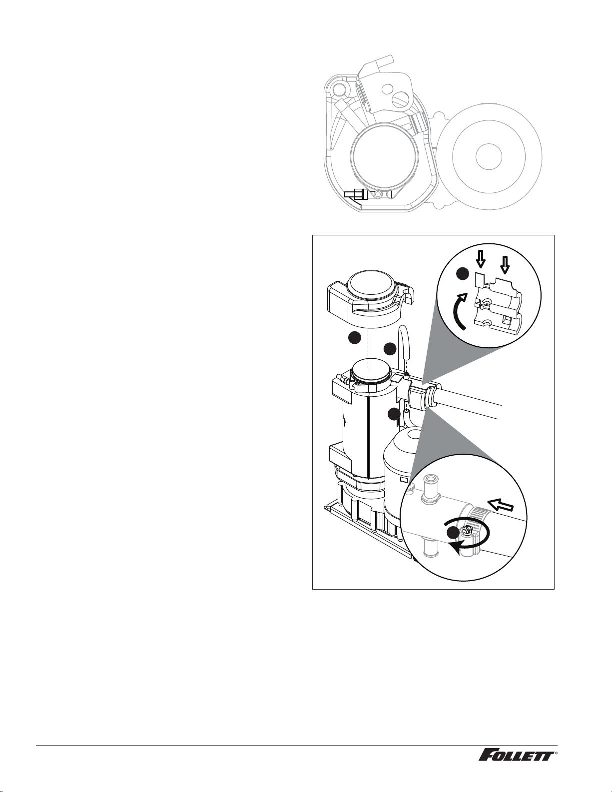
Evaporator reassembly
1. Clean gearmotor boss, output shaft and shaft
well.
2. Install drain pan and evaporator mounting
base.
3. Fill gear motor shaft well with food grade
grease (Fig. 4).
4. Install condensate shield and seat against
gear motor boss.
5. Install bearing O ring in groove in evaporator
mounting base.
Fig. 4
Apply grease in well
Evaporator drain pan and mounting base not shown for clarity.
MCD425A/W, R425A/W, MFD425A/W, P425A/W Ice Machines 25
26 MCD425A/W, R425A/W, MFD425A/W, P425A/W Ice Machines
6. Lower bottom bearing assembly into
evaporator mounting base.
7. While maintaining rm downward pressure
on bottom bearing assembly, tighten hex
head bolt with a 5/16 wrench.
8. Position evaporator over lower bearing
assembly and align grooves with pins in
bearing assembly.
9. Install vee band clamp and nut to 70 in/lb.
(Fig. 5).
Note: Clamp must be oriented as shown
in order for the insulation to be placed
properly.
10. Place auger in center of evaporator and
rotate to mate with drive pin.
11. Install ice compression loop, orienting loop.
12. Install upper bearing and seal assembly,
rotating bearing to slip pin into auger slot.
13. Install upper vee band clamp and nut to
70in/lb.
14. Install evaporator insulation.
15. Install compression nozzle and tubing.
16. Secure ice transport tube with clamp
(Fig.6.1).
Note: Clamp must be oriented as shown
in order for the insulation to be placed
properly.
1 7. Install compression nozzle insulation
(Fig.6.2).
18. Install vent and drain tube (Fig.6.3).
19. Install top bearing insulation (Fig.6.4).
Gearmotor replacement
1. Disassemble evaporator.
2. Disconnect the wire connectors.
3. Remove 4 screws holding gear motor
mounting plate to base of ice machine and
lift gearbox and motor clear of ice machine.
4. Remove machine screws holding mounting
plate to motor.
5. Install new motor in reverse order.
Fig. 5
Fig. 6
4
3
3
1
2
MCD425A/W, R425A/W, MFD425A/W, P425A/W Ice Machines 27
Replacement parts
Replacement ice machine ordering matrix
Dispenser models Replacement ice machine model
Dispensers with top mounted ice machines
50CT425A & 50HT425A P425A
50HT425W & 50HT425W P425W
25CT 425A & 25HT425A P425A
25CT425W & 25HT425W P425W
110CT425A P425A
110CT425W P425W
Dispensers with remote ice machines
25CR425A & 25HR425A R425A
25CR425W & 25HR425W R425W
50CR425A & 50HR425A R425A
50CR425W & 50HR425W R425W
110CR425A R425A
110CR425W R425W
All U150/VU155 series with air-cooled ice machines MCD425AVS
All U150/VU155 series with water-cooled ice machines MCD425W
All VU300 series with air-cooled ice machines MCD425A
All VU300 series with water-cooled ice machines MCD425W
Freestanding dispensers with ice machines in the base
25FB425A P425A
25FB425W P425W
50FB425A P425A
50FB425W P425W
110FB425A P425A
110FB425W P425W
Nugget ice machine on top of bin
MCD425ABT MCD425ABT*
MCD425WBT MCD425WBT*
Flake ice machine on top of bin
MFD425ABT MFD425ABT*
MFD425WBT MFD425WBT*
* New bin top required.
Ice machine cleaner/descaler
00132001 SafeCLEAN environmentally-friendly cleaner, carton of 24 x 7 oz packets
Ice machine sanitizer
00979674 Nu-Calgon IMS-II or IMS-III Sanitizer, 16 oz. bottle
00131524 Sponge, sanitary, each
Miscellaneous
Part # Description
501860 Condensate pump
502775 Oil, gearmotor, 1 pint
501111 Grease, Mobile FM 222, 14 oz tube
500377 Clamp, ice tube
501425 Grille
01075431 Sponge, sanitary, pack of 24
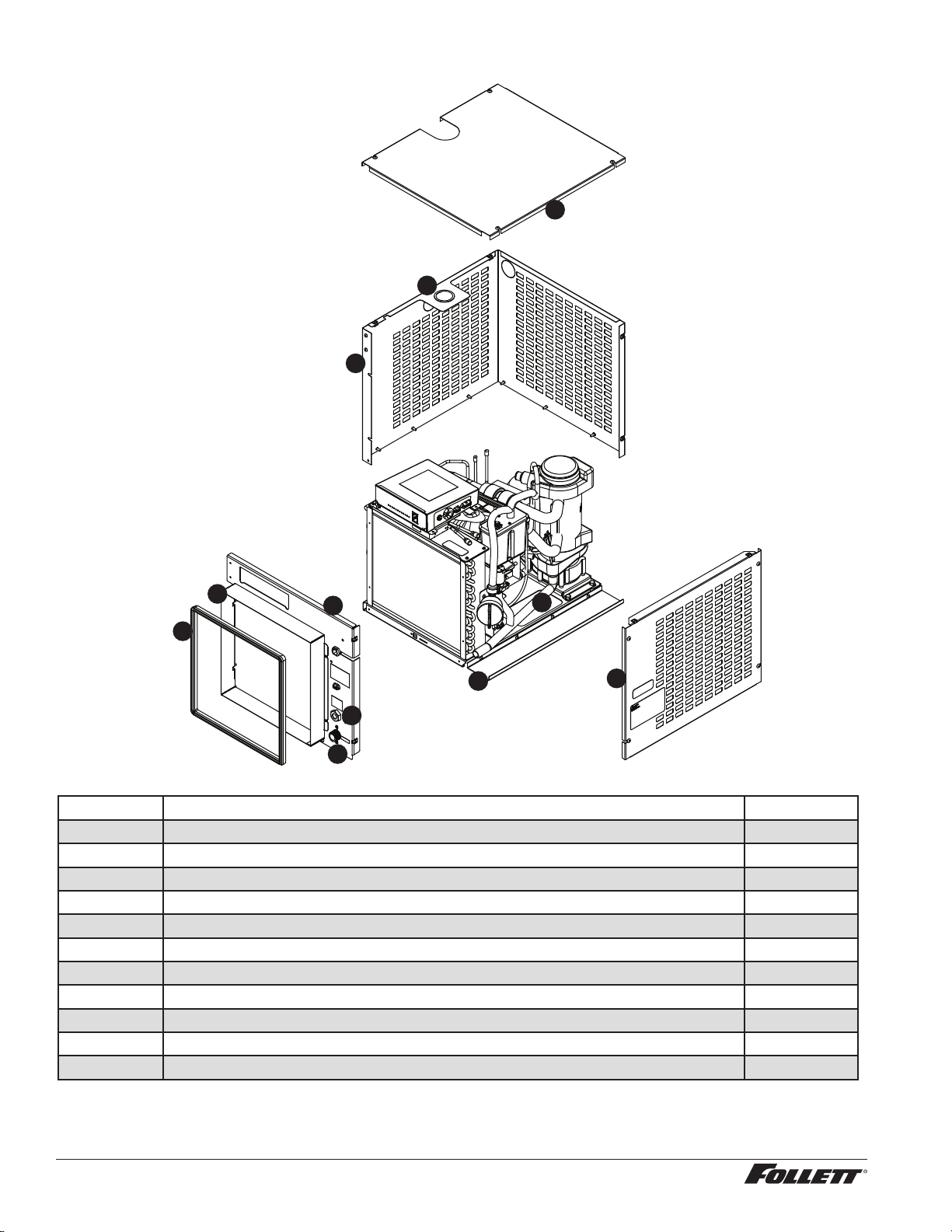
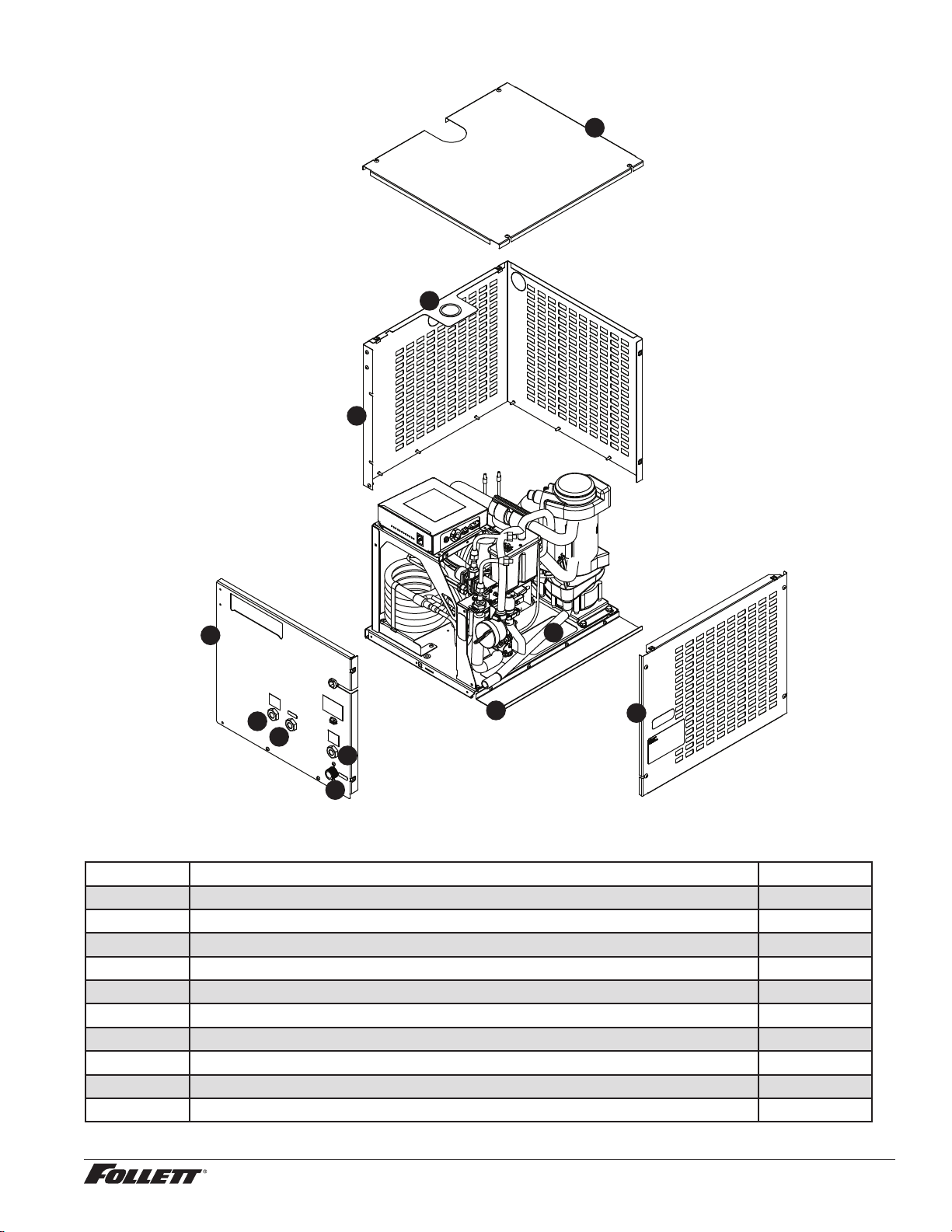
Air-cooled skins assembly (MCD425A_S, R425A)
7
10
9
8
6
5
1
11
3
2
4
Reference # Description Part #
1 Gasket, duct 502781
2 Duct (including gasket) 01068188
3 Front panel 01068204
4 Spacer, base 01068220
5 Panel, right side 01068238
6 Panel, left side and rear (1 piece) 01068246
7 Bushing 01026152
8 Panel, top 01068253
9 Tube, drain 01016948
10 Fitting, water 01065375
11 Fitting, drain 00109728
28 MCD425A/W, R425A/W, MFD425A/W, P425A/W Ice Machines
Water-cooled skins assembly (MCD425W_S, R425W)
7
10
9
8
6
5
1
1
3
2
4
Reference # Description Part #
1 Fitting, condenser 00195966
2 Fitting, water 01065375
3 Fitting, drain 00109728
4 Panel, front 01068261
5 Spacer, base 01068220
6 Panel, right side 01068238
7 Tube, drain 01016948
8 Panel, left side and rear (1 piece) 01068246
9 Bushing 01026152
10 Panel, top 01068253
MCD425A/W, R425A/W, MFD425A/W, P425A/W Ice Machines 29
30 MCD425A/W, R425A/W, MFD425A/W, P425A/W Ice Machines
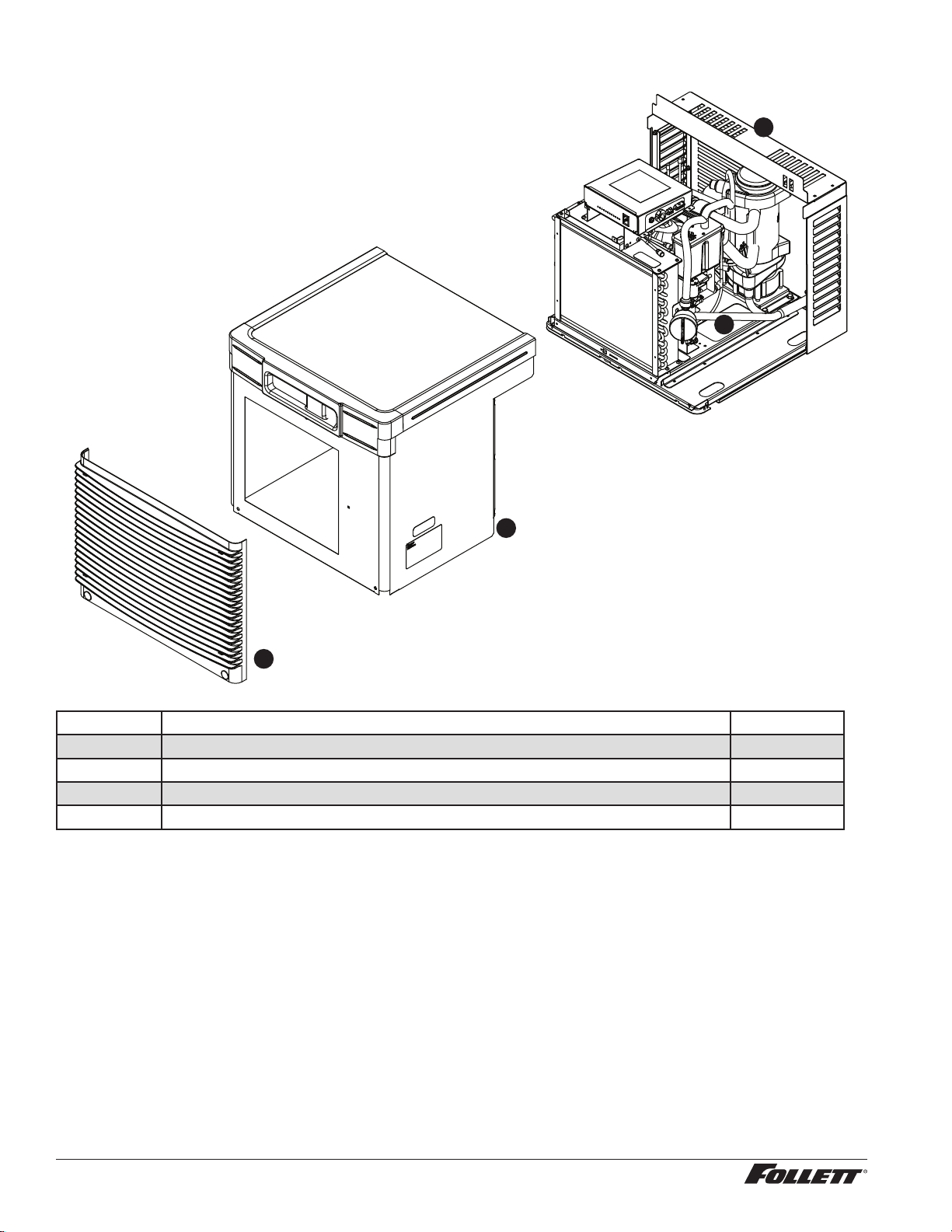
Louvered docking station (MCD425A/W_T)
1
2
3
4
Reference # Description Part #
1 Louver, front 01006154
2 Cover, front 01068279
3 Tube, drain 01055185
4 Lovered docking station 01068287
MCD425A/W, R425A/W, MFD425A/W, P425A/W Ice Machines 31
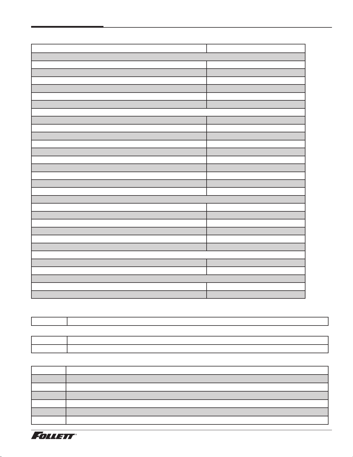
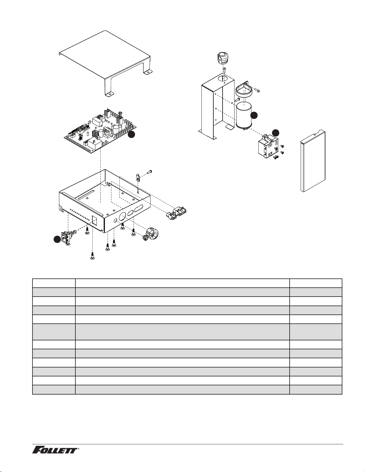
Electrical components
4
3
2
1
Reference # Description Part #
1 Capacitor, run 00997759
2 Relay start, compressor, 115 V, 60 Hz 00997726
3 Board, control circuit, 115 V, 60 Hz 01064708
4 Switch, clean 00117036
Not shown Bin thermostat (MCD425A/WBT, MCD425A/WHT, MFD425A/WBT and
MFD425A/WHT only)
500514
Not shown Board, stand off control (8 required) 00903005
Not shown Relay, power to contact closure 01020734
Not shown Jumper, bin signal 01069095
Not shown Cord and plug, power 01075589
Not shown Converter, bin signal, Vision 01067156
Not shown Relay, bin signal (power to contact closure) 01020734
32 MCD425A/W, R425A/W, MFD425A/W, P425A/W Ice Machines
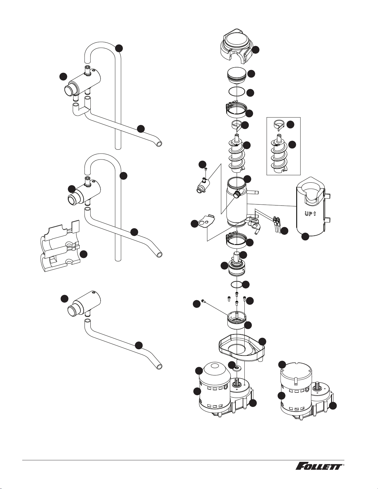
Evaporator
FOOD SERVICE
HEALTHCARE
FLAKER
FLAKER
COMPONENTS
27
15
17
25
1
3
4
5
20
19
7
6
8
10
11
12
16
9
22
21
1
17
18
18
26
24
2
28
23
32
3
4
29
13
13
30
31
MCD425A/W, R425A/W, MFD425A/W, P425A/W Ice Machines 33
Evaporator
Reference # Description Part #
1 Coupling, vee band, includes nut 502735
2 Bearing assembly, top 502736
3 Loop, ice compression, beveled (see below for Flaker-specic components) 502110
4 Auger (see below for Flaker-specic components) 502737
5 Evaporator (includes insulation jacket, 502740) 01064658
6 O ring, bearing housing 500496
7 Bearing assembly, bottom (includes O rings and condensate shield) 502738
8 O ring, mounting base 501063
9 Shield, condensate 500744
10 Screw, Allen 1/4 20 x 1/2 (set of 4) 501080
11 Mounting base, evap. (includes 501063) 502733
12 Bolt, mounting base 502227
13 Gearbox and motor 502730
Not shown Mounting base, gearbox 01067693
15 Compression nozzle, with single drain 01064674
16 Drain pan, evaporator 00181990
17 Tube, compression nozzle vent 01027804
18 Tube, compression nozzle, single drain 01027416
Not shown Grease, Chevron SRI-2, 14 oz 501111
19 Bracket, vent hoses 01007087
20 Insulation jacket, evaporator 01049592
21 Relay, gearmotor (for split-phase motor only) 00142042
22 Cover, black plastic 01012228
23 Nozzle, compression, dual drain 01067446
24 O ring, top bearing 01064963
25 Tube, compression nozzle, dual drain 01033778
26 Sensor, overow 01039783
27 Insulation, top bearing 01049600
28 Insulation, compression nozzle, single drain 01049584
29 16 µF Capacitor (for PSC motor only) 01103142
30 Screw, compression nozzle 00956250
31 Cover, aluminum 01106376
Not shown O-ring, compression nozzle 00988097
Flaker-specic components
Reference # Description Part #
3 Loop, compression, notched 00124115
4 Auger (with paddle) 00124123
18 Tube, compression nozzle, single drain 01027416
32 Compression nozzle, aker 01067453

34 MCD425A/W, R425A/W, MFD425A/W, P425A/W Ice Machines
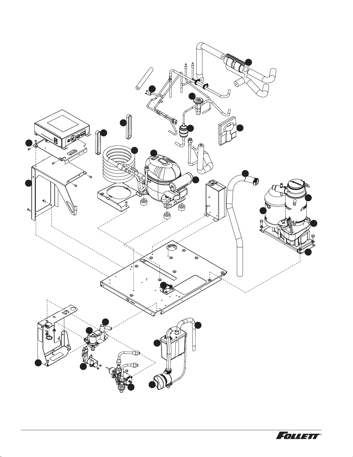
Air-cooled ice machines
2
15
21
3
12
20
7
6
10
22
17
16
9
13
1
14
8
18
19
5
4
11
23
24
25
MCD425A/W, R425A/W, MFD425A/W, P425A/W Ice Machines 35
Air-cooled ice machines
Reference # Description Part #
1 Drier 502724
2 Condenser coil, A/C 01067461
3 Reservoir mounting bracket, a/c 01072909
4 Reservoir assembly 01064682
5 Bracket, electrical box 01068170
6 Evaporator (see page 32 and 33 for complete breakdown) —
Not shown Tubing, polypropylene, reservoir supply (sold by foot) 502079
7 Valve, expansion, thermal 502726
8 Drain pan, evaporator 0018190
9 High pressure cutout 00117077
10 Mounting bracket, gearbox 01067693
11 Gearbox & motor assembly, 115 V, 60 Hz 502730
12 Tubing, clean and vent 00998765
13 Fan blade 500474
14 Motor, fan, 115 V, 60 Hz 500672
15 Bracket, fan motor 01067107
Not shown Overload, compressor, 115 V, 60 Hz 01027572
16 Compressor, 115 V, 60 Hz 01065259
17 Tube, ll/purge - reservoir-solenoid-evaporator feed 01051192
Not shown Water inlet tting, brass 01065275
Not shown Fitting, reservoir, plastic 1/4" stem x 1/4" push-in 00121699
18 Jacket, insulation, TXV 502830
19 Bracket, ice tube entry 01067644
20 Solenoid, purge 01146257
21 Solenoid, ll 01082403
Not shown Tube, drain, MCD425AxT, 25/50FB 01055185
Not shown Tube, drain, MCD425AxT, 110FB, 110CT 01055540
Not shown Tube, drain, MCD425AxS 01016948
22 Tube, ice transport, MCD425A/WxT 01003532
23 Jacket, insulation, TXV bulb 00106534
24 Cup, cleaning 01065226
Not shown Gasket, reservoir 00990978
25 Capacitor, start 01026145
36 MCD425A/W, R425A/W, MFD425A/W, P425A/W Ice Machines
Water-cooled ice machines
14
18
2
3
17
19
20
4
10
8
5
9
21
12
13
6
11
16
16
15
7
1
22
24
23
25

MCD425A/W, R425A/W, MFD425A/W, P425A/W Ice Machines 37
Water-cooled ice machines
Reference # Description Part #
1 Drier 502724
2 Valve, water regulating (includes Iso-washer) 500537
Not shown Iso-washer (for water regulating valve) 501810
3 Reservoir assembly 01064682
4 Reservoir mounting bracket 01068162
Not shown Tubing, polypropylene, reservoir supply (sold by foot) 502079
Not shown Fitting, reservoir, plastic 1/4" stem x 1/4" push-in 00121699
5 Evaporator (see page 32 and 33 for complete breakdown) —
6 Bracket, electrical box tower 01068121
7 Valve, expansion, thermal 502726
8 Drain pan, evaporator 00181990
9 Gearbox & motor assembly, 115 V, 60 Hz 502730
10 Mounting bracket, gearbox 01067693
11 Bracket, electrical box mounting 01068139
Not shown Overload compressor, 115 V, 60 Hz 01027572
12 Compressor, 115 V, 60 Hz 01065259
13 Coil, condenser 00195933
14 Tube, clean and vent 00998765
Not shown Water inlet tting, brass 01065275
15 High pressure cutout 00117077
16 Ty-rap (2 required) 204584
17 Tube, ll/purge - reservoir-solenoid-evaporator feed 01051192
18 Bracket, ice tube entry 01067644
19 Solenoid, purge 01146257
20 Solenoid, ll 01082403
Not shown Tube, drain, 25/50CI 01054576
Not shown Tube, drain, MCD425AxT, 25/50FB 01055185
Not shown Tube, drain, MCD425AxT, 110FB, 110CT 01055540
Not shown Tube, drain, MCD425AxS 01016948
21 Tube, ice transport, MCD425A/WxT 01003532
22 Jacket, insulation, TXV 502830
23 Jacket, insulation, TXV bulb 00106534
24 Cup, cleaning 01065226
Not shown Bracket, ll solenoid 01072867
Not shown Gasket, reservoir 00990978
25 Capacitor, start 01026145
38 MCD425A/W, R425A/W, MFD425A/W, P425A/W Ice Machines
Water treatment accessories for Symphony ice and water dispensers
Reference # Description Part #
Standard capacity lter system
Not shown Follett QC4-FL4S water lter system (includes FL4S primary cartridge and head, coarse
pre-lter and head, pressure gauge, ushing valve; assembled and installed on mounting
bracket), one per ice machine
00130229
Not shown Follett FL4S primary replacement cartridge 00130245
Not shown Water lter cartridge – primary, carton of 6 00954297
Not shown Everpure coarse pre-lter cartridge 00130211
Not shown Water pre-lter cartridge – pre-lter, carton of 12 00954305
High capacity lter system
Not shown High capacity water lter system (one per ice machine) 00978957
Not shown High capacity water lter cartridge – primary, single 00978965
Not shown High capacity water lter cartridge – primary, carton of 6 00978973
Not shown Water pre-lter cartridge – pre-lter, single 00130211
Not shown Water pre-lter cartridge – pre-lter, carton of 12 00954305
Carbonless high capacity lter system
Not shown Carbonless high capacity water lter system (one per ice machine) – Horizon™ and Mae-
stroPlus series ice machines
01050442
Not shown Carbonless high capacity water lter cartridge – primary, single 01050426
Not shown Carbonless high capacity water lter cartridge – primary, carton of 6 01050434
Not shown Water pre-lter cartridge – pre-lter, single 00130211
Not shown Water pre-lter cartridge – pre-lter, carton of 12 00954305
Other ltration
Not shown Claris hardness removal ltration system 00986059
Not shown Replacement lter for Claris system 00985127
Not shown Reverse osmosis system, 200 gallons per day 00986034
Not shown Replacement reverse osmosis cartridge 00985085
Not shown Replacement reverse osmosis pre-lter 00985077
Not shown Cleaning plug for reverse osmosis system 00985119
Not shown Cleaning cartridge for reverse osmosis system 00985101
Water pressure
Not shown Water pressure regulator (25 psi) 501781
Miscellaneous
Reference # Description Part #
Not shown Diverter plate (single agitator Cornelius dispensers and left-hand
dispense chute on dual-agitator Cornelius dispensers)
307277
Not shown Diverter plate (right-hand dispense chute on dual-agitator dispensers) 00996207
Not shown Diverter plate, Cornelius Flavor Fusion 01100825

MCD425A/W, R425A/W, MFD425A/W, P425A/W Ice Machines 39

40 MCD425A/W, R425A/W, MFD425A/W, P425A/W Ice Machines

MCD425A/W, R425A/W, MFD425A/W, P425A/W Ice Machines 41

42 MCD425A/W, R425A/W, MFD425A/W, P425A/W Ice Machines
Rejestracja gwarancji i ocena sprzętu
Dziękujemy za zakup urządzenia firmy Follett. Mamy nadzieję, że nasze urządzenia spełniają i przekraczają Państwa oczekiwania, gdyż
naszym celem jest dostarczenie klientom wysoce wartościowych produktów i usług, zasługujących na ich pełne uznanie.
Prosimy zapoznać się z załączoną instrukcją instalacji i obsługi. Istotne jest przeprowadzenie instalacji zgodnie z wymogami producenta, co
zapewni działanie urządzenia z maksymalną wydajnością.
Follett LLC nie będzie ponosić odpowiedzialności za szkody wtórne, wydatki, koszty podłączania lub odłączania lub jakiekolwiek straty
wynikające z wady urządzenia.
Aby uzyskać szczegółowe informacje na temat warunków gwarancji, prosimy odwiedzić naszą strone internetową www.follettice.com/
productwarranties.
Rejestracja gwarancji i ocena urządzenia to istotne czynności, ułatwiające nam utrzymanie aktualnych danych o miejscach instalacji naszych
urządzeń i o ich działaniu. Prosimy o zarejestrowanie gwarancji na nabyte urządzenie firmy Follett na naszej witrynie www.follettice.com/
support, gdzie należy wybrać Warranty Registration (Rejestracja gwarancji) i Equipment Evaluation (Ocena urządzenia). Jest to łatwe
i nieskomplikowane, prosimy o znalezienie na to paru minut jeszcze dzisiaj. Na formularzu jest również miejsce na przekazanie nam
komentarzy i informacji zwrotnych. Proszę podzielić się z nami swoimi wrażeniami, abyśmy mogli wykorzystać je w naszych ciągłych
dążeniach do usprawnień.
Jesteśmy dumni z naszych znakomitych urządzeń i staramy się usilnie wspierać je znakomitą obsługą klienta i wsparciem technicznym.
Chcielibyśmy wiedzieć, w jaki jeszcze sposób moglibyśmy Państwu pomóc. Z przyjemnością odpowiemy na Państwa pytania.
Registro de Garantía y Evaluación del Equipo
Gracias por haber elegido este producto Follett ®. Esperamos que nuestro equipo cumpla o supere sus expectativas porque es nuestro objetivo
ofrecer productos y servicios de gran valor que se ganen su plena confianza.
Le rogamos consulte el manual de instalación y de instrucciones adjunto, ya que es muy importante que la instalación se realice según las
especificaciones de fábrica para que el equipo funcione a su máxima eficiencia.
Follett LLC no se hace responsable de los daños indirectos, costos, gastos por conexión y desconexión o pérdidas por causa de defecto de la
máquina.
Si desea una información más completa sobre la garantía, visite nuestro sitio web www.follettice.com/productwarranties.
Las operaciones de registro de la garantía y evaluación del equipo son importantes para que podamos realizar un seguimiento de nuestro
equipo y registrar el rendimiento de la maquinaria. Por favor, registre las garantías del equipo Follett en nuestro sitio web www.follettice.
com/support y seleccione Registro de la Garantía y Evaluación del Equipo. Es muy sencillo, solo le llevará un momento realizar hoy mismo
el registro. En el formulario incluimos un espacio en blanco para sus comentarios y opiniones. Infórmenos sobre su experiencia para que
podamos incorporarla a nuestros continuos esfuerzos de mejora.
Nos enorgullecemos de producir un equipo excepcional y trabajamos duro para respaldarlo con un soporte técnico y un servicio de atención
al cliente de primera. Le rogamos nos indique qué más podemos hacer para ayudarle. Estaremos encantados de responder a sus dudas.
Enregistrement de la garantie et évaluation de l’équipement
Merci d’avoir acheté un équipement Follett®. Notre objectif étant d’offrir des produits et des services de grande valeur vous satisfaisant
pleinement, nous espérons que celui-ci satisfera, voire dépassera, vos attentes !
Veuillez consulter le manuel d’installation et d’exploitation. Il est important que l’installation soit réalisée conformément aux spécifications
de l’usine, de sorte que votre équipement fonctionne à son rendement maximum.
Follett LLC n’est pas responsable de tout dommage consécutif, de toute dépense, de tout frais de raccordement ou de déconnexion, ni de
toute perte liée à un défaut de la machine.
Pour lire la garantie dans son ensemble, visitez notre site Internet www.follettice.com/productwarranties.
L’enregistrement de la garantie et l’évaluation de l’équipement sont importants pour nous aider à suivre notre équipement et pour enregistrer
les performances de la machine. Nous vous demandons donc d’enregistrer la garantie de votre équipement Follett sur notre site Internet,
www.follettice.com/support, dans la section Warranty Registration and Equipment Evaluation. Cette opération est simple ; veuillez prendre
un moment pour la réaliser aujourd’hui.
Le formulaire contient également un espace pour nous faire parvenir vos commentaires et un retour d’informations. Veuillez nous faire part
de votre expérience pour que nous puissions prendre appui dessus pour poursuivre nos efforts constants d’amélioration.
Nous sommes fiers de produire des équipements exceptionnels et nous travaillons avec acharnement pour y associer une assistance à la
clientèle et technique exceptionnelle. N’hésitez pas à nous indiquer dans quelle mesure nous pouvons vous aider. Nous serions ravis de
répondre à vos questions.
Garantieregistrierung und Produktbeurteilung
Vielen Dank, dass Sie sich für ein Follett®-Produkt entschieden haben. Wir hoffen, dass unser Produkt Ihre Erwartungen erfüllen oder
sogar übertreffen wird, weil wir uns zum Ziel gesetzt haben, hochwertige Produkte und Leistungen anzubieten, die Ihre uneingeschränkte
Anerkennung verdienen werden!
Lesen Sie sich bitte die beiliegende Installations- und Betriebsanleitung durch. Es ist wichtig, dass die Installation entsprechend den
Werksangaben erfolgt, damit Ihr Produkt mit maximalem Wirkungsgrad arbeiten kann.
Follett LLC ist nicht für Folgeschäden, Ausgaben, Gebühren für Anschluss oder Abschaltung oder Verluste aufgrund eines Defekts der
Maschine haftbar.
Vollständige Garantieinformationen finden Sie auf unserer Website unter www.follettice.com/productwarranties.

MCD425A/W, R425A/W, MFD425A/W, P425A/W Ice Machines 43
Garantieregistrierung und Produktbeurteilung sind wichtig, damit wir einen Überblick über unsere Produkte behalten und ihre Effizienz
bewerten können. Wir möchten Sie bitten, Garantien für Follett-Produkte auf unserer Website www.follettice.com/support zu registrieren und
den Punkt „Garantieregistrierung und Produktbeurteilung” zu wählen. Es ist ganz einfach. Nehmen Sie sich bitte einen Moment Zeit, um
die Registrierung heute vorzunehmen. Auf dem Formular ist auch Platz für Kommentare und Feedback vorhanden. Teilen Sie uns bitte Ihre
Erfahrungen mit unseren Produkten mit, damit wir sie für unsere fortlaufenden Produktverbesserungen verwenden können.
Wir sind stolz darauf, dass wir besondere Produkte herstellen, und wir bemühen uns, unsere Produkte mit besonderem Kundendienst zu
unterstützen. Lassen Sie uns bitte wissen, was wir noch für Sie tun können. Wir werden Ihre Fragen gerne beantworten.
Registrazione della garanzia e valutazione dell’attrezzatura
Grazie per aver acquistato un dispositivo Follett®. Ci auguriamo che il nostro prodotto soddisfi o superi le Sue aspettative, in quanto il
nostro obiettivo è quello di offrire prodotti e servizi di alta qualità che soddisfino pienamente le vostre esigenze!
La preghiamo di leggere attentamente il manuale per l’installazione e per l’uso allegato. È infatti importante che l’installazione sia effettuata
secondo le specifiche di fabbrica in modo tale che il dispositivo operi con la massima efficienza.
La Follett LLC non si assume alcuna responsabilità per danni conseguenti, spese, costi di collegamento o scollegamento o eventuali perdite
dovute ad un difetto della macchina.
Per visualizzare i dettagli completi relativi alla garanzia, recarsi alla pagina www.follettice.com/productwarranties.
La registrazione della garanzia e la valutazione dell’attrezzatura sono importanti per aiutarci a tenere traccia dei nostri dispositivi e a
registrare le prestazioni della macchina. Le chiediamo dunque di registrare le garanzie relative al dispositivo Follett sul nostro sito Web alla
pagina www.follettice.com/support scegliendo Registrazione della garanzia e Valutazione dell’attrezzatura. Farlo è semplice; dedichi pochi
minuti a registrare il prodotto oggi stesso. Sul modulo è inoltre previsto uno spazio in cui potrà fornirci i Suoi commenti e il Suo riscontro.
Ci faccia sapere della Sua esperienza in modo che possiamo farne tesoro per il nostro continuo miglioramento.
Siamo orgogliosi di produrre macchinari di ottima qualità e lavoriamo sodo per offrire un servizio di assistenza clienti e tecnico di qualità
altrettanto elevata. Ci faccia sapere come possiamo esserle di aiuto. Saremo lieti di rispondere a tutte le Sue domande.
Registo da garantia e avaliação do equipamento
Obrigado por ter adquirido equipamento Follett®. Fazemos votos de que o nosso equipamento cumpra ou exceda as suas expectativas, dado
que temos por objetivo fornecer produtos e serviços de elevado valor que mereçam a sua total satisfação!
Pedimos-lhe que leia o manual de instalação e operações em anexo. É importante que a instalação seja levada a cabo de acordo com as
especificações da fábrica, para que o seu equipamento funcione com a eficiência máxima.
A Follett LLC não assume a responsabilidade por quaisquer prejuízos indiretos, despesas, custos de ligação ou desligação ou quaisquer outras
perdas decorrentes de um defeito na máquina.
Para consultar os dados da garantia, visite o nosso website www.follettice.com/productwarranties.
O registo da garantia e a avaliação do equipamento são importantes para nos ajudar a estar a par do nosso equipamento e registar o
desempenho da máquina. Pedimos-lhe que registe as garantias de equipamento Follett no nosso website www.follettice.com/support, em
“Warranty Registration and Equipment Evaluation”. É muito simples; tire uns minutos para fazer o registo hoje mesmo. O formulário inclui
também espaço para os seus comentários e feedback. Conte-nos a sua experiência para que possamos usá-la nos nossos esforços contínuos de
melhoria.
Temos muito orgulho em produzir equipamento excecional e empenhamo-nos em proporcionar um apoio técnico e um apoio ao cliente
igualmente excecionais. Diga-nos o que mais podemos fazer para o ajudar. Teremos todo o prazer em responder às suas perguntas.
Registrering af garanti og evaluering af udstyr
Tak for dit køb af Follett ®-udstyr. Forhåbentlig synes du, at vores udstyr lever op til eller overstiger dine forventninger, for vores
målsætning er at levere produkter og serviceydelser af høj kvalitet, som du er fuldstændig tilfreds med!
Gennemlæs venligst den vedlagte installations- og driftsmanual. Det er vigtigt at installationen udføres i henhold til fabriksspecifikationerne,
så dit udstyr kan fungere med maksimal effektivitet.
Follett LLC hæfter ikke for følgeskader, udgifter, tilslutnings- eller frakoblingsomkostninger eller nogen form for tab, der skyldes en
maskindefekt.
Du kan læse de fulde oplysninger om garantien på vores website www.follettice.com/productwarranties.
Registrering af garantien og evaluering af udstyret er vigtigt for at hjælpe os med at følge op på vores udstyr og registrere maskinens
ydelse. Vi beder dig registrere garantier på Follett-udstyr på vores website www.follettice.com/support og vælge Warranty Registration and
Equipment Evaluation (Registrering af garanti og evaluering af udstyr). Det er nemt at gøre, så vi beder dig bruge et øjeblik på at registrere
dig i dag. Formularen har også plads til, at du kan give os kommentarer og feedback. Fortæl os om dine erfaringer, så vi kan bruge dem i
vores fortsatte bestræbelser på at forbedre os.
Vi sætter en ære i at fremstille udstyr i særklasse og arbejder hårdt på at kunne bakke udstyret op med fremragende kundeservice og teknisk
support. Fortæl os, hvad vi ellers kan gøre for at hjælpe dig. Vi svarer gerne på dine spørgsmål.

01033646R06
© Follett LLC 9/17
801 Church Lane • Easton, PA 18040, USA
Toll free (877) 612-5086 • +1 (610) 252-7301
www.follettice.com
SafeCLEAN, SensorSAFE, Maestro Plus, Symphony Plus, Quiet Night and Sani-Sponge are trademarks of Follett LLC.
Follett and RIDE are registered trademarks of Follett LLC, registered in US.
Registratie van garanties en beoordeling van apparatuur
Gefeliciteerd met uw aankoop van Follett ®-apparatuur. We hopen dat onze apparatuur uw verwachtingen invult of zelfs overstijgt, omdat we
ernaar streven om hoogwaardige producten en diensten te leveren die u uitermate tevreden stellen!
Lees de bijgevoegde installatie- en bedieningshandleiding zorgvuldig door. Het is belangrijk dat de installatie uitgevoerd wordt volgens de
fabrieksspecificaties, zodat uw apparatuur zo efficiënt mogelijk werkt.
Follett LLC is niet aansprakelijk voor enige gevolgschade, uitgaven, montage- of demontagekosten of enige door een defect van de machine
geleden verliezen.
Bezoek onze website www.follettice.com/productwarranties voor alle garantiegegevens.
De registratie van garanties en de beoordeling van apparatuur is belangrijk voor ons om onze apparatuur te helpen traceren en de prestaties
van de machine te registreren. We verzoeken u dan ook om garanties van Follett-uitrusting te registreren op onze website www.follettice.
com/support en om “Warranty Registration” (Registratie van garanties) en “Equipment Evaluation” (Beoordeling van apparatuur) te kiezen.
Gelieve hier even tijd voor vrij te maken. Het is namelijk zeer eenvoudig. Er is op het formulier ook plaats om opmerkingen en feedback te
geven. Breng ons gerust op de hoogte over uw ervaring met onze apparatuur, zodat we ons kunnen blijven verbeteren.
We zijn trots op onze productie van uitstekende apparatuur en werken hard om dit bij te staan door een voortreffelijke klantendienst en
technische ondersteuning. Aarzel echter niet om enige andere bijstand te vragen. We zullen uw vragen met plezier beantwoorden.
Garantiregistrering och utvärdering av utrustning
Tack för att du köpt utrustning från Follett ®. Vi hoppas att du ska tycka att den uppfyller eller överträffar dina förväntningar, då vårt mål är
att leverera produkter och tjänster av högt värde som gör dig helt nöjd!
Studera medföljande installations- och bruksanvisning. Det är viktigt att installationen genomförs enligt fabrikens anvisningar så att din
utrustning arbetar med högsta effektivitet.
Follett LLC ansvarar inte för följdskador, kostnader, avgifter eller förluster som orsakats av fel på maskinen.
Fullständiga garantivillkor finns på vår hemsida www.follettice.com/productwarranties.
Garantiregistrering och utvärdering av utrustning är viktig för oss så att vi kan följa upp vär ultrustning och dess funktion. Vi vill att du
registrerar Folletts utrustningsgaranti på vår hemsida www.follettice.com/support, där du väljer Garantiregistrering och produktutvärdering.
Det är enkelt att göra, så ta dig tid en minut och registrera dig idag. Det finns också utrymme på blanketten för kommentarer och synpunkter.
Berätta för oss vad du tycker så att vi kan använda det i våra ansträngningar att alltid bli bättre.
Vi är stolta över att producera överlägsen utrustning och vi arbetar hårt med att stötta den med överlägset kundansvar och tekniskt stöd. Tala
om för oss vad vi kan göra mer för att hjälpa dig. Vi svarar gärna på dina frågor.
Warranty Registration and Equipment Evaluation
Thank you for purchasing Follett ® equipment. We hope you find that our equipment meets or exceeds your expectations, as our goal is to
deliver high value products and services that earn your complete satisfaction!
Please review the enclosed installation and operations manual. It is important that the installation be performed to factory specifications, so
your equipment operates to its maximum efficiency.
Follett LLC will not be liable for any consequential damages, expenses, connecting or disconnecting charges or any losses resulting from a
defect of the machine.
For full warranty details, visit our website www.follettice.com/productwarranties.
Warranty registration and equipment evaluation is important to help us keep track of our equipment and to record the machine’s performance.
We request that you register Follett equipment warranties on our website www.follettice.com/support and choose Warranty Registration and
Equipment Evaluation. It’s simple to do; please take a moment to register today. There is also space on the form to provide us with comments
and feedback. Please let us know about your experience so we can capture it for our continuous improvement efforts.
We pride ourselves on producing outstanding equipment and we work hard to back it up with outstanding customer and technical support.
Please let us know what else we can do to assist you. We would be happy to answer your questions.