THANK YOU
We appreciate the trust and condence you have placed in Home Decorators Collection through the purchase of this ceiling fan. We strive
to continually create quality products designed to enhance your home. Visit us online to see our full line of products available for your home
improvement needs. Thank you for choosing Home Decorators Collection!
Item #1007 848 685, 1007 848 650
Model #56006, 56042
UL Model #60-ANUN
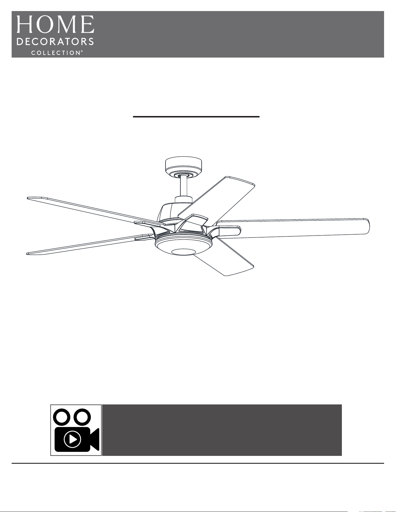
USE AND CARE GUIDE
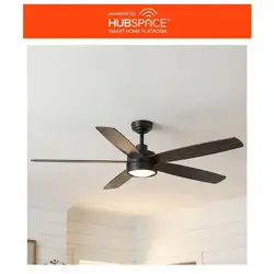
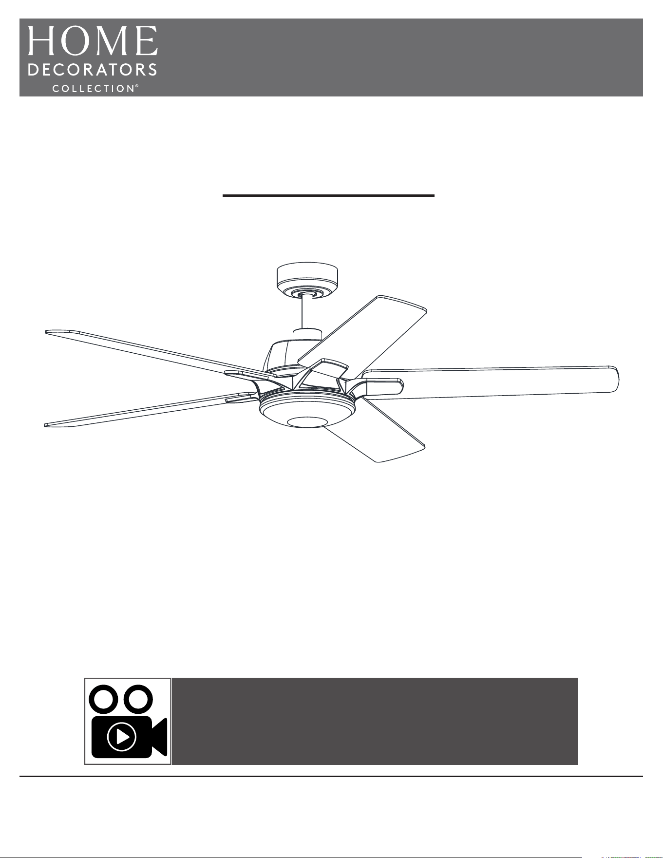
GREENHAVEN 60-INCH CEILING FAN
To view an instructional video on how to install this product:
1. Go to www.homedepot.com and enter either the Item or Model number, found in the top
right corner of the cover of this instruction manual, in the search eld.
2. Click on your product from the list of search results and click on the video link in the
“Product Overview” section.
Questions, problems, missing parts? Before returning to the store,
call Hubspace Customer Service
8 a.m. - 7 p.m., EST, Monday-Friday, 9 a.m. - 6 p.m., EST, Saturday
1-877-592-5233
HOMEDEPOT.COM/HUBSPACE
2
Table of Contents ................................................................2
Safety Information ...............................................................2
Warranty ............................................................................... 3
Pre-Installation ....................................................................3
Installation ............................................................................6
Assembly ..............................................................................7
Operation ...........................................................................15
Care and Cleaning ............................................................. 17
Troubleshooting .................................................................18
1. To reduce the risk of electric shock, ensure the electricity has been
turned off at the circuit breaker or fuse box before you begin.
2. All wiring must be in accordance with the National Electrical Code
ANSI/NFPA 70 and local electrical codes. Electrical installation should
be performed by a qualied licensed electrician.
3. The outlet box and support structure must be securely mounted and
capable of reliably supporting a minimum of 35 lb (15.9 kg). Use
only UL Listed outlet boxes marked “Acceptable for Fan Support of
35 lb (15.9 kg) or less.”
4. The fan must be mounted with a minimum of 7 ft. (2.1 m) of
clearance from the trailing edge of the blades to the oor.
5. Do not place objects in the path of the blades.
6. To avoid personal injury or damage to the fan and other items, use
caution when working around or cleaning the fan.
7. After making electrical connections, spliced conductors should be
turned upward and pushed carefully up into the outlet box. The
wires should be spread apart with the grounded conductor and the
equipment-grounding conductor on one side of the outlet box.
8. All set screws must be checked and retightened where
necessary before installation.
WARNING: To reduce the risk of personal injury, do
not bend the blade brackets (also referred to as
anges) during assembly or after installation. Do
not insert objects in the path of the blades.
WARNING: Electrical diagrams are for reference
only. If you are using a light kit, refer to the light kit
instructions manual to make the electrical
connections. Optional use of any light kit shall be
UL Listed and marked suitable for use with this fan.
WARNING: To avoid possible electrical shock, turn
the electricity off at the main fuse box before
wiring. If you feel you do not have enough electrical
wiring knowledge or experience, contact a licensed
electrician.
Safety Information
Table of Contents
CAUTION: To reduce the risk of personal injury,
use only the screws provided with the outlet box.
WARNING: To reduce the risk of re, electric shock
or personal injury, mount to outlet box marked
“Acceptable for fan support of 35 lb (15.9 kg) or
less”, and use screws provided with the outlet box.
READ AND SAVE THESE INSTRUCTIONS.
WARNING: To reduce the risk of re or electric
shock, this fan should only be used with fan speed
control part no. JY1156H-LD-F1-EL, manufactured
by Chungear Industrial Co., Ltd.
WARNING: To reduce the risk of electric shock, this
fan must be installed with an isolating wall switch.
3
HOMEDEPOT.COM/HUBSPACE
Please contact 1-877-592-5233 for further assistance.
Pre-Installation
Warranty
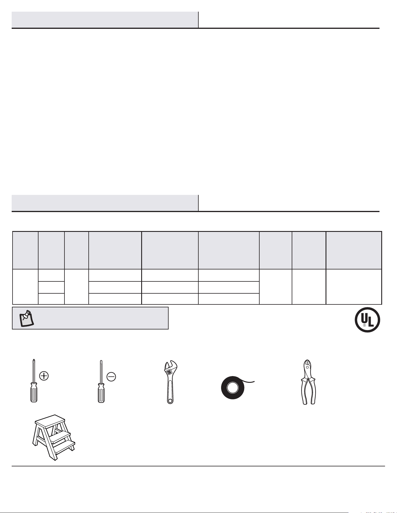
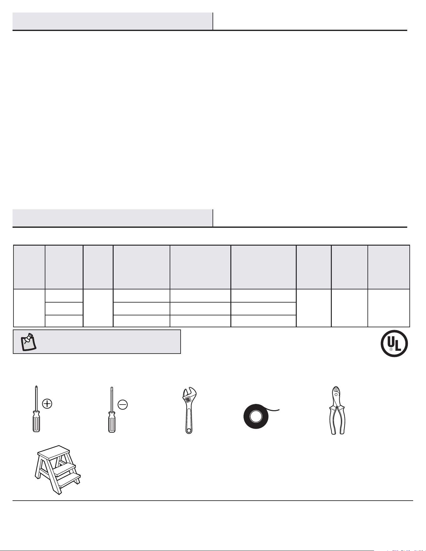
SPECIFICATIONS
NOTE: These are approximate measures. They do not
include the amps and wattage used by the light kit.
Size Speed Volts
Fan Power
Consumption
(without lights)
WATT
Airow
CFM
Airow Efciency
(higher is better)
CFM/WATT
Net
Weight
Gross
Weight
Cubic Feet
60 in.
Low
120
4 2142 535
17.64 lb
(8 kg)
23.59 lb
(10.7 kg)
2.19 cu. ft.
Medium 11 4287 389
High 40 6668 166
TOOLS REQUIRED
Phillips
screwdriver
Flat blade
screwdriver
Adjustable
wrench
Electrical
tape
Wire
cutter/
stripper
Step ladder
The supplier warrants the fan motor to be free from defects in workmanship and material present at time of shipment from the factory for a
lifetime after the date of purchase by the original purchaser. The supplier warrants that the light kit, excluding any glass, to be free from defects in
workmanship and material at the time of shipment from the factory for a period of ve years after the date of purchase by the original purchaser.
The supplier also warrants that all other fan parts, excluding any glass or acrylic blades, to be free from defects in workmanship and material at the
time of shipment from the factory for a period of two years after the date of purchase by the original purchaser. We agree to correct such defects
without charge or at our option replace with a comparable or superior model if the product is returned. To obtain warranty service, you must present
a copy of the receipt as proof of purchase. All costs of removing and reinstalling the product are your responsibility. Damage to any part, such as by
accident, misuse, improper installation, or by afxing any accessories, is not covered by this warranty. Because of varying climatic conditions this
warranty does not cover any changes in brass nish, including rusting, pitting, corroding, tarnishing, or peeling. Brass nishes of this type give their
longest useful life when protected from varying weather conditions. A certain amount of “wobble” is normal and should not be considered a defect.
Servicing performed by unauthorized persons shall render the warranty invalid. There is no other express warranty. Home Decorators Collection
hereby disclaims any and all warranties, including but not limited to those of merchantability and tness for a particular purpose to the extent
permitted by law. The duration of any implied warranty which cannot be disclaimed is limited to the time period as specied in the express warranty.
Some states do not allow a limitation on how long an implied warranty lasts, so the above limitation may not apply to you. The retailer shall not be
liable for incidental, consequential, or special damages arising out of or in connection with product use or performance except as may otherwise
be accorded by law. Some states do not allow the exclusion of incidental or consequential damages, so the above exclusion or limitation may not
apply to you. This warranty gives specic legal rights, and you may also have other rights which vary from state to state. This warranty supersedes
all prior warranties. Shipping costs for any return of product as part of a claim on the warranty must be paid by the customer.
Contact the Customer Service Team at 1-877-592-5233 or visit www.HomeDepot.com/hubspace.
4
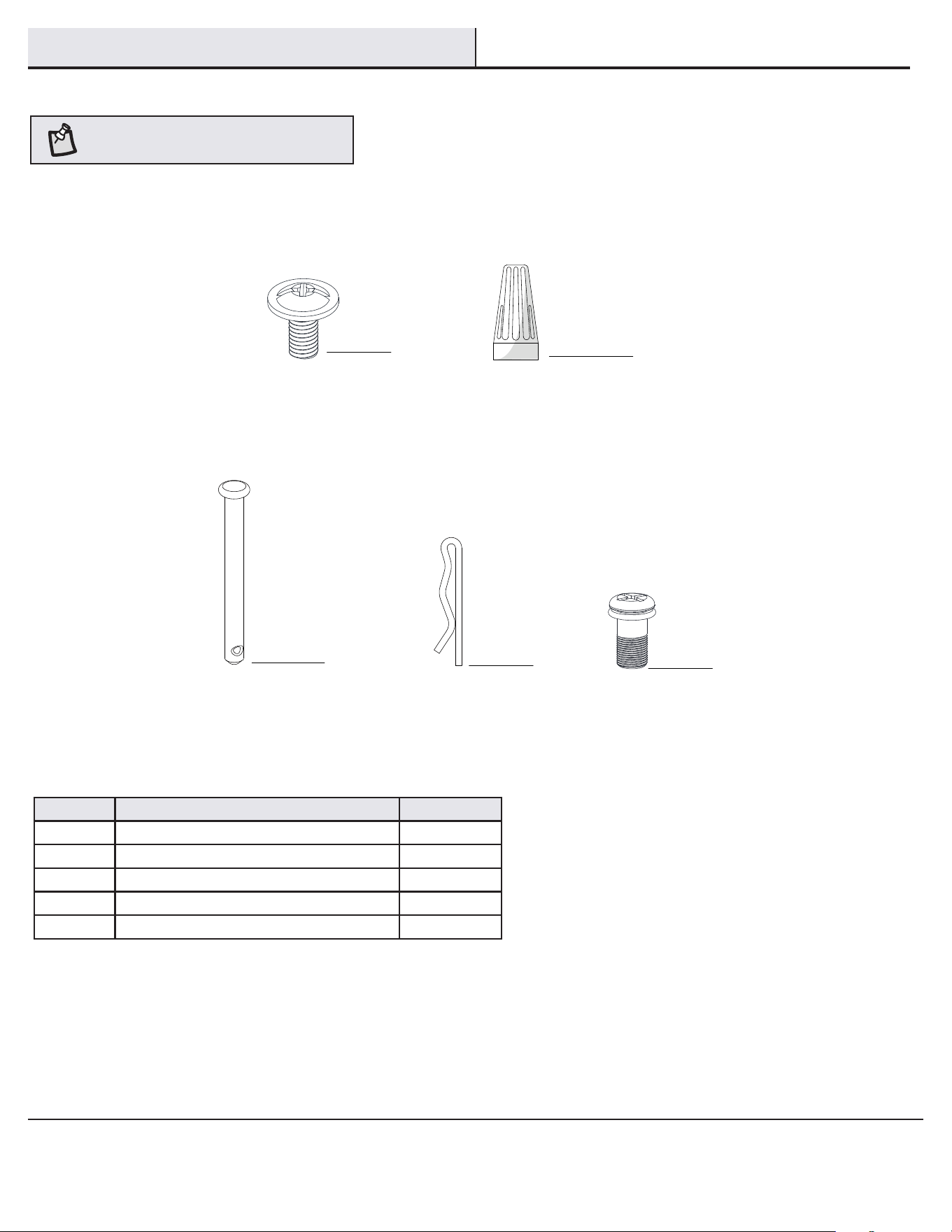
Part Description Quantity
AA Blade attachment screws 16
BB Plastic wire connecting nut 3
CC Hanger pin 1
DD Locking pin 1
EE Extra blade bracket screw 1
Pre-Installation (continued)
HARDWARE INCLUDED
NOTE: Hardware not shown to actual size.
BB
CC
DD
AA
EE
5
HOMEDEPOT.COM/HUBSPACE
Please contact 1-877-592-5233 for further assistance.
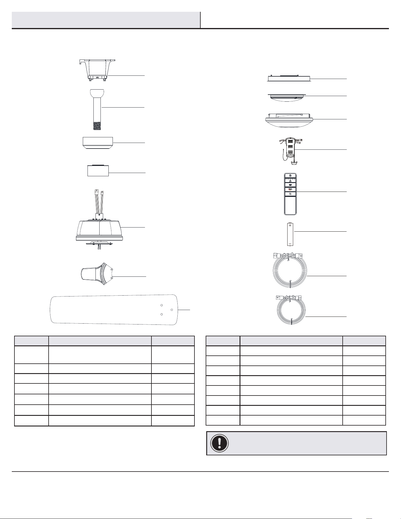
Part Description Quantity
A
Slide-on mounting bracket
(inside canopy)
1
B Ball/downrod assembly 1
C Canopy 1
D Decorative motor collar cover 1
E Fan motor assembly 1
F Blade bracket 5
G Blade 5
Part Description Quantity
H Light kit pan 1
I Light kit tter assembly 1
J Glass shade 1
K Receiver 1
L Remote control 1
M Battery 2
N 3-pin extension wire (66 in.) 1
O 2-pin extension wire (66 in.) 1
IMPORTANT: This product and/or components are governed by
one or more of the following U.S. Patents: 5,947,436; 5,988,580;
6,010,110; 6,046,416; 6,210,117 and other patents pending.
Pre-Installation (continued)
PACKAGE CONTENTS
L
M
N
O
H
I
J
K
B
C
D
E
F
G
A
6
Installation
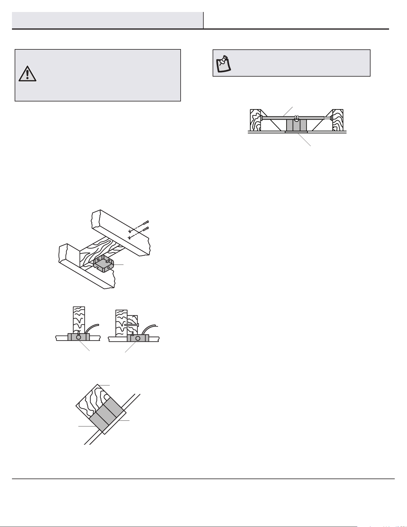
MOUNTING OPTIONS
WARNING: To reduce the risk of re, electric shock
or personal injury, mount to an outlet box marked
“Acceptable for fan support of 35 lb (15.9 kg) or less”,
and use screws provided with the outlet box. An outlet
box commonly used for the support of lighting xtures
may not be acceptable for fan support and may need to
be replaced. If in doubt, consult a qualied electrician.
If your ceiling fan does not have an existing UL Listed mounting
box, then install one using the following instructions:
□ Disconnect the power by removing the fuses or turning off
the circuit breakers.
□ Secure the outlet box directly to the building structure. Use
the appropriate fasteners and materials. The outlet box and
support structure must be securely mounted and capable of
reliably supporting a minimum of 35 lb (15.9 kg). Use only UL
Listed outlet boxes marked “Acceptable for fan support of
35 lb (15.9 kg) or less.” Do not use a plastic outlet box.
The illustrations below show three different ways to mount the
outlet box.
If the canopy (C) touches the ball/downrod assembly (B), then remove
the decorative motor collar cover (D), and turn the canopy (C) 180°
before attaching the canopy (C) to the mounting plate.
To hang your fan where there is an existing xture but no ceiling joist,
you may need an installation hanger bar as shown above
(available at any Home Depot store).
NOTE: You may need a longer downrod to maintain
proper blade clearance when installing on a steep, sloped
ceiling. The maximum angle allowable is 15° away from
horizontal.
Outlet Box
Outlet Box
Recessed
Outlet
Box
Provide Strong
Support
Ceiling
Mounting
Plate
Outlet Box
Hanger Bar
7
HOMEDEPOT.COM/HUBSPACE
Please contact 1-877-592-5233 for further assistance.
Assembly - Standard Ceiling Mount
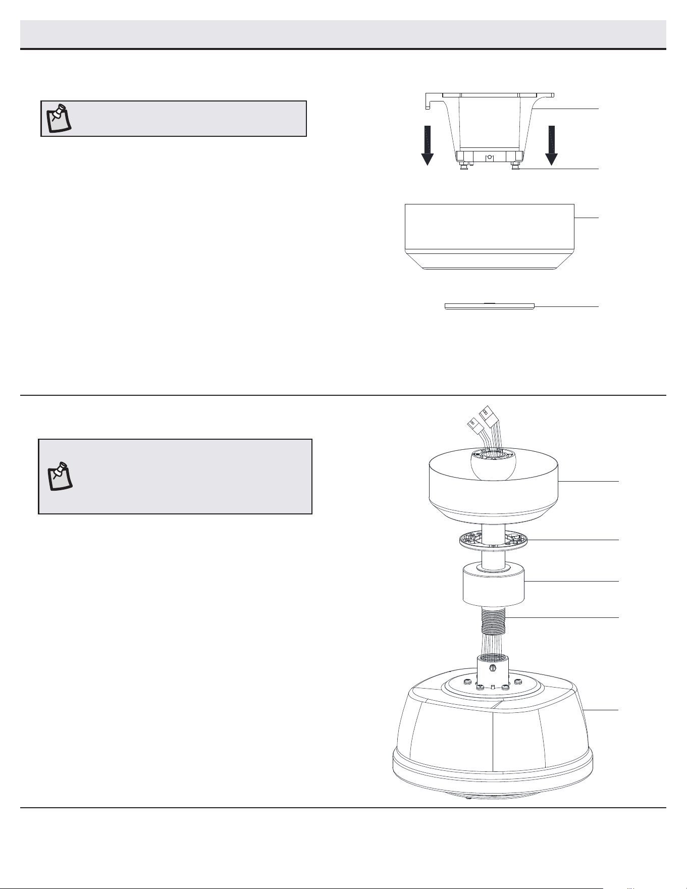
Routing the wires
Preparing for mounting
□ Remove the magnetic canopy bottom cover (JJ) from the
canopy (C) by pulling it off.
□ Loosen the two canopy screws (FF) located in the bottom of
the slide-on mounting bracket (A).
□ Turn the slide-on mounting bracket (A) counterclockwise and
lift it up to remove the slide-on mounting bracket (A) from the
canopy (C).
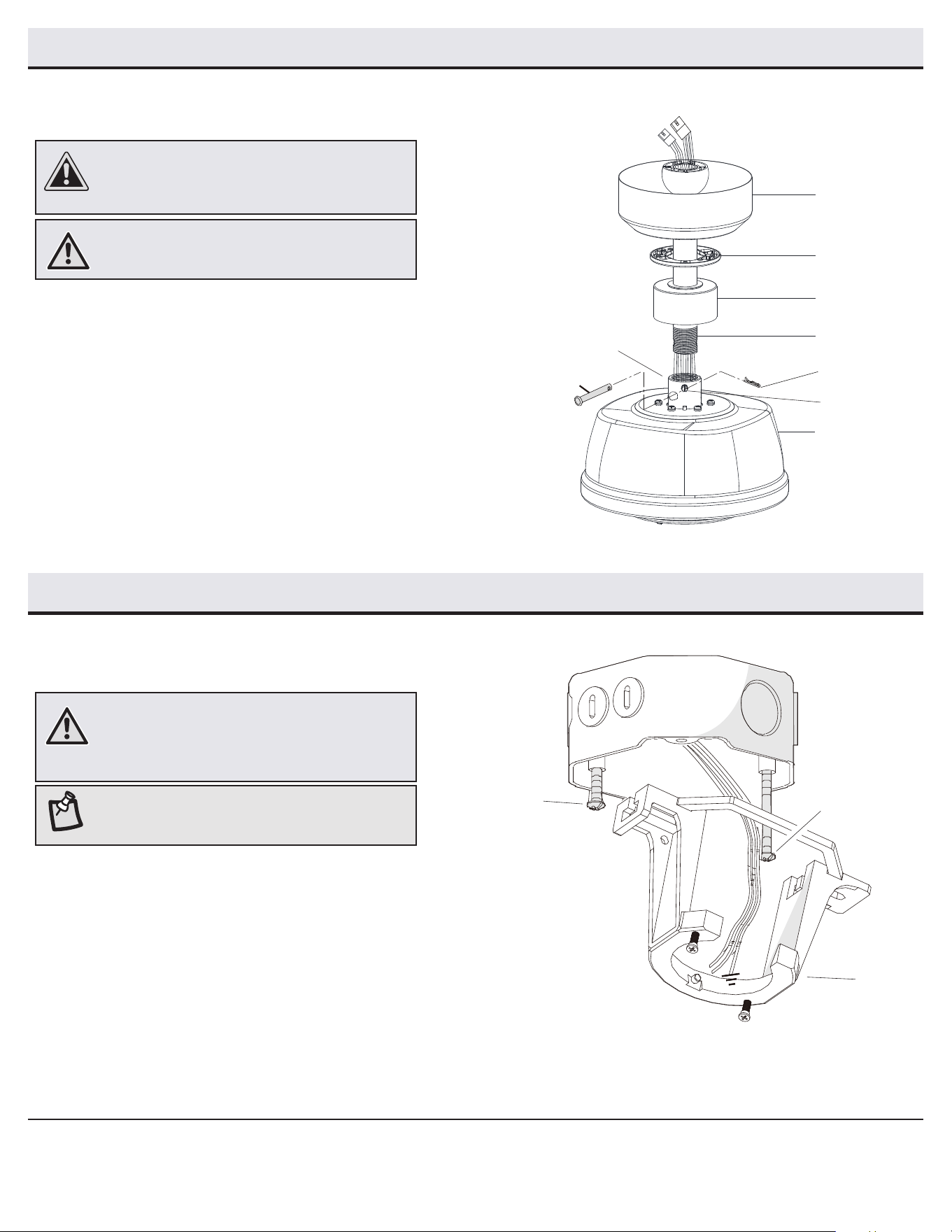
□ Route the wires exiting the top of the fan motor assembly (E)
through the decorative motor collar cover (D) and then the center
of the canopy bottom cover (JJ).
□ Make sure the opening of canopy (C) is on top and insert the ball/
downrod assembly (B) through the canopy (C).
□ Route the wires exiting the top of the fan motor assembly (E)
through the downrod as shown.
2
1
NOTE: The fan comes with 12 in. lead wires for use with the
provided 6 in. ball/downrod assembly (B). If you wish to use
a longer downrod, attach the 3-pin extension wire (N) and
2-pin extension wire (O) to the fan by connecting the molded
adaptor plugs from the extension wires to the 3-pin and
2-pin adaptor plugs from the fan.
NOTE: The magnet is pre-attached on the canopy
bottom cover for you to remove and install easily.
C
D
E
JJ
B
FF
C
A
JJ
8
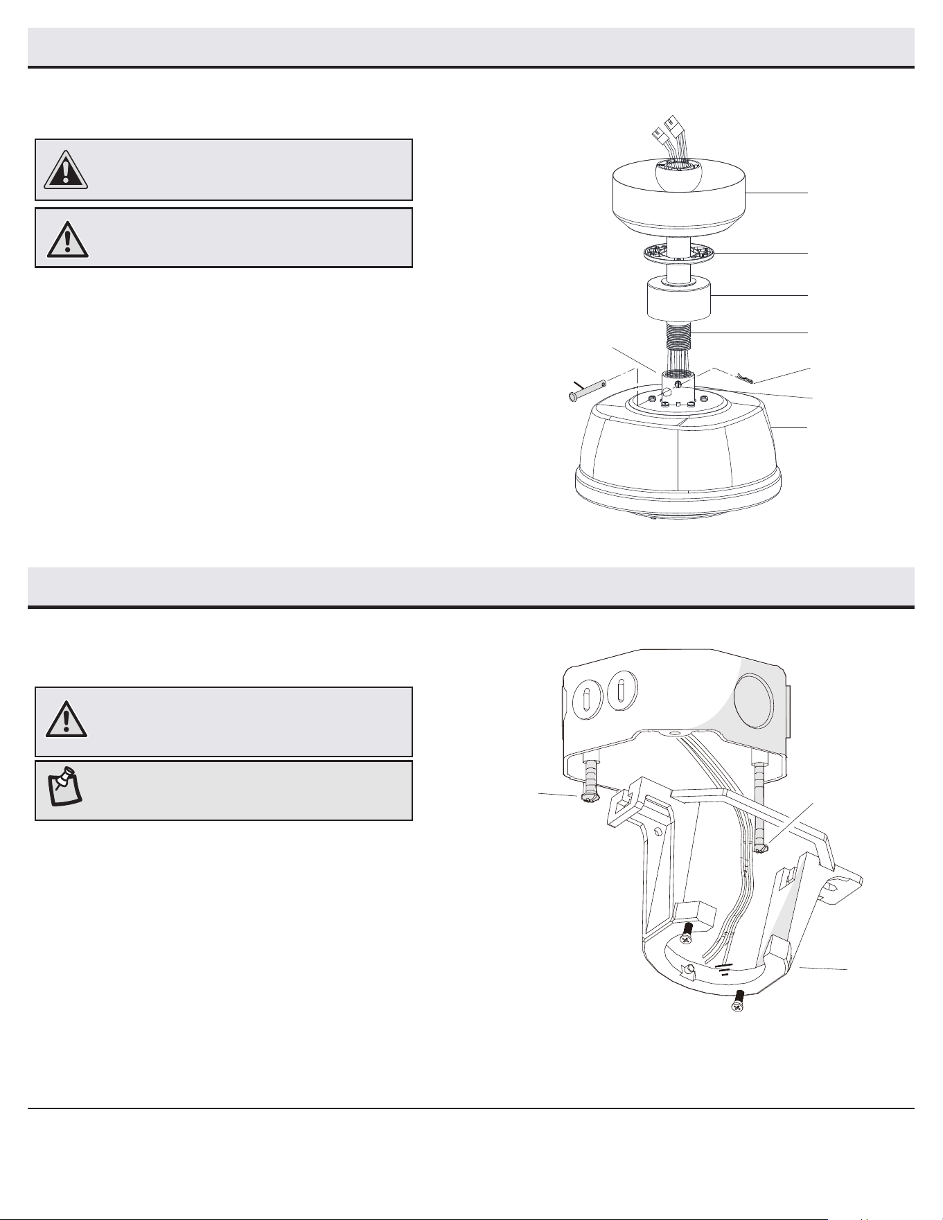
Attaching the fan to the
electrical box
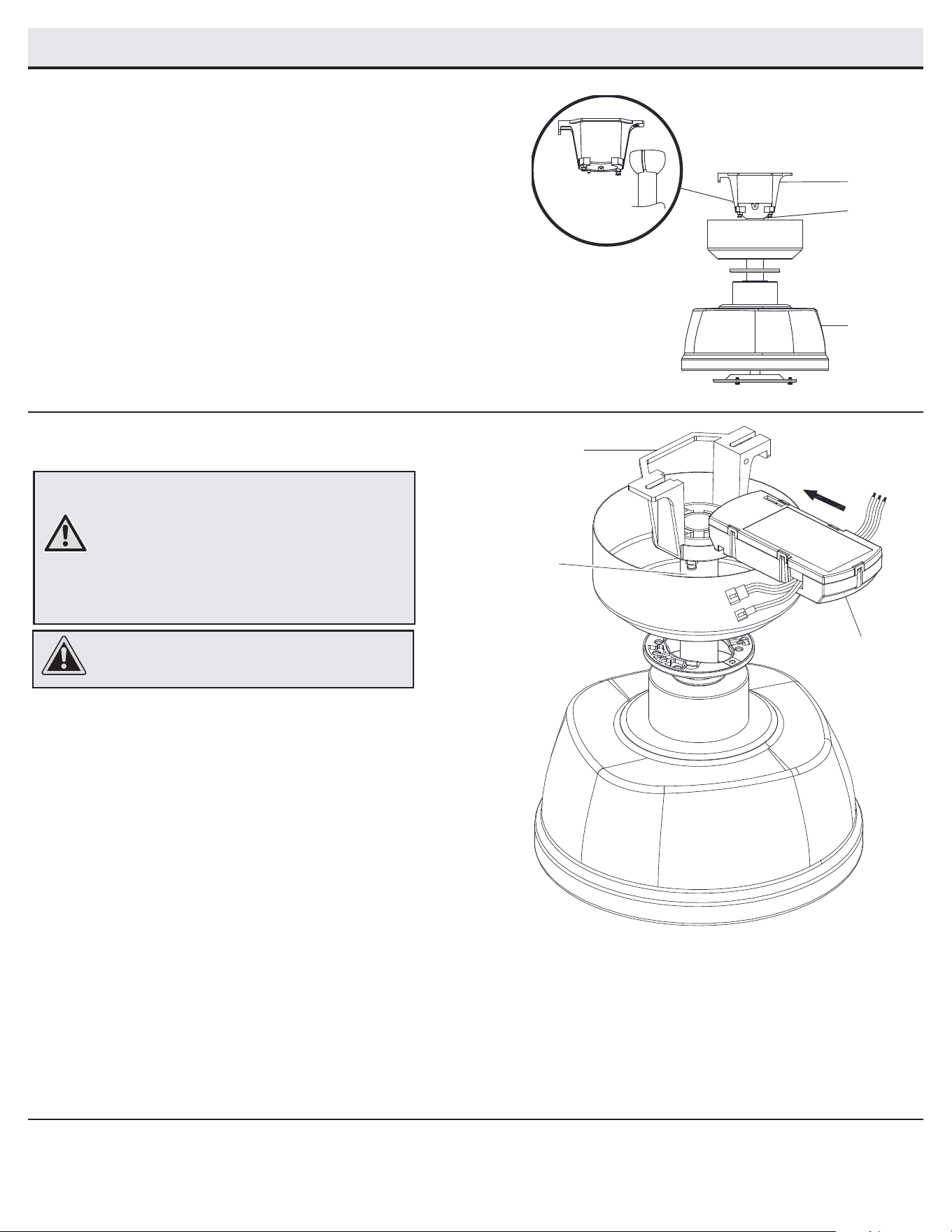
□ Loosen the two mounting screws (GG) in the outlet box.
□ Pass the 120-Volt supply wires through the center hole in the
slide-on mounting bracket (A).
□ Slide the slide-on mounting bracket (A) on to the mounting
screws (GG) and center the slide-on mounting bracket (A) in
relation to the outlet box. If necessary, use leveling washers
(not included) between the slide-on mounting bracket (A) and
the outlet box. The at side of the slide-on mounting bracket (A)
should face toward the outlet box, as shown.
□ Securely tighten the two mounting screws (GG).
1
WARNING: To reduce the risk of re, electric shock
or personal injury, mount to an outlet box marked
“Acceptable for fan support of 35 lb (15.9 kg) or less”,
and use screws provided with the outlet box.
NOTE: The slide-on mounting bracket (A) is designed
to slide into place on an outlet box with the outlet box
screws (GG) installed.
Assembly - Standard Ceiling Mount (continued)
Assembling the fan
□ Loosen, but do not remove, the set screws (KK) on the collar (PP) on
top of the fan motor assembly (E).
□ Install the ball/downrod assembly (B) by inserting it into the motor
collar (PP), and turning it clockwise until the holes at the bottom of
the ball/downrod assembly (B) align with the holes in the collar on
top of the fan motor assembly (E).
□ Carefully insert the hanger pin (CC) through the holes in the collar
(KK) and ball/downrod assembly (B). Be careful not to jam the hanger
pin (CC) against the wiring inside the ball/downrod assembly (B).
□ Insert the locking pin (DD) through the hole near the end of the
hanger pin (CC) until it snaps into its locked position.
□ Re-tighten the set screws (KK) on the collar (PP) on top of the fan
motor assembly (E).
WARNING: Failure to properly install the locking
pin (DD) could result in the fan becoming loose and
possibly falling.
CAUTION: To ensure wobble-free operation and to avoid
damage to the fan, the ball/downrod assembly (B) and the
set screw (KK) must be completely tightened.
3
Assembly - Hanging the Fan
C
D
E
JJ
B
CC
DD
KK
PP
A
GG
GG
9
HOMEDEPOT.COM/HUBSPACE
Please contact 1-877-592-5233 for further assistance.
Assembly - Hanging the Fan (continued)
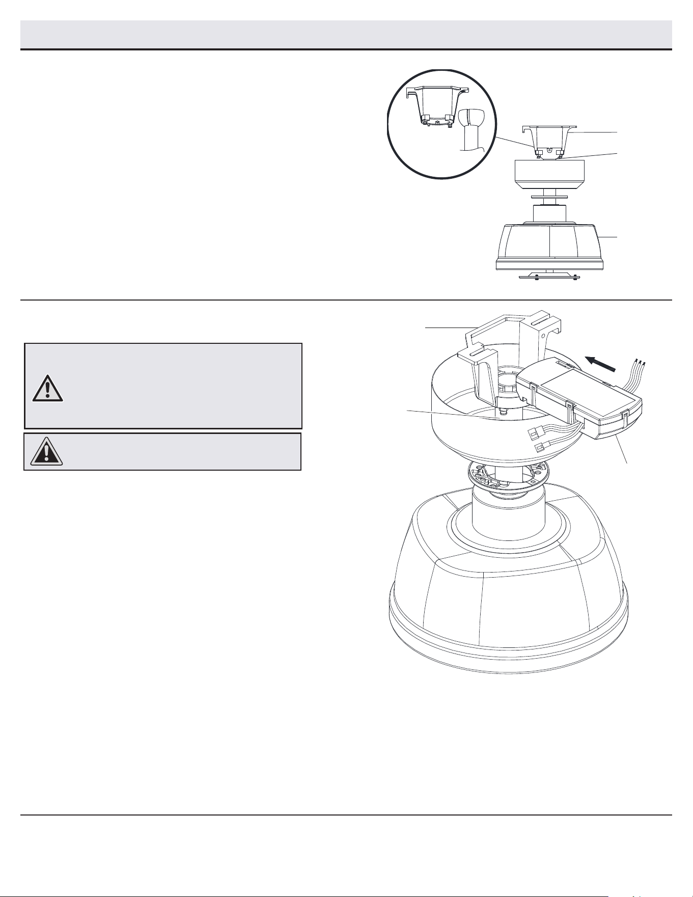
Hanging the fan
□ Carefully lift the fan motor assembly (E) up to the slide-on
mounting bracket (A).
□ Insert the ball portion of the ball/downrod assembly (B)
into the socket of the slide-on mounting bracket (A).
□ Turn the ball/downrod assembly (B) clockwise until it is
seated with the tab of the slide-on mounting bracket (A)
aligned with the slot in the ball.
2
B
A
E
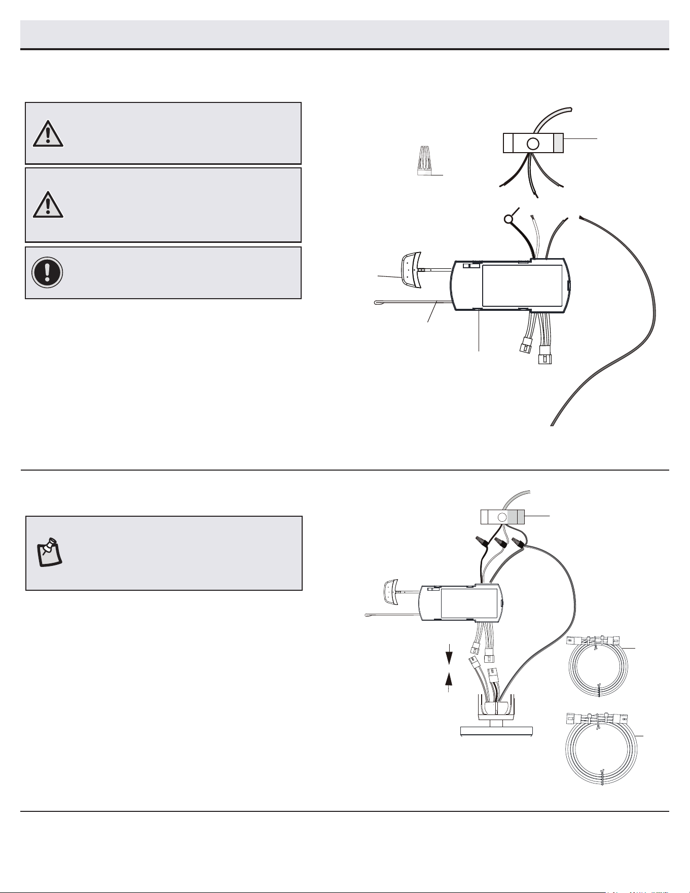
Installing the receiver
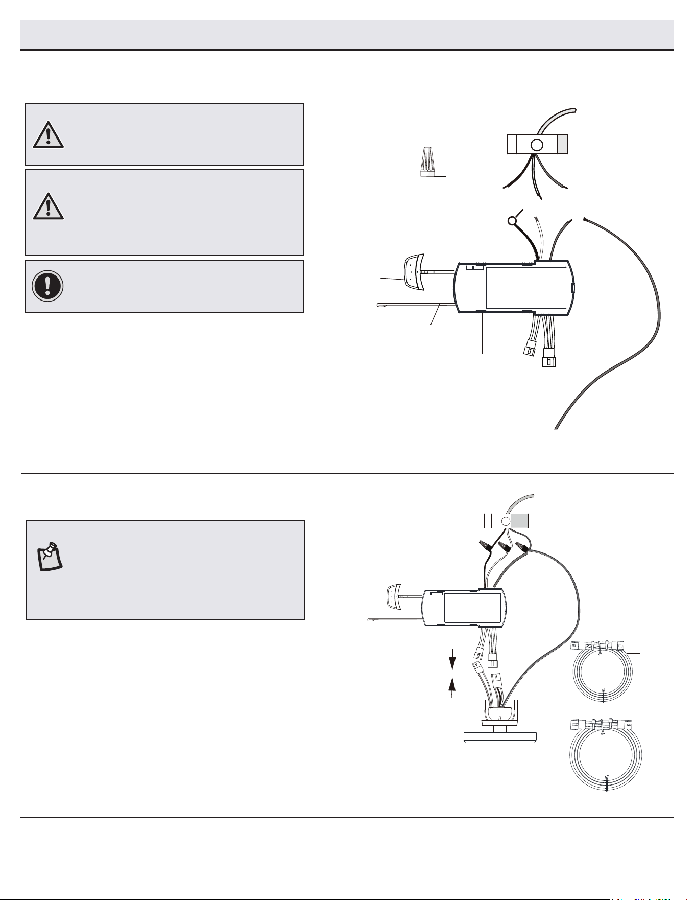
□ Position the house supply wires to one side of the
slide-on mounting bracket (A). Position the fan wires
to the opposite side.
□ Insert the narrow end of the receiver (K) (as shown,
at side towards the ceiling) into the slide-on
mounting bracket (A) until it rests on top of the ball/
downrod assembly (B).
3
WARNING: To reduce the risk of re or electric shock,
remember to disconnect power. The electrical wiring
must meet all local and national electrical code
requirements. The electrical source and fan must
be 110/120 volts, 60Hz. Do not use this product in
conjunction with any variable wall control. Incorrect
wire connection can damage this receiver.
CAUTION: If other fan wires are a different color, have
this unit installed by a licensed electrician.
A
K
B
10
Assembly - Hanging the Fan (continued)
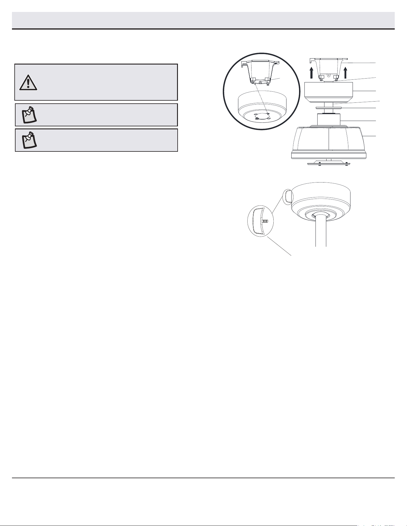
Wiring the fan to the receiver
5
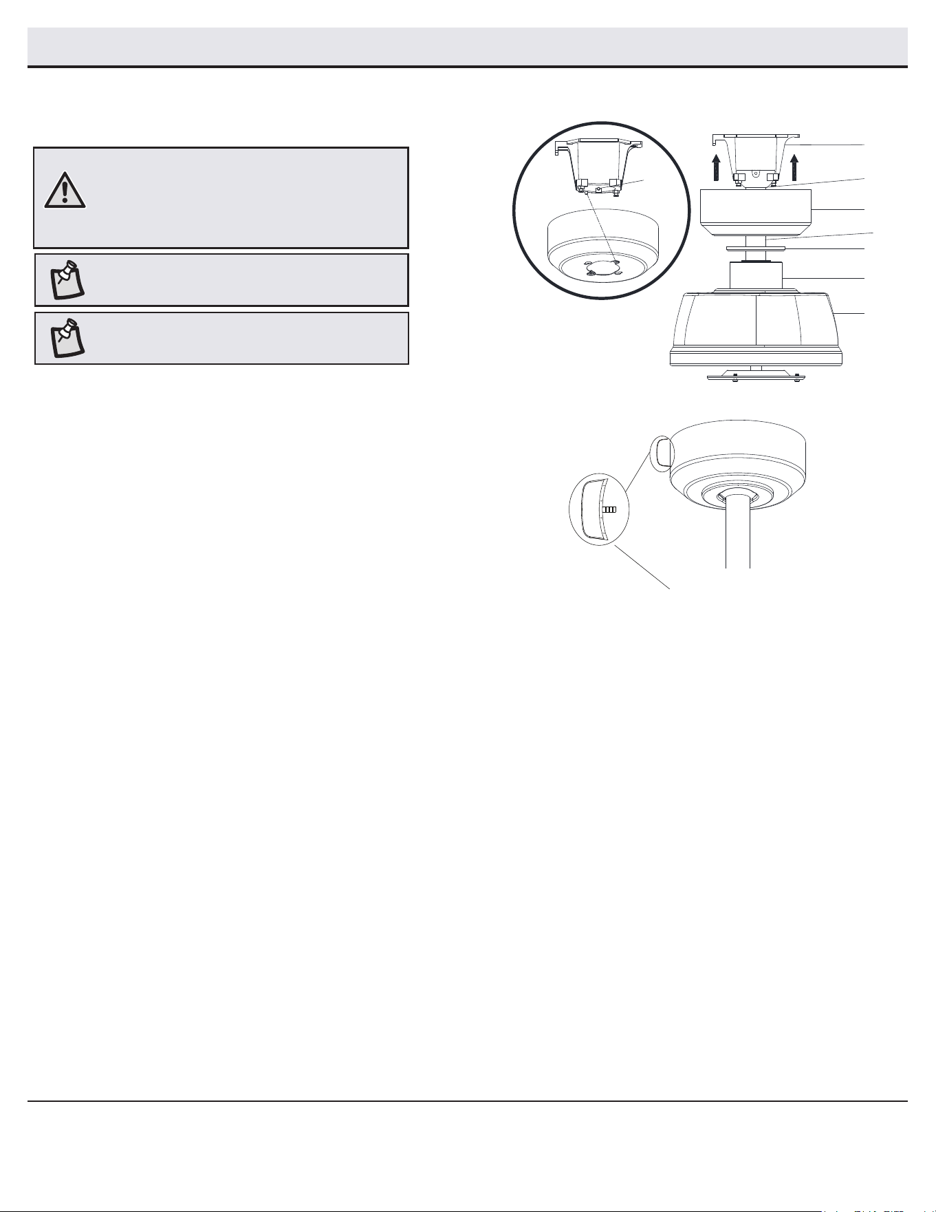
□ If using the 6 in. ball/downrod assembly (B) provided, wire the
receiver to the fan wires by connecting the molded adaptor
plug from the receiver (K) with the molded adaptor of the fan
motor assembly (E) together.
□ If you wish to use longer downrod, you can use the extension
lead wire (66 in.) (O) and (N) provided by connecting the
molded adaptor together.
Wiring the receiver to the
household wiring
4
WARNING: To avoid possible electrical shock, turn
the electricity off at the main fuse box before
wiring. If you feel you do not have enough electrical
wiring knowledge or experience, contact a licensed
electrician.
WARNING: Each wire nut supplied with this fan is
designed to accept up to one 12-gauge house wire
and two wires from the fan. If you have larger than
12-gauge house wiring or more than one house wire to
connect to the fan wiring, consult an electrician for the
proper size wire nuts to use.
IMPORTANT: Use the wire connecting nuts (BB)
supplied with your fan. Secure the connectors with
electrical tape and ensure there are no loose strands
or connections.
□ Spread the wires apart so that the green and white wires
are on one side of the outlet box and the black wire is on the
other side.
□ Connect the green fan wires to the household ground wire
(this may be a green or bare wire) using a wire connecting
nut (BB).
□ Connect the receiver (K) black (or red) wire to the household
black (hot) wire using a wire connecting nut (BB).
□ Connect the receiver (K) white wire to the household white
wire (neutral) using a wire connecting nut (BB).
□ Secure each wire connecting nut using electrical tape.
NOTE: The fan comes with 12 in. lead wires for use with
the provided 6 in. ball/downrod assembly (B). If you wish
to use a longer downrod, attach the 3-pin extension wire
(N) and 2-pin extension wire (O) to the fan by connecting
the molded adaptor plugs from the extension wires to
the 3-pin and 2-pin adaptor plugs from the fan.
N
O
Outlet box
Green
Black
Black
Green (or Bare)
Green
Outlet Box
Receiver
Antenna
White
K
BB
Green
Wi-Fi
Antenna
11
HOMEDEPOT.COM/HUBSPACE
Please contact 1-877-592-5233 for further assistance.
Assembly - Hanging the Fan (continued)
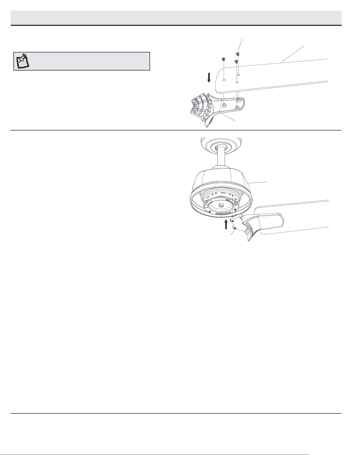
Mounting the fan motor assembly
(standard mount)
6
WARNING: When using the standard ball/downrod
mounting, the tab in the ring at the bottom of the slide-
on mounting bracket (A) must rest in the groove of
the hanger ball. Failure to properly seat the tab in the
groove could cause damage to the wiring.
NOTE: The magnet is pre-attached on the canopy bottom
cover for you to remove and install easily.
□ Align the locking slots of the canopy (C) with the two screws
(FF) and alignment post (QQ) in the slide-on mounting bracket
(A).
□ Push up the canopy (C) and turn it clockwise until the alignment
post (QQ) engages to the round hole and the screws (FF) engage
to the key slots.
□ Firmly tighten the two mounting screws (FF).
□ Align the oval shape on the canopy (C) with canopy bottom
cover (JJ).
□ Push up the canopy bottom cover (JJ) until the screw (FF) heads
engage to the slots on the canopy bottom cover (JJ) so that
the magnetic canopy bottom cover (JJ) can be attached to the
bottom of the canopy (C) properly.
NOTE: For better performance with the Wi-Fi system, the
Wi-Fi antenna must be mounted to the ceiling outside of
the fan’s ceiling canopy.
QQ
A
B
E
C
JJ
FF
View after installation
Wi-Fi antenna mount
outside of the canopy
D
12
Assembly - Attaching the Fan Blades
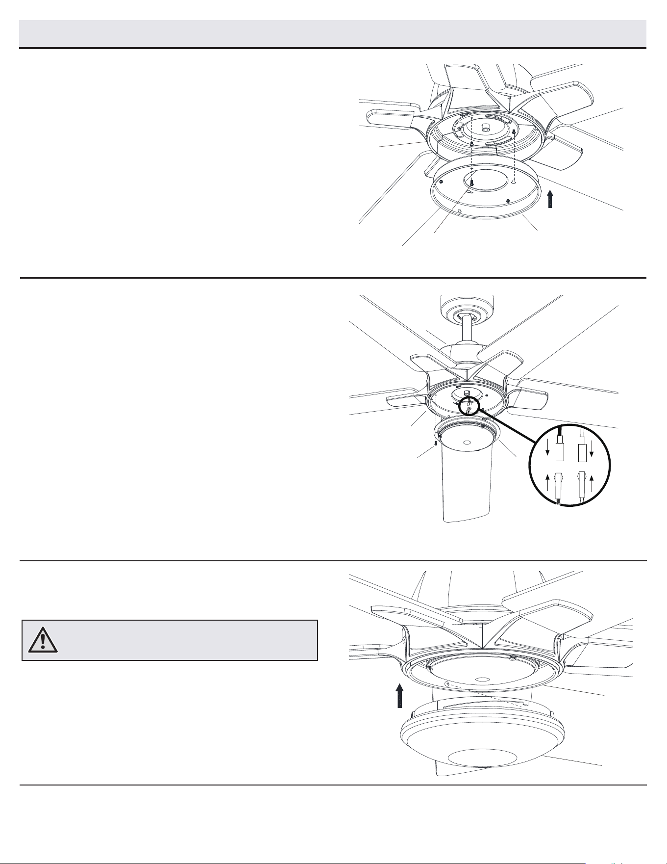
Attaching the fan blades to the
blade brackets
1
□ Attach a blade (G) to blade bracket (F) by inserting the blade
attachment screws (AA) into the holes in the blade (G) and
through the blade bracket (F).
□ Tighten each screw securely.
□ Repeat this step for each blade and blade bracket.
NOTE: Your fan blades are reversible. Select the blade
side nish which best accentuates your decor.
Fastening the blade assemblies to
the motor
2
□ Fasten the blade/blade bracket assembly to the fan motor
assembly (E) by inserting the alignment posts into the slot on
the bottom of the motor and tightening the pre-installed blade
bracket screws (EE).
□ Repeat these steps for the remaining blades.
AA
G
F
EE
E
13
HOMEDEPOT.COM/HUBSPACE
Please contact 1-877-592-5233 for further assistance.
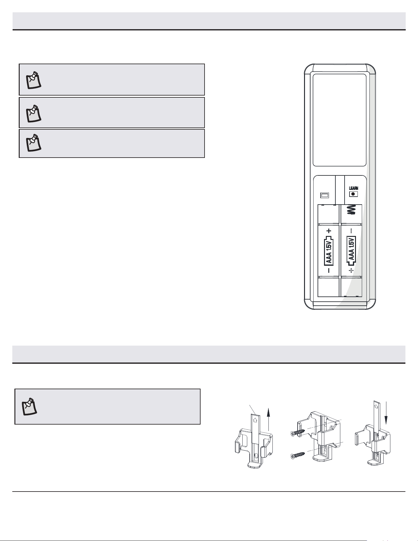
Attaching the light kit tter assembly
2
□ Remove one screw (TT) from the light kit pan (H), and loosen,
but do not remove, the other two screws.
□ Connect the wires from the light kit tter assembly (I) to the
wires from the fan motor assembly (E) by connecting the
molded adaptor plugs together. Carefully tuck all wires and
splices into the switch cup.
□ Push the light kit tter assembly (I) up to the light kit pan (H)
so that the two loosened screw heads t into the keyhole
slots. Turn the light kit tter assembly (I) clockwise to secure.
□ Re-install the screw that was removed in the rst step.
□ Make sure all the screws are rmly tightened.
Installing the glass shade
3
□ Place the glass shade (J) into the light kit pan (H), aligning the
three at areas on the top of the ange of the glass shade (J)
with the three raised dimples in the light kit pan (H). Turn the
shade clockwise until it stops.
WARNING: Do not overtighten when installing the glass shade
into the light kit. Allow the glass shade to cool completely before
removing.
Installing the light kit pan
1
□ Remove one screw (OO) from the black bracket below the fan
motor assembly (E), and loosen but do not remove the other
two screws.
□ Push the light kit pan (H) up to the fan motor assembly (E) so
that the two loosened screw heads t into the keyhole slots.
Turn the light kit pan (H) clockwise.
□ Re-install the screw (OO) that was removed in the rst step.
□ Make sure all the screws are rmly tightened.
Assembly - Attaching the Light Kit
H
E
OO
J
H
I
TT
H
E
14
Assembly - Attaching the Accessories
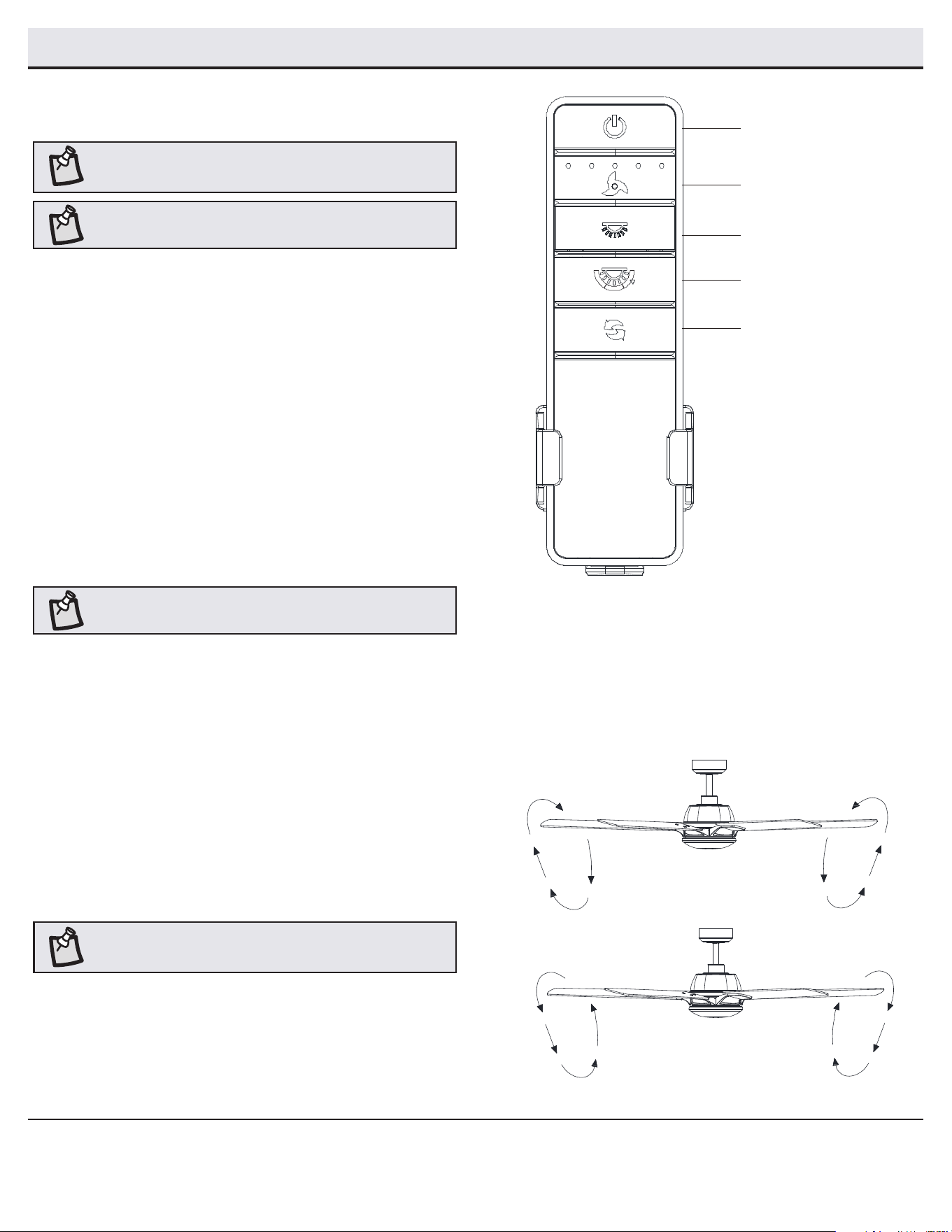
Mounting the remote control holder
□ Slide the screw cover plate up to remove it from the wall
cradle.
□ Position the wall cradle in the desired position and attach it to
the wall using the included wall cradle screws.
□ Slide the screw cover plate back onto the wall cradle to
conceal the screws.
Screw cover plate
NOTE: Screw wall anchors are included for extra support. The
included screws are designed to screw easily into the wall. If
you would like a more permanent or secure hold, install the wall
anchors prior to attaching the wall cradle to the wall.
Preparing the remote control
□ Conrm that the power to the fan is off at either the wall switch or breaker box.
□ Remove the battery cover by pressing rmly on the arrow and sliding the cover off.
□ Install two 1.5V AAA batteries (M).
□ Return power to the fan at the wall switch or breaker box.
□ If the remote control doesn’t work as normal, press then release the “Learn” button for 1-2
seconds (located in the remote’s battery compartment) within 30 seconds of turning on the
power.
□ If pairing is successful, the fan’s light kit will ash and the blades will begin to spin.
□ Replace the battery cover on the remote control.
1 to 3 mode
□ To use more than one remote control for your fan, press the “Learn” button for 10 seconds and release
within 30 seconds of turning on the power. Once pairing is successful, the fan’s light kit will ash and the
blades will begin to spin.
□ Repeat the above process for the remote controls you want to work with this fan.
□ The fan can be only controlled by 3 remote controls maximum at the same time after “Learning”. If you
use a fourth remote control to handle the fan, the rst remote control will be replaced.
1 to 1 mode
□ To use only one remote control for your fan, press and release the “Learn” button for 1-2 seconds within
30 seconds of turning on the power. The “1 to 3” mode will be cleared and returned back to “1 to 1” mode.
NOTE: The remote control has already been paired to the ceiling
fan for your convenience. If you have two of the same model fans
in your home, please follow the steps below to control each fan
independently.
NOTE: The remote control battery will weaken with age and
should be replaced before leaking takes place, as this will damage
the remote control. Dispose of used battery properly and keep the
battery out of the reach of children.
NOTE: The switch marked “D/O” controls the dimming function
of the lights. If you wish to use the dimming functionality or
Hubspace app, keep the switch in the “D” position. To disable the
dimming function, set the switch to the “O” position.
D O
Assembly - Preparing the Remote Control
15
HOMEDEPOT.COM/HUBSPACE
Please contact 1-877-592-5233 for further assistance.
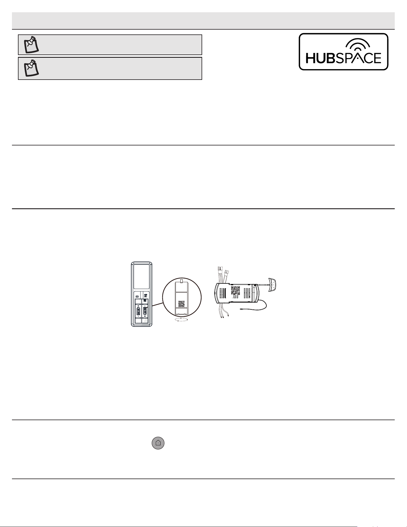
Operating Your Fan and Remote Control
POWER ON/OFF
Press and release the power button to turn the fan and light on or off.
LIGHT ON/OFF/DIMMING
Press and release the button to turn the light on or off.
Press and hold the button to activate the dimmer function.
CORRELATED COLOR TEMPERATURE (CCT) CHANGING
Push and release the button to cycle through the six color temperature
options.
Option 1: 2700K (Warm White).
Option 2: 3000K (Soft White).
Option 3: 3500K (Neutral White).
Option 4: 4000/4100K (Cool White).
Option 5: 5000K (Daylight).
Option 6: 6500K (Daylight Deluxe).
NOTE: The default temperature of the ceiling fan light is 3000k
(Soft White).
Power
(fan and light on/off)
Light on/off/dimming
Fan speed
CCT changing
Fan reverse
FAN SPEED
LEDs on the fan speed button will illuminate to the corresponding speed.
Press and release 1 time: turns the fan speed to 5.
Press and release 2 times: turns the fan speed to 4.
Press and release 3 times: turns the fan speed to 3.
Press and release 4 times: turns the fan speed to 2.
Press and release 5 times: turns the fan speed to 1.
Press and release 6 times: turns the fan off.
NOTE: The remote receiver includes a memory function that will
return the fan to its last setting when turned on via the power
button.
FAN REVERSE
Press and release the fan reverse button to reverse the rotation of your
ceiling fan.
Warm weather (Forward) - A downward airow creates a cooling effect.
This allows you to set your air conditioner on a higher setting without
affecting your comfort.
Cool weather (Reverse) - An upward airow moves warm air off of the
ceiling. This allows you to set your heating unit on a lower setting without
affecting your comfort.
NOTE: Do not wait for the fan to stop before pressing the reverse
button. The fan will not reverse direction if the fan is not moving.
Warm weather
Cool weather
NOTE: On start up your ceiling fan will oscillate back and forth.
This is NORMAL OPERATION for DC ceiling fans as it goes
through its calibration cycle. The fan is NOT DEFECTIVE.
16
Application Set-Up
NOTE: For more information on smart remote set up, please refer
to the quick start guide located in the remote pack.
NOTE: To use Alexa to change the color temperature of the light,
please make sure the light is turned on rst.
Questions, problems missing parts?
Please call Hubspace Customer service
8 a.m. - 7 p.m. EST, Monday - Friday;
9 a.m. - 6 p.m., EST, Saturday
(877) 592-5233
□ Download the Hubspace™ app from the App Store or the Google Play Store to your mobile device.
□ Launch the app.
□ To register, enter your email address and a password. Or, login if you already have an account.
□ Bluetooth access is required for device setup.
Getting started
1
□ Hubspace only shows Wi-Fi networks that your device can use. Check your network only if an option does not appear during set up.
□ This Hubspace device requires a 2.4GHz Wi-Fi channel.
□ Most routers provide a 2.4 GHz Wi-Fi channel.
□ If you do not see your Wi-Fi network name when you attempt to connect your device, please check your router settings.
Verify your network
2
□ In the Hubspace app, tap the plus sign in the upper right corner.
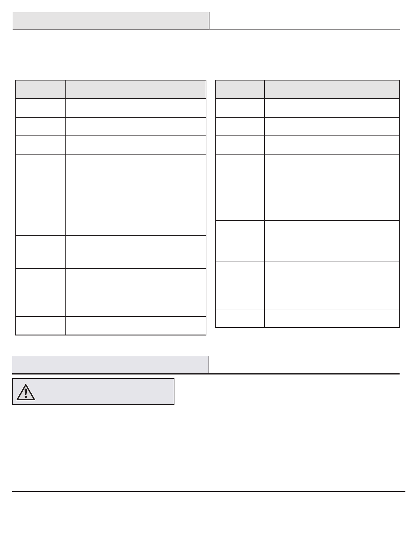
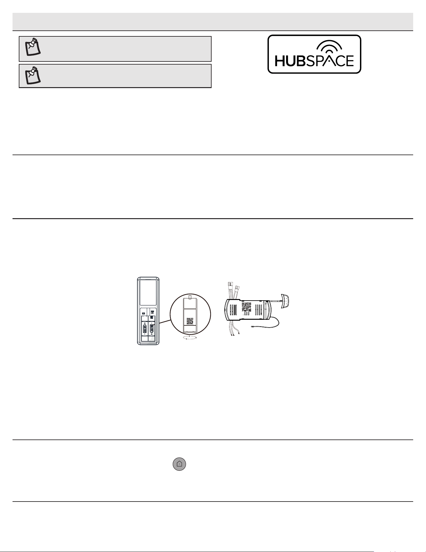
□ Scan your product’s QR code. You can nd the QR code on the remote receiver, inside the battery
compartment cover of the remote, and on the Quick Start Guide paper included with the fan.
Add a device
3
If you are unable to access the QR code for your light, you can put it into discovery mode with the following sequence:
□ Switch the device off and on 5 times. The light will pulse to show that it can now be discovered.
□ In the Hubspace app, tap the plus sign in the upper right corner and follow the instructions to discover devices. More than one device can be
added at a time using this method.
Set up your voice assistant
4
□ In the Hubspace app, tap the Hubspace button.
□ Select the Integrations tab, choose your voice assistant and follow the instructions.
Problems connecting to Hubspace device, see “troubleshooting” on page 18.
Scan problem?
If the QR code cannot be scanned for some reason, you can enter the code manually. Tap Enter Code and follow the instructions.
□ Connect your device to power and follow the instructions on screen.
(For lighting and fan products only)
D O
17
HOMEDEPOT.COM/HUBSPACE
Please contact 1-877-592-5233 for further assistance.
Voice Commands
When you
want to...
Ask Alexa to...
Turn on the fan
only.
… turn on <device name> fan power.
Turn off the fan
only.
… turn off <device name> fan power.
Turn on the light
only.
… turn on <device name> light power.
Turn off the light
only.
… turn off <device name> light power.
Change the
brightness.
... Set <device name> brightness to 75%.
… Set <device name> light to 25%.
… Make <device name> dimmer.
… Make <device name> brighter.
… Dim <device name>.
… Brighten <device name>.
… Dim <group name>.
… Brighten <group name>.
Change the color
temperature.
… Change <device name> to Cool White.
… Change <device name> to Warm White.
… Change <device name> to Daylight White.
… Change <device name> to White.
Change the fan
speed.
… Set <device name> speed to fastest.
… Set <device name> speed to fast.
… Set <device name> speed to medium.
… Set <device name> speed to slow.
… Increase <device name> speed.
… Decrease <device name> speed.
Turn on Comfort
Breeze.
… Turn on Comfort Breeze on <device
name>.
Alexa
When you
want to...
Ask Google to...
Turn on the fan
only.
… turn on <device name> fan power.
Turn off the fan
only.
… turn off <device name> fan power.
Turn on the light
only.
… turn on <device name> light power.
Turn off the light
only.
… turn off <device name> light power.
Change the
brightness.
... Set <device name> brightness to 75%.
… Set <device name> light to 25%.
… Brighten <device name>.
… Dim <device name>.
… Brighten <room name>.
… Dim <room name>.
Change the
color tempera-
ture.
… Change <device name> to Ivory.
… Change <device name> to Daylight.
… Change <device name> to Cool White.
… Change <device name> to Warm White.
... Change <device name> to Incandescent.
Change the fan
speed.
… Set <device name> speed to fastest.
… Set <device name> speed to fast.
… Set <device name> speed to medium.
… Set <device name> speed to slow.
… Increase <device name> speed.
… Decrease <device name> speed.
Turn on Comfort
Breeze.
… Turn on Comfort Breeze on <device
name>.
Google
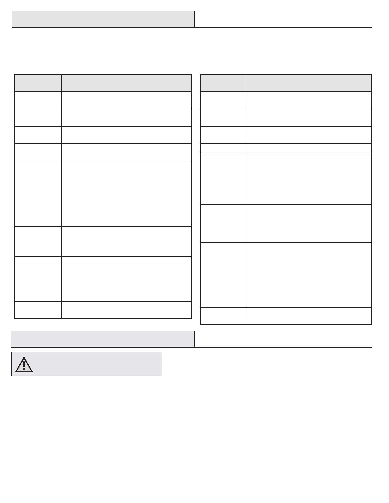
The Greenhaven 60 in. ceiling fan works with Alexa and Google Assistant.
This section lists some of the voice commands you can use. To view these and other commands, go to http://hubspaceconnect.com/.
□ Because of the fan’s natural movement, some connections may become loose. Check the support connections, brackets, and blade
attachments twice a year. Make sure they are secure. It is not necessary to remove the fan from the ceiling.
□ Clean your fan periodically to help maintain its new appearance over the years. Do not use water when cleaning, as this could damage the
motor, or the wood, or possibly cause an electrical shock. Use only a soft brush or lint-free cloth to avoid scratching the nish.
□ You can apply a light coat of furniture polish to the wood for additional protection and enhanced beauty. Cover small scratches with a light
application of shoe polish.
□ You do not need to oil your fan. The motor has permanently-lubricated sealed ball bearings.
WARNING: Make sure the power is off before cleaning
your fan.
Care and Cleaning
18
Troubleshooting
Problem Solution
The fan will not start. □ Check the main and branch circuit fuses or breakers.
□ Check to make sure the wall switch is in the on position if applicable.
□ Check the line wire connections to the fan and switch wire connections in the switch housing.
□ Check the battery in the transmitter.
□ Ensure you are in the normal range of 10-20 feet.
□ Remember to turn off the power supply before checking the dip switches settings.
The fan is noisy. □ Ensure all motor housing screws are snug.
□ Ensure the screws that attach the fan blade bracket to the motor hub are tight.
□ Ensure the wire nut connections are not rattling against each other or the interior wall of the switch housing.
□ Allow a 24-hour “breaking in” period. Most noises associated with a new fan disappear during this time.
□ If you are using the ceiling fan light kit, ensure the screws securing the glassware are tight. Check that the light bulbs
are also secure.
□ Ensure the canopy is a short distance from the ceiling. It should not touch the ceiling.
□ Ensure your outlet box is secure and rubber isolator pads were used between the mounting plate and outlet box.
The fan wobbles. □ Check that all blade and blade arm screws are secure.
□ Most fan wobble problems are caused when blade levels are unequal. Check this level by selecting a point on the
ceiling above the tip of one of the blades. Measure from a point on the center of each blade to the point on the
ceiling. Rotate the fan until the next blade is positioned for measurement. Repeat for each blade. Any measurement
deviation should be within 1/8 inch. Run the fan for ten minutes. If the fan continues to wobble please contact
customer service and a balancing kit will be sent to you at no charge.
The fan moves backwards
and forwards when turned on.
□ This is normal start-up procedure for DC motor fans. The partial movement during start-up is the result of the DC
motor aligning the internal magnetic poles for proper motor operation. This design saves electricity and allows the
fan to operate much quieter than standard AC motor fans.
Hubspace
TM
Troubleshooting
My hubspace device is not
connecting to Wi-Fi.
□ Make sure your device is connected to a power source.
□ Your Internet connection or Wi-Fi network may be down.
My device cannot nd any
Wi-Fi networks.
□ Make sure you have a 2.4GHz capable Wi-Fi network within range of the device you are trying to add.
My device is in a location that
does not have Wi-Fi. Can I
still use it with the Hubspace
app?
Yes:
□ Use the app on a phone with an Internet connection like LTE.
□ The phone must be within Bluetooth range of your Hubspace device.
I cannot nd the QR code. □ Look for it where other stickers are on the product. A copy of the QR code is also included in your device’s
documentation.
The QR code has become
damaged. How do I add the
device?
□ Under the QR code are numbers. You can enter those in manually instead of scanning the code.
How do I reset the device? □ Remove the device from your account, then add it back. Devices also reset when they transfer to a new account.
A device is on another
account. How do I transfer it?
□ Scan the QR code and it will transfer to your account.
My device is ofine for long
periods of time.
□ Make sure your Wi-Fi signal strength is sufcient. You may need to move your router, use mesh Wi-Fi, or Wi-Fi
extenders.
The device is on and I
scanned the QR code, but the
app cannot connect to it.
□ Turn off Bluetooth on your phone and turn it back on. Then, scan the QR code.
Can I scan the same QR code
to add multiple products?
□ No. Each product has a unique QR code.

FCC Statement: This equipment has been tested and found to comply with the limits for a Class B digital device, pursuant to Part 15 of the FCC Rules. These limits are designed to provide
reasonable protection against harmful interference in a residential installation. This equipment generates, uses and can radiate radio frequency energy and, if not installed and used in
accordance with the instructions, may cause harmful interference to radio communications. However, there is no guarantee that interference will not occur in a particular installation. If
this equipment does cause harmful interference to radio or television reception, which can be determined by turning the equipment off and on, the user is encouraged to try to correct
the interference by one or more of the following measures:
□ Reorient or relocate the receiving antenna.
□ Increase the separation between the equipment and receiver.
□ Connect the equipment into an outlet on a circuit different from that to which the receiver is connected.
□ Consult the dealer or an experienced radio/TV technician for help.
CAUTION:
Any changes or modications not expressly approved by the grantee of this device could void the user’s authority to operate the equipment.
This device complies with Part 15 of the FCC Rules. Operation is subject to the following two conditions: (1) This device may not cause harmful interference, and (2) this device must
accept any interference received, including interference that may cause undesired operation.
Questions, problems, missing parts? Before returning to the store,
call Hubspace Customer Service
8 a.m. - 7 p.m., EST, Monday-Friday, 9 a.m. - 6 p.m., EST, Saturday
1-877-592-5233
HOMEDEPOT.COM/HUBSPACE
Retain this manual for future use.
GRACIAS
Apreciamos la plena conanza depositada en Home Decorators Collection al comprar este ventilador de techo. Nos esforzamos en crear
continuamente productos de calidad diseñados para mejoras del hogar. Visítanos por Internet para ver nuestra línea completa de productos
disponibles a n de satisfacer la necesidades de mejoras de tu hogar. ¡Gracias por elegir Home Decorators Collection!
Artículo Núm. 1007 848 685, 1007 848 650
Modelo Núm. 56006, 56042
Modelo Núm. 60-ANUN aprobado por UL
GUÍA DE USO Y MANTENIMIENTO
VENTILADOR DE TECHO GREENHAVEN, DE 152 CM
Para ver un video instructivo sobre cómo instalar este producto:
1. Visita www.homedepot.com e ingresa en el campo de búsqueda el número del modelo o artículo,
que aparece en la esquina superior derecha de la portada de este manual de instrucciones.
2. Haz clic sobre tu producto en la lista de resultados de la búsqueda y sobre el enlace de video en
la sección “Product Overview” [Información general del producto].
¿Preguntas, problemas, piezas faltantes? Antes de regresar a la tienda,
llama al Servicio de atención al cliente de Hubspace
de lunes a viernes, entre 8:00 a.m. a 7:00 p.m. (hora del Este),
y los sábados de 9:00 a.m. a 6:00 p.m. (hora del Este)
1-877-592-5233
HOMEDEPOT.COM/HUBSPACE
2
Tabla de contenido .............................................................. 2
Información de seguridad...................................................2
Garantía ................................................................................3
Preinstalación ......................................................................3
Instalación ............................................................................6
Ensamblaje ...........................................................................7
Funcionamiento .................................................................15
Mantenimiento y limpieza .................................................17
Solución de problemas .....................................................18
1. Para disminuir el riesgo de descarga eléctrica hay que garantizar
el corte de electricidad en el cortacircuitos o en la caja de fusibles
antes de comenzar.
2. Todo el cableado tiene que cumplir con el Código Nacional de
Electricidad ANSI/NFPA 70 y con los códigos eléctricos locales. La
instalación eléctrica debe hacerse por un electricista certicado y
calicado.
3. La caja eléctrica y la estructura de soporte tienen que montarse de
forma segura para poder sostener con conanza y como mínimo 35
lb (15.9 kg). Usa solo cajas eléctricas aprobadas por UL y marcadas
como “Apropiada para sostener ventiladores de 35 lb (15.9 kg) o
menos”.
4. El ventilador debe ir montado a un mínimo de 7 pies (2.1 m) de
separación entre el borde trasero de las aspas y el piso.
5. No coloques objetos en la trayectoria de las aspas.
6. Para evitar lesiones físicas o daños al ventilador y otros artículos,
ten cuidado al limpiarlo o al trabajar cerca de él.
7. Después de concluir las conexiones eléctricas, debes voltear los
conductores empalmados hacia arriba y meterlos con cuidado en
la caja eléctrica. Los cables deben estar separados con el cable
a tierra y el conductor a tierra del equipo a un lado de la caja
eléctrica.
8. Antes de la instalación, todos los tornillos de fijación tienen
que comprobarse y reajustarse donde sea necesario.
ADVERTENCIA: Para reducir el riesgo de lesiones
personales, no dobles los soportes de las aspas
(también llamados “bridas”) durante o después de
la instalación. No colocar objetos en la trayectoria
de las aspas.
ADVERTENCIA: Los diagramas eléctricos son sólo
para referencia. Si usas un kit de luces, consulta
el manual de instrucciones del kit de luces para
hacer las conexiones eléctricas. El uso opcional de
cualquier kit de luces debe estar aprobado por UL y
estar marcado como adecuado para ser usado con
este ventilador.
ADVERTENCIA: Para evitar posible descarga
eléctrica, desconecta la electricidad en la caja
principal de fusibles antes de cablear. En caso de
no tener suciente conocimiento o experiencia
sobre cableado eléctrico, contactar a un electricista
certicado.
Información de seguridad
Tabla de contenido
PRECAUCIÓN: Para reducir el riesgo de lesiones,
usa sólo los tornillos incluidos con la caja eléctrica.
ADVERTENCIA: Para reducir el riesgo de incendio,
descarga eléctrica o lesiones personales, instala
solo en una caja eléctrica clasicada como
“apropiada para sostener ventiladores de 35 lb (15.9
kg) o menos” y usa los tornillos que vienen con ella.
LEE Y GUARDA ESTAS INSTRUCCIONES.
ADVERTENCIA: Para reducir el riesgo de incendio o
descarga eléctrica este ventilador sólo debe usar
la pieza núm. JY1156H-LD-F1-EL de control de
velocidad fabricada por Chungear Industrial Co., Ltd.
ADVERTENCIA: A n de reducir el riesgo de
descargas eléctricas, este ventilador tiene
que instalarse con un interruptor de pared con
aislamiento.
3
HOMEDEPOT.COM/HUBSPACE
Para obtener asistencia, llama al 1-877-592-5233.
Preinstalación
Garantía
ESPECIFICACIONES
NOTA: Estas medidas son aproximadas. No incluyen el
amperaje ni el vataje consumido por el kit de luces.
Tamaño Velocidad Voltios
Consumo de
energía del
ventilador
(sin luces)
VATIOS
Flujo de aire en
pies cúbicos por
minuto (CFM)
Eciencia de
ujo de aire
(Mientras más
alta, mejor)
CFM/W
Peso
neto
Peso
bruto
Pies
cúbicos
60 plg
(152 cm)
Baja
120
4 2142 535
17.64 lb
(8 kg)
23.59 lb
(10.5 kg)
2.19 pies³
(0.06 m³)
Media 11 4287 389
Alta 40 6668 166
HERRAMIENTAS NECESARIAS
Destornillador
Phillips
Destornillador
plano
Llave
ajustable
Cinta de
electricista
Pelacables/
cortacables
Escalera de tijera
El proveedor garantiza de por vida, a partir de la fecha de adquisición por el comprador original, que el motor del ventilador no presenta defectos de
fabricación ni de materiales al momento del envío desde la fábrica. El proveedor garantiza que el kit de luces, excluyendo cualquier vidrio, no tendrá
defectos de fabricación ni de material en el momento del envío desde la fábrica por un período de cinco años después de la fecha de compra por
parte del comprador original. El proveedor también garantiza, por dos años a partir de la fecha de adquisición por el comprador original, que todas
las demás piezas del ventilador, excepto las aspas de vidrio o acrílicas, no presentarán ningún defecto de fabricación ni de material al momento
del envío desde la fábrica. Si el producto es devuelto, aceptamos reparar tales defectos sin cargo alguno o, a nuestra discreción, reemplazarlo
por un modelo similar o superior. Para obtener servicio de garantía tiene que presentar una copia del recibo como comprobante de compra. Todos
los costos de retiro y reinstalación del producto correrán por cuenta del cliente. Los daños a cualquier pieza por accidente, instalación o uso
inadecuado, o por montar cualquier accesorio, no están cubiertos por esta garantía. Puesto que las condiciones climáticas pueden variar, esta
garantía no cubre ningún cambio del acabado en latón, como óxido, perforación, corrosión, manchas o descascaramiento. Este tipo de acabados
en latón tiene una la vida útil prolongada si se lo protege contra las condiciones climáticas cambiantes. Cierta “oscilación” es normal y no debe
considerase un defecto. Cualquier servicio prestado por personal no autorizado invalidará la garantía. No hay ninguna otra garantía expresa. Por
este medio Home Depot Decorators Collection se exime de cualquier garantía, incluyendo pero sin limitarse a, aquellas de comercialización e
idoneidad para determinado propósito en el alcance permitido por la ley. La duración de cualquier garantía implícita que no pueda exonerarse se
limita al plazo especicado en la garantía explícita. Algunos estados no permiten limitaciones sobre la duración de las garantías implícitas, así que
es posible que la limitación anterior no se aplique en su caso. El minorista no será responsable por daños incidentales, emergentes ni especiales
derivados del uso o funcionamiento del producto, excepto en los casos en los que la ley así lo disponga. Algunos estados no permiten excluir ni
limitar daños directos o indirectos, así que es posible que la limitación o exclusión anterior no se aplique en este caso. Esta garantía otorga derechos
legales especiales al cliente y es posible que también goce de otros derechos que pueden variar según el estado. Esta garantía sustituye a todas las
garantías anteriores. Los costos de envío en cualquier devolución de productos como parte de un reclamo de garantía corren por cuenta del cliente.
Comuníquese con el Equipo de Servicio al Cliente al teléfono 1-877-592-5233 o visite www.HomeDepot.com/hubspace.
4
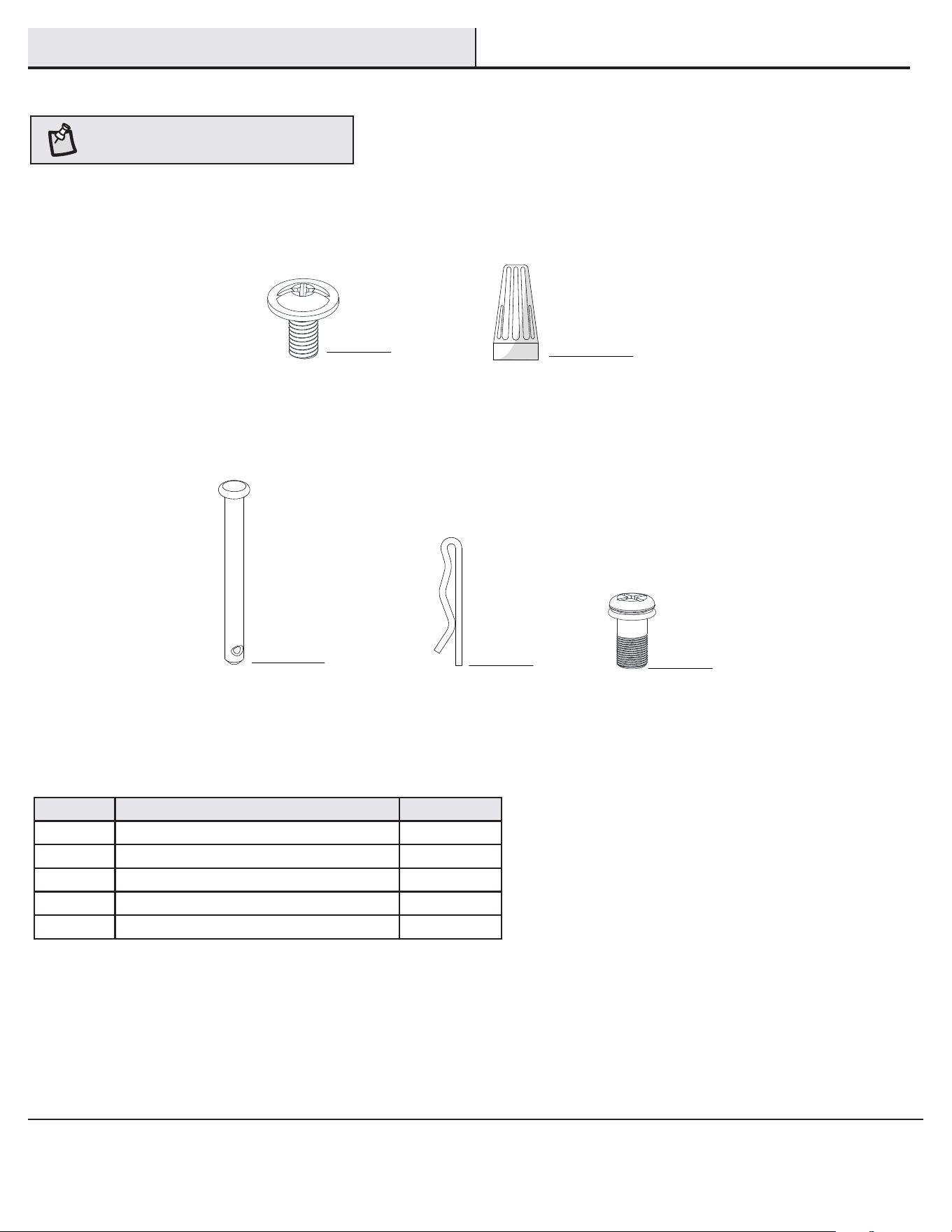
Pieza Descripción Cantidad
AA Tornillos para jar las aspas 16
BB Tuerca de plástico para conectar cables 3
CC Pasador de soporte 1
DD Pasador de cierre 1
EE Tornillo adicional para soporte de aspas 1
Preinstalación (continuación)
HERRAJES INCLUIDOS
NOTA: Los herrajes no se muestran en
tamaño real.
BB
CC
DD
AA
EE
5
HOMEDEPOT.COM/HUBSPACE
Para obtener asistencia, llama al 1-877-592-5233.
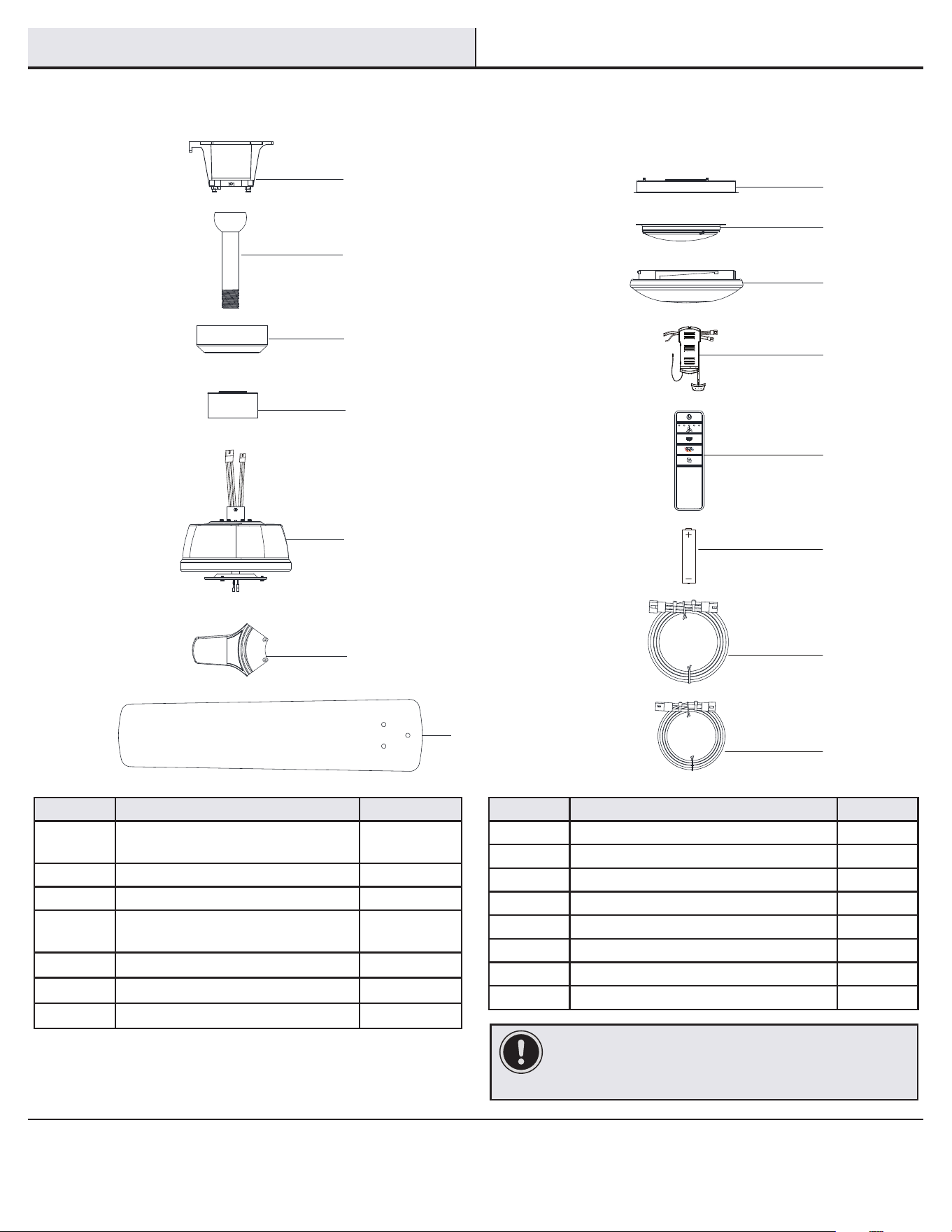
Pieza Descripción Cantidad
A
Soporte de montaje deslizante
(dentro de la cubierta)
1
B Conjunto de tubo bajante/esfera 1
C Cubierta 1
D Cubierta decorativa del collarín del
motor
1
E Ensamblaje del motor del ventilador 1
F Soporte de aspa 5
G Aspa 5
Pieza Descripción Cantidad
H Carcasa del kit de luces 1
I Conjunto del soporte del kit de luces 1
J Pantalla de vidrio 1
K Receptor 1
L Control remoto 1
M Batería 2
N Cable de extensión de 3 clavijas (66 plg = 1.7 m) 1
O Cable de extensión de 2 clavijas (66 plg = 1.7 m) 1
IMPORTANTE: Este producto y/o sus componentes están
protegidos por una o más de las siguientes patentes en EE. UU.:
5,947,436; 5,988,580; 6,010,110; 6,046,416; 6,210,117, así como
otras patentes pendientes.
Preinstalación (continuación)
CONTENIDO DEL PAQUETE
L
M
N
O
H
I
J
K
B
C
D
E
F
G
A
6
Instalación
OPCIONES DE MONTAJE
ADVERTENCIA: Para reducir el riesgo de incendio,
descarga eléctrica o lesiones personales, instala solo
en una caja eléctrica clasicada como “Apropiada para
sostener ventiladores de 35 lb (15.9 kg) o menos” y usa
los tornillos que vienen con ella. Las cajas eléctricas
utilizadas comúnmente para el soporte de lámparas
pueden no servir como soporte de ventilador y tal vez
deban reemplazarse. En caso de duda, consulta a un
electricista calicado.
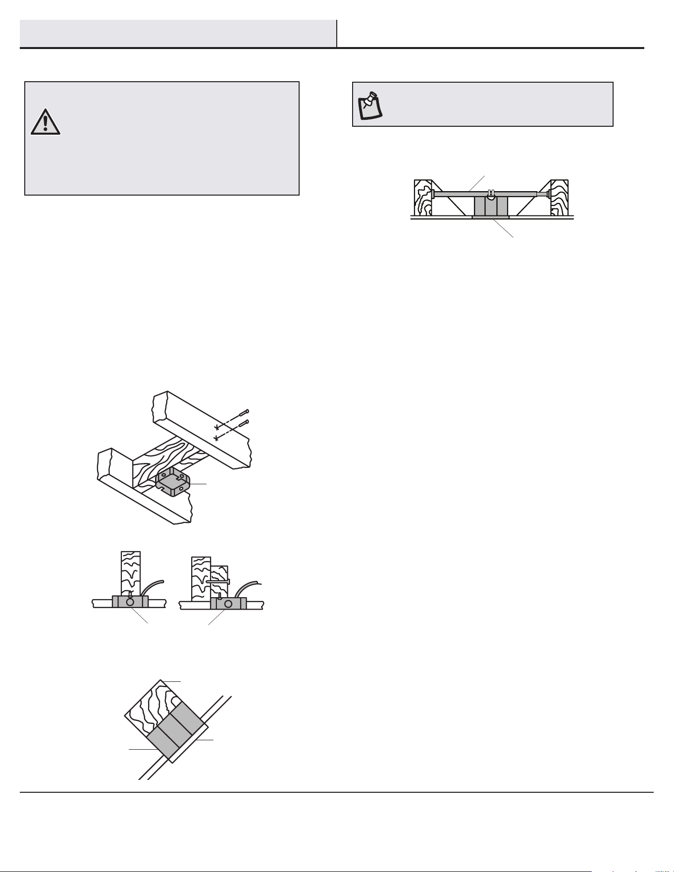
Si tu ventilador de techo no tiene una caja de montaje aprobada
por UL, instálala siguiendo las instrucciones a continuación:
□ Desconecta la energía retirando los fusibles o apagando los
cortacircuitos.
□ Asegura la caja eléctrica directamente a la estructura de
la edicación. Usa sujetadores y materiales apropiados. La
caja eléctrica y la estructura de soporte tienen que montarse
de forma segura para poder sostener con conanza y como
mínimo 35 lb (15.9 kg). Usa solo cajas eléctricas aprobadas
por UL y marcadas como “Apropiada para sostener
ventiladores de 35 lb (15.9 kg) o menos” No usar una caja
eléctrica de plástico.
Las ilustraciones a continuación muestran tres formas distintas
de montar la caja eléctrica.
Si la cubierta (C) toca el conjunto del tubo bajante/esfera (B), retira la
tapa inferior decorativa del collarín del motor (D) y gira 180º la cubierta
(C) antes de jarla (C) a la placa de montaje.
Para colgar el ventilador donde hay una lámpara, pero ninguna viga de
techo, tal vez se necesite una barra para colgar como se muestra más
arriba (disponible en cualquier tienda de The Home Depot).
NOTA: Tal vez necesites un tubo bajante más largo para
mantener la altura mínima adecuada de las aspas, al
instalar el ventilador en un techo inclinado. El ángulo
máximo permitido es 15º desde la horizontal.
Caja
eléctrica
Caja eléctrica
Caja
eléctrica
empotrada
Provee un
soporte fuerte
Placa de
montaje
en techo
Caja eléctrica
Barra para colgar
7
HOMEDEPOT.COM/HUBSPACE
Para obtener asistencia, llama al 1-877-592-5233.
Ensamblaje - Montaje estándar en techo
Cómo tender los cables
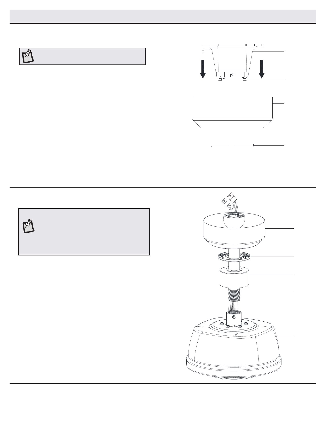
Preparación para el montaje
□ Retira la tapa inferior magnética (JJ) de la cubierta (C),
tirando de ella hasta soltarla.
□ Aoja los dos tornillos de la cubierta (FF) ubicados en el
soporte deslizante de montaje (A).
□ Gira el soporte de montaje deslizante (A) hacia la izquierda y
levántalo para retirarlo de la cubierta (C).
□ Inserta los cables que salen por la parte superior del ensamblaje
del motor de ventilador (E) a través de la cubierta decorativa del
collarín del motor (D) y enseguida a través del centro de la tapa
inferior de la cubierta (JJ).
□ Asegúrate de que la abertura de la cubierta (C) esté sobre la
parte superior e inserta el conjunto del tubo bajante/esfera (B) a
través de la cubierta (C).
□ Inserta los cables que salen por la parte superior del ensamblaje
motor-ventilador (E) a través del tubo bajante, como se muestra.
2
1
NOTA: El ventilador viene con cables terminales de 12
plg (30.5 cm) para usar con el conjunto de tubo bajante/
esfera (B) de 6 plg (15.2 cm) incluido. Si deseas usar un
tubo bajante más largo, conecta el cable de extensión de
3 clavijas (N) y el cable de extensión de 2 clavijas (O) al
ventilador conectando los enchufes del adaptador moldeado
de los cables de extensión a los enchufes del adaptador de
3 clavijas y 2 clavijas del ventilador.
NOTA: El imán viene prejado en la tapa inferior de la
cubierta para quitar e instalar fácilmente.
C
D
E
JJ
B
FF
C
A
JJ
8
Cómo jar el ventilador a la
caja eléctrica
□ Aoja los dos tornillos de montaje (GG) de la caja eléctrica.
□ Pasa los cables de suministro de 120 V a través del oricio
central en el soporte de montaje deslizante (A).
□ Desliza el soporte de montaje deslizante (A) en los tornillos de
montaje (GG) y centra el soporte de montaje deslizante (A) en
relación con la caja eléctrica. Si es necesario, usa arandelas
niveladoras (no se incluyen) entre el soporte de montaje
deslizante (A) y la caja eléctrica. El lado plano del soporte de
montaje deslizante (A) debe mirar hacia la caja eléctrica, como
se muestra.
□ Ajusta rmemente los dos tornillos de montaje (GG).
1
ADVERTENCIA: Para reducir el riesgo de incendio,
descarga eléctrica o lesiones personales, instala solo
en una caja eléctrica clasicada como “apropiada para
sostener ventiladores de 35 lb (15.9 kg) o menos” y
usa los tornillos que vienen con ella.
NOTA: El soporte de montaje deslizante (A) está
diseñado para ser colocado sobre una caja eléctrica
con los tornillos de esta (GG) instalados.
Ensamblaje - Montaje estándar en techo (continuación)
Cómo ensamblar el ventilador
□ Aoja, sin quitarlos, los tornillos de jación (KK) del collarín (PP) ubicado en la
parte superior del ensamblaje del motor del ventilador (E).
□ Instala el conjunto del tubo bajante/esfera (B) insertándolo en el collarín del
motor (PP) y girándolo hacia la derecha hasta que los oricios en la parte
inferior del conjunto del tubo bajante/esfera (B) queden alineados con los
oricios en el collarín de la parte superior del ensamblaje motor-ventilador (E).
□ Inserta con cuidado el pasador de soporte (CC) a través de los oricios del
collarín (KK) y del conjunto del tubo bajante/esfera (B). Ten cuidado de no
forzar el pasador de soporte (CC) contra el cableado dentro del conjunto del
tubo bajante/esfera (B).
□ Inserta el pasador de cierre (DD) en el oricio cercano al extremo del pasador
de soporte (CC) hasta que encaje en su posición.
□ Vuelve a apretar los tornillos de jación (KK) del collarín (PP) en la parte
superior del ensamblaje del motor y el ventilador (E).
ADVERTENCIA: Si el pasador de cierre no se instala
correctamente (DD), es posible que el ventilador se
aoje y caiga.
PRECAUCIÓN: Para asegurarte de que no haya oscilación
y evitar dañar el ventilador, el conjunto del tubo bajante/
esfera (B) y el tornillo del jación (KK) tienen que estar
completamente ajustados.
3
Ensamblaje - Cómo colgar el ventilador
C
D
E
JJ
B
CC
DD
KK
PP
A
GG
GG
9
HOMEDEPOT.COM/HUBSPACE
Para obtener asistencia, llama al 1-877-592-5233.
Ensamblaje - Cómo colgar el ventilador (continuación)
Cómo colgar el ventilador
□ Levanta con cuidado el conjunto motor-ventilador (E) hasta
el soporte de montaje deslizante (A).
□ Inserta la bola del conjunto del tubo bajante/esfera (B) en
el casquillo del soporte de montaje deslizante (A).
□ Gira el conjunto de tubo bajante/esfera (B) hacia la
derecha hasta que quede encajado con la pestaña del
soporte de montaje deslizante (A) alineada con la ranura
de la esfera.
2
B
A
E
Cómo instalar el receptor
□ Ubica los cables de suministro doméstico en un lado
del soporte de montaje deslizante (A). Coloca los
cables del ventilador en el lado opuesto.
□ Inserta el extremo angosto del receptor (K) (como
se muestra, con el lado plano hacia el techo) en
el soporte de montaje deslizante (A) hasta dejarlo
apoyado en la parte superior del conjunto tubo
bajante/esfera (B).
3
ADVERTENCIA: Para reducir el riesgo de incendio
o descarga eléctrica, recuerda desconectar la
electricidad. El cableado eléctrico tiene que cumplir
todos los requisitos de los códigos eléctricos
nacionales y locales. La fuente de energía y el
ventilador tienen que ser de 110/120 V y 60 Hz. No
utilizar este producto con ningún control variable de
pared. Conectar el cableado de manera incorrecta
dañará este receptor.
PRECAUCIÓN: Si otros cables del ventilador son de color
diferente, un electricista certicado deberá instalar esta
unidad.
A
K
B
10
Ensamblaje - Cómo colgar el ventilador (continuación)
Cómo cablear el ventilador al receptor
5
□ Si usas el conjunto del tubo bajante/esfera (B) de 6 plg
(15.2 cm) incluido, conecta los cables del receptor a los cables
del ventilador uniendo el enchufe del adaptador moldeado del
receptor (K) con el adaptador moldeado del ensamblaje del
motor del ventilador (E).
□ Si deseas un tubo bajante más largo, puedes usar la
extensión de cable terminal (66 plg = 1.7 m) (O) y (N) incluida
conectando el adaptador moldeado.
Cómo cablear el receptor al
cableado del hogar
4
ADVERTENCIA: Para evitar posible descarga eléctrica,
desconecta la electricidad en la caja principal de
fusibles antes de cablear. Si crees que no tienes
suciente conocimiento o experiencia sobre cableado
eléctrico, contacta a un electricista certicado.
ADVERTENCIA: Cada tuerca para cable suministrada
con este ventilador está diseñada para aceptar un
cable doméstico de calibre 12 o menos y dos cables del
ventilador. Si tu cableado doméstico tiene calibre mayor
de 12 o más de un cable para conectar al cableado
del ventilador, consulta a un electricista para saber el
tamaño adecuado de las tuercas a usar para los cables.
IMPORTANTE: Usa las tuercas de conexión de
cables (BB) que vienen con tu ventilador. Sujeta los
conectores con cinta de electricista y asegúrate de
que no haya conexiones ni cables sueltos.
□ Separa los cables de manera que los cables verde y blanco queden
de un lado de la caja eléctrica y el cable negro, del otro lado.
□ Conecta los cables verdes del ventilador al cable con conexión a
tierra de la casa (este puede ser verde o pelado) con una tuerca de
conexión de cables (BB).
□ Conecta el cable negro (o rojo) del receptor (K) al cable negro
(positivo) del hogar, usando una tuerca de conexión de cables (BB).
□ Conecta el cable blanco del receptor (K) al cable blanco del hogar
(neutro) con una tuerca de conexión de cables (BB).
□ Asegura cada tuerca de conexión de cables con cinta de electricista.
NOTA: El ventilador viene con cables terminales de 12
plg (30.5 cm) para usar con el conjunto de tubo bajante/
esfera (B) de 6 plg (15.2 cm) incluido. Si deseas usar un
tubo bajante más largo, conecta el cable de extensión
de 3 clavijas (N) y el cable de extensión de 2 clavijas
(O) al ventilador conectando los enchufes del adaptador
moldeado de los cables de extensión a los enchufes del
adaptador de 3 clavijas y 2 clavijas del ventilador.
N
O
Caja eléctrica
Verde
Negro
Negro
Verde (o pelado)
Verde
Caja
eléctrica
Antena
receptora
Blanco
K
BB
Verde
Antena
Wi-Fi
11
HOMEDEPOT.COM/HUBSPACE
Para obtener asistencia, llama al 1-877-592-5233.
Ensamblaje - Cómo colgar el ventilador (continuación)
Montaje del conjunto del motor
del ventilador (montaje estándar)
6
ADVERTENCIA: Cuando uses el montaje del tubo
bajante/esfera estándar, la pestaña en el aro en la
parte inferior del soporte de montaje deslizante (A)
tiene que encajar en la ranura de la bola de soporte. Si
la pestaña no se asienta correctamente en la ranura,
se puede dañar el cableado.
NOTA: El imán viene prejado en la tapa inferior de la
cubierta para quitar e instalar fácilmente.
□ Alinea las ranuras de cierre de la cubierta (C) con los dos
tornillos (FF) y el poste de alineación (QQ) del soporte de
montaje deslizante (A).
□ Empuja hacia arriba la cubierta (C) y gírala hacia la derecha
hasta que el poste de alineación (QQ) se enganche en el oricio
redondo y los tornillos (FF), en las ranuras tipo ojo de cerradura.
□ Aprieta rmemente los dos tornillos de montaje (FF).
□ Alinea la forma oval sobre la cubierta (C) con su tapa protectora
inferior (JJ).
□ Empuja hacia arriba la tapa inferior de la cubierta (JJ) hasta que
las cabezas de los tornillos (FF) se enganchen con las ranuras
de la tapa magnética (JJ) de manera que esta quede bien jada
a la parte inferior de la cubierta (C).
NOTA: Para mejor rendimiento con el sistema WI-Fi, la
antena WI-Fi tiene que montarse en el cielo raso fuera de
la cubierta del ventilador de techo.
QQ
A
B
E
C
JJ
FF
Vista después de la instalación
Antena Wi-Fi montada
fuera de la cubierta
D
12
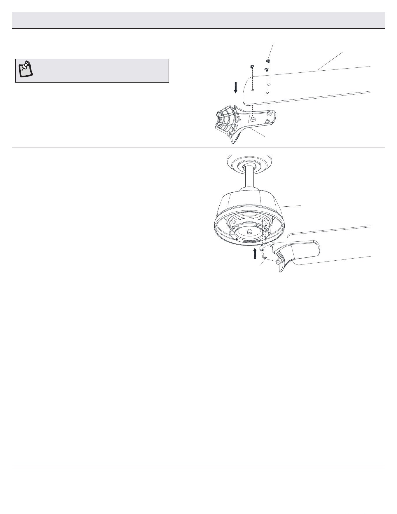
Ensamblaje - Cómo jar las aspas del ventilador
Cómo jar las aspas del ventilador
a los soportes de las aspas
1
□ Monta un aspa (G) en su soporte (F) colocando los tornillos de
jación del aspa (AA) en los oricios del aspa (G) y a través
del soporte de esta (F).
□ Aprieta rmemente todos los tornillos.
□ Repite este paso para cada aspa y soporte.
NOTA: Las aspas de tu ventilador son reversibles. Elige
el acabado del aspa por el lado que mejor resalte tu
decoración.
Cómo jar los ensamblajes de las
aspas al motor
2
□ Fija el conjunto del aspa y su soporte al ensamblaje motor-
ventilador (E) insertando los postes de alineación dentro de la
ranura de la parte inferior del motor y aprieta los tornillos del
soporte del aspa (EE) preinstalados.
□ Repite estos pasos para ensamblar las aspas restantes.
AA
G
F
EE
E
13
HOMEDEPOT.COM/HUBSPACE
Para obtener asistencia, llama al 1-877-592-5233.
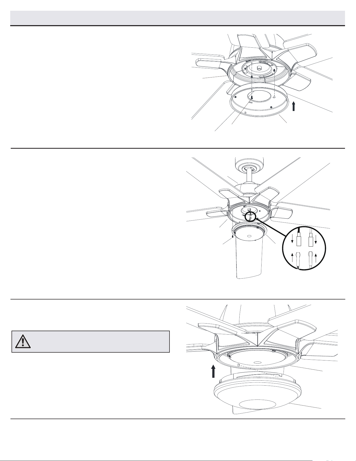
Cómo instalar el conjunto del soporte
del kit de luces
2
□ Quita un tornillo (TT) de la carcasa del kit de luces (H) y aoja
los otros dos tornillos, pero sin quitarlos.
□ Conecta los cables del conjunto del soporte del kit de luces (I)
a los cables del ensamblaje motor-ventilador (E), conectando
juntos los enchufes del adaptador moldeado. Coloca con
cuidado todos los cables y empalmes dentro de la caja del
interruptor.
□ Empuja el conjunto del soporte del kit de luces (I) hacia la
carcasa del kit (H) de manera que los dos tornillos aojados
encajen en las ranuras tipo ojo de cerradura. Gira el conjunto
del soporte del kit de luces (I) en el sentido de las manecillas
del reloj para asegurarlo.
□ Vuelve a instalar el tornillo retirado en el primer paso.
□ Comprueba que todos los tornillos estén rmemente
apretados.
Cómo instalar la pantalla de vidrio
3
□ Coloca la pantalla de vidrio (J) en la carcasa del kit de luces
(H), alineando las tres áreas planas en el reborde superior de
la pantalla de vidrio (J) con las tres muescas salientes de la
carcasa del kit de luces (H). Gira la pantalla hacia la derecha
hasta que se detenga.
ADVERTENCIA: No aprietes demasiado al instalar la pantalla de
vidrio en el kit de luces. Espera que la pantalla de vidrio se enfríe
completamente antes de retirarla.
Cómo instalar la carcasa del kit de luces
1
□ Quita un tornillo (OO) del soporte negro bajo el ensamblaje
motor-ventilador (E) y aoja los otros dos, pero sin quitarlos.
□ Empuja la carcasa del kit de luces (H) hacia el ensamblaje
motor-ventilador (E) de manera que los dos tornillos aojados
encajen en los oricios tipo ojo de cerradura. Gira la carcasa
del kit de luces (H) hacia la derecha.
□ Vuelve a instalar el tornillo (OO) retirado en el primer paso.
□ Comprueba que todos los tornillos estén rmemente
apretados.
Ensamblaje - Cómo instalar el kit de luces
H
E
OO
J
H
I
TT
H
E
14
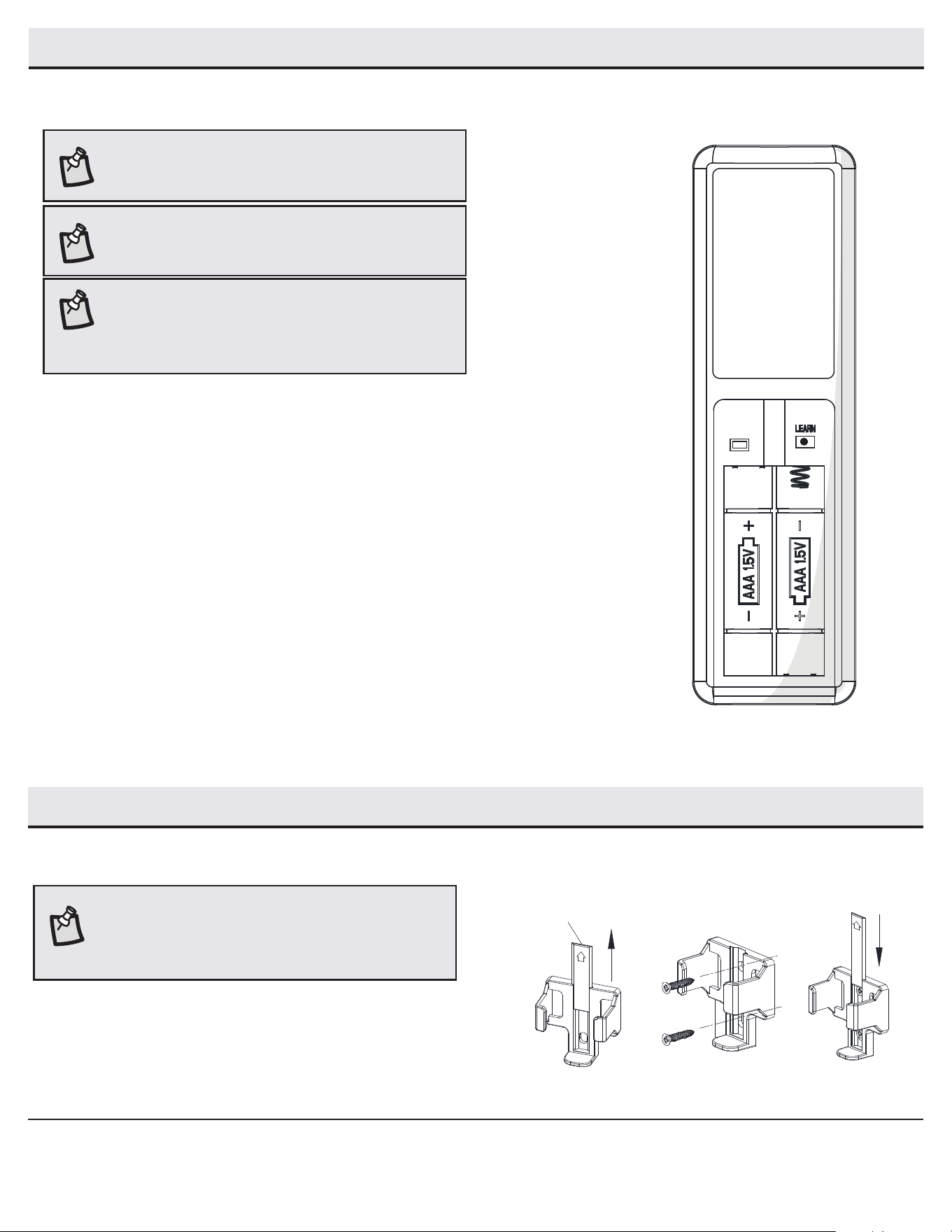
Ensamblaje — Cómo montar los accesorios
Montaje del soporte del control remoto
□ Desliza la placa de la cubierta de los tornillos hacia arriba
para quitarla del soporte de pared.
□ Coloca el soporte de pared en la posición deseada y fíjalo a la
pared con los tornillos del soporte de pared incluidos.
□ Desliza la placa de la cubierta de los tornillos nuevamente
sobre el soporte de pared para ocultar los tornillos.
Placa de cubierta de los tornillos
NOTA: Se incluyen anclajes de pared con tornillos para
soporte adicional. Los tornillos incluidos están diseñados para
atornillarse fácilmente en la pared. Si deseas una sujeción más
permanente o segura, instala los anclajes de pared antes de
jar el soporte de pared a la pared.
Cómo preparar el control remoto
□ Conrma que la electricidad del ventilador está cortada en el interruptor de pared o en la caja del cortacircuitos.
□ Quita la cubierta de la batería presionando con rmeza sobre la echa y deslizando la cubierta hasta liberarla.
□ Instalar dos baterías AAA de 1.5 V (M).
□ Conecta la electricidad al ventilador usando el interruptor de pared o la caja del cortacircuitos.
□ Si el control remoto no funciona normalmente, presiona y luego suelta el botón “Learn" durante 1-2 segundos,
ubicado en el compartimiento de la batería del control remoto, dentro de los 30 segundos posteriores al encendido.
□ Si la conguración es exitosa, el kit de luces del ventilador parpadeará y las aspas comenzarán a girar.
□ Coloca de nuevo la cubierta en el control remoto.
Modo 1 a 3
□ Para usar más de un control remoto para tu ventilador, presiona el botón “Learn" durante 10 segundos
y suéltalo a los 30 segundos de encender la electricidad. Si la conguración es exitosa, el kit de luces
del ventilador parpadeará y las aspas comenzarán a girar.
□ Repite el proceso anterior para los controles remotos que deseas que funcionen con este ventilador.
□ El ventilador solo se puede controlar con un máximo de 3 controles remotos al mismo tiempo después
del usar el botón “Learn”. Si utilizas un cuarto de control remoto para manejar el ventilador, el primer
control remoto será reemplazado.
Modo 1 a 1
□ Para usar solo un control remoto para tu ventilador, presiona y suelta el botón “Learn" durante 1-2 segundos
a los 30 segundos de encender la electricidad.. El modo “1 a 3” se borrará y volverá al modo “1 a 1”
NOTA: El control remoto ya ha sido congurado con el ventilador
de techo para tu conveniencia. Si tienes dos ventiladores del
mismo modelo en tu hogar, sigue los pasos de abajo para controlar
cada ventilador por separado.
NOTA: La batería del control remoto se debilitará con el tiempo y
deberá ser reemplazada antes de que se produzca alguna fuga,
ya que esto dañará el control remoto. Mantén la batería fuera del
alcance de los niños y deséchala adecuadamente tras agotarse.
NOTA: El interruptor marcado con “D/O” controla la función de
regulación de la intensidad de las luces. Si deseas utilizar la
función de regulación de intensidad o la aplicación Hubspace,
mantén el interruptor en la posición "D". Para inhabilitar la
función de regulación de intensidad, coloca el interruptor en la
posición "O".
D O
Ensamblaje - Cómo preparar el control remoto
15
HOMEDEPOT.COM/HUBSPACE
Para obtener asistencia, llama al 1-877-592-5233.
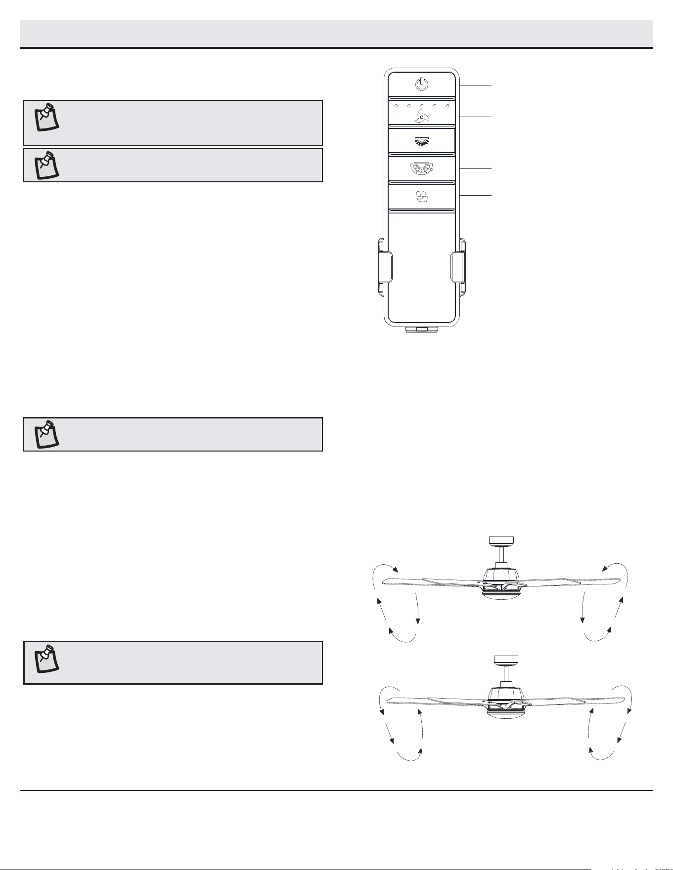
Cómo usar tu ventilador y control remoto
ENCENDIDO/APAGADO:
Presiona y suelta el botón para encender o apagar el ventilador y la luz.
ENCENDIDO/APAGADO/REGULACIÓN DE LA INTENSIDAD DE LA LUZ
Presiona y suelta el botón para encender o apagar la luz.
Presiona y mantén presionado el botón para activar la función de
regulación de intensidad luminosa.
CÓMO CAMBIAR LA TEMPERATURA DE COLOR CORRELACIONADA (CCT)
Presiona y suelta el botón para pasar por las tres opciones de color
según la temperatura.
Opción 1: 2700K (Blanca cálida)
Opción 2: 3000K (Blanca suave)
Opción 3: 3500 K (Blanco neutro).
Opción 4: 4000/4100K (Blanco frío)
Opción 5: 5000K (Luz natural).
Opción 6: 6500K (Luz natural Deluxe).
NOTA: La temperatura congurada por defecto de la luz del
ventilador de techo es de 3000K (Blanca Suave).
Encendido
(ventilador y luz encendido/apagado)
Encendido/apagado/regulación
de la intensidad de la luz
Velocidad del ventilador
Cambiar CCT
Reversa del ventilador
VELOCIDAD DEL VENTILADOR
Las luces LED en el botón de velocidad del ventilador indicarán la
velocidad correspondiente.
Presionar y soltar 1 vez: convierte la velocidad del ventilador a 5.
Presionar y soltar 2 veces: convierte la velocidad del ventilador a 4.
Presionar y soltar 3 veces: convierte la velocidad del ventilador a 3.
Presionar y soltar 4 veces: convierte la velocidad del ventilador a 2.
Presionar y soltar 5 veces: convierte la velocidad del ventilador a 1.
Presionar y soltar 6 veces: para apagar el ventilador.
NOTA: El receptor remoto incluye una función de memoria que
devolverá el ventilador a su última conguración cuando se
enciende mediante el botón de encendido.
REVERSA DEL VENTILADOR
Presiona y suelta el botón de reversa para invertir la rotación del
ventilador de techo.
Clima cálido: (Hacia adelante) Un ujo de aire descendente surte un efecto
refrescante. Esto permite jar tu aire acondicionado en conguración
más alta sin afectar tu comodidad.
Clima frío: (Reversa) Un ujo de aire hacia arriba desplaza el aire cálido
lejos del techo. Esto te permite jar la unidad de calefacción en una
conguración más baja sin afectar tu comodidad.
NOTA: No esperes a que el ventilador se detenga antes de
presionar el botón de reversa. Si el ventilador no está en
movimiento, no cambiará de dirección.
Clima cálido
Clima frío
NOTA: Al comenzar, tu ventilador de techo oscilará hacia
adelante y hacia atrás. Esto es un FUNCIONAMIENTO NORMAL
en ventiladores de techo de CC, ya que realiza un ciclo de
calibración. El ventilador NO ESTÁ DEFECTUOSO.
16
Conguración de la aplicación
NOTA: Para obtener más información sobre la conguración del
control remoto inteligente, consulta la guía de inicio rápido que
se encuentra en el paquete del control remoto.
NOTA: Para usar Alexa para cambiar la temperatura del color de la
luz, asegúrate de que la luz esté encendida primero.
¿Preguntas, problemas o piezas faltantes?
Llama al Servicio al Cliente de Hubspace entre 8:00 a. m. y 7:00 p. m. (hora del Este)
de lunes a viernes, y los sábados de 9:00 a. m. a 6:00 p. m. (hora del Este).
(877) 592-5233
□ Descarga gratis la aplicación gratuita Hubspace™ en la tienda de apps de Apple o Google Play a tu dispositivo móvil.
□ Inicia la aplicación.
□ Para registrarte, ingresa tu dirección de correo electrónico y una contraseña. O inicia sesión si ya tienes una cuenta.
□ Se requiere acceso a Bluetooth para congurar el dispositivo.
Comencemos
1
□ Hubspace solo muestra las redes Wi-Fi que su dispositivo puede usar. Verica tu red solo si una opción no aparece durante la conguración.
□ Este dispositivo Hubspace requiere un canal Wi-Fi de 2.4 GHz.
□ La mayoría de los routers proporcionan un canal Wi-Fi de 2.4 GHz.
□ Si no ves el nombre de tu red Wi-Fi cuando intentes conectar tu dispositivo, verica la conguración de tu router.
Verica tu red
2
□ En la aplicación Hubspace, toca el signo “más” (+) en la esquina superior derecha.
□ Escanea el código QR de tu producto. Puedes encontrar el código QR en el receptor remoto,
dentro de la tapa del compartimento de la batería del control remoto y en el papel de la Guía de
inicio rápido que se incluye con el ventilador.
Añade un dispositivo
3
Si no puedes acceder al código QR de tu luz, puedes ponerlo en modo de descubrimiento con la siguiente secuencia:
□ Apaga y enciende el dispositivo 5 veces. La luz parpadeará para mostrar que ahora se puede descubrir.
□ En la aplicación Hubspace, toca el signo “más” (+) en la esquina superior derecha y sigue las instrucciones para descubrir los dispositivos.
Se puede agregar más de un dispositivo a la vez usando este método.
Congura tu asistente de voz
4
□ En la aplicación Hubspace, toca el botón Hubspace.
□ Selecciona la pestaña Integrations (Integraciones), elige tu asistente de voz y sigue las instrucciones.
Problemas de conexión al dispositivo Hubspace, consulta “Solución de Problemas” en la página 18.
¿Problema de escaneo?
Si el código QR no se puede escanear por alguna razón, puedes ingresar el código manualmente. Toca Ingresar código y sigue las
instrucciones.
□ Conecta tu dispositivo a la corriente y sigue las instrucciones en la pantalla.
(Solo para productos de iluminación y ventiladores)
D O
17
HOMEDEPOT.COM/HUBSPACE
Para obtener asistencia, llama al 1-877-592-5233.
Comandos de voz
Cuando
quieras…
Pídele a Alexa…
Encender solo el
ventilador.
... enciende el ventilador <nombre del dispositivo>.
Apagar solo el
ventilador.
... apaga el ventilador <nombre del dispositivo>.
Encender sola
la luz.
... enciende la luz de <nombre del dispositivo>.
Apagar solo la
luz.
... apaga la luz de <nombre del dispositivo>.
Cambiar la
luminosidad.
… Congura la intensidad luminosa de
<nombre del dispositivo> al 75%.
… Congura la luz de <nombre del dispositivo> al 25%.
… Reduce la intensidad de luz de <nombre del dispositivo>.
… Aumenta la intensidad de luz de <nombre del dispositivo>.
… Reduce la intensidad de luz de <nombre del dispositivo>.
… Aumenta la intensidad de luz de <nombre del dispositivo>.
… Reduce la intensidad de luz de <nombre del grupo>.
… Aumenta la intensidad de luz de <nombre del grupo>.
Cambiar la
temperatura de
color.
… Cambia <nombre del dispositivo> a blanca fría.
… Cambia <nombre del dispositivo> a blanca cálida.
… Cambia <nombre del dispositivo> a luz natural blanca.
… Cambia <nombre del dispositivo> a blanca.
Cambiar la
velocidad del
ventilador.
…
Congura la velocidad de <nombre del dispositivo> a la más rápida.
… Congura la velocidad de <nombre del dispositivo> a rápida.
… Congura la velocidad de <nombre del dispositivo> a media.
… Congura la velocidad de <nombre del dispositivo> a baja.
… Aumenta la velocidad de <nombre del dispositivo>.
… Disminuye la velocidad de <nombre del dispositivo>.
Encender
Comfort Breeze.
… Enciende Comfort Breeze en <nombre del dispositivo>.
Alexa
Cuando
quieras…
Pídele a Google...
Encender solo el
ventilador.
... enciende el ventilador <nombre del dispositivo>.
Apagar solo el
ventilador.
... apaga el ventilador <nombre del dispositivo>.
Encender sola
la luz.
... enciende la luz de <nombre del dispositivo>.
Apagar solo la luz.
... apaga la luz de <nombre del dispositivo>.
Cambiar la
luminosidad.
… Congura la intensidad luminosa de
<nombre del dispositivo> al 75%.
… Congura la luz de <nombre del dispositivo> al 25%.
… Aumenta la intensidad de luz de <nombre del dispositivo>.
… Reduce la intensidad de luz de <nombre del dispositivo>.
… Aumenta la intensidad de luz de <nombre de habitación>.
… Reduce la intensidad de luz de <nombre de habitación>.
Cambiar la
temperatura de
color.
… Cambia <nombre del dispositivo> a marl.
… Cambia <nombre del dispositivo> a luz natural blanca.
… Cambia <nombre del dispositivo> a blanca fría.
… Cambia <nombre del dispositivo> a blanca cálida.
… Cambia <nombre del dispositivo> a incandescente.
Cambiar la
velocidad del
ventilador.
… Congura la velocidad de
<nombre del dispositivo> a la más rápida.
… Congura la velocidad de
<nombre del dispositivo> a rápida.
… Congura la velocidad de
<nombre del dispositivo> a media.
… Congura la velocidad de <nombre del dispositivo> a baja.
… Aumenta la velocidad de <nombre del dispositivo>.
… Disminuye la velocidad de <nombre del dispositivo>.
Encender
Comfort Breeze.
… Enciende Comfort Breeze en <nombre del dispositivo>.
Google
El ventilador de techo Greenhaven de 60 plg (152 cm) funciona con Alexa y el Asistente de Google.
Esta sección enumera algunos de los comandos de voz que puedes utilizar. Para ver estos y otros comandos, visita http: //hubspaceconnect.com/.
□ Debido al movimiento natural del ventilador, algunas conexiones pueden aojarse. Revisa dos veces al año las conexiones de soporte, los
soportes y los accesorios de las aspas. Comprueba que estén seguros. No es necesario desmontar el ventilador del techo.
□ Hay que limpiar el ventilador con frecuencia para que luzca como nuevo al paso de los años. No usar agua para limpiarlo. Esto puede dañar el
motor o la madera e incluso provocar una descarga eléctrica. Usa sólo un cepillo suave o un paño sin pelusas para evitar arañar el acabado.
□ Puedes aplicar a la madera una na capa de pulimento para muebles y dar así más protección y belleza. Cubre los rayones diminutos con una
ligera aplicación de lustrador para calzado.
□ No necesitas lubricar tu ventilador. El motor tiene cojinetes de bola sellados y permanentemente lubricados.
ADVERTENCIA: Asegura que la fuente de corriente está
apagada antes de limpiar el ventilador.
Mantenimiento y limpieza
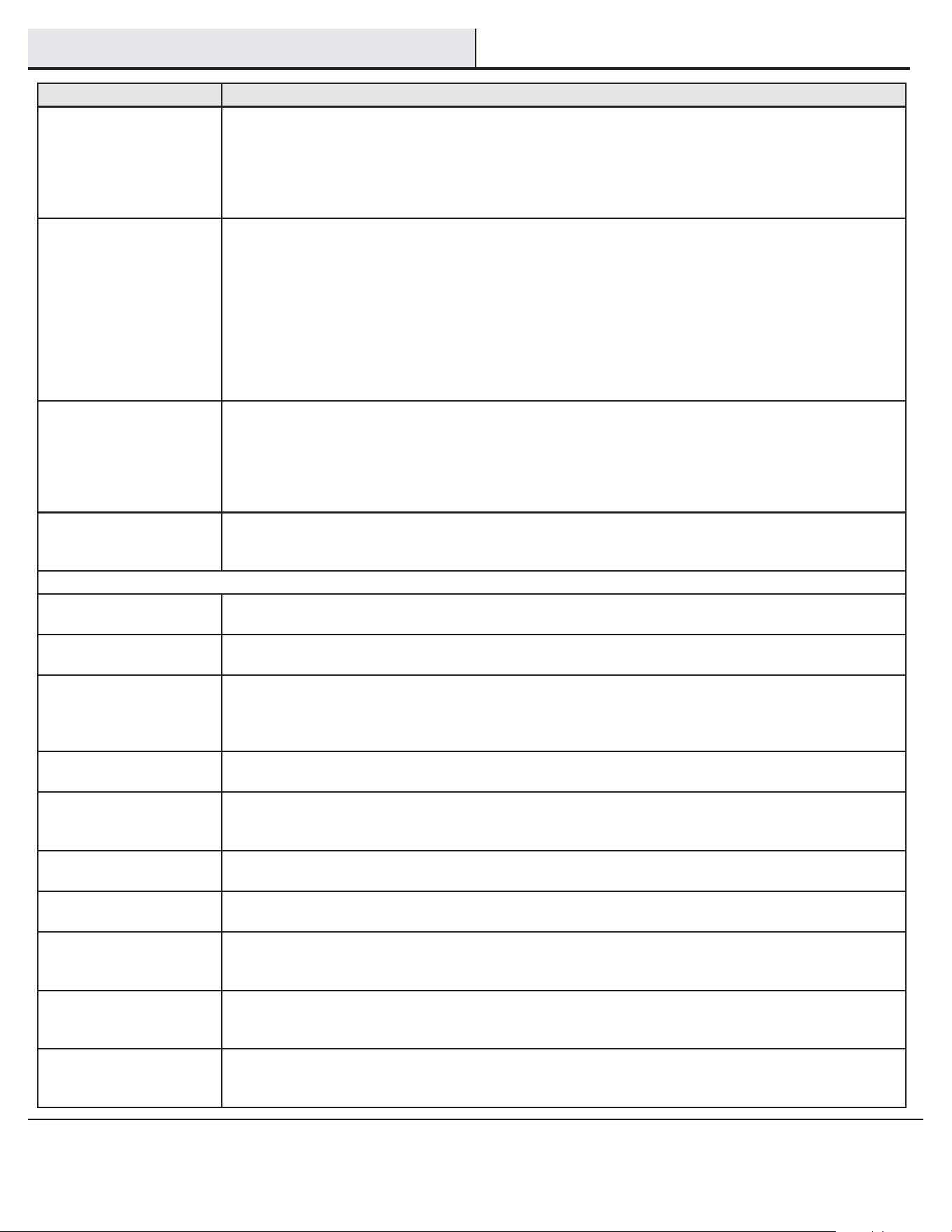
18
Solución de problemas
Problema Solución
El ventilador no enciende. □ Verica los fusibles o cortacircuitos principales y secundarios.
□ Asegúrate de que el interruptor de pared esté en posición de encendido (ON), si corresponde.
□ Verica las conexiones de los cables al ventilador y las conexiones a la caja del interruptor.
□ Revisa la batería del transmisor.
□ Asegúrate de que estén en el rango normal de 10 a 20 pies (3 a 6 metros).
□ Recuerda desconectar la electricidad antes de vericar las conguraciones de los interruptores en línea.
El ventilador hace ruido. □ Asegúrate de que todos los tornillos de la carcasa del motor estén ajustados.
□ Verica que los tornillos que unen el soporte de aspa al cubo del motor estén bien apretados.
□ Asegura que las conexiones de tuerca de cable no choquen unas con otras ni con la pared interior de la caja del interruptor.
□ Deja que transcurra un período de “adaptación” de 24 horas. La mayoría de los ruidos asociados con un ventilador nuevo desapa-
recen en ese período.
□ Si usas el kit de luces de ventilador de techo, asegura que los tornillos que sujetan el vidrio estén bien ajustados. Verica que las
bombillas estén bien apretadas.
□ Controla que la cubierta quede a corta distancia del techo. No debe tocar el techo.
□ Asegúrate de que la caja eléctrica quede bien ajustada y se hayan instalado almohadillas aislantes de goma entre la placa de
montaje y la caja eléctrica.
El ventilador oscila. □ Verica que todas las aspas y los tornillos de sus brazos estén bien ajustados.
□ La mayoría de los problemas de oscilación del ventilador se debe a que las aspas no están al mismo nivel. Verica este nivel
seleccionando un punto en el techo sobre la punta de una de las aspas. Mide desde un punto en el centro de cada aspa al punto en
el techo. Gira el ventilador hasta que la siguiente aspa quede en posición para medir. Repite el procedimiento para cada aspa. Las
desviaciones de la medición no deben pasar de 1/8” (0.3 cm) Deja que el ventilador funcione durante diez minutos. Si el ventilador
continúa oscilando, comunícate con el servicio al cliente y te enviarán un kit de compensación de aspas, sin costo alguno.
El ventilador se mueve hacia atrás
y hacia delante al encenderse.
□ Este es el procedimiento normal de arranque para ventiladores con motor de CC. El movimiento parcial durante el arranque se
deba a que el motor de CC está alineando los polos magnéticos internos para su funcionamiento adecuado. Este diseño ahorra
electricidad y permite que el ventilador funcione más silenciosamente que los ventiladores estándar con motores de CA.
Hubspace
TM
Solución de problemas
Mi dispositivo hubspace no se
conecta a Wi-Fi.
□ Asegúrate de que tu dispositivo esté conectado a una fuente de alimentación.
□ Tu conexión a Internet o red Wi-Fi puede estar inactiva.
Mi dispositivo no puede encontrar
ninguna red Wi-Fi.
□ Asegúrate de tener una red Wi-Fi con capacidad de 2.4 GHz dentro del alcance del dispositivo que está intentando agregar.
Mi dispositivo está en una
ubicación que no tiene Wi-Fi.
¿Puedo seguir usándolo con la
aplicación Hubspace?
Sí:
□ Usa la aplicación en un teléfono con conexión a Internet como LTE.
□ El teléfono debe estar dentro del alcance de Bluetooth de tu dispositivo Hubspace.
No encuentro el código QR. □ Búscalo donde haya otras etiquetas adhesivas en el producto. También se incluye una copia del código QR en la documentación de
tu dispositivo.
El código QR se ha dañado.
¿Cómo añado el dispositivo?
□ Debajo del código QR hay números. Puedes ingresarlos manualmente en lugar de escanear el código.
¿Cómo reinicio el dispositivo? □ Elimina el dispositivo de tu cuenta y luego vuelve a agregarlo. Los dispositivos también se restablecen cuando se transeren a una
nueva cuenta.
Un dispositivo está en otra cuenta.
¿Cómo lo transero?
□ Escanea el código QR y se transferirá a tu cuenta.
Mi dispositivo está desconectado
durante largos períodos de
tiempo.
□ Asegúrate de que la intensidad de la señal de tu Wi-Fi sea suciente. Es posible que debas mover tu router, usar Wi-Fi de red o
extensores de Wi-Fi.
El dispositivo está encendido y
escaneé el código QR, pero la
aplicación no se puede conectar.
□ Apaga el Bluetooth en tu teléfono y vuelve a encenderlo. Luego, escanea el código QR.
¿Puedo escanear el mismo
código QR para agregar varios
productos?
□ No. Cada producto tiene un código QR único.

Declaración de FCC: Este equipo fue sometido a prueba y se determinó que cumple con los límites establecidos para un dispositivo digital Clase B según la Parte 15 de las Normas
FCC. Estos límites fueron establecidos para dar protección razonable contra la interferencia dañina en uso residencial. Este equipo genera, consume y puede irradiar energía de
radiofrecuencia; si no se instala y usa de acuerdo con las instrucciones, puede causar interferencia nociva a comunicaciones radiales. Sin embargo, no hay garantía de que no ocurrirá
interferencia en cierta instalación particular. Si este equipo causa interferencia perjudicial a la recepción de radio o televisión, que puede determinarse encendiendo y apagando el
equipo, se recomienda al usuario tratar de corregir la interferencia con una o más de las siguientes medidas:
□ Reorientar o reubicar la antena receptora.
□ Incrementar la distancia entre el equipo y el receptor.
□ Conectar el equipo a un tomacorriente de circuito distinto al que el receptor esté conectado.
□ Para obtener ayuda, consulta al distribuidor o a algún técnico de radio/TV con experiencia.
PRECAUCIÓN:
Los cambios o modicaciones sin aprobación expresa del responsable de este dispositivo podrían anular el derecho del usuario a operar el equipo.
Este dispositivo cumple con la Parte 15 de las Normas FCC. Su operación está sujeta a las dos condiciones siguientes: (1) Este dispositivo no debe causar interferencia dañina y (2) tiene
que aceptar cualquier interferencia recibida, incluyendo aquella que pudiera afectar su funcionamiento.
¿Preguntas, problemas, piezas faltantes?
Antes de regresar a la tienda, llama al Servicio de atención al cliente
de Hubspace de lunes a viernes, entre 8:00 a.m. a 7:00 p.m.
(hora del Este), y los sábados de 9:00 a.m. a 6:00 p.m. (hora del Este)
1-877-592-5233
HOMEDEPOT.COM/HUBSPACE
Conserva este manual para uso futuro.