OPERATOR’S MANUAL
FLEXVENT™ SLIDE-IN WITH DOWNDRAFT VENT
SYSTEM AND FIRE SUPPRESSION
©
2023 The Vollrath Company L.L.C. Part No. 354138
10/18/23
Thank you for purchasing this Vollrath® product! Save this
manual for future reference, as well as the packaging for return
shipping if needed.
SAFETY PRECAUTIONS
Please read and fully understand this manual and all safety
messages before proceeding.
Warning indicates a hazardous situation which, if not
avoided, could result in death or serious injury.
Caution indicates a hazardous situation which, if not avoided,
could result in minor or moderate injury.
NOTICE:
addresses practices not related to physical injury.
To reduce risk of injury or damage to the unit:
• Use only the grounded electrical outlet matching each
electrical cooking appliance's nameplate rated voltage.
• Unit must be installed by qualified personnel in accordance
with applicable codes and ordinances.
• Use the unit in a flat, level position.
• Do not use extension cords for electrical appliances.
• Before cleaning or maintenance, turn the unit off and
disconnect the electrical supply.
• Electrical appliances used with the unit must conform to
constraints and clearance requirements.
• Use only electrical appliances approved by the Authority
Having Jurisdiction (AHJ). AHJ approvals are required for all
electrical appliances and configurations.
• Do not block vents, fire pull, or discharge nozzles.
• Do not spray or pour liquids on any part of the unit. Use only
•
•
damp cloths for cleaning.
Always attend the unit when operating.
Total maximum weight limit for the shelf is 120 pounds,
evenly distributed. Compliance with this limit is
required for the safe operation of FlexVent.
NOTICE: Unit is not intended for use with gas
appliances.
FUNCTION AND PURPOSE
This unit is intended to remove grease-laden air when cooking
in commercial food-service settings. Personal, household,
industrial, and lab use are not recommended.
NOTE: This product is UL Recognized. UL recognized
components are incomplete in certain constructional features
and require professional installation and subsequent
evaluation to relevant standards. Additional components and
fabricator preparation are required for UL, NFPA, AHJ, and
applicable code compliance. Electrical cooking appliances
used with this unit should be certified compliant with
applicable UL and NFPA standards by a Nationally
Recognized Testing Laboratory (NRT).
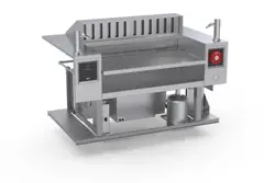
Item FC-6DV-36
(Final product may not appear as depicted.)
Table of Contents
System Overview .......................................................... 2
Fire Suppression System Installation ...................... 3
FlexVent Unit Operation ............................................. 4
Fire Suppression System Operation ........................ 8
After Fire Suppression System Discharge .............. 9
Troubleshooting ............................................................ 10
Service and Repair ....................................................... 10
Warranty Statement for The Vollrath Co. L.L.C. .... 10
WARNING
CAUTION
2
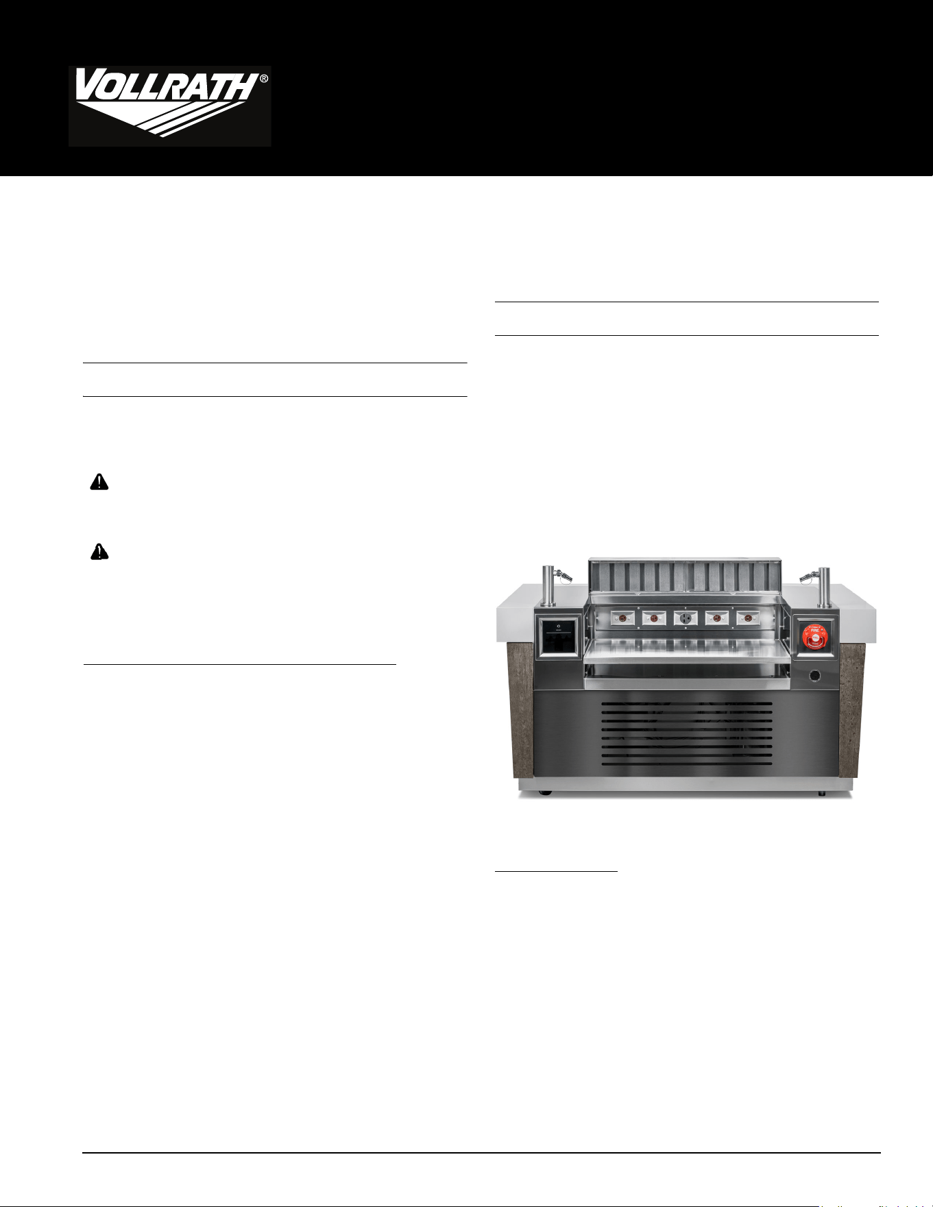
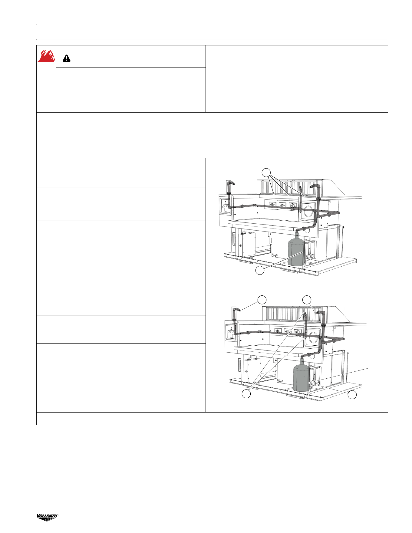
SYSTEM OVERVIEW
The FlexVent™ unit consists of three integrated systems:
• FlexVent Ventilation and Filtration System
• Fire Detection System
•ANSUL
®
R-102 Restaurant Fire Suppression System
A. Discharge Nozzles — Appliance (2)
B. Grease Filters (2)
C. Grease Tray (1)
D. Man
ual Pull Station
E. Fire Suppression System Arming View Window
F. 1.5 Gallon ANSULEX R-102 Tank, ANSULEX Fire
Suppressant*
G. Electrical Outlets*
H. Pressure Control**
I. Interlock Box**
J. Circuit Breakers and Box*
K. User Control
L. Nitrogen (N) Cartridge LT-20-R*
M. ANSUL Automan Regulated Release Assembly
N. Fan Motor
O. Vent Hood
P. Plenum Assembly
Q. Damper Assembly
R. Discharge Nozzles (Duct) (2)
S. ANSUL Detector Brackets w/ Fusible Links (3)
T. Lift and Mounting Pads
*Supplied and installed separately.
**For service technician use.
D
K
B
F
J
E
C
G
H
I
L
A
O
P
N
M
Q
R
S
T
FLEXVENT™ SLIDE-IN WITH DOWNDRAFT VENT SYSTEM AND FIRE SUPPRESSION OPERATOR’S MANUAL
FLEXVENT™ SLIDE-IN WITH DOWNDRAFT VENT SYSTEM AND FIRE SUPPRESSION OPERATOR’S MANUAL
3
FIRE SUPPRESSION SYSTEM INSTALLATION
WARNING
NOTICE: The Fire Suppression System must be charged by an
authorized ANSUL
®
representative before it will operate.
NOTICE: The installer and owner assume full responsibility for
the unit and electrical appliance set up and compliance with all
applicable codes and regulations.
Fire, Injury, Death Hazard
This unit must be installed and adjusted by a qualified
technician in accordance with all federal, state, and
local codes. Failure to install, adjust, or maintain this
unit properly can result in property damage, injury, or
death.
The following information is for use by authorized ANSUL representatives only. Refer to ANSUL documentation for the
following steps.
ANSUL representative to supply:
• Carbon Dioxide (CO
2
) or Nitrogen (N) cartridge
• ANSULEX Low pH Liquid Fire Suppressant
Fusible Links and Gas Cartridges
A ANSUL Model SL Fusible Link 165°F
B LT-20-R Cartridge (Not supplied)
1. Replace the three temporary test links with the supplied
165°F SL Fusible Links.
2. Install the Carbon Dioxide (CO
2
) or Nitrogen (N) cartridges
onto the ANSUL Automan Regulated Release Assembly.
Fire Extinguishing Tank and Nozzles
A
ANSUL R-102 1W Nozzle (Appliance)
B
ANSUL R-102 1W Nozzle (Duct)
C
ANSUL R-102 1.5 Gallon Tank
Fill the agent tank with ANSULEX low pH Liquid Fire
Suppressant.
NOTICE: Final product may not appear as depicted.
A
B
A A
B
C
4
FLEXVENT™ UNIT OPERATION
OVERVIEW
The FlexVent unit will only operate when the ANSUL
®
Fire Suppression System is charged, and the Grease Filters and Particulate
Filters are properly installed.
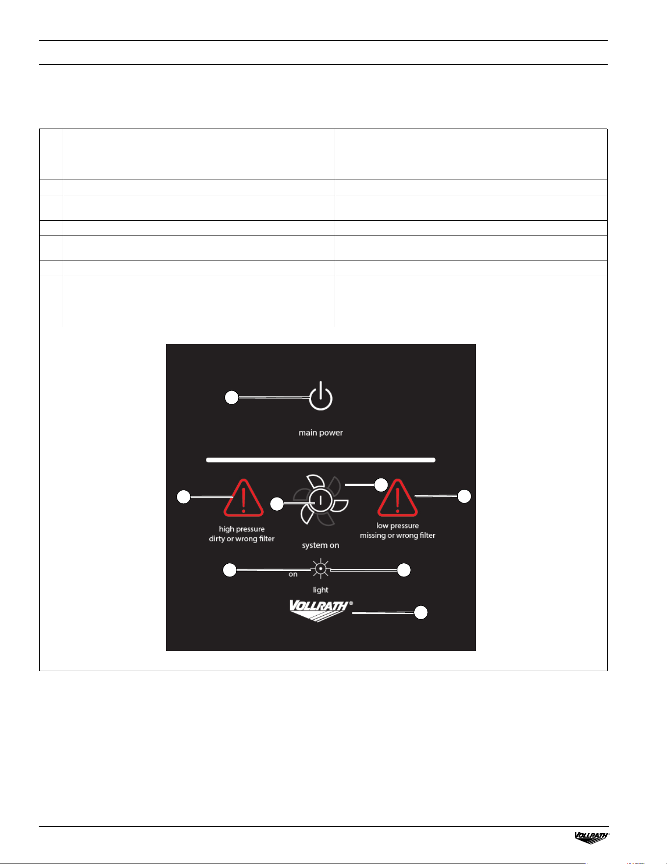
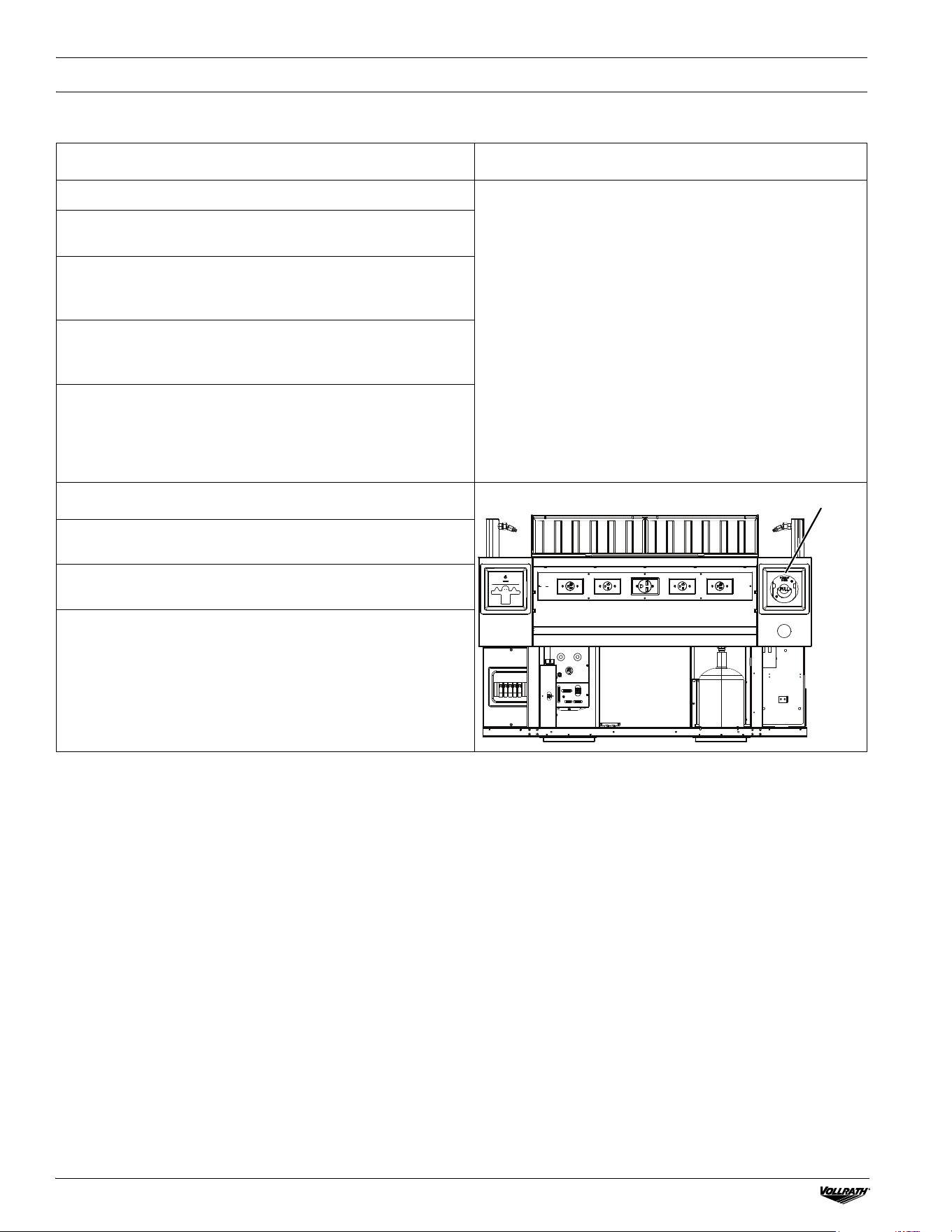
Item Description Function
A Main Power Indicator
The logo will glow when unit power is on.
NOTICE: If the Vollrath logo is not illuminated, there is
no power to the FlexVent unit.
B Main Power Switch Turns the control system on or off.
C System On/Off Switch and Indicator
Turns the vent fan and power to the electrical appliance outlets
on or off.
D System On/Off Indicator Indicates the unit is running.
E Low Pressure Indicator
Indicates a filter is missing, improperly installed, or not the
correct type.
F High Pressure Indicator Indicates the filters are dirty or are not the correct type.
GLED Light Switch
Optional, switches on the optional lighting (may not be
configured).
H LED Light Indicator
Optional, indicates when optional lighting is ON.
NOTICE: As depicted
indicates lights are on.
A
B
C
F
E
D
G H
FLEXVENT™ SLIDE-IN WITH DOWNDRAFT VENT SYSTEM AND FIRE SUPPRESSION OPERATOR’S MANUAL
FLEXVENT™ SLIDE-IN WITH DOWNDRAFT VENT SYSTEM AND FIRE SUPPRESSION OPERATOR’S MANUAL
5
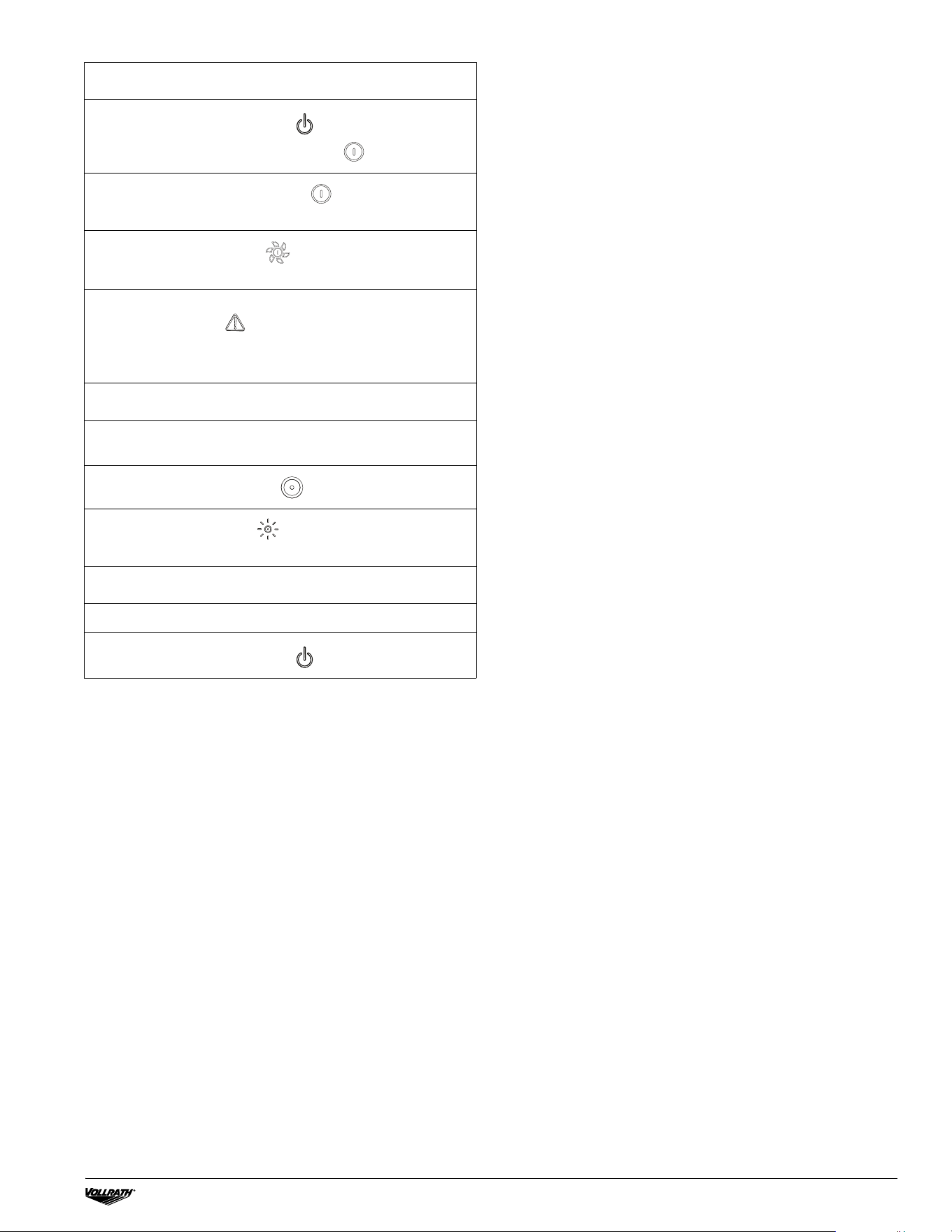
Operation
1. Touch the Main Power Switch to turn the control
system on. The System Start Indicator will illuminate.
2. Touch the System On/Off Switch to start the vent fan
motor and energize the electrical appliance outlets.
3. The System On Indicator illuminates when the fan
motor is on.
NOTICE: If the Low Pressure Indicator or High Pressure
Indicator illuminates , the system will shut down. Reset
the system by turning off the main power. Turn the power
back on once the error causing the warning has been
corrected.
Optional LED Lighting
The optional LED Light Switch will not display if this option
has not been configured.
1. Touch the LED Light Switch to turn light(s) ON or OFF.
2. The LED Light Indicator will illuminate when the LED
lights are switched ON.
Shutdown
1. Turn off the electrical cooking appliances.
2. Touch the Main Power Switch to turn the system OFF.
6
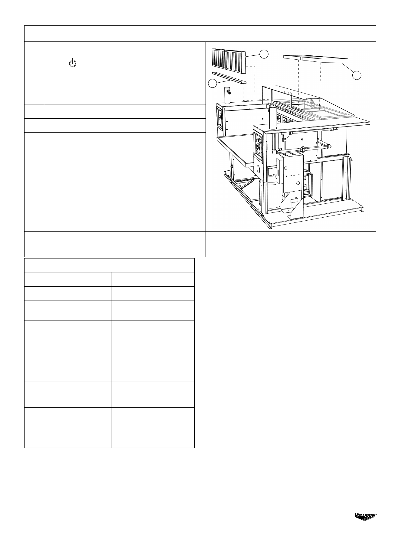
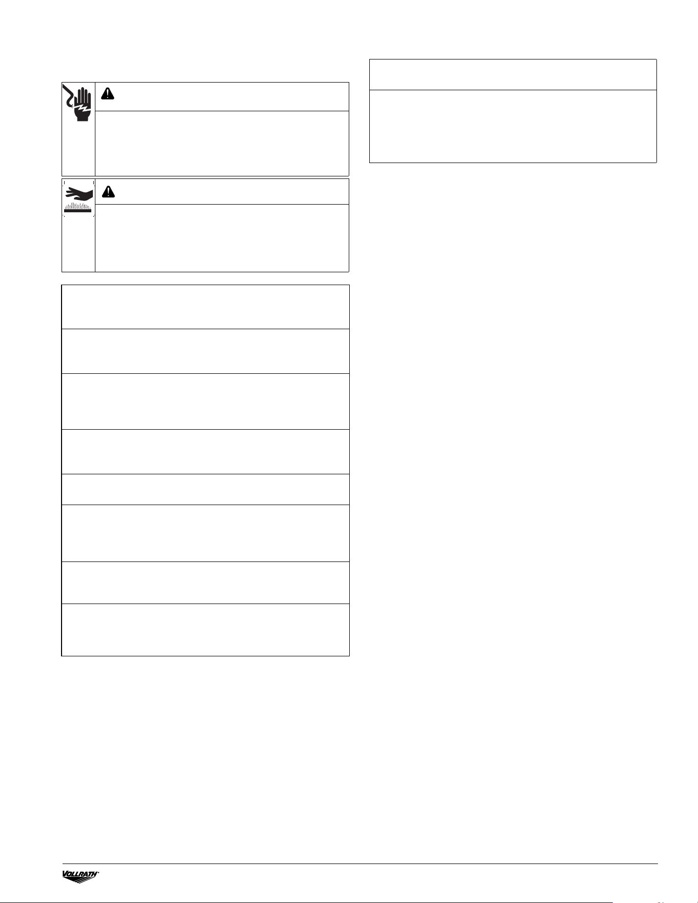
Remove Filters
1.
Turn off the electrical cooking appliances.
2.
Touch to turn the unit off.
3.
Lift the Grease Filters up, pull the bottom forward, then
down and out.
4.
Lift the Drip Tray straight up to remove it.
5.
Lift the Particulate Filters straight up to remove them.
6.
Replace filters in reverse order.
NOTICE: Ensure the Particulate Filters are properly oriented
per the label.
A. Grease Filters (2) 352035-2 B. Drip Tray 352034-2
C. Particulate Filters (2) 352010-1
A
B
C
System Cleaning and Maintenance
Procedure Inspected
System Cleaning
Monthly Interlock System
Test
Quarterly Plenum Cleaning
Fire Suppression System
Maintenance
Semi-Annual Fire
Suppression Inspection &
Maintenance
Annual Fire Suppression
System Inspection &
Maintenance
12-Year Fire Suppression
System Inspection &
Maintenance
Maintenance & Service Log
FLEXVENT™ SLIDE-IN WITH DOWNDRAFT VENT SYSTEM AND FIRE SUPPRESSION OPERATOR’S MANUAL
FLEXVENT™ SLIDE-IN WITH DOWNDRAFT VENT SYSTEM AND FIRE SUPPRESSION OPERATOR’S MANUAL
7
Cleaning
Clean your FlexVent™ Unit daily.
WARNING
Fire Hazard
Do not allow grease to accumulate on any surfaces of the
appliance, or areas in and around the cooking area.
Accumulated grease could result in a fire hazard.
WARNING
Electrical Shock Hazard
Keep water and other liquids from entering the unit. Liquid
in the unit could cause an electrical shock. Do not spray
water or cleaning products. Liquid could contact the
electrical components and cause a short circuit or an
electrical shock.
CAUTION
Burn Hazard
Do not touch hot liquid or heating surfaces while unit is
heating or operating.
Hot liquids and food can burn skin. Induction heating
surfaces heat very rapidly. Allow the heating surface to
cool before handling.
NOTICE: Do not use abrasive materials, scratching cleansers, or
scouring
pads to clean the unit. These can damage the finish.
Wipe the exterior of the unit.
Wash Grease Filters, Grease Tray and Vent Hood.
NOTICE: Failure to install the Grease Tray will allow grease
and moisture from the Grease Filters to drop into the vent,
creating both a safety hazard and a health hazard.
1. Touch to turn off the unit. Unplug electrical cooking
appliances; allow to cool.
2. Clean electrical cooking appliances per their respective
instructions.
NOTICE: Carefully remove electrical cooking appliances from
the unit if necessary to clean surround or appliances.
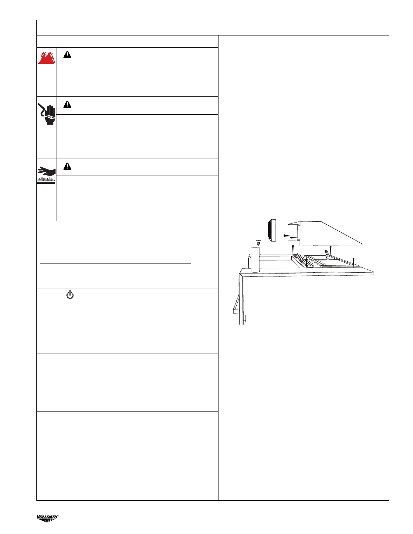
3. Lift the Vent Hood and Grease Filters to remove them.
4. Empty the Grease Tray into an approved collection receptacle.
5. Wash Grease Filters, Vent Hood, and Grease Tray with mild
detergent and warm water. Rinse and dry Grease Filters with a
clean, soft nonabrasive cloth.
NOTICE: Grease Filters can be washed and are dishwasher
safe; Particulate Filters must be replaced with new filters when
very dirty/clogged, after a fire, or approximately every six
months.
6. Use a damp cloth and mild soap to wipe exterior surfaces of
the unit, including the electrical cooking appliance space.
7. Thoroughly wipe soap away with a water-dampened cloth and
dry surfaces with clean non-abrasive cloth. Residue could
corrode the surface.
8. Install Grease Filters, Grease Tray, and Vent Hood.
NOTICE: Visually inspect the four Discharge Nozzles. Verify
the Nozzle Caps are in place. Contact your local ANSUL
®
authorized representative if the caps are missing and/or the
nozzles need to be repositioned.
NOTICE: More extensive cleaning, such as the inside of the
plenum and duct assembly, shall be conducted by an ANSUL
distributor or professional hood cleaning service upon semi-
annual inspection and fire suppression system maintenance.
8
FLEXVENT™ FIRE SUPPRESSION SYSTEM OPERATION
NOTICE: The Fire Protection System utilized with this appliance
is an ANSUL
®
R-102 RESTAURANT FIRE SUPPRESSION
SYSTEM.
Owners Role in Fire Protection Controls and Operation
• Keep all kitchen units free of grease build-up. In the unlikely event of a fire:
• The integrated ANSUL Fire Suppression System will
automatically deploy.
• Power to the electrical cooking appliances and the entire
FlexVent unit will be shut off.
• Never use or store flammable solvents or cleaners on or near
the unit.
• Keep utensils, pots, pans, or cooking materials, etc., stored in
areas that do not obstruct the Fire Suppression System
discharge.
• Never tamper with the system components (i.e., detectors,
nozzles, agent storage container(s), or the releasing
mechanism).
• DO NOT remove or reposition the nozzles. All nozzles have
been factory installed and aligned in the proper operating
position. Be sure that all nozzles have nozzle caps assembled
to them. Contact your local ANSUL authorized representative if
caps are missing and/or nozzles need to be repositioned.
Manual Activation
The ANSUL Fire Suppression System can also be manually
activated.
1. Pull the ring on the red Manual Pull Station with enough force
to activate the ANSUL Fire Suppression System.
2. When the ANSUL Fire Suppression System is manually
activated, power to the electrical cooking appliances and the
entire FlexVent Unit will shut off.
M
a
n
u
a
l
p
u
ll
s
t
a
t
io
n
FLEXVENT™ SLIDE-IN WITH DOWNDRAFT VENT SYSTEM AND FIRE SUPPRESSION OPERATOR’S MANUAL
FLEXVENT™ VERSATILE SLIDE-IN WITH DOWNDRAFT VENT SYSTEM AND FIRE SUPPRESSION OPERATOR’S MANUAL
9
AFTER FIRE SUPPRESSION SYSTEM
DISCHARGE
MAINTENANCE
WARNING
Electrical Shock Hazard
Keep water and other liquids from entering the unit.
Liquid in the unit could cause an electrical shock. Do not
spray water or cleaning products. Liquid could contact
the electrical components and cause a short circuit or an
electrical shock.
CAUTION
Burn Hazard
Make sure all surfaces to be cleaned have cooled to
room temperature. Do not use water to clean any
electrical appliances that contain hot grease or cooking
oils. Doing so may result in violent steaming and/or
spattering.
After discharge, the FlexVent™ unit will not operate until the
ANSUL
®
Fire Suppres
sion System is serviced by an
authorized ANSUL representative.
1. After discharge, clean the FlexVent unit and surrounding
area within 24 hours. Fire suppression chemicals can
cause damage to surfaces.
2. Wear rubber gloves during cleanup, as sensitive skin may
become irritated. If the ANSULEX agent or its residue
comes in contact with skin or eyes, flush thoroughly with
clean water.
3. Remove as much of the agent as possible using hot soapy
water and sponges or clean rags. Dispose of sponges or
rags in accordance with local regulations.
4. After thoroughly cleaning all affected surfaces, adequately
rinse with clean water. Dry with a soft cloth.
NOTICE: The Fire Suppression System agent is non-
toxic. However, food product and cooking grease/oil
that has come in contact with the agent will no longer
be suitable for human consumption and should be
discarded.
5. After cleanup, call your authorized ANSUL representative
to inspect, recharge, and re-commission the ANSUL Fire
Suppression System.
NOTICE: The ANSUL Fire Suppression System must be
serviced by an authorized ANSUL representative per
ANSUL documentation, and in accordance with local code
requirements and NFPA standards.
System maintenance must be performed semi-annually by an
authorized ANSUL distributor.
NOTICE: All ANSUL Fire Suppression System
maintenance must be performed by an authorized
ANSUL representative, per ANSUL documentation, and
in accordance with local code requirements and NFPA
standards. Contact your local ANSUL representative for
maintenance details.
©
2023 The Vollrath Company L.L.C. Part No. 354138
vollrathfoodservic
e.com
The Vollrath Company, L.L.C.
1236 North 18th Street
Sheboygan, WI 53081-3201 U.S.A.
Main Tel: 800.624.2051 or 920.457.4851
Main Fax: 800.752.5620 or 920.459.6573
Customer Service: 800.628.0830
Canada Customer Service: 800.695.8560
Technical Services
Induction Products: 800.825.6036 Countertop Warming
Products: 800.354.1970 All Other Products: 800.628.0832
TROUBLESHOOTING
SERVICE AND REPAIR
Serviceable parts are available on vollrathfoodservice.com.
To avoid serious injury or damage, never attempt to repair the
unit or replace a damaged power cord yourself. Do not send
units directly to The Vollrath Company LLC. Please contact
Vollrath Technical Services for instructions.
When contacting Vollrath Technical Services, please be ready
with the item number, model number (if applicable), serial
number, and proof of purchase showing the date the unit was
purchased.
WARRANTY STATEMENT FOR THE VOLLRATH CO. L.L.C.
This warranty does not apply to products purchased for
personal, family, or household use, and The Vollrath Company
LLC does not offer a written warranty to purchasers for such
uses.
The Vollrath company LLC warrants the products it
manufactures or distributes against defects in materials and
workmanship as specifically described in our full warranty
statement. Model shown comes with a Vollrath® 12-month sale
to End User OR 18-month sale to Dealer warranty against
defects in materials and workmanship. Damage from improper
use, abuse, modification, or resulting from improper packaging
during return shipment for warranty repair will not be covered
under warranty.
For complete warranty information, product registration, and
new product announcements, visit vollrathfoodservice.com.
ANSUL components are warranted by ANSUL. For details
please visit ansul.com.
ANSUL
®
is a registered trademark of Tyco Fire Protection
Products.
Problem Might be Caused By Course of Action
Unit will not operate — logo is
not illuminated.
There is no power.
• Reconnect to electrical power.
• Reset circuit breaker for unit.
• Contact Vollrath Technical Services.
The ANSUL
®
Fire Suppression
System was not properly
commissioned or needs service.
Contact an authorized ANSUL representative for repair.
Low Pressure Indicator is
illuminated and cooking unit will
not turn on.
Particulate or Grease Filters are
out of position position, missing,
or are not the correct type.
Properly install correct filters.
High Pressure Indicator is
illuminated and cooking unit will
not turn on.
Particulate or Grease Filters are
dirty or are not the correct type.
Install correct clean filters.
10/18/23