Antigravity A1 User Manual
©
2025 Antigravity All Rights Reserved
Convention
Legend
Cautions and Warnings
Tips
Glossary
Read Before Your Fist Flight
Read the following documents before the rst ight for your safety:
1. Safety Guidelines
2. Quick Start Guide
3. User Manual
It is strongly recommended to read the above-mentioned documents and watch the video tutorial before using our
product for the rst time. Follow the instructions provided in the quick start guide to prepare for your rst ight. For
more information, download and read the user manual from the ofcial website.
Video Tutorials
Scan the QR code to watch video tutorials for the safe and proper use of the product.
https://www.antigravity.tech/guide/A1
Download Antigravity App
Download the Antigravity App and follow the prompted instruction to activate your drone and other devices before rst
use. Scan the QR code above to download the Antigravity App.
Note that the ight altitude of the drone is restricted to 30 m (98.4 th) and a range of 50 m (164 ft), if the
drone has not been linked to the Antigravity App upon the rst use.
Disclaimers
This document is subject to change without prior notice as products and rmware are updated. The gures referenced
in the manual are for illustrative purposes only and may not reect the actual product. Users should refer to the
physical product.

Antigravity A1 User Manual
©
2025 Antigravity All Rights Reserved
Product Prole
����������������������������������������������������������������������������������������������������������������
1
Introduction
�������������������������������������������������������������������������������������������������������������������
1
Features
�������������������������������������������������������������������������������������������������������������������������
1
Product Overview
�����������������������������������������������������������������������������������������������������������
2
A1 Drone
������������������������������������������������������������������������������������������������������������������������
2
Front View
���������������������������������������������������������������������������������������������������
2
Rear View
����������������������������������������������������������������������������������������������������
2
Vision Goggles
���������������������������������������������������������������������������������������������������������������
3
Front View
��������������������������������������������������������������������������������������������������
3
Sides View
���������������������������������������������������������������������������������������������������
3
Bottom and Inside View
�����������������������������������������������������������������������������������
4
Grip Motion Controller
���������������������������������������������������������������������������������������������������
4
Preparation for First Flight
������������������������������������������������������������������������������������������
6
Setting Up A1 Drone
�������������������������������������������������������������������������������������������������������
6
Setting Up Vision Goggles
����������������������������������������������������������������������������������������������
7
Adjusting Lens
���������������������������������������������������������������������������������������������
10
Using Vision Correction Lenses
������������������������������������������������������������������������
11
Spacer Bracket
���������������������������������������������������������������������������������������������
12
Setting Up Grip Controller
��������������������������������������������������������������������������������������������
13
Activate Your Drone
������������������������������������������������������������������������������������������������������
14
Firmware Updates
��������������������������������������������������������������������������������������������������������
14
Linking Devices
�������������������������������������������������������������������������������������������������������������
15
Linking A1 Drone to Vision Goggles
�������������������������������������������������������������������
15
Linking Vision Goggles to Grip Controller
������������������������������������������������������������
15
Take o and Landing
�����������������������������������������������������������������������������������������������������
16
Pre-ight Checklist
������������������������������������������������������������������������������������������������������
16
Take O
������������������������������������������������������������������������������������������������������������������������
17
Landing
�������������������������������������������������������������������������������������������������������������������������
19
Auto Landing
�����������������������������������������������������������������������������������������������
19
Landing Protection
����������������������������������������������������������������������������������������
20
Precision Landing
�����������������������������������������������������������������������������������������
20
Manual Landing
��������������������������������������������������������������������������������������������
22
Post Flight Check List
����������������������������������������������������������������������������������������������������
23
Flight Safety and Control
��������������������������������������������������������������������������������������������
24
Flight Environments Requirements
�����������������������������������������������������������������������������
24
Flight Protection
�����������������������������������������������������������������������������������������
25
Flight Altitude and Distance Restriction
��������������������������������������������������������������
25
Flight Safety Best Practice
��������������������������������������������������������������������������������������������
26
RTH and Obstacle Avoidance Safety Notice
�����������������������������������������������������������������
27
Return to Home (RTH)
�����������������������������������������������������������������������������������
27
Obstacle Avoidance Safety Notice
���������������������������������������������������������������������
28
How to Control Your Drone
�����������������������������������������������������������������������������������������
28
Basic Operations
����������������������������������������������������������������������������������������������������������
28
Horizontal Flight
�������������������������������������������������������������������������������������������
29
Adjusting Heading of the Drone
������������������������������������������������������������������������
29
Climbing and Diving
��������������������������������������������������������������������������������������
30
Taking Off and Landing
��������������������������������������������������������������������������������
31
Contents

Antigravity A1 User Manual
©
2025 Antigravity All Rights Reserved
Stopping the Motors Mid-air
����������������������������������������������������������������������������
31
Controlling in Free Motion Mode
������������������������������������������������������������������������
32
Controlling in FPV Mode
���������������������������������������������������������������������������������
33
Switching Between Control Mode
����������������������������������������������������������������������
34
A1 Drone
���������������������������������������������������������������������������������������������������������������������������
35
Flight Mode
�������������������������������������������������������������������������������������������������������������������
35
Controlling Mode
����������������������������������������������������������������������������������������������������������
36
FreeMotion Mode
�����������������������������������������������������������������������������������������
36
Flight Indicators
������������������������������������������������������������������������������������������������������������
36
Before Taking Off
�����������������������������������������������������������������������������������������
37
After Take-off
�����������������������������������������������������������������������������������������������
38
Return to Home (RTH)
��������������������������������������������������������������������������������������������������
38
Introduction to RTH
���������������������������������������������������������������������������������������
38
Home Point
������������������������������������������������������������������������������������������������
38
Updating Home Point
�������������������������������������������������������������������������������������
39
RTH Process Breakdown
���������������������������������������������������������������������������������
40
RTH Flight Maneuver Strategies
�����������������������������������������������������������������������
43
RTH Risk Notice
�������������������������������������������������������������������������������������������
43
Obstacle Avoidance and Landing
����������������������������������������������������������������������������������
43
Obstacle Avoidance Overview
���������������������������������������������������������������������������
43
Obstacle Avoidance
���������������������������������������������������������������������������������������
44
Enabling Obstacle Avoidance
���������������������������������������������������������������������������
45
Obstacle Avoidance Action
������������������������������������������������������������������������������
45
Propeller Guards
�����������������������������������������������������������������������������������������������������������
45
Installing the Propeller Guards
�������������������������������������������������������������������������
45
Propellers
���������������������������������������������������������������������������������������������������������������������
47
How to Replace Propellers
�������������������������������������������������������������������������������
47
Flight Battery
����������������������������������������������������������������������������������������������������������������
48
Safety Notice for Flight Battery
�������������������������������������������������������������������������
48
Activation of the Flight Battery
��������������������������������������������������������������������������
49
Using the Flight Battery
����������������������������������������������������������������������������������
49
Charging the Flight Battery
������������������������������������������������������������������������������
51
Battery Level Indicator
�����������������������������������������������������������������������������������
51
Battery Charging Hub
���������������������������������������������������������������������������������������������������
52
Battery Charging Hub Overview
������������������������������������������������������������������������
52
Regular Charging
������������������������������������������������������������������������������������������
53
Smart Power Pooling
�������������������������������������������������������������������������������������
54
Power Bank
�������������������������������������������������������������������������������������������������
55
Battery Charging Troubleshooting
���������������������������������������������������������������������
56
Transferring Footages
��������������������������������������������������������������������������������������������������
57
Quick Reader
���������������������������������������������������������������������������������������������
57
Quick Transfer from Antigravity App
�������������������������������������������������������������������
58
Vision and Infrared Sensing System
����������������������������������������������������������������������������
58
Features
�����������������������������������������������������������������������������������������������������
58
Vision and Infrared System Safety Notices
�����������������������������������������������������������
58
Vision Position Detection Range
�����������������������������������������������������������������������
59
Flight Recorder
�������������������������������������������������������������������������������������������������������������
59
Vision Goggles
�����������������������������������������������������������������������������������������������������������������
59
Vision Goggles Overview
����������������������������������������������������������������������������������������������
60
Home Button
�����������������������������������������������������������������������������������������������
60
Volume Buttons
��������������������������������������������������������������������������������������������
60
MicroSD Card Slot
�����������������������������������������������������������������������������������������
60
Power Port
�������������������������������������������������������������������������������������������������
60

Antigravity A1 User Manual
©
2025 Antigravity All Rights Reserved
Virtual Beam
�����������������������������������������������������������������������������������������������������������������
62
Basic Operations
�����������������������������������������������������������������������������������������
62
Re-center the Menu
���������������������������������������������������������������������������������������
63
Vision Goggles Menus
���������������������������������������������������������������������������������������������������
64
Flight Menu
������������������������������������������������������������������������������������������������
64
Vision Goggle Menu
���������������������������������������������������������������������������������������
66
Quick Menu
�������������������������������������������������������������������������������������������������������������������
68
Outer Display
���������������������������������������������������������������������������������������������������������������
69
Outer Display Overview
����������������������������������������������������������������������������������
69
Video Playback
�������������������������������������������������������������������������������������������������������������
70
Exporting the Footages from Vision Goggles
���������������������������������������������������������������
70
Storage
�����������������������������������������������������������������������������������������������������
70
Exporting Footages from Vision Goggles
������������������������������������������������������������
70
Exporting Footages from SD Card
����������������������������������������������������������������������
70
Video See-Through
�������������������������������������������������������������������������������������������������������
71
Vision Goggles Safety Notices
��������������������������������������������������������������������������������������
71
Grip Motion Controller
�������������������������������������������������������������������������������������������������
72
Power Button and Battery Level Indicator
�������������������������������������������������������������������
72
Powering On/Off the Grip Motion Controller
���������������������������������������������������������
72
Charging the Grip Motion Controller
�������������������������������������������������������������������
72
Battery Level Indicators
���������������������������������������������������������������������������������
72
Grip Motion Controller Buttons
������������������������������������������������������������������������������������
73
Grip Motion Controller Signal
��������������������������������������������������������������������������������������
76
Alert Sounds
�����������������������������������������������������������������������������������������������������������������
76
Low Battery Alert
������������������������������������������������������������������������������������������
76
RTH Alert
�������������������������������������������������������������������������������������������������
76
Antigravity App
���������������������������������������������������������������������������������������������������������������
76
Intelligent Flight
������������������������������������������������������������������������������������������������������������
77
Deep Track
��������������������������������������������������������������������������������������������������������������������
77
Deep Track
��������������������������������������������������������������������������������������������������
77
Using Deep Track
������������������������������������������������������������������������������������������
78
General Safety Notices for Deep Track
����������������������������������������������������������������
81
Sky Genie
����������������������������������������������������������������������������������������������������������������������
82
Introduction to Sky Genie
��������������������������������������������������������������������������������
82
Using Sky Genie
�����������������������������������������������������������������������������������������
83
Sky Path
������������������������������������������������������������������������������������������������������������������������
85
Introduction to Sky Path
���������������������������������������������������������������������������������
85
Using Sky Path
���������������������������������������������������������������������������������������������
86
Product Specication
���������������������������������������������������������������������������������������������������
89
A1 Drone
�����������������������������������������������������������������������������������������������������������������������
89
Vision Goggles
���������������������������������������������������������������������������������������������������������������
94
Grip Motion Controller
��������������������������������������������������������������������������������������������������
97
Frequently Asked Questions (
FAQ
)
���������������������������������������������������������������������������
97
Appendix
��������������������������������������������������������������������������������������������������������������������������
99
Compliance Information
�����������������������������������������������������������������������������������������������
99

1
Antigravity A1 User Manual
©
2026 Antigravity All Rights Reserved
Product Profile
Introduction
The Antigravity A1 is an drone that dees limits, that combines advanced hand-eye coordination technology with an
immersive ying experience. By using the Antigravity Vision goggles and the Antigravity A1Grip Motion controller, users
can experience free-ight motion control, real-time perception of ight attitude, precise control, and panoramic view
shooting.
Features
� 8K 360 Video: Our 8K 360° camera captures all angles during the ight.
� Free Motion Mode: Unlock the head movement against the ight direction, enables intuitive y experience.
� Flight Safety: Auto landing gear retraction ensures worry-free ight. Obstacle avoidance system detects obstacles
on the ight path.
� Payload Detection:
Drone lands when detecting excessive payload. Ensure the drone is compliant with recreational use.
� The maximum flight speed of the drone is obtained at sea level in windless conditions. The maximum
flight time is defined as the drone is flying at a cruise speed in windless conditions.
� The usage of the 5.8 GHz frequency band is subject the availability of countries or regions. In such cases,
the drone will automatically disable this frequency band. Please ensure compliance with local laws and
regulations. The 5.1 GHz frequency band is only available in countries and regions where it is permitted
by law.
� The availability of the High-Capacity Flight Battery is restricted to certain countries and regions. Contact
the local reseller or visit the official store for more information.
� The MTOM (Maximum Take-off Mass) of the drone will exceed 249 grams, when the using the High-
Capacity Flight Battery. Please ensure compliance with local laws and regulations regarding takeoff
weight with using the High-Capacity Flight Battery.
2
Antigravity A1 User Manual
©
2026 Antigravity All Rights Reserved
Product Overview
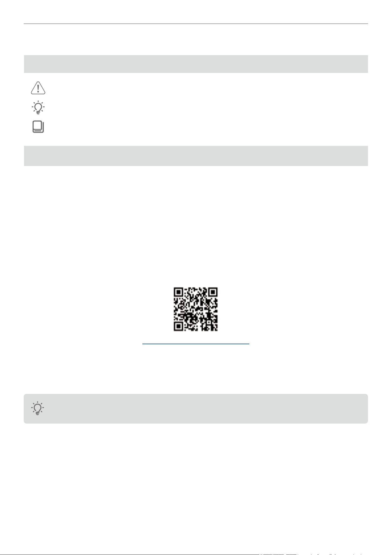
A1 Drone
Front View
Item Description Item Description
1 360° Camera 6 Motor
2 Forward Vision Sensor 7 Landing Gear
3 Front Indicator 8 Downwards Infrared Sensor
4 Forward Vision Sensor 9 Landing Light
5 Downward Vision Sensor
Rear View
Item Description Item Description
1 Power Button 4 Micro-SD Card Slot
3
Antigravity A1 User Manual
©
2026 Antigravity All Rights Reserved
2 Flight Battery Latch 5 Type-C Port
3 Flight Battery Level Indicator 6 Flight Status Indicator
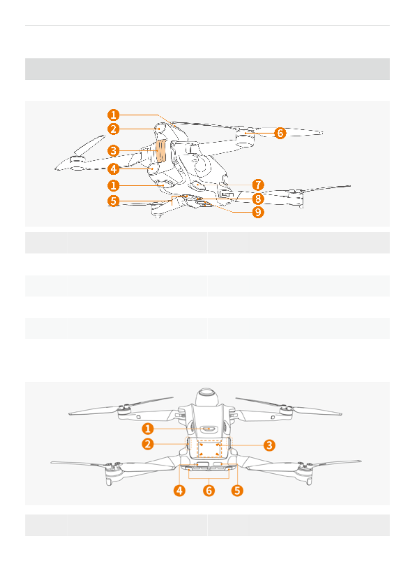
Vision Goggles
Front View
Item Description Item Description
1 Antennas 4 Video See-Through Camera
2 Venting Port 5 Diopter Adjustment Knobs
3 Outer Display 6 Touchpad
Sides View
Item Description Item Description
1 Home / Linking Button 3 Volume Button
2 Foam Padding 4 Speaker
4
Antigravity A1 User Manual
©
2026 Antigravity All Rights Reserved
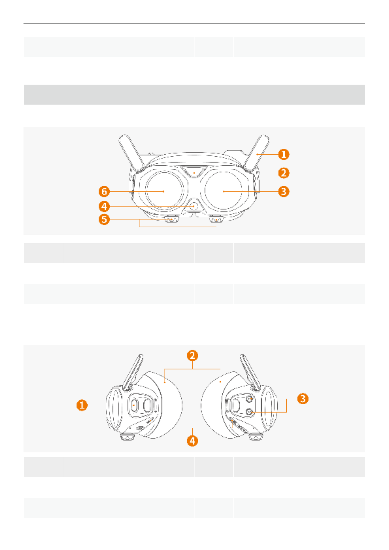
Bottom and Inside View
Item Description Item Description
1 Data Port (Unavailable for charging) 4 Memory Card Slot
2 Diopter Adjustment Knobs 5 De-fog Inlet
3 USB-C to DC Power Cable Port 6 Diopter Lens
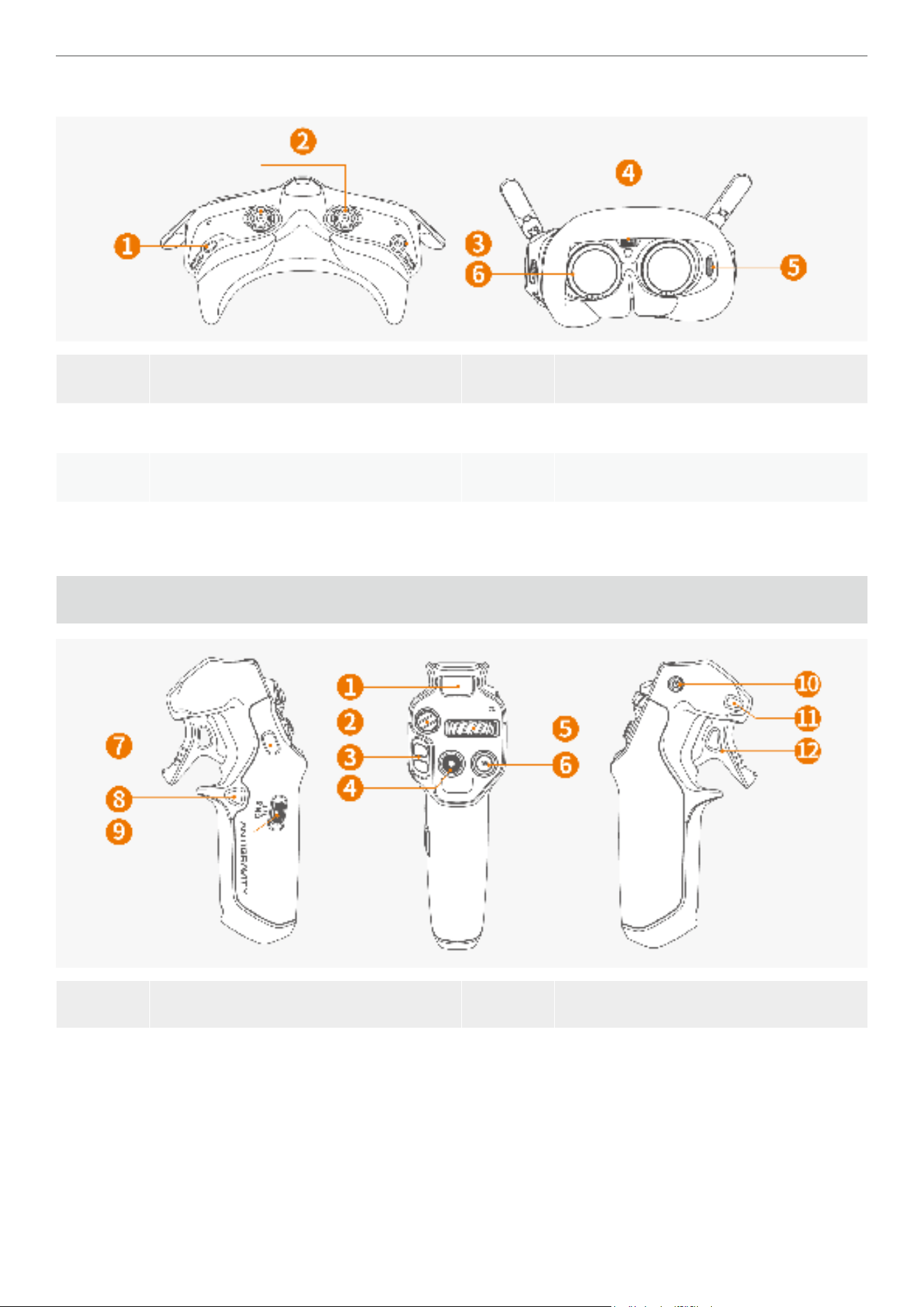
Grip Motion Controller
Item Description Item Description
1
Battery Level Indicator:
Display the current battery level.
7
Customized C2 Button:
Double press to extend or retract the
landing gear.

5
Antigravity A1 User Manual
©
2026 Antigravity All Rights Reserved
2
Emergency Brake / RTH Button:
Press once to brake and hovers the
drone.
Press and hold to activate RTH (Return To
Home).
8
Customized C1 Button:
While the drone is in midair, double press
to turn on or off the landing lights.
3
Flight Slider:
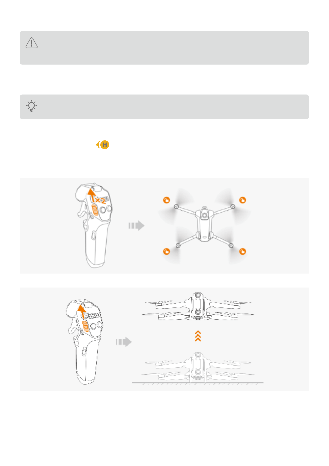
� Pre-ight: Push upward twice in short
burst to start the motors (idle mode).
Push downward twice to cancel.
� When motor starts: Push the slider
upward and hold for over 2 seconds to
ascent.
� Mid-ight: Push upward to ascend the
drone and downward to descend the
drone.
9
Flight Mode Toggle:
Toggle to switch between these modes
� N (Normal) mode
� S (Sport) mode
� C (Cine) mode
4
Record Button:
� In default mode: Press and hold to switch
to video mode.
� In video mode: Press once to start
recording video.
10
Power Button:
Press once then press and hold to switch
on the Grip Controller.
� When powered on, press and hold for 10
seconds to enforce shutdown.
� Press and hold for 4 seconds to enter
pairing mode.
5
360 Dial Button:
Slide left or right to adjust the live-view
and the heading of the drone.
Press inward to recenter the perspective
of the heading of the drone.
11
Menu Button:
� Press once to enter or exit the general
menu of the Vision Goggles; press and
hold to activate the shortcut menu.
6
Shutter Button:
� In default mode: Press and hold to switch
from video mode to photo mode.
� In photo mode: Short press to capture an
image.
12
Throttle Trigger:
� When controlling the drone: pull to
accelerate, release to decelerate.
� When interacting Vision Goggles: pull
to conrm selections; press and hold to
scroll menus.
6
Antigravity A1 User Manual
©
2026 Antigravity All Rights Reserved
Preparation for First Flight
Setting Up A1 Drone
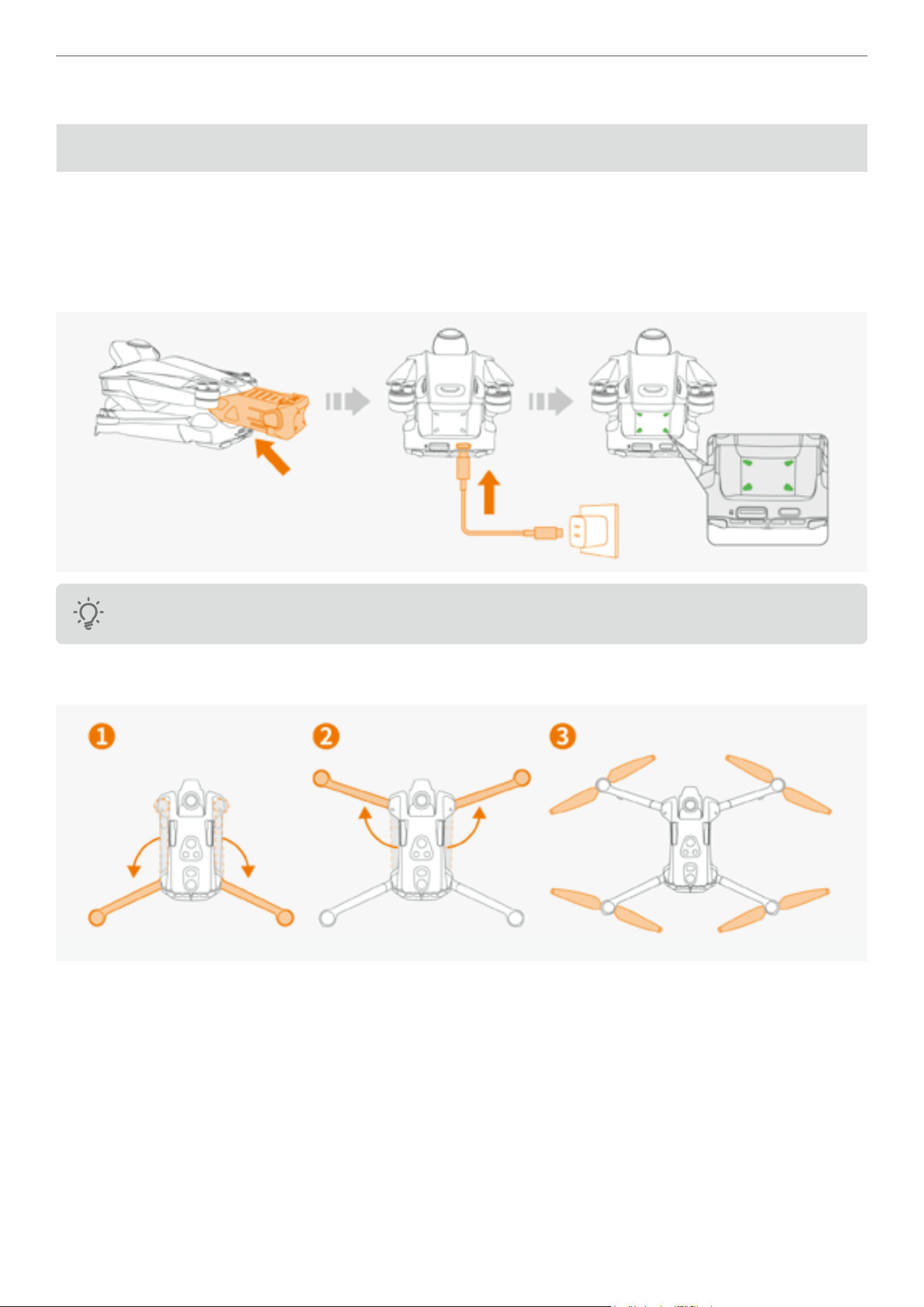
Upon delivery, the drone is in a hibernating state to maintain the battery level. Follow the steps below to prepare for
your rst ight.
1. The ight battery in the drone is in a dormant state upon delivery. You must activate the battery before using it
for the rst time. Insert the ight battery into the battery compartment, and then connect it to the drone's USB-C
charging port using a charging cable. The battery indicator light will blink green when the battery is activated.
Ensure that at least three or more battery indicator LEDs are lit before the rst use.
2. Unfold the rear arms of the drone, then unfold the front of the drone. Ensure that the all propellers are fully
deployed.
7
Antigravity A1 User Manual
©
2026 Antigravity All Rights Reserved
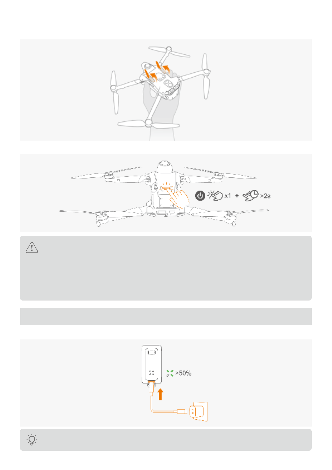
3. Flip over the drone body and manually extend the landing gear located at the bottom of the drone.
drone.
4. Press once and then press and hold the power button for more than two seconds to power on the drone.
� It is recommend to purchase the Antigravity GaN Fast Charger or other chargers that support the USB PD
protocol for optimal charging performance.
� Charge the A1 drone with the charger at a high power rate (65W or above) for optimal performance.
� The maximum charging limit voltage on the drone's charging port is 12 V.
� Peel off all stickers on the body of the drone. Make sure both the front and rear arms are unfolded and the
landing gears are deployed.
Setting Up Vision Goggles
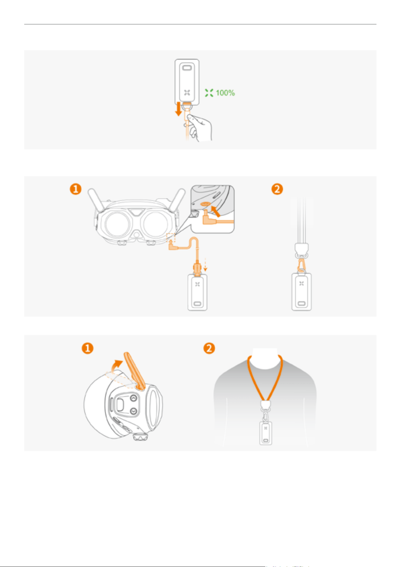
1. Prior to the rst use, charge the battery of the Vision Goggles to activate the battery.
Ensure that at least three or more battery indicator LEDs are lit before the rst use.
8
Antigravity A1 User Manual
©
2026 Antigravity All Rights Reserved
2. Unplug the power cable after the charging is complete.
3. Connect the Vision Goggles to the external Vision Goggles battery via the included USB-C to DC charging cable.
Attach the Vision Goggles battery lanyard on the buckle.
4. Unfold the antennas of the Vision Goggles and hang the Vision Goggles battery on the chest.
9
Antigravity A1 User Manual
©
2026 Antigravity All Rights Reserved
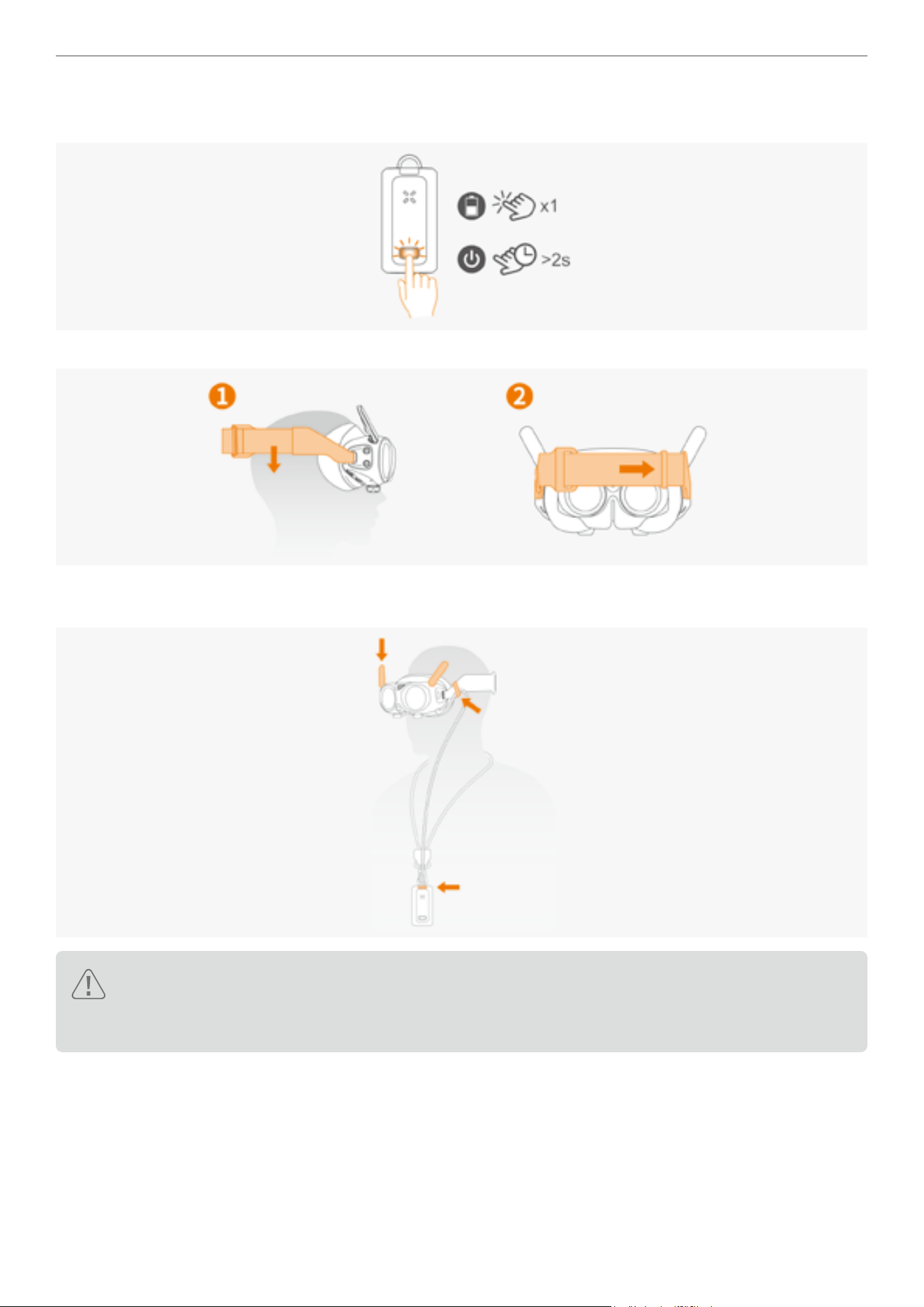
5. After charging is completed, short press the power button to display the battery level. Press and hold the power
button for more than 2 seconds to turn the power on or off.
6. Adjust the tightness of the t via the Velcro on the headband of the Vision Goggles.
7. After putting on the Vision Goggles, adjust the length of the power supply cable using the caliper on the side of the
headband if needed.
� Remove obstacles or debris around your feet before putting on the Vision Goggles to ensure safe usage.
� Before each use, ensure the connection power supply cable of the Vision Goggles is secured. Failure to
do so might cause the danger during the ight.
10
Antigravity A1 User Manual
©
2026 Antigravity All Rights Reserved
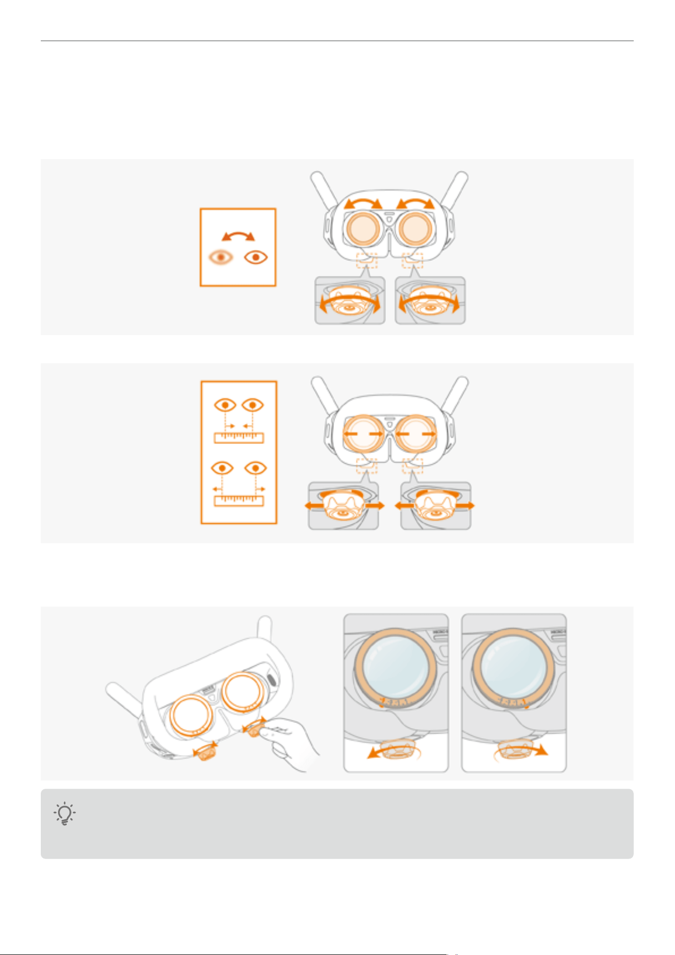
Adjusting Lens
If you require vision correction with the prescription ranging from +200° (hyperopia) to -500° (myopia), you need to
adjust the position of the lenses in the Vision Goggles to achieve the best using experience.
1. First, rotate the knobs to adjust the diopter. The diopter adjustment range is from +200° (hyperopia) to
-500°(myopia).
2
.
Slide the knobs left or right to adjust the interpupillary distance.
� Before putting on the Vision Goggles, rotate the knobs to move the markers of lens to the approximate range of
your vision correct range. Then, put on the Vision Goggles to ne-tune the diopter to achieve the optimal visual
experience. Rotate leftwards for short-sighted users and rightwards for far-sighted users.
� Diopter lenses need to be purchased separately if your vision correction range exceeds +200° to -500°.
� The diopter adjustment has a limited travel range. Adjust it with gentle range and do not exceed the
travel range, otherwise it may cause damage.
11
Antigravity A1 User Manual
©
2026 Antigravity All Rights Reserved
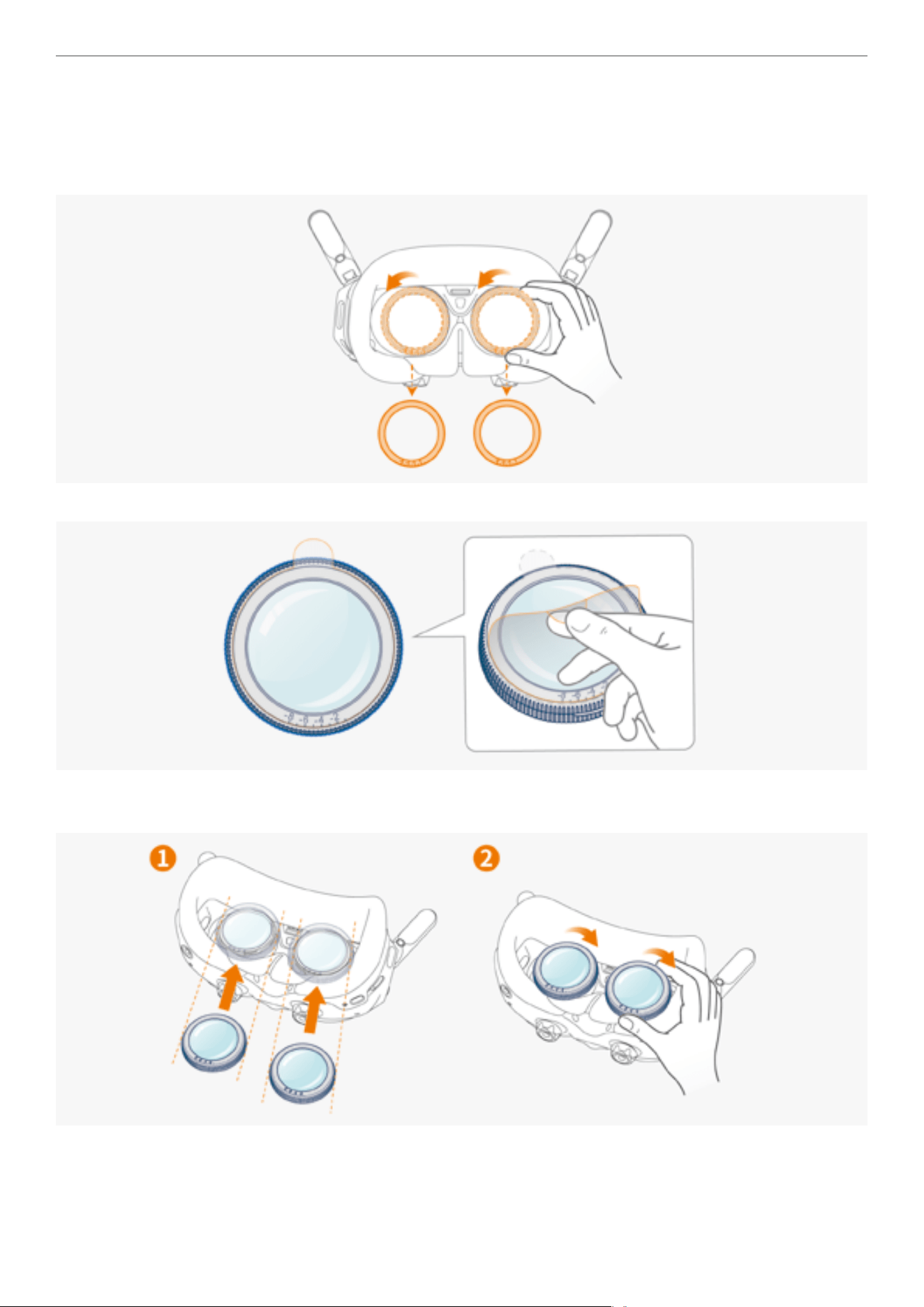
Using Vision Correction Lenses
If your myopia correction range is between -500° and -800°, you can attach a 300-degree myopia correction lens for
the optimal using experience.
1. Rotate the lens frames counterclockwise to detach them from the Vision Goggles.
2. Peel off the protective lms from the new myopia lens.
3. Mount the lenses to the lens barrels in the direction depicted in the gure below. Press it into place and rotate
clockwise to secure its place.
4. Before putting on the Vision Goggles, rotate the knobs to move the markers of lens to the approximate range of
your vision correct range. Then, put on the Vision Goggles to ne-tune the diopter to achieve the optimal visual
experience.
12
Antigravity A1 User Manual
©
2026 Antigravity All Rights Reserved
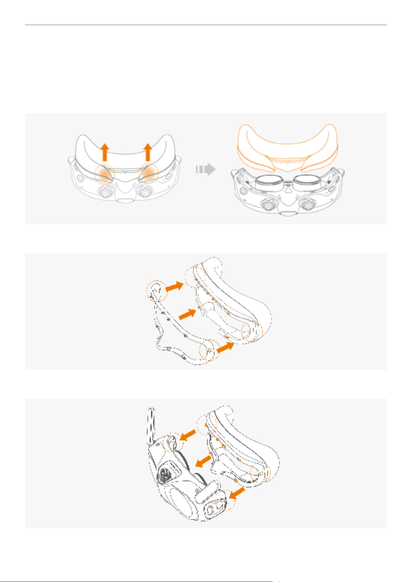
Spacer Bracket
The spacer bracket and foam padding on your Vision Goggles are pre-installed. You can choose to keep or remove
them depending on your face shape and comfort.
Install
1. To remove the foam padding, pinch and Grip both sides of the foam padding near the nose bridge. Gently pull
upward to detach the padding from the Vision Goggles.
2. Position the bracket so that its clips align with the slots on the foam padding. Press down on both sides near the
ears until the padding clicks into place.
3. Position the foam padding (with the bracket attached) so that its clips align with the slots on the Vision Goggles.
Press down on the nose bridge and both sides near the ears until the padding clicks into place.
13
Antigravity A1 User Manual
©
2026 Antigravity All Rights Reserved
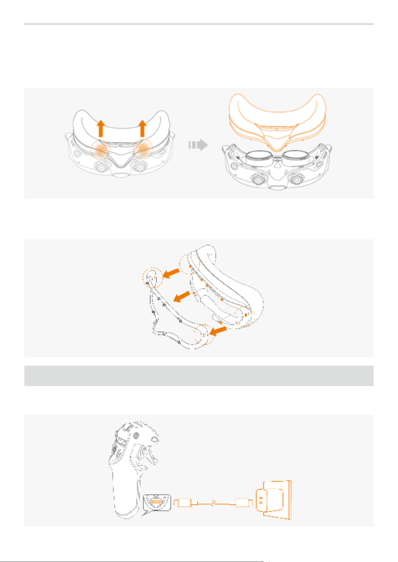
Remove
1. Removing the Foam Padding From the Vision Goggles.
a. Grip both sides of the foam padding near the nose bridge.
b. Gently pull upward to detach the padding from the goggles.
2. Removing Spacer Bracket.
a. Simultaneously push inward on both sides of the bracket.
b. Continue pushing until the bracket disengages from the Vision goggles.
Setting Up Grip Controller
1. Charge the Grip Controller to activate it when using it for the rst time. Connect the USB port to a power source to
charge your Grip Controller.
14
Antigravity A1 User Manual
©
2026 Antigravity All Rights Reserved
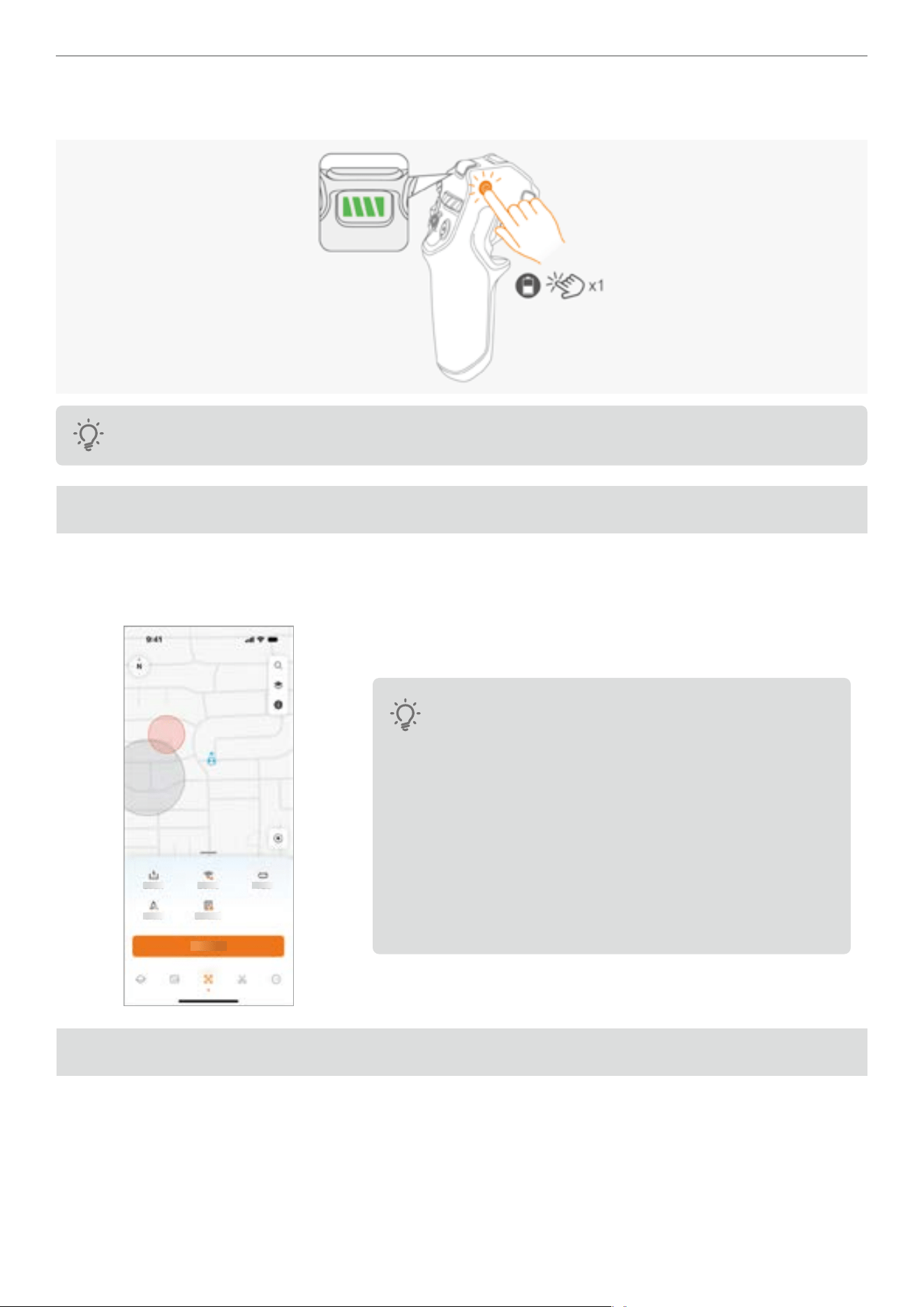
2. Press once on the power button to check the battery level. Connect the USB-C port to the power source to charge
the Grip Controller.
Ensure that at least three or more battery indicator LEDs are lit before the rst use.
Activate Your Drone
Before using the A1 drone for the rst time, you will need to activate it through the Antigravity App to comply with
regulations. Power on the A1 drone, Vision Goggles, and Grip Controller. Download the Antigravity app and ensure
Wi-Fi and Bluetooth are enabled on your mobile device. Follow the on-screen instructions to activate your drone.
� It is strongly recommended to activate your drone in a
stable Wi-Fi connected network environment. Otherwise,
it may cause activation failure.
� Ensure you have easy access to personal information
(e.g., ID card, passport) before carrying out the
activation.
� Upon successful activation, you can proceed to product
insurance service within 48 hours.
� The functionality of the drone is limited if you do not
activate your drone.
Firmware Updates
It is important to keep your rmware up to date to ensure optimal performance and compatibility with any new features
or improvements.
Make sure to regularly check for any rmware update by launching the Antigravity App, check the notications and
follow the on-screen instructions from the Antigravity app or the menu of the Vision Goggles to perform the rmware
update. For more information about how to update the rmware, refer to the corresponding section in the Appendix.
15
Antigravity A1 User Manual
©
2026 Antigravity All Rights Reserved
Linking Devices
All three devices are paired upon delivery. No linking is required under most circumstances. Linking is only required
after purchasing a new devices, follow the instructions below to link the devices:
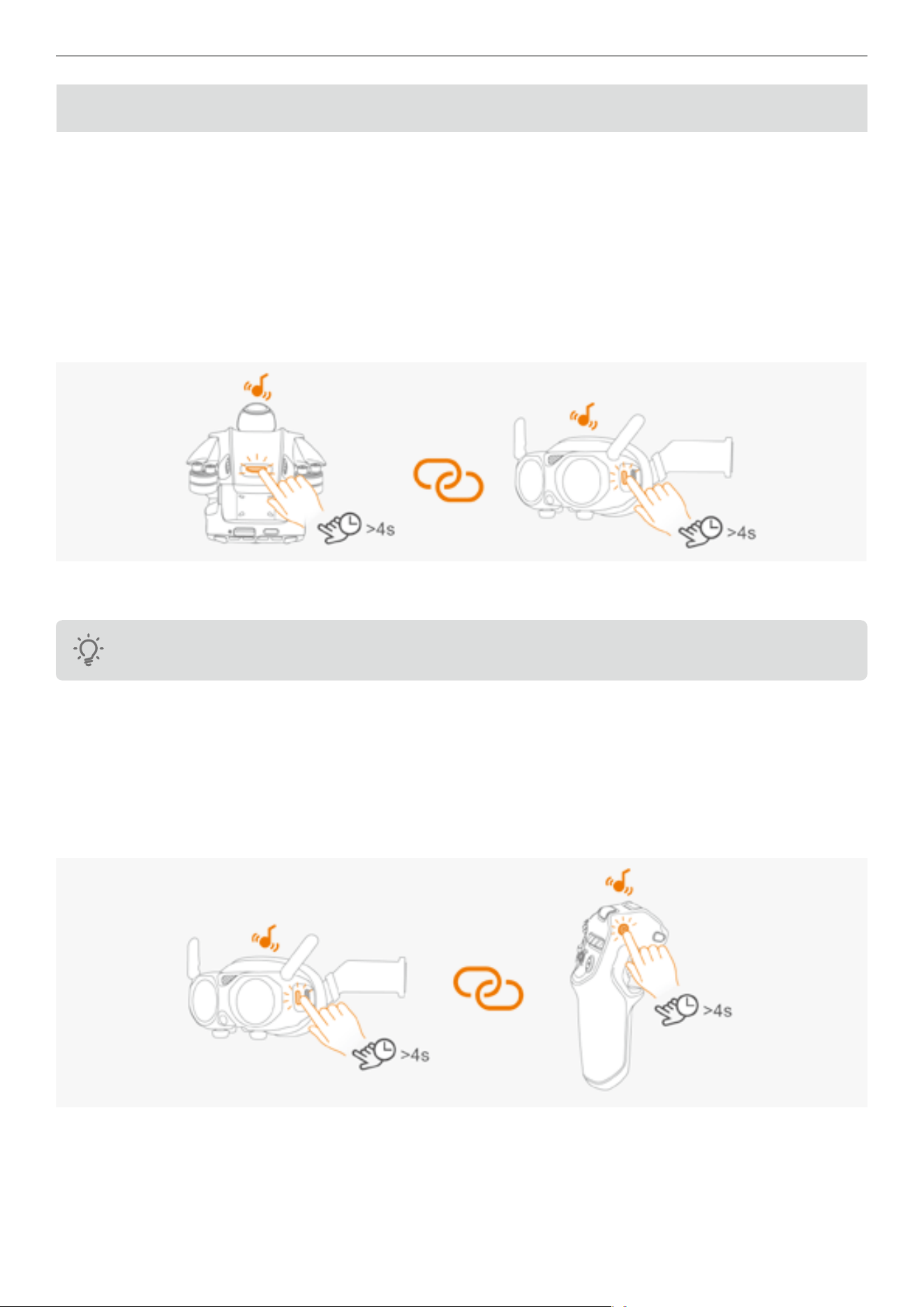
Linking A1 Drone to Vision Goggles
1. Power on both the A1 Drone and the Vision Goggles.
2. Press and hold the power button on the A1 Drone for more than 4 seconds to enter the linking state. The A1 drone
will emit a beep tone and the indicator at the front will blink green.
3. Press and hold the Home button on the Vision Goggles, and the Vision Goggles will enter the linking state and emit
a beep tone as well.
4. The user can see the live view of the drone from the Vision Goggles if the linking is successful. And the beeping
tones from both the devices will stop.
Ensure the USB port on the drone is disconnected before attempting the linking.
Linking Vision Goggles to Grip Controller
1. Power on both the Vision Goggles and Grip Controller.
2. Press and hold the Home button on the Vision Goggles, and the Vision Goggles will enter the linking state and emit
a beep tone as well.
3. Press and hold the power button on the Grip Controller, and the Grip controller will enter the linking state and emit a
beep tone. The battery level indicator will start blinking in sequence.
16
Antigravity A1 User Manual
©
2026 Antigravity All Rights Reserved
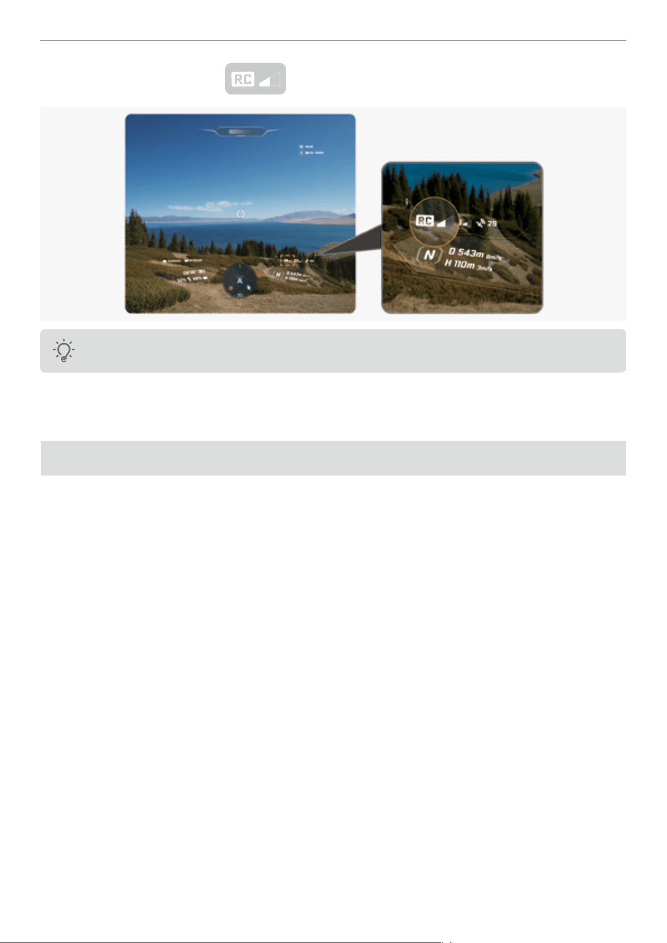
4. Check the RC signal strength icon from the live-view from the Vision Goggles. The signal icon turns
white if the linking is successful.
Ensure that the distance between devices does not exceed 0.5 meters when started linking.
Take off and Landing
This chapter provides basic instructions on how to take off and land the drone.
Pre-flight Checklist
Conducting a pre-ight inspection of your drone is an important step in safeguarding your safety and minimizing the
risk of accidents. Before each takeoff, be sure to follow the steps in the listed below:
1. Check if the ight battery and propellers are secured in place. Ensure there is no visible damage to the major
components.
2. Check if there is any sign of damage or cracks on the body of drone, the camera lens and on the propeller.
3. Check if the battery is fully charged for the A1 drone, Vision Goggles and Grip controller.
4. Check if the MicroSD card is installed on the drone.
5. Check that the landing gear can be lowered and retracted.
6. Check that the motor is running properly after it is unarmed.
7. Update the Antigravity app if necessary.
8. Check if there is dirt or stains on each of the sensors or camera lenses.
9. Check to verify only the ofcially approved accessories are installed. Unauthorized accessories installation might
affect the safe use of the drone.
10. Check if the RTH height and action is set in the Vision Goggles menu. You must set the maximum altitude, ight
distance limits, and RTH altitude in accordance with local regulations.
17
Antigravity A1 User Manual
©
2026 Antigravity All Rights Reserved
Take Off
Go through the pre-ight checklist item by item before taking off. Ensure that each step has been performed, then
follow the instructions below to take off your drone.
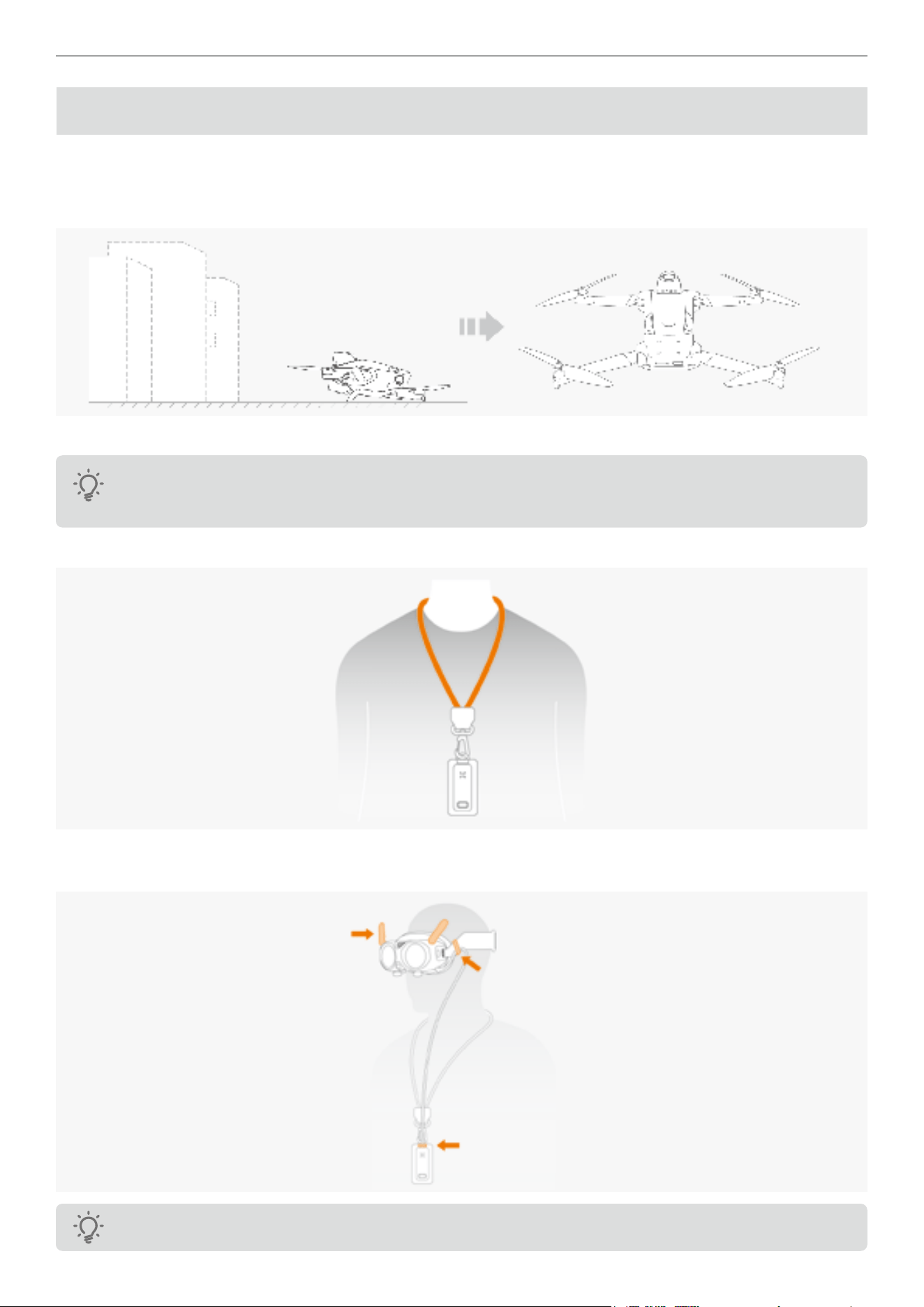
1. Place the drone in an open area with at surface and ensure the rear of the drone facing towards you.
2. Power on the devices in the sequence of A1 Drone, Vision Goggles, and lastly the Grip Motion Controller.
Press the button on the external battery to power on the Vision Goggles. For more details
,
refer to the
section “Preparation for First Flight” on page 6.
3. Place the battery lanyard around your neck as it is the recommended wearing method.
4. Extend the antenna of the Vision Goggles and ensure that the power cable of the Vision Goggles is securely
connected.
Adjust the length of the power supply cable using the caliper on the side of the headband if needed.
18
Antigravity A1 User Manual
©
2026 Antigravity All Rights Reserved
The Vision Goggles must be used with the power cord and battery provided by Antigravity. Do not attempt
to use any third party power USB C cable or batteries to power the Vision Goggles, as this may result in
serious or even irreversible damage to the Vision Goggles.
5. To ensure ight safety, you should cong the RTH and obstacle avoidance setting before each ight. Set the "Signal
Lost Behavior" to RTH and "Obstacle Avoidance Behavior" to "Brake". Ensure that the "RTH Altitude" is signicantly
higher than the tallest structure nearby.
Before putting on the Vision Goggles, we suggest familiarizing yourself with the button locations on the
Grip Controller through the ofcial documentation or video tutorials.
6. Wait for the drone's self-check to complete. If no warnings are displayed in the Vision Goggles, you can then unlock
the motors.
7. Make sure the Home point (
) is successfully recorded before attempting takeoff. Failure to do so may prevent
safe landing of your drone.
8. Unlock the motors by pushing up the ight slider in two bursts, ensuring a time interval between each burst. The
drone will now be ready to take off
.
9. Slowly push up the ight slider, the drone will take off and climb slowly to 1.2 meters (3.9 ft) and hover.
19
Antigravity A1 User Manual
©
2026 Antigravity All Rights Reserved
Landing
The drone can return and land on its recorded Home point either automatically or manually. This chapter describes the
procedure on how to land your drone safely by your Grip controller.
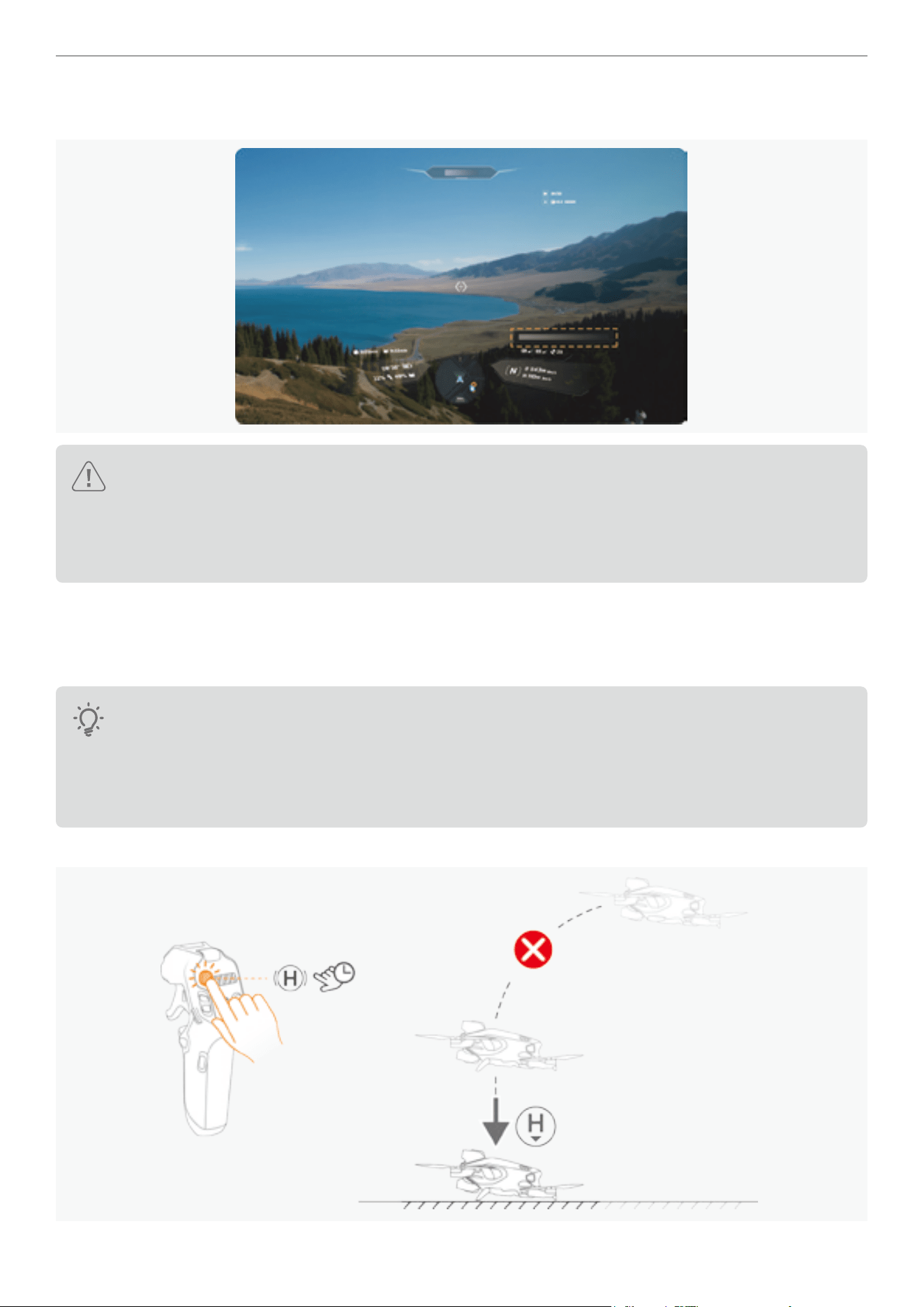
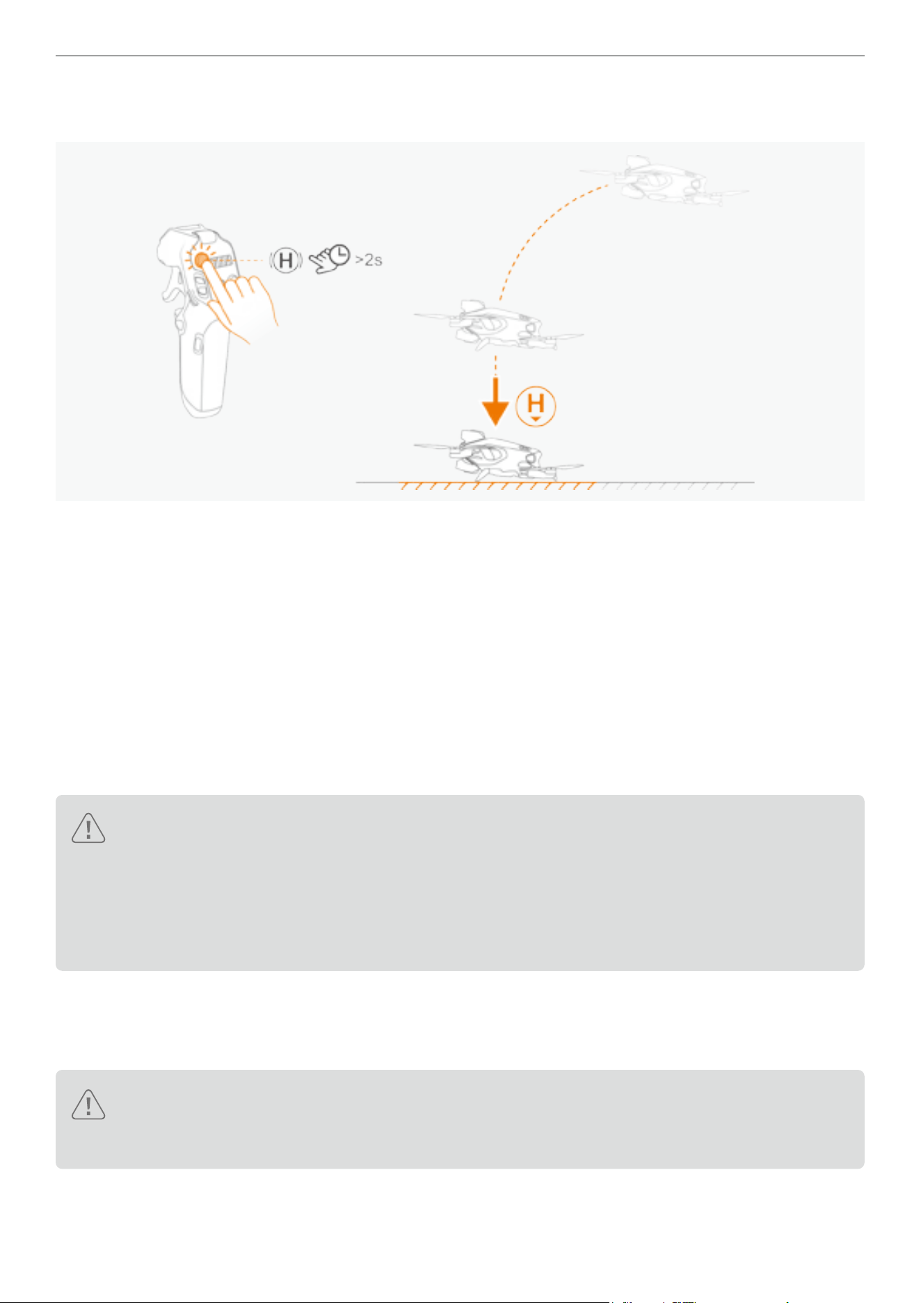
Auto Landing
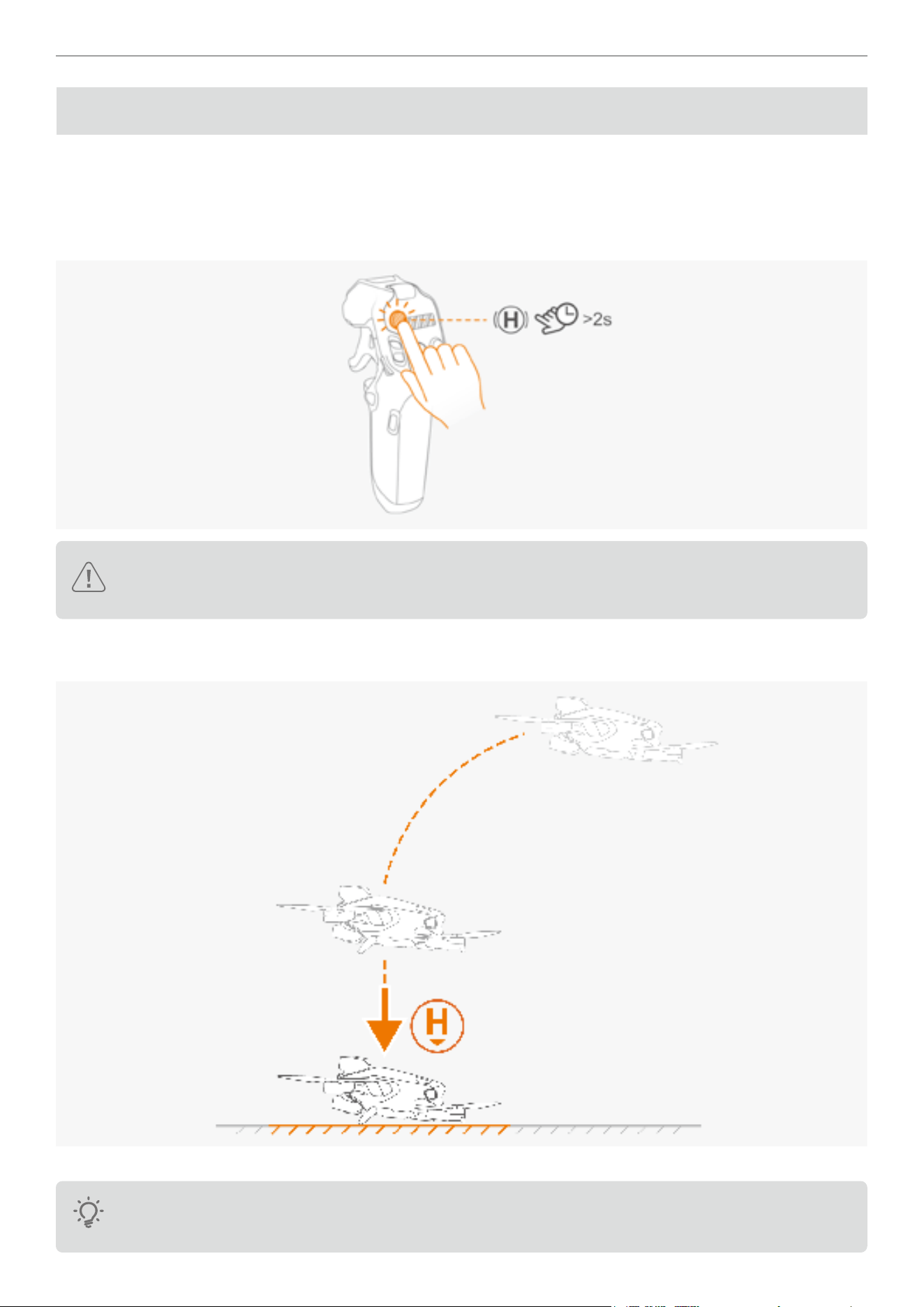
1. Press the RTH button on the Grip Controller for more than 2 seconds, the drone will proceed to RTH and land.
Make sure the Home point is recorded before activating the RTH. Do not activate the RTH if the Home
point is refreshed and recorded in an unsuitable area (e.g., near water)
2. After the Return to Home (RTH) is activated, your drone will change its heading and start to y back to its Home
point at the pre-determined RTH altitude and attempt to land itself.
3. After landing at the Home Point, the drone will stop its propellers on its own.
Upon landing is complete, it is advised to power off the A1 drone rst then the Vision Goggles and Grip
controller. Otherwise it may trigger the RTH signal lost alarms.
20
Antigravity A1 User Manual
©
2026 Antigravity All Rights Reserved
Landing Protection
When the drone is in automatic Return-to-Home (RTH) mode or in the midst of manual landing, the landing protection
automatically activates to ensure a safe landing. Follow these tips while the drone is landing:
1. If the landing area is well-lit and the conditions are detected as suitable for landing, then landing protection will
engage and run in the background to land the drone automatically.
2. When landing protection is engaged and the drone determines that the landing area is unsafe for landing (e.g.,
uneven ground or water surface), the drone will abort landing, hover, and await user input.
� Landing protection assists in judging the landing environment. However, user discretions on whether the
landing environment is suitable for lading are still required.
� If the drone experiences a system-dened emergency (such as critical low battery, battery failure, or failed
takeoff), landing protection will not take effect, and the drone will override landing protection to land itself.
� The performance of the landing protection is subject to external environments. Due to the system
limitation, the drone will keep descend and land in the below scenarios:
a. The terrain below the drone is characterized by a solid color, lack of distinct texture, dynamic texture,
reection, or dimly lit area. For instance, when the landing site is a tiled ground, dimly lit garage oor,
or swaying green eld.
b. When obstacles are present at the landing site, and the obstacle is characterized by a lack of distinct
features, reective, and monochromatic color. For instance, obstacles such as rocks or protruding tiles.
c. There are small obstacles below the drone, such as wires, small tree branches.
d. A at scene below the drone, such as trimmed bushes, at tree tops, or hemispherical shapes.
� In the following scenarios, landing protection may not be operational , and the Vision Goggles will prompt
the user that landing is aborted:
a. The terrain below the drone resembles a body of water (such as wet ground, ooded ground).
b. Textured non-at areas (slopes, steps, etc.) appear in the at area around the drone, such as a
monochromatic color car roof or small table.
Precision Landing
The drone will scan and attempt to match the terrain during the RTH process. When the drone determines that the
current terrain matches the recorded Home point, it will land with precision. It is recommended to follow the steps
below for optimal performance of precision landing.
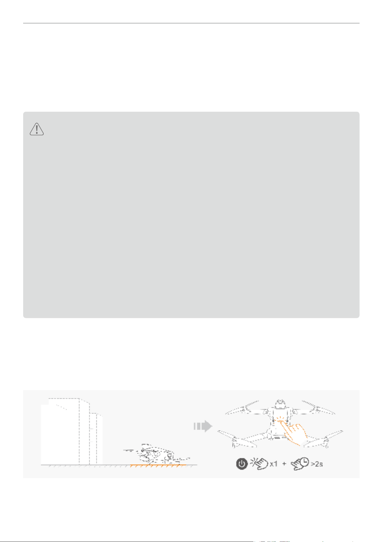
1. First, ind a spot that you think is suitable for takeoff. Place your drone on the ground rst. Then power on the drone
and allow it to search for GNSS signals.
21
Antigravity A1 User Manual
©
2026 Antigravity All Rights Reserved
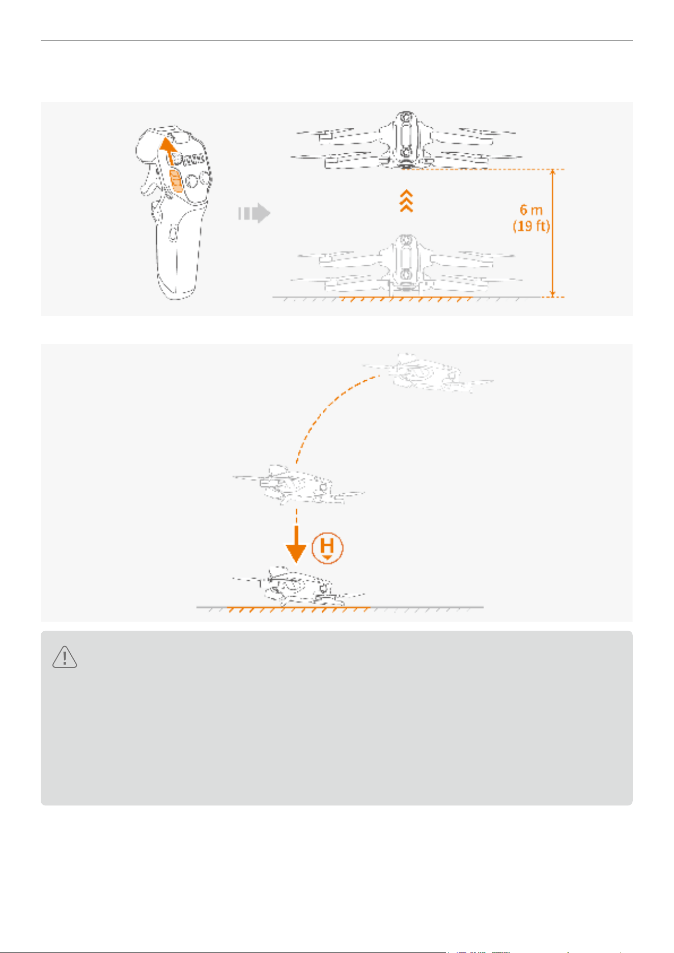
2. After the GNSS signals are obtained and the Home point is recorded, proceed to the takeoff operation. During
takeoff, you must ascend the drone vertically for at least 6 meters above the ground, and then y horizontally.
3. When executing RTH, the drone will then return and land at the Home point with high precision.
� The performance of Precision Landing is limited by the following conditions:
a. The home point must have been successfully recorded during takeoff and must not be changed during
the ight. Otherwise, the drone will not be able to land safely due to the terrain feature not matching.
b. During takeoff, the aircraft must rst ascend vertically at least 6 meters (19 ft) before ying horizontally.
c. The terrain features of the Home point must remain largely unchanged.
d. The terrain features of the Home point must be sufciently distinct. The performance of Precision
Landing will be affected when ying in scenes such as snow-covered areas.
e. The lighting conditions near the Home point are too bright or too dark.
22
Antigravity A1 User Manual
©
2026 Antigravity All Rights Reserved
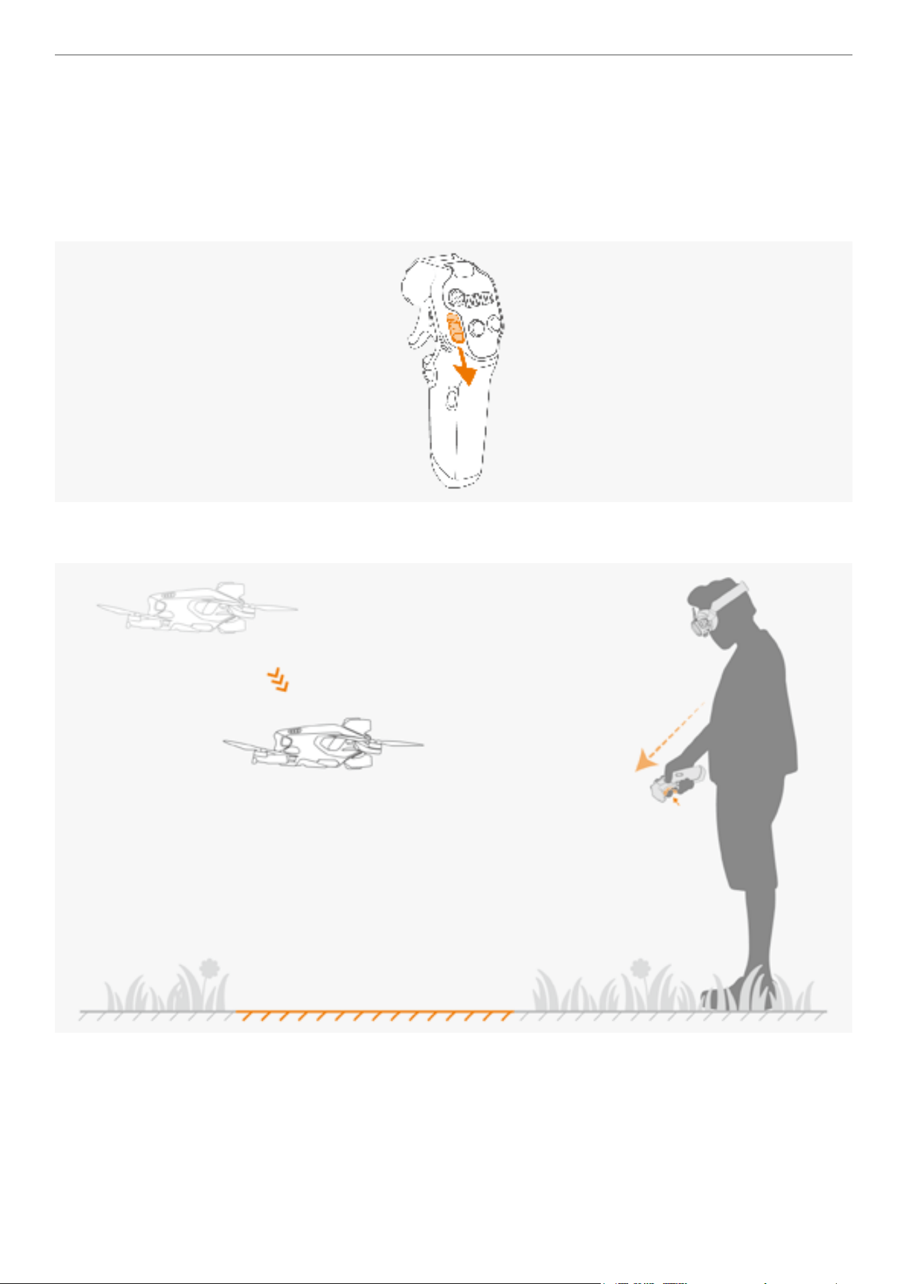
Manual Landing
1. In the absence of a strong GNSS signal, users can still manually control the drone to y back to the vicinity of the
return point.
2. Control the drone's movement and guide it to an open, at ground for landing. Release the throttle trigger of the
Grip Controller, then the drone will hover above the landing area.
3. Push the unlock slider downwards and then drone starts descending.
4. Tilt your line of sight downward to locate an suitable landing area when the drone is approaching the Home point.
Point the Grip Controller towards the landing area and hold onto the throttle trigger.
23
Antigravity A1 User Manual
©
2026 Antigravity All Rights Reserved
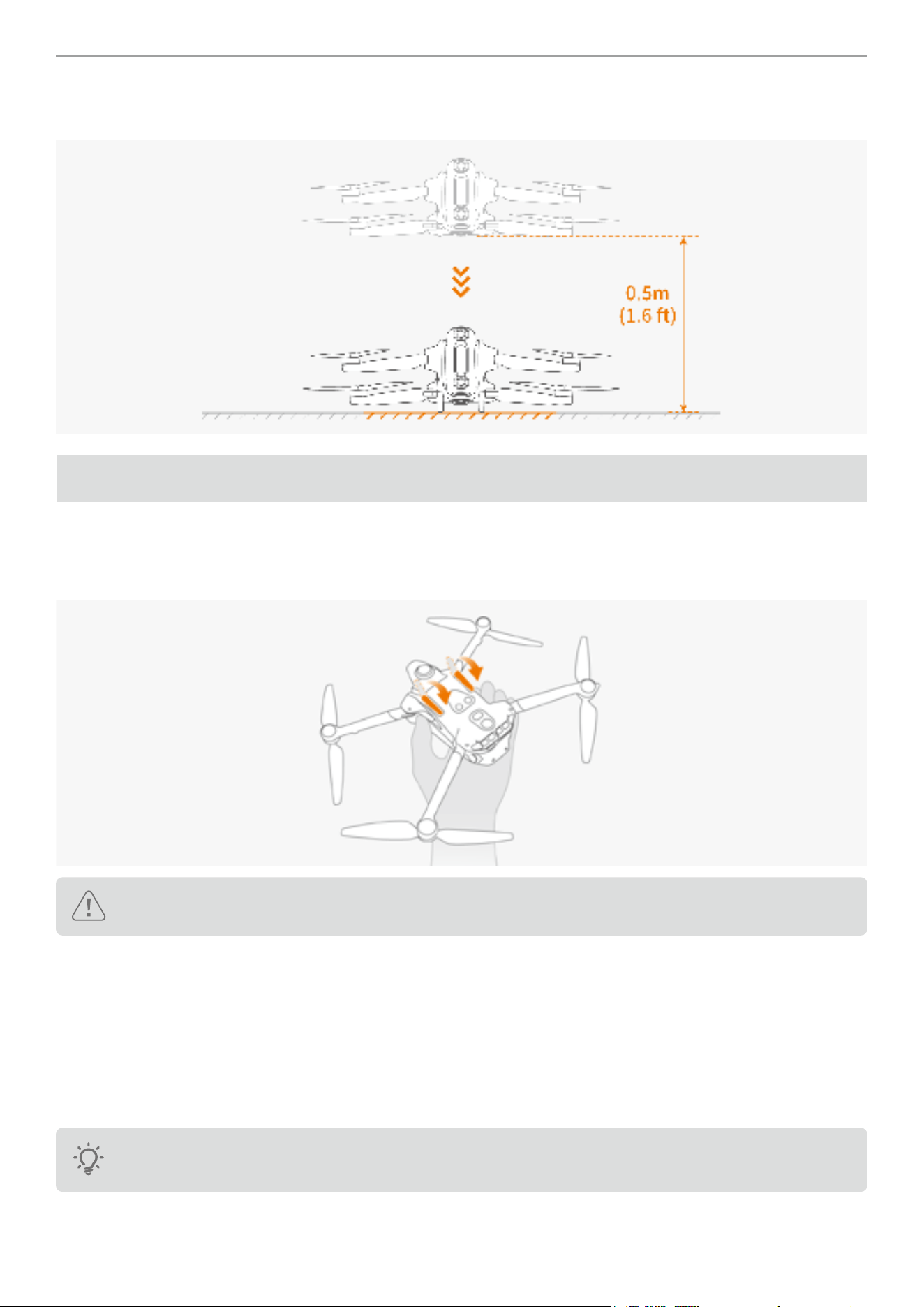
5. The drone descends to 0.5 meters (1.6 ft) above the ground. Continue pushing the slider downwards then the drone
will enter landing stage and the landing gear will automatically lowered and proceed to land.
Post Flight Check List
1. Inspect the ight battery and the propeller, ensure there is no visible damage.
2. Brush off the dirt and stains on the camera and sensor lenses by using the ofcial cleaning wipe.
3. Ensure the landing gear is retracted. Manually retract them if required.
Landing gear must be retracted; otherwise, you will not be able to place the drone into the storage case.
4. After powering off the drone, ensure that all four arms are folded.
5. After powering off the drone, ensure that the antennas on the Vision Goggles are folded.
6. Your ight battery will hibernate when stored for an extended period. Charging your battery at intervals is
recommended to allow the battery to exit from hibernation.
7. Store the drone, controller, batteries, and battery charger in a dry environment. The recommended storage and
transportation temperature range is between 15°C (59°F) to 25°C (77°F) with an approximate humidity of 40%. No
altitude restriction is imposed.
After using the drone in a humid or rainy environment with condensation, make sure to let it sit or dry at
low temperature before storing to prevent moisture from affecting the lens on the drone.

24
Antigravity A1 User Manual
©
2026 Antigravity All Rights Reserved
8. Before servicing the drone (such as cleaning or installing propellers), be sure to remove the battery rst. Use a soft
cloth and the ofcial lens cleaning cloth to remove any dirt or dust, ensuring the drone and propellers are clean. Do
not clean the drone with a wet cloth, and avoid using alcohol-based cleaners. Liquid may leak into the drone's shell,
causing a short circuit and damaging electronic components.
9. When replacing or inspecting the propellers, refer to the instructions in “Power On and Off” on page 50 to
power off the drone rst.
Flight Safety and Control
Flight Environments Requirements
1. Do not operate in severe weather conditions, such as strong winds (wind speed 10.7 m/s (23.2 mph)and above),
snow, rain, fog, and sandstorm etc.
2. Do not maneuver the drone in and out of the clouds, as it is dangerous and poses unpredictable risk.
3. Do not use the drone in high-temperature, ammable, and explosive environments.
4. Choose an open area with no tall buildings or structures nearby. As the presence of large amount of steel
reinforcement will affect the operation of the on-board compass and block GNSS signals, resulting in poor
positioning performance or even the inability to locate the drone. Therefore, do not take off on a balcony or within
10 m (32 ft) of a building, and it is recommended that you steer the drone at least 10 m (32 ft) away from buildings
during ight. When the drone approaches a building or highrises, it is recommended to exit from the automatic RTH
and land the drone manually in the nal phase of RTH.
5. When operating in high-altitude areas, due to environmental limitations, the performance of the battery and motors
will be impacted, and ight performance will be affected. Please y with caution. For the drone with the standard
ight battery, the maximum takeoff altitude is 4000 m (13,123 ft). For the drone with a high-capacity ight battery,
the maximum takeoff altitude is 3000 m (9,842 ft). When operating in high altitude areas, attaching the propeller
guard to the drone while using the high-capacity ight battery can noticeably reduce the drone’s performance, y
with caution.
6. The braking distance of the drone is affected by the altitude of the ight environment. The higher the altitude, the
greater the braking distance required. When operating in areas with an altitude greater than 3000 m (9,842 ft),
users should reserve at least 25 m (82 ft) of horizontal braking distance to ensure ight safety.
7. Maintain line-of-sight control, stay away from obstacles, crowds, water surfaces, and stay well above the water
surface.
8. Maintain safe altitude from the water surface or the ground when operating your drone.
9. Do not y in areas with high-voltage power lines, communication base stations, or transmission towers to avoid
transmission interference with the Grip Controller.
10. The GNSS positioning system is not operational for ights within the Arctic and Antarctic Circles. However, you can
still use the vision positioning system for stabilization.
11. Do not takeoff from the surface of moving platform (such as moving cars, boat deck etc.) or inclined surfaces.
When taking off, be sure to choose a stationary horizontal platform.
12. Do not take off on the surface of solid-colored objects or objects with strong reections and lack of distinct texture
(such as the roof of a car).
13. Operate the drone, remote controller, battery, and battery charging hub in a dry environment.
14. In the event of an act of God (such as global satellite failure, storms, lightning strikes, electromagnetic
interference), or other unforeseen circumstances, drones may not be able to perform their ight tasks as expected.
25
Antigravity A1 User Manual
©
2026 Antigravity All Rights Reserved
Flight Protection
Flight Protection Area
The ight protection system designates safe ying locations, provides ight risk assessment and safety tips for your
ights, and offers information on controlled airspace. Drone cannot take off from or y into the protection area, hence,
it is important survey the area before you attempt to operate your drone. Users can check if their locations are near the
ight protection zones using the Antigravity app. The system restricts takeoff and ight in areas that may pose safety
or security risk to others. For the policy regarding ight protection areas, visit the ofcial website
(https://www.antigravity.tech).
Flight Protection Map
The geographic information is available in the Antigravity app. View this information from the built-in map of the
Antigravity app before each ight. You should conrm that the planned take-off spot is not within or adjacent to a ight
protection area. Otherwise, you will not be able to y your drone near the planned take-off spot. Users can also use
the ofine map function of the Vision Goggles to browse the location of these ight protection areas.
Flight Altitude and Distance Restriction
Flight Restriction
A ight restriction is set by default in order safeguard the safety of users and general public. This section will provide
information about how to cong the ight restriction.
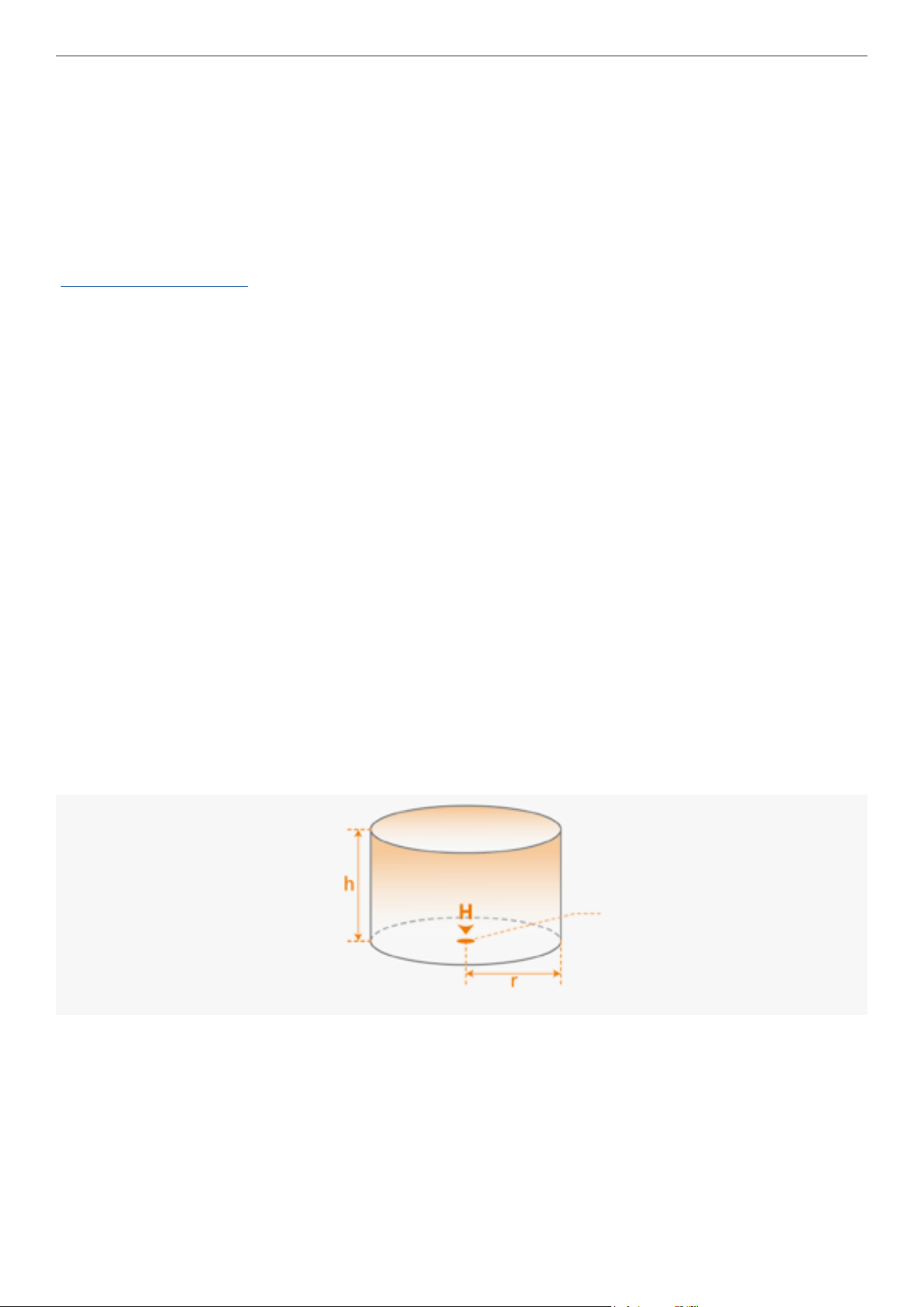
You can set the ight altitude and distance restrictions from the Vision Goggles menu. Once you have completed the
setting of the restriction values, a virtual cylinder that comprises ight altitude, distance, will be in effect to restrict
where the drone can y. If the GNSS system is not operational, the ight distance restriction is disabled, but only the
ight altitude is restricted.
Flight Altitude and Flight Distance Restriction
� Strong GNSS Signal
The maximum altitude is the maximum height of the drone measured from the take off point, and the maximum
distance determines the farthest ying distance of the drone from the Home point. Users can set these two values in
the Vision Goggles.
Max altitude
Home point
Max distance
26
Antigravity A1 User Manual
©
2026 Antigravity All Rights Reserved
� Weak GNSS Signal
The maximum altitude of the drone will be affected by factors such as ambient light, particularly when the GNSS signal
is weak.
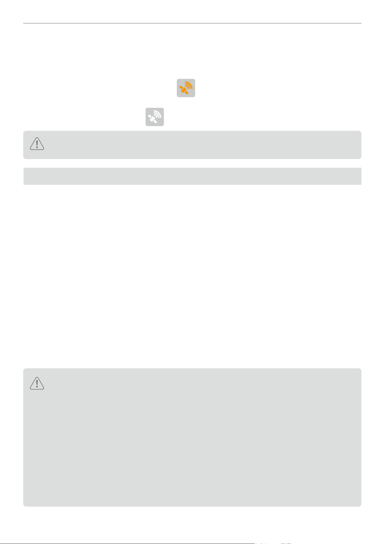
- When the ambient light is normal and the GNSS signal is strong, the maximum altitude is around 10 m (32 ft). In
the event of the GNSS signal resuming to yellow (
), the restriction on the ight altitude will be lifted.
- When the ambient light is dim and the GNSS signal is weak, the maximum altitude is around 2 m (6 ft). In the event
of the GNSS signal resuming to white (
), the restriction on the ight altitude will be lifted.
It is possible that the drone will y beyond the restricted ight range due to inertia. The user can still
control drones in this instance. However, you should control your drone to y back into the safe area.
Flight Safety Best Practice
Follow the best practices below to avoid serious personal injury or causing property damage.
1. Ensure that you are not under the inuence of anesthesia, alcohol, or drugs, and do not experience dizziness,
fatigue, nausea, or any other conditions that may affect the safe operation of the drone.
2. When landing, rst turn off the drone's power, then turn off the remote controller.
3. It is strictly prohibited to throw, launch, or otherwise project any dangerous payload towards any buildings,
individuals, or animals to prevent personal injury or property damage.
4. Do not use a drone that has been involved in a collision, accident, or is in poor condition.
5. Ensure adequate training and establish emergency plans for emergencies or accidents.
6. Develop a ight plan and avoid reckless driving of the drone.
7. When using the lming function, respect the privacy of others and ensure compliance with local privacy laws,
regulations, and ethical standards.
8. This product should only be used for general personal use, and not for any other purposes.
9. Do not use it for illegal or improper purposes, such as espionage, military operations, or unauthorized investigations.
10. Do not use this product to defame, insult, harass, track, threaten others, or in any other way infringe on the
legitimate rights such as privacy rights and publicity rights of others.
11. Do not use the drone to trespass into others' private property.
� Do not approach the rotating propellers or motors. Do not attempt to catch the drone while it is hovering
in the air by hands, and do not attempt to hold the drone in the palm of your hand for takeoff or landing
operations.
� Before takeoff, ensure that all devices are fully charged and that there is no visual damage or cracks to
the propellers.
� Familiarize yourself with each ight mode by reading the ofcial user documentation or watching videos
tutorials, and understand the return-to-home procedure.
� Upon receiving the low battery warning from the device, user shall immediately return the drone to its
home point.
� During automatic RTH, adjust the ight speed if required for a safe landing.
� Ensure the connection between the Vision Goggles and the battery is secure at all times; otherwise, it
may cause disruption while in use.

27
Antigravity A1 User Manual
©
2026 Antigravity All Rights Reserved
RTH and Obstacle Avoidance Safety Notice
Return to Home (RTH)
� During the RTH, your drone will automatically adjust its ight speed to account for external factors such
as wind speed and obstacles, making necessary changes of heading to navigate around obstacles on its
ight path.
� The accuracy of the RTH is dependent on GNSS signal strength. Hence, if the GNSS signal is interfered
with, your drone may not be able to y back to its recorded Home point.
� If possible, only activate the RTH in an open area as the obstacle avoidance sensors cannot detect small
objects like branches or power lines while the RTH is in process.
� Set the RTH altitude higher than all surrounding visible structures before the ight if there are power lines
or tall towers along the RTH path.
� During the RTH process, the Home point, RTH altitude, and RTH behavior cannot be updated from the
Vision Goggles. It is important to set appropriate RTH parameters before taking off your drone.
� If the refreshed maximum altitude is set below the current altitude during the RTH process, the drone will
rst descend to the newly set maximum altitude and then continue the ight.
� The RTH altitude cannot be changed during the RTH process.
� If there is a signicant deviation between the current altitude and the preset RTH altitude, it is likely that
the drone cannot accurately estimate the power consumption due to different wind speeds at different
altitudes. Pay extra attention to the diminishing battery level and warning messages on the Vision
Goggles in this scenario.
� In the RTH process, if the drone reaches the maximum ight altitude during ascent, the drone will stop
ascending and return to the Home point at the current altitude. Pay attention to ight safety during the
RTH process.
� If the recorded Home point is in a altitude restricted area but the drone is not in that area during the RTH,
then when the drone entered the altitude restriction area, it will rst descend to comply with altitude
restriction, which may be lower than the pre-set RTH altitude. Fly with caution.
� During the RTH process, the drone will avoid any ight protection areas while ying forward. Fly with
caution.
� The drone will abort the RTH if it fails to determine whether it is safe to y when the surrounding area is
too complex.
� Before each ight, set the appropriate RTH altitude based on the surrounding environment. Enter the
settings menu on the Vision Goggles and set the RTH altitude. The default RTH altitude is 110 m (360 ft).
� If obstacle avoidance system become unavailable, it is advised that users to regain control and manually
land the drone.
� Flight protection areas may affect the ight path of drone during the RTH. Avoid ying near ight
protection areas.
� The drone may not be able to return to the Home point in the strong wind environment. Fly with caution.
� During the RTH, pay extra attention to small objects (such as branches or power lines) or transparent
objects (such as water or glass). In emergency , abort the RTH and manually land the drone.
28
Antigravity A1 User Manual
©
2026 Antigravity All Rights Reserved
Obstacle Avoidance Safety Notice
Be aware of the surroundings of the ight site at all times. Since the performance of the obstacle avoidance system is
affected by ambient lights and other factors and cannot replace manual control and judgment, stay alert to the drone’s
movements during the ight. Do not solely rely on the obstacle avoidance feature when operating in the one of the
scenarios (tree braces, power lines, water surface, after sunset).
For more comprehensive information about the safety guidelines for using the obstacle avoidance feature. Refer to the
“Obstacle Avoidance” on page 44.
How to Control Your Drone
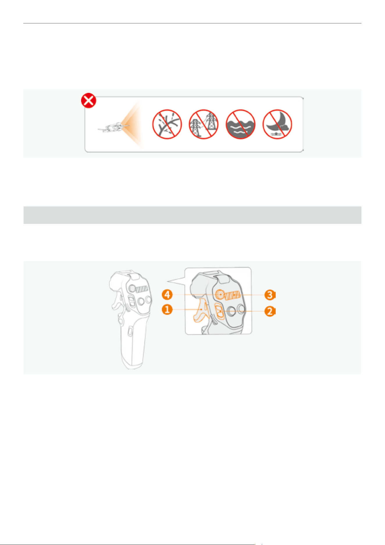
Basic Operations
Use the combination of
❶
throttle trigger,
❷
ight slider,
❸
360 dial view, and
❹
emergency brake/RTH button on the
Grip Motion Controller to control the attitude and ight speed of the drone, and adjust the orientation of the drone by
swinging the Grip Motion Controller.
29
Antigravity A1 User Manual
©
2026 Antigravity All Rights Reserved
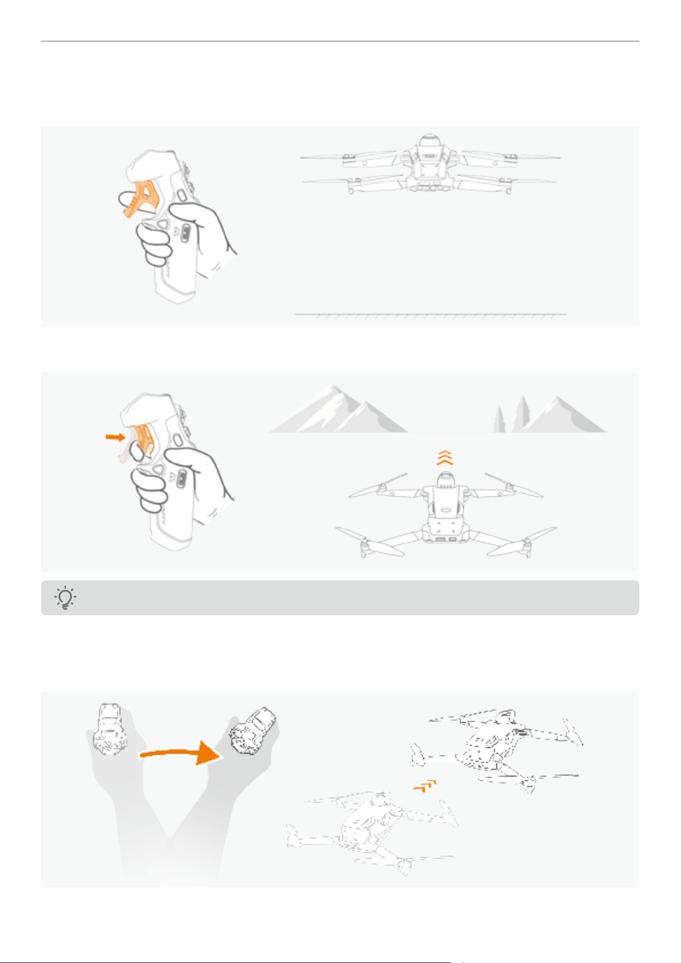
Horizontal Flight
Use the throttle trigger on the Grip Motion Controller to control the drone's horizontal speed.
� When the throttle trigger is released, the drone hovers at the current altitude.
� Push throttle trigger inward will make the drone y in the direction of the current heading. Greater throttle push allows
for faster acceleration.
The Antigravity A1 drone does not y backward.
Adjusting Heading of the Drone
Swinging your arm to the left or right controls the drone's heading in the Free Motion mode by default.
� Pressing the throttle trigger and swinging to the right will allow the drone y forward to the right.
30
Antigravity A1 User Manual
©
2026 Antigravity All Rights Reserved
� Pressing the throttle trigger and swinging to the left will allow the drone y forward to the left.
However, in the FPV mode, the heading of the drone is controlled by the rotation of the wrist rather than arm swing
movement. For more information about the control modes, please refer to the section “Controlling in FPV Mode” on
page 33.
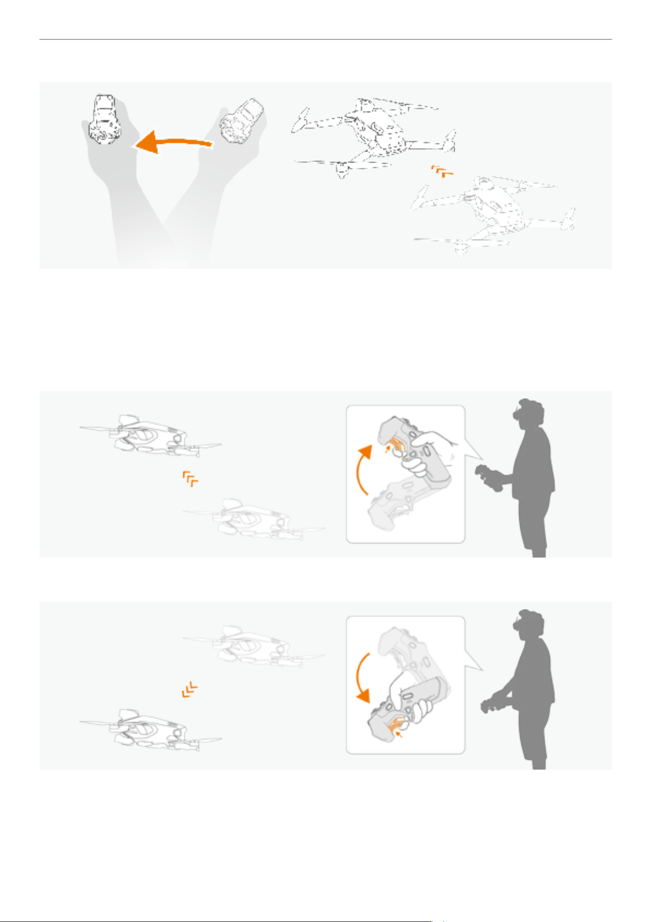
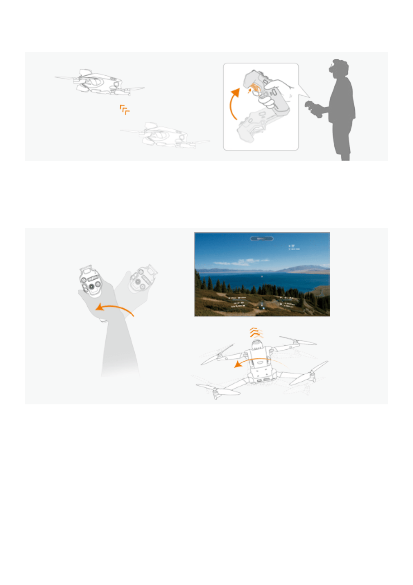
Climbing and Diving
� Using the wrist as the pivot, rotate the Grip Motion Controller clockwise toward the body to make the drone climb
upwards.
� Using the wrist as the pivot, rotate the Grip Motion Controller counterclockwise toward the body to make the drone
dive downwards.
31
Antigravity A1 User Manual
©
2026 Antigravity All Rights Reserved
Taking Off and Landing
Take off
� Push the ight slider in two short bursts to unlock the motors. The drone enters idle state with all four
motors unlocked and is ready to take off.
� Slowly push the ight slider upwards. The drone will start ascending and hover at 1.2 meters (3.9
feet).
Landing Push the ight slider downwards to allow the drone to descend gradually.
Brake
Press once on the emergency brake / RTH button to halt the drone from continues its ight. Press and
hold the same button again to resume the ight.
For safety, stop the drone before adjusting the tting of your Vision Goggles during ight to prevent
accidents.
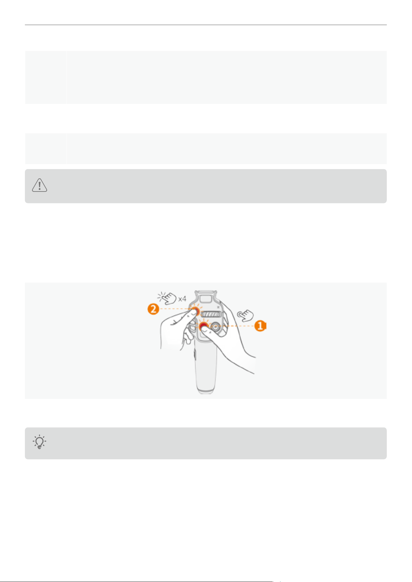
Stopping the Motors Mid-air
During the ight, if you encountered an emergency situation (such as the drone becoming uncontrollable), users can
trigger the mid-air motor stop by following button combinations:
1. First, press and hold the video recording button on the Grip Motion Controller.
2. While holding the video button, use the other hand to rapidly press the emergency brake/return-to-home (RTH)
button four times.
3. The motors will immediately shut down and the drone will fall from its current altitude. Be extra cautious when
exercising this option.
To use the mid-air motor stop function, you must rst enable this option in the Safety menu on the Vision
Goggles.
32
Antigravity A1 User Manual
©
2026 Antigravity All Rights Reserved
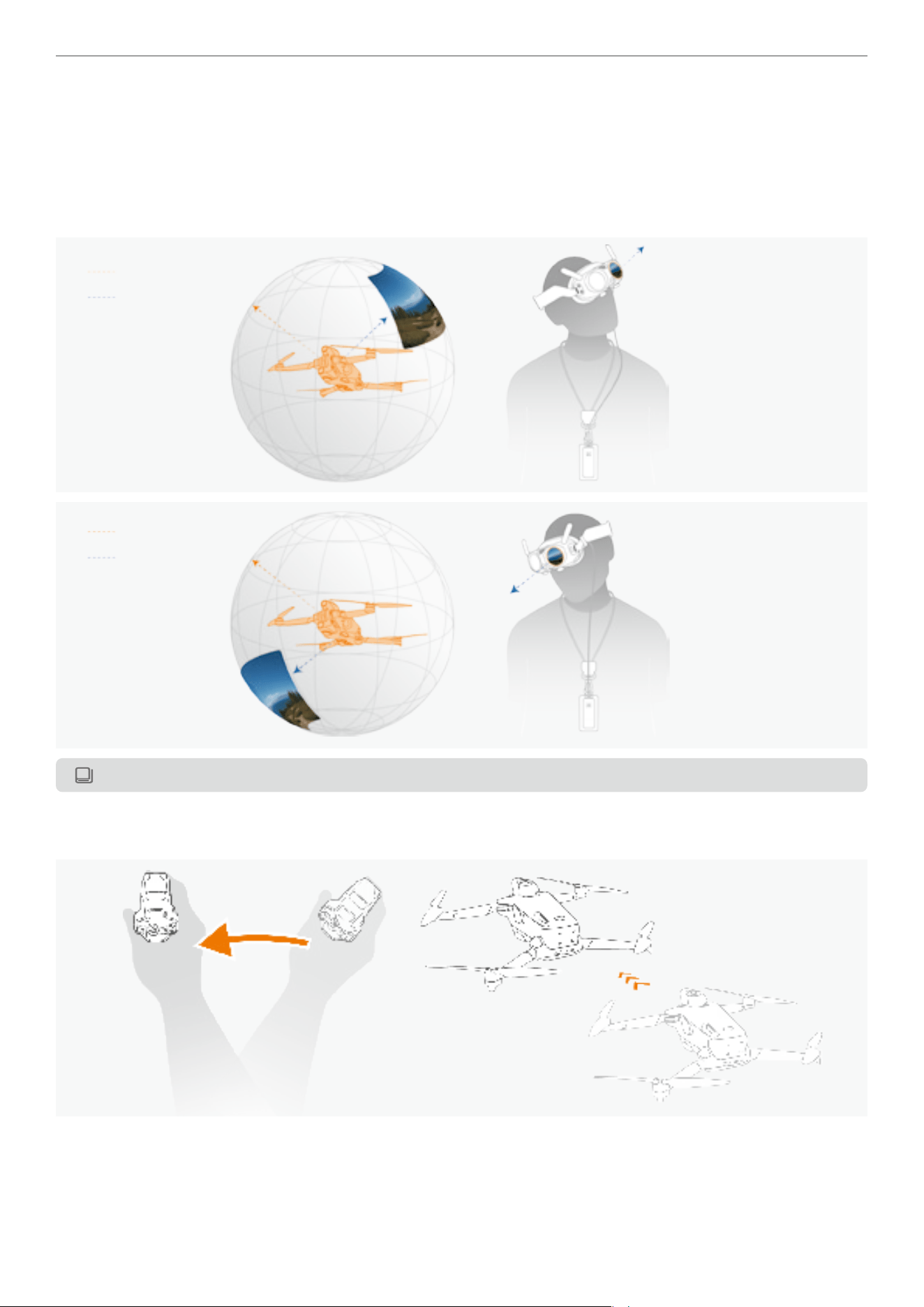
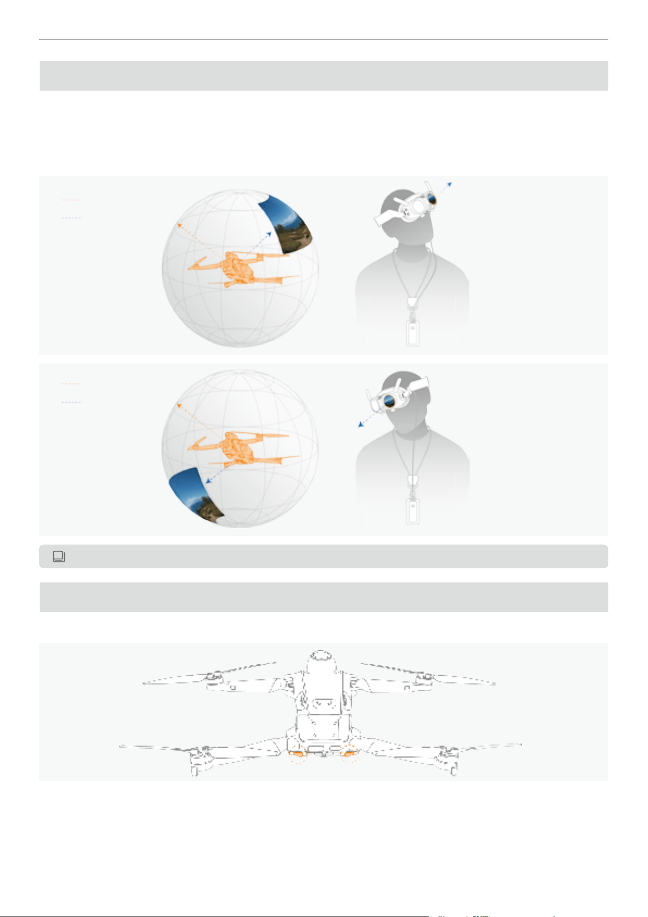
Controlling in Free Motion Mode
The Free Motion mode in the Vision Goggles allows for intuitive control of the drone using the Grip Motion Controller.
In this mode, the movement of the Grip Motion Controller syncs with the navigation point in the Vision Goggles,
directing the drone's heading. You can then observe a 360-degree free view during ight. When the viewpoint is
independent from the ight direction, a small picture-in-picture (PIP)window will pop up in the Vision Goggles will
display the front view of the drone.
Flight Direction
Head Tracking*
Flight Direction
Head Tracking*
*Head tracking syncs live view with the head movements from user, and it is independent of drone's heading.
In the Free Motion mode, the drone's heading will move with the navigation point.
� Swing the motion controller to the left with the pressed throttle, the drone's heading will also turn to the left.
33
Antigravity A1 User Manual
©
2026 Antigravity All Rights Reserved
� Tilt your arm upwards while press the throttle trigger, the drone will climb towards the navigation point.
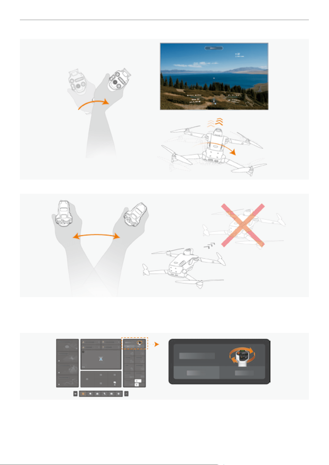
Controlling in FPV Mode
In FPV mode, the live view is aligned with the heading of the drone but not the head tracking perspectives. Turning
your head will not result in a change of the heading of the drone. However, you can still perform a 360 panoramic view
mid-ight. The biggest difference to Free Motion and FPV mode is the response to wrist movements.
� Rotating your wrist counterclockwise will cause the drone to turn left.
34
Antigravity A1 User Manual
©
2026 Antigravity All Rights Reserved
� Rotating your wrist clockwise will cause the drone to turn right.
left.
� In FPV mode, swinging your arms horizontally will not affect the heading of your drone.
Switching Between Control Mode
To switch between Free Motion and FPV mode, click on the icon at the top right of the Vision Goggles menu. The
drone will automatically switch to Free Motion mode upon engaging the RTH procedure.
35
Antigravity A1 User Manual
©
2026 Antigravity All Rights Reserved
A1 Drone
Flight Mode
The A1 drone offers three ight modes, which can be switched by toggling the button on the Grip Motion Controller.
The differences between these three modes are listed as follows:
� Normal (N) mode: The drone hovers accurately and maintains stable ight, suitable for most ight scenarios.
� Sport (S) mode: The drone ies at its maximum horizontal speed, with enhanced ight performance.
� Cinematic (C) mode: The horizontal speed is reduced compared to Normal mode, making it more suitable for the
professionals to capture smooth footage.
The location of the mode button is as follows, with the N mode set as default.
For information on the maximum speed in each of the ight modes, refer to the “Product Specication”
on page 89 in the appendix.
� Allow a minimum braking distance of 10 m (32.8 ft) for safety when ying in Sport or Normal mode in
windless environment.
� In Sport mode, the drone's speed increases signicantly compared to Normal mode, requiring a vertical
braking distance of at least 20 m (65 ft) in windless conditions for safety.
� The braking distance of your drone is affected by the ight altitude. When operating in high altitude
1
areas, allow for ample braking distance.
� In Sport mode, the drone's control sensitivity increases, so users should allow ample space for executing
any maneuvers.
� In Sport mode, the obstacle avoidance system is turned off automatically due to the increased speed.
Caution is advised.
When the vision system is unavailable or disabled, and the Global Navigation Satellite System (GNSS) signal is weak
or the compass is interfered with, the drone will automatically switch to Attitude (ATTI) mode. In Attitude (ATTI) mode,
the drone may be more susceptible to the inuence of the surrounding environment. In this scenario, even a mild wind
may cause the drone to drift, which is dangerous when ying indoors or in narrow spaces. It is recommended to land
the drone immediately to avoid accidents when the drone in this mode.
1
With a high-capacity ight battery, high-altitude areas are dened as above 3000 meters. When equipped with a standard battery, high-altitude areas are dened as
above 4000 meters.
36
Antigravity A1 User Manual
©
2026 Antigravity All Rights Reserved
Controlling Mode
FreeMotion Mode
In the FreeMotion mode, the navigation point is constantly tracking with the your movement or gestures, allowing the
drone to sync its direction with the navigation point. This enables a 360-degree view during ight, with a PIP windows
displaying the drone's front view. For more information, refer to “Controlling in Free Motion Mode” on page 32.
Flight Direction
Head Tracking*
Flight Direction
Head Tracking*
*Head tracking syncs live view with the head movements from user, and it is independent of drone's heading.
Flight Indicators
The ight indicators locate the rear of the A1 drone. Refer to the gure below:
37
Antigravity A1 User Manual
©
2026 Antigravity All Rights Reserved
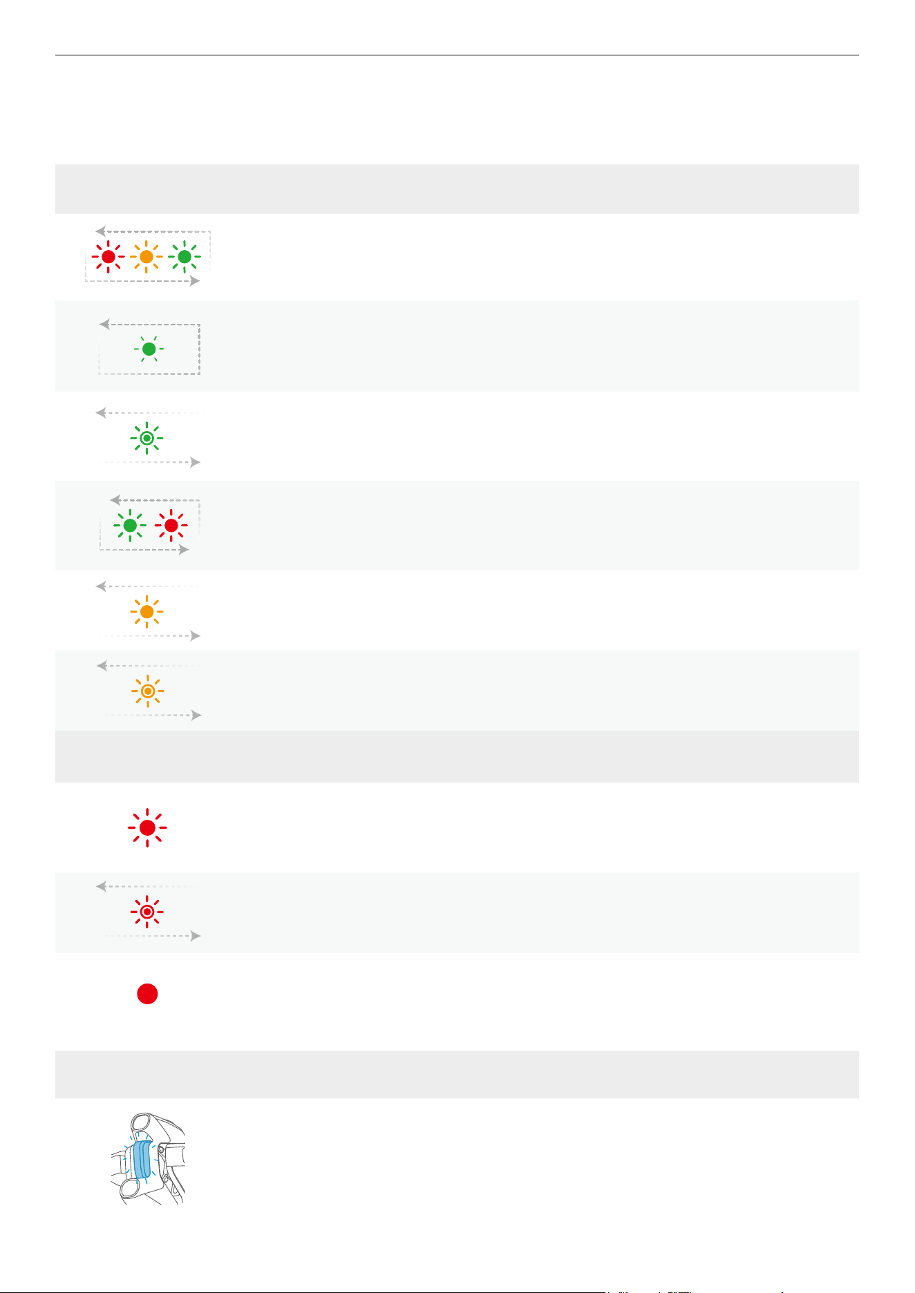
Before Taking Off
After the drone's power is turned on and the motors are not yet started, the blinking ight indicator LED will show the
current system status. Refer to the table below for the explanation of each blinking pattern.
General Status
Alternating blinking of red,
orange, and green LEDs
Drone self-check.
Slow blinking of green LEDs
Strong GNSS signal detected. The drone is ready to
take off.
Slow burst of blinking green
LEDs
No GNSS is available but only Vision sensing system is
available. The drone is ready to take off.
Alternating blinking of red
and green LEDs
Motors are unlocked and the propellers start rotating.
The drone is ready to take off.
Rapid blinking of yellow Connection signal lost between the drone and controller.
Short burst of blinking yellow Battery level low.
Critical Status
Blinking red LEDs
� System error detected.
� Drone is in ATTI mode. (no GNSS signal detected and
vision system is not available)
Blink twice in red over a
short burst.
Critical low battery level. Land your drone immediately.
Solid red LEDs
Critical system error detected. Power on and off your
drone.
Front Indicator Pattern Drone Status
Blinking blue LED Firmware update in progress.
38
Antigravity A1 User Manual
©
2026 Antigravity All Rights Reserved
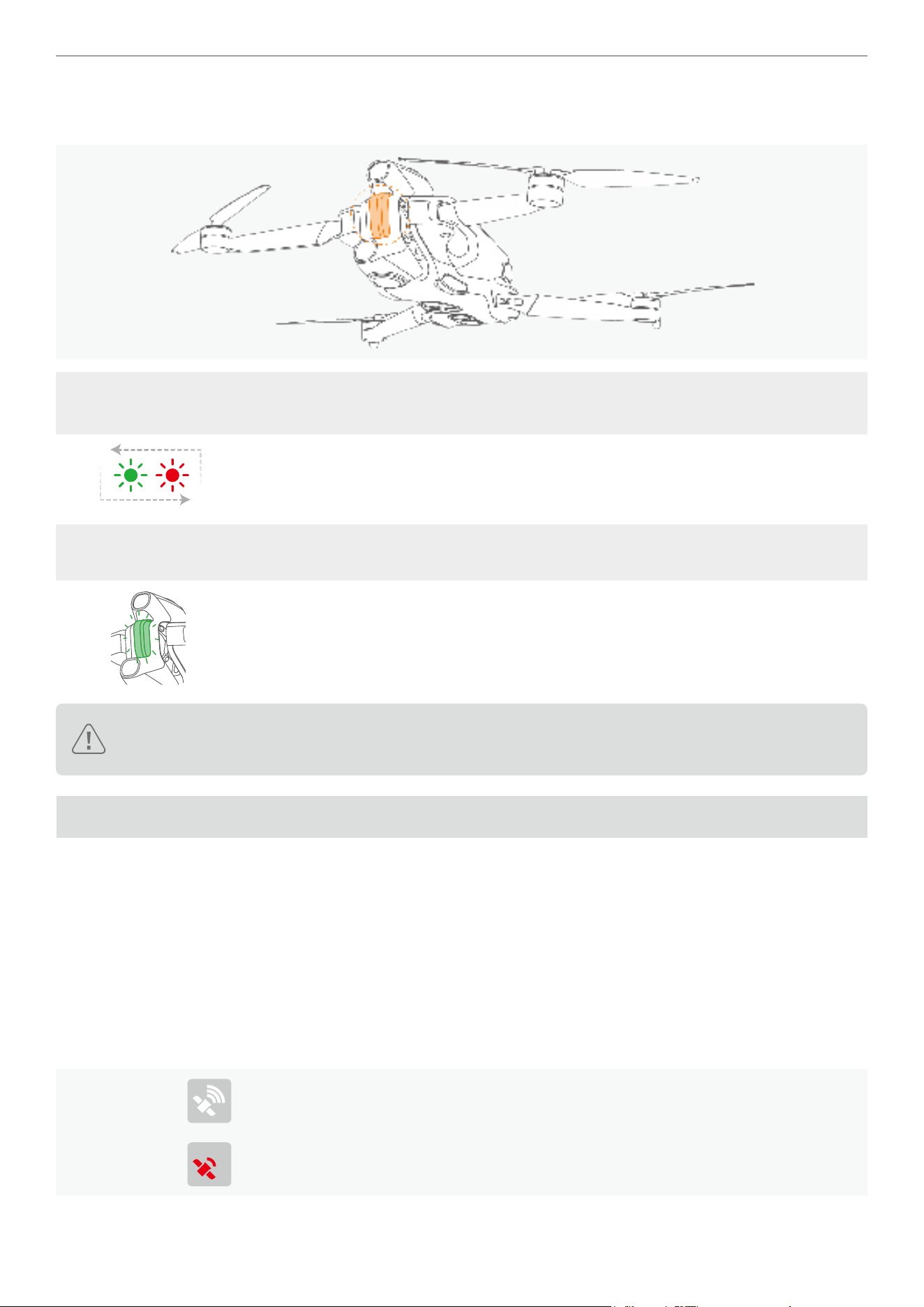
After Take-off
While the drone has taken off, the ight indicator at the front will start blinking green.
Flight Indicators at
Rear
Pattern Drone Status
Alternating blinking of red
and green LEDs
Normal. Drone is in ight.
Front Indicator Pattern Drone Status
Slow blinking of green LED Normal. Drone is in ight.
The blinking pattern of the ight indicator may vary by country or region. Please comply with local laws
and regulations.
Return to Home (RTH)
Introduction to RTH
The RTH function allows the drone to return to the last recorded home point on its own. There are three ways to
initiate RTH: manual activation, low battery, or loss of control signal. If the drone has successfully recorded the home
point and the GNSS is working properly, the drone will automatically return and land at the home point.
Home Point
Home point is dened as the location where a strong to medium GNSS signal strength (represented by a white icon)
is received. So long as the signal strength remains stable before takeoff, the Home point can be refreshed. However, If
the signal is weak, the Home point will not be updated.
GNSS Signal
White icon denotes strong GNSS signal, the Home point is recorded and can be
updated.
Red icon denotes weak GNSS signal, the Home point cannot be recorded or updated.
39
Antigravity A1 User Manual
©
2026 Antigravity All Rights Reserved
Home Point
It can be either automatically or manually updated when the GNSS signal is normal.
Caution: If the drone is adjacent to, or within a ight protection area, the
Home point cannot be refreshed or recorded.
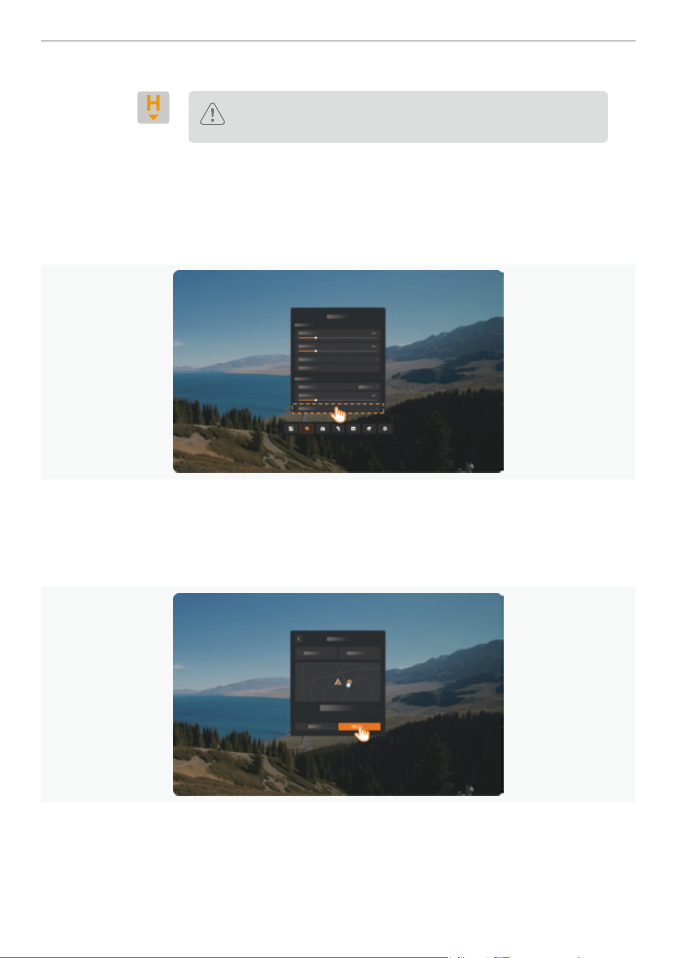
Updating Home Point
Users can manually update the Home Point if the GNSS signal is strong. Follow the instructions below to manually
refresh the Home Point.
1. Press once on the Menu button of the Motion Controller.
2. Navigate to the update home point option via: “Safety Setting” -> “Update Home Point”.
3. Select Home Point source location:
a. Drone Position: Sets Home Point the drone’s current location.
b. Remote Controller Position: Sets Home Point to the Remote Controller’s location (typically associated with the
user’s location).
c. Click “Update” to conrm the settings.
40
Antigravity A1 User Manual
©
2026 Antigravity All Rights Reserved
4. A ‘Home Point Updated’ text prompt will appear in the lower-right corner of the Vision Goggles display. If Home
Point was updated successfully.
The remaining battery level estimation is subject to change when the Home Point is updated to a new
location, as the Return to Home (RTH) distance will be affected. Users should remain vigilant about the
latest battery level of the drone whenever the Home Point is being updated, and should start the RTH if
necessary. Failure to do so may result in the drone not being able to y back to the newly updated Home
Point.
RTH Process Breakdown
1. Home point is successfully recorded.
2. Start RTH. Activating the RTH can be set in the RTH settings.
� The RTH can be triggered by the following use cases:
- Manually initiating RTH.
- Automatically when the control signal is lost between the drone and controller.
- Automatically triggered when the battery level is critically low.
� The default RTH behavior is return to the Home point, however, it can also be set as hover.
3. During RTH, users can abort the RTH ight by short-pressing the RTH button on the Grip Motion Controller.
41
Antigravity A1 User Manual
©
2026 Antigravity All Rights Reserved
4. When the drone is in the horizontal RTH phase, users can pull the throttle trigger to accelerate the drone and guide
the drone quickly to the safe landing area.
5. The ight altitude is crucial for correctly guiding the drone back, so the drone will adjust its ight altitude based on its
distance from the Home point:
� When the drone is less than 5 m (16 ft) from the Home point, the drone will land from its current altitude.
� If the drone is within 5 to 50 m (16 ft to 164 ft) from the Home point, it will return at the current ight
altitude. If the RTH altitude is less than 3 m (9 ft), the drone will rst climb to 3 m (9 ft) before ying to the
Home point.
� If the drone is more than 50 m (164 ft) from the Home point and its current altitude is lower than the
preset RTH altitude, it will rst climb to the preset RTH altitude before ying back. If the current altitude is
already higher than the preset RTH altitude, it will y back at the current altitude.
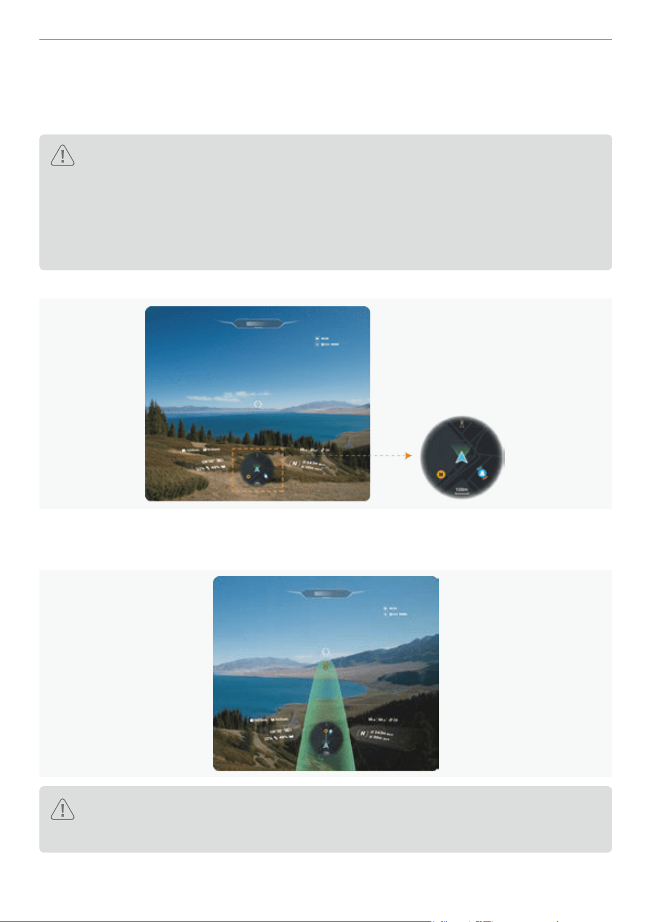
6. During the RTH process, users can view the drone's ight path on the mini-map in the Vision Goggles.
7. During the RTH process, a green AR ight path will be projected on the Vision Goggles, indicating the estimated
ight path from the current position to the Home point. Users can utilize the ight path to identify if there are high
rises or obstacles on the RTH ight path, and regain control of the drone if necessary.
When obstacle avoidance is enabled, the drone will analyze real-time data during the RTH ight and select
the safest ight path. It will automatically adjust its heading and navigate around the obstacle if possible,
ensuring a secure and reliable return.
8. Upon reaching the Home point, the drone will land automatically and the motors will stop.
42
Antigravity A1 User Manual
©
2026 Antigravity All Rights Reserved
Manually Initiating RTH
During the ight, users can initiate the return to home function by long-pressing the emergency brake/return button.
RTH Triggered by Low Battery Level
1. To prevent the drone from being unable to return to a safe location due to low battery power, if the drone detects
that the current battery level is insufcient to y back to the Home point, the drone will automatically trigger the RTH
on its own.
2. During the ight, the drone will analyze in real time whether the current battery level supports a safe return. If it
detects that the remaining mileage is not sufcient to return to the home point, it will issue a low battery countdown
reminder and initiate a 10-second countdown. If there is no user action within the 10-second countdown, the drone
will return automatically.
3. If the drone detects that the remaining mileage is not sufcient to support the landing, it will issue a critical low
battery countdown reminder on the Vision Goggles and initiate a 10-second countdown. If there is no user action
within the 10-second countdown, the drone will land from the current position automatically.
� In strong wind conditions, the estimation of remaining ight distance may be affected.
� If the current status of the drone does not support the estimation of remaining ight distance (e.g., no
home point, battery communication abnormality, no GNSS signal), the estimation of remaining ight
distance will be invalid, and users need to pay attention to ight distance and battery level.
� Users can still use the Grip Controller to guide the drone towards an appropriate landing site during the
automatic landing.
RTH Triggered by Loss of Signal
When the video transmission signal of the Vision Goggles or the Grip Motion Controller is lost, if the Home point has
been successfully set, then the RTH process be activated automatically if the signal loss timeout occurs.
� If the Lost Connection Behavior is set to “Hover,” the drone will hover when the RTH is triggered and
remain hovering until the battery is depleted. When the low battery RTH is triggered, the drone will
return to its Home point automatically. The user can regain control of the drone if necessary.
43
Antigravity A1 User Manual
©
2026 Antigravity All Rights Reserved
RTH Flight Maneuver Strategies
The following ight maneuvers will be carried out when the RTH is activated either manually or automatically. The
purpose of such maneuvers is to maximize the chance of avoiding obstacles on the ight path for the RTH, so that
your drone will return to the Home point safely.
� Activate Path Seeking
Should the drone found itself in an narrow and complex environment that prevents it from engaging a safe return to
the Home point. The drone will attempt to maneuver itself to an open area to proceed with the RTH procedure.
� Flight Path Back Track
If the RTH is triggered due to the loss of control signals, the drone will adjust its ight course and back track the ight
distance of 90 meters, and then start returning to the Home Point at the pre-set RTH altitude.
� RTH Altitude Automatic Adjustment
During the RTH, the drone will try to automatically avoid obstacles. If the drone senses there is an obstacle on the
ight path, the drone will automatically climb up in order to by pass the obstacle and then resume its ight path. If the
drone detects an obstacle underneath, it will also adjust its ight altitudes.
The above mentioned altitude adjustments will only be activated when in an ideal light conditions.
� RTH in Flight Protection Areas
If the RTH ight path crosses a ight protection area, the drone will attempt to by pass and circumvent the ight
protection area and continue its RTH ight path.
By-pass the ight protection areas will increase the RTH ight distance, which may affect the safe return
of your drone. In order to maximizing the chance bring your drone back to the Home point, stay away
from the ight protection areas.
RTH Risk Notice
� In strong wind conditions, the estimation of remaining ight distance may be affected.
� If the current status of the drone does not support the estimation of remaining ight distance (e.g., no
home point, battery communication abnormality, no GNSS signal), the estimation of remaining ight
distance will be invalid, and users need to pay attention to ight distance and battery level.
� When triggering RTH in a low-lit environment, the performance of the obstacle avoidance system will be
signicantly degraded, and the drone may not be able to sense obstacles on the ight path. Users should
exercise caution and be prepared to take control of the drone when necessary.
Obstacle Avoidance and Landing
Obstacle Avoidance Overview
The drone is equipped with a dual-camera vision system for forward and downward sensing, providing multi-directional
obstacle avoidance support for its ight.
� Direction: The drone has obstacle avoidance capability in the forward and downward directions. The forward
obstacle avoidance system detects obstacles in front of the drone to ensure safety during forward
ight; the downward obstacle avoidance system is used to detect obstacles beneath the drone,
assisting in avoiding ground or other objects during take-off, landing, and low-altitude ight.
� Forward : The effective distance of forward obstacle avoidance varies in different scenarios and conditions.
Generally, the forward ranging distance is between 0.5 meters and 18 meters.

44
Antigravity A1 User Manual
©
2026 Antigravity All Rights Reserved
� Downward: The downward ranging distance is between 0.3 meters and 7.5 meters, effectively detecting obstacles
below the drone to ensure the safety of low-altitude ight.
Obstacle Avoidance
The obstacle avoidance feature relies on multiple systems such as the vision system and infrared sensing system on
the drone. Users must understand safety precautions when using this function. Observe the following practice when
using the obstacle avoidance feature.
� Be aware of the surroundings of the ight site at all times. Since the performance of the obstacle
avoidance system is affected by ambient lights and other factors and cannot replace manual control and
judgment, stay alert to the drone’s movements during the ight.
� When the GNSS signal is weak and the drone is ying at 0.3 to 7.5 meters (1.0 to 24.6 feet). The
downward vision system works best in this range. If the drone ies higher than 10 meters (32.8 feet),
vision positioning may be degraded. Fly with caution.
� In dimly lit environments, even with the landing light turned on, the vision system may still not achieve
optimal performance, hence the user should y with caution.
� When ying near the water surface, the downward vision sensor system may not work properly. This
could make it challenging to avoid the water surface during landing. It is important to maintain control of
the drone, assess the surroundings, and not rely too much on the vision system for stabilization.
� The vision sensors cannot identify large structures with frames and wires, such as tower cranes, high-
voltage transmission towers, high-voltage power lines, cable-stayed bridges, and suspension bridges.
Do not operate near these structures.
� The vision sensors may not work effectively near surfaces with no distinct patterns, or in areas with low
or high lighting. Exercise caution when operating your drone in the following scenarios:
a. Flying over the monochrome surfaces.
b. Flying over the highly reective surfaces.
c. Hovering or y over the water or transparent surfaces.
d. Landing on the moving surfaces or objects.
e. Flying over areas with drastic changes in light.
f. Flying over extremely dark or bright surfaces.
g. Flying over reective surfaces or surfaces that absorb infrared waves, such as mirrors.
h. Flying over surfaces with no distinct pattern or texture.
i. Flying over surfaces with repetitive identical patterns or textures, such as tiled designs.
j. Flying into obstacles with small reective surfaces, such as branches or power lines.
� Keep the camera and sensors clean. Keep the lenses away from scratches. Do not attempt to modify
the lenses. Do not use the drone in dusty or humid environments.
� Do not y on rainy or foggy days, or when low visibility conditions.
� Before each takeoff, ensure to check the following items:
a. Make sure there are no stickers or stains on the sensors of the infrared and vision systems.
b. Clean the sensors of the vision and infrared system. Remove any residue such as dirt, dust, or
water. Use a dry cloth for cleaning and avoid alcohol-based lotions as a cleaning agent.
� Remain vigilant and y with caution when operating your drone at night, as the vision system is
not available in low light conditions and the drone may not be able to avoid obstacles or hover with
precision.
� Performing sharp turns, U-turns, or other abrupt direction changes may increase the braking distance.
For safety, please avoid these types of maneuvers in complex environments.
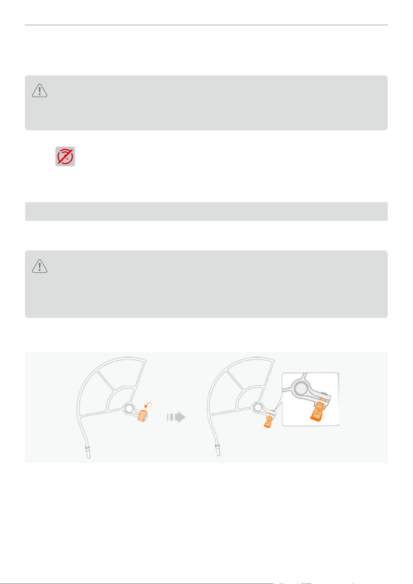
45
Antigravity A1 User Manual
©
2026 Antigravity All Rights Reserved
Enabling Obstacle Avoidance
The obstacle avoidance function is enabled by default and it can be manually disable in the Safety settings at the
bottom of the menu in the Vision Goggles.
� The obstacle avoidance function’s performance is affected by ight speed. Obstacle avoidance works
only in C mode or N mode but not in S mode, so exercise caution when ying in S mode.
� The drone will no longer detect obstacles when in manual ight or during executing ight routes, if you
disabled obstacle avoidance. You must navigate the drone to avoid obstacle manually.
When obstacle avoidance is turned off, the following icon will appear in the bottom right corner of the Vision Goggles
interface:
. Be caution when this icon is in red or in blinking pattern.
Obstacle Avoidance Action
The default obstacle avoidance action for the drone is to brake and hover when obstacles are detected.
Propeller Guards
Installing a propeller guard protects your drone from damages and signicantly reduces the risk of accidents. Please
follow the instructions below to install the propeller guard.
� The installation of propeller guards increases the drone’s Maximum Takeoff Mass (MTOM). This change
will affect ight performance, battery life, and image stitching parameters. Users should exercise caution
when operating the drone.
� After installation,the users must recalibrate the stitching settings in the Antigravity app and ofcial video
editing tool to ensure optimal visual effects. Visit the ofcial website for details.
Installing the Propeller Guards
1. Unlock the latches on the propeller guards.
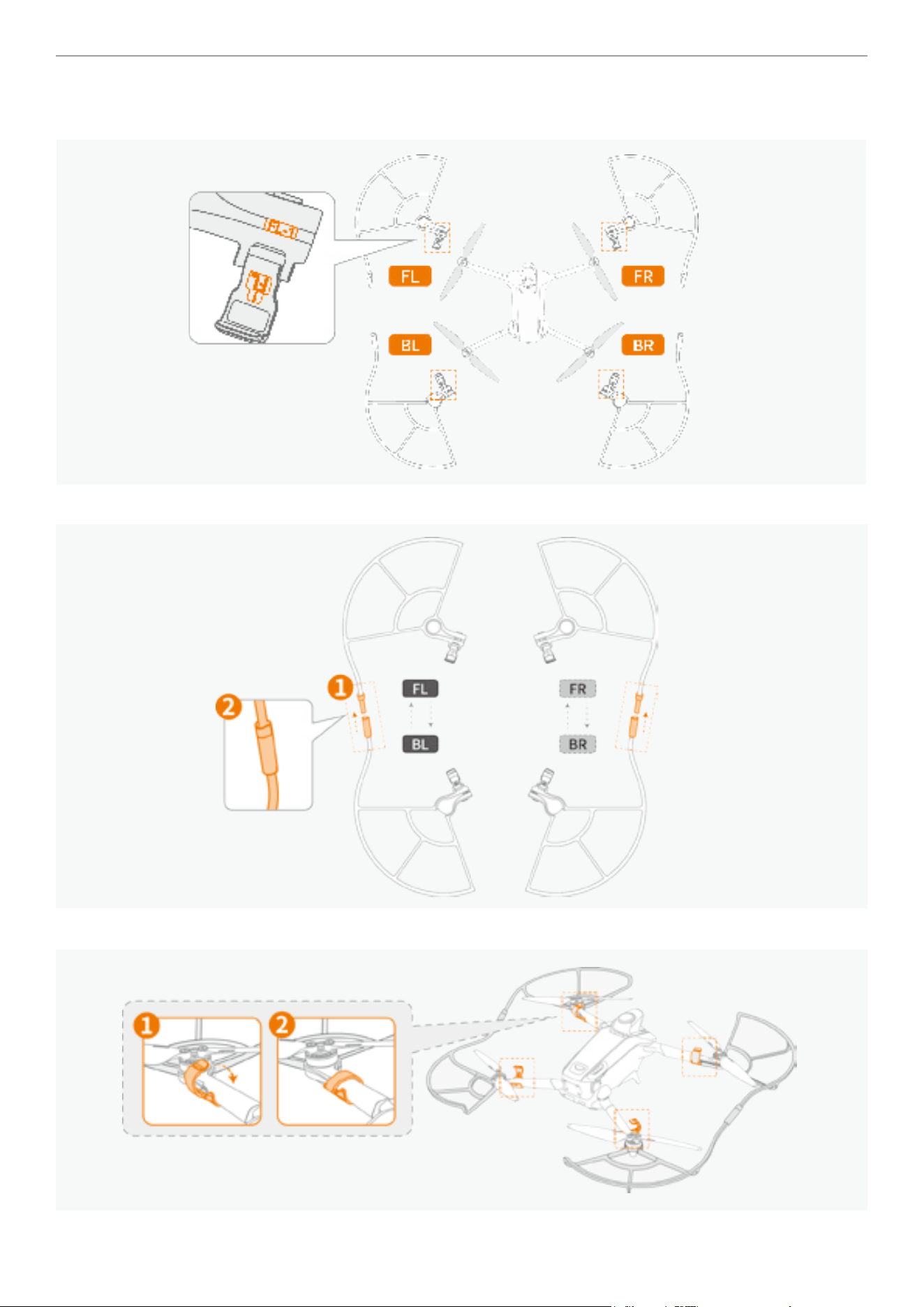
46
Antigravity A1 User Manual
©
2026 Antigravity All Rights Reserved
2. The propeller guards are distinguished by front (F), back (B), left (L), and right (R). Be sure to assemble the
components with the corresponding numbers together. The pairing of the components are displayed below:
3. Connect the front and back propeller guards using the markers located around the latches.
4. Attach the connected propeller guards onto the drone and lock the latches.
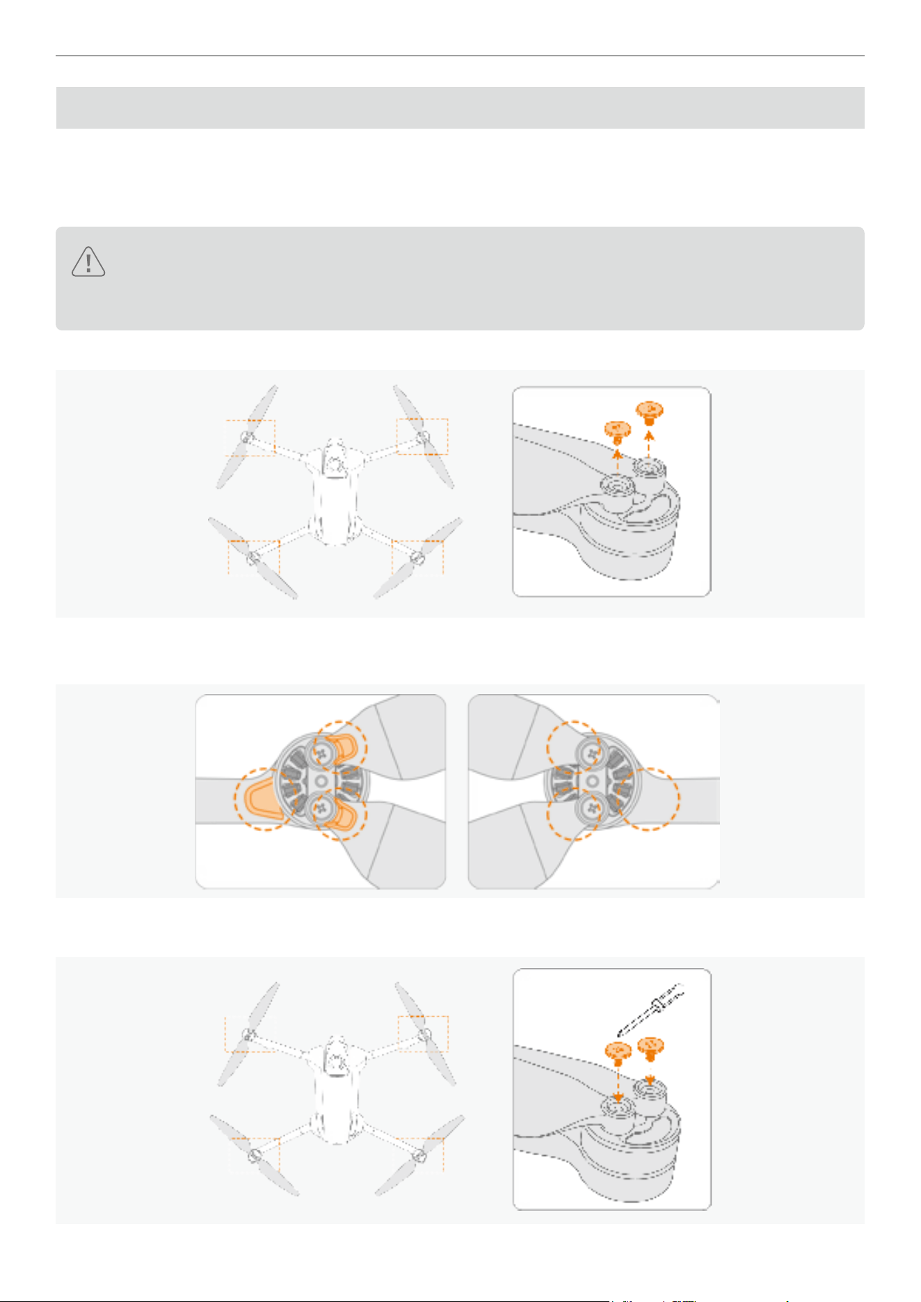
47
Antigravity A1 User Manual
©
2026 Antigravity All Rights Reserved
Propellers
Propellers are damage-prone and must be inspected for any damage after each ight. Users should regularly check
and replace them as necessary. The following section will describe how to replace propellers on drones.
How to Replace Propellers
� Discard the propellers set and the screws from the corresponding motor, do not reuse. When replacing
the new propellers set, use the propellers from the identical package.
� DO NOT mix with the propellers from other packages.
1. Remove the screws (M 1.2 × 2) from the motor by using the supplied screwdriver from the bundle.
2. Discard the legacy screws and propellers. Do not reuse.
3. Identify the markers on the propellers that match the appropriate motors. Refer to the gure below.
4. Mount the marked propellers onto the motors with the marker, and the unmarked propellers onto the unmarked
motors. Apply the specied torque when tightening the screws.
1.0 kgf cm

48
Antigravity A1 User Manual
©
2026 Antigravity All Rights Reserved
Flight Battery
Safety Notice for Flight Battery
� Do not expose batteries to moisture, as this may lead to combustion or explosion. If the battery comes
into contact with liquid, immediately remove it from the aircraft, place it in a safe, open area, and contact
technical support for assistance.
� Use of unsupported batteries is strictly prohibited. Always use the included charger for the best results.
� Do not use batteries that are swollen, leaking, or have damaged packaging.
� Avoid using batteries in high-temperature environments, as this may lead to battery ignition or explosion.
In low-temperature environments, performance may be affected, and caution is advised.
� Do not pierce the battery packaging.
� The battery electrolyte is highly corrosive. In case of leakage, avoid direct contact. If skin comes into
contact with leaked uid, immediately rinse with plenty of water and seek medical attention.
� Ensure batteries are stored out of reach of children. If a child accidentally swallows any part, seek
medical attention immediately.
� Do not reuse batteries that have fallen from a height, been exposed to water, or sustained visible
damage.
� In the event of a battery re, extinguish it in the following order:
a. If the battery is charging, disconnect it from the charger.
b. Cover the battery with sand or a re blanket.
c. Move ammable items away from a battery that is on re.
d. Extinguish the ames with a re extinguisher, then call emergency responders.
e. Use re-resistant tongs to place the battery into a non-ammable container lled with water to prevent
re-ignition.
� After the aircraft lands, allow the battery to cool down before charging to prevent issues.
� Do not place batteries near heat sources, such as inside vehicles on hot days, in direct sunlight, or near
open ames.
� Charge the battery to at least 60% before long-term storage. Charge it to 60% every three months during
storage to prevent over-discharge.
� Do not place batteries in re or hot stoves, and do not subject them to mechanical squeezing or cutting.
� Do not expose the battery to extreme heat environments as it may cause the battery to explode or leak
ammable liquids and gases
� Do not expose the battery to extreme low air pressure environments as it may cause the battery to
explode or leak ammable liquids and gases.
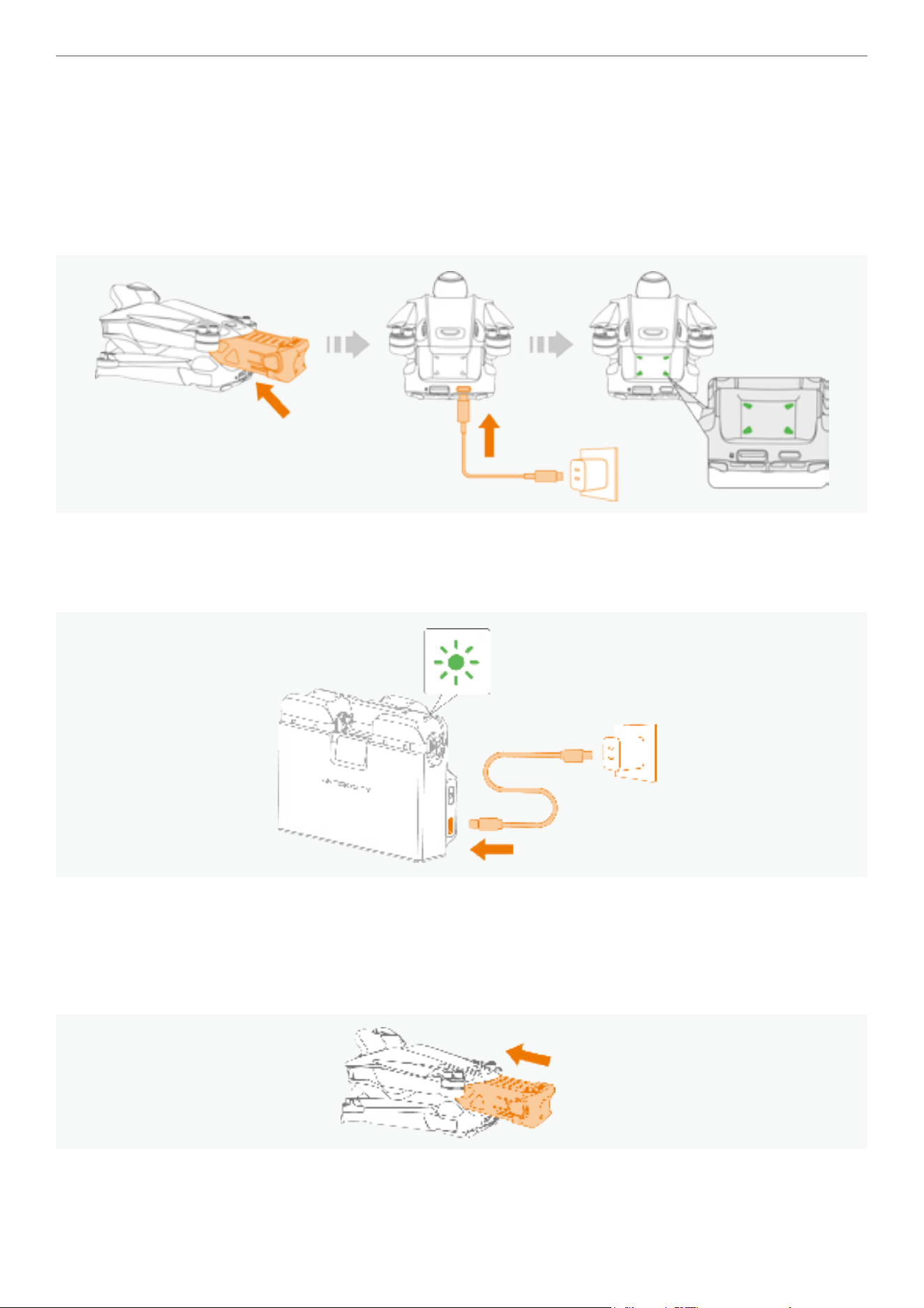
49
Antigravity A1 User Manual
©
2026 Antigravity All Rights Reserved
Activation of the Flight Battery
The battery is in sleep mode upon the delivery. You must activate it before the rst use. Follow one of the two
approaches to activate the battery.
Using the Charger to Activate
Insert the battery into the battery compartment of the drone, then connect the drone to the power source. The LED
indicators of the battery will ash green upon successful activation.
Using the Antigravity A1 Charging Hub to Activate
Connect the charging hub to the power source, insert the battery into one of the slots. The LED indicators of the
battery will ash green upon successful activation.
Using the Flight Battery
Installing and Removing the Battery
Insert the ight battery into the battery compartment of the drone. Make sure the battery is fully inserted and hear a
click, indicating that the battery latch is securely fastened.
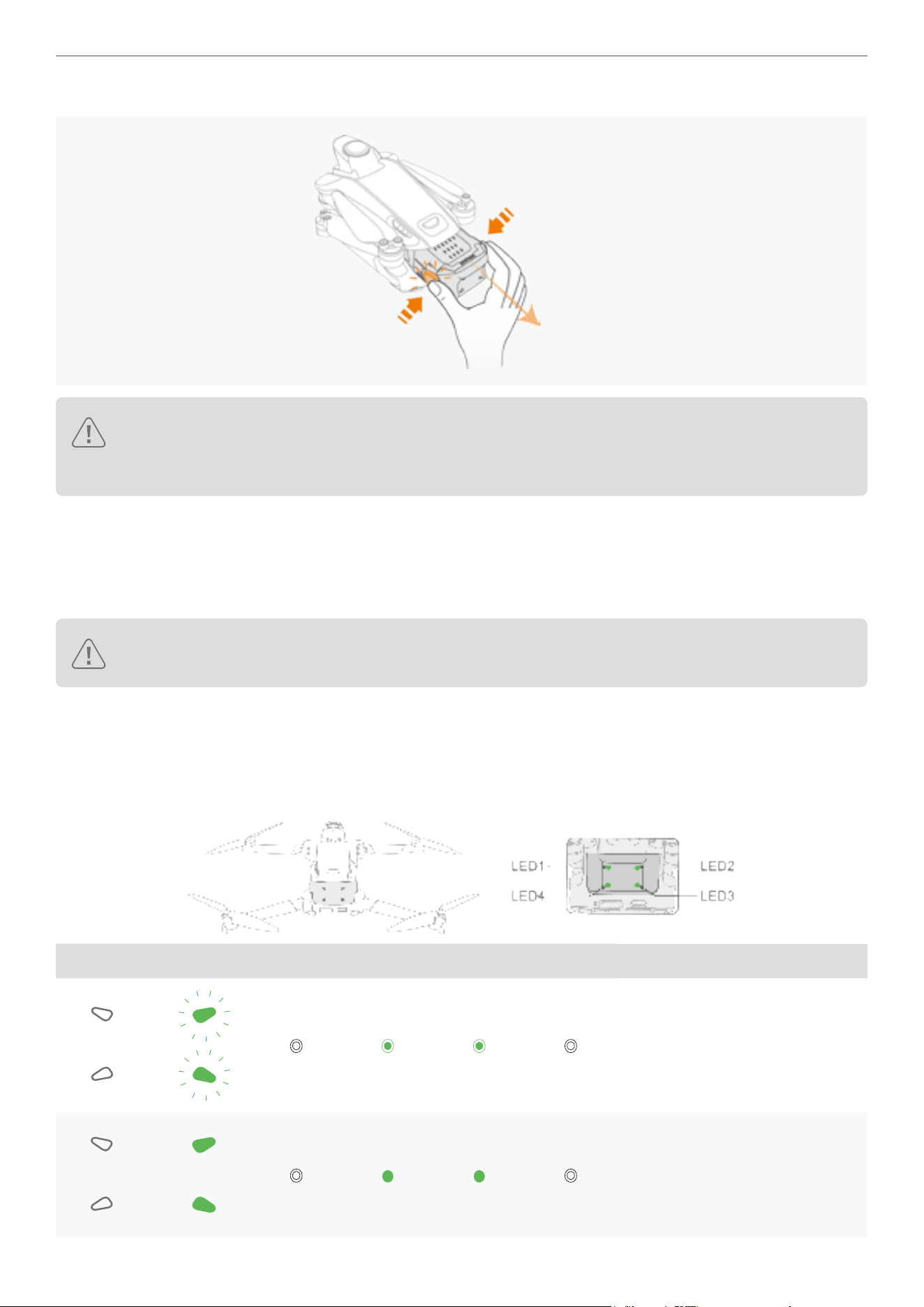
50
Antigravity A1 User Manual
©
2026 Antigravity All Rights Reserved
Press the battery latch on both sides of the battery, and remove the battery from the battery compartment.
� Do not insert or remove the battery while the drone is powered on.
� Ensure you hear a click when inserting the battery. Do not remove the ight battery if not securely
installed to avoid poor contact with the drone and potential danger.
Power On and Off
Press the power button on the drone once, then hold for two seconds to turn the drone on or off. When the drone is on,
the battery level LED on the ight battery touch area will indicate the battery level. When the drone is off, the battery
LED lights will turn off.
Data integrity of the ight recorder may be compromised if you do not follow the instructions to power off
the drone.
Flight Battery Firmware
Insert the battery into the drone, power on all three devices and launch the Antigravity App. Follow the in-app
instructions to update the rmware if new rmware is available.
The table shows the LED blinking pattern during the rmware update.
LED Blinking Pattern LED1 LED2 LED3 LED4 Firmware Update Status
Downloading new rmware.
Firmware update failed.
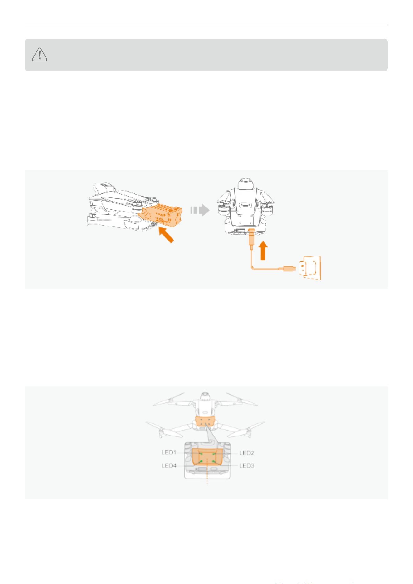
51
Antigravity A1 User Manual
©
2026 Antigravity All Rights Reserved
If the rmware update fails, insert the ight battery into the drone again and power it on. Retry the rmware
update from the Antigravity App.
Charging the Flight Battery
Use the supplied charger or the Antigravity A1 Charging Hub to charge the battery. Follow these steps below to
complete charging.
Using Charger
1. Ensure the battery is rmly inserted into the drone.
2. Connect the charger with appropriate adapter plug.
3. Attach the charger to the charging port of the drone.
4. The LED indicator blinks in sequence when charging. Press once on the power button of the drone to check the
current battery level.
5. The LED indicator turns off after charging completes.
Using Antigravity A1 Charging Hub
For instructions on how to charge with the A1 Charing Hub. Refer to “Battery Charging Hub” on page 52.
Battery Level Indicator
Tap once on the touch panel to check the battery level.
Touch area
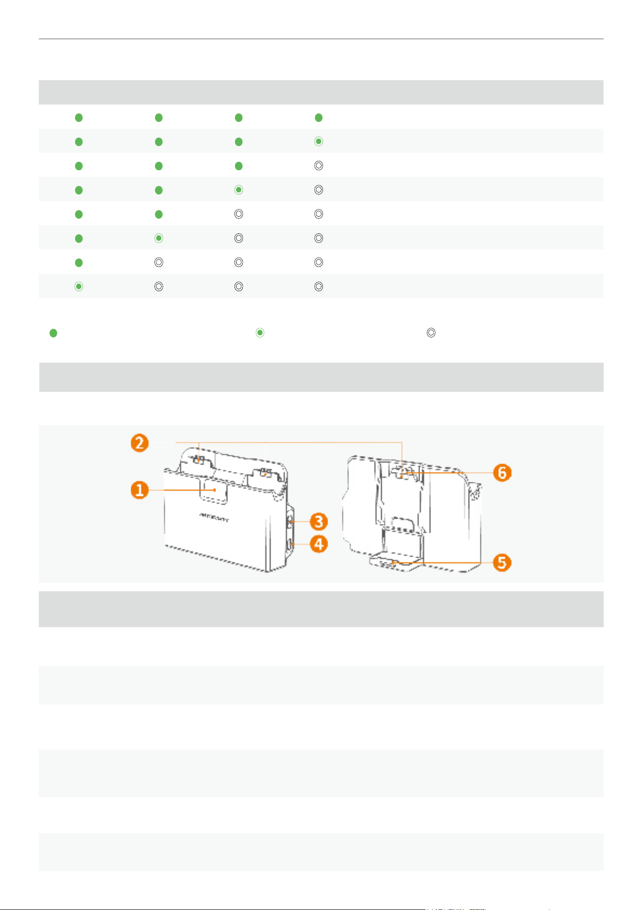
52
Antigravity A1 User Manual
©
2026 Antigravity All Rights Reserved
The blinking pattern of the battery LED indicators and corresponding battery levels are listed below:
LED1 LED2 LED3 LED4 Battery Level
88% - 100%
76% - 87%
63% - 75%
51% - 62%
38% - 50%
26% - 37%
13% - 25%
0% - 12%
LED Legends Denitions:
LED indicators display solid green LED indicators ash green LED indicators is off
Battery Charging Hub
Battery Charging Hub Overview
Item Description Function
1 Status Display Display of battery level and system status of the Battery Charging Hub.
2 Battery Slot Compatible with Standard and High-Capacity Flight Batteries.
3 Function Button
Press once to check battery level; Press and hold to activate Smart Power
Pooling mode.
4 USB Type-C Port
It is recommended to use the Antigravity 65W GaN fast charger, or another fast
charger that supports USB PD or PPS protocols, to ensure optimal performance.
5 Battery Bracket Flipped up when not in use.
6 Protection Cap Attached during the transportation. Store in a safe place for future access.
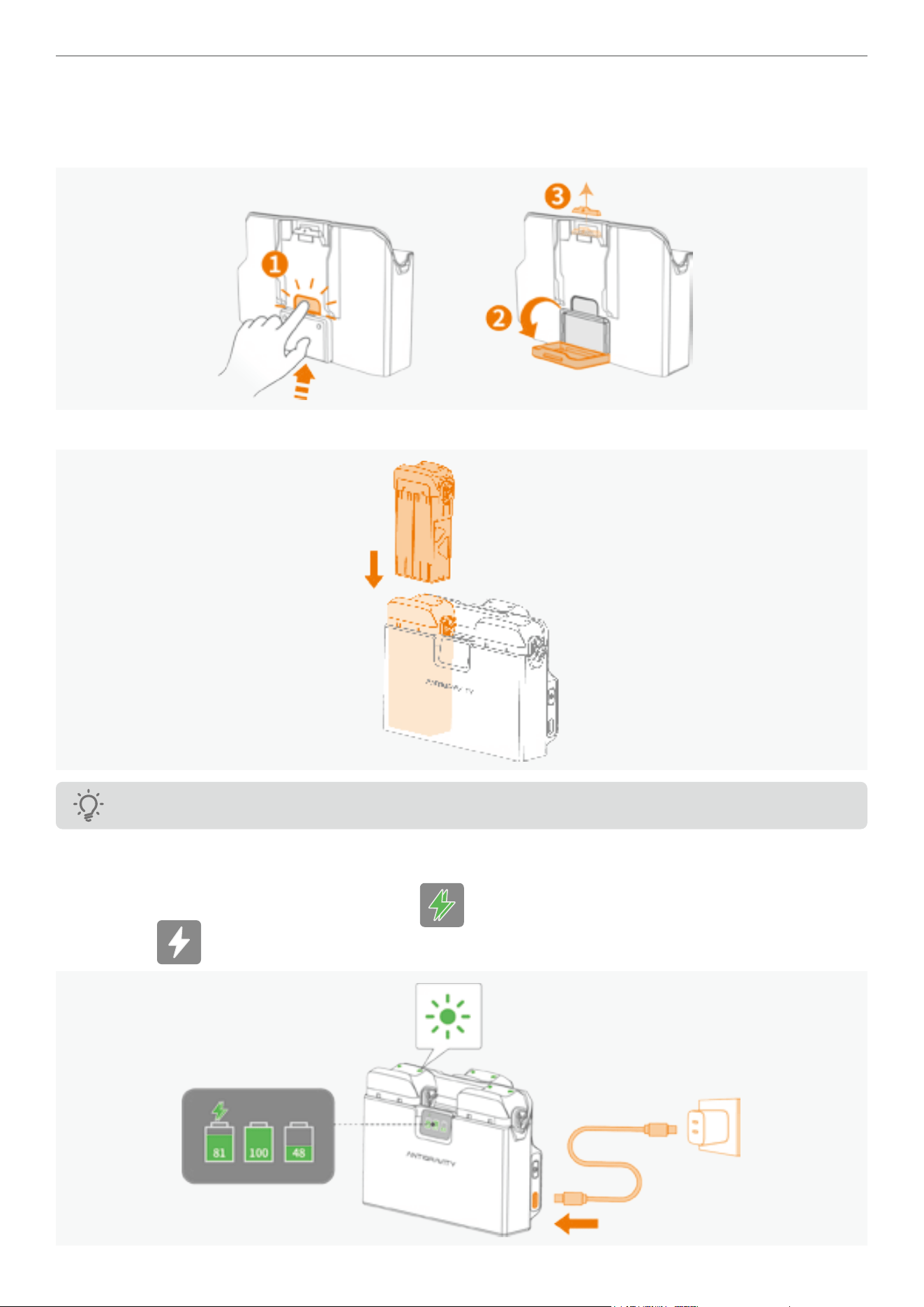
53
Antigravity A1 User Manual
©
2026 Antigravity All Rights Reserved
Regular Charging
1. Press the button to fold down the battery bracket. This allows for charging three batteries at the same time. Remove
the protection cap and store it in a safe place.
2. Insert the ight battery into the designated slots of the Battery Charging Hub until it clicks into place.
Be aware of pinching when inserting the battery.
3. Connect the Charging Hub to an AC power source using the supplied USB Type-C cable. The hub charges the
batteries in sequence based on their remaining power, and the status display panel indicates their charge levels
during charging. During charging, the green icon ( ) indicating that the hub is in fast charging mode, while the
white icon ( ) indicating that the hub is in slow charging mode.
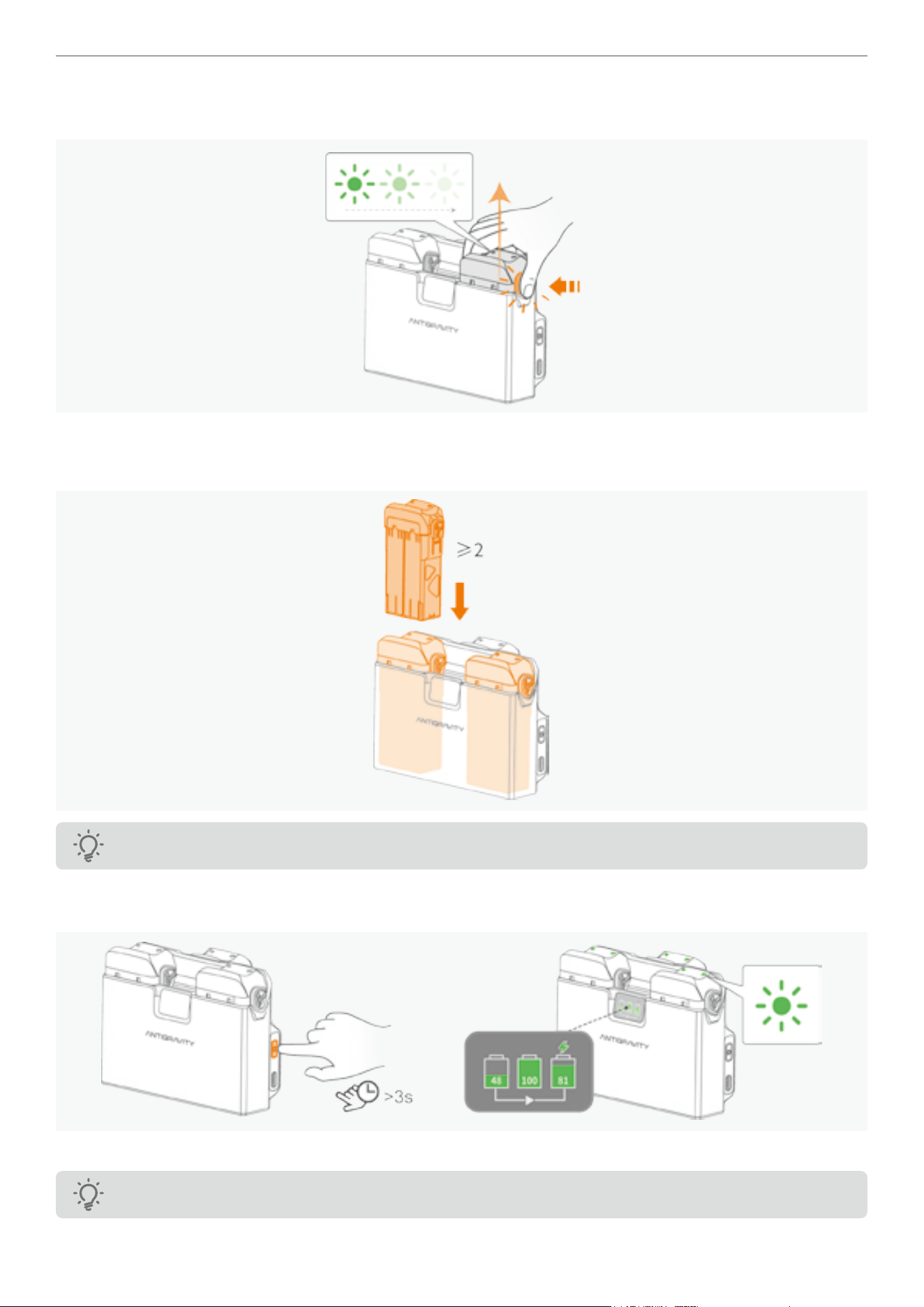
54
Antigravity A1 User Manual
©
2026 Antigravity All Rights Reserved
4. When charging is complete, the status LED on the drone battery stops blinking and turns off. Pinch and hold the
clips on the top of the battery to remove it.
Smart Power Pooling
1. Insert two or more ight batteries into each slot of the Battery Charging Hub until it clicks into place.
Be aware of pinching when inserting the battery.
2. Press and hold the Function Button on the Charging Hub to activate Smart Power Pooling. Once enabled, the status
panel displays low-power batteries transferring charge to the highest-capacity battery.
3. To stop the Smart Power Pooling, press and hold the Function button during the process.
The battery level must be higher than 20% to activate the Smart Power Pooling.
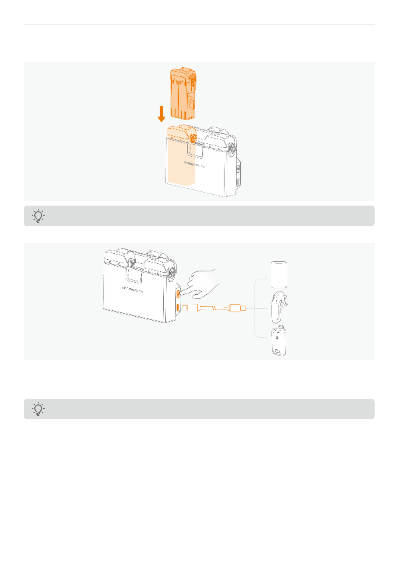
55
Antigravity A1 User Manual
©
2026 Antigravity All Rights Reserved
Power Bank
1. Insert at least one ight battery into the Battery Charging Hub.
≥1
Be aware of pinching when inserting the battery.
2. Connect an external device (such as a mobile phone or motion controller) to the USB Type-C port on the hub.
3. Press the Function Button once to begin charging the external device using the power from the inserted battery or
batteries.
4. To stop charging, disconnect the external device from the hub.
The battery level must be higher than 10% to activate the power bank mode.
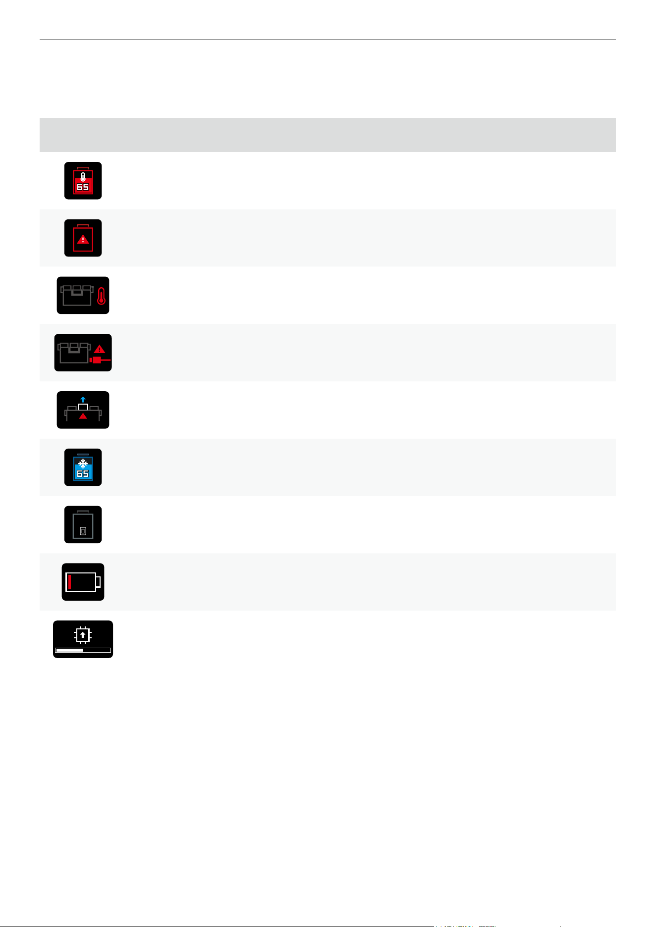
56
Antigravity A1 User Manual
©
2026 Antigravity All Rights Reserved
Battery Charging Troubleshooting
The Status Display on the charging hub can display the current system status and provide various error messages.
Refer to the table below to nd out the meanings of the each icons.
Icon Description How to resolve
Overheat warning Power off and allow cooling.
Battery error
Unplug and insert the battery back into the hub. If the problem
persists, contact the customer service for assistance.
Battery Charging Hub overheat Disconnect the power source to cool down.
Critical error
Unplug and insert the USB Type-C power source back to the
port, if the problem persists, contact the customer service for
assistance.
Battery Charging Hub system
error
Remove and insert the battery and reboot the Charging Hub.
If the problem persists, contact the customer service for
assistance.
Battery temperature low Let the battery sit at room temperature.
Unactivated battery or low
battery level
Connect the hub to the power source to activate or charge the
battery.
Low battery level Connect the hub to the power source to charge the battery.
Firmware update in progress Await update process completes.

57
Antigravity A1 User Manual
©
2026 Antigravity All Rights Reserved
Transferring Footages
To transfer extensive footage for editing, it is recommend using the Antigravity Quick Reader to export data from the
drone to your editing device.
Quick Reader
The Quick Reader provides both a USB Type-C and a Lightning connector. Remove the cap of your desired connector
in order to gain access to the connector.
1. Extract the SD card from your device after powering it off.
2. Locate the SD card slot on the side of the Quick Reader.
3. Connect the Quick Reader to the mobile device.
4. Launch the Antigravity App and follow the onscreen instructions to transfer the les.
5. You can now download, export, delete, and perform other simple operations in the Antigravity app.
� Do not modify the le name of the footage during footage transmission to the Quick Reader.
� The Quick Reader does not support exporting data from the Vision Goggles.
58
Antigravity A1 User Manual
©
2026 Antigravity All Rights Reserved
Quick Transfer from Antigravity App
Apart from using the Quick Reader, users can also quickly transfer the footages captured by the drone to their mobile
device through wireless connection via the app. Please follow the steps below to export the footages:
When transferring the footages, users will not be able to take off the drone.
1. Power on the drone. Turn on the Bluetooth and WiFi switches on your mobile device.
2. Launch the Antigravity app and select to connect to the drone.
3. In the album page of the app, choose Quick Transfer - Connect devices - Connect.
4. Once connected successfully, the App will display the list of materials in the drone. Select the footages and proceed
with the download.
Vision and Infrared Sensing System
Features
The drone is equipped with downward and forward vision systems as well as infrared sensing systems, these systems
work together to safeguard the ight of the drone. The main feature of the vision perception system include:
1. Vision Positioning:
Construct a three-dimensional model using cameras, infrared TOF, and AI algorithms to support autonomous
obstacle avoidance, dynamic target tracking, and precise landing functions.
2. Obstacle Avoidance:
The forwards obstacle avoidance system can detect obstacles in front of the drone ranging, ensuring safety during
ight; the downward obstacle avoidance system is mainly used to detect obstacles beneath the drone, assisting the
drone in avoiding collisions with the ground or other objects during takeoff, landing, and low-altitude ight.
The drone cannot detect obstacles while it is ascending. User discretion is required to navigate obstacles
directly above the drone.
Vision and Infrared System Safety Notices
� Environmental Factors:
· Vision and infrared sensing systems operate only in specic scenarios and cannot replace manual
control and judgment. In low-light conditions, even with supplementary lighting, the vision system may
not perform optimally.
· The downward vision system may not work properly when ying close to the water surface (around 3
meters), user’s desecration is advised.
� The vision system may struggle to identify large structures with frames and cables. Stay away from
these structures.
� The system may not function properly near surfaces with no distinct pattern changes, areas with weak
or strong lighting, extremely dark or bright surfaces, or surfaces that reect or absorb infrared waves.
� Flight Altitude:
· The downward vision system works best at altitudes ranging from 0.3 to 7.5 meters when the GNSS
signal is weak. Performance may degrade when ying above 10 meters.
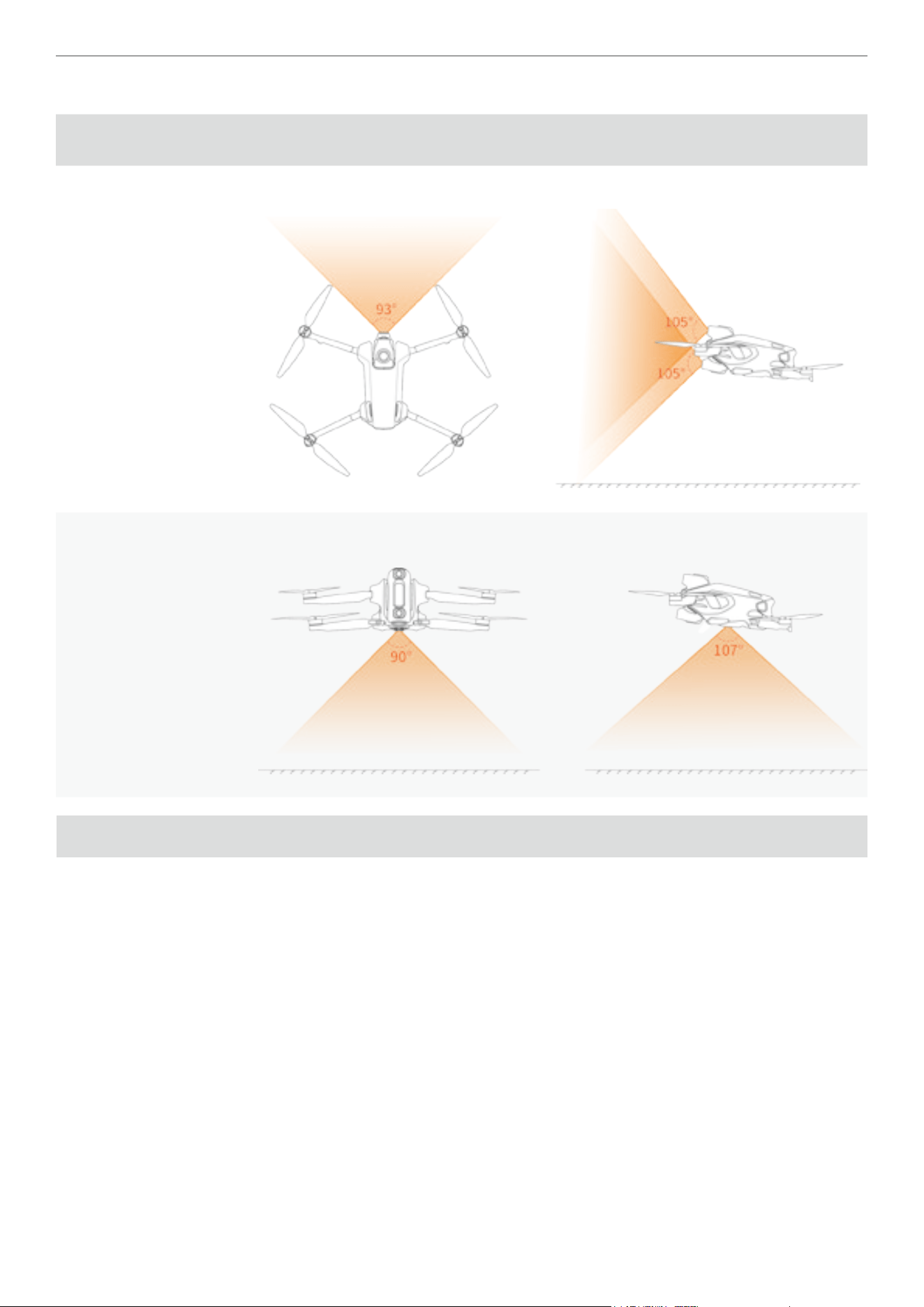
59
Antigravity A1 User Manual
©
2026 Antigravity All Rights Reserved
Vision Position Detection Range
Sensor
Direction
Range Field of View (FOV)
Forward 0.5 m to 18 m
Horizontal 93°, Vertical 105°
Downward 0.3 m to 10 m
Horizontal 107°, Vertical 90°
Flight Recorder
After each takeoff and landing, the drone's ight telemetry data, ight status information, and other parameters will be
automatically saved to the built-in storage card. Users can access this data through the application (Antigravity app).
Vision Goggles
Vision goggles is an intuitively designed device for interaction, equipped with a variety of functions to provide users
with a comprehensive ying experience.
� Video Transmission: Equipped with high-resolution and wide color gamut dual OLED screens, supporting wireless
connections such as WiFi, Bluetooth 5.3, etc.
� Screen Recording : Screen recording settings include recording of the vision goggles screen (option to record
OSD information or only the image transmission screen) and voice recording.
� Instant playback: Supports playback of various video formats, allowing you to view captured materials without
exporting them.
� Customize feature: Provides custom video display function, showcasing individuality.
� Safety: Provides voice prompts in case of emergency situations during the ight.
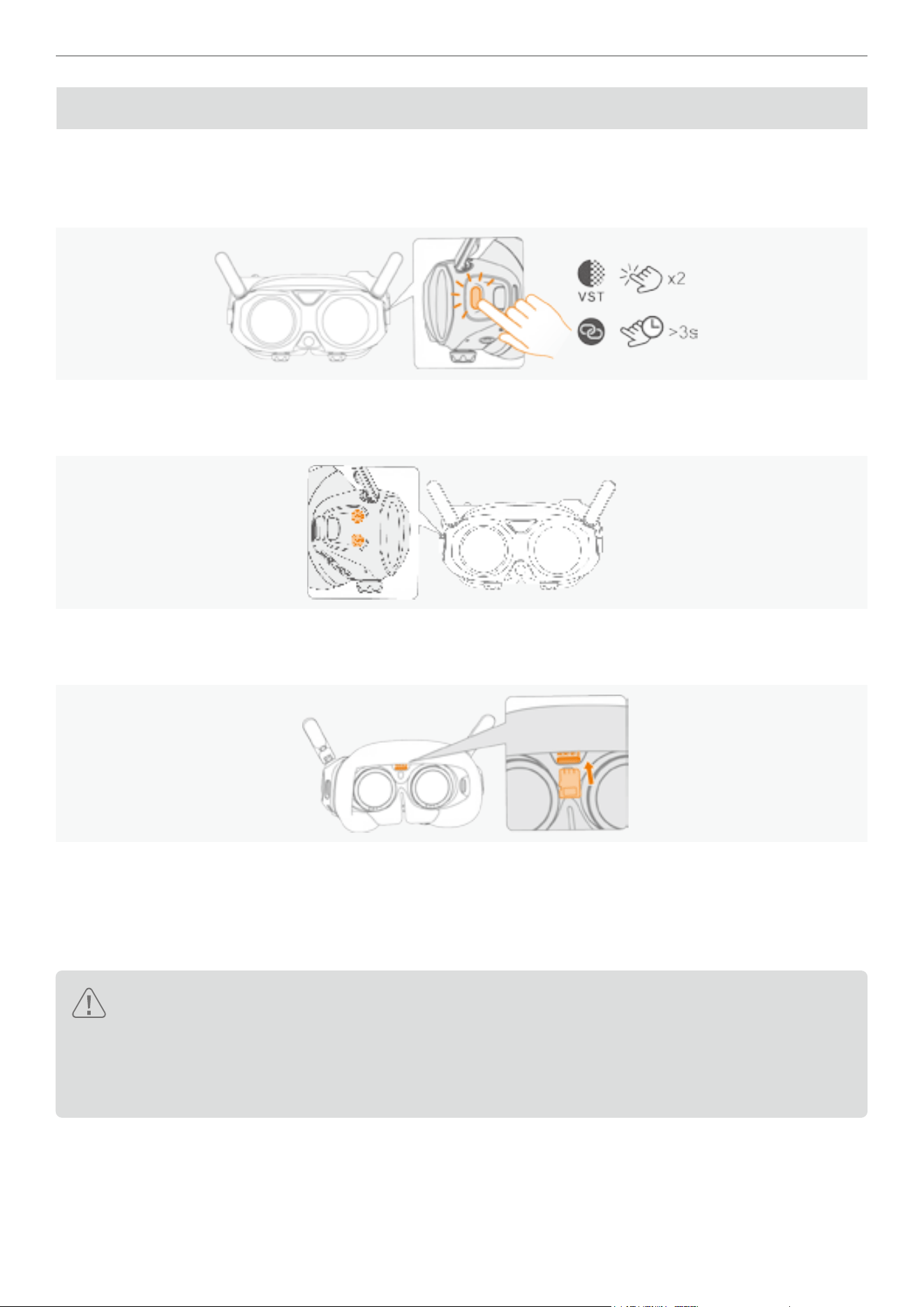
60
Antigravity A1 User Manual
©
2026 Antigravity All Rights Reserved
Vision Goggles Overview
Home Button
Press the Home button twice to enable the feature “Video See-Through” on page 71. Press and hold the Home
button to enter linking mode.
Volume Buttons
Use the up and down arrow keys to adjust the volume of the voice prompts or video play from the speakers.
MicroSD Card Slot
The MicroSD slot situated between the two lenses, refer to the gure below.
Insert the SD card gently as shown in the gure. To remove the SD card, press inward with a ngernail or a thin
pointed object until you hear a click, then the SD card will pop out.
Power Port
The location of the power port for the Vision Goggles is shown in the following gure.
� The Vision Goggles do not come with a built-in battery and must be powered by an external power source.
� The Vision Goggles must be powered by the supplied Antigravity Vision Goggles USB-C to DC power
cable. It is not compatible with an external USB cable.
� Keep the power port dry at all times; otherwise, the Vision Goggles will not function properly. In case of
water damage or moisture, use a hair dryer to dry the affected port.
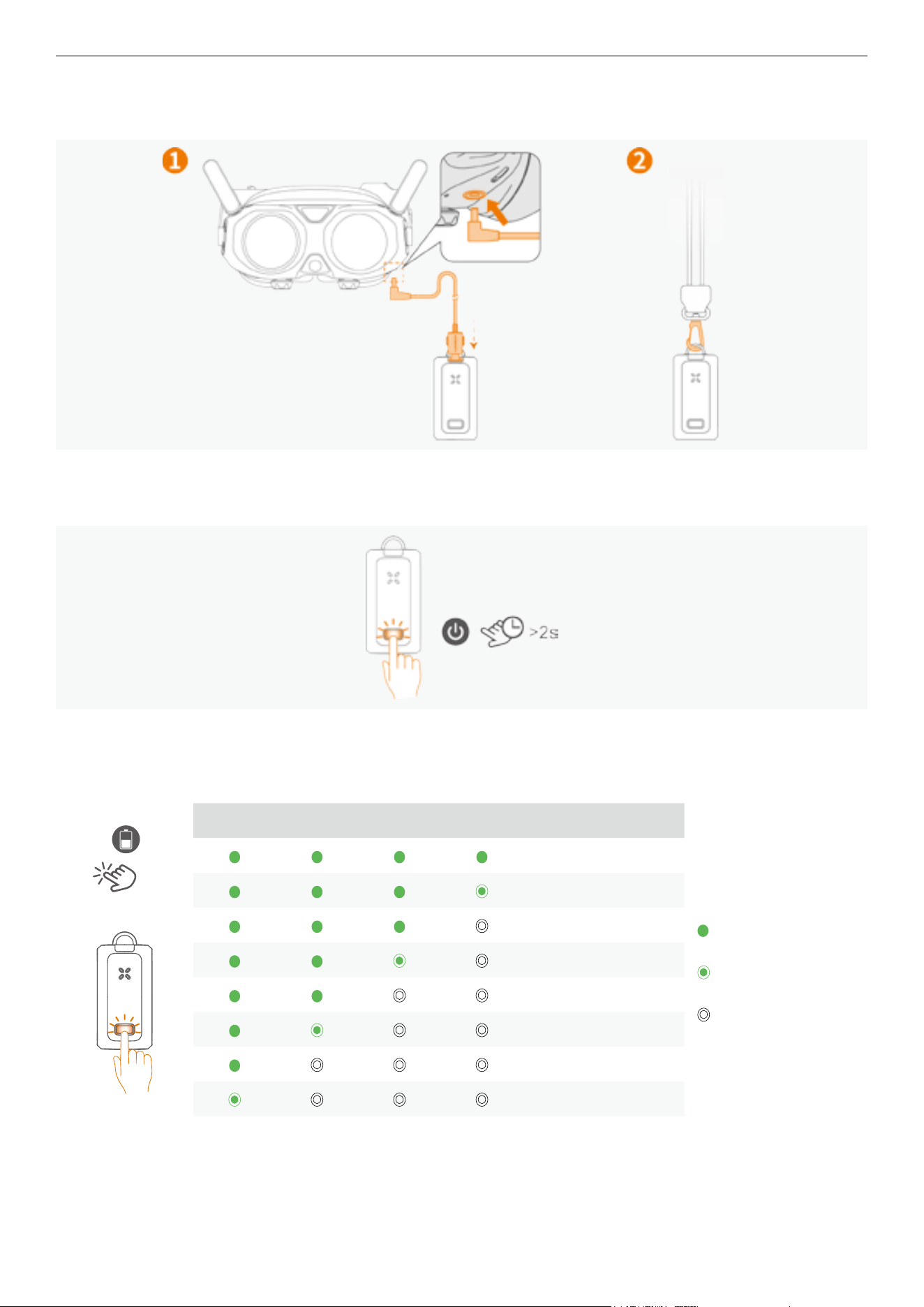
61
Antigravity A1 User Manual
©
2026 Antigravity All Rights Reserved
Use the Vision Goggles USB-C to DC charging cable to connect the Vision Goggles battery to the Vision Goggles, and
attach the Vision Goggles battery strap to the buckle.
Power on the Vision Goggles
Press and hold the power button on the Vision Goggles battery for more than two seconds to power on.
Battery Level on the Vision Goggles Battery
Short press the power button once to check the current battery level of the Vision Goggles. For detailed information
about the battery level, refer to the table below.
x1
LED1 LED2 LED3 LED4 Battery Level
Legends Denitions:
LED indicators display
solid green
LED indicators ash
green
LED indicators is off
88% - 100%
76% - 87%
63% - 75%
51% - 62%
38% - 50%
26% - 37%
13% - 25%
0% - 12%
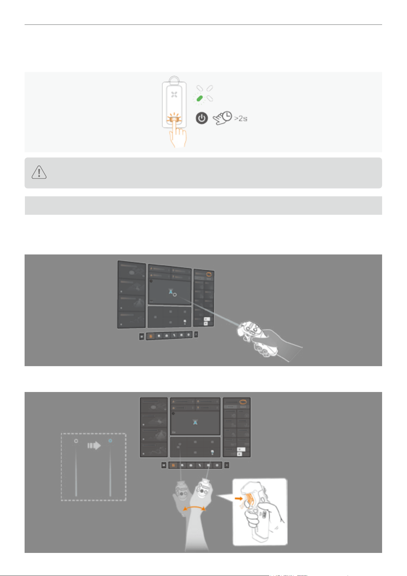
62
Antigravity A1 User Manual
©
2026 Antigravity All Rights Reserved
Powering Off the Vision Goggles Battery
Press and hold the power button on the Vision Goggles battery for more than two seconds to power off. During the
process, the LED4 will blink and turn off at the end.
�
To ensure the integrity of the data, please make sure to use the power switch to turn on or off the Vision Goggles.
� Do not power off the Vision Goggles by unplugging the power cord.
Virtual Beam
Basic Operations
While the drone is on the ground or hovering, you can interact with the Vision Goggles by using the Motion Controller
via the virtual beam. It is represented as a straight white ray with a circular circle at the end.
� Waving your arm to move the virtual beam within the Vision Goggles menu. Pressing the throttle trigger to conrm
the current selection and the white circle at the end of the beam will change to blue.
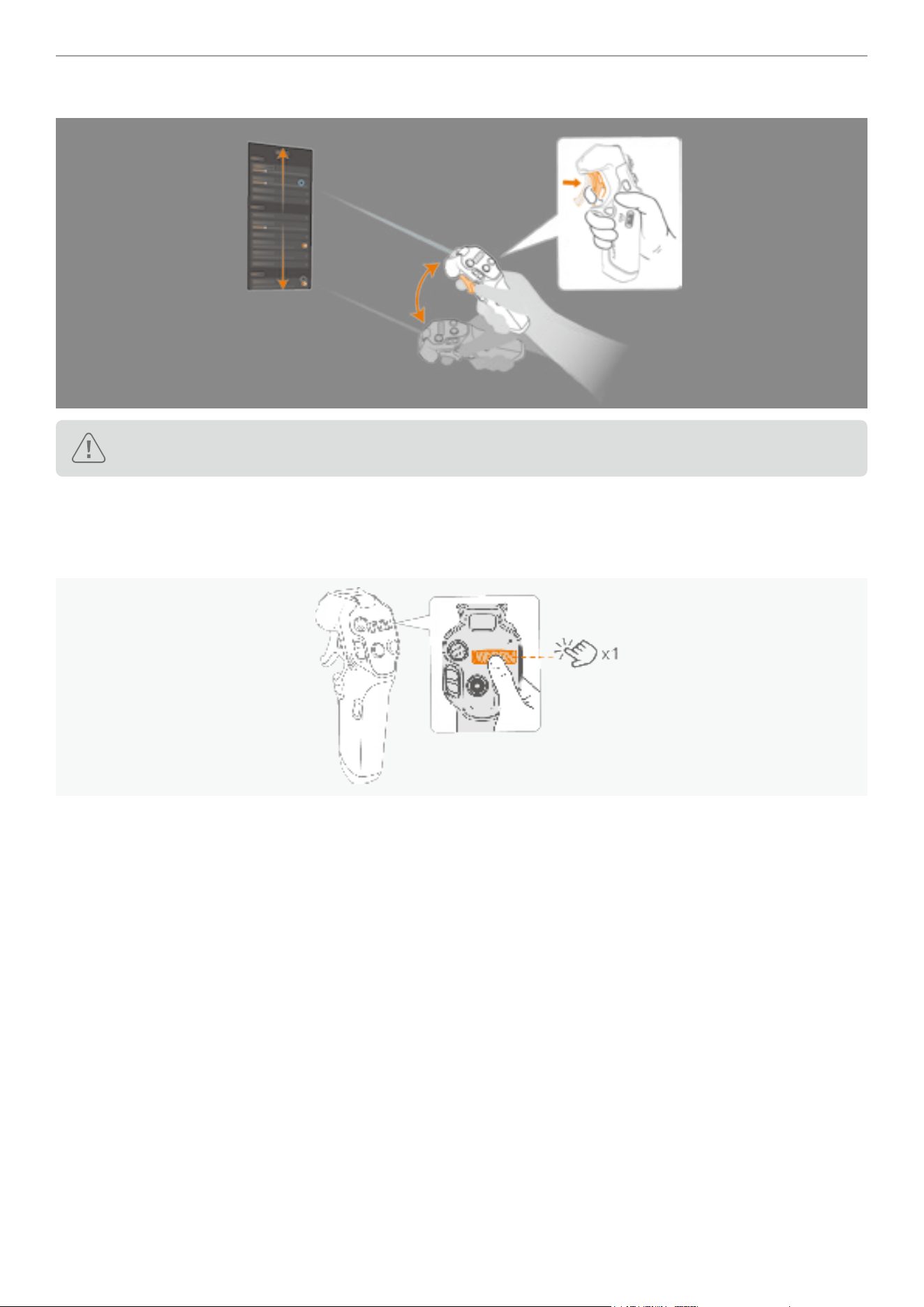
63
Antigravity A1 User Manual
©
2026 Antigravity All Rights Reserved
� While pressing the throttle trigger, swipe upward or downward to scroll through the menu options.
Be sure to remain still and use the virtual beam function in a safe environment on at ground.
Re-center the Menu
If the Vision Goggle menu UI component has shifted away from the central position, press the 360 dial once to return
the menu to the center position.
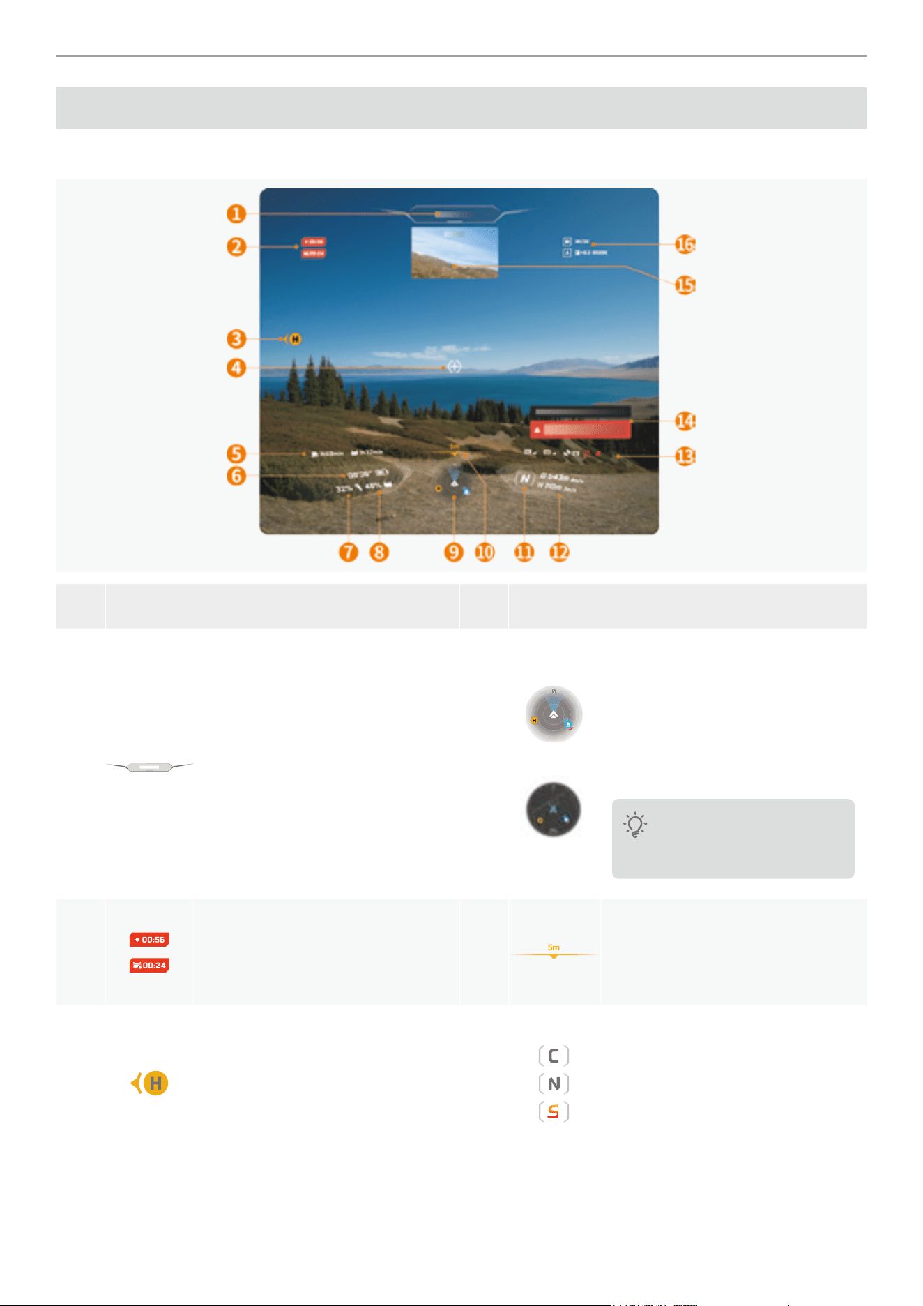
64
Antigravity A1 User Manual
©
2026 Antigravity All Rights Reserved
Vision Goggles Menus
Flight Menu
Item Description Item Description
1
Flight Status Bar
Provides real-time information on
drone ight status, including take-
off/landing and GNSS signal status.
The bar is green when the drone
is in normal state, and turns yellow
or red when user's discretion is
required.
9
Radar / Mini Map
It shows drone's orientation relative to
horizon and heading, and position in
relation to return point H. When drone
enters return mode or uses preset
route, area switches to small map.
Map varies depending on
the country or region where
activation occurs.
2
Video/ Screen Recording Time
Displays the duration of video or
screen recording.
10
Downward Vision Sensing
Display the distance to the detected
obstacle.
3
Home Point
Orange H mark shows last recorded
Home point location, with arrow
indicating direction relative to
drone's heading.
11
Flight Mode
Shows current ight mode. For
more details, refer to “Flight Mode”
on page 35.
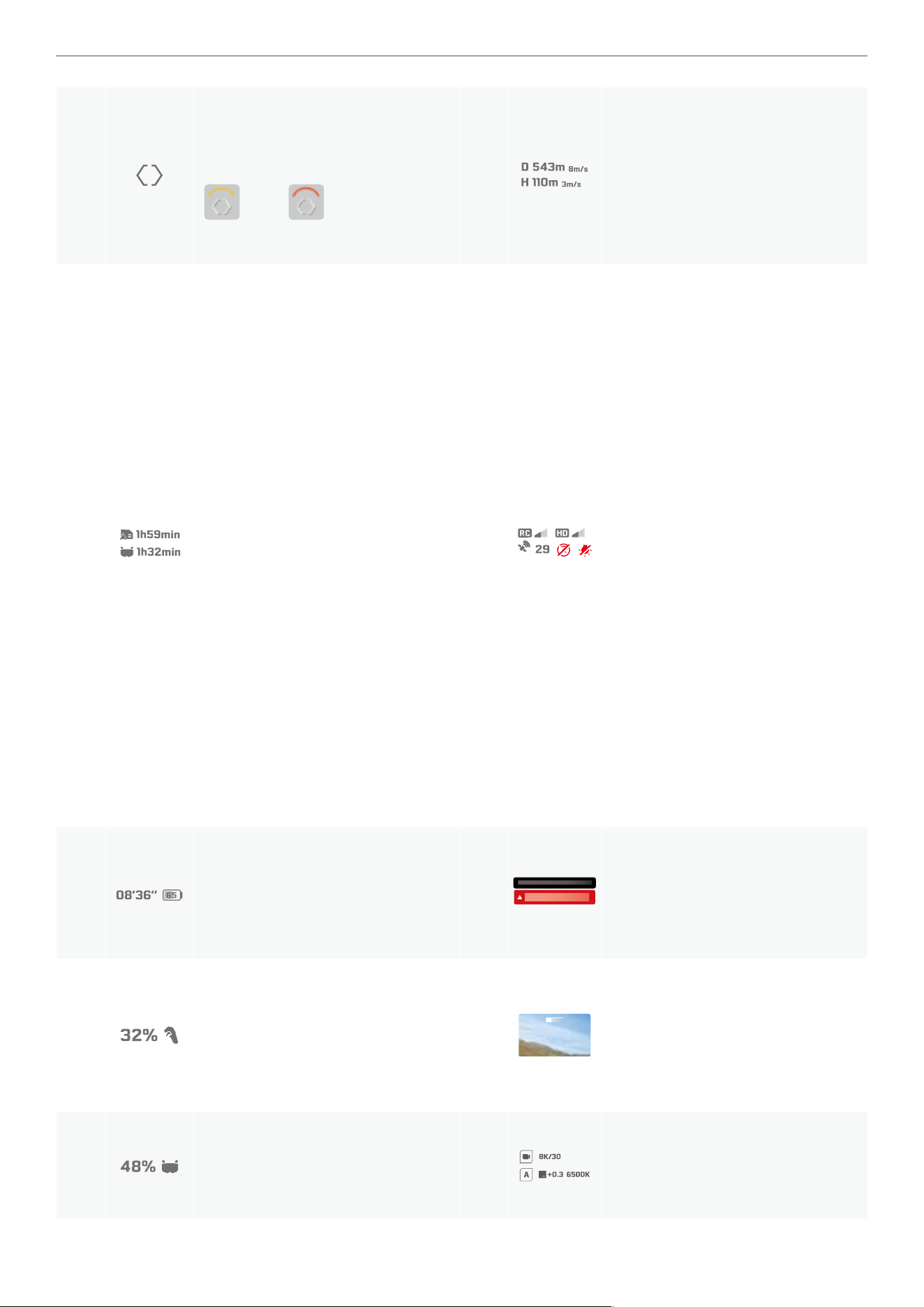
65
Antigravity A1 User Manual
©
2026 Antigravity All Rights Reserved
4
Navigation Point
Indicating where the drone is
heading toward. It will turn yellow
or red when obstacle is
detected on the ight path.
12
Flight Speed and Distance
�
D
denotes the distance between
the drone to the Home point with
vertical speed.
�
H
denotes ight altitude and the
vertical speed.
5
Footage Storage
Display the remaining time the
drone can shoot videos and the
remaining time the ight glasses
can record screen according to the
current settings.
13
RC and Video Signal / Obstacle
Avoidance
� Display the strength of the video
transmission signal of the Vision
goggles, the strength of the GNSS
signal, whether the obstacle
avoidance system is enabled,
whether the landing light is on or
off.
� Display the signal strength of
the remote control device and
the image transmission signal
strength between the drone and
the Vision Goggles.
� The icon is white when the video
transmission signal is strong, and
turns gray when the signal is lost.
� The icon is orange when the signal
strength is moderate, and turns red
when the signal is extremely weak.
The white icon indicate signal is
strong.
6
Drone Battery Level
Display the current battery level and
the estimated remaining ight time
duration.
14
Notication Area
Display system alert messages that
require user action, such as battery
low warning messages.
7
Motion Controller Battery Level
Displace current battery level for the
controller.
15
Picture-in-picture
Display heading of the Navigation
Point direction. It is enabled when
the Navigation Point is deviated
from the head tracking of the user.
8
Vision Goggles Battery Level
Displace current battery level for the
Vision Goggles.
16
Camera Parameters
Display the current camera prole.
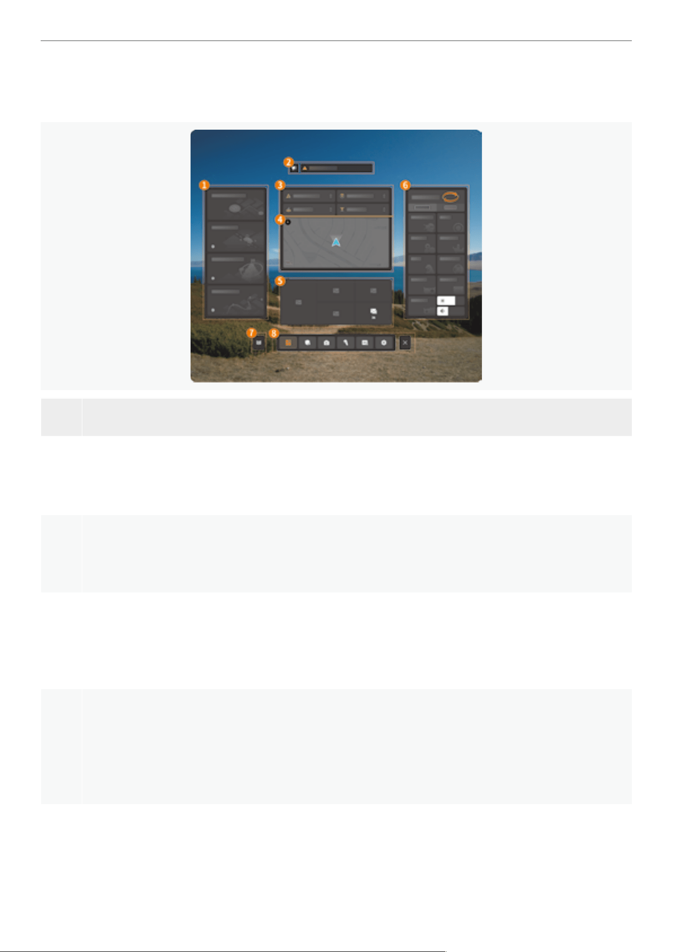
66
Antigravity A1 User Manual
©
2026 Antigravity All Rights Reserved
Vision Goggle Menu
When the drone is on the ground and powder on or is hovering in the air, users can access the Vision Goggles via the
pressing on the menu button on the Grip Motion Controller. The layout of the Vision Goggles menu is as follow:
Item Description
1
Advanced Flight Path
You can trigger automatic RTH or use the Deep Track feature to follow the subject that you wish to lm, or
pre-plan your shot using the Sky Genie and feature from this panel.
2
Notication Area
Display various ight control system status information and the latest user notices, including but not limited
to rmware update notications, ight protections zone database updates, and other information.
3
Flight Safety Menu
Users can quickly set and adjust ight safety-related parameters and behaviors through the virtual beam.
This includes behaviors in the case of signal loss, obstacle avoidance behaviors, RTH altitude, and maximum
altitude values.
4
Mini Map
After the Vision Goggles are connected to the mobile app, the mini-map will display geographic location
information of the current area. Users can use this interface to check if there are any restricted ying zones
near the ight area. When using features like preset routes, users can view route information through the
mini map.
5
Photo Album
Display photos or videos stored in the memory of the Vision Goggles or on the MicroSD card. Select any
le for preview. After connecting to the drone, you can preview or play photos or videos stored on the drone.
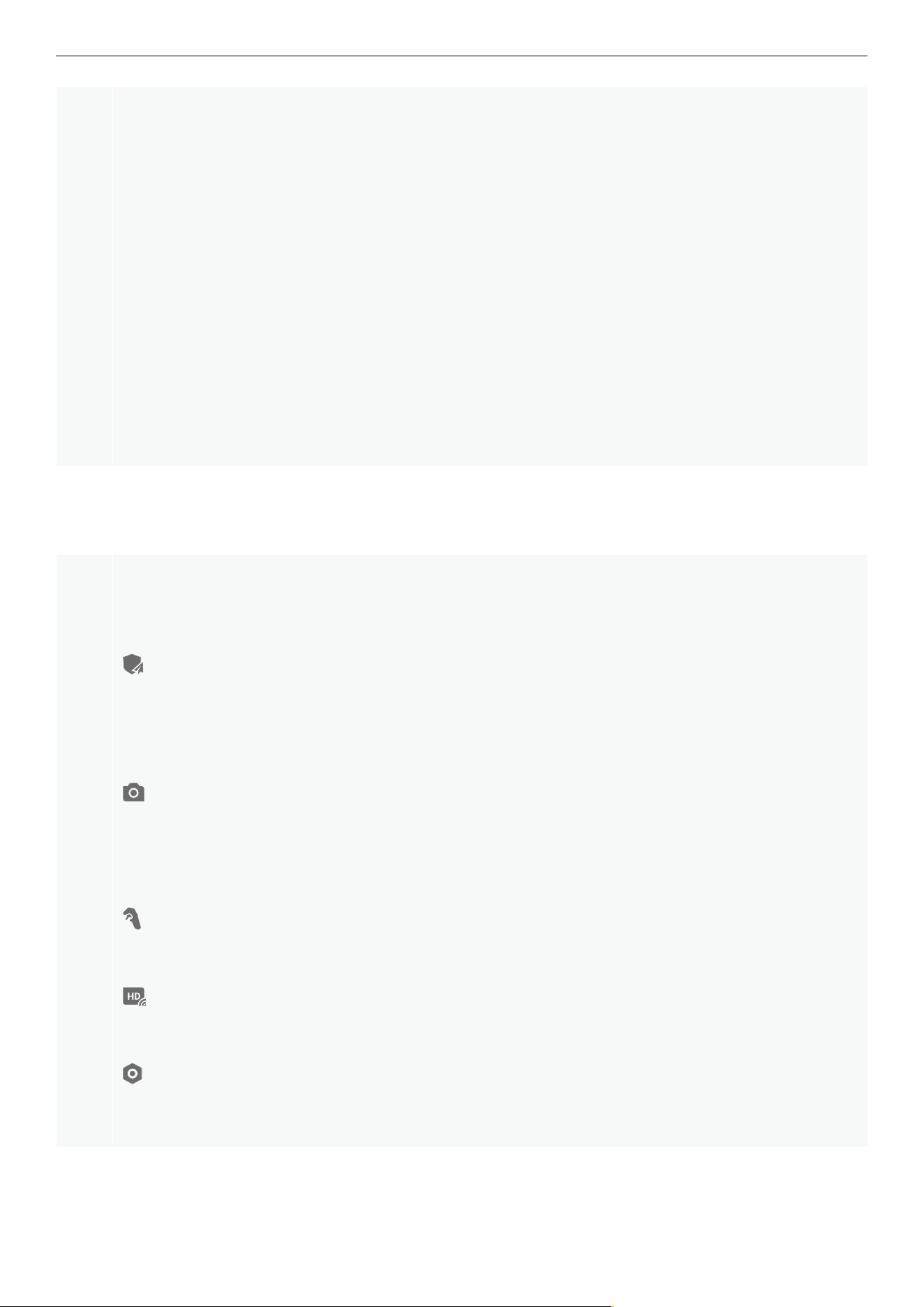
67
Antigravity A1 User Manual
©
2026 Antigravity All Rights Reserved
6
Control Mode and Quick Access
· Flight Control Mode: Toggle between Free Motion and FPV Mode.
· Screen Capture: Record the user's rst-person view and the pick up the surrounding sound and various
menu operations. You can choose to store the recordings in the memory of the Vision Goggles or on an
external storage card.
· De-fog: Activate the built-in fan to accelerate the evaporation of moisture.
· Video Transmission Setting: Set parameters such as image transmission aspect ratio.
· Brightness and Volume Adjustment: Adjust the image brightness of the ying goggles, adjust the
volume of language prompts, and playback video volume.
· Camera Parameter Settings: Adjust resolution, frame rate, EV and white balance in this section.
· Virtual Cockpit: In FPV mode, you can choose different virtual cockpit skin.
· Outer Display and Ring Light: Set the what to be display on outer display and select the visual effect.
· Customizable Buttons: Set the functions corresponding to the C1 and C2 buttons.
7
Video Tutorials and Documentations
View the ofcial videos tutorials and documents provided.
8
General Settings
When the Vision Goggles are connected to the drone, users can make the following settings through the
Setting page:
· Set up ight protection areas, return behavior, and RTH height information.
· Find drone information.
· Enable or disable automatic landing gear retraction function.
· Flight battery and rmware version.
· Advanced shooting settings, users can ne tune various settings such as framing guidelines, histograms,
low-light stabilization.
� Users can also reset camera settings on this page.
· After each replacement of the lens, calibration stitching operations need to be performed from this page.
�
Adjust advanced settings such as throttle control curve for the overall remote controller feel.
· Adjust the mapping relationship of the C1 and C2 custom button functions.
� Set the transmission mode of the image transmission, including options for image aspect ratio, and
transmission channel for the image transmission, etc.
· In general settings, users can set up account information, update rmware, check the device's rmware
version, update ight protections zone data, and perform other operations on this interface.
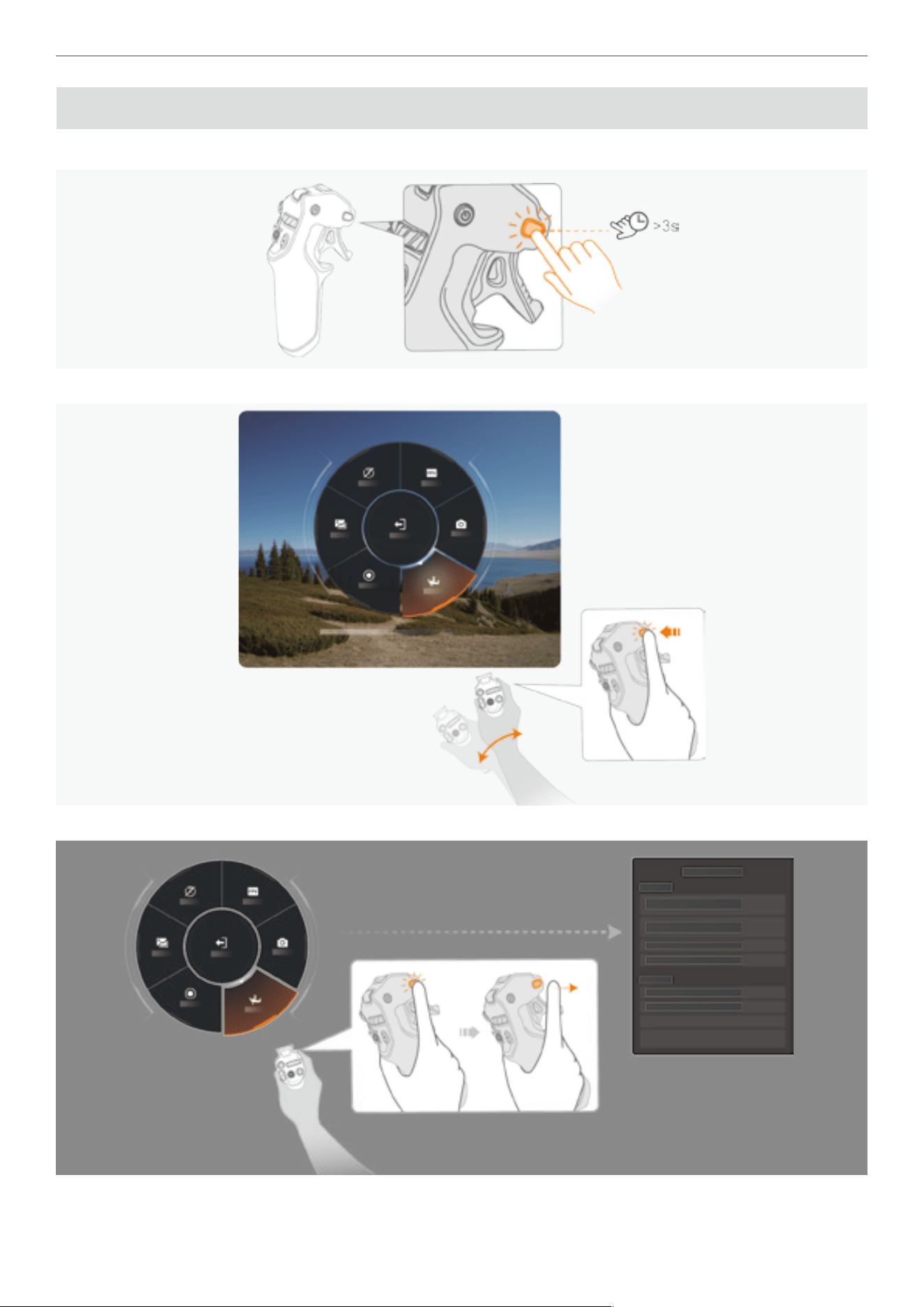
68
Antigravity A1 User Manual
©
2026 Antigravity All Rights Reserved
Quick Menu
After power on the Vision Goggles battery, press and hold the menu button to access the quick menu.
1. While holding the menu button, swing your arm to move dial to select options on the quick menu.
2. Rotate the dial to the desired menu option, release the menu button to select the current option.
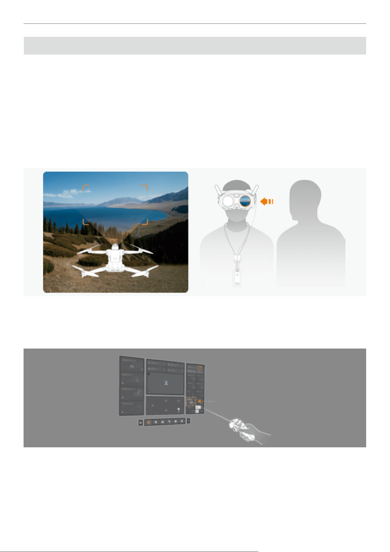
69
Antigravity A1 User Manual
©
2026 Antigravity All Rights Reserved
Outer Display
Outer Display Overview
The outer display, as an important interactive interface of the Vision Goggles, possesses the following key functions:
� Share the ight perspective
� Personalized display
Sharing Flight Perspective
As an essential interactive interface of the Vision Goggles, the outer display screen enables the function of sharing the
ight perspective, allowing users to share the visuals of their ight and experience ying moments with others.
� During the ight, the out display will display the real-time image information transmitted by the drone. Spectators
near the operator can watch the ight visuals on the secondary screen and share the ying experience together.
Personalized Display
� Supports personalized display function, allowing users to choose different standby videos or images through the
"Outer Display and Halo" option in the Vision Goggles menu. The location of this setting is shown in the following
gure.

70
Antigravity A1 User Manual
©
2026 Antigravity All Rights Reserved
Video Playback
The Vision Goggles supports video playback on various format, including 360-degree video. It bring a immersive
viewing experience to the users.
1. Insert the MicroSD card that contains the video footages that you wish to view.
2. Power on the Vision Goggles and enter the Vision Goggles menu, access to the "Album" page at the main menu
and locate the footages that you wish to play.
3. Select the footages via the virtual beam and pull the throttle trigger to conrm your selection, then the video play
back begins.
Exporting the Footages from Vision Goggles
Storage
Vision Goggles have built-in storage and support external memory cards. To learn how to install an external card, refer
to the “Vision Goggles Overview” on page 60. Recorded videos footages are saved to the built-in storage by
default, but users can select their preferred storage location in the menu.
Exporting Footages from Vision Goggles
1. Power on the Vision Goggles.
2. Connect the Vision Goggles to a computer using a USB-A to USB-C data cable, and export the les as prompted.
Exporting Footages from SD Card
1. Turn off the Vision Goggles.
2. Use your ngernail or a at object to press inwards on the MicroSD card until it pops out.
3. Use a card reader you preferred to read and export the recorded video footages from the MicroSD card.
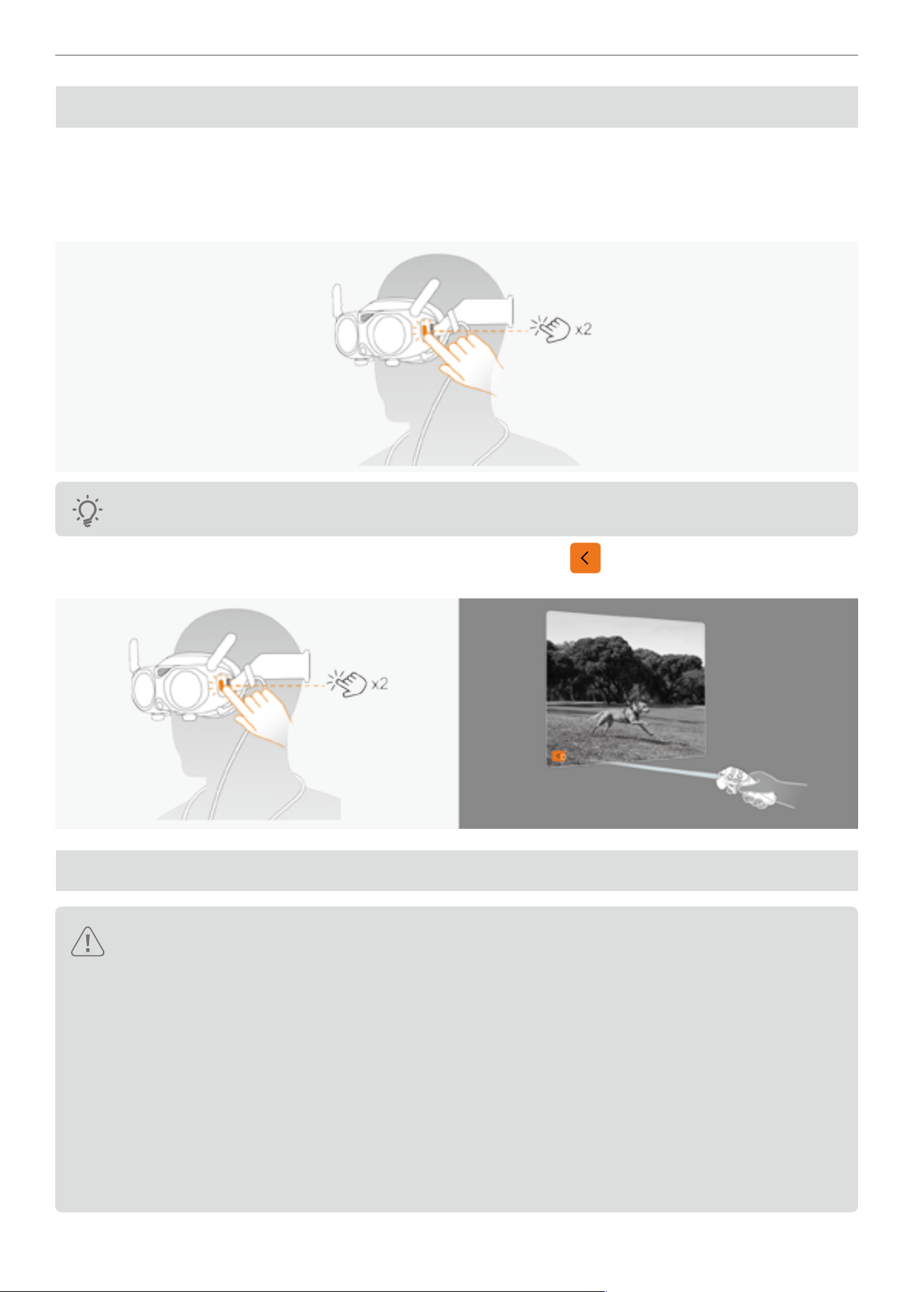
71
Antigravity A1 User Manual
©
2026 Antigravity All Rights Reserved
Video See-Through
The Vision Goggles is equipped with a forward-facing camera, allowing users to view their surroundings without
removing the goggles. Follow the instruction below to use this feature:
1. Press twice on the Home button on the left side, the Vision Goggles will project the user's surroundings in black and
white images inside the goggles.
The images from video see-through are displayed in black and white, which is normal.
2. Press twice on the Home button to exist see-through mode, or tap on the button via the virtual beam to return
to the Vision Goggles menu.
Vision Goggles Safety Notices
� Before using the Vision Goggles, always wipe the lenses inside with the ofcial lens cleaning cloth
provided to ensure the best user experience.
� Do not use alcohol or other solvents to clean the optical lenses of the Vision Goggles. It is recommended
to use the ofcial lens cleaning cloth.
� If the degree of vision correction exceeds 200 to 500 degrees, users will need to separately purchase
lenses to suit their needs.
� It is recommended to refer to the scale range on the lens when wearing the Vision Goggles for the rst
time, manually adjust the appropriate degree, and then ne-tune when wearing them.
� Be careful when adjusting the diopter adjustment knob as there is a limited range of adjustment. Do not
exceed the range to avoid damage.
� Avoid direct sunlight on the lenses of the Vision Goggles as it may cause damage to the lenses.
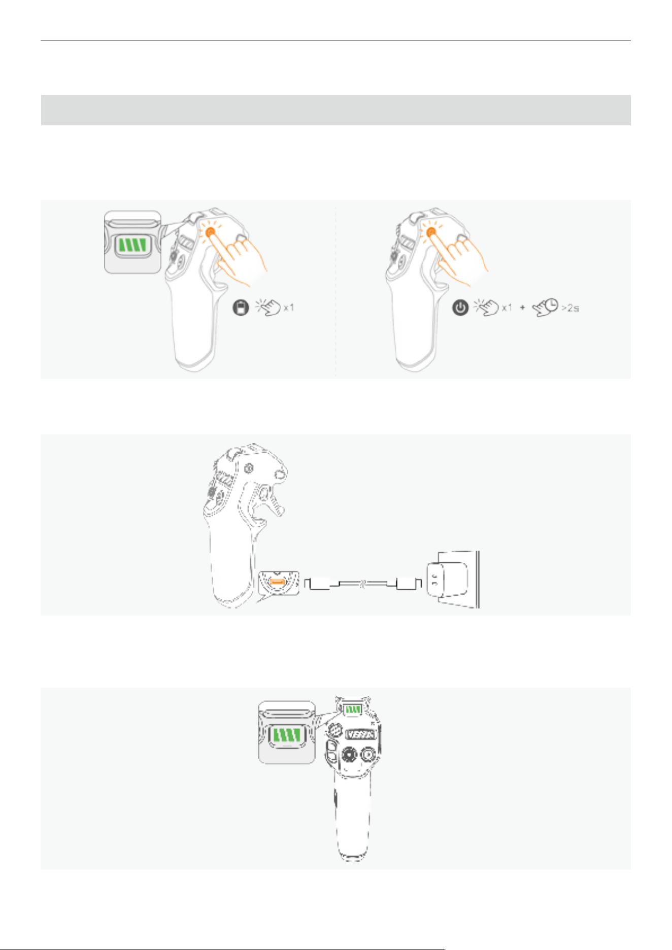
72
Antigravity A1 User Manual
©
2026 Antigravity All Rights Reserved
Grip Motion Controller
Power Button and Battery Level Indicator
Powering On/Off the Grip Motion Controller
� Press once on the power button to check the current battery level.
� Press once on the power button and hold it for two seconds to power on or off the Grip Motion Controller.
Charging the Grip Motion Controller
The charging port is the end of the handle. Connect a charging cable to this port to charge the controller.
Battery Level Indicators
Apart from displaying the current battery level, the indicator also serves as the system indicator to display information
such as linking status and so on.
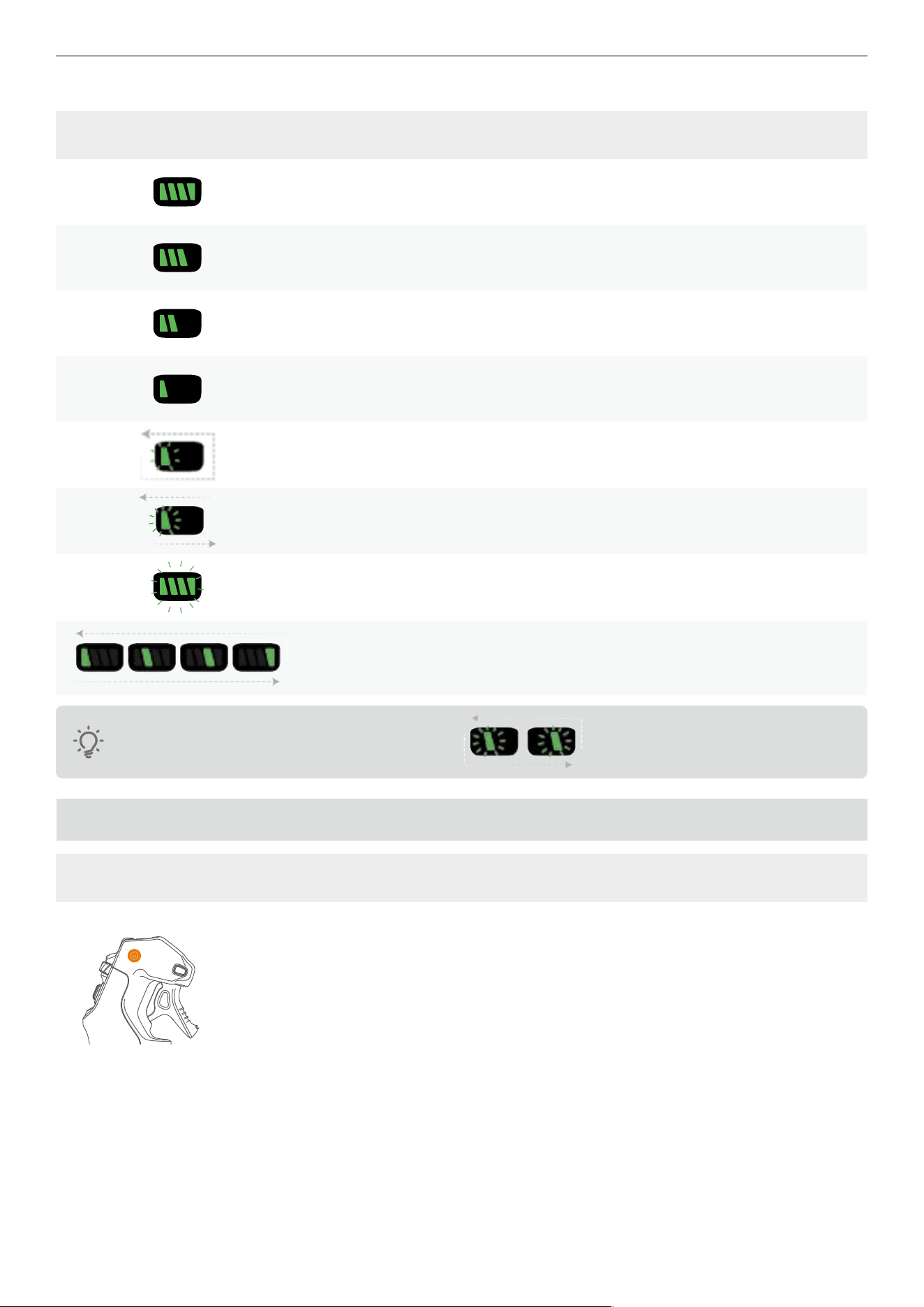
73
Antigravity A1 User Manual
©
2026 Antigravity All Rights Reserved
The blinking pattern of the indicators is as following.
Blinking Patter Status
Four green bars indicate that battery level is approximately 100 - 75%.
Three green bars indicate that battery level is approximately 75 - 50%.
Two green bars indicate that battery level is approximately 50 - 25%.
One green indicates that battery level is approximately 25 - 15%.
Slow blinking of one green bar indicates that battery level of 15 - 5%.
Fast blinking of one green bar indicates that battery level of 5 - 0%.
Blinking green LEDs indicates the controller is searching for the drone.
Loop playback indicates it is in the linking state.
The middle section of the LED indicators blinking ( ) indicates that the Grip Controller is
updating its rmware.
Grip Motion Controller Buttons
Button Functions
Power Button
Power on/off
� Press once, and the hold to power on or off the Grip Motion Controller. Hold for more
than 10 seconds to force shutdown the Grip Motion Controller.
Linking
� Power on and press and hold for four seconds to start linking.
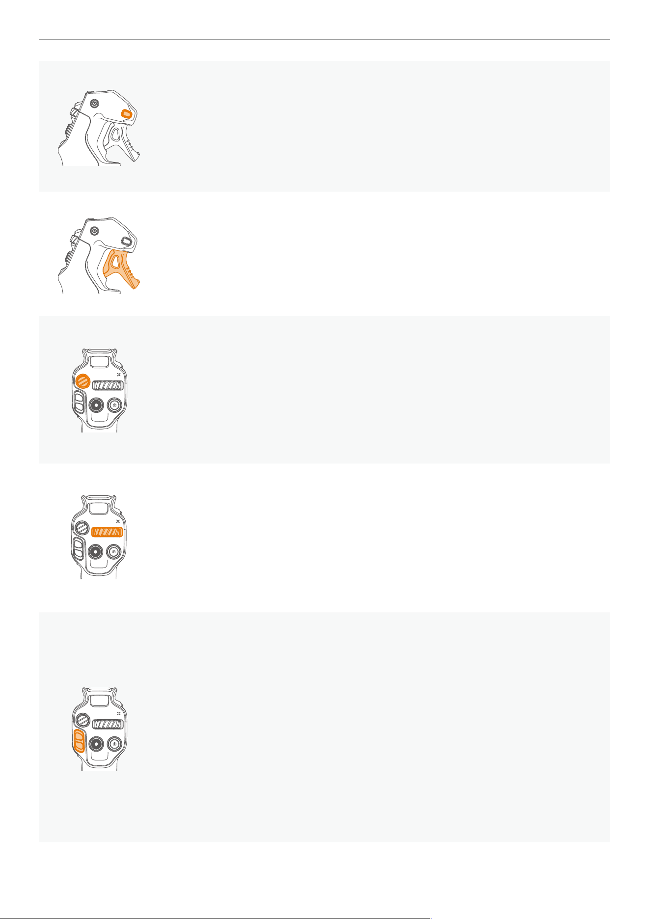
74
Antigravity A1 User Manual
©
2026 Antigravity All Rights Reserved
Menu Button
Short press or long press to enter the general menu or quick menu of the Vision Goggles.
General Menu
· When linked to the goggles, press once to enter the general menu, press again to exit.
Quick Menu
· Press and hold to enter the quick menu. Release to conrm the selection and exit.
Throttle Trigger
In Flight Menu
� Press inward or release the button to accelerate or decelerate the ight speed of your
drone.
In the General or Quick Menu
� Press once to conrm the selection, press and hold to scroll up and down.
Emergency Brake/ RTH Button
This button manifests differently according to the ight status of the drone.
Mid-air
� While the drone is in mid-air, press once briey to make the drone stop immediately.
RTH
� While the drone is in mid-air, press and hold to initiate RTH. The drone will begin to
return to the recorded Home point.
360 Dial Button
When drone is grounded
� Turn left or right to adjust the camera view.
While Hovering
� Turn left or right to change the heading of the drone.
While view in the Vision Goggles
� Press inward to recenter the perspective of the heading of the drone.
Flight Slider
Use the slider to take off or land your drone and adjust the ight altitude.
Unlocking Motors
� Push the ight slider upwards in two short bursts to unlock the motors, putting them into
idle mode. Push the ight slider twice to stop the motors.
Taking Off
� While the motors are unlocked, push the slider continuously for more than two seconds
to allow the drone to ascend. The drone will take off and hover at 1.2m. During the
ight, push the slider upwards or downwards to adjust the ight altitude of the drone.
Landing
� Push the slider downwards to allow the drone to descend. The drone will slowly land on
the recorded Home point and stop the motor.
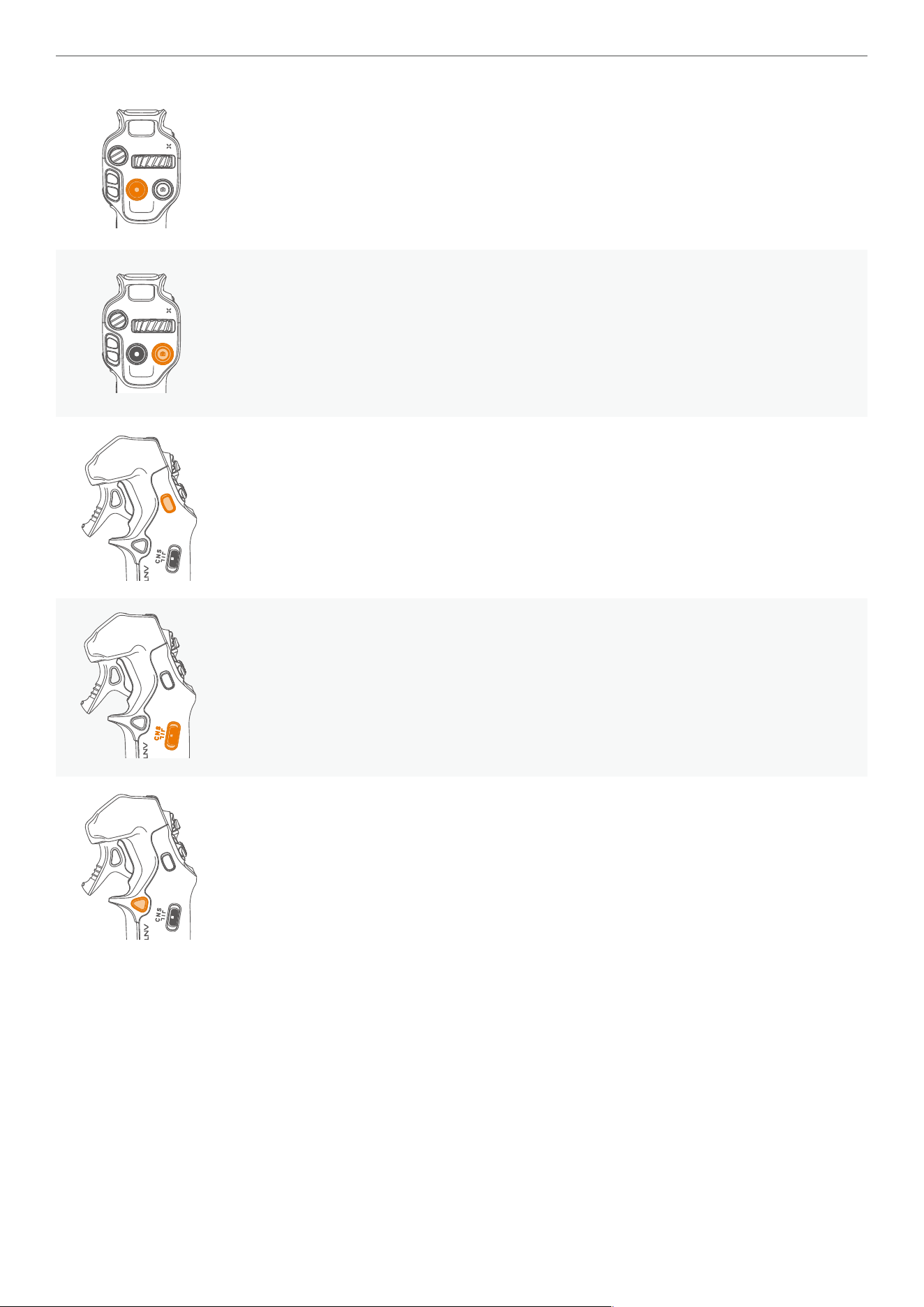
75
Antigravity A1 User Manual
©
2026 Antigravity All Rights Reserved
Record Button
By default, press and hold to switch to video recording mode. Press once to start
recording, press again to stop recording.
Shutter
By default, press and hold to switch to camera mode. Press again to take the picture.
Customize C2 Button
Landing Gear
� Press twice to lower or retract the landing gears.
Customize
� Customize the function of the C2 button through the general menu.
Flight Mode Toggle
Toggle to switch the ight mode into the follow three ight modes:
� N (Normal) mode
� S (Sport) mode
� C (Cine) mode
Customize C1 Button
Tracking
� When drone is in mid-air, long press the button to select the tracking subject from the
live view.
Landing Light
� When drone is in mid-air, short press the button to turn on the landing light.
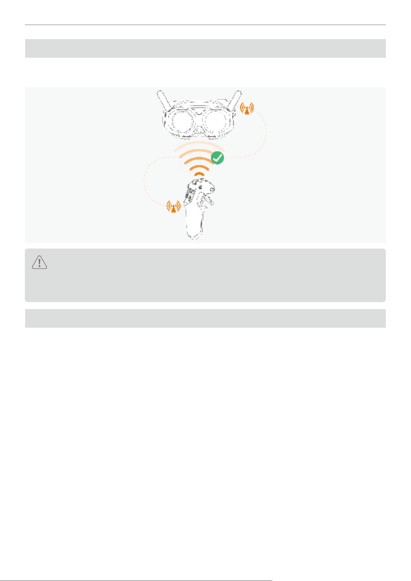
76
Antigravity A1 User Manual
©
2026 Antigravity All Rights Reserved
Grip Motion Controller Signal
For optimal transmission quality, ensure there are no obstacles between the Grip Motion Controller and the Vision
Goggles.
� It is recommended to use the motion controller in an open and unobstructed environment, ensure there
is no obstacles between the motion controller and the drone.
� Ensure that there are no other radio transmission devices operating adjacent to the motion controller, as
they may create interference.
Alert Sounds
Low Battery Alert
When the motion controller's battery is low, an alarm will sound. It can be canceled by pressing once the power button.
However, the alarm cannot be muted when the battery level is below 5% in order to prompt the user to return and
land.
RTH Alert
The Grip Motion Controller will beep alerts while the drone is in the RTH process. Note that this beeping alert cannot
be muted as long as the drone is still in RTH state.
Antigravity App
Connect the Vision Goggles to the mobile device, launch the Antigravity app to enter the home page. The home page
includes the following major features:
� Explore aerial hot spots around your area. Understand the concept of ight protection areas, policies and other
information, and watch video tutorials and user manuals for product knowledge.
� Brows your footages from albums on your drone or your mobile devices, or use Studio for creative video editing and
sharing them on the social media.
� Log in to view account information and ight records.
� Other functions, such as rmware updates, aircraft searching, Find My Drone.
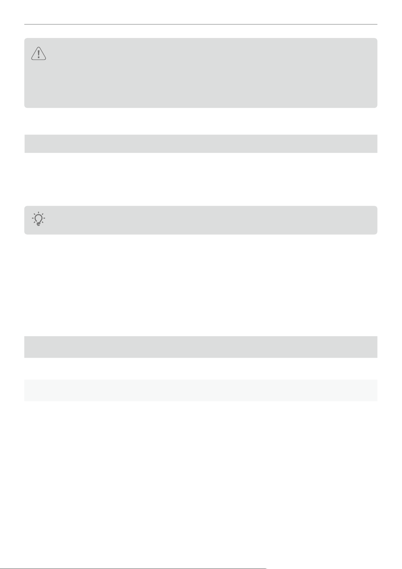
77
Antigravity A1 User Manual
©
2026 Antigravity All Rights Reserved
� Before using the Antigravity app, ensure your mobile device is fully charged.
� Cellular data package is required while using the Antigravity app, contact your carrier for pricing.
� Read all safety guidelines and disclaimers from the app and understand local regulations.
� Before using the Antigravity App, you must read and agree the terms of use and privacy policy, please
read and understand the terms and policies.
Intelligent Flight
Deep Track
Deep Track
The Deep Track modes of the A1 drone allows the drone to automatically follow the selected shoot objects while
maintaining a safe distance from the objects. This section provides information about the basic operation of the Deep
Track mode and its safety notice during the usage of this mode.
The drone cannot automatically start recording the video while the drone is tracking the object. Users will
need to manually start recording the video.
Auto Mode
The drone maintains a specic distance and ight altitude from the manually selected object while ying. And the
acceleration direction and ight direction of the drone always follows the direction of the tracked object.
Circle Mode
The drone maintains a specic distance and ight altitude from the manually selected object while ying. Additionally,
the acceleration and ight direction of the drone always follow the direction of the tracked object. Different from the
general mode, the drone will circle around the tracked object in the specied direction while tracking.
Optimal Tracking Distance
Tracking Object People Vehicle or Boat
Horizontal Distance 4 - 10 m (13 - 32 ft) 6 - 30 m (19 - 104 ft)
Height 2 - 10 m (7 - 32 ft) 6 - 30 m (19 - 104 ft)
The drone will adjust its distance to the tracked object when ying beyond the recommended detection range. Users
may use the grip controller to adjust the aforementioned parameters when the drone is operating within the detection
range.
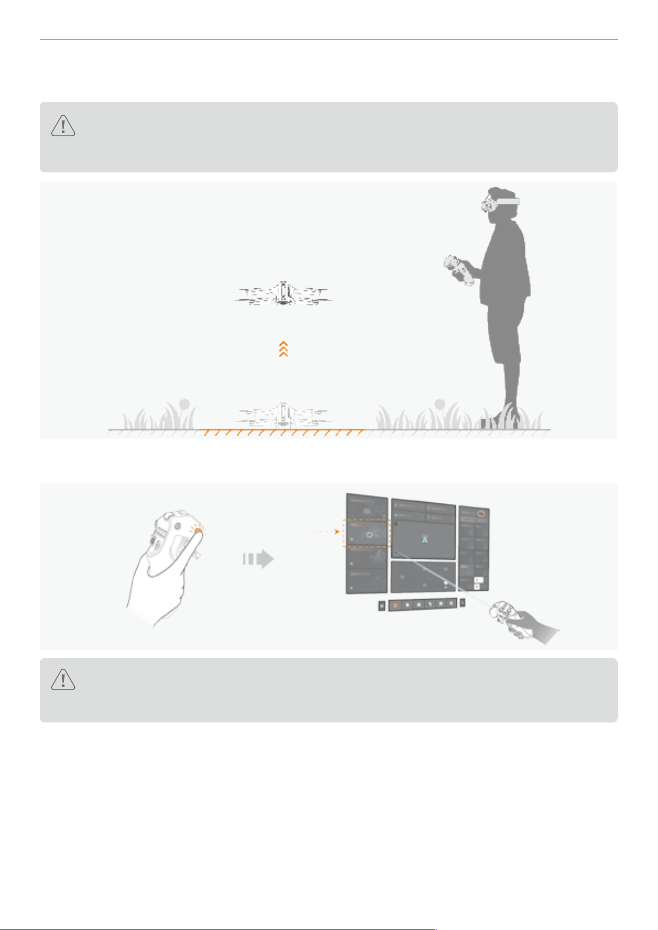
78
Antigravity A1 User Manual
©
2026 Antigravity All Rights Reserved
Using Deep Track
1. Take off your drone in an open area, and allow the drone to hover at a safe altitude.
In case of obstacle avoidance is unavailable due to the external environmental conditions (such as
operating at night time or low light), users must read and conrm the warning message in the countdown
prompt before engaging the Deep Track feature.
2. Press the Menu Button on the Grip Controller to enter the ight menu of the Vision Goggles. Select the Deep Track
option by using the virtual beam.
Drone cannot start tracking an object if it is in photo mode. Ensure the drone is in video shooting mode
before using Deep Track. Refer to “Grip Motion Controller Buttons” on page 73 for instructions on
how to switch between photo and video modes.
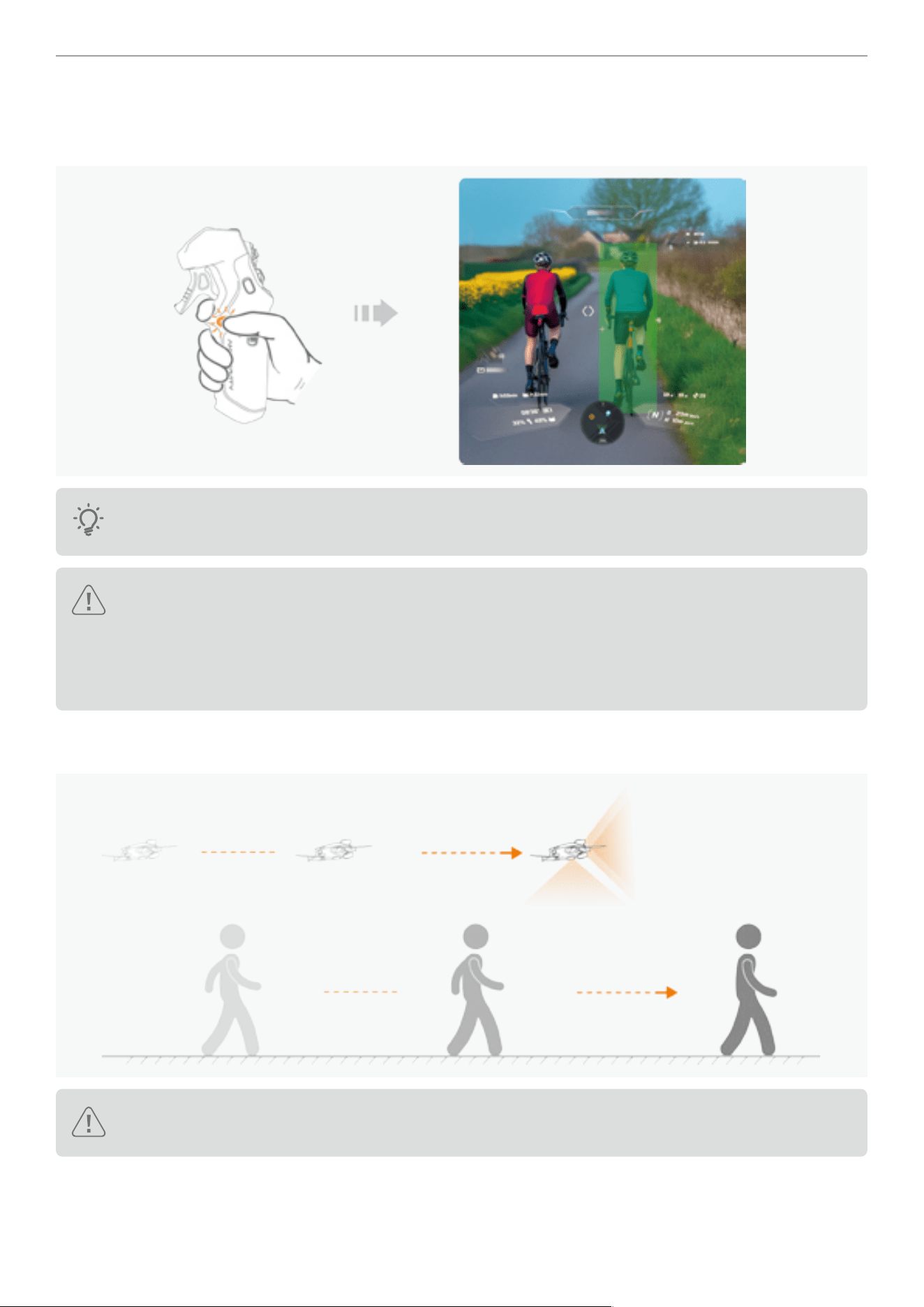
79
Antigravity A1 User Manual
©
2026 Antigravity All Rights Reserved
3. After activating Deep Track mode, press the C1 button on the Grip Controller and drag the green selection box on
the screen to select the object you wish to track. Release the C1 button to conrm the selection, and then the drone
will start tracking the object.
You can also long press the C1 button on the Grip Controller to activate the Deep Track mode. Be aware
of the count down progress displays on the screen.
Caution: User must read and conrm a warning prompt from the Vision Goggles if the obstacle avoidance
system become unavailable due to the external environment constraints. Automatic tracking will only start
after the user chooses to proceed in spite of the warning.
The drone might approach the tracked object during the object selection stage. Hence, we should always
maintain a safe distance between the object and the drone.
4. After tracking has started, the drone will begin following the object as it moves, maintaining the pre-set following
direction and distance. Users may start recording while the tracking is in progress.
Caution: During the tracking, the drone will not respond to the swing movements from the users; however,
the user can still control the cruise speed and the ight altitude of the drone.
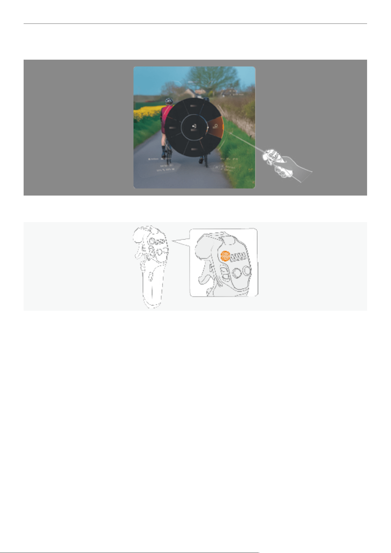
80
Antigravity A1 User Manual
©
2026 Antigravity All Rights Reserved
5. The default tracking direction to the object is “Rear”. If you wish to switch the track direction during the tracking
process, long press C1 button on Grip Controller to bring up the quick access dial and adjust the tracking direction.
6. Abort the tracking by pressing the Brake button on the Grip Controller at any time to ensure safety. At this time, the
drone will hover at the current altitude awaiting further instructions from the users.
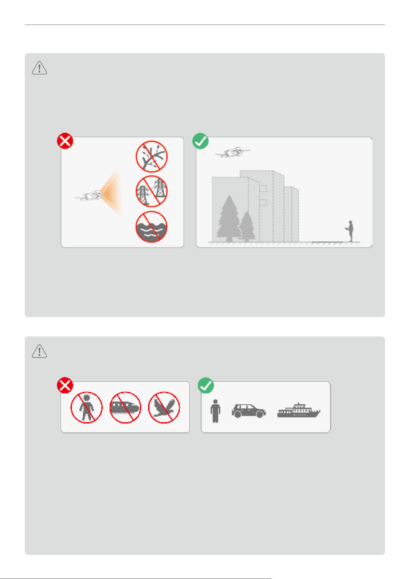
81
Antigravity A1 User Manual
©
2026 Antigravity All Rights Reserved
General Safety Notices for Deep Track
�
Be sure to use the Deep Track feature in an open, well-lit environment. Otherwise it may pose danger to others.
� The obstacle avoidance of the drone remains functional during the tracking process, still capable of
detecting obstacles in the direction of the drone’s heading. However, the drone cannot detect obstacles
at the rear or sides of the drone. Fly with caution in these scenarios.
� DO NOT use the Deep Track feature in areas where branching or ne objects (such as tree branches,
power lines), transparent objects (such as water, glass), or monochrome surfaces (such as white walls)
are present, as it may affect the ight safety of your drone.
� Be aware of the availability of obstacle avoidance by checking the status update on the icon and prompt
warning message. Stop using Deep Track when obstacle avoidance becomes unavailable.
� Stay vigilant of the surrounding people, animals and vehicles during the tracking.
� Do not use the Deep Track feature when environmental and external constraints are present. Refer to
“Obstacle Avoidance and Landing” on page 43.
� Do not use the Deep Track feature near the ight restriction areas.
Safety Notices for Selecting Object in Deep Track
� Before activating the Deep Track feature, prioritize privacy considerations and comply with local laws.
� Users should only track vehicles, boats, or personnel (excluding children). using the drone to track other
moving objects (such as RC car or RC boat), do so cautiously and at your own risk.
� The drone cannot track a subject that has undergone a shape-shifting process (such as people jumping
and squatting). Users should y with caution in this scenario.
� Be extra caution when using Deep Track feature in the following scenarios:
- If the tracked object is moving on the uneven surface.
- If the tracked object undergoes signicant shape-shifting while moving.
- If the line of sight to the object has been blocked for an extended period.
- If the texture and color of the object lack distinction against the surrounding area.
� Do not proceed with tracking if the selected object is not identied as a human, vehicle or boat.
� The tracked object might deviate if the originally selected object is overlapping with another object.
� In case the tracking object is lost due to a blocked line of sight, the drone will prompt user to re-select the
tracking object.

82
Antigravity A1 User Manual
©
2026 Antigravity All Rights Reserved
Sky Genie
Introduction to Sky Genie
The Sky Genie features a collection of pre-dened ight paths that can be automatically executed by the drone to
allow users to produce professional cinematic footage with minimal intervention. This intuitive feature empowers users
to replicate the complex cinematic move with just a single tap.
� Only use the Sky Genie feature in a clear and unobstructed environment. Avoid tall buildings or obstacles
near the ight path, and ensure no other individuals, animals, or obstacles are present on the route
besides the selected subject being lmed.
� The head track perspective and the drone’s heading do not overlap while executing the Sky Genie ight
path. Be aware that clearance of the ight path is required, and be ready to take control of the drone
when necessary.
� Do not activate the Sky Genie in the following scenarios:
- When the selected subject is obstructed for an extended period and is not visible within the live view
of the Vision Goggles.
- When the selected subject is beyond of line of sight, hence it prevents the users to observe the ight
status of the drone.
- DO not attempt to select the subject that is in mid air.
- When the texture or the color of the subject being lm is too similar to the surrounding environment.
- DO NOT use the Sky Genie in environments that are too bright or too dark.
- DO NOT use the Sky Genie when the selected subject is in close proximity to the tall buildings,
resulting in poor GNSS signals.
� DO NOT use the Sky Genie feature in areas where branching or ne objects (such as tree branches,
power lines), transparent objects (such as water, glass), or monochrome surfaces (such as white walls)
are present, as it may affect the ight safety of your drone.
� While obstacle avoidance can enhance safety when using the Sky Genie, it is not a substitute for the
user’s discretion regarding ight safety. Users must remain alert and be prepared to take control of the
drone from the Grip Controller to safeguard ight safety.
� Before activating the Sky Genie feature, prioritize privacy considerations and comply with local laws.
The following shooting patterns are supported by Sky Genie:
Orbit The drone circles the subject and cruises at the pre-set ight parameters.
Fly Away
The drone ies upwards and gradually y away from the subject to reveal the
surroundings.
Ascend The drone ies direct above the subject and moves upwards.
Spiral Ascent The drone ies upwards and moves away from the subject as it spiral around.
Oval Orbit
The drone is circle the subject in a titled and stretched circle trajectory. It rst y
toward the back of the subject then moving away.
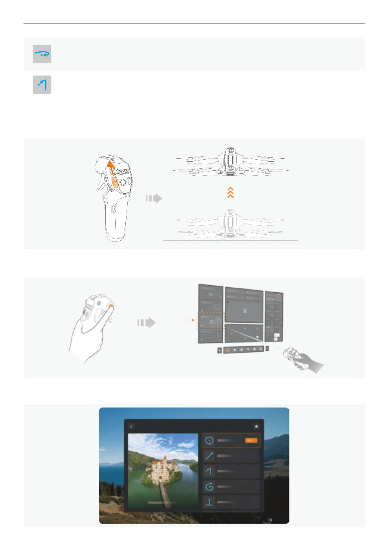
83
Antigravity A1 User Manual
©
2026 Antigravity All Rights Reserved
Arc Shot
The drone rst approaches the subject in a straight line, then banks a turn around
the subject before resuming a straight ight path. Users may choose either
clockwise or counterclockwise as the rotation direction.
Antigravity Line
The drone approaches and ies past the subject in a straight line, while the head
tracking view is rotated 180° with the subject framed at the center.
Using Sky Genie
1. Find an open, unobstructed area with at ground to take off your drone. It is recommended to ascend your drone to
an safe altitude (3 meters above the take off site) before activate the Sky Genie feature.
2. Press once the Menu Button on the Grip Controller to enter the ight menu of the Vision Goggles. Select Sky Genie
by using the virtual laser beam.
3. Select the desired Sky Genie shot option after entering the sub menu. You may preview the demonstration of the
Sky Genie shot in the sub menu section as well.
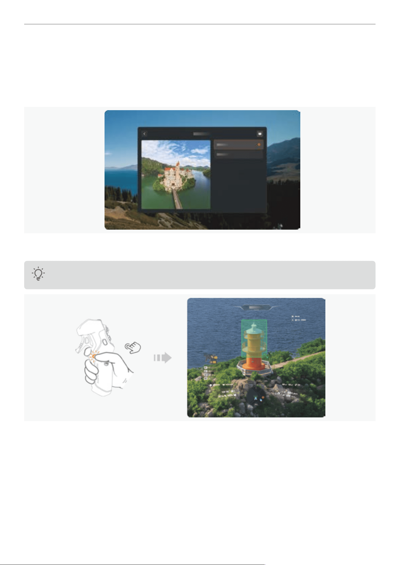
84
Antigravity A1 User Manual
©
2026 Antigravity All Rights Reserved
4. While in this page, user can also selection the Vision Goggles view perspective during the Sky Genie maneuver
was executing. The users may select one of the two view perspective:
- Sky Genie View
- Free Motion View
In the Sky Genie View, the user’s perspective is in sync with the Sky Genie maneuver effect, while the Free Motion
view allows user to disassociate the viewing perspective from the Sky Genie maneuver.
5. Press and hold the C1 button to select the subject that you want to lm. Release the C1 button to conrm the
selection. A green target box will frame the subject if the drone has successfully recognized the subject.
The drone might automatically adjust its position in order to obtain an optimal viewing angle to capture the
subject. Remain calm if the drone is moving while selecting the subject.
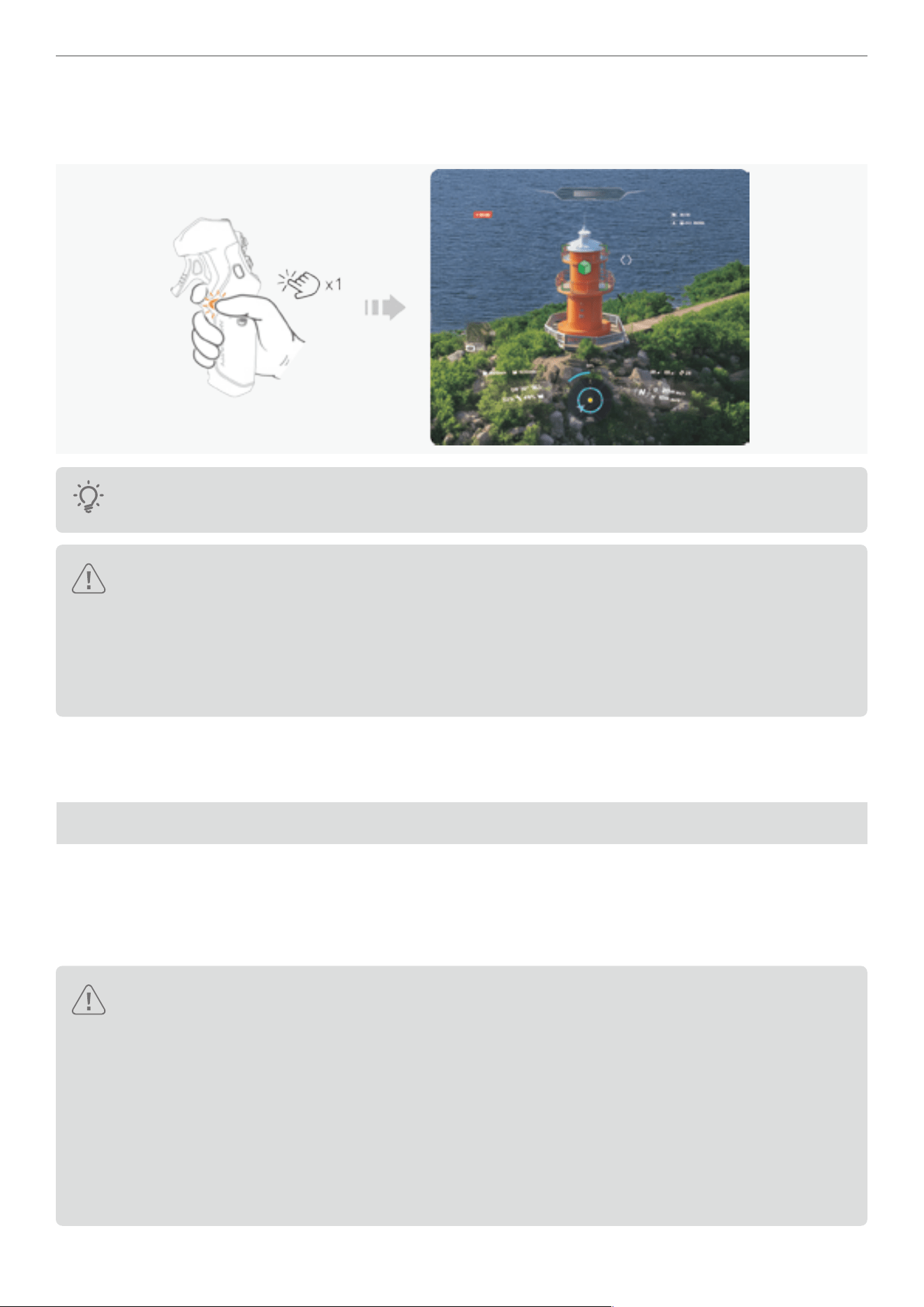
85
Antigravity A1 User Manual
©
2026 Antigravity All Rights Reserved
Press the C1 button again to start executing the selected Sky Genie shot. The drone will automatically execute the
ight route and start recording the video footage. After completing the ight route, the drone will return to the starting
point and hover in place and await input from users.
To achieve the best result in selecting the subject, focus on selecting the main body of the subject and
reduce the selection of the surrounding background.
� After the subject is selected, users can press once on the C2 button to adjust ight route parameters,
such as the distance or the rotation directions. Adjust these parameters to suit your needs. Meanwhile,
the estimated ight route and ight time will be displayed to help you assess the ight.
� Upon your access to the Sky Genie page, a countdown prompt might be displayed to alert users that
the current lighting condition will prevent obstacle avoidance from working properly. You must read and
conrm the selection before proceeding with the using the Sky Genie.
6. While the drone is in executing Sky Genie shot, users can press and hold the C2 button on the Grip Controller to
exit the current ight route. Meanwhile, users can also abort the ight route at any moment by pressing once on the
Brake button on Grip Controller.
Sky Path
Introduction to Sky Path
In Flight Path mode, users can construct a ight route by setting way points while the drone is in ight. After the ight
route has been established and saved, the drone can then automatically retrace the ight route and record video
footages for multiple times.
Caution:
� Only use the Flight Path feature in an open, unobstructed area, ensure there is no visible tall structure at
the surroundings before each ight. Meanwhile, make sure there is no individual, animal or other obstacle
on the ight path.
� DO NOT attempt to use Flight Path feature in one of the following scenarios:
- When GNSS signal is weak.
- When there are tall buildings or structures on the planned ight path.
- DO NOT use Sky Path in environments that are too bright or too dark.
- When the texture or the color of the subject being lm is too similar to the surrounding environment.
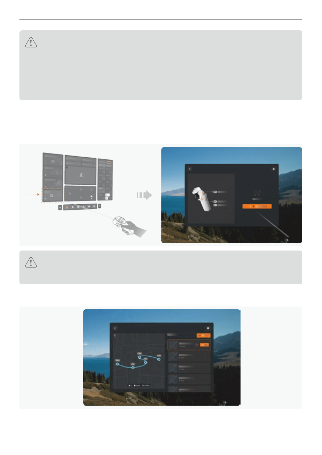
86
Antigravity A1 User Manual
©
2026 Antigravity All Rights Reserved
� DO NOT use the Sky Genie feature in areas where branching or ne objects (such as tree branches,
power lines), transparent objects (such as water, glass), or monochrome surfaces (such as white walls)
are present, as it may affect the ight safety of your drone.
� While obstacle avoidance can enhance safety when using the Sky Genie, it is not a substitute for the
user’s discretion regarding ight safety. Users must remain alert and be prepared to take control of the
drone from the Grip Controller to safeguard ight safety.
� Before activating the Sky Path feature, prioritize privacy considerations and comply with local laws.
Using Sky Path
1. Creating Flight Route
Access to the Flight Route sub menu from the main menu of the Vision Goggles on the left. Click on the orange button
on the right to start creating a new ight route.
Caution: Upon your access to the Sky Path page, a countdown prompt might be displayed to alert users
that the current lighting condition will prevent obstacle avoidance from working properly. You must read
and conrm the selection before proceeding with the Sky Path.
Apart from creating ight routes, users can also select and execute previously saved ight routes in this window.
Additionally, users can set up the in-ight perspective for the selected ight routes that are to be run.
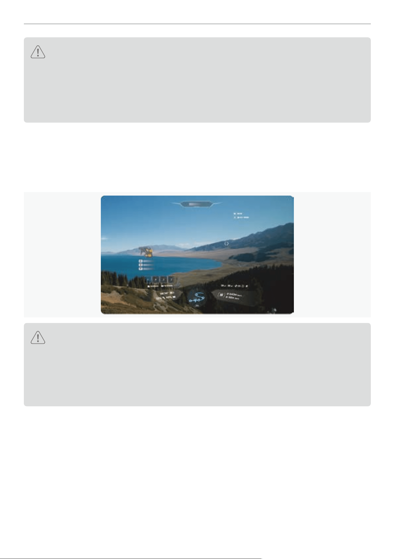
87
Antigravity A1 User Manual
©
2026 Antigravity All Rights Reserved
Cautions:
� Find an open and unobstructed ight site and take off your drone before creating a new ight route.
� Users can rerun the previously saved ight path under the condition that the ight must be carried out at
the same Home point and under the same weather conditions. Failure to do so might result in not being
able to safely execute the ight path.
� Ensure obstacle avoidance is available for use before using Sky Path function to prevent potential ight
safety accidents.
2. Adding Waypoints
Take off the drone and maneuver it to the starting point of the desired ight path. Ensure the GNSS signal is strong.
After conrming the heading and current position of the drone, press once on the C1 button to add the current location
as the waypoint. Once completed, the waypoint will be added to the queue at the bottom of the screen. You can now
proceed with the ight to the next location and repeat the previous operation. Additionally, press the C2 button to
delete the previous waypoint.
Cautions:
� While creating waypoints during the ight, users must ensure that the GNSS signal is strong at all
times. Waypoints cannot be created when the GNSS signal is weak. Failure to monitor the GNSS signal
strength during the waypoint creation process may pose safety risks when executing the ight path.
� The actual ight path between waypoints is in a curved shape, hence there exists a height difference in
between. Users must remain vigilant while the drone traverses each of the waypoints and regain control
of the drone if necessary.

88
Antigravity A1 User Manual
©
2026 Antigravity All Rights Reserved
3. Conrming Flight Path
After setting all waypoints, press and hold the C1 button to nish setting the waypoints. We will then enter the waypoint
conrmation page.
On this page, users can add or delete waypoints, adjust the waypoint queue, and also set the drone’s ight speed and
smoothness while executing the ight path. After ne-tuning the parameters, users can select “Save and Execute”.
The drone will adjust its heading and start ying from the current position to the starting point of the ight path, and
proceed with executing the ight path.
Caution:
� The position and altitude difference between the starting point and the endpoint of the ight path should
not be too large. Otherwise, the battery level might not be sufcient to support the long-haul ight and
could affect the possibility of safely returning your drone.
� Before executing the ight path, make sure the obstacle avoidance is turned on, otherwise the drone
might not be able to by-pass the obstacles during the ight.
4. Executing the Flight Route
When the drone is executing its ight path, the mini map on the Vision Goggles will display the preset route. Users can
monitor the status of the route execution through the mini map.

89
Antigravity A1 User Manual
©
2026 Antigravity All Rights Reserved
5. Exiting the Flight Route
Users can abort the current ight route by long-pressing the C2 button. At the same time, users can also exit the ight
route by pressing once on the emergency brake button. The drone will hover in place and awaits commands.
� The drone will automatically abort the current ight route and hover when the obstacle avoidance system
becomes unavailable. User’s discretion is required.
� As soon as an obstacle is detected on its ight path, the drone will immediately abort the ight and hover.
Product Specification
A1 Drone
Drone
Model DE001
Maximum Takeoff Weights
249 g (0.548 lbs) with Standard Flight Battery
291 g (0.642 lbs) with High-Capacity Flight Battery
Dimensions
Folded
:
141.3 mm × 96.2 mm × 81.4 mm
5.56 inches x 3.79 inches x 3.21 inches (L×W×H)
Unfolded
:
308.6 mm × 382.3 mm × 89.2 mm
12.15 inches x 15.05 inches x 3.51 inches (L×W×H)
Max Ascent Speed C mode: 3 m/s N mode: 6 m/s S mode: 8m/s
Max Descent Speed C mode: 3 m/s N mode: 6 m/s S mode: 8m/s
Max Horizontal Speed* C mode: 3 m/s N mode: 12 m/s S mode: 16 m/s
Max Takeoff Altitude
4,000 m or 13,123 ft (with Standard Flight Battery)
3,000 m 9,842 ft (with High-Capacity Flight Battery)
Max Flight Time
Approx. 24 mins (with Standard Flight Battery)**
Approx. 39 mins (with High-Capacity Flight Battery)**
Max Wind Resistance 10.7 m/s or 23.9 mph
Operating Temperature -10°C - 40°C (14°F - 104°F)
Global Navigation Satellite System BDS + GPS + Galileo
Hovering Accuracy Range (GNSS) Horizontal: ±0.5 m, Vertical:
±0.5 m (GNSS signal strong and open areas)
Hovering Accuracy Range (Vision)
Horizontal: ±0.1 m, Vertical: ±0.1 m (Well-lit environment with distinct
surface texture)
Internal Storage 20 GB

90
Antigravity A1 User Manual
©
2026 Antigravity All Rights Reserved
Supported Storage Card MicroSD
List of Recommended Storage Card
SanDisk Extreme PRO 64GB V30 U3 A2 microSDXC
SanDisk Extreme PRO 128GB V30 U3 A2 microSDXC
SanDisk Extreme PRO 256GB V30 U3 A2 microSDXC
SanDisk Extreme PRO 512GB V30 U3 A2 microSDXC
SanDisk Extreme PRO 1TB V30 U3 A2 microSDXC
Lexar Silver Plus 64GB A2 V30 microSDXC
Lexar Silver Plus 128GB A2 V30 microSDXC
Lexar Silver Plus 256GB A2 V30 microSDXC
Lexar Silver Plus 512GB A2 V30 microSDXC
Lexar Silver Plus 1TB A2 V30 microSDXC
Kingston CANVAS Go! Plus 64GB A2 V30 microSDXC
Kingston CANVAS Go! Plus 128GB A2 V30 microSDXC
Kingston CANVAS Go! Plus 256GB A2 V30 microSDXC
Kingston CANVAS Go! Plus 512GB A2 V30 microSDXC
Kingston CANVAS Go! Plus 1TB A2 V30 microSDXC
Ground Noise Level
Hovering: 75.0 dB (A)
In Flight at 3 m/s: 73.0 dB (A)
Constant Noise Level
Hovering: 74.0 dB (A)
In Flight at 3 m/s: 72.0 dB (A)
360 Camera
Sensor Size 1/1.28 inch
Aperture F2.2
ISO Range 100 - 6400
Shutter Speed
Video: 1/8000
Photo: 1/8000 - 1/2
White Balance 2,000K - 10,000K
Max Image Size
Approx. 55MP (10486 × 5248)
Approx. 14MP (5248 × 2624)
Camera Mode Normal, HDR, Burst, AEB
Video Resolution
8K: 7680 × 3840@30/25/24fps
5.2K: 5248 × 2624@60/50/30/25/24fps
4K: 3840 × 1920@100fps
4K Slo-Mo: 3840 × 1920@30/25/24fps
Video Format INSV, Export via Antigravity app or Studio desktop application.
Photo Format
INSP, Export via Antigravity app or Studio desktop application.
DNG

91
Antigravity A1 User Manual
©
2026 Antigravity All Rights Reserved
Max Video Bitrate 170 Mbps
Video Encode Format H.264, H.265
Supported File System exFAT
Vision and Infrared Senors
Forward
Measurement Range: 0.5 m - 18 m (1.6–59.1 ft)
Effective Sensing Speed: Flight Speed ≤12 m/s (26.8 mph)
FOV: Horizontal 93°, Vertical 105°
Downward
Measurement: 0.3 m - 7.5 m (1.0–24.6 ft)
Effective Sensing Speed: Flight Speed ≤ 6 m/s (13.4 mph)
FOV: Front and Back 107°, Left and Right 90°
Operating Environment
Forward:
Surfaces with discernible patterns and adequate lighting (lux > 15)
Downward:
Surfaces with discernible patterns, diffuse reectivity > 20% (e.g. cement
pavement, stout trees), and adequate lighting (lux > 15)
Video Transmission
Video Transmission System OmniLink 360
Live View Quality 2k@30fps
Transmitter Power (EIRP)
2.4 GHz : < 30 dBm(FCC), < 20 dBm(CE / SRRC / MIC)
5.1 GHz : < 21 dBm(FCC), < 23 dBm(CE)
5.8 GHz : < 30 dBm(FCC / SRRC), < 14 dBm(CE)
Frequency
2400 - 2483.5 MHz*
5150 - 5250 MHz*
5725 - 5850 MHz*
*Availability subject to countries and regions. Local law and regulations
apply.
Max Transmission Distance
(Open, free of interference)
10 km (6.2 mile) (FCC)
8 km (5.0 mile) (SRRC)
6 km (3.7 mile) (CE)
4 km (2.5 mile) (MIC)
*Tested outdoors at 25°C (77°F) in an open, interference-free environment.
Data reects maximum one-way transmission distance without return-to-
home under each standard. Actual performance may vary depending on
environment, usage, and rmware.

92
Antigravity A1 User Manual
©
2026 Antigravity All Rights Reserved
Max Transmission Distance
(Obstructed, with interference)
Low Interference/Buildings: approx. 0.1–0.5 km (0.06–0.31 mi)
Low Interference/Trees: approx. 0.5–3 km (0.31–1.9 mi)
*Tested under FCC standard in obstructed environments with typical low
interference. Used for reference purposes only and provides no guarantee
for actual transmission distance.
Max Transmission Rate 30Mbps
Latency
Approx. 150ms
*Tested in an open, interference-free environment. Actual latency may vary
depending on environmental differences.
Antenna 4 antennas, 2T4R
Wi-Fi
Protocol 802.11a/b/g/n/ac
Operating Frequency
2400 MHz - 2483.5 MHz*
5150 MHz - 5250 MHz*
5725 MHz - 5850 MHz*
* Availability subject to countries and regions. Local law and regulations
apply.
Transmitter Power (EIRP)
2.4 GHz: < 20 dBm(CE / SRRC / MIC / FCC)
5.1 GHz: < 20 dBm(FCC / CE)
5.8 GHz: < 20 dBm(FCC / SRRC), < 14 dBm(CE)
Bluetooth
Protocol Bluetooth 5.0
Operating Frequency 2.400 GHz - 2.4835 GHz
Transmitter Power (EIRP) < 10 dBm
Standard Flight Battery
Model BDE-mini-2360-7.16
Capacity 2360 mAh
Weight Approx. 67.5 g (0.15 lb)
Rated Voltage 7.16 V
Charging Voltage 8.6 V

93
Antigravity A1 User Manual
©
2026 Antigravity All Rights Reserved
Cell Type Li-ion 2S
Energy 16.9 Wh
Charging Temperature Range
5 - 45°C or 41 - 113°F, Charging stops when temperature exceeding 55°C
(131°F)
Charging Time
Single battery: 45 mins***
Three batteries: 2 hours and 15 mins***
High-Capacity Flight Battery
Mode Name BDE-max-4345-7.16
Capacity 4345 mAh
Weight Approx. 108.6 g (0.23 lbs)
Rated Voltage 7.16 V
Charging Voltage 8.6 V
Cell Type Li-ion 2S
Energy 31.11 Wh
Charging Temperature Range
5 - 45°C or 41 - 113°F, Charging stops when temperature exceeding 55°C
(131°F)
Charging Time
Single battery: 60 mins***
Three batteries: 3 hours***
65W GaN Fast Charger
Model ADT-65BDC-P
Input Voltage 90 - 264V (47 - 63Hz)
Output Power 5V ~ 20V@65W / 5A MAX
Operating Temperature -20 ~ 40° C
Battery Charging Hub
Model CINSBANA
Weight Approx 118.5 g

94
Antigravity A1 User Manual
©
2026 Antigravity All Rights Reserved
USB C Input
PPS protocol: 5 - 10V / 5A
PD protocol: 5V - 3A / 9V - 5A / 12V - 5A / 15V - 4A
USB C Output PD protocol: 30W, 15V - 2A / 12V - 2.5A / 9V - 3A / 5V - 3A
Charging Time
Standard Flight Battery:
· Single: 45 mins
· Three: 2 hours 15 mins
High-Capacity Flight Battery:
· Single: 60 mins
· Three: 3 hours
* Sea level and windless.
** Obtained in a controlled environment temperature at 25°C (77°F) , altitude less than 50 m (164 ft), in a wind-free
environment and at the cruising speed of 6 m/s. Camera set at 5.2K/30fps resolution when video recording disabled.
The ight time may vary under different conditions.
*** Charging from the Antigravity 65W GaN Charger via the Antigravity Battery Charging Hub.
Vision Goggles
Flight Goggles
Model DGS001
Weight Approx. 340 g (battery not attached)
Dimensions
Folded: 174 mm × 106 mm × 92 mm (L×W×H)
Unfolded: 200 mm × 106 mm × 115 mm (L×W×H)
Inner Display Size 1.03 inch Micro-OLED
Inner Display Resolution 2560 × 2560
Inner Display Refresh Rate 72 Hz
Interpupillary Distance Range 59 - 72 mm
Diopter Adjustment Range -5.0 D to +2.0 D
FOV
DFOV 90°
HFOV/VFOV 65°
Screen Recording Format INSV
Playback Format MP4, MOV, JPG, PNG, INSP, INSV
See-through FOV HFOV 93°, VFOV 93°, DFOV 115°

95
Antigravity A1 User Manual
©
2026 Antigravity All Rights Reserved
Operating Temperature -10°C to 40°C (14°F to 104°F)
Power Input USB-C with dedicated external battery
Internal Storage Approx. 30 GB
Supported Storage Card MicroSD
List of Recommended Storage
Card
SanDisk Extreme PRO 64GB V30 U3 A2 microSDXC
SanDisk Extreme PRO 128GB V30 U3 A2 microSDXC
SanDisk Extreme PRO 256GB V30 U3 A2 microSDXC
SanDisk Extreme PRO 512GB V30 U3 A2 microSDXC
SanDisk Extreme PRO 1TB V30 U3 A2 microSDXC
Lexar Silver Plus 64GB A2 V30 microSDXC
Lexar Silver Plus 128GB A2 V30 microSDXC
Lexar Silver Plus 256GB A2 V30 microSDXC
Lexar Silver Plus 512GB A2 V30 microSDXC
Lexar Silver Plus 1TB A2 V30 microSDXC
Kingston CANVAS Go! Plus 64GB A2 V30 microSDXC
Kingston CANVAS Go! Plus 128GB A2 V30 microSDXC
Kingston CANVAS Go! Plus 256GB A2 V30 microSDXC
Kingston CANVAS Go! Plus 512GB A2 V30 microSDXC
Kingston CANVAS Go! Plus 1TB A2 V30 microSDXC
Video Transmission
Video Transmission System OmniLink 360
Operating Frequency
2400 - 2483.5 MHz*
5150 - 5250 MHz*
5725 - 5850 MHz*
* Availability subject to countries and regions. Local law and regulations apply.
Transmitter Power (EIRP)
2.4 GHz: < 30 dBm(FCC), < 20 dBm(CE / SRRC / MIC)
5.1 GHz: < 21 dBm(FCC), < 23 dBm(CE)
5.8 GHz: < 30 dBm(FCC / SRRC), < 14 dBm(CE)
Latency
150 ms*
* Obtained in an open area without radio signal interference. Actual values vary
depending on external environmental factors.
Max Video Bitrate 30 Mbps
Antenna Six antennas, 2T2R (dynamically switching)
Wi-Fi
Protocol 802.11a/b/g/n/ac/ax

96
Antigravity A1 User Manual
©
2026 Antigravity All Rights Reserved
Operating Frequency
2400 - 2483.5 MHz*
5150 - 5250 MHz*
5725 - 5850 MHz*
* Availability subject to countries and regions. Local law and regulations apply.
Transmitter Power (EIRP)
2.4 GHz: < 20 dBm (CE / SRRC / MIC / FCC)
5.1 GHz: < 20 dBm (FCC / CE)
5.8 GHz: < 20 dBm (FCC / SRRC), < 14 dBm (CE)
Antenna 2T2R
Bluetooth
Protocol Bluetooth 5.2
Operating Frequency 2.400 GHz - 2.483 GHz
Transmitter Power (EIRP) < 10 dBm
GFSK
Compatible Antigravity Grip Motion Controller
Operating Frequency 2.400 GHz - 2.483 GHz
Transmitter Power (EIRP) < 10 dBm
Transmission Distance Approx. 10 m (32 ft)
Vision Goggles Battery
Model DGS-4500-7.3
Weight Approx. 175 g
Battery Life Approx. 2 hours (ambient temperature at 25°C or 77°F)
Rated Voltage 7.3 V
Capacity 4500 mAh
Charging Power 5V
⎓
3A; 9V
⎓
3A; 12V
⎓
2A
Charging Time Less than 2.5 hours
Charging Temperature 3°C - 45°C (Charging stops when temperature is higher than 55°C or 131°F.)
Supported Power Cable Compatible with Antigravity USB-C to DC power cable only.

97
Antigravity A1 User Manual
©
2026 Antigravity All Rights Reserved
Grip Motion Controller
Controller
Model SRCSE001
Weight Approx. 115 g
Dimensions 143 mm × 45mm × 72.5 mm (L×W×H)
Operating Temperature -10°C - 40°C
Operating Frequency 2.400 GHz - 2.483 GHz
Transmitter Power (EIRP) < 10 dBm
Transmission Distance Approx. 10 m (32 ft)
Battery Life Approx. 4 hours (ambient temperature at 25°C)
Charging Port USB-C (5V/2A)
Charging Time Approx. Less than 2.5 hours (ambient temperature at 25°C)
Charging Temperature 5°C to 45°C (Charging stops when temperature is higher than 55°C or 131°F.)
Capacity 2300 mAh
Rated Voltage 3.6V
Frequently Asked Questions (
FAQ
)
1. What can I do if the Battery Charging Hub become unresponsive after the rmware update?
This issue may arise from the unexpected power outage during the rmware update or for other reasons. Please
follow one of the following solutions to resolve the issue:
� Download the desktop application Antigravity Sync from the ofcial website. Install this application on your desktop
and attempt to update the rmware of the Battery Charging Hub.
� Connect the Battery Charging Hub to a power source, power on, and let it sit still for more than 5 minutes. The
Battery Charging Hub will attempt to roll back the rmware, and it should resume normal operation once the roll
back is complete.
2. How to view the E-tag label for compliance information?
Power on the Vision Flight Goggles, press on the menu button on the Motion Controller and access to the general
setting page. Select "
" - "About " - " Compliance" at the bottom right corner to access to the E-tag.
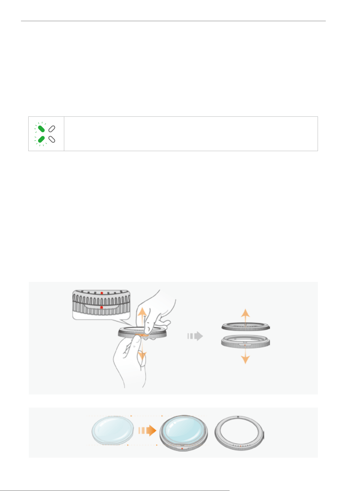
98
Antigravity A1 User Manual
©
2026 Antigravity All Rights Reserved
3. Why is the camera's stitching calibration not working properly?
It is recommended to carry out stitching calibration in a open outdoor environment. And, due to system limitations,
users will not be able to carry out the stitching calibration the following scenarios:
� Motors are rotating and the drone is in idle state.
� When it in the low light environment.
4. Are there any limitation when setting up waypoint in the Sky Path?
Yes. It is recommended only set up no more than 200 waypoints in a single ight route.
5. What if the lefthand side LED indicators keep blinking after power on?
It indicates battery error, contact your local resellers or ofcal customer service for help.
6. What should I do if my myopia prevent me from using he supplied corrective lenses?
Lens Selection Recommendations
1. The lens edge should not exceed 2.8mm. If the lens edge is between 2.5mm and 2.8mm, it is advisable to
remove the base of the lens frame to increase the thickness space when wearing Vision Goggles, to avoid the
lens being too close to the eye lashes.
2. It is recommended to use lenses with a refractive index of 1.60 or higher, which can make the lenses thinner
and lighter, and avoid the eyelashes touching the lenses.
3. It is recommended to use lenses with a prescription of up to +3.00 in conjunction with this frame to achieve the
optimal user experience.
4. The center of the customized lens must be identical to the center of the original lens. The pupillary distance on
the prescription is for reference, as it can be adjusted by the knob.
Installations of the Lens
1. Locate the red mark between two lens frames and separate them from each other.
2. Mount the new lens onto the base of the lens frame.
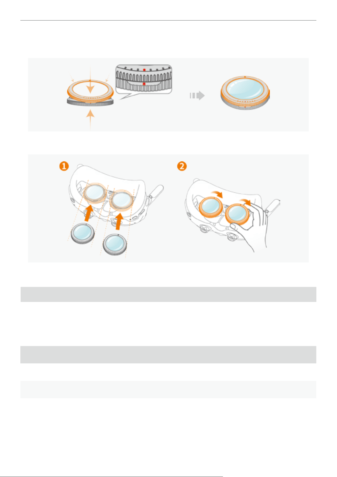
99
Antigravity A1 User Manual
©
2026 Antigravity All Rights Reserved
3. After mounting the lens on the base, adjust the position of the lens and apply pressure to ensure alignment
with the red dot on the base. Press down on the two components until you hear a “click”. Ensure there are no
gaps between two lens frames.
4. Attach the lens frame onto the Vision Goggles with the concave side facing you (the side with the lens frame
logo). For detailed installation instructions, please refer to “Using Vision Correction Lenses” on page 11.
Appendix
Compliance Information
MTOM Information
The aircraft’s Maximum Take-Off Mass (MTOM) is 249 g*, in compliance with the C0 classication requirements under
EU 2019/947 Regulation. When the drone is attached with the following approved accessories. The C0 certication
can be identied by the C0 label attached to the drone.
Name Model Size Weight
Antigravity A1 Propeller CINSBANG 15.85 × 74.7 3 × 5.88 mm 0.95 g
Antigravity A1 Flight Battery BDEmini-2360-7.16 50.8 × 27.2 × 89.6 mm 66.7 g
SD card N/A 11 × 15 × 1 mm 0.3 g
The aircraft’s Maximum Take-Off Mass (MTOM) is 291 g*, in compliance with the C1 classication requirements under
EU 2019/947 Regulation. When the drone is attached with the following approved accessories. The C1 certication
can be identied by the C1 label attached to the drone.

100
Antigravity A1 User Manual
©
2026 Antigravity All Rights Reserved
Name Model Size Weight
Antigravity A1 Propeller CINSBANG 15.85 × 74.7 3 × 5.88 mm 0.95 g
AntigravityA1 High Capacity
Flight Battery
BDEmax-4345-7.16 50.8 × 27.2 × 89.6 mm 108 g
SD card N/A 11 × 15 × 1 mm 0.3 g
Rotation Speed and Sound Level
Maximum Motor Rotation Speed 12,500 RPM
Sound Level 75 dB (A)
Maximum Vertical Speed at Landing 8 m/s (S mode)
Firmware Versions of RC Devices
Name Model Firmwares Version
Antigravity Vision Goggles DGS001 2.7
Antigravity Grip Motion Controller SRCSE001 2.7
Antigravity A1 Drone DE001 4.9
App Versions of RC Devices
Name Version Compatibility
Antigravity App 1.0.0 iOS 17.0 / Android 10.0 or later
Unity App 1.0.0 iOS 17.0 / Android 10.0 or later
List of Replacement Parts
Antigravity Propellers
Antigravity Flight Battery
Antigravity High-Capacity Flight Battery
Remote Identication Protocol
Transmission protocol: Bluetooth LE. Note that the Remote ID broadcasting is only required for the aircraft with C1
certication(MTOM above 250g) .
Disposal of Used Parts
Observe the local regulations related to electronic devices when disposing of the drone, goggles and remote
controller

101
Antigravity A1 User Manual
©
2026 Antigravity All Rights Reserved
Data Security and Privacy
Operator Registration
Upon the rst use of the Antigravity App, the app will prompt the user to sign up for registration. Once the registration
process is complete, the user can then proceed to access the full functionality of the A1 drone, including unlocking
restricted access to the airspace.
Data Integrity Risk for Drone Users
Attention Drone Users: Please be aware that the integrity of your data, including ight logs and media les, is at risk
of being compromised during upload and download operations. When transferring data between your drone and other
devices, there is a possibility of unauthorized access, data corruption, or loss. To safeguard your data, ensure that
secure transfer protocols are in place, and regularly back up important les to mitigate potential threats.
Maintenance Instructions
To avoid serious injury to children and animals, observe the following rule:
1. Store the Flight Battery and remote controller devices (i.e. Vision googles, Grip controller) in a cool, dry place away
from sunlight. Recommended storage temperature range is 22°-28°C (71°-82°F) for over three months. Do not store
outside 14°-113°F (-10°-45°C).
2. Keep the A1 drone dry. If the A1 drone comes into contact of water or liquid, dry with a soft cloth. Never use alcohol,
benzene, or ammable substances to clean it. Avoid humid or dusty storage areas.
3. Only connect to USB version 3.0 or newer. Do not use “power USB” devices.
4. Inspect all parts after any crash. Contact an authorized dealer if needed.
5. Regularly check Battery Level Indicators of the Flight Battery. The design charging cycle for the battery is 300
cycles; do not use the battery beyond this limit.
6. Transport the A1 drone with all arms folded when powered off.
7. Fold all antennas of the Vision goggles during transportation.
8. Charge the battery to exit sleep mode after long-term storage.
9. Store all devices (including but limited to A1 drones, Vision googles and Grip controllers) in a dry environment.
There is no altitude requirement for storage.
10. Remove the battery before servicing the A1 drone. Clean with a soft, dry cloth and avoid alcohol-based cleaners.
11. Turn off the battery before replacing or checking propellers.
FPV Operator Warning
While the operator is controlling the aircraft in FPV mode, it is essential to have a visual observer situated near the
operator. The visual observer should be able to assist the operator in conducting the ight safely. Additionally, the
visual observer must be able to communicate clearly with the operator.
GEO Awareness
Prerequisite:
Download the latest UGZ le from the EASA website (www.easa.europa.eu) and transfer the UGZ le to your mobile
device.
Uploading UGZ:
Follow the instructions below to set up and refresh the UGZ database on the app.
1. Power on the drone, remote controller and the goggles. Ensure all devices are connected to each other.
2. Launch the app.
3. Go to “Settings > UGZ File Management”, tap “ Import” to start importing the UGZ le. Follow the on-screen
instructions to complete the process.
4. When importing of the UGZ is complete successfully, you may see the prompt successful message on both the app
and the goggle UI.

102
Antigravity A1 User Manual
©
2026 Antigravity All Rights Reserved
When UGZ Enabled:
Upon the aircraft approaching the restricted areas (horizontal distance: 160 meters, vertical distance: 40 meters) that
are dened in the UGZ le, a warning message will prompt on the goggles to alert that user that the aircraft is about to
entering the restricted area.
Remote ID
Follow the instructions below to upload the Remote ID of the aircraft operator.
1. Power on the goggles and then launch the app. Ensure the goggles is connected to the Antigravity app.
2. Access to the “Setting” from the main menu of the app, then proceed to click on the “Binding Operator Remote ID”.
Refer to the in-app prompts
3. Follow the on-screen instruction to complete the Remote ID registration. Upon the completion of Remote ID
registration, the user’s ID will appear in the “Account Safety” section.
4. When powered on, the drone automatically performs a Remote ID self-test. Before take off, please ensure the
message of “Remote ID self-check passed” is displayed.
General Warning Messages
GNSS
If the Global Navigation Satellite System (GNSS) signal deteriorates, the following warning message will pop up in the
Vision Goggles.
� Navigation system anomaly, please return to home point immediately.
� Alert: Remote ID GNSS System Failure Broadcasting disabled due to self-test anomaly. Conrm local ight
permissions and contact customer support immediately for resolution.
Flight Battery
In the event of the Flight Battery performance is affected, the following warning message will be prompted in the Vision
Goggles.
� The remaining power is only enough to return to the return point, and will automatically return. Click [C2 button] to
cancel.
Loss Control Signal
In the event of loss of the control signal between the controller and the drone, the following warning message will be
prompted in the Vision Goggles.
� Transmission signal lost. The drone will hover Select RTH: Transmission signal lost. The drone will return.
� Remote control signal lost. The drone will hover Select RTH Remote control signal lost. The drone will return.
Geo Sensing
Upon approaching the designated restricted ight area, the following warning message will be prompted in the Vision
Goggle.
� The aircraft is about to touch the no y zone and its ight direction is restricted. Please control the plane to stay away
or land safely as soon as possible.
� The aircraft has entered the no-y zone. Please leave as soon as possible.
� The aircraft has reached the current height limit.