OPERATOR MANUAL
IMPORTANT INFORMATION, KEEP FOR OPERATOR
REV. D (05/25)
This manual provides information for:
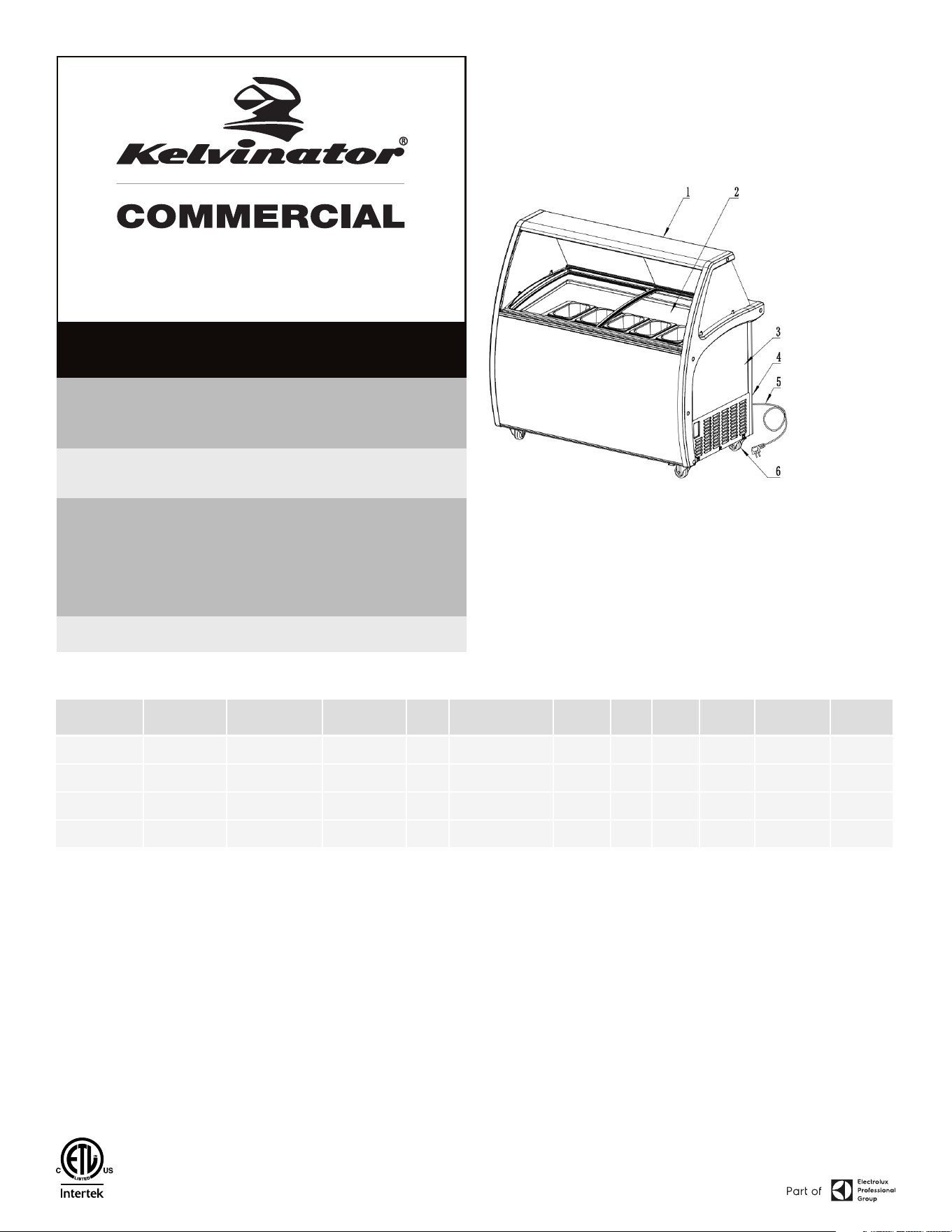
DIPPING CABINET
THIS MANUAL MUST BE RETAINED FOR FUTURE REFERENCE. READ,
UNDERSTAND AND FOLLOW THE INSTRUCTIONS AND WARNINGS
CONTAINED IN THIS MANUAL.
FOR YOUR SAFETY Do not store or use gasoline or other ammable
vapors and liquids in the vicinity of this or any other appliance.
NOTIFY CARRIER OF DAMAGE AT ONCE It is the responsibility of the
consignee to inspect the container upon receipt of same and to determine
the possibility of any damage, including concealed damage. Electrolux
Professional suggests that if you are suspicious of damage to make a
notation on the delivery receipt. It will be the responsibility of the consignee
to le a claim with the carrier. We recommend that you do so at once.
Manufacture Service/Questions 866-339-8515.
USA & Canada, 866-339-8515
4003 Collins Lane, Louisville, KY 40245
www.kelvinatorcommercial.com
Kelvinator Commercial is a pending or registered trademark of Electrolux Consumer Products, Inc., and is used under a license from Electrolux Consumer Products, Inc. Information
contained in this document is known to be current and accurate at the time of printing/creation. Reference our product line website for the most updated product information and
specications. © 2025 Electrolux Professional, Inc. All Rights Reserved.
EQUIPMENT DESCRIPTION
MODEL NO. REFRIGERANT
TYPE
REFRIGERANT
WEIGHT, G
V/HZ/PH AMPS CAPACITY
STORAGE (CU FT)
TUB 3
GAL SIZE
HP BTU CHARGE
OZ
SHIP WEIGHT
LBS
NEMA
PLUG
KCICDC4FH R290 68 115/60/1 1.3 6.0 4 1/5 1000 2.4 238 5-15P
KCICDC6FH R290 95 115/60/1 1.4 8.5 6 1/5 1350 3.35 304 5-15P
KCICDC8FH R290 110 115/60/1 2 10.9 8 1/4 1700 3.88 357 5-15P
KCICDC10FH R290 130 115/60/1 4.1 13.9 10 1/2 2230 4.59 439 5-15P
RETAIN THIS MANUAL FOR FUTURE REFERENCE
NOTICE: Due to a continuous program of product improvement, Electrolux
Professional reserves the right to make changes in design and specications
without prior notice.
NOTICE: Please read the entire manual carefully before installation. If certain
recommended procedures are not followed, warranty claims will be denied.
RECEIVING & INSPECTING THE EQUIPMENT
Even though most equipment is shipped crated, care should be taken during
unloading so the equipment is not damaged while being moved into the
building.
1. Visually inspect the exterior of the package and skid or container. Any
damage should be noted and reported to the delivering carrier immediately.
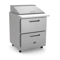
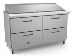
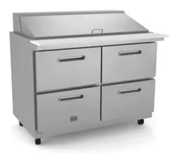
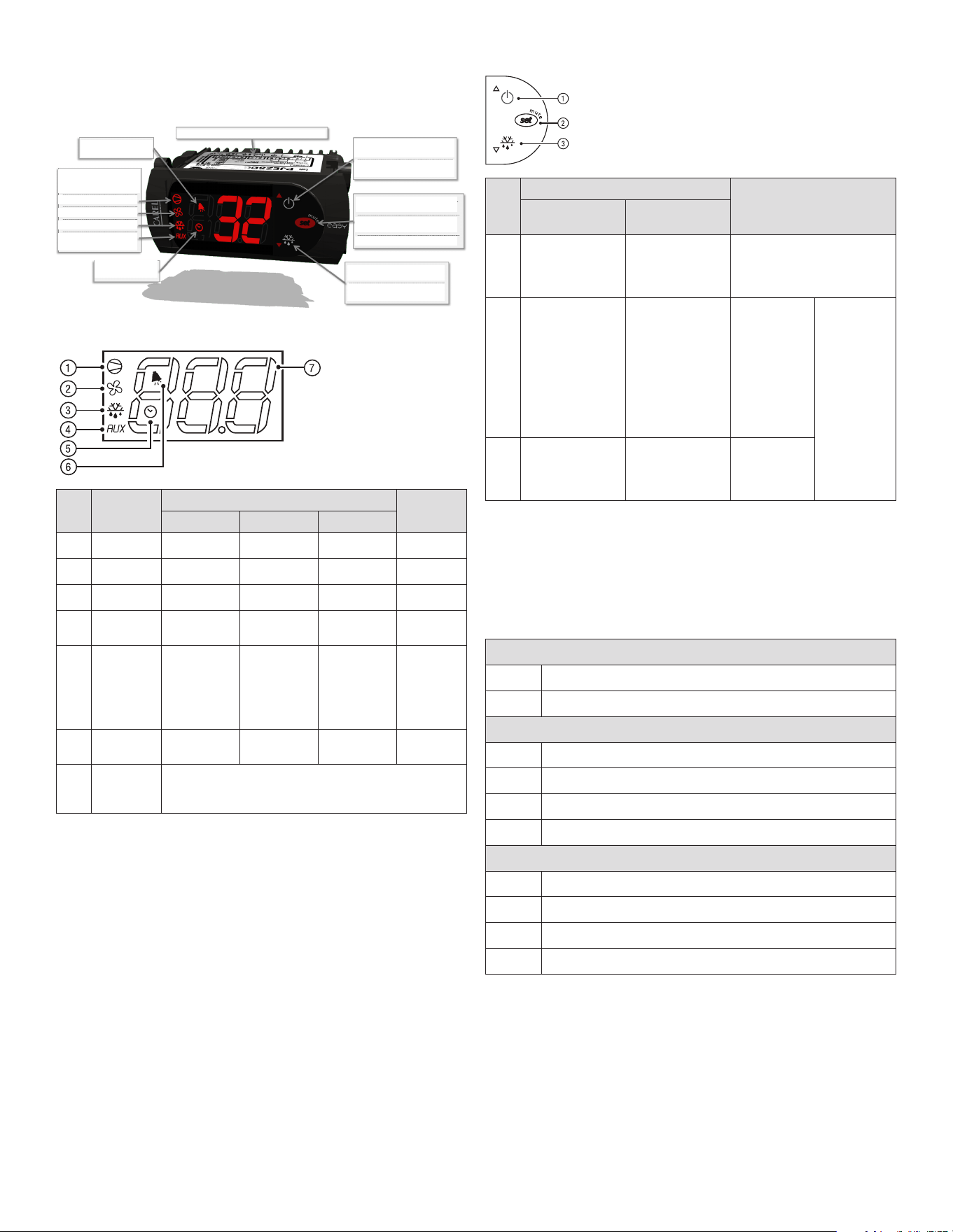
1. Canopy
2. Glass lid
3. Cabinet
4. Control panel
5. Power cord
6. Castor
2. If damaged, open and inspect the contents with the carrier.
3. In the event that the exterior is not damaged, yet upon opening, there is
concealed damage to the equipment, notify the carrier. Notication should be
made verbally as well as in written form.
4. Request an inspection by the shipping company of the damaged equipment.
This should be done within 10 days from receipt of the equipment.
5. Be certain to check the compressor compartment housing and visually
inspect the refrigeration package. Be sure lines are secure and base is still
intact.
6. Freight carriers can supply the necessary damage forms upon request.
7. Retain all crating material until an inspection has been made or waived.

2 OM-DIPPING CABINET
INSTALLATION
1. When you transport the showcase, the angle between the compartment
body and the ground should be no more than 45°and you should never
place the showcase up-side down.
2. Do not use any of the external part as loading points, for example, the
condenser on the back, the door.
3. When the showcase is installed or used, all the package (including board
and foam plastic) should be got rid of.
4. Keeping the showcase stable to avoid vibration and noise.
5. The showcase should be installed in the
place with good ventilation, a space of at
least 10cm should be allowed between the
surrounding walls and the cabinet wall for
air condition.
6. It should be placed far from heating
resource and not under direct sunshine
to avoid decrease of the efciency of
refrigeration.
7. Install the showcase in a dry place so as
to prevent rust on the compartment body,
which may affect the electric insulation.
IMPORTANT - READ FIRST - IMPORTANT
YOUR SAFETY AND THE SAFETY OF OTHERS ARE VERY IMPORTANT.
WE HAVE PROVIDED MANY IMPORTANT SAFETY MESSAGES IN THIS MANUAL AND ON YOUR
APPLIANCE. ALWAYS READ AND OBEY ALL SAFETY MESSAGES.
THESE ARE THE SAFETY ALERT SYMBOLS. THESE SYMBOL ALERT YOU TO
POTENTIAL HAZARDS THAT CAN KILL OR INJURE YOU AND OTHERS. ALL SAFETY
MESSAGES WILL FOLLOW THE SAFETY ALERT SYMBOLS AND EITHER THE
WORDS “DANGER”, “WARNING” OR “CAUTION”.
DANGER MEANS THAT FAILURE TO HEED THIS SAFETY STATEMENT MAY RESULT
IN SEVERE PERSONAL INJURY OR DEATH.
WARNING MEANS THAT FAILURE TO HEED THIS SAFETY STATEMENT MAY
RESULT IN EXTENSIVE PRODUCT DAMAGE, SERIOUS PERSONAL INJURY, OR
DEATH.
CAUTION MEANS THAT FAILURE TO HEED THIS SAFETY STATEMENT MAY RESULT
IN MINOR OR MODERATE PERSONAL INJURY, OR PROPERTY OR EQUIPMENT
DAMAGE.
ALL SAFETY MESSAGES WILL ALERT YOU TO WHAT THE POTENTIAL HAZARD IS, TELL YOU
HOW TO REDUCE THE CHANCE OF INJURY, AND LET YOU KNOW WHAT CAN HAPPEN IF THE
INSTRUCTIONS ARE NOT FOLLOWED.
BEFORE THE CHEST SHOWCASE IS USED, IT MUST BE PROPERLY POSITIONED AND INSTALLED
AS DESCRIBED IN THIS MANUAL, SO READ THE MANUAL CAREFULLY. TO REDUCE THE RISK OF
FIRE, ELECTRICAL SHOCK OR INJURY WHEN USING THE CHEST SHOWCASE, FOLLOW BASIC
PRECAUTIONS, INCLUDING THE FOLLOWING:
DANGER: THIS APPLIANCE IS NOT INTENDED FOR USE BY PERSONS (INCLUDING
CHILDREN) WITH REDUCED PHYSICAL, SENSORY OR MENTAL CAPABILITIES,
OR LACK OF EXPERIENCE AND KNOWLEDGE, UNLESS THEY HAVE BEEN GIVEN
SUPERVISION OR INSTRUCTION CONCERNING USE OF THE APPLIANCE BY A
PERSON RESPONSIBLE FOR THEIR SAFETY
DANGER: CHILDREN SHOULD BE SUPERVISED TO ENSURE THAT THEY DO NOT PLAY WITH
THE APPLIANCE.
DANGER: RISK OF CHILD ENTRAPMENT: CHILD ENTRAPMENT AND SUFFOCATION ARE
NOT PROBLEMS OF THE PAST. JUNKED OR ABANDONED SHOWCASES ARE STILL
DANGEROUS, EVEN IF THEY WILL “JUST SIT IN THE GARAGE A FEW DAYS.”
DANGER: BEFORE YOU THROW AWAY YOUR OLD SHOWCASE: TAKE OFF THE DOORS. LEAVE
THE SHELVES IN PLACE SO THAT CHILDREN MAY NOT EASILY CLIMB INSIDE.
DANGER: PLEASE ACCORDING TO LOCAL REGULATION DISPOSAL OF THE APPLIANCE FOR
ITS FLAMMABLE REFRIGERANT AND BLOWING GAS.
DANGER: THE SHOWCASE MUST USE THE SEPARATE PIN OUTLET TO BE CONNECTED WITH
EARTH CORRECTLY, NEVER WITH THE HEATING PIPE AND COAL GAS PIPE.
DANGER: THE SHOWCASE SHALL BE POSITIONED SO THAT THE PLUG IS ACCESSIBLE.
DANGER: IF THE SUPPLY CORD IS DAMAGED, THE MANUFACTURER OF ITS SERVICE AGENT
OR A SIMILARLY QUALIFIED PERSON MUST REPLACE IT IN ORDER TO AVOID A
HAZARD.
DANGER: DO NOT ATTEMPT TO REPAIR OR REPLACE ANY PART OF YOUR CHEST
SHOWCASE UNLESS IT IS SPECIFICALLY RECOMMENDED IN THIS MATERIAL. ALL
OTHER SERVICING SHOULD BE REFERRED TO A QUALIFIED TECHNICIAN.
WARNING: THE CHEST SHOWCASE SHOULD NOT BE LOCATED NEXT TO OVENS, GRILLS OR
OTHER SOURCES OF HIGH HEAT.
WARNING: KEEP VENTILATION OPENINGS, IN THE APPLIANCE ENCLOSURE OR IN THE BUILT-
IN STRUCTURE, CLEAR OF OBSTRUCTION.
WARNING: DO NOT USE MECHANICAL DEVICES OR OTHER MEANS TO ACCELERATE
THE DEFROSTING PROCESS, OTHER THAN THOSE RECOMMENDED BY THE
MANUFACTURER.
WARNING: DO NOT DAMAGE THE REFRIGERANT CIRCUIT.
WARNING: DO NOT USE ELECTRICAL APPLIANCES INSIDE THE FOOD STORAGE COMPARTMENTS
OF THE APPLIANCE, UNLESS THEY ARE OF THE TYPE RECOMMENDED BY THE
MANUFACTURER.
WARNING: BEFORE PROCEEDING WITH CLEANING AND MAINTENANCE OPERATIONS, MAKE
SURE THE POWER LINE OF THE UNIT IS DISCONNECTED.
WARNING: DO NOT CONNECT OR DISCONNECT THE ELECTRIC PLUG WHEN YOUR HANDS ARE
WET.
WARNING: DO NOT STORE OR USE GASOLINE OR ANY OTHER FLAMMABLE VAPORS AND
LIQUIDS IN THE VICINITY OF THIS OR ANY OTHER SHOWCASE. NEVER CLEAN
SHOWCASE PARTS WITH FLAMMABLE FLUIDS. THE FUMES CAN CREATE A FIRE
HAZARD OR EXPLOSION.
WARNING: IF THE VOLTAGE IS UNSTABLE, PLEASE CHOOSE THE SUITABLE AUTOMATIC VOLTAGE
REGULATOR.
WARNING: CONNECTION THE POWER TO CHECK THE SHOWCASE BEFORE USING, THE
SHOWCASE CAN BE USED UNTIL THE TEMPERATURE DECREASES OBVIOUSLY AFTER
30 MINUTES.
WARNING: YOU SHOULD ADJUST THE TEMPERATURE CONTROL ACCORDING TO THE REQUESTED
TEMPERATURE AND QUANTITY OF THE STORED FOOD AND THE ENVIRONMENTAL
TEMPERATURE.
WARNING: BEFORE PUTTING THE STUFF INTO THE SHOWCASE PLEASE ADJUST THE
TEMPERATURE CONTROL TO THE LOWEST POINT AND LET IT WORK TILL THE
TEMPERATURE OF INNER CABINET DECREASES TO -18℃ AND THEN PUTTING THE
STUFF IN, AFTER 12 HOURS ADJUST THE TEMPERATURE CONTROL TO THE NORMAL
POINT.
WARNING: NEVER PUT HOT FOOD IN THE SHOWCASE DIRECTLY ONLY AFTER IT HAS BEEN
COOLED NATURALLY OUTSIDE.
WARNING: THE STUFF SHOULD BE PUT INTO THE SHOWCASE PARTIALLY, EACH LOT WILL NOT
BE MORE THAN THE FIGURE WHICH IS EQUAL TO THE CAPACITY(L) DIVIDE BY 20.
WARNING: NOT FULL THE SHOWCASE AND MAKE IT CROWDED, BIG MEAT SHOULD BE DIVIDED
INTO SEVERAL SMALL PARTS. THERE SHOULD BE REASONABLE SPACE BETWEEN
THE FOODS FOR BETTER FREEZING.
WARNING: IF POWER CUT OFF IS NEEDED, YOU SHOULD WAIT FOR AT LEAST 5 MINUTES
BEFORE TURN ON AGAIN TO AVOID DAMAGE TO THE COMPRESSOR.
WARNING: THE STUFF STORED SHOULD BE PACKED WITH PLASTIC BAG WELL TO AVOID
SMELL-MIXED AND MOISTURE-LOST, AND REDUCE THE FROST AT THE SMALL TIME
WARNING: BEER, BEVERAGE, FRESH FLOWER, MEDICINE AND INJECTIONS CAN NOT BE PUT
INTO THE SHOWCASE.
WARNING: PLEASE MAKE THE TEMPERATURE CONTROL TO THE LOWEST POINT IF YOU WANT
TO STORE ICE CREAM OR OTHER UNEASY-FROZEN FOOD.
WARNING: WE HAVE A POLICY OF CONTINUOUS IMPROVEMENT ON OUR PRODUCTS AND
RESERVE THE RIGHT TO CHANGE MATERIALS AND SPECIFICATIONS WITHOUT
NOTICE. TO CONFIRM THE SPECIFIC PARAMETERS, PLEASE ACCORD TO THE RATED
LABEL ON THE PRODUCT.
WARNING: SHALL, WHEN THE PRODUCT SCRAP/RECOVERED BY PROFESSIONAL SCRAP/
RECYCLING LOCATIONS TO DEAL WITH.
WARNING: THIS PRODUCT APPLICATION ENVIRONMENT TEMPERATURE UP TO 43ºC℃.

3 OM-DIPPING CABINET
OPERATION
CONTROL PANEL
Electronic Thermostat
CAREL SERIES REFRIGERATION CONTROL – FIELD SUPPORT GUIDE
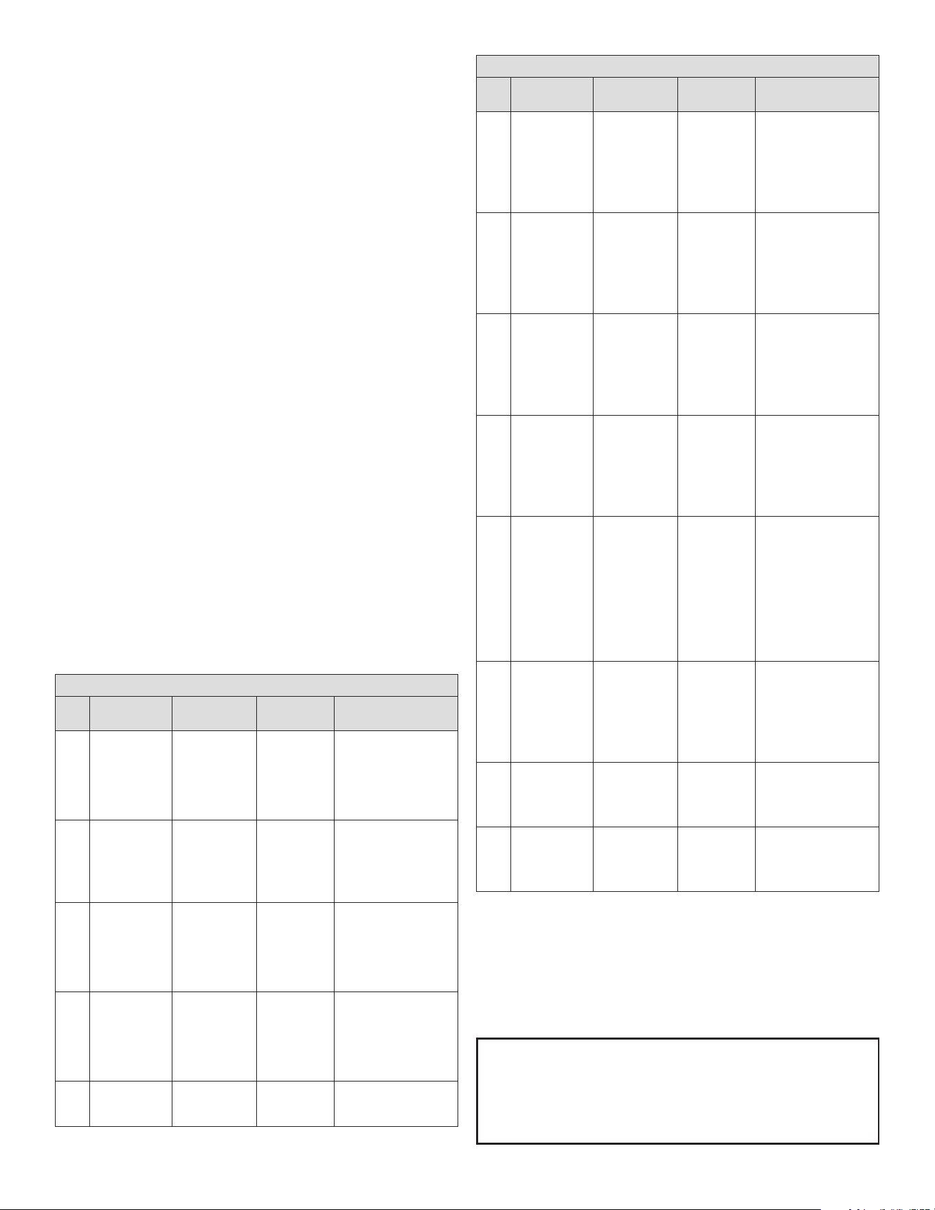
1. Overview of the Easy control’s display and buttons:
2. Wiring the control’s connections correctly:
Carel controls come in a wide variety of different configurations, often
customized for the OEM appliance manufacturer. A label found on top of the control will show a wiring guide and electrical
specifications for the specific model. When replacing the control, DO NOT ASSUME that the numbered terminals will always serve
the same function as the previous control installed. Carefully check all connections according to the labels / symbols shown
underneath each numbered contact.
Common Configurations: PJEZS* Models – Medium Temp PJEZC* Models – Low Temp
Carefully note the following connections available on your model, and connect the wires accordingly.
Temperature probe input(s)
Control probe (AMB) and optional defrost probe (DEF), with a common
Digital input
Configurable input for alarm, defrost, curtain etc. (Parameter A4)
Compressor output
Contact points may vary across different control models
Fan output
Contact points may vary across different control models
Defrost output
Contact points may vary across different control models
Auxiliary output
Contact points may vary across different control models
Line voltage to outputs
L
Typically isolated from supply voltage, requiring its own connection
Supply voltage
L/N
Line and neutral supply wires, most commonly points 6 and 7
3. Viewing and changing the set point:
Press and hold the red SET button for 1 second to view current set point,
and release immediately after it is displayed. (Display may flash, indicating the value can be changed.)
Press UP and DOWN arrows to change value and press SET again to store new value.
DISPLAY
BUT.
NO.
FUNCTION
NORMAL OPERATION
START UP
ON OFF FLASH
1 Compressor On Off Call On
2 Fan On Off Call On
3 Defrost On Off Call On
4
Auxiliary
Output (AUX)
Output Active
Output Not
Active
-
On
5 Clock (RTC)
RTC available,
enabled
(tEN=1) and
at least one
time band has
been set
RTC not
available or not
enabled
(tEN=0) or no
time band set
RTC available,
enabled
(tEN=1) and
at least one
time band has
been set
ON (if the
clock is
tted)
6 Alarm
Alarm In
Progress
No Alarm In
Progress
-
On
7 Digits
Three digits with decimal point and range -199 to 999. See
parameters /4, /5, /6 for the type of probe displayed, values in °C/°F
and decimal point
KEYPAD (MODELS C, S, X, Y)
BUT.
NO.
NORMAL OPERATION
START UP
PRESSING THE
BUTTON ALONE
PRESSING WITH
OTHER BUTTONS
1
More than 3 s:
Switch ON/OFF
Pressed together
with 3 activates /
deactivates the
continuous cycle
-
2
- 1 s: displays/sets
the set point
- More than 3 s:
accesses the
parameter setting
menu (enter
password 22)
- Mutes the audible
alarm (buzzer)
-
For 1 s RESET
current EZY
set
Pressed
together (2
and 3) activate
parameter
reset procedure
3
More than 3 s:
activates /
deactivates the
defrost
Pressed together
with 1 activates /
deactivates the
continuous cycle
For 1 s displays
rmware
version
PRELIMINARY CONFIGURATIONS
Once the electrical connections have been completed, simply power-up the
controller to make it operative. It is recommended to check that the display does
not show any alarm signals (see “Table of alarms and signals”) and then set the
parameters as desired. The main parameters are as follows (See functions and
parameters section for more detail.):
CONTROL PARAMETERS
St Set point
rd Set point differential
DEFROST PARAMETERS
d0
Type of defrost
dl
Interval between two defrosts
dt
End defrost temperature
dp
Maximum defrost duration
ALARM PARAMETERS
Ad
Temperature alarm delay
AL
Low temperature alarm threshold/deviation
AH
High temperature alarm threshold/deviation
A0
Alarm and fan temperature differential
FUNCTIONS AVAILABLE FROM THE KEYPAD:
On and off:
Switching the instrument ON: press UP for more than 3 s (when pressing the
button, the display shows ON).
Switching the instrument OFF: press UP for more than 3 s. The display shows
the message “OFF”, alternating with the temperature measured by the set probe.
In off status, the following functions are disabled (if featured by the model):
• compressor control / duty setting / continuous cycle
• defrost
• fan control
4 OM-DIPPING CABINET
• alarms : ‘LO’, ‘HI’, ‘IA’, ‘cht’, ‘CHT’
• door switch: A4=7/8
• buzzer (when available)
While the following are enabled:
• temperature display, alternating with the message “OFF”
• parameter display and setting
• alarms: “E0”, “E1”, “E2”
• the internal timer relating to parameter ‘dI’ is updated. If ‘dI’ expires in OFF
status, a defrost is performed when restarting
• auxiliary relay management, only in the following congurations:
– H1= = 1/2 (“E0” alarm only)
– H1= 3, A4= 6
Note: when exiting OFF status, the following settings are set to zero (that is, are
not saved prior to OFF): evaporator fan alarm hysteresis and management (A0),
temperature control hysteresis (rd), cht pre-alarm hysteresis (AE). In addition,
the delays are set to zero for the display of the temperature alarms (Ad, d8, c6),
dripping (dd) and post dripping (Fd).
WARNINGS:
• when rst connected, controller is already on and ready to be used
• the instrument can be switched on from a supervisor PC and via an external
contact (setting A4= 5). The latter has priority over the other modes.
Set point setting (desired temperature value):
The controller device control the desired temperature (set point) inside the
cabinet or cold room directly and dynamically.
To view and modify the set point:
• press SET for 1 s, the set value will start ashing (indicating the value can be
changed)
• increase or decrease the value using UP or DOWN
• press SET to conrm the new value
• press and hold SET for up to 5 s to save any changes made, display will
return to temperature reading
Note: If nal step is not performed correctly, all of your parameter changes may
be lost
Manual Defrost:
- Not available on the easy thermometer (M) and easy compact models.-
Press DOWN for more than 3 s (activated only if the temperature conditions are
right, for easy split only if the light output is not set, H1≠4).
Continuous Cycle:
- Not available on the easy thermometer (M) and easy compact models.-
Press UP+DOWN for more than 3 s (activated only if the temperature conditions
are right and for easy split only when H6=0). The continuous cycle is used
to maintain refrigeration active in the cabinet or cold room, regardless of
the temperature inside the unit. This may be useful for rapidly bringing the
temperature below the set point value.
FUNCTIONS AND PARAMETERS
COMMON CONTROL PARAMETERS / DEFINITIONS
PAR. DESCRIPTION
PS Password
/2 Probe measurement stability
/4
Select probe displayed by default [ 1=Amb; 2=Def; 3=Dig.IN]
/5
Select °C/°F temperatures displayed [0=°C; 1=°F] (see note below)
/6
Disable decimal point [0=temp displayed to tenth of degree; 1= temp
displayed WITHOUT tenths of a degree]
/C1
Probe 1 offset / calibration (+ or - temp value)
/C2
Probe 2 offset / calibration (+ or - temp value)
St
Set point
rd
Control differential (St + rd = Comp Cut-IN)
r1
MINIMUM allowable set point value
r2 MAXIMUM allowable set point value
DEFROST PARAMETERS / DEFINITIONS
PAR. DESCRIPTION
d0
Type of defrost [0=elec. by TEMP; 1=hot gas by TEMP; 2=elec. by TIME; 4=
TEMP w/ TIME]
dl Hours between automatic defrost starts (defrost intervals)
dt
End defrost temperature set point / defrost temperature threshold with
temp. control (ignored if d0=2 or 3)
dp
Maximum defrost duration (in minutes) (MAX timeout if d0=4)
ALARM PARAMETERS / DEFINITIONS
PAR. DESCRIPTION
A0 Alarm and fan temperature differential [0=AL & AH are absolute values]
AL LOW temperature alarm value
AH
HIGH temperature alarm value
Ad
Temperature alarm delay
A4
Conguration of digital input [0=disabled; 1=external alarm; 2=enable
defrost; 4=curtain/night mode; 5=remote ON/OFF; 6=AUX out; 9=direct/
reverse mode]
A7
Digital input alarm delay
A8
Enable alarm “Ed” (end defrost by timeout)
AC
Set point dirty condenser alarm
AE
Dirty condenser alarm differential temperature
Acd
Dirty condenser alarm delay
OTHER PARAMETERS / DEFINITIONS
PAR. DESCRIPTION
H0 Serial address
H1
AUX output conguration [0=disabled; 1=alarm N.C.; 2=alarm N.O.; 3= dig.
Input]
H2
Enable keypad [0=enabled] or [1=disabled]
H4
Disable alarm buzzer [0=enabled] or [1=disabled]
Any parameter codes not found may have been removed by the OEM during
customization. Skip them for now, and should any operational problems remain,
consult the OEM appliance manufacturer for advice.
Note: when changing temperature mode between CELCIUS and FAHRENHEIT
(parameter /5), be sure to check / reset the highlighted common parameters in
addition to the set point. Stored temperature values do not convert automatically
after changing the “/5” setting.
5 OM-DIPPING CABINET
CONTINUOUS CYCLE
The continuous cycle is used to maintain refrigeration continuously active,
regardless of the temperature inside the unit. The function is used to rapidly
lower the product temperature, even below the set point, for example after lling
the cabinets. In this phase, the temperature may fall below the set point.
To activate or deactivate the continuous cycle from the keypad, see keypad
functions section.
the display shows “cc” and the icon ashes (2 ashes, pause).
cc: continuous cycle duration
This represents the time in hours that the compressor operates continuously for
so as to lower the temperature, even below the setpoint. If cc=0 the continuous
cycle is not activated. The controller exits the continuous cycle procedure after
the time set for parameter “cc” has expired, or when reaching the minimum
temperature (see the minimum temperature alarm, parameter AL).
c6: temperature alarm bypass after continuous cycle
This is the time in hours during which all the temperature alarms are deactivated
after a continuous cycle. If the temperature of the refrigerated unit, after the
continuous cycle, lowers due to inertia below the minimum temperature
threshold (set point-AL), the activation of the low temperature alarm is
delayed for the time c6. In any case, the continuous cycle is deactivated at the
temperature (set point-AL).
ALARMS AND SIGNALS
When an alarm is activated, the display shows the corresponding message that
ashes alternating with the temperature; if tted and enabled, the buzzer and the
alarm relay are also activated.
All the alarms have automatic reset (that is, they stop when the causes are no
longer present), except for alarm ‘CHt’ which has manual reset (instrument on/
off using the UP button or by disconnecting the power supply). Pressing the SET
button mutes the buzzer, while the code displayed and the alarm relay only go off
when the causes of the alarm have been resolved. The alarm codes are shown in
the table below:
TABLE OF ALARMS AND SIGNALS
PAR.
BUZZER AND
ALARM RELAY
DESCRIPTION RESET CAUSE/ NOTE
E0 Active
Probe 1 error =
control probe
Automatic
Probe not working:
the probe signal is
interrupted or short-
circuited; or probe
not compatible with
instrument
E1 Not active
Probe 2 error =
defrost/evaporator
probe
Automatic
Probe not working:
the probe signal is
interrupted or short-
circuited; or probe
not compatible with
instrument
E2
Not active
Probe 3 error =
condenser/product
probe
Automatic
Probe not working:
the probe signal is
interrupted or short-
circuited; or probe
not compatible with
instrument
IA Active
External alarm Automatic
Immediate or delayed
alarm from multifunction
digital input.
• Check the
multifunction input and
parameters A4 and A7
dOr Active
Open door alarm Automatic
Check the multifunction
input and parameters A4
and A7
TABLE OF ALARMS AND SIGNALS
PAR.
BUZZER AND
ALARM RELAY
DESCRIPTION RESET CAUSE/ NOTE
LO Active
Low temperature
alarm - cooling
below set point
Automatic
The probe has
measured a temperature
lower than the set point
by a value that exceeds
parameter AL.
• Check parameters AL,
Ad and A0.
HI
Active
High temperature
alarm
Automatic
The probe has
measured a temperature
higher than the set point
by a value that exceeds
parameter AH.
• Check parameters AH,
Ad and A0
EE Not active Unit parameter error
Not
possible
Unit parameter reading
error.
If the fault persists, the
controller needs to be
replaced. If the message
disappears, it can
continue to be used
EF Not active
Operating
parameter error
Manual
Operating parameter
reading error.
If the fault persists, the
controller needs to be
replaced. If the message
disappears, it can
continue to be used
Ed Not active
Defrost ended by
timeout
On rst
defrost
ended
correctly
The last defrost ended
after exceeding the
maximum duration
rather than when
reaching the end defrost
set point.
• Check parameters dt,
dP and d4
• Check the efciency
of the defrost
dF Not active
Defrost running Automatic
Defrost running:
• This is not an alarm
signal, but rather a
message that the
instrument is running
a defrost. Only shown
if d6= 0.
cht Not active
Dirty condenser
pre-alarm
Automatic
Dirty condenser pre-
alarm:
• Check parameters A4,
Ac, AE and Acd.
CHt
Active
Dirty condenser
alarm
Manual
Dirty condenser alarm:
• Check parameters A4,
Ac, AE and Acd.
STORAGE
1. The appliance is suitable for storing ice cream and ready-frozen foods.
2. It must not be lled higher than the stacking mark on the inside of the
showcase.
3. If there is no load line sticker, please take the top of placed basket as standard.
LOAD LINE
6 OM-DIPPING CABINET
DEFROST
1. Defrost when the frost thickness on the wall of the cabinet reaches 5mm to
optimize the freezing capacity.
2. Turn the temperature control to the lowest point for 5-6 hours before defrosting.
3. Cut off the power and take out the food, use the defrost removal, do not apply
sharp tools.
4. After defrosting, clean the wall with dry cloth, and then power on.
The following phenomena are normal
1. There will be sound of owing water when the refrigerant is running.
2. The frozen food do not melt even if a long time power off.
3. When the environment humidity is too high, there will be dew condensed on the
surface of the showcase.
4. When the machine is running, the condenser and compressor will be hot.
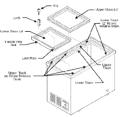
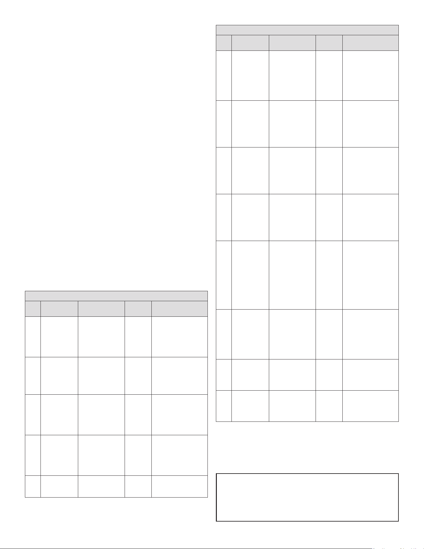
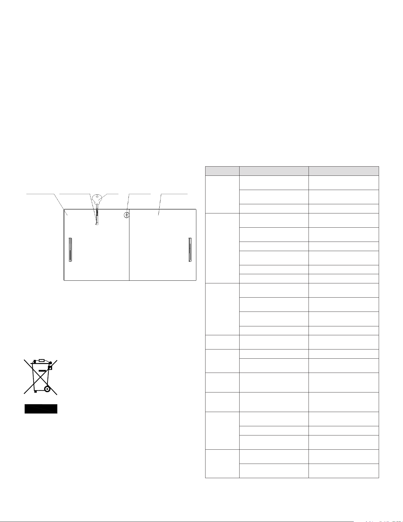
LOCK
1. You can lock the freezer: First step you put the key and key cylinder into lock
hole; The second step you turn the key rotate 90° CW; Then you put out the key.
2. You can unlock the freezer: First step you turn the key rotate 90° CCW; The
second step you put out the key and key cylinder from lock hole.
NOTES: The lock is one of the options your product may not have.
MAINTENANCE
1. Do not open the door frequently or for too long
to save energy.
2. Never leave heavy or hot stuff on the top of the
showcase to avoid deforming.
3. Cut off the power before cleaning.
4. To clean the showcase, please use soft cloth dampened in some moderate
detergent and hot water.
5. Use warm water to clean oil or fruit juice stain on the magnetic gasket in
order to keep its elasticity. Apply some talcum powder to it to prolong its
service life.
6. The showcase should not be left unused for a long time, to stop using the
showcase, disconnect the main power rst, then clean the inside and leave
the door open for 2-3 days to dry it.
CORRECT DISPOSAL OF THIS PRODUCT
This marking indicates that this product should not be disposed with other
household wastes. To prevent possible harm to the environment or human
health from uncontrolled waste disposal, recycle it responsibly to promote the
sustainable reuse of material resources. To return your used device, please use
the return and collection systems or contact the retailer where the product was
purchased. They can take this product for environmental safe recycling.
REPLACEMENT PARTS
To order parts, contact your Authorized Service Agent. Supply the model
designation, serial number, part description, part number, quantity, and when
applicable, voltage and phase.
CONTACT US
In order to obtain service the unit must rst be registered at Kelvinator
Commercial.com. Once registered please call 866-339-8515 for assistance.
TROUBLESHOOTING
PROBLEM CAUSE SOLUTION
Unfreezing
Temperature control is on the
highest temperature point (1 point)
Adjust temperature control
Plug and outlet not connected well Make both of them connect well
Fuse broken off Change the fuse
Compressor
can not stop
working
Temperature control is on the
lowest temperature point (7 point)
Adjust temperature control
Too much stuff stored in one time Reduce the quantity
Thick frost Defrost
Too many times of door-opening Reduce the times of door-opening
Too near the wall Far from the wall
Near the hot source or sun Change the place
Too warm
Temperature control is on the
highest temperature point (1 point)
Adjust temperature control
Too much stuff stored in one time Reduce the quantity
Too many times of door-opening Reduce the times of door-opening
Near the hot source or sun Change the place
Too cold
Temperature control is on the
lowest temperature point (7 point)
Adjust temperature control
Big noise or
violent vibration
Ground is not at Change the place
Refrigerating tubes connected Separate them
Water on the
oor
The condensation water on the
lids drops down from the drain
pipe to the oor
Pour out the water from the water
collector
Water
condensation
on the lids
The environment humidity is too
high
Dry the lids with a soft cloth
Excessive ice
formation in
cabinet
Too many times of door-opening Reduce the times of door-opening
The doors are not closed Close the doors
The condensation water on the
lids drop inside
Dredge the drainpipe with wire,
defrost
The lighting
does not work
Plug and outlet not connected well Make both of them connect well
The lighting switch is off Turn on the lighting switch
NOTE: If you can not resolve the problems according to the above chart, please
contact the after-sale service, do not handle it yourself.

7 OM-DIPPING CABINET
WARRANTY
Your appliance is covered by a three (3) year limited warranty. For three (3) years
from your original date of purchase, Electrolux Professional, Inc. will pay all costs,
except as set forth below, for repairing or replacing any parts of this appliance that
prove to be defective in materials or workmanship when such appliance is installed,
used, and maintained in accordance with the provided instructions. For appliances
that are manufactured with a compressor, an additional two (2) year part warranty is
provided for the compressor only.
EXCLUSIONS
THIS WARRANTY DOES NOT COVER THE FOLLOWING:
1. Products where the original serial number has been removed, altered or cannot
be readily determined.
2. Normal wear and tear and gradual deterioration.
3. Product that has been transferred from its original owner to another party or
moved outside the USA or Canada.
4. Rust on the interior or exterior of the unit.
5. Products purchased “as-is”.
6. Food loss due to any refrigerator or freezer failures.
7. Damage caused at any time during shipment.
8. Service calls which do not involve malfunction or defects in materials or
workmanship, or for appliances used other than in accordance with the provided
instructions.
9. Service calls to correct the installation of your appliance or to instruct you how to
use your appliance.
10. Expenses for making the appliance accessible for servicing, such as removal of
trim, cupboards, shelves, etc., which are not a part of the appliance when it is
shipped from the factory.
11. Service calls to replace appliance light bulbs, air lters, water lters, and other
consumables, or knobs, handles, and other cosmetic parts.
12. Surcharges including, but not limited to, any after hours, weekend, or holiday
service calls, tolls, ferry trip charges, or mileage expense for service calls to
remote areas, including the state of Alaska.
13. Damages to the nish of the appliance and/or the appliance location that are
incurred during installation, including but not limited to oors, cabinets, walls, etc.
14. Damages caused by: services performed by unauthorized service companies;
use of parts other than genuine Electrolux Professional, Inc. parts or parts
obtained from persons other than authorized service companies; or external
causes such as abuse, misuse, inadequate power supply, accidents, res, or acts
of God.
15. For appliances operated by a concessionaire or vendor in a trailer or other
motorized vehicle, or at varying locations, your appliance is covered by a one
(1) year, limited parts and labor warranty. For appliances that are manufactured
with a compressor, an additional four (4) year part warranty is provided for the
compressor only.
DISCLAIMER OF IMPLIED WARRANTIES; LIMITATION OF REMEDIES
CUSTOMER’S SOLE AND EXCLUSIVE REMEDY UNDER THIS LIMITED WARRANTY
SHALL BE PRODUCT REPAIR OR REPLACEMENT AS PROVIDED HEREIN. CLAIMS
BASED ON IMPLIED WARRANTIES, INCLUDING WARRANTIES OF MERCHANTABILITY
OR FITNESS FOR A PARTICULAR PURPOSE, ARE LIMITED TO ONE (1) YEAR OR
THE SHORTEST PERIOD ALLOWED BY LAW, BUT NOT LESS THAN ONE (1) YEAR.
ELECTROLUX PROFESSIONAL, INC. SHALL NOT BE LIABLE FOR CONSEQUENTIAL
OR INCIDENTAL DAMAGES SUCH AS PROPERTY DAMAGE AND INCIDENTAL
EXPENSES RESULTING FROM ANY BREACH OF THIS WRITTEN LIMITED WARRANTY
OR ANY IMPLIED WARRANTY. SOME STATES AND PROVINCES DO NOT ALLOW THE
EXCLUSION OR LIMITATION OF INCIDENTAL OR CONSEQUENTIAL DAMAGES, OR
LIMITATIONS ON THE DURATION OF IMPLIED WARRANTIES, SO THESE LIMITATIONS
OR EXCLUSIONS MAY NOT APPLY TO YOU. THIS WRITTEN WARRANTY GIVES YOU
SPECIFIC LEGAL RIGHTS. YOU MAY ALSO HAVE OTHER RIGHTS THAT VARY FROM
STATE TO STATE.
If You Need Service
In order to obtain service the unit must rst be registered at KelvinatorCommercial.
com. Once registered please call 866-339-8515 for assistance.
This warranty only applies in the USA and Canada and is warranted by Electrolux
Professional, Inc. For installations outside the US and Canada, please contact your
local equipment provider for warranty specics.
Electrolux Professional, Inc. authorizes no person to change or add to any obligations
under this warranty. Obligations for service and parts under this warranty must be
performed by Electrolux Professional, Inc. or an authorized service company. Product
features or specications as described or illustrated are subject to change without
notice.
(November 2023)
866-339-8515
Electrolux Professional, Inc.
8 OM-DIPPING CABINET
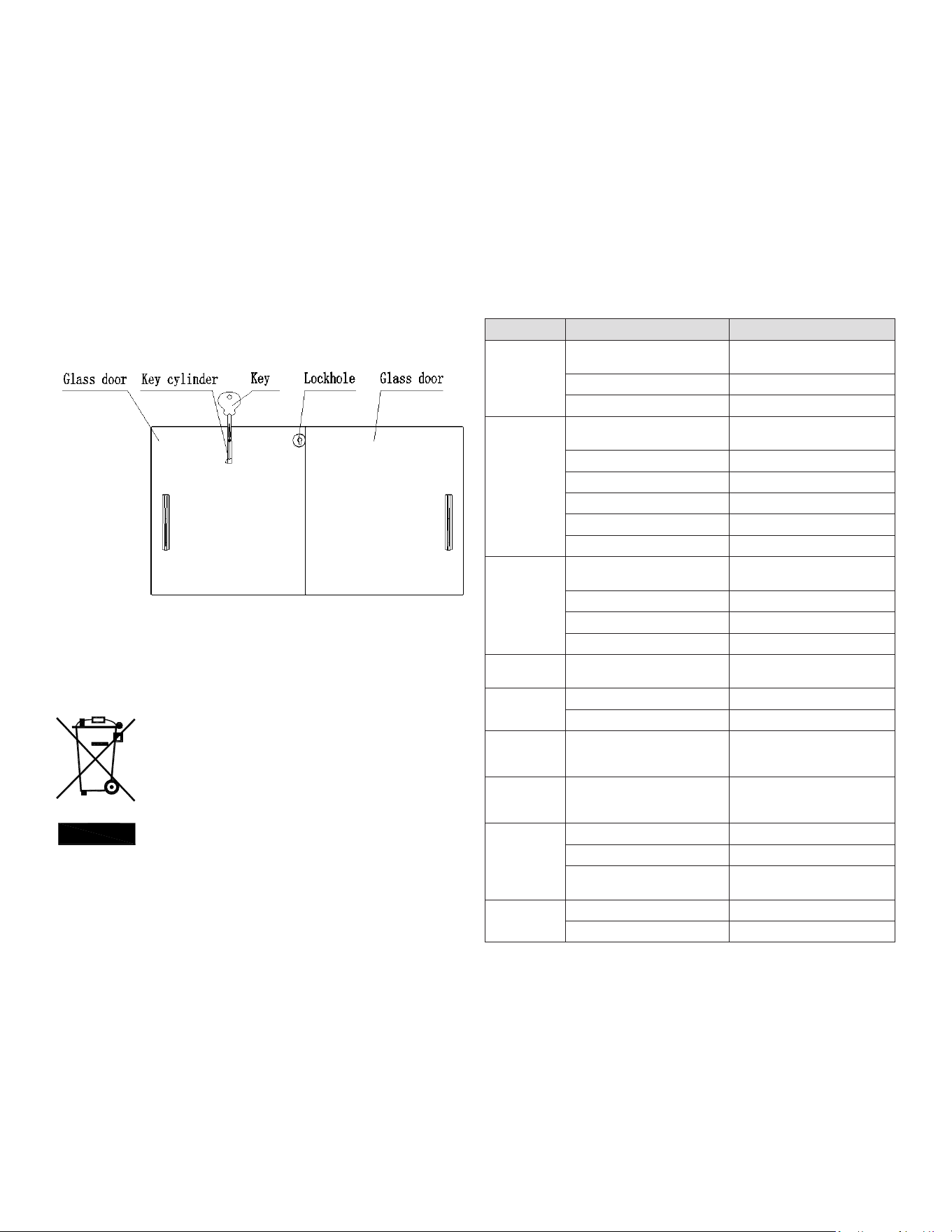
Wiring Diagram
KCICDC4FH
CALL FACTORY FOR REPLACEMENT PARTS:
866-339-8515
Wiring Diagram
KCICDC6FH
CALL FACTORY FOR REPLACEMENT PARTS:
866-339-8515
9 OM-DIPPING CABINET
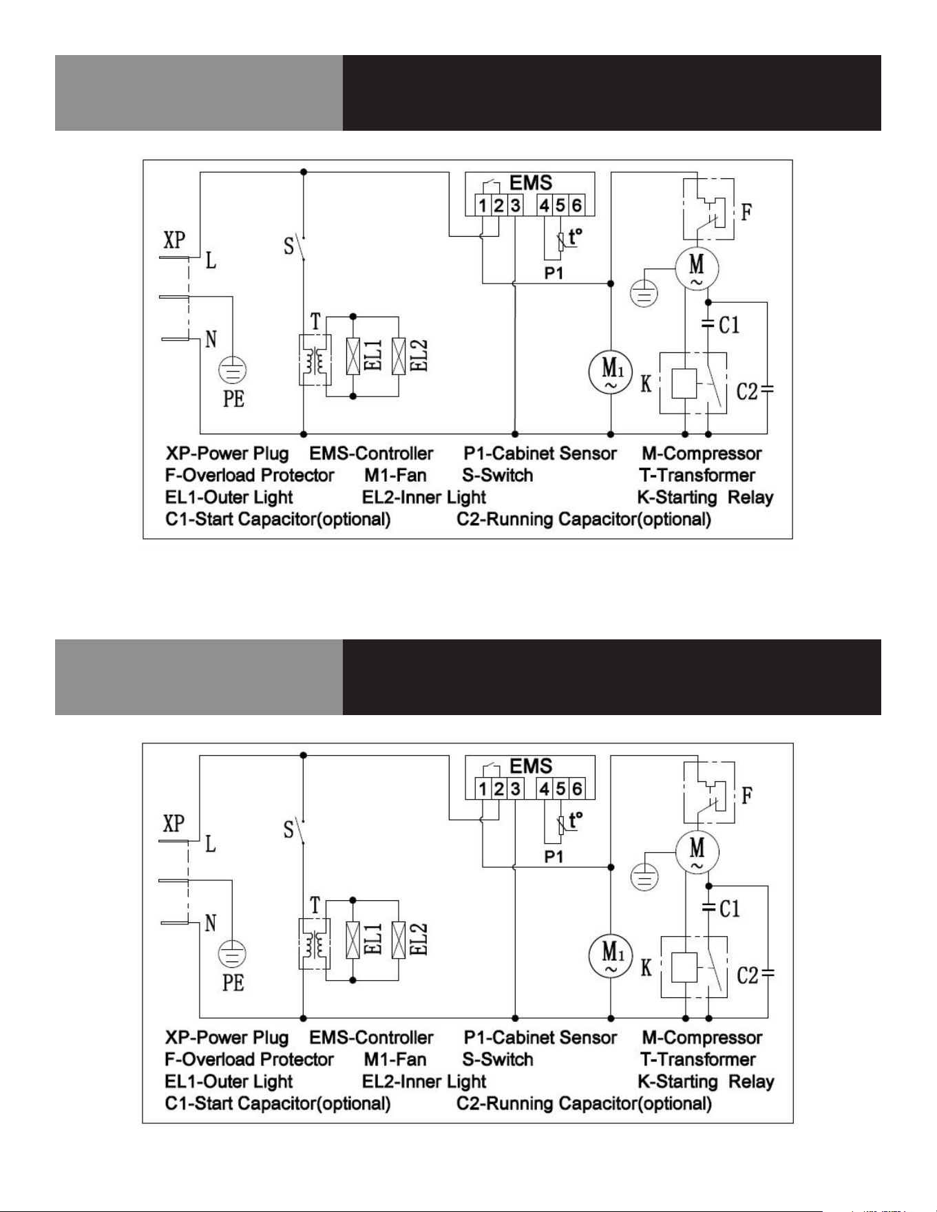
Wiring Diagram
KCICDC8FH
CALL FACTORY FOR REPLACEMENT PARTS:
866-339-8515
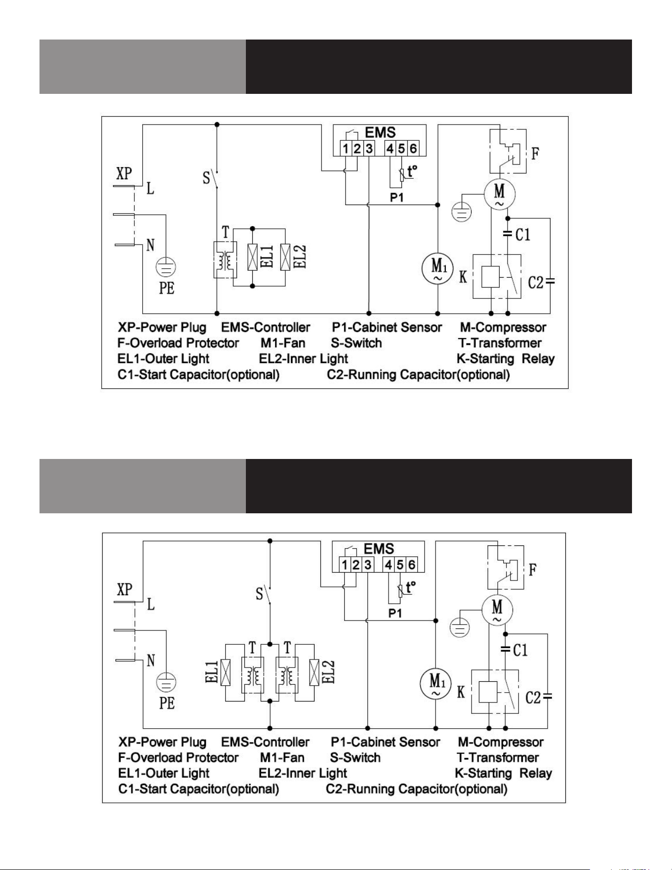
Wiring Diagram
KCICDC10FH
CALL FACTORY FOR REPLACEMENT PARTS:
866-339-8515

10 OM-DIPPING CABINET
Service Log
Model No: Purchased From:
Serial No: Location:
Date Purchased: Date Installed:
Purchase Order No: For Service Call:
Date Maintenance Performed Performed By

DESCRIPCIÓN DEL EQUIPO
N.º DE MODELO TIPO DE
REFRIGERANTE
PESO DEL
REFRIGERANTE,
G
V/HZ/PH AMPERIOS CAPACIDAD
ALMACENAMIENTO
(PIES3/M3)
TINA
DE 3
GALONES
HP BTU ONZAS
DE
CARGA
PESO DE
ENVÍO
LB/KG
ENCHUFE
NEMA
KCICDC4FH R290 68 115/60/1 1,3 6,0/ 0,17 4 1/5 1000 2,4 238/108 5-15P
KCICDC6FH R290 95 115/60/1 1,4 8,5/ 0,24 6 1/5 1350 3,35 304/138 5-15P
KCICDC8FH R290 110 115/60/1 2 10,9/ 0,30 8 1/4 1700 3,88 357/162 5-15P
KCICDC10FH R290 130 115/60/1 4,1 13,9/ 0,39 10 1/2 2230 4,59 439/199 5-15P
CONSERVE ESTE MANUAL PARA CONSULTAS FUTURAS
AVISO: Debido a un programa continuo de mejora del producto, Electrolux
Professional se reserva el derecho de realizar cambios en el diseño y las
especificaciones sin previo aviso.
AVISO: Lea detenidamente todo el manual
antes de la instalación. Si no se siguen ciertos procedimientos recomendados,
se rechazarán las reclamaciones de garantía.
RECEPCIÓN E INSPECCIÓN DEL EQUIPO
Si bien la mayoría de los equipos se envían embalados, se debe tener cuidado
durante la descarga para no dañar el equipo al desplazarlo hasta el lugar de
instalación.
1. Inspeccione visualmente el exterior del paquete y la plataforma o contenedor.
Si se observan daños se deben registrar y comunicar de inmediato al
transportista.
2. En caso de daños, abra e inspeccione el contenido con el transportista.
3. Si el exterior no está dañado, pero tras la apertura se observan daños ocultos en
el equipo, notifique al transportista. La notificación se debe realizar de manera
verbal y por escrito.
4. Solicite que la empresa de transporte inspeccione el equipo dañado. Esto debe
hacerse en el plazo de 10 días desde la recepción del equipo.
5. Cerciórese de revisar el alojamiento del compresor y de inspeccionar
visualmente el conjunto refrigerante. Compruebe si los conductos están seguros
y si la base sigue intacta.
6. Los transportistas pueden suministrar los formularios de notificación de daños si
se solicitan.
7. Conserve todo el material de embalaje hasta que se haya realizado o descartado
la inspección.
MANUAL DEL USUARIO
INFORMACIÓN IMPORTANTE, CONSÉRVESE PARA EL USUARIO
REV. D (05/25)
Este manual contiene información sobre:
HELADERA TIPO MOSTRADOR
ESTE MANUAL DEBE CONSERVARSE PARA CONSULTAS FUTURAS.
ASEGÚRESE DE LEER, COMPRENDER Y CUMPLIR LAS INSTRUCCIONES Y
ADVERTENCIAS QUE CONTIENE ESTE MANUAL.
POR SU SEGURIDAD No guarde ni utilice gasolina ni otros líquidos o
vapores inamables cerca de este equipo ni de ningún otro.
NOTIFIQUE LOS DAÑOS AL TRANSPORTISTA DE MANERA INMEDIATA Es
responsabilidad del destinatario inspeccionar el contenedor al recibirlo
y determinar la posibilidad de cualquier daño, incluidos los daños
ocultos. Electrolux Professional recomienda que, si sospecha que se
han producido daños, anote un comentario en el recibo del material.
Será responsabilidad del destinatario presentar una reclamación al
transportista. Es conveniente que lo haga de inmediato.
Servicio de fabricación/consultas 866-339-8515.
Estados Unidos y Canadá, 866-339-8515
4003 Collins Lane, Louisville, KY 40245
www.kelvinatorcommercial.com
Kelvinator Commercial es una marca comercial pendiente o registrada de Electrolux Consumer Products, Inc. y se utiliza bajo licencia de Electrolux Consumer Products, Inc.
La información que contiene este documento es actual y exacta en el momento de su impresión/creación. Consulte el sitio web de nuestra línea de productos para obtener
la información y las especificaciones más actualizadas. © 2025 Electrolux Professional, Inc. Todos los derechos reservados.
1. Dosel
2. Tapa de vidrio
3. Armario
4. Panel de control
5. Cable de alimentación
6. Rueda

2 OM-HELADERA TIPO MOSTRADOR
INSTALACIÓN
1. Cuando transporte la vitrina, el ángulo entre el cuerpo del compartimento y el
suelo no debe ser superior a 45° y nunca debe colocar la vitrina boca abajo.
2. No utilice ninguna de las partes externas como puntos de sujeción para
carga, por ejemplo, el condensador de la parte trasera o la puerta.
3. Cuando se instale o utilice la vitrina, se debe desechar todo el embalaje
(incluidas la placa y la espuma plástica).
4. Mantenga la vitrina estable para evitar vibraciones y ruidos.
5. La vitrina debe instalarse en un lugar con
buena ventilación, dejando un espacio
mínimo de 10 cm entre las paredes
circundantes y la pared del armario para
permitir la circulación del aire.
6. Debe colocarse lejos de fuentes de calor y
no expuesta a la luz solar directa para evitar
que disminuya la eficacia de la refrigeración.
7. Instale la vitrina en un lugar seco para evitar
que se oxide el cuerpo del compartimiento,
lo que podría afectar al aislamiento eléctrico.
IMPORTANTE - LÉASE PRIMERO - IMPORTANTE
SU SEGURIDAD Y LA DE LOS DEMÁS SON MUY IMPORTANTES.
EN ESTE MANUAL Y EN EL EQUIPO ENCONTRARÁ NUMEROSOS MENSAJES DE SEGURIDAD
IMPORTANTES. LEA Y CUMPLA SIEMPRE TODOS LOS MENSAJES DE SEGURIDAD.
ESTOS SON LOS SÍMBOLOS DE ALERTA SOBRE SEGURIDAD. ESTOS SÍMBOLOS
ALERTAN DE RIESGOS POTENCIALES QUE PUEDEN PROVOCAR HERIDAS O
MUERTE AL USUARIO O A OTRAS PERSONAS. TODOS LOS MENSAJES DE
SEGURIDAD IRÁN SEGUIDOS DE LOS SÍMBOLOS DE ALERTA DE SEGURIDAD Y
DE LAS PALABRAS "PELIGRO", "ADVERTENCIA" O "PRECAUCIÓN".
PELIGRO SIGNIFICA QUE EL INCUMPLIMIENTO DE ESTA INDICACIÓN DE
SEGURIDAD PUEDE PROVOCAR LESIONES GRAVES O MUERTE.
ADVERTENCIA SIGNIFICA QUE SI NO SE TIENE EN CUENTA ESTE AVISO DE
SEGURIDAD SE PUEDEN PRODUCIR DAÑOS IMPORTANTES EN EL PRODUCTO,
LESIONES PERSONALES GRAVES O MUERTE.
PRECAUCIÓN SIGNIFICA QUE EL INCUMPLIMIENTO DE ESTA INDICACIÓN
DE SEGURIDAD PUEDE PROVOCAR LESIONES PERSONALES LEVES O
MODERADAS, O DAÑOS MATERIALES O EN EL EQUIPO.
TODOS LOS MENSAJES DE SEGURIDAD ALERTAN SOBRE CUÁL ES EL PELIGRO POTENCIAL,
INDICAN CÓMO REDUCIR EL RIESGO DE LESIONES E INFORMAN DE LO QUE PUEDE
OCURRIR SI NO SE SIGUEN LAS INSTRUCCIONES.
ANTES DE UTILIZAR LA VITRINA DEBE COLOCARLA E INSTALARLA CORRECTAMENTE, COMO
SE INDICA EN ESTE MANUAL, POR LO QUE DEBE LEERLO ATENTAMENTE. PARA REDUCIR EL
RIESGO DE INCENDIO, DESCARGA ELÉCTRICA O LESIONES AL UTILIZAR LA VITRINA, ADOPTE
UNAS PRECAUCIONES BÁSICAS, ENTRE LAS QUE SE INCLUYEN LAS SIGUIENTES:
PELIGRO: ESTE ELECTRODOMÉSTICO NO ESTÁ DISEÑADO PARA QUE LO USEN
PERSONAS (INCLUIDOS NIÑOS) CON DISCAPACIDAD FÍSICA, SENSORIAL O
MENTAL, O CON EXPERIENCIA Y CONOCIMIENTO INSUFICIENTES, A MENOS
QUE UNA PERSONA RESPONSABLE DE SU SEGURIDAD LES SUPERVISE O LES
INSTRUYA EN EL USO DEL ELECTRODOMÉSTICO
PELIGRO: SE DEBE VIGILAR A LOS NIÑOS PARA IMPEDIR QUE JUEGUEN CON EL EQUIPO.
PELIGRO: RIESGO DE QUE NIÑOS QUEDEN ATRAPADOS: LA POSIBILIDAD DE QUE
UN NIÑO QUEDE ATRAPADO Y SE ASFIXIE SIGUE SIENDO UN RIESGO
IMPORTANTE. LAS VITRINAS APILADAS O ABANDONADAS SIGUEN SIENDO
PELIGROSOS, AUNQUE SE "DEJEN EN EL GARAJE SÓLO POR UNOS DÍAS".
PELIGRO: ANTES DE DESECHAR LA VITRINA ANTIGUA: RETIRE LAS PUERTAS. DEJE LOS
ESTANTES EN SU SITIO PARA QUE LOS NIÑOS NO PUEDAN INTRODUCIRSE
CON FACILIDAD.
PELIGRO: DISPONGA EL EQUIPO DE ACUERDO CON LA NORMATIVA LOCAL PARA
REFRIGERANTES INFLAMABLES Y GASES PROPULSORES.
PELIGRO: LA VITRINA DEBE UTILIZAR LA TOMA DE CORRIENTE CON CLAVIJA APARTE
PARA CONECTARSE CORRECTAMENTE A TIERRA, NUNCA CON EL TUBO DE
CALEFACCIÓN NI CON EL TUBO DE GAS DE CARBÓN.
PELIGRO: COLOQUE LA VITRINA DE MODO QUE LA TOMA QUEDE FÁCILMENTE ACCESIBLE.
PELIGRO: SI EL CABLE ELÉCTRICO SUFRE ALGÚN DAÑO, EL FABRICANTE, SU SERVICIO
TÉCNICO O UN PROFESIONAL TENDRÁN QUE CAMBIARLO PARA EVITAR RIESGOS.
PELIGRO: NO INTENTE REPARAR O SUSTITUIR NINGUNA PIEZA DE LA VITRINA A MENOS
QUE SE RECOMIENDE ESPECÍFICAMENTE EN EL MANUAL. PARA CUALQUIER
OTRO TIPO DE MANTENIMIENTO, DIRÍJASE A UN TÉCNICO PROFESIONAL.
ADVERTENCIA:
LA VITRINA NO DEBE COLOCARSE CERCA DE HORNOS, PARRILLAS U OTRAS
FUENTES DE CALOR INTENSO.
ADVERTENCIA:
MANTENGA LIBRES DE OBSTRUCCIONES LAS ABERTURAS DE VENTILACIÓN
DEL ALOJAMIENTO DEL EQUIPO O DE LA ESTRUCTURA EMPOTRADA.
ADVERTENCIA:
NO UTILICE DISPOSITIVOS MECÁNICOS NI OTROS MEDIOS PARA ACELERAR
EL PROCESO DE DESCONGELACIÓN, EXCEPTO LOS RECOMENDADOS POR EL
FABRICANTE.
ADVERTENCIA:
NO DAÑE EL CIRCUITO REFRIGERANTE.
ADVERTENCIA:
NO UTILICE DISPOSITIVOS ELÉCTRICOS DENTRO DE LOS COMPARTIMIENTOS
PARA ALIMENTOS DEL EQUIPO, SALVO SI SON DEL TIPO RECOMENDADO POR EL
FABRICANTE.
ADVERTENCIA:
ANTES DE PROCEDER A OPERACIONES DE LIMPIEZA Y MANTENIMIENTO,
ASEGÚRESE DE QUE LA LÍNEA DE ALIMENTACIÓN ELÉCTRICA DE LA UNIDAD
ESTÉ DESCONECTADA.
ADVERTENCIA:
NO CONECTE NI DESCONECTE EL ENCHUFE ELÉCTRICO CON LAS MANOS MOJADAS.
ADVERTENCIA:
NO GUARDE NI UTILICE GASOLINA U OTROS VAPORES O LÍQUIDOS INFLAMABLES
EN LAS PROXIMIDADES DE ESTA O DE OTRA VITRINA. NO LIMPIE NUNCA LOS
COMPONENTES DE LA VITRINA CON LÍQUIDO INFLAMABLE. LAS EMANACIONES
PUEDEN ORIGINAR RIESGO DE FUEGO O EXPLOSIÓN.
ADVERTENCIA:
SI EL VOLTAJE ES INESTABLE, ELIJA EL REGULADOR DE VOLTAJE AUTOMÁTICO
ADECUADO.
ADVERTENCIA:
CONECTE LA ALIMENTACIÓN PARA COMPROBAR LA VITRINA ANTES DE USARLA,
ESTA SE PUEDE UTILIZAR HASTA QUE LA TEMPERATURA DISMINUYA DE
MANERA EVIDENTE DESPUÉS DE 30 MINUTOS.
ADVERTENCIA:
DEBE AJUSTAR EL CONTROL DE TEMPERATURA SEGÚN LA TEMPERATURA QUE PREFIERA,
LA CANTIDAD DE ALIMENTOS ALMACENADOS Y LA TEMPERATURA AMBIENTE.
ADVERTENCIA:
ANTES DE COLOCAR LOS PRODUCTOS EN LA VITRINA, AJUSTE EL CONTROL DE
TEMPERATURA AL MÍNIMO Y DÉJELO FUNCIONAR HASTA QUE LA TEMPERATURA
INTERIOR DEL ARMARIO DESCIENDA A -18 ℃. A CONTINUACIÓN, INTRODUZCA
LOS PRODUCTOS Y, TRANSCURRIDAS 12 HORAS, AJUSTE EL CONTROL DE
TEMPERATURA AL VALOR NORMAL.
ADVERTENCIA:
NUNCA COLOQUE ALIMENTOS CALIENTES DIRECTAMENTE EN LA VITRINA SIN
HABERLOS DEJADO ENFRIAR PREVIAMENTE A TEMPERATURA AMBIENTE.
ADVERTENCIA:
EL MATERIAL DEBE COLOCARSE EN LA VITRINA DE FORMA PARCIAL, CADA LOTE
NO DEBE SUPERAR LA CIFRA EQUIVALENTE A LA CAPACIDAD (L) DIVIDIDA POR 20.
ADVERTENCIA:
NO LLENE LA VITRINA NI LA ABARROTE; LAS PIEZAS GRANDES DE CARNE
DEBEN DIVIDIRSE EN VARIAS PARTES MÁS PEQUEÑAS. DEBE HABER UN
ESPACIO RAZONABLE ENTRE LOS ALIMENTOS PARA QUE SE CONGELEN MEJOR.
ADVERTENCIA:
SI ES NECESARIO CORTAR LA ALIMENTACIÓN ELÉCTRICA, ESPERE AL MENOS 5
MINUTOS ANTES DE VOLVER A ENCENDER EL EQUIPO PARA EVITAR DAÑOS EN
EL COMPRESOR.
ADVERTENCIA:
LOS PRODUCTOS ALMACENADOS DEBEN ENVASARSE BIEN EN BOLSAS DE
PLÁSTICO PARA EVITAR QUE SE MEZCLEN LOS OLORES Y SE PIERDA HUMEDAD,
Y PARA REDUCIR LA FORMACIÓN DE ESCARCHA EN POCO TIEMPO.
ADVERTENCIA:
EN LA VITRINA NO SE PUEDE INTRODUCIR CERVEZA, BEBIDAS, FLORES FRESCAS,
MEDICAMENTOS NI INYECCIONES.
ADVERTENCIA:
SI DESEA CONSERVAR HELADOS U OTROS ALIMENTOS QUE SE CONGELAN CON
FACILIDAD, AJUSTE EL CONTROL DE TEMPERATURA AL MÍNIMO.
ADVERTENCIA:
TENEMOS UNA POLÍTICA DE MEJORA CONTINUA DE NUESTROS PRODUCTOS
Y NOS RESERVAMOS EL DERECHO A MODIFICAR LOS MATERIALES Y LAS
ESPECIFICACIONES SIN PREVIO AVISO. PARA CONFIRMAR LOS PARÁMETROS
ESPECÍFICOS, CONSULTE LA ETIQUETA DE CLASIFICACIÓN DEL PRODUCTO.
ADVERTENCIA:
SE DEBERÁ TRATAR EL PRODUCTO CUANDO SEA DESECHADO/RECUPERADO
POR CENTROS PROFESIONALES DE DESECHOS/RECICLAJE.
ADVERTENCIA:
TEMPERATURA AMBIENTE DE APLICACIÓN DEL PRODUCTO HASTA 43 ºC.
3 OM-HELADERA TIPO MOSTRADOR
FUNCIONAMIENTO
PANEL DE CONTROL
Termostato electrónico
CAREL SERIES REFRIGERATION CONTROL – FIELD SUPPORT GUIDE
1. Overview of the Easy control’s display and buttons:
2. Wiring the control’s connections correctly:
Carel controls come in a wide variety of different configurations, often
customized for the OEM appliance manufacturer. A label found on top of the control will show a wiring guide and electrical
specifications for the specific model. When replacing the control, DO NOT ASSUME that the numbered terminals will always serve
the same function as the previous control installed. Carefully check all connections according to the labels / symbols shown
underneath each numbered contact.
Common Configurations: PJEZS* Models – Medium Temp PJEZC* Models – Low Temp
Carefully note the following connections available on your model, and connect the wires accordingly.
Temperature probe input(s)
Control probe (AMB) and optional defrost probe (DEF), with a common
Digital input
Configurable input for alarm, defrost, curtain etc. (Parameter A4)
Compressor output
Contact points may vary across different control models
Fan output
Contact points may vary across different control models
Defrost output
Contact points may vary across different control models
Auxiliary output
Contact points may vary across different control models
Line voltage to outputs
L
Typically isolated from supply voltage, requiring its own connection
Supply voltage
L/N
Line and neutral supply wires, most commonly points 6 and 7
3. Viewing and changing the set point:
Press and hold the red SET button for 1 second to view current set point,
and release immediately after it is displayed. (Display may flash, indicating the value can be changed.)
Press UP and DOWN arrows to change value and press SET again to store new value.
PANTALLA
N.º DE
TECLA
FUNCIÓN
FUNCIONAMIENTO NORMAL
PUESTA EN
MARCHA
ENCENDIDO APAGADO PARPADEO
1 Compresor Encendido Apagado Llamada Encendido
2 Ventilador Encendido Apagado Llamada Encendido
3
Descongelación
Encendido Apagado Llamada Encendido
4
Salida
auxiliar (AUX)
Salida
activada
Salida
inactiva
-
Encendido
5 Reloj (RTC)
RTC disponible,
habilitado
(tEN=1) y al
menos se ha
establecido
banda horaria
RTC no disponible
o no habilitado
(tEN=0) o no se
ha establecido
ninguna banda
horaria
RTC disponible,
habilitado
(tEN=1) y al
menos se ha
establecido
banda horaria
ENCENDIDO
(si el
reloj está
instalado)
6 Alarma
Alarma en
curso
Sin alarma
en curso
-
Encendido
7 Dígitos
Tres dígitos con punto decimal y rango de -199 a 999. Consulte
los parámetros /4, /5, /6 para conocer el tipo de sonda que se
muestra, los valores en °C/°F y el punto decimal.
TECLADO (MODELOS C, S, X, Y)
N.º DE
TECLA
FUNCIONAMIENTO NORMAL
PUESTA EN MARCHA
PRESIONANDO
SOLO LA TECLA
PRESIONANDO CON
OTRAS TECLAS
1
Más de 3 s:
Encendido/apagado
Presionada junto
con 3 activa /
desactiva el ciclo
continuo
-
2
- 1 s: muestra/ajusta el
punto de referencia
- Más de 3 s: se
accede al menú
de configuración
de parámetros
(introduzca la
contraseña 22)
- Silencia la alarma
sonora (zumbador)
-
Durante 1 s
RESTABLECE
el ajuste EZY
actual
Al presionarlas
juntas (2 y 3),
se activa el
procedimiento de
restablecimiento
de parámetros.
3
Más de 3 s: activa /
desactiva la
descongelación
Presionada junto
con 1 activa /
desactiva el ciclo
continuo
Durante 1 s
muestra la
versión del
firmware
CONFIGURACIONES PRELIMINARES
Una vez realizadas las conexiones eléctricas, basta con encender el
controlador para que entre en funcionamiento. Se recomienda comprobar que
la pantalla no muestre ninguna señal de alarma (consulte "Tabla de alarmas
y señales") y, a continuación, ajustar los parámetros según se desee. Los
parámetros principales son los siguientes (consulte la sección de funciones y
parámetros para obtener más detalles):
PARÁMETROS DE CONTROL
St Punto de ajuste
rd Diferencial de punto de ajuste
PARÁMETROS DE DESCONGELACIÓN
d0
Tipo de descongelación
dl
Intervalo entre dos descongelaciones
dt
Temperatura final de descongelación
dp
Duración máxima de descongelación
PARÁMETROS DE ALARMA
Ad
Retardo de alarma de temperatura
AL
Umbral/desviación de alarma de baja temperatura
AH
Umbral/desviación de alarma de alta temperatura
A0
Alarma y diferencial de temperatura del ventilador
FUNCIONES DISPONIBLES DESDE EL TECLADO:
Encendido y apagado:
Encendido del instrumento: presione ARRIBA durante más de 3 segundos (al
presionar la tecla, la pantalla muestra ON).
Apagado del instrumento: presione ARRIBA durante más de 3 segundos. La
pantalla muestra el mensaje "OFF", alternando con la temperatura medida por
la sonda configurada.
En estado desactivado, las siguientes funciones están desactivadas (si están
disponibles en el modelo):
INDICADOR DE ALARMA:
con código(s) mostrado(s)
TECLA DE ENCENDIDO: manténgala
presionada para cambiar el estado de
"encendido/apagado".
DESCONGELACIÓN MANUAL:
mantenga la presión durante 3 segundos
para iniciar la descongelación.
DESPLÁCESE HACIA ABAJO cuando
seleccione parámetros o cambie ajustes.
TECLA SET: manténgala presionada
durante 1 segundo para mostrar/cambiar
el punto de ajuste.
Mantenga la presión durante 3-5 segundos
para acceder al modo de programación
de parámetros.
Presione para SILENCIAR una alarma
sonora.
INDICADOR DE FUNCIONES:
estable = en funcionamiento
Parpadeo = retraso temporizado
pendiente
INDICADOR DE RELOJ:
el temporizador está activo
Compresor (refrigeración)
DIAGRAMA DE CABLEADO: impreso en la superficie
superior del control.
Ventilador del evaporador
Descongelación
Salida AUX
(Configurada por el instalador/OEM)
DESPLÁCESE HACIA ARRIBA cuando
seleccione parámetros o cambie ajustes.

4 OM-HELADERA TIPO MOSTRADOR
• control del compresor / ajuste de servicio / ciclo continuo
• descongelación
• control del ventilador
• alarmas: ‘LO’, ‘HI’, ‘IA’, ‘cht’, ‘CHT’
• interruptor de puerta: A4=7/8
• zumbador (cuando esté disponible)
Mientras esté habilitado lo siguiente:
• indicador de temperatura, alternando con el mensaje "OFF"
• pantalla y configuración de parámetros
• alarmas: “E0”, “E1”, “E2”
• se actualiza el temporizador interno relacionado con el parámetro "dI". Si
"dI" expira en estado OFF, se realiza una descongelación al reiniciar.
• gestión de relés auxiliares, solo en las siguientes configuraciones:
– H1= = 1/2 (solo alarma “E0”)
– H1= 3, A4= 6
Nota: al salir del estado OFF, los siguientes ajustes se ponen a cero (es decir,
no se guardan antes de apagar): histéresis y gestión de la alarma del ventilador
del evaporador (A0), histéresis del control de temperatura (rd), histéresis de
prealarma de cht (AE). Además, los retrasos se establecen en cero para la
visualización de las alarmas de temperatura (Ad, d8, c6), goteo (dd) y postgoteo
(Fd).
ADVERTENCIAS:
• cuando se conecta por primera vez, el controlador ya está encendido y listo
para ser utilizado.
• el instrumento se puede encender desde un PC supervisor y a través de
un contacto externo (ajuste A4= 5). Este último tiene prioridad sobre los
demás modos.
Conguración del punto de ajuste (valor de temperatura que se desee):
El dispositivo controlador regula la temperatura deseada (punto de ajuste)
dentro del armario o la cámara frigorífica de forma directa y dinámica.
Para ver y modificar el punto de ajuste:
• presione SET (ajustes) durante 1 s, el valor establecido comenzará a
parpadear (indicando que el valor se puede cambiar).
• aumente o reduzca el valor con las teclas ARRIBA o ABAJO.
• presione SET (ajustes) para confirmar el nuevo valor.
• mantenga presionado SET durante 5 segundos para guardar los cambios
realizados; la pantalla volverá a mostrar la lectura de temperatura.
Nota: Si el último paso no se realiza correctamente, es posible que se pierdan
todos los cambios realizados en los parámetros.
Descongelación manual:
- No disponible en los modelos Easy Thermometer (M) y Easy Compact.
Presione ABAJO durante más de 3 s (se activa solo si las condiciones de
temperatura son adecuadas, para facilitar la separación solo si la salida de luz
no está configurada, H1≠4).
Ciclo continuo:
- No disponible en los modelos Easy Thermometer (M) y Easy Compact.
Presione ARRIBA+ABAJO durante más de 3 s (se activa solo si las condiciones
de temperatura son adecuadas y para facilitar la separación solo cuando
H6≠0). El ciclo continuo se utiliza para mantener activa la refrigeración en el
armario o la cámara fría, independientemente de la temperatura interior de la
unidad. Esto puede ser útil para bajar rápidamente la temperatura por debajo
del valor establecido.
FUNCIONES Y PARÁMETROS
PARÁMETROS DE CONTROL COMUNES / DEFINICIONES
PARÁM. DESCRIPCIÓN
PS Contraseña
/2 Estabilidad de medición de sonda
/4
Seleccionar sonda mostrada por defecto [ 1=Amb; 2=Def; 3=Dig.IN]
/5
Seleccionar temperatura mostrada en °C/°F [0=°C; 1=°F] (consulte la
nota a continuación)
/6
Desactivar el punto decimal [0 = temperatura mostrada en décimas de
grado; 1 = temperatura mostrada SIN décimas de grado]
/C1
Desviación/calibración de la sonda 1 (valor de temperatura + o -)
/C2
Desviación/calibración de la sonda 2 (valor de temperatura + o -)
St
Punto de ajuste
rd
Diferencial de control (St + rd = Comp Cut-IN)
r1
Valor MÍNIMO admisible de punto de ajuste
r2 Valor MÁXIMO admisible de punto de ajuste
PARÁMETROS DE DESCONGELACIÓN / DEFINICIONES
PARÁM. DESCRIPCIÓN
d0
Tipo de descongelación [0=elec. por TEMP; 1=gas caliente por TEMP;
2=elec. por TIEMPO; 4= TEMP con TIEMPO]
dl
Horas entre los inicios automáticos de descongelación (intervalos de descongelación)
dt
Punto de ajuste de fin de descongelación / umbral de temperatura de
descongelación con control de temperatura (se ignora si d0=2 o 3)
dp
Duración máxima del descongelación (en minutos) (tiempo MÁXIMO si d0=4)
PARÁMETROS DE ALARMA / DEFINICIONES
PARÁM. DESCRIPCIÓN
A0
Diferencial de temperatura entre alarma y ventilador [0=AL y AH son
valores absolutos]
AL Valor de alarma de BAJA temperatura
AH
Valor de alarma de ALTA temperatura
Ad
Retardo de alarma de temperatura
A4
Configuración de la entrada digital [0=desactivada; 1=alarma externa;
2=descongelación activada; 4=modo cortina/noche; 5=encendido/
apagado remoto; 6=salida AUX; 9=modo directo/inverso]
A7
Retardo de alarma de entrada digital
A8
Activar alarma "Ed" (fin de descongelación por tiempo de espera)
AC
Alarma de condensador sucio en el punto de ajuste
AE
Alarma de temperatura diferencial de condensador sucio
Acd
Retardo de alarma de condensador sucio
OTROS PARÁMETROS / DEFINICIONES
PARÁM. DESCRIPCIÓN
H0 Dirección serie
H1
Configuración de salida AUX [0=desactivada; 1=alarma N.C.; 2=alarma N.O.;
3= entrada digital]
H2
Habilitar teclado [0=habilitado] o [1=deshabilitado]
H4
Desactivar zumbador de alarma [0=activado] o [1=desactivado]
Los códigos de parámetros que no se encuentren pueden haber sido eliminados por
el fabricante original durante la personalización. Omítalos por ahora y, si persisten los
problemas operativos, consulte al fabricante del equipo para obtener asesoramiento.
Nota: al cambiar el modo de temperatura entre CELCIUS y FAHRENHEIT (parámetro
/5), asegúrese de comprobar/restablecer los parámetros comunes resaltados,
además del punto de ajuste. Los valores de temperatura almacenados no se
convierten automáticamente después de cambiar el ajuste "/5".
5 OM-HELADERA TIPO MOSTRADOR
CICLO CONTINUO
El ciclo continuo se utiliza para mantener la refrigeración activa de forma
continua, independientemente de la temperatura interior de la unidad. La función
se utiliza para reducir rápidamente la temperatura del producto, incluso por
debajo del punto de ajuste, por ejemplo, después de llenar los armarios. En esta
fase, la temperatura puede descender por debajo del punto de ajuste.
Para activar o desactivar el ciclo continuo desde el teclado, consulte la sección
de funciones del teclado.
la pantalla muestra "cc" y el icono parpadea (2 parpadeos, pausa).
cc: duración del ciclo continuo
Representa el tiempo en horas que el compresor funciona de forma continua
para bajar la temperatura, incluso por debajo del punto de ajuste. Si cc=0 el
ciclo continuo no está activado. El controlador sale del procedimiento de ciclo
continuo una vez transcurrido el tiempo establecido para el parámetro "cc" o
al alcanzar la temperatura mínima (consulte la alarma de temperatura mínima,
parámetro AL).
c6: alarma de temperatura omitida tras ciclo continuo
Es el tiempo en horas durante el cual todas las alarmas de temperatura
quedan desactivadas tras un ciclo continuo. Si, tras el ciclo continuo, la
temperatura de la unidad refrigerada desciende por inercia por debajo del
umbral mínimo de temperatura (punto de ajuste AL), la activación de la alarma
de baja temperatura se retrasa durante el tiempo c6. En cualquier caso, el ciclo
continuo se desactiva a la temperatura (punto de ajuste -AL).
ALARMAS Y SEÑALES
Cuando se activa una alarma, la pantalla muestra el mensaje correspondiente
que parpadea alternativamente con la temperatura; también se activan el
zumbador y el relé de alarma si están instalados y habilitados.
Todas las alarmas tienen reinicio automático (es decir, se detienen cuando
desaparecen las causas), excepto la alarma "CHt", que tiene reinicio manual
(encendido/apagado del instrumento mediante la tecla UP o desconectando la
fuente de alimentación). Al presionar la tecla SET se silencia el zumbador, mientras
que el código mostrado y el relé de alarma solo se activan cuando se han resuelto
las causas de la alarma. Los códigos de alarma se muestran en la tabla siguiente:
TABLA DE ALARMAS Y SEÑALES
PARÁM.
RELÉ DE ZUMBADOR
Y ALARMA
DESCRIPCIÓN
RESTABLECIMIENTO
CAUSA/NOTA
E0 Activo
Error de sonda
1 = sonda de
control
Automático
La sonda no funciona:
la señal de la sonda
está interrumpida o en
cortocircuito; o la sonda
no es compatible con el
instrumento.
E1 No activo
Error de sonda
2 = sonda de
descongelación/
evaporador
Automático
La sonda no funciona:
la señal de la sonda
está interrumpida o en
cortocircuito; o la sonda
no es compatible con el
instrumento.
E2
No activo
Error de sonda
3 = sonda de
condensador/
producto
Automático
La sonda no funciona:
la señal de la sonda
está interrumpida o en
cortocircuito; o la sonda
no es compatible con el
instrumento.
IA Activo
Alarma externa Automático
Alarma inmediata o
retardada desde entrada
digital multifunción.
• Compruebe la entrada
multifunción y los
parámetros A4 y A7.
dOr Activo
Alarma de
puerta abierta
Automático
Compruebe la entrada
multifunción y los
parámetros A4 y A7.
TABLA DE ALARMAS Y SEÑALES
PARÁM.
RELÉ DE ZUMBADOR
Y ALARMA
DESCRIPCIÓN
RESTABLECIMIENTO
CAUSA/NOTA
LO Activo
Alarma de baja
temperatura:
enfriamiento
por debajo del
punto de ajuste
Automático
La sonda ha medido
una temperatura inferior
al punto de ajuste en
un valor que supera el
parámetro AL.
• Compruebe los
parámetros AL, Ad y A0.
HI
Activo
Alarma de alta
temperatura
Automático
La sonda ha medido una
temperatura superior
al punto de ajuste en
un valor que supera el
parámetro AH.
• Compruebe los
parámetros AH, Ad y A0.
EE No activo
Error de
parámetro de
unidad
No es posible
Error de lectura de
parámetro de unidad.
Si el fallo persiste, es
necesario sustituir
el controlador. Si el
mensaje desaparece, se
puede seguir utilizando.
EF No activo
Error de
parámetro
operativo
Manual
Error de lectura de
parámetro operativo.
Si el fallo persiste, es
necesario sustituir
el controlador. Si el
mensaje desaparece, se
puede seguir utilizando.
Ed No activo
Descongelación
finalizada por
tiempo agotado
La primera
descongelación
finalizó
correctamente
La última descongelación
finalizó tras superar la
duración máxima, en
lugar de al alcanzar el
punto de ajuste de fin de
descongelación.
• Compruebe los
parámetros dt, dP y d4
• Compruebe la eficacia
de la descongelación
dF No activo
Descongelación
en marcha
Automático
Descongelación en marcha:
• No se trata de una señal
de alarma, sino de un
mensaje que indica que el
instrumento está realizando
una descongelación. Solo se
muestra si d6= 0.
cht No activo
Prealarma de
condensador
sucio
Automático
Prealarma de condensador
sucio:
• Compruebe los parámetros
A4, Ac, AE y Acd.
CHt
Activo
Alarma de
condensador
sucio
Manual
Alarma de condensador
sucio:
• Compruebe los parámetros
A4, Ac, AE y Acd.
ALMACENAMIENTO
1. El equipo es adecuado para almacenar helados y alimentos precocinados
congelados.
2. No debe llenarse por encima de la marca de apilamiento situada en el
interior de la vitrina.
3. Si no hay adhesivo de línea de carga, tome como referencia la parte
superior de la cesta colocada.
LÍNEA DE CARGA
6 OM-HELADERA TIPO MOSTRADOR
DESCONGELACIÓN
1. Descongele cuando el espesor de la escarcha en la pared del armario
alcance los 5 mm para optimizar la capacidad de congelación.
2. Gire el control de temperatura al punto más bajo durante 5-6 horas antes
de descongelar.
3. Corte la corriente y saque los alimentos, utilice la eliminación de escarcha,
no emplee herramientas afiladas.
4. Después de descongelar, limpie la pared con un paño seco y, a
continuación, conecte la alimentación eléctrica.
Los siguientes fenómenos son normales
1. Habrá sonidos de agua en movimiento cuando el refrigerante esté funcionando.
2. Los alimentos congelados no se descongelan aunque se desconecte la
corriente durante mucho tiempo.
3. Cuando la humedad ambiental es demasiado alta, se condensa rocío en la
superficie de la vitrina.
4. Cuando la máquina está en funcionamiento, el condensador y el compresor
se calientan.
CERRADURA
1. Puede bloquear el congelador: El primer paso es introducir la llave y el
cilindro de la llave en el orificio de la cerradura; el segundo paso es girar la
llave 90° en sentido horario; a continuación, se saca la llave.
2. Puede desbloquear el congelador: Primer paso: gire la llave 90° en sentido
antihorario; segundo paso: saque la llave y el cilindro de la cerradura.
NOTAS: El bloqueo es una de las opciones que su producto tal vez no tenga.
MANTENIMIENTO
1. No abra la puerta con frecuencia ni durante mucho
tiempo para ahorrar energía.
2. Nunca deje objetos pesados o calientes sobre la vitrina
para evitar deformaciones.
3. Desconecte la alimentación eléctrica antes de limpiar.
4. Para limpiar la vitrina, utilice un paño suave
humedecido con un detergente suave y agua caliente.
5. Utilice agua templada para limpiar las manchas de aceite o zumo de frutas
de la junta magnética con el fin de mantener su elasticidad. Aplique un
poco de talco para prolongar su vida útil.
6. No deje la vitrina sin usar durante mucho tiempo. Para dejar de utilizarla,
desconecte primero la alimentación eléctrica, limpie el interior y deje la
puerta abierta durante 2-3 días para que se seque.
ELIMINACIÓN CORRECTA DE ESTE PRODUCTO
Esta marca indica que el producto no debe eliminarse junto con los residuos
domésticos. Para evitar el deterioro del medio ambiente o riesgos para la
salud humana por la eliminación incorrecta de residuos, recíclelo de manera
responsable para fomentar la reutilización sostenible de los recursos materiales.
Para devolver el aparato usado, utilice los sistemas de devolución y recogida o
póngase en contacto con el distribuidor al que se adquirió. Él se encargará del
reciclaje del producto de conformidad con las normas medioambientales.
REPUESTOS
Para pedir piezas, póngase en contacto con un agente de servicio autorizado.
Indique la designación del modelo, el número de serie, la descripción de la
pieza, el número de pieza, la cantidad y, si procede, el voltaje y la fase.
CONTÁCTENOS
Para obtener servicio, la unidad debe registrarse primero en Kelvinator Commercial.
com. Una vez registrada, llame al 866-339-8515 para solicitar asistencia.
SOLUCIÓN DE PROBLEMAS
PROBLEMA CAUSA SOLUCIÓN
Descongelación
El control de temperatura está
en el punto más alto (punto 1).
Ajuste el control de temperatura.
El enchufe y la toma no están
bien conectados.
Conéctelos bien
Fusible roto Cambie el fusible
El compresor
no se detiene
El control de temperatura está
en el punto más bajo (punto 7).
Ajuste el control de temperatura.
Demasiadas cosas guardadas al
mismo tiempo
Reduzca la cantidad
Escarcha gruesa Descongelación
Demasiadas veces de apertura
de la puerta
Reduzca las aperturas de la
puerta
Demasiado cerca de la pared Lejos de la pared
Cerca de fuentes de calor o del sol Cambie la ubicación
Demasiado
calor
El control de temperatura está
en el punto más alto (punto 1).
Ajuste el control de temperatura.
Demasiadas cosas guardadas al
mismo tiempo
Reduzca la cantidad
Demasiadas veces de apertura
de la puerta
Reduzca las aperturas de la
puerta
Cerca de fuentes de calor o del sol Cambie la ubicación
Demasiado
frío
El control de temperatura está
en el punto más bajo (punto 7).
Ajuste el control de temperatura.
Ruido fuerte
o vibración
violenta
El piso no es plano Cambie la ubicación
Tubos de refrigeración
conectados
Sepárelos
Presencia de
agua en el
piso.
El agua de condensación de
las tapas cae por el tubo de
desagüe al piso
Vacíe el agua del colector de
agua
Condensación
de agua en las
tapas
La humedad ambiental es
demasiado alta
Seque las tapas con un paño
suave.
Formación
excesiva de
hielo en el
armario
Demasiadas veces de apertura
de la puerta
Reduzca las aperturas de la
puerta
Las puertas no están cerradas Cierre las puertas
El agua de condensación de las
tapas cae dentro.
Desatasque el tubo de desagüe
con un alambre, descongele.
La luz no
enciende
El enchufe y la toma no están
bien conectados.
Conéctelos bien
El interruptor de la luz está
desconectado
Accione el interruptor de la luz
NOTA: Si no puede resolver los problemas según la tabla anterior, póngase en
contacto con el servicio posventa, no manipule la unidad.
Puerta de
vidrio
Orificio de
llave
LlaveCilindro de llave
Puerta de
vidrio

7 OM-HELADERA TIPO MOSTRADOR
GARANTÍA
El equipo cuenta con
garantía limitada de tres (3) años. Durante tres (3) años
a partir de la fecha original de compra, Electrolux Professional, Inc. pagará todos
los costos, excepto los establecidos a continuación, de reparación o sustitución
de cualquier pieza de este equipo que resulte defectuosa en materiales o mano
de obra, cuando dicho equipo se instale, utilice y mantenga de acuerdo con las
instrucciones proporcionadas. Los equipos fabricados con compresor tienen una
garantía adicional de dos (2) años que solo se aplica al compresor.
EXCLUSIONES
ESTA GARANTÍA NO CUBRE LO SIGUIENTE:
1. Productos en los que el número de serie original se ha eliminado, alterado o no
pueda observarse con facilidad.
2. Desgaste normal y deterioro gradual.
3. Producto que ha sido transferido de su propietario original a otra parte o
trasladado fuera de EE.UU. o Canadá.
4. Óxido en el interior o el exterior de la unidad.
5. Productos adquiridos “tal cual”.
6. Pérdidas de alimentos debidas a desperfectos de nevera o congelador.
7. Daños sufridos en cualquier momento del transporte.
8. Llamadas al servicio técnico que no se refieran a desperfectos o defectos de
material o elaboración, o respecto a equipos utilizados de un modo distinto al
indicado en las instrucciones suministradas.
9. Llamadas al servicio técnico para corregir la instalación del equipo o para
solicitar instrucciones de uso.
10. Gastos para hacer accesible el equipo para su mantenimiento, como la retirada
de molduras, armarios, estantes, etc., que no formen parte del equipo cuando
se envía de fábrica.
11. Llamadas al servicio técnico para sustituir lámparas, filtros de aire, filtros de
agua y otros consumibles, o perillas, asas u otras piezas ornamentales.
12. Recargos derivados, entre otras cosas, de trabajo en horas extra, fin de
semana o festivos, peajes, trasbordos o kilometraje por llamadas al servicio
técnico desde zonas alejadas, incluido el Estado de Alaska.
13. Daños ocasionados al acabado del equipo o a su ubicación producidos durante
la instalación, entre otros, a pisos, armarios, paredes, etc.
14. Daños provocados por: servicios realizados por empresas de servicios
no autorizadas; uso de repuestos que no sean originales de Electrolux
Professional, Inc. o repuestos obtenidos de personas que no sean empresas
de servicios autorizadas; o causas externas como uso incorrecto o indebido,
alimentación eléctrica inadecuada, accidentes, incendios o desastres
naturales.
15. Los equipos utilizados por concesionarios o distribuidores en un remolque u
otro vehículo motorizado, o en distintas ubicaciones, tienen garantía de un
(1) año con limitación de piezas y mano de obra. Los equipos fabricados con
compresor tienen una garantía adicional de cuatro (4) años que solo se aplica
al compresor.
EXCLUSIÓN DE GARANTÍAS IMPLÍCITAS; LIMITACIÓN DE RECURSOS
EL ÚNICO Y EXCLUSIVO RECURSO DEL CLIENTE SEGÚN LOS TÉRMINOS DE ESTA
GARANTÍA LIMITADA SERÁ LA REPARACIÓN O SUSTITUCIÓN DEL PRODUCTO
SEGÚN SE ESTIPULA EN EL PRESENTE DOCUMENTO. LAS RECLAMACIONES
BASADAS EN GARANTÍAS IMPLÍCITAS, INCLUIDAS LAS GARANTÍAS DE
COMERCIABILIDAD O DE IDONEIDAD PARA UN FIN DETERMINADO, ESTÁN
LIMITADAS A UN (1) AÑO O AL PERÍODO MÁS CORTO PERMITIDO POR LEY,
AUNQUE NO INFERIOR A UN (1) AÑO. ELECTROLUX PROFESSIONAL, INC.
NO SERÁ RESPONSABLE DE DAÑOS CONSECUENTES O FORTUITOS COMO
DAÑOS A LA PROPIEDAD Y GASTOS OCASIONALES DERIVADOS DE CUALQUIER
INCUMPLIMIENTO DE ESTA GARANTÍA LIMITADA ESCRITA O DE CUALQUIER
GARANTÍA IMPLÍCITA. ALGUNOS ESTADOS Y PROVINCIAS NO PERMITEN
LA EXCLUSIÓN O LIMITACIÓN DE DAÑOS ACCIDENTALES O DERIVADOS NI
LIMITACIONES ACERCA DE LA DURACIÓN DE LA GARANTÍA IMPLÍCITA, DE MODO
QUE ES POSIBLE QUE LAS LIMITACIONES O EXCLUSIONES ARRIBA MENCIONADAS
NO SE APLIQUEN A SU CASO. ESTA GARANTÍA ESCRITA LE OTORGA DERECHOS
LEGALES ESPECÍFICOS. ES POSIBLE QUE TAMBIÉN DISFRUTE DE OTROS
DERECHOS QUE VARÍEN DE UNA JURISDICCIÓN A OTRA.
Si necesita servicio
Para obtener servicio, la unidad debe registrarse primero en
KelvinatorCommercial.com. Una vez registrada, llame al 866-339-8515 para
solicitar asistencia.
Esta garantía sólo se aplica en EE.UU. y Canadá y está garantizada por Electrolux
Professional, Inc.
Para instalaciones fuera de EE.UU. y Canadá, póngase en
contacto con su proveedor local de equipos para conocer los detalles de la
garantía.
Electrolux Professional, Inc. no autoriza a persona alguna a cambiar o añadir
obligaciones a esta garantía. Las obligaciones de servicio y repuestos impuestas
por esta garantía debe satisfacerlas Electrolux Professional, Inc. o una empresa
de servicios autorizada. Las características o especificaciones que se describen o
ilustran están sujetas a cambios sin previo aviso.
(Noviembre de 2023)
866-339-8515
Electrolux Professional, Inc.
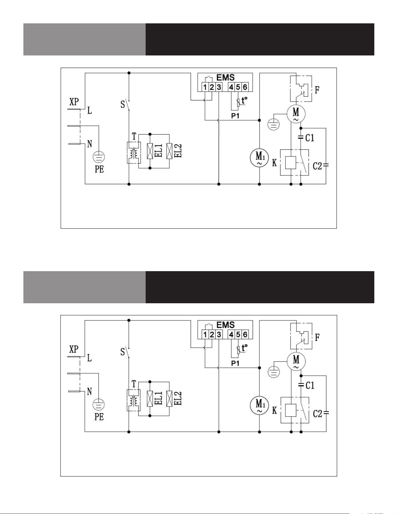
8 OM-HELADERA TIPO MOSTRADOR
Diagrama de cableado
KCICDC4FH
LLAME A LA FÁBRICA SI NECESITA REPUESTOS:
866-339-8515
Diagrama de cableado
KCICDC6FH
LLAME A LA FÁBRICA SI NECESITA REPUESTOS:
866-339-8515
XP-enchufe EMS-controlador P1-sensor de armario M-compresor
F-protector contra sobrecarga M1-ventilador S-interruptor T-transformador
EL1-luz exterior EL2-luz interior K-relé de arranque
C1-condensador de arranque (opcional) C2-condensador de funcionamiento (opcional)
XP-enchufe EMS-controlador P1-sensor de armario M-compresor
F-protector contra sobrecarga M1-ventilador S-interruptor T-transformador
EL1-luz exterior EL2-luz interior K-relé de arranque
C1-condensador de arranque (opcional) C2-condensador de funcionamiento (opcional)
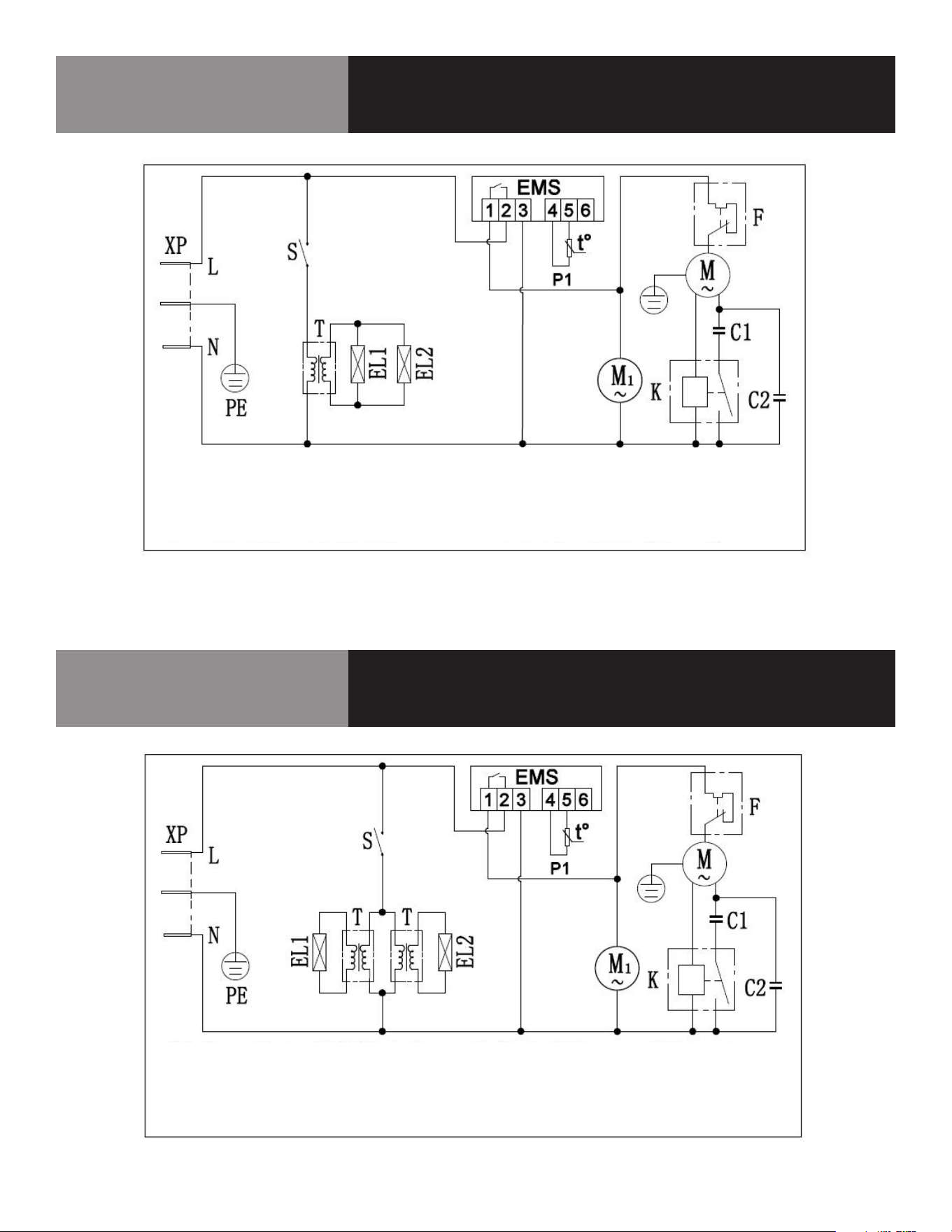
9 OM-HELADERA TIPO MOSTRADOR
Diagrama de cableado
KCICDC8FH
LLAME A LA FÁBRICA SI NECESITA REPUESTOS:
866-339-8515
Diagrama de cableado
KCICDC10FH
LLAME A LA FÁBRICA SI NECESITA REPUESTOS:
866-339-8515
XP-enchufe EMS-controlador P1-sensor de armario M-compresor
F-protector contra sobrecarga M1-ventilador S-interruptor T-transformador
EL1-luz exterior EL2-luz interior K-relé de arranque
C1-condensador de arranque (opcional) C2-condensador de funcionamiento (opcional)
XP-enchufe EMS-controlador P1-sensor de armario M-compresor
F-protector contra sobrecarga M1-ventilador S-interruptor T-transformador
EL1-luz exterior EL2-luz interior K-relé de arranque
C1-condensador de arranque (opcional) C2-condensador de funcionamiento (opcional)

10 OM-HELADERA TIPO MOSTRADOR
Registro de servicio
N.º de modelo: Adquirido a:
Nº de serie: Ubicación:
Fecha de compra: Fecha de instalación:
N.º de orden de compra: Para llamadas al servicio técnico:
Fecha Mantenimiento realizado Realizado por