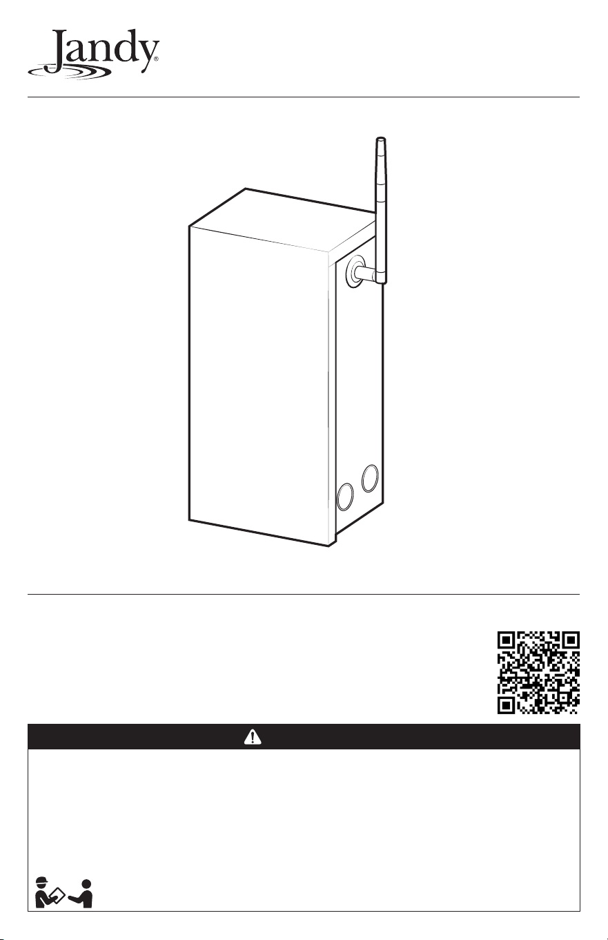
Infinite WaterColors
™
LED Light Controller
This product requires AquaLink
®
RS revision Y or later
or AquaLink EDGE
Essential installation and startup instructions are included in this manual.
Additional operation and troubleshooting information is available online
by scanning the QR code with your phone or visiting jandy.com
WARNING
FOR YOUR SAFETY – This product must be installed and serviced by a contractor who is licensed and qualified in pool
equipment by the jurisdiction in which the product will be installed where such state or local requirements exist.
Themaintainer must be a professional with sufficient experience in pool equipment installation and maintenance so that all
of the instructions in this manual can be followed exactly. Before installing this product, read and follow all warning notices
and instructions that accompany this product. Failure to follow warning notices and instructions may result in property
damage, personal injury, or death. Improper installation and/or operation may void the warranty.
Improper installation and/or operation can create unwanted electrical hazard which may cause serious injury, property
damage, or death.
ATTENTION INSTALLER – This manual contains important information about the installation, operation and
safe use of this product. Thisinformation should be given to the owner/operator of this equipment.
Installation and Operation Manual
Manuel d’installation et d’utilisation
Manual de instalación y operación
Page 2
ENGLISH Jandy
®
Infinite WaterColors
™
LED Light Controller | Installation & Operation Manual
FCC Regulatory Compliance Statement
This device complies with Part 15 of the FCC Rules. Operation is subject to the following two conditions:
1. This device may not cause harmful interference, and
2. This device must accept any interference received, including interference that may cause undesired operation.
CAUTION
Changes or modifications not expressly approved by the party responsible for compliance could void the user’s authority to
operate the equipment.
NOTE: This equipment has been tested and found to comply with the limits for a Class B digital device, pursuant to Part15 of
the FCC Rules. These limits are designed to provide reasonable protection against harmful interference in a residential
installation. This equipment generates, uses and can radiate radio frequency energy and, if not installed and used in
accordance with the instructions, may cause harmful interference to radio communications. However, there is no guarantee
that interference will not occur in a particular installation. Ifthis equipment does cause harmful interference to radio or
television reception which can be determined by turning the equipment off and on, the user is encouraged to try to correct
the interference by one or more of the following measures:
– Reorient or relocate the receiving antenna.
– Increase the separation between the equipment and receiver.
– Connect the equipment into an outlet on a circuit different from that to which the receiver is connected.
– Consult the dealer or an experienced radio/TV technician for help.
Table of Contents
Section 1. Important Safety Instructions .... 3
1.1 Safety Instructions .................................... 3
1.2 Landscape Lighting Instructions .............. 4
1.3 Specifications .......................................... 5
Section 2. Best Installation Practices ......... 5
Section 3. Installation ................................... 8
3.1 Location Requirements for Pool and Spa
Light Applications ..................................... 8
3.2 Mounting ................................................... 8
3.3 High Voltage Wiring .................................. 8
3.4 Low Voltage Wiring
and Communication ................................. 9
3.5 RS-485 Wiring and Communication ......... 9
3.6 Bonding .................................................. 10
Section 4. Connecting to Automation ....... 11
4.1 Connected to AquaLink RS .................... 11
4.2 Connected to AquaLink EDGE ............... 12
Section 5. Additional Online Content ........ 12
Section 6. Troubleshooting ........................ 13
This device must be installed to provide a separation distance of at least 20cm from all persons and must not be collocated
or operating in conjunction with any other antenna or transmitter, except in accordance with FCC multi-transmitter product
guidelines.
ISED Canada Regulatory Compliance Statement
This device contains licence-exempt transmitter(s)/receiver(s) that comply with Innovation, Science and Economic Development
Canada’s licence-exempt RSS(s). Operation is subject to the following two conditions:
1. This device may not cause interference.
2. This device must accept any interference, including interference that may cause undesired operation of the device.
This radio transmitter IC:10837A-WT000354 has been approved by Innovation, Science and Economic Devlopment Canada to
operate with the antenna types listed below, with the maximum permissible gain indicated. Antenna types not included in this list
that have a gain greater than maximum gain indicated for any type listed are strictly prohibited for use with this device.
Antenna Type Input impedance Gain
AANE-WH-0209 Rod Antenna 50Ω
2.
W1038x Rod Antenna 50Ω
4.7
This device complies with ISED radiation exposure limits set forth for an uncontrolled environment. This equipment should be
installed and operated with minimum distance 20cm between the radiator and your body. This transmitter must not be colocated
or operating in conjunction with any other antenna or transmitter.
1 dBi
4
dBi
Jandy
®
Infinite WaterColors
™
LED Light Controller | Installation & Operation Manual ENGLISH
Page 3
Section 1. Important Safety Instructions
IMPORTANT SAFETY INSTRUCTIONS
READ AND FOLLOW ALL INSTRUCTIONS
1.1 Safety Instructions
All electrical work must be performed by a licensed electrician and conform to all national, state, provincial and
local codes. When installing and using this electrical equipment, basic safety precautions should always be
followed, including the following:
WARNING
EQUIPMENT UNDER PRESSURE: Always turn pump off prior to installation or service. Your pump/filter system is
operated under pressure and the pressure must be released before you begin work. Please see your pump/filter owner’s
manual for further instructions.
To reduce the risk of electric shock, fire or injury, service should only be attempted by a qualified pool service
professional.
RISK OF ELECTRIC SHOCK: When installed as a power source for landscape lighting: Install power unit 5 feet (1.5 m)
or more from a pool or spa and 10 feet (3.05 m) or more from a fountain. Where the power unit is installed within 10 feet
(3.05 m) of a pool or spa connect power unit to a GFCI protected branch circuit. Canadian installations must be at least
three (3) meters from the water.
RISK OF ELECTRIC SHOCK WHICH CAN RESULT IN SERIOUS INJURY OR DEATH: Before attempting to install or
service, ensure that all power to the circuit supplying power to the system is disconnected or turned off at the circuit
breaker. All wiring must be done in accordance with the National Electrical Code
®
(NEC)
®
, NFPA-70
®
, including those in
Article 680 - Swimming Pools, Fountains, and Similar Installations.
In Canada, the Canadian Electrical Code (CEC), CSA C22.1, must be followed. All applicable local installation codes and
regulations must be followed.
ATTENTION
This power center and the chlorine generator control center are not to be considered as suitable for use as service
equipment. Therefore, it is required to have the appropriate means of disconnection, circuit isolation, and/or branch circuit
protection installed upstream of the power/control center.
WARNING
To reduce the risk of injury do not permit children to use this product unless they are closely supervised at all times.
Risk of Accidental Drowning. Extreme caution must be exercised to prevent unauthorized access by children. To avoid
accidents, ensure that children cannot use a spa or hot tub unless they are closely supervised at all times
This appliance is not intended for use by persons (including children) with reduced physical, sensory or mental
capabilities, or lack of experience and knowledge, unless they have been given supervision or instruction concerning use
of the appliance by a person responsible for their safety.
PREVENT CHILD DROWNING: Do not let anyone, especially small children, sit, step, lean or climb on any equipment
installed as part of your pool’s operational system. Locate the components of your operational system at least 1 m
3.3 feet (1 m) from the pool so children cannot use the equipment to access the pool and be injured or drown.
To reduce the risk of injury, do not remove the suction fittings of your spa or hot tub. Never operate a spa or hot tub if the
suction fittings are broken or missing. Never replace a suction fitting with one rated less than the flow rate marked on the
equipment assembly.
Page 4
ENGLISH Jandy
®
Infinite WaterColors
™
LED Light Controller | Installation & Operation Manual
A terminal bar marked “GROUND” is provided within the power center. To reduce the risk of electrical shock, connect this
terminal bar to the grounding terminal of your electric service or supply panel with a continuous copper conductor having
green insulation and one that is equivalent in size to the circuit conductors supplying this equipment, but no smaller than
no. 12 AWG (3.3 mm²). In addition, a second wire connector should be bonded with a no. 8 AWG (8.4 mm²) copper wire
to any metal ladders, water pipes, or other metal within five 5 feet (1.5 m) of the pool/spa. In Canada, the bonding wire
must be minimum 6 AWG (13.3 mm²).
Install only on a branch circuit protected by a ground fault circuit interrupter (GFCI), Class A GFCI in Canada. The conductors
on the load side of the ground-fault circuit-interrupter shall not occupy conduit, boxes, or enclosures containing other
conductors unless the additional conductors are also protected by a ground-fault circuit-interrupter. Refer to local codes for
complete details.
CAUTION
This device is intended for use with permanent swimming pools and may also be used with hot tubs and spas if so marked.
Do not use with storable pools. A permanently-installed pool is constructed in or on the ground or in a building such that it
cannot be readily disassembled for storage. A storable pool is constructed so that it is capable of being readily disassembled
for storage and reassembled to its original integrity.
Modifications made to this equipment, which are not authorized by the manufacturer, may void the user’s authority to
operate this equipment.
WARNING
To reduce the risk of FIRE OR INJURY TO PERSONS: Turn off/unplug and allow to cool before replacing lamp.
LAMP GETS HOT QUICKLY! Contact only switch/plug when turning on. Do not touch hot lens, guard, or enclosure (see
diagram/picture). Keep lamp away from materials that may burn. Do not touch the lamp at any time. Use a soft cloth. Oil from
skin may damage lamp. Do not operate the luminaire fitting with a missing or damaged shield. LIGHTED LAMP IS HOT!
SAVE THESE INSTRUCTIONS
1.2 Landscape Lighting Instructions
THIS SECTION INCLUDES INSTRUCTIONS,
PRECAUTIONS AND WARNINGS APPLICABLE TO
LANDSCAPE LIGHTING APPLICATIONS. FOLLOW
ALL REQUIREMENTS OF THIS SECTION WHEN
LIGHT CONTROLLER IS USED IN LANDSCAPE
LIGHTING APPLICATIONS.
CAUTION
For use only on a branch circuit protected by a ground
fault circuit interrupter (GFCI), Class A GFCI in Canada.
WARNING
RISK OF ELECTRICAL SHOCK. Install power unit 5 feet
(1.5 m) or more from a pool or spa and 10 feet (3.05 m)
or more from a fountain. Where the power unit is installed
within 10 feet (3.05 m) of a pool or spa connect power
unit to a GFCI protected branch circuit. In Canada, do not
mount power supply or landscape luminaires within 10
feet (3.05 m) of a swimming pool or spa or fountain.
THIS DEVICE IS ACCEPTED AS A COMPONENT
OFA LANDSCAPE LIGHTING SYSTEM WHERE
THE SUITABILITY OF THE COMBINATION SHALL
BE DETERMINED BY CSA OR LOCAL INSPECTION
AUTHORITIES HAVING JURISDICTION
– IN CANADA, LANDSCAPE LIGHTING POWER
SUPPLIES ARE FOR OUTDOOR USE ONLY.
MOUNT AT LEAST 30 CM ABOVE GROUND.
– THIS DEVICE IS CERTIFIED FOR USE WITH
LANDSCAPE LIGHTING SYSTEMS. THIS
DEVICE IS ACCEPTED AS A COMPONENT OF
ALANDSCAPE LIGHTING SYSTEM WHERE THE
SUITABILITY OF THE COMBINATION SHALL BE
DETERMINED BY CSA OR LOCAL INSPECTION
AUTHORITIES HAVING JURISDICTION.
– DO NOT CONNECT TWO OR MORE POWER
SUPPLIES IN PARALLEL.
– LANDSCAPE LIGHTING SYSTEMS ARE FOR
OUTDOOR USE ONLY. NOT FOR USE IN
DWELLING UNITS.
Jandy
®
Infinite WaterColors
™
LED Light Controller | Installation & Operation Manual ENGLISH
Page 5
1.3 Specifications
Power Supply
Input: 120VAC, 60 Hz, 2.75A
Output: 14 VAC, 60 Hz, max 300W
Enclosure: Type 3RX
Knockouts: 8 total 1/2” - 3/4” combination
AquaLink
®
RS will support control of up to 4
Infinite WaterColors Light Controllers per system.
AquaLink EDGE will support up to 8 controllers
per system. Each controller will support
communication with up to 16 (15W) and 9 (25W)
lights. Ensure the combined light wattage does
NOT exceed 240W per controller.
WARNING
The Infinite WaterColors LED Light Controller should not
be considered suitable for use as service equipment.
Therefore, it is required to have the appropriate means
of disconnection, circuit isolation, and/or branch circuit
protection installed upstream of the power center.
Section 2. Best Installation
Practices
Infinite WaterColors LED Lights use a digital
communication protocol unlike Jandy WaterColors
LED Lights. To ensure proper operation, it is essential
to follow all installation best practices when wiring
and connecting the Infinite WaterColors LED Light
Controller.
Ensure that the pool meets the requirements of the
current National Electrical Code
®
and all local codes
and ordinances. A licensed or certified electrician must
install the electrical system to meet or exceed those
requirements before the underwater light is installed.
Optimal Wiring Architecture
• Keep low voltage wiring as short as possible. Do
not exceed a combined 200’ between the Infinite
WaterColors LED Light Controller and Infinite
WaterColors LED lights.
• Do not run low-voltage and high-voltage in the
same conduit.
• Place the Infinite WaterColors LED Light Controller
as close as possible to the junction box and lights.
• Multiple light controllers require dedicated conduit
runs to each light/junction box; do not share
conduit between different light controllers.
• For all installations, use a minimum of 10 AWG
wire. Refer to Figure 5 for proper wire size on new
or upgraded installations.
NOTE: If necessary, extend the AC line voltage distance between
the Jandy automation system and the Infinite WaterColors
LED Light Controller. Use proper shielded Type TC (or
equivalent) cabling when AC power lines and RS-485 data
cables share the same raceway.
• Junction box wire-to-wire connections should have
maximum wire contact to reduce signal / voltage
loss and ensure reliable performance.
Preferred connection methods:
1. Screw terminals / bus bar
2. Wire nuts
3. Lever / pushin nuts
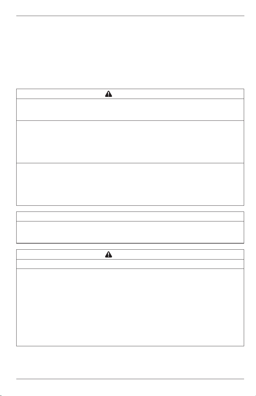
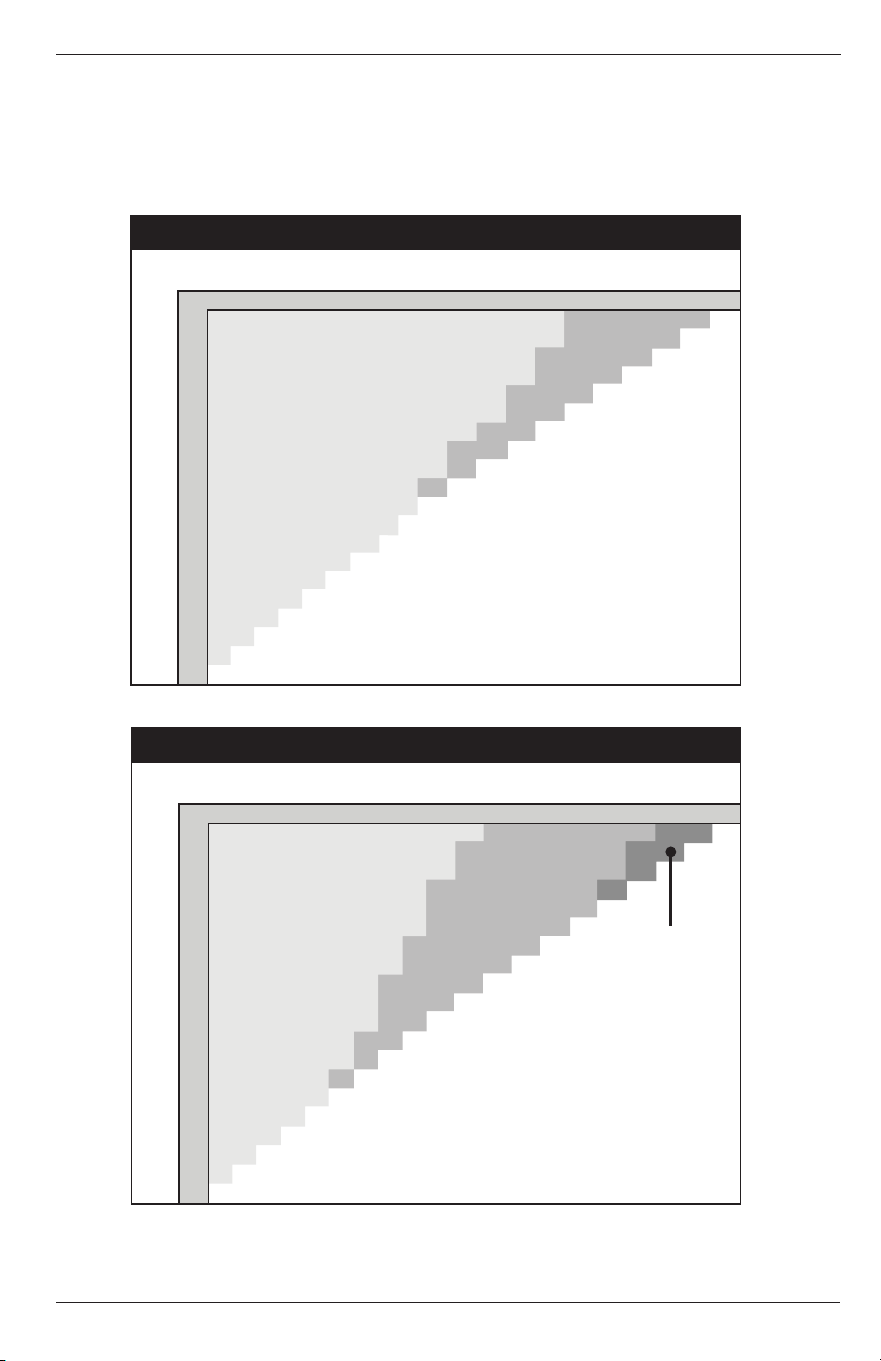
INCORRECT INSTALLATION X
CORRECT INSTALLATION
The light controller, junction box, and lights shall
be installed within 200 ft maximum of each other.
Do not install the light controller, junction box,
and lights more than 200 ft of each other.
*Each controller will support communication with up to
16 (15W) and 9 (25W) lights. Ensure the combined light
wattage does NOT exceed 240W per controller.
*Each controller will support communication with up to
16 (15W) and 9 (25W) lights. Ensure the combined light
wattage does NOT exceed 240W per controller.
Distance DOES NOT exceed 200’
Distance exceeds 200’
Extend AC line voltage if necessary
Shielded "TC" or equivalent cabling must be used if AC
and RS-485 cables share a raceway
Figure 1. Infinite WaterColors Installation
Page 6
ENGLISH Jandy
®
Infinite WaterColors
™
LED Light Controller | Installation & Operation Manual
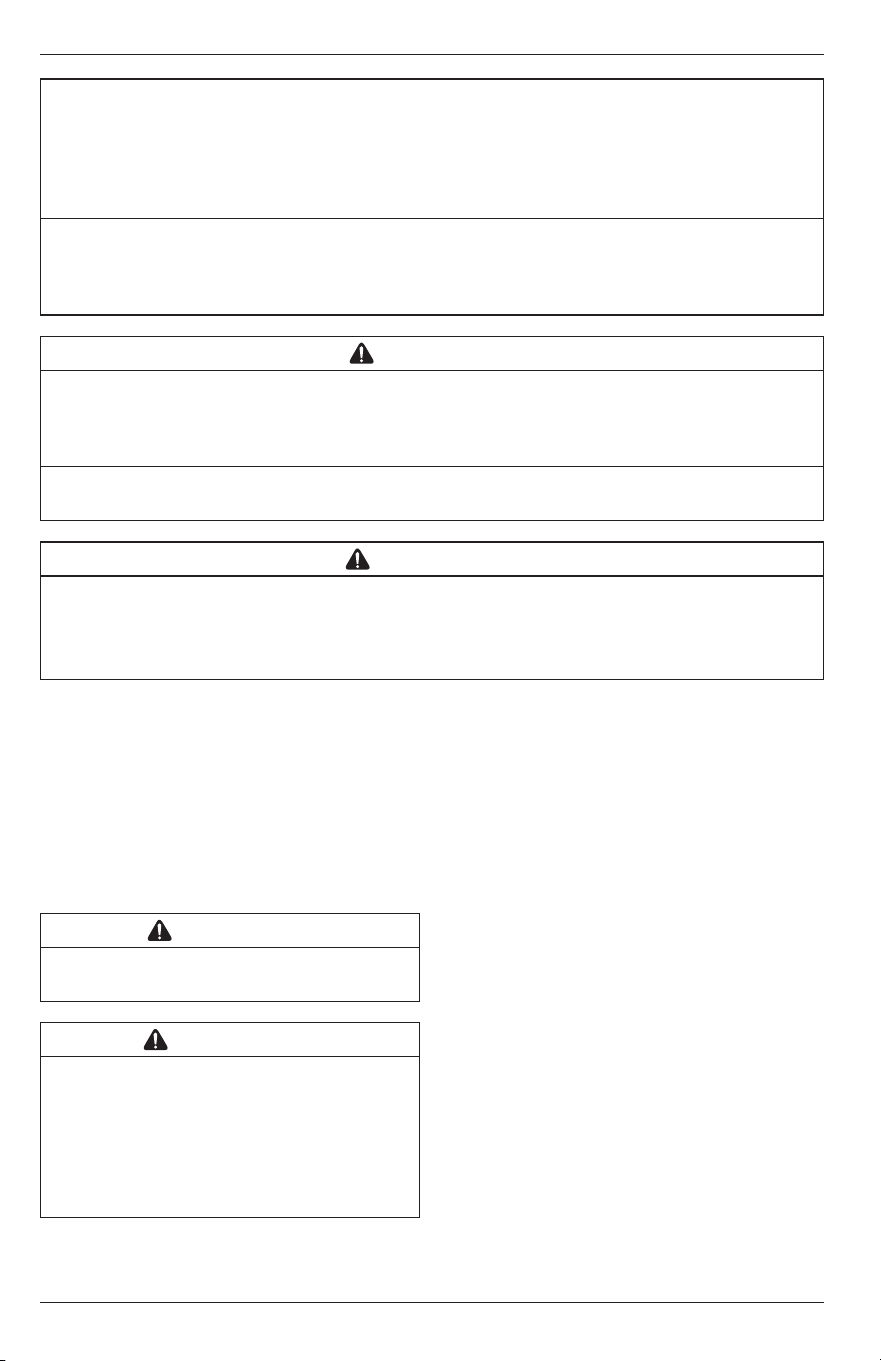
• Aim for star network power distribution where possible. (
See figure 2
)
• Wire lights or junction boxes directly to the power source.
Maximum distance from the light controller to the farthest light is 200 feet
Figure 2. Star Distribution Network
• Junction boxes shall not be daisy chained together. This will create a large load of power at the end of the
power distribution network and will result in communication losses. Wire directly to the power source instead.
(
See Figure 3
)
Figure 3. Do Not Daisy Chain Junction Boxes
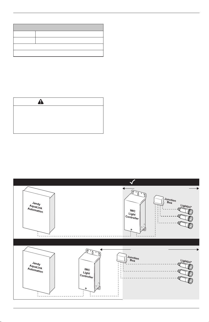
Low Voltage Wire Gauge Selection
• Always use a minimum of 10-gauge (AWG) multi-stranded (braided) wire for the connection between the
Infinite WaterColors LED Light Controller and the junction box.
• Do not wire to a relay. Must be wired directly to a circuit breaker.
Light Controller to Farthest Light
(Not to exceed 200’)
Light Controller to J-Box
Optimal length (0’-10’)
‘A’
J-Box to Farthest Light
‘B’
*Each controller will support communication with
up to 16 (15W) and 9 (25W) lights. Ensure the combined
light wattage does NOT exceed 240W per controller.
Figure 4. Jandy LED Infinite WaterColors Wiring Diagram
Jandy
®
Infinite WaterColors
™
LED Light Controller | Installation & Operation Manual ENGLISH
Page 7
To determine the appropriate wire gauge needed, calculate the total wattage of all lights connected to each
junction box.
• If your total light wattage is less than 120 watts, use 10 gauge (AWG) multi-stranded (braided) wire.
• If the total light wattage is over 120 watts, you must first determine Distance A, then Distance B, before
consulting the charts below.
For total wattage between 120-180W
see figure 5
, for total wattage between 181-240W
see figure 6
.
Total Light Wattage: 181-240
Distance Between Light Controller and J-Box (ft) - B
Distance Between J-Box and Farthest Light (ft) - A
6 AWG
10 AWG
8 AWG
10
20
30
40
50
60
70
80
90
100
110
120
130
140
150
160
170
180
190
200
10 20 30 40 50 60 70 80 90 100 110 120 130 140 150 160 170 180 190 200
Total Light Wattage: 120-180
Distance Between Light Controller and J-Box (ft) - B
Distance Between J-Box and Farthest Light (ft) - A
10 AWG
8 AWG
10
10 20 30 40 50 60 70 80 90 100 110 120 130 140 150 160 170 180 190 200
20
30
40
50
60
70
80
90
100
110
120
130
140
150
160
170
180
190
200
Figure 5. Wire Gauge Selection Chart 120-180W
Total Light Wattage: 181-240
Distance Between Light Controller and J-Box (ft) - B
Distance Between J-Box and Farthest Light (ft) - A
6 AWG
10 AWG
8 AWG
10
20
30
40
50
60
70
80
90
100
110
120
130
140
150
160
170
180
190
200
10 20 30 40 50 60 70 80 90 100 110 120 130 140 150 160 170 180 190 200
Total Light Wattage: 120-180
Distance Between Light Controller and J-Box (ft) - B
Distance Between J-Box and Farthest Light (ft) - A
10 AWG
8 AWG
10
10 20 30 40 50 60 70 80 90 100 110 120 130 140 150 160 170 180 190 200
20
30
40
50
60
70
80
90
100
110
120
130
140
150
160
170
180
190
200
Figure 6. Wire Gauge Selection Chart 120-180W
Page 8
ENGLISH Jandy
®
Infinite WaterColors
™
LED Light Controller | Installation & Operation Manual
Section 3. Installation
3.1 Location Requirements for Pool and
Spa Light Applications
In order to protect the Infinite Water Colors LED Light
Controller from pressurized water spray (such as
that from irrigation sprinklers) and from mechanical
impacts and/or damage, it should be located:
• At least 4 inches (10 cm) above the ground.
• At least 8 inches (20 cm) above the water level.
• At least 4 feet (1.3 m) from the inside edge of
the pool or spa, at least 10 feet (3.05 m) from a
fountain, or as required by local code.
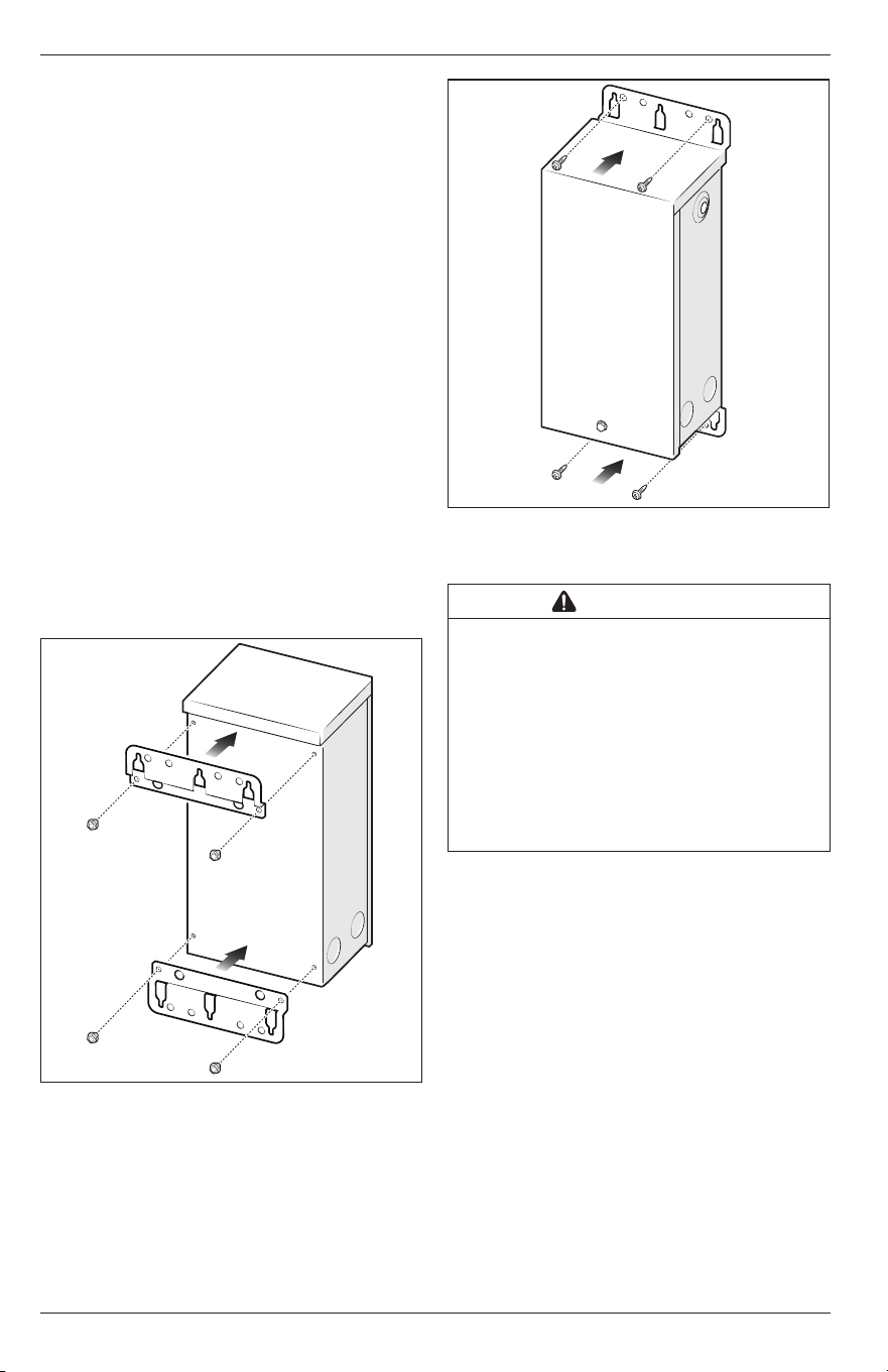
3.2 Mounting
The Infinite WaterColors LED Light Controller is
shipped with mounting brackets fastened on the back.
• Turn the Light Controller over and inspect the
brackets installed inverted on the back.
• If any parts are missing or damaged, please
call your local distributor or technical support at
1.800.822.7933 for assistance.
1. Remove mounting screws from upper and lower
brackets on the back of the Light Controller.
2. Rotate and secure upper and lower brackets with
mounting screws to the same mounting holes, see
Figure 7
.
Figure 7. Install Brackets
3. Mark the location for the mounting screws.
4. Drill holes where the mounting screws will be
installed.
5. Secure screws (or other hardware appropriate for
the mounting surface) through either the keyhole
slots or the mounting holes of the Light Controller
enclosure, see
Figure 8
.
Figure 8. Mounting Light Controller
3.3 High Voltage Wiring
WARNING
RISK OF ELECTRIC SHOCK WHICH CAN RESULT IN
SERIOUS INJURY OR DEATH: Before attempting to
install or service, ensure that all power to the circuit
supplying power to the system is disconnected or turned
off at the circuit breaker. All wiring must be done in
accordance with the National Electrical Code
®
(NEC)
®
,
NFPA70
®
.
In Canada, the Canadian Electrical Code (CEC), CSA
C22.1, must be followed. All applicable local installation
codes and regulations must be followed.
Wiring connections must be made exactly as
showninthe wiring diagram found on the inside of
theInfinite WaterColors LED Light Controller cover.
The NEC and CEC also require that pool equipment
be bonded together as part of the equipotential
bonding grid. Fluidra provides a labeled bonding lug
on the bottom of the Light Controller to accommodate
this requirement.
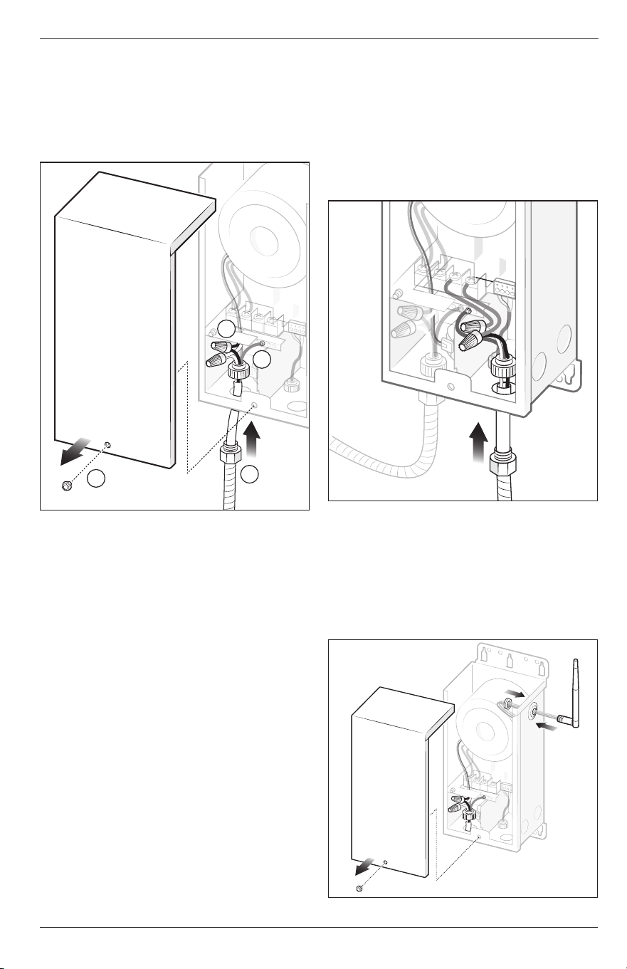
1. Turn off power at the breaker panel.
2. Remove the cover. The cover is held on by one
screw, see
Figure 9
(a).
3. Remove a knockout from the bottom left side of
theLight Controller.
4. Thread a conduit connector that is rated to local
code into the knockout hole on the Light Controller,
see
Figure 9
(b).
5. Feed 120 VAC through the conduit and conduit
connector on the Light Controller, see
Figure 9
.
NOTE: Power the Infinite WaterColors LED Light Controller directly
from a breaker, do NOT wire to a relay.
Jandy
®
Infinite WaterColors
™
LED Light Controller | Installation & Operation Manual ENGLISH
Page 9
6. Connect the green ground wire to the ground
terminal bar in the Light Controller, see
Figure 9
(c).
7. Use wire nuts to connect the line wires (black to
black) and neutral wires (white to white), see
Figure 9
(d).
8. Proceed to
Section 2.4, Low Voltage Wiring and
Communication
.
d
c
b
a
Figure 9. Connect High Voltage Wires
3.4 Low Voltage Wiring and
Communication
1. Remove a knockout from the bottom right side of
the Light Controller.
2. Thread a conduit connector into the knockout hole
on the Light Controller, see
Figure 10
.
NOTE: Provide a dedicated conduit for each light controller. For
systems with more than one controller, ensure that the
wiring for each controller is routed through its own separate
conduit.
3. Feed low voltage light cord through the conduit
and conduit connector on the Light Controller, see
Figure 10
.
NOTE: It is recommended to add a junction box when installing
more than two lights. Low voltage wires are not polarity
sensitive.
4. Use wire nuts to connect the low voltage light
wires, white wire connects to orange wire and
black wire connects to orange wire, see
Figure
9
. Ifinstalling a niched light, connect the green
ground wire to the terminal bar in the controller.
5. Install cover and secure hand tight with the screw
provided.
6. Turn on the breaker to restore power.
NOTE: For AquaLink RS systems with multiple Jandy Infinite
WaterColors LED Light Controllers, ensure only one
controller is powered at a time when assigning lights to
minimize risk of crosstalk between units.
7. Once power is restored, verify pool lights perform
the “rainbow sequence” (it could take up to two
minutes), this indicates the lights are powered and
communicating to the Light Controller.
NOTE: A blinking yellow pool light means no communication
between lights and the light controller.
Figure 10. Connect Low Voltage Wires
3.5 RS-485 Wiring and Communication
1. Turn off power at the breaker panel.
2. Screw the antenna onto the connector hand tight.
NOTE: When connecting the device the antenna may be
repositioned or relocated (using R1106900 - AquaLink
EDGE Antenna Mount with Extension) for improved
connection as needed.
Figure 11. Antenna Install
Page 10
ENGLISH Jandy
®
Infinite WaterColors
™
LED Light Controller | Installation & Operation Manual
See instructions to connect via Wi-Fi in your AquaLink
EDGE manual.
The antenna LED light ring shows the status of the
light controller when connected to an AquaLink EDGE
system. See Figure 12 for descriptions of the status
indicators.
LED Light Ring Indicators
When connected to RS, light ring will remain off
SOLID
Green Connected, verified
Blue BLE pairing
Yellow Service mode
Red Cannot connect, already verified
SLOW FLASH
Green Connected, not verified
Red Not connected, not verified
Yellow OTA in progress
FAST FLASH
Blue Find me enabled
Figure 12. LED Light Ring Indicators
3. Remove the cover. The cover is held on by one
screw, see Figure 9 (a)
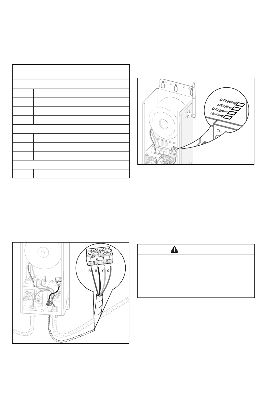
4. RS-485 comes factory wired to the Light Controller.
Connect the low voltage RS-485 communication
low voltage wires to either the AquaLink RS or
AquaLink EDGE automation system. First wire red
(R) to 1, black (B) to 2, yellow (Y) to 3, and green (G)
to 4 on the connector, see Figure 13.
R
B
Y
G
1
2
3
4
Figure 13. Connect RS-485 Wires
5. Check all connection points and wiring for secure
connections.
NOTE: Cover screw ensures bonding to ground, and must be
secured in place.
6. Turn on the breaker to restore power.
Confirm the LED status indicators listed below:
- LED1: Turns on red when powered
- LED2: Continuously flashes green when
communicating to automation
- LED3: Turns on yellow if communicating with
AquaLink EDGE
- LED4: Flashes blue if a communication error
with lights is detected
Pool & Spa Lights will be off due
to control from automation, see Figure 14.
Figure 14. LED Lights
7. Install cover and secure hand tight with the screw
provided.
3.6 Bonding
Fluidra requires that the Infinite Water Colors LED
Light Controller be connected to a “bonding loop”
that includes all electrical equipment in the system
and on the equipment pad. Bonding lugs must be
connected with a solid copper wire not smaller than
8 AWG (6AWG in Canada). Failure to do so may void
the Fluidra warranty.
CAUTION
To prevent premature failure of the equipment resulting
from stray voltages and voltage differentials, the Infinite
WaterColors LED Light Controller must be bonded to
other equipment which is part of the pool plumbing
system with a solid copper wire not smaller in diameter
than 8 AWG (6 AWG in Canada).
Additionally, in the United States the National
Electrical Code
®
(NEC
®
) and in Canada the Canadian
Electrical Code (CEC), require that all metallic
components of a pool structure, including reinforcing
steel, metal fittings and above ground components be
bonded together (forming an equipotential bonding
grid) with a solid copper conductor not smaller than
an8 AWG (6 AWG in Canada).
The NEC and CEC also require that the equipment
and/or appliances associated with the pool water
circulating system, including, but not limited to, pump
motors and heaters, be bonded together as part of the
equipotential bonding grid. Fluidra provides special
labeled bonding lugs on the bottom of the power
center to accommodate this requirement.
Jandy
®
Infinite WaterColors
™
LED Light Controller | Installation & Operation Manual ENGLISH
Page 11
After bonding the electronics to the grounding lug,
installer must verify ground continuity of all metal
components using a multimeter.
WARNING
Installer must ensure that the Infinite WaterColors LED
Light Controller is in acceptable working condition;
including all seals/gaskets must be in place and
functional; grounding lug must be present, functional,
and bonded; and corrosion must not compromise ingress
protection against weather. Additionally, all hardware must
be present and functional. If any of the aforementioned
conditions are not met, a new enclosure MUST be used.
WARNING
Risk of electric shock which can result in serious
injury or loss of life. Before attempting to install
or service, ensure that all power to the circuit
supplying power to the system is disconnected or
turned off at the circuit breaker. All wiring must
be done in accordance with the National Electrical
Code
®
(NEC)
®
, NFPA-70
®
.
In Canada, the Canadian Electrical Code (CEC), CSA
C22.1, must be followed. All applicable local installation
codes and regulations must be followed.
Wiring connections must be made exactly as shown
in the wiring diagram found on the inside of the Infinite
WaterColors LED Light Controller cover. TheNEC
and CEC also require that pool equipment be bonded
together as part of the equipotential bonding grid.
Fluidra provides a labeled bonding lug on the bottom of
the Light Controller to accommodate this requirement.
Section 4. Connecting to Automation
This product requires connection to either Jandy
AquaLink RS (Rev Y or greater), or AquaLink EDGE.
The programming is different based on which
automation system is being used.
Download the iAquaLink app or upgrade to the latest
version prior to light and zone set up. App function
and design is subject to change.
NOTE: When replacing lights, make sure to follow these steps:
• Remove any existing light aux names (system
setup > label aux >)
• Remove previous light aux labels (system setup >
color lights)
• Remove schedules of light auxiliaries (system setup
> schedules)
4.1 Connected to AquaLink RS
4.1.1 Light Setup
NOTE: For AquaLink RS systems with multiple Jandy Infinite
WaterColors LED Light Controllers, ensure only one
controller is powered at a time when assigning lights to
minimize risk of crosstalk between units.
1. Open the app on your device.
2. From My Systems page, select your pool.
3. From the home page, choose the cog system icon
on the top right and select System Setup.
• Assign Lights
1. From the System Setup page, select Light Setup
and Assign Lights.
2. From the Assign Lights pop up, choose proceed
tocontinue the process.
3. On the Light Zone Setup page, select a light in
order to move it to a different zone. Selected
light will flash the color of the zone it’s currently
assigned to. Follow further instructions in the app.
NOTE: Default zone colors include: zone 1 (green), zone 2 (white),
zone 3 (red), and zone 4 (blue).
When exiting the Light Zone Setup page, the lights will turn
off.
Lights have to be assigned to a zone in order to rename the
zone.
• Name Light Zones
1. Go to > System Setup > Light Setup > Zone Name.
2. From the Edit Zone Name pop up, enter the zone
name and choose OK.
4.1.2 Turn Lights On/Off
1. Open the app on your device.
2. From My Systems page, select your pool.
3. Choose the equipment page.
4. Turn zone lights on/off by tapping the toggle to the
right of the desired zone.
NOTE: Ability to turn light zones on/off is only done through
theapp.
4.1.3 Select Colors
1. Open the app on your device.
2. From the My System page, select your pool.
• Select Custom Color
1. Go to > equipment page.
2. From the equipment page, choose the zone you
want to change color.
3. From that zones page, choose Custom Color.
4. Choose your custom color from the color wheel.
5. Choose Apply to apply the custom color to your
zone.
• Preset Colors
1. Go to the equipment page and select the zone you
want to change color.
2. After selecting the zone, then choose from the list
of preset colors to apply that preset color to your
zone.
• Preset Color Shows
1. From equipment page, choose the zone you want
to change color.
2. After selecting the zone, then choose from the list
of preset color shows to apply that preset color
show to your zone.

Page 12
ENGLISH Jandy
®
Infinite WaterColors
™
LED Light Controller | Installation & Operation Manual
4.1.4 Adjust Brightness
1. From the equipment page, select the sun icon on
the zone where you want to adjust the brightness.
2. Move the slider bar up or down with your finger
andthen click apply to change the brightness.
4.2 Connected to AquaLink EDGE
4.2.1 Light Setup
Navigate to the light assignment center on the EDGE
display. Follow the on-screen instruction to set up
your lights. Light controls are grouped inside spaces.
4.2.2 Turn Lights On/Off
To turn lights on enter the space and select the light
group. Follow the on-screen instructions to achieve
the desired effect.
4.2.3 Select Colors
To select colors enter the space and select the light
group. Follow the on-screen instructions to achieve
the desired effect.
Section 5. Additional Online Content
For information on the following, please refer to the
online manual:
– System Overview
– OneTouch Setup (AquaLink RS only)
– Amazon Alexa Light Control (AquaLink RS only)
– Online content for EDGE
– Troubleshooting

Jandy
®
Infinite WaterColors
™
LED Light Controller | Installation & Operation Manual ENGLISH
Page 13
Section 6. Troubleshooting
PROBLEM POSSIBLE CAUSE CORRECTION ACTION
Lights don’t turn on Light zone is not enabled Ensure that the light is in an enabled zone.
No power / controller failure (red LED off) Verify the following:
- The breaker has not tripped.
- 120 VAC is present on the input pigtail, check wiring if not
present.
- 14VAC is present on screw terminals.
- The light controller's red LED is on. If NO, verify the
automation fuse has not blown.
- If the automative fuse has not blown, replace controller PCBA.
Light wiring Verify the junction box closest to the light is reading 14 VAC.
Rewire the connections to ensure good electrical contact.
Ensure that appropriately sized stranded wire is being used.
Refer to Low Voltage Wire Gauge Selection on page 6-7.
Light failure Disconnect RS485 from the light controller and power cycle the
unit. Check whether the light performs the "rainbow" sequence.
For niched lights, remove the light from the pool and open to
check for 14VAC on the terminals inside. If 0V, replace the full
unit (broken cable), otherwise replace the PCBAs only.
Lights are out of sync Zones are set differently Verify that lights are in the same zone, or the same light show
is applied to all zones
One or more lights are
dim, blinking or not
working
Poor connection Verify wiring and connections
Voltage sag Verify that the correct wire gauge is being used and is stranded.
Refer to Low Voltage Wire Gauge Selection on page 6-7.
Cross talk between multiple light
controllers
To ensure that there are no learn in issues or duplicate lights
as a result of cross talk between multiple light controllers at
startup, or when replacing one or more lights, follow the steps
below to reset the units and learn the lights in correctly:
- Ensure light controllers are routed in separate, dedicated
conduits or run with shielded cable. Shared conduit with
multiple light controllers will result in crosstalk issues.
- Disconnect RS485 from all light controllers.
- Factory reset all light controllers by holding the factory reset
button on the control board for 7 seconds while powered.
- Power off all light controllers.
- Clear memory on the RS, or forget the device in EDGE.
- Plug in RS485 to all light controllers.
- Power on 1 light controller at a time to learn the controller
and lights into automation.
- Once all light controllers have been learned in, set up zones
and assign lights.
- Verify the issues are resolved.
Lights are flashing
yellow
Third party transformer Only the Jandy LED Light Controller can be used to power and
communicate with Infinite WaterColors lights. Replace any thrid
party transformers with IWCLC300W2.
Controller communication Check the DCT red LED status.
If the unit is OFF, verify that 14 VAC is present at the screw
terminals. If 14 VAC is confirmed, replace the DCT.
If ON, verify that the wiring is properly sized, stranded, and that
secure connections are present at each junction box. Refer to
Best Installation Practices on pages 5-7

Page 14
ENGLISH Jandy
®
Infinite WaterColors
™
LED Light Controller | Installation & Operation Manual
Different colors from
other lights
Lights in different zones Verify that lights are in the same zone, or that all zones are set
to the same color. If colors still wont match, refer to light failure
corrective actions.
Light failure Turn all lights to Ruby Red, then Emerald Green, then Cobalt
Blue. If any of the colors did NOT work, check the light for
physical damage or water intrusion.
Zones / lights not
showing up in the app
No lights connected Verify at least 1 light is conencted. Light setup and zones
will only appear once at least 1 light is connected and
communicating.
RS485 wiring / communication Check if light controller green LED is flashing. If yes, confirm
the controller appears in the automation device list and
continue with the following steps.
- Verify that wiring is correct (1 - red, 2 - black, 3 - yellow,
4 - green). Incorrect wiring at other devices can also affect the
light controller.
- Check for 10 VDC at the light controller red 4-pin connector. If
no voltage is present, proceed to the next step.
- Check continuity on black and yellow comm wires between
automation and the light controller to ensure they are not
damaged or broken.
Automation failure Confirm if other RS485 devices operating properly. If not, verify
for the following:
- Check for 10 VDC at the RS system. If 10 VDC is missing,
replace the RS.
- Check for continuity between automation and light controller
red 4 pins to ensure no RS485 wires are broken.
Light controller failure Unplug the RS485 and power cycle the light controller. Verify
the lights perform the "rainbow" sequence on power up.
-If yes, the device is good, check comms further.
-If no, connect a known good light directly to the light controller
to identify whether the issue is the controller or light. Replace
as needed.